standardsbased cylinder dnci
TRANSCRIPT

en Operating
instructions
8072823
2017-05e
[8072825]
standardsbased cylinder
DNCI
DNCI
2 Festo – DNCI – 2017-05e
Original instructions
Identification of hazards and instructions on how to prevent them:
Danger
Immediate dangers which can lead to death or serious injuries
Warning
Hazards that can cause death or serious injuries
Caution
Hazards that can cause minor injuries
Other symbols:
Note
Material damage or loss of function
Recommendations, tips, references to other documentation
Essential or useful accessories
Information on environmentally sound usage
Text designations:
� Activities that may be carried out in any order
1. Activities that should be carried out in the order stated
– General lists
� Result of an action/References to more detailed information

DNCI
Festo – DNCI – 2017-05e English 3
Standard cylinder DNCI
For all available product documentation � www.festo.com/pk
1 Operating parts and connections
1
2
3
456
7
8
9
1 Compressed air connections
2 Grooves for proximity switch
3 Electrical connection of the measuringhead
4 Measuring head
5 Flange screws with threaded holes forfastening
6 Piston rod with integrated magneticmeasuring tape
7 Pivot for counter holding the piston rod
8 Centering collar
9 Earth/ground connection
Bild 1

DNCI
4 Festo – DNCI – 2017-05e English
2 Method of operation and application
When the compressed air connections are pressurized alternately, the piston rod ofthe piston rod drive with integrated incremental measuring system DNCI moves inand out.There is a magnetic tape in the piston rod. A sensor in the bearing cover convertsthe magnetic pulses of the magnetic tape into electric signals depending on thepositioning path of the standard cylinder.
The DNCI has been designed for transporting work masses. The integrated measuring system has been designed for monitoring the pistonposition in combination with a positioning controller from Festo (e.g. CMPX, CMAX,SPC200, SPC11 ”Soft Stop”) or for use as a measuring cylinder.
The DNCI is not intended for use in manufacturing processes which are sensitive tocopper or PTFE.
3 Transport and storage
� Take into account the weight of the DNCI.
Depending on the design the DNCI can weigh over 10 kg.
� Ensure storage conditions as follows:
– short storage periods,– cool, dry, shaded storage locations protected from corrosion,– no influence from magnetic fields.
4 Conditions of use
Please noteSpecial conditions apply to the electronic control of the DNCI:
� Take into account the warnings and instructions in the descriptions of thepositioning controller.
Please noteMalfunctioning will occur if the device is not used correctly.
� Make sure that the specifications in this chapter are always observed.
Only in this way can you ensure correct and reliable functioning.
DNCI
Festo – DNCI – 2017-05e English 5
� Compare the maximum values specified in these operating instructions withyour actual application (e.g. pressures, forces, torques, temperatures, masses,speeds, voltages).
Only if the loading limits are observed can the DNCI be operated in accordancewith the relevant safety guidelines.
� Observe the specifications applicable to your location, as well as all local andnational laws and regulations.
� Remove all transport packaging such as foils, caps and cartons (except for anyplugs in the pneumatic connections).
The packing is intended for recycling (except for oiled paper which must bedisposed of ).
� Observe the ambient conditions at your location.
� Make sure that the compressed air is correctly prepared (here: filtered, driedand non-lubricated / see ’Technical specifications’).
� Once a medium has been selected, keep this unchanged over the completeservice life of the product (media quality see ’Technical specifications’).
� Pressurize your complete system slowly until the operating pressure is reached.
All movements of the actuators will then be controlled.For slow start-up pressurization use safety start-up valve HEL or HEM.
� Use the DNCI in its original state without undertaking any modifications.

DNCI
6 Festo – DNCI – 2017-05e English
5 Fitting
Fitting mechanical components
� Check the use of the DNCI
– as a measuring cylinder– with electronic control.
Please noteUsing the DNCI with electronic control:
� Use the DNCI only in the permitted mounting positions (see here the drive-specific information on the positioning controllers).
� When fitting the mechanical parts, take into account the instructions in themanuals for the positioning controller.
� Make sure that tubing and connection accessories have sufficient space formovement.
If the cylinders are arranged parallel:
� Take the following minimum space requirements into account: Otherwise themagnetic fields of the two cylinders will influence each other and lead to evaluation faults in the measuring system.
Parallel arrangement
Bearing cover flush Bearing cover offset (Y › 0)
No minimum distance Minimum distance X > 70 mm

DNCI
Festo – DNCI – 2017-05e English 7
With direct fastening or if mounting accessories are used, in each case withcylinder collar milling:
� Select one of the fastening possibilities listed in the following table:
Double screwing with foot fasteningHNA in the threaded holes of thecover screws
Double screwing with foot fasteningFNC in the threaded holes of thecover screws
Bild 2
The different product sizes have connector threads of the following design andwith the following tightening torques:
DNCI-... 32 40 50 63
Connector thread M6 M6 M8 M8
Tightening torque [Nm] 5 5 8 8
Bild 3
� Tighten the fastening screws equally.

DNCI
8 Festo – DNCI – 2017-05e English
If accessories are mounted on the piston rod:
� Use the following elements:
– only the thread of the piston rod.– the pivot 7 on the piston rod for
counterholding (only in the retractedend position). The maximum torque onthe bearing must not exceed 5 Nm.
– an external guide for the work load. This will prevent lateral loadings on thepiston rod. Lateral loadings produce false measuring results and may damage themeasuring system.
If additional proximity switches are used:
� Place the proximity switches in the fastening grooves.
Cover rails over the grooves fasten thecables and protect them against dirt.
� Use cover rails in all unused grooves inaccordance with the chapter ’Accessories’(protection against dirt).
Fitting pneumatic components
� Remove the sealing elements from thecompressed air connections.
� Connect the tubing of the DNCI to thecompressed air connections.
DNCI-... 32 40 50 63
Connectorthread
G1/8 G1/4 G1/4 G3/8
Bild 8
Bild 4
Bild 5
Bild 6
Bild 7

DNCI
Festo – DNCI – 2017-05e English 9
If the DNCI is used as a measuring cylinder:
� Screw the one-way flow control valves of GRLZ or GRLA directly into the relevant compressed air connections.
One-way flow control valves enable the speed to be set.
If the DNCI is used with electronic control:
Please note� Take into account the special fitting re
gulations and instructions for the DNCIin the manuals for the positioning controller.
� Use the proportional directional controlvalve MPYE for controlling the DNCI�.
The proportional directional control valvein conjunction with the controller electronics creates the desired movement bymeans of the difference in pressure on thetwo piston surfaces.
Fitting electric components
� Avoid external influences by magnetic orferritic parts in the vicinity of the measuring head (approx. 100 mm).
This will guarantee that the sensor functions faultlessly.
� Insert the screw with cutting thread supplied into the hole for the earth connection 9.
This will ensure the electrical contact inspite of the anodizing layer.
� Connect the earth cable with low impedance (short cable with large cross-sectional area) to the earth potential.
Bild 9
Bild 10

DNCI
10 Festo – DNCI – 2017-05e English
If the DNCI is used with electronic control:
� Connect the measuring system connection with the cable in accordance withthe manuals for the positioning controller.
If the DNCI is used as a measuring cylinder:
� Connect the measuring system as follows:
Pin Cable colour Designation Pin assignment (view of plug)
1 black +Ub
2 brown 0 V
3 red Signal sine +
4 orange Signal sine -
5 green Signal cosine -
6 yellow Signal cosine +
7 Screening/shield Screening/earth
8 – n.c.
Bild 11
6 Commissioning
WarningUncontrolled moving parts can cause injuryto people in the vicinity of the DNCI.
� Make sure that nobody can place his/herhand in the positioning range of thework load (e.g. by means of a protectivescreen). If the DNCI is protected correctly, it should not be possible to gainaccess to it until it has come to a complete stand.
� Make sure that no objects project intothe positioning range of the work load.
Bild 12

DNCI
Festo – DNCI – 2017-05e English 11
If the DNCI is used as a measuring cylinder:
� Observe the commissioning instructions for the measuring signal amplifierused.
1. Push the piston rod at first into a mechanical end position.
2. Screw the one-way flow control valves into both compressed air connections
– at first completely (as supplied from the factory),– then open them up again one turn.The DNCI will then move slowly over the complete positioning path.
3. Slowly pressurize the compressed air connection of the mechanical endposition.
4. Start a test run.
5. Unscrew the one-way flow control valves until the desired speed is reached.
6. Conclude the test run.
If the DNCI is used with electronic control:
Please noteSpecial commissioning regulations apply to the electronic control of the DNCI:
� Observe the instructions in the manuals for the positioning controller whencommissioning.
� Start a test run (at the lowest permitted pressure).
� Check to see if the settings on the DNCI or on the controller need to be modified:
– Reference stop– Speed– Switching points– Movement sequence
� Conclude the test run.

DNCI
12 Festo – DNCI – 2017-05e English
7 Operation
WarningUncontrolled moving parts can causeinjury to people in the vicinity of theDNCI�.
� Make sure that nobody can place his/her hand in the positioning range of thework load (e.g. by means of a protectivescreen). If the DNCI is protected correctly, itshould not be possible to gain access toit until it has come to a complete stand.
� Make sure that no objects project intothe positioning range of the work load.
8 Care and maintenance
� Do not adjust screws or threaded pins for which there is no direct request formodification in these operating instructions.
In this way you will prevent damage to the cylinder at a later stage.
Cleaning
� Clean the exterior of the DNCI with a soft cloth.
The following cleaning agents are permitted:
– soap suds (max. + 60 °C)– petroleum ether– all non-abrasive cleaning agents.
Bild 13
DNCI
Festo – DNCI – 2017-05e English 13
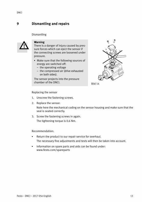
9 Dismantling and repairs
Dismantling
WarningThere is a danger of injury caused by pressure forces which can eject the sensor ifthe connecting screws are loosened underpressure.
� Make sure that the following sources ofenergy are switched off:– the operating voltage – the compressed air (drive exhausted
on both sides).
The sensor projects into the pressurechamber of the DNCI.
Replacing the sensor
1. Unscrew the fastening screws.
2. Replace the sensor.
Note here the mechanical coding on the sensor housing and make sure that theseal is seated correctly.
3. Screw the fastening screws in again.
The tightening torque is 0.6 Nm.
Recommendation:
� Return the product to our repair service for overhaul.
The necessary fine adjustments and tests will then be taken into account.
� Information on spare parts and aids can be found under: www.festo.com/spareparts
Bild 14
DNCI
14 Festo – DNCI – 2017-05e English
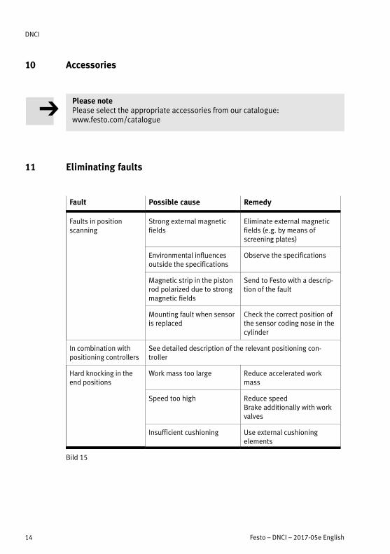
10 Accessories
Please notePlease select the appropriate accessories from our catalogue: www.festo.com/catalogue
11 Eliminating faults
Fault Possible cause Remedy
Faults in positionscanning
Strong external magneticfields
Eliminate external magneticfields (e.g. by means ofscreening plates)
Environmental influencesoutside the specifications
Observe the specifications
Magnetic strip in the pistonrod polarized due to strongmagnetic fields
Send to Festo with a description of the fault
Mounting fault when sensoris replaced
Check the correct position ofthe sensor coding nose in thecylinder
In combination withpositioning controllers
See detailed description of the relevant positioning controller
Hard knocking in theend positions
Work mass too large Reduce accelerated workmass
Speed too high Reduce speedBrake additionally with workvalves
Insufficient cushioning Use external cushioningelements
Bild 15

DNCI
Festo – DNCI – 2017-05e English 15
12 Technical specifications
DNCI-... 32 40 50 63
Design Double-acting pneumatic cylinder with integrated,incremental measuring system
Mounting position As desired (as measuring cylinder and for positioning)Vertical (with Soft Stop)
Operating medium Compressed air to ISO 8573-1:2010 [6:4:4]
Operating pressure range 1 ... max. 12 bar (as measuring cylinder), in conjunction with positioning controllers see relevant manual
Connector thread G1/8 G1/4 G1/4 G3/8
Temperature range - 20 ... + 80 °C (ambient/storage)
Theoretical work force at 6�bar
– running forwards 483 N 754 N 1178 N 1870 N
– running backwards 415 N 633 N 990 N 1682 N
Max. permitted torsionalmoment on piston rod
5 Nm
Positioning speeds asmeasuring cylinder1)
– minimum 0.05 m/s
– maximum 1.5 m/s
Stroke reserve2) 10 mm 15 mm
Repetition accuracy as a measuring cylinder
0.1 mm, in conjunction with positioning controllerssee relevant manual
Accuracy of measurement ± (0,07 mm ± 0,02*L/m)3)
1) In conjunction with positioning controllers higher speeds can be achieved
(see manuals for the positioning controllers).
2) Work stroke = stroke - 2 x stroke reserve
3) L = Length of measuring system in meters

DNCI
16 Festo – DNCI – 2017-05e English
DNCI-... 32 40 50 63
Displacement resolution
– With CASM or DADE 0,005 mm
– With SPC11 or SPC200 0,02 mm
Electrical connection Cable with plug, round form, M12, 8-pin
CE marking (see declaration ofconformity)4)
� www.festo.com/sp
In accordance with EU EMC Directive
Cable length 1500 mm (max. 30 m)
Interface Analogue
Resistance to vibration as perIEC 68 part 2-6
0.35 mm path at 10 ... 60 Hz; 5 g acceleration at 60 ... 150 Hz
Resistance to shock as perIEC�68 part 2-27
± 30 g at 11 ms duration;5 shocks in each direction
Materials Housing: Aluminium, anodized
Piston rod, collar screws: Steel
Bearings: POM
Piston guide: PBT, POM
Seals: PU, NBR
Sensor housing: POM
Plug housing: PBT
Cable coating: PUR
Approx. weight [kg]
0-stroke (DNCI-...-S2) 0.52 (0.59 ) 0.85 (0,98) 1.32 (1.55) 1.91 (2.17)
per 10 mm stroke (DNCI-...-S2) 0.03 (0.04) 0.04 (0,06) 0.06 (0.09) 0.07 (0.1)
4) The device is intended for use in an industrial environment. Outside of industrial environments, e.g. in commer
cial and mixed-residential areas, actions to suppress interference may have to be taken.
Bild 16

DNCI
Festo – DNCI – 2017-05e English 17

Reproduction, distribution or sale of this document or communication of its contents to others without express authorization isprohibited. Offenders will be liable for damages. All rights reserved in the event that a patent, utility model or design patent isregistered.
Copyright:Festo SE & Co. KGRuiter Straße 8273734 EsslingenGermany
Phone:+49 711 347-0
Fax:+49 711 347-2144
E-mail:[email protected]
Internet:www.festo.com