standards-based cylinders dnci, with measured-value
TRANSCRIPT
Standards-based cylinders DNCI, with measured-value transducer DADE
TOC BookmarkStandards-based cylinders DNCI, with measured-value transducer DADEKey features
Type codes
Peripherals overview
Data sheet
Technical data
Materials
Dimensions
Ordering data – Modular product system
Accessories
Measured-value transducer
2 d Internet: www.festo.com/catalogue/... Subject to change – 2021/09
Standards-based cylinders DNCI, with measured-value transducer DADE
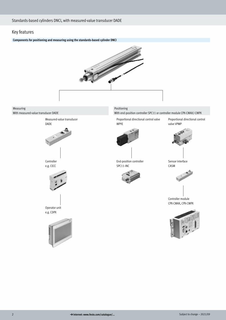
Key features
Components for positioning and measuring using the standards-based cylinder DNCI
MeasuringWith measured-value transducer DADE
PositioningWith end-position controller SPC11 or controller module CPX-CMAX/-CMPX
Measured-value transducerDADE
Controllere.g. CECC
Operator unite.g. CDPX
Proportional directional control valveMPYE
End-position controllerSPC11-INC
Proportional directional control valve VPWP
Sensor interfaceCASM
Controller moduleCPX-CMAX, CPX-CMPX
Key features
32021/09 – Subject to change d Internet: www.festo.com/catalogue/...
Standards-based cylinders DNCI, with measured-value transducer DADE
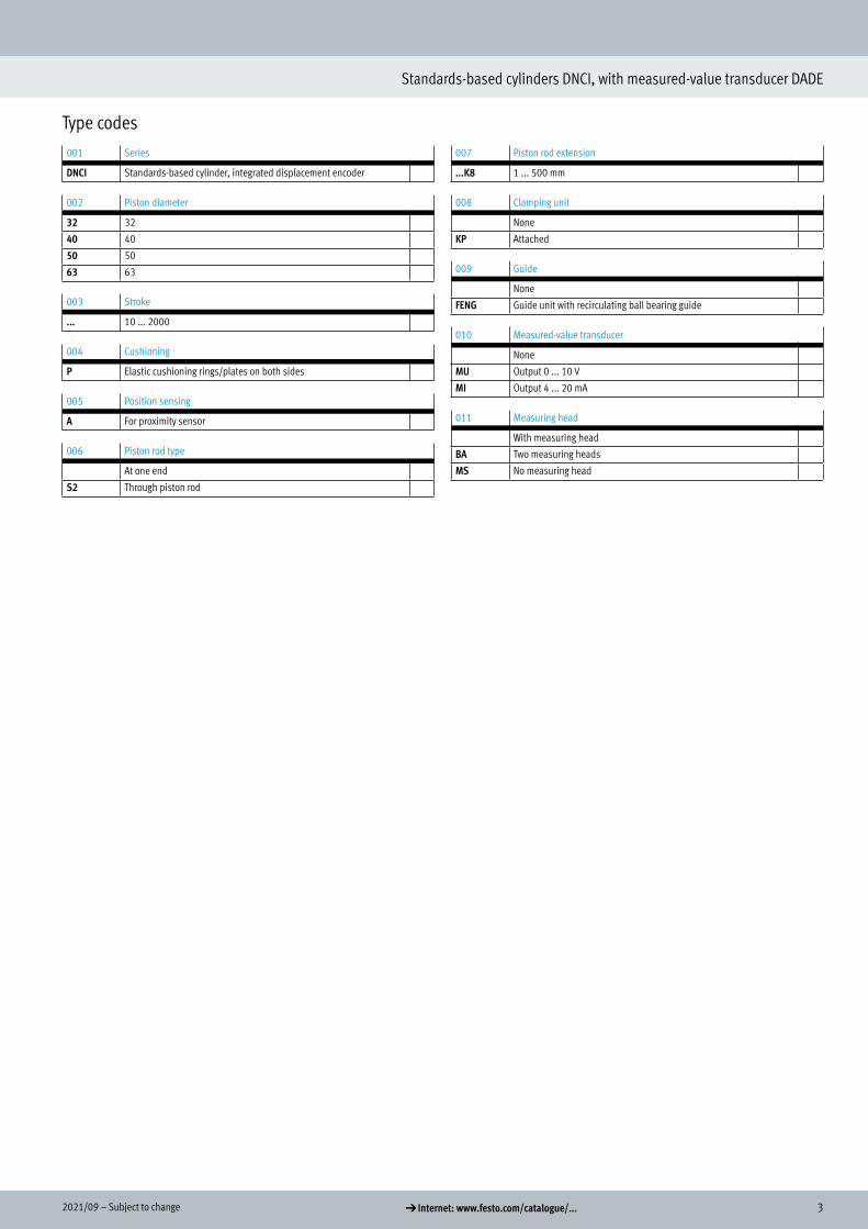
Type codes001 Series
DNCI Standards-based cylinder, integrated displacement encoder
002 Piston diameter
32 32
40 40
50 50
63 63
003 Stroke
... 10 ... 2000
004 Cushioning
P Elastic cushioning rings/plates on both sides
005 Position sensing
A For proximity sensor
006 Piston rod type
At one end
S2 Through piston rod
007 Piston rod extension
...K8 1 ... 500 mm
008 Clamping unit
None
KP Attached
009 Guide
None
FENG Guide unit with recirculating ball bearing guide
010 Measured-value transducer
None
MU Output 0 ... 10 V
MI Output 4 ... 20 mA
011 Measuring head
With measuring head
BA Two measuring heads
MS No measuring head
Type codes

4 d Internet: www.festo.com/catalogue/... Subject to change – 2021/09
Standards-based cylinders DNCI, with measured-value transducer DADE
Peripherals overview
1
2
3
4
6
9
11
12
5
7
8
10
12
13
14
15
527
26
25
24
28
17
18
10
16
16
19
20
21
22
2
3
5
4
23
AccessoriesType Description a Page/Internet
[1] Adapter kit1)
DPNCFor connecting two cylinders with identical piston diameter to form a multi-position cylinder dpnc
[2] Foot mountingHNC
For mounting the drive on the bearing and end caps hnc
[3] Flange mountingFNC
For mounting the drive on the bearing and end caps fnc
[4] Trunnion flangeZNCF/CRZNG
For swivelling movements of the drive on the bearing or end caps trunnion flange
[5] Trunnion supportLNZG/CRLNZG
– lnzg
1) Not with variant S2
Peripherals overview

52021/09 – Subject to change d Internet: www.festo.com/catalogue/...
Standards-based cylinders DNCI, with measured-value transducer DADE
Peripherals overview
AccessoriesType Description a Page/Internet
[6] Swivel flange1)
SNCFor swivelling movements of the drive on the end cap snc
[7] Clevis foot1)
LSNGWith spherical bearing lsng
[8] Clevis foot1)
LSNSGWeld-on, with spherical bearing lsnsg
[9] Swivel flange1)
SNCSFor swivelling movements of the drive on the end cap, with spherical bearing sncs
[10] Clevis foot1)
LBG– lbg
[11] Swivel flange1)
SNCLFor swivelling movements of the drive on the end cap sncl
[12] Swivel flange1)
SNCBFor swivelling movements of the drive on the end cap sncb
[13] Clevis foot1)
LNG/CRLNG– lng
[14] Clevis foot1)
LSNWith spherical bearing lsn
[15] Trunnion flange kitDAMT
For swivelling movements of the drive damt
[16] Rod eyeSGS/CRSGS
With spherical bearing sgs
[17] Right-angle clevis footLQG
– lqg
[18] Rod clevisSGA
With male thread sga
[19] Coupling pieceKSG
To compensate for radial deviations ksg
Coupling pieceKSZ
For cylinders with a non-rotating piston rod to compensate for radial deviations ksz
[20] Rod clevisSG/CRSG
Permits a swivelling movement of the cylinder in one plane sg
[21] Self-aligning rod couplerFK/CRFK
To compensate for radial and angular deviations fk
[22] AdaptersAD
For a suction cup with connection attachments ad
[23] Guide unit2)
FENGFor protecting standards-based cylinders against rotation at high torques 12
[24] Mounting kitSMB-8-FENG
For mounting proximity switches SME/SMT-8 in combination with guide unit FENG smb-8-feng
[25] Slot coverABP-5-S
For protecting the sensor cables and the sensor slots from contamination abp
[26] Proximity switchSME/SMT-8
Can be integrated in the cylinder profile barrel proximity switch
[27] Push-in fittingQS
For connecting tubing with standard O.D. qs
[28] Measured-value transducerMU, MI
Converts sensor signals of the standards-based cylinder DNCI into a voltage signal of 0 ... 10 V and/or a current signal of 4 ... 20 mA
15
1) Not with variant S2
2) Guide unit FENG-KF must be attached to the piston rod so that backlash is eliminated
6 d Internet: www.festo.com/catalogue/... Subject to change – 2021/09
Standards-based cylinders DNCI, with measured-value transducer DADE
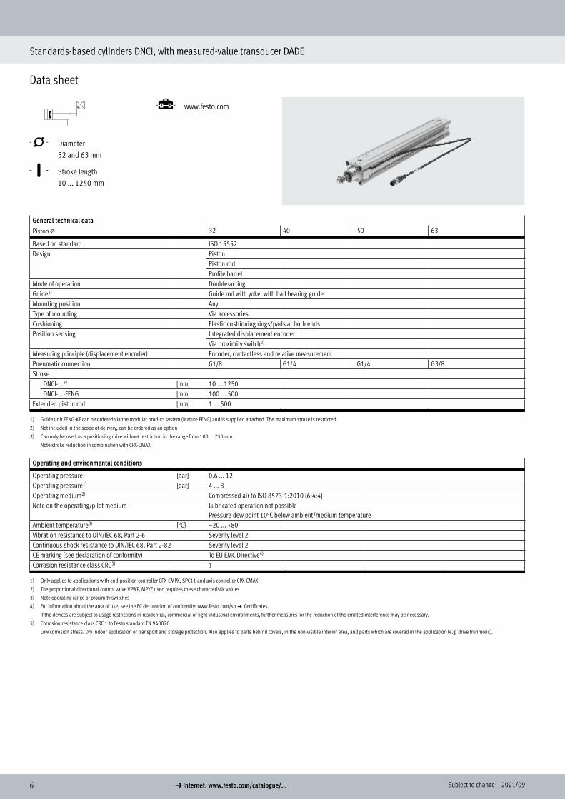
Data sheet
-N- Diameter 32 and 63 mm
-T- Stroke length 10 ... 1250 mm
-É- www.festo.com
General technical data
Piston @ 32 40 50 63
Based on standard ISO 15552Design Piston
Piston rodProfile barrel
Mode of operation Double-actingGuide1) Guide rod with yoke, with ball bearing guideMounting position AnyType of mounting Via accessoriesCushioning Elastic cushioning rings/pads at both endsPosition sensing Integrated displacement encoder
Via proximity switch2)
Measuring principle (displacement encoder) Encoder, contactless and relative measurementPneumatic connection G1/8 G1/4 G1/4 G3/8Stroke
DNCI-...3) [mm] 10 ... 1250DNCI-...-FENG [mm] 100 ... 500
Extended piston rod [mm] 1 ... 500
1) Guide unit FENG-KF can be ordered via the modular product system (feature FENG) and is supplied attached. The maximum stroke is restricted.
2) Not included in the scope of delivery, can be ordered as an option
3) Can only be used as a positioning drive without restriction in the range from 100 ... 750 mm.
Note stroke reduction in combination with CPX-CMAX
Operating and environmental conditions
Operating pressure [bar] 0.6 ... 12Operating pressure1) [bar] 4 ... 8Operating medium2) Compressed air to ISO 8573-1:2010 [6:4:4]Note on the operating/pilot medium Lubricated operation not possible
Pressure dew point 10°C below ambient/medium temperatureAmbient temperature3) [°C] –20 ... +80Vibration resistance to DIN/IEC 68, Part 2-6 Severity level 2Continuous shock resistance to DIN/IEC 68, Part 2-82 Severity level 2CE marking (see declaration of conformity) To EU EMC Directive4)
Corrosion resistance class CRC5) 1
1) Only applies to applications with end-position controller CPX-CMPX, SPC11 and axis controller CPX-CMAX
2) The proportional directional control valve VPWP, MPYE used requires these characteristic values
3) Note operating range of proximity switches
4) For information about the area of use, see the EC declaration of conformity: www.festo.com/sp a Certificates.
If the devices are subject to usage restrictions in residential, commercial or light-industrial environments, further measures for the reduction of the emitted interference may be necessary.
5) Corrosion resistance class CRC 1 to Festo standard FN 940070
Low corrosion stress. Dry indoor application or transport and storage protection. Also applies to parts behind covers, in the non-visible interior area, and parts which are covered in the application (e.g. drive trunnions).
Data sheet
Technical data
72021/09 – Subject to change d Internet: www.festo.com/catalogue/...
Standards-based cylinders DNCI, with measured-value transducer DADE
Data sheet
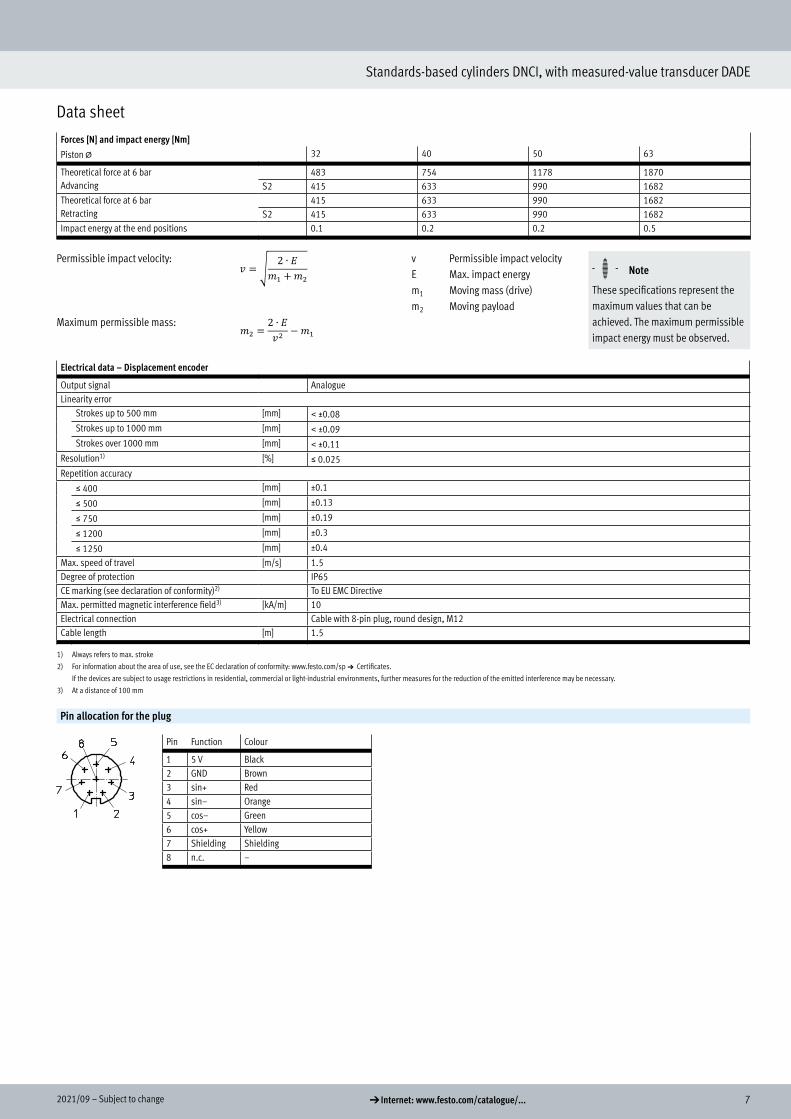
Forces [N] and impact energy [Nm]
Piston @ 32 40 50 63
Theoretical force at 6 barAdvancing
483 754 1178 1870S2 415 633 990 1682
Theoretical force at 6 barRetracting
415 633 990 1682S2 415 633 990 1682
Impact energy at the end positions 0.1 0.2 0.2 0.5
Permissible impact velocity:
Maximum permissible mass:
v Permissible impact velocityE Max. impact energym1 Moving mass (drive)m2 Moving payload
H- - Note
These specifications represent the maximum values that can be achieved. The maximum permissible impact energy must be observed.
Electrical data – Displacement encoder
Output signal AnalogueLinearity error
Strokes up to 500 mm [mm] < ±0.08Strokes up to 1000 mm [mm] < ±0.09Strokes over 1000 mm [mm] < ±0.11
Resolution1) [%] š 0.025Repetition accuracy
š 400 [mm] ±0.1
š 500 [mm] ±0.13
š 750 [mm] ±0.19
š 1200 [mm] ±0.3
š 1250 [mm] ±0.4
Max. speed of travel [m/s] 1.5Degree of protection IP65CE marking (see declaration of conformity)2) To EU EMC DirectiveMax. permitted magnetic interference field3) [kA/m] 10Electrical connection Cable with 8-pin plug, round design, M12Cable length [m] 1.5
1) Always refers to max. stroke
2) For information about the area of use, see the EC declaration of conformity: www.festo.com/sp a Certificates.
If the devices are subject to usage restrictions in residential, commercial or light-industrial environments, further measures for the reduction of the emitted interference may be necessary.
3) At a distance of 100 mm
Pin allocation for the plug
Pin Function Colour
1 5 V Black2 GND Brown3 sin+ Red4 sin– Orange5 cos– Green6 cos+ Yellow7 Shielding Shielding8 n.c. –
𝑣𝑣𝑣𝑣 = �2 ∙ 𝐸𝐸𝐸𝐸
𝑚𝑚𝑚𝑚1 +𝑚𝑚𝑚𝑚2
𝑚𝑚𝑚𝑚2 =2 ∙ 𝐸𝐸𝐸𝐸𝑣𝑣𝑣𝑣2
− 𝑚𝑚𝑚𝑚1

8 d Internet: www.festo.com/catalogue/... Subject to change – 2021/09
Standards-based cylinders DNCI, with measured-value transducer DADE
Data sheet
Weight [g]
Piston @ 32 40 50 63
DNCI-...Product weight with 0 mm stroke 521 853 1319 1914Additional weight per 10 mm stroke 30 44 62 71
Moving mass with 0 mm stroke 95 175 316 383Additional weight per 10 mm stroke 8 14 23 23
DNCI-...-S2 – Through piston rod Product weight with 0 mm stroke 586 981 1553 2165Additional weight per 10 mm stroke 39 60 87 96
Moving mass with 0 mm stroke 155 164 297 364Additional weight per 10 mm stroke 17 30 48 48
DNCI-...-K8 – Additional weight with piston rod extensionAdditional weight per 10 mm stroke 8 14 23 23
DNCI-...-KP – Additional weight with clamping unitProduct weight 234 394 700 1147
DNCI-...-FENG – Additional weight with guide unitProduct weight with 0 mm stroke 1530 2370 4030 5410Additional weight per 10 mm stroke 18 32 50 62
MaterialsSectional view
1 2 3
Standards-based cylinder
[1] Piston rod High-alloy steel[2] Cylinder barrel Anodised aluminium[3] Bearing/end caps Die-cast aluminium– Dynamic seals Polyurethane TPE-U– Static seals NBR
Note on materials RoHS-compliant
Displacement encoder– Sensor housing Polyacetal– Cable sheath Polyurethane– Plug housing Polybutylene terephthalate– Mounting plate Polyacetal– Screws for mounting plate Steel
Materials
92021/09 – Subject to change d Internet: www.festo.com/catalogue/...
Standards-based cylinders DNCI, with measured-value transducer DADE
Data sheet
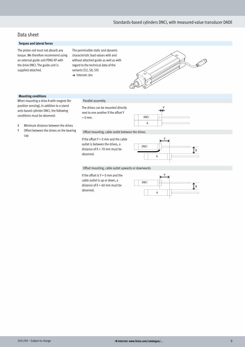
Torques and lateral forces
The piston rod must not absorb any torque. We therefore recommend using an external guide unit FENG-KF with the drive DNCI. The guide unit is supplied attached.
The permissible static and dynamic characteristic load values with and without attached guide as well as with regard to the technical data of the variants (S2, S8, S9)a Internet: dnc
Mounting conditionsWhen mounting a drive A with magnet (for position sensing), in addition to a stand-ards-based cylinder DNCI, the following conditions must be observed:
X Minimum distance between the drivesY Offset between the drives on the bearing
cap
Parallel assembly
The drives can be mounted directly next to one another if the offset Y = 0 mm. DNCI
A
Offset mounting, cable outlet between the drives
If the offset Y > 0 mm and the cable outlet is between the drives, a distance of X > 70 mm must be observed.
DNCI
A
Offset mounting, cable outlet upwards or downwards
If the offset is Y > 0 mm and the cable outlet is up or down, a distance of X > 60 mm must be observed.
DNCI
A

10 d Internet: www.festo.com/catalogue/... Subject to change – 2021/09
Standards-based cylinders DNCI, with measured-value transducer DADE
Data sheet
Dimensions Download CAD data a www.festo.comBasic version
[1] Socket head screw with female thread for mounting components
[2] Hole for securing the earthing for self-tapping M4 screw according to DIN 7500
[3] Sensor slot for proximity switch SME/SMT-8
[4] Magnetic measuring band+ = plus stroke length
S2 – Through piston rod
+ = plus stroke length++ = plus 2x stroke length
S2/KP – Through piston rod with clamping unit
+ = plus stroke length++ = plus 2x stroke length
K8 – Extended piston rod
Dimensions

112021/09 – Subject to change d Internet: www.festo.com/catalogue/...
Standards-based cylinders DNCI, with measured-value transducer DADE
Data sheet
@
[mm]
AM A2max.
B@
d11
BG D1@f9
D2 D7@
E EE G H1
32 22 500 30 16 20 M5 3.7 45 G1/8 28 6740 24 500 35 16 24 G1/8 3.7 54 G1/4 33 8850 32 500 40 17 30 G1/8 3.7 64 G1/4 33 10763 32 500 45 17 38 G1/8 3.7 75 G3/8 40.5 123
@
[mm]
KK L1 L2 L3 L5 L9 MM@f8
PL RT T1 TG
32 M10x1.25 18 94 45 14 22.5 12 15.6 M6 8 32.540 M12x1.25 21.3 105 53 16 27 16 14 M6 8 3850 M16x1.5 26.8 106 67 20 27 20 14 M8 8 46.563 M16x1.5 27 121 76 24 33 20 17 M8 8 56.5
@ VA VD WH ZJ ZM ß1 ß2 ß3
[mm] KP KP
32 4 10 26 120 165 148 193 10 16 640 4 10.8 30 135 188 167 220 13 18 650 4 14.3 37 143 210 183 250 17 24 863 4 14.5 37 158 234 199 275 17 24 8
12 d Internet: www.festo.com/catalogue/... Subject to change – 2021/09
Standards-based cylinders DNCI, with measured-value transducer DADE
Data sheet
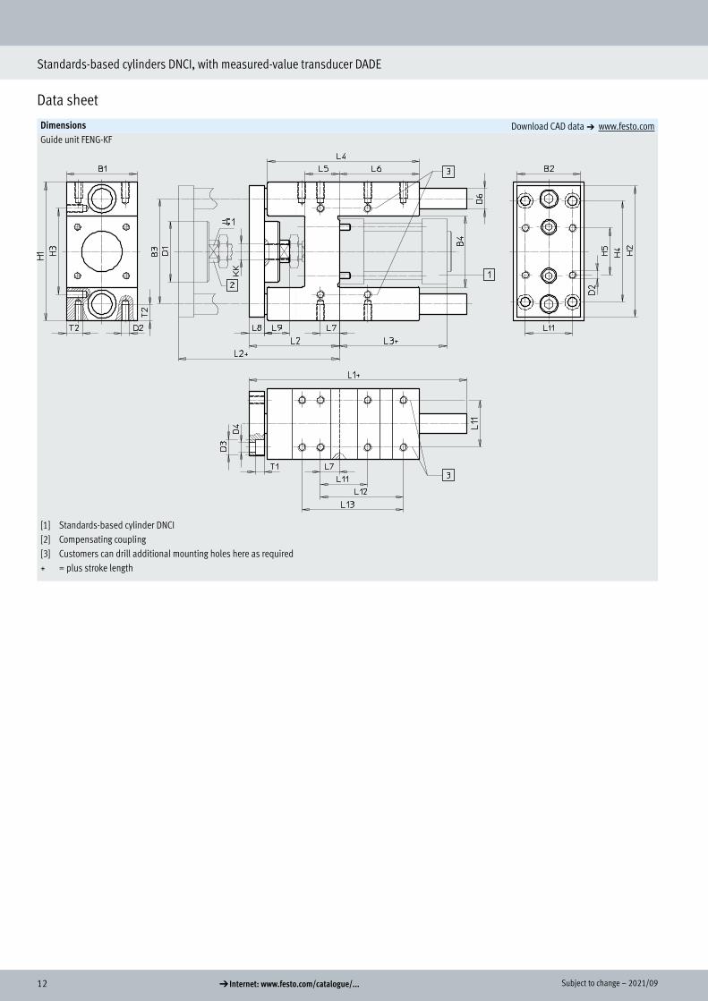
Dimensions Download CAD data a www.festo.comGuide unit FENG-KF
[1] Standards-based cylinder DNCI[2] Compensating coupling[3] Customers can drill additional mounting holes here as required+ = plus stroke length
132021/09 – Subject to change d Internet: www.festo.com/catalogue/...
Standards-based cylinders DNCI, with measured-value transducer DADE
Data sheet
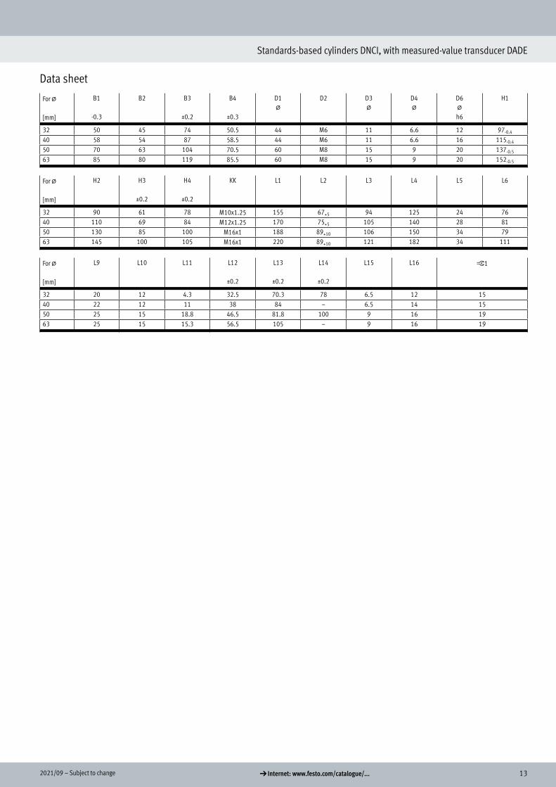
For @
[mm]
B1
-0.3
B2 B3
±0.2
B4
±0.3
D1@
D2 D3@
D4@
D6@h6
H1
32 50 45 74 50.5 44 M6 11 6.6 12 97-0.4
40 58 54 87 58.5 44 M6 11 6.6 16 115-0.4
50 70 63 104 70.5 60 M8 15 9 20 137-0.5
63 85 80 119 85.5 60 M8 15 9 20 152-0.5
For @
[mm]
H2 H3
±0.2
H4
±0.2
KK L1 L2 L3 L4 L5 L6
32 90 61 78 M10x1.25 155 67+5 94 125 24 7640 110 69 84 M12x1.25 170 75+5 105 140 28 8150 130 85 100 M16x1 188 89+10 106 150 34 7963 145 100 105 M16x1 220 89+10 121 182 34 111
For @
[mm]
L9 L10 L11 L12
±0.2
L13
±0.2
L14
±0.2
L15 L16 ß1
32 20 12 4.3 32.5 70.3 78 6.5 12 1540 22 12 11 38 84 – 6.5 14 1550 25 15 18.8 46.5 81.8 100 9 16 1963 25 15 15.3 56.5 105 – 9 16 19
14 d Internet: www.festo.com/catalogue/... Subject to change – 2021/09
Standards-based cylinders DNCI, with measured-value transducer DADE
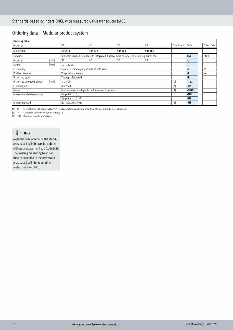
Ordering data – Modular product system
Ordering table
Piston @ 32 40 50 63 Conditions Code Enter code
Module no. 535411 535412 535413 535414
Function Standards-based cylinder with integrated displacement encoder, non-rotating piston rod DNCI DNCI
Piston @ [mm] 32 40 50 63 -...Stroke [mm] 10 ... 1250 -...Cushioning Elastic cushioning rings/pads at both ends -P -PPosition sensing Via proximity switch -A -APiston rod type Through piston rod -S2Piston rod extended at front [mm] 1 ... 500 [1] -...K8Clamping unit Attached [2] -KPGuide Guide unit with ball guide on the sensor head side [3] -FENGMeasured-value transducer Output 0 ... 10 V -MU
Output 4 ... 20 mA -MIMeasuring head No measuring head [4] -MS
[1] K8 In combination with piston rod type S2, the piston rod is only extended at the front (the side facing the measuring head).
[2] KP Can only be combined with piston rod type S2.
[3] FENG Maximum stroke length 500 mm.
H- - Note
[4] In the case of repairs, the stand-ards-based cylinder can be ordered without a measuring head (code MS).The existing measuring head can then be installed in the new stand-ards-based cylinder (operating instructions for DNCI).
Ordering data – Modular product system

152021/09 – Subject to change d Internet: www.festo.com/catalogue/...
Standards-based cylinders DNCI, with measured-value transducer DADE
Data sheet
Measured-value transducerDADE-MVC-010DADE-MVC-420(Order code MU, MI)
The measured-value transducer con-verts sensor signals of the stand-ards-based cylinder DNCI into a volt-age signal of 0 ... 10 V and/or a current signal of 4 ... 20 mA. These signals can be evaluated by a PLC with an appro-priate signal input.
General technical data
Type of mounting With through-holeMounting position AnyShort circuit current rating YesReverse polarity protection YesDiagnostic function Display via LED
General electrical data
Analogue output [V] 0 ... 10 (as per EN 61131-2)[mA] 4 ... 20 (as per EN 61131-2)
Nominal operating voltage [V DC] 24 ±25%Residual ripple [%] 4 (at 50 Hz)Current consumption at nominal operating voltage
[mA] 20 ... 30
Switching logic at outputs PNPSwitching logic at inputs PNPDebounce time at inputs [ms] 3Linearity error FS 0.2%
Operating and environmental conditions
Ambient temperature [°C] 0 ... 55Degree of protection IP65Relative humidity 95% non-condensingCE marking (see declaration of conformity) To EU EMC Directive
To EU RoHS DirectiveKC marking KC EMCCorrosion resistance class CRC1) 1Product weight [g] 128Note on material for housing Polybutylene terephthalate
1) Corrosion resistance class CRC 1 to Festo standard FN 940070
Low corrosion stress. Dry indoor application or transport and storage protection. Also applies to parts behind covers, in the non-visible interior area, and parts which are covered in the application (e.g. drive trunnions).
Accessories
Measured-value transducer

16 d Internet: www.festo.com/catalogue/... Subject to change – 2021/09
Standards-based cylinders DNCI, with measured-value transducer DADE
Data sheet
Dimensions Download CAD data a www.festo.com
Pin allocationPLC interface Measuring system interface
Pin Function Cable colour Pin Function
1 24 V White 1 Ub2 Analogue measurement signal Brown 2 0 V3 Reference output Green 3 Signal sine +4 0 V measurement signal Yellow 4 Signal sine -5 Reference input Grey 5 Signal cosine -6 Calibration input Pink 6 Signal cosine +7 Ready output Blue 7 Screening / earth8 0 V power supply and inputs/outputs Red 8 –
Ordering data Description Part no. Type
Measured-value transducerWith voltage signal 0 ... 10 V 542117 DADE-MVC-010With current signal 4 ... 20 mA 542118 DADE-MVC-420
Accessories Data sheets a Internet: sim
Connecting cable PLC connecting cable (length 2 m) 525616 SIM-M12-8GD-2-PUPLC connecting cable (length 5 m) 525618 SIM-M12-8GD-5-PU