standard specifications for construction of...
TRANSCRIPT
STANDARD SPECIFICATIONS
FOR
CONSTRUCTION
OF
WATER AND SEWER FACILITIES ___________________
PUBLIC WORKS DEPARTMENT OXFORD, MISSISSIPPI 38655
DIRECTOR OF PUBLIC WORKS BART ROBINSON
PREPARED IN 2007-2008 BY: BART ROBINSON, P.E. REVISED 2011 CITY OF OXFORD DEPARTMENT OF PUBLIC WORKS OXFORD, MS 38655
CITY OF OXFORD, MISSISSIPPI
Standard Specifications for Water and Sewer Line
Construction
As authorized by Section 21-19-25 of the Mississippi Code of 1972, the City of Oxford,
Mississippi, has prepared regulations governing the installation of all water and/or sewer lines or
related facilities which are to be dedicated to, and maintained by, the City of Oxford, Mississippi.
Accordingly, the specifications contained within this booklet represent a consolidation of numerous
regulations, codes, and ordinances of the City of Oxford pertaining to the design and construction of
water and/or sewer lines or related facilities.
It is the express intent of these regulations that the City of Oxford will accept for
maintenance only such water and/or sewer lines, and related appurtenances, which are deemed to be
necessary for the protection of the public health, safety, and general welfare of the City of Oxford.
Only in instances where the Mayor and Board of Aldermen find, that due to the circumstances
involved, that acceptance and maintenance by the City of Oxford would best serve the public
interest, shall any water and/or sewer lines, or related appurtenances, be accepted for maintenance by
the City of Oxford, Mississippi. Any extension of a water line to be owned by the city to serve fire
protection for a multi-unit development shall be constructed in a location as determined by the City
Engineer. The City shall not accept for maintenance any water lines in a multi-unit development
that are not strictly intended for fire protection. Service lines for water and sewer shall be owned
and maintained by the individual property owners and extended at the expense of the individual
property owner to right-of-ways or easements owned by the City of Oxford.
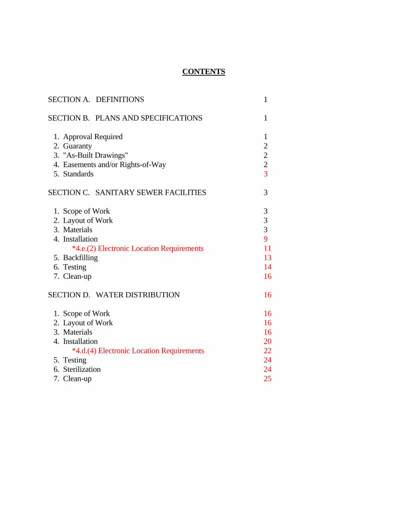
CONTENTS
SECTION A. DEFINITIONS 1 SECTION B. PLANS AND SPECIFICATIONS 1 1. Approval Required 1 2. Guaranty 2 3. "As-Built Drawings" 2 4. Easements and/or Rights-of-Way 2 5. Standards 3 SECTION C. SANITARY SEWER FACILITIES 3 1. Scope of Work 3 2. Layout of Work 3 3. Materials 3 4. Installation 9 *4.e.(2) Electronic Location Requirements 11 5. Backfilling 13 6. Testing 14 7. Clean-up 16 SECTION D. WATER DISTRIBUTION 16 1. Scope of Work 16 2. Layout of Work 16 3. Materials 16 4. Installation 20 *4.d.(4) Electronic Location Requirements 22 5. Testing 24 6. Sterilization 24 7. Clean-up 25
Department of Public Works, City of Oxford, Mississippi G:\Standard\Documents\TechSpec\2011 Modified City Water and Sewer Specifications.DOC October 2011
1
CITY OF OXFORD, MISSISSIPPI
STANDARD SPECIFICATIONS FOR WATER AND SEWER LINE CONSTRUCTION
SECTION A. DEFINITIONS For the purpose of these regulations, certain words or terms used herein shall be interpreted as follows: 1. City - the City of Oxford, Mississippi. 2. City Engineer - The duly authorized and appointed City Engineer of the City of
Oxford, Mississippi. 3. Developer - Any person, firm, corporation of other entity proposing to construct
water and/or sewer lines or related facilities which are to be dedicated to, and maintained by the City of Oxford, Mississippi. The term "Developer" shall also include any person, firm, corporation, or other entity employed by the developer to perform the actual construction and installation of the water and/or sewer lines or related facilities described herein.
4. Engineer - The registered professional engineer in charge of the design, layout, and
construction of the water and/or sewer lines or related facilities described herein. 5. Plans and Specifications - Such drawings, sketches, wording, or other documents
necessary to clearly describe the design, location, and installation of the water and/or sewer lines described herein.
6. Standard Sanitary Sewer and Water Works Detail Sheets -A set of drawings prepared
by the City of Oxford detailing graphically certain standards prescribed by these regulations.
SECTION B. PLANS AND SPECIFICATIONS 1. APPROVAL REQUIRED: All plans and specifications for construction of water
and/or sewer lines or related facilities shall be prepared by a registered professional engineer licensed to practice in the State of Mississippi. Such plans and specifications shall be presented to the City Engineer for review and approval prior to start of any type of construction. The City Engineer may require such changes or modifications as are necessary to make the plans and specifications comply with the requirements of these regulations. The City Engineer may also require such modifications that in his opinion lessen or ease the maintenance for the City of
Department of Public Works, City of Oxford, Mississippi G:\Standard\Documents\TechSpec\2011 Modified City Water and Sewer Specifications.DOC October 2011
2
Oxford. Upon final approval by all city departments, the developers shall submit three complete sets of construction plans and specifications to the City Engineer.
2. GUARANTY: The developer shall guarantee all materials and equipment furnished
and work performed for a period of one (1) year from the date of final acceptance by the Mayor and Board of Aldermen. The Developer shall warrant and guarantee for a period of one (1) year from the date of final acceptance that the completed system is free from all defects due to faulty materials or workmanship and the Developer shall promptly make such corrections as may be necessary by reason of such defects including the repair of any damage to other parts of the system resulting from such defects. The City will give notice of such observed defects with reasonable promptness. In the event that the Developer should fail to make such repairs, adjustments, or other work that may be necessary by such defects, the City may perform such repairs or adjustments and charge the Developer the cost thereby incurred.
3. "AS-BUILT" DRAWINGS: Upon completion of the water and/or sewer lines and
related facilities and approval and acceptance by the City, the Developer shall prepare and deliver one (1) complete set of "as-built" drawings to the City Engineer. Such "as-built" drawings shall clearly depict the exact location, size, and type of facilities installed, including, but not limited to: size of pipe, size and location of all valves, stub-outs, location and flow lines of all manholes, clean-outs, fire hydrants, lift stations, force mains, and widths of all easements.
4. All developers/developments will be required to perform an underground video
inspection of all sewer lines to be dedicated to the City of Oxford. Two copies of the video on CD will be supplied to the City of Oxford by the developer. Twenty-four (24) hours notice shall be given to the City Engineer prior to beginning the video inspection so that a representative from the City can be on site if possible.
5. EASEMENTS AND/OR RIGHTS-OF-WAY: Upon completion of the water and/or
sewer lines and related facilities, and at the time of their acceptance by the City of Oxford, the Developer shall have prepared and executed permanent easements or deeds of right-of-way to the City of Oxford. The minimum width for any water or sewer line easement shall be twenty (20) feet, provided however, that easements wider than twenty feet may be required by the City Engineer in areas of deep cuts or other special situations. All easements or deeds of rights-of-way shall be properly and accurately described by legal description, and in a form approved by the City Attorney. All such easements or deeds of right-of-way shall be presented to the Mayor and Board of Aldermen for their approval and acceptance.
Department of Public Works, City of Oxford, Mississippi G:\Standard\Documents\TechSpec\2011 Modified City Water and Sewer Specifications.DOC October 2011
3
6. STANDARDS: The "Sanitary Sewer and Water Works Detail" sheets as prepared by the City Engineer of the City of Oxford, Mississippi, and on file in the office of said City Engineer, are hereby made a part of these regulations by reference, and shall be incorporated into these regulations as if written and copied at length herein. In the case of a discrepancy between the “Detail” sheets and these specifications, the specifications shall govern. In any instance, the City Engineer should be notified of the discrepancy as soon as it becomes known.
SECTION C. SANITARY SEWER FACILITIES 1. SCOPE OF WORK: The work to be performed under these regulations shall consist
of furnishing all labor, tools, equipment and materials, and performing all operations necessary for construction of sanitary sewer gravity lines, manholes, force mains and pumping stations. Specifications for construction of the sanitary sewers and pumping stations are as follows.
2. LAYOUT OF WORK: a. Layout of Work: The Engineer shall provide all control points and
benchmarks necessary to layout the work. For sewers, control points will be provided at each manhole where the line turns.
b. Verifications: The City Engineer may make checks as the work
progresses to verify lines and grades established by the Developer and to determine the conformity of the completed work, as it progresses, with the plans and specifications.
3. MATERIALS: All gravity flow pipe shall be a minimum of eight (8) inches in
diameter, unless the City Engineer determines a larger size is necessary. All stub outs shall be a minimum of six (6) inches in diameter. Materials for construction and installation of the work included herein shall conform to the following specifications.
a. Sewer Pipe and Fittings: Gravity sewer pipe and fittings shall be
PVC or ductile iron as set forth in these regulations. All pipe and fitting shall be made of the best materials and shall be free of cracks or other imperfections, which will, in the judgement of the City Engineer, render them unsuitable for use. Curved pipes or bends, branches, tees and plugs shall be equal in all essential respects to the straight pipe of the same diameter.
(1) Ductile Iron: Ductile iron sewer pipe shall be Class 50 or 51,
manufactured and tested in accordance with ASA 21.51. Ductile
Department of Public Works, City of Oxford, Mississippi G:\Standard\Documents\TechSpec\2011 Modified City Water and Sewer Specifications.DOC October 2011
4
iron pipe shall have a push-on-joints and meet ANSI/AWWA C151/A21.51. Rubber gaskets shall be factory installed and meet ANSI/AWWA C111/A21.11. All Ductile Iron pipe shall be cement-mortar lined in accordance with ANSI/AWWA C104/A21.4.
(2) Polyvinyl Chloride (PVC): PVC pipe for force mains shall
conform to Commercial Standard CS-256-63 for Type 1120 material made to SDR 21 dimensions. Pressure class rating shall be 200 psi. Either rubber gasket or solvent weld joints may be used. If rubber gasket joints are used, the manufacturer must be approved by the City Engineer prior to installation. Fittings shall be ridged PVC, Type I, Schedule 40, Commercial Standard CS-207. All PVC pipe and fittings shall be approved and bear the seal of the National Sanitation Foundation.
PVC pipe and fittings for gravity mains shall meet or exceed ASTM Specifications D-3034 Type PSM Polyvinyl chloride (PVC) sewer pipe. Sewer shall be made to SDR 26 dimensions and have a pipe stiffness of 115 psi. Pipes shall be bell and spigot. The joint shall meet or exceed ASTM D-3212 for joints for drain. All gaskets shall be factory installed.
b. Casing Pipe: Casing pipe for highway and railroad crossing shall conform to ASTM Designation A-53, Schedule 20 or heavier.
c. Manholes and Cleanouts: Manholes shall be constructed of precast
concrete, poured-in-place concrete or integral precast concrete. Dimension and details shall be as set forth in these regulations. Cast iron manhole rings and covers, as depicted by these regulations, shall be mounted on the top of each manhole at a specified finish grade.
(1) Precast Manholes: Precast manhole sections shall conform to
ASTM Designation C-478-95a. Manhole sections shall have steps that are permantely attached to the wall of the manhole and meet all applicable codes as set forth by ANSI/AWWA and the Occupational Safety and Health Standards. Care shall be taken to ensure that a bottom is poured and finished flush to the flow line of the pipe to ensure proper drainage. Manhole sections shall be joined with two layers of bitumen sealant meeting Commercial Standard CS-102-B or CS-102-DO-B. Lift holes in each section shall be sealed water
Department of Public Works, City of Oxford, Mississippi G:\Standard\Documents\TechSpec\2011 Modified City Water and Sewer Specifications.DOC October 2011
5
tight with non-shrinking grout. The manufacturer for each section incorporated into this project shall furnish a test report.
(2) Poured-in-Place Manholes: Poured-in-place concrete manholes
shall attain a 28 day compressive strength of 3,000 psi. The concrete shall be dense, non-porous, water tight, with no honeycomb and finished in a neat and workmanlike manner. Care shall be taken to ensure that a bottom is poured and finished flush to the flow line of the pipe to ensure proper drainage.
(3) Rings and Covers: Manhole rings and covers installed in traffic
areas shall conform to ASTM Specifications A-48 and shall be suitable for heavy duty traffic. The same type manhole rings and covers shall be used throughout the same project. Rings and covers shall be make Vulcan V-1099 Type 17, or approved equal. All manholes shall be 2” thick and capable of receiving a riser.
(4) Manhole Seals: A positive gasket seal connector shall be
installed to seal the manhole to the connector, and to seal the connector to the sewer pipe, at each pipe and manhole connection. The seal between the manhole and connector may be made by casting the connector integrally with the manhole wall, or by mechanical means such as a power sleeve or press wedge. The seal between the connector and sewer pipe may be made by mechanical means, such as a take-up clamp, press wedge, or by compression of the resilient material against the outside of the pipe. The gasket seal connector assembly shall conform to ASTM C923, and shall be equal to "Econoseal", "Press Wedge", or PSX Positive Seal as manufactured by Press-Seal Gasket Corporation, Ft. Wayne, Indiana.
d. Concrete Pier Pipe Support: Concrete piers shall be constructed of
structural concrete, which shall attain a 28-day compressive strength of 3,000 psi. The concrete shall have no honeycomb and be finished in a neat workmanlike manner. A professional engineer shall design concrete and reinforcing steel for the pier support. Design shall be stamped by a Professional Engineer registered with the Mississippi State Board of Registration for Professional Engineers & Land Surveyors.
e. Sewer Lift Stations: The design, type, manufacturer, and capacity of
all sewer lift stations shall be as required by the City Engineer, and shall be installed in strict accordance with the manufacturer’s instructions.
Department of Public Works, City of Oxford, Mississippi G:\Standard\Documents\TechSpec\2011 Modified City Water and Sewer Specifications.DOC October 2011
6
(1) Access Drive / Driveway: An all weather access drive shall be required for all pumping stations. Materials allowed for surface include limestone (3/4” and Down) and Asphalt Surface. Where constant maintenance of limestone will be required, an asphalt drive will be required.
(2) Wetwell: The wetwell shall be as specified in Section C, Sanitary
Sewer Facilities (Item 3.c. - Manholes and Cleanouts) and installed accordingly. Shall have a steel access door placed over the wetwell. The wetwell shall be located in the approximate center of the floor to allow access from all sides for maintenance and repairs.
(3) Lift Station Pumps: Shall be minimum of Duplex Design. Pumps
shall be non-clog submersible pumps with a self-engaging auto-coupling assembly to eliminate the need to enter the “Wet Well” as manufactured by Chicago, Essco, Hydramatic, Gorman Rupp, Fairbanks Morris or Flight.
(4) Electrical, Controls and Control Panel: All electrical work shall
be in accordance with the most recent requirements of the National Electrical Code, National Electrical Safety Code, International Building Code, the local electric power utility and the City of Oxford Public Works Department. Controls shall be in a NEMA 3R enclosure as manufactured by Hoffman, Electromate or approved equal. The control shall be “Duplex Pump Control Panel” as manufactured by Control System, Inc. of Jackson, MS or approved equal.
(5) Pump Discharge Piping: Shall be of materials in current use by
the City of Oxford. (a) Ductile Iron Pipe: Discharge piping shall be ductile iron
with flanged ends and conform to ANSI/AWWA C115/A21.15. Pipe shall be rated for 250 psi working pressure. Bolts, nuts, and rubber gaskets shall be furnished and comply with requirements of Appendix A of AWWA C115. The exterior of the pipe shall be coated with an asphaltic coating approximately 1 mil thick. The interior of the pipe shall have a cement-mortar lining in accordance with ANSI/AWWA C104/A21.4. Ductile iron pipe shall be Thickness Class 51.
Department of Public Works, City of Oxford, Mississippi G:\Standard\Documents\TechSpec\2011 Modified City Water and Sewer Specifications.DOC October 2011
7
(b) Check Valve: The check valve shall be the swing type spring and lever design conforming to AWWA C508. The valve shall be iron body, bronze mounted, with flanged ends. The valve shall have a rubber faced disc with O-ring sealed stuffing box. The valve shall be equipped with an adjustable spring tension to control opening and closing of the clapper. Valves shall be rated for 175 psig operating pressure and tested to 350 psig. Valves shall be Clow or M&H by Kennedy Valve Company, or approved equal.
(c) Gate Valve: Gate valves shall be the resilient wedge type
conforming to AWWA C509. Valves shall have an iron body with flanged ends and rated for 220 psig working pressure. Interior and exterior surfaces of the valve shall be fusion epoxy coated in accordance with AWWA C550. The valve shall have an iron wedge fully encapsulated in molded rubber with no exposed iron. The valve shall be equipped with a handwheel for operation, a non-rising stem, and have a triple O-ring sealed stuffing box. The valve shall be M&H, or approved equal.
(d) Ductile Iron Fittings: Discharge pipe fittings shall be
flanged ductile iron fittings conforming to ANSI/AWWA C110/A21.10. All flanged ductile iron fittings shall be rated for working pressure of 250 psi. Bolts, nuts, and rubber gaskets shall be furnished and comply with requirements of Appendix A of AWWA C110. Fittings shall have a asphaltic coating approximately 1 mil thick. The interior of the fittings shall have a cement mortar lining in accordance with ANSI/AWWA C104/A21.4.
(e) Pressure Gauge: A 2 ½” diameter pressure gauge shall be
installed at the pump head discharge to allow accurate measurement of the discharge pressure.
(6) Building / Pump House: Lift station building shall be constructed
in conformance with the International Building Code. Stick Framed (must have a brick exterior) or Masonary Block construction will be required. Building shall be 14’ X 14’ minimum with 8’ ceilings minimum (larger size may be required dependent on
Department of Public Works, City of Oxford, Mississippi G:\Standard\Documents\TechSpec\2011 Modified City Water and Sewer Specifications.DOC October 2011
8
the capacity of the station and size of pumps and wetwell. A special exception may be granted by the City Engineer to allow for a smaller size building based on the size of the pumps and wetwell.)
(a) Concrete: All concrete for slabs and footings and
miscellaneous construction shall be Class “B” as specified by the Mississippi Standard Specifications for State Aid Road and Bridge Construction.
(b) Reinforcing Steel: All reinforcing steel shall be as specified by the Mississippi Standard Specifications for State Aid Road and Bridge Construction.
(c) Rafters, Ridge, Fascia, Cornice shall be #2 pine and span sized according to International Building Code. An I-beam shall be installed directly over the wet well and capable of supporting 2000 pounds or 1.5 times the weight of the pump, whichever is greater.
(d) Inside Ceiling and Inside Walls shall be 4’ X 8’ X ½” wafer board and shall be painted.
(e) Insulation shall be placed in ceilings and walls (on wood construction). Provide a minimum of 3 and ½” (3 ½”) kraft-faced fiberglass insulation.
(f) Face Brick (on wood construction) shall be standard 2-1/4”x3-5/8”x7-5/8”.
(h) Exterior door shall be a metal double door, 6068, with door grill (louver) in both doors. Doors shall be equipped with keyed lockset acceptable for outside service.
(i) All buildings shall have an exhaust fan capable for 4 air changes per hour.
(j) All buildings must be equipped with two (2) interior lights and one (1) exterior floodlights. Interior lights shall be 8’ fluorescent tube lights.
(k) A frost proof water hydrant shall be located outside the building unless waived by special exception from the City Engineer.
(7) Additional Appurtenances: Additional appurtenances may be
required on a case-by-case basis. All plans must be approved by the City of Oxford.
Department of Public Works, City of Oxford, Mississippi G:\Standard\Documents\TechSpec\2011 Modified City Water and Sewer Specifications.DOC October 2011
9
4. INSTALLATION: Specifications for installation of the gravity sewer lines,
manholes and force mains are as follows: a. Excavation: The Developer shall perform all excavation of every
description and of whatever substance encountered to the depths indicated on the plans and specifications. During excavation, material suitable for backfilling shall be stockpiled in an orderly manner and at a sufficient distance from the bank of the trench or other excavation to avoid overloading of the banks and to prevent slides or cave-ins. All surplus excavation shall be disposed of in a neat and orderly manner. All excavations shall be kept dry and any water accumulating in excavations shall be removed.
b. Trenching: Trenches for gravity sewer lines and manholes shall be
excavated to the grade and on the line as shown in the plans. Force mains shall have a minimum cover of 36 inches and be installed in accordance with alignment as shown on the plans. Care shall be exercised not to undercut below specified grade except for removal of rock or other sharp or abrasive material. All areas of undercut shall be carefully tamped back to the satisfaction of the City Engineer. A cushion of four (4) inches of select material shall be maintained over said rock or sharp or abrasive material.
(1) Trenches shall be of only such width as necessary for proper
laying of the pipe. For gravity sewer, the net width of the trench at and below the top of the pipe shall be such as to leave at least six (6) but not more than twelve (12) inches on each side of the outside of the pipe.
(2) The sides of the trench shall be as nearly vertical as possible.
The bottom of the trench shall be carefully graded, formed and aligned before the pipe is laid. The bottom of the trench shall be rounded under each joint of pipe to conform to the shape of the pipe, and bell holes shall be cut so as to allow the body of the pipe a uniform contact and support throughout its entire length.
c. Sheeting, Bracing and Shoring: The Developer shall do all bracing,
sheeting, and shoring necessary to perform and protect all excavations as required for safety. Materials for sheet piling, sheeting, bracing, and shoring, shall be furnished and driven or set in place by the Contractor.
Department of Public Works, City of Oxford, Mississippi G:\Standard\Documents\TechSpec\2011 Modified City Water and Sewer Specifications.DOC October 2011
10
(1) All sheeting, sheet piling, braces or shores shall be driven or put
in place by men especially skilled in such work, and shall be so arranged that if practical, they may be withdrawn as the excavations are backfilled, without injury to the structure and its appurtenances and without injury to or settlement of adjacent structures and pavements. Sheeting, sheet piling, bracing and shores shall be withdrawn and removed as the excavations are being backfilled, except where and to such extent as the City Engineer shall order, in writing, that the same be left in place, or where the City Engineer shall permit the Developer to leave the same in place, at the Developer's own cost and request.
(2) In withdrawing sheeting and sheet piling, special care shall be
taken to insure that all voids or holes left by the plank as they are withdrawn are filled with satisfactory material and thoroughly rammed with thin tampers provided especially for the purpose.
(3) The Developer shall cut off any sheeting or sheet piling left in
place whenever and at such points as the City Engineer shall order and shall remove from the work the portion cut off.
d. Dewatering: The Developer shall perform all pumping and well
pointing necessary to maintain excavation in a dry state during the work.
e. Pipe Laying: The bottom of the trench shall be shaped to give
substantially uniform circumferential support to the lower fourth of each pipe. Pipe laying shall proceed up-grade with the spigot ends of bell-and-spigot pipe pointing in the direction of the flow. Each pipe shall be laid true to line and grade and in such manner as to form a close concentric joint with the adjoining pipe and to prevent sudden off-sets of the flow line. As the work progresses, the interior of the sewer shall be cleared of all dirt and superfluous materials of every description. Where cleaning after laying is difficult because of small pipe size, a suitable swab or drag shall be kept in the pipe and pulled forward past each joint immediately after the jointing has been completed. If the maximum width of the trench at the top of the pipe, specified above, is exceeded for any reason other than by direction, the Developer shall install such concrete cradling, pipe encasement, or other bedding as may be required to satisfactorily support the added load of the back fill. Trenches shall be kept free of water and pipe shall not be laid when the condition of the trench
Department of Public Works, City of Oxford, Mississippi G:\Standard\Documents\TechSpec\2011 Modified City Water and Sewer Specifications.DOC October 2011
11
or the weather is unsuitable for such work. At time when work is not in progress, open ends of pipe and fittings shall be securely and satisfactorily closed so that no trench water, earth, or other substance will enter the pipe or fittings.
(1) Concrete thrust blocks shall be installed for force mains at the
tees, crosses, caps, and plugs. (2) The contractor will furnish and install a coated, solid copper
tracer wire on all sewer lines, both conductive and non-conductive, in the trench alongside the pipe. Wire color will be green for all sewer lines. The wire gauge must be 14 gauge minimum and run continuously without splices for the full length of the service line. A locate marker sign must be placed at each end of the 500’ spool of tracer wire and at all other locations where a splice is necessary. All splices must be made above-ground, unless otherwise approved. A direct bury splice kit is required for all below-ground splices. The Public Works Deparment may require that a flush-mounted valve or meter box with a metal lid be used in place of marker signs in some areas to reduce visual clutter. The tracer wire shall daylight at the point of entry at the foundation of the building through PVC conduit and a blank box as a future contact point to locate the service. Tracer wire will be installed on all new sewer main installations in the street/roadway and will come to the surface at every manhole for termination.
a. For all gravity sewer manholes located in pavement, the tracer wire shall be run on the outside of the manhole and under the ring, leaving 4’ of slack wire inside of the hole. The tracer wire shall not run directly through the manhole.
b. For all high pressure sewer lines, the tracer wire shall be installed on each side of the air relief manhole and terminate on a post.
A separate tracer wire is required from the cleanout to the sewer manhole.
Department of Public Works, City of Oxford, Mississippi G:\Standard\Documents\TechSpec\2011 Modified City Water and Sewer Specifications.DOC October 2011
12
If the tracer wire is to be installed at the same time as the concrete is to be poured, the tracer wire must be enclosed in PVC conduit for protection.
f. Jointing: Pipe joints shall be made in accordance with the
manufacturer's instructions and with special care to avoid breakage. All pipe lengths shall be placed on exact line and grade before pushing home the joint. Pipe shall be pushed home with a constant and even force and shall not be jarred home by the momentum of a moving force that will place a shock load on the pipe already in place. Cement and lubricant shall be used as recommended by the manufacturer.
g. Road Crossing: Where gravity sewer mains or sewer force mains
cross State Highways, they shall be installed inside steel casing having an inside diameter large enough to accommodate the carrier pipe freely. The casing pipe shall be installed by the boring process. Casing pipe for gravity sewer shall be installed to line and grade as shown on the Contract Drawings or cut sheet. Care shall be taken to prevent damage to the roadway and any repairs necessary as a result of the operation shall be the responsibility of the Contractor.
Where sanitary sewer services or sanitary sewer mains cross-city streets or streets to be dedicated to the city curbs will be permanently marked or physically stamped with S by the developer. Minimum letter size shall be 3” in height and letters shall be visible from the centerline of street. The Engineer must be contacted and allowed to verify all locations before curbs are marked or stamped. During final inspection the developer may be asked to expose randomly selected crossings to see that the curb marks are accurately located.
h. Manholes:(1) Precast manhole sections without integral base
sections shall be installed by supporting the first section of the barrel on brick or concrete block and then pouring the concrete base to assure inbedding three (3) inches of the barrel in the concrete base. All precautions shall be taken to insure a water tight joint. Additional sections shall not be set until the base has reached its initial set. A fully watertight joint shall be constructed around the influent and effluent lines as specified in section 3.c.4. Care shall be taken to insure vertical alignment of the precast barrel sections.
Department of Public Works, City of Oxford, Mississippi G:\Standard\Documents\TechSpec\2011 Modified City Water and Sewer Specifications.DOC October 2011
13
(2) Manhole inverts shall be constructed true to line and grade. Where possible, inverts shall be constructed of half diameter pipe; otherwise, inverts shall be constructed of concrete with a smooth semi-circular shape and shall conform to the adjacent sewer pipe. Changes in direction of flow shall be made with a smooth curve of as large a radius as the manhole size will permit. The floor of the manhole outside the channels shall be smooth and shall slope toward the channels at approximately three (3) inches horizontally to one (1) inch vertically.
(3) Manhole rings and covers shall be installed to the grade as shown
by the plans and specifications or to that of the surrounding surface and shall be set and anchored in a bed of mortar.
i. Separation Between Water and Sewer Lines: It is essential to
maintain adequate clearance between water supply and sewage lines. A minimum separation of ten (10) feet horizontally and/or eighteen (18) inches vertically below shall be maintained. If such separation is not possible, special precautions, as directed by the City Engineer, shall be taken by the Developer to prevent contamination of waterworks facilities. The water line shall always be placed at a higher elevation than the sewer line.
5. BACKFILLING: When the pipe has been laid and jointed as specified herein, the
pipe shall immediately be bedded in the trench and made secure against movement by backfilling the trench to the springline of the pipe by hand with approved backfill material and compacting to 95% relative density. From the springline to a point two (2) feet above the top of the pipe, selected backfill material shall be placed in eight (8) inch loose layers and 95% percent of the standard proctor or relative density, depending upon the material to be compacted. Final backfill except under roadways the backfill shall be placed in lifts not exceed (12) inch layers and compacted to 90% standard proctor. Under roadways backfill shall be compacted to 95% standard proctor.
After the trenches have been properly backfilled, all excess dirt shall
be removed from the streets and roadways and from private property so that pavement may be replaced and properties cleaned up. In open fields and unimproved property the excess dirt shall be spread out or used to fill low spots, such spreading or filling being done in such a manner that will not obstruct surface drainage. The material for backfilling, unless otherwise specified, shall be excavation taken
Department of Public Works, City of Oxford, Mississippi G:\Standard\Documents\TechSpec\2011 Modified City Water and Sewer Specifications.DOC October 2011
14
from trenches and shall be free from stones, broken concrete or asphalt larger than three (3) inches in diameter. It shall be free from all perishable and objectionable materials such as rubbish, forms, blocks, wires or other unsuitable material. These methods of backfilling shall apply in all cases except where specifically altered or changed by the City Engineer. The Developer shall be totally responsible for the condition of the trenches at all times prior to final acceptance. He shall make frequent inspection of the trenches and repair all settled areas as they occur. All soft or dangerous trenches shall be marked or barricaded and red-lighted at night for protection to the public. The backfill material shall have reached maximum practical density (at least 90% Standard Proctor) before final acceptance.
6. TESTING: Gravity sewer lines shall be thoroughly cleaned and checked for
obstructions by balling each line from manhole to manhole. All sand, silt and debris shall be removed from each manhole. Each line shall then be checked by mirrors and sunlight or by a light flashed between manholes. Each line shall then be video inspected as part of the testing. The developer will furnish the city two copies of the video on CD. Twenty-four (24) hours notice shall be given to the City Engineer prior to beginning the video inspection so that a representative from the City can be on site if possible. The developer at his expense shall repair any horizontal and/or vertical displacement, or any other defects observed.
a. Hydrostatic testing shall be an acceptable method of leakage test only when
ground water level is above the level of the pipe throughout the length being tested. Tests for water tightness shall be made by the contractor in the presence of the Engineer, and the sewer and connections shall not leak. Under the exterior normal ground water pressure in excess of a rate of two hundred (200) gallons per day, per inch diameter, per mile. The tests and measurements of infiltration shall be conducted in a manner approved by the Engineer.
Exfiltration testing is to be made only in dry areas, or when the ground water level above the pipe is suitably low. The sewer and connections shall not leak in excess of a rate of two hundred (200) gallons per day, per inch diameter, per mile. The exfiltration testing shall be made by filling a length of sewer pipe or two feet (2’) higher than the ground water level, whichever is greater with a maximum internal pipe pressure at the lowest end, not to exceed twenty-five (25”) of water.
Twenty percent (20%) of all manholes shall be tested for exfiltration by filling with water up to the bottom of the manhole cone (top of the full
Department of Public Works, City of Oxford, Mississippi G:\Standard\Documents\TechSpec\2011 Modified City Water and Sewer Specifications.DOC October 2011
15
manhole diameter). The manholes shall not leak in excess of a rate of 0.232 inches of vertical depth per day, per foot of vertical depth of manhole (1.818 gallons per day per foot of vertical depth of manhole). Two additional manholes shall be tested for every manhole that fails the test. All sewer lines, sewer connections, and manholes that do not meet the infiltration/exfiltration test requirements shall be repaired and retested until they pass the tests.
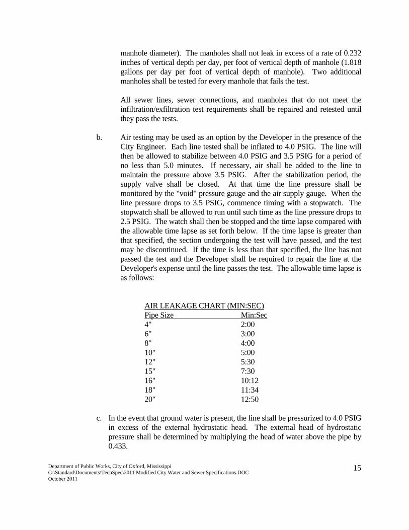
b. Air testing may be used as an option by the Developer in the presence of the City Engineer. Each line tested shall be inflated to 4.0 PSIG. The line will then be allowed to stabilize between 4.0 PSIG and 3.5 PSIG for a period of no less than 5.0 minutes. If necessary, air shall be added to the line to maintain the pressure above 3.5 PSIG. After the stabilization period, the supply valve shall be closed. At that time the line pressure shall be monitored by the "void" pressure gauge and the air supply gauge. When the line pressure drops to 3.5 PSIG, commence timing with a stopwatch. The stopwatch shall be allowed to run until such time as the line pressure drops to 2.5 PSIG. The watch shall then be stopped and the time lapse compared with the allowable time lapse as set forth below. If the time lapse is greater than that specified, the section undergoing the test will have passed, and the test may be discontinued. If the time is less than that specified, the line has not passed the test and the Developer shall be required to repair the line at the Developer's expense until the line passes the test. The allowable time lapse is as follows:
AIR LEAKAGE CHART (MIN:SEC) Pipe Size Min:Sec 4" 2:00 6" 3:00 8" 4:00 10" 5:00 12" 5:30 15" 7:30 16" 10:12 18" 11:34 20" 12:50
c. In the event that ground water is present, the line shall be pressurized to 4.0 PSIG in excess of the external hydrostatic head. The external head of hydrostatic pressure shall be determined by multiplying the head of water above the pipe by 0.433.
Department of Public Works, City of Oxford, Mississippi G:\Standard\Documents\TechSpec\2011 Modified City Water and Sewer Specifications.DOC October 2011
16
7. CLEAN-UP: The job site shall be maintained in a neat, workmanlike and sanitary
manner during construction. As portions of the work are completed, all excess excavation, bricks, concrete, pipe and other materials shall be removed and disposed of by the developer in a manner acceptable to the City Engineer.
SECTION D. WATER DISTRIBUTION 1. SCOPE OF WORK: The work shall include the furnishing, transporting and
stringing of pipe; furnishing, transporting, storage and protection of valves, fire hydrants, fittings, and all other materials that may be required for construction of the facility; ditching, shoring, backfill, installation of pipe, valves, fire hydrants and fittings; testing, sterilization, clean-up and all other operations necessary to complete the work in accordance with the specifications hereinafter set forth.
2. LAYOUT OF WORK: a. Layout of Work: The Engineer shall provide all control points and
benchmarks necessary to layout the work. b. Verifications: The City Engineer may make checks as the work
progresses to verify lines and grades established by the Developer and to determine the conformity of the completed work, as it progresses, with the plans and specifications.
3. MATERIAL: All materials used which will be in contact with potable water shall be
non-toxic and approved for use in potable water systems by AWWA, U.S. EPA, Underwriters Laboratory, National Sanitation Foundation, or other appropriate organization. The contractor shall incorporate only materials indicated by the approved construction drawings. All defective materials shall be replaced. Materials stored outdoors shall be on suitable supports to prevent direct contact with ground surface and storm water.
a. Pipe shall be ductile iron and shall be push-on joint and conform to
ANSI/AWWA C151/A21.51. Rubber gasket joints shall conform to ANSI/AWWA C111/A21.11. The ductile iron pipe shall be designed for 350 psi working pressure for laying Condition Type 1 and shall be ANSI Thickness Class 350. All pipe shall have an inside lining of cement- mortar conforming with ANSI A21.4 (AWWA C104). The exterior of the pipe shall be coated with an asphaltic coating approximately 1 mil thick. All water mains shall
Department of Public Works, City of Oxford, Mississippi G:\Standard\Documents\TechSpec\2011 Modified City Water and Sewer Specifications.DOC October 2011
17
be eight (8) inches or larger, unless specifically authorized by the City Engineer.
b. Fittings shall be ductile iron and shall be mechanical joint unless
specifically authorized by the City Engineer. Fittings shall conform to ANSI/AWWA C153/A21.53. Rubber gaskets joints shall conform to ANSI/AWWA C111/A21.11. Fittings shall have an asphaltic coating approximately 1 mil thick. The interior of the fittings shall have a cement mortar lining in accordance with ANSI/AWWA C104/A21.4. All fittings shall have a working pressure of 350 psi. All fittings shall be of domestic manufacture and if requested, the manufacturer shall furnish the City Engineer with certified test certificates stating that all materials furnished are in accordance with the above specifications.
d. Casing Pipe for highway, railroad and ditch crossings shall conform
to ASTM Designation A-53, Schedule 20 or heavier. e. Gate Valves shall comply with AWWA Specifications C-509 or C-
515, as manufactured by M&H, or Clow 6100 Series and meeting the following design specifications:
All gate valves are to be resilient seated type with iron body. Gate
valves shall have a operating pressure of 250 psi and be hydrostatically tested at 500 psi. The interior and exterior surfaces of the body and bonnet shall be coated in accordance with ANSI/AWWA C550. Valves shall have a non-rising stem with a 2” nut and the wedge shall iron and completely encapsulated in a resilient material.
f. Tapping Sleeves shall be Fast Tap Tapping Sleeves. Tapping sleeves
are to be all stainless steel or stainless with a carbon steel flange. Fast Tap Tapping Sleeves shall be as manufactured by Ford model Fast-XXX-XA or approved equal. Sleeves shall be rated for minimum 200 psi working pressure and equipped with a test plug.
g. Tapping Valves shall be resilient seated type with iron body. Gate
valves shall have a operating pressure of 250 psi and be hydrostatically tested at 500 psi. The interior and exterior surfaces of the body and bonnet shall be coated in accordance with ANSI/AWWA C550. Valves shall have a non-rising stem with a 2” nut and the wedge shall iron and completely encapsulated in a resilient material. The valves shall be furnished with tapping sleeve
Department of Public Works, City of Oxford, Mississippi G:\Standard\Documents\TechSpec\2011 Modified City Water and Sewer Specifications.DOC October 2011
18
sized to ANSI B16.1 flanged end with centering ring. Outlet side of valve shall be mechanical joint with accessories as required to conform to AWWA C-111. Tapping valves shall be M&H 4751, Clow C-515 or C-509, or approved equal.
h. Valve Boxes shall be cast iron two piece, screw type, 5-1/4 inch
shaft. Valves shall contain the word “WATER” on the valve cover. Contractor shall supply boxes with the correct base for all valves and in correct lengths for field conditions.
i. Restraint Glands for Ductile Iron Pipe shall be manufactured of high
strength ductile iron conforming to the requirements of ASTM A536, Grade 65-45-12. Restraint for standardized mechanical joints shall be incorporated in the design of the follower gland and shall impart multiple points of wedge action against the pipe, increasing its resistance as the pressure increases. The assembled joint shall maintain its flexibility after burial and shall maintain its integrity by a controlled and limited expansion of each joint during the wedging action. Wedges shall be contoured to properly fit on the pipe, and shall be manufactured of ductile iron, heat treated to a minimum hardness of 370 BHN. Dimensions of the glands shall be such that they can be used with the standardized mechanical joint bell and tee head bolts conforming to the requirements of ANSI/AWWA C111/A21.111 or ANSI/AWWA C153/A21.53 of latest version. The mechanical joint restraining device shall have a water working pressure rating of 250 psi minimum with a safety factor of at least 2:1 against separation when tested in a dead-end situation, and shall be Uni-Flange Series 1400, UFR 1400-DA-X-U, or approved equal.
j. Fire Hydrants shall comply with AWWA Specification C-502 and
shall be of the compression type, closing with the line pressure. The main valve opening shall be as shown on the "Standard Water Works Detail Sheet. The depth of bury shall be the same as that specified for the pipe. Installation shall be such that the "depth of bury" marking shall coincide with the existing ground line. Hydrants shall be furnished with a sealed oil reservoir located in the bonnet so that all threaded and bearing surfaces are lubricated when hydrant is operated. The hydrant shoe shall have at least two drain outlets. Size and type shoe shall be determined by the size and type of pipe used. Hydrants shall be furnished with a breakable feature that will break cleanly upon impact. This shall consist of a two part, breakable safety flange with a breakable stem coupling. Fire
Department of Public Works, City of Oxford, Mississippi G:\Standard\Documents\TechSpec\2011 Modified City Water and Sewer Specifications.DOC October 2011
19
hydrants shall be three way, M&H Style 129 or Clow Medallion Series. Size and threading of hydrant nozzles shall be the same as those presently being used by the Owner. All hydrants shall open in the same direction as those presently being used by the City, which is open left (counter-clockwise). Fire hydrants shall be yellow from the manufacturer.
k. Meter Boxes shall be installed at grade by the Developer, shall be
cast iron, and shall conform to AWWA Specifications. Boxes shall be the same type currently used by the City. Boxes shall be oval, measure approximately 19 ½” Long x 10½” Wide x 10” Deep for ¾” to 1” service lines. For service lines which are 1½” to 2”, boxes shall be oval and measure approximately 24” Long x 13 ¾” Wide x 13” Deep.
l. Service Saddles shall be all brass double strap saddles designed for
ductile iron pipe, Ford 202B-xxx-Tap or approved equal. Saddles shall have an AWWA tapered thread. Saddles shall conform to all applicable sections of ANSI/AWWA C800.
m. Corporations Stops shall be ball corporation valves and shall have
AWWA tapered thread inlet by grip joint outlet for CTS copper or polyethylene tubing. Stops shall be Ford FB 1000 Ballcorp, and shall comply with all applicable sections of ANSI/AWWA C800.For service lines ¾” to 1”, stops shall be FB 1000-xG. For service lines 1 ½” to 2”, stops shall be FB 500-x.
n. Copper Service Tubing shall conform to ASTM B88, ASTM B88M,
and shall be Type K.
o. Curb Valves shall be ball valves with inlets for CTS polyethylene or copper service tubing and female iron pipe thread outlets. Curb valves shall be Ford 1-XXX, Ford B41-xxxWG or approved equal and shall comply with all applicable sections of ANSI/AWWA C800.
o. Concrete shall develop a compressive strength of 3,000 pounds per
square inch at 28 days. p. Asphalt for street repair shall meet Mississippi State Highway
Department specifications for Hot Bituminous Pavement, Type SC-1.
Department of Public Works, City of Oxford, Mississippi G:\Standard\Documents\TechSpec\2011 Modified City Water and Sewer Specifications.DOC October 2011
20
4. INSTALLATION: a. Excavation - The Developer shall perform all excavation of every
description and of whatever substances encountered to the depth specified in the Plans or as directed by the City Engineer. The bottom of all trenches shall be carefully shaped, graded, and aligned in accordance with the instructions of the City Engineer and to his complete satisfaction before any pipe is placed. Care shall be taken not to excavate below the depth specified. However, in the event excessive excavation should occur, the bottom of the trench shall be filled back to grade with approved material and thoroughly compacted. All trenches shall be excavated to a depth to maintain minimum cover over the installed pipe as follows:
(1) 36" for ordinary pipe (2) 42" under existing creeks (3) Within highway and railway rights of way, trenching will be
in strict accordance with the permit, with particular attention paid to both line and grade and as may be directed by the State Highway Department or its designated representative.
Holes of ample size shall be cut under and around all joints to provide
adequate room for making joints and to assure that the barrel of the pipe rests uniformly and in continuos contact with the supporting ground for its entire length.
When rock is encountered, the Developer shall excavate to a depth at
least 4 inches below the required grade and backfill to grade with 4 inches of sand cushion.
Pipe shall not be laid when water is in the trench. The Developer
shall not excavate more trench than can be pumped dry by available pumping facilities.
If the established grade conflicts with other utilities, the water line
grade shall be changed to avoid the conflict. b. Sheeting and Bracing - The Developer shall furnish and place, to the
satisfaction of the City Engineer, such sheeting and bracing as may be required to support the sides of the trench and to protect the workmen and pipe or adjacent structures from injury by the sloughing or caving of the trenches. Approval of protective sheeting
Department of Public Works, City of Oxford, Mississippi G:\Standard\Documents\TechSpec\2011 Modified City Water and Sewer Specifications.DOC October 2011
21
and bracing by the City Engineer will not extend to the City Engineer any liability for such protective measures which later prove defective. This sheeting and bracing may be removed as the trench is backfilled, or may be left in place when necessary to prevent damage. In the event the sheeting or bracing is left in place, it shall not extend nearer than one (1) foot to the surface of the ground.
c. Backfilling Trenches - Backfilling shall be carefully performed and
the original surface restored. The trenches shall be backfilled with fine, loose earth, free from large clods or stones, carefully rammed until enough has been placed to provide a cover of not less than one (1) foot above the pipe. The remainder of the backfill material shall be placed in successive loose layers not to exceed 12 inches and compacted until a density of at least that of adjacent soil is attained. Whenever the trenches have not been properly filled, or if settlement occurs, they shall be refilled, smoothed off, and made to conform to the surface of the ground. Backfill in areas to be paved shall be made, as above specified, except that fill above pipes shall be deposited in layers not to exceed six (6) inches. Such fill shall be compacted with mechanical tampers so that, when completed, the compacted soil shall have a density of at least that of the undisturbed adjacent ground. Disposal of surplus material shall be the responsibility of the Developer.
d. Pipe Laying (1) Pipe, appurtenances, and fittings shall be laid to the line and grade established on the Plans. A minimum cover of 36 inches shall be maintained over all pipe. The bed for the pipe is to be shaped by either trimming the bottom of the trench or by placing excavated earth thereon and tamping so that each piece of pipe has uniform bearing. The trench shall be further excavated around each bell or hub, so that it will be entirely clear of the ground and leave ample room for making joints.
(2) The inside of the bells and the outside of the spigots shall be
thoroughly cleaned before they are placed. The inside of all pipe shall be thoroughly swabbed to insure that the pipe is clean and free of obstructions and foreign matter until the work is completed.
(3) Where pipe laying ceases at the end of the day or for any cause,
the end of the pipe shall be securely closed in order to prevent the entrance of water, mud, or any other objectionable matter.
Department of Public Works, City of Oxford, Mississippi G:\Standard\Documents\TechSpec\2011 Modified City Water and Sewer Specifications.DOC October 2011
22
(4) The contractor will furnish and install a coated, solid copper
tracer wire on all water lines, both conductive and non-conductive, in the trench alongside the pipe. Wire color will be blue for water.
The wire gauge must be 14 gauge minimum and run continuously
without splices for the full length of the service line. A locate marker sign must be placed at each end of the 500’ spool of tracer wire and at all other locations where a splice is necessary. All splices must be made above-ground, unless otherwise approved. A direct bury splice kit is required for all below-ground splices. The Public Works Department may require that a flush-mounted valve or meter box with a metal lid be used in place of marker signs in some areas to reduce visual clutter.
The tracer wire shall daylight at the point of entry at the foundation of
the building through PVC conduit and a blank box as a future contact point to locate the service.
If the tracer wire is to be installed at the same time as the concrete is to be poured, the tracer wire must be enclosed in PVC conduit for protection.
Tracer wire will be installed on all new water main installations in the
street/roadway and will come to the surface at every fire hydrant for termination.
Depending on circumstances of a specific installation, the Public
Works Department may also require that tracer wire be run to curb boxes, cleanouts, or fire hydrants.
e. Making Joints - All joints shall be constructed in accordance with the
manufacturer's recommendations. f. Setting Fittings, Valves, Hydrants, etc. - All fittings, valves , valve
boxes, hydrants, and other appurtenances shall be set at the location indicated on the Plans.
g. Tapping Sleeves and Tapping Valves shall be installed at locations as
shown on the Plans. Care shall be taken not to damage the existing pipe outside the limits of the tapping sleeve. A cast iron valve box shall be installed on the tapping valve.
Department of Public Works, City of Oxford, Mississippi G:\Standard\Documents\TechSpec\2011 Modified City Water and Sewer Specifications.DOC October 2011
23
h. Service Assemblies shall consist of a corporation stop, curb stop and
other appurtenances shown on the "Standard Water Works Detail Sheets". They shall be installed in a good and workmanlike manner at the places designated on the Plans or as directed by the City Engineer.
i. Pavement Repair shall consist of preparation and compaction of
subgrade and base course, construction of a six (6) inch thick concrete slab with a minimum of 2 inches of hot mix asphalt constructed to match existing pavement. If existing pavement is concrete, the concrete slab shall match the existing pavement. Width of the concrete slab shall be a minimum of two (2) feet wider than the width of the ditch with a minimum of one (1) foot being supported by undisturbed base material.
j. Railroad and Road Crossing - Where water mains cross state or
federal highways or railroads, they shall be installed inside steel casing having an inside diameter large enough to accommodate the water main freely. The casing shall be placed in a manner acceptable and approved by the State Highway Department or the railroad company. Installation can be accomplished by dry boring a hole to receive the casing pipe and jacking the casing through the road bed. Care shall be used to prevent damage to the road bed or surface, and any repairs necessary as a result of the operation shall be the responsibility of the Developer.
Upon completion of the installation of casing, the carrier pipe shall be
installed in the casing in such a manner as to avoid any undue stress or damage to the pipe or its coating. The carrier pipe shall be free of tension at all points in the casing.
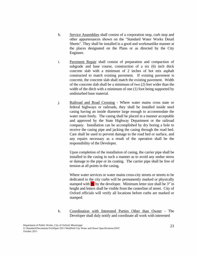
Where water services or water mains cross-city streets or streets to be dedicated to the city curbs will be permanently marked or physically stamped with W by the developer. Minimum letter size shall be 3” in height and letters shall be visible from the centerline of street. City of Oxford officials will verify all locations before curbs are marked or stamped.
k. Coordination with Interested Parties Other than Owner - The
Developer shall duly notify and coordinate all work with interested
Department of Public Works, City of Oxford, Mississippi G:\Standard\Documents\TechSpec\2011 Modified City Water and Sewer Specifications.DOC October 2011
24
parties such as the State Highway Department, and any railroad company involved. No work which affects these interested parties will commence until satisfactory coordination has been achieved.
5. TESTING: After the pipe is laid and the line flushed, it shall be filled with water
with care being exercised to expel all air from the pipe. During the test period all pipe, valves, fittings, and joints shall be examined carefully for defects. Any observed leaks or defective pipe shall be satisfactorily repaired or replaced, and the test repeated until the section tested is within the limits prescribed hereinafter. The entire distribution system or parts thereof shall be tested under a hydrostatic pressure of 150 psi for a period of 2 hours if joints are exposed, or for a 24 hour period if joints are covered. An approved calibrated meter through which all of the water required to maintain test pressure shall be pumped shall measure leakage. All testing shall be performed in the presence of the City Engineer or his designated representative, who shall be notified at least 24 hours in advance of the start of the test.
The Developer shall furnish the pump, pipe, connections, fittings, gages, meters, and
all other necessary apparatus and shall furnish all labor and work required to make the tests. All costs of testing shall be borne by the Developer and testing operations shall remain in operation until approved by the City Engineer. All pressure and leakage testing shall comply with AWWA C-600 and AWWA C-605, latest revision.
6. STERILIZATION: After completion of the distribution system installation and
testing, the water lines shall be thoroughly flushed to remove dirt and foreign matter and be sterilized in accordance with the requirements of the State Board of Health.
When the pipe is sterilized, samples of water shall be extracted from the system for
examination by the Mississippi State Department of Health to determine whether the system is free of organisms of the Coli Aerogenes group. If the samples submitted contain such organisms, the piping shall be disinfected again and redisinfected, if necessary, until the Developer secures approval from the Mississippi State Department of Health. The Developer at no expense to the City of Oxford shall furnish all materials and labor required for complete sterilization of the system.
7. CLEAN-UP: In areas where the water mains have been backfilled, the Developer
shall clear the right of way and surrounding areas, and shall dispose of all waste materials and debris resulting from his operations. He shall fill and smooth holes and ruts and shall repair all miscellaneous and unclassified ground damage done by
Department of Public Works, City of Oxford, Mississippi G:\Standard\Documents\TechSpec\2011 Modified City Water and Sewer Specifications.DOC October 2011
25
him, and shall restore the ground to such stable and suitable conditions as may be reasonable required, consistent with the condition of the ground prior to construction. All grassed or sodded areas disturbed during construction shall be restored to a condition equal to or better than that which existed prior to construction.