2014 saws construction specifications
TRANSCRIPT

8/21/2019 2014 SAWS Construction Specifications
http://slidepdf.com/reader/full/2014-saws-construction-specifications 1/461
Specifications
For
Water and Sanitary Sewer
Construction
April
2014

8/21/2019 2014 SAWS Construction Specifications
http://slidepdf.com/reader/full/2014-saws-construction-specifications 2/461
MISSION STATEMENT
THE MISSION OF THE SAN ANTONIO WATER SYSTEM IS TO
PROUDLY SERVE OUR CUSTOMERS AND HELP COMMUNITIES
FLOURISH WITH PLENTIFUL, QUALITY, AFFORDABLE WATERSERVICE. OUR VALUES ARE EXCELLENCE, INTEGRITY, AND
RESPECT. OUR VISION OF SUCCESS IS ACHIEVED THROUGH
PEOPLE, BEST-IN-CLASS PERFORMANCE, AND STRONG
PARTNERSHIPS.

8/21/2019 2014 SAWS Construction Specifications
http://slidepdf.com/reader/full/2014-saws-construction-specifications 3/461
3 April 2014
INTRODUCTION
THE STANDARD SPECIFICATIONS AND DRAWINGS ARE PROVIDED AS ATECHNICAL RESOURCE FOR ENGINEERING PROFESSIONALS FOR USE IN DESIGN
AND CONSTRUCTION OF WATER AND WASTEWATER PROJECTS MANAGED AND
CONTRACTED BY THE SAN ANTONIO WATER SYSTEM. AS DESIGN
PROFESSIONALS, THEY ASSUME RESPONSIBLITY FOR SELECTION, REFERENCE,AND APPROPRIATE APPLICATION OF THESE RESOURCES. THE STANDARD
SPECIFICATIONS AND STANDARD DRAWINGS OFFERED HERE CAN BE
AUGMENTED BY SUPPLEMENTAL SPECIFICATIONS AND MODIFIED DETAILSPRODUCED BY THE ASSIGNED OR CONTRACTED DESIGN PROFESSIONAL AND
APPROVED BY THE SAN ANTONIO WATER SYSTEM. THE SAN ANTONIO WATER
SYSTEM ACCEPTS NO LIABILITY FOR USE OF THESE RESOURCES. ANY PERSON
MAKING USE OF THE INFORMATION CONTAINED IN THESE FILES SHALL BESOLELY RESPONSIBLE FOR THEIR USE. THESE FILES ARE NOT INTENDED AS A
SUBSTITUTE FOR THE PROFESSIONAL JUDGEMENT OF A DESIGN PROFESSIONAL.
FOR REFERENCE, WE HAVE INCLUDED UNEDITED SPECIFICATIONS FROM THECITY OF SAN ANTONIO.
AT ANY TIME, THESE SPECIFICATIONS AND DRAWINGS MAY BE ALTERED ORSUPERSEDED BY THE GENERAL CONDITIONS, SPECIFIC CONDITIONS, OR
DRAWINGS WITHIN THE BID DOCUMENTS ISSUED FOR EACH PROJECT.
ALL “APROVED EQUAL” PARTS AND MATERIALS SHALL BE DIRECTLY IN
ACCORDANCE WITH SAWS’ MATERIAL SPECIFICATIONS WHICH CAN BE
FOUND IN SAWS’ WEBSITE. NO OUTSIDE MANUFACTURERS WILL BE USED
UNLESS DIRECTLY SPECIFIED IN THE CONTRACT DOCUMENTS.
COMMENTS AND/OR REVISIONS SHOULD BE MADE IN WRITING AND MAILED TO
THE FOLLOWING ADDRESS:
San Antonio Water System
Post Office Box 2449
San Antonio, Texas 78298-2449
Attn: David Maxwell, P.E.
Director of Pipeline Inspections

8/21/2019 2014 SAWS Construction Specifications
http://slidepdf.com/reader/full/2014-saws-construction-specifications 4/461
4 April 2014
Construction Specifications Item Number
Mobilization .................................................................................................................100Preparation of Right-of-Way .......................................................................................101
Recycled Water System ...............................................................................................110Flexible Base ................................................................................................................200Concrete (Natural Aggregate) ......................................................................................300
Reinforcing Steel .........................................................................................................301
Concrete Structures ......................................................................................................307
Trench Excavation Safety Protection...........................................................................550Excavation, Trenching and Backfill ............................................................................804
Reinforced Concrete Vaults .........................................................................................808
Reinforced Concrete Vaults for Metered Fireline Services .........................................809
Water Main Installation ...............................................................................................812Water Service for Firelines ..........................................................................................813
Ductile Iron Pipe ..........................................................................................................814Steel Pipe Installation ..................................................................................................816PVC (C-900, C-905 and C-909) Pipe Installation .......................................................818
Concrete Steel Cylinder Pipe Installation ....................................................................820
High Pressure Zone Distribution System .....................................................................821Customer's Water Yard Pipe ........................................................................................822
Directional Boring for Customer’s Water Yard Pipe ..................................................823
Water Service Supply Lines .........................................................................................824Valve Box Adjustments ...............................................................................................826
Gate Valves ..................................................................................................................828
Butterfly Valves ...........................................................................................................830
Cut-In-Tee ....................................................................................................................831Tapping Sleeves and Valves ........................................................................................832
Meter and Meter Box Installation ................................................................................833
Fire Hydrants ...............................................................................................................834
Grey-Iron and Ductile-Iron Fittings .............................................................................836Anchorage/Thrust Blocking and Joint Restraint ..........................................................839
Water Tie-Ins ...............................................................................................................840
Hydrostatic Testing Operations ...................................................................................841Blow-off Assemblies ...................................................................................................844
Gate, Fencing, and Property Marker Details ...............................................................845
Air Release Assemblies ...............................................................................................846
Disinfection ..................................................................................................................847Sanitary Sewers ............................................................................................................848
Sanitary Sewer Pipe Air and Deflection Testing .........................................................849
Sanitary Sewer Structures ............................................................................................850Adjusting Existing Manholes .......................................................................................851
Sanitary Sewer Manholes ............................................................................................852
Glass-Fiber Reinforced Polyester (FRP) Manholes .....................................................853Sanitary Sewer Laterals ...............................................................................................854
8/21/2019 2014 SAWS Construction Specifications
http://slidepdf.com/reader/full/2014-saws-construction-specifications 5/461
5 April 2014
Reconstruction of Existing Manholes ..........................................................................855
Jacking, Boring or Tunneling Pipe ..............................................................................856
Concrete Encasement, Cradles, Saddles, and Collars ..................................................858Vertical Stacks .............................................................................................................860
Abandonment of Sanitary Sewer Mains and Manholes ...............................................862
Bypass Pumping...........................................................................................................864Sewer Main Television Inspection...............................................................................866Sanitary Sewer System Cleaning .................................................................................868
Project Signs ................................................................................................................869
Pipe Bursting/Crushing Replacement Process .............................................................900Construction Safety and Health Program ....................................................................902
Construction QC/QA Program .....................................................................................903
Construction Phase Procedures ....................................................................................904
Water Use Accountability ............................................................................................906Service Line Break/Leak Repairs ..............................................................................1015
Water Main Break/Leak Repairs ...............................................................................1020
Slip-lining Sanitary Sewers........................................................................................1100Slip-lining Grout ........................................................................................................1101
Point Repairs and Obstruction Removals ..................................................................1103
Sanitary Sewer Service Stubs and Reconnections .....................................................1109
Progress Schedule ......................................................................................................1110Project Record Documents ........................................................................................1112
Pre-Construction Video .............................................................................................1114
Handling Asbestos Cement Pipe ................................................................................3000
NOTE:
1. Instructions to Bidders and General Conditions will be issued with Bid Documents foreach project. Questions may be directed to Contract Administration at (210) 233-3408.
2. Current Material Specifications are maintained by Quality Assurance Coordinator, Robert
Cruz, telephone number (210) 233-3274, or may be obtained through the SAWShomepage at http://www.saws.org.
3. Information about new Production standards may be obtained through the SAWS
homepage at http://www.saws.org.
Useful References:
1. American Water Works Association (AWWA) - http://www.awwa.org/
2. U.S. Environmental Protection Agency (EPA) - http:// epa.gov 3. City of San Antonio (COSA) - http://www.sanantonio.gov/
4. Texas Administrative Code (TAC) - http://www.sos.state.tx.us/tac/index.shtml
5. Texas Commission On Environmental Quality (TCEQ) - http://www.tceq.state.tx.us/ 6. Texas Department of Transportation (TxDOT) - http://www.txdot.gov/

8/21/2019 2014 SAWS Construction Specifications
http://slidepdf.com/reader/full/2014-saws-construction-specifications 6/461
San Antonio Water System Standard Specif ications for Construction
100-1 April 2014
ITEM NO. 100
MOBILIZATION
100.1
DESCRIPTION: This item shall govern the mobilization of personnel,equipment, and supplies at the project site in preparation for beginning work on
other contract items. Mobilization shall include, but is not limited to, themovement of equipment, personnel, material, supplies, etc. to the project site and
the establishment of office and other facilities necessary prior to beginning the
work. Examples of inclusive material are those typical of payment aspectsdesignated as large “EA” items (such as manholes, fire hydrants, water valves,
etc), or “LF” items such as (water or sewer main piping).
100.2 MEASUREMENT: Measurement of the Item, Mobilization, as specified herein,will be by the “Lump Sum,” as the work progresses.
100.3 PAYMENTS: Partial payments of the “Lump Sum” bid for mobilization will be
as follows: (The adjusted contract amount for construction items, as used below,is defined as the total contract amount, less the lump sum bid for Mobilization and
Preparing Right-Of-Way).
1. When 1% of the adjusted contract amount for construction items is earned,
50% of the ”Lump Sum” bid or 5% of the total contract, whichever is less,
will be paid.
2. When 5% of the adjusted contract amount for construction items is earned,
75% of the ”Lump Sum” bid or 10% of the total contract amount,whichever is less, will be deducted from the above amount.
3. When 10% of the adjusted contract amount for construction items is
earned, 90% of the ”Lump Sum” bid or 15% of the total contract amount,whichever is less, will be paid. Previous payments under this item will be
deducted from the above amount.
4. Payment for this line item will be reduced by half of the earned amount,until said documents are submitted and approved by SAWS: all material
submittals, Item No. 902, “ Safety and Health Program”, , Item No. 903,
Construction QC/QA Program,Item No. 1114,“Pre-ConstructionVideo”, and Item No.,1110 “Progress Schedule”,.
5. Upon completion of all work under this contract, payment for the
remainder of the “Lump Sum” bid for Mobilization will be made. NOTES: Cost for Insurance and Bond is inclusive to cost of Mobilization

8/21/2019 2014 SAWS Construction Specifications
http://slidepdf.com/reader/full/2014-saws-construction-specifications 7/461
San Antonio Water System Standard Specif ications for Construction
100-2 April 2014
Item.
6. Payment shall be made by the Inspector for approved materials stored on
the project site that are deemed necessary and required for the “PROJECTWORK” in accordance with all contract documents.
- End of Specification -

8/21/2019 2014 SAWS Construction Specifications
http://slidepdf.com/reader/full/2014-saws-construction-specifications 8/461
San Antonio Water System Standard Specif ications for Construction
101-1 April 2014
ITEM NO. 101
PREPARING RIGHT-OF-WAY
101.1
DESCRIPTION: This item shall govern preparing the right-of-way forconstruction operations by removing and disposing of all obstructions from theright-of-way and from designated easements where removal of such obstructions
is not otherwise provided for in the contract documents.
Such obstructions shall be considered to include, but not be limited to, remains of
houses or structures not completely removed by Contractor or others, foundations,floor slabs, concrete, brick, lumber, plaster, cisterns, septic tanks, basements,
abandoned utility pipes or conduits, equipment or other foundations, fences,
retaining walls, outhouses, shacks, and all other debris, as well as buried concrete
slabs, curbs, driveways and sidewalks.
This item shall also include the removable of trees, stumps, bushes, shrubs, brush,
roots, vegetation, logs, rubbish, paved parking areas, miscellaneous stone, brick,
drainage structures, manholes, inlets, abandoned railroad tracks, scrap iron and all
debris, whether above or below ground, except live utility facilities.
This item shall not govern the demolition of buildings by the use of explosives.
Such demolition work shall be governed by the use of a special specification
controlling the work.
It is the intent of this specification to provide for the removal and disposal of allobstructions to the new construction, together with other objectionable materials,
not specifically provided for elsewhere by the contract documents. .
Unless shown otherwise in the contract documents,, all fences along the right-of-
way which are damaged or removed temporarily by the Contractor shall bereplaced by the Contractor to an equal or better condition, at no additional cost to
the SAWS.
101.2 CONSTRUCTION METHODS: Areas designated in the contract documents
shall be cleared of all obstructions, vegetation, abandoned structures, etc., asdefined above, except trees or shrubs specifically designated by the engineer for
preservation. Trees and shrubs designated for preservation shall be carefully
trimmed as directed and shall be protected from scarring, barking, or other
injuries during construction operations. Exposed ends of pruned limbs shall betreated with an approved pruning material.
Unless otherwise indicated in the contract documents, all underground
obstructions shall be removed to the following depths:

8/21/2019 2014 SAWS Construction Specifications
http://slidepdf.com/reader/full/2014-saws-construction-specifications 9/461
San Antonio Water System Standard Specif ications for Construction
101-2 April 2014
1. In areas to receive embankment, 2 feet below natural finished grade.
2. In areas to be excavated, 2 feet below the lowest elevation of the
excavation;
3. All other areas, 2 feet below finished grade.
Holes remaining after removal of all obstructions, objectionable materials,vegetation, etc., shall be backfilled and tamped as directed by the Inspector, and
the entire area shall be bladed to prevent ponding of water and to provide
drainage. In areas that are to be immediately excavated, backfilling and blading
may be eliminated, if approved by the Inspector. Areas to be used as burrow sitesand material sources shall have all obstruction, objectionable materials,
vegetation, etc., removed to the complete extent necessary to prevent such
objectionable matter from becoming mixed with the material to be used in theconstruction.
Where a conduit is shown to be replaced, it shall be removed in its entirety, and
all connections to the existing conduit or pipe shall be made. Where an existing
conduit or pipe is to be cut and plugged, the line shall be cut back not less than 2
feet, and a plug of concrete not less than 2 feet long shall be poured and held inthe end of the conduit or pipe. The plug may also be accomplished by using a
precast stopper grouted into place.
Material to be removed will be designated as “salvageable” or “non-salvageable
in the contract documents prior to bidding by the Contractor. All “salvageable”material will remain the property of the SAWS and will be stored at the site as
directed by the Inspector. All “non-salvageable” materials and debris removed
shall become the property of the Contractor and shall be removed from the siteand shall be disposed of properly.
All asphaltic material shall be disposed of or recycled at the facility authorized to
accept the asphalt for such purposes and applicable to appropriate guidelines and
regulations.
101.3 MEASUREMENT: Preparing Right-of-Way for new construction will be
measured by the “Lump Sum.”
101.4
PAYMENT: This item will be paid for at the contract “Lump Sum” price bid for
Preparing Right-of-Way, which price shall be full compensation for work herein
specified, including the furnishing of all materials, equipment, tools, labor, andincidentals necessary to complete the work. 10% of the payment will be withheld
until final construction payment.

8/21/2019 2014 SAWS Construction Specifications
http://slidepdf.com/reader/full/2014-saws-construction-specifications 10/461
San Antonio Water System Standard Specif ications for Construction
101-3 April 2014
NOTES: Additional requirements by SAWS: Adherence to City of San Antonio
Tree Ordinance as part of bid item.
- End of Specification -

8/21/2019 2014 SAWS Construction Specifications
http://slidepdf.com/reader/full/2014-saws-construction-specifications 11/461
San Antonio Water System Standard Specif ications for Construction
April 2014110-1
ITEM NO. 110
RECYCLED WATER SYSTEM
110.1
DESCRIPTION: Any work done on the existing or proposed recycled waterdistribution system shall be accomplished with the SAWS Standard Specifications
for Water, except as otherwise noted. All proposed contract documents must bereviewed and approved by SAWS Backflow Prevention personnel prior to the
start of any work.
110.2 MATERIAL: All material used in the improvement, adjustment, removal and/or
construction of the recycled water system shall meet SAWS Standard
Specifications for Water requirements and standards (i.e., uses of CSC pipe,
trenching and excavation, etc.), except as otherwise noted, and must be wrappedor painted with pantone 512 color.
110.3 INSTALLATION: The installation of any recycle water system components
shall be done in accordance with the SAWS Standard Specifications for Water,except as otherwise noted. Recycled Water mains shall also be installed at the
TCEQ required separation distance between sewer and/or water mains as required
by Texas Administrative Code (TAC) rules to include: The latest provision of 30TAC § chapters 210, 290, and 217, or most applicable approved equal provision.
110.4 PAYMENT: All work shall be paid in accordance with the other applicable
specifications.
- End of Specification -

8/21/2019 2014 SAWS Construction Specifications
http://slidepdf.com/reader/full/2014-saws-construction-specifications 12/461

8/21/2019 2014 SAWS Construction Specifications
http://slidepdf.com/reader/full/2014-saws-construction-specifications 13/461
San Antonio Water System Standard Specif ications for Construction
200-1 April 2014
ITEM NO. 200
FLEXIBLE BASE
200.1 DESCRIPTION: This item shall govern a foundation course for surfacing, pavement, or other base courses in conformity with the typical sections shown in
the contract documents and to the lines and grades as established by the Engineer.
200.2 MATERIAL: The material shall be crushed as necessary to meet therequirements hereinafter specified, and shall consist of durable stone crushedand/or screened to the required particle size, with or without other approved fine-sized material. The material shall be from approved sources.
Testing of flexible base materials shall be in accordance with the following
TXDOT standard laboratory test procedures:
Preparation for Soil Constants and Sieve Analysis Tex-101-ELiquid Limit Tex-104-EPlastic Limit Tex-105-EPlasticity Index Tex-106-ELinear Shrinkage Tex-107-ESieve Analysis Tex-110-ELos Angeles Abrasion ASTM C131 (Grade A)
Samples for testing the material shall be made available to the Inspector and taken
prior to the compaction operations.
The material shall be well graded and, when properly tested, meet the followingrequirements:
Retained on 1- ¾ inch sieve 0 %Retained on No. 4 sieve 45 to 75 %Retained on No. 40 sieve 60 to 85 %
The material passing the No. 40 sieve shall be known as Soil Binder and shall meetthe following requirements:
Liquid Limit shall not exceed 40Plasticity Index shall not exceed 12
The crushed stone shall have an abrasion of not more than 40, when subjected tothe Los Angeles Abrasion Test.

8/21/2019 2014 SAWS Construction Specifications
http://slidepdf.com/reader/full/2014-saws-construction-specifications 14/461
San Antonio Water System Standard Specif ications for Construction
200-2 April 2014
200.3 CONSTRUCTION METHODS: The flexible base material shall be placed onthe approved subgrade, in courses not to exceed 6 inches compacted depth. It shall
be the responsibility of the Contractor that the required amount of material bedelivered and uniformly spread and shaped. All material shall be moved from the place where it is dumped by cutting into windrows. It shall be sprinkled, spread,shaped, and rolled in proper sequence to prevent segregation and as necessary forrequired compaction.
Upon completion, the surface shall be smooth and in conformity with typicalsections and to the established lines and grades. Any deviation in excess of ¼ inchin cross section and in length of 16 feet measured longitudinally shall be corrected.All irregularities, depressions, or weak spots which develop shall be corrected.
Flexible base shall be compacted to an apparent dry density of not less than 95% ofthe maximum dry density as determined in accordance with TXDOT Test MethodTex 113-E. All density tests will be made within 24 hours after compactionoperations are completed. If the material fails to meet the density specified, it shall be reworked as necessary to meet the required density. Just prior to the placing ofany succeeding course of flexible base or surfacing on a previously completedcourse, the density and moisture of the top 3 inches of flexible base shall bechecked and if the test shows the density to be more than 2% below the specifiedminimum or the moisture content to be more than 3% above or below theoptimum, the course shall be reworked as necessary to obtain the specifiedcompaction and moisture content.
200.4
MEASUREMENT: "Flexible Base" will be measured by the square yard,complete in place, for the thickness specified in the contract documents, or by thecubic yard, complete in place as indicated in the contract document bid proposal.
200.5 PAYMENT: This item will be paid for at the contract unit price bid for "FlexibleBase" which price shall be full compensation for all work herein specified,including the furnishing, hauling, and placing of all materials, for all waterrequired, and for all equipment, tools, labor, and incidentals necessary to completethe work.
- End of Specification -
8/21/2019 2014 SAWS Construction Specifications
http://slidepdf.com/reader/full/2014-saws-construction-specifications 15/461
San Antonio Water System Standard Specif ications for Construction
300-1 April 2014
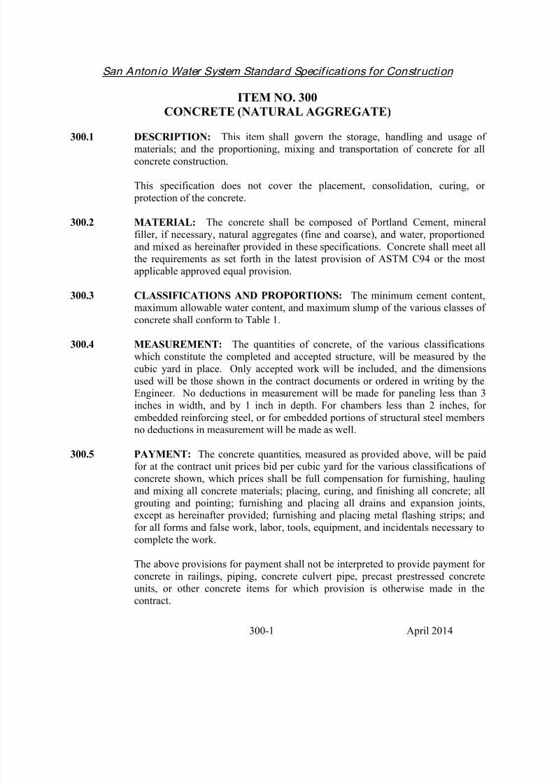
ITEM NO. 300
CONCRETE (NATURAL AGGREGATE)
300.1 DESCRIPTION: This item shall govern the storage, handling and usage ofmaterials; and the proportioning, mixing and transportation of concrete for all
concrete construction.
This specification does not cover the placement, consolidation, curing, or
protection of the concrete.
300.2 MATERIAL: The concrete shall be composed of Portland Cement, mineral
filler, if necessary, natural aggregates (fine and coarse), and water, proportioned
and mixed as hereinafter provided in these specifications. Concrete shall meet allthe requirements as set forth in the latest provision of ASTM C94 or the most
applicable approved equal provision.
300.3 CLASSIFICATIONS AND PROPORTIONS: The minimum cement content,maximum allowable water content, and maximum slump of the various classes of
concrete shall conform to Table 1.
300.4 MEASUREMENT: The quantities of concrete, of the various classifications
which constitute the completed and accepted structure, will be measured by the
cubic yard in place. Only accepted work will be included, and the dimensions
used will be those shown in the contract documents or ordered in writing by theEngineer. No deductions in measurement will be made for paneling less than 3
inches in width, and by 1 inch in depth. For chambers less than 2 inches, forembedded reinforcing steel, or for embedded portions of structural steel membersno deductions in measurement will be made as well.
300.5 PAYMENT: The concrete quantities, measured as provided above, will be paidfor at the contract unit prices bid per cubic yard for the various classifications of
concrete shown, which prices shall be full compensation for furnishing, hauling
and mixing all concrete materials; placing, curing, and finishing all concrete; all
grouting and pointing; furnishing and placing all drains and expansion joints,except as hereinafter provided; furnishing and placing metal flashing strips; and
for all forms and false work, labor, tools, equipment, and incidentals necessary to
complete the work.
The above provisions for payment shall not be interpreted to provide payment for
concrete in railings, piping, concrete culvert pipe, precast prestressed concrete
units, or other concrete items for which provision is otherwise made in thecontract.

8/21/2019 2014 SAWS Construction Specifications
http://slidepdf.com/reader/full/2014-saws-construction-specifications 16/461
San Antonio Water System Standard Specif ications for Construction
300-2 April 2014
The above provisions for payment for drains and expansion joints shall not be
interpreted to provide payment for cast iron or structural steel shapes used in
drains; for structural steel, cast iron or cast steel bearing plates; or for steelmembers used in armoring roadway joints. Payment for these materials shall be
full compensation for work herein specified, including the furnishing of all
materials, equipment, tools, labor, and incidental necessary to complete thework."
No direct measurement or payment will be made for Concrete Class "G," but shall
be considered subsidiary to the particular items required by the contract
documents.
Table 1
Class
Minimum compressive
strength @ 28 days, psi
(Mpa)
Maximum
water/cement
ratio
Slump
range,
inches
Min.-max. sacks
cement, cubic
yard
A 3,000 (20) 7 2-5 5
B 2,500 (17) 8 2-5 4.5
C 2,000 (14) 9 1-4 4
D 1,000 (6) 11 1-4 2
G (as specified in the
contract documents)
5.5 2-3 6.0-8.0
- End of Specification -

8/21/2019 2014 SAWS Construction Specifications
http://slidepdf.com/reader/full/2014-saws-construction-specifications 17/461
San Antonio Water System Standard Specif ications for Construction
301-1 April 2014
ITEM NO. 301
REINFORCING STEEL
301.1 DESCRIPTION: This item shall provide for the furnishing and placing of bar
reinforcing steel for use in structures and other concrete items that requirereinforcing steel as shown in the contract documents..
301.2 MATERIALS: Reinforcing steel shall be grade 60 and all bar reinforcement
shall be deformed, conforming to the latest provision of Item No. 440,
"Reinforcing Steel" of the TX-DOT Standard Specifications or most applicable
approved equal provision. Reinforcing steel bars produced outside of the UnitedStates are acceptable, if such bar reinforcement conforms to the requirements of
the latest provision of the ASTM Specifications for the various designations of
bars.
301.3 BENDING, TOLERANCES AND STORAGE: Bending, tolerances and
storage of reinforcing steel shall conform to the latest provision of Article
440.3.A-C, in Item No. 440, "Reinforcing Steel" of the TX-DOT StandardSpecifications or most applicable approved equal provision.
301.4 SPLICES: No splicing of bars, except when provided in the contract documents,
will be permitted without written approval of the Engineer.
301.5 PLACING REINFORCEMENT: All steel reinforcing shall be accurately
placed in the position shown in the contract documents and firmly held during the placement and setting of concrete. All reinforcement shall be free from dust, rust,
mill scale, paint, oil, mortar or foreign material. Bars shall be tied at all
intersections. Where spacing of bars in each direction is less than 12 inches, only
alternate intersections need be tied. Distances from forms shall be maintained bymeans of stays, precast blocks, ties, hangers, metal chairs or other approved
supports. Blocks for holding reinforcing bars from contact with the forms shall be
precast concrete blocks of approved shape and dimensions or other equallysuitable devices. The use of pebbles, pieces of broken stones or brick, metal pipe
and wooden blocks shall not be permitted. Reinforcement in any sections shall be
placed and then inspected and approved by the Inspector before the placing of
concrete begins.
301.6 MEASUREMENT: The measurement of quantities of bar reinforcing furnished
and placed will be based on the calculated weight of the steel actually placed inaccordance with the contract documents with no allowance made for added bar
lengths or splices, nor for extra steel used when bars larger than those specified

8/21/2019 2014 SAWS Construction Specifications
http://slidepdf.com/reader/full/2014-saws-construction-specifications 18/461
San Antonio Water System Standard Specif ications for Construction
301-2 April 2014
are substituted with the permission of the Engineer. Tie wires and supportingdevices will not be included in the calculated weights. The calculated weight of
bar reinforcement will be determined using the theoretical bar weight set forth in
Table No. 1, with no allowance for overrun or under runs:
301.7 PAYMENT: Reinforcing Steel measured, as provided above, will be paid for at
the contract unit price bid per pound of "Reinforcing Steel," which price shall befull compensation for furnishing, bending, fabricating, welding and placing
reinforcement; for all clips, blocks, metal spacers, ties, wire or other materials
used for fastening reinforcement in place, and for all tools, labor, equipment and
incidentals necessary to complete the work.
Payment for reinforcing an item which specifically includes the cost of
reinforcement shall be paid for as provided in the specifications for those items.
TABLE 1
Bar size,
number
Nominal diameter,
inches
Nominal Area, square
inchesWeight, pound per
linear foot
2 0.250 0.05 0.167
3 0.375 0.11 0.376
4 0.500 0.20 0.668
5 0.625 0.31 1.043
6 0.750 0.44 1.502
7 0.875 0.60 2.044
8 1.000 0.79 2.670
9 1.128 1.00 3.400
10 1.270 1.27 4.303
11 1.410 1.56 5.313
14 1.693 2.25 7.65
18 2.257 4.00 13.60

8/21/2019 2014 SAWS Construction Specifications
http://slidepdf.com/reader/full/2014-saws-construction-specifications 19/461
San Antonio Water System Standard Specif ications for Construction
307-1 April 2014
ITEM NO. 307
CONCRETE STRUCTURES
307.1 DESCRIPTION: This item shall govern the construction of box culverts,headwalls, wingwalls, bridges, box transitions, approach slabs, retaining walls,
inlets, storm sewer structures, sanitary sewer structures and other designatedstructures. All concrete structures shall be constructed in accordance with the
specifications herein outlined and in conformity with the required lines, grades,
sections and details shown in the contract documents or as directed by theEngineer.
307.2 MATERIALS:
1. Concrete: All concrete shall conform to the latest provisions of Item No.
300, "Concrete (Class A)" or the most applicable approved equal provision, or the concrete shall be of a class as noted in the contract
documents.
2. Reinforcing Steel: All reinforcing steel shall conform to the provisions of
Item No. 301, "Reinforcing Steel."
3. Membrane Curing Compound: Provide membrane curing compounds that
conform to the latest provision of TX-DOT’s DMS-4650, “Hydraulic CementConcrete Curing Materials and Evaporation Retardants” or most applicableapproved equal provision.
4. Expansion Joint Materials: Provide materials that conform to the latest
provision of TxDOT’s DMS-6310, “Joint Sealants and Fillers” or mostapplicable approved equal provision.
5. Cast Iron Castings: All cast iron castings shall conform to the latest
provision of the City of San Antonio Department of Public Works'
Standard Specifications for Construction Item No. 409, "Cast IronCastings”, or most applicable approved equal provision.
6. Metal for Structures: Metal for structures shall conform to the latest
provision of the City of San Antonio Department of Public Works'Standard Specifications for Construction Item No. 302, "Metal for
Structures", or most applicable approved equal provision.
307.3 CONSTRUCTION METHODS:
1. Forms: Forms shall be of wood, metal or other approved materials and

8/21/2019 2014 SAWS Construction Specifications
http://slidepdf.com/reader/full/2014-saws-construction-specifications 20/461
San Antonio Water System Standard Specif ications for Construction
307-2 April 2014
shall conform to the following requirements:
a. Wood Forms:
(1) Unexposed concrete surfaces, No. 2 common or better
lumber.
(2) Exposed concrete surfaces, dressed and matched boards of
uniform thickness and width.
b. Plywood: Commercial Standard Douglas Fir, moisture resistant,concrete form plywood, not less than 5 ply and at least 9/16
th of an
inch in thickness. The face of the plywood shall be free from knot
holes and other blemishes.
c. Metal Forms: Metal forms of an approved type that will produce
surfaces equal to or better than those specified for wood forms.
Forms may be constructed of any of the above substances or of other
material if suited to the intended purpose and when approved by the
Inspector. Forms shall be built mortar tight and of sufficient strength to prevent bulging between supports and shall be set and maintained to the
line and grade designated until the concrete is sufficiently hardened to
permit removal. All details of form construction shall be subject to the
approval of the Inspector and, in special cases, the approval of the
Engineer may be required. Permission to place concrete will not be given by the Inspector until all form work has been placed in accordance with
the above requirements. If at any stage of the work, the forms show signsof bulging, sagging or moving, that portion of the concrete causing such
conditions shall be immediately removed, if required by the Inspector, and
the forms reset and securely braced against further movement.
All corners and edges, which will be exposed after construction, shall be
chamfered with triangular chamfer strips ¾ inch measured on the sides.
2. Placing Reinforcement: All steel reinforcement shall be placed in
accordance with Item No. 301, "Reinforcing Steel."
3. Placing Concrete: The base slabs of inlets, junction boxes, headwalls,culverts and other structures shall be placed and allowed to set before the
remainder of the structure is constructed. Suitable provisions shall be
made for bonding the sidewalls to the base slab by means of longitudinal

8/21/2019 2014 SAWS Construction Specifications
http://slidepdf.com/reader/full/2014-saws-construction-specifications 21/461
San Antonio Water System Standard Specif ications for Construction
307-3 April 2014
keys so constructed as to prevent the percolation of water through theconstruction joints. Before concrete is placed in the walls, the keyed-edge
joints shall be thoroughly cleaned of all shavings, sticks, trash or other
extraneous materials. The top slabs of culverts and like structures may be poured monolithic with the walls, provided the walls are poured and
allowed to set a minimum of 1 hour, no more than 2 hours, shall elapse
between the placing of the concrete in the wall and that in the top slab;such interval is to allow for shrinkage of the concrete in the wall. Under
adverse weather conditions, the minimum time will be increased by the
Engineer.
All concrete shall be placed with the aid of mechanical vibrating
equipment supplemented inside the forms. Vibrating equipment shall be
of the internal type and shall maintain a speed of 6,000 impulses per
minute, when submerged in concrete. Vibrators shall be adequate innumber of units to properly consolidate all concrete. Form or surface
vibrators shall not be used. The duration of vibration shall be limited to
properly consolidate the concrete without causing objectionablesegregation of aggregates. Insertion of vibrators into lower courses that
have commenced initial set, or the disturbance or reinforcement in
concrete beginning to set, shall be avoided.
Concrete shall not be allowed to drop freely more than 5 feet in unexposedwork, nor more than 3 feet in exposed work; where greater drops arerequired, a tremie or other approved means shall be employed. Concrete
shall not be placed when the ambient temperature is below 40 F, norwhere the concrete is likely to be subject to freezing before final set has
occurred. When the air temperature is expected to drop below 40 Fduring the first 72 hours of the curing period, polyethylene sheeting or burlap-polyethylene blankets shall be placed in direct contact with the topsurface of the concrete. Concrete may be poured in temperatures below
40 F, when poured in protected areas, or where adequate protection can be provided against freezing, if approved by the Engineer. When concrete
is poured in air temperatures above 85 F, an approved retarding agent,meeting the latest provision of ASTM C494, Type B or most applicableapproved equal provision, will be required in all concrete used insuperstructures and top slabs of culverts unless directed otherwise by the
Engineer.
4. Form Removal: Forms shall be removed only with the approval of theInspector and in a manner to insure complete safety of the structure whenthe structure as a whole is supported on shoring. Form removal fromstructures shall not begin until the concrete has attained the followingcompressive strengths:

8/21/2019 2014 SAWS Construction Specifications
http://slidepdf.com/reader/full/2014-saws-construction-specifications 22/461
San Antonio Water System Standard Specif ications for Construction
307-4 April 2014
a. Vertical forms shall not be removed until the concrete has set aminimum of 24 hours, or the concrete has attained a minimum
compressive strength of 500 psi. b. When wall and top slabs are poured monolithically, wall formsshall not be removed until the concrete has attained a minimumcompressive strength of 2,000 psi.
5. Finish: Honeycomb and other minor defects shall be patched with one partof cement to 2 parts fine aggregate. All exposed surfaces shall be givenone of the following finishes:
a. Rough Finish: Concrete for which no other finish is indicated orspecified shall have fins and rough edges removed.
b. Smooth Finish: Smooth finish shall be given to the interior ofinlets, junction boxes, culverts and other structures. Joint marks,fins and rough edges shall be smoothed off and blemishesremoved, leaving finished surfaces smooth and unmarred, subjectto approval by the Inspector.
c. Floor Finish: Floor finish shall be given to the floors of all inlets,
culverts and other structures, and shall be struck off true to therequired grade as shown in the contract documents and floated to a
smooth, even finish by manual or mechanical methods. No coarse
aggregate shall be visible after finishing.
d. Rubbed Finish: All exposed surfaces of retaining walls, wingwalls,
headwalls and other structures, after patching and painting has
been completed and the surface has been wetted, shall be given afirst rubbing with a No. 16 Carborundum Stone. After the first
rubbing is completed and the ground material has been evenly
spread, the material shall be allowed to take a reset. Aftersufficient aging, the surface shall be wetted and given a finish
rubbing with a No. 30 Carborundum Stone, after which the surface
shall be neatly striped with a brush and allowed to take a reset. Onthe inside surfaces of all culvert walls an area from the top slab, on
a line 30 degrees from the vertical, to the bottom slab shall be
rubbed as specified above.
The entire structure shall be left with a clear, neat, uniform finish,
free from form markings and shall be uniform in color.
e. Sidewalk surfaces shall be given a wood float finish, a light broomfinish, or may be stripped with a brush as directed by the Inspector

8/21/2019 2014 SAWS Construction Specifications
http://slidepdf.com/reader/full/2014-saws-construction-specifications 23/461
San Antonio Water System Standard Specif ications for Construction
307-5 April 2014
or specified in the contract documents.
f. Roadway slabs shall be given a broom finish after completion of
the floating or straight-edging operation, but before thedisappearance of the moisture sheen. The grooves of the finish
shall be parallel to the centerline of the roadway. The average
texture depth of the grooves shall be a minimum of 0.035 inches.
The Contractor has the option of substituting the surface finish described
in the latest provision of the City of San Antonio Department of Public
Works' Standard Specifications for Construction Item No. 311, "ConcreteSurface Finish," or most applicable approved equal provision, on the
surface areas listed in the specification.
6. Curing: Immediately after placing or finishing, concrete surfaces notcovered by forms shall be protected from loss of surface moisture for not
less than 4 curing days. When forms are left in place, they shall be kept
sufficiently wet to reduce cracks in the forms and prevent the form jointsfrom opening. If forms are removed before 4 curing days have transpired,
the formed surface shall be protected for the remainder of the 4 day curing
period. Protection and curing shall be accomplished by one of thefollowing methods and shall be subject to the approval of the Inspector
during the entire curing process:
a. Water Curing: Water curing shall be effected by covering exposed
surfaces with cotton or burlap mats, previously wetted beforeapplying, and kept thoroughly wet during the entire curing period.
The application of the mats shall not mar or disturb surfaces whichwill be exposed on completion.
b. Membrane compound curing: Provide membrane curing compounds
that conform to the latest provision of TxDOT’s DMS-4650, “HydraulicCement Concrete Curing Materials and Evaporation Retardants” or the
most applicable approved equal provision.
7. Fine Grading: All fine grading of structure foundations shall provide for
seating on firm, clean, natural earth foundation except as otherwise provided. Any under-cut foundations, except where authorized, shall be
corrected to the satisfaction of the Inspector, at the sole expense of the
Contractor.
8. Excavation and Backfilling shall conform to the latest provision of the
City of San Antonio Department of Public Works' Standard Specificationsfor Construction Item No. 306, "Structural Excavation" or the most

8/21/2019 2014 SAWS Construction Specifications
http://slidepdf.com/reader/full/2014-saws-construction-specifications 24/461
San Antonio Water System Standard Specif ications for Construction
307-6 April 2014
applicable approved equal provision. All references therein to densityand/or compaction levels are superseded by those of SAWS, described
elsewhere in these standard specifications.
307.4 MEASUREMENT AND PAYMENT: No direct measurement or payment will
be made for the work to be done or the equipment to be furnished under this item,
but shall be considered subsidiary to the particular items of work for which unit prices are required in the proposal.
- End of Specification -

8/21/2019 2014 SAWS Construction Specifications
http://slidepdf.com/reader/full/2014-saws-construction-specifications 25/461
San Antonio Water System Standard Specif ications for Construction
550-1 April 2014
ITEM NO. 550
TRENCH EXCAVATION SAFETY PROTECTION
550.1 DESCRIPTION: This item shall govern the trench excavation safety protectionrequired for the construction of all trench excavation protection systems to be
utilized in the project and including all additional excavation and backfillnecessitated by the protection system.
A trench shall be defined as a narrow excavation made below the surface of the
ground or pavement. In general, the depth is greater than the width, but the width
of a trench is not greater than 15 feet. If forms or other structures are installed or
constructed in an excavation so as to reduce the dimension measured from theforms or structure to the side of the excavation to 15 feet or less (measure at the
bottom of the excavation), the excavation is also considered to be a trench. In
addition, "Trench Excavation Protection" will not be limited to these applications, but may be used whenever deemed expedient and proper to ensuing work.
550.2 CONSTRUCTION: Trench excavation safety protection shall be accomplished
as required by the latest provision of Part 1926, Subpart P - Excavations,Trenching, and Shoring of the Occupational Safety and Health Administration
(OSHA) Standards and Interpretations, or the most applicable approved equal
provision, as may be amended.
550.3 MEASUREMENT: Trench Excavation Safety Protection shall be measured by
the linear foot along the centerline of any OSHA defined trench that may be
entered by personnel and is not greater than 15 feet wide, including manholes andother structures.
550.4 PAYMENT: Payment for Trench Safety Excavation Protection, measured as
prescribed above, shall be made at the unit price bid per linear foot of TrenchExcavation Safety Protection regardless of the depth of the trench.
Payment shall include all components of the Trench Excavation Safety ProtectionSystem which can include, but not be limited to, sloping, sheeting, trench boxes
or trench shields, sheet piling, cribbing, bracing, shoring, dewatering or temporary
diversion and proper recapture and transportation of water to provide adequate
drainage. Payment shall also include the additional excavation and backfillrequired, any jacking, jack removal, and removal of the trench supports after
completion.
Payment of all work prescribed under this item shall be full compensation for all
additional excavation and backfill associated with the item; for any retention by

8/21/2019 2014 SAWS Construction Specifications
http://slidepdf.com/reader/full/2014-saws-construction-specifications 26/461
San Antonio Water System Standard Specif ications for Construction
550-2 April 2014
Contractor of structural design/geotechnical/safety/equipment consultant; forfurnishing, placing and removing all shoring, sheeting, or bracing; for dewatering
or temporary diversion and proper recapture and transportation of water; for all
jacking and jack removal; and for all other labor, material, tools, equipment andincidentals necessary to complete this portion of the work.
- End of Specification -

8/21/2019 2014 SAWS Construction Specifications
http://slidepdf.com/reader/full/2014-saws-construction-specifications 27/461
San Antonio Water System Standard Specif ications for Construction
804-1 April 2014
ITEM NO. 804
EXCAVATION, TRENCHING AND BACKFILL
804.1
DESCRIPTION: This section shall govern the excavation, trenching, and backfilling for water, sanitary sewer, and recycled water construction, unless
otherwise noted in the contract documents. The work shall include all necessarydrainage, dewatering, pumping, bailing, sheeting, shoring and incidental
construction. All existing utilities shall be protected from damage during the
excavation and backfilling of trenches and, if damaged, shall be replaced by theContractor at his expense. Unless otherwise shown in the contract documents, all
excavation shall be unclassified and shall include all materials encountered
regardless of their nature or the manner in which they are removed, to include but
not limited to rock, stone, sand, organic material, or whatever material isencountered. The Contractor shall at all times conform to the latest applicable
provision of subpart “P” entitled “Excavation, Trenching, and Shoring of OSHASafety and Health Regulations for Construction”, or most applicable approved
equal provision. An excavation plan submittal signed and sealed by a Texaslicensed professional engineer shall be submitted for review and acceptance by
the Owner or Engineer, if applicable, one week prior to start of actual
construction activities where the planned excavation is 20 feet or greater.
804.2 SUBMITTALS: Submit any applicable manufacturer’s product data,
instructions, recommendations, and certifications.
804.3 EXCAVATION: The Contractor shall perform all excavation of every
description and of whatever substances, including rock, encountered to the linesand grades shown in the contract documents or determined by the Engineer.During excavation, material suitable for backfilling shall be stockpiled in orderly
manner a sufficient distance from the banks of the trench to avoid overloading
and to prevent slides or cave-ins. All excavated materials not required or suitablefor backfill shall be removed and properly disposed of by the Contractor or as
directed by the Engineer. Grading shall be done as may be necessary to prevent
surface water from flowing into trenches or other excavations, and any water
accumulating therein shall be removed by pumping or by other approvedmethods.
Sheeting and shoring shall be installed in accordance with all applicable safetyrequirements for the protection of the work, adjoining property, and for the safetyof all personnel. Unless otherwise indicated, excavation shall be by open cut,
whether by hand, backhoe, ram-hoe, rock saw, or whatever method as necessary.
Short sections of a trench may be tunneled, if in the opinion of the Engineer, the pipe or structure can be safely and properly installed or constructed, and backfill

8/21/2019 2014 SAWS Construction Specifications
http://slidepdf.com/reader/full/2014-saws-construction-specifications 28/461
San Antonio Water System Standard Specif ications for Construction
804-2 April 2014
can be properly compacted in such tunnel sections.
1. Archaeological (Unidentified Archaeological Sites): If the Contractor
should encounter a section of an archeological feature, such as a acequia(early Spanish irrigation ditch) or any other archaeological deposits during
construction operations, the Contractor must stop excavation immediately
and contact the SAWS Inspector, who will call the City HistoricPreservation Officer at (210) 299-8303 for an archaeological investigation
as per Section 35-432.3 of the City Code, “Unidentified Sites
Archaeological.” The Contractor cannot begin excavation again without
written permission from SAWS. If more than three days are required forinvestigation (not including holidays and weekends) and the Contractor
cannot work on other project scope items, the Contractor will be permitted
to negotiate for additional construction time. The Contractor shall submit
a request in writing within ten days after date of the first notice. If thetime required for investigation does not exceed three days for each event,
contract duration will not be extended.
2. Safety Devices: The Contractor shall provide and maintain barricades,
flags, torches, and other safety devices as required by local, state, and
federal codes and ordinances and conduct work to create a minimuminconvenience to the public. Temporary suspension of work does not
relieve responsibility for the above requirements.
3. Safety and Health Regulations: The Contractor shall at all times conform
to all of the latest applicable regulations of Subpart “P” entitled“Excavation, Trenching, and Shoring of OSHA Safety and Health
Regulations for Construction,” or most applicable approved equal provisions, and all other applicable state and local rules and regulations
804.4 TRENCHING:
1. Trench walls shall be vertical. The practice of undercutting at the bottom
or flaring at the top will not be permitted except where it is justified for
safety or at the Engineer’s and/or Inspector’s direction. In special cases,where trench flaring is required, the trench walls shall remain vertical to a
depth of at least 1 foot above the top of the pipe.
The trench bottom shall be square or slightly curved to the shape of thetrenching machine cutters. The trench shall be accurately graded along its
entire length to provide uniform bearing and support for each section of
pipe installed upon the bedding material. Bell holes and depressions for

8/21/2019 2014 SAWS Construction Specifications
http://slidepdf.com/reader/full/2014-saws-construction-specifications 29/461
San Antonio Water System Standard Specif ications for Construction
804-3 April 2014
joints shall be dug after the trench bottom has been graded and beddinginstalled. The pipe shall rest upon the new bedding material for its full
length.
Where over-excavation occurs and when not as directed by the Engineer
or Inspector, the under-cut trench shall be restored to grade at no cost to
SAWS by replacement with a material conforming to the requirements ofthe bedding material or a material approved by the Engineer.
The depth of cuts indicated on the cut sheets, as furnished by the Engineer,
are from the off-set or cut hub elevation to the invert, or as indicatedotherwise therein.
Minimum Width of Trench: The minimum width of pipe trenches,
measured at the crown of the pipe, shall be not less than 12 inches greaterthan the exterior diameter of the pipe, exclusive of bells. The minimum
base width of such trench shall be not less than 12 inches greater than the
exterior diameter of the pipe, exclusive of special structures orconnections. Such minimum width shall be exclusive of trench supports
and not greater than the width at the top of the trench.
Maximum Width of Trench: The maximum allowable width of trench for
pipelines measured at the top of the pipe shall be the outside diameter of
the pipe (exclusive of bells or collars) plus 24 inches. A trench wider than
the outside diameter plus 24 inches may be used without special bedding if
the Contractor, at his sole expense, furnishes pipe of the required strengthto carry additional trench load. Such modifications shall be submitted to
the Inspector and approved in writing. Whenever such maximumallowable width of trench is exceeded, except as provided for in the
contract documents, or by written approval of the Engineer, the
Contractor, at his sole expense, shall encase the pipe in concrete from
trench wall to trench wall, or with other approved pipe bedding material.Any excavation wider than this maximum width or subsequent surface or
paving work, will be done at the Contractor’s sole expense.
The depth of cut as indicated on the cut sheet for pay purposes may be
more or less than the actual excavated depth. The variation is based on thesurface elevation prior to the Contractor’s operation and the invert of the
sewer line.
2. When unsuitable bearing materials such as water, silt, muck, trash, debris
or rock in ledge, boulder or coarse gravel (particle size larger than 1- ¾

8/21/2019 2014 SAWS Construction Specifications
http://slidepdf.com/reader/full/2014-saws-construction-specifications 30/461
San Antonio Water System Standard Specif ications for Construction
804-4 April 2014
inch) is encountered at the bearing level, the Contractor shall over-excavate and remove such materials to a depth no less than 6 inches below
the bottom of the pipe and replace it with a material conforming to the
requirements of Paragraph 804.5.2.a, 804.6, or as approved by theEngineer and/or Inspector.
3. Dewatering: Prevent surface water and subsurface or groundwater fromflowing into excavations and from flooding project site and surrounding
area.
a. The Contractor shall not allow water to accumulate in excavationsor at subgrade level. Remove water to prevent softening of
foundation bottoms and soil changes detrimental to stability of
subgrades and foundations. Provide and maintain dewatering
system components necessary to convey water from excavations.
b. Convey water removed from excavation and rainwater to
collecting or runoff areas away from buildings and other structures.Establish and maintain temporary drainage ditches and other
diversions outside excavation limits. Do not use trench
excavations as temporary drainage ditches.
c. Dewatering devices shall be provided by the Contractor with filters
to prevent the removal of fines from the soil. Should the pumping
system draw fines from the soil, the Inspector shall order
immediate shutdown, and remedial measures will be theresponsibility of the Contractor.
d. Upon completion of the dewatering work, the Contractor shall
remove all equipment and leave the construction area in a neat,
clean, condition that is acceptable to the Inspector
e. The Contractor shall maintain groundwater table at least 12 inches
below the finished excavation subgrade.
f. Dewatering Performances. Performances of the dewatering
system for lowering groundwater shall be measured by observationwells on piezometers installed in conjunction with the dewatering
system, and these shall be documented at least daily. TheContractor shall maintain a log of these readings and submit them
to the Inspector.

8/21/2019 2014 SAWS Construction Specifications
http://slidepdf.com/reader/full/2014-saws-construction-specifications 31/461
San Antonio Water System Standard Specif ications for Construction
804-5 April 2014
No direct payment shall be made for costs associated withdewatering. All costs in connection therewith shall be included in
the applicable contract price for the item to which the work
pertains.
804.5 BACKFILLING SANITARY SEWER TRENCHES:
1. General: Trenches shall not be backfilled until the construction structures
or appurtenances, as installed, conform to the requirements specified.
Where specified, only the secondary backfilling may incorporate
excavated materials approved for backfilling, consisting of earth, loam,sandy clay, sand and gravel, soft shale or other approved materials, free
from large clods of earth or stones. Where pipe is specially coated or
sleeve/tape wrapped for protection against corrosion, care shall be taken
not to damage the coating or sleeve/tape wrap.
Where a trench has been improperly backfilled, or where settlement
occurs, the identified section shall be excavated to a depth and length 50feet beyond the failed area, then refilled and compacted to the grade and
compaction level required. The use of sand backfill shall not be allowed.
All compaction within the secondary backfill zone shall be such that theapparent dry density of each layer shall be not less than 98% from the top
of the initial backfill to the bottom of pavement section. The pavement
(asphalt) section shall have 95% compaction density with a maximum dry
density at + or – 2% optimum moisture content as determined by tests on
samples as outlined in the latest provisions of TX-DoT Testing MethodTex 113-E or most applicable approved equal provisions, unless otherwise
shown on the contract documents. At the time of compaction, the watercontent shall be at optimum moisture content, + or - 2% points.
See Table 1 at the end of this specification for an outline of the bedding
and initial backfill requirements for various pipe types.
2. Sanitary Sewer Backfilling: Backfilling for sanitary sewers is divided
into three (3 separate zones: (a) bedding: the material in the trench bottomin direct contact with the bottom of the pipe; (b) initial backfill: the
backfill zone extending from the surface of the bedding to a point 1 footabove the top of the pipe; and (c) secondary backfill: the backfill zone
extending from the initial backfill surface to the top of the trench.Materials and placement for each of the zones shall be as described herein.
a. Bedding:

8/21/2019 2014 SAWS Construction Specifications
http://slidepdf.com/reader/full/2014-saws-construction-specifications 32/461
San Antonio Water System Standard Specif ications for Construction
804-6 April 2014
(1) Stable Material: Existing stable material present during
excavation includes:
Trench bottom (free of water, muck, debris);
Rock in boulder, ledge or coarse gravel (particle size notlarger than 1- ¾ inch) formations;
Coarse sand and gravels with maximum particle size of 1-
¾ inch, various graded sands and gravels containing small percentages of fines, generally granular and non-cohesive
either wet or dry; and
Fine sands and clayey gravels; fine sand, sand-claymixtures, clay and gravel-clay mixtures.
(2) Unstable Material: Existing unstable materials are silt,muck, trash or debris in the trench bottom bearing level;
rock on boulder ledge or coarse gravel (particle size larger
than 1- ¾ inch) formations.
(3) Bedding Material: The existing material at the bearing level
shall be removed and replaced to a minimum depth of 6
inches or 1/8 of the outside diameter of the pipe, whichever
is greater, with bedding material. The bedding materialshall extend up the sides of the pipe sufficient to embed the
lower quadrant of the pipe. The bedding material shall becomposed of well-graded, crushed stone or gravel
conforming to the following requirements unless modified
by the Engineer in writing.
Sewer Gravel Percent
Passing 1- ½ inch sieve 100Passing 1 inch sieve 95 to 100
Passing 1/2” inch sieve 25 to 60Passing No. 4 sieve 0 to 10
Passing No. 8 sieve 0 to 5
(4) Over Excavation: Where the trench bottom has been over

8/21/2019 2014 SAWS Construction Specifications
http://slidepdf.com/reader/full/2014-saws-construction-specifications 33/461
San Antonio Water System Standard Specif ications for Construction
804-7 April 2014
excavated beyond the limits as defined in Item No. 848,“Sanitary Sewers,” due to removal of unstable material, the
pipe shall be concrete-encased. Encasement shall extend
from the trench wall to trench wall and be a minimum of 6inches above the top of pipe. No separate pay item (See
Item No. 858).
(5) Reduced Excavation: Where the trench bottom is not
excavated in accordance with the specification due to rock
or other hard under lying materials, then the pipe shall be
concrete encased as defined in Item No. 858, “ConcreteEncasement.”
(6) Consolidating Backfill Material: The Initial Bedding
material shall be consolidated to assure it is incorporatedfrom the bottom of the trench up to the pipe centerline. A
hand-held vibrator, commonly used for concrete work, can
be used for this purpose. The vibrator shall be insertedevery 3 feet on each side of the pipe.
b. Initial Backfill: Initial backfill is defined as backfill having athickness in its compacted state from the surface of the bedding to
a point 1 foot above the top of the pipe.
Initial backfill shall consist of gravel which conforms to the
requirements of Item No. 804.5.2. a (3).
For sewer lines up to 24 inches in diameter initial backfill materialshall be placed in two separate lifts above the bedding material the
pipe is set on. The first lift shall be spread uniformly and
simultaneously on each side and under the bottom quadrant of the
pipe to the mid-point or spring line of the pipe.
Consolidate the Initial Backfill material as per section 804.5.2.(6).
Placement of the first lift of initial backfill shall be subject to
inspection and approval prior to placement of second lift, whichshall extend from the spring line of the pipe to a minimum of 1
foot above the top of the pipe. The second lift shall be evenlyspread in a similar manner as the first lift.
For diameters larger than 24 inches, initial backfill material shall
8/21/2019 2014 SAWS Construction Specifications
http://slidepdf.com/reader/full/2014-saws-construction-specifications 34/461
San Antonio Water System Standard Specif ications for Construction
804-8 April 2014
be evenly and simultaneously spread alongside, under the lowerquadrant the pipe and over the pipe in 12 inch lifts to a point
sufficient to a minimum of 1 foot above the top of the pipe.
Consolidate the Initial Backfill material as per section 804.5.2.(6).
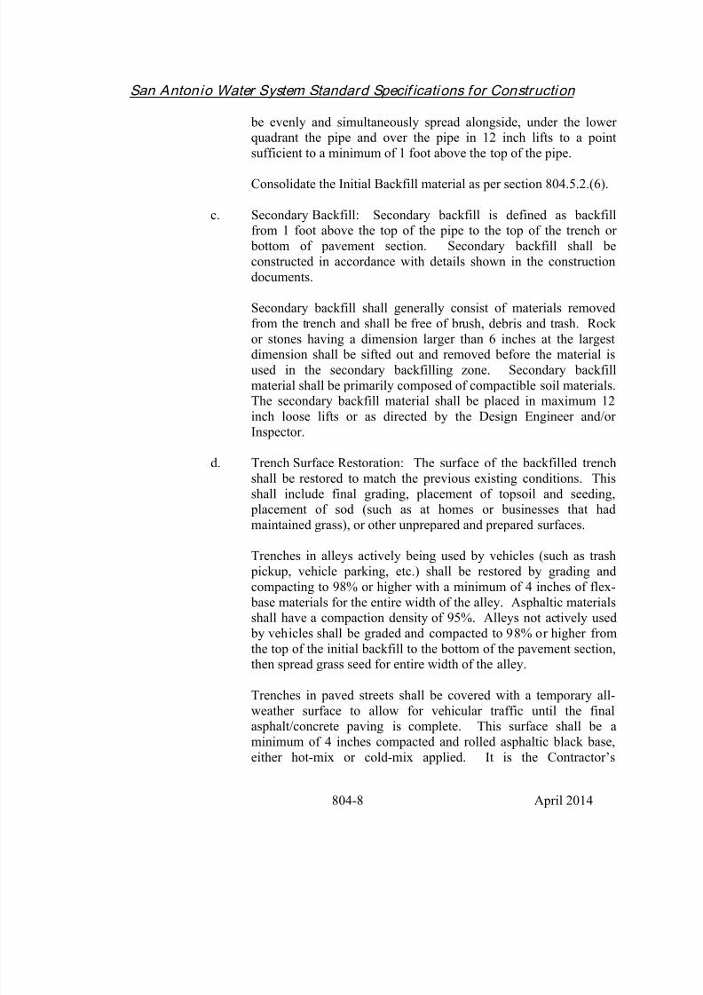
c. Secondary Backfill: Secondary backfill is defined as backfillfrom 1 foot above the top of the pipe to the top of the trench or
bottom of pavement section. Secondary backfill shall be
constructed in accordance with details shown in the construction
documents.
Secondary backfill shall generally consist of materials removed
from the trench and shall be free of brush, debris and trash. Rock
or stones having a dimension larger than 6 inches at the largestdimension shall be sifted out and removed before the material is
used in the secondary backfilling zone. Secondary backfill
material shall be primarily composed of compactible soil materials.The secondary backfill material shall be placed in maximum 12
inch loose lifts or as directed by the Design Engineer and/or
Inspector.
d. Trench Surface Restoration: The surface of the backfilled trench
shall be restored to match the previous existing conditions. This
shall include final grading, placement of topsoil and seeding,
placement of sod (such as at homes or businesses that hadmaintained grass), or other unprepared and prepared surfaces.
Trenches in alleys actively being used by vehicles (such as trash
pickup, vehicle parking, etc.) shall be restored by grading and
compacting to 98% or higher with a minimum of 4 inches of flex-
base materials for the entire width of the alley. Asphaltic materialsshall have a compaction density of 95%. Alleys not actively used
by vehicles shall be graded and compacted to 98% or higher from
the top of the initial backfill to the bottom of the pavement section,then spread grass seed for entire width of the alley.
Trenches in paved streets shall be covered with a temporary all-
weather surface to allow for vehicular traffic until the finalasphalt/concrete paving is complete. This surface shall be a
minimum of 4 inches compacted and rolled asphaltic black base,
either hot-mix or cold-mix applied. It is the Contractor’s
8/21/2019 2014 SAWS Construction Specifications
http://slidepdf.com/reader/full/2014-saws-construction-specifications 35/461
San Antonio Water System Standard Specif ications for Construction
804-9 April 2014
responsibility to maintain this surface until the final streetrestoration is complete. Temporary street striping may also be
required. This surface must be removed prior to final asphalting.
All street work shall be done in accordance with the latest City ofSan Antonio Public Works’ (or other city as applicable)
construction specifications.
Included in this requirement is replacement of any curbs or
sidewalks damaged or removed during the construction.
No separate payment for the surface restoration is permitted. Thecost for this work must be included in the appropriate bid item.
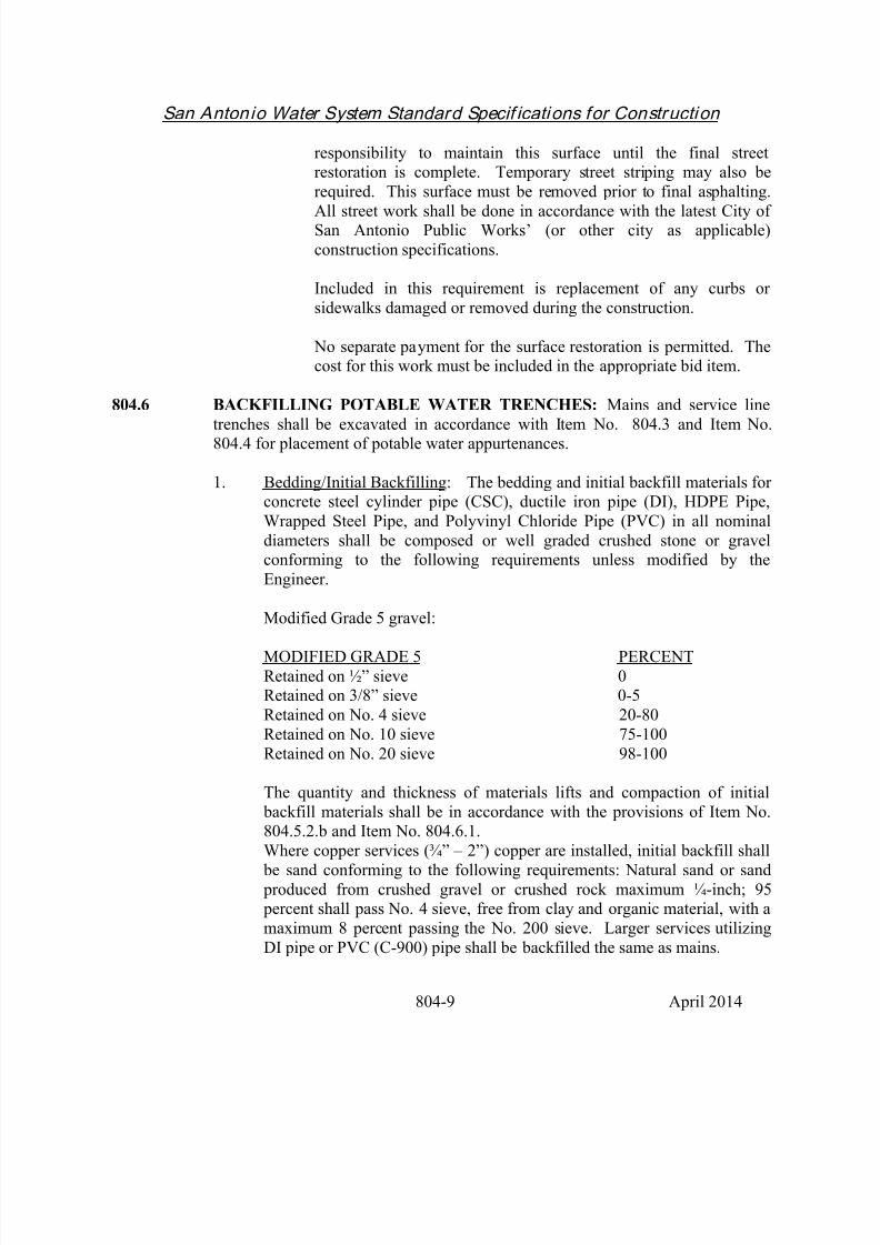
804.6 BACKFILLING POTABLE WATER TRENCHES: Mains and service line
trenches shall be excavated in accordance with Item No. 804.3 and Item No.804.4 for placement of potable water appurtenances.
1. Bedding/Initial Backfilling: The bedding and initial backfill materials forconcrete steel cylinder pipe (CSC), ductile iron pipe (DI), HDPE Pipe,
Wrapped Steel Pipe, and Polyvinyl Chloride Pipe (PVC) in all nominal
diameters shall be composed or well graded crushed stone or gravelconforming to the following requirements unless modified by the
Engineer.
Modified Grade 5 gravel:
MODIFIED GRADE 5 PERCENT
Retained on ½” sieve 0Retained on 3/8” sieve 0-5
Retained on No. 4 sieve 20-80
Retained on No. 10 sieve 75-100
Retained on No. 20 sieve 98-100
The quantity and thickness of materials lifts and compaction of initial
backfill materials shall be in accordance with the provisions of Item No.804.5.2.b and Item No. 804.6.1.
Where copper services (¾” – 2”) copper are installed, initial backfill shall be sand conforming to the following requirements: Natural sand or sand
produced from crushed gravel or crushed rock maximum ¼-inch; 95 percent shall pass No. 4 sieve, free from clay and organic material, with a
maximum 8 percent passing the No. 200 sieve. Larger services utilizing
DI pipe or PVC (C-900) pipe shall be backfilled the same as mains.

8/21/2019 2014 SAWS Construction Specifications
http://slidepdf.com/reader/full/2014-saws-construction-specifications 36/461
San Antonio Water System Standard Specif ications for Construction
804-10 April 2014
2. Secondary Backfill: Secondary backfill materials for all types and sizes
of pipe shall be as defined in Item No. 804.5.2. (c), “Secondary Backfill.”
Secondary backfill materials shall be placed and compacted in accordancewith the provisions of Item No. 804.5.2. (c), “Secondary Backfill.”
3. Trench Surface Restoration: Trench surface restoration shall beaccomplished as defined in Item No. 804.5.2. (d).
804.7 DISPOSAL OF EXCAVATED MATERIALS: Any excess excavated
material, not utilized after all fill requirements have been met, shall become theresponsibility of the Contractor. The Contractor shall dispose of it by hauling and
wasting outside the limits of the rights-of-way or easements of this project and of
public thoroughfares and water courses, in conformity with pertinent City,
County, State and Federal codes and ordinances and in a manner meeting theapproval of the Engineer.
804.8 QUALITY CONTROL:
1. The Contractor shall procure, store, and place materials from either onsite
or offsite sources which comply with the specified requirements.
2. Quality Assurance Testing: The Owner shall have such tests and
inspections as he may desire performed by a nationally-accredited,
independent testing laboratory for his guidance and control of the work.
Payment for such tests shall be the responsibility of the Owner, includingthe material proctor tests and density tests. The Contractor shall request
testing work performed by the Owner by notifying the Owner of the areas
available by Station Numbers or Dimensions and Lift Numbers. TheContractor shall provide access to the test area, associated trench
excavation safety protection, and backfilling of the test areas. The
frequency and location of testing shall be determined solely by the Owner.The Owner may test any lift of fill at any time, location, or elevation.
3. Quality Control Testing: The Contractor shall be responsible for
compaction in accordance with the appropriate Specification. Compaction
tests will be done at one location point randomly selected or as indicated by the SAWS Inspector/Test Administrator, per each 12 inch loose lift per
400 linear feet. The inspector shall determine the depth at which the
density test shall be taken. All depths shall be considered for testingwithout a predetermined maximum or minimum.
8/21/2019 2014 SAWS Construction Specifications
http://slidepdf.com/reader/full/2014-saws-construction-specifications 37/461
San Antonio Water System Standard Specif ications for Construction
804-11 April 2014
Note : Tests requirements above are indicated as a minimum requirement,but maybe subjected to follow more stringent requirements as established
by other appropriate agencies (such as City of San Antonio Public Works
Right-of-Way Management Plan, etc.).
Note : Any failed test shall require the Contractor to remove and replace
that layer of backfill to 50 feet from either side from the failed testlocation. The Contractor will also be required at no cost to SAWS to
provide two additional tests at the replaced location where the initial test
failed and at one location point, randomly selected or as indicated by the
SAWS Inspector/Test Administrator.
Note: Sanitary Sewer Laterals will be subject to compaction tests at the
discretion of the SAWS Inspector/Test Administrator within 400 linear foot
segments. Any failed test shall require the Contractor to remove andreplace failed backfill. The Contractor will also be required at no
additional cost to SAWS to provide one test at the replaced location where
the initial tests failed.
The Contractor shall be responsible for all costs associated with the
proctor and density tests, and for providing to SAWS and Consultant, ifapplicable, verification that necessary compaction levels were achieved.
These tests shall be performed by a nationally-accredited, independent
testing laboratory. .
The Contractor shall provide access to the test area, associated trenchexcavation safety protection, and backfilling of the test areas at the
Contractor’s expense.
The Owner will determine in-place density and moisture content by any
one or combination of the following methods: The latest provisions of
ASTM D2922 (density of soil and soil aggregate in-place by nuclearmethods – shallow depth), D1556 (density and unit weight of soil in-place
by sand cone method), D2216 (lab density of water content of soil and
rock), D3017 (water content of soil and rock – shallow depth in-place by
nuclear methods) or most applicable approved equal provisions.
804.9 MEASUREMENT: Excavation, Trenching and Backfill will not be measured
for payment.
804.10 PAYMENT: No direct payment shall be made for incidental costs associated
with quality control testing, excavation, trenching and backfilling for water mains

8/21/2019 2014 SAWS Construction Specifications
http://slidepdf.com/reader/full/2014-saws-construction-specifications 38/461
San Antonio Water System Standard Specif ications for Construction
804-12 April 2014
and sanitary sewers, and all costs in connection therewith shall be included in theapplicable contract price for the item to which the work pertains.
TABLE 1
BEDDING AND INITIAL BACKFILL REQUIREMENTS
UNSTABLE STABLE* ROCK
Bedding Initial
Backfill
Bedding Initial
Backfill
Bedding Initial
Backfill
WATER 6" or D/8 1.0' above
pipe
6" or D/8 1.0' above pipe 6" or D/8 1.0' above pip
CSC Modified
Grade 5
Modified
Grade 5
Modified
Grade 5
Modified
Grade 5
Modified
Grade 5
Modified
Grade 5
DI Modified
Grade 5
Modified
Grade 5
Modified
Grade 5
Modified
Grade 5
Modified
Grade 5
Modified
Grade 5
PVC Modified
Grade 5
Modified
Grade 5
Modified
Grade 5
Modified
Grade 5
Modified
Grade 5
Modified
Grade 5
HDPE Modified
Grade 5
Modified
Grade 5
Modified
Grade 5
Modified
Grade 5
Modified
Grade 5
Modified
Grade 5
WSP ModifiedGrade 5
ModifiedGrade 5
ModifiedGrade 5
ModifiedGrade 5
ModifiedGrade 5
ModifiedGrade 5
SEWER 6" 1.0' above pipe 6" 1.0' above pipe 6" 1.0' above pip
RIGID sewer gravel sewer gravel sewer
gravel
sewer gravel sewer gravel sewer gravel
FLEXIBLE sewer gravel sewer gravel sewer sewer gravel sewer gravel sewer gravel

8/21/2019 2014 SAWS Construction Specifications
http://slidepdf.com/reader/full/2014-saws-construction-specifications 39/461
San Antonio Water System Standard Specif ications for Construction
804-13 April 2014
gravel
* When the native material encountered is clean sand, this material may be utilized for beddingand initial backfill at the Engineer's direction.
HDPE = High Density Polyethylene Pipe. WSP = Tape Wrapped Steel Pipe.
D = Outside Diameter of Pipe.Modified Grade 5 --- rounded rock
--- See Item No. 804.6.1 for gradation
Sewer Gravel --- See Item No. 804.5.2. a (3)

8/21/2019 2014 SAWS Construction Specifications
http://slidepdf.com/reader/full/2014-saws-construction-specifications 40/461

8/21/2019 2014 SAWS Construction Specifications
http://slidepdf.com/reader/full/2014-saws-construction-specifications 41/461

8/21/2019 2014 SAWS Construction Specifications
http://slidepdf.com/reader/full/2014-saws-construction-specifications 42/461
San Antonio Water System Standard Specif ications for Construction
808-1 April 2014
ITEM NO. 808 REINFORCED CONCRETE VAULTS
808.1 DESCRIPTION: Reinforced concrete vaults shall be cast-in-place and shall
include reinforcing steel, forms, finishing, curing, and all other appurtenant workrequired to provide a complete and functional structure.
All cast-in-place concrete shall be accurately formed and properly placed andfinished as shown in the contract documents.
The Contractor shall inform the Engineer at least 24 hours in advance, of time and
location at which he/she intends to place concrete in order for inspection of forms,reinforcing steel placement, and other preparatory work.
Precast vaults conforming to the Standard Drawings and Specifications shall be
acceptable as a substitute to the cast-in-place vaults or as approved by theEngineer.
808.2 MATERIALS: Concrete used shall be transit mix and shall have a 28 daycompressive strength of 3,000 psi with a maximum slump of 6 inches and a
minimum slump of 3 inches. The use of admixtures shall not be permitted unless
approved by the Engineer. Cement shall be Type I or Type III and shall conform
to the general requirements contained in the Materials Specifications Item 100-10and the latest provision of ASTM Specifications C150 and C156 or most
applicable approved equal provision.
808.3 CONSTRUCTION:
1. Forms: Forms shall be designed to produce hardened concrete having theshape, lines, and dimensions shown in the contract documents.
Surfaces which will be exposed to view when construction is completed
shall be prefabricated plywood panel forms, job-built plywood forms, orforms that are lined with plywood or fiberboard. The forms shall produce
finished surfaces that are free from off-sets, ridges, waves, and concave or
convex areas.
Plywood or lined forms will not be required for surfaces which are
normally submerged or not ordinarily exposed to view. Other types of
forms, such as steel or unlined wooden forms, may be used for surfaceswhich are not restricted to plywood or lined forms and may be used as

8/21/2019 2014 SAWS Construction Specifications
http://slidepdf.com/reader/full/2014-saws-construction-specifications 43/461
San Antonio Water System Standard Specif ications for Construction
808-2 April 2014
backing for form linings.
Before concrete is placed, a film of light form oil shall be applied to the
forms.
Forms shall be substantial and sufficiently tight to prevent leakage of
mortar. Forms shall be thoroughly cleaned, braced, or tied to maintain thedesired position, shape, and alignment during and after concrete
placement.
Form ties shall be corrosion resistant and shall have sufficient strength andrigidity to support and maintain the form in proper position and alignment.
2. Form Removal: Forms shall be removed after 24 hours, provided that the
exposed surfaces can be immediately and effectively sealed to prevent lossof moisture. Otherwise, the forms shall remain in place for 48 hours.
Precautions shall be taken in form removal to avoid surface gouging,
corner or edge breaking, and other damage to the concrete.
3. Reinforcing Steel: Reinforcing steel shall be accurately formed and shall
be free from loose rust, scale, and contaminants which reduce bond.Unless otherwise shown in the contract documents, bar reinforcement
shall be deformed and conform to the general requirements contained in
Item No. 301, "Reinforcing Steel.".
4. Reinforcing Steel Placement: Reinforcing steel shall be accurately positioned on supports, spaces, hangers, or other reinforcements and shall
be secured in place with wire ties or suitable clips. All bars shall be shopfabricated and bent cold.
5. Concrete Placement: Concrete shall be placed as nearly as practicable in
its final position to avoid segregation due to rehandling. When theconcrete pour has commenced, it shall be carried on as a continuous
operation until the placing of the panel or section is completed as a whole.
All concrete shall be thoroughly compacted by suitable means during pouring operations and shall be thoroughly worked around reinforcement
bars and into the corners of the forms. Mechanical vibration or otheracceptable means shall be used to completely embed the reinforcement
and eliminate honeycomb. Finished surfaces shall be brought to propergrade, struck off, and completed in a workmanlike manner. No
honeycombing, rough spots or protruding stones shall be left exposed.

8/21/2019 2014 SAWS Construction Specifications
http://slidepdf.com/reader/full/2014-saws-construction-specifications 44/461
San Antonio Water System Standard Specif ications for Construction
808-3 April 2014
6. Curing: Concrete shall be protected from loss of moisture for at least 7days after placement. Curing of concrete shall be by methods which will
keep the concrete surfaces adequately wet during the specified curing
period.
a. Water Curing: Water saturation of concrete surfaces shall begin as
quickly as possible after the initial set of the concrete. The rate ofwater application shall be regulated to provide complete surface
coverage with a minimum of runoff.
b. Membrane Curing: Chlorinated, rubber-type, membrane curingcompound may be used in lieu of water curing on concrete which
will not be covered later with mortar or additional concrete.
Membrane curing compound shall be spray applied at coverage ofnot more than 300 square feet per gallon. If forms are removed
before the end of the specified curing period, curing compound
shall be immediately applied to the formed surfaces before theydry out.
Curing compound shall be suitably protected against abrasionduring the curing period.
7. Finishing Surfaces: Fins and other surface projections shall be removed
from all formed surfaces. All exposed exterior surfaces shall have a
rubbed finish. The floor surface shall be brush finished, unless otherwisespecified.
8. Repairing Defective Concrete: Defects in formed concrete surfaces shall
be repaired to the satisfaction of the Engineer within 24 hours, and
defective concrete shall be replaced within 48 hours after the forms have
been removed. All concrete which is honeycombed or otherwise defectiveshall be cut out and removed to sound concrete with edges square cut to
avoid feathering.
Concrete repair work shall be performed in a manner that will not interfere
with thorough curing of surrounding concrete. Repair work shall beadequately cured.
9. Painting: All exposed metallic surfaces such as the cover plate, hinges,
handles, and other exposed hardware, shall be primed and painted with
one coat of primer and one coat of aluminum paint of approved and

8/21/2019 2014 SAWS Construction Specifications
http://slidepdf.com/reader/full/2014-saws-construction-specifications 45/461
San Antonio Water System Standard Specif ications for Construction
808-4 April 2014
compatible quality.
10. Backfill: The Contractor shall cover the openings at each end of the vault
with ¼ inch plywood placed outside the vault. Selected backfill(consisting of job excavated materials, finely divided and free from debris,
organic material and stones larger than two inches in greatest dimension)
shall be placed in uniform layers not exceeding eight inches in un-compacted thickness and shall be carefully compacted around the sides of
the vault until level with the surrounding ground.
808.4 MEASUREMENT: Reinforced concrete vaults shall be measured by the unit ofthe various sizes.
808.5 PAYMENT: Payment for reinforced concrete vaults will be made at the unit
price for each size vault installed.
- End of Specification -
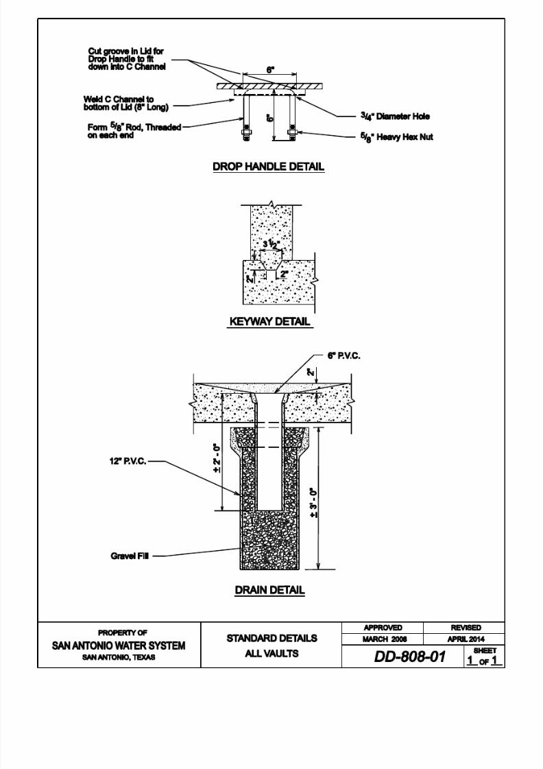
8/21/2019 2014 SAWS Construction Specifications
http://slidepdf.com/reader/full/2014-saws-construction-specifications 46/461

8/21/2019 2014 SAWS Construction Specifications
http://slidepdf.com/reader/full/2014-saws-construction-specifications 47/461

8/21/2019 2014 SAWS Construction Specifications
http://slidepdf.com/reader/full/2014-saws-construction-specifications 48/461

8/21/2019 2014 SAWS Construction Specifications
http://slidepdf.com/reader/full/2014-saws-construction-specifications 49/461

8/21/2019 2014 SAWS Construction Specifications
http://slidepdf.com/reader/full/2014-saws-construction-specifications 50/461

8/21/2019 2014 SAWS Construction Specifications
http://slidepdf.com/reader/full/2014-saws-construction-specifications 51/461

8/21/2019 2014 SAWS Construction Specifications
http://slidepdf.com/reader/full/2014-saws-construction-specifications 52/461

8/21/2019 2014 SAWS Construction Specifications
http://slidepdf.com/reader/full/2014-saws-construction-specifications 53/461

8/21/2019 2014 SAWS Construction Specifications
http://slidepdf.com/reader/full/2014-saws-construction-specifications 54/461

8/21/2019 2014 SAWS Construction Specifications
http://slidepdf.com/reader/full/2014-saws-construction-specifications 55/461

8/21/2019 2014 SAWS Construction Specifications
http://slidepdf.com/reader/full/2014-saws-construction-specifications 56/461
8/21/2019 2014 SAWS Construction Specifications
http://slidepdf.com/reader/full/2014-saws-construction-specifications 57/461
San Antonio Water System Standard Specif ications for Construction
809-1 April 2014
ITEM NO. 809 REINFORCED CONCRETE VAULTS FOR METERED FIRELINE
SERVICES
809.1 DESCRIPTION: Reinforced concrete vaults shall be precast with reinforcing
steel and include all other appurtenant work required to provide a complete andfunctional structure.
All precast concrete vaults shall be accurately formed and finished as shown in
the contract documents.
Precast vaults conforming to the Standard Drawings and Specifications shall be
acceptable as a substitute to the cast-in-place vaults or as approved by the
Engineer. Contractor will give 24 hour notification to the Inspector assigned tothe project before setting a metered fire line vault.
809.2 MATERIALS: Concrete used shall be transit mix and shall have a 28 daycompressive strength of 3,000 psi with a maximum slump of 6 inches and a
minimum slump of 3 inches. The use of admixtures shall not be permitted unless
approved by the Engineer. Cement shall be Type I or Type III and shall conform
to the general requirements contained in the Materials Specifications Item 100-10and the latest provision of ASTM Specifications C150 and C156 or most
applicable approved equal provision.
809.3 CONSTRUCTION:
1. Forms: Forms shall be designed to produce hardened concrete having the
shape, lines, and dimensions shown in the contract documents.
Surfaces which will be exposed to view when construction is completed
shall be prefabricated plywood panel forms, job-built plywood forms, orforms that are lined with plywood or fiberboard. The forms shall produce
finished surfaces that are free from off-sets, ridges, waves, and concave or
convex areas.
Plywood or lined forms will not be required for surfaces which arenormally submerged or not ordinarily exposed to view. Other types of
forms, such as steel or unlined wooden forms, may be used for surfaceswhich are not restricted to plywood or lined forms and may be used as
backing for form linings.

8/21/2019 2014 SAWS Construction Specifications
http://slidepdf.com/reader/full/2014-saws-construction-specifications 58/461
San Antonio Water System Standard Specif ications for Construction
809-2 April 2014
Before concrete is placed, a film of light form oil shall be applied to the
forms.
Forms shall be substantial and sufficiently tight to prevent leakage ofmortar. Forms shall be thoroughly cleaned, braced, or tied to maintain the
desired position, shape, and alignment during and after concrete placement.
Form ties shall be corrosion resistant and shall have sufficient strength and
rigidity to support and maintain the form in proper position and alignment.
2. Form Removal: Forms shall be removed after 24 hours provided that the
exposed surfaces can be immediately and effectively sealed to prevent loss
of moisture. Otherwise, the forms shall remain in place for 48 hours.
Precautions shall be taken in form removal to avoid surface gouging,corner or edge breaking, and other damage to the concrete.
3. Reinforcing Steel: Reinforcing steel shall be accurately formed and shall
be free from loose rust, scale, and contaminants which reduce bond.
Unless otherwise shown on the drawings or specified herein, barreinforcement shall be deformed and conform to the general requirements
contained in Item No. 301, "Reinforcing Steel."
4. Reinforcing Steel Placement: Reinforcing steel shall be accurately positioned on supports, spaces, hangers, or other reinforcements and shall
be secured in place with wire ties or suitable clips. All bars shall be shopfabricated and bent cold.
5. Concrete Placement: Concrete shall be placed as nearly as practical in its
final position to avoid segregation due to rehandling. When the concrete
pour has commenced, it shall be carried on as a continuous operation untilthe placing of the panel or section is completed as a whole. All concrete
shall be thoroughly compacted by suitable means during pouring
operations and shall be thoroughly worked around reinforcement bars andinto the corners of the forms. Mechanical vibration or other acceptable
means shall be used to completely embed the reinforcement and eliminate
honeycomb. Finished surfaces shall be brought to proper grade, struck
off, and completed in a workmanlike manner. No honeycombing, roughspots or protruding stones shall be left exposed.
6. Curing: Concrete shall be protected from loss of moisture for at least 7days after placement. Curing of concrete shall be by methods which will
keep the concrete surfaces adequately wet during the specified curing

8/21/2019 2014 SAWS Construction Specifications
http://slidepdf.com/reader/full/2014-saws-construction-specifications 59/461
San Antonio Water System Standard Specif ications for Construction
809-3 April 2014
period.
a. Water Curing: Water saturation of concrete surfaces shall begin as
quickly as possible after the initial set of the concrete. The rate ofwater application shall be regulated to provide complete surface
coverage with a minimum of runoff.
b. Membrane Curing: Chlorinated, rubber-type, membrane curing
compound may be used in lieu of water curing on concrete which
will not be covered later with mortar or additional concrete.
Membrane curing compound shall be spray applied at coverage of
not more than 300 square feet per gallon. If forms are removed
before the end of the specified curing period, curing compound
shall be immediately applied to the formed surfaces before theydry out.
Curing compound shall be suitably protected against abrasion
during the curing period.
7. Finishing Surfaces: Fins and other surface projections shall be removed
from all formed surfaces. All exposed exterior surfaces shall have a
rubbed finish. The floor surface shall be brush finished, unless otherwise
specified.
8. Repairing Defective Concrete: Defects in formed concrete surfaces shall be repaired to the satisfaction of the Engineer within 24 hours, anddefective concrete shall be replaced within 48 hours after the forms have
been removed. All concrete which is honeycombed or otherwise defective
shall be cut out and removed to sound concrete with edges square cut to
avoid feathering.
Concrete repair work shall be performed in a manner that will not interfere
with thorough curing of surrounding concrete. Repair work shall beadequately cured.
9. Painting: All exposed metallic surfaces such as the cover plates, hinges,
handles, and other exposed hardware shall be primed and painted with onecoat of primer and one coat of aluminum paint of approved and
compatible quality.
10. Backfill: The Contractor shall cover the openings at each end of the vault
with grout placed around the pipe penetration inside and outside of the

8/21/2019 2014 SAWS Construction Specifications
http://slidepdf.com/reader/full/2014-saws-construction-specifications 60/461
San Antonio Water System Standard Specif ications for Construction
809-4 April 2014
vault. Selected backfill (consisting of job excavated materials, finely
divided and free from debris, organic material and stones larger than 2
inches in greatest dimension) shall be placed in uniform layers not
exceeding 8 inches in un-compacted thickness and shall be carefullycompacted around the sides of the vault until level with the surrounding
ground.
809.4 MEASUREMENT: Reinforced concrete vaults shall be measured by the unit of
the various sizes.
809.5 PAYMENT: Payment for reinforced concrete vaults will be made at the unit
price for each size vault installed.
- End of Specification -

8/21/2019 2014 SAWS Construction Specifications
http://slidepdf.com/reader/full/2014-saws-construction-specifications 61/461
San Antonio Water System Standard Specif ications for Construction
812-1 April 2014
ITEM NO. 812 WATER MAIN INSTALLATION
812.1 DESCRIPTION: This item shall consist of water main installation in
accordance with these specifications and as directed by the Inspector.
812.2 SUBMITTALS: Contractor shall submit manufacturer’s product data,
installation instructions, recommendations, shop drawings, and any requiredinstaller certification(s).
812.3 MATERIALS: The materials for water main installation shall conform to the
specifications contained within the latest revision of SAWS MaterialSpecifications "Ductile Iron Pipe," Item No. 05-11, "Steel Water Pipe," Item No.
05-30, "PVC C-900 Water Pipe," Item No. 05-12, “PVC C-905 Water Pipe,” Item No. 819-01, "PVC C-909 Water Pipe," Item No. 05-13, and "Reinforced Concrete
Water Pipe Steel Cylinder Type", Item No. 05-20. The pressure rating for pipematerials apply to any work performed in SAWS Pressure Zones 9-16 shall be in
accordance with Table HP-1, "High Pressure Zones." Minimum pressure rating
for all pipes in high pressure zones shall be 200 psi.
1. PVC water pipe shall be blue in color. PVC pipe markings shall include:
a. Manufacturer’s name or trademark ;
b.
Standard to which it conforms;
c. Pipe size;
d. Material designation code;
e. Pressure rating;
f. SDR number or schedule number;
g. Potable water laboratory seal or mark attesting to suitability for
potable water;
h. A certifier’s mark may be added; and
i. Manufactured date (installation shall not exceed one year from thisdate)

8/21/2019 2014 SAWS Construction Specifications
http://slidepdf.com/reader/full/2014-saws-construction-specifications 62/461
San Antonio Water System Standard Specif ications for Construction
812-2 April 2014
2. White-colored PVC pipe is acceptable if labeled in accordance with item
1.
812.4 CONSTRUCTION:
1. Start of Work: The Contractor shall start his work at a tie-in or point
designated by the Inspector. Pipe shall be laid with bell ends facing in the
direction of pipe laying, unless otherwise authorized or directed by the
Inspector. All valves and fire hydrants must be installed as soon as pipelaying reaches their established location. All pipe shall be installed to the
required lines and grades with fittings, valves, and hydrants placed at the
required locations. Spigots shall be centered in bells or collars, all valves
and hydrant stems shall be set plumb, and fire hydrant nozzles shall faceas per SAWS standard details or as directed by the Engineer. No valve or
other control on the existing system shall be operated for any purpose by
the Contractor unless a representative of SAWS is present.
2. Crossing Other Underground Lines: New water mains crossing any other
utility shall have a minimum of 30 inches of cover over the top of the pipe,unless otherwise waived or modified by the Engineer. Excavation around
other utilities shall be done by hand for at least 12 inches all around. Any
damage to the protective wrap on gas lines or electrodes shall be reported
immediately to the CPS Energy, phone (210) 353-4357. Any damage to
other utilities shall be reported to their proper governing entity. In boththese cases of utility damage, Contractor shall also promptly notify the
Inspector.
3. Pipe Separation - Parallel Lines:
a. Where a new potable waterline parallels an existing, non-pressureor pressure-rated wastewater main or lateral and the licensed
professional engineer licensed in the State of Texas is able to
determine that the existing wastewater main or lateral is notleaking, the new potable waterline shall be located at least two feet
above the existing wastewater main or lateral, measured vertically,and at least four feet away, measured horizontally, from the
existing wastewater main or lateral. Every effort shall be exertednot to disturb the bedding and backfill of the existing wastewater
main or lateral.

8/21/2019 2014 SAWS Construction Specifications
http://slidepdf.com/reader/full/2014-saws-construction-specifications 63/461
San Antonio Water System Standard Specif ications for Construction
812-3 April 2014
b. Where a new potable waterline parallels an existing pressure-ratedwastewater main or lateral and it cannot be determined by the
licensed professional engineer if the existing line is leaking, the
existing wastewater main or lateral shall be replaced with at least150 psi pressure-rated pipe. The new potable waterline shall be
located at least two feet above the new wastewater line, measured
vertically, and at least four feet away, measured horizontally, fromthe replaced wastewater main or lateral.
c. Where a new potable waterline parallels a new wastewater main,
the wastewater main or lateral shall be constructed of at least 150 psi pressure-rated pipe. The new potable waterline shall be located
at least two feet above the wastewater main or lateral, measured
vertically, and at least four feet away, measured horizontally, from
the wastewater main or lateral.
4. Pipe Separation - Crossing Lines:
a. Where a new potable waterline crosses an existing, non-pressure-
rated wastewater main or lateral, one segment of the waterline pipe
shall be centered over the wastewater main or lateral such that the joints of the waterline pipe are equidistant and at least nine feet
horizontally from the centerline of the wastewater main or lateral.
The potable waterline shall be at least two feet above the
wastewater main or lateral. Whenever possible, the crossing shall
be centered between the joints of the wastewater main or lateral. Ifthe existing wastewater main or lateral is disturbed or shows signs
of leaking, it shall be replaced for at least nine feet in bothdirections (18 feet total) with at least 150 psi pressure-rated pipe.
b. Where a new potable waterline crosses an existing, pressure-rated
wastewater main or lateral, one segment of the waterline pipe shall be centered over the wastewater main or lateral such that the joints
of the waterline pipe are equidistant and at least nine feet
horizontally from the centerline of the wastewater main or lateral.The potable waterline shall be at least six inches above the
wastewater main or lateral. Whenever possible, the crossing shall be centered between the joints of the wastewater main or lateral. If
the existing wastewater main or lateral shows signs of leaking, itshall be replaced for at least nine feet in both directions (18 feet
total) with at least 150 psi pressure-rated pipe.

8/21/2019 2014 SAWS Construction Specifications
http://slidepdf.com/reader/full/2014-saws-construction-specifications 64/461
San Antonio Water System Standard Specif ications for Construction
812-4 April 2014
c. Where a new potable waterline crosses a new, non-pressure-ratedwastewater main or lateral and the standard pipe segment length of
the wastewater main or lateral is at least 18 feet, one segment of
the waterline pipe shall be centered over the wastewater main orlateral such that the joints of the waterline pipe are equidistant and
at least nine feet horizontally from the centerline of the wastewater
main or lateral. The potable waterline shall be at least two feetabove the wastewater main or lateral. Whenever possible, the
crossing shall be centered between the joints of the wastewater
main or lateral. The wastewater pipe shall have a minimum pipe
stiffness of 115 psi at 5.0% deflection. The wastewater main orlateral shall be embedded in cement stabilized sand for the total
length of one pipe segment plus 12 inches beyond the joint on each
end.
d. Where a new potable waterline crosses a new, non-pressure-rated
wastewater main or lateral and a standard length of the wastewater
pipe is less than 18 feet in length, the potable water pipe segmentshall be centered over the wastewater line. The materials and
method of installation shall conform with one of the following
options:
(1) Within nine feet horizontally of either side of the waterline,
the wastewater pipe and joints shall be constructed with
pipe material having a minimum pressure-rating of at least
150 psi. An absolute minimum vertical separation distanceof two feet shall be provided. The wastewater main or
lateral shall be located below the waterline.
(2) All sections of wastewater main or lateral within nine feet
horizontally of the waterline shall be encased in an 18-foot
(or longer) section of pipe. Flexible encasing pipe shallhave a minimum pipe stiffness of 115 psi at 5.0%
deflection. The encasing pipe shall be centered on the
waterline and shall be at least two nominal pipe diameterslarger than the wastewater main or lateral. The space
around the carrier pipe shall be supported at five-foot (orless) intervals with spacers or be filled to the springline
with washed sand. Each end of the casing shall be sealedwith watertight non-shrink cement grout or a manufactured
watertight seal. An absolute minimum separation distance
of six inches between the encasement pipe and the

8/21/2019 2014 SAWS Construction Specifications
http://slidepdf.com/reader/full/2014-saws-construction-specifications 65/461
San Antonio Water System Standard Specif ications for Construction
812-5 April 2014
waterline shall be provided. The wastewater line shall belocated below the waterline.
5. Pipe Grade: Water mains 16" or smaller shall have a minimum of 48
inches of cover from the proposed final finish ground/street/elevation and
60 inches of cover when the main is installed in an unpaved area or underthe pavement where there are no existing/proposed curb or existing
drainage facilities. Water mains 20" and above shall have a minimum of
60 inches of cover over the top of the pipe from the proposed final finish
ground/street/elevation unless otherwise waived or modified by theEngineer. Pipe grades shall be as required by the plans or as directed by
the Engineer. Grades shall be met as specified by Item No. 804
“Excavation, Trenching and Backfilling." Precaution shall be taken to
ensure that the pipe barrel has uniform contact with the cushion materialfor its full length except at couplings. The couplings shall not be in
contact with the original trench bottom prior to backfilling. Cushion
material shall be placed under the coupling and compacted by hand priorto backfilling so as to provide an even bearing surface under the coupling
and pipe. Changes in grade shall be made only at joints.
6. Cushion and Cushion Materials: Prior to placing pipe in a trench, the
trench shall have been excavated to the proper depth as required in Item
No. 804 "Excavation, Trenching, and Backfilling." Approved imported
materials or Engineer-approved materials selected from suitable fines
derived from the excavation shall be smoothly worked across the entirewidth of the trench bottom to provide a supporting cushion.
7. Structures to Support Pipe: When either the Inspector or Engineer note
that the material at the bottom of a trench is unstable or unsuitable, it shall
be removed and replaced with approved material which may be properly
compacted in place to support the pipe. The Contractor shall alsoconstruct a foundation for the pipe consisting of piling, concrete beams, or
other supports in accordance with plans prepared by the Engineer. Extra
compensation will be allowed for the Contractor for the additional workdone. All claims for extra compensation must first be agreed to by
SAWS, prior to any such work occurring. In this event it shall be paid forin accordance with the provisions of ARTICLE VI. CONTRACT
CHANGES of the General Conditions of the Contract.
8. Lowering Pipe and Appurtenances into Trench: Proper implements, tools,
and facilities satisfactory to the Inspector shall be provided and used by
8/21/2019 2014 SAWS Construction Specifications
http://slidepdf.com/reader/full/2014-saws-construction-specifications 66/461
San Antonio Water System Standard Specif ications for Construction
812-6 April 2014
the Contractor for the safe and convenient completion of work. All pipe,fittings, valves, and hydrants shall be carefully lowered into the trench
piece by piece, by means of a derrick, ropes, or other suitable tools or
equipment in such a manner as to prevent damage to water main materialsand protective coatings, polywrap sleeving, and linings. Under no
circumstances shall water main materials, pipes, fittings, etc., be dropped
or dumped into the trench. Extreme care shall be taken to avoid damaging polywrap films. No chains or slings shall be allowed unless the entire
sling is wrapped with a protective nylon web sock.
9. Pipe Laying: Every precaution shall be taken to prevent foreign materialfrom entering the pipe during installation. Under adverse trenching
conditions, work stoppage for more than 24 hours and/or as otherwise
required by the Engineer, a manufactured cap/plug is to be used to prevent
any foreign type material entering the pipe. The cap/plug shall be left in place until it is connection to an adjacent pipe. The interior of each pipe
shall be inspected for foreign material or defects, and the pipe shall be
cleaned or rejected if any defects are found, respectively.
After placing a length of pipe in the trench, the jointed end shall be
centered on the pipe already in place, forced into place, brought to correctline and grade, and completed in accordance with these requirements. The
pipe shall be secured in place with approved backfill material tamped
around it. Pipe and fittings which do not allow a sufficient and uniform
space for joints shall be rejected by the Engineer and/or Inspector and
shall be replaced with pipe and fittings of proper dimensions. Precautionsshall be taken to prevent dirt or other foreign matter from entering the
joint space.
At times when pipe laying is halted, the open end of pipe in the trench
shall be closed by a watertight plug or other means approved by the
Inspector. Pipe in the trench which cannot temporarily be jointed shall becapped or plugged at each end to make it watertight. This provision shall
apply during all periods when pipe laying is not in progress. Should water
enter the trench, the seal shall remain in place until the trench is pumpedcompletely dry. The Contractor shall provide all plugs and caps of the
various sizes required.
10. Deviations in Line or Grade: Wherever obstructions not shown in thecontract documents are encountered during the progress of the work and
interfere to an extent that an alteration in the plan is required, the Engineer
shall have the authority to change the plans and direct a deviation from the

8/21/2019 2014 SAWS Construction Specifications
http://slidepdf.com/reader/full/2014-saws-construction-specifications 67/461
San Antonio Water System Standard Specif ications for Construction
812-7 April 2014
line and grade or to arrange with the owners of the structures for theremoval, relocation, or reconstruction of the obstructions. Any deviation
from the line shall be accomplished by the use of appropriate bends unless
such requirement is specifically waived by the Engineer. These deviationsshall clearly and accurately be reflected in the Contractor's submittal of
their redline drawings for permanent recording purposes.
Whenever it is necessary to deflect pipe from a straight line, the deflection
shall be as directed by the Engineer and as described herein. In no case
shall the amounts shown in Table 812-1, "Maximum Deflections of
Ductile Iron Pipe" and Table 812-2, "Maximum Deflections of ConcreteSteel Cylinder Pipe," be exceeded.
11. Cutting Pipe: The cutting of pipe for inserting valves, fittings, or closure
pieces shall be accomplished in a neat and workmanlike manner so as to produce a smooth end at right angles to the axis of the pipe. The
recommendations of the pipe manufacturer shall be strictly followed by
the Contractor. Only qualified and experienced workmen shall be usedand, under no circumstances, shall a workman not equipped with proper
safety goggles, helmet and all other required safety attire be permitted to
engage in this work.
Asbestos Cement (AC): No field cutting, breaking, or crushing will be
allowed on AC pipe. Repairs to AC pipe shall be accomplished by
removing one full joint of AC pipe and replacing with appropriate PVC or
Ductile Iron pipe and fittings. All work associated with removing anddisposing of AC pipe shall conform to the provisions of Item No. 3000,
"Handling of Asbestos Cement Pipe."
All cuts made on ductile-iron pipe shall be done with a power saw. The
cuts shall be made at right angles to the pipe axis and shall be smooth.
The edges of the cut shall be finished smoothly with a hand or machinetool to remove all rough edges. The outside edge of pipe should be
finished with a small taper at an angle of about 30 degrees. Solid sleeves
or cast couplings shall be allowed on precast/prefab vaults only. All otherfire line services shall be installed with full joints of pipe.
To facilitate future repair work on water mains, no sections less than 3 feet
in length between fittings shall be allowed.
12. Joint Assembly:

8/21/2019 2014 SAWS Construction Specifications
http://slidepdf.com/reader/full/2014-saws-construction-specifications 68/461
San Antonio Water System Standard Specif ications for Construction
812-8 April 2014
a. Rubber Gasketed Joints: The installation of pipe and the assemblyof rubber gasketed joints for ductile iron pipe, concrete and steel
cylinder pipe shall conform to the pipe manufacturer's assembly
instructions. The method of inserting spigot ends of pipe in bellsor collars known as "stabbing" shall not be permitted with pipe
larger than 6 inches in size. Spigot ends of pipe larger than 6
inches in size must be properly inserted in the joint by means ofsuitable pushing/pulling devices or an approved manufacture's
method.
b. Mechanical Couplings: Mechanical couplings shall be assembledand installed according to the standards recommended by the
manufacturer.
Mechanical coupling consists of a cylindrical steel middle ring,two steel follower rings, two rubber compound gaskets, and a set
of steel bolts. The middle ring is flared at each end to receive the
wedge-shaped gasket which is compressed between the middlering flare and the outer surface of the pipe by pressure exerted on
the follower rings through the bolt circle.
Prior to the installation of the mechanical coupling, the pipe ends
shall be cleaned by wire brush or other acceptable method to
provide a smooth bearing surface for the rubber compression
gasket. The pipe shall be marked to align the end of the coupling
which will center it over the joint. After positioning, the nuts shall be drawn up finger tight. Uniform pressure on the gaskets shall be
applied by tightening alternate bolts on the opposite side of thecircle in incremental amounts. Final tensioning shall be
accomplished with a torque wrench and in a manner similar to the
tightening procedure. The coupling shall then be left undisturbed
for 24 hours to allow the gaskets to "pack in." Final torque checkshall then be made prior to coating and wrapping the joint. Table
812-3 (“Torque for Mechanical Couplings),” sets forth the proper
torque for various sized mechanical couplings and is included forthe convenience of the Contractor.
c. Restraint Joints: Restraint Joints shall be installed as shown on the
plans or as directed by the Engineer. Installation shall conform tothe manufacturer's recommendation.
13. Abandonment/Removal of Old Mains: Regarding planned main

8/21/2019 2014 SAWS Construction Specifications
http://slidepdf.com/reader/full/2014-saws-construction-specifications 69/461
San Antonio Water System Standard Specif ications for Construction
812-9 April 2014
abandonment, the Contractor shall accomplish all cutting, capping, plugging, and blocking necessary to isolate those existing mains retained
in service from those abandoned. The open ends of abandoned mains and
all other openings or holes in such mains occasioned by cutting or removalof outlets shall be blocked off by manually forcing cement grout or
concrete into and around the openings in sufficient quantity to provide a
permanent substantially watertight seal. Abandonment of old, existingwater mains will be considered subsidiary to the work required, and no
direct payment will be made.
When specified or shown otherwise in the contract documents, Contractorshall remove the main and all related appurtenances that are to replaced, or
will no longer be in service, and all effort to accomplish this requirement
will be considered subsidiary to the work required, and no direct payment
will be made.
14. Abandoned Valves: Valves abandoned in the execution of the work shall
have the valve box and extension packed with sand to within 8 inches ofthe street surface. The remaining 8 inches shall be filled with 2,500 psi
concrete or an equivalent sand-cement mix and finished flush with the
adjacent pavement or ground surface. The valve covers shall be salvagedand returned to the Owner.
15. New/Existing Valves: At no time during the project work shall any valves
be covered or rendered inaccessible for operation due to any activities by
the Contractor. Any work during construction activities will be suspendeduntil this requirement is met. No claims for cost or schedule delays will be
accepted.
812.5 MEASUREMENT: Water main installed will be measured by the linear foot for
each size and type as follows:
Measurements will be from the center line intersection of runs and branches of
tees to the end of the valve of a dead end run.
Measurements will also be between the center line intersection of runs and
branches of tees. Where the branch is plugged for future connection, themeasurement will include the entire laying length of the branch or branches of the
fitting.
The measurement of each line of pipe of each size will be continuous and shall
include the full laying lengths of all fittings and valves installed between the ends

8/21/2019 2014 SAWS Construction Specifications
http://slidepdf.com/reader/full/2014-saws-construction-specifications 70/461
San Antonio Water System Standard Specif ications for Construction
812-10 April 2014
of such line except that the laying length of reducers will be divided equally between the connected pipe sizes. Lines leading to a tapping connection with an
existing main will be measured to the center of the main tapped.
812.6 PAYMENT: Payment for water main installed will be made at the unit price bid
per linear foot of pipe of the various sizes installed by the open cut method. Such
payment shall also include excavation, selected embedment material, backfill,compaction, polyethylene sleeve, hauling and disposition of surplus excavated
material, including all existing pipe, fittings, appurtenances to be abandoned or
removed (where specified or shown in the contract documents)
Removed AC pipe shall be manifested and disposed of in accordance with Item
No. 3000, "Handling Asbestos Cement Pipe."
TABLE 812-1
MAXIMUM DEFLECTIONS OF DUCTILE-IRON
Nominal
Pipe
Diameter
Maximum
Deflection
Angle
Maximum
Deflection
In Inches
Approximate
Radius
Of Curve In
Inches
18 Ft. 20 Ft. 18 Ft. 20 Ft.
6" 425' 16.7 18.5 234 260
8" 351' 14.6 16.2 268 297
10" 342' 14.0 15.5 279 310
12" 308' 11.9 13.2 327 363
16" 221' 8.8 9.7 440 488
20" 155' 7.2 8.0 540 600
135' 6.0 6.7 648 720

8/21/2019 2014 SAWS Construction Specifications
http://slidepdf.com/reader/full/2014-saws-construction-specifications 71/461
San Antonio Water System Standard Specif ications for Construction
812-11 April 2014
TABLE 812-2
MAXIMUM DEFLECTIONS OF CONCRETE STEEL CYLINDER
Nominal
Pipe
Diameter
Maximum
Deflection
Angle
Maximum
Deflection
In Inches
Approximate
Radius
Of Curve In
Inches
16 Ft. 20 Ft. 16 Ft. 20 Ft.
16" 220' -- 9.8 -- 500
20" 152' -- 7.8 -- 600
24" 134' -- 6.6 -- 750
30" 116' -- 5.3 -- 900
36" 102' -- 4.3 -- 1100
42" 054' -- 3.8 -- 1300
48" 047' 2.6 -- 1170 --
54" 044' 2.5 ---- 1237 --
60" 054' 3.0 1024 -
TABLE 812-3
TORQUE FOR MECHANICAL COUPLINGS
Bolt

8/21/2019 2014 SAWS Construction Specifications
http://slidepdf.com/reader/full/2014-saws-construction-specifications 72/461
San Antonio Water System Standard Specif ications for Construction
812-12 April 2014
Coupling Size Diameter Torque
2" to 24" 5/8" 75 ft-lb
2" to 24" 3/4" 90 ft-lb
30" & 36"
(1/4" x 7" Middle Rings) 5/8" 65 ft-lb
30" thru 36"
(3/8" & heavier Middle Rings) 5/8" 70 ft-lb
30" to 48" 3/4" 80 ft-lb
48" to 72" 3/4" 70 ft-lb
- End of Specification -

8/21/2019 2014 SAWS Construction Specifications
http://slidepdf.com/reader/full/2014-saws-construction-specifications 73/461

8/21/2019 2014 SAWS Construction Specifications
http://slidepdf.com/reader/full/2014-saws-construction-specifications 74/461

8/21/2019 2014 SAWS Construction Specifications
http://slidepdf.com/reader/full/2014-saws-construction-specifications 75/461
San Antonio Water System Standard Specif ications for Construction
813-1 April 2014
ITEM NO. 813 WATER SERVICE FOR FIRELINES
813.1 DESCRIPTION: This item shall consist of water service for fire lineinstallations in accordance with these specifications and as directed by the
Engineer.
813.2 MATERIALS: The materials for water service for fire lines shall conform to the
specifications contained within the latest revision of SAWS' Material
Specification Item Nos. 05-11, "Ductile Iron Pipe," 05-12, "PVC C-900 Water
Pipe," Item No. 819, “PVC C-905 Water Pipe.” The pressure rating for pipematerials shall be in accordance with Table HP-1, "High Pressure Zone
Information." Minimum pressure rating for all pipes in these high pressure zones
shall be to DR 18 standards.
813.3 CONSTRUCTION:
1. Start of Work: Three working days notice will be given to the Inspector prior to start of a project after the permit has been issued. The Contractor
shall start his work at a tie-in or at a point designated by the Engineer. All
pipe shall be laid with bell ends facing in the direction of laying, unlessotherwise authorized or directed by the Engineer. All valves and fire
hydrants must be installed as soon as pipe laying reaches their established
location. Pipe shall be installed to the required lines and grades with
fittings, valves, and hydrants placed at the required locations. Spigotsshall be centered in bells or collars, all valves and hydrant stems shall be
set plumb, and fire hydrant nozzles shall face as shown in the contract
documents or as directed by the Engineer. No valve or other operationalcontrol mechanism on the existing system shall be operated for any
purpose by the Contractor unless a representative of the SAWS is present.
2. Crossing Other Underground Lines: New fire line services crossing anyother utility shall have a minimum of 48 inches of cover over the top of
the pipe unless otherwise waived or modified by the Engineer. Excavation
around other utilities shall be done by hand for at least 12 inches in all
directions. Any damage to other utilities shall be reported to thegoverning entity/owner of said utility as well as the Inspector.
3. Pipe Grade: Fire line services shall have a minimum of 48 inches of coverfor mains 16” and below, and 60 inches for mains 20” and above, over the
top of the pipe, unless otherwise waived or modified by the Engineer.

8/21/2019 2014 SAWS Construction Specifications
http://slidepdf.com/reader/full/2014-saws-construction-specifications 76/461
San Antonio Water System Standard Specif ications for Construction
813-2 April 2014
Pipe grades shall be as required by the contract documents or as directed
by the Engineer. Grades shall be met as specified by Item No. 804,
"Excavation, Trenching and Backfilling." Precautions shall be taken to
insure that the pipe barrel has uniform contact with the Modified Grade 5for its full length, except at couplings. Couplings shall not be in contact
with the original trench bottom prior to backfilling. Modified Grade 5material shall be placed under the coupling and compacted by hand prior
to backfilling so as to provide an even bearing surface under the coupling
and pipe. Changes in grade shall be made only at joints.
4. Modified Grade 5 Materials: Prior to placing pipe in a trench, the trench
shall have been excavated to the proper depth as required in Item No. 804,
"Excavation, Trenching, and Backfilling" of these specifications.
Approved imported materials or Engineer-approved materials selected
from suitable fines derived from the excavation shall be smoothly workedacross the entire width of the trench bottom to provide a supporting
cushion.
5. Structures to Support Pipe: When either the Inspector or Engineer note
that the material at the bottom of a trench is unstable or unsuitable, it shall be removed and replaced with approved material may be properly
compacted in place to support the pipe. The Contractor shall also
construct a foundation for the pipe consisting of piling, concrete beams, or
other supports in accordance with plans prepared by the Engineer.
6. Lowering Pipe and Appurtenances into Trench: Proper implements, tools,
and facilities satisfactory to the Inspector shall be provided and used by
the Contractor for the safe and convenient completion of work. All pipe,fittings, valves, and hydrants shall be carefully lowered into the trench
piece by piece, by means of a derrick, ropes, or other suitable tools or
equipment in such a manner as to prevent damage to water servicematerials and protective coatings, polywrap sleeving, and linings. Under
no circumstances shall water service materials, pipes, fittings, etc., be
dropped or dumped into the trench. Extreme care shall be taken to avoid
damaging polywrap films. No chains or slings shall be allowed unless theentire sling is wrapped with a protective nylon web sock.
7. Pipe Laying: Every precaution shall be taken to prevent foreign materialfrom entering the pipe during its installation. Under adverse trench
conditions, work stoppage for more than 24 hours and/or as otherwiserequired by the Engineer, a manufactured cap/plug is to be used to prevent
any foreign type material entering the pipe. The cap/plug shall be left in
place until it is connection to an adjacent pipe. The interior of each pipe

8/21/2019 2014 SAWS Construction Specifications
http://slidepdf.com/reader/full/2014-saws-construction-specifications 77/461
San Antonio Water System Standard Specif ications for Construction
813-3 April 2014
shall be inspected for foreign material or defects, and the pipe shall be
cleaned or rejected if any defects are found, respectively.
After placing a length of pipe in the trench, the jointed end shall becentered on the pipe already in place, forced into place, brought to correct
line and grade, and completed in accordance with these requirements. The
pipe shall be secured in place with approved backfill material tampedaround it. Pipe and fittings which do not allow a sufficient and uniform
space for joints shall be rejected by the Engineer and/or Inspector and
shall be replaced with pipe and fittings of proper dimensions. Precautionsshall be taken to prevent dirt or other foreign matter from entering the
joint space.
At times when pipe laying is halted, the open end of pipe in the trench
shall be closed by a watertight plug or other means approved by the
Inspector. Pipe in the trench which cannot temporarily be joined shall becapped or plugged at each end to make it watertight. This provision shall
apply during all periods when pipe laying is not in progress. Should waterenter the trench, the seal shall remain in place until the trench is pumped
completely dry. The Contractor shall provide all plugs and caps of the
various sizes required.
8. Deviations in Line or Grade: Wherever obstructions not shown on the plans are encountered during the progress of the work and interfere to an
extent that an alteration in the plan is required, the Construction Inspector
shall have the authority to change the plans and direct a deviation from the
line and grade or to arrange with the owners of the structures for theremoval, relocation, or reconstruction of the obstructions. Any deviation
from the line shall be accomplished by the use of appropriate bends unless
such requirement is specifically waived by Engineer. These deviationsshall be clearly and accurately be reflected in the Contractor's submittal of
their redline drawings for permanent recording purposes.
Whenever it is necessary to deflect pipe from a straight line, the deflectionshall be as directed by the Construction Inspector and as described herein.
In no case shall the amounts exceed those shown in Table 813-1,
"Maximum Deflections of Ductile Iron Pipe" for ductile iron pipe or the
manufacturer’s recommendations for PVC pipe.
9. Cutting Pipe: The cutting of pipe for inserting valves, fittings, or closure
pieces shall be accomplished in a neat and workmanlike manner so as to
produce a smooth end at right angles to the axis of the pipe. Therecommendations of the pipe manufacturer shall be strictly followed by

8/21/2019 2014 SAWS Construction Specifications
http://slidepdf.com/reader/full/2014-saws-construction-specifications 78/461
San Antonio Water System Standard Specif ications for Construction
813-4 April 2014
the Contractor. Only qualified and experienced workmen shall be used
and, under no circumstances, shall a workman not equipped with proper
safety goggles, helmet and all other required safety attire be permitted to
engage in this work.
Asbestos Cement (AC): No field cutting, breaking, or crushing will be
allowed on AC pipe. Installation of fire line services to AC pipe mainsshall be accomplished by removing one full joint of AC pipe and replacing
with appropriate PVC or Ductile Iron pipe and fittings. All work
associated with removing and disposing of AC pipe shall conform to the provisions of Item 3000, "Handling of Asbestos Cement Pipe."
All cuts made on ductile-iron pipe shall be done with a power saw. The
cuts shall be made at right angles to the pipe axis and shall be smooth.
The edges of the cut shall be finished smoothly with a hand or machine
tool to remove all rough edges. The outside edge of pipe should befinished with a small taper at an angle of about 30 degrees. Solid sleeves
or cast couplings shall be allowed on precast/prefab vaults only. All otherfire line services shall be installed with full joints of pipe.
To facilitate future repair work on water mains, no sections less than 3 feet
in length between fittings shall be allowed.
10. Joint Assembly:
a. Rubber Gasketed Joints: The installation of pipe and the assembly
of rubber gasketed joints for ductile iron pipe shall conform to the pipe manufacturer's assembly instructions. The method of
inserting spigot ends of pipe in bells or collars known as
"stabbing" shall not be permitted with pipe larger than 6 inches insize. Spigot ends of pipe larger than 6 inches in size must be
properly inserted in the joint by means of suitable pushing/pulling
devices or an approved manufacture's method.
b. Mechanical Couplings: Mechanical couplings shall be assembled
and installed according to the standards recommended by the
manufacturer.
Mechanical coupling consists of a cylindrical steel middle ring,two steel follower rings, two rubber compound gaskets, and a set
of steel bolts. The middle ring is flared at each end to receive the
wedge-shaped gasket which is compressed between the middlering flare and the outer surface of the pipe by pressure exerted on

8/21/2019 2014 SAWS Construction Specifications
http://slidepdf.com/reader/full/2014-saws-construction-specifications 79/461
San Antonio Water System Standard Specif ications for Construction
813-5 April 2014
the follower rings through the bolt circle.
Prior to the installation of the mechanical coupling, the pipe ends
shall be cleaned by wire brush or other acceptable method to provide a smooth bearing surface for the rubber compression
gasket. The pipe shall be marked to align the end of the coupling
which will center it over the joint. After positioning, the nuts shall be drawn up finger tight. Uniform pressure on the gaskets shall be
applied by tightening alternate bolts on the opposite side of the
circle in incremental amounts. Soap and final tensioning shall beaccomplished with a torque wrench and in a manner similar to the
tightening procedure after 15 minutes.
c. Restrained Joints: Restrained Joints shall be installed as shown in
the contract documents or as directed by the Construction
Inspector. Installation shall conform to the manufacture'srecommendation.
813.4 MEASUREMENT: Fire lines installed will be measured by the linear foot for
each size and type as follows:
Measurements will be from the center line intersection of fire line with the maindistribution line to the property line.
The measurement of each line of pipe of each size will be continuous and shallinclude the full laying lengths of all fittings and valves installed between the ends
of such line. Lines leading to a tapping connection with an existing main will bemeasured to the center of the main tapped.
813.5 PAYMENT: Payment for fire lines main installed will be made at the unit price
bid per linear foot of pipe of the various sizes installed by the open cut method.
Such payment shall also include excavation, selected embedment material, backfill, compaction of trench backfill, testing of compaction, tie-in, polyethylene
sleeve, hauling, disposition of surplus excavated material, and restoration of thesurface, including asphalt, concrete, curbing, sidewalks, sod, grass, landscaping,
etc. All replacement mains shall include tie-in costs for existing fire lines.
Removed AC pipe shall be manifested and disposed of in accordance withItem No. 3000, "Handling Asbestos Cement Pipe."

8/21/2019 2014 SAWS Construction Specifications
http://slidepdf.com/reader/full/2014-saws-construction-specifications 80/461
San Antonio Water System Standard Specif ications for Construction
813-6 April 2014
TABLE 813-1
MAXIMUM DEFLECTIONS OF DUCTILE-IRON
Nominal
Pipe
Diameter
Maximum
Deflection
Angle
Maximum
Deflection
In Inches
Approximate
Radius
Of Curve In
Inches
18 Ft. 20 Ft. 18 Ft. 20 Ft.
6" 425' 16.7 18.5 234 260
8" 351' 14.6 16.2 268 297
10" 342' 14.0 15.5 279 310
12" 308' 11.9 13.2 327 363
16" 221' 8.8 9.7 440 488
20" 155' 7.2 8.0 540 600
135' 6.0 6.7 648 720
- End of Specification -

8/21/2019 2014 SAWS Construction Specifications
http://slidepdf.com/reader/full/2014-saws-construction-specifications 81/461
San Antonio Water System Standard Specif ications for Construction
814-1 April 2014
ITEM NO. 814 DUCTILE IRON PIPE
814.1 DESCRIPTION: This item shall consist of ductile iron pipe installation in
accordance with these specifications and as directed by the Engineer.
814.2 SUBMITTALS: Contractor shall submit manufacturer's product date, installation
recommendations, shop drawings, and certifications.
814.3 MATERIALS: The materials for ductile iron pipe shall conform to the
specifications contained within the latest revision of SAWS Material
Specification Item Nos. 05-11, "Ductile-Iron Pipe," 10-10, "Gray-Iron andDuctile-Iron Fittings," and 100-34, "Ductile-Iron Couplings."
814.4 CONSTRUCTION METHOD:
1. Excavations at Bells and Collars: Ductile iron pipe shall be installed as
specified within Item No. 812, "Water Main Installation." Bell holes of
sufficient size shall be provided at each joint to permit the joints to bemade properly. For mechanical type joints, the minimum clearance
between the bell and natural ground shall be 6 inches in all directions.
Subject to the above provisions, the length of excavation for bell holes
below grade of the trench bottom shall be kept to a minimum.
2. Corrosion Protection for Ferrous Pipe, Fittings, and Valves: Except asotherwise shown in the contract documents or as directed by the Engineer,anti-corrosion embedment shall be provided for all ductile iron pipe,
fittings, and valves and at all valves, fittings, or outlets for nonferrous or
reinforced concrete steel cylinder pipe. The embedding material shall beModified Grade 5 gravel washed sand which conforms to the requirements
as set forth in the Item No. 804, subsection 804.4.2.
The preparation of the trench shall be in accordance with applicable provisions of Item 804, "Excavation, Trenching and Backfilling." After
the subgrade has been prepared, the pipe shall be laid to grade. The pipe,
fitting, or valve shall be firmly embedded in and surrounded by aninsulating blanket of the embedding material. The minimum thickness ofthis blanket shall be 6 inches in all directions.
3. Coating and Wrapping of Underground Pipe:

8/21/2019 2014 SAWS Construction Specifications
http://slidepdf.com/reader/full/2014-saws-construction-specifications 82/461
San Antonio Water System Standard Specif ications for Construction
814-2 April 2014
a. Ductile Iron Pipe In Casing: Where ductile iron pipe is to beinstalled in a bore, the pipe shall be thoroughly cleaned down to
the coal-tar enamel pipe coating by approved methods. Where
damaged, a prime coat, compatible to the polyvinyl tape to beused, shall then be applied to the pipe. Following the application
of the prime coat, the pipe shall be wrapped with Scotchrap,
Trantex V-10 polyvinyl tape, or other approved equal product.The tape shall not be applied until the prime coat is completely
dry.
The tape shall be spirally and tightly wrapped on each section ofthe pipe with a 50% lap. The wrap shall be made to the bell on the
bell end and to a point 6 inches from the spigot end. The joint
shall be protected with tape 6 inches in width on pipe 12 inches or
less in size and with tape 8 inches in width on pipe greater than12inches in size.
b. Open Trench: Ductile iron pipe to be installed in a trench shall be protected in the following manner. Each pipe joint shall be
covered with a 4 mil thick polyethylene sleeve that is 2 feet longer
than the pipe joint. The sleeve shall cover the full length of the pipe joint, lap over 1 foot on each end of the adjoining pipe joints,
and be secured with a minimum of two circumferential turns of
pressure sensitive polyvinyl tape. Excess material should be neatly
drawn up around the pipe barrel, folded into an overlap on top of
the pipe, and held in place by means of pieces of pressure sensitivetape at approximately 5 foot intervals. After assembling the joint,
the polywrap tube from the previously installed pipe shall be pulled over the joint and secured by the Contractor. The polywrap
tube from the new joint shall be pulled over the first tube and
secured by the Contractor to provide a double seal.
Cast iron and ductile iron fittings and valves shall be completely
wrapped in 8 mil thick polyethylene film with a minimum of a 1
foot overlap on each end and appropriately taped. Laps shall cover joints with adjoining pipe joints or fittings when installed. Also,
the fire Hydrant barrel, from the surface to the valve, shall bewrapped as specified herein.
Any damaged areas in the polyethylene film shall be repaired by
covering the area with a sheet of polyethylene film large enough to
lap over the damaged area 1 foot minimum in any direction and

8/21/2019 2014 SAWS Construction Specifications
http://slidepdf.com/reader/full/2014-saws-construction-specifications 83/461
San Antonio Water System Standard Specif ications for Construction
814-3 April 2014
appropriately taped. Extreme care shall be taken at service taplocations to insure that the tape extends beyond the corporation and
onto the service line pipe by a minimum of 1 foot.
Prior to placing pipe in the trench, a cushion of approved materials
shall be placed in the trench as required by Item No. 804,
"Excavation, Trenching and Backfill." Backfill material shall becarefully placed on the pipe so as to avoid any damage to the
polyethylene sleeve.
The Contractor shall use care to protect and preserve the polyethylene wrap around ductile iron water mains when installing
service corporations. The required method is to wrap pipe tape
around the pipe over the polywrap in the area to be tapped. The
tap is to be made through the tape and polywrap. It is notnecessary to remove and replace poly wrap. All exposed pipe, the
corporation, and the first 3 feet of the service shall be wrapped and
taped to achieve a complete seal. In addition, a sand envelopeshall extend over and around the connection to a depth of eight
inches above the main.
c. Protective Coating on Joints: All bolts and nuts destined for
underground service on valves, fire hydrants, cast-iron mechanical
joint fittings, pipe joints, and other ferrous metal appurtenances
shall be packed in an approved protective coating material after
installation. After the joint has been made and bolts drawn to the proper tension, the joint including glands, flanges, bolt heads, and
nuts shall be covered with an approved SAWS coating. Such protective coating shall be supplemental to anti-corrosive sand
embedment as set forth in Item No. 804, "Excavation, Trenching
and Backfill." Coating and wrapping of joints will be considered
incidental to the installation, and no separate payment will be madefor this item. Asphaltic material such as Talcote shall not be used.
4. Cutting Ductile Iron Pipe: All cuts made on ductile-iron pipe shall bedone with a power saw or approved mechanical cutter. The cuts shall be
made at right angles to the pipe axis and shall be smooth. The edges ofthe cut shall be finished smoothly with a hand or machine tool to remove
all rough edges.
The outside edge of pipe should be finished with a small taper at an angle
of about 30 degrees.

8/21/2019 2014 SAWS Construction Specifications
http://slidepdf.com/reader/full/2014-saws-construction-specifications 84/461
San Antonio Water System Standard Specif ications for Construction
814-4 April 2014
To facilitate future repair work on water mains, no sections less than 3 feet
in length between fittings shall be allowed.
814.5 MEASUREMENT: Ductile iron pipe will be measured by the linear foot for
each size and type as follows:
Measurements will be from the center line intersection of runs and branches of
tees to the end of the valve of a dead end run.
Measurements will also be between the center line intersection of runs and branches of tees. Where the branch is plugged for future connection, the
measurement will include the entire laying length of the branch or branches of the
fitting.
The measurement of each line of pipe of each size will be continuous and shall
include the full laying lengths of all fittings and valves installed between the ends
of such line except that the laying length of reducers will be divided equally between the connected pipe sizes. Lines leading to a tapping connection with an
existing main will be measured to the center of the main tapped.
814.6 PAYMENT: Payment for water main installed will be made at the unit price bid
per linear foot of pipe of the various sizes installed by the open cut method. Such
payment shall also include excavation, selected embedment material, backfill,
compaction, polyethylene sleeve, hauling and disposition of surplus excavated
material, including all existing pipe, fittings, appurtenances to be abandoned(where specified or shown in the contract documents).
- End of Specification -

8/21/2019 2014 SAWS Construction Specifications
http://slidepdf.com/reader/full/2014-saws-construction-specifications 85/461
San Antonio Water System Standard Specif ications for Construction
816-1 April 2014
ITEM NO. 816 STEEL PIPE INSTALLATION
816.1 DESCRIPTION: This item shall consist of steel pipe installation in accordancewith these specifications and as directed by the Engineer.
816.2 SUBMITTALS: Contractor shall submit manufacturer's product data,instructions, recommendations, shop drawings, and certifications.
816.3 MATERIALS: The materials for steel pipe shall conform to the specifications
contained within the latest revision of SAWS' Material Specification Item No. 05-30, "Steel Pipe."
816.4 CONSTRUCTION:
1. General: Steel pipe shall be installed as specified within Item No. 812,
"Water Main Installation” of these specifications. The Contractor shall
furnish all steel piping including fittings, couplings, specials, pipesupports, eyebolts, nuts, and accessories which are shown in the contract
documents and as required for proper connection to existing piping. The
Contractor's attention is directed to the fact that the exact location and
elevation of existing piping must be determined in the field prior tofabrication of connecting piping.
All steel pipe and specials may be either milled pipe or fabricated pipeand, in either case, shall be fabricated to the sizes, dimensions and shapes
as indicated in the contract documents. Unless otherwise indicated in the
contract documents, all steel pipe, bends, or specials, shall have an outside
diameter minimum wall thickness and unit weights as shown in StandardDrawing DD- 856-01.
Any pipe section, fitting, or special which shows dents, kinks, abruptchanges of curvature other than specified, or any other damage will be
rejected. Any pipe section, fittings, or special section that has been
dropped from a truck or crane will be rejected. The Contractor shall, at his
own expense, replace or recondition each rejected section. Allreconditioning procedures must first be presented to the Engineer for
review and approval.
2. Ends of Sections: Ends of pipe sections, bends, and specials shall be
beveled for field welding, unless shown otherwise in the contract

8/21/2019 2014 SAWS Construction Specifications
http://slidepdf.com/reader/full/2014-saws-construction-specifications 86/461
San Antonio Water System Standard Specif ications for Construction
816-2 April 2014
documents.
3. Seams: All piping shall be made from steel plate rolled into cylinders or
sections thereof, with not more than two longitudinal butt welds, or shall be spirally formed and butt welded. Girth seams shall be butt welded and
shall not be closer than 6 feet apart except in specials and bends.
4. Length Tolerance: Standard and special sections shall be within 1/16 inch
(plus or minus) of the specified or theoretical lengths.
5. Welded Joints: Except where ends are shown in the contract documents to
be joined by mechanical couplings, all joints for steel pipe installed on the
bridge structure and in open trench shall be welded.
Welders appointed to do welding on steel pipe shall present to theInspector and Engineer all applicable 4F and 5G certifications. All welds
shall be sound; free from embedded scale and slag; shall have a tensilestrength across the weld not less than that of the thinner of the connected
sections, and shall be watertight. Butt welds shall be used for all welded
joints in line-pipe assemblies and in the fabrication of bends and other
specials. All welds shall be subject to pre-manufacturing inspection andavailable to the Inspector and Engineer upon request.
Welding for field joints shall conform to the latest provision of AWWA"Standard Specifications for Field Welding of Steel Water Pipe Joints,
C206" or most applicable approved equal provision. Parties involved inthe construction of main(s) shall pay special attention to the latest
provision of AWWA "Standard Specifications for Field Welding of SteelWater Pipe Joints, C206, “Control of Temperature Stresses” or most
applicable approved equal provision. After welding, the joints shall be
prepared, primed, and painted, or wrapped in accordance with Item No.816.4.6 "Protective Coating," of these Specifications. Joint preparation
shall include mechanical grinding in order to remove all slag, splatter,
rough edges, and surface irregularities.
Leaks in welds shall be repaired by chipping out the defective material and
re-welded. No hammering will be permitted.
6. Protective Coatings: All steel pipe, bends, and specials shall be prepared,
primed, painted, or wrapped in the field as specified herein.
a. Exterior Surfaces Above Ground: Exterior surfaces of all new pipe

8/21/2019 2014 SAWS Construction Specifications
http://slidepdf.com/reader/full/2014-saws-construction-specifications 87/461
San Antonio Water System Standard Specif ications for Construction
816-3 April 2014
and appurtenances installed shall be thoroughly cleaned to bare
metal by high speed wire brushing, scraping, or other suitable
methods approved by the Engineer, given a single coat of
industrial grade, rust inhibitive primer, and two finish coats ofaluminum paint.
b. Exterior Surfaces Underground: Exterior surfaces of all steel pipe, bends, and specials which are to be installed in open trench shall
be thoroughly cleaned to bare metal by high speed wire brushing,
scraping, or other suitable methods approved by the Engineer,given a single coat of rust inhibitive primer, and wrapped with
polyvinyl tape in accordance with the latest provision of AWWA
C203-91, "Protective Coatings for Steel Water Pipelines,
(Appendix C)" or most applicable approved equal provision.
c. Buried Couplings: Mechanical couplings which are to be installed
underground shall be protected in accordance with Item No.816.4.6, "Protective Coatings," of these Specifications.
d. Field Welded Joints: After installation of pipe, bends, and
specials, all ends of pipe adjacent to welded field joints, includingthe weld proper, shall be cleaned, primed, painted or wrapped as
specified for the pipe adjacent to the weld.
e. Interior Surfaces: The interior surfaces of all steel pipe, fittings
and specials shall be cleaned by sandblasting and then primed andcoated with a cement mortar lining. Cement mortar-lined and
coated steel pipe shall be used for mains 4 inches and larger.
f. All cement-lined steel pipe shall be prepared with the following
processes:
(1) Steel pipe shall not be tested until the factory-applied
mortar lining and coatings on all piping and specials have been in place for a minimum of 14 days. Steel piping with
cement mortar field applied to the interior of the pipe shall
not be filled with water until a minimum of 8 hours haselapsed after the final placement of cement mortar, unlessotherwise approved by the Engineer.
(2) Contractor to submit details of all specials, and of the lining
and coating.

8/21/2019 2014 SAWS Construction Specifications
http://slidepdf.com/reader/full/2014-saws-construction-specifications 88/461
San Antonio Water System Standard Specif ications for Construction
816-4 April 2014
(3) Use lining conforming to the latest provision of AWWA
C205 or most applicable approved equal provision, except
as be noted otherwise in the contract documents.
(4) Cement used in mortar lining shall be Portland Cement, per
the latest provision of ASTM C150 or most applicableapproved equal provision, Type II or V for lining.
(5) Pipe shall be cement mortar lined in the shop by thecentrifugal process, in accordance with the latest provision
of AWWA C205 or most applicable approved equal
provision.
Cement mortar-lined pipe shall be braced as required to maintainroundness during the shipping and handling activities and shall
have ends capped prior to shipment. For pipe 14 inch nominaldiameter and larger, the finished ID after lining shall be the
nominal size. For pipe 12 inch nominal diameter and smaller,
standard OD pipe sizes shall be furnished.
7. Trench, Bedding and Backfilling: All trenching, bedding and backfilling
for steel piping to be laid in open trench shall be in accordance with therequirements specified in Item No. 804, "Excavation, Trenching and
Backfill."
816.5 MEASUREMENT: Steel pipe will be measured by the linear foot for each sizeand type as follows:
Measurements will be from the center line intersection of runs and branches oftees to the end of the valve of a dead end run.
Measurements will also be between the center line intersection of runs and branches of tees. Where the branch is plugged for future connection, the
measurement will include the entire laying length of the branch or branches of the
fitting.
The measurement of each line of pipe of each size will be continuous and shall
include the full laying lengths of all fittings and valves installed between the ends
of such line except that the laying length of reducers will be divided equally
between the connected pipe sizes. Lines leading to a tapping connection with an

8/21/2019 2014 SAWS Construction Specifications
http://slidepdf.com/reader/full/2014-saws-construction-specifications 89/461
San Antonio Water System Standard Specif ications for Construction
816-5 April 2014
existing main will be measured to the center of the main tapped.
816.6 PAYMENT: Payment for Steel Pipe installed will be made at the unit price bid
per linear foot of pipe of the various sizes installed by the open cut method. Such payment shall also include excavation, selected embedment material, backfill,
compaction, polyethylene sleeve, hauling and disposition of surplus excavated
material, including all existing pipe, fittings, appurtenances to be abandoned(where specified or shown in the contract documents).
- End of Specification -
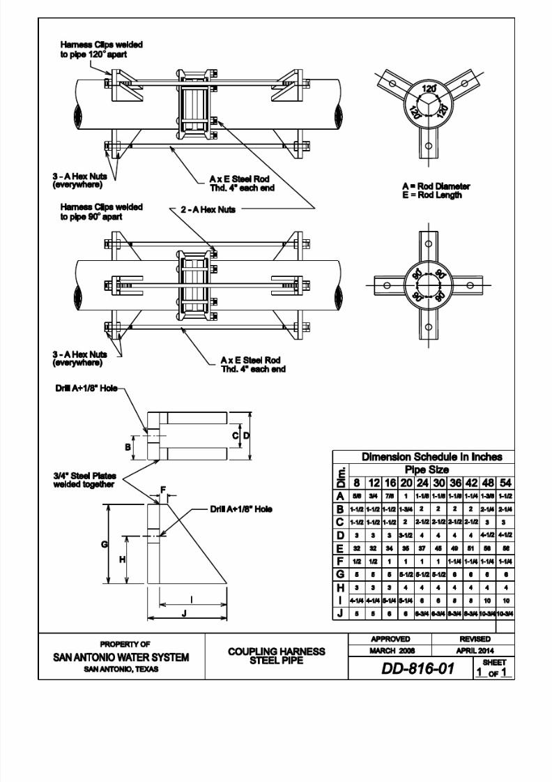
8/21/2019 2014 SAWS Construction Specifications
http://slidepdf.com/reader/full/2014-saws-construction-specifications 90/461
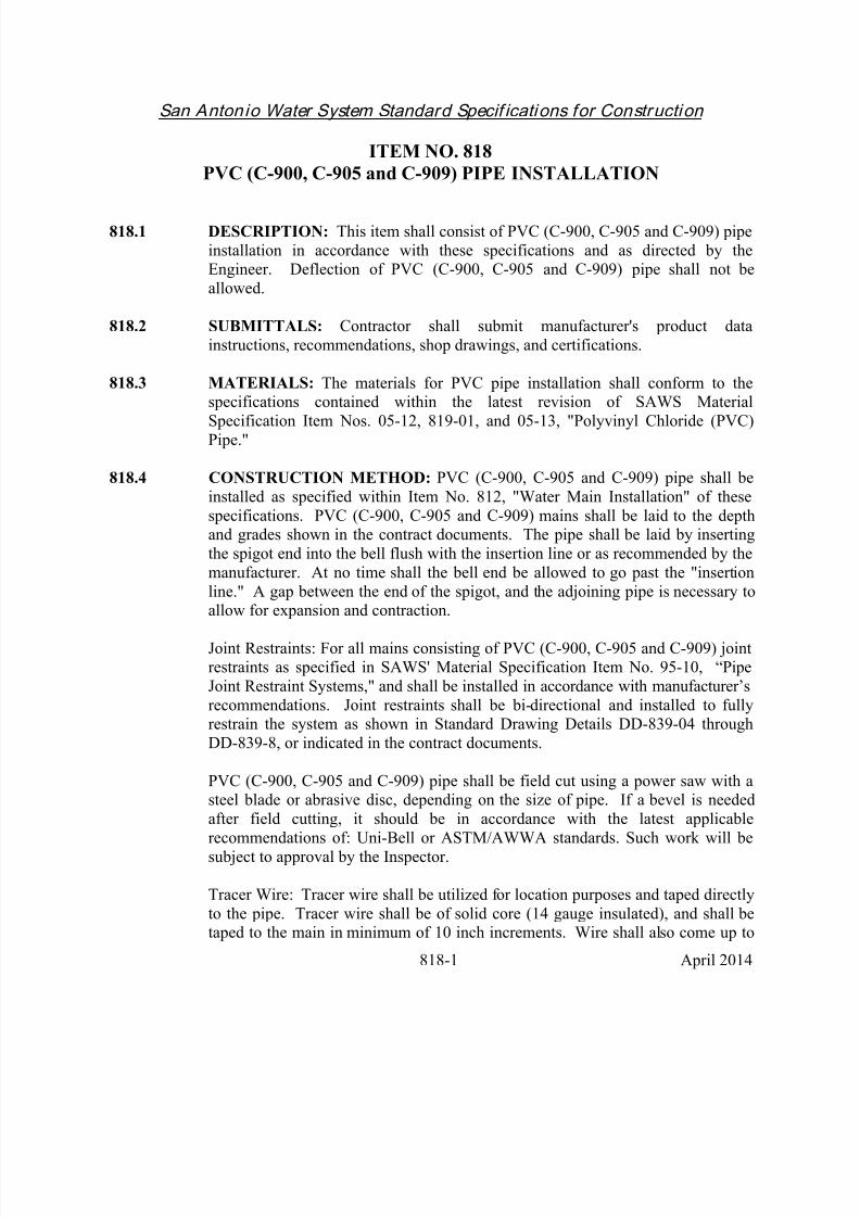
8/21/2019 2014 SAWS Construction Specifications
http://slidepdf.com/reader/full/2014-saws-construction-specifications 91/461
San Antonio Water System Standard Specif ications for Construction
818-1 April 2014
ITEM NO. 818 PVC (C-900, C-905 and C-909) PIPE INSTALLATION
818.1 DESCRIPTION: This item shall consist of PVC (C-900, C-905 and C-909) pipe
installation in accordance with these specifications and as directed by theEngineer. Deflection of PVC (C-900, C-905 and C-909) pipe shall not be
allowed.
818.2 SUBMITTALS: Contractor shall submit manufacturer's product data
instructions, recommendations, shop drawings, and certifications.
818.3 MATERIALS: The materials for PVC pipe installation shall conform to thespecifications contained within the latest revision of SAWS Material
Specification Item Nos. 05-12, 819-01, and 05-13, "Polyvinyl Chloride (PVC)Pipe."
818.4 CONSTRUCTION METHOD: PVC (C-900, C-905 and C-909) pipe shall be
installed as specified within Item No. 812, "Water Main Installation" of these
specifications. PVC (C-900, C-905 and C-909) mains shall be laid to the depthand grades shown in the contract documents. The pipe shall be laid by inserting
the spigot end into the bell flush with the insertion line or as recommended by the
manufacturer. At no time shall the bell end be allowed to go past the "insertion
line." A gap between the end of the spigot, and the adjoining pipe is necessary toallow for expansion and contraction.
Joint Restraints: For all mains consisting of PVC (C-900, C-905 and C-909) jointrestraints as specified in SAWS' Material Specification Item No. 95-10, “Pipe
Joint Restraint Systems," and shall be installed in accordance with manufacturer’s
recommendations. Joint restraints shall be bi-directional and installed to fullyrestrain the system as shown in Standard Drawing Details DD-839-04 through
DD-839-8, or indicated in the contract documents.
PVC (C-900, C-905 and C-909) pipe shall be field cut using a power saw with asteel blade or abrasive disc, depending on the size of pipe. If a bevel is needed
after field cutting, it should be in accordance with the latest applicable
recommendations of: Uni-Bell or ASTM/AWWA standards. Such work will besubject to approval by the Inspector.
Tracer Wire: Tracer wire shall be utilized for location purposes and taped directly
to the pipe. Tracer wire shall be of solid core (14 gauge insulated), and shall betaped to the main in minimum of 10 inch increments. Wire shall also come up to

8/21/2019 2014 SAWS Construction Specifications
http://slidepdf.com/reader/full/2014-saws-construction-specifications 92/461
San Antonio Water System Standard Specif ications for Construction
818-2 April 2014
the top of valve extensions and fire hydrant stems, as directed by the Inspector.
818.5 MEASUREMENT: PVC pipe will be measured by the linear foot for each sizeand type as follows:
Measurements will be from the center line intersection of runs and branches oftees to the end of the valve of a dead end run.
Measurements will also be between the center line intersection of runs and
branches of tees. Where the branch is plugged for future connection, themeasurement will include the entire laying length of the branch or branches of the
fitting.
The measurement of each line of pipe of each size will be continuous and shallinclude the full laying lengths of all fittings and valves installed between the ends
of such line except that the laying length of reducers will be divided equally
between the connected pipe sizes. Lines leading to a tapping connection with anexisting main will be measured to the center of the main tapped.
818.6 PAYMENT: Payment for PVC Pipe installed will be made at the unit price bid per linear foot of pipe of the various sizes installed by the open cut method. Such
payment shall also include excavation, selected embedment material, backfill,
compaction, polyethylene sleeve, hauling and disposition of surplus excavated
material, including all existing pipe, fittings, appurtenances to be abandoned
(where specified or shown in the contract documents).
- End of Specification -

8/21/2019 2014 SAWS Construction Specifications
http://slidepdf.com/reader/full/2014-saws-construction-specifications 93/461
San Antonio Water System Standard Specif ications for Construction
820-1 April 2014
ITEM NO. 820
CONCRETE STEEL CYLINDER PIPE INSTALLATION
820.1 DESCRIPTION: This item shall consist of concrete steel cylinder pipe
installation in accordance with these specifications and as directed by theEngineer.
820.2 SUBMITTALS: Contractor shall submit manufacturer's product data,instructions, recommendations, shop drawings, and certifications.
820.3 MATERIALS: The materials for concrete steel cylinder pipe installation shall
conform to the specifications contained within the latest revision of SAWS'Material Specification Item No. 05-20, "Pre-stressed Concrete Pressure Pipe Steel
Cylinder Type."
820.4 CONSTRUCTION METHOD: Concrete steel cylinder pipe shall be installedas specified within Item No. 812, "Water Main Installation" of these
specifications. Bell holes for concrete steel cylinder pipe shall be of sufficient
size to properly join the pipe and place the required grout. Subject to the above provisions, the length of excavation for bell holes below grade of the trench
bottom shall be kept to a minimum.
820.5 MEASUREMENT: Concrete steel cylinder pipe will be measured by the linear
foot for each size and type as follows:
Measurements will be from the center line intersection of runs and branches of
tees to the end of the valve of a dead end run.
Measurements will also be between the center line intersection of runs and
branches of tees. Where the branch is plugged for future connection, the
measurement will include the entire laying length of the branch or branches of the
fitting.
The measurement of each line of pipe of each size will be continuous and shall
include the full laying lengths of all fittings and valves installed between the endsof such line except that the laying length of reducers will be divided equally between the connected pipe sizes. Lines leading to a tapping connection with an
existing main will be measured to the center of the main tapped.
820.6 PAYMENT: Payment for Concrete Steel Cylinder Pipe installed will be made at

8/21/2019 2014 SAWS Construction Specifications
http://slidepdf.com/reader/full/2014-saws-construction-specifications 94/461
San Antonio Water System Standard Specif ications for Construction
820-2 April 2014
the unit price bid per linear foot of pipe of the various sizes installed by the opencut method. Such payment shall also include excavation, selected embedment
material, backfill, compaction, polyethylene sleeve, hauling and disposition of
surplus excavated material, including all existing pipe, fittings, appurtenances to be abandoned (where specified or shown in the contract documents).
- End of Specification -

8/21/2019 2014 SAWS Construction Specifications
http://slidepdf.com/reader/full/2014-saws-construction-specifications 95/461

8/21/2019 2014 SAWS Construction Specifications
http://slidepdf.com/reader/full/2014-saws-construction-specifications 96/461

8/21/2019 2014 SAWS Construction Specifications
http://slidepdf.com/reader/full/2014-saws-construction-specifications 97/461
8/21/2019 2014 SAWS Construction Specifications
http://slidepdf.com/reader/full/2014-saws-construction-specifications 98/461
San Antonio Water System Standard Specif ications for Construction
821-1 April 2014
ITEM NO. 821
HIGH PRESSURE ZONE DISTRIBUTION SYSTEM
821.1 DESCRIPTION: This item shall govern all construction work performed in
SAWS' high pressure water distribution system, including water mains, services,fire hydrants, and all related appurtenances, and shall be performed in accordance
with current SAWS standard specifications. This specification shall apply solely
to the construction of high pressure water systems and shall govern when in
conflict with other sections of the SAWS standard specifications.
1. High Pressure Systems: Each of the water distribution systems that furnish
water in Pressure Zone 9 through Pressure Zone 16 shall be designed as a
high pressure system. The static water pressure in each of these Service
Levels shall be not less than 35 psi nor exceed 175 psi with no firehydrants in use.
2. Locations of High Pressure Levels: Geographically, the boundaries of
Pressure Zones 9 through 16 conform to the surface contour tabulation
shown in Table HP-1, High Pressure Levels. Most of the area withinPressure Zones 9 through 16 is located north of Loop 1604 between IH 35
North and Bandera Road.
821.2 MATERIAL AND SUPPLIES:
1. General: Construction materials and supplies shall be furnished inaccordance with all applicable provisions outlined in the SAWS' MaterialSpecifications and as supplemented or revised by conditions noted in this
specification.
2. Pipe Materials: Ductile Iron, Concrete Steel Cylinder, PVC class 200(DR14), and Steel pipe shall be used for water main construction in the
High Pressure Distribution System.
821.3 TRENCH EXCAVATION: All excavation shall be performed in accordance
with Item No. 804, "Excavations, Trenching and Backfill."
821.4 PIPE LAYING: Pipe installation shall be performed in accordance with Item No.812, "Water Main Installation."

8/21/2019 2014 SAWS Construction Specifications
http://slidepdf.com/reader/full/2014-saws-construction-specifications 99/461
San Antonio Water System Standard Specif ications for Construction
821-2 April 2014
821.5 SETTING VALVES, FITTINGS, AND FIRE HYDRANTS:
1. General: Valves, fittings, fire hydrants, plugs, and caps shall be set in
accordance with Item Nos. 826, 830, 832, and 836 of these specifications.
2. Valves: All valves shall be supported on a concrete pad in accordance with
Standard Drawing Nos. DD-828-01through DD-828-03.
3. Fire Hydrants: All fittings for fire hydrant installations such as ties, bends,
nipples, valves, and hydrants shall have anchored or flange type joints.
The bowl of each hydrant and valve shall rest on a concrete pad as shownon Standard Drawing DD-834-01. The main line fire hydrant tee shall be
an anchored tee that is properly blocked.
4. Thrust Blocking: All thrust blocking placed in conjunction with mains andappurtenances constructed in Pressure Zones 9 through 16 shall be in
accordance with Standard Drawings DD-839-01 and DD-839-02. In all
cases, the design of thrust blocking shall be of sufficient size, based uponan assumed soil lateral load bearing capacity of 3,000 psi unless specified
otherwise in the contract documents. The maximum soil pressure value
that will be allowed for the design of thrust blocking shall be 5,000 psiwhen specifically requested by the Contractor and approved by the
Engineer. When soil pressure bearing values of 4,000 psi or 5,000 psi are
recorded for design of thrust blocks, copies of soil test made for
determining the bearing value of the subject soil in question shall be
submitted to the Engineer for approval.
821.6 TRENCH BACKFILL: All backfill material shall be placed in accordance withitem No. 804, "Excavation, Trenching, and Backfill" of these specifications.
821.7 CLEANUP: Cleanup of the area of the construction operations shall be in
accordance with these specifications.
821.8 FLUSHING AND TESTING MAINS: All flushing and hydrostatic testing shall
be conducted in accordance with Item No. 841, "Hydrostatic Testing Operations"of these specifications, with the exception that the maximum test pressure shall be
established at 200 psi.
821.9 DISINFECTION OF NEW MAINS UTILIZING MACHINE
CHLORINATION: Disinfection of new mains by machine chlorination shall be
accomplished in accordance with Item No. 847, "Disinfection" of these
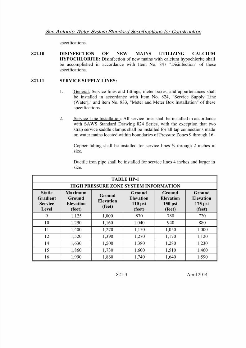
8/21/2019 2014 SAWS Construction Specifications
http://slidepdf.com/reader/full/2014-saws-construction-specifications 100/461
San Antonio Water System Standard Specif ications for Construction
821-3 April 2014
specifications.
821.10 DISINFECTION OF NEW MAINS UTILIZING CALCIUM
HYPOCHLORITE: Disinfection of new mains with calcium hypochlorite shall be accomplished in accordance with Item No. 847 "Disinfection" of these
specifications.
821.11 SERVICE SUPPLY LINES:
1. General: Service lines and fittings, meter boxes, and appurtenances shall
be installed in accordance with Item No. 824, "Service Supply Line(Water)," and item No. 833, "Meter and Meter Box Installation" of these
specifications.
2. Service Line Installation: All service lines shall be installed in accordancewith SAWS Standard Drawing 824 Series, with the exception that two
strap service saddle clamps shall be installed for all tap connections made
on water mains located within boundaries of Pressure Zones 9 through 16.
Copper tubing shall be installed for service lines ¾ through 2 inches in
size.
Ductile iron pipe shall be installed for service lines 4 inches and larger in
size.
TABLE HP-1HIGH PRESSURE ZONE SYSTEM INFORMATION
Static
Gradient
Service
Level
Maximum
Ground
Elevation
(feet)
Ground
Elevation
(feet)
Ground
Elevation
110 psi
(feet)
Ground
Elevation
150 psi
(feet)
Ground
Elevation
175 psi
(feet)
9 1,125 1,000 870 780 720
10 1,290 1,160 1,040 940 880
11 1,400 1,270 1,150 1,050 1,000
12 1,520 1,390 1,270 1,170 1,120
14 1,630 1,500 1,380 1,280 1,230
15 1,860 1,730 1,600 1,510 1,460
16 1,990 1,860 1,740 1,640 1,590
8/21/2019 2014 SAWS Construction Specifications
http://slidepdf.com/reader/full/2014-saws-construction-specifications 101/461
San Antonio Water System Standard Specif ications for Construction
821-4 April 2014
821.12 MEASUREMENT: High pressure zone distribution system will not be measured
for payment.
821.13 PAYMENT: No direct payment shall be made for incidental costs of material or
effort associated with this specification.
- End of Specification -

8/21/2019 2014 SAWS Construction Specifications
http://slidepdf.com/reader/full/2014-saws-construction-specifications 102/461
San Antonio Water System Standard Specif ications for Construction
822-1 April 2014
ITEM NO. 822 CUSTOMER ’S WATER YARD PIPE
822.1 DESCRIPTION: This item shall consist of customer yard piping adjustmentsand installation in accordance with these specifications and as directed by the
Engineer.
822.2 MATERIALS: The materials for customer yard piping adjustments and
installation shall conform to the specifications contained within the latest revision
of SAWS' Material Specification Item Nos. 15-01, "Copper Tubing," and 15-40,
"Brass Goods."
822.3 CONSTRUCTION:
1. Designation of Yard Piping: New copper yard piping shall be installedwithin the limits of the Customer's property in conjunction with all small
service lines relocated from existing mains in the alleyways behind
Customer residences to street rights-of-ways fronting Customerresidences. See Standard Drawing DD-822.
Customer yard piping begins from the outlet meter connection to the point
of connection within the limits of the Customer's lot or property.
"Short yard piping," shall be described as consisting of customer's yard
piping that does not exceed one-half the depth of the lot.
"Long yard piping," shall be described as consisting of customer's yard
piping that, when installed, exceeds one-half depth of the lot.
2. Materials: All ¾ inch through 2 inch yard piping shall be furnished by the
Contractor and shall be Type "K", soft annealed copper water tubing.
Plastic round Customer cut-off valve boxes furnished by the Contractorshall consist of a box and cover, shall accommodate cut-off valves up to 2
inches, and shall be by a SAWS-approved manufacturer.
The Contractor shall also furnish all materials to include pipes, nipples,unions, couplings, tees, elbows, street ells, hose bibs, insulation for riser
pipe, caps, plugs and appurtenances required to complete the tie of
Customer's new yard piping at the new point of connection and theabandonment of the Customer's old yard piping at the old point of
connection, as no separate pay item. Where dissimilar materials are to be

8/21/2019 2014 SAWS Construction Specifications
http://slidepdf.com/reader/full/2014-saws-construction-specifications 103/461
San Antonio Water System Standard Specif ications for Construction
822-2 April 2014
connected, the Contractor shall install a PVC Schedule 80 insulator
coupling.
3.
Installation: Work involved with replacing existing yard piping shallconsist of several key components as listed:
a. Excavation of miscellaneous material encountered;
b. Installation of the new copper yard piping with 12 inches of cover
minimum and in the most direct and practicable alignment;
c. Brass fittings;
d. Customer's cut-off valve and the Customer's cut-off valve meter
box;
e. Reconnection of the Customer's service at the relocated meter andthe new point of connection within the limits of the Customer's
property;
f. Abandoning the Customer's old yard piping by cutting and plugging the old yard piping at the old point of connection within
the limits of the Customer's property;
g. Backfilling the trench with approved selected material and disposal
of surplus excavated material;
h. Replacement of surfaces of all types over the completed yard piping trench with approved selected material and disposal of
surplus excavation material;
i. Restoration of the site. Existing trees, plants or shrubbery within
the Customer ’s property shall not be disturbed. Any existing
landscape that necessitates removal, in order for the scope of workto be completed, shall be replaced to the satisfaction of the
inspector and customer;
j. Acquiring any permits to do this scoped work on the customer’s property.
When the presences of manifold systems are encountered, the Contractor
shall install and tie-in Customer yard piping at the existing point of

8/21/2019 2014 SAWS Construction Specifications
http://slidepdf.com/reader/full/2014-saws-construction-specifications 104/461
San Antonio Water System Standard Specif ications for Construction
822-3 April 2014
connection. Lawn sprinklers are a possible indication of existing manifold
systems. All exposed risers shall be protected from freezing temperatures
by means of keeping them no less than 6 inches below ground surface to
the tie-in. Trench excavation may be accomplished either manually,mechanically (such as usage by a "Ditch Witch"), or by other similar
mechanical trenching equipment. If mechanical trenching equipment is
utilized, depressions or damage to lawn areas caused by crawler track padsor pneumatic tires shall be repaired and restored to their original condition.
Lawn turf over the trench shall be removed squarely to a depth of 2 inchesand in lengths not to exceed 36 inches. Lawn turf removed and material
excavated from the trench area shall not be placed directly upon existing
lawn turf areas, but rather, they shall be separated and placed on building
paper or plastic membrane. Building paper or plastic membrane shall
cover the existing lawn turf adjacent and parallel to the alignmentfollowed by the trench. After the installation of the yard piping, the trench
shall be backfilled and adequately tamped in two compacted lifts of 5inches and watered. The lawn turf shall be replaced, adequately tamped,
and thoroughly watered after surplus soil is removed. Customer's yard
piping shall be flushed prior to final tie-in at the existing point of
connection.
822.4 MEASUREMENT: "Customer's Yard Piping" will be measured by the linear
foot of the various types and sizes of Customer's yard piping installed.
822.5 PAYMENT: Payment for "Customer's Yard Piping" will be made at the unit price bid per each linear foot of Customer's new yard piping installed. Payment
shall be made under item "Short yard piping" or "Long yard piping."
Such payment shall also include: excavation, hauling and disposition of surplus
material, approved backfill material, removal and replacement of Customer's lawnturf, permits, and whatever other surface vegetation/landscaping and surface
structure encountered, copper tubing, and brass fittings of necessary size to
complete the tie at the Customer's point of connection.
- End of Specification -

8/21/2019 2014 SAWS Construction Specifications
http://slidepdf.com/reader/full/2014-saws-construction-specifications 105/461

8/21/2019 2014 SAWS Construction Specifications
http://slidepdf.com/reader/full/2014-saws-construction-specifications 106/461
San Antonio Water System Standard Specif ications for Construction
823-1 April 2014
ITEM NO. 823 DIRECTIONAL BORING FOR
CUSTOMER’SWATER YARD PIPE
823.1 DESCRIPTION: This item shall govern the furnishing and installation ofcustomer yard piping and conduit by the method of directional boring as shown in
the contract documents and as directed by the Engineer.
823.2 MATERIALS:
1. The materials for customer yard piping installation and adjustment shall
conform to the specifications contained within the latest revision of
SAWS’ Material Specification Item Nos. 15-01, “Copper Tubing,” and15-40, “Brass Goods.”
2. The polyvinyl chloride (PVC) conduit shall be Schedule 80 or Certa T-Lock PVC, where applicable, and shall conform to the latest provision of
ASTM D1785 or most applicable approved equal provision. The fittings
for the PVC pipe shall be Schedule 80 and shall be in accordance with thelatest provision of ASTM D2467 or most applicable approved equal
provision.
823.3 CONSTRUCTION:
1. Determination for Directional Boring Method: Directional boring method
shall be used for installations of customer’s “short yard piping” or “longyard piping” when open-cut method is not feasible. Refer to Item No.
822.3.1, “Designation of Yard Piping.” Directional boring method should
be used to avoid disruption to items such as, but not limited to, substantial
landscaping, trees, driveways, retaining walls, privacy walls, structures, orsprinkler systems that cannot be economically be replaced, or as directed
by the Inspector. The yard piping shall be placed in 2 inch or 4 inch inside
diameter (I.D.) PVC conduit as appropriate when directed by theInspector.
2. Designation of Yard Piping: Refer to Item No. 822.3.1.
3. Materials: Refer to Item No. 822.3.2.
4. Installation: Directional Boring Method machine as manufactured by

8/21/2019 2014 SAWS Construction Specifications
http://slidepdf.com/reader/full/2014-saws-construction-specifications 107/461
San Antonio Water System Standard Specif ications for Construction
823-2 April 2014
“Ditch Witch,” “Vermeer ,” or other approved equal, capable of drilling a
minimum of a 300 feet continuous bore.
Refer to Item No. 822.3.3 for installation procedures for customer yard piping.
Directional boring shall be completed with the use of a directional boring
machine, as manufactured by “Ditch Witch”, “Vermeer ,” or other approved equal.The directional boring machine shall be supplied with an output signal inside the
housing of the drill bit. The output signal shall have a constant output signal to
allow a person to track the location of the beacon at all times. The drill bit shall be located a maximum of every 5 feet for exact location of the service line to be
pulled in. When bore is completed, contractor shall provide SAWS with a pilot of
the bore path.
The drilling machine shall be set up at such a location to avoid disruption of private yard and landscaping. The operator of the drilling unit shall check the
bore path and position of boring pit at every five feet and make necessarycorrection to stay along the alignment. The pilot hole shall not be greater than 4
inches in diameter, except when a 4inch PVC conduit is installed. The Contractor
shall make necessary provisions to keep water and soil out of the installed yard
piping.
The drilling machine shall be equipped with a drilling fluid compatible for the
onsite conditions. The fluid, such as bentonite, shall be used for lubricating the pipe during pull-back, forcing spoils out of the pipe pit, assisting in holding the
hole open during pull back, and hardening into a clay substance around theoutside of the conduit, preventing settlement of the ground. Adequate drilling
fluids shall be used to avoid a “hydra-lock” condition. The directional head shall be capable of accepting a variety of cutting bits for varied soil conditions.
Any damage to customer’s property, landscaping or trees caused by theContractor’s activities of installing yard piping, shall be replaced to both the
inspector’s and customer’s satisfaction, at no additional cost to SAWS.
Contractor shall take a video DVD recording of the entire project area prior to
commencing any work in the area. A DVD video shall be turned into SAWS for
review and approval before starting any work, including mobilization and preparation of right-of-way.
823.4 MEASUREMENT: Directional Boring for Customer’s Yard Piping” will be
measured by the linear foot of the various types and sizes of customer’s yard
piping or conduit installed.

8/21/2019 2014 SAWS Construction Specifications
http://slidepdf.com/reader/full/2014-saws-construction-specifications 108/461
San Antonio Water System Standard Specif ications for Construction
823-3 April 2014
823.5 PAYMENT: Payment for “Directional Boring for Customer’s Yard Piping” will
be made at the unit price bid for each linear foot of customer’s new yard piping or
conduit installed. Payment for customer yard piping shall be made under item“Yard piping – directional bore method”. When the yard piping is installed in
conduit it shall be paid under items 2 inch I.D. PVC conduit – directional bore
method, and “yard piping installed in conduit”, or items 4 inch I.D. PVC conduit – directional bore method” and yard piping installed in conduit
Such payment shall include excavation, hauling and disposition or surplusmaterial, approved backfill material, removal and replacement of customer’s lawn
turf and whatever other surface vegetation and surface structure encountered,
copper tubing, PVC conduit, and brass fittings or whatever size necessary to
complete the tie at the customer’s point of connection.
- End of Specification -

8/21/2019 2014 SAWS Construction Specifications
http://slidepdf.com/reader/full/2014-saws-construction-specifications 109/461
San Antonio Water System Standard Specif ications for Construction
824-1 April 2014
ITEM NO. 824
WATER SERVICE SUPPLY LINES
824.1 DESCRIPTION: This item shall consist of water service supply linesadjustment and installation in accordance with these specifications and as directed by the Engineer.
824.2 MATERIALS: The materials for water service supply lines installation andadjustment shall conform to the specifications contained within the latest revisionof SAWS' Material Specification Item Nos. 21-10, "Brass Gate Valves,"15-40,"Brass Goods," 15-01, "Copper Tubing," and 100-30, "Service Saddles."
824.3 CONSTRUCTION:
1. General: Service supply lines and fittings, meter boxes and appurtenancesshall conform to the Material Specifications and shall be installed by theContractor as specified herein, or as directed by the Engineer and inaccordance with the DD-824 Standard Drawing Series.
2. Designation of Service Supply Lines: A service supply line located between the water main and the inlet side of the water meter is designatedas a "water service line." A service supply line located between the outletside of the water meter to the point of connection within the limits of theCustomer's lot or property is designated as the "Customer's yard piping"
and is covered under Item No. 822 of these specifications. Services 2inches and smaller are designated "small services." Services 4 inches andlarger are designated "large services."
3. Service Relays: New transfer main(s) to which services are to be relayed,and are on the same side of the streets as the Customer's meter, are definedas "short relays." New transfer main(s) to which services are to berelayed, and are on the opposite side of the street from the Customer'smeter, are defined as "long relays."
Service Reconnects: New transfer main(s) to which services are to bereconnected, and on the same side of the street as the old main, are definedas "short reconnects." Existing services on the opposite side of the streetto the new main shall be defined as a "long reconnects."
4. Service Relocates: Service Relocates are defined as services that arerelocated from an alley or street to a side or front street. New transfermain(s) to which services are to be relocated, and are on the same side of

8/21/2019 2014 SAWS Construction Specifications
http://slidepdf.com/reader/full/2014-saws-construction-specifications 110/461
San Antonio Water System Standard Specif ications for Construction
824-2 April 2014
the street as the Customer's new meter box location, are designated as"short relocates." New transfer main(s) to which services are to berelocated, and are on the opposite side of the street from the Customer's
new meter box location, are designated as "long relocates."
5. New Services: If a new main is required to be extended to provide waterservice for new Customers, the service lines laid to the new main shall bedesignated as "new services." New laid main(s) to which new services areon the same side of the street as the Customer's new meter box location,are designated as "new short services." New laid main(s) to which newservices on the opposite side of the street from the Customer's new meter box location, are designated as "new long services."
6. New Unmetered Services: New unmetered services are defined as
services that are installed on existing or new mains to provide service to platted vacant lots. Where the new or existing main to which newunmetered services are being installed, is on the same side of the street asthe Customer's new or existing meter box location (Inspector is to setlocation of new meter box if no existing meter box is set), the services to be laid are designated "new unmetered short services." Where the new orexisting water main to which new unmetered services are installed, is onthe opposite side of the street from the Customer's new or existing meter box location (Inspector is to set location of new meter box if no existingmeter box is set), the services to be laid are designated "new unmeteredlong service." New unmetered long services and new unmetered shortservices will not include "Customer's yard piping," and no meter will be
set.
7. Tap Holes: Tap holes are defined as excavations at existing mains, whichare required in association with replacements of water service lines by pulling, boring or jacking operations.
All backfill material shall be as specified for all associated main andservice line trench excavation.
For service lines and tap holes, payment for bedding, initial backfill andsecondary backfill shall be included in the various sizes of each service
placed.
8. Service Line Installation: Unless otherwise notified, service relays,service reconnects, service relocates and new services shall be installed asdescribed herein, and in the DD-824 Standard Drawing Series. Unlessotherwise indicated, existing meter and meter box relocation shall be

8/21/2019 2014 SAWS Construction Specifications
http://slidepdf.com/reader/full/2014-saws-construction-specifications 111/461
San Antonio Water System Standard Specif ications for Construction
824-3 April 2014
included in the service line installation.
All service line installation shall include a dielectric union to be installed
within the meter box on the outlet side of the meter, as shown in the DD-824 Standard Drawing Series.
Cutting, excavation, backfill and replacement of pavement shall be doneas specified herein and in accordance with applicable sections of the Cityof San Antonio Specification Item No. 511, "Cutting and ReplacingPavements (Trench Repair), and Item No. 804, "Excavation, Trenching,and Backfill." The minimum trench width for small service lines shall be8 inches, while the minimum trench width for large service lines shall bethe nominal pipe diameter plus 16 inches, except when specified otherwise by the Engineer. For ¾ inch to 2 inch Service lines, the minimum bury
depth shall be 3 feet. For services greater than 2 inches, the minimumdepth of bury shall be 4 feet.
All service lines shall be installed in accordance with the DD-824Standard Drawing Series, SAWS' Standard Material Specification Item No. 100-30, except that two strap service saddle clamps shall be installedfor all tap connections made on water mains located within boundaries ofPressure Zones 9 through 16.
The Contractor shall use precaution to protect and preserve the polyethylene wrap around ductile-iron water mains when installing servicecorporations. The required method is: wrap pipe tape around the pipe,
over the polywrap, in the area to be tapped. The tap shall be made throughthe tape and polywrap. It is not necessary to remove and replace polywrap. All exposed pipe, corporation, and the first three feet of theservice, shall be wrapped and taped to achieve a complete seal. Inaddition, a sand envelope shall extend over and around the connection to adepth of 8 inches above the main.
Small service lines shall be embedded in sand in accordance with Item No.804, "Excavation, Trenching and Backfill."
When approved by the Inspector, the Contractor may lay the new service
line from the corporation stop to the curb stop or angle valve. Uponcompletion, the Contractor shall isolate the new service line by closing thecurb stop or angle valve until the meter box is set.
9. Splicing: A long service line single slice may be permitted by means of a3-part compression or flared coupling only when approved in advance by
8/21/2019 2014 SAWS Construction Specifications
http://slidepdf.com/reader/full/2014-saws-construction-specifications 112/461
San Antonio Water System Standard Specif ications for Construction
824-4 April 2014
the Inspector, provided the location of the splice is not under pavement orconcrete. The segment added is required to be the same material as theexisting service line, unless otherwise directed by the Inspector. Splicing
short service lines will not be permitted.
10. Boring or Jacking Service Lines: Service lines which cross paved streetsmay be installed at the Contractor's option by boring or jacking operations.Where it becomes necessary to widen the main trench section toaccommodate a bore pit, such widening shall not extend more than oneadditional foot into the traffic side of the street.
11. Tapping Asbestos Cement (AC)Pipe: All necessary service line tapping ofAC pipe shall be completed during the period immediately before or afterhydrostatic pressure testing operations so that subsequent flushing will
maximize the elimination of contaminants associated with the tapping process. Direct tapping will not be allowed. Service saddles must be usedwhen tapping AC pipe. Drill tools shall be used for services less than 2inches. Shell type drills shall be used for all services 2 inches and greater.
The tapping of AC pipe must be done in accordance with manufacturers’
recommendations and done only with tap machine having a built in flushvalve and the flush valve must be open during the entire procedure.
12. Abandonment of Service Lines: The Contractor shall accomplish allcutting, capping, and plugging necessary to isolate new service linestransferred to new and existing mains from those abandoned, including
service lines designated in the contract documents as "tap plug" and "tapkill." The corporation stop for an abandoned service line tapped on aferrous main shall be removed, and the tap at the main shall be pluggedwith an appropriately sized brass plug. For a non-ferrous main, thecorporation stop shall not be removed from the main. Instead, thecorporation stop shall be closed and the flared nut shall be removed fromthe corporation stop. After the appropriately sized copper disc is insertedinside the flared nut, replace the flared nut on the corporation stop. TheContractor shall salvage copper service line tubing, brass fittings, andother materials as directed by the Inspector and return them to the Owner.
13. Tapping PVC (C-900) Pipe: Tapping of PVC pipe must be done inaccordance with Uni-Bell procedures. Direct tapping will not be allowed.All drill cutting tools must be the "shell type" with internal teeth or doubleslots which will retain the coupon. The shell cutters must be designed forC-900 pipe, thus having sufficient root depth to handle the heavier walled pipe.

8/21/2019 2014 SAWS Construction Specifications
http://slidepdf.com/reader/full/2014-saws-construction-specifications 113/461
San Antonio Water System Standard Specif ications for Construction
824-5 April 2014
14. Small Service Lines: Copper tubing shall be used for ¾ inch through 2inch service lines. Brass fittings for ¾ inch and 1 inch service lines shall
be of the flared or compression type for the use with Type 'K' softannealed copper tubing. Brass fittings for 1½ inch and 2 inch lines shall be of the flared or compression type for use with type 'K' soft annealedcopper tubing, except as modified by subsection No. 824.39.
Copper tubing shall be cut squarely by using an approved cutting tool and by avoiding excessive pressure on the cutting wheels which might bend orflatten the pipe walls. Following the copper tubing cut, but before flaring,a reamer shall be used to remove the inside rolled lip from the tubing.Flared ends shall be expanded by the use of a flaring tool using care toavoid splitting, crimping, or overstressing the metal. Pipe adjacent to the
fittings shall be straight for at least 10 inches. Bending of tubing shall beaccomplished by using an appropriate sized bending tool. No kinks, dents,flats, or crimps will be permitted, and should such occur, the damagedsection shall be cut out and replaced. When compression fittings are used,the copper tubing shall be cut squarely prior to insertion into the fitting.Final assembly shall be in accordance with the manufacturer'srecommendations.
15. Small Service Lines on New Mains: Installation of new copper servicelines shall consist of all excavation through miscellaneous materialencountered; trench excavation protection; drilling and tapping the newmain with an approved tapping machine; setting the curb stop or angle
valve at the meter; laying the new copper service line at the specifieddepth between the main and the meter and its tie-in at the corporation andthe curb stop or the angle valve; relocating the existing meter andinstalling a new meter box in accordance with Item No. 833, "Meter andMeter Box Installation."; backfilling the trench with approved selectedmaterial and disposal of surplus excavated material; capping the tap holewith asphalt treated base, including the outer limits of the main trench linewith service line trench; cutting and replacing pavements, curbing andsidewalks of all types over the limits of the main line trench and thecompleted service line trench.
16. Reconnecting Service Lines: Both old and new water mains at existingservice line connections, as shown in the contract documents, shall beexposed. The old main shall be exposed for the purpose of gaining accessto the existing service corporation stop and the new main for the purposeof installing the new corporation stop. The new main shall be exposed forthe purpose of being drilled and tapped with an approved tapping machine,

8/21/2019 2014 SAWS Construction Specifications
http://slidepdf.com/reader/full/2014-saws-construction-specifications 114/461
San Antonio Water System Standard Specif ications for Construction
824-6 April 2014
a new corporation stop installed under pressure, and the trench extendedlaterally to expose a sufficient length of the existing service line to provideslack to bend it into position for tying to the new corporation stop. After
suitable notification to the Customer, the Contractor shall "kill" theexisting service by closing the corporation stop, removing the existingflare nut, inserting inside the existing flared nut an appropriately-sizedcopper disc and replacing the existing flared nut on the corporation stop ifthe main is non-ferrous, or plugging the existing service line at the main ifthe main is ferrous. The Contractor shall then immediately open the stopand restore water service to the Customer. Where it is not possible toobtain sufficient length in the existing service to tie directly to the newmain, at the direction of the Inspector, the Contractor shall splice thenecessary length of new tubing and tie it to the existing service by meansof a compression coupling at a point as close as practicable to the new
main.
Cutting and bending of the tubing, introduction of slack to compensate forsoil movement, and completion of the installation shall be as specified insubsection No. 824.17, "Relaying Service Lines."
Where old and new mains are on opposite sides of the street, service linesmay be installed under the street pavement by boring rather thantrenching.
17. Relaying Service Lines: The existing or new mains shown in the contractdocuments shall be exposed and opposite location stakes placed onsite at
the direction of the Inspector. The existing or new main shall: be drilledand tapped with an approved tapping machine, a new corporation stopinstalled, and the trench extended laterally to the location specified for themeter box. The existing meter shall be reset and the meter box and baseshall be installed at its staked location and perpendicular to the corporationstop in the water main. The meter box location shall not vary more than24 inches in any direction from its staked location. The service line shall be installed with sufficient slack to compensate for soil movement. Wherethe location of the existing meter is not changed, the new service line shall be extended from the main to the existing meter, a new curb stop installedat the end of the service line, and connected to the inlet side of the meter.
If disturbed, the existing meter box shall be reset to correct grade. Longservice relays may be placed under the street pavement by boring or jacking rather than trenching.
18. Single Service Line - Dual Meters: The single service line - dual meterinstallation shall consist of a 1" copper service line reducing to two ¾inch

8/21/2019 2014 SAWS Construction Specifications
http://slidepdf.com/reader/full/2014-saws-construction-specifications 115/461
San Antonio Water System Standard Specif ications for Construction
824-7 April 2014
copper service lines at a tee which shall be set in line with the front edgeof meter boxes for ⅝inch and ¾inch meters. A single service line withdual meters shall be installed in those new residential developments where
new ⅝inch and ¾inch meters are required and in main replacement work,where it is necessary to change the location of existing ⅝inch and ¾inchmeters. Single service line - dual meter materials and installationrequirements shall conform to requirements established herein SeeDD824-05 Standard Drawing Series.
19. Small Service Lines on Existing Mains: The work involved in theinstallation of new copper service lines on existing mains shall consist of jacking, boring, tunneling, and, where authorized, open trench operations;all excavation through whatever material encountered; trench excavation protection; using the existing corporation when approved by the Inspector;
tapping the existing main and installing the new corporation and settingthe curb stop or angle valve at the meter; relocating the existing meter andinstalling a new meter box in accordance with Item No. 833, "Meter andMeter Box Installation;" abandoning the existing corporation stop,removing the existing flared nut, inserting inside the existing flared nut anappropriately-sized copper disc and replacing the existing flared nut on thecorporation stop, if the main is non-ferrous, or plugging the existingservice line at the main if the main is ferrous; installing the new serviceline at the same grade as the existing service line or at the specified grade between the main and the existing meter and its tie-in at the corporationand the curb stop; disposal of surplus excavated material; capping the taphole with asphalt treated base including the outer limits of the main line
trench and the service line trench; cutting and replacing all surfaces ofwhatever type encountered over the completed service line trench;restoration of the site.
20. Large Service Lines: Ductile iron pipe and cast iron fittings used formetered service lines and non-metered fire service lines larger than 2inchshall be installed in accordance with the applicable provisions of Item No.812, "Water Main Installation," except where otherwise approved by theEngineer.
21. Large Service Lines on New Mains: Work involved in the installation of a
new metered service lines and non-metered fire service lines shall consistof all excavation through whatever material encountered, trenchexcavation protection, installing tees, pipe and fittings of various sizesincluding main line and service line valves, valve boxes, ductile iron pipe,fittings, in accordance with the associated DD-824 Standard DrawingSeries, and reaction block, backfilling with approved selected material,

8/21/2019 2014 SAWS Construction Specifications
http://slidepdf.com/reader/full/2014-saws-construction-specifications 116/461
San Antonio Water System Standard Specif ications for Construction
824-8 April 2014
cutting and replacing pavements, curbing, and sidewalks of all types overthe limits of the main line trench and the completed ductile iron serviceline.
22. Large Service Lines on Existing Mains: The work involved in theinstallation of the new metered service lines and non-metered fire servicelines shall consist of all excavation through whatever materialencountered, trench excavation protection, cutting-in tees and installingtapping sleeves and valves, pipe and fittings of various sizes includingmain line and service valves, valves boxes, ductile iron pipe, fittings andreaction block required, backfilling with approved selected material,cutting and replacing pavements, curbing, and sidewalks of all types overthe limits of the main line trench and the completed ductile iron serviceline.
824.4 MEASUREMENT:
1. Reconnect Short Service will be measured by the unit of the various typesand sizes of each service line reconnected.
2. Relay Short Service will be measured by the unit of the various types andsizes of each service line relayed.
3. Relay Long Service will be measured by the unit of the various types andsizes of each service line relayed.
4. Relocate Short Service will be measured by the unit of the various typesand sizes of each service line relocated.
5. Relocate Long Service will be measured by the unit of the various typesand sizes of each service line relocated.
6. New Short Service will be measured by the unit of the various types andsizes of each new service line installed.
7. New Long Service will be measured by the unit of the various types andsizes of each new service line installed.
8. New Un-metered Short Service will be measured by the unit of the varioustype and sizes of each new un-metered service line installed.
9. New Un-metered Long Service will be measured by the unit of the varioustype and sizes of each new un-metered service line installed.

8/21/2019 2014 SAWS Construction Specifications
http://slidepdf.com/reader/full/2014-saws-construction-specifications 117/461
San Antonio Water System Standard Specif ications for Construction
824-9 April 2014
824.5 PAYMENT: Payment for a Reconnect will be made at the unit price for eachservice line of the various sizes reconnected. Such payment shall also include
excavation, trench excavation protection, hauling and disposition of surplusexcavated materials, sand backfill, cutting pavement and surface structures ofwhatever type encountered and replacement with whatever type specified, andcopper tubing and fittings of the various sizes used in the service linereconnection.
Payment for a Relay Short and Long Service will be made at the unit price foreach service line of the various sizes relayed. Payment shall include reconnectionof new service to the existing meter and the adjustment of the meter, meter box,and Customer valve. Such payment shall also include excavation, trenchexcavation protection, hauling and disposition of surplus excavated materials,
sand backfill, cutting pavement and surface structures of whatever typeencountered and replacement with whatever type specified, and copper tubing andfittings of the various sizes used in the service line relay.
Payment for a Relocate Short and Long Service will be made at the unit price bidfor each service line of the various sizes relocated. Such payment shall alsoinclude excavation, trench excavation protection, hauling and disposition ofsurplus excavated materials, sand backfill, meter box relocation, cutting pavementand surface structures of whatever type encountered and replacement withwhatever type specified, and copper tubing and fittings of the various sizes usedin the service line relocation.
Payment for a New Short and Long Service will be made at the unit price bid foreach new service line of the various sizes installed. Such payment shall alsoinclude excavated materials, trench excavation protection, sand backfill, cutting pavement and surface structures of whatever type encountered and replacementwith whatever type specified, meter box, meter template, copper tubing andfittings of the various sizes used in the new service line installation.
Payment for a New Unmetered Short and New Unmetered Long Service will be
made at the unit price bid for each new unmetered service line of the various sizes
installed. Such payment shall also include excavated materials, trench excavation protection, sand backfill, cutting in pavement and surface structures of whatever
type encountered and replacement with whatever type specified, meter box, metertemplate, copper tubing and fittings, of the various sizes used in the new un-
metered service line installation.
- End of Specification -

8/21/2019 2014 SAWS Construction Specifications
http://slidepdf.com/reader/full/2014-saws-construction-specifications 118/461

8/21/2019 2014 SAWS Construction Specifications
http://slidepdf.com/reader/full/2014-saws-construction-specifications 119/461

8/21/2019 2014 SAWS Construction Specifications
http://slidepdf.com/reader/full/2014-saws-construction-specifications 120/461

8/21/2019 2014 SAWS Construction Specifications
http://slidepdf.com/reader/full/2014-saws-construction-specifications 121/461

8/21/2019 2014 SAWS Construction Specifications
http://slidepdf.com/reader/full/2014-saws-construction-specifications 122/461

8/21/2019 2014 SAWS Construction Specifications
http://slidepdf.com/reader/full/2014-saws-construction-specifications 123/461

8/21/2019 2014 SAWS Construction Specifications
http://slidepdf.com/reader/full/2014-saws-construction-specifications 124/461

8/21/2019 2014 SAWS Construction Specifications
http://slidepdf.com/reader/full/2014-saws-construction-specifications 125/461

8/21/2019 2014 SAWS Construction Specifications
http://slidepdf.com/reader/full/2014-saws-construction-specifications 126/461

8/21/2019 2014 SAWS Construction Specifications
http://slidepdf.com/reader/full/2014-saws-construction-specifications 127/461

8/21/2019 2014 SAWS Construction Specifications
http://slidepdf.com/reader/full/2014-saws-construction-specifications 128/461
5
m
i
n
.
SAN ANTONIO WATER SYSTEM
SAN ANTONIO, TEXAS
2 PERMANENT
BLOW-OFF ASSEMBLY
PROPERTY OF
6 or 8 x 48 D.I. Nipple,
P.E. x M.J.
Anchor with Reaction Stop
Ring in center
6 or 8 Main
Restrained to SAW S
Standard
DD-824-04
MARCH 2008
OF
A PPR O V ED
REVISED
SHEET
2 Brass Ell w/2 PVC
SCH 40 Plug, Thd.
Allowance bend
radius
2 Copper Pipe
2 x 6 Brass Nipple
Street Surface
2 Angle Valve, Comp.
(Ball-type only)
Cast Coupling
2 Brass Male, I.P. x Comp.
Eccentric Reducer
for 6 & 8 Mains
#2 M eter Box, Complete
Eccentric Tapped Cap, M.J. for 12 & 16 Mains
1 Eccentric Tap
1 Solid Plug, Thd.
_ x 2
APRIL 2014
Notes :
All ferrous metal surfaces
in accordance with I tem N o. 814.

8/21/2019 2014 SAWS Construction Specifications
http://slidepdf.com/reader/full/2014-saws-construction-specifications 129/461

8/21/2019 2014 SAWS Construction Specifications
http://slidepdf.com/reader/full/2014-saws-construction-specifications 130/461
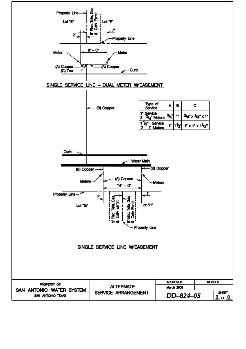
8/21/2019 2014 SAWS Construction Specifications
http://slidepdf.com/reader/full/2014-saws-construction-specifications 131/461

8/21/2019 2014 SAWS Construction Specifications
http://slidepdf.com/reader/full/2014-saws-construction-specifications 132/461
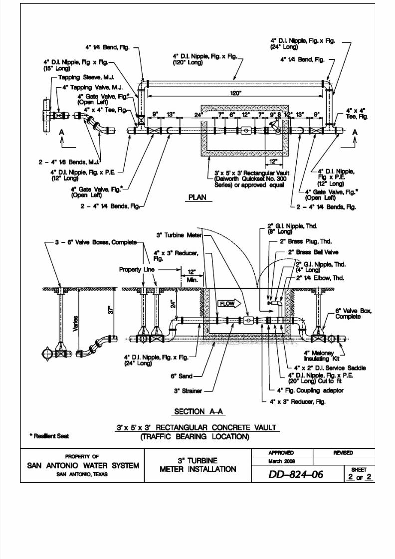
8/21/2019 2014 SAWS Construction Specifications
http://slidepdf.com/reader/full/2014-saws-construction-specifications 133/461

8/21/2019 2014 SAWS Construction Specifications
http://slidepdf.com/reader/full/2014-saws-construction-specifications 134/461

8/21/2019 2014 SAWS Construction Specifications
http://slidepdf.com/reader/full/2014-saws-construction-specifications 135/461

8/21/2019 2014 SAWS Construction Specifications
http://slidepdf.com/reader/full/2014-saws-construction-specifications 136/461

8/21/2019 2014 SAWS Construction Specifications
http://slidepdf.com/reader/full/2014-saws-construction-specifications 137/461

8/21/2019 2014 SAWS Construction Specifications
http://slidepdf.com/reader/full/2014-saws-construction-specifications 138/461

8/21/2019 2014 SAWS Construction Specifications
http://slidepdf.com/reader/full/2014-saws-construction-specifications 139/461

8/21/2019 2014 SAWS Construction Specifications
http://slidepdf.com/reader/full/2014-saws-construction-specifications 140/461

8/21/2019 2014 SAWS Construction Specifications
http://slidepdf.com/reader/full/2014-saws-construction-specifications 141/461

8/21/2019 2014 SAWS Construction Specifications
http://slidepdf.com/reader/full/2014-saws-construction-specifications 142/461

8/21/2019 2014 SAWS Construction Specifications
http://slidepdf.com/reader/full/2014-saws-construction-specifications 143/461

8/21/2019 2014 SAWS Construction Specifications
http://slidepdf.com/reader/full/2014-saws-construction-specifications 144/461
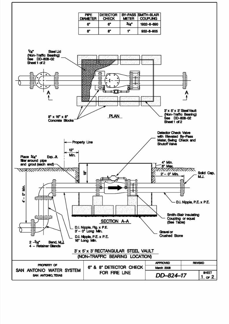
8/21/2019 2014 SAWS Construction Specifications
http://slidepdf.com/reader/full/2014-saws-construction-specifications 145/461

8/21/2019 2014 SAWS Construction Specifications
http://slidepdf.com/reader/full/2014-saws-construction-specifications 146/461

8/21/2019 2014 SAWS Construction Specifications
http://slidepdf.com/reader/full/2014-saws-construction-specifications 147/461

8/21/2019 2014 SAWS Construction Specifications
http://slidepdf.com/reader/full/2014-saws-construction-specifications 148/461

8/21/2019 2014 SAWS Construction Specifications
http://slidepdf.com/reader/full/2014-saws-construction-specifications 149/461

8/21/2019 2014 SAWS Construction Specifications
http://slidepdf.com/reader/full/2014-saws-construction-specifications 150/461

8/21/2019 2014 SAWS Construction Specifications
http://slidepdf.com/reader/full/2014-saws-construction-specifications 151/461

8/21/2019 2014 SAWS Construction Specifications
http://slidepdf.com/reader/full/2014-saws-construction-specifications 152/461

8/21/2019 2014 SAWS Construction Specifications
http://slidepdf.com/reader/full/2014-saws-construction-specifications 153/461
San Antonio Water System Standard Specif ications for Construction
826-1 April 2014
ITEM NO. 826
VALVE BOX ADJUSTMENTS
826.1 DESCRIPTION: This Item shall consist with the adjusting of existing valve boxes in accordance with these specifications and as directed by the Engineer.
826.2 MATERIALS: The materials for valve boxes shall conform to the specifications
contained within the latest revision of SAWS Material Specification Item No. 10-20, "Valve Boxes."
1. Construction Method: The valve box shall be placed in such a manner to
prevent shock or stress from being transmitted to the valve. It shall becentered and plumb over the operating nut of the valve with the box cover
flush with the surface of the finished pavement or at such other level as
may be directed by the Inspector. Valve boxes located in streets or otherarea subject to vehicular traffic shall be provided with concrete collars asshown in the DD-828 Standard Drawing Series. Collars around such
valve boxes shall be formed and finished off neatly and in a workmanlike
manner.
Valve box shall be located so that the valve operating nut is readily
accessible for operation through the opening in the valve box. The valve
box shall be set flush with the surface of the finished pavement or at suchother elevations as may be specified. Pits shall be constructed so that it
permits minor valve repairs and provides the valve and pipe protection
from impact where they pass through the pit walls.
2. Existing valve box: Existing valve boxes shall be defined as boxes which
are located within the right-of-way of the specified area of construction
operations and are in conflict. These boxes shall be adjusted to match proposed finished grades.
Valve boxes installed as part of a new valve and mainline construction
project are considered "new valves." Adjustments to “new valves” areincidental to the installation of the valve and are paid for as part of Item
Nos. 828, 830 or 832 of these specifications. Separate pay shall not be
given to adjust "new valves" to finished grade.
826.3 MEASUREMENT: Adjustment of valve boxes will be measured by the unit ofvalve boxes adjusted to the finished grade.

8/21/2019 2014 SAWS Construction Specifications
http://slidepdf.com/reader/full/2014-saws-construction-specifications 154/461
San Antonio Water System Standard Specif ications for Construction
826-2 April 2014
826.4 PAYMENT: Payment for "Valve Box Adjustment" shall be made at the contract
unit price.
- End of Specification -

8/21/2019 2014 SAWS Construction Specifications
http://slidepdf.com/reader/full/2014-saws-construction-specifications 155/461
San Antonio Water System Standard Specif ications for Construction
828-1 April 2014
ITEM NO. 828
GATE VALVES
828.1 DESCRIPTION: This item shall consist of gate valves installed in accordancewith these specifications and as directed by the Engineer.
828.2 SUBMITTALS: Contractor shall submit manufacturer's product data,
instructions, recommendations, shop drawings, and certifications.
828.3 MATERIALS: The materials for all gate valves shall conform to the
specifications contained within the latest revision of SAWS Material
Specification Item No. 21-02, "Resilient Seated Gate Valves and TappingValves."
828.4 CONSTRUCTION: Gate valve installation shall include: valve, reaction blocking (conforming to Standard Drawing DD-828-1), cast iron boot, valve box
extension (having ductile iron riser pipe), valve box, concrete collar (where
subjected to vehicular traffic), and valve box lid. Gate valves constructed in theterrace shall be constructed with No. 3 bars all around.
The valve box shall be placed in such a manner to prevent shock or stress being
transmitted to the valve. All valves located 6 feet and deeper shall include valvekey extensions inside the valve box. The Contractor has the option to install fully
adjustable valve box and valve key extension systems, on all valves located
between 6 feet and 13 feet. Adjustable valve box and valve key extensionsystems shall be centered over the valve’s operating nut with the box cover flush
with the finished pavement surface or located at another level as directed by the
Engineer. Valve boxes located in streets or other area subject to vehicular traffic
shall be provided with concrete collars as shown in these standard drawings.Collars around such valve boxes shall be formed and finished off neatly and in a
sound workmanlike manner.
Valve pits shall be located so that the valve operating nut is readily accessible for
operation through the opening in the valve box. The valve box shall be set flush
with the finished pavement surface or at other finish elevations as may be
specified. Pits shall be constructed in such a manner to permit minor valve
repairs and provide protection to the valve and pipe from impact (where penetrating through pit walls).
In Pressure Zones 9-16, all valves 6 inches and larger shall be supported on a
concrete pad in accordance with Standard Drawings DD-828-2 and DD-828-3.
828.5 MEASUREMENT: Gate valves and valve boxes will be measured by the unit of

8/21/2019 2014 SAWS Construction Specifications
http://slidepdf.com/reader/full/2014-saws-construction-specifications 156/461
San Antonio Water System Standard Specif ications for Construction
828-2 April 2014
each such assembly of the various sizes of gate valves and valve boxes installed to
the finished grade.
828.6 PAYMENT: Payment for gate valves, complete with valve box, will be made atthe unit price bid for each assembly of the various sizes of gate valves and valve
boxes installed. Payment shall also include: excavation, selected embedment
material, anti-corrosion embedment, hauling, and disposition of excavated surplusmaterial, backfill, concrete collar at the valve box (where subjected to vehicular
traffic), riser pipe, cast iron boot, packing, tar paper, concrete grout, concrete
reaction blocking, protective coating material for bolts, nuts, and ferrous surfaces,and polyethylene sleeve.
- End of Specification -

8/21/2019 2014 SAWS Construction Specifications
http://slidepdf.com/reader/full/2014-saws-construction-specifications 157/461

8/21/2019 2014 SAWS Construction Specifications
http://slidepdf.com/reader/full/2014-saws-construction-specifications 158/461
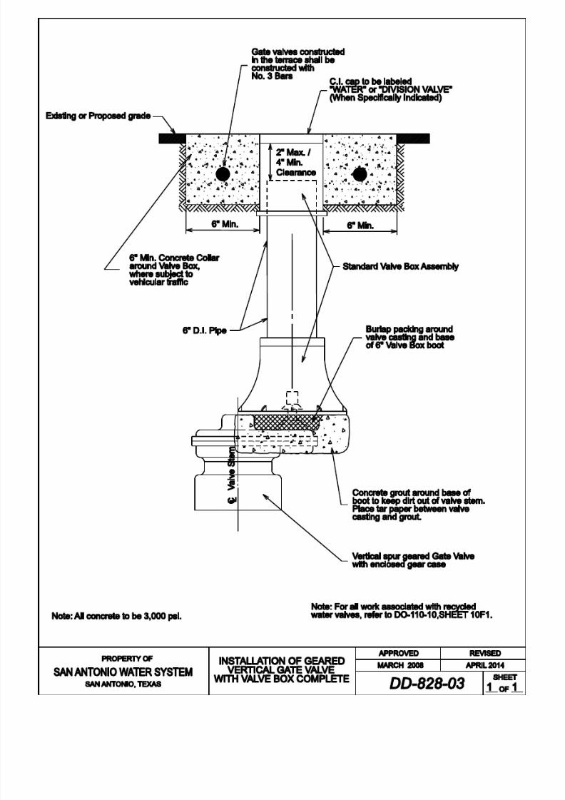
8/21/2019 2014 SAWS Construction Specifications
http://slidepdf.com/reader/full/2014-saws-construction-specifications 159/461

8/21/2019 2014 SAWS Construction Specifications
http://slidepdf.com/reader/full/2014-saws-construction-specifications 160/461

8/21/2019 2014 SAWS Construction Specifications
http://slidepdf.com/reader/full/2014-saws-construction-specifications 161/461
San Antonio Water System Standard Specif ications for Construction
830-1 April 2014
ITEM NO. 830 BUTTERFLY VALVES
830.1 DESCRIPTION: This item shall consist of butterfly valves installed inaccordance with these specifications and as directed by the Engineer.
830.2 SUBMITTALS: Contractor shall submit manufacturer's product data,
instructions, recommendations, shop drawings, and certifications.
830.3 MATERIALS: The materials for all butterfly valves shall conform to the
specifications contained within the latest revision of SAWS' Material
Specification Item No. 21-05 "Hand - Operated Butterfly Valves," and "Rubber-
Seated Butterfly Valves 3 inches Through 72 inches.".
830.4 CONSTRUCTION: Butterfly valve installation shall include; butterfly valve,coated and wrapped steel pipe nipple with reaction stop ring, concrete reaction
blocking, cast-iron boot, valve box extension (ductile iron riser pipe), valve boxand lid, concrete collar (where subjected to vehicular traffic), all couplings and all
coupling adapters required to complete the connection. The entire valve, except
for the operating nut, shall be coated with an approved SAWS sewer structuralcoating, and wrapped with Polywrap. Butterfly valves installed in the terrace
shall be constructed with No. 3 bars all around.
The valve box shall be placed in such a manner to prevent shock or stress beingtransmitted to the valve. All valves located 6 feet and deeper shall include valve
key extensions inside the valve box. The Contractor has the option to install fullyadjustable valve box and valve key extension systems on all valves located between 6 feet and 13 feet. Adjustable valve box and valve key extension
systems shall be centered over the valve’s operating nut with the box cover flush
with the finished pavement surface or located at another level as directed by theEngineer. Valve boxes located in streets or other areas subject to vehicular traffic
shall be provided with concrete collars as shown in the DD-830 Standard Drawing
Series. Collars around such valve boxes shall be formed and finished off neatly
and in a sound workmanlike manner.
830.5 MEASUREMENT: Butterfly valves and boxes will be measured by the unit of
each such assembly of the various sizes of butterfly valves and boxes approvedand installed.
830.6 PAYMENT: Payment for butterfly valves, complete with box, will be made at
the unit price bid for each assembly of the various types and sizes of valves andvalve boxes installed. Payment shall also include: excavation, selected

8/21/2019 2014 SAWS Construction Specifications
http://slidepdf.com/reader/full/2014-saws-construction-specifications 162/461
San Antonio Water System Standard Specif ications for Construction
830-2 April 2014
embedment material, anti-corrosion embedment, hauling, and disposition ofexcavated surplus material, backfill, concrete collar at the valve box (where
subjected to vehicular traffic), ductile iron riser pipe, cast iron boot, packing, tar
paper, concrete grout, concrete reaction blocking, protective coating material for bolts, nuts, and ferrous surfaces, and polyethylene sleeve. For butterfly valves
only, in addition to the above, such payment shall also include mechanical and
transition couplings, coated and wrapped steel pipe and nipples required tocomplete the connection.
- End of Specification -

8/21/2019 2014 SAWS Construction Specifications
http://slidepdf.com/reader/full/2014-saws-construction-specifications 163/461

8/21/2019 2014 SAWS Construction Specifications
http://slidepdf.com/reader/full/2014-saws-construction-specifications 164/461

8/21/2019 2014 SAWS Construction Specifications
http://slidepdf.com/reader/full/2014-saws-construction-specifications 165/461
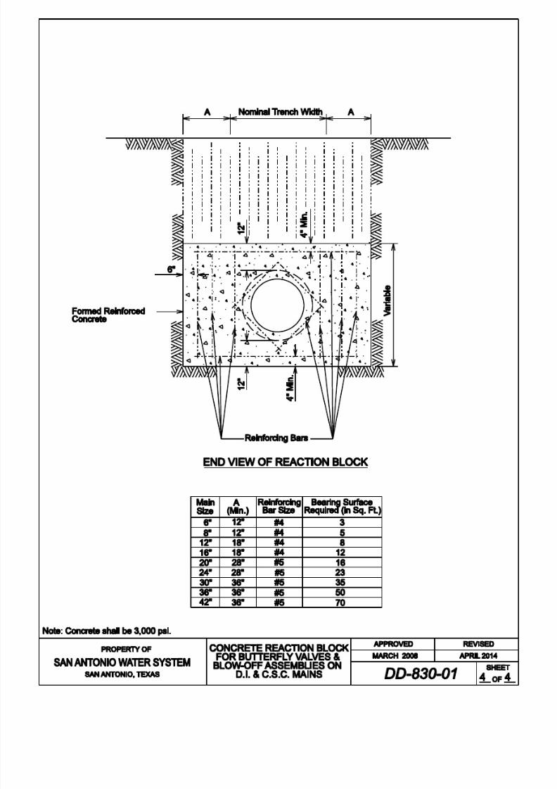
8/21/2019 2014 SAWS Construction Specifications
http://slidepdf.com/reader/full/2014-saws-construction-specifications 166/461

8/21/2019 2014 SAWS Construction Specifications
http://slidepdf.com/reader/full/2014-saws-construction-specifications 167/461
PROPERTY OF
S N NTONIO W TER SYSTEM
SAN ANTONIO, TEXAS
APPRO VED REV ISED
APRIL 2014ARCH 2008
SHEET
OF
MEGA LUG
MEGA LUG
EGA LUG
M.J. Solid Long Sleeve
Butterfly Valve - Flanged
FXP.E. Nipple D.I.
1 Gap
MEGA LUG
M.J. Solid Long Sleeve
M.J. Solid Long Sleeve
Suppor t
1 Gap
FXP.E. Nipple D.I.
PV C
or
D.I.
PV C
or
D.I.
BUTTERFLY VALVE
ASSEMBLY ON
PVC OR D I PIPE
N.T.S

8/21/2019 2014 SAWS Construction Specifications
http://slidepdf.com/reader/full/2014-saws-construction-specifications 168/461
San Antonio Water System Standard Specif ications for Construction
831-1 April 2014
ITEM NO. 831 CUT-IN TEE
831.1 DESCRIPTION: This item shall consist of cut-in tees (various types and sizes)installed in accordance with these specifications and as directed by the Engineer.
831.2 SUBMITTALS: Contractor shall submit manufacturer's product data,
instructions, recommendations, shop drawings, and certifications.
831.3 MATERIALS: The materials for cut-in tees shall conform to the specifications
contained within the latest revision of SAWS’ Material Specification for all
appropriate items.
831.4 CONSTRUCTION: The work involved in cutting in a tee shall consist of the
following: excavation, shutdown and isolation of existing main to which the newmain is to be connected, cutting pipe for the connection, dewatering theexcavation, customer notification of service interruption where required,
installation of all pipe used to complete the connection, all necessary tie-ins
(connections to existing or new main), fittings, approved reaction blockingrequired and backfilling the excavation with approved selected materials or
flowable backfill, if required. Where the installation of a valve is required,
payment will be made in accordance with, Item No. 828, “Gate Valves.”
The processes associated with disturbing and restoring pavements (any type),
curbs, sidewalks, backfilling to final grade, flowable backfill (if required) and
sodding for the installation of a cut-in tee will be considered subsidiary to thework and must comply with the applicable TxDOT Specification or City of San
Antonio Specifications for Public Works Construction, any other governing
entity’s specifications, and applicable street cut policies, ordinances, or permits.
831.5 MEASUREMENT: Cut-in tees will be measured by the unit of each such
assembly of the various sizes of tee installed.
831.6 PAYMENT: Payment for cut-in tees will be made at the unit price bid for each
assembly of the various types and sizes of tees to be installed. Such payment
shall also include; all necessary tie-ins, protective coating materials for bolts, nuts,
ferrous surfaces, polyethylene sleeve, where required, and any necessary haulingand disposition of surplus excavated materials.
- End of Specification -

8/21/2019 2014 SAWS Construction Specifications
http://slidepdf.com/reader/full/2014-saws-construction-specifications 169/461
San Antonio Water System Standard Specif ications for Construction
832-1 April 2014
ITEM NO. 832
TAPPING SLEEVES AND VALVES
832.1 DESCRIPTION: This item shall consist of tapping sleeves and valves installed
in accordance with these specifications and as directed by the Engineer. The useof size on size taps shall not be permitted. Only cut-in tees shall be used withinthe system, unless otherwise approved.
832.2 SUBMITTALS: Contractor shall submit manufacturer's product data,instructions, recommendations, shop drawings, and certifications.
832.3 MATERIALS: The materials for tapping sleeves and valves shall conform to the
specifications contained within the latest revision of SAWS' MaterialSpecification Item Nos. 100-35, "Tapping Sleeves," and 21-02, "Resilient Seated
Gate Valves and Tapping Valves."
832.4 CONSTRUCTION: The installation work involved in tapping sleeves and valvesshall consist of: excavation, backfilling the excavation with approved selected
material, tapping sleeve, approved reaction blocking conforming to Standard
Drawing DD-839, tapping valve, valve box assembly, concrete collar (wheresubjected to street traffic), and cast iron lid. New taps will not be permitted closer
than 2 feet of a joint or existing tap. The use of a shell-type cutter shall be
required when tapping sleeves and valves. Whenever working on potable or
recycle water systems, the shell cutter shall be disinfected with bleach prior to thestart of work. The cutting edge shall be sharp and round. Any defective cutters
shall be rejected by the Inspector.
All the tapping sleeves shall be air tested to 50 psi prior to tapping the main line.
The valve box shall be placed in such a manner to prevent shock or stress from being transmitted to the valve. Valve boxes shall be centered over the valve’s
operating nut with the box cover flush with the finished pavement surface or
located at another level as directed by the Inspector. Valve boxes located instreets or other areas subject to vehicular traffic shall be provided with concrete
collars as shown in the accompanying standard drawings. Collars around such
valve boxes shall be formed and finished off neatly and in a sound workmanlike
manner.
832.5 MEASUREMENT: Tapping Sleeves, Valves, and Boxes will be measured by theunit of each such assembly of the various sizes of tapping sleeves, valves and
boxes approved and installed.
832.6 PAYMENT: Payment for Tapping Sleeves and Valves, complete with boxes, will
be made at the unit price bid for each such assembly of the various types and sizesof valves and valve boxes installed and approved. Such payment shall also
include: excavation, selected embedment material, anti-corrosion embedment

8/21/2019 2014 SAWS Construction Specifications
http://slidepdf.com/reader/full/2014-saws-construction-specifications 170/461
San Antonio Water System Standard Specif ications for Construction
832-2 April 2014
when specified, hauling, and disposition of surplus excavated material, backfill,concrete collar at the valve box where subjected to vehicular traffic, ductile iron
riser pipe, cast iron boot, packing, tar paper, concrete grout, concrete reaction
blocking, protective coating material for bolts, nuts, and ferrous surfaces, and
polyethylene sleeve, where required.
- End of Specification -

8/21/2019 2014 SAWS Construction Specifications
http://slidepdf.com/reader/full/2014-saws-construction-specifications 171/461
San Antonio Water System Standard Specif ications for Construction
833-1 April 2014
ITEM NO. 833 METER AND METER BOX INSTALLATION
833.1 DESCRIPTION: This item shall consist of meter and meter box installation and
adjustment installed in accordance with these specifications and as directed by theEngineer.
833.2 SUBMITTALS: Contractor shall submit manufacturer's product data,
instructions, recommendations, shop drawings, and certifications.
833.3 MATERIALS: The materials for meter and meter box installation and adjustment
shall conform to the specifications contained within the latest revision of SAWS'
Material Specification Item No. 10-30, "Meter Boxes."
833.4 CONSTRUCTION:
1. Physical movement of existing meters and meter boxes to new locations
may be required where service lines are transferred to new mains in
conjunction with main replacement work. Unless specified otherwise, theContractor shall move existing meters and meter boxes and reconnect and
adjust customer's yard piping as part of transferring service lines. A
dielectric coupling (PVC schedule 80) shall be installed within the meter
box between the meter and the customer's yard piping.
Round and oval meter boxes with round covers shall be salvaged and
returned to the Owner by the Contractor. The Contractor shall alsoreplace the salvaged meter boxes with the new, appropriately styled oval
plastic meter box with oval cover, or rectangular meter box. Unless
otherwise specified, the old service line shall be abandoned after the
existing meter has been reset in the existing or new meter box.
Where meter boxes are installed in sidewalks or driveways, the Contractor
shall install a number one meter box (2 pieces) as shown in the MaterialSpecifications Item No. 10-30 and theDD-833 Standard Drawing Series.
New meters will be set by the Owner where mains are extended and newservices lines are installed for new or initial customer service. In lieu of
the new meter, the Contractor shall furnish and install a meter template in
accordance with the DD-833 Standard Drawing Series. Contractor shall
make a 1 inch diagonal cut thru the wall of the template.
Meter and meter box configuration, shall have the meter set horizontal,
approximately 6 inches below the top of meter box, so that the meter is
above the bottom of the meter box and in-line with the meter box lidopening. The top of the meter box shall be flush with the existing ground

8/21/2019 2014 SAWS Construction Specifications
http://slidepdf.com/reader/full/2014-saws-construction-specifications 172/461
San Antonio Water System Standard Specif ications for Construction
833-2 April 2014
surface. All excess soil above the meter coupling, meter flange and meternuts inside the meter box shall be removed so that the meter register is
clearly visible. The Contractor shall exercise special precautions during
excavation at the existing meter location in order to minimize thedisturbance of the customer's yard piping. However, if the existing meter
elevation is low, the Contractor shall raise the existing meter to conform tothe correct configuration indicated herein. Adjustment of meter to propergrade is incidental to the construction and will not be paid for separately.
Where required, pressure reducing valves shall be installed by the
customer in accordance with the Uniform Plumbing Code and shall be placed beyond the outlet side of the meter, but not within the Owner's
meter box. The pressure reducing valve shall be the property of the water
user who will be responsible for its installation, maintenance, and
replacement, as required.
2. The meter box adjustment shall not exceed 10 linear feet from the existing box.
833.5 MEASUREMENT: Relocation of meters and boxes will be measured by the unit
of the various types and sizes of meters and boxes relocated.
833.6 PAYMENT: Payment for "Existing Meter and Existing Meter Box Relocation (⅝inch through 2 inch meter)" will be made at the unit price bid for each existing
meter and existing meter box relocated. Such payment shall also include;excavation, hauling and disposition of surplus materials, sand backfill, removal
and replacement of yard piping with copper tubing of the various types and sizes
and in the quantities necessary to complete the connection and adjustment between the relocated existing meter and existing meter box, and the existing yard
piping.
Payment for "Existing Meter and New Meter Box Relocation (⅝ inch through 2inch meter)" will be made at the unit price bid for each existing meter relocated to
a new meter box. Such payment shall also include excavation, hauling and
disposition of surplus materials, sand backfill, removal and replacement ofwhatever type surface structure encountered, salvaging the existing meter box,
reconnection and adjustment of yard piping with copper tubing of the various
types and sizes and in the quantities necessary to complete the connection
between the relocated existing meter and new meter box, and the existing yard piping.
Payment for number one meter box installation in sidewalks and driveways shall be paid in the amount of difference between the standard meter box and the
number one box.

8/21/2019 2014 SAWS Construction Specifications
http://slidepdf.com/reader/full/2014-saws-construction-specifications 173/461
San Antonio Water System Standard Specif ications for Construction
833-3 April 2014
- End of Specification -

8/21/2019 2014 SAWS Construction Specifications
http://slidepdf.com/reader/full/2014-saws-construction-specifications 174/461

8/21/2019 2014 SAWS Construction Specifications
http://slidepdf.com/reader/full/2014-saws-construction-specifications 175/461

8/21/2019 2014 SAWS Construction Specifications
http://slidepdf.com/reader/full/2014-saws-construction-specifications 176/461
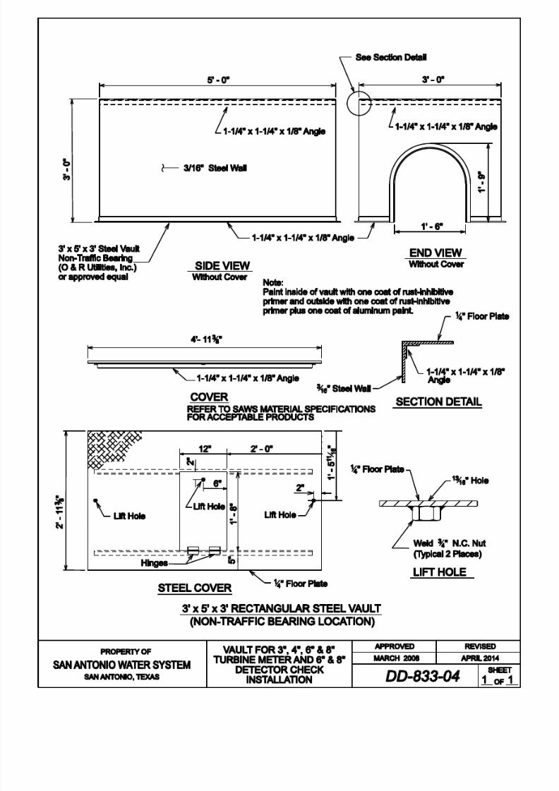
8/21/2019 2014 SAWS Construction Specifications
http://slidepdf.com/reader/full/2014-saws-construction-specifications 177/461
8/21/2019 2014 SAWS Construction Specifications
http://slidepdf.com/reader/full/2014-saws-construction-specifications 178/461
San Antonio Water System Standard Specif ications for Construction
834-1 April 2014
ITEM NO. 834
FIRE HYDRANTS
834.1 DESCRIPTION: This item shall consist of fire hydrant installations using jointrestraints in accordance with these specifications and as directed by the Engineerwith the contract documents.
834.2 MATERIALS: The materials for fire hydrant installations shall conform to thespecifications contained within the latest revision of SAWS’ Material
Specification Item No. 95-10, “Specifications of Pipe Joint Restraint Systems,”
Item No. 95-10, Item No. 113-02, "Ductile Iron Restrained Joint Fittings for Use
on Ductile Iron and Polyvinyl Chloride Pipe," and Item No. 21-30, “FireHydrants.”
834.3 CONSTRUCTION:
1. General: Hydrants shall be connected to mains as shown in the contract
documents or as directed by the Engineer. They shall be installed in
accordance with Standard Drawings DD-834-01, DD-834-02, and DD-834-03. Hydrants shall also be installed in a location where there is
accessibility and in a safe location where there is a minimum possibility of
damage from vehicles or injury to pedestrians. In situations where
hydrants are placed directly behind curbs, hydrant barrels shall be set sothat no portion of the hydrant will be less than 12 inches nor more than 7
feet from the back of the curb. Where hydrants are set in the lawn spaces
between the curb and the sidewalk or between the sidewalk and the property line, no portion of the hydrant or nozzle cap shall be within 6
inches of the sidewalk.
Setting final grade of fire hydrants to match proposed or existing fieldconditions is the responsibility of Contractor.
Hydrants shall be set in accordance with Standard Drawings DD-834-01,DD-834-02, and DD-834-03and shall be set plumb and shall have their
nozzles parallel with, or at right angles to, the curb with the pumper nozzle
facing the curb. Drainage and concrete pads shall be provided at the base
of hydrants as specified. No fire hydrant drainage system or pit shall beconnected to a storm or sanitary sewer.
The Contractor shall install anchored or flanged style fittings inaccordance with Standard Drawings DD-834-01, DD-834-02, and DD-
834-03.

8/21/2019 2014 SAWS Construction Specifications
http://slidepdf.com/reader/full/2014-saws-construction-specifications 179/461
San Antonio Water System Standard Specif ications for Construction
834-2 April 2014
2. Restrained Joints: Restrained mechanical joints that require field welding
or groove cuts into the pipe barrel for restraint will not be accepted.
Restrained joints shall be furnished for pipe at all changes in direction asindicated in the contract documents, or as directed by the Engineer.
Restrained mechanical joints shall be locked mechanical joints. All joints
shall conform to the San Antonio Water System Material SpecificationItem No. 95-10, “Pipe Joint Restraint Systems.” The restraint system shall
be capable of a test pressure twice the maximum sustained working
pressure of 350 psi for ductile iron and PVC pipe.
3. Replacing and Relocating Existing Fire Hydrants: When existing fire
hydrants are to be replaced or relocated, the work shall be accomplished
by either of the following:
a. Cutting or installing a tee of the size and type as indicated in the
contract documents or as directed by the Engineer.
b. Using a tapping sleeve and valve of the size and type as indicated
in the contract documents to install a new fire hydrant to an
existing or new water main. Size on size taps will not be permitted.
c. Relocating the existing fire hydrant by closing the existing firehydrant branch valve, removing the existing fire hydrant,
extending the fire hydrant branch and installing the existing firehydrant as specified herein.
The Contractor shall salvage the existing fire hydrants and other materials
as designated in the field by the Inspector and shall deliver this material to
the SAWS materials storage yard, located at 3930 East Houston Street.Fire hydrant branches shall be abandoned by cutting and capping the fire
hydrant cast iron tee at the service main and the surface restored to its
original condition.
After a fire hydrant has been set, hydrants shall be painted with a suitable
primer and finished with oil-based aluminum paint from the top of thehydrant to a point 18-20 inches below the center line of the pumper nozzleand applied to all exposed metal surfaces above the hydrant base flange.
The payment for fire hydrant painting shall be included in the unit cost for
installing the fire hydrant.

8/21/2019 2014 SAWS Construction Specifications
http://slidepdf.com/reader/full/2014-saws-construction-specifications 180/461
San Antonio Water System Standard Specif ications for Construction
834-3 April 2014
4. Installation on Water Mains: Ductile iron pipe, cast iron and ductile iron
fittings, and valves used in the placement of fire hydrants and connections
to the main will be considered part of the fire hydrant installation and not a
part of the main construction. No separate payment will be made for this pipe. Hydrants shall be connected to the mains as shown in the contract
documents or as directed by the Engineer. Hydrants shall also be installed
in a location where there is accessibility and in a safe location where thereis a minimum possibility of damage from vehicles or injury to pedestrians.
834.4 MEASUREMENT: Standard Fire Hydrants with 6 inch Valve and Box will bemeasured by the unit of each fire hydrant, valve, and box installed. Relocate Fire
Hydrants will be measured by the unit of each fire hydrant relocated.
Standard Fire Hydrants with Tapping Sleeve, 6 inch Valve, and Box will be
measured by the unit of each fire hydrant, including the various sizes of tappingsleeves, valves and boxes installed.
834.5 PAYMENT: Payment included in following bid pay items shall include:
excavation, backfill, selected material, anti corrosion embedment when specified,
hauling and disposition of surplus excavated materials, backfill, branch line pipe,
nipples, and fittings exclusive of the tee from the main line pipe, polyethylenesleeve where required, asphalted material for ferrous surfaces, joint restraints,
concrete pad, restoration of existing fire hydrant sites and removal and relocation
of existing fire hydrant as specified.
PAY ITEM No. 834.1 – Fire Hydrant: Installation of a new fire hydrant asspecified in the contract documents and as specified herein for a fire hydrant with
6 inch valve and box.
PAY ITEM No. 834.2 – Tapped Fire Hydrant: Payment for installation of a new
fire hydrant by tapping an existing or new water main as specified in the contractdocuments and as specified herein for a Fire Hydrant with tapping sleeve, 6 inch
valve and box.
PAY ITEM No. 834.3 – Relocate Fire Hydrant: Payment for Relocate Fire
Hydrant shall include relocating an existing fire hydrant to a new location as
specified in the contract documents and as specified herein. Restoration of theexisting fire hydrant site shall be inclusive to this line item.
- End of Specification -

8/21/2019 2014 SAWS Construction Specifications
http://slidepdf.com/reader/full/2014-saws-construction-specifications 181/461

8/21/2019 2014 SAWS Construction Specifications
http://slidepdf.com/reader/full/2014-saws-construction-specifications 182/461

8/21/2019 2014 SAWS Construction Specifications
http://slidepdf.com/reader/full/2014-saws-construction-specifications 183/461

8/21/2019 2014 SAWS Construction Specifications
http://slidepdf.com/reader/full/2014-saws-construction-specifications 184/461

8/21/2019 2014 SAWS Construction Specifications
http://slidepdf.com/reader/full/2014-saws-construction-specifications 185/461

8/21/2019 2014 SAWS Construction Specifications
http://slidepdf.com/reader/full/2014-saws-construction-specifications 186/461
San Antonio Water System Standard Specif ications for Construction
836-1 April 2014
ITEM NO. 836 GREY-IRON AND DUCTILE-IRON FITTINGS
836.1 DESCRIPTION: This item shall consist of grey-iron and ductile-iron fittings
installation and adjustment installed in accordance with these specifications and
as directed by the Engineer.
836.2 SUBMITTALS: Contractor shall submit manufacturer's product data,
instructions, recommendations, shop drawings, and necessary certifications.
836.3 MATERIALS: The materials for grey-iron and ductile-iron fittings installationshall conform to the latest provisions of American National Standard for Ductile-
Iron (ANSI)/ American Water Works Association (AWWA) C153/A21.53,
Compact Fittings 3-inch through 64-inch and ANSI/AWWA C110/A21.10, FullBody Fittings 3-inch through 48-inch for Water Service or most applicable
approved equal provisions, and the specifications contained within the latest
revision of SAWS’ Material Specification Item No. 10-10, "Grey-Iron andDuctile-Iron Fittings."
836.4 CONSTRUCTION: All fittings shall be either restrained mechanical joint
compact or flanged joint, unless otherwise specified in the contract documents.All mechanical joint compact fittings shall be installed using approved restraining
glands in accordance with SAWS' Material Specification Item No. 113-02. No
separate payment will be made for these restraining glands. Approved adaptersshall be used where necessary to provide a transition between pipes and/or fittings
of differing outside diameters. Thrust blocking shall only be utilized, in addition
to restraining glands, if specified in the contract documents, when tying into
existing non-restrained pipe, or when approved by the Inspector. Anti-corrosion protection consisting of polyethylene sleeve and asphaltic material for ferrous
surfaces shall be applied to exterior surfaces of all fittings installed. Anti-
corrosion embedment shall be provided as specified in Item No. 804,"Excavation, Trenching and Backfill."
836.5 MEASUREMENT: Ductile-Iron and Grey-Iron Fittings will be measured by
their weight as listed in Table 836-1 of this specification of the various sizes offittings installed.

8/21/2019 2014 SAWS Construction Specifications
http://slidepdf.com/reader/full/2014-saws-construction-specifications 187/461
San Antonio Water System Standard Specif ications for Construction
836-2 April 2014
836.6 PAYMENT: Payment for Grey-Iron and Ductile-Iron Fittings shall be for
Mechanical Joint Compact fittings (AWWA) C153/A21.53 and/or flanged
fittings. Payment will be made at the unit price bid for each ton of fittings to thenearest one-hundredth of a ton of fittings installed. Individual fitting weights
used for payment calculations will be the weights of fittings listed in Table 836-1
of this specification. Weights of glands, bolts, nuts, gaskets (all types) areconsidered subsidiary to the fittings and no separate payment will be made for
their weight. Payment for fitting weights listed in Table 836-1 shall be full
compensation for excavation, installation, anti-corrosion protection, select anti-corrosion embedment material and installation, hauling and disposition of surplus
excavated materials, all glands, bolts, nuts, rubbers, and flange gaskets of
whatever type required, and concrete thrust/reaction blocking, if required. If
fittings other than those listed in Table 836-1 are approved and installed, the
Contractor shall provide quantities and manufacturers unit weights exclusive ofglands, bolts, and rubbers with pay request.
TABLE 836-1
WEIGHTS OF GREY-IRON AND DUCTILE-IRON FITTINGS (LBS.)
BENDS
Size
(Inches)
MJ
Compact
(C153)
MJ
(C110)
FLG
SB
Size
(Inches)
MJ
Compact
(C153)
MJ
(C110)
FLG
SB
1/4 Bend (90 Degrees) 1/8 Bend (45 degrees)
4 25 55 44 4 21 51 36
6 43 86 67 6 35 75 57
8 61 125 115 8 50 110 105
12 119 258 236 12 96 216 196
16 264 454 478 16 200 345 315
20 447 716 878 20 337 555 485
24 602 1105 1085 24 441 777 730
30 979 1740 1755 30 775 1393 1355
36 1501 2507 2135 36 1140 2163 1755
42 2277 3410 3055 42 1652 2955 2600
48 3016 4595 4095 48 2157 4080 3580
BENDS
Size
(Inches)
MJ
Compact
MJ
(C110)
FLG
SB
Size
(Inches)
MJ
Compact
MJ
(C110)
FLG
SB

8/21/2019 2014 SAWS Construction Specifications
http://slidepdf.com/reader/full/2014-saws-construction-specifications 188/461
San Antonio Water System Standard Specif ications for Construction
836-3 April 2014
(C153) (C153)
1/16 Bend (22-1/2 Degrees) 1/32 Bend (11-1/4 degrees)
418 50
35 417 50
40
6 32 75 64 6 30 73 56
8 46 110 90 8 42 109 90
12 85 220 194 12 74 220 193
16 175 354 315 16 153 354 315
20 314 550 505 20 265 553 505
24 414 809 528 24 339 815 760
30 668 1500 1385 30 603 1410 1395
36 963 2182 1790 36 830 2195 1805
42 1354 3020 2665 42 1210 3035 2680
48 1790 4170 3665 48 1523 4190 3695
TABLE 836-1 CONTINUATION
WEIGHTS OF GREY-IRON AND DUCTILE-
IRON FITTINGS (LBS.)
TEES
Size (Inches) Weight
Run BranchMJ
Compact
(C153)
MJ
(C110)
FLGShort
Body
24 6 466 1035 1089
8 487 1047 1060
12 539 1075 1125
16 625 1109 1070
20 729 1504 1510
24 785 1617 1685
30 8 739 1808 -
12 800 1842 1801
16 959 1885 -20 1026 1941 -
24 1228 2496 2475
30 1373 2531 2615
36 24 1548 2710 2255

8/21/2019 2014 SAWS Construction Specifications
http://slidepdf.com/reader/full/2014-saws-construction-specifications 189/461
San Antonio Water System Standard Specif ications for Construction
836-4 April 2014
30 1901 3545 3000
36 2012 3686 3160
42 24 2272 3690 3245
30 2512 4650 4125
36 3048 5119 5360
42 3225 6320 5580
48 24 2934 4995 4385
30 3147 5140 4455
36 4046 6280 5555
42 4249 8130 7195
48 4469 8420 7385
TABLE 836-1 CONTINUATION
WEIGHTS OF GREY-IRON AND DUCTILE-
IRON FITTINGS (LBS.)
TEES
Size (Inches) Weight
Run BranchMJ
Compact
(C153)
MJ
(C110)
FLGShort Body
3 3 26 56 53
4 3 31 76 54
4 33 80 60
6 4 49 114 90
6 60 124 98
8 4 65 163 155
6 76 175 148
8 89 188 179
12 4 99 316 322
6 115 325 297
8 127 339 346
12 162 407 369
16 6 226 563 573
8 240 565 555
12 283 615 59016 326 676 635
20 6 344 750 773
8 371 766 720
12 427 799 816
16 503 975 950
20 566 1068 1005
TABLE 836-1 CONTINUATION
WEIGHTS OF GREY-IRON AND DUCTILE-
IRON FITTINGS (LBS.) CROSSES
Size (Inches) Weight
Run BranchMJ
Compact
(C153)
MJ
(C110)
FLGShort
Body
24 6 566 1025 -
8 578 1085 1045
12 610 1153 1110
16 663 1256 1200
20975 1733
167524 907 1906 1835
30 8 650 1795 -
12 870 1925 1865
16 900 1950 -
20 1220 2060 -
24 1497 2776 2675
30 1808 3188 3075
36 24 1853 2928 2980
30 2580 3965 -
36 2698 4370 4370
42 24 2415 3910 -
30 2920 5040 -
36 3788 5835 -
42 3908 6493 7145

8/21/2019 2014 SAWS Construction Specifications
http://slidepdf.com/reader/full/2014-saws-construction-specifications 190/461
San Antonio Water System Standard Specif ications for Construction
836-5 April 2014
48 24 3435 5210 -
30 4145 5495 -
36 4873 6790 -
42 5465 8815 -
48 5588 9380 -
TABLE 836-1 CONTINUATION
WEIGHTS OF GREY-IRON AND DUCTILE-
IRON FITTINGS (LBS.)
CROSSES
Size (Inches) Weight
Run BranchMJ
Compact
(C153)
MJ
(C110)
FLGShort Body
3 3 34 70 -
4 3 42 90 -
4 46 105 -
6 4 63 140 -
6 74 160 160
8 4 88 185 185
6 97 205 205
8 105 239 234
12 4 114 340 -
6 135 360 360
8 151 382 385
12 199 493 495
16 6 250 590 575
8 270 619 605
12 332 685 -16 409 811 790
20 6 358 760 -
8 379 822 790
12 413 883 860
16 550 1117 1085
20 598 1274 1230

8/21/2019 2014 SAWS Construction Specifications
http://slidepdf.com/reader/full/2014-saws-construction-specifications 191/461
San Antonio Water System Standard Specif ications for Construction
836-6 April 2014
TABLE 836-1 CONTINUATION
WEIGHTS OF GREY-IRON AND DUCTILE-IRON FITTINGS (LBS.)
CAPS PLUGS
Size (Inches)
MJ Compact
(C153)
MJ
(C110)
MJ Compact
(C153)
MJ
(C110)
4 10 17 12 16
6 16 29 19 28
8 24 45 30 46
12 45 82 54 85
16 95 160 97 146
20 141 235 146 218
24 193 346 197 350
30 362 644 381 626
36 627 912 688 884
42 893 1322 1200 1222
48 1076 1737 1550 1597
TABLE 836-1 CONTINUATION
WEIGHTS OF GREY-IRON AND DUCTILE-IRON FITTINGS (LBS.)
SOLID SLEEVES
Size (Inches) WeightMJ Short
Compact (C153)
MJ Long
Compact (C153)
MJ Short
(C110)
MJ Long
(C110)
4 17 21 35 46
6 28 35 45 65
8 38 48 65 86
12 57 77 113 143
16 127 172 192 257
20 201 258 258 359
24 264 337 340 474
30 500 651 690 100536 725 960 947 1374
42 877 1209 1187 1628
48 1406 1516 1472 2033

8/21/2019 2014 SAWS Construction Specifications
http://slidepdf.com/reader/full/2014-saws-construction-specifications 192/461
San Antonio Water System Standard Specif ications for Construction
836-7 April 2014
TABLE 836-1 CONTINUATION
WEIGHTS OF GREY-IRON AND DUCTILE-IRON FITTINGS (LBS.)
CONCENTRIC REDUCERS
Size (Inches) Weight
Large End Small EndMJ Compact
(C153)
MJ
(C110)
6 4 27 59
8 4 38 81
8 6 41 95
12 4 70 136
12 6 69 150
12 8 70 16716 6 134 234
16 8 136 258
16 12 126 310
20 12 213 427
20 16 221 492
24 12 304 562
24 16 315 633
24 20 315 727
30 16 596 1027
30 20 599 1085
30 24 492 1204
36 20 1042 1459
36 24 785 1580
36 30 655 1868
42 24 1356 2060
42 30 1112 2370
42 36 1116 2695
48 30 1722 3005
48 36 1650 337048 42 1429 3750

8/21/2019 2014 SAWS Construction Specifications
http://slidepdf.com/reader/full/2014-saws-construction-specifications 193/461
San Antonio Water System Standard Specif ications for Construction
836-8 April 2014
- End of Specification -
TABLE 836-1 CONTINUATION
WEIGHTS OF GREY-IRON AND DUCTILE-
IRON FITTINGS (LBS.)
2” Tapped Tees and Crosses
Size
(Inches)
Weight
MJ Compact
(C153)
MJ
(C110)
4 24 47
6 36 71
8 54 97
10 69 130
12 87 169
20 - 259
24 - 320
TABLE 836-1 CONTINUATION
WEIGHTS OF GREY-IRON AND DUCTILE-
IRON FITTINGS (LBS.)
OFFSETS
Size
(Inches)
Weight
MJ Compact
(C153)
MJ
(C110)
4 x 6 35 75
4 x 12 55 83
6 x 6 35 110
6 x 12 67 138
6 x 24 96 189
8 x 6 82 164
8 x 12 98 2098 x 24 141 280
12 x 6 121 320
12 x 12 178 420
12 x 24 240 645
20 x 12 - 1025
20 x 24 - 1245

8/21/2019 2014 SAWS Construction Specifications
http://slidepdf.com/reader/full/2014-saws-construction-specifications 194/461
San Antonio Water System Standard Specif ications for Construction
839-1 April 2014
ITEM NO. 839 ANCHORAGE/THRUST BLOCKING AND JOINT RESTRAINT
839.1 DESCRIPTION: This item shall consist of anchorage/thrust blocking installationand adjustment, in accordance with these specifications and as directed by theEngineer. Pipe restraint devices shall be installed according to the lengths
prescribed herein or as noted in the contract documents, whichever is more
restrictive.
839.2 MATERIALS: The materials for anchorage/thrust blocking installation shall
conform to the appropriate specifications contained within the latest revision of
SAWS Material Specifications. Pipe restraint devices shall conform to the latestrevision of SAWS Material Specification Item Nos. 95-10 and 113-02.
839.3 CONSTRUCTION: Suitable anchorage/thrust blocking or joint restraint shall be provided at all of the following main locations: dead ends, plugs, caps, tees,crosses, valves, and bends, in accordance with the Standard Drawings DD-839
Series. All mechanical (joint) restraints shall be bidirectional. Anchor blocks
shall be constructed solidly behind the fitting and symmetrical with the axis ofresultant thrust, except where this is not possible as in the case of gravity
anchorage for vertical bends. Special ties and anchor fittings may be utilized in
conjunction with blocking when shown in the contract documents or as directed
by the Engineer.
All thrust blocking shall be a minimum of 3,000 psi concrete placed between solid
ground and the fitting except as otherwise shown in the contract documents. Thearea of bearing in contact with solid ground shall be that shown in the contract
documents or as directed by the Engineer.
All thrust blocking placed in conjunction with mains and appurtenancesconstructed in Pressure Zones 9 through 16 shall be in accordance with Standard
Drawings DD-839 Series. In all cases, the design of thrust blocking shall be of
sufficient size to withstand an assumed soil lateral load bearing capacity of 3,000 psf, unless specified otherwise in the contract documents. When specifically
requested by the Contractor and approved by the Engineer, the maximum soil
lateral load bearing capacity that will be allowed for the design of thrust blocking
shall be 5,000 psf. When soil lateral load bearing capacities of 4,000 psf or 5,000 psf are recorded for design of thrust blocks, copies of soil tests made for
determining the lateral load bearing capacity of the subject soil shall be submitted
to the Engineer for approval.
The blocking shall be placed so that pipe and fitting joints will be accessible.

8/21/2019 2014 SAWS Construction Specifications
http://slidepdf.com/reader/full/2014-saws-construction-specifications 195/461
San Antonio Water System Standard Specif ications for Construction
839-2 April 2014
Pipe polywrap shall be placed between the pipe or fitting and the concrete.
The reaction block on the unused branch of a fitting shall be poured separately
from the block across the back of the fitting. If they are poured simultaneously, arigid partition shall be placed between the blocks.
Valves 12 inches or larger in size shall be supported on a concrete pad extendingvertically from 12 inches below the bottom of the valve to the lower quarter point
of the hub and laterally from face to face of hubs and transversely from wall to
wall of the trench.
839.4 MEASUREMENT: Anchorage/Thrust Blocking or Joint Restraints are
considered subsidiary to the work and no separate payment will be made to the
Contractor for this work.
839.5 PAYMENT: Anchorage/Thrust Blocking or Joint Restraints are considered
subsidiary to the work and no separate payment will be made to the Contractor forthis work.
- End of Specification -

8/21/2019 2014 SAWS Construction Specifications
http://slidepdf.com/reader/full/2014-saws-construction-specifications 196/461
Sides of t rench
Select Material
Select Material
Concrete blocking required for
all 12 & larger, except in
high pressure distribution system
where blocking is required for
all valves
SAN ANTONIO, TEXAS
PROPERTY OF
SAN ANTONIO WATER SYSTEM
SHEET
OF
THRUST BLOCKS FOR
FITTINGS ( WATER ONLY )
A PPR O V ED REV ISED
M A RCH 2008 A PRIL 2014
Pour base after
Hydrant has been
placed
Hydrant Drain
ELEVATION
PLAN
PLAN
ELEVATION

8/21/2019 2014 SAWS Construction Specifications
http://slidepdf.com/reader/full/2014-saws-construction-specifications 197/461
R.L. = RESTRAINED LENGTHS TO BE
DETERMINED BY DESIGN ENGINEER
APRIL 2014JOINT RESTRAINTS FORFITTINGS (WATER ONLY)

8/21/2019 2014 SAWS Construction Specifications
http://slidepdf.com/reader/full/2014-saws-construction-specifications 198/461

8/21/2019 2014 SAWS Construction Specifications
http://slidepdf.com/reader/full/2014-saws-construction-specifications 199/461

8/21/2019 2014 SAWS Construction Specifications
http://slidepdf.com/reader/full/2014-saws-construction-specifications 200/461

8/21/2019 2014 SAWS Construction Specifications
http://slidepdf.com/reader/full/2014-saws-construction-specifications 201/461

8/21/2019 2014 SAWS Construction Specifications
http://slidepdf.com/reader/full/2014-saws-construction-specifications 202/461

8/21/2019 2014 SAWS Construction Specifications
http://slidepdf.com/reader/full/2014-saws-construction-specifications 203/461

8/21/2019 2014 SAWS Construction Specifications
http://slidepdf.com/reader/full/2014-saws-construction-specifications 204/461

8/21/2019 2014 SAWS Construction Specifications
http://slidepdf.com/reader/full/2014-saws-construction-specifications 205/461

8/21/2019 2014 SAWS Construction Specifications
http://slidepdf.com/reader/full/2014-saws-construction-specifications 206/461
San Antonio Water System Standard Specif ications for Construction
840-1 April 2014
ITEM NO. 840 WATER TIE-INS
840.1 DESCRIPTION: This item shall consist of water main tie-ins installed in
accordance with these specifications and as directed by the Engineer.
840.2 MATERIALS: The materials for water main tie-ins shall conform to the
specifications contained within the latest revision of SAWS’ MaterialSpecifications for all appropriate items.
840.3 CONSTRUCTION: The Contractor shall make tie-ins from new water mains to
existing water mains as shown in the contract documents or as directed by theEngineer. The Contractor shall be responsible for all shutdowns and isolation of
the existing mains; cutting pipe for the connection; dewatering the excavation;
customer notification of the shutdown; and all other requirements as directed bythe Inspector in order to provide completion of this effort in a safe and secure
manner. Work performed by the Contractor on mains 16 inches and larger, will
require operation of any valves by SAWS forces. Therefore ample coordination
beforehand (2 work days) shall be provided by the Contractor for this interactionto occur. All tie-ins shall be done after normal work hours, (8am-5pm). During
construction, the planned shutdown and tie-in work shall be coordinated through
and approved by the Inspector with a minimum of two weeks prior notice of suchactivity and accomplished at a time which will be at the least inconvenience to thecustomers. No additional compensation will be provided for tie-ins accomplished
after normal working hours.
840.4 MEASUREMENT: Tie-ins will be measured by the unit of each such assembly
of the various sizes of tie-ins installed at the proposed main to be accepted.
840.5 PAYMENT: Payment for "Tie-ins" will be made at the unit price bid for each tie-
in of the various types and sizes completed from an existing main to the proposed
main to be accepted. Such payment shall include; shut-down and isolation of the
existing main to which the new main is to be connected, cutting pipe for theconnection, dewatering the excavation, and customer notification of service
interruption where required. Connections between new and existing mains which
are made with tapping sleeves and valves and by cutting-in tees will be processed
as a no separate pay item.
- End of Specification -

8/21/2019 2014 SAWS Construction Specifications
http://slidepdf.com/reader/full/2014-saws-construction-specifications 207/461
San Antonio Water System Standard Specif ications for Construction
841-1 April 2014
ITEM NO. 841 HYDROSTATIC TESTING OPERATIONS
841.1 DESCRIPTION: This item shall consist of hydrostatic testingoperations, of water mains in accordance with these specifications.
841.2 MATERIALS: The materials for hydrostatic testing operations
installation and adjustment shall conform to the appropriate specificationscontained within the latest revision of SAWS’ Material Specifications.
841.3 PROTOCOL:
1. Flushing: Immediately upon completion of water main work, the
Contractor shall flush all mains affected by the scope of the work.
This flushing shall consist of completely filling sections of main between valves and then displacing such initial volumes of water
by introducing clear water from existing facilities into and through
the main to the point of discharge from the main being flushed.The flow-through shall continue until it is determined all dust,
debris, or foreign matter that may have entered during pipe laying
operations has been flushed out. All new mains shall then be left
under system pressure for testing.
To avoid damage to pavement and inconvenience to the public, fire
hoses shall be used to direct flushing water from the main intosuitable drainage channels or sewers. The contractor is to
coordinate with the Inspector prior to flushing.
2. Operation of Valves: No valve in the Owner's water distributionsystem shall be operated by the Contractor without prior
permission of the Inspector. The Contractor shall notify the
Inspector when a valve is to be operated and shall only operate thevalve in the presence of the Inspector.
3. Hydrostatic Test: Except in the high pressure sections of the water
distribution system (Pressure Zones 9-16) where test pressures will
exceed 150 psi, all new mains shall be hydrostatically field testedat a maximum test pressure of 150 psi before acceptance by the
Engineer or Inspector. Where designated as "High Pressure Area,"
all new mains shall be hydrostatically field tested at a maximumtest pressure of 200 psi before acceptance by the Engineer or
Inspector. It is the intent of these Specifications that all joints be

8/21/2019 2014 SAWS Construction Specifications
http://slidepdf.com/reader/full/2014-saws-construction-specifications 208/461
San Antonio Water System Standard Specif ications for Construction
841-2 April 2014
watertight and that all joints which are found to leak byobservation during any test shall be made watertight by the
Contractor. When repairs are required, the hydrostatic field test
shall be repeated until the pipe installation conforms to the
specified requirements and is acceptable to the Engineer/Inspector.The Contractor shall insure that the Engineer/Inspector be present
for the duration of the pressure test.
4. Test Procedures: After the new main has been laid and backfilled
as specified (but prior to chlorination and replacement of pavement), it shall be filled with water for a minimum of 24 hours
and then subjected to a hydrostatic pressure test.
The specified test pressure shall be supplied by means of a pumpconnected to the main in a satisfactory manner. The pump, pipe
connection, and all necessary appurtenances including gauges andmeters shall be furnished by the Contractor. Unless otherwise
specified, the Owner will furnish water for filling lines and makingtests through existing mains. Before applying the specified test
pressure, all air shall be expelled from the main. To accomplish
this, taps shall be made, if necessary, at the points of highestelevation and afterwards tightly plugged at no cost to the Owner.
At intervals during the test, the entire route of the new main shall
be inspected to locate any leaks or breaks. If any are found, they
shall be stopped or repaired, and the test shall be repeated untilsatisfactory results are obtained. The hydrostatic test shall be
made so that the maximum pressure at the lowest point does notexceed the specified test pressure.
The duration of each pressure test shall be a minimum of 4 hours
for new mains in excess of 1000 linear feet and a minimum of 1hour for new mains less than 1000 linear feet after the main has
been brought up to test pressure. The test pressure shall be
measured by means of a tested and properly calibrated pressure
gauge acceptable to the Engineer/Inspector. All pressure tests shall be continued until the Inspector is satisfied that the new main
meets the requirements of these Specifications.
Should any test of pipe in place disclose leakage greater than thatlisted in Table 841-1 or 841-2, "Hydrostatic Test Leakage
Allowances," as applicable, the Contractor shall, at his own
expense, locate and repair the defective joints until the leakage iswithin the specified allowance.

8/21/2019 2014 SAWS Construction Specifications
http://slidepdf.com/reader/full/2014-saws-construction-specifications 209/461
San Antonio Water System Standard Specif ications for Construction
841-3 April 2014
Leakage is defined as the quantity of water supplied into the newly
laid main, or any valved section of it, necessary to maintain the
specified leakage test pressure after the main has been filled with
water and the air expelled.
Exhibit S-841 is a schematic showing the arrangement of the testapparatus as well as the detailed procedure for conducting the
hydrostatic field test.
841.4 MEASUREMENT: Hydrostatic Pressure Test will be measured by the
unit of each successful test conducted.
841.5 PAYMENT: Payment for "Hydrostatic Pressure Test" will be made atthe unit price bid for each successful test. Such payment shall also include
all pipe, valves, fittings, pumping equipment, pressure gauge, and otherrequired apparatus incidental to the conduct of the test.

8/21/2019 2014 SAWS Construction Specifications
http://slidepdf.com/reader/full/2014-saws-construction-specifications 210/461
San Antonio Water System Standard Specif ications for Construction
841-4 April 2014
TABLE 841-1
HYDROSTATIC TEST LEAKAGE ALLOWANCES (MAXIMUM) @ 150 PSI
Nominal
Diameter
& Type
Pipe
ALLOWABLE LEAKAGE IN GALLONS PER HOUR (GPH)*
100
L.F.
200
L.F.
300
L.F.
400
L.F.
500
L.F.
600
L.F.
700
L.F.
800
L.F.
900
L.F.
1000
L.F.
2000
L.F.
3000
L.F.
4000
L.F.
5000
L.F.
6" DI** 0.11 0.22 0.33 0.44 0.55 0.66 0.77 0.88 0.99 1.10 2.20 3.30 4.40 5.50
8" DI** 0.15 0.29 0.44 0.59 0.71 0.88 1.03 1.18 1.32 1.47 2.94 4.41 5.88 7.35
12" DI** 0.22 0.44 0.66 .088 1.10 1.32 1.54 1.76 1.98 2.20 4.40 6.60 8.80 11.00
16" DI** 0.29 0.59 0.88 1.18 1.47 1.76 2.06 2.35 2.65 2.94 5.88 8.82 11.76 14.7020" DI** 0.39 0.74 1.10 1.47 1.84 2.21 2.55 2.94 3.31 3.68 7.63 11.04 14.72 18.40
20" CSC 0.08 0.16 0.24 0.32 0.40 0.47 0.55 0.63 0.71 0.79 1.58 2.37 3.16 3.95
24" DI** 0.44 0.88 1.32 1.76 2.21 2.65 3.09 3.53 9.97 4.41 8.82 13.23 17.64 22.05
24" CSC 0.1 0.19 0.29 0.38 0.48 0.57 0.67 0.76 0.86 0.95 1.90 2.85 3.80 4.75
30" DI** 0.55 1.1 1.66 2.21 2.76 3.31 3.86 4.42 4.97 5.52 11.04 16.56 22.08 27.60
30" CSC 0.12 0.24 0.35 0.47 0.59 0.71 0.83 0.94 1.06 1.18 2.36 3.54 4.72 5.90
36" DI** 0.66 1.32 1.99 2.65 3.31 3.97 4.63 5.3 5.96 6.62 13.24 19.86 26.48 33.10
36" CSC 0.14 0.28 0.57 0.71 0.85 0..99 1.14 1.28 1.42 2.84 4.26 5.68 7.10
42" DI** 0.77 1.54 2.32 3.09 3.86 4.63 5.4 6.18 6.95 7.72 15.44 22.16 30.88 38.60
42" CSC 0.17 0.33 0.5 0.66 0.83 1 1.16 1.33 1.49 1.66 3.32 4.98 6.64 8.30
48" DI** 0.88 1.77 2.65 3.53 4.42 5.3 6.18 7.06 7.95 8.83 17.66 26.16 35.32 44.1548" CSC 0.19 0.38 0.57 0.76 0.95 1.13 1.32 1.51 1.7 1.89 3.78 4.98 6.64 8.30
54" CSC 0.21 0.42 0.63 0.84 1.05 1.26 1.47 1.68 1.89
60" CSC 0.24 0.48 0.72 0.96 1.2 1.44 1.68 1.92 2.16
* PVC pipe shall be tested to DI pressures. GPH for CSC Pipe are manufacturer's maximum.
** DI pipe includes mechanical and push-on joints.

8/21/2019 2014 SAWS Construction Specifications
http://slidepdf.com/reader/full/2014-saws-construction-specifications 211/461
San Antonio Water System Standard Specif ications for Construction
841-5 April 2014
TABLE 841-2
Hydrostatic Test Leakage Allowances (Maximum) @ 200 PSI Nominal
Pipe
Diameter Allowable Leakage in Gallons Per Hour (GPH)*
100
L.F.
200
L.F.
300
L.F.
400
L.F.
500
L.F.
600
L.F.
700
L.F.
800
L.F.
900
L.F.
1000
L.F.
6" DI** 0.13 0.25 0.38 0.51 0.64 0.6 0.89 1.02 1.14 1.27
8" DI** 0.17 0.34 0.51 0.68 0.85 1.02 1.19 1.36 1.53 1.7
12" DI** 0.26 0.51 0.77 1.02 1.28 1.53 1.79 2.04 2.3 2.55
16" DI** 0.34 0.68 1.02 1.36 1.7 2.04 2.38 2.72 3.06 3.4
20" DI** 0.43 0.85 1.28 1.7 2.13 2.55 2.98 3.4 3.83 4.25
20" CSC 0.08 0.16 0.24 0.32 0.4 0.47 0.55 0.63 0.71 0.79
24" DI** 0.51 1.02 1.53 2.04 2.55 3.06 3.57 4.08 3.59 5.1
24" CSC 0.1 0.19 0.29 0.38 0.48 0.57 0.67 0.76 0.86 0.95
30" DI** 0.64 1.27 1.91 2.55 3.19 3.82 4.46 5.1 5.73 6.37
30" CSC 0.12 0.24 0.35 0.47 0.59 0.71 0.83 0.94 1.06 1.18
36" DI** 0.76 1.53 2.29 3.06 3.82 4.58 5.35 6.11 6.88 7.64
36" CSC 0.14 0.28 0.43 0.57 0.71 0.85 0.99 1.14 1.28 1.42
42" DI** 0.89 1.78 2.68 3.57 4.46 5.35 6.24 7.14 8.03 8.92
42" CSC 0.17 0.33 0.5 0.66 0.83 1 1.16 1.33 1.49 1.66
48" DI** 1.02 2.04 3.06 4.08 5.1 6.11 7.13 8.15 9.17 10.19
48" CSC 0.19 0.38 0.7 0.76 0.95 1.13 1.32 1.51 1.7 1.89
54" CSC 0.21 0.42 0.63 0.84 1.05 1.26 1.47 1.68 1.89 2.1
60" CSC 0.23 0.46 0.69 0.92 1.15 1.38 1.61 1.84 2.07 2.3
* PVC pipe shall be tested to DI pressures. GPH for CSC pipe are manufacturer's maximum.** DI pipe includes mechanical and push-on joints.
- End of Specification -

8/21/2019 2014 SAWS Construction Specifications
http://slidepdf.com/reader/full/2014-saws-construction-specifications 212/461
San Antonio Water System Standard Specif ications for Construction
844-1 April 2014
ITEM NO. 844 BLOW-OFF ASSEMBLIES
844.1 DESCRIPTION: This item shall consist of blow-off assemblies installed inaccordance with these specifications and as directed by the Engineer.
844.2 MATERIALS: The materials for blow-off assemblies, installation and
adjustment shall conform to the specifications contained within the latest revisionof SAWS’ Material Specification.
844.3 CONSTRUCTION: Permanent and temporary blow-off assemblies shall be
installed where shown on the plans and/or at locations designated by theEngineer/Owner and at the end of all dead end mains in accordance with the
Texas Administrative Code (TAC) rules to include 30 TAC § 290.44.(d)(5), (6).
The permanent blow-off shall consist of the following: all galvanized iron pipe,valve, and fittings of the various sizes shown on the plans, 6 inch valve box
assembly and concrete collar around the valve box. The temporary blow-off shall
consist of the following; all galvanized iron pipe, valve and fittings of the varioussizes shown on the plans. Valve box shall be raised or installed to finished grade
and installed in accordance with Standard Drawing DD-844 Series.
844.4 MEASUREMENT: Permanent Blow-off assemblies will be measured by the unitof each such assembly of the various sizes of permanent blow-offs installed.
Temporary Blow-off assemblies will be measured by the unit of each suchassembly of the various sizes of temporary blow-offs installed.
844.5 PAYMENT: Payment for Permanent and Temporary Blow-off will be made at
the unit price bid for each such assembly of the various types and sizes installedin accordance with the details shown in the Standard Drawing DD-844 Series.
Such payment shall also include excavation, selected embedment material, anti-
corrosion embedment when specified, and the hauling and disposition of surplusexcavated materials. Payment for eccentric reducers and eccentrically tapped
caps and flanges will be made under Item No. 836, “Grey-Iron and Ductile--Iron
Fittings," while payment for the pipe nipple with reaction stop ring will be made
under Item No. 812, "Water Main Installation,"
- End of Specification -

8/21/2019 2014 SAWS Construction Specifications
http://slidepdf.com/reader/full/2014-saws-construction-specifications 213/461

8/21/2019 2014 SAWS Construction Specifications
http://slidepdf.com/reader/full/2014-saws-construction-specifications 214/461

8/21/2019 2014 SAWS Construction Specifications
http://slidepdf.com/reader/full/2014-saws-construction-specifications 215/461

8/21/2019 2014 SAWS Construction Specifications
http://slidepdf.com/reader/full/2014-saws-construction-specifications 216/461

8/21/2019 2014 SAWS Construction Specifications
http://slidepdf.com/reader/full/2014-saws-construction-specifications 217/461
SAN ANTONIO, TEXAS
PROPERTY OF
SAN ANTONIO WATER SYSTEM
SHEET
OF
5
A PPR O V ED R EV ISED
PLAN
SECTION
6 Valve Box &
Lid only
2 G.I. Pipe, Thd.
2 90 G.I. Ell, Thd.
2
M
a
12 or 16
Main
1 Eccentric Tap & 1 Solid Plug
12 or 16 M.J. Retainer Gland
12 or 16 x 2 Eccentrically
Tapped Cap, M.J.
A
A-A
A
2 G.I. Coupling, Thd.
(2 Min. and 7 Max.
from surface)
2 PVC SCH 40 Plug, Thd.
#2 M eter Box, Complete
2 PERMANENT
BLOW-OFF ASSEMBLY
ON 12 & 16 MAINS
Concrete Support
Restrained
Bedding
2 Ball Valve, Thd.
All Galvanized pipe must be
wrapped with a 50% over lap
with pipe tape.
MA R C H 2 0 0 8
2 x G.I.
Nipple, Thd.
Ground or
Street Surface
* Cut to fit in meter box.
APRIL 2014

8/21/2019 2014 SAWS Construction Specifications
http://slidepdf.com/reader/full/2014-saws-construction-specifications 218/461

8/21/2019 2014 SAWS Construction Specifications
http://slidepdf.com/reader/full/2014-saws-construction-specifications 219/461
SHEET
OF
A PPR O V ED REVISED
Cast Coupling
Ground Line
2 PERMANENT
BLOW-OFF ASSEMBLY
6 Valve Box &
Lid only
2 G.I. Pipe, Thd.
2 90 G.I. Ell , Thd.
2 G.I. Coupling, Thd.
(2 Min. and 7 Max.
from surface)
2 PVC SCH 40 Plug, Thd.
#2 Meter Box, Complete
Concrete Suppor t
2 Angle Valve
(Ball-type only)
ON 6 & 8 MAINS
Restrained
MA R C H 2 0 0 8
* Cut to fi t in meter box.
APRIL 2014
Ground or
Street Surface
2 x 12 G.I. Nipple, Thd.
PROPERTY OF
S N NTONIO W TER SYSTEM
SAN ANTONIO, TEXAS
2 x * G.I.
Nipple, Thd.
6 or 8 M.J. x 2
Thd. C.I. or D.I.
Eccentr ic Reducer

8/21/2019 2014 SAWS Construction Specifications
http://slidepdf.com/reader/full/2014-saws-construction-specifications 220/461

8/21/2019 2014 SAWS Construction Specifications
http://slidepdf.com/reader/full/2014-saws-construction-specifications 221/461

8/21/2019 2014 SAWS Construction Specifications
http://slidepdf.com/reader/full/2014-saws-construction-specifications 222/461

8/21/2019 2014 SAWS Construction Specifications
http://slidepdf.com/reader/full/2014-saws-construction-specifications 223/461

8/21/2019 2014 SAWS Construction Specifications
http://slidepdf.com/reader/full/2014-saws-construction-specifications 224/461

8/21/2019 2014 SAWS Construction Specifications
http://slidepdf.com/reader/full/2014-saws-construction-specifications 225/461

8/21/2019 2014 SAWS Construction Specifications
http://slidepdf.com/reader/full/2014-saws-construction-specifications 226/461

8/21/2019 2014 SAWS Construction Specifications
http://slidepdf.com/reader/full/2014-saws-construction-specifications 227/461

8/21/2019 2014 SAWS Construction Specifications
http://slidepdf.com/reader/full/2014-saws-construction-specifications 228/461

8/21/2019 2014 SAWS Construction Specifications
http://slidepdf.com/reader/full/2014-saws-construction-specifications 229/461

8/21/2019 2014 SAWS Construction Specifications
http://slidepdf.com/reader/full/2014-saws-construction-specifications 230/461

8/21/2019 2014 SAWS Construction Specifications
http://slidepdf.com/reader/full/2014-saws-construction-specifications 231/461
San Antonio Water System Standard Specif ications for Construction
845-1 April 2014
ITEM NO. 845
GATE, FENCING, AND PROPERTY MARKER DETAILS
845.1 DESCRIPTION: This item shall consist of gates, fences, and property markers
installed, replaced, or modified in accordance with these specifications and as
directed by the Engineer.
845.2 SUBMITTALS: Contractor shall submit manufacturer’s product data, installation
instructions, recommendations, shop drawings, and any required installer
certification(s).
845.3 MATERIALS: The materials for gate and fence installation and/or adjustment,
as well as property marker installation shall conform to those as identified ondrawings DD-845-00 and DD-845-01.
845.4 MEASUREMENT: Measurement for fencing installed will be measured by the
linear foot for each size and type shown installed, replaced, or modified herein oras superseded by the contract documents.
Measurement for gates installed will be measured by the unit of each hinged orcantilevered assembly shown installed herein or as superseded by the contract
documents.
Measurement for property markers will be measured by the unit of each assemblyshown installed herein or as superseded by the contract documents,
845.5 PAYMENT: Payment for fencing will be made at the unit price bid for eachlinear foot installed.
Payment for gates will be made at the unit price bid for each such assembly of thetype and size installed in accordance with the details shown in the Standard
Drawing DD-845 Series, or as superseded by the contract documents.
Payment for property markers will be made at the unit price bid for each suchassembly of the type and size installed in accordance with the details shown in the
Standard Drawing DD-845 Series, or as superseded by the contract documents.
- End of Specification -

8/21/2019 2014 SAWS Construction Specifications
http://slidepdf.com/reader/full/2014-saws-construction-specifications 232/461

8/21/2019 2014 SAWS Construction Specifications
http://slidepdf.com/reader/full/2014-saws-construction-specifications 233/461

8/21/2019 2014 SAWS Construction Specifications
http://slidepdf.com/reader/full/2014-saws-construction-specifications 234/461
San Antonio Water System Standard Specif ications for Construction
846-1 April 2014
ITEM NO. 846
AIR RELEASE ASSEMBLIES
846.1 DESCRIPTION: This item shall consist of air release assemblies installed inaccordance with these specifications and as directed by the Engineer.
846.2 SUBMITTALS: Contractor shall submit manufacturer's product data,
instructions, recommendations, shop drawings, etc.
846.3 MATERIALS: The materials for air release assemblies installation and
adjustment shall conform to the specifications contained within the latest revision
of SAWS’ Material Specification 29-01, "Air Release, Vacuum and CombinationAir Valves."
846.4 CONSTRUCTION: Air release assemblies shall be installed at the locationshown in the contract documents or as directed by the Engineer.
Air release assemblies in an open trench water main installation shall be installed
in accordance with Standard Drawing DD-846 Series and shall include the valve,valve boxes, tapping saddle, pipe, fittings, accessories and appurtenances. It shall
also include the service line and tap to the main line. Air release assemblies
installed in parkways or easements and adjacent to street pavements shall be
installed in accordance with Standard Drawing DD 846-01, sheet 2 of 2,regardless of size.
Air release assemblies installed on steel pipe attached to a bridge structure shallinclude the outlet on the steel pipe, valve, valve box, pipe, fittings, security
enclosure, accessories and appurtenances.
846.5 MEASUREMENT: Air release assemblies will be measured by the unit of eachsuch assembly of the various sizes of air release assemblies installed.
846.6 PAYMENT: Payment for air release assemblies will be made at the unit price bidfor each such assembly of the various sizes installed in accordance with the
details shown in the Standard Drawing DD-846 Series. Such payment shall also
include: excavation, selected embedment material, anti-corrosion embedment
when specified, hauling and disposition of surplus excavated materials, blocking,and various types and sizes of meter boxes.
- End of Specification -

8/21/2019 2014 SAWS Construction Specifications
http://slidepdf.com/reader/full/2014-saws-construction-specifications 235/461

8/21/2019 2014 SAWS Construction Specifications
http://slidepdf.com/reader/full/2014-saws-construction-specifications 236/461

8/21/2019 2014 SAWS Construction Specifications
http://slidepdf.com/reader/full/2014-saws-construction-specifications 237/461
San Antonio Water System Standard Specif ications for Construction
847-1 April 2014
ITEM NO. 847 DISINFECTION
847.1 DESCRIPTION: This item shall consist of disinfection of new mains utilizing
Calcium Hypochlorite (HTH) in accordance with these specifications. Machine
chlorination shall be performed by SAWS as specified in the contract documents.The Contractor is required to provide all appurtenances to the main(s) to allow
machine chlorination.
847.2 MATERIALS: The materials for disinfection shall conform to the appropriatespecifications contained within the latest revision of SAWS’ Material
Specification Item No. 100-20.
847.3 CONSTRUCTION: After the new mains have successfully passed the pressure
test specified in Item No. 841, "Hydrostatic Testing Operations," the Owner will
disinfect only those mains shown in the contract documents or otherwise
indicated as "Machine Chlorination by SAWS," and in accordance with theStandard Drawing DD-847. This disinfection shall include: chlorination,
flushing, and placing the mains into service. All other disinfection requirements
shall be accomplished by the Contractor. Disinfection by the Contractor islimited to sections of main less than 800 feet in length.
1. Operation of Valves: During and after disinfection of mains less than or
equal to 16 inches in diameter, the Contractor shall be notified by theInspector sufficiently in advance (2 work days) to enable the Contractor to
have a competent representative present whenever valves are to be
operated that will affect the pressure in any part of the work for which theContractor is responsible.
2. Contractor's Personnel and Equipment: The Contractor shall supply laborand equipment necessary to make all excavations required for
chlorination, equipment connections, subsequent flushing, and placing the
mains into service.
3. Safeguarding and Backfilling Open Holes: The Contractor shall be
responsible for safeguarding any open holes excavated or left open for
flushing and disinfection purposes. Following completion of disinfection,
the Contractor shall backfill holes in accordance with appropriate provisions of Item No. 804, "Excavation, Trenching and Backfill."
If an open hole is unsafe and does not have proper trench protection,

8/21/2019 2014 SAWS Construction Specifications
http://slidepdf.com/reader/full/2014-saws-construction-specifications 238/461
San Antonio Water System Standard Specif ications for Construction
847-2 April 2014
SAWS Chlorination personnel will not disinfect the required pipe and
related appurtenances until acceptable trench protection is provided.
4. General: Mains shall be disinfected with dry HTH where shown in thecontract documents or as directed by the Inspector, and shall not exceed a
total length of 800 feet. This method of disinfection will also be followed
for main repairs. The Contractor shall utilize all appropriate safetymeasures to protect his personnel during disinfection operations.
5. Dosage: The Contractor shall disinfect the new or replaced mains withHTH of 70% available chlorine furnished by the Contractor. Sufficient
HTH shall be used to obtain a minimum chlorine concentration of 50 ppm.
Table 847-1, "Chlorine Dosage," is included for the convenience of the
Contractor.
A heaping tablespoon holds approximately ½ ounce, and a standard
measuring cup holds approximately 8 ounces.
6. Filling the Main: Those sections of main to which the dry HTH has been
applied shall be filled slowly to allow for the even distribution of the
disinfecting material. The manipulation of valves shall be under thesupervision of the Engineer's representative in accordance with Item No.
847.3.1, "Operation of Valves."
7. Holding Time: The length of time that sections of main disinfected with
HTH shall be allowed to stand undisturbed will depend upon the particular job and Texas Commission on Environmental Quality (TCEQ) criteria.
a. When circumstances permit a shutdown with no customers out of
service, the required minimum detention time will be 24 hours
with a 50 ppm chlorine dosage.
b. When customers are out of service during a shutdown with no
leakage past valves, the required minimum detention time will be 3hours and the chlorine dosage will be 300 ppm.
c. When customers are out of service with some leakage past valves,the required minimum detention time will be 30 minutes with a500 ppm chlorine dosage.
8. Flushing: Following the expiration of the specified holding time, the
treated section of main shall be flushed thoroughly by the Contractor in

8/21/2019 2014 SAWS Construction Specifications
http://slidepdf.com/reader/full/2014-saws-construction-specifications 239/461
San Antonio Water System Standard Specif ications for Construction
847-3 April 2014
accordance with the applicable provisions of Item No. 841, "Hydrostatic
Testing Operations." Flushing shall continue until no chlorine remains
detectable by taste or odor or until the chlorine residual is less than 0.3
ppm. The Contractor must make provisions for the disposal and runoff ofthe flushing operations in order to minimize erosion or impact to residents.
9. Preventing Reverse Flow: Valves shall be manipulated so that the strongchlorine solution in the line being treated will be flushed out of the main
and will not flow back into the line supplying the water.
10. Supervision. All disinfection of mains shall be done under the general
supervision of the Inspector.
11. Additional Treatment: Should the new main fail to meet minimum public
health standards for bacteriological quality after flushing, further treatmentshall be as directed by the Inspector. If further disinfection is required,
chlorination shall be done in accordance with the SAWS guidelines forDisinfection of New Mains Utilizing Machine Chlorination. In no case,
however, shall the new line be acceptable as complete and satisfactory
until the bacteriological quality of the water taken from the main meets the
standards of the TCEQ.
847.4 MEASUREMENT: Disinfection operations are considered subsidiary to thework and no separate measurement will be made by the Contractor for this work.
847.5 PAYMENT: Disinfection operations are considered subsidiary to the work and
no separate payment will be made to the Contractor for this work.
The Contractor is required to provide all appurtenances to the pipe to allow for
machine chlorination at no additional cost or separate pay item.
- End of Specification -

8/21/2019 2014 SAWS Construction Specifications
http://slidepdf.com/reader/full/2014-saws-construction-specifications 240/461
San Antonio Water System Standard Specif ications for Construction
847-4 April 2014
TABLE 847-1
CHLORINE DOSAGE
Ounces Per Foot;Diameter of Pipe
in Inches
To Obtain 50 ppmChlorine Dosage
6 0.0138
8 0.0233
10 1.0
12 0.0523
14 0.0708
16 0.0934
18 0.1175
20 0.1455
24 0.208
30 0.327
36 0.469
42 0.637
48 0.0833
54 1.0575
60 1.308

8/21/2019 2014 SAWS Construction Specifications
http://slidepdf.com/reader/full/2014-saws-construction-specifications 241/461

8/21/2019 2014 SAWS Construction Specifications
http://slidepdf.com/reader/full/2014-saws-construction-specifications 242/461
San Antonio Water System Standard Specif ications for Construction
848-1 April 2014
ITEM NO. 848
SANITARY SEWERS
848.1 DESCRIPTION: This item shall govern the furnishing, installation, adjustment,
or replacement of sanitary sewer pipe of the size and type specified in the contract
documents.
848.2 SUBMITTALS: Contractor shall submit manufacturer’s product data,
instructions, recommendations, shop drawings, and certifications.
All plans, materials and specifications shall be in accordance with the Texas
Administrative Code (TAC) rules to include: 30 TAC § 213 (“Edwards Aquifer”),
and 30 TAC § 217 (“Design Criteria for Sewerage Systems”) or any revisionsthereto as applicable.
848.3 MATERIALS: Materials for sanitary sewer pipe and fittings shall be either rigid
or flexible. All pipe not listed shall be subject to pre-approval by the Engineer.
1. Rigid Pipe: Ductile iron pipe shall, for the purpose of this specification,
be known as rigid pipe.
2. Flexible Pipe: Pipe consisting of materials other than those listed above.
a. Any flexible pipe having a deflection of the inside diameter greaterthan 5% after 30 days of installation will not be accepted.
Unless directed otherwise by the Engineer, a "GO, NO-GO"Deflection Testing Mandrel built in accordance with the detail
drawing, as shown in the DD-848 Standard Drawing Series, and 30
TAC § 217, shall be furnished at the Contractor's expense and shall be used in testing pipe deflection for acceptance. Refer to SAWS
Specification Item No. 849, “Air and Deflection testing,” for more
information about mandrel deflection testing.
b. Working room: The working room for flexible pipe shall be a
minimum of 6 inches.
c. Pipe Stiffness: All mains are to be SDR 26 PVC (ASTM D3034-08) with a pressure rating of 115 psi.
d. At waterline crossings and where water and sewer mains are

8/21/2019 2014 SAWS Construction Specifications
http://slidepdf.com/reader/full/2014-saws-construction-specifications 243/461
San Antonio Water System Standard Specif ications for Construction
848-2 April 2014
parallel and separation distance cannot be achieved as per 30 TAC
§ 217.53, use extra stiff pipe SDR 26 PVC (ASTM D2241-09)
with a pressure rating of 150 psi. This shall include all lateral
piping as well.
e. All sanitary sewer piping shall pass the low pressure test, as
described in 30 TAC § 217.57.
3. Concrete Pipe: Concrete pipe shall not be used.
4. Asbestos-Cement (AC) Pipe: AC pipe shall not be used. Refer to Item
No. 3000, “Handling Asbestos Cement Pipe.”
5. Fiberglass Reinforced Sewer Pipe, Non-Pressure Type: Fiberglass
reinforced sewer pipe, non-pressure type, shall be a factory-formedconduit of polyester resin, continuous roving fiberglass and silica sand
built up in laminates and shall conform to the requirements of ASTMD3262-11, including the appendix and subsequent specifications, and in
accordance with SAWS’ material specifications. Depths shall comply with
requirement of ASTM D3681-12.
Coupling Joints: Joints for pipe and fittings shall be confined compression
rubber gasket bell and spigot type joints conforming to the material and
performance requirements of ASTM D4161-01. Depths shall comply withrequirement of ASTM D3681-12.
Fittings: Flanges, elbows, reducers, tees, wyes, laterals, and other fittings
shall be capable of withstanding all operating conditions when installed.They may be contact molded or manufactured from mitered sections of
pipe joined by glass-fiber reinforced overlays. For pipe diameters 15
inches or larger, lateral openings 6 inch or greater in size shall be madeusing PVC sewer saddles conforming to ASTM D2661-11 or service
connections conforming to ASTM D3034-08, approved by the Engineer,
and found in SAWS’ Material Specifications.
Minimum pipe stiffness shall not be less than 115 psi for direct bury
applications.
6. PSM Polyvinylchloride (PVC) Sewer Pipe: Pipe shall be made from class
12454-B materials as prescribed in ASTMD1784-11. For pipes 4 inches
to 15 inches in diameter, fittings and joints shall conform to ASTM
D3034-08 and D3212-07, with the exception that solvent cement joints

8/21/2019 2014 SAWS Construction Specifications
http://slidepdf.com/reader/full/2014-saws-construction-specifications 244/461
San Antonio Water System Standard Specif ications for Construction
848-3 April 2014
shall not be used. All pipes that are 18 inches to 36 inches in diameter
shall meet the requirements of ASTM F679-08.
7. Pressure Pipe/Force Mains: Pipe shall be made from Class 1254-A or1254-B, as defined in ASTM D1784-11. All pipe, fittings, and joints shall
meet or exceed the requirements of ASTM D2241-09, with the exception
that solvent cement joints shall not be used. The pressure rating, size, and pressure class shall be as shown in the contract documents. Pipe shall
have an integral bell and gasket seal with the locked-in type gasket
reinforced with a steel band or other rigid material conforming to ASTMF477-10. The joint shall comply with the requirements of ASTM D3139-
98(2011). All required joint restraint shall be approved by the Engineer
prior to the work being accepted. Pressure pipe/Force mains are required
to have modified grade 5 material used as bedding. Pipes also shall be
hydrostatically tested at a minimum of 100 psi after their construction toensure proper construction.
8. Mechanical or compression joints, concrete jointing collars, or non-
reinforced rubber adaptors shall be used only as approved by the Engineer.
9. Ductile Iron Pipe and Fittings: Ductile iron pipe shall be centrifugally castof 60-42-10 iron and shall conform to the requirements of the latest
revision of ANSI Standard A21.51/American Water Works Association
(AWWA) C151-09. Ductile iron pipe may be "thickness designed" inaccordance with requirements of the latest revision of ANSI Standard
A21.50/AWWA C150-08. Thickness design shall be based on standardlaying conditions 4 or 5 in accordance with conditions at the site. Fittings
for ductile iron pipe shall have not less than the thickness, class, or pressure rating specified for ductile iron pipe. Fittings shall be furnished
with all necessary glands, gaskets, bolts, etc. as may be required to
complete the joints.
Rubber gasket joints for mechanical joints or push on type joints shall
conform to the requirements of ANSI Standard A21/AWWA C111-12.
All ductile iron pipe and fittings shall be cement mortar-lined or
polyethylene-lined. The cement mortar lining shall be in accordance withANSI A21.4/AWWA C104-08. Contractor shall also be required to protect the pipe by externally wrapping it in accordance with Item No.
814, “Ductile Iron Pipe.”
The polyethylene lining material for pipe and fitting shall be virgin

8/21/2019 2014 SAWS Construction Specifications
http://slidepdf.com/reader/full/2014-saws-construction-specifications 245/461
San Antonio Water System Standard Specif ications for Construction
848-4 April 2014
polyethylene complying with ANSI/ASTM D1248-12, compounded with
inert filler and with sufficient carbon black to resist ultraviolet rays during
storage of the pipe and fittings. The polyethylene shall be bonded to the
interior of the pipe or fitting by heat. Polyethylene lining in pipe and infittings shall be 40 mils nominal thickness. Minimum lining thickness
shall be 30 mils.
10. Concrete Steel Cylinder Pipe: Concrete Steel Cylinder Pipe shall not be
used.
11. All sanitary sewer pipe and fittings produced within the jurisdiction of
SAWS shall be tested by a SAWS-approved laboratory method at the
source of supply. All shipments of pipe not tested shall be accompanied
by a certificate of compliance to these specifications prepared by an
independent testing laboratory and signed by a Texas registered professional engineer.
848.4 CONSTRUCTION: All sanitary sewer mains shall be constructed in accordance
with the specifications herein outlined and in conformity with the required lines,
grades, and details shown in the contract documents and as directed by the
Engineer. Successful passage of the air test and mandrel test (for flexible pipe, 30days after installation), as described under TCEQ criteria, shall be required for the
acceptance of the mains.
1. Water Main Crossings: Where gravity or force main sewers are
constructed in the vicinity of water mains, the requirements of the 30 TAC§ 217.53 shall be met.
2. For excavation, trenching and backfill requirements see Item No. 804,
“Excavation, Trenching and Backfill.”
3. Pipe Installation: The Inspector will inspect all pipe before it is placed in
the trench and will reject any sections found to be damaged or defective to
a degree that would affect the structural integrity of the pipe. Rejected pipe shall be immediately removed from the site of the work and replaced
with new acceptable pipe. The Contractor shall commence installation of
the pipe at the downstream end of the sanitary sewer line and proceed non-stop in a forward upstream direction. No pipe shall be laid within 10 feetof any point where excavation is in progress. Pipe installation shall
proceed upgrade with the bell pointing in the upstream direction of flow.
Pipe shall be lowered into the trench without disturbing the prepared
foundation or the trench sides. The drilling of lifting holes in the field will

8/21/2019 2014 SAWS Construction Specifications
http://slidepdf.com/reader/full/2014-saws-construction-specifications 246/461
San Antonio Water System Standard Specif ications for Construction
848-5 April 2014
not be permitted. Pipe shall be installed by means of a concentric pressure
being applied to the pipe with a mechanical pipe puller. Pulling or
pushing a joint of pipe in place by using a crane, bulldozer, or backhoe
will not be permitted. Pipe shall be “ pulled home” in a straight line withall parts of the pipe on line and grade at all times. No side movement or
up and down movement of the pipe will be permitted during or after the
pulling operation. Should coupled joints of pipe be out of line or offgrade, they shall be removed one joint at a time in the presence of the
Inspector and brought to the proper line and grade. The lifting or moving
of several joints of coupled pipe at one time to close a partially open jointor to fine grade under laid joints of pipe will not be permitted.
Also, Contractor shall insure that all existing or proposed manholes or
structures shall remain visible and accessible at all times. No manhole or
structure covers shall be covered by pavement, equipment, or otherobstructions other than a removable, temporary lid provided for safety.
Inspector shall cause all work to be suspended until this requirement ismet without any valid claims of costs or schedule delays.
4. Pipe Separation: Sewer pipe separation distances shall be maintained in
accordance with TCEQ rules 30 §217.53.
a. A sewer collection system that parallels a public water supply pipe
must have a vertical separation of at least two feet between outsidediameters of the pipes.
b. A sewer collection system that parallels a public water supply pipe
must have a horizontal separation of at least four feet betweenoutside diameters of the pipes.
c. A sewer system that crosses a public water supply pipe shall have aminimum separation distance of six inches between outside
diameters of pipes. All sewer collection piping must be below a
public water supply pipe.
d. A sewer collection system that crosses over a public water supply
pipe shall be encased in a joint of at least 150 psi pressure class pipe.
(1) Pipe shall be centered on the crossing;
(2) Pipe shall be sealed at both ends with cement grout or

8/21/2019 2014 SAWS Construction Specifications
http://slidepdf.com/reader/full/2014-saws-construction-specifications 247/461
San Antonio Water System Standard Specif ications for Construction
848-6 April 2014
manufactured seal;
(3) Pipe shall be at least 18 feet long;
(4) Pipe casing shall be at least two nominal sizes larger than
the wastewater collection pipe. Steel or PVC pipe may be
used for casing of at least 150 psi pressure class.
(5) Pipe shall be supported by spacers between the collection
system pipe and the encasing pipe at a maximum of five-foot intervals.
5. Laser Beams: The use of laser beams for vertical control shall be required.
Contractor shall also make available to the Inspector, when requested, a
level and rod, of sufficient sensitivity, to accurately determine differencesin elevation between points 300 feet apart with one instrument set-up.
Contractor shall provide a written summary to the Inspector of all
elevations that all installed, repaired, or replaced sewer main enter
and exit a manhole or structure.
No pipe shall be installed in tunnels except as noted in the contractdocuments or by approval of the Engineer. If the Contractor finds it
necessary to install pipe in tunnels not provided in the contract documents,
he shall submit to the Engineer a detailed outline of procedures, methods,and use of materials depending on existing soil conditions. This
information requires review and approval prior to the commencement ofwork.
No horizontal or vertical curves shall be permitted in conformance with
appropriate regulatory agency requirements.
Before leaving the work unattended, the upper ends of all pipelines shall
be securely closed with a tight fitting plug or closure. The interior of laid
pipe shall be kept free from dirt, silt, gravel, or foreign material at alltimes. All pipes in place must be approved by the Inspector before
backfilling.
When replacing an existing system in place, Contractor shall maintainscreens to prevent the entrance of construction debris into the sewer
system.
848.5 MEASUREMENT: All sewer pipes will be measured from center of manhole to

8/21/2019 2014 SAWS Construction Specifications
http://slidepdf.com/reader/full/2014-saws-construction-specifications 248/461
San Antonio Water System Standard Specif ications for Construction
848-7 April 2014
center of manhole or end of main. Measurement will be continuous through any
fittings in the main, even though the fittings are pay items of the contract.
848.6 PAYMENT:
1. Sewer pipe will be paid for at the contract bid price per linear foot
complete in place for the types, size and depth constructed. Said priceshall be full compensation for furnishing all materials, including pipe,
couplings, trenching, pumping, concrete, plugs, laying and jointing,
backfilling, select bedding and initial backfill material, tamping, water,labor, tools, equipment, and other incidentals necessary to complete the
work.
2. When the minimum separation distances for any water and sewer piping
facilities cannot be maintained per 30 TAC §217.53, Contractor shallinstall SDR-26 PVC pipe (150 psi pressure rated). Payment for this higher
pressure rated pipe shall be made the contract bid price per linear footcomplete in place for the type, and size constructed.
3. Sewer pipe fittings, as part of the main line such as wyes and tees, are
inclusive in the cost of Item No.854, (“Sanitary Sewer Laterals.”)
4. Pay cuts will be measured from the top of ground prior to the Contractor's
operation and along the centerline of the pipe to the invert of the pipe.
- End of Specification -

8/21/2019 2014 SAWS Construction Specifications
http://slidepdf.com/reader/full/2014-saws-construction-specifications 249/461

8/21/2019 2014 SAWS Construction Specifications
http://slidepdf.com/reader/full/2014-saws-construction-specifications 250/461

8/21/2019 2014 SAWS Construction Specifications
http://slidepdf.com/reader/full/2014-saws-construction-specifications 251/461
San Antonio Water System Standard Specif ications for Construction
849-1 April 2014
ITEM NO. 849
SANITARY SEWER PIPE AIR AND DEFLECTION TESTING
849.1
DESCRIPTION: This item shall consist of air and deflection tests in accordancewith this specification and as directed by the Engineer.
849.2 SUBMITTALS: Contractor shall submit manufacturer’s product data
instructions, recommendations, shop drawings, and certifications.
849.3 MATERIALS: The materials installed for air and deflection tests shall conform
to the appropriate specifications contained within the latest revision of SAWS’
Material Specifications.
849.4 TESTING OF INSTALLED PIPE: The Contractor shall perform a low-
pressure air test, or an infiltration/exfiltration test, and a mandrel test before theinstalled work shall be considered accepted. If a gravity collection main iscomposed of flexible pipe, a deflection test will also be required. Flexible pipe is
defined as pipe that will deflect at least 2% without structural distress. Contractor
shall insure that all testing is performed in the presence of the Inspector, withcopies of all written test results made available to the Inspector. Tests shall
conform to the following requirements:
1. Low-Pressure Air Test: The procedure for the low-pressure air test shallconform to the procedures described in ASTM C828, ASTM C924, and
ASTM F1417 (or other appropriate procedures), except for testing times.
The test times shall be as outlined in this section. For sections of pipe lessthan 36-inch average inside diameter, the following procedure shall apply.
The pipe shall be pressurized to 3.5 psi greater than the pressure exerted
by groundwater above the pipe. Once the pressure is stabilized, the
minimum time allowable for the pressure to drop from 3.5 pounds persquare inch gauge to 2.5 pounds per square inch gauge shall be computed
from the following equation:
0.085 x D x K
T = Q
T = Time for pressure to drop 1.0 pound per square inch gauge inseconds;
K = 0.000419xDxL, but not less than 1.0;
D = Average inside pipe diameter, in inches;

8/21/2019 2014 SAWS Construction Specifications
http://slidepdf.com/reader/full/2014-saws-construction-specifications 252/461
San Antonio Water System Standard Specif ications for Construction
849-2 April 2014
L = Length of line of same pipe size being tested, in feet;
Q = Rate of loss, 0.0015 cubic feet per minute per square foot internalsurface shall be used since a K value of less than 1.0 shall not be
used.
The minimum testing times for each pipe diameter is as follows:
Pipe DiameterMinimum
Time
Length for
Minimum Time
Time for
Longer Length
Inches Seconds Feet Seconds/Ft
6 340 398 0.855
8 454 298 1.52010 567 239 2.374
12 680 199 3.419
15 850 159 5.342
18 1,020 133 7.693
21 1,190 114 10.471
24 1,360 100 13.676
27 1,530 88 17.309
30 1,700 80 21.369
33 1,870 72 25.856
* Note: Test time starts after the required 60 seconds of stabilization
time has transpired.
The test may be stopped if no pressure loss has occurred during the first
25% of the calculated testing time. If any pressure loss or leakage hasoccurred during the first 25% of the testing period, then the test shall
continue for the entire test duration as outlined above or until failure.
Mains with a 27 inch average inside diameter and larger must be airtested at each joint. If the joint test is used, a visual inspection of the joint
shall be performed immediately after testing. The pipe is to be
pressurized to 3.5 psi greater than the pressure exerted by groundwaterabove the pipe. Once the pressure has stabilized, the minimum time
allowable for the pressure to drop from 3.5 pounds per square inch gauge

8/21/2019 2014 SAWS Construction Specifications
http://slidepdf.com/reader/full/2014-saws-construction-specifications 253/461
San Antonio Water System Standard Specif ications for Construction
849-3 April 2014
to 2.5 pounds per square inch gauge shall be 10 seconds.
Mains that are greater than 33 inch diameter must be tested for leakage at
each joint, or as approved by the Engineer.
2. Infiltration/Exfiltration Test: The total exfiltration, as determined by a
hydrostatic head test, must not exceed 50 gallons per inch of diameter permile of main per 24 hours, at a minimum test head of 2 feet above the
crown of the main at an upstream manhole. The Contractor shall use an
infiltration test in lieu of an exfiltration test when mains are installed below the ground water level. In such cases, the total exfiltration, as
determined by a hydrostatic head test, must not exceed 50 gallons per
inch diameter per mile of main 24 hours at a minimum test head of 2 feet
above the crown of the main at an upstream manhole, or at least 2 feet
above the existing groundwater level, whichever is greater. Forconstruction work occurring within a 25-year floodplain, the infiltration
or exfiltration must not exceed 10 gallons per inch diameter per mile ofmain per 24 hours at the same minimum test head as stated in the
previous sentence. If the quantity of infiltration or exfiltration exceeds
the maximum quantity specified, the Contractor shall propose to the
Engineer, and receive approval therefrom, all necessary remedial action,solely at the Contractor’s own cost, in order to reduce the infiltration or
exfiltration to an amount within the limits specified herein.
3. Deflection Testing: As stated in the 30 TAC § 217, deflection test shall
be performed on all flexible pipe installed.
a. For mains with inside diameters less than 27 inches, a rigidmandrel shall be used to measure deflection.
b. For main with an inside diameter 27 inches and greater, a methodapproved by the Engineer shall be used to test for vertical
deflections.
The deflection test must be accurate to within + 0.2% deflection. The test
shall be conducted after the final backfill has been in place at least 30
days. No pipe shall exceed a deflection of five percent. If a pipe shouldfail to pass the deflection test, the problem shall be corrected and asecond test shall be conducted after the failed area’s final backfill has
been in place an additional 30 days. The tests shall be performed without
mechanical pulling devices. The Engineer should recognize that this is a
maximum deflection criterion for all pipes and a deflection test less than

8/21/2019 2014 SAWS Construction Specifications
http://slidepdf.com/reader/full/2014-saws-construction-specifications 254/461
San Antonio Water System Standard Specif ications for Construction
849-4 April 2014
5 % may be more appropriate for specific types and sizes of pipe. Upon
completion of construction, the Engineer or other Texas Registered
Professional Engineer appointed by the owner shall certify to the
Inspector, that the entire installation has passed the deflection test. Thiscertification may be made in conjunction with the notice of completion
required in 30 TAC § 217.14. (1) of this title (relating to General
Provisions). This certification shall be provided for the Owner toconsider the requirements of the approval have been met.
a. Mandrel Sizing. The rigid mandrel shall have an outside diameter(O.D.) not less than 95% of the inside diameter (I.D.) of the pipe.
The inside diameter of the pipe, for the purpose of determining
the outside diameter of the mandrel, shall be the average outside
diameter minus two minimum wall thicknesses for O.D.
controlled pipe and the average inside diameter for I.D. controlled pipe. All dimensions shall be per appropriate standard. Statistical
or other "tolerance packages" shall not be considered in mandrelsizing.
b. Mandrel Design: The rigid mandrel shall be constructed of a
metal or a rigid plastic material that can withstand 200 psi without being deformed. The mandrel shall have nine or more "runners"
or "legs" as long as the total number of legs is an odd number.
The barrel section of the mandrel shall have a length of at least75% of the inside diameter of the pipe. A proving ring shall be
provided and used for each size mandrel in use.
c. Method Options: Adjustable or flexible mandrels are prohibited.A television inspection is not a substitute for the deflection test.
849.5 MEASUREMENT: Air/Infiltration/Exfiltration and Deflection Testing will not be measured for payment.
849.6 PAYMENT: No direct payment shall be made for Air/Infiltration/Exfiltrationand Deflection Testing, and all costs in connection therewith shall be included in
the applicable contract price for the item to which the work pertains.
- End of Specification -

8/21/2019 2014 SAWS Construction Specifications
http://slidepdf.com/reader/full/2014-saws-construction-specifications 255/461
San Antonio Water System Standard Specif ications for Construction
850-1 April 2014
ITEM NO. 850
SANITARY SEWER STRUCTURES
850.1 DESCRIPTION: This item shall govern for the construction or rehabilitation ofall concrete sanitary sewer structures other than standard sanitary sewer manholes
(Item No. 852). Structures shall be required for all sewer main larger than 24
inches. All material and construction work shall be in accordance with the Texas
Commission on Environmental Quality (TCEQ) rules to include: Design Criteriafor Sewerage Systems (30 TAC § 217), or any revisions thereto as applicable. All
structures shall be watertight and coated with a SAWS-approved sewer coating.
Structure covers may be either watertight or water resistant, depending upon their
specific location. Every structure cover located in the Edward’s AquiferRecharge Zone, shall be watertight. Sewer manhole ring and cover castings shall
meet the current requirements of AASHTO Designation M306-10.
850.2 SUBMITTALS: Contractor shall submit manufacturer's product data,
instructions, recommendations, shop drawings, and certifications.
850.3 MATERIALS:
1. Concrete: All concrete shall conform to the provisions of Item No. 300,
"Concrete (Natural Aggregate)," or shall be of the class/type as noted inthe contract documents.
2 Reinforcing Steel: All reinforcing steel shall conform to the provisions ofItem No. 301, "Reinforcing Steel."
3. Membrane Curing Compound: All membrane curing compound shall
conform to the provisions of TxDOT’s DMS-4650, “Hydraulic Cement
Concrete Curing Materials and Evaporation Retardants.”
4. Structure Ring and Covers: The standard structure ring and cover shall beductile iron and manufactured to the dimensions shown herein. The ring
and cover shall be hinged. Lifting slots cast into the covers shall be
provided for lifting purposes. A water-resistant (cam lock) ring and cover
shall be used in areas of minimal infiltration potential to allow venting. A
watertight (bolt down) ring and cover must be used in areas of highinfiltration potential, such as in the Edward’s Aquifer Recharge Zone, an
identified 100-year floodplain, or as otherwise directed by the Engineer.
The nominal cover diameter shall be 32 inches, with a 30 inch clearopening, as required by TCEQ. Rings shall have a minimum of four 1
inch holes/slots for anchoring purposes. Rings shall be a minimum of 4-

8/21/2019 2014 SAWS Construction Specifications
http://slidepdf.com/reader/full/2014-saws-construction-specifications 256/461
San Antonio Water System Standard Specif ications for Construction
850-2 April 2014
1/2 inches in height, or as otherwise accepted by the Engineer. Slots for
embedment/lightening are not allowed in ring flanges.
Water-resistant Rings and Covers: Rings and covers shall have two hingesfor added stability. The hinge shall have a drain to allow for proper debris
and foreign object removal. Prior to acceptance of the work, a stainless
steel keyed “cam” lock shall be provided by the Contractor to theInspector. When the key is inserted in the cam, it shall remain in the lid
while the cam is in the open (unlocked) position. When in the closed
(locked) position, the key can be removed. When not in use, the cam lockkey hole shall be covered with a plastic plug to prevent infiltration of
debris. The cover shall positively lock at 90° to prevent accidental closure
and open fully to 120°. The cover shall also include a single multi-tool
lifting slot adjacent to the edge of the cover to facilitate
opening/lifting/prying once it is unlocked. Covers shall be provided with acontinuous vulcanized (one piece) EPDM gasket with a shore durometer
of 70 ±5 permanently attached to the cover.
Watertight Rings and Covers: Rings and covers shall be the same as abovefor water-resistant version, except the covers shall be bolted to the ring
instead of secured with the cam lock mechanism. No vent hole(s) shall be
provided. A minimum of four 1/2 inch diameter, stainless steel, hex head bolts shall be provided for each cover. The 4 bolt holes in the covers shall
be evenly spaced and provided with a minimum 1-½ inch diameter counter
sink for the bolt heads. On the fastened and bolted position, the bolt heads
shall not extend above the surface or the cover. Washers of a size andmaterial as approved by the Engineer shall be provided for the bolts to
insure air and water tightness.
The finished ring and cover shall have the bearing surfaces machinedground and sets of rings and covers shall be marked in such a way that
they can be matched for assembly in the field. All covers shall have the
words "SAN ANTONIO WATER SYSTEM Sanitary Sewer" cast thereon.Ring and cover shall have the approved foundry’s name, part number,
country of origin preceded by “Made in” (example: MADE IN USA) in
compliance with the country of origin law of 1984, and production date
(example: mm/dd/yy) for tracking purposes. Each casting must be markedwith DI and ASTM A536 or A536 80-55-06 to verify the materials used.
Castings without proper markings shall be rejected.
5. Mortar: Mortar shall be composed of 1 part Portland Cement, 2 parts sand
and sufficient water to produce a workable mixture. When used to plaster

8/21/2019 2014 SAWS Construction Specifications
http://slidepdf.com/reader/full/2014-saws-construction-specifications 257/461
San Antonio Water System Standard Specif ications for Construction
850-3 April 2014
manholes, it may be composed of 1 part cement to 3 parts sand. Lime up
to 10% may be used.
6.
Throat Rings: Throat rings shall be made of either HDPE or reinforcedconcrete rings having a maximum thickness of 2 inches. The internal
diameter shall match that of the ring and cover’s opening. Concrete shall
conform to the provisions of Item No. 300 "Concrete (NaturalAggregate)." If concrete throat rings are to be utilized, they must be used
in conjunction with a UV stabilized polyethylene liner. I/I barrier must
meet the following ASTM standards: ASTM D790/1505 Density ofPolyethylene Materials, ASTM D1238-10 Melt Flow index, ASTM 638-
10 Tensile Strength @ Yield (50mm/mm), ASTM 790-10 Flexural
Modulus, ASTM 648-07 Heat Deflection Temperature @IGEPAL, ASTM
1693-12 EsCR, 100% IGEPAL/10% IGEPAL. A minimum of two and a
maximum of four throat rings may be used at each manhole installed.
7. Coating: After all structures have been constructed or rehabilitated, andall testing has passed, they shall be considered watertight. Afterward, they
shall be coated with a SAWS-approved sewer coating.
For new structures, or existing ones scheduled to be rehabilitated,contractors shall apply a combination of both products with the
cementitious coating first, followed by the epoxy coating. Kernoes
SewperCoat 2000 HR regular, with the required one inch thickapplication, is the only product yet approved which satisfies the
requirement of applying the combination of both the cementitious coatingand epoxy coating. Other approved materials are as follows:
a. Cementitious coating: With required one inch thick application:
(1) Permaform CR-9000;
(2) Strong - Seal MS-2C;
(3) Standard Cement Material Inc. Reliner;
(4)
Quadex Aluminaliner;
(5) ConShield Biotech Armor.
b. Epoxy coating: With specified thickness application:

8/21/2019 2014 SAWS Construction Specifications
http://slidepdf.com/reader/full/2014-saws-construction-specifications 258/461
San Antonio Water System Standard Specif ications for Construction
850-4 April 2014
(1) Raven 405 Series High Build Epoxy Liner: Required
thickness – 125 mils;
(2)
Spray Wall polyurethane System: Required thickness – 125mils;
(3) Carboline Plasite 4500: Required thickness – 125 mils.
850.4 CONSTRUCTION: All concrete sanitary sewer structures shall be constructedor rehabilitated in accordance with these specifications and in conformity with the
required lines, grades, sections, and details shown in the contract documents or as
directed by the Engineer.
Construction methods shall conform to all applicable terms of Item No. 307,"Concrete Structures.” Where portions of structures are shown in the contract
document details, such portions shall be constructed in accordance withapplicable provisions of Item No. 852, "Sanitary Sewer Manholes." Sanitary
sewer structures constructed to function as manholes or maintenance access
appurtenances to gravity sewer systems shall be constructed to accommodate
influent and effluent pipes greater than 24 inches in diameter as shown inStandard Drawing DD-850-01.
850.5 TESTING: The Contractor shall perform the testing for all sanitary sewerstructures in accordance with the following.
1. Leakage Testing: All structures must pass a leakage test. The Contractor
shall test each structure (after assembly and backfilling) for leakage,separate and independent of the all other sanitary sewer piping, by means
of either a hydrostatic test, vacuum test, or other methods approved by the
Engineer.
Contractor is hereby instructed to conduct either of the two identified tests
in the following manner:
a. Hydrostatic Testing: Hydrostatic testing shall be conducted by
utilizing approved plugs to seal all influent and effluent pipes inthe structure and filling the structure to the top of the structure withwater. Additional water may be added over a 24 hour period to
compensate for absorption and evaporation losses. At the
conclusion of the 24 hour saturation period, the structure shall be
filled to the top of the structure and observed. Any measureable

8/21/2019 2014 SAWS Construction Specifications
http://slidepdf.com/reader/full/2014-saws-construction-specifications 259/461
San Antonio Water System Standard Specif ications for Construction
850-5 April 2014
loss within a 30 minute period shall be considered an unsuccessful
test and thus require the Contractor to assess the needed repairs,
perform such repairs (subject to the approval of the Engineer), and
notify the Inspector when the retest will be performed. All effort,materials, or other costs shall be solely at the Contractor’s expense.
b. Vacuum Testing:
(1) General: Structures shall be tested after
construction/installation and backfilling with allconnections (existing and/or proposed) in place. Drop-
connections and gas sealing connections shall be installed
prior to testing.
(2) Test Procedure: The lines entering the structure shall betemporarily plugged with the plugs braced to prevent them
from being drawn into the structure. The plugs shall beinstalled in the lines beyond drop connections, gas sealing
connections, etc. Prior to performing the test, the
contractor shall plug lift holes and exterior joints with a
non-shrink grout and plug all pipes entering the structure. No grout shall be placed in horizontal joints prior to testing.
Contractor shall use a minimum 60 inch/lb torque wrench
to tighten the external clamps that secure the test cover tothe top of the structure. The test head shall be inflated in
accordance with the manufacturer's recommendations. Avacuum of 10 inches of mercury shall be drawn, and the
vacuum pump will be turned off. The test does not beginuntil after the vacuum pump is off. With the valve closed,
the level vacuum shall be read after the required test time.
If the drop in the level is less than 1 inch of mercury (finalvacuum greater than 9 inches of mercury), the structure will
have passed the vacuum test. The required test time is 2
minutes.
(3) Acceptance: Structures will be accepted with relation to
vacuum test requirements, if they meet the criteria above.Any structure which fails the initial test must be repairedwith a non-shrink grout or other suitable material based on
the material of which the structure is constructed.
Structures shall be repaired on the exterior surface only.
The structure shall be retested as described above until a

8/21/2019 2014 SAWS Construction Specifications
http://slidepdf.com/reader/full/2014-saws-construction-specifications 260/461
San Antonio Water System Standard Specif ications for Construction
850-6 April 2014
successful test is attained. After a successful test, the
temporary plugs will be removed. To ensure that the plugs
have been removed, Contractor shall only do so in the
presence of the Inspector.
(4) Repairs to Existing Structures: Any existing structure
which fails to pass the vacuum test shall be closelyexamined by the Inspector and the Contractor to determine
if the structure can be repaired. Thereafter, the Contractor
shall either repair or remove and replace the structure asdirected. The structure shall then be retested and coated
with a SAWS-approved structural coating as stated above.
The Owner may elect to simply remove and replace the
existing structure with a new one. Any structure excavated
for repairs or excavated for tie in, shall be backfilled withflowable fill up to 1 foot below the top of the
structure/cone. The Contractor also has the option of backfilling with approved secondary materials, subject to
the provisions of Item No. 804, “Excavation, Trenching
and Backfill.”
(5) Measurement and Payment: Vacuum testing of new
structures will not be a pay item. The cost of this work will
be included in the bid price for the new structure. Eachvacuum test of an existing structure shall be a separate pay
item. Repairs to existing structures shall be a separate payitem when authorized.
2. Holiday Testing: Inspect each sanitary sewer structure using high-voltage
holiday detection equipment. All detected holidays shall be marked and
repaired by abrading the coating surface with grit disk paper, or other handtooling method. After abrading and cleaning, additional protective coating
material shall be applied to the repair area. All touch-up repair procedures
shall follow the protective coating manufacturer’s recommendations.
If a sanitary sewer structure fails to pass one of the above tests, it shall be repaired
in accordance with the manufacturer’s recommendations and re-tested. It shallnot be accepted until it passes all tests. All repairs and re-testing shall be at noadditional cost to SAWS.
850.6 MEASUREMENT: Sanitary Sewer Structures will be measured as each
structure complete in place.
8/21/2019 2014 SAWS Construction Specifications
http://slidepdf.com/reader/full/2014-saws-construction-specifications 261/461
San Antonio Water System Standard Specif ications for Construction
850-7 April 2014
850.7 PAYMENT: The work, as prescribed by this item, will be paid for at the unit
price bid per each for "Sanitary Sewer Structures," which price shall be full
compensation for furnishing and placing all materials, manipulations, bases with pipe cradles, rings and covers, cones, throat rings, I/I barrier, testing precast
sections, concrete, flowable fill, manhole ring encasement, mortar, diversion of
flows within structure installation, labor, tools, equipment and incidentalsnecessary to complete the work. Note: No separate payment for coating.
Concrete cradles for pipes entering and leaving a structure shall be measured and paid for at the price bid as provided for in Item No. 858, "Concrete Encasement,
Cradles, Saddles and Collars."
- End of Specification -
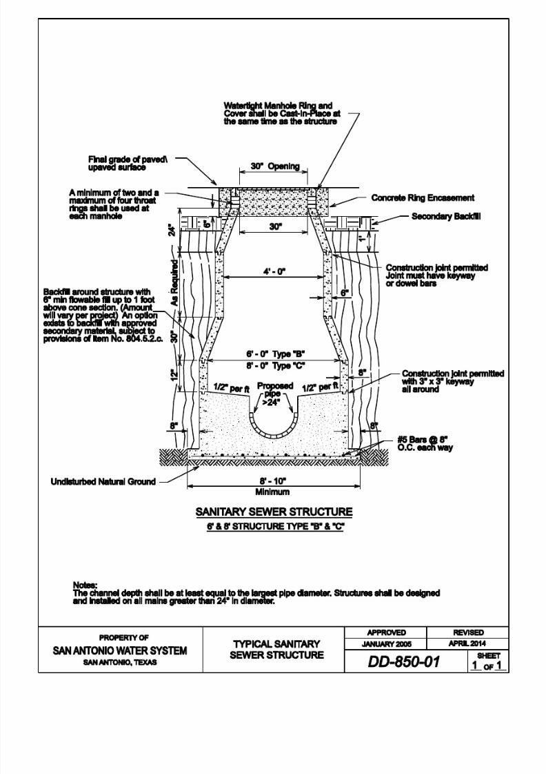
8/21/2019 2014 SAWS Construction Specifications
http://slidepdf.com/reader/full/2014-saws-construction-specifications 262/461

8/21/2019 2014 SAWS Construction Specifications
http://slidepdf.com/reader/full/2014-saws-construction-specifications 263/461
San Antonio Water System Standard Specif ications for Construction
851-1 April 2014
ITEM NO. 851 ADJUSTING EXISTING MANHOLES
851.1 DESCRIPTION: This item shall consist of the adjustment of all existing
manholes, to include the replacing of existing manhole covers and rings
regardless of type shown in the contract documents and in conformity with the
provisions of these specifications or as directed by the Engineer. All manholesshall be watertight and coated with a SAWS-approved sewer coating. The
context of this specification is limited to adjusting the final elevation of the
manhole by the maximum or minimum number of throat rings. Manhole covers
may be either watertight or water resistant, depending upon their specific location.Every manhole cover located in an identified 100-year floodplain, or in the
Edwards Aquifer Recharge Zone, shall be watertight. Sewer manhole ring and
cover castings shall meet the current requirements of AASHTO DesignationM306-10.All manholes requiring adjustments beyond the maximum or minimum
number of throat rings (described herein), shall be subject to Item No. 855,
“Reconstruction of Existing Manholes.”
851.2 SUBMITTALS: Contractor shall submit manufacturer’s product data,
instructions, recommendations, shop drawings, and certifications.
851.3 CONSTRUCTION: Manholes shall be lowered below street subgrade before
placing base materials, and openings shall be protected by temporary hatch
covers. Manholes adjusted in non-paved areas shall be set per proposed final
grade.
Existing manhole rings and covers which are determined by the Inspector to be in
an unacceptable condition, will be removed and replaced with new rings andcovers. If the cone section is removed, the Contractor is to upgrade it to a 30 inch
opening as required by 30 TAC § 217. All manhole openings upgraded to 30
inches shall then be subjected to all provisions of Item No. 855, “Reconstructionof Existing Manholes.” Contractor shall take all necessary measures to prevent
damage to existing or new rings, covers, or cones from equipment and materials
used in, or taken through, the work area. If an existing or new manhole cover,ring, or cone is damaged by the Contractor, it shall be replaced (as directed by the
Inspector) by the Contractor at his own expense. If concrete throat rings are to beinstalled, they must be used in conjunction with a UV stabilized polyethylene
liner and I/I barrier. I/I barrier must meet the following ASTM standards: ASTMD790/1505 Density of Polyethylene Materials, ASTM D1238-10 Melt Flow
Index, ASTM 638-10 Tensile Strength @ Yield (50mm/mm), ASTM 790
Flexural Modulus, ASTM 648 Heat Deflection Temperature @ IGEPAL, ASTM

8/21/2019 2014 SAWS Construction Specifications
http://slidepdf.com/reader/full/2014-saws-construction-specifications 264/461
San Antonio Water System Standard Specif ications for Construction
851-2 April 2014
1693-12 EsCR, 100% IGEPAL/10% IGEPAL.
Manholes shall be adjusted after the street’s base material has been laid and before placing of the final surface course. Manholes that are going to be adjusted
on an existing surface course (not planned for replacement) will be in accordance
to the City of San Antonio Utility Excavation Criteria Manual Standard Drawing No. 8.8, but must first be directed by the Engineer. All manholes shall then be
raised, or lowered a sufficient height so as to be level with the finished surface
course. Adjustment in height will be made by the addition or removal of “throat
rings” above the manhole cone, where feasible. A minimum of two and amaximum of six throat rings may be used at each adjusted manhole.
The standard manhole ring and cover shall be ductile iron and manufactured to
the dimensions shown in the Detail Drawing Series DD-852. The ring and covershall be hinged. Lifting slots cast into the covers shall be provided for lifting
purposes. A water-resistant (cam lock) hinged cover shall be used in areas ofminimal infiltration potential to allow venting. A watertight (bolt down) ring andcovers must be used in areas of high infiltration potential, such as in the Edward’s
Aquifer Recharge Zone, an identified 100-year floodplain, or as otherwise
directed by the Engineer. The nominal cover diameter shall be 32 inches, with a30 inch clear opening, as required by TCEQ. Rings shall have a minimum of four
1 inch holes/slots for anchoring purposes. Rings shall be a minimum of 4-1/2
inches in height or as otherwise accepted by the Engineer. Slots forembedment/lightening are not allowed in ring flanges.
Water-Resistant Rings and Covers: Rings and covers shall have two hinges for
added stability. The hinge shall have a drain to allow for proper debris and foreignobject removal. Prior to acceptance of the work , a stainless steel keyed “cam”
lock shall be provided by the Contractor to the Inspector. When the key is inserted
in the cam, it shall remain in the lid while the cam is in the open (unlocked) position. When in the closed (locked) position, the key can be removed. When not
in use, the cam lock key hole shall be covered with a plastic plug to prevent
infiltration of debris. The cover shall positively lock at 90° to prevent accidental
closure and open fully to 120°. The cover shall also include a single multi-toollifting slot adjacent to the edge of the cover to facilitate opening/lifting/prying
once it is unlocked. Covers shall be provided with a continuous vulcanized (one
piece) EPDM gasket with a shore durometer of 70 ±5 permanently attached to the
cover.
Watertight Rings and Covers: Rings and covers shall be the same as above for
water-resistant version, except the covers shall be bolted to the ring instead ofsecured with the cam lock mechanism. No vent hole(s) shall be provided. A
minimum of four 1/2 inch diameter, stainless steel, hex head bolts shall be

8/21/2019 2014 SAWS Construction Specifications
http://slidepdf.com/reader/full/2014-saws-construction-specifications 265/461
San Antonio Water System Standard Specif ications for Construction
851-3 April 2014
provided for each cover. The 4 bolt holes in the covers shall be evenly spaced
and provided with a minimum 1-½ inch diameter counter sink for the bolt heads.
On the fastened and bolted position, the bolt heads shall not extend above thesurface or the cover. Washers of a size and material as approved by the Engineer
shall be provided for the bolts to insure air and water tightness.
The finished ring and cover shall have the bearing surfaces machined ground and
sets of rings and covers shall be marked in such a way that they can be matched
for assembly in the field. All covers shall have the words "SAN ANTONIO
WATER SYSTEM Sanitary Sewer" cast thereon. Ring and cover shall have theapproved foundry’s name, part number, country of origin preceded by “Made in”
(example: MADE IN USA) in compliance with the country of origin law of 1984,
and production date (example: mm/dd/yy) for tracking purposes. Each casting
must be marked with DI and ASTM A536 or A536 80-55-06 to verify thematerials used. Castings without proper markings shall be rejected.
Material excavation from around the manholes shall be replaced with flowable fillin accordance with these specifications, and select materials from the excavation
(as shown in the contract documents). All excess materials shall be disposed of
by the Contractor at his own expense and in an approved location. TheContractor also has the option of backfilling with approved secondary materials,
subject to the provisions of Item No. 804, “Excavation, Trenching and Backfill.”
851.4 MEASUREMENT: Manholes completely adjusted, as prescribed above, will be
measured by the unit of each manhole adjusted. The excavation and the amount
of flowable fill, reinforced concrete, or any other material as necessary to fill the
area excavated, will not be measured for payment.
851.5 PAYMENT: The work performed as prescribed by this item will be paid for at
the contract unit price bid per manhole for “Adjusting Existing Manholes,” which price shall be full compensation for all excavation, including saw cutting of
surfaces as required, reinforced concrete and disposal of material excavated; for
furnishing and placing all materials and for all labor, tools, equipment and
incidentals necessary to complete the work.
- End of Specification -

8/21/2019 2014 SAWS Construction Specifications
http://slidepdf.com/reader/full/2014-saws-construction-specifications 266/461
San Antonio Water System Standard Specif ications for Construction
852-1 April 2014
ITEM NO. 852
SANITARY SEWER MANHOLES
852.1 DESCRIPTION: This item shall govern the construction of standard sanitary
sewer manholes complete in place and the materials therein, including manhole
rings and covers. All material and construction work shall be in accordance withcurrent Texas Commission on Environmental Quality (TCEQ) rules to include:
Design Criteria for Sewage Systems (30 TCEQ § 217). All constructed manholes
shall be watertight. Manhole covers may be either watertight or water resistant,
depending on their specific location. Every manhole cover located in anidentified 100-year floodplain, or in the Edwards Aquifer Recharge Zone, shall be
watertight. Sewer manhole ring and cover castings shall meet the current
requirements of AASHTO Designation M306-10.
Unless otherwise shown in the contract documents or approved by the Engineer,standard sanitary sewer manholes shall be constructed with influent and effluent
piping less than or equal to 24 inches in diameter with precast reinforced concrete
manhole sections. A standard sanitary sewer manhole shall be a single entrance
cylindrical structure, having a minimum internal diameter of 4feet between thecone and base sections. The base of the structure shall include the load bearing
portion beneath and exterior of the structure, invert channels and the fill or bench
portions adjacent to the lower sewer pipes within the structure. The maximumvertical height of the diameter adjustment section or cone shall be 36 inches.
Adjustment or throat rings may be used for final elevation adjustment of themanhole ring and cover. Concrete encasement of the manhole’s ring shall be as
shown in the DD-852 Standard Drawing Series. Specifically, they shall attach thering and cover to the diameter adjustment section or cone. Manholes which differ
from the above description shall be governed by Item No. 850, "Sanitary Sewer
Structures."
An internal drop manhole shall be required, when sewer lines enter a manhole
more than 24 inches above the manhole invert, while an external drop manholeshall be provided for a sewer entering a manhole more than 30 inches above the
invert. Both conditions will require prior approval by the Engineer.
852.2 SUBMITTALS: Contractor shall submit manufacturer’s product data,instructions, recommendations, shop drawings, and certifications.
852.3 MATERIALS:

8/21/2019 2014 SAWS Construction Specifications
http://slidepdf.com/reader/full/2014-saws-construction-specifications 267/461
San Antonio Water System Standard Specif ications for Construction
852-2 April 2014
1. Precast Reinforced Concrete Manhole Sections: Precast reinforced
concrete manhole sections shall conform to the requirements of ASTM
Designation C478-12a.
2. Mortar: Mortar shall be composed of 1 part Portland Cement, 2 parts sand
and sufficient water to produce a workable mixture. When used to plaster
manholes, it may be composed of 1 part cement to 3 parts sand. Lime upto 10% may be used.
3. Manhole Ring and Cover: The standard manhole ring and cover shall beductile iron and manufactured to the dimensions shown herein. The ring
and cover shall be hinged. Lifting slots cast into the covers shall be
provided for lifting purposes. A water-resistant (cam lock) ring and cover
shall be used in areas of minimal infiltration potential to allow venting. A
watertight (bolt down) ring and cover must be used in areas of highinfiltration potential, such as in the Edward’s Aquifer Recharge Zone, an
identified 100-year floodplain, or as otherwise directed by the Engineer.The nominal cover diameter shall be 32 inches, with a 30 inch clear
opening, as required by TCEQ. Rings shall have a minimum of four 1
inch holes/slots for anchoring purposes. Rings shall be a minimum of 4-
1/2 inches in height, or as otherwise accepted by the Engineer. Slots forembedment/lightening are not allowed in ring flanges.
a. Water-resistant Rings and Covers: Rings and covers shall have twohinges for added stability. The hinge shall have a drain to allow for
proper debris and foreign object removal. Prior to acceptance ofthe work, a stainless steel keyed “cam” lock shall be provided by
the Contractor to the Inspector. When the key is inserted in thecam, it shall remain in the lid while the cam is in the open
(unlocked) position. When in the closed (locked) position, the key
can be removed. When not in use, the cam lock key hole shall becovered with a plastic plug to prevent infiltration of debris. The
cover shall positively lock at 90° to prevent accidental closure and
open fully to 120°. The cover shall also include a single multi-toollifting slot adjacent to the edge of the cover to facilitate
opening/lifting/prying once it is unlocked. Covers shall be
provided with a continuous vulcanized (one piece) EPDM gasketwith a shore durometer of 70 ±5 permanently attached to the cover.
b. Watertight Rings and Covers: Rings and covers shall be the same
as above for water-resistant version, except the covers shall be
bolted to the ring instead of secured with the cam lock mechanism.

8/21/2019 2014 SAWS Construction Specifications
http://slidepdf.com/reader/full/2014-saws-construction-specifications 268/461
San Antonio Water System Standard Specif ications for Construction
852-3 April 2014
No vent hole(s) shall be provided. A minimum of four 1/2 inch
diameter, stainless steel, hex head bolts shall be provided for each
cover. The 4 bolt holes in the covers shall be evenly spaced and
provided with a minimum 1-½ inch diameter counter sink for the bolt heads. On the fastened and bolted position, the bolt heads shall
not extend above the surface or the cover. Washers of a size and
material as approved by the Engineer shall be provided for the bolts to insure air and water tightness.
The finished ring and cover shall have the bearing surfaces machinedground and sets of rings and covers shall be marked in such a way that
they can be matched for assembly in the field. All covers shall have the
words "SAN ANTONIO WATER SYSTEM Sanitary Sewer" cast thereon.
Ring and cover shall have the approved foundry’s name, part number,
country of origin preceded by “Made in” (example: MADE IN USA) incompliance with the country of origin law of 1984, and production date
(example: mm/dd/yy) for tracking purposes. Each casting must be markedwith DI and ASTM A536 or A536 80-55-06 to verify the materials used.
Castings without proper markings shall be rejected.
4. Throat Rings: Throat rings shall be made of either HDPE or reinforcedconcrete and have a maximum thickness of 2 inches. The internal
diameter shall match that of the ring and cover’s opening. Concrete shall
conform to the provisions of Item No. 300 "Concrete (NaturalAggregate)." If concrete throat rings are to be utilized, they must be used
in conjunction with a UV stabilized polyethylene liner. I/I barrier mustmeet the following ASTM standards: ASTM D790/1505 Density of
Polyethylene Materials, ASTM D1238-10 Melt Flow index, ASTM 638-10 Tensile Strength @ Yield (50mm/mm), ASTM 790-10 Flexural
Modulus, ASTM 648-07 Heat Deflection Temperature @IGEPAL, ASTM
1693-12 EsCR, 100% IGEPAL/10% IGEPAL. A minimum of two and amaximum of four throat rings may be used at each manhole installed.
5. Coating: All manholes shall be watertight and coated with a SAWS-approved sewer coating. Prior to coating, all manholes shall be vacuum
tested, and approved.
For existing and rehabilitated manholes, apply a combination of both products with the cementitious coating first, followed by the epoxy
coating. Kerneos SewperCoat 2000 HR regular, applied at the required
one inch thick application, is the only product approved which does not
require a subsequent epoxy coating. New manholes installed do not

8/21/2019 2014 SAWS Construction Specifications
http://slidepdf.com/reader/full/2014-saws-construction-specifications 269/461
San Antonio Water System Standard Specif ications for Construction
852-4 April 2014
require the cementitious coating. Other approved materials are as follows:
a. Cementitious coating: With required one inch thick application:
(1) Permaform CR-5000;
(2) Strong - Seal MS-2C;
(3) Standard Cement Material Inc. Reliner;
(4) Quadex Aluminaliner;
(5) ConShield Biotech Armor.
b.
Epoxy coating: With specified thickness application:
(1) Raven 405 Series High Build Epoxy Liner: Requiredthickness – 125 mils;
(2) Spray Wall polyurethane System: Required thickness – 125
mils;
(3) Carboline “Plasite 4500” System: Required thickness – 125
mils.
852.4 CONSTRUCTION: Manholes shall be constructed of materials andworkmanship as prescribed by these specifications, at such places shown in the
contract documents or as designated by the Engineer, and in conformity with thetypical details and sketches shown.
1. Footings or bases of manholes shall be a minimum of 6 inches in depth below the bottom of the pipe.
2. All invert channels shall be constructed and shaped accurately so as to besmooth, uniform and cause minimum resistance to flow. The bench shall
be finished smooth with a slope of ½ inch per foot from the manhole walls
to the edges of the invert. The top half of all sewer pipes within the invertchannel or bench zone shall be removed flush to the inside manhole walls.
3. Joints on sewer pipes shall not be cast or constructed within the wall
sections of manholes.

8/21/2019 2014 SAWS Construction Specifications
http://slidepdf.com/reader/full/2014-saws-construction-specifications 270/461
San Antonio Water System Standard Specif ications for Construction
852-5 April 2014
4. Concrete cradles shall be required for new pre-cast manholes. Concrete
cradles shall extend beyond the outside walls of the manhole a minimum
of 36 inches.
5. Voids between exterior pipe walls and manhole walls at all pipe
connections in manholes shall be filled with a non-shrink grout, concrete
or mortar, as approved by the Engineer or as shown in the contractdocuments and inspected prior to backfilling.
6. Where connections to existing manholes are required, the adjacent pipe bedding shall be prepared to proper grade, the existing manhole neatly cut
and the new pipe inserted so that the end is projecting 2 inches from the
inside wall. The invert shall then be reshaped to properly channel new
flows. Debris of any kind shall be kept out of new or existing manholes or
mains.
7. Throat rings shall be mortared between all bearing surfaces sufficient to provide a minimum, in place, mortar thickness of ¼ inch. No more than 4
throat rings may be used on any new manhole or no more than 21 inches
from the top of the cone to the top of the ring and cover.
8. Manhole Ring Encasement: All manhole rings shall be encased with
4,000 psi reinforced concrete as shown in the contract documents or as
approved by the Engineer.
a. Concrete manhole ring encasement shall extend 6 inches below thetop of the cone and have a minimum width when measured at the
manhole ring of 1 foot. The surface of the encasement shall beflush with the top of the manhole ring.
b. Where manholes are constructed in existing streets and wheredirected by the Engineer or shown in the contract documents, the
exterior exposed surfaces of the ring, mortar; throat rings and
manhole surface shall be coated with a ⅛ inch minimum thicknessof mastic or plastic prior to placement of concrete.
852.5 TESTING: The Contractor shall perform the testing for all sanitary sewermanholes in accordance with the following.
1. Leakage Testing: All manholes must pass a leakage test. The contractor
shall test each manhole (after assembly and backfilling) for leakage,
separate and independent of all other sanitary sewer piping, by means of

8/21/2019 2014 SAWS Construction Specifications
http://slidepdf.com/reader/full/2014-saws-construction-specifications 271/461
San Antonio Water System Standard Specif ications for Construction
852-6 April 2014
either a hydrostatic test, vacuum test, or other methods approved by the
Engineer. The Contractor is hereby instructed to conduct either of the two
identified tests in the following manner:
a. Hydrostatic Testing: Hydrostatic testing shall be conducted by
utilizing approved plugs to seal all influent and effluent pipes in
the manhole and filling the manhole to the top of the cone withwater. Additional water may be added over a 24-hour period to
compensate for absorption and evaporation losses. At the
conclusion of the 24-hour saturation period, the manhole shall befilled to the top and observed. Any measureable loss within a 30
minute period shall be considered an unsuccessful test and thus
require the Contractor to assess the needed repairs, perform such
repairs (subject to the approval of the Engineer), and notify the
Inspector when the retest will be performed. All effort, materials,or other costs shall be solely at the Contractor’s expense.
b. Vacuum Testing:
(1) General: Manholes shall be tested after
construction/installation and backfilling with allconnections (existing and/or proposed) in place. Drop-
connections and gas sealing connections shall be installed
prior to testing.
(2) Test Procedure: The lines entering the manhole shall betemporarily plugged with the plugs braced to prevent them
from being drawn into the manhole. The plugs shall beinstalled in the lines beyond drop connections, gas sealing
connections, etc. Prior to performing the test, the
Contractor shall plug all lift holes and exterior joints with anon-shrink grout and plug all pipes entering the manhole.
No grout shall be placed in horizontal joints prior to testing.
Contractor shall use a minimum 60 inch/lb torque wrenchto tighten the external clamps that secure the test cover to
the top of the manhole. The test head shall be inflated in
accordance with the manufacturer's recommendations. Avacuum of 10 inches of mercury shall be drawn, and thevacuum pump will be turned off. With the valve closed,
the level vacuum shall be read after the required test time.
If the drop in the level is less than 1 inch of mercury (final
vacuum greater than 9 inches of mercury), the manhole

8/21/2019 2014 SAWS Construction Specifications
http://slidepdf.com/reader/full/2014-saws-construction-specifications 272/461
San Antonio Water System Standard Specif ications for Construction
852-7 April 2014
will have passed the vacuum test. The required test time is
2 minutes.
(3) Acceptance: Manholes will be accepted with relation tovacuum test requirements, if they meet the criteria above.
Any manhole which fails the initial test must be repaired
with a non-shrink grout or other suitable material based onthe material of which the manhole is constructed. The
manhole shall be retested as described above until a
successful test is attained. After a successful test, thetemporary plugs will be removed. To ensure that the plugs
have been removed, Contractor shall only do so in the
presence of the Inspector.
(4) Repairs to Existing Manholes: Any existing manholewhich fails to pass the vacuum test shall be closely
examined by the Inspector and the Contractor to determineif the manhole can be repaired. Thereafter, the Contractor
shall either repair or remove and replace the manhole as
directed. The manhole shall then be retested and coated
with a SAWS-approved sewer coating as stated above. TheOwner may elect to simply remove and replace the existing
manhole with a new one. Any manhole excavated for
repairs or excavated for tie in, shall be backfilled withflowable fill up to 1 foot below the top of the cone. The
Contractor also has the option of backfilling with approvedsecondary materials, subject to the provisions of Item No.
804, “Excavation, Trenching and Backfill.”
(5) Measurement and Payment: Vacuum testing of new
structures will not be a pay item. The cost of this work will be included in the bid price for the new manhole. Each
vacuum test of an existing manhole shall be a separate pay
item. Repairs to existing manholes shall be a separate payitem when authorized.
2.
Holiday Testing: Inspect each sanitary sewer manhole using high-voltageholiday detection equipment. All detected holidays shall be marked andrepaired by abrading the coating surface with grit disk paper, or other hand
tooling method. After abrading and cleaning, additional protective coating
material shall be applied to the repair area. All touch-up repair procedures
shall follow the protective coating manufacturer’s recommendations.

8/21/2019 2014 SAWS Construction Specifications
http://slidepdf.com/reader/full/2014-saws-construction-specifications 273/461
San Antonio Water System Standard Specif ications for Construction
852-8 April 2014
If a sanitary sewer manhole fails to pass one of the above tests, it shall be repaired
in accordance with the manufacturer’s recommendations and re-tested. It shall
not be accepted until it passes all tests. All repairs and re-testing shall be at noadditional cost to SAWS.
852.6 MEASUREMENT:
1. All manholes zero feet to 6 feet deep and designated in the contract
documents will be measured as the total number of such manholesconstructed, including those exceeding 6 feet in depth from the lowest
invert elevation to the top of the ring.
2. Manholes deeper than 6 feet shall be measured by the number of vertical
feet in excess of 6 feet.
852.7 PAYMENT:
1. All manholes shall be paid at the contract unit price bid for each such
manhole, which price shall be full compensation for all precast sections or
throat rings, UV stabilized polyethylene liner, cones, bases, rings andcovers, manhole ring encasement, concrete, flowable fill, mortar, drop
pipes and fittings, labor, tools, equipment, testing, tees, wyes, and
incidentals necessary to complete the work.
2. Extra depth manholes shall be paid for at the contract unit price bid pervertical foot as measured above.
3. Concrete cradles for pipes shall be measured and paid for at the contract
unit price bid as provided for in Item No. 858, "Concrete Encasement,
Cradles, Saddles and Collars."
4. Gravel subgrade filler for manholes shall not be measured separately for
payment.
- End of Specification -

8/21/2019 2014 SAWS Construction Specifications
http://slidepdf.com/reader/full/2014-saws-construction-specifications 274/461

8/21/2019 2014 SAWS Construction Specifications
http://slidepdf.com/reader/full/2014-saws-construction-specifications 275/461
Standard Manhole Ring and Cover :
All applicable dimensions shall
Note:
here
conform to the dimensions shown
VENTED MANHOLE RING AND COVER
Vented Manhole
1 Dia. Cast Hole
Lift Slot for Lifting Bar
Ring and Cover
O-Ring groove shall be
Note:
Machine ground
The bearing surfaces and
WATERTIGHT MANHOLE
INSERT DETAIL
VENT HOLE DETAIL
1
Top of vent hole to be same
height as adjacent ribs
ip of insert to provide access
SECTION A-A
Slots or holes may be cu t in
for bolts in watertight lids
Gas relief valves
REVISED
JANUARY 2005
APPROVED
SHEET
OF
AND COVER DETAIL
VENTED MANHOLE RING
APRIL 2014
Ma nhole cover inserts shall be installed in strict accordance with the man ufacturer’s recommen dations.
The contractor shal l be responsible for making the necessary f ield measurements for the manufacturer
prior to production.
PRO PERTY O F
S N NTONIO W TER SYSTEM
SAN ANTONIO, TEXAS
(WHEN SPECIFIED)

8/21/2019 2014 SAWS Construction Specifications
http://slidepdf.com/reader/full/2014-saws-construction-specifications 276/461

8/21/2019 2014 SAWS Construction Specifications
http://slidepdf.com/reader/full/2014-saws-construction-specifications 277/461

8/21/2019 2014 SAWS Construction Specifications
http://slidepdf.com/reader/full/2014-saws-construction-specifications 278/461

8/21/2019 2014 SAWS Construction Specifications
http://slidepdf.com/reader/full/2014-saws-construction-specifications 279/461

8/21/2019 2014 SAWS Construction Specifications
http://slidepdf.com/reader/full/2014-saws-construction-specifications 280/461

8/21/2019 2014 SAWS Construction Specifications
http://slidepdf.com/reader/full/2014-saws-construction-specifications 281/461

8/21/2019 2014 SAWS Construction Specifications
http://slidepdf.com/reader/full/2014-saws-construction-specifications 282/461
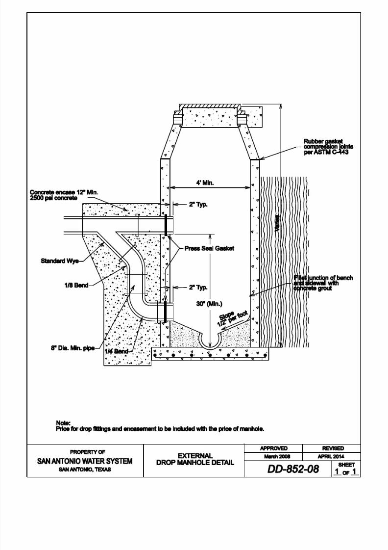
8/21/2019 2014 SAWS Construction Specifications
http://slidepdf.com/reader/full/2014-saws-construction-specifications 283/461

8/21/2019 2014 SAWS Construction Specifications
http://slidepdf.com/reader/full/2014-saws-construction-specifications 284/461

8/21/2019 2014 SAWS Construction Specifications
http://slidepdf.com/reader/full/2014-saws-construction-specifications 285/461
San Antonio Water System Standard Specif ications for Construction
853- 1 April 2014
ITEM NO. 853
SANITARY SEWER GLASS-FIBER
REINFORCED POLYESTER (FRP) MANHOLES
853.1 DESCRIPTION: This item shall govern the construction of FRP sanitary sewer
manholes, complete in place and the materials therein, including manhole ring
and covers. All material and construction work shall be in accordance withcurrent Texas Commission on Environmental Quality (TCEQ) rules to include:
Design Criteria for Sewage Systems (30 TCEQ § 217), or any revisions thereto as
applicable. All constructed FRP manholes shall be watertight. Manhole covers
may be either watertight or water resistant, depending on their specific location.Every manhole cover located in an identified 100-year floodplain, or in the
Edwards Aquifer Recharge Zone, shall be watertight. Sewer manhole ring and
cover castings shall meet the current requirements of AASHTO DesignationM306-10.
853.2 SUBMITTALS: Contractor shall submit manufacturer’s product data,
instructions, recommendations, shop drawings, and certifications.
853.3 MATERIALS:
1. FRP Manholes: All manholes shall be watertight. Glass-Fiber ReinforcedPolyester Manholes shall be a one-piece monolithic designed unit
constructed of glass-fiber reinforced, supplier-certified, unsaturated
isophthalic polyester resin containing chemically enhanced silica toimprove corrosion resistance, strength and overall performance. FRP
manholes shall be manufactured in strict accordance with ASTM D3753-
12.
2. Exterior Surface: For a UV inhibitor, the resin on the exterior surface of
the manhole shall have gray pigment added for a minimum thickness of
0.125 inches.
3. Dimension: Manholes shall be a circular cylinder, reduced at the top to a
circular manway not smaller than 30 inches (inside diameter). Manholes
shall also be produced in whole foot increments of length +/- 2 inches. Nominal inside diameter shall be 48 inches. Tolerance on the inside
diameter shall be +/- 1%. The minimum wall thickness for all FRP
manholes (all depths) shall be 0.50 inches. Unless otherwise shown in thecontract documents or approved by the Engineer, standard sanitary sewer
FRP manholes shall be constructed on influent or effluent pipes less than

8/21/2019 2014 SAWS Construction Specifications
http://slidepdf.com/reader/full/2014-saws-construction-specifications 286/461
San Antonio Water System Standard Specif ications for Construction
853- 2 April 2014
24 inches in diameter. The maximum vertical height of the diameteradjustment section or cone shall be 36 inches.
4.
Configuration: The manway reducer must provide a bearing surface onwhich a standard ring and cover may be supported and adjusted to grade.
The reducer shall be joined to the barrel section at the factory with resin
and glass fiber reinforcement, thus providing the required monolithicdesign to prevent infiltration and/or exfiltration through the manhole.
5. Class: Manholes shall be manufactured in one class of load rating. This
class shall be AASHTO H-20 wheel load.
6. Stub-outs and Connections: Several methods exist that may be used to
connect primary and secondary lines to manholes, and these shall be
performed per the Engineer’s request. The most common of thesemethods include: installation of SDR PVC sewer pipe stub-outs to the
manhole, Kor-N-Seal boots, or Insert-a-Tee fittings in the manhole wall.
Installation of SDR PVC sewer pipe must be performed by sanding, priming, and using resin fiber-reinforced hand lay-up. The resin and
fiberglass shall be the same type and grade as used in the fabrication of the
fiberglass manhole. Kor-N-Seal boots may be installed by the manholemanufacturer using fiberglass reinforced pipe stub-out for Kor-N-Seal
boot sealing surface. Insert-a-Tee fittings maybe installed only with the
approval of the Engineer, and shall be installed per the manufacturers’
instructions.
7. Manhole Bottom: Manholes are required to have a resin fiber-reinforced
bottom. Deeper manholes (> 6 feet) may require a minimum of two 1½inches deep x 3½ inches wide stiffening ribs, completely enclosed with
resin fiber-reinforcement. All fiberglass manholes with a fiberglass bottom
will have a minimum 3 inch anti-flotation ring. Manhole bottoms shall be
a minimum ½ inch thick.
8. Marking and Identification: All manholes shall be marked in letters no
less than 1 inch in height with the following information:
Manufacturer’s name or trademark; Manufacturer’s factory location;
Manufacturer’s serial number; Manhole length;
ASTM Designation;

8/21/2019 2014 SAWS Construction Specifications
http://slidepdf.com/reader/full/2014-saws-construction-specifications 287/461
San Antonio Water System Standard Specif ications for Construction
853- 3 April 2014
Installation assist marks (vertical lines 90o apart at base of
manhole).
9.
Manhole Rings and Covers: The standard manhole ring and cover shall beductile iron and manufactured to the dimensions shown herein. The ring
and cover shall be hinged and the cover may contain a hole or opening for
venting, depending upon their specific location. Lifting slots cast into thecovers shall be provided for lifting purposes. A water-resistant (cam lock)
ring and cover shall be used in areas of minimal infiltration potential to
allow venting. A watertight (bolt down) ring and cover must be used in
areas of high infiltration potential, such as in the Edward’s AquiferRecharge Zone, an identified 100-year floodplain, or as otherwise directed
by the Engineer. The nominal cover diameter shall be 32 inches, with a 30
inch clear opening, as required by TCEQ. Rings shall have a minimum of
four 1 inch holes/slots for anchoring purposes. Rings shall be a minimumof 4-1/2 inches in height, or as otherwise accepted by the Engineer. Slots
for embedment/lightening are not allowed in ring flanges.
a. Water-resistant Rings and Covers: Rings and covers shall have two
hinges for added stability. The hinge shall have a drain to allow for
proper debris and foreign object removal. Prior to acceptance ofthe work, a stainless steel keyed “cam” lock shall be provided by
the Contractor to the Inspector. When the key is inserted in the
cam, it shall remain in the lid while the cam is in the open
(unlocked) position. When in the closed (locked) position, the key
can be removed. When not in use, the cam lock key hole shall becovered with a plastic plug to prevent infiltration of debris. The
cover shall positively lock at 90° to prevent accidental closure andopen fully to 120°. The cover shall also include a single multi-tool
lifting slot adjacent to the edge of the cover to facilitate
opening/lifting/prying once it is unlocked. Covers shall be
provided with a continuous vulcanized (one piece) EPDM gasketwith a shore durometer of 70 ±5 permanently attached to the cover.
b. Watertight Rings and Covers: Rings and covers shall be the sameas above for water-resistant version, except the covers shall be
bolted to the ring instead of secured with the cam lock mechanism. No vent hole(s) shall be provided. A minimum of four 1/2 inch
diameter, stainless steel, hex head bolts shall be provided for eachcover. The 4 bolt holes in the covers shall be evenly spaced and
provided with a minimum 1-½ inch diameter counter sink for the
bolt heads. On the fastened and bolted position, the bolt heads shall

8/21/2019 2014 SAWS Construction Specifications
http://slidepdf.com/reader/full/2014-saws-construction-specifications 288/461
San Antonio Water System Standard Specif ications for Construction
853- 4 April 2014
not extend above the surface or the cover. Washers of a size andmaterial as approved by the Engineer shall be provided for the
bolts to insure air and water tightness.
The finished ring and cover shall have the bearing surfaces machined
ground and sets of rings and covers shall be marked in such a way that
they can be matched for assembly in the field. All covers shall have thewords "SAN ANTONIO WATER SYSTEM Sanitary Sewer" cast thereon.
Ring and cover shall have the ap proved foundry’s name, part number,
country of origin preceded by “Made in” (example: MADE IN USA) in
compliance with the country of origin law of 1984, and production date(example: mm/dd/yy) for tracking purposes. Each casting must be marked
with DI and ASTM A536 or A536 80-55-06 to verify the materials used.
Castings without proper markings shall be rejected.
10. Throat Rings: Throat rings shall be made of either HDPE or reinforced
concrete and have a maximum thickness of 2 inches. The internal
diameter shall match that of the ring and cover’s opening. Concrete shallconform to the provisions of Item No. 300 "Concrete (Natural
Aggregate)." If concrete throat rings are to be utilized, they must be used
in conjunction with a UV stabilized polyethylene liner. I/I barrier mustmeet the following ASTM standards: ASTM D790/1505 Density of
Polyethylene Materials, ASTM D1238-10 Melt Flow index, ASTM 638-
10 Tensile Strength @ Yield (50mm/mm), ASTM 790-10 Flexural
Modulus, ASTM 648-07 Heat Deflection Temperature @IGEPAL, ASTM
1693-12 EsCR, 100% IGEPAL/10% IGEPAL. A minimum of two and amaximum of four throat rings may be used at each manhole installed.
11. Mortar: Mortar shall be composed of 1 part Portland Cement, 2 parts sand
and sufficient potable water to produce a working mixture.
12. Membrane Curing Compound: All membrane curing compound shallconform to the provisions of TxDOT’s DMS-4650, “Hydraulic Cement
Concrete Curing Materials and Evaporation Retardants.”
13. Concrete Encasements: Concrete encasement shall conform to Item No.
852, “Sanitary Sewer Manholes.” Specifically, refer to Standard DetailDrawing DD-852-03.
14. Reinforcing Steel: All reinforcing steel shall conform to provisions of
Item No. 301, “Reinforcing Steel.”

8/21/2019 2014 SAWS Construction Specifications
http://slidepdf.com/reader/full/2014-saws-construction-specifications 289/461
San Antonio Water System Standard Specif ications for Construction
853- 5 April 2014
15. Initial and Secondary Backfill Material: Refer to Item No. 804.5 for all backfill requirements.
853.4 CONSTRUCTION:
1. Manholes shall be constructed of materials and workmanship as
prescribed by these specifications, at such places shown in the contractdocuments and in conformity with the typical details.
2. Fiberglass manholes must be installed according to manufacturer’s
installation instructions. In addition to these instructions, local codes mayapply and should be consulted as applicable in manhole installation.
Correct manhole installation requires proper concrete foundation, good
backfill and proper handling to prevent manhole damage and insure long-
term corrosion resistant service.
3. Prepare excavation at manhole location should be at least wide enough to
accommodate the slab specified and to provide working room aroundmanhole. Ensure the depth of manhole is sufficient to allow between two
and four concrete rings for adjustment of ring and cover at top of final
grade. Quarter marks have been provided on barrel to facilitate alignment.
4. Manhole Base: Use initial backfill material to provide 4 to 6 inches of
leveling base.
5.
Set Manhole: To lift manhole, insert 4 inches x 4 inches timber crosswiseinside the manhole to the underside of the collar with a rope or woven
fabric slings attached to backhoe or other lifting device and lower themanhole. Level manhole and connect sewer lines to manhole. A concrete
base encasement shall be placed at least 12 inches from the manhole and
shall come over the top of the anti-flotation ring a minimum of 12 inches.
6. Invert and Bench Area: The invert and bench area can be formed with wet
concrete and finished with an epoxy sealant.
7. Backfill Material: Initial backfill material shall be used for backfill around
the manhole for a minimum distance of one foot from the outside surfaceand extending from the bottom of the excavation to the top of the reducer
section. Secondary backfill material may be used for the remainder of the backfill, subject to pre-approval by the Engineer. An approved flowable
fill material may also be used for backfilling operations.

8/21/2019 2014 SAWS Construction Specifications
http://slidepdf.com/reader/full/2014-saws-construction-specifications 290/461
San Antonio Water System Standard Specif ications for Construction
853- 6 April 2014
8. Backfill Procedure: Backfill material shall be placed in layers of not morethan 12 loose measure inches and mechanically tamped to 98% Standard
Proctor Density. Refer to Item No. 804, “Excavation, Trenching and
Backfill” for more specific measures for backfill and compactionrequirements. Flooding will not be permitted. Backfill shall be placed in
such a manner as to prevent any wedging action against the fiberglass
manhole structure.
9. Testing: All structures must pass a leakage test. The Contractor shall test
each structure (after assembly and backfilling) for leakage, separate and
independent of the all other sanitary sewer piping, by means of either ahydrostatic test, vacuum test, or other methods approved by the Engineer.
Contractor is hereby instructed to conduct either of the two identified tests
in the following manner:
a. Hydrostatic Testing: Hydrostatic testing shall be conducted by
utilizing approved plugs to seal all influent and effluent pipes inthe structure and filling the structure to the top of the structure with
water. Additional water may be added over a 24 hour period to
compensate for absorption and evaporation losses. At theconclusion of the 24 hour saturation period, the structure shall be
filled to the top of the structure and observed. Any measureable
loss within a 30 minute period shall be considered an unsuccessful
test and thus require the Contractor to assess the needed repairs,
perform such repairs (subject to the approval of the Engineer), andnotify the Inspector when the retest will be performed. All effort,
materials, or other costs shall be solely at the Contractor’s expense.
b. Vacuum Testing:
(1) General: Structures shall be tested afterconstruction/installation and backfilling with all
connections (existing and/or proposed) in place. Drop-
connections and gas sealing connections shall be installed prior to testing.
(2) Test Procedure: The lines entering the structure shall be
temporarily plugged with the plugs braced to prevent themfrom being drawn into the structure. The plugs shall be
installed in the lines beyond drop connections, gas sealing
connections, etc. Prior to performing the test, the

8/21/2019 2014 SAWS Construction Specifications
http://slidepdf.com/reader/full/2014-saws-construction-specifications 291/461
San Antonio Water System Standard Specif ications for Construction
853- 7 April 2014
contractor shall plug lift holes and exterior joints with anon-shrink grout and plug all pipes entering the structure.
No grout shall be placed in horizontal joints prior to testing.
Contractor shall use a minimum 60 inch/lb torque wrenchto tighten the external clamps that secure the test cover to
the top of the structure. The test head shall be inflated in
accordance with the manufacturer's recommendations. Avacuum of 10 inches of mercury shall be drawn, and the
vacuum pump will be turned off. The test does not begin
until after the vacuum pump is off. With the valve closed,
the level vacuum shall be read after the required test time.If the drop in the level is less than 1 inch of mercury (final
vacuum greater than 9 inches of mercury), the structure will
have passed the vacuum test. The required test time is 2
minutes.
(3) Acceptance: Structures will be accepted with relation to
vacuum test requirements, if they meet the criteria above.Any structure which fails the initial test must be repaired
with a non-shrink grout or other suitable material based on
the material of which the structure is constructed.Structures shall be repaired on the exterior surface only.
The structure shall be retested as described above until a
successful test is attained. After a successful test, the
temporary plugs will be removed. To ensure that the plugs
have been removed, Contractor shall only do so in the presence of the Inspector.
(4) Repairs to Existing Structures: Any existing structure
which fails to pass the vacuum test shall be closely
examined by the Inspector and the Contractor to determine
if the structure can be repaired. Thereafter, the Contractorshall either repair or remove and replace the structure as
directed. The structure shall then be retested and coated
with a SAWS-approved structural coating as stated above.The Owner may elect to simply remove and replace the
existing structure with a new one. Any structure excavatedfor repairs or excavated for tie in, shall be backfilled with
flowable fill up to 1 foot below the top of thestructure/cone. The Contractor also has the option of
backfilling with approved secondary materials, subject to
the provisions of Item No. 804, “Excavation, Trenching

8/21/2019 2014 SAWS Construction Specifications
http://slidepdf.com/reader/full/2014-saws-construction-specifications 292/461
San Antonio Water System Standard Specif ications for Construction
853- 8 April 2014
and Backfill.”
(5) Measurement and Payment: Vacuum testing of new
structures will not be a pay item. The cost of this work will be included in the bid price for the new structure. Each
vacuum test of an existing structure shall be a separate pay
item. Repairs to existing structures shall be a separate payitem when authorized.
853.5 MEASUREMENT
1. FRP sanitary sewer manholes (0 to 6 feet deep) as designated in the
contract documents shall be measured as the total number of such
manholes constructed, including those exceeding 6 feet in depth from the
lowest invert elevation to the top of the ring.
2. Manholes deeper than 6 feet shall be measured by the number of vertical
feet in excess of 6 feet.
853.6 PAYMENT
1. FRP sanitary sewer manholes shall be paid at the contract unit price bid
for each such manhole. The price shall be full compensation for all precast
sections or throat rings, cones, rings and covers, manhole reinforced
concrete ring encasement, flowable fill, manhole concrete base
encasement, concrete mortar, drop pipes and fittings, initial backfillmaterial, labor, tools, equipment testing, tees, wyes, and incidentals
necessary to complete the work.
2. Extra depth manholes (> 6 feet) shall be paid for at the contract unit price
bid per vertical foot as measured above.
3. Gravel subgrade filler for manholes shall not be measured separately for
payment.
- End of Specification -

8/21/2019 2014 SAWS Construction Specifications
http://slidepdf.com/reader/full/2014-saws-construction-specifications 293/461
San Antonio Water System Standard Specif ications for Construction
854-1 April 2014
ITEM NO. 854
SANITARY SEWER LATERALS
854.1 DESCRIPTION: This item shall govern sanitary sewer laterals installed in
accordance with these specifications and as directed by the Engineer. This item
shall also consist of the installation of a two-way sewer cleanout at the propertyline.
854.2 SUBMITTALS: Contractor shall submit manufacturer’s product data,
instructions, recommendations, shop drawings, and certifications.
854.3 MATERIALS: The materials for sanitary sewer laterals shall conform to the
specification contained in Item No. 848, "Sanitary Sewers."
854.4 CONSTRUCTION:
1. Sanitary sewer laterals fittings and appurtenances shall conform to thematerial specifications and shall be installed by the Contractor as specified
herein, or as directed by the Inspector or the Engineer and in accordance
with the DD-854 Standard Drawing Series. When the lateral is within theEdwards Underground Recharge Zone, it shall be installed in accordance
with Standard Drawing DD-854-ERZD.
2. Designation of Lateral: A sewer pipe located between the sanitary sewermain and the customer ’s premise, is designated as a "sanitary sewer
lateral."
3. Lateral Installation: All lateral installations shall be performed in
accordance with Item Nos. 848; "Sanitary Sewers" 804, "Excavation,
Trenching and Backfill," and as described herein. For sanitary sewermains that are 12 inch in diameter or smaller, all laterals shall be
connected using the appropriate size tee/wye placed in line with the main
line. For mains larger than 12 inch, insert-a-tee conforming to ASTM
3034-08, or approved or equal, shall be used. Where waterline crossingswith sanitary sewer laterals are less than the regulated separation
distances, all lateral piping shall be SDR-26 PVC pipe (ASTM D2241-09),
with a pressure rating of 150 psi.
Connection to the customer ’s end of the lateral shall be performed using a
flexible coupling, or pre-approved equal. All flexible couplings shall be
concrete-encased to prevent movement or breakage of the steel bands. All

8/21/2019 2014 SAWS Construction Specifications
http://slidepdf.com/reader/full/2014-saws-construction-specifications 294/461
San Antonio Water System Standard Specif ications for Construction
854-2 April 2014
cleanouts at job sites shall have installed an approved heavy duty sanitary
sewer cap.
Cutting, excavation, and backfill shall be as specified herein and inaccordance with applicable sections of Item No. 804, "Excavation,
Trenching, Backfill."
854.5 MEASUREMENT: Sanitary sewer laterals shall be measured by the linear feet
installed at the various diameter sizes. The measured dimension shall be taken
from the centerline of the main to the connection at – or just inside – thecustomer's property line. Measurement will be continuous through any fittings in
the main.
854.6 PAYMENT: Sanitary sewer laterals shall be paid for at the contract bid price per
linear foot complete in place for the type, and size constructed. Price shall be fullcompensation for furnishing all materials, including pipe, pipe fittings (to include
wyes, tees, bends), pumping, bedding, trenching or boring, trench protection, backfilling, tamping, cutting pavement and surface structures of whatever type
encountered and replacement with whatever type specified and other incidentals
required to complete the work.
When the minimum separation distances for any water and sewer piping facilities
cannot be maintained per 30 TAC §217.53, contractor shall install SDR-26 PVC
pipe (150 psi pressure rated). Payment for this higher pressure rated pipe shall bemade at the contract bid price per linear foot complete in place for the type and
size constructed.
Payment for the installation of the two-way cleanout shall be paid per each underthe applicable line item. Only one-way cleanouts are required on the termination
point of a dead-end main.
- End of Specification -

8/21/2019 2014 SAWS Construction Specifications
http://slidepdf.com/reader/full/2014-saws-construction-specifications 295/461

8/21/2019 2014 SAWS Construction Specifications
http://slidepdf.com/reader/full/2014-saws-construction-specifications 296/461
SEWER
or plastic pipe
Approved Cas t
Approved Cap
Backfil l to top of 1 /8 Bend
with 1 maximum aggregate
Standard 1/8 Bend
Close end with clay cap
and grout in place or use
mechanical joint plug
Standard Wye branch
1
8
1
5
1
12
12
Top of Pavement
(Heavy Duty)
PROPERTY OF
S N NTONIO W TER SYSTEM
SAN ANTONIO, TEXAS
APPROVED
MARCH 2008
REVISED
SHEET
OF
Sewer Main
6 or 8 Pipe / Fit t ings
Concrete
Encasemen t
Iron Sewer Cap *
Section of 8 metall ic
* Approved Gate Cap
TYPICAL 6 OR 8 CLEANO UT
DETAIL
(ON DEAD-END MAIN)
APRIL 2014
Note: De pending upo n the type of service that an 8 inch lateral (on a dead end m ain) is providing, A standard
manho le in liev of is cleanout may be required. Consult with the SAW S Inspector.

8/21/2019 2014 SAWS Construction Specifications
http://slidepdf.com/reader/full/2014-saws-construction-specifications 297/461

8/21/2019 2014 SAWS Construction Specifications
http://slidepdf.com/reader/full/2014-saws-construction-specifications 298/461

8/21/2019 2014 SAWS Construction Specifications
http://slidepdf.com/reader/full/2014-saws-construction-specifications 299/461
San Antonio Water System Standard Specif ications for Construction
855-1 April 2014
ITEM NO. 855
RECONSTRUCTION OF EXISTING MANHOLES
855.1 DESCRIPTION: This item shall consist of the reconstruction of all existing
manholes, all types and sizes, to include the replacement of manhole ring andcovers, the cones, manhole section(s) required regardless of type shown in the
contract documents and in conformity with the provisions of these specifications.
All material and construction work shall be in accordance with current Texas
Commission on Environmental Quality (TCEQ) rules to include: Design Criteriafor Sewage Systems (30 TCEQ § 217). All reconstructed manholes shall be
watertight and coated with a SAWS-approved sewer coating. Manhole covers
may be either watertight or water resistant, depending on their specific location.
Every manhole cover located in an identified 100-year floodplain, or in theEdwards Aquifer Recharge Zone, shall be watertight. Sewer manhole ring andcover castings shall meet the current requirements of AASHTO Designation
M306-10. Existing Monolithic Manholes are not to be reconstructed, but replacedunder Item Nos. 852, “Sanitary Sewer Manholes” or 850, “Sanitary Sewer
Structures.” The approved list of sewer coating manufacturers will be found
herein.
855.2 SUBMITTALS: Contractor shall submit manufacturer's product data,
instructions, recommendations, shop drawings, and certifications.
855.3 MATERIALS:
1. Precast Reinforced Concrete Manhole Sections: Precast reinforced
concrete manhole sections shall conform to the requirements of ASTMDesignation C478-12a.
2. Mortar: Mortar shall be composed of 1 part Portland Cement, 2 parts sandand sufficient water to produce a workable mixture. When used to plaster
manholes, it may be composed of 1 part cement to 3 parts sand. Lime up
to 10% may be used.
3. Manhole Ring and Cover: The standard manhole ring and cover shall beductile iron and manufactured to the dimensions shown in the Detail
Drawing Series DD-852. The ring and cover shall be hinged. Lifting slotscast into the covers shall be provided for lifting purposes. A water-
resistant (cam lock) ring and cover shall be used in areas of minimal
infiltration potential to allow venting. A watertight (bolt down) ring and

8/21/2019 2014 SAWS Construction Specifications
http://slidepdf.com/reader/full/2014-saws-construction-specifications 300/461
San Antonio Water System Standard Specif ications for Construction
855-2 April 2014
cover must be used in areas of high infiltration potential, such as in the
Edward’s Aquifer Recharge Zone, an identified 100-year floodplain, or as
otherwise directed by the Engineer. The nominal cover diameter shall be32 inches, with a 30 inch clear opening, as required by TCEQ. Rings shall
have a minimum of four 1 inch holes/slots for anchoring purposes. Ringsshall be a minimum of 4-1/2 inches in height, or as otherwise accepted by
the Engineer. Slots for embedment/lightening are not allowed in ring
flanges.
a. Water-resistant Rings and Covers: Rings and covers shall have two
hinges for added stability. The hinge shall have a drain to allow for
proper debris and foreign object removal. Prior to Acceptance ofthe work, a stainless steel keyed “cam” lock shall be provided by
the Contractor to the Inspector. When the key is inserted in thecam, it shall remain in the lid while the cam is in the open(unlocked) position. When in the closed (locked) position, the key
can be removed. When not in use, the cam lock key hole shall be
covered with a plastic plug to prevent infiltration of debris. The
cover shall positively lock at 90° to prevent accidental closure andopen fully to 120°. The cover shall also include a single multi-tool
lifting slot adjacent to the edge of the cover to facilitate
opening/lifting/prying once it is unlocked. Covers shall be provided with a continuous vulcanized (one piece) EPDM gasket
with a shore durometer of 70 ±5 permanently attached to the cover.
b. Watertight Rings and Covers: Rings and covers shall be the sameas above for water-resistant version, except the covers shall be
bolted to the ring instead of secured with the cam lock mechanism.
No vent hole(s) shall be provided. A minimum of four 1/2 inchdiameter, stainless steel, hex head bolts shall be provided for each
cover. The 4 bolt holes in the covers shall be evenly spaced and
provided with a minimum 1-½ inch diameter counter sink for the bolt heads. On the fastened and bolted position, the bolt heads shall
not extend above the surface or the cover. Washers of a size and
material as approved by the Engineer shall be provided for the
bolts to insure air and water tightness.
The finished ring and cover shall have the bearing surfaces machined
ground and sets of rings and covers shall be marked in such a way that
they can be matched for assembly in the field. All covers shall have thewords "SAN ANTONIO WATER SYSTEM Sanitary Sewer" cast thereon.

8/21/2019 2014 SAWS Construction Specifications
http://slidepdf.com/reader/full/2014-saws-construction-specifications 301/461
San Antonio Water System Standard Specif ications for Construction
855-3 April 2014
Ring and cover shall have the approved foundry’s name, part number,
country of origin preceded by “Made in” (example: MADE IN USA) in
compliance with the country of origin law of 1984, and production date(example: mm/dd/yy) for tracking purposes. Each casting must be marked
with DI and ASTM A536 or A536 80-55-06 to verify the materials used.Castings without proper markings shall be rejected.
4. Throat Rings: Throat rings shall be made of either HDPE or reinforcedconcrete and have a maximum thickness of 2 inches. The internal
diameter shall match that of the ring and cover’s opening. Concrete shall
conform to the provisions of Item No. 300 "Concrete (Natural
Aggregate)." If concrete throat rings are to be utilized, they must be usedin conjunction with a UV stabilized polyethylene liner. I/I barrier must
meet the following ASTM standards: ASTM D790/1505 Density ofPolyethylene Materials, ASTM D1238-10 Melt Flow index, ASTM 638-10 Tensile Strength @ Yield (50mm/mm), ASTM 790-10 Flexural
Modulus, ASTM 648-07 Heat Deflection Temperature @IGEPAL, ASTM
1693-12 EsCR, 100% IGEPAL/10% IGEPAL. A minimum of two and a
maximum of four throat rings may be used at each manhole reconstructed.
855.4 CONSTRUCTION: Manholes shall be raised or lowered by replacing theexisting cone and manhole section or sections as required for installation to the
finished surface course. All openings shall be protected by hatch covers or the
necessary steel plates. The Contractor shall be required to backfill all manholeswith an approved flowable fill (in accordance with all requirements of the right-of-way owner having jurisdiction over the project scope) up to 1 foot above the
cone section. The Contractor also has the option of backfilling with approved
secondary materials, subject to the provisions of Item No. 804, “Excavation,Trenching and Backfill.” All excess materials (of any type) shall be disposed of
by the Contractor at his own expense, and in an approved location.
Reconstructed manholes shall also be cleaned of any debris as required by the
Inspector. If a new manhole cover, ring, or reconstructed manhole is damaged by
the Contractor, it shall be replaced (as directed by Inspector) by the Contractor at
his own expense. All installed concrete throat rings must be used in conjunctionwith a UV stabilized polyethylene liner and I/I barrier. I/I barrier must meet the
following ASTM standards: ASTM D790/1505 Density of Polyethylene
Materials, ASTM D1238 Melt Flow index, ASTM 638 Tensile Strength @ Yield
(50mm/mm), ASTM 790 Flexural Modulus, ASTM 648 Heat Deflectiontemperature @IGEPAL, ASTM 1693 EsCR, 100% IGEPAL/10% IGEPAL.

8/21/2019 2014 SAWS Construction Specifications
http://slidepdf.com/reader/full/2014-saws-construction-specifications 302/461
San Antonio Water System Standard Specif ications for Construction
855-4 April 2014
For reconstructed existing manholes, apply a combination of both products with
the cementitious coating first, followed by the epoxy coating. KerneosSewperCoat 2000 HR regular, applied at the required one inch thick application,
is the only product approved which does not require a subsequent epoxy coating.Other approved materials are as follows:
1. Cementitious coating: With required one inch thick application.
a. Permacast CR-5000;
b. Strong - Seal MS-2C;
c.
Standard Cement Material Inc. Reliner;
d. Quadex Aluminaliner;
e. ConShield Biotech Armor.
2. Epoxy coating: With specified thickness application.
a. Raven 405 Series High Build Epoxy Liner: Required thickness – 125 mils;
b.
Spray Wall polyurethane System: Required thickness – 125 mils;
c. Caboline Plasite 4500: Required thickness – 125 mils.
855.5 TESTING: The Contractor shall perform the testing for all sanitary sewermanholes in accordance with the following.
1. Leakage Testing: All manholes must pass a leakage test. The contractorshall test each manhole (after reconstruction and backfilling) for leakage,
separate and independent of all other sanitary sewer piping, by means of
either a hydrostatic test, vacuum test, or other methods approved by the
Engineer. The Contractor is hereby instructed to conduct either of the twoidentified tests in the following manner:
a. Hydrostatic Testing: Hydrostatic testing shall be conducted by
utilizing approved plugs to seal all influent and effluent pipes inthe manhole and filling the manhole to the top of the cone with

8/21/2019 2014 SAWS Construction Specifications
http://slidepdf.com/reader/full/2014-saws-construction-specifications 303/461
San Antonio Water System Standard Specif ications for Construction
855-5 April 2014
water. Additional water may be added over a 24-hour period to
compensate for absorption and evaporation losses. At the
conclusion of the 24-hour saturation period, the manhole shall befilled to the top and observed. Any measureable loss within a 30
minute period shall be considered an unsuccessful test and thusrequire the Contractor to assess the needed repairs, perform such
repairs (subject to the approval of the Engineer), and notify the
Inspector when the retest will be performed. All effort, materials,or other costs shall be solely at the Contractor’s expense.
b. Vacuum Testing:
(1) General: Manholes shall be tested after
construction/installation and backfilling with allconnections (existing and/or proposed) in place. Drop-connections and gas sealing connections shall be installed
prior to testing.
(2) Test Procedure: The lines entering the manhole shall betemporarily plugged with the plugs braced to prevent them
from being drawn into the manhole. The plugs shall be
installed in the lines beyond drop connections, gas sealingconnections, etc. Prior to performing the test, the
Contractor shall plug all lift holes and exterior joints with a
non-shrink grout and plug all pipes entering the manhole. No grout shall be placed in horizontal joints prior to testing.Contractor shall use a minimum 60 inch/lb torque wrench
to tighten the external clamps that secure the test cover to
the top of the manhole. The test head shall be inflated inaccordance with the manufacturer's recommendations. A
vacuum of 10 inches of mercury shall be drawn, and the
vacuum pump will be turned off. With the valve closed,the level vacuum shall be read after the required test time.
If the drop in the level is less than 1 inch of mercury (final
vacuum greater than 9 inches of mercury), the manhole
will have passed the vacuum test. The required test time is2 minutes.
(3) Acceptance: Manholes will be accepted with relation to
vacuum test requirements, if they meet the criteria above.Any manhole which fails the initial test must be repaired

8/21/2019 2014 SAWS Construction Specifications
http://slidepdf.com/reader/full/2014-saws-construction-specifications 304/461
San Antonio Water System Standard Specif ications for Construction
855-6 April 2014
with a non-shrink grout or other suitable material based on
the material of which the manhole is constructed. The
manhole shall be retested as described above until asuccessful test is attained. After a successful test, the
temporary plugs will be removed. To ensure that the plugshave been removed, Contractor shall only do so in the
presence of the Inspector.
(4) Repairs to Existing Manholes: Any existing manhole
which fails to pass the vacuum test shall be closely
examined by the Inspector and the Contractor to determine
if the manhole can be repaired. Thereafter, the Contractorshall either repair or remove and replace the manhole as
directed. The manhole shall then be retested and coatedwith a SAWS-approved sewer coating as stated above. TheOwner may elect to simply remove and replace the existing
manhole with a new one. Any manhole excavated for
repairs or excavated for tie in, shall be backfilled with
flowable fill up to 1 foot below the top of the cone. TheContractor also has the option of backfilling with approved
secondary materials, subject to the provisions of Item No.
804, “Excavation, Trenching and Backfill.”
(5) Measurement and Payment: Vacuum testing of new
structures will not be a pay item. The cost of this work will be included in the bid price for the new manhole. Eachvacuum test of an existing manhole shall be a separate pay
item. Repairs to existing manholes shall be a separate pay
item when authorized.
2. Holiday Testing: Inspect each sanitary sewer manhole using high-voltage
holiday detection equipment. All detected holidays shall be marked andrepaired by abrading the coating surface with grit disk paper, or other hand
tooling method. After abrading and cleaning, additional protective coating
material shall be applied to the repair area. All touch-up repair procedures
shall follow the protective coating manufacturer’s recommendations.
If a sanitary sewer manhole fails to pass one of the above tests, it shall be repaired
in accordance with the manufacturer’s recommendations and re-tested. It shall
not be accepted until it passes all tests. All repairs and re-testing shall be at noadditional cost to SAWS.

8/21/2019 2014 SAWS Construction Specifications
http://slidepdf.com/reader/full/2014-saws-construction-specifications 305/461
San Antonio Water System Standard Specif ications for Construction
855-7 April 2014
855.6 MEASUREMENT: All reconstructed manholes will be measured by the unit of
each manhole (any type or size) regardless of the type shown in the contractdocuments.
855.7 PAYMENT: The work performed as prescribed by this item will be paid for at
the contract unit price bid per manhole for “Reconstruction of Existing
Manholes,” which price shall be full compensation for all excavation, backfillmaterial including select backfill, flowable fill, saw cutting of surfaces as
required, reinforced concrete/concrete, diversion of flow, bypass pumping, trench
protection, special shoring and disposal of material excavated, sewer coating, and
testing; for furnishing and placing all materials and for all labor, tools, equipmentand incidentals necessary to complete the work.
- End of specification -
8/21/2019 2014 SAWS Construction Specifications
http://slidepdf.com/reader/full/2014-saws-construction-specifications 306/461
San Antonio Water System Standard Specif ications for Construction
856-1 April 2014
ITEM NO. 856
JACKING, BORING OR TUNNELING PIPE
856.1 DESCRIPTION: This item shall govern the furnishing and installation of pipe
by the methods of jacking, boring, or tunneling as shown in the contract
documents and in conformity with this specification.
856.2 SUBMITTALS: Contractor shall submit manufacturer's product data,
instructions, recommendations, shop drawings, and certifications.
856.3 MATERIALS:
1. Carrier Pipe: Carrier pipe shall be of the types and sizes shown in thecontract documents and shall conform to the requirements of these
specifications. If PVC pipe is to be utilized as carrier pipe, installation
shall conform to Item No. 818, "PVC (C-900, C-905, and C-909) Pipe
Installation" and shall be fully restrained in casing. For sanitary sewers,materials shall conform to Items No. 848.2.a through 848.2.d, or as
specified in the contract documents by the Engineer, and in accordance
with DD-856 of the Standard Drawing Series.
2. Casing Pipe: Casing, if required, shall be as follows for water mains:
a. RCP;
b. Steel;
c. Liner plate.
3. Grout: Grout for annular spaces shall be sand cement slurry containing aminimum of 7 sacks of Portland Cement per cubic yard of slurry. All
slurry shall be plant batched and transit mixed.
856.4 CONSTRUCTION:
1. Jacking: Suitable pits or trenches shall be excavated for the purpose of
jacking operations for placing end joints of the pipe. When trenches are
cut in the side of embankment, such work shall be securely sheeted and braced. Jacking operations shall in no way interfere with the operation of
railroads, streets, highways or other facilities and shall not weaken or
damage such facilities. Barricades and lights shall be furnished as directed

8/21/2019 2014 SAWS Construction Specifications
http://slidepdf.com/reader/full/2014-saws-construction-specifications 307/461
San Antonio Water System Standard Specif ications for Construction
856-2 April 2014
by the Engineer to safeguard traffic and pedestrians.
The pipe to be jacked shall be set on guides to support the section of pipe
being jacked and to direct it in the proper line and grade. Embankmentmaterial shall be excavated just ahead of the pipe and material removed
through the pipe, and the pipe forced through the opening thus provided.
The excavation for the underside of the pipe, for at least ⅓ of the
circumference of the pipe, shall conform to the contour and grade of the
pipe. A clearance of not more than 2 inches may be provided for theupper half of the pipe.
The distance that the excavation shall extend beyond the end of the pipe
shall depend on the character of the material, but it shall not exceed 2 feet
in any case.
Generally, the pipe shall be jacked from the downstream end. Permissiblelateral or vertical variation in the final position of the pipe from line and
grade will be as shown in the contract documents or as determined by the
Engineer.
Any pipe that cannot be repaired to its original condition or is damaged in
jacking operations shall be removed and replaced at the Contractor's
expense. Jacking pits shall be backfilled immediately upon completion of jacking operations.
2. Excavation: Excavation for "Boring" pits and installation of shoring shall
be as outlined under "Jacking." Boring operations may include a pilothole which shall be bored the entire length of crossing and shall be used as
a guide for the larger hole to be bored. Water or drilling fluid may be used
to lubricate cuttings. Variation in line and grade shall apply as specifiedunder "Jacking."
3. Tunneling: Tunneling may be used when the size of the proposed pipe orthe use of a monolithic sewer would make the use of tunneling more
satisfactory than "Jacking" or "Boring." The excavation for pits and the
installation of shoring shall be as specified under "Jacking."
The lining of the tunnel shall be of the material shown in the contract
documents.
Access holes for grouting annular space shall be spaced a maximum of 10

8/21/2019 2014 SAWS Construction Specifications
http://slidepdf.com/reader/full/2014-saws-construction-specifications 308/461
San Antonio Water System Standard Specif ications for Construction
856-3 April 2014
feet.
4. Joints: Joints for pipe for "Jacking," "Boring," or "Tunneling,” shall be as
specified in Item No. 848, "Sanitary Sewers" or as shown in the contractdocuments, shop drawings, or as per additional pipe manufacturer's
recommendations.
5. Grouting of Bores or Tunnels: Annular Space between casing pipe and
limits of excavation (borehole) shall be pressure grouted, unless otherwise
specified in the contract documents.
856.5 MEASUREMENT: Jacking, Boring or Tunneling shall be measured by the
linear foot of bore or tunnel as measured from face to face of jacking pits.
Carrier pipe used in bores and tunnels or jacked into place shall be measured bythe linear foot of pipe installed from end to end of pipe to the limits shown on the
plans.
Casings or liners, where required by the plans, of the size and material required
shall be measured by the linear foot actually installed in accordance with the
plans.
856.6 PAYMENT: The work performed and materials furnished as specified herein,
measured as provided above, shall be paid for at the contract unit price bid perlinear foot of jacking, boring or tunneling, which price shall be full compensation
for furnishing all materials (except carrier pipe, casings or liners), casing spacers,grout, labor, tools, equipment and incidentals necessary to complete the work,
including excavation, grouting, backfilling, restoration to original groundconditions, end caps, and disposal of surplus materials.
Carrier pipe shall be paid for at the contract unit price bid for "Carrier Pipe forJacking, Boring or Tunneling" per linear foot of pipe installed and measured as
prescribed above.
Casings or liners shall be paid for at the contract unit price bid for "Casing or
Liner" per linear foot of casing or liner installed and measured as prescribed
above. - End of Specification -

8/21/2019 2014 SAWS Construction Specifications
http://slidepdf.com/reader/full/2014-saws-construction-specifications 309/461

8/21/2019 2014 SAWS Construction Specifications
http://slidepdf.com/reader/full/2014-saws-construction-specifications 310/461

8/21/2019 2014 SAWS Construction Specifications
http://slidepdf.com/reader/full/2014-saws-construction-specifications 311/461

8/21/2019 2014 SAWS Construction Specifications
http://slidepdf.com/reader/full/2014-saws-construction-specifications 312/461

8/21/2019 2014 SAWS Construction Specifications
http://slidepdf.com/reader/full/2014-saws-construction-specifications 313/461

8/21/2019 2014 SAWS Construction Specifications
http://slidepdf.com/reader/full/2014-saws-construction-specifications 314/461
San Antonio Water System Standard Specif ications for Construction
858-1 April 2014
ITEM NO. 858
CONCRETE ENCASEMENT, CRADLES, SADDLES AND COLLARS
858.1 DESCRIPTION: This item shall govern the placement of concrete encasements,
cradles, saddles, collars on either existing or proposed water/sewer mains, whenspecified in the contract documents, or as directed by the Engineer or Inspector.
858.2 MATERIALS: All concrete shall conform to the provisions of Item No. 300,"Concrete (Class B)," or as noted otherwise in the contract documents.
858.3 CONSTRUCTION:
1. Concrete Encasement: When concrete encasement is shown in the
contract documents, or when directed by the Engineer or Inspector, the
trench shall be excavated and fine graded to a depth conforming to details
and sections shown therein, or as per Standard Drawings DD-858-01 orDD-858-02. The main shall be supported by precast concrete blocks of
the same strength as the concrete for encasement and securely tied down
to prevent floatation. Encasement shall then be placed to a depth andwidth conforming to the details and sections shown in the contract
documents or per the referenced standard drawings.
2. Concrete Cradles: When concrete cradles are shown in the contract
documents or when called for by the Engineer or Inspector, the trenchshall be prepared and the main supported in the same manner as described
in Paragraph 858.3.1, of this specification and shall be constructed inaccordance with details and sections shown in the contract documents.
Straps/Tie Downs shall be a minimum of No. 4 diameter rebar.
3. Concrete Saddles: When shown in the contract documents or whendirected by the Engineer or Inspector, the main to receive concrete saddles
shall be backfilled in accordance with Item 804, "Excavation, Trenching
and Backfill" to the spring line and concrete placed for a depth and widthconforming with details and sections shown in the contract documents.
4. Concrete Collars: When shown in the contract documents or when
directed by the Engineer or Inspector, concrete collars shall be constructedin accordance with details and sections shown in the contract documents.
858.4 MEASUREMENT: Concrete Encasement, Cradles, Saddles, and Collars will bemeasured by the cubic yard of accepted work, complete in place. Reinforcing, if
required by the Engineer or Inspector, shall not be measured for payment.

8/21/2019 2014 SAWS Construction Specifications
http://slidepdf.com/reader/full/2014-saws-construction-specifications 315/461
San Antonio Water System Standard Specif ications for Construction
858-2 April 2014
858.5 PAYMENT: Concrete Encasement, Cradles, Saddles and Collars will be paid for
at the unit price bid per cubic yard, which price shall be full compensation forfurnishing and placing all materials, manipulation, labor, tools, equipment and
incidentals necessary to complete the work. Payment for concrete encasement
shall consist of 6 inches of concrete around the pipe where required (as perStandard Drawings DD-858-01 or DD-858-02), minus manholes, structures, etc.
- End of Specification -

8/21/2019 2014 SAWS Construction Specifications
http://slidepdf.com/reader/full/2014-saws-construction-specifications 316/461

8/21/2019 2014 SAWS Construction Specifications
http://slidepdf.com/reader/full/2014-saws-construction-specifications 317/461

8/21/2019 2014 SAWS Construction Specifications
http://slidepdf.com/reader/full/2014-saws-construction-specifications 318/461
San Antonio Water System Standard Specif ications for Construction
860-1 April 2014
ITEM NO. 860
VERTICAL STACKS
860.1 DESCRIPTION: This item shall govern the construction of vertical stacks fromthe sewer main to the horizontal position of lateral heading towards the right of
way.
860.2 SUBMITTALS: Contractor shall submit manufacturer's product data,instructions, and recommendations
860.3 MATERIALS:
1. Pipe: Pipe and fittings shall conform to the requirements of Item Nos. 848,
"Sanitary Sewers," and 854, "Sanitary Sewer Laterals."
2. Concrete Encasement: Concrete encasement shall conform to the
requirements of Item No. 858, "Concrete Encasement, Cradles, Saddles
and Collars."
860.4 CONSTRUCTION: All work performed under this item shall conform to the
latest applicable provisions of Item No. 848, "Sanitary Sewers," and the details
shown in the contract documents. Generally, vertical stacks for sewer lateralsshall be installed where the depth of the main (measured from the top of the sewer
main to the finished grade) is eight feet or greater, or where specified by the
Inspector.
860.5 MEASUREMENT: Vertical stacks shall be measured by the vertical foot.
Footage shall be computed as follows: Dimension from the top of the lateral
(where it appears in the trench wall), to the invert of the sewer main.
860.6 PAYMENT: Vertical stacks shall be paid for at the contract unit price bid per
vertical foot as measured above, which price shall be full compensation forfurnishing all pipe, pipe fitting, joint materials, concrete encasement, materials,
tools, equipment, labor and incidentals necessary to complete the work. No
separate pay shall be made for wyes, tees, or bends.
- End of Specification -

8/21/2019 2014 SAWS Construction Specifications
http://slidepdf.com/reader/full/2014-saws-construction-specifications 319/461

8/21/2019 2014 SAWS Construction Specifications
http://slidepdf.com/reader/full/2014-saws-construction-specifications 320/461
San Antonio Water System Standard Specif ications for Construction
862-1 April 2014
ITEM NO. 862
ABANDONMENT OF SANITARY SEWER MAIN AND MANHOLES
862.1 DESCRIPTION: This item shall govern the abandonment of sanitary sewermains and manholes specified in the contract documents. Generally, sanitarysewer mains 15 inches or larger in diameter and all abandoned sanitary sewer
manholes are to be filled with a cementious low strength material. The sanitary
sewer facility shall be abandoned in accordance with the specifications outlinedherein and in conformity with the limits shown in the contract documents.
Abandoning of sanitary sewer lines and manholes shall not occur until all existing
sanitary sewer services have been transferred to another line and directed by theInspector.
862.2 SUBMITTALS: Contractor shall submit manufacturer’s product data,instructions, and recommendations.
862.3 MATERIALS: Materials for abandonment of sanitary sewer pipe and manholes.
1. Sanitary Sewer Pipe: A cement-based grout shall be used to fill the void
of the existing sanitary sewer main. The grouting material must have
strength of at least 100 psi, and shall have flow characteristics appropriate
for filling a sanitary sewer main. The grout mix designed and method ofinstallation shall be approved by the Engineer prior to beginning
operation.
2. Material for Abandoning Manholes: The sanitary sewer manhole shall be
filled to the top of the remaining concrete structure with the same material
used to abandon the sanitary sewer main.
862.4 CONSTRUCTION: Abandonment of sanitary sewer lines shall be accomplished
by installing the grout material with sufficient pressure and in numerous locations.
The method of installation shall be able to meet the requirement of completelyfilling the existing sanitary sewer main and any voids adjacent to it. The method
shall adequately provide for the removal and legal disposal of existing sewer
materials in the system. The method shall provide for the release of air. When
intermediate points are required to be constructed for the abandonment of thesystem, they shall be a part of the abandonment project process.
Sanitary sewer main that are smaller than 15 inches in diameter are generally notrequired to be grouted unless it is specified in the contract documents. Mains to
be abandoned shall be grouted only if required by the contract documents and

8/21/2019 2014 SAWS Construction Specifications
http://slidepdf.com/reader/full/2014-saws-construction-specifications 321/461
San Antonio Water System Standard Specif ications for Construction
862-2 April 2014
payment as per these specifications is provided.
The concrete structure of the manhole shall be removed to a depth of 2 feet under
proposed subgrade or finished ground elevation. Manhole rings and covers shall be removed and delivered to a facility within the limits of San Antonio designated
by the Inspector.
862.5 MEASUREMENT: Grouting of abandoned sewer lines shall be measured by
linear foot. Grouting of abandoned manholes shall be measured on the basis of
each one complete in place.
862.6 PAYMENT: Payment for abandoning sewer lines shall be made on the contract
unit price per linear foot complete in place. Said price shall be full compensation
for furnishing all materials, labor, equipment, tools and incidentals necessary to
complete the work. Unless otherwise shown in the contract documents,abandonment/grouting of manholes will not be a separate pay item.
- End of Specification -

8/21/2019 2014 SAWS Construction Specifications
http://slidepdf.com/reader/full/2014-saws-construction-specifications 322/461
San Antoni o Water System Standard Specif ications for Construction
864-1 April 2014
ITEM NO. 864
BYPASS PUMPING
864.1 DESCRIPTION: The work covered by this item consists of bypass pumping
operations in order to temporarily reroute sewer flows to prevent a sanitarysewage overflow (SSO) and to provide adequate and reliable sewer flow at all
times during construction, while the tasked scope of work is executed. This item
includes all requirements for implementing a temporary pumping system for the purpose of diverting sewage flow around any construction-related activity to an
approved reintroduction point within the sanitary sewer system. The Contractor
shall minimize the health, safety, and regulatory risks by taking all reasonable
measures to avoid an SSO. Therefore, SAWS requires the Contractor to managethe flow of wastewater in a planned and proactive manner.
864.2 SUBMITTALS: Contractor shall submit manufacturer’s product data,
instructions, recommendations, shop drawings, and necessary certifications inorder for the proposed Bypass Pumping Plan to be reviewed and acknowledged.
See Item No. 864.4 for further submittal requirements.
864.3 DESIGN: Bypass pumping flow data shall be developed during the design phase
of the project and may be incorporated into the contract documents. The flow
data will provide the Contractor with the best-known sewer system flow
information from which the Contractor can develop the required Bypass PumpingPlan (BPP). Depending upon the complexity of the subject project, all available
bypass pumping data will be described in the contract documents, showing the possible connection or impact location(s). It shall include:
1. Wastewater flow information;
2. Upstream and downstream manhole locations and depths, invert
elevations, manhole and pipe diameters and materials, any affected
laterals, etc.;
3. A description of possible bypass pumping options and constraints.
The Contractor shall confirm that the bypass pumping flow data shown in thecontract documents remains applicable by including updated flow information inthe BPP. This will be accomplished by the Contractor providing flow data back
to SAWS and the Engineer for analysis, using a technique first deemed acceptable
to SAWS and the Engineer. This submitted flow data shall be obtained prior to

8/21/2019 2014 SAWS Construction Specifications
http://slidepdf.com/reader/full/2014-saws-construction-specifications 323/461
San Antoni o Water System Standard Specif ications for Construction
864-2 April 2014
the actual bypass work that accommodates the identified scope of work reflected
in the contract documents. Contractor shall not proceed with any work until
SAWS and the Engineer have had an opportunity to review and comment on the
Contractor’s measured flow data. In the absence of any flow data furnished in thecontract documents, the Contractor’s submitted flow data will be the only means
to incorporate the to-be submitted BPP for review and acknowledgment.
864.4 SUBMITTALS: For all projects requiring bypass pumping, the Contractor shall
prepare and submit a BPP. The BPP shall be submitted a minimum of two weeks
prior to commencing any portion of the proposed scope of work.
The following shall be submitted as part of the BPP:
1. A cover letter containing the following information;
a. The Project name and job number;
b. The name and address of the Contractor;
c. Contact information of the Contractor’s project manager,
superintendent, foreman/supervisor, safety professional, etc.;
d. A description and location of the planned bypass pumping work to
be performed;
e.
Emergency (“24/7”) contact information for the bypass pumpingsub-contractor, if applicable. Make sure to include the name,
phone number, and title of the person(s) onsite responsible for the bypass pumping operation;
f. The name, phone number, title, and signature of the person preparing the BPP.
2. A description of how the maximum amount of sewer flows to be bypassed
was obtained (including all flow measurement devices, calculations,equipment, or other sources of how data was obtained).
3. Descriptions of all proposed bypass pumping components to be used. If
applicable, describe all different bypass pumping phases. Include bypass pump(s) size(s) and capacity, as well as the size(s) and capacity of the
suction/discharge piping. The description shall also include

8/21/2019 2014 SAWS Construction Specifications
http://slidepdf.com/reader/full/2014-saws-construction-specifications 324/461
San Antoni o Water System Standard Specif ications for Construction
864-3 April 2014
manhole(s)/structure(s) depth(s) and size(s) that will be used during the
bypass pumping operation, sewer plugging method and type of plugs to be
used, flowmeter installation locations, etc.
4. The date and time the bypass pumping is expected to begin and be
completed. Indicate if bypass pumping will take place outside normal
work hours (8 am to 5 pm).
5. The pump curves, showing operating range. This shall include the
proposed system curve, addressing the pump operation in relation to thesuction/discharge piping’s alignment with respect to restriction and/or
elevations.
6. Suction and discharge piping material(s) and capacity to be used for the
bypass pumping operation, including the material(s) for any bend(s)and/or valve(s) that will be used.
7. A sketch showing the location of the pump(s) and the route of the suction
and discharge pumping. If different than shown in contract documents,
the new sketch shall be dimensioned and all inclusive SAWS manhole
numbers that will be used for suction and discharge operations. If anyother structure will be used for suction and/or discharge operations, then
the nearest manhole(s) shall be labeled. The sketch shall include the name
of any streets and/or major intersection in the area. All features possiblyaffected by the alignment of the BPP’s components (driveways, vehicular
traffic, residential or commercial dwellings (due to noise)) shall likewise be addressed.
8. Clear photographs of the manhole(s) interior that will be used for the
bypass pumping operation.
9. A Traffic Control Plan that pertains solely to the bypass pumping
operations. This may differ than the project’s traffic control plan for the
overall scope of work. Contractor shall maintain pedestrian and vehicular
traffic and comply with ADA regulations for access to all residential andcommercial property unless written approval is otherwise obtained from
the property owner allowing for reduced access. The Engineer will primarily require a review and approval of this Plan.
10. An Emergency Plan detailing procedures to be followed in the event any
portion of the bypass operation fails and causes either surcharging or an

8/21/2019 2014 SAWS Construction Specifications
http://slidepdf.com/reader/full/2014-saws-construction-specifications 325/461
San Antoni o Water System Standard Specif ications for Construction
864-4 April 2014
actual SSO. Contractor is herein advised that any surcharging of the
sewer flows during bypass pumping operations shall be deemed a failure
of BPP, and the Contractor must re-propose an improvement to their BPP
for review and acknowledgment. A sanitary sewer surcharge is hereindefined as any bypassed flows entering the manhole or structure (above
the crown of the pipe), due to lapses in the Contractor’s BPP.
864.5 EQUIPMENT AND MATERIALS: The Contractor shall provide all necessary
pumping equipment, piping and all other necessary appurtenances in order to
maintain adequate and reliable sanitary sewer flow in the sewer system (excludingmanholes) at all times during construction. All materials, equipment, etc., must
be in good condition, and should not have visible damage such as cracks, holes,
foreign material, blisters, etc.
High-Density Polyethylene (HDPE) is the preferred pipe material for all bypass piping. HDPE must be used when bypass discharge pipe will be going through
streams, storm water culverts, the Edward’s Aquifer Recharge Zone, and/orenvironmentally sensitive areas.
1. HDPE pipe must be assembled and joined using couplings, flanges or
fusion welding in order to avoid joint leakage.
2. HDPE fusion welding must be performed by personnel certified as fusion
technician(s) by the manufacturer of HDPE pipe and/or fusing equipment.
3.
BPP shall indicate the proposed DR of the pipe to be used.
Pipe material other than HDPE shall be submitted to the Engineer for approval. Neither “Irrigation type” pipe nor glued PVC pipe will be permitted.
Plugs must be selected and installed according to the size of the line to be plugged. An additional plug must be onsite and ready to be installed in the event
a plug fails or becomes dislodged. Plug(s) will be reviewed by the Inspector
and/or Engineer for defects that might lead to failure prior to being installed. It is
also imperative that the Contractor notify the Inspector at the completion of thework in order to verify that all plugs have been removed from the system.
Pumps must be fully automatic self-priming units that do not require the use of
foot-valves or vacuum pumps to prime the system. No electric pumps will beallowed; all pumps must be diesel powered. The primary pump must be a grinder
or chopper pump, in order to reduce the potential for debris to complicate the safe

8/21/2019 2014 SAWS Construction Specifications
http://slidepdf.com/reader/full/2014-saws-construction-specifications 326/461
San Antoni o Water System Standard Specif ications for Construction
864-5 April 2014
operation of the pumps. Contractor shall have one backup pump, equal in
capacity to the largest pump in the system, connected the bypass pumping system,
and ready for operation in case any of the primary pumps fail. The backup pump
shall not be used in Contractor’s calculations for determining the pumpingcapacity requirements for the stated flow conditions above. Sound-attenuated
pump enclosures shall be required on all projects where the bypass pumps are
located within 50 feet of any residence, business, park, or other presence of people.
864.6 TESTING (QUALITY CONTROL): Contractor must prove to the Owner thatthe equipment, materials and all operational aspects and/or appurtenances related
to the BPP are in good condition prior to commencing the bypass pumping
operation. Failure to do so will result in the Contractor not being permitted to
continue with any construction work requiring bypass pumping operations.
Contractor must notify the SAWS’ Inspections Department 48 hours prior tocommencing any testing. Any flows surcharging the sanitary sewer system
during the test and/or during actual bypass periods will deem the BPP to beunacceptable and must be revised and resubmitted for approval. There will be no
separate pay item if this condition occurs during the timeframe in which bypass
pumping test and/or operations are underway during the project. No testing of the
bypass pumping operation shall be conducted between Thursday and Sunday,unless approved by the Inspector.
Discharge piping, joints and all accessories will be required to be either air orhydrostatic tested. If hydrostatic testing is proposed, all piping, joints, and
accessories shall be able to withstand at least twice the maximum system pressureor a minimum of 50 psi, whichever is greater.
For any bypass operations proposed to be conducted during normal business
hours only (8 am to 5 pm), a test run of at least 2 hours must be satisfactorily
performed, prior to commencing any construction work. For a bypass pumpingoperation that will be required to run continuously (24 hours) and over multiple
days, a 24-hour test run must be satisfactorily performed prior to commencing any
construction work. In both cases, the Inspector must provide acknowledgment
first. Contractor shall provide both a strobe light type high level alarm, as well asalarm notification to their pager(s) and/or cell phones, as well as other appointed
personnel to be identified by SAWS, and insure adequate alarm notification isattained prior to actual startup of the test period.
During the testing period, the Contractor shall install a Float Monitoring System
in the upstream manhole and/or pipe to confirm that the bypass pumping flow

8/21/2019 2014 SAWS Construction Specifications
http://slidepdf.com/reader/full/2014-saws-construction-specifications 327/461
San Antoni o Water System Standard Specif ications for Construction
864-6 April 2014
data shown in their BPP remains applicable. The float monitoring system shall
remain in the manhole and/or pipe for the duration of the bypass operation. The
data collected during the test and duration of the bypass operation shall be
provided to SAWS for evaluation and recording. It will be required of theContractor to have personnel remain onsite at the flow monitoring system in order
to continuously record (every 30 minutes) the flows during both the test and
actual bypass pumping periods.
Any failure of equipment, or activities associated with the bypass pumping
operations contributing to either a surcharge or SSO, shall be deemed a failed test.The test shall then be stopped and any necessary cleanup or reporting efforts
performed. The BPP will need to be revised, resubmitted and acknowledged prior
to the test initiating again. Any effort by SAWS or other third parties to mitigate
damages resulting from any surcharging or SSOs, shall be the direct and sole
responsibility of the Contractor. This includes any related fines, penalties, ordamages.
Logs shall be downloaded from the SAWS website (saws.org) in order to
continuously track all flows being bypassed.
864.7 CONSTRUCTION: During construction, it will be the Contractor’sresponsibility to maintain a safe and secure environment at all times. All
provisions and/or requirements of the BPP must be followed throughout the
course of any bypass flow operations. Contractor must notify the SAWS’Inspections Department 72 hours prior to commencing the bypass pumping
operations.
The Contractor shall have full time (24-hour), onsite qualified pump personnelincluding supervision for monitoring the entire bypass installation while it is in
operation. The entire length of bypass piping shall be walked and inspected
hourly to monitor for leaks. High-level alarm notification to pagers or cell phonesshall not eliminate this requirement.
Prior to installing any plugs, the Contractor and Inspector shall inspect the
existing pipe for imperfections that might cause damage to the plug, cause the plug to not seal and function properly, or compromise the integrity of the pipe
when the plug is inflated. The results of this inspection shall directly impact the planned plugging location(s). Afford the Inspector an opportunity to confirm that
the location of plug(s) is acceptable.

8/21/2019 2014 SAWS Construction Specifications
http://slidepdf.com/reader/full/2014-saws-construction-specifications 328/461
San Antoni o Water System Standard Specif ications for Construction
864-7 April 2014
Lines inserted into any manholes or structures shall be constructed with elbows,
or be otherwise angled, to direct discharge along the most efficient path for entry
into the downstream line without causing unnecessary turbulence of flow. The
termination point of the discharge piping shall extend to the crown of the pipehoused within the manhole or structure receiving the bypassed flows.
Contractor shall provide continuous supply on-site fuel storage sufficient for 24-hour operation of the bypass pumping installation.
Contractor shall protect all components of the bypass operations from vandalismand vehicular damage by making the site secure.
Contractor shall minimize sewer odors by using lids, shroud covers, or any
method approved by the Inspector or Engineer.
Contractor shall be solely responsible for any and all damages to private and/or
public property caused by, or during, the installation, operation, and/or removal ofthe bypass pumping system.
Once all work is completed and the bypass pumping operation is no longer
required, the Contractor must drain the entire sewer system flows into an existingSAWS sanitary sewer manhole prior to disassembly and removal of the system
from the construction site. The intent is to prevent spillage of sewage.
SAWS will not be responsible for additional traffic control measures that might
be required by CoSA, Bexar County, TxDOT, or any other public entity having jurisdiction of the project location.
864.8 MEASUREMENT AND PAYMENT: Measurement for the work specified
herein will be by lump sum and as required by the contract documents. Payment
of the “Lump Sum” bid for Bypass Pumping shall be in accordance with thefollowing: Any effort required for multiple set-ups and operations shall be
included in the lump sum price.
a. When initial set-up and operation of the bypass pumping system begins(including a successful test), 20% of the “Lump Sum” cost will be paid.
b. 60% of the “Lump Sum” cost will be paid over equal monthly payments
(estimated from the BPP or other documentation approved by theInspector) during the course of the bypass pumping operation.

8/21/2019 2014 SAWS Construction Specifications
http://slidepdf.com/reader/full/2014-saws-construction-specifications 329/461
San Antoni o Water System Standard Specif ications for Construction
864-8 April 2014
c. 20% of the remaining “Lump Sum” cost will be paid upon an acceptable
removal and/or disassembly of all components of the BPP, including site
cleanup.
d. For multi-bypass pumping setups, payment will be proportional to the
overall amount of the established bid line item.
Any damages, repairs, etc., to private or public property will not be considered for
any additional payment.
- End of Specification -
8/21/2019 2014 SAWS Construction Specifications
http://slidepdf.com/reader/full/2014-saws-construction-specifications 330/461
San Antonio Water System Standard Specif ications for Construction
866-1 April 2014
ITEM 866
SEWER MAIN TELEVISION INSPECTION
866.1 DESCRIPTION: The Contractor shall furnish all labor, materials, equipment,and incidentals to provide the televising and a NASSCO-(PACP) standard video,
recorded in MPEG-1 format and written to DVD video, of sewer main andmanholes utilizing a color, closed-circuit television inspection unit to determine
their condition. The video shall include an inclinometer, visible on the video
being viewed, noting the slope of the main being televised.
866.2 GENERAL: After completion of the work specified in the contract documents,
and prior to placement of the final course of asphalt or other final surface, the
newly constructed or rehabilitated sanitary sewer main shall be televisedimmediately upon cleaning. Televising shall be observed by the Inspector or
Engineer and contractor, as the camera is run through the system. Anyabnormalities such as, but not limited to, misaligned joints, cracked/defected pipe,
rolled gaskets, shall be repaired by the Contractor solely at his expense. Sectionsrequiring repair shall be re-televised to verify condition of repair. No additional
compensation shall be provided for all needed repairs, re-cleaning, or re-televising
efforts.
866.3 EXECUTION: The Contractor shall provide a DVD and log of the televised
system for review and approval by the Inspector. If the Contractor provides a
DVD of such poor quality that it cannot be properly evaluated, the Contractorshall re-televise as necessary and provide a DVD of good quality at no additional
cost to SAWS. If the Contractor cannot provide a DVD of such good quality thatcan be reviewed by SAWS, SAWS may elect to televise the line at theContractor's expense.
The television unit shall also have the capability of displaying in color, on DVD, pipe inspection observations such as pipe defects, sags, points of root intrusion,
offset joints, service connection locations, and any other relevant physical
attributes. Each DVD shall be permanently labeled with the following:
1. Project name / SAWS Job # / Work Order #;
2. Date of television inspection;
3. Station to station location and size of sanitary sewer;
4. Street/easement location;

8/21/2019 2014 SAWS Construction Specifications
http://slidepdf.com/reader/full/2014-saws-construction-specifications 331/461
San Antonio Water System Standard Specif ications for Construction
866-2 April 2014
5. Name of Contractor;
6. Date DVD submitted;
7. DVD number;
8. SAWS Inspector Name.
The Contractor shall provide a line diagram area sketch and written log for each
completed segment of DVD sewer main describing the section being televised,
flow and camera direction, position of service connections, description andlocation of failures, pipe condition, weather conditions, and other significant
observations.
The television inspection equipment shall have an accurate footage counter whichdisplays on the monitor the exact distance of the camera from the center of the
starting manhole. A camera with rotating and panning lens capabilities is
required. The camera height shall be centered in the conduit being televised. Thespeed of the camera through the conduit shall not exceed 40 feet per minute. The
produced video shall also have an inclinometer that displays the slope of the
sewer main being televised.
The Contractor shall be required to have all materials, equipment, and labor force
necessary to complete all videotaping on the job site prior to isolating the sewer
manhole segment and beginning videotaping operations.
Television inspection shall be done one section between two manholes at a time.
Also the flow in the section being televised shall be bypassed if the line is inservice and the flow exceeds 25% of the internal pipe diameter. When the depth
of flow at the upstream manhole of the manhole section being worked is above
the maximum allowable for television inspection, the flow can be reduced to
allowable levels by performing bypass pumping, as approved by the Inspector.
The Contractor shall not be allowed to float the camera. There may be occasions
during the televised inspection of a manhole section when the camera will beunable to pass an obstruction. At that time, and prior to proceeding, the
Contractor shall contact the Inspector. If the length of sewer main cannot betelevised because of obstructions, the Contractor shall clean the system as is
necessary. If, in the opinion of the Inspector, the obstruction is attributed to acollapsed main or pipe deflection, televising shall be suspended, payment shall be
made based on the actual televised length, and the remaining televising of the
sewer line shall be continued upon successful correction of the blockage by the

8/21/2019 2014 SAWS Construction Specifications
http://slidepdf.com/reader/full/2014-saws-construction-specifications 332/461
San Antonio Water System Standard Specif ications for Construction
866-3 April 2014
Contractor at his expense. No additional payment shall be made for additionalsetups required due to obstructions encountered during televising.
No lateral connections shall be made to the sanitary sewer main at the “12o’clock” position. All lateral connections shall clearly indicate which side of the
sanitary sewer main it was installed from.
The Contractor is solely responsible for any damage of sewer mains as a direct
result of televising operations. Any repair shall also be the responsibility of the
Contractor.
The method(s) used for securing passage of the camera are at the discretion of the
Contractor, and as approved by the Inspector.
No sanitary sewer main televising effort shall commence until all pertinent permits or required approvals have been obtained by SAWS.
No separate and/or additional payment will be made for any excavation, manentry, or any other method which may be required to retrieve video equipment
that may have been hung up, destroyed, and/or lost during the operation.
866.4 SEWER MAIN BYPASS PUMPING: The Contractor shall perform bypass
pumping operations in accordance with Item No. 864, "Bypass Pumping," and as
outlined below.
The Contractor shall furnish all labor, supervision, tools, equipment, appliances,and materials to perform all operations in connection with bypass pumping of
sewage flow for the purpose of preventing interference with the televising of thesanitary sewer manholes and mainlines as well as providing reliable sewer service
to the occupants of the buildings being served.
The Contractor will be required to provide adequate pumping equipment andforce mains in order to maintain reliable sanitary sewer service in all mains
involved in the scope of the work. The Contractor shall notify the Inspector
should a surcharge occur during the televising process which results in overflowsof sewage. In case of bypass equipment failure, the Contractor shall discontinue
all televising activities and release sewer flows until such time as equipmentfailure is corrected. The location of the pump(s), force main(s), and discharge
points shall be approved by the Inspector and Engineer. Under no circumstancesshall the flow be interrupted or stopped, such that damage is done to either private
or public property, or sewage flows/overflows into a storm sewer or natural
waterway.

8/21/2019 2014 SAWS Construction Specifications
http://slidepdf.com/reader/full/2014-saws-construction-specifications 333/461
San Antonio Water System Standard Specif ications for Construction
866-4 April 2014
The Contractor shall provide bypass pumping of sewage around each segment(s)
of main that is to be televised and shall be responsible for all required bulkheads,
pumps, equipment, piping, and other related appurtenances to accomplish thesequence of pumping. A qualified person shall man the pumps, on-site, at all
times during the bypass pumping operations.
All piping, joints, and accessories shall be designed to withstand the maximum
bypass system pressure, or a minimum of 50 psi, whichever is greater. During
bypass pumping operations, no sewage shall be leaked, dumped, or spilled into or
onto any area outside of the existing sanitary sewer system. When bypass pumping operations are complete, all piping shall be drained into the sanitary
sewer system prior to disassembly.
The Contractor shall demonstrate that the pumping system is in good workingorder and can successfully handle flows during cleaning and televising operations,
prior to commencing with the cleaning and televising of the system.
866.5 MATERIALS REQUIRED FOR BYPASS OPERATION: The Contractor
shall be required to have all materials, equipment, and labor necessary to
complete the repair or replacement on the jobsite prior to isolating the sewermanhole or line segment and beginning bypass pumping operations.
866.6 TRAFFIC CONSIDERATIONS: The Contractor shall locate bypass pumping
suction and discharge lines so as to not cause undue interference with the use of
streets, private driveways, and alleys to include the possible temporary trenchingof force mains at critical intersections. Traffic management shall be done under
the approval of respective City, County, or State Traffic, Barricade, andSignalization Departments. The Contractor shall not initiate any effort to
accommodate bypass pumping piping operations until specific written approval is
given. There will be no separate pay item for this work.
866.7 PUMP OPERATIONS: The Contractor shall plug off and pump down the sewer
manhole and/or main segment in the immediate work area and shall maintain the
sanitary sewer system so that surcharging does not occur. The Contractor shallcoordinate with all property owners to ensure that no damage will be caused to
their property during any and all sewer rehabilitation work. The Contractor shallcomplete the televising as quickly as possible and shall satisfactorily meet all
requirements prior to discontinuing bypass pumping operations and returningflow to the sewer manhole or main segment. The Contractor shall ensure that no
damage will be caused to private property as a result of bypass pumping
operations. Ingress and egress to adjacent properties shall be maintained at all

8/21/2019 2014 SAWS Construction Specifications
http://slidepdf.com/reader/full/2014-saws-construction-specifications 334/461
San Antonio Water System Standard Specif ications for Construction
866-5 April 2014
times. Ramps, steel plates, or other methods shall be employed by the Contractorto facilitate traffic over surface piping. There will be no separate pay item for this
work.
In the event that sewage accidentally drains into the drainage system or is spilled
within the project, the Contractor shall immediately stop the overflow, notify the
Inspector, and take the necessary action in accordance with the approved bypass pumping plan to clean up and disinfect the spillage using an HTH, or other equal
chemical, at no additional cost to SAWS. Contractor related lapses to their
bypass operations that result in any fines or penalties, will also be the sole
responsibility to the contractor.
866.8 MEASUREMENT AND PAYMENT: Measurement and payment will be made
for the work to be done on the basis of the unit bid price per linear foot of pipe
diameters 8" through 15," 18" through 24," and 30" and larger and shall beconsidered full compensation for all labor, materials, equipment, tools, logging,
cleaning, by pass pumping and incidentals necessary to complete the work, as
illustrated below:
1. 866: Sewer Main Television Inspection
2. Category:
a. 8" through 15"
b.
18" through 24"
c. 30" and larger
- End of Specification -

8/21/2019 2014 SAWS Construction Specifications
http://slidepdf.com/reader/full/2014-saws-construction-specifications 335/461
San Antonio Water System Standard Specif ications for Construction
868-1 April 2014
ITEM NO. 868
SANITARY SEWER SYSTEM CLEANING
868.1 SCOPE: The Contractor shall furnish all labor, equipment, and materialsnecessary for cleaning the sanitary sewer system, including the removal of alldebris/solids, sand, grease, grit, rock, etc. from the sewer mains, manholes, or
structures to facilitate television inspection.
868.2 DESCRIPTION: The Contractor shall be required to have all materials,
equipment, and labor necessary to complete the cleaning of the sanitary sewer
system on the jobsite prior to isolating it for the cleaning process.
The Contractor shall only use the type of cleaning identified below to perform the
necessary removal of all material which will not create hazards to health,
property, affect downstream treatment plant processes, or damage to the sanitarysewer system.
The sanitary sewer mains, manholes, and structures shall be cleaned using
mechanical, hydraulically-propelled, and/or high velocity sewer cleaningequipment. The cleaning process shall remove all debris, grease, sand, silts,
solids, rags, rock, etc. from each sewer segment, including the manhole(s) or
structures. Selection of cleaning equipment and the method for cleaning shall be
based on the condition of the sanitary sewer lines at the time work commencesand will be subject to SAWS' pre-approval. All cleaning equipment and devices
shall be operated by experienced personnel. Satisfactory precautions shall be
taken to protect the sanitary sewer lines, manholes, or structures from damage thatmight be inflicted by the improper use of the cleaning process or equipment. Any
damages done to a sewer line manhole, or structure by the Contractor shall be
repaired by the Contractor at no additional cost and to the satisfaction of SAWS.
Cleaning shall also include the manhole or structure wall washing by a high pressure water jet.
1. Hydraulic Cleaning: Hydraulic-propelled devices which require a head ofwater to operate must utilize a collapsible dam. The dam must be easily
collapsible to prevent damage to the sewer line, property, etc. When using
hydraulically-propelled devices, precautions shall be taken to insure that
the water pressure created does not cause damage or flood public or private property. The Contractor shall not increase the hydraulic gradient
of the sanitary sewers beyond the elevation that could cause overflow of
sewage into area waterways or laterals. The flow of wastewater present inthe sanitary sewer line shall be utilized to provide necessary fluid for
hydraulic cleaning devices whenever possible.

8/21/2019 2014 SAWS Construction Specifications
http://slidepdf.com/reader/full/2014-saws-construction-specifications 336/461
San Antonio Water System Standard Specif ications for Construction
868-2 April 2014
2. High Velocity Cleaning: Cleaning equipment that uses a high velocity
water jet for removing all debris shall be capable of producing a minimum
volume of 50 gpm, with a pressure of 1,500 psi, for the sanitary sewermain and 3,500 psi for the (manhole) structure at the pump. Any
variations to this pumping rate must be pre-approved by the Inspector. To
prevent damage to older sewer lines and property, a pressure less than1,500 psi can be used. A working pressure gauge shall be used on the
discharge of all high pressure water pumps. The Contractor shall use, in
addition to conventional nozzles, a nozzle which directs the cleaning forceto the bottom of the pipe for sewers 18" and larger in diameter. The
Contractor shall operate the equipment so that the pressurized nozzle
continues to move at all times. The pressurized nozzle shall be turned off
or reduced anytime the hose is on hold or delayed in order to prevent
damage to the line.
3. Mechanical Cleaning: Mechanical cleaning, in addition to normalcleaning when required, shall be with approved equipment and accessories
driven by power winching devices. The Contractor shall submit the
equipment manufacturer's operational manual and guidelines to the
Inspector, which shall be followed strictly unless modified by theInspector. All equipment and devices shall be operated by experienced
operators so that they do not damage the pipe in the process of cleaning.
Buckets, scrapers, scooters, porcupines, kites, heavy duty brushes, andother debris-removing equipment/accessories shall be used as appropriate
and necessary in the field, in conjunction with the approved powermachines. The use of cleaning devices such as rods, metal pigs,
porcupines, root saws, snakes, scooters, sewer balls, kites, and otherapproved equipment, in conjunction with hand winching device, and/or
gas, electric rod propelled devices, shall be considered normal cleaning
equipment.
868.3 GENERAL REQUIREMENTS: In addition to the requirements specified
herein, the Contractor shall maintain a clean work area and surrounding premiseswithin the work limits so as to comply with Federal, State, and local
environmental and anti-pollution laws, ordinances, codes, and regulations when
cleaning and disposing of waste materials, debris, and rubbish. The contractorshall also keep the work and surrounding premises within work limits free ofaccumulations of dirt, dust, waste materials, debris, and rubbish. Suitable
containers for storage of waste materials, debris, and rubbish shall be provided
until time of disposal. It is the sole responsibility of the Contractor to secure a
licensed legal dump site for the disposal of this material. Under no circumstances

8/21/2019 2014 SAWS Construction Specifications
http://slidepdf.com/reader/full/2014-saws-construction-specifications 337/461
San Antonio Water System Standard Specif ications for Construction
868-3 April 2014
shall sewage or solids removed from the main or manhole be dumped on the
ground, streets, ditches, catch basins, storm drains, or sanitary sewers. Cost for
this item shall be included in the price bid for sanitary sewer system cleaning.
The Contractor may be required to demonstrate the performance capabilities of
the cleaning equipment proposed for use on the project. If the results obtained by
the proposed sanitary sewer system cleaning equipment are not satisfactory to theInspector, the Contractor shall use different equipment and/or attachments, as
required, to meet the requirements of the contract documents. More than one type
of equipment/attachments may be required at any given location within the project scope. When hydraulic or high velocity cleaning equipment is used, a
suitable sand trap, weir, dam, or suction shall be constructed in the downstream
manhole in such a manner that all the solids and debris are trapped for removal.
Whenever hydraulically-propelled cleaning tools which depend upon water pressure to provide their cleaning force, or any tool which retard the flow of water
in the sanitary sewer mains are used, precautions shall be taken to insure that thewater pressure created does not cause any damage or flooding to public or private
property being served by the manhole section involved. Any damage of property,
as a result of flooding, shall be the sole liability and responsibility of the
Contractor. The flow of wastewater present in the sanitary sewer system shall beutilized to provide necessary fluid for hydraulic cleaning devices whenever
possible. When additional quantities of water from fire hydrants are necessary to
avoid delay in normal working procedures, the water shall be conserved and notused unnecessarily. No fire hydrant shall be obstructed or used when there is a
fire in the area. The Contractor shall be responsible for obtaining the water meterand all related charges for the set-up, including the water usage bills from
respective water purveyor agency. All expenses shall be considered incidental tothe cleaning of the existing sanitary sewer system.
868.4 MEASUREMENT AND PAYMENT: The Contractor shall be fully responsibleand shall be paid for sewer system cleaning as part of Item No. 866, "Sewer Main
Television Inspection" for furnishing all labor, hauling, materials, equipment,
tools, debris disposal, inspection, and incidentals necessary to complete the work.
- End of Specification -

8/21/2019 2014 SAWS Construction Specifications
http://slidepdf.com/reader/full/2014-saws-construction-specifications 338/461
San Antonio Water System Standard Specif ications for Construction
869-1 April 2014
ITEM NO. 869
PROJECT SIGNS
869.1 DESCRIPTION: This item shall consist of the providing, installing, maintainingand removing of two 4' X 8' project signs. The signs shall conform to theconfiguration and details indicated in Standard Drawing No. DD-869-01. These
signs shall be installed at locations to be determined by the Inspector. Any
additional signs required by other agencies (such as the City of San AntonioPublic Works’ Right-of-Way Division) shall also be installed as requested and
directed by the Inspector.
The signs shall be erected at both ends of the project limits or as directed by theInspector. They shall remain in place until such time that the project has been
accepted and finalized.
869.2 MATERIAL: The signs shall be made of ¾" plywood, grade A-C or better andeach shall be mounted on two 4" X 4" X 12'-0" posts.
869.3 INSTALLATION: The installation will require embedding all posts a minimumof 3 feet below the ground.
869.4 MEASUREMENT: Measurement of the Item, "Project Signs" as specified
herein, will not be measured for payment.
869.5 PAYMENT: No direct payment will be made to the contractor for the work and
materials required in providing, installing, maintaining and removing the signs.Such work and materials shall be considered subsidiary to the several items of
work for which unit prices are provided in the proposal.
- End of Specification -

8/21/2019 2014 SAWS Construction Specifications
http://slidepdf.com/reader/full/2014-saws-construction-specifications 339/461

8/21/2019 2014 SAWS Construction Specifications
http://slidepdf.com/reader/full/2014-saws-construction-specifications 340/461
San Antonio Water System Standard Specif ications for Construction
900-1 April 2014
ITEM NO. 900
RECONSTRUCTION OF SANITARY SEWER BY
PIPE BURSTING/CRUSHING REPLACEMENT PROCESS
900.1 DESCRIPTION: This specification includes requirements to rehabilitate existing
sanitary sewer mains by pipe bursting/crushing method. The pipe
bursting/crushing process is defined as the reconstruction of existing sanitary
sewer mains by the simultaneous insertion (breaking and expanding the old pipe)of liner pipe within the bore of the existing pipe. Also covered in this
specification is pipe, pipe joining, manhole connections, connection of service
laterals and stubs, point repairs, obstruction removals, television requirements,
testing requirements, bypass pumping criteria, site restoration, erosion controlrequirements, and warranty requirements.
The pipe bursting/crushing process involves the rehabilitation of deterioratedgravity sewer pipe by installing new pipe material within the enlarged bore created
by the use of using a static, hydraulic, or pneumatic hammer "moling" device,
suitably sized to break the existing main or by using a modified boring "knife" witha flared plug that crushes the existing sewer main. Forward progress of the "mole"
or the "knife" may be aided by hydraulic equipment or other apparatus.
Replacement pipe is either pulled or pushed into the bore. Sewer services are
reconnected to the new pipe through small excavations from the surface. Sewageflows from the upstream line and from the services are pumped as required to
prevent overflows and provide continual service. All excavations required for
reconnecting and pumping service flows, entry pits, exit pits, obstruction removal, point repairs, among others, are to be kept to a minimum and all damage to surface
and underground features, facilities, utilities and improvements are to be repaired.
900.2 MATERIALS:
1. High density polyethylene pipe (HDPE) related to pipe bursting or pipe
crushing for a sanitary sewer main or related pipe line rehabilitation:
a. Solid wall HDPE pipe referred to as Drisco 1000, Drisco 8600,
Quail Pipe, Poly Pipe, and Plexco Pipe that is in conformance with
ASTM F714 and ASTM requirements stated herein are considered
approved for this project. HDPE pipe on this project will further berequired to have a minimum pipe stiffness of 46 psi for 12inch to
48inch diameter pipe and 115 psi for 8inch to 10inch diameters as
required by SAWS and TCEQ.

8/21/2019 2014 SAWS Construction Specifications
http://slidepdf.com/reader/full/2014-saws-construction-specifications 341/461
San Antonio Water System Standard Specif ications for Construction
900-2 April 2014
b. Pipe Manufacturer: All pipe and fittings will be high density
polyethylene pipe and made of virgin material. No rework except
that obtained from the manufacturer's own production of the same
formulation will be used. The liner material will be manufacturedfrom a high density high molecular weight polyethylene compound
which conforms to ASTM D1248 and meets the requirements for
Type III, Class C, Grade P-34, Category 5, and has a PPI rating ofPE 3408.
c. The pipe produced from this resin will have a minimum cellClassification of 345434C (inner wall will be light in color) under
ASTM D3350. A higher number cell classification limit which
gives a desirable higher primary property, per ASTM D3350 may
also be accepted by the Engineer at no extra cost to SAWS. The
value for the Hydrostatic Design basis will not be less than 1,600 psi(11.03 MPa) per ASTM D2837. Pipe will have ultraviolet
protection.
d. Pipe Color and Quality: For television inspection purposes, the
polyethylene pipe will have light-colored interior; achieved with a
homogenous, light-colored material throughout or with a fully bonded light-colored interior liner meeting specifications above
indicated. All pipes shall be free of visible cracks, holes, foreign
material, foreign inclusions, blisters, or other deleterious or injuriousfaults or defects. Pipe and fittings shall be as uniform as
commercially practical in color, opacity, density, and other physical properties.
For interior lined pipe, the liner will be a minimum of 10 mils thick
and co-extruded. The bond between the layers will be strong and
uniform. It will not be possible to separate the two layers with a probe or point of a knife blade so that the layers separate cleanly at
any point, nor will separation of the bond occur, between layers,
during testing performed under the requirements of thisspecification.
e.
Pipe Diameter: Polyethylene plastic pipe will meet the applicablerequirements of ASTM F714 Polyethylene (PE) Plastic Pipe (SDR-PR) Based on Outside Diameter, ASTM D1248, and ASTM D3550.
Internal diameter of the pipe indicated on the plans will be the
minimum allowable pipe size.

8/21/2019 2014 SAWS Construction Specifications
http://slidepdf.com/reader/full/2014-saws-construction-specifications 342/461
San Antonio Water System Standard Specif ications for Construction
900-3 April 2014
f. Pipe Dimension Ratios: The minimum wall thickness of the
polyethylene pipe will meet the following, as based on the deepest
portion of a particular pipe pull, typically between manholes:
Depth of Cover (Feet) Minimum SDR of Pipe
0 - 16.0 19>16.1 17
Wall thickness shall be as indicated on the plans and will be inaccordance with Chevron Plexco Industrial Piping System Pipe Data
and Pressure Ratings Bulletin 301, or approved equal.
g. Pipe Joining: Solid wall pipe shall be produced with plain end
construction for heat-joining (butt fusion) conforming to ASTMD2657.
The polyethylene pipe will be assembled and joined at the site using
the thermal butt-fusion method to provide a leak proof and
structurally sound joint. Threaded or solvent-cement joints and
connections are not permitted. All equipment and procedures will be used in strict compliance with the manufacturer's
recommendations. Fusing will be accomplished by personnel
certified as fusion technicians by a manufacturer of polyethylene pipe and/or fusing equipment.
The butt-fused joint will be true alignment and will have uniform
roll back beads resulting from the use of proper temperature and pressure. The joint surfaces will be smooth. The fused joint will be
watertight and will have tensile strength equal to that of the pipe.
All joints will be subject to acceptance by the Inspector prior toinsertion. All defective joints will be cut out and replaced at no cost
to SAWS. Any section of the pipe with a gash, blister, abrasion,
nick, scar, or other deleterious fault greater in depth than 10% of thewall thickness, will not be used and must be removed from the site.
However, a defective area of the pipe may be cut out and the joint
fused in accordance with the procedures stated above. In addition, ifin the opinion of the Inspector that any section of pipe has otherdefects, including those hereinafter listed, that may indicate
damaged, improperly manufactured, faulty, or substandard pipe,
said pipe will be discarded and not used. Defects warranting pipe

8/21/2019 2014 SAWS Construction Specifications
http://slidepdf.com/reader/full/2014-saws-construction-specifications 343/461
San Antonio Water System Standard Specif ications for Construction
900-4 April 2014
rejection include the following: concentrated ridges, discoloration,
excessive spot roughness, and pitting; insufficient or variable wall
thickness; pipe damage from bending, crushing, stretching or other
stress; pipe damage that impacts the pipe strength, the intended use,the internal diameter of the pipe, internal roughness characteristics;
or any other defect of manufacturing or handling.
Clamps and Gaskets: Clamps shall be stainless steel, including bolts
and lugs as manufactured by JCM Industries Type 108, or other
approved equal. Furnish full circle, universal clamp couplings witha minimum 3/16 inch thick neoprene, grid-type gasket. Select
clamps to fit outside diameter of pipe. Use minimum clamp length
of 30 inches for replacement pipes O.D. of 10.75 inches (10inch
nominal) or greater and 18 inches for replacement pipe O.D. less
than 10.75 inches.
Terminal sections of pipe that are joined within the insertion pit will be connected with a full circle pipe repair clamp. The butt gap
between pipe ends will not exceed ½ inch.
h. Force Mains: Where applicable, solid wall pipe for sanitary sewerforce mains shall have a minimum working pressure rating of 150
psi, and an inside diameter equal to or greater than the nominal pipe
size indicated in the contract documents.
i. Augering Pipe: HDPE pipe is not approved in applicationsrequiring augering of sewer pipe.
j. Pipe Marking: Each standard and non-standard length of pipe or
fitting shall be clearly marked with pipe size, pipe class, production
code, material designation and other relevant identifyinginformation.
k. Pipe Inspections: The Engineer and Inspector reserves the right toinspect pipes or witness pipe manufacturing. Such inspection shall
in no way relieve the manufacturer of the responsibilities to provide
products that comply with the applicable standards and theseSpecifications. Should the Engineer wish to witness themanufacture of specific pipes, the manufacturer shall provide the
Engineer with adequate advance notice of when and where the
production of those specific pipes will take place. Approval of the

8/21/2019 2014 SAWS Construction Specifications
http://slidepdf.com/reader/full/2014-saws-construction-specifications 344/461
San Antonio Water System Standard Specif ications for Construction
900-5 April 2014
products or tests is not implied by the Engineer’s decision not to
inspect the manufacturing, testing, or finished pipes.
900.3 CONSTRUCTION:
1. Pit Location: Location and number of insertion or launching pits will be
chosen by the contractor, and will typically be located near existing or proposed manholes, P.I.’s in the line, at logical breaks in the construction
phasing, or at locations to comply with access or maintenance requirements.
Pits shall be placed and located to minimize the total number of pulls and
maximize the length of pipe replaced per pull, within the constraints of
maintaining service and access and other requirements. Use excavations at
point repair locations for insertion pits where possible.
2. Operations: The contractor shall provide equipment, planning, and job
execution necessary to accomplish the work in an efficient manner andconsistent with the objectives of these specifications, including preventing
damage to existing infrastructure, maintaining pedestrian and vehicular
access, and providing continual sewer service to customers.
Pipe shall be assembled and fused on the ground in sections equivalent to
the length of the anticipated pull. During installation, all bending and
loading of the pipe shall be in conformance with manufacturer'srecommendations and shall not damage pipe.
Manholes shall be prepared so as to provide pipe installation at the lines
and grades indicated in the contract documents. The invert in themanholes shall be removed as required to allow for pipe installation
activities and to accommodate invert replacement. Manhole inverts shall
be restored upon completion with 3,000 psi grout so as to establish aminimum 4 inch thick bottom on the manhole after shaping per the
contract documents.
3. Equipment: The Contractor shall utilize pipe bursting/crushing equipment
with adequate pulling/pushing force to complete pulls in a timely manner.
The contractor shall provide equipment on the pulling mechanism toverify the pulling/pushing force exerted on the pipe does not exceed themanufacturer’s recommendation for allowable pulling force to prevent
damage to the pipe. The pulling force may not exceed the following: 6
tons for 8.625 inch O.D.; 10 tons for 10.75 inch O.D.; 17 tons for 14 inch

8/21/2019 2014 SAWS Construction Specifications
http://slidepdf.com/reader/full/2014-saws-construction-specifications 345/461
San Antonio Water System Standard Specif ications for Construction
900-6 April 2014
O.D.; 23 tons for 16 inch O.D.; 28 tons for 18 inch O.D. Allowable
pulling force for all diameters shall be determined by the contractor
depending on the pipe size, wall thickness, manufacturer, field conditions,
pull distance, manhole integrity, bearing capacity of soils, adjacentinfrastructure, related equipment and cable strength, and related
considerations.
4. Equipment shall be configured with adequate knives or other appropriate
devices to minimize interruptions in the installation process due to
obstruction removal and other problems. Pipe shall be secured to the pulling/pushing device in accordance with standard practice. The diameter
of the pulling/pushing head shall be equal or slightly greater than the pipe
OD.
5.
Minimize Noise Impact: Equipment used to perform the work will belocated away from businesses or residents so as not to create a noise
impact. Provide silencers or other approved devices to reduce machinenoise, when it exceeds regulated limits.
6. Protection: The Contractor shall provide for the general safety of workers,
pedestrians and traveling public throughout this project. Existing surfaceimprovements and underground facilities and utilities shall also be
protected. Damage caused by the Contractor shall be repaired at his own
expense. Protection to be provided includes:
a.
Provide barricades, warning lights and signs for excavations created by point repairs. Conform to requirements of TxDOT, City of San
Antonio, and other entities specified in the contract documents.
b. Protection of Manholes: The Contractor will install all pulleys,
rollers, bumpers, alignment control devices and other equipmentrequired to protect existing manholes, and to protect the pipe from
damage during installation. Lubrication may be used as
recommended by the manufacturer. Under no circumstances willthe pipes be stressed beyond their elastic limit.
c.
Do not allow sand, debris, or runoff to enter sewer system.
d. Verify location of all underground utilities and facilities potentially
impacted by rehabilitation or other project activities, and take
necessary precautions to provide protection from damage. Damage

8/21/2019 2014 SAWS Construction Specifications
http://slidepdf.com/reader/full/2014-saws-construction-specifications 346/461
San Antonio Water System Standard Specif ications for Construction
900-7 April 2014
caused by the Contractor shall be at his own cost and responsibility.
e. Protect the new pipe and components during all phases of work,
including hauling, installation, entry into the launching pit, and prevention of scarring or gouging of the pipe or components.
7. Sealing Liner In Manhole:
a. Allow liner pipe to normalize to ambient temperatures as well as
recover from imposed stretch before cutting to fit betweenmanholes, sealing at manholes, and manhole invert shaping.
Normalization usually takes at least 12 hours for polyethylene.
b. Cut liner so that it extends four inches into manhole. Make a
smooth, vertical cut and slope area over top of exposed liner usingnon-shrink grout.
c. Seal the annular space between liner and sanitary sewer main at
each manhole with a chemical seal and non-shrink grout. Place
strips of oakum soaked in sealer (Scotchseal 5600 as manufactured
by 3M Corporation, or approved equal) in a band to form aneffective water-tight gasket in the annular space between liner and
existing opening in manhole. Make width of the sealing band a
minimum of eight inches or the thickness of the manhole wall,whichever is greater.
d. Finish seal with a non-shrink grout placed around annular space
from inside manhole. Apply grout in a band not less than six incheswide.
e. Reshape and smooth the manhole invert. Form a smooth transitionwith a reshaped invert and a raised manhole bench to eliminate
sharp edges of liner pipe, concrete bench, and channeled invert.
Build up and smooth invert of manhole to match flow line of newliner.
8. Field Testing:
a. After the existing sewer is completely replaced, internally inspect
with television camera and DVD video as required. The finished
tape will be continuous over the entire length of the sewer between

8/21/2019 2014 SAWS Construction Specifications
http://slidepdf.com/reader/full/2014-saws-construction-specifications 347/461
San Antonio Water System Standard Specif ications for Construction
900-8 April 2014
two manholes and be free from visual defects.
b. Defects which may affect the integrity or strength of the pipe in the
opinion of the Engineer or Inspector will be repaired or the pipereplaced at the Contractor's sole expense.
c. The Contractor shall smoke test to verify all sewer serviceconnections.
d. The following items are excerpted from 30 TAC § 217 requirementsfor gravity sewer construction testing. Compliance with these
requirements is required unless the contractor obtains and provides
written authorization from the TCEQ authorizing alternative testing
and compliance procedures:
(1) Testing of Installed Pipe: An infiltration, exfiltration or low-
pressure air test shall be specified. Copies of all test resultsshall be made available to the executive director (TCEQ)
upon request. Tests shall conform to the following
requirements:
(2) Infiltration or Exfiltration Tests: The total exfiltration as
determined by a hydrostatic head test, shall not exceed 50
gallons per inch diameter per mile of pipe per 24 hours at aminimum test head of two feet above the crown of the pipe
at the upstream manhole. When pipes are installed belowthe groundwater level an infiltration test shall be used in lieu
of the exfiltration test. The total infiltration, as determined by a hydrostatic head test, shall not exceed 50 gallons per
inch diameter per mile of pipe per 24 hours at a minimum
test head of two feet above the crown of the pipe at theupstream manhole, or at least two feet above existing
groundwater level, whichever is greater. For construction
within the 25 year flood plain, the infiltration or exfiltrationshall not exceed 10 gallons per inch diameter per mile of
pipe per 24 hours at the same minimum test head. If the
quantity of infiltration or exfiltration exceeds the maximumquantity specified, remedial action shall be undertaken inorder to reduce the infiltration or exfiltration to an amount
within the limits specified.

8/21/2019 2014 SAWS Construction Specifications
http://slidepdf.com/reader/full/2014-saws-construction-specifications 348/461
San Antonio Water System Standard Specif ications for Construction
900-9 April 2014
(3) Low Pressure Air Test: The procedure for the low pressure
air test shall conform to the procedures described in ASTM
C828, ASTM C924, ASTM F1417, or other appropriate
procedures, except for testing times. The test times shall beas outlined in this section. For sections of pipe less than 36
inch average inside diameter, the following procedure shall
apply unless the pipe is to be joint tested. The pipe shall be pressurized to 3.5 psi greater than the pressure exerted by
groundwater above the pipe. Once the pressure is stabilized,
the minimum time allowable for the pressure to drop from3.5 pounds per square inch gauge to 2.5 pounds per square
inch gauge shall be computed from the following equation:
T = time for pressure to drop 1.0 pound per
square inch gauge in secondsK = 0.000419DL, but not less than 1.0
D = average inside pipe diameter, in inches
L = length of line of same pipe size being tested,in feet
Q = rate of loss, 0.0015 cubic feet per minute per
square foot internal surface shall be used
Since a K value of less than 1.0 shall not be used, there are
minimum testing times for each pipe diameter as follows:

8/21/2019 2014 SAWS Construction Specifications
http://slidepdf.com/reader/full/2014-saws-construction-specifications 349/461
San Antonio Water System Standard Specif ications for Construction
900-10 April 2014
(4) Pipe Diameter Minimum Length for Time for
(Inches) Time Minimum Longer Length
(Seconds) Time (seconds)
(Feet)6 340 398 0.855(L)
8 454 298 1.520(L)
10 567 239 2.374(L)12 680 199 3.419(L)
15 850 159 5.342(L)
18 1020 133 7.693(L)21 1190 114 10.471(L)
24 1360 100 13.676(L)
27 1530 88 17.309(L)
30 1700 80 21.369(L)
33
1870 72 25.856(L)
(5) The test may be stopped if no pressure loss has occurredduring the first 25% of the calculated testing time. If any
pressure loss or leakage has occurred during the first 25% of
the testing period, then the test shall continue for the entire
test duration as outlined above or until failure. Lines with a27 inch average inside diameter and larger may be air tested
at each joint. Pipe greater than 36 inch diameter must be
tested for leakage at each joint. If the joint test is used, avisual inspection of the joint shall be performed immediately
after testing. The pipe is to be pressurized to 3.5 psi greaterthan the pressure exerted by groundwater above the pipe.
Once the pressure has stabilized, the minimum timeallowable for the pressure to drop from 3.5 pounds per
square inch gauge to 2.5 pounds per square inch gauge shall
be 10 seconds.
(6) Deflection Testing: Deflection tests shall be performed on
all flexible pipes. For pipelines with inside diameters lessthan 27 inches, a rigid mandrel shall be used to measure
deflection. For pipelines with an inside diameter of 27
inches and greater, a method approved by the ExecutiveDirector shall be used to test for vertical deflections. Othermethods shall provide a precision of ± two tenths of one
percent (0.2 %) deflection. The test shall be conducted after
the final backfill has been in place at least 30 days. No pipe

8/21/2019 2014 SAWS Construction Specifications
http://slidepdf.com/reader/full/2014-saws-construction-specifications 350/461
San Antonio Water System Standard Specif ications for Construction
900-11 April 2014
shall exceed a deflection of five percent. If a pipe should fail
to pass the deflection test, the problem shall be corrected and
a second test shall be conducted after the final backfill has
been in place an additional 30 days. The tests shall be performed without mechanical pulling devices. The design
engineer should recognize that this is a maximum deflection
criterion for all pipes and a deflection test less than five percent may be more appropriate for specific types and sizes
of pipe. Upon completion of construction, the design
engineer or other Texas Registered Professional Engineerappointed by the owner shall certify, to the Executive
Director, that the entire installation has passed the deflection
test. This certification may be made in conjunction with the
notice of completion required in §217.1(e).(1) of this title
(relating to General Provisions). This certification shall be provided for the Commission to consider the requirements of
the approval have been met.
(7) Mandrel Sizing: The rigid mandrel shall have an outside
diameter (O.D.) equal to 95% of the inside diameter (I.D) of
the pipe. The inside diameter of the pipe, for the purpose ofdetermining the outside diameter of the mandrel, shall be the
average outside diameter minus two minimum wall
thicknesses for O.D. controlled pipe and the average insidediameter for I.D. controlled pipe, all dimensions shall be per
appropriate standard. Statistical or other "tolerance packages" shall not be considered in mandrel sizing.
8) Mandrel Design: The rigid mandrel shall be constructed of a
metal or a rigid plastic material that can withstand 200 psi
without being deformed. The mandrel shall have nine ormore "runners" or "legs" as long as the total number of legs
is an odd number. The barrel section of the mandrel shall
have a length of at least 75% of the inside diameter of the pipe. A proving ring shall be provided and used for each
size mandrel in use.
9) Method Options: Adjustable or flexible mandrels are prohibited. A television inspection is not a substitute for the
deflection test. A deflectometer may be approved for use on
a case by case basis. Mandrels with removable legs or

8/21/2019 2014 SAWS Construction Specifications
http://slidepdf.com/reader/full/2014-saws-construction-specifications 351/461
San Antonio Water System Standard Specif ications for Construction
900-12 April 2014
runners may be accepted on a case by case basis.
900.4 MEASUREMENT AND PAYMENT: Measurement and payment for items
included in this specification shall be in accordance with the pay items listed below.Work included in these items shall include and the price provided by the Contractor
will be considered as full compensation for furnishing and placing of all materials,
labor, tools, and equipment; cleaning, preparation, repairs, obstruction removal,inspection; and phasing, protecting, work execution and any other work necessary
to complete the project.
1. Installed Pipe: The inserted pipe will be paid for per linear foot of pipe
installed using pipe-bursting/pipe crushing method for the pipe diameter,
type, quantity, and depth specified and will include all pipe installation
materials, all submittals, sealing materials at manholes and annulus (if
required), launching pits, receiving pits, post testing, shoring, bedding, backfill, and all necessary, corresponding, and related work specified
herein. (Item No. 900)
2. Services: Locating and reconstruction of services and all connections of
services will be paid for per each connection made, including fittings and
pipe. Payment for abandoned services will be on a per each connectionmade basis. (Item No. 900.1)
3. Point Repairs: Point repairs will be paid for on a per each basis, as needed.Extra length point repair will be paid based on the length of pipe replaced
per repair beyond the length established for each single point repair item, asneeded. Abandoned point repairs will be paid on a cubic yard basis, as
needed. (Item No.900.5)
4. Obstruction Removal: Obstruction removal will be paid for on a per each
basis, as needed. (Item No. 900.6)
5. Storm Water Pollution Prevention and Erosion Control Plan: Payment for
this item will be based on the items and quantities of control measuresincluded in the proposal on the basis indicated in the respective
specification sections.
6. Site Restoration: Except as associated with point repairs and obstructionremovals, site restoration for all impacts to surface improvements will be on
a linear foot basis of the rehabilitated line segment. For point repairs and
obstruction removals, site repair will be on a per each basis.

8/21/2019 2014 SAWS Construction Specifications
http://slidepdf.com/reader/full/2014-saws-construction-specifications 352/461
San Antonio Water System Standard Specif ications for Construction
900-13 April 2014
7. Television Inspection: Payment will be made for television inspection of
the sewer line prior to pipe rehabilitation in accordance with specifications
Item No. 866 and cleaning will be in accordance with specification Item No.868. There will be no additional or separate payment for “post-TV” video
inspection, documentation, required submittals, and associated or related
work.
8. Bypass Pumping: The cost of any necessary bypass pumping will be
considered subsidiary to the appropriate pay items for pipe installation,television inspection, repair, or related work and will not be a separate pay
item.
- End of Specification -

8/21/2019 2014 SAWS Construction Specifications
http://slidepdf.com/reader/full/2014-saws-construction-specifications 353/461
San Antonio Water System Standard Specif ications for Construction
902-1 April 2014
ITEM NO. 902
CONSTRUCTION SAFETY AND HEALTH PROGRAM
902.1 DESCRIPTION: This item shall govern the preparation and implementation of
the contractor’s Constuction Safety and Health Program for the specified project.The guidance document is not intended to be an all-inclusive listing of safety andhealth procedures. This guidance document outlines safety management
credentials, general safety activities, procedures, and reporting requirements for
the contractor to prepare a project specific Safety and Health Plan. The contractorshall prepare and implement their approved project specific Construction Safety
and Health Plan throughout the construction phase of the project.
The contractor shall submit the project specific Construction Safety and HealthPlan to a SAWS safety representative prior to the beginning of the construction
phase of the project. This plan will be reviewed for information outlined in the
appendix of this specification in order to verify that the contractor recognizes therequirement to comply with OSHA regulations. The SAWS SafetyRepresentative will review for compliance and issue a
concurrence/nonconcurrance on the Construction Safety and Health plan. When
the plan complies with the requirements the concurrence shall be sent to the project engineer/inspector and documented on the Contractor Safety and Health
Plan Tracking Log by the SAWS safety representative. The Contractor shall be
responsible for meeting or exceeding applicable OSHA requirements andimplementing the plan during construction.
902.2 INTRODUCTION: This Construction Safety and Health Program for
Contractor's has been written to direct and control the activities of all persons performing and managing construction projects for San Antonio Water System
(SAWS), in order to prevent accidents, injuries including equipment and property
damage.
The term "Contractor" in this document refers to the general or prime Contractor
for the specific construction project. It shall be noted that while the Contractor is
responsible for the project safety program, subcontractors are required to workunder the conditions of the Contractor's Construction Safety and Health Program.
The term "Construction Safety and Health Program" in this document refers to the
Contractor's Project Specific Safety Plan. It is expected that each contractor willutilize their company’s Construction Safety and Health plan as a foundation for
the site-specific program.
The Construction Safety and Health Program is not intended to be an all-inclusive
listing of safety and health procedures. It is a guidance document which outlines
general safety activities, procedures, and reporting requirements to beimplemented by the Contractor.

8/21/2019 2014 SAWS Construction Specifications
http://slidepdf.com/reader/full/2014-saws-construction-specifications 354/461
San Antonio Water System Standard Specif ications for Construction
902-2 April 2014
Contractors working on SAWS construction projects shall have their own safetyand health plan, which complies with the Occupational Health & Safety
Administration’s (OSHA) requirements of a Construction Safety and Health
Program and with all applicable regulations. Individuals working on SAWS
construction projects are responsible for knowing all safety rules, being alert and practicing good, sound judgment in the performance of their jobs, even if specific
safety rules are omitted from the Construction Safety and Health Program.Subcontractors and their employees are responsible for following all requirements
of the Construction Safety and Health Program. Guidance can be obtained at:
http://www.osha.gov/doc/outreachtraining/htmlfiles/osha2202.html
Safety guidelines shall be understood and followed by all individuals while on the
job site. Violation of these guidelines, either in job performance or in the letter of
Construction Safety and Health Program, will result in work stoppage until safetyrequirements are properly fulfilled. The Contractor’s project manager shall
review the specific violation and identify/implement proper corrective action priorto continuance of the work activity for which the violation was identified.
The Contractor ’s Project Specific Construction Safety and Health Program shall
be prepared and submitted to SAWS prior to the Pre-Construction Conference and
will be reviewed prior to the issuance of a notice to proceed with ConstructionPhase Activities.
902.3 SAFETY RESPONSIBILITIES, AUTHORITY AND ACCOUNTABILITY:
The principal organizations involved in carrying out the Construction Safety andHealth Program include the financing and regulatory agencies, the facility
Owner/Operator, the San Antonio Water System (SAWS), and its representative,the preparer of the construction documents (the Engineer), the Contractor ProjectManager, the Safety & Environmental Health Professional (Representative), the
Construction Contractor, and all Subcontractors. The responsibilities for each of
these organizations and representatives are presented in the following paragraphs.
902.4 REGULATORY AGENCIES: The primary agency with safety authority for the project is the Federal Occupational Safety and Health Administration (OSHA).
OSHA requirements are published in 29 Code of Federal Regulations (CFR),
Subtitle B, Chapter XVII, Part 1926, entitled, Safety and Health Regulations for
Construction. The following sections describe regulations for most activities thatwill be conducted in constructing the water, sewer, chilled water, and recycled
water systems:
1. Subpart A - General, Inspections, Administrative
2. Subpart B – General Interpretations, Rules3. Subpart C – General Safety and Health Provisions
4. Subpart D - Health and Environmental Controls

8/21/2019 2014 SAWS Construction Specifications
http://slidepdf.com/reader/full/2014-saws-construction-specifications 355/461
San Antonio Water System Standard Specif ications for Construction
902-3 April 2014
5. Subpart E - Personal Protective Equipment and Life Saving Equipment
6. Subpart G - Signs, Signals and Barricades7. Subpart H - Materials Handling, Storage Use and Disposal
8. Subpart I – Tools, Hand and Power
9. Subpart J – Welding and Cutting
10.
Subpart K – Electrical11. Subpart L – Scaffolding
12. Subpart M – Fall Protection13. Subpart N - Cranes, Derricks, Hoists, Elevators, and Conveyors
14. Subpart O – Motor Vehicles, Mechanized Equipment
15. Subpart P - Excavations, Trenching and Shoring16. Subpart Q – Concrete and Masonry Construction
17. Subpart R – Steel Erection
18. Subpart S – Underground Construction
19. Subpart X – Ladders20. Subpart Y – Commercial Diving Operations
21.
Subpart Z – Toxic and Hazardous Substances
Also, 29 CFR , Subtitle B, Chapter XVII, Part 1910 covers safety activities relatedto health requirements, medical monitoring, and exposure limits to chemical
substances. OSHA reserves the right to review any Construction Safety and
Health Program and to accept or reject all or part of those documents. OSHA alsohas the authority to review safety records during or after construction to confirmthat the project is being/was constructed in a safe manner and that it meets or
exceeds all applicable safety standards requirements. Additional guidance can be
obtained at:
http://www.osha.gov/pls/oshaweb/owadisp.show_document?p_table=STANDAR DS&p_id=9707
Agencies with secondary responsibilities for the project include, but are not
limited to, the Texas Commission on Environmental Quality (TCEQ), the City of
San Antonio (CoSA), the Texas Water Development Board (TWDB), BexarCounty, and the Texas Department of Transportation (TxDoT), where
construction occurs within a state right-of-way. Construction in a TxDoT right-
of-way shall follow the 2004 Standard Specifications for Construction andMaintenance of Highways, Streets and Bridges, which generally references
OSHA requirements. Also, the Texas Manual on Uniform Traffic Devices shall
be consulted for traffic safety guidance when working in public roadways.
Any of the above agencies may send representatives to the job site, without prior
notice, which may inspect, review, or comment on safety issues during their
visits. SAWS requires that all Contractor job sites shall be immediatelyaccessible to appropriate local, State, and Federal agency safety and
environmental health officials.

8/21/2019 2014 SAWS Construction Specifications
http://slidepdf.com/reader/full/2014-saws-construction-specifications 356/461
San Antonio Water System Standard Specif ications for Construction
902-4 April 2014
1. SAWS: The Owner of the Water, Wastewater, and Recycle Water Systems
and all associated design and construction is the San Antonio WaterSystem (SAWS). SAWS requires that all Contractors have a project-
specific safety and health plan and that it comply with OSHA regulations
and this Construction Safety and Health Program. Once SAWS has
accepted the Construction Safety and Health Program, the ConstructionContractor shall implement the plan. The Contractor will assure that its
Subcontractors comply with all safety requirements, as SAWS does nothave a contractual relationship with the Subcontractors.
2. Contractor Project Manager: The Contractor Project Manager must be a“competent" person who has been designated as the field representative by
the Contractor. A “competent” person is one that has been trained in
excavation safety, work zone traffic control, confined space entry, and
hazardous materials responsibilities and has the authority to take prompt,corrective measures to eliminate problems.
Competent person training and certification is required and is available by
training programs such as the Texas Engineering Extension Service(TEEX) Construction Training Program, or similar programs offered by
different agencies throughout the country. Additionally, this person must
have authority to perform such duties as sign pay requests, negotiatechange orders, etc.
The Project Manager’s primary responsibility is to conduct construction
activities, in compliance with applicable OSHA safety regulations andSAWS safety and environmental health requirements, to assure
completion of the project according to contract documents. The ProjectManager is also responsible for regular review of safety documentationand reports and forwarding such documents to SAWS.
If the Project Manager observes a violation of a safe work practice, he or
she shall take immediate appropriate corrective action and shall advise theSAWS Construction Observer/Inspector (C.O.I.), of all corrective actions
implemented. All violations and corrective action shall be documented in
accordance with contract documents. The Project Manager shall be present during all Construction Activities on the project site. The
Contractor shall also provide a list of alternate competent persons at the
project site.
3. Safety and Environment Health Representative: SAWS will designate a
SAWS Safety and Environmental Health Representative for the project.
The overall responsibility of the Safety and Environmental HealthRepresentative is to ensure that the Contractor and Subcontractors are
executing construction in accordance with appropriate safety and
environmental health regulations, and to perform the safety and
8/21/2019 2014 SAWS Construction Specifications
http://slidepdf.com/reader/full/2014-saws-construction-specifications 357/461
San Antonio Water System Standard Specif ications for Construction
902-5 April 2014
environmental health review activities specified in the Construction Safety
and Health Program.
There may be more than one (1) such representative assigned by SAWS to
a project. In such an event, the SAWS Contractor Safety and
Environmental Health Liaison shall take the lead.
The Safety and Environmental Health Representative will be available toadvise the Project Manager and/or SAWS "C.O.I." during random visits
and/or by specific request. The Safety and Environmental Health
Representative's duties include, but are not limited to:
a. Performing safety evaluations of the work in-progress;
b. Meeting and conferring in a supportive, inclusionary, manner withcontractors regarding safe work-related matters;
c. Reporting on safety observations to the Contractor’s on-site
supervisor and to the SAWS Director of Safety & EnvironmentalHealth;
d. Providing safety reports to SAWS. Such reports will includeresults of observations with specified corrective measures;
e. Monitoring site operations of the Prime Contractor and
Subcontractors for compliance with applicable OSHA safetyregulations and SAWS requirements.
4. Construction Observer/Inspector: SAWS will designate a SAWSConstruction Observer/Inspector - "C.O.I." for the project. The C.O.I. is
the “Authorized Representative” of the owner (SAWS) and will be
assigned by the owner to observe and inspect any or all parts of the project
and the materials to be used therein. The responsibility of the C.O.I. is toobserve the Contractor and Subcontractors during construction activities in
accordance with SAWS directives, assuring completion of the project
according to the plans and specifications, including the observation of theimplementation and performance of the Project-Specific, OSHA-
compliant, Construction Safety and Health Program.
If the C.O.I. observes a violation of a safe work practice, he or she shallimmediately bring it to the attention of the Project Manager and/or the
SAWS Safety and Environmental Health Representative as soon as is
practical as required.
The C.O.I. has the authority to direct the Contractor to stop work, at no
additional cost to the contract, if the activity appears to place any

8/21/2019 2014 SAWS Construction Specifications
http://slidepdf.com/reader/full/2014-saws-construction-specifications 358/461
San Antonio Water System Standard Specif ications for Construction
902-6 April 2014
personnel (Contractor’s, SAWS’, subcontractors’, or the general public) in
a compromising and/or potentially dangerous situation.
902.5 CONSTRUCTION CONTRACTOR: It is the Contractor's responsibility to
ensure that all construction is carried out in a safe manner; that does not pose a
threat to personal health or property. The Contractor's specific responsibilitiesinclude, but are not limited to the following:
a. Preparation of a project-specific safety and health plan to be
submitted to SAWS for review;
b. Providing a safe workplace for all personnel on-site;
c. Enforcing the project-specific safety and health plan with all personnel and subcontractor personnel;
d.
Educating and training construction personnel on safety and healthrequirements, safe equipment and vehicle operation and ensuringthat all subcontractor personnel are adequately trained and
informed;
e. Conducting routine safety meetings with on-site personnel and
subcontractors;
f. Recording all incidents and reporting them to SAWS;
g. Maintaining a drug-free workplace.
1. Safety and Health Activities – Administrative: Certain Safety and
Environmental Health activities shall be routinely handled by the
Contractor's representative. Safety supervision procedures such asconducting safety meetings, routine safe work inspection and reporting,
training, education and notification of safety requirements and pre-
qualifying employees based on physical capabilities shall serve to help
prevent accidents, injuries, and property or equipment damage.
2. Safety Meetings: Safety meetings shall be conducted to review past
activities, plan for new or changed operations, review pertinent
information on specific task-related hazards, and remind job personnel ofthe importance of working safely. A routine safety meeting schedule shall
be specified in the Contractor's Construction Safety and Health Program.
3. Safety Training and Education: Employees shall be afforded the
appropriate safety and health training at the start of employment, and at
intervals appropriate to maintain safety and health awareness in the

8/21/2019 2014 SAWS Construction Specifications
http://slidepdf.com/reader/full/2014-saws-construction-specifications 359/461
San Antonio Water System Standard Specif ications for Construction
902-7 April 2014
performance of their jobs. This training is the responsibility of the
Contractor and shall be administered by qualified personnel.
A minimum of two (2) employees at each job site, shall have certifiedFirst Aid and Cardio-Pulmonary Resuscitation (CPR) training to ensure
adequate and immediate response to on-the-job injuries, illnesses andaccidents. In addition, all training deemed necessary for the operation ofequipment and performance of specific tasks shall be based on current
manufacturers, OSHA, and SAWS requirements. All supervisors shall be
trained with respect to their responsibility to maintain a safe working
environment and preparation and maintenance of safety and healthdocuments.
Safety and health education and awareness training shall be promulgated
by the Contractor, including the posting of OSHA and other applicablesafety and health regulations and requirements. Such information shall
inform employees at a project site not only what the safety and healthrequirements are, but also of what rights they have to a safe workenvironment.
4. Safety and Health Inspections: The Construction Safety and HealthProgram shall provide for frequent safety reviews of the job site,
equipment, and materials to ensure compliance with the site’s approved
safety and health plan. These reviews shall be conducted by qualified
(Contractor) personnel and shall be documented.
In addition, the Contractor's quality assurance personnel shall perform
daily safety and environmental health reviews, as a part of their qualityassurance activities. If safety and health deficiencies are identified in a
review, a follow-up review shall be accomplished by the contractor’smanagement to ensure the deficiency has been corrected within a
reasonable amount of time. All deficiencies shall be corrected as soon as
possible. Specific circumstances which require a separate safety
evaluation include:
a. When persons are working in an excavation, the excavation,
adjacent areas, and protective systems shall be monitoredcontinually throughout the work shift and as needed after rain or
other hazard-increasing events. This monitoring shall be detailedin the Project-Specific Safety and Health Plan as a routine activity;
b. All motor vehicles and mobile equipment shall be inspected atregular intervals by a representative of the Contractor. These
safety inspections shall be documented, and files maintained. Suchdocumentation shall be regularly reviewed by the SAWS Safety

8/21/2019 2014 SAWS Construction Specifications
http://slidepdf.com/reader/full/2014-saws-construction-specifications 360/461
San Antonio Water System Standard Specif ications for Construction
902-8 April 2014
and Environmental Health Representative, and may be reviewed
by the SAWS C.O.I.
5. Reporting: The Project Manager is responsible for reporting all safety-
related incidents and accidents to Contractor Management, SAWS C.O.I.,
and SAWS Safety and Environmental Health Representative. All suchincidents and accidents must be reported by the Project Manager as soon
as is possible; meaning without undue delay or hesitation. Majoraccidents, which are reportable to OSHA directly, include: 1. a fatal injury
and/or 2. three (3) or more persons admitted to a medical facility. Such
major accidents shall be reported immediately.
Such reporting procedures shall be outlined in the Contractor's
Construction Safety and Health Program. This procedure shall identify personnel and their phone numbers for such reporting.
All incidents or accidents shall require the contractor to revise andresubmit their construction safety and health plan for review of how saidincident or accident was taken into consideration for future avoidance.
6. Physical Qualifications of Employees: All persons shall be physically,
medically and emotionally qualified to perform the essential functions of
their job description. Appropriate medical monitoring shall be conducted
when required by law and whenever an accident or injury has occurred.
The provisions contained in 28 CFR, Part 36, entitled The Americans with
Disabilities Act , prohibiting discrimination against any employee based on
his or her disability, shall be adhered to.
7. Alcohol and Drug-Free Workplace: All persons working on SAWS jobsites are required to maintain an alcohol and drug-free workplace. At no
time while on the premises may employees use, or be under the influence
of, alcohol, narcotics, intoxicants or similar mind-altering substances.
Any Contractor or Subcontractor who is aware of a person using theaforementioned substances shall take action consistent with applicable
laws and regulations. Texas workers compensation insurance does not
cover incidents, injuries or illnesses caused by the use of alcohol,narcotics, intoxicants or mind-altering substances.
8. Safety and Health Activities - Job Site: Certain safety and health activities
apply more to specific tasks at the job site and are appropriate forsupervisors as well as technicians. These activities include knowledge of
project-specific safety and health requirements, use of personal protective
equipment, safe operation of vehicles, and other equipment and properhazard communication (HAZCOM) and emergency response actions.

8/21/2019 2014 SAWS Construction Specifications
http://slidepdf.com/reader/full/2014-saws-construction-specifications 361/461
San Antonio Water System Standard Specif ications for Construction
902-9 April 2014
Guidance on specific task-related safety and health activities may be found
in selected sections of the SAWS Comprehensive Safety Program Policiesand Procedures Manual, 29 CFR Parts 1926 and 1910, the Texas Hazard
Communication Act, in the U.S. Army Corps of Engineers Safety and
Health Requirements Manual EM 385-1-1, and at:
http://www.osha.gov/doc/outreachtraining/htmlfiles/osha2202.html
9. Site-Specific Safety and Health Procedures: Safety and health procedures
associated with specific activities (such as trenching, soil stockpiling, placement of pipe, tank installation, pump and other equipment
installation etc…) shall be explicitly covered in the Contractor's
Construction Safety and Health Program. The Contractor shall identify all
activities associated with the construction of his/her project and describesafety and health procedures for any applicable activity. The minimum
basic outline for a safety and health plan is provided in the Appendix.
This safety and health plan will be reviewed and approved by SAWS andshall include:
a. The Construction Contractor’s "competent" person shall oversee
safe work practices at the project site in accordance with applicableOSHA regulations;
b. Procedures for trenching and related activities shall follow therequirements of 29 CFR 1926, Subpart P, and Item 402 of
TxDoT’s 2004 Standard Specifications for Construction and
Maintenance of Highways, Streets and Bridges to prevent trench
cave-ins and related injuries;
c. All crane operations and lifting of heavy or cumbersome objects,
such as associated with tank installation, shall comply with 29CFR 1926, Subpart N, to prevent personal injury and equipment
damage;
d. Persons entering confined spaces shall have completed all propertraining and understand how and when to sample and identify
confined spaces according to 29 CFR 1910.146. A confined space
rescue plan shall also be identified in the project-specific safety
and health plan. Contractors should refer to the SAWS’ ConfinedSpace Entry Program for Guidance;
e. Lockout/tagout procedures for electrical and mechanicalequipment and hazards at each job site shall be identified and
described in the project-specific safety and health plan.
Contractors should refer to the SAWS Lockout/Tagout/Blankout Program for guidance.

8/21/2019 2014 SAWS Construction Specifications
http://slidepdf.com/reader/full/2014-saws-construction-specifications 362/461
San Antonio Water System Standard Specif ications for Construction
902-10 April 2014
f. Procedures for traffic control safety according to Item 502 ofTxDoT’s 2004 Standard Specifications for Construction and
Maintenance of Highways, Streets and Bridges. Contractors
should refer to the SAWS Work Zone Traffic Control Program for
guidance;
g. Procedures related to storage and handling of hazardous materials;
h. Procedures for utility awareness (including, but not limited to, the
location and identification of utilities such as gas, electrical,telephone, water, sewer, recycle water, cable systems, etc.).
Personal Protective Equipment: The use of personal protective equipment
(PPE) is an important step in preventing accidents, injuries and illnesses. PPEranges from every day, mandatory protective equipment to fully-encapsulating
equipment, depending on the specific task and job site. One circumstance whichshall require a higher level of PPE is construction in areas of contaminated soils.
Each Contractor, Subcontractor, and individual employee shall think
through the job(s) to be performed and prepare a job hazard analysis(JHA) to identify the proper PPE. The project-specific Construction
Safety and Health Program shall identify different types of PPE and how
and when they will be used.
All persons working in, visiting and/or inspecting SAWS job sites shall
wear the proper PPE, regardless of their actual participation in the work
being conducted. Contractors should refer to the SAWS Personal
Protective Equipment Program for guidance.
In general, the following types of PPE shall be provided by the Contractor
and made available to all persons working at the SAWS job sites:
a. Head protection;
b. Reflectorized vests or other clothing;
c. Eye and face protection;
d.
Hearing protection;
e. Safety-toed footwear;
f. Hand and arm protection;
g. Respiratory protection;

8/21/2019 2014 SAWS Construction Specifications
http://slidepdf.com/reader/full/2014-saws-construction-specifications 363/461
San Antonio Water System Standard Specif ications for Construction
902-11 April 2014
h. Fall protection;
i. Protective clothing and other special body protection.
Contractor shall post notices directing personnel to use specific PPE, such
as in that listed above; i.e.:
a. All construction sites shall have signs posted instructing the use ofhard hats. All hard hats used at SAWS job sites shall conform with
American National Standard Institute (ANSI) Code Z89.1;
b. Areas where generators, jack hammers, etc., and other loud
equipment or vehicles are in use, in excess of a potential exposure
of 85 dBA, shall have signs posted requiring the use of the
appropriate hearing protection.
10.
Safe Operation of Construction Equipment: All vehicles and equipmentshall be operated in a safe manner to prevent personal injury or equipment
damage. The Contractor shall not permit untrained or unqualified personnel to operate any vehicles or equipment. Operators of any
equipment or vehicles shall be able to read and understand the signs,
signals and operating instructions in use. Seat belts shall be worn byvehicle operators and equipment operators if the equipment is soequipped.
11. Hazard Communication and Emergency Response: According to theCommunity Right-to-Know Act, 29 CFR 1910.1200, all persons on and
off the job site must have access to information on hazardous materialsand substances which are used or encountered in the workplace.Hazardous and regulated chemicals shall be labeled and material safety
data sheets (MSDS) shall be available, if applicable. Contractors should
refer to the SAWS Hazard Communication Program for guidance.
Emergency telephone numbers and reporting instructions shall be
conspicuously posted at all job sites. A reliable means of communicationshall be provided from each job site to outside emergency responders.
12. First-Aid and Medical Services: Each job site shall be equipped with a
first-aid kit, and other emergency equipment, supplied by the Contractorand/or each Subcontractor. Medical services and first-aid required by
OSHA are described in 29 CFR 1926.50. Proper equipment for
emergency transportation of an injured employee to a doctor or hospitalshall be available. Maps, telephone numbers, and street addresses of the
nearest emergency medical facility and/or hospital shall be identified in
the Project-Specific Construction Safety and Health Program. Thisinformation shall be posted in a clear, accessible location available to all

8/21/2019 2014 SAWS Construction Specifications
http://slidepdf.com/reader/full/2014-saws-construction-specifications 364/461
San Antonio Water System Standard Specif ications for Construction
902-12 April 2014
personnel on-site. This material must also be included in all training for
contractor personnel.
13. On-Site Fire Prevention: The Contractor shall specify a fire protection and
prevention plan within the project-specific Construction Safety and Health
Program, and shall provide for all appropriate firefighting equipmentrequired by 29 CFR 1926, Subpart F. The Contractor shall ensure clear
access to all available firefighting equipment and shall maintainequipment at all times. The Contractor shall ensure that all on-site
equipment is conspicuously located. Contractors should refer to the
SAWS Hot Work Permit Program for guidance.
Fire protection includes the provision of a water supply, extinguishers and
other equipment, as well as, proper training and/or education. Fire prevention includes the identification of ignition sources, proper storage of
equipment and materials which allows access to fire exits, storage and use
of flammable and combustible liquids, and other activities to prevent firesfrom starting. Smoking shall be prohibited except in specifically-identified and posted locations on SAWS job sites.
14. Electrical Safety: Guidance for on-site electrical safety procedures may befound in the National Electric Code (NEC), 29 CFR 1926, Subpart K, and
in the U.S. Army Corps of Engineers Safety and Health Requirements
Manual. In general, before any work is done, the Contractor shalldetermine whether any part of an electrical power circuit, exposed or
concealed, is located such that performance of work could bring any
person or equipment into contact with it. Persons working in areas of
electrical circuits shall be protected by clearance procedures andgrounding. Live parts of wiring or equipment shall be guarded to protect
all persons or objects from harm. The Contractor shall assure that proper
lockout and tagout procedures are followed. Only qualified Contractors’ personnel, specifically trained in electrical work, are allowed to handle
“live”, or “potentially live” electrical equipment. Please refer to the
SAWS Lockout/Tagout/Blankout Program for guidance.
15. Safety Documentation: All safety and health activities shall be
immediately documented by the Contractor. Copies of all documentation
shall be maintained by the Contractor.
16. Routine Safety Inspections and Training: Routine safety and health
inspections, and training activities, shall be recorded including the date,
scope of the inspection or training, person performing the inspection ortraining, persons attending, and the name and signature of the person
preparing the report. Forms for such reporting shall be developed by the
Contractor. A current inspection and training file on each project shall bemaintained by the Contractor.

8/21/2019 2014 SAWS Construction Specifications
http://slidepdf.com/reader/full/2014-saws-construction-specifications 365/461
San Antonio Water System Standard Specif ications for Construction
902-13 April 2014
17. Incident/Accident Reporting: All incidents/accidents that occur to persons
or property shall be investigated and reported by the Contractor on anincident/accident report form (Report form to be provided by the
Contractor in his/her Project Specific Construction Safety and Health
Program). Exposures to toxic materials and harmful physical agents shall
also be documented by the Contractor in accordance with applicableregulations. The Contractor shall provide copies of incident/accident
reports to SAWS Construction Inspection Division and the SAWS Safetyand Environmental Health Representative.
18. Workers Compensation Claims: The Construction Contractor must provide a "Certificate of Coverage" to the owner showing statutory
worker's compensation insurance coverage for all employees who will be
performing construction of the project, for the duration of the project. The
Construction Contractor shall post, on each project site, a conspicuousnotice, written in the form prescribed by the Texas Worker's
Compensation Commission, informing all persons providing services onthe project that they are required to be covered; and stating how a person
may verify coverage and report lack of coverage.
These requirements are a condition of the contract general conditions.Failure to comply with these requirements is a breach of contract by the
Construction Contractor.
All Subcontractors must also have a "Certificate of Coverage" verifying
Workers Compensation coverage. These "Certificates of Coverage" shall
be presented by the Contractor to SAWS prior to the beginning of any
construction activities.
The SAWS Risk Management Division must review and approve
“Certificates of Coverage” prior to the beginning of construction.
902.6 MEASUREMENT: Measurement of the Item, "Safety and Health Program," as
specified herein, will not be measured for payment.
902.7 PAYMENT: No direct payment shall be made for incidental cost associated with
preparation and implementation of the Contractor’s project specific Construction
Safety and Health Program.
902.8 APPENDIX: MINIMUM BASIC OUTLINE FOR A CONTRACTOR'S
SAFETY AND HEALTH PLAN
The following outline may be used to develop a project-specific Contractor
Construction Safety and Health Program. All safety and health plans must
comply with this overall Construction Safety and Health Program. A “plan” shall

8/21/2019 2014 SAWS Construction Specifications
http://slidepdf.com/reader/full/2014-saws-construction-specifications 366/461
San Antonio Water System Standard Specif ications for Construction
902-14 April 2014
be job-specific and, in addition to expected features, shall address any unusual or
unique aspects of the job or activity for which it is written.
1. Signature Sheet: Provide the title, signature, and phone number of the
following:
a. Plan preparer (i.e. Contractor safety and health staff person, QC);
b. Plan approval by the Contractor (i.e., president, regional
representative).
2. Background Information: List the following information:
a. Contractor;
b. Contract number;
c. Project name;
d. Brief project description, description of work to be performed, and
location;
e. Contractor and Subcontractor's accident experience (actual losttime injury frequency for the last 12 months and their most recent
Worker's Compensation Experience Modifier);
f. List of activities or areas which will potentially require hazardous
materials analysis and management.
3.
Responsibilities and Lines of Authorities:
a. Identification and accountability of personnel responsible for
safety and health – at both corporate and project level – including both prime and sub-contractors (contracts specifically requiring
safety and health, or industrial hygiene, personnel shall include a
copy of their resume for acceptance by SAWS);
b. Lines of authority and levels of authorization, including liaison
with SAWS C.O.I.s and Safety and Environmental HealthRepresentatives shall be specified.
4. Subcontractors and Suppliers: If any subcontractors will be used and for
major material suppliers, please provide the following:
a. Identification of subcontractors and suppliers;

8/21/2019 2014 SAWS Construction Specifications
http://slidepdf.com/reader/full/2014-saws-construction-specifications 367/461
San Antonio Water System Standard Specif ications for Construction
902-15 April 2014
b. Means for controlling and coordinating subcontractors and
suppliers;
c. Safety and health responsibilities of subcontractors and suppliers.
5.
Training:
a. List subjects to be discussed with employees during project safetyand health orientation;
b. List mandatory training and certifications which are applicable tothis project (e.g., confined space entry, crane operator, vehicle
operator, HAZWOPER training and certification, personal
protective equipment, to name a partial list) and any other
applicable requirements for periodic retraining/recertification;
c.
Identify requirements for emergency response training;
d. Outline requirements (who attends, when given, who will conductetc.) for supervisory and employee safety meetings.
6. Safety and Health Inspections:
a. Discuss who will conduct safety and health inspections; when
inspections will be conducted; how the inspections will be
recorded; address the deficiency tracking system, follow-up procedures, etc.;
b. Discuss how any external inspections/certifications (such as by athird party) will be incorporated and responded to by the
Contractor.
7. Safety and Health Expectations, Compliance and Incentive Programs:Please discuss the following:
a. The Contractor's written safety and health plan goals, objectives,and incident / accident experience goals for this project;
b.
Written Contractor policies and procedures for managers andsupervisors safety and health accountability;
c. Policies and procedures regarding noncompliance with safety and
health requirements (to include disciplinary actions for violation ofsafety and health requirements);

8/21/2019 2014 SAWS Construction Specifications
http://slidepdf.com/reader/full/2014-saws-construction-specifications 368/461
San Antonio Water System Standard Specif ications for Construction
902-16 April 2014
d. A brief description of the Contractor's safety incentive programs (if
any);
e. Written Contractor and Subcontractor drug testing policies.
8.
Accident Reporting: The Contractor shall designate the procedure (who,when, hows) for who completes the following:
a. Exposure data (man-hours worked);
b. Incident / accident investigations, reports and logs;
c. Immediate notification of major incidents / accidents and
equipment damage.
9. Medical Support: Outline on-site medical support and off-site medical
arrangements (See Page 14, First-Aid and Medical Services for details).
10. Personal Protection Equipment: Outline procedures (who, when, how) forconducting hazard assessments to determine engineering resolution,
followed by proper use of personal protective equipment if unable to
resolve through design. List all personal protective equipment which isavailable and shall be used for the subject project. Also list the PPErequirements, which will be posted on the job site.

8/21/2019 2014 SAWS Construction Specifications
http://slidepdf.com/reader/full/2014-saws-construction-specifications 369/461
San Antonio Water System Standard Specif ications for Construction
902-17 April 2014
CONSTRUCTION SAFETY AND HEALTH PROGRAM
RECEIPT AND ACKNOWLEDGMENT PAGE
I will learn the hazards of the construction project and follow all appropriate safety and healthrules and procedures as stated in my company safety and health program.
I will immediately report unsafe behaviors (acts) and hazardous conditions to my supervisor
and/or Contractor Project Manager.
I understand that violation of appropriate safety and health guidelines can result in work
stoppage until safety and health requirements are met.
I will report all accidents and related incidents to my supervisor and or the Contractor Project
Manager.
I will wear the proper personal protective equipment, regardless of my direct participation in the
hazard’s of work being conducted.
I will assist the overall construction safety and health effort by personally demonstrating a "safe
attitude" and by forming good work habits.
I am responsible for my own safety and health and that of my fellow coworkers.
Employee's Name Date
Supervisor's Name Date
This RECEIPT AND ACKNOWLEDGMENT PAGE must be signed by both the Contractoremployee and his/her supervisor. The supervisor will then remove the signed acknowledgment
from the Construction Safety and Health Program, make a copy for the project safety file and
forward a copy to the Contractor Project Manager.
- End of Specification -

8/21/2019 2014 SAWS Construction Specifications
http://slidepdf.com/reader/full/2014-saws-construction-specifications 370/461
San Antonio Water System Standard Specif ications for Construction
903-1 April 2014
ITEM NO. 903
CONSTRUCTION QC/QA PROGRAM
903.1 DESCRIPTION: This item shall govern the preparation and implementation ofthe Contractor’s Construction Quality Control/Quality Assurance (QC/QA)Program for the specified project. The enclosed guidance document, outlines
general activities, procedures and reporting requirements for the contractor to
prepare a project specific QC/QA Plan. The contractor shall prepare andimplement their project specific QC/QA Plan throughout the construction phase
of the project.
The contractor shall submit the project specific QC/QA Plan and receive approvalof the plan by SAWS prior to the beginning of the construction phase of the
project.
The contents and obligations of both the contractor and SAWS relative to theQuality Control and Quality Assurance Program, are further addressed below.
903.2 INTRODUCTION: This Construction Quality Control/Quality Assurance
(QC/QA) Program has been written to define the activities of all persons
performing, managing and administering construction for the San Antonio WaterSystem (SAWS) and is intended to be a positive contribution toward obtaining
quality construction.
This Construction QC/QA Program is only a guidance document which outlinesgeneral activities, procedures and reporting requirements of SAWS. Contractors
shall have their own Quality Control (QC) Plan which complies with general
requirements detailed in the Appendix.
903.3 QUALITY CONTROL: The primary function of Quality Control (QC) is to
establish standards of quality for construction. The Contractor’s plan defines
procedures to manage and control his/her own activities, all Sub-contractor'sactivities, and all supplier ’s activities ensuring the completed project conforms to
the intent of the Contract Documents.
The Contractor's QC plan is the foundation for quality work. It outlines the planned quality control procedures, and is vital to the SAWS Construction
QC/QA Program. The plan must be comprehensive, detailed, and logical if the
Contractor's quality control system is to be effective.

8/21/2019 2014 SAWS Construction Specifications
http://slidepdf.com/reader/full/2014-saws-construction-specifications 371/461
San Antonio Water System Standard Specif ications for Construction
903-2 April 2014
1. Objective: The Contractor has the contractual responsibility to manage
construction quality and inspect the work. Control is an ongoing system
of planning future activities. Inspection is the process by which on-going
and completed work is reviewed. The objectives of QC are to see that theContractor has adequately planned to begin a phase of work, to eliminate
deficiencies, and to follow through in accomplishing the work in
accordance with the Contract Documents. The objective of inspection isto see that the work is implemented in accordance with the intent of the
Contract Documents.
The responsibility for quality control lies solely with the Contractor. The
Contractor must continually strive to make improvements and to keep
deficiencies from resulting in their finished work.
2.
Contractor Responsibilities: As stated previously, QC is the Contractor'ssole responsibility. This includes, but is not limited to, the following:
a. Providing the quality specified in the contract documents;
b. Implementing and maintaining an effective QC system;
c. Performance of all control activities and tests;
d. Completion of acceptable documentation of QC activities.
The Contractor shall place a "competent" person onsite to oversee the QCsystem. This person, along with an approved alternate, must have full
authority to act for the Contractor on all QC matters and shall be on-siteduring all phases of Construction activities. The responsibilities include
testing, materials, workmanship, methods, and techniques to provide that
all work is constructed properly by qualified, competent, and professionalcraftsmen and/or tradesmen. A “competent” person is one that has been
trained in excavation safety, work zone traffic control, confined space
entry, and hazardous materials responsibilities. Additionally, this personmust have authority to perform such duties as sign pay requests, negotiate
change orders, etc.
Clear and effective communication between the Contractor, Engineer, andInspector is vital to QC which is dependent on mutual cooperation.
Effective QC requires the complete cooperation of the Contractor,
Engineer, and Inspector.
8/21/2019 2014 SAWS Construction Specifications
http://slidepdf.com/reader/full/2014-saws-construction-specifications 372/461
San Antonio Water System Standard Specif ications for Construction
903-3 April 2014
The Contractor has the responsibility to make themselves totally familiar
with the nature and location of the work by site visits and investigations.
The Contractor shall evaluate all general and local conditions which mayaffect work and/or costs. The Contractor has the responsibility to review
the contract documents and request clarification where necessary. All of
this is accomplished by asking questions during the bidding phase orsubmitting Request for Information (RFI) documents during construction.
3. Quality Control Plan: The Contractor shall develop a project specificQuality Control (QC) Plan. The Contractor's QC Plan will address all
definable features of construction and unusual or unique aspects of the job
or activity for which it is written. The primary function of the QC Plan is
for a successful execution of a realistic construction plan, by control and
inspection, to insure that the required standards of quality are met and to preclude problems resulting from poor quality and/or workmanship. The
QC Plan will define procedures to manage and control the contractors’own operations, site conditions, workmanship and safety, as well as his
subcontractors, suppliers, manufacturers, products, and services to
produce work of a specified quality while completing a project that
complies with the Contract Documents, on time, and within budget. Thecontractor has the contractual responsibility to control construction
activities, quality, inspect the work, and prepare documentation as
appropriate in a timely and efficient process.
The QC Plan shall be prepared in accordance with the following concepts.Quality Control should be divided into three sub-construction phases.
Each control phase provides the opportunity to prevent problems,deficiencies and misunderstandings. The phases are as follows and are
further detailed in the Appendix.
4. Preconstruction Phase: Those actions done in advance of construction;
advance planning, shop drawings, lay out schedules, detailed sketches, test
reports, mix designs, schedule of values (payment schedule for non-unitcost contracts), Contractor’s Safety and Health program, and physical
checks of materials on site comparing to approved submittals and contract
requirements.
5. Construction Phase:
a. Initial Phase: The initial control of each separate feature or

8/21/2019 2014 SAWS Construction Specifications
http://slidepdf.com/reader/full/2014-saws-construction-specifications 373/461
San Antonio Water System Standard Specif ications for Construction
903-4 April 2014
segment of work is made at the outset of the operation to assure a
proper start-up of work and full compliance with all contract
requirements. This is the phase in which the Contractor will
establish acceptable standards of workmanship. The initial phaseis the most logical time to resolve any difference of opinion or
interpretation of plans, rather than when the work is in place.
b. Follow-up Phase: Inspection and testing is made to determine
continuation of compliance and workmanship standards
established during preconstruction and initial phases. Follow-upinspections are more productive when they are preceded by
thorough Preconstruction and Initial Phases and workmanship
standards have been established prior to construction.
6.
Construction Completion Phase: The last follow-up, or when any segmentof work is complete, the contractor is to carefully examine the work,
prepare a deficiency list of anything not completed or not conforming tothe contract requirements. Work yet to be accomplished could include:
paperwork/documentation, submittal of test results or other documents,
certificates, diagrams, warranties, Operation and Maintenance Manuals,
etc.
When deficiencies are found in the Contractor’s quality control and/or
implementation of the QC Plan, many actions can be taken depending onthe circumstances. Such actions may include, but are not limited to:
improving the QC Plan, correcting deficient management, removingincompetent QC personnel, correcting defective work, refusing to allow
work to continue in defective areas, and/or disallowing payment for thedefective work. An aggressive and effective application of the
Contractor's QC Plan can minimize or eliminate the need to take these
actions.
The Contractor shall develop and submit, for review by SAWS, a detailed
project specific Quality Control Plan after receipt of Notice of Award and prior to the Preconstruction Conference. It shall be reviewed and formally
accepted prior to the initiation of construction.
7. Documentation: The Contractor shall document all QC activities performed during the contract by the Contractor, subcontractors, testing
laboratories, and vendors in accordance with the Contract Documents.

8/21/2019 2014 SAWS Construction Specifications
http://slidepdf.com/reader/full/2014-saws-construction-specifications 374/461
San Antonio Water System Standard Specif ications for Construction
903-5 April 2014
The Contractor shall prepare QC reports consisting of or considering the
following items:
a.
Testing activities, control procedures, test results, nature ofdeficiencies, proposed remedial actions, and corrective procedures
instituted;
b. Reports shall reference specification section;
c. Reports shall also include subcontractor work;
d. Reports should concentrate on work items that have been
completed and provide evidence of control activities;
e.
Reports shall be submitted on a weekly basis, but always beforerequest for payment on completed work;
f. Reports shall reflect accurate and precise QC actions taken.
8. Submittals: It is imperative that the Contractor's QC representative review
all submittals.
a. Typical types of submittals are:
(1) Testing Data;
(2) Shop Drawings;
(3) Work Schedules;
(4) Reports/Statements;
(5) Material or Product;
(6) Materials Samples;
(7)
Materials Testing;
(8) Contractor’s Safety and Health Program.

8/21/2019 2014 SAWS Construction Specifications
http://slidepdf.com/reader/full/2014-saws-construction-specifications 375/461
San Antonio Water System Standard Specif ications for Construction
903-6 April 2014
b. The primary responsibility for overall management and control of
submittals lies with the Contractor.
c.
All required submittals shall be provided in a timely manner, andaccording to Contract Documents, to allow for the review,
approval, procurement, delivery, and QC preparatory phase of an
item before it is needed for construction.
9. Testing: Testing procedures described in the Contract Documents are
another form of quality control to be performed at the sole expense andresponsibility of the Contractor, ensuring delivery of an end product which
meets the requirements in the contract.
Testing requirements and procedures shall include, but not be limited to,
the following:
a. An outline of proposed testing procedures developed andsubmitted prior to construction;
b. Provide a listing of all required tests as specified in the contract, in
addition to providing a listing of all non-specified testing procedures pending approvals;
c. Specify who will be performing all required testing and at whatfrequencies;
d. ASTM D3740-96 - Minimum Requirement for Agencies Engaged
in the Testing and/or Inspection of Soil and Rock as used inEngineering Design and Construction.
903.4 QUALITY ASSURANCE: Quality Assurance (QA) is the means by whichSAWS assures that the completed project complies with the quality established by
the construction contract documents. SAWS assures that the Quality Control
(QC) will be accomplished through reviews, observation and tests by QA personnel (SAWS Construction Observer/Inspector, Engineer, or any other
authorized SAWS representative).
1. Quality Assurance Plan: An important tool in the success of theConstruction QC/QA Program which will result in a qualitatively
completed project is "partnering," which provides for the development of
trust and effective communication between the Contractor, Engineer, and

8/21/2019 2014 SAWS Construction Specifications
http://slidepdf.com/reader/full/2014-saws-construction-specifications 376/461
San Antonio Water System Standard Specif ications for Construction
903-7 April 2014
SAWS. SAWS will initiate partnering on appropriate construction
projects, shortly after the award of the contract.
Responsibilities of the QA personnel include, but are not limited to, thefollowing:
a. Respond to Contractor's requests for information (RFI) in a clearand timely manner;
b. Require the materials and standard of workmanship specified inthe contract documents;
c. Require from the beginning that the Contractor maintain the
quality specified in the construction contract documents and
detailed in the Contractor’s QC Plan;
d. Deal only with authorized Contractor's representatives;
e. Advise the Contractor of and document deficiencies as discovered;
f. Follow up with the Contractor to assure deficiencies are corrected;
g. Establish and maintain throughout the project clear and effective
communications with the Contractor;
h.
Designate a SAWS representative as the Contractor’s single pointof contact;
i. Identification and scheduling of training requirements for SAWS
personnel;
j. Identification of pre-award activities;
k. Identification of any special project requirements;
l. Establish procedures for QA tests at random and unannounced
intervals;
m. Review qualifications of Contractor's identified quality control
laboratory.

8/21/2019 2014 SAWS Construction Specifications
http://slidepdf.com/reader/full/2014-saws-construction-specifications 377/461
San Antonio Water System Standard Specif ications for Construction
903-8 April 2014
2. Specific Activies: Specific activities associated with QA include, but are
not limited to, the following:
a.
QC Plan review and acceptance;
b. Pre-construction conference;
c. Partnering workshop (to be determined by SAWS);
d. Coordination meetings;
e. Issuance of approved meeting minutes;
f. Submittal reviews and acceptance;
g. Assurance testing;
h. Acceptance of completed work;
i. Implementing approved Construction QC/QA Program
j. Implementing approved Safety and Health Program
3. QC’s Plan Review and Acceptance: QC plan review shall include, but isnot limited to, the following:
a. Evaluation of the QC plan with regard to the contract document ’s
requirements and determine overall compliance;
b. Identification of any problem areas needing change or clarification;
c. Determination if QC plans provide adequate control of defined
segments of work;
d. Evaluation of QC staffing and organization for compliance with
the intent of the contract documents;
e. Check the qualifications, training (Excavation/Safety competent person, work zone traffic control, confined space entry, hazardous
materials), responsibilities, and authority (sign pay request,

8/21/2019 2014 SAWS Construction Specifications
http://slidepdf.com/reader/full/2014-saws-construction-specifications 378/461
San Antonio Water System Standard Specif ications for Construction
903-9 April 2014
negotiate change orders) of Contractor's/Subcontractor’s QC
"competent" person;
f.
Determination that QC plan adequately addresses submittals process;
g. Check proposed QC documentation formats.
4. Preconstruction Conference: This conference is a specific contract
requirement and shall be held soon after contract award and prior to startof actual construction, contingent on receipt of contract documents
specified in the General Conditions, including Contractor's QC Plan. The
conference will address contract clauses covering quality control, testing,
warranties, safety, personnel, and procedural items with discussions on
specific rules and procedures. Specific responsibilities and authoritiesshall be presented and agreed upon so that the Contractor, Engineer, and
Inspector will share the same understanding of the project scope andconditions.
5. Partnering Workshop: Shortly after the award of contract, the Contractor,
Engineer and Inspector will participate in a Partnering Workshop (whendeemed appropriate by SAWS) that will be directed by a qualified
facilitator and will result in a Partnering Charter for the specific
construction project.
6.
Coordination Meetings: These meetings are scheduled and conducted bySAWS. They will be scheduled as required and/or prior to the start of a
definable feature of work on the project. The primary purpose of thesemeetings is to establish a positive working relationship and to achieve a
mutual agreement with the Contractor on the QC Plan and Safety Plan
requirements.
The Coordination Meetings should address the following:
a. Responsibilities of the “Competent Person”;
b.
Quality control concepts;
c. Definable segments of the physical work;
d. Correction of the QC plan, if necessary;
8/21/2019 2014 SAWS Construction Specifications
http://slidepdf.com/reader/full/2014-saws-construction-specifications 379/461
San Antonio Water System Standard Specif ications for Construction
903-10 April 2014
e. Procedures to be followed if deficiencies are discovered;
f.
Testing and documentation;
g. Procedures for making changes;
h. Safety plan;
i. Review list of Contractor submittals.
SAWS is responsible for taking detailed conference minutes and for
distribution of the minutes.
7.
Submittal Review and Acceptance: SAWS' responsibilities regardingsubmittals include, but are not limited to, the following:
a. Review list of submittals, prepared by Contractor, against
requirements of the Contract Documents;
b. Review Contractor's submittal control document for compliancewith submittal schedules, review time and procurement lead times;
c. Check submittal control documents against construction schedule;
d.
Continually monitor status of submittals;
e. Respond to submittals in accordance with contract documents;
f. Enforce submittal requirements of the contract documents.
8. Assurance Testing: Quality Assurance (QA) testing is necessary to assure
a quality project. SAWS performs QA testing to verify that QC testing is
accomplishing the specified objectives. QA testing can be performed byeither SAWS personnel or an independent testing laboratory.
Specific scope and objectives include:
a. Review Contractor's proposed QC testing methodology, quantity
of tests, and laboratory or Contractor's equipment certifications
contained in the QC plan;

8/21/2019 2014 SAWS Construction Specifications
http://slidepdf.com/reader/full/2014-saws-construction-specifications 380/461
San Antonio Water System Standard Specif ications for Construction
903-11 April 2014
b. Review reports of QC tests performed and document corrective
actions taken for any problem area;
c. Verify QC testing by random and unannounced tests that repeat the
Contractor's QC tests.
903.5 COMPLETION OF WORK: In order to properly complete a quality project,
defined procedures are necessary. Activities involving QC/QA personnel include, but are not limited to, the following:
1. Participation in preliminary and final inspections;
2.
Prepare deficiency "punchlist";
3. Completion of “punchlist” deficiencies;
4. Review and approve Contractor's redline drawings;
5. Submittal of approved Operation and Maintenance manuals;
6. Completion of Operation and Maintenance training;
7. Submittal of specified spare parts;
8. Submittal of Contractor warranty information.
903.6 SAWS OPTIONS IN THE QC/QA PROGRAM: The QC/QA program will be
successful only if all parties, the Contractor, Engineer, and SAWS, are committed
to “Quality of Excellence.” Preparation of high quality design documents bySAWS and the Engineer provide the basis for high quality construction.
Contractor Quality Control is the key to providing an excellent product. SAWS'
cost for providing, maintaining, and replacing its infrastructure continues toescalate. SAWS' core valves dictate the pursuit of excellence and the elimination
of poor quality, incompetency and unsafe processes and products.
Proper QC by the Contractor can prevent adverse SAWS actions. The contractdocuments contain clauses that provide means for enforcing contract compliance.
Available means include, but are not limited to:

8/21/2019 2014 SAWS Construction Specifications
http://slidepdf.com/reader/full/2014-saws-construction-specifications 381/461
San Antonio Water System Standard Specif ications for Construction
903-12 April 2014
1. Require the Contractor to remove and replace deficient materials and/or
workmanship;
2.
Withhold payment;
3. Require removal of unqualified personnel;
4. Stop work until deficiencies are corrected;
5. Default the Contract;
6. Enforce liquidation damages;
7. Disqualification from bidding on future SAWS projects.
Such drastic actions are not desirous and would be necessary only when all other
amenable avenues of partnering have failed. As originally stated, Quality is morethan meeting the minimum requirements of the contract documents. Quality is
also complying with SAWS core values and providing legendary service. And
this requires the complete and full commitment to quality by all parties of this
partnership.
903.7 MEASUREMENT: Measurement of the Item, "Construction QC/QA Program,"
as specified herein, will not be measured for payment.
903.8 PAYMENTS: No direct payment shall be made for incidental cost associatedwith preparation and implementation of the Contractors project specific QC/QA
Program.
903.9 APPENDIX: MINIMUM BASIC OUTLINE FOR A CONTRACTOR QC
PLAN.
The following general outline shall be used by the contractor to develop a project
specific QC Plan. All QC Plans must comply with the overall ConstructionQC/QA Program. This QC Plan must be approved by SAWS prior to the
beginning of construction.
1. PRECONSTRUCTION PHASE:
a. QC ORGANIZATION:

8/21/2019 2014 SAWS Construction Specifications
http://slidepdf.com/reader/full/2014-saws-construction-specifications 382/461
San Antonio Water System Standard Specif ications for Construction
903-13 April 2014
(1) List of personnel / chain of authority;
(2) Qualifications of QC personnel (including sub-contractors,
suppliers, manufacturers);
(3) Name and qualifications of “Competent Person,” and
alternate.
b. DEFINABLE CONSTRUCTION FEATURES:
(1) List of definable features / items (identified by SAWS
specification numbers);
(2) Schedule of Values for all definable features shall be
submitted and approved prior to submittal of first payrequest.
c. GENERAL ADMINISTRATIVE PROCEDURES:
(1) Identify all responsible personnel (Contractor authorized
representatives to sign Contract Documents, Pay Request,Change Orders, etc.);
(2) Identify all construction forms / procedures required (inaccordance with SAWS Construction Phase Procedures
guidance manual);
(3) Identify all SAWS personnel, Engineer, etc. responsible forthe review or acceptance of submittals and construction
activities.
d. CONTRACTOR COORDINATION WITH OTHER AGENCIES:
(1) Identify all agencies and a contact person from eachagency, as appropriate (including but not limited to: City
of San Antonio Departments, Bexar County Departments,
Texas Department of Transportation, Texas Commissionon Enviornmental Quality, San Antonio Water System,etc.);

8/21/2019 2014 SAWS Construction Specifications
http://slidepdf.com/reader/full/2014-saws-construction-specifications 383/461
San Antonio Water System Standard Specif ications for Construction
903-14 April 2014
(2) Identify all existing utilities / field conditions as appropriate
(including but not limited to: SAWS, CPS Energy, AT&T
Telephone, Time Warner Cable, etc.).
e. SUBMITTALS:
(1) Identify as appropriate, including but not limited to: alldefinitions, procedures, product data, shop drawings,
samples, manufacturers certificates/warranties, etc.;
(2) Prepare a schedule of specified submittals to be submitted
for review/approval (verify all material and contract
requirements);
(3) Identify SAWS personnel, Engineer, etc. responsible forthe review and acceptance of project submittals;
(4) Prepare a Construction Safety and Health Program
(contractor and sub-contractors) in accordance with SAWS
Construction Safety and Health Program guidance
document;
(5) Testing laboratory services (to be used by contractor):
submit data for review and approval of laboratory asspecified in the contract documents;
(6) Material testing:
(a) Attach testing analysis data of materials to be used
on the project to the appropriate material submittal.
(b) Submit a QC testing plan (example backfill
material, roadway construction material compaction
testing, pipe testing, motors/pumps tests, other testsas required or appropriate).
2. CONSTRUCTION PHASE: Prepare written procedures with respect toissues including:
a. CONSTRUCTION SEQUENCING

8/21/2019 2014 SAWS Construction Specifications
http://slidepdf.com/reader/full/2014-saws-construction-specifications 384/461
San Antonio Water System Standard Specif ications for Construction
903-15 April 2014
Construction Schedule: include, but not limited to: bar graphs,
phasing plan, network diagrams, critical path item identification,
equipment/material/supplies delivery impact, narrative reports,
etc.).
b. SHOP DRAWING LOGS
c. SUBMITTAL LOGS
d. REQUEST FOR INFORMATION LOGS
e. TRAFFIC CONTROL PLANS
f. COORDINATE USE OF OWNERS PREMISES: Including, but
not limited to, layout of temporary facilities, temporary utilitiesand controls, security, field office and storage facilities, operation
of owners valves, facilities, tie-ins, by-pass pumping, flowdiversion or interruption of owner’s facilities. etc.
g. PREPARATION OF RIGHT OF WAY
h. TEMPORARY CONTROLS: Including but not limited to: erosion
and sedimentation controls, dust control, construction noise
control, etc.
i. SURVEYING
j. DELIVERY, STORAGE, INSPECTION AND INSTALLATIONOF MATERIALS AND EQUIPMENT
k. TESTING OF ON-SITE MATERIALS AND EQUIPMENT
l. MANUFACTURERS FIELD SERVICES
m. TRAINING SCHEDULE
n. STARTING OF SYSTEMS
3. Construction Completion Phase: Prepare written procedures with respect
to issues including, but not limited to:

8/21/2019 2014 SAWS Construction Specifications
http://slidepdf.com/reader/full/2014-saws-construction-specifications 385/461
San Antonio Water System Standard Specif ications for Construction
903-16 April 2014
a. EQUIPMENT TRAINING
b. MANUFACTURERS INSPECTION/ACCEPTANCE REPORTS
(as applicable).
c. DEFICIENCY PUNCH LISTS
d. REMOVAL OF UTILITIES, FACILITIES AND CONTROLS
Plan and coordinate with proper personnel and/or agencies.
e. COORDINATE SYSTEM OPERATION TURN-OVER TO
OWNER
f. COMPLETE ALL POST CONSTRUCTION
DOCUMENTATION/ADMINISTRATION (as required bycontract)
g. PROJECT RECORD DOCUMENTS:
(1) Maintain records and documents throughout construction
process.
(2) Prepare final submittals on items required (include but not
limited to: as-built drawings, specifications and addenda,approved shop drawings, material samples, construction
photographs, change orders, contract modifications, testingand analysis records, survey data, construction reports such
as daily reports, monthly reports, payroll records, andsafety data such as MSDS, safety meetings, incident
reports, etc.).
- End of Specification -

8/21/2019 2014 SAWS Construction Specifications
http://slidepdf.com/reader/full/2014-saws-construction-specifications 386/461
San Antonio Water System Standard Specif ications for Construction
904-1 April 2014
ITEM NO. 904
CONSTRUCTION PHASE PROCEDURES
904.1 DESCRIPTION: This item shall govern the implementation of the ConstructionPhase Procedures for construction projects. The Construction Phase Procedures isa guidance document written to help direct and control activities during theconstruction phase of projects. This Construction Phase Procedures manual is notintended to be a step-by-step procedure. Instead, it is a document which outlinesgeneral activities, procedures, and requirements by SAWS to be implemented bySAWS and the Contractor throughout the Construction Phase of a project
904.2 INTRODUCTION: Contractors and subcontractors working on SAWS
Construction Projects are required to know all contract document requirements fortheir project. This manual was designed to cover most issues involved largeconstruction projects. The size, scope, and/or technical complexity of theindividual project will determine the extent the procedures in the manual areutilized. Many routine SAWS projects will not necessarily require use of everyform listed in this manual. For projects being managed by Consultants, whetherhired by SAWS or private entities, it is allowable to use their pre-establishedforms and documents, so long as they demonstrate adherence to the generalformat of this manual and meet the general intent of the requirement.
1. Quality Control/Quality Assurance: SAWS has established a Construction
Quality Control and Quality Assurance (QC/QA) Program. TheConstruction QC/QA Program has been written and distributed tofacilitate the direction and control of entities and persons performing andmanaging construction for the SAWS Construction Projects. TheContractor is herein directed to Item No. 903, "Construction QC/QAProgram," for a summary of both the Contractor's and SAWS' respectiveexpectations and responsibilities.
2.
Partnering: SAWS is committed to promoting partnering with all partiesassociated with a Construction Project. Shortly after the award of thecontract, SAWS will invite the Contractor and Consultants to participate
in a Partnering Workshop Session, when considered in the best interest ofthe Construction Project.
3. Pre-Construction Meeting: A Pre-Construction Meeting will be sponsored by SAWS shortly after award of the project. The meeting is designed toreview the various administrative procedures and actions required by allinvolved parties. Depending upon the project scope and technical

8/21/2019 2014 SAWS Construction Specifications
http://slidepdf.com/reader/full/2014-saws-construction-specifications 387/461
San Antonio Water System Standard Specif ications for Construction
904-2 April 2014
requirements, the meeting may be conducted jointly with the Partneringworkshop, or held separately. In order to ensure all pertinent issues arecovered during the meeting, SAWS has developed a Pre-Construction
checklist (Form 18).
4. Safety: SAWS is committed to ensuring that safety is a priority on SAWSConstruction Projects. A Construction Safety and Health Program has been prepared and distributed to help prevent accidents, injuries, anddamage to equipment and property. The Construction Safety and HealthProgram is not intended to be an all-inclusive listing of safety procedures,rather it is a guidance document. The Contractor is herein directed toItem No. 902, "Health and Safety Program," for a summary of both theContractor's and SAWS' respective expectations and responsibilities
904.3 REPONSIBILITIES AND COMMUNICATION: The ConstructionObserver/Inspector (COI) is the individual who has been designated as the fieldrepresentative of SAWS. The COI’s primary responsibility is to observe
construction activities, in accordance with SAWS directives, to assure completionof the project according to the contract documents. The COI and/or theirSupervisor are also responsible for regular review of safety documentation andreports and forwarding such documents to SAWS. If the COI observes or perceives an unsafe work practice, he or she shall bring it to the attention of theContractor’s representative, and the SAWS Safety Officer.
The COI is responsible for coordinating between the various parties involved in
the project, including the various departments within SAWS, and is theContractor's primary point of contact on the project. Consequently, allcommunications will be directed through the COI by all the project participants.
The matrix shown herein lists the general responsibilities of various construction phase activities. The procedures in this document are based on the matrix. Thecontract and construction documents for each individual project shall be reviewedand the procedures and responsibilities adjusted according to the specific contentstherein.
Note: when the term “COI” is used in this document, it refers to the overall
SAWS Construction Inspection office. The term collectively means acombination of the individual Construction Inspector assigned to this project,another Construction Inspector temporarily assigned to oversee the project duringthe absence of the designated Inspector, his/her Area Supervisor, personnel in theConstruction Inspection Administrative office, the Construction InspectionProject Engineer, the Manager of Construction Inspection, etc. Internal SAWS policies and procedures dictate the appropriate individual referenced as the

8/21/2019 2014 SAWS Construction Specifications
http://slidepdf.com/reader/full/2014-saws-construction-specifications 388/461
San Antonio Water System Standard Specif ications for Construction
904-3 April 2014
“COI.”
1. Written Correspondence: General correspondence to the contractor will be
signed by the COI and/or the appropriate Construction Inspection personnel pertaining to legal and contracting issues.
The routing of data and information to outside organizations, without theneed of a cover letter, will have a Transmittal Form (Form 1). Writtencommunications internal to SAWS will be prepared on the MemorandumForm (Form 2). Telephone conversations with the Contractor, Engineer,other SAWS Representative, Suppliers, Subcontractors, Vendors, etc. will be noted on the Telephone Conversation Record (Form 3).
Written inquiries or questions on the Contract Documents from the
contractor should be written on a Request For Information Form (Form 4).If the Contractor asks a verbal question, the COI will either provide averbal response or request the contractor submit a Request for InformationForm (Form 4). The COI will determine where the question should beforwarded. All questions to the Engineer will be faxed, emailed, ordelivered the same day. The COI will monitor or prepare responses tominimize delays to the Contractor by maintaining a log of all Requests ForInformation (Log 1). The COI will forward the response to the Contractorwhen complete. The Contractor is required to review the response andreturn a copy of the form and indicate whether extra compensation is due.If the Contractor indicates extra compensation is due, the Construction
Inspection office will review the response again and determine if theresponse should be amended.
A complete set of files will be maintained at the job site and/or SAWSConstruction Inspection office by the COI in accordance with the FileCode System in the Appendix of this document. A copy of all sensitivedocuments will be forwarded to the SAWS Construction InspectionManager.
2. Electronic Communication: Electronic communication in the form ofelectronic mail (e-mail) is acceptable and should be used for most
unofficial correspondence. Unofficial correspondence may be defined astransmittals, which do not require a signature. If correspondence is madevia e-mail, hard copies do not need to follow. Hard copies of e-mailmessages may be retained by the sender and may be printed by therecipient so that a record of the unofficial correspondence can bemaintained. The recipient shall also return confirmation of e-mail receiptto the sender.

8/21/2019 2014 SAWS Construction Specifications
http://slidepdf.com/reader/full/2014-saws-construction-specifications 389/461
San Antonio Water System Standard Specif ications for Construction
904-4 April 2014
3. Shop Drawings/Submittals: The Contractor is responsible for ensuring thatall information is submitted in a timely manner to prevent construction
delays. The Contractor will transmit 3 copies of the shop drawings to theCOI using the prescribed cover sheet Transmittal of Contractor's SubmittalForm (Form 5). The COI will log the shop drawings (Log 2). 1 copy will be sent to the Engineer, one copy to the appropriate SAWS office forcomment, and one copy will be retained by the COI with suspense date forfollow-up. The copies will be delivered to the Design Engineer andSAWS Engineer within 24 hours after the Contractor has made thesubmittal to the COI
The target date for the return of the documents from the Engineer shall be10 calendar days from when the documents are submitted, even though
contracts allows 20 calendar days. Before any shop drawings requiring"re-submittal" are returned to the Contractor, the Engineer and/or the COIwill call the Contractor and give him/her an opportunity to correct the problems.
The Engineer will denote their respective comment(s) to the submitteddocuments and return their copy to the COI. The COI will consolidate thecomments from SAWS staff with the comments from the Engineer, retainone copy and return 1 formal response copy to the Contractor.
904.4 MEETINGS: The COI will assure that minutes for all project meetings are
prepared. The Conference Memorandum Form (Form 6) will be used todocument the meeting. A copy of the Conference Memorandum will bedistributed to each attendant within seven working days of that meeting. Weeklymeetings will follow the standard agenda below:
1. Corrections to Previous Minutes;
2. Unresolved Items;
3. Administrative Items;
4.
Change Orders;
5. Shop Drawings;
6. Problems, Conflicts, & Observations;
7. Coordination With Owner and/or Other Contractors;

8/21/2019 2014 SAWS Construction Specifications
http://slidepdf.com/reader/full/2014-saws-construction-specifications 390/461
San Antonio Water System Standard Specif ications for Construction
904-5 April 2014
a. Bypasses and/or Shutdown
b.
Other
8. Progress Since Last Meeting;
9. Planned Progress for Next Meeting;
10. Progress Schedule;
11. Other Business;
12. The latest copies of the Submittal Log and Request For Information Log
will also be issued at each weekly meeting.
904.5 PROJECT REPORTS:
1. Daily Reports: The COI will prepare a Daily Construction Report Form(Form 7) by no later than 10:00 am the next working day. The reports will be maintained in the job files. The reports begin on the first contract dayso that the report number will correspond to contract day. This means thata report is to be prepared for every day including Saturdays, Sundays andholidays even if the Contractor doesn't work. The SAWS Daily Log(Form FN016-4) is an allowable substitution. Consultant developed daily
logs can be used if the same basic information is recordable.
The information recorded includes project title, contractor's name, SAWS job number, day (Monday, Tuesday, Wednesday, etc.), date, Contractorwork hours, report number, and weather conditions. Information recordedin the boxes includes the number and class (operators, carpenters, laborers,superintendent, foreman, clerical, electrician, etc.) of personnel for theContractor and his Subcontractors working on the job site. Thisinformation can normally be determined from field observation and theContractor's Daily Construction Report (Form 8). The number,description, and hours operated for all of the Contractor's and
Subcontractor's equipment on the project site will also be recorded. Thehours of operation do not have to be exact but, by observing the work, areasonable estimate can be made. When Contractor's equipment arrives ordeparts from the project site, record the size, model number, or capacity inthe "Work Performed" section. The information that is to be recordedunder "The Work Performed" section is as follows:

8/21/2019 2014 SAWS Construction Specifications
http://slidepdf.com/reader/full/2014-saws-construction-specifications 391/461
San Antonio Water System Standard Specif ications for Construction
904-6 April 2014
a. Description and/or condition of materials and equipment delivered;
b. Description of items rejected and reasons therefrom;
c. Results of inspection tests which are not recorded on standardforms;
d. Account of work accomplished during the day including locationand quantity;
e. Description of any deviations from plans and specifications,reasons for the deviations, and what was substituted;
f. Record of specific instructions given to the contractor;
g. Details of discussions, or controversies with anyone connectedwith the work such as the contractor or their representatives,suppliers, property owners, city, county, state, or federalgovernment personnel;
h. List of visitors to the project and their business connection;
i. Details of any personal or property damage that may have occurredas a result of the contractor's negligence;
j.
Observations of the condition of foundations and other items ofwork which will be covered;
k. References to important phone calls. (Details of all phones callsshould be recorded on telephone conversation forms.).
The above information could become invaluable if the project becomesinvolved in any type of claims. The number of employees and delays toequipment operation often are critical items involved with claims.
2. Contractor’s Daily Reports: The Contractor is required to submit a Daily
Construction Report (Form 8) to the COI. The Contractor may use hisown form as long as it provides the same information as the form (Form 8)enclosed in the Appendix. The Contractor may submit these DailyConstruction Reports on a weekly basis.
3. Contractor’s Payroll Reports: The Contractor must submit weeklycompliance statements and payroll records directly to the Contract

8/21/2019 2014 SAWS Construction Specifications
http://slidepdf.com/reader/full/2014-saws-construction-specifications 392/461
San Antonio Water System Standard Specif ications for Construction
904-7 April 2014
Administration Division of SAWS so that they may be reviewed forcompliance with Wage and Labor Standard Provisions.
4.
Monthly Reports: Depending upon the scope, size, and/or complexity ofthe project, COI will prepare a Monthly Summary of Construction (Form9) which will include a summary of progress payments, work progress, project work, delivery problems or delays, and potential modifications.The COI shall also review the record documents maintained by theContractor and shall report completeness in the remarks section of themonthly report. The COI shall submit 2 copies of the report with theContractor's pay request to SAWS.
5. Water Use Logs: The contractor shall prepare a monthly summary ofwater usage using the Unmetered Water Use Log (Log 8) and the
Contractor Tank Truck Water Use Log (Log 9). These reports shouldaccompany the monthly invoices and are required before SAWS will process any payments.
904.6 SAFETY: The SAWS Project Construction Program and Health and SafetyProgram is not intended to be an all-inclusive listing of safety procedures. It is aguidance document which outlines general safety activities, procedures, andreporting requirements to be implemented by the Contractor. Contractorsworking on SAWS Construction Projects shall have their own Project SpecificSafety Plan which complies with the general requirements of the Safety andHealth Program and all applicable regulations. Individuals working on SAWS
Construction Projects are responsible for knowing all safety rules, being alert and practicing good, sound judgment in the performance of their jobs, even if specificsafety rules are omitted from either this SAWS Construction Program and Safetyand Health Program or the Contractor’s project-specific safety and health plan.Subcontractors and their employees are responsible for following all requirementsof the Contractor’s project-specific safety and health plan.
Safety guidelines shall be understood and followed by all individuals while on the job site. Violation of safety and health guidelines, either in job performance or inthe letter of the project-specific safety plan, may result in work stoppage untilsafety requirements are properly fulfilled.
904.7 QUALITY CONTROL/QUALITY ASSURANCE: An important tool in thesuccess of construction projects is the implementation of a Construction QC/QAProgram. Partnering will result in a quality completed project and provides forthe development of trust and effective communication between the Contractor,Engineer, and SAWS.

8/21/2019 2014 SAWS Construction Specifications
http://slidepdf.com/reader/full/2014-saws-construction-specifications 393/461
San Antonio Water System Standard Specif ications for Construction
904-8 April 2014
1. Quality Control: Quality Control (QC) is the Contractor’s means ofassuring conformity with the contract documents by defining proceduresto manage and control his/her own activities, all Subcontractor's activities,
and all suppliers’ activities dur ing construction. These procedures will beoutlined in the Contractor's project-specific QC Plan, the foundation forquality work. The Contractor's QC plan shall be received and formallyaccepted before any construction begins. In some cases, this requirementcan be met by an interim plan. As part of its QC activities, the Contractorshall document activities performed by the Contractor, Subcontractors,testing laboratories and vendors in accordance with the contractdocuments. It is imperative that the Contractor's QC representative reviewall submittals to make sure all requirements are met.
2. Testing: Proper testing procedures, as described in the construction
contract documents, are forms of quality control to be performed by theContractor ensuring delivery of an end product which meets therequirements in the contract documents. Testing requirements and procedures shall include but not be limited to the following:
a. Outline proposed testing procedures prior to construction;
b. Provide a listing of all required tests as specified in the contract, inaddition to providing a listing of all non-specified testing procedures pending approvals;
c.
Specify whether the tests are to be performed by an independent,SAWS approved, certified testing laboratory or by the Contractorwith approved certified equipment and procedures or by others(subcontractors or suppliers);
d. Follow ASTM D3740-96 - Minimum Requirement for AgenciesEngaged in the Testing and/or Inspection of Soil and Rock as usedin Engineering Design and Construction;
e. Pipe Testing events will be recorded on a Pipe Leak Test Record(Form 10) and entered on the Pipe Testing Log (Log 3). Other
pertinent testing forms may apply. The COI will adviseaccordingly.
All QC-related activities and costs are the sole responsibility of theContractor.
3. Quality Assurance: Quality Assurance (QA) is the means by which SAWS

8/21/2019 2014 SAWS Construction Specifications
http://slidepdf.com/reader/full/2014-saws-construction-specifications 394/461
San Antonio Water System Standard Specif ications for Construction
904-9 April 2014
assures that the project work complies with the quality established by theconstruction contract documents. QA will be achieved through a QA Planwhich serves as a management tool to establish processes and procedures
involving the SAWS and Consultant organization, staffing, training, pre-award activities and construction observation. The QA Plan will identifyQuality Assurance personnel, special project requirements andconstruction administration and observation tasks so as to assure that aconsistent process is followed by QA personnel. SAWS COI will performQA through a combination of routine and random site inspections.
The QA representatives will review and accept the QC Plan and arrangeand coordinate construction conferences, partnering workshops and otheroverall project meetings. The QA representatives will also document andreview quality control activities. While QC testing will be completed by
the Contractor, QA testing will be conducted by SAWS through the COI.Finally, once all QC activities have been met and verified through the QA process, SAWS will start the acceptance process of the completed work.
All QA-related activities and costs are the sole responsibility of SAWS.
904.8 PHOTOGRAPHS: The COI will take photographs to document the progress ofthe project.
904.9 CONSTRUCTION PROJECT SIGNS: The Contractor will provide and erecttwo construction project signs in a visible area of the specific project. The
location of the project signs will be approved by the COI. The construction project signs shall meet specifications and guidelines as outlined in Item No. 869,"Project Signs." The Contractor is herein referred to the San Antonio WaterSystem Standard Drawing No. DD-869-01.
904.10 CHANGES:
1. Change Orders: Changes may be initiated by the Contractor, Engineer, orthe COI. When SAWS or the Engineer initiates a change, a Request forProposal Form (Form 11) will be prepared which describes the nature and justification for the change. The RFP will be forwarded by the COI to the
Contractor for pricing. Each RFP shall be sequentially numbered and itsstatus shall be documented on the Change Order Proposal Log (Log 4).When the Contractor initiates the change, the Contractor shall request thenext sequential number for the quotation and then submit the quotation tothe COI.
Upon receipt of the quotation from the Contractor, the COI will record the

8/21/2019 2014 SAWS Construction Specifications
http://slidepdf.com/reader/full/2014-saws-construction-specifications 395/461
San Antonio Water System Standard Specif ications for Construction
904-10 April 2014
appropriate information on the Change Order Proposal Log. The COIshall participate, with other SAWS representatives as appropriate, innegotiation of equitable Change Orders with the Contractor. After
negotiations have been complete and the results accepted by SAWSmanagement, a Change Order Form (Form 12) will be prepared for processing. The Change Order Log (Log 5) is used to record information pertaining to the status of each Change Order.
The COI will send 6 copies to the Contractor for processing. TheContractor shall return 5 executed copies to SAWS ConstructionInspection for processing.
Change Orders for an aggregate amount greater than a positive or negativechange of $25,000.00 or that need additional contingency funds
authorization, require approval by the SAWS Board of Trustees (Board).The Board normally meets twice a month on the first and third Tuesday ofeach month. During the summer, the Board typically meets once a month.Due to the required review procedures for changes that must meet theBoard for approval, the entire process from final agreement on the scopeand price to Board approval can take 6 to 8 weeks. Changes less than$25,000.00 may be processed by SAWS staff without Board approval, ifsufficient contingency funds are available. For change orders exceeding$25,000.00 and requiring immediate action, SAWS staff may submit aratification request through the engineering group so all affectedadditional work may proceed in order to prevent unnecessary delays.
2. Pricing Changes: For some changes, it may be advantageous for work to be performed on a time and materials basis. For this method, theContractor will track all employee hours, equipment hours, and quantity ofmaterials used. This information must be recorded each day on the DailyTime & Material Record Form (Form 14) or a similar form provided bythe Contractor. The COI is required to monitor the work and check theforms submitted each day by the Contractor for accuracy. The GeneralConditions of the Contract Documents outline what type of overhead and profit that the Contractor may add for this type of charge. This method of pricing changes is not desirable because it places an extra administrative
burden on the Contractor and COI and doesn't provide the Contractor withan incentive to work efficiently. Therefore, this pricing method must first be approved by the COI.
904.11 PAYMENTS:
1. Progress Payments: During the latter part of each month as the work

8/21/2019 2014 SAWS Construction Specifications
http://slidepdf.com/reader/full/2014-saws-construction-specifications 396/461
San Antonio Water System Standard Specif ications for Construction
904-11 April 2014
progresses the COI and Contractor shall determine the cost of the laborand materials and/or the quantities incorporated into the work during thatmonth. They will also determine the actual invoiced cost of Contractor-
acquired materials stored on the Project site and/or within off-site storagefacilities either owned or leased by the Contractor and approved bySAWS. The COI will review the draft quantities and percentages(commonly called the “scratch sheet”) and determine if they areappropriate. The COI will also check the stored material list for new itemsand verify that materials are actually on site and that the invoice isattached to the estimate. The previous list of stored material items will bechecked for consumption, and removal of items from the list. The COIand Contractor will meet to discuss the estimate and resolve any disputeditems. When correct, the Contractor shall obtain signature from theEngineer and forward 8 sets of the Form 15 (Progress Payment) through
SAWS for processing. SAWS will confirm that quantities, extensions,and totals are correct, and proceed with processing.
Upon receipt of the Payment Estimate Form (form 15), SAWS will process as follows: Construction Inspection will review, sign, and forwardto Contract Administration and update the Contract Summary Sheet (form16); Contract Administration will review, sign, and forward the paymentestimate to the Accounting Department. Payment estimates received inthe Accounting Department after Tuesday afternoon, will not be prepareduntil the following Friday; checks are printed on Friday, provided thatthere are no holidays in that time. In the contract document's General
Conditions, it is stated that SAWS will make payment within 30 days ofreceipt of a complete and accurate invoice at Contract Administration'sOffice.
2. Semi-Final Payments: Upon completion of all work, an inspection will be performed by SAWS and an Inspection Letter of Conditional Approvalwill be issued. This letter will include a punch list of all items, if any,which must be completed before final acceptance of the work. TheContractor and COI will then prepare a semi-final payment request, whichincludes a recapitulation of project costs. The semi-final pay request willlist the original contract amount, the total value of the work to date which
was figured in the recapitulation of project cost, less the retainage and previous payments, and finally the total amount due for the semi-final payment. Payment procedures will follow the same protocol as the progress payment procedures outlined above.
3. Final Payment: Upon final completion of all work (including punch listitems), a final Certificate of Acceptance will be issued by SAWS. The

8/21/2019 2014 SAWS Construction Specifications
http://slidepdf.com/reader/full/2014-saws-construction-specifications 397/461
San Antonio Water System Standard Specif ications for Construction
904-12 April 2014
Contractor and COI will then prepare the Final Payment Request. Alongwith the Final Payment Request, the Contractor shall submit a notarizedaffidavit in duplicate stating under oath that all subcontractors, vendors,
and other persons or firms who have furnished or performed labor orfurnished materials for the work have been fully paid or satisfactorilysecured. Such affidavit shall bear or be accompanied by a statement,signed by the surety company who provided the Payment Bond for thework, to the effect that said surety company consents to final payment tothe Contractor being made by SAWS. SAWS will then release theretainage and make final payment to the Contractor. Payment procedureswill follow the same protocol as progress payment and semi-final payment procedures described above.
904.12 SPARE PARTS: The Contractor will review the specifications and develop a list
of all required spare parts and forward to the COI for verification. The list will beincluded on the Spare Parts Transfer Log (Log 6) prepared by the Contractor.Each package will have a tag or label with all the required information completedand placed on it. The Spare Parts Transmittal Form (Form 17) will be completedwhen the spare parts are ready to be turned over to the SAWS operations staff.Separate forms will be used for spare parts from each specification section. A package and Spare Parts Transmittal Form for all parts from a specificationsection must be completed before the parts will be accepted from the Contractor(no partial submissions for a specification section will be accepted). The COI willverify that each submission is complete and correct before it is turned over toSAWS operations staff.
904.13 PROJECT COMPLETION: When the Contractor is nearing completion of a phase of the project, the Contractor will develop a preliminary punchlist of theitems that are deficient on the project. Items may be added to the list as additionalreview of the project continues. When all or most of the items on the preliminary punchlist are corrected, the Contractor will request the Substantial CompletionInspection. The Substantial Completion Inspection will be conducted withrepresentatives from the Contractor, SAWS, Engineer, Texas Water DevelopmentBoard (if applicable) and any other appropriate personnel. During this inspection,the final punchlist will be developed. No additional items will be added to the listafter this inspection, unless agreed to by all parties. Any items discovered after
the final list will be considered warranty items. The COI will list any knownadministrative items remaining such as warranties, bonds, Record Documents,etc. The final punchlist will be attached to the Certificate of SubstantialCompletion issued by SAWS.
When the Contractor has completed the items on the final punchlist, a finalinspection will be scheduled for representatives of the Contractor, COI, Engineer,

8/21/2019 2014 SAWS Construction Specifications
http://slidepdf.com/reader/full/2014-saws-construction-specifications 398/461
San Antonio Water System Standard Specif ications for Construction
904-13 April 2014
and any other appropriate organizations. The Final Inspection is intended toverify that the Contractor has corrected all of the items on the final punchlist.SAWS COI will use the Water Acceptance Checklist (Form 20) and Sewer
Acceptance Checklist (Form 21) to ensure the work on these utilities meets thecontract document requirements. The Contractor will submit his final payestimate, request release of retainage, and lien release. The Engineer will reviewthe information and make a recommendation to SAWS. The request for release ofretainage will be forwarded within the timeframe established by the generalconditions and through the same channels as the pay estimates. SAWS ContractAdministration will issue final acceptance and payment. See the Project CloseoutProcess (Form 19) for the typical steps and actions necessary to close out theadministrative requirements on the project.
904.14 START UP: Prior to initiation of start up of any new or rehabilitated facilities,
the Contractor will review the contract documents and prepare a checklist ofrequirements for the facility’s start-up operation. This checklist of requirementswill be verified by the COI. This will include a Training Log (Log 7) of thetraining required by manufacturers. The COI will coordinate with SAWSoperations staff and the Contractor for the date and time of the training. As thetraining is completed, it will be added to the log.
When the Manufacturer's Representative reviews the installation of hisequipment, the representative must certify the installation in writing beforeSAWS personnel will accept responsibility for the operation of the equipment.
The Contractor is required to develop a Start Up Plan prior to placing thefacility(ies) into operation. The plan must be submitted in advance of start up toallow review by the COI, Engineer, and SAWS operations staff. After all partieshave reviewed the initial plan, a meeting will be held to discuss the plan and all parties' review comments, as appropriate. The Contractor will revise the plan, perthe comments agreed upon at the meeting, and will then resubmit. After reviewof the revised plan another meeting may be appropriate. This process willcontinue until an acceptable plan is developed and accepted.
Before start up is to begin, another meeting will be held to discuss the final planand assure that everyone understands the schedule and responsibilities for startup.
904.15 MEASUREMENT: Measurement of the Item, "Construction Phase Procedures,"as specified herein, will not be measured for payment.
904.16 PAYMENT: No direct payment shall be made for incidental cost associated with preparation and implementation of the Construction Phase Procedures.

8/21/2019 2014 SAWS Construction Specifications
http://slidepdf.com/reader/full/2014-saws-construction-specifications 399/461
San Antonio Water System Standard Specif ications for Construction
904-14 April 2014
904.17 APPENDIX
FILE SYSTEM
1.0 CORRESPONDENCE (Letters, Memos,TCRs)1.1 Contractor1.2 Engineer1.3 SAWS1.4 Request for Information
2.0 MEETINGS
3.0 DESIGN REFERENCE DATA
4.0 PROGRESS PAYMENTS 4.1 Contractor4.2 Engineer4.3 Other Consultants
5.0 LEGAL (Contracts, Bonds, Insurance, Noticeto Proceed, Sub Approval, EEO, etc.)5.1 Contractor5.2 Engineer
5.3
Other Consultants
6.0 PROGRESS REPORTS (CPM Schedule,Monthly Reports)6.1 Contractor6.2 Engineer6.3 SAWS
7.0 CHANGES 7.1 Change Proposal Log
7.1.1 Change Proposal No. 1
7.2 Change Order Log7.2.1 Change Order No. 17.3 Directives
7.3.1 Directive No. 17.4 Claims Log
8.0 TESTING REPORTS 8.1 Concrete8.2 Soil8.3 Piping8.4 Miscellaneous
9.0 DAILY REPORTS 9.1 Daily Reports9.2 Safety Reports
9.3 Photos9.4 Materials Storage Recommendations
10.0 STARTUP 10.1 Schedules/Plans10.2 Training10.3 Manufacturer's certifications10.4 Spare Parts10.5 O & M Manual Transfers
11.0 PROJECT COMPLETION
11.1 Punch List11.2 Guarantees/Warranties11.3 Final Inspection/Approval (Lien
Release, Substantial Completion,Final Acceptance)
11.4 Record Documents
12.0 ONE YEAR CORRECTION PERIOD 12.1 Work Orders12.2 Completed Work Orders
13.0 SHOP DRAWING SUMITTALS (ShopDrawings, O & M Manuals, TrainingLesson Plans)13.1 Submittal No. 1

8/21/2019 2014 SAWS Construction Specifications
http://slidepdf.com/reader/full/2014-saws-construction-specifications 400/461
San Antonio Water System Standard Specif ications for Construction
904-15 April 2014
7.4.1 Claim No. 1 14.0 LOGS
INDEX TO FORMS
Form No. 1 Transmittal
Form No. 2 Memorandum
Form No. 3 Telephone Conversation Record
Form No. 4 Request For Information
Form No. 5 Transmittal of Contractor's Submittal
Form No. 6 Conference Memorandum
Form No. 7 Daily Construction Report
Form No. 8 Contractor's Daily Construction Report
Form No. 9 Monthly Summary of Construction
Form No. 10 Pipe Leak Test Record
Form No. 11 Request For Proposal
Form No. 12 Change Order
Form No. 13 Work Change Directive
Form No. 14 Daily Time & Material Record
Form No. 15 Payment Estimate
Form No. 16 Contract Summary Sheet
Form No. 17 Spare Parts Transmittal
Form No. 18 Pre-Construction Checklist
Form No. 19 Project Closeout Process
Form No. 20 Water Acceptance Checklist
Form No. 21 Sewer Acceptance Checklist

8/21/2019 2014 SAWS Construction Specifications
http://slidepdf.com/reader/full/2014-saws-construction-specifications 401/461
San Antonio Water System Standard Specif ications for Construction
904-16 April 2014
INDEX TO LOGS
Log No. 1 Request For Information
Log No. 2 Shop Drawing Submittal
Log No. 3 Pipe Testing
Log No. 4 Change Order Proposal
Log No. 5 Change Order
Log No. 6 Spare Parts Transfer
Log No. 7 Training
Log No. 8 Contractor Unmetered Water Use Log
Log No. 9 Contractor Tank Truck Water Use Log
- End of Specification -

8/21/2019 2014 SAWS Construction Specifications
http://slidepdf.com/reader/full/2014-saws-construction-specifications 402/461
San Antonio Water System Standard Specif ications for Construction
906-1 April 2014
ITEM NO. 906
WATER USE ACCOUNTABILITY
906.1 DESCRIPTION: This item shall govern the preparation and implementation ofthe Contractor’s water use accountability program for the specified project. Thisspecification is not intended to be an all-inclusive, but is a guide outlining the
procedures to report water usage during a construction contract.
906.2 MEASUREMENT: Measurement of the Item, "Water Use Accountability" as
specified herein, will not be measured for payment. The Contractor shall submit
the project-specific water use log each month along with the monthly invoice.
Forms are available at the SAWS website (see logs 8 and 9). Each log shallrecord the estimated and/or actual use of water during that period. Monthly
construction invoices will not be processed unless accompanied by a water use
log. The forms include guidance on how to calculate the amount of water used.Include the estimated quantity of water used for: filling an empty water line,flushing through a fire hydrant, flushing through a blow-off, leaks, filling water
tanks and trucks, curing an in-place pipe liner, etc.
906.3 PAYMENT: No direct payment shall be made for the incidental cost associated
with preparation and submission of the Contractor’s project specific water use
logs. Monthly logs of water usage are required. The contractor is required to
obtain a fire hydrant meter/backflow assembly from SAWS Customer Service. Arefundable deposit will be required. For all non-SAWS work, the contractor shall
be responsible for obtaining a fire hydrant meter from SAWS Customer Service
and establish an account to pay for actual water usage. Payment for theseaccounts are handled through normal SAWS customer account procedures.
- End of Specification -

8/21/2019 2014 SAWS Construction Specifications
http://slidepdf.com/reader/full/2014-saws-construction-specifications 403/461
San Antonio Water System Standard Specif ications for Construction
1015-1 April 2014
ITEM NO. 1015 SERVICE LINE BREAK/LEAK REPAIRS
1015.1 DESCRIPTION: This item shall consist of service line break and/or leak repairs performed in accordance with these specifications and as directed by theInspector.
1015.2 MATERIALS: The materials for a service line break/leak repairs shall conformto the specifications herein as well as contained within the latest applicable
revisions of SAWS' Material Specifications.
1015.3 CONSTRUCTION: If during construction, certain water service lines break or ifleaks occur within or immediately adjacent to the Contractor’s specified area of
construction operations, the Inspector may authorize the replacement and/or repair
to be performed by the Contractor under the bid item 1015. If the Inspectorauthorizes a replacement of an existing service line the replacement will be inaccordance to Item No. 824.
1015.4 MEASUREMENT: Service Line Break/Leak Repairs will be measured by theunit of each such assembly of the various types and sizes of service lines, repair
and tap clamps required to repair the service line break and or leak.
1015.5 PAYMENT: Payment to the Contractor will be made in accordance with Item No. 1015 as contained in the bid proposal. However, the Contractor is cautioned
that no payment will be made by SAWS when particular breaks and/or leaks are a
direct result of the Contractor’s construction operations. Where encountered, payment to the Contractor for cutting and replacing pavements (any type), curbs,
trench protection, sidewalks and sodding shall be considered subsidiary to the
various items of work under Item No. 1015 of the bid proposal and no direct
payment will be made. Such payment shall include any necessary hauling anddisposition of surplus excavated material, and pumping of water.
- End of Specification -

8/21/2019 2014 SAWS Construction Specifications
http://slidepdf.com/reader/full/2014-saws-construction-specifications 404/461
San Antonio Water System Standard Specif ications for Construction
1020-1 April 2014
ITEM NO. 1020 WATER MAIN BREAK/LEAK REPAIRS
1020.1 DESCRIPTION: This item shall consist of water main breaks and leak repairs performed in accordance with these specifications and as directed by theEngineer.
1020.2 MATERIALS: The materials for a water main breaks/leak repairs shall conformto the specifications herein as well as contained within the latest applicable
revisions of SAWS' Material Specifications.
1020.3 CONSTRUCTION: If during construction, certain water main breaks or if leaksoccur within, or immediately adjacent to, the Contractor’s specified area of
construction operations, the Inspector may authorize the replacement and/or repair
to be performed by the Contractor under the bid item 1020. The work involvedshall consist of excavation, hauling of disposition material, dewatering, shut-downand isolation of the existing main if required, installation of the necessary repair
clamps and or new water main (length to be determined by the Inspector) to
include all necessary tie-ins, fittings, approved reaction blocking required, backfilling the excavation with approved materials; customer notification or
service interruption where required. Cutting and replacing pavements (any type),
curbs, sidewalks, trench protection, and sodding will be considered subsidiary to
the work.
1020.4 MEASUREMENT: Water main breaks/leak repair will be measured by the unit
of each such assembly of the various types and sizes of water mains, services,repair and tap clamps required to repair the water main break and/or leak.
1020.5 PAYMENT: Payment to the Contractor will be made in accordance with Item
No. 1020 as contained in the bid proposal. However, the Contractor is cautionedthat no payment will be made by SAWS when particular breaks and/or leaks are a
direct result of the Contractor’s construction operations. Where encountered,
payment to the Contractor for cutting and replacing pavements (any type), curbs,sidewalks and sodding shall be considered subsidiary to the various items of work
under Item No. 1020 of the bid proposal and no direct payment will be made.
Such payment shall include protective coating materials for bolts, nuts, ferrous
surfaces, polyethylene sleeve where required and any pumping of water,necessary hauling, and disposition of surplus excavated material.
- End of Specification -

8/21/2019 2014 SAWS Construction Specifications
http://slidepdf.com/reader/full/2014-saws-construction-specifications 405/461
San Antonio Water System Standard Specif ications for Construction
1100-1 April 2014
ITEM NO. 1100
SLIP-LINING SANITARY SEWERS
1100.1 DESCRIPTION: This item shall consist of slip-lining sanitary sewer pipe,
which is accomplished by pulling or pushing liner pipe into existing sewers byuse of mechanical or hydraulic equipment. Once in place, liner pipe is allowed
time to normalize and is then cut to fit between manholes. Annular spaces
between liners and existing sewers are sealed at each manhole. Manhole invertsand benches are reworked and reshaped. Existing sewers remain in operation
during slip-lining process, with sewage flow diverted around operations in
progress.
1100.2 SUBMITTALS: Contractor shall submit manufacturer’s product data,
instructions, recommendations, shop drawings, and certifications.
1100.3 MATERIALS:
1. Manufactures:
a. Liner pipe systems shall be fiberglass reinforced plastic (FRP) or
T-Lock Liner concrete pipe, as approved by SAWS.
b. Acceptable manufacturer for FRP liner pipe: Shall conform to thespecifications contained within the latest revision of SAWS'
Material Specifications.
c. Acceptable manufacturer for Amer-Plate T-Lock pipe: Ameron
Protective Linings.
2. FRP Liner Pipe and Fittings:
a. Pipe, joints and fittings: ASTM D 3262-11, Type 1, Liner 2,
Grade 3.
b. FRP Liner Pipe: Reinforced plastic mortar pipe manufactured by
centrifugal casting process resulting in dense, nonporous,corrosion-resistant, consistent, composite structure. Minimumstiffness: 72 psi, measured in accordance to ASTM D2412-11.

8/21/2019 2014 SAWS Construction Specifications
http://slidepdf.com/reader/full/2014-saws-construction-specifications 406/461
San Antonio Water System Standard Specif ications for Construction
1100-2 April 2014
Use with a stiffness of 72 psi where specified or shown in thecontract documents.
c.
Resin Systems: Thermosetting polyester epoxy resin, with orwithout filler, meeting ASTM D3262-11.
d. Reinforcing Glass Fibers: Commercial grade E-type glassfilaments, with binder and sizing compatible with impregnating
resins.
e. Filler: Sand with at least 98% silica content, and maximummoisture content of 0.2%.
f. Joints: Low-profile FRP jacking bell-and-spigot joints or flush
bell and spigot joints, with elastomeric sealing gaskets forwatertight joints meeting ASTM D4161-01(2010).
g. Dimensions and Tolerances:
(1) Pipe outside diameters and tolerances: Comply with
ASTM D3262-11, Cast Iron Pipe Equivalent OutsideDiameters, and table below.
(2) When possible, supply pipe in nominal lengths of 20 feet.
Where radius curves in existing pipe or limitations in entry
pit dimensions restrict pipe length, shorter lengths may beused. Engineer shall first approve of all proposed pipe
joints that are shorter than 20 feet.
(3) Minimum FRP pipe outside diameters and minimum wall
thicknesses:
Minimum
Existing Sewer
Nominal
Diameter(inches)
Minimum Wall
Liner O.D.
(inches)
Minimum Wall
Thickness
46 psi.
Stiffness(inches)
Thickness
72 psi.
Stiffness
(inches)
21 19.50 0.42 0.48
24 21.60 0.46 0.53

8/21/2019 2014 SAWS Construction Specifications
http://slidepdf.com/reader/full/2014-saws-construction-specifications 407/461
San Antonio Water System Standard Specif ications for Construction
1100-3 April 2014
30 25.80 0.54 0.63
36 32.00 0.66 0.77
42 38.30 0.78 0.91
48 44.50 0.90 1.0554 50.80 1.02 1.19
60 57.10 1.14 1.33
66 62.90 1.26 1.47
72 69.20 1.38 1.61
78 75.40 1.50 1.75
(4) Fabricate pipe ends square to pipe axis plus or minus 0.25
inches, or plus or minus 0.5% of nominal diameter,whichever is greater.
h. Fittings:
(1) Flanges, elbows, reducers, tees, wyes and other fittings
capable of withstanding operating conditions.
(2) Fabrication: Contact-molded or manufactured from
mitered sections of pipe joined by glass-fiber-reinforced
overlays.
1. Liner Pipe Seals at Manholes:
a. Sealer for annular spaces between liner pipes and host sewers atmanholes: Oakum strips soaked in Scotchseal 5600, as
manufactured by 3M Corporation, or approved equal found in
SAWS Material Specifications.
b. Non-Shrink Grout: Strong Seal’s QSR patching material, or
approved equal found in SAWS Material Specifications.
2. Clamps and Gaskets: Stainless steel, including bolts and lugs, as
manufactured by JCM Industries (Type 108) or pre-approved equal.
Furnish full circle, universal clamp couplings with at least 3/16 inch thick
neoprene grid-type gaskets. Select clamps to fit outside diameter of liner pipe as follows:
Liner Pipe O.D. Minimum Clamp Length

8/21/2019 2014 SAWS Construction Specifications
http://slidepdf.com/reader/full/2014-saws-construction-specifications 408/461
San Antonio Water System Standard Specif ications for Construction
1100-4 April 2014
(Inches) (Inches)
7.125 15
8.625 18
10.750 or greater 30
3. Bedding Material: Comply with Item No. 804, “Excavation, Trenching,
and Backfill.”
1100.4 CONSTRUCTION
1. Obstruction Removal and Point Repair : Make point repairs and remove
obstructions, such as roots, rocks and other debris, prior to installing liner pipe. Inspector is to first validate the need for either an obstruction
removal or point repair. Refer to Item No. 1103, “Point Repairs and
Obstruction Removals.”
2. Bypass Pumping: Refer to Item No. 864, “Bypass Pumping.”
3. Insertion or Access Pits:
a. Locate pits so that the total number is minimized and footage ofliner pipe installed in a single pull is maximized. Where possible,
use excavations at point repair locations for insertion pits.
b. Before excavating, check with various utility providers (e.g., CPS
Energy, AT&T, Time Warner, etc.), and determine locations ofutilities in or near the work area. Costs of utility repairs, temporary
service and other costs arising out of damage to, or interruption of,
utilities, resulting from operations under this Contract, shall be borne by Contractor at no additional cost to SAWS.
c. Perform excavation and backfill in accordance with Item No. 804,“Excavation, Trenching and Backfill.”
d. Perform excavation requiring trench safety in accordance withOSHA standards and Item No. 550, “Trench Excavation Safety
Protection.”
e. Install and operate necessary dewatering and surface water control
measures.

8/21/2019 2014 SAWS Construction Specifications
http://slidepdf.com/reader/full/2014-saws-construction-specifications 409/461
San Antonio Water System Standard Specif ications for Construction
1100-5 April 2014
4. FRP Liner Pipe Installation: FRP liner pipe may be pushed or pulled intoexisting sewers. Insert pipes, spigot end first, with bell end trailing.
Apply pushing force to pipe wall end inside bell in accordance with
manufacturer's instructions. Do not apply jacking loads to end of bell.Maximum allowable joint angular deflection is one degree.
5. Clamp Installation:
a. Where excavations for liner pipe insertion are made between two
manholes, cut ends of liner pipe smooth, square to pipe axis. Join
liner pipes with appropriately sized stainless steel universal clampcouplings. Butt together gap between ends of liner pipe with space
between ends not exceeding 2 inches.
b.
Bedding: As specified in Item No. 804, "Trench Excavation andBackfill."
6. FRP Collar/Closure: Install FRP collar closure pieces in accordance withmanufacturer ’s recommendations.
7. Field Quality Control: After liner installation, perform the following tests:
a. Service lateral connection test: After all service laterals have been
completed for a particular sewer section, verify integrity of re-
connections at points where they join liners and existing service
lines by performing smoke test.
b. Refer to Item No. 849, “Air and Deflection Testing for SanitarySewers,” for applicable test procedures.
8. Sealing Liner in Manhole:
a. Allow liner pipe to normalize to ambient temperatures and recover
from imposed stretch before cutting to fit between manholes,
sealing at manholes and shaping manhole invert. Allow at least 12hours for normalization of polyethylene.
b. Cut liner so it extends 4 inches into manholes. Make smooth,
vertical cuts and slope areas over top of exposed liner using non-shrink grout.

8/21/2019 2014 SAWS Construction Specifications
http://slidepdf.com/reader/full/2014-saws-construction-specifications 410/461
San Antonio Water System Standard Specif ications for Construction
1100-6 April 2014
c. Seal annular spaces between liner and sanitary sewer main at eachmanhole with chemical seal and nonshrink grout. Place strips of
oakum soaked in sealer in a band to form effective water-tight
gasket in annular space between liner and existing pipes inmanhole. Make width of the sealing band at least 12 inches, or
one-half pipe diameter, whichever is greater.
d. Finish seal liner pipe to host pipe with non-shrink grout placed
around annular space from inside manhole. Apply grout in a band
measuring at least 6 inches wide. Obtain the Engineer’s approval
of sealing methods, including seal chemicals and materials.
e. Use cementitious grout to form smooth transitions with reshaped
inverts and raised manhole benches to eliminate sharp edges of
liner pipe, concrete benches, and channeled inverts. Build up andsmooth manhole invert to match flow line of new liner.
9. Grouting Annular Space:
a. Provide grouting plan and obtain approval of grouting plan
fromInspector before proceeding with the Work.
b. Grout annular space between the outside of liner and inside of
existing pipe for sewer pipe diameters 18 inches and larger, in
accordance with Item No. 1101, "Slip-lining Grout."
10. Post-Installation Video Recording: Provide the Inspector with a NASSCO-
(PACP) standard video, recorded in MPEG-1 format and written to aDVD, showing completed work, including condition of restored
connections. Comply with Item Nos. 849, “Air and Deflection Testing for
Sanitary Sewers,” 866 “Sewer Main Television Inspection," and 868,
"Sewer Main Cleaning." The DVD shall include good sound quality andidentification of area being videoed, to include cross streets references,
addresses, time and date. Each DVD shall be marked with the name and
contract number, name of Contractor, and a description and location ofview being recorded. The video shall include usage of an inclinometer,
noting the slope at which the main was installed.
11. Final Cleanup: Upon completion of installation and testing, clean andrestore project area affected by work of this Section. No separate pay
item.

8/21/2019 2014 SAWS Construction Specifications
http://slidepdf.com/reader/full/2014-saws-construction-specifications 411/461
San Antonio Water System Standard Specif ications for Construction
1100-7 April 2014
1100.5 MEASURMENT AND PAYMENT:
1.
Measurement for slip-lining is on a linear foot basis for installed liner pipe, measured from center line of upstream manhole to center line of
downstream manhole. Depth range for payment is based on depth
measured at sewer main from natural ground level to flow line of sanitarysewer for each pipeline segment.
2. Insertion pits, access pits, clamp installation, embedment (bedding,
haunching and initial backfill), field quality control (testing), sealing linerat manholes, grouting annular space, building up, shaping and reworking
manhole inverts and benches, and pre-installation and post-installation
cleaning and television inspection of completed work are included in slip-
lining unit price and not paid for separately.
3. Excavations initially begun as obstruction removals or point repairs which
the Contractor later decides to use as insertion pits are considered asinsertion pits and not paid for separately.
4. Trench safety systems, well pointing and other applicable bid itemsassociated with insertion pits will be paid for at their respective contract
unit prices.
- End of Specification -

8/21/2019 2014 SAWS Construction Specifications
http://slidepdf.com/reader/full/2014-saws-construction-specifications 412/461
San Antonio Water System Standard Specif ications for Construction
1101-1 April 2014
ITEM NO. 1101
SLIP-LINING GROUT
1101.1 DESCRIPTION: This item shall consist of slip-lining grout which is
accomplished by placing grout in the annular space between the slip-lining pipeand the host sewer. Completely fill the annular space without deflecting the pipe.
Test grout equipment and procedures in accordance with approved submittals.
Perform testing on the first pipeline segment to be grouted. Testing must be
performed under observation by the Inspector. If the grout does not totally fill theannular space, adjust the procedure or the mix, and rerun the test on the first
pipeline segment.
1101.2 SUBMITTALS: Contractor shall submit manufacturer’s product data, instructions,
recommendations, shop drawings, and certifications.
1101.3 MATERIALS:
1. Manufactures/Application: The applicator of the grout mix shall be
certified by the grout mix manufacturer and approved by the Engineer.The certified applicator shall be regularly engaged in the placement of
grout, including completion of pipeline grouting installations having at
least 1,000 cubic yards in the past 3 years.
2. Materials:
a. Cement: Comply with ASTM C150/C150M-12. Pozzolans andother cementitious materials are permitted.
b. Fly Ash: Comply with ASTM C618-12a; either Type C or Type F
shall be used.
c. Sand (if provided): comply with ASTM C144-11, except as
modified below:
U.S. StandardSieve Size
Percent PassingBy Weight
No. 16 100
No. 30 60 – 85
No. 50 10 – 35
No. 100 5 – 25

8/21/2019 2014 SAWS Construction Specifications
http://slidepdf.com/reader/full/2014-saws-construction-specifications 413/461
San Antonio Water System Standard Specif ications for Construction
1101-2 April 2014
No. 200 - 10
d. Water: Use potable water free from deleterious amounts of alkali,
acid, and organic materials which would adversely affect thesetting time or strength of the slip-lining grout.
e. Admixtures: Admixtures shall be selected by the slip-lining grout
manufacturer to meet performance requirements, improve pumpability, control set time and reduce segregation.
(1) Compressive Strength: The grout shall have a minimum
penetration resistance of 100 psi in 24 hours, when tested inaccordance with ASTM C403/C403M-08 and a minimum
compressive strength of 300 psi in 28 days when tested in
accordance of ASTM C495/C495M12 or C109/C109M-12.
(2) Performance Requirements: The Contractor shall submit
the proposed grout mixes, methods, plans and criteria of the
grouting operations. The grouting system shall havesufficient gauges, monitoring devices, and test to determine
the effectiveness of the grouting operation and to ensure
compliance with the liner pipe specifications and design parameters.
(3) Mix Designs: One or more mixes shall be developed to
completely fill the annular space based upon, but notrestricted to, the following requirements:
(a) Size of annular void;
(b) Void (size) of the surround soil;
(c) Absence or presence of groundwater;
(d) Sufficient strength and durability to prevent
movement of the liner pipe;
(e) Provide adequate retardation;
(f) Provide less than 1 percent shrinkage by volume.

8/21/2019 2014 SAWS Construction Specifications
http://slidepdf.com/reader/full/2014-saws-construction-specifications 414/461
San Antonio Water System Standard Specif ications for Construction
1101-3 April 2014
(4) Density/Viscosity - The Contractor shall design a grout mix
with a density to prevent floating of the liner pipe. Theapparent viscosity shall not exceed 20 seconds in
accordance with ASTM C939-10, unless otherwiseapproved by the Engineer.
1101.4 CONSTRUCTION:
1. At least 7 days prior to grouting, submit information on equipment, grout
mixes and procedures. Shop drawings and product data shall include, but
not be limited to, the following:
a. Detailed descriptions of equipment and operational procedures to
accomplish the annular grouting operation, including mixing and
pumping schedule, grouting pressures, rates of pumping, andmethods for monitoring the effectiveness of the grouting;
b. Detailed descriptions and drawings indicating proposed locations,
of surface mixing equipment, subsurface injection points,flowlines, waste grout recovery, grout pressure limiting equipment,
bulkheads, and venting system. Show details of bulkhead design;
c. Qualifications and experience of grout mix applicator;
d. Grout mix design and trial mix tests, with set time, compressive
strength, viscosity, and density test results;
e. Initial set time of the grout;
f. The 24 hour and 28 day minimum grout compressive strengths;
g. The grout working time, before a 15% change in density orviscosity occurs;
h. The proposed grouting method and resume of successful uses on
previous projects;
i. The maximum injection pressures;
j. Proposed grout stage volumes;
k. Bulkhead designs;

8/21/2019 2014 SAWS Construction Specifications
http://slidepdf.com/reader/full/2014-saws-construction-specifications 415/461
San Antonio Water System Standard Specif ications for Construction
1101-4 April 2014
l. Buoyant force calculations during grouting;
m. Flow control;
n. Provisions for service connections;
o. Pressure gauge and recorder certifications;
p. Vent location plans;
q. Written concurrence that the Contractor had coordinated this workwith the grout installer and the liner pipe manufacturer;
r. For each different type of grout, or variations on procedure ofinstallation, a complete package shall be submitted. The submittal
shall include each of the above items and the sewer locations of
conditions to which it applies. The Contractor shall notify the
Engineer of any changes to be made in grout, mix, grouting procedures or installation.
2. Preparation:
a. Notify the Inspector at least 24 hours in advance of grouting
operations.
b. Select and operate grouting equipment and carry out procedures
with sufficient safety and care to avoid damage to existing
underground utilities and structures.
3. Equipment:
a. Mixers and Pumps: The materials shall be mixed in equipment of
sufficient size and capacity to provide the desired amount of grout
material for each stage in a single operation. The system shall mix
the grout to a homogeneous consistency. Deliver grout to the
injection point at a steady pressure with a nonpulsating centrifugalor triplex pump at the mix tank. Provide ways to increase or
decrease the water-cement ratio and accurately measure grout
component quantities, pumping pressures, and volumes pumped.
b. Pressure Gauges:

8/21/2019 2014 SAWS Construction Specifications
http://slidepdf.com/reader/full/2014-saws-construction-specifications 416/461
San Antonio Water System Standard Specif ications for Construction
1101-5 April 2014
(1) Pressure gauges shall be equipped with diaphragm seals,have a working range between 1.5 to 2.0 times the design
grout pressure, and have an accuracy within 0.5% of fullrange.
(2) Provide one pressure gauge at the point of injection and one
pressure gauge at the grout pump.
(3) Grouting shall not proceed without appropriate gauges in
place and in working order.
(4) Grout pressure gauge and recorder shall be installed
immediately adjacent to each injection port. During
grouting operations, the recorder shall continuously recordthe actual grouting pressure versus time on paper with ink.
The gauge shall conform to an accuracy of 0.5 psi. The
range of the gauge should not be more than 100 percent
greater than the design grout pressure. Pressure gaugesshall be instrument oil filled and attached to a saddle-type
diaphragm seal (gauge saver) to prevent clogging with
grout. All gauges shall be certified and calibrated inaccordance with ANSI/ASME B40.100-2005, Grade 2A.
The grout pressure recordings shal be identified as a
minimum, with date, batch, and time of day grouting was
performed and shall be submitted to the Inspector at the endof the work day that grouting was performed.
c. Procedure:
(1) Place grout for a given pipeline segment between
bulkheads. Place bulkheads at the ends of each pipeline
segment to seal the annular space from sewer flow. Do notremove bulkheads until after grout has set.
(2) Equip slipliner pipes with weirs to fill the pipes with water
to prevent flotation during grouting operations.
(3) Remove or control standing or running water in annular
spaces to maintain the correct water ratio of the groutmixture. Grout the annular space by injecting grout from
one end of the pipeline segment, allowing it to flow toward

8/21/2019 2014 SAWS Construction Specifications
http://slidepdf.com/reader/full/2014-saws-construction-specifications 417/461
San Antonio Water System Standard Specif ications for Construction
1101-6 April 2014
the other end. Vent the annular space to assure uniform
filling of the void space.
(4)
Limit pressure on the annular space to prevent damage tothe liner; do not exceed 5 psi. Regardless of the pressure,Contractor shall be solely responsible for any damage or
distortion to slipliner pipe due to grouting. At the bulkhead
opposite to the point of grouting, provide and monitor anopen-ended high point tap or equivalent vent.
(5) Pump grout until grout within 0.3 pounds per gallon of
specified grout injection density discharges from the endopposite the injection point. This procedure is intended to
ensure that the grout is not diluted by extraneous water in
the annulus.
(6) The drilling of additional injection holes from the surface
to facilitate grouting may be allowed, if approved by the
Engineer.
(7) Upon completion of slip-lining, but prior to grouting,
bulkheading of the ends and appropriate venting shall berequired. This is to seal the annular space from sewer flow
to permit the grout to set and withstand the loads imposed
by the grout and groundwater. The Contractor shall test the
integrity of the installed liner pipe and constructed bulkheads for any leaks by performing the following:
(a) Dewater and inject dye water into the annular space(this will not be permitted if the crown or any
portion of the host pipe is severely deteriorated to
the point where water may escape through the host pipe.
(b) Pressurize the annular space to the maximum
permissible grouting pressure per manufacturer’s
recommendation with approval of the Engineer.
(c) The Contractor shall submit a detailed plan to the
SAWS engineer that shows how the liner pipe will be held on the invert for a period of time long
enough to allow the grout to set when buoyant uplift

8/21/2019 2014 SAWS Construction Specifications
http://slidepdf.com/reader/full/2014-saws-construction-specifications 418/461
San Antonio Water System Standard Specif ications for Construction
1101-7 April 2014
is a factor.
d. Pumping:
(1) Design grout mix to be pumped through a 2 inch-diameterhose for a distance of 1,000 feet, with a maximum
allowable pressure at point of placement of 5 psi. The cast
density shall be 55 pcf, plus or minus 5 pcf. Minimum penetration resistance after 24 hours shall be 100 psi, in
accordance with ASTM C403/C403M-08. The minimum
compressive strength at 28 days shall be 300 psi in
accordance with ASTM C495/C495M-12. Grout mix shallhave less than 1% shrinkage by volume.
(2) The application system shall have sufficient gages,monitoring devices and tests to determine the efficiency
and effectiveness of the grouting work and to provide a
means of accurately determining the amount of grout
injected. Contractor shall be prepared to modify theoperation should grouting not perform as proposed. Such
modifications and changes shall be done in a timely manner
to avoid unnecessary delay in completion of the Project.
(3) No deleterious amounts of toxic or other poisonous
substances shall be included in the grout mix nor otherwise
injected underground.
4. Final Cleanup: No hardened grout is permitted in the slipliner pipe invert
after completion of grouting operations.
5. Dewatering System Operation: Operate dewatering systems until the
grouting of slipliner pipe is complete.
6. Testing:
a. Density/Viscosity: During placement of grout, measure density in
accordance with ASTM C138/C138M-12a and C939-10, at leasttwice per hour. Adjust the mix as required to obtain the specified
cast density.
b. Sampling:
8/21/2019 2014 SAWS Construction Specifications
http://slidepdf.com/reader/full/2014-saws-construction-specifications 419/461
San Antonio Water System Standard Specif ications for Construction
1101-8 April 2014
(1) Take 4 test specimens for each 100 cubic yards of grout, or
for each 4 hours of placing.
(2)
Test in accordance with ASTM C495/C495M-12 except:
(a) Specimens shall be 3 inch by 6 inch cylinders
covered after casting to prevent damage and loss of
moisture. Moist-cure specimens for at least the first7 days; perform at least one compressive strength
test of each set of samples at 28 days.
(b) Do not oven-dry specimens to be tested. Specimensmay be tested at any age to monitor compressive
strength. The material may require special handling
and testing techniques.
(c) The Contractor shall be required to perform a test
on each type of grout and grout system proposed to
be used. The test section to be grouted, and the sizeof the annular space considered for each type of
grout system, shall be determined by the Inspector.
(d) The contractor shall engage the services of an
approved, nationally accredited, independent testing
laboratory to certify that the proposed materials and
methods comply with these requirements.
1101.5 MEASUREMENT AND PAYMENT:
1. Unit Prices: No separate payment will be made for work performed under
this section. Include the cost of such work in contract unit prices for slip-
lining sanitary sewers.
2. Stipulated Price (Lump Sum): If the Contract is a Stipulated Price
Contract, payment for work in this section is included in the total
Stipulated Price.
No direct payment shall be made for incidental cost associated with the quality
control testing of the grout, and all costs in connection therewith shall be included
in the applicable contract price for the item to which the work pertains.

8/21/2019 2014 SAWS Construction Specifications
http://slidepdf.com/reader/full/2014-saws-construction-specifications 420/461
San Antonio Water System Standard Specif ications for Construction
1101-9 April 2014
Any retesting costs attributed to substandard results shall be at the contractor’s
sole expense.
- End of Specification -

8/21/2019 2014 SAWS Construction Specifications
http://slidepdf.com/reader/full/2014-saws-construction-specifications 421/461
San Antonio Water System Standard Specif ications for Construction
1103-1 April 2014
ITEM NO. 1103
POINT REPAIRS AND OBSTRUCTION REMOVALS
1103.1 DESCRIPTION:
1. Repair of sanitary sewer lines by replacing short lengths of failed pipewith new pipe.
2. Repair of service laterals located within the utility easement or street
right-of-way, when replacing short lengths of failed pipe with new pipe.
3. Obstruction removal by remote device or excavation.
1103.2 MATERIALS:
1. Material of sanitary sewer pipe and lateral:
Materials for sanitary sewer pipe and laterals shall conform to Item No.
848, “Sanitary Sewers” and Item No. 854, “Sanitary Sewer Laterals.” If
point repair is located at a service connection, use a full-bodied fitting forthe service connection. No field fabrications of fittings are allowed.
2. Jointing Material: Use flexible adapters secured with ½ inch stainless steel
bands, as manufactured by Fernco, or approved equal. All flexibleadapters shall be concrete encased to prevent movement or breakage of the
steel bands.
1103.3 CONSTRUCTION:
1. Point Repair:
a. Locate and replace small lengths of one or more pipe sections
where isolated line failure has occurred due to settlement,
corrosion, crushing, or separation of joints.
b. The Inspector may identify potential locations for point repair, but
the Contractor is responsible for verifying all point repairlocations.
c. Determine the location of service line repairs by smoke testing the
sewer line between the manhole sections where the failed pipe is

8/21/2019 2014 SAWS Construction Specifications
http://slidepdf.com/reader/full/2014-saws-construction-specifications 422/461
San Antonio Water System Standard Specif ications for Construction
1103-2 April 2014
located. The Inspector will authorize the Contractor to make
additional point repairs based on results of smoke testing.
d.
Smoke testing shall not be performed within 24 hours of a rainfallevent, or if ponding/ standing water is present on the ground or inthe drainage channels in the area planned for smoke testing
e. Smoke testing shall be accomplished utilizing two minimum 1,750CFM blowers designed specifically for smoke testing of sewers.
Place blower on the upstream and downstream manhole of the line
section to be tested. Place sandbags in the upstream and
downstream manholes to isolate the section being tested and prevent the migration of smoke into sections not being tested.
Utilize smoke bombs as necessary to ensure a continuous supply of
smoke is provided for the entire duration of the test period.
f. Determine the location of point repairs by smoke testing or video
inspection of the sewer line between the manhole sections where
the failed pipe is located. The Inspector will authorize theContractor to make additional point repairs.
g. The Inspector will authorize each point repair after failure pointsare located. Do not make point repairs without prior authorization
of the Inspector. Perform point repairs only on those portions of
service lines which are located in an easement or right-of-way;
perform no repairs to service lines on private property.
h. Replace all identified damaged pipe for point repairs unless
otherwise directed by the Inspector.
2. Obstruction Removal: Remove obstructions by one of the following
methods:
a. Obstruction removal by remote device:
(1) Protruding taps: Service laterals that protrude more than
one inch into the sewer main.
(2) Other obstructions: Hanging gaskets, fixed debris,
stabilized sand, hardened mineral deposits, roots, rust scale,tuberculation, etc.

8/21/2019 2014 SAWS Construction Specifications
http://slidepdf.com/reader/full/2014-saws-construction-specifications 423/461
San Antonio Water System Standard Specif ications for Construction
1103-3 April 2014
b. Obstruction removal by excavation: Obstructions encountered
during liner insertion that are removed by digging and exposing thedamaged section of main.
3. Submittals: Submit product data for each pipe product, fitting and jointingmaterial.
4. Sequencing:
a. Before rehabilitating a section of sewer main between adjacent
manholes, complete point repair and obstruction removal of that
section.
b. Clean line and perform post-installation video inspection for each
point repair on sewer mains not scheduled for rehabilitation.
c. Post-installation video inspection of service laterals having point
repairs performed are required.
d. All approved post installation video shall be performed in
conformance to Item No. 866, “Sewer Main Television
Inspection.”
5. Protection:
a.
Provide barricades, warning lights and signs for excavationscreated by point repairs. Comply with Item No. 805; “Temporary
Facilities and Controls.”
b. Do not allow soil, sand, debris or runoff to enter sewer system.
6. Bypass Pumping:
Install and operate bypass pumping equipment as required to maintain
sewage flow and to prevent backup or overflow. Comply with Item No.
864, “Bypass pumping.”
7. Excavation:
a. Excavate and backfill trenches in accordance with Item No. 804,“Excavation, Trenching and Backfill.”
8/21/2019 2014 SAWS Construction Specifications
http://slidepdf.com/reader/full/2014-saws-construction-specifications 424/461
San Antonio Water System Standard Specif ications for Construction
1103-4 April 2014
b. Perform work in accordance with OSHA standards. Employ a
trench safety system as required in Item No. 550, “TrenchExcavation Safety Protection.”
c. Remove and lawfully dispose of excess excavated material anddebris from the work site daily.
8. Typical Sequence of Point Repair:
a. Perform pre-installation video inspection, if required, to verify
location of sewer main point repair locations. Perform service
testing between manholes to verify location of service lateral pointrepair locations.
b.
After the location of a point repair is determined, excavate therequired length for the point repair.
c. Prior to replacing a damaged section(s) of pipe, determine
condition of the existing line on both sides of the point repair bylamping the main at least 10 feet in each direction. Determine
whether additional lengths of main (beyond "minimum length"
criteria) need replacement. Report need for additional replacementto Inspector and obtain authorization before proceeding.
d. Remove the damaged section(s) pipe and replace with new pipe,
shaping the bottom of the trench and placing the required pipe bedding so that the grade of the replaced pipe matches the grade of
the existing main. Establish proper grade for the section(s) of pipe
being replaced using methods acceptable to the Inspector.
e. Connect the new pipe to existing main using flexible adapters. If
joints cannot be made watertight using flexible adapters, placewaterstop gaskets on each joint and encase in a reinforced concrete
collar. Reconnect affected service connections or stacks using full-
bodied fittings. No field fabrication of fittings is allowed.
f.
After completion of point repair, and prior to backfill, perform asmoke test to demonstrate satisfactory integrity of the repair, in the
presence of the Inspector. Test as specified in Item No. 849,“Air
Deflection Testing for Sanitary Sewers.” Repair and retestsections that fail until repaired sections pass the test.

8/21/2019 2014 SAWS Construction Specifications
http://slidepdf.com/reader/full/2014-saws-construction-specifications 425/461
San Antonio Water System Standard Specif ications for Construction
1103-5 April 2014
g. Encase exposed pipe in cement stabilized sand.
h. Backfill the excavation as specified in Itme No. 804, “Excavation,
Trenching and Backfill.”
i. Perform a post-installation video inspection as specified in Item
No. 866, “Sewer Main Television Inspection.” Point repairs that
show offset joints, non-uniform grade, incorrect alignment,excessive deflection or similar conditions are considered defective
work. Contractor shall replace pipe and bedding, as required, to
correct defective work.
9. Abandonment of Point Repair:
a.
Notify the Inspector if a pipe is exposed by excavation and isfound to be in good condition, not requiring a point repair. That
point repair shall not be performed.
b. Notify the Inspector if the pre-installation video inspection revealsthat no point repair is required. The point repair shall not be
performed.
c. Backfill the excavation, replace pavement or sidewalk, and repair
and seed or sod unpaved areas. No separate pay item.
10. Obstruction Removal:
a. Remote Device: Remove obstructions identified on video of a
sanitary sewer line segment which could cause a non-uniform liner pipe installation or obstruction of the liner during installation.
Obtain authorization from the Inspector for obstruction removal
with a remote device before proceeding.
b. Use a power-driven cutting device (robotic cutter) to remove
protruding taps. Cut protruding taps so that protrusions are no
greater than ¾ inch. If a protruding tap cannot be removed by the
cutting device, then a point repair may be performed. Obtainauthorization from the Inspector before proceeding.
c. To remove other obstructions, use a remote device. Pull or drivethe device from manhole to manhole up to a continuous length of
500 feet using a solid steel mandrel, porcupine, root saw, bucket,

8/21/2019 2014 SAWS Construction Specifications
http://slidepdf.com/reader/full/2014-saws-construction-specifications 426/461
San Antonio Water System Standard Specif ications for Construction
1103-6 April 2014
robotic cutter or similar device to remove the obstruction. Select a
device that is adequately sized to remove the obstruction.
d.
Use excavation as the method of obstruction removal wheninstallation of the liner in the sanitary sewer is in progress. Ifduring the liner insertion operation, a collapsed sewer, offset joint,
or other obstruction is encountered which prevents or blocks the
passage or insertion of the liner, notify the Inspector forauthorization to excavate.
e. Excavate at the point where there is an obstruction. Use a trench
safety system as specified in Item No. 550, "Trench excavationSafety Protection."
f.
Break out the existing sanitary sewer pipe (carrier pipe) as directed by the Inspector. Remove only that amount of material which is
causing the obstruction. Remove the minimum amount of carrier
pipe.
g. Under such conditions, replacement of the carrier pipe is not
required. Do not disturb the existing sewer bedding during
excavation. However, if embedment is disturbed during theobstruction removal procedure, place cement-stabilized sand or
crushed stone beneath the liner. No Separate pay item.
h.
When the liner is completely in place, encase it with crushed stoneor cement- stabilized sand.
1103.4 MEASUREMENT AND PAYMENT:
1. Unit Prices - Point Repair:
a. Measurement for sewer line point repair is on a unit price basis for
each repair performed. Minimum length of pipe to be replaced for
each repair, determined by depth of sewer line measured from
natural ground to flow line at point of repair.
b.
9 feet minimum length.
c. Measurement for sewer line extra length point repair is on a linearfoot basis in excess of minimum replacement length specified
above.

8/21/2019 2014 SAWS Construction Specifications
http://slidepdf.com/reader/full/2014-saws-construction-specifications 427/461
San Antonio Water System Standard Specif ications for Construction
1103-7 April 2014
d. Payment for service lateral point repair is on a linear foot basis forall sizes of service laterals and for all depths (same unit price per
linear foot, regardless of size and depth). No separate paymentwill be made for point repair done within the limits of a servicelateral reconnection as defined in this Section. Minimum length of
service lateral point repair is 3 feet.
e. Measurement for hand excavation: When authorized by the
Inspector in locations where excavation by machine is not suitable,
no direct payment shall be made for hand excavation.
f. Measurement for abandonment of point repair by excavation: No
direct payment shall be made for abandonment of point repair.
g. Measurement for abandonment of point repair by video inspection:
No direct payment shall be made for abandonment of point repair
by video inspection.
h. The cost of the following items of work are included in the unit
prices for point repairs, and all associated work:
(1) Excavation, embedment and backfill;
(2) Hauling away and lawful disposal of excess excavated
materials and debris;
(3) Pipe, pipe fittings, adapters and concrete collars;
(4) Smoke testing and any required retesting;
(5) Restoration of site improvements, including sodding;
(6) Post-cleaning video inspection;
(7) All other necessary work to complete.
2. Unit Price - Obstruction Removal:
a. Obstruction removal by excavation will be paid per eachobstruction removal performed. Obstruction removal can be
submitted for payment when the obstruction has been cleared from

8/21/2019 2014 SAWS Construction Specifications
http://slidepdf.com/reader/full/2014-saws-construction-specifications 428/461
San Antonio Water System Standard Specif ications for Construction
1103-8 April 2014
the sewer line to be lined. Liner work must proceed at least 6 feet
before payment for removal of another obstruction will beconsidered (i.e., all obstruction within a distance of 6 feet is
considered to be part of the same obstruction.)
b. Obstruction removal by remote device will be paid on a unit price
basis, per manhole section, and shall include all obstruction
removals within a manhole section.
c. The cost of the following work items are included in the unit prices
for obstruction removal by remote device or excavation:
(1) Cleaning of sanitary sewers due to broken pipe, roots, dirt,
loose deposits, etc.;
(2) Post television inspection;
(3) Excavation, embedment and backfill;
(4) Hauling away and lawful disposal of excess excavated
material and debris;
(5) Restoration of site improvements, including sodding;
(6) All other necessary effort to complete work.
Payment will not be made for obstruction removal if the existing sewer
line, service line or tap is damaged and a point repair is required. Payment
will not be made for removal of a protruding tap if the servicereconnection is performed by excavation.
Removal of hard deposits, concrete, debris, pipes or any other material ina manhole, or that is accessible from the manhole wall, will be cleared
under work items for rehabilitation of sanitary sewer pipes and manholes.
3. Stipulated Price (Lump Sum): If the Contract is a Stipulated Price
Contract, payment for work in this Section is included in the totalStipulated Price.
- End of Specification -

8/21/2019 2014 SAWS Construction Specifications
http://slidepdf.com/reader/full/2014-saws-construction-specifications 429/461
San Antonio Water System Standard Specif ications for Construction
1109-1 April 2014
ITEM NO. 1109
SANITARY SEWER LATERAL
STUB OUTS OR RECONNECTIONS
1109.1 DESCRIPTION:
1. Installation of sanitary sewer lateral stub outs in sanitary sewer mains serving
areas where service did not previously exist.
2. Reconnection of existing sanitary sewer lateral connections along parallel,
replacement, or rehabilitated sanitary sewer mains.
1109.2 SUBMITTALS: Contractor shall submit manufacturer’s product data, instructions,
recommendations, shop drawings, and certifications.
1109.3 CONSTRUCTION:
1. Performance Requirements:
a. Provide a minimum of 72 hours’ notice to customers whose sanitary
sewer service will potentially be interrupted.
b. Accurately field locate service connections, whether in service or not,
along the new, repaired, or rehabilitated sanitary sewer main. For
parallel and replacement sewers, service connections may be locatedas pipe laying progresses from the downstream, to the upstream
direction.
c. Properly disconnect existing connections from the sewer main andreconnect to the rehabilitated section of main, as described in this
section.
d. Reconnect service connections, including those that go to unoccupied
or abandoned buildings or to vacant lots, unless directed otherwise by
the Inspector.
e. Complete reconnection of service lines within 24 hours after
disconnection due to slip-lining, parallel, or replacement of sanitary
sewer mains.
f. Reconnect services on cured-in-place liner(s) at 12 feet depth or less
by the excavation method. The Inspector reserves the right to requireservice connections by excavation when a remote cut service
connection damages the main or laterals.

8/21/2019 2014 SAWS Construction Specifications
http://slidepdf.com/reader/full/2014-saws-construction-specifications 430/461
San Antonio Water System Standard Specif ications for Construction
1109-2 April 2014
g. Reconnection by the excavation method shall include the stack and
fittings and required pipe length to reconnect service line.
2. Preparation:
a. Determine the existing sewer lateral locations and number of existingservice connections from closed-circuit television (CCTV) inspection
DVD or from a field survey. Accurately field locate existing lateral
connections, whether in service or not. Use existing lateral locations
to connect or reconnect service lines to the main.
b. For rehabilitated sanitary sewer mains, allow liner to normalize to
ambient temperature and recover from imposed stretch. For cured-in-
place liners, verify that liner is completely cured.
c.
For new parallel and replacement sanitary sewer mains, completetesting and acceptance of downstream sewers as applicable.
3. Reconnection by Excavation Method:
a. Remove a portion of existing sanitary sewer main or carrier pipe to
expose the liner pipe. Provide sufficient working space for installing a
prefabricated pipe saddle.
b. Carefully cut the liner pipe, making a hole to accept the stub out
protruding from the underside of the saddle.
c. Strap on the saddle using a stainless steel band on each side of the
saddle. Tighten the bands to produce a watertight seal of the saddle
gasket to the liner pipe.
d. Remove and replace cracked, offset, or leaking service line for up to 5
feet, measured horizontally, from the center of the new main or liner.
e. Make up the connection between new main or liner and lateral using
PVC sewer pipe, with approved fittings and couplings.
f.
Encase the entire lateral connection in cement stabilized sand as shownin the contract documents.
g. Test each lateral connection before backfilling.
4. Reconnection by Remote Method:
a. Make service reconnections using remote-operated cutting tools on
cured-in-place liners at depth greater than 12 feet.

8/21/2019 2014 SAWS Construction Specifications
http://slidepdf.com/reader/full/2014-saws-construction-specifications 431/461
San Antonio Water System Standard Specif ications for Construction
1109-3 April 2014
b. Employ method and equipment that restore the service connection
capacity to not less than 90 percent of original capacity.
c.
Immediately open any missed lateral connections and repair any holesdrilled in error using a method approved by the Inspector.
5. Reconnection on Parallel or Replacement Segments:
a. Install lateral connections on the sewer main.
b. Remove and replace cracked, offset or leaking lateral for up to 5 feet,
measured horizontally, from the centerline of the sanitary sewer main.
c. Make up the connection between the main and the existing lateral
using PVC sewer pipe, with approved couplings, as shown in thecontract documents.
d. Test each lateral connection before backfilling.
e. Embed the lateral pipe and point of connection, as specified for the
sanitary sewer main, as shown in the contract documents. Place and
compact trench zone backfill in compliance with Item No. 550,"Trench Excavation Safety Protection.".
6. Installation of New Service Stubs:
a. Install laterals on sanitary sewer main for each service connection.
Provide the length of stub indicated in the contract documents. Install
plug or cap on the upstream end of the service stub, as needed.
b. Test each lateral connection before backfilling.
c. Embed the lateral pipe and point of connection, as specified forsanitary sewer main, and as shown in the contract documents. Place
and compact trench zone backfill in compliance with Item No. 550,
"Trench Excavation Safety Protection." Install a minimum 2 foot
length of magnetic locating tape along the axis of the service stub outand 9 to 12 inches above the crown of the pipe, at the end of the stub
out.
1109.4 MEASUREMENT AND PAYMENT:
1. Unit Prices:

8/21/2019 2014 SAWS Construction Specifications
http://slidepdf.com/reader/full/2014-saws-construction-specifications 432/461
San Antonio Water System Standard Specif ications for Construction
1109-4 April 2014
a. Payment for sanitary sewer lateral stub outs or service reconnections
with stacks located within 5 feet of the sanitary sewer main centerline,
is on a unit price basis for each stub out or reconnection. Payment will be made for each lateral stub out or reconnection installed complete in
place, including service connections, couplings, adapters,disconnecting existing services, reconnecting new service, fittings,excavation, backfill, and testing.
b. Payment for sanitary sewer lateral stub outs or service reconnections
without stacks located within 5 feet of the sanitary sewer main, is on aunit price basis for each stub or reconnection. Payment will be made
for each lateral stub out or reconnection installed complete in place,
including service connections, couplings, adapters, disconnecting
existing services, reconnecting new service, fittings, excavation, backfill, and testing.
c. Payment for sanitary sewer laterals more than 5 feet laterally from thesewer main shall be governed by Item No. 854, “Sanitary Sewer
Laterals.”
d. One or more lateral connections discharging into a common point are
considered one service connection. The Contractor shall not add
lateral reconnections without approval of the Inspector. The Inspectormay require laterals to be relocated to avoid having more than two
lateral connections per reconnection.
e.
Protruding lateral connections, which must be removed to allow linerinsertion, are paid as a lateral reconnection (when connected).
f. No direct payment will be made for plugged abandonment of lateral
connections. No separate payment will be made for abandonment of alateral connection, unless excavation is required. No separate payment
will be made for excavation of sanitary sewer laterals within the new
or replacement sewer trench.
g. No separate payment will be made for removal of existing sanitary
lateral service stub outs.
h. No separate payment will be made for a plugged and abandoned lateral
connection, if the service to be abandoned is within 4 feet of an active
connection. Payment for abandoned service connection will not beallowed.
i. If a faulty remote cut is later corrected using the procedures specifiedfor reconnection by excavation, only one reconnection will be allowed
for payment.

8/21/2019 2014 SAWS Construction Specifications
http://slidepdf.com/reader/full/2014-saws-construction-specifications 433/461
San Antonio Water System Standard Specif ications for Construction
1109-5 April 2014
j. No direct payment will be made for hand excavation and backfill when
authorized by Inspector in locations where excavation by machine isnot suitable.
- End of Specification -

8/21/2019 2014 SAWS Construction Specifications
http://slidepdf.com/reader/full/2014-saws-construction-specifications 434/461
San Antonio Water System Standard Specif ications for Construction
1110-1 April 2014
ITEM NO. 1110
PROGRESS SCHEDULE
1110.1 DESCRIPTION: This item shall govern the Contractor's responsibility to provide monthly construction schedules as specified herein for the work under
this Contract. These schedules shall be developed as time-scaled network
diagrams. Schedules include bar graphs, phasing plans, network diagrams, andnarrative reports.
1110.2 SUBMITTALS:
1. Contractor's Submittals:
a.
A preliminary schedule shall be submitted to the Inspector prior to,or immediately after, the Pre-Construction Conference, in bar
graph form, based on the date of the Authorization to Proceed.
b. The Contractor may submit to the Inspector a revised contractor
phasing plan prior to the start of construction for review and
approval. If the Inspector determines that the revised Contractor’s Phasing Plan is not acceptable with respect to the best interest of
SAWS, then the Contractor shall proceed with the work in
accordance with the SAWS’s Phasing Plan at no additional cost to
the SAWS.
c. Within 10 days after receipt of Authorization to Proceed,
Contractor shall submit for SAWS’s review, a detailed
construction schedule, reflecting sequence of operations,milestones and commencing and completion dates of each item of
work.
d. Other work may be added to the progress schedule as requested or
approved by the Inspector.
e. At a minimum, the chart shall be maintained current by coloring or
cross-hatching a length of bar to indicate the weekly progresstowards completion.
f. Three copies of the progress schedule shall be submitted each
month with the monthly ”scratch copy,” until completion of the

8/21/2019 2014 SAWS Construction Specifications
http://slidepdf.com/reader/full/2014-saws-construction-specifications 435/461
San Antonio Water System Standard Specif ications for Construction
1110-2 April 2014
project. If updated progress schedules are not provided, monthly payments will be withheld.
g.
Updated copies of the progress schedule shall be available at theestablished progress meetings for review.
h. Contractor shall submit a projection of estimated monthly payments through the life of the Contract. Initial projections shall
be correlated with and provided at the same time as the Schedule
of Values (if required). Projections shall be updated when
requested by the Inspector.
2. Owner’s Review:
a. Within 10 days of submission of the schedule by Contractor,
Contractor shall meet with the Inspector to participate in reviewingand revising the schedule as necessary. If revision of either form
or content is necessary, Contractor shall revise and resubmit the
progress schedule within five calendar days.
b. The progress schedule shall be used by the Contractor for
planning, organizing, directing, and executing all completion of
work and for reporting progress of all remaining work.
3. Revisions and Updates:
a.
After the Owner’s review of the progress schedule, if theContractor desires to make changes in his method of executing thework, he shall notify the Inspector in writing, stating the reasons
for the changes. If SAWS considers these changes to be of a major
nature, the Contractor may be required to revise and resubmit allthe affected portions of the progress schedule.
b. Updated progress schedules shall show all changes in activities and
milestones including future changes that can be reasonablyanticipated by the Contractor.
c.
At the established progress meetings, the most recently updated progress schedule will be reviewed by the Contractor andInspector. The schedule and work will be reviewed:

8/21/2019 2014 SAWS Construction Specifications
http://slidepdf.com/reader/full/2014-saws-construction-specifications 436/461
San Antonio Water System Standard Specif ications for Construction
1110-3 April 2014
(1) To identify those activities started and completed duringthe previous period;
(2)
For remaining duration, from the date of update, required tocomplete each activity started, but not completed;
(3) For a review of remaining durations for selected activitiesnot yet started;
(4) For the addition of change orders and proposed sequencing
changes to the network diagram;
(5) For the interfacing of the work under this Contract with the
work of other Contractors’ or the connection to in-place
work.
d. Following review of the progress schedule at the established
meetings, the Contractor shall revise and resubmit the schedule, ifany of the following conditions have developed:
(1) When a delay in completion of any work item or sequenceof work items results in an indicated extension of the
project completion;
(2) When delays in submittals or deliveries or work stoppages
are encountered which make re-planning or rescheduling ofthe work necessary;
(3) When the schedule does not reasonably represent the actual
prosecution and progress of the project.
e. The revised schedule shall be submitted to the Inspector withinfive calendar days and shall be accompanied by a written narrative
report. The narrative report shall include a description of problem
areas, current and anticipated delay factors and their estimatedimpact on performance of other activities and completion dates,
and an explanation of corrective action taken or proposed.
f. All updated or revised schedules submitted after the originalschedule shall be in the same detail as the original submittal.

8/21/2019 2014 SAWS Construction Specifications
http://slidepdf.com/reader/full/2014-saws-construction-specifications 437/461
San Antonio Water System Standard Specif ications for Construction
1110-4 April 2014
4. Monthly Report: Contractor shall submit a copy of the current adjustedconstruction Progress Schedule showing the progress to the Work to date
and a narrative report with every monthly ”scratch copy.” Failure to
submit the progress schedule shall be considered cause for withholdingany progress payments otherwise due under the Contract. See Section 7.2
of the GENERAL CONDITIONS for more information. The report shall
list any construction activities that are behind schedule and discussmeasures being taken to bring these activities back on schedule.
1110.3 EXECUTION:
1. Network Diagram:
a. The network diagram shall show the order and interdependence of
activities and sequence in which work is to be accomplished as
planned by the Contractor. The diagram shall show how the startof a given activity is dependent upon completion of preceding
activities and how its completion restricts the start of following
activities.
b. The diagram shall be constructed in such a manner that sub-
networks (relating to particular phases or portions of work) can bereadily extracted or revised as required by the Owner. Sub-
networks shall include, but are not limited to, the following
portions of work:
(1) Shop drawings, received from Contractor, submitted to the
Inspector, reviewed, and returned to the Contractor;
(2) Material and equipment order, manufacturer, delivery,
installation, and check-out;
(3)
Connection to the work of other Contractors’ and to in-
place work;
(4) Work requiring coordination with the work of other
contractors;
(5) Performance tests and supervisory service activities;
(6) Piping activities;

8/21/2019 2014 SAWS Construction Specifications
http://slidepdf.com/reader/full/2014-saws-construction-specifications 438/461
San Antonio Water System Standard Specif ications for Construction
1110-5 April 2014
(7) Construction of various facilities;
(8)
Concrete placement sequence;
(9) Backfilling, grading, seeding, paving, etc;
(10) Plumbing activities;
(11) Subcontractor's items of work;
(12) Final cleaning.
c. The network diagram shall show the following information related
to activities:
(1) Activity number or label;
(2) Brief description of activity;
(3) Estimated duration, in working days, of each activity.
d. In addition to showing all construction and coordination activities,
the diagram shall show following events and milestones:
(1)
Notice to Proceed;
(2) Connections to the work of other contractors and to in- place work;
(3) Ready for operation and Contract completion dates;
(4) Shutdowns;
(5) Intermediate milestones.
e.
Detail of information shall be such that duration times of activitieswill generally range from 1 to 30 days with not over 2% of
activities exceeding these limits. Activities which compriseseparate portions of work shall be identified separately by coding.

8/21/2019 2014 SAWS Construction Specifications
http://slidepdf.com/reader/full/2014-saws-construction-specifications 439/461
San Antonio Water System Standard Specif ications for Construction
1110-6 April 2014
f. Network diagram shall be drawn on 22 inch by 34 inch size sheetswith flow of activities generally from left to right. Printing shall
be suitable for half size (11” x 17”).
g. The network diagram shall be time-scaled.
2. Mathematical Analysis:
a. Contractor shall provide Owner with the following:
(1) The calendar used for the computation of dates specified
showing the calendar dates of each working day. The
calendar shall incorporate the Contractor’s assumptions ofworking days with due consideration being given to legal
statutory holidays, Saturdays and Sundays, and weather
shutdowns;
(2) A listing of each submittal and update of Contractor’s
detailed construction schedule;
(3) List of representative symbols and codes used in
preparation of the network diagram.
b. Analysis shall include:
(1) Calendar date and lists of activities in order of earliest start
date;
(2) Separate lists of activities within a given sub-network
grouped together and listed in order of their earliest startdates.
3. Narrative Report: The narrative report shall include:
a. Contractor’s transmittal letter;
b. Schedule narrative concerning completion and progress of all work
according to the activity in the Contractor’s construction schedule;
c. Description of any problem areas;

8/21/2019 2014 SAWS Construction Specifications
http://slidepdf.com/reader/full/2014-saws-construction-specifications 440/461
San Antonio Water System Standard Specif ications for Construction
1110-7 April 2014
d. Current and anticipated delays, cause, corrective action to be taken,and impact of the delay on other activities, on milestones, and on
completion dates;
e. Status of pending items such as permits, Contract modifications,
and time extensions;
f. Progress relative to schedule and other project or scheduling
concerns;
g. A discussion of coordination efforts and problems.
4. Log of Shop Drawing Submittals:
a. The log of shop drawing submittals shall consist of a complete
listing of all shop drawings required by the Specifications withanticipated submission dates. Scheduled submission dates shall be
consistent with the construction schedule.
b.
The Contractor shall update the log monthly indicating submittal
status. Status shall include all dates submitted and whether the
submittal was acceptable or if re-submittal is necessary.
Anticipated re-submittal dates shall be indicated.
1110.4 DELAYS AND RECOVERY:
1.
If it is determined by the Inspector that the Contractor is not maintaininganticipated progress, then the Owner may withhold approval of the
monthly progress payment as outlined in Section 7.2 of the GENERALCONDITIONS.
2. Wherever it becomes apparent from the current monthly progress
evaluation and updated schedule data that any milestone interface
completion dates and/or Contract completion dates will not be met, the
Contractor shall take some or all of the following actions:
a. Increase construction manpower in such quantities and crafts as
shall eliminate the backlog of work;
b. Increase the number of working hours per shift, shifts per day,
work days per work week, or the amount of construction

8/21/2019 2014 SAWS Construction Specifications
http://slidepdf.com/reader/full/2014-saws-construction-specifications 441/461
San Antonio Water System Standard Specif ications for Construction
1110-8 April 2014
equipment, or any combination of the foregoing sufficient toeliminate the backlog of work;
c.
Reschedule work items to achieve concurrency of accomplishment.
3. Under no circumstances will the addition of equipment or constructionforces, increasing the working hours, or any other method, manner, or
procedure to return to the current Contractor’s construction schedule be
considered jurisdiction for Contract modification, increased cost, or
treated as an acceleration.
1110.5 MEASUREMENT: There will be no measurement for payment of the Progress
Schedule, as specified herein.
1110.6 PAYMENT: No direct payment shall be made of any incidental costs associated
with preparing and submitting the Progress Schedule, as specified herein.
- End of Specification -

8/21/2019 2014 SAWS Construction Specifications
http://slidepdf.com/reader/full/2014-saws-construction-specifications 442/461
San Antonio Water System Standard Specif ications for Construction
1112-1 April 2014
ITEM NO. 1112
PROJECT RECORD DOCUMENTS
1112.1 DESCRIPTION: Contractor shall maintain and provide the Inspector with project record documents as specified below. Daily logging and transmittal of
record drawing information by accurately identifying all completed work is
considered incidental and not eligible for additional payment.
1. Maintenance of Documents:
a. Maintain in Contractor's field office, in a clean, dry, legiblecondition, a complete set of the following: Contract Documents,
including all addenda, approved Shop Drawings, Samples,
Photographs, Change Orders, other Modifications of Contract, TestRecords, Survey Data, and all other documents pertinent to
Contractor’s Work.
b. Provide files and racks for proper storage and easy access.
c. Make documents available at all times for inspection by Inspector
and/or Engineer.
d. Record documents shall not be used for any other purpose and
shall not be removed from the office without Inspector’s approval.
2.
Recording:
a. Label each document "PROJECT RECORD," in 2 inch high
printed letters.
b. Keep record documents current and updated daily.
c. Do not permanently conceal any work until required information
has been recorded.
d. Contract Documents: Legibly mark to record actual construction
including:
(1) The depths of various elements of manhole foundation in
relation to datum. This shall include the inclusion ofsurveyed inlet/outlet elevations for each structure installed;

8/21/2019 2014 SAWS Construction Specifications
http://slidepdf.com/reader/full/2014-saws-construction-specifications 443/461
San Antonio Water System Standard Specif ications for Construction
1112-2 April 2014
(2) Horizontal and vertical location of installed underground
utilities and surface appurtenances, referenced to
permanent ground improvements;
(3) Field changes of dimensions and details to those originally
referenced in the contract documents;
(4) Changes made by Change Orders or Field Change
Directives;
(5) Dimensions and details not in original contract documents.
e. Specifications and Addenda - Legibly mark up each Section to
record:
(1) Manufacturer, trade name, catalog number, and supplier ofeach product and item of equipment actually installed;
(2) Changes made by Change Orders or Field Change
Directives;
(3) Other dimensions and details not in original contract
documents.
f. Shop Drawings - Maintain as record documents and legibly
annotate drawings to record changes made after review.
g. Record Documents are subject to submittal, review, andacceptance by the Inspector on a monthly basis and failure to
accurately keep these documents current will result in the Inspectorwithholding the Contractor’s monthly payment.
3. Record Drawings:
a. Record drawings shall reflect completion of the installation of all
equipment, piping, and other work by the Contractor. The
drawings shall show the Work in plan and sections as required forclarity with reference dimensions and elevations for complete
record drawings. The monthly record drawings shall be furnishedto the Inspector at the time that the "scratch copy" stage of the payestimate effort is conducted. If the Contractor does not furnish an

8/21/2019 2014 SAWS Construction Specifications
http://slidepdf.com/reader/full/2014-saws-construction-specifications 444/461
San Antonio Water System Standard Specif ications for Construction
1112-3 April 2014
accurate and approved progress record drawing, the monthly payestimate will not be processed and payment will be withheld.
4.
The Contract Drawings may be used as a starting point in developing thesedrawings. Subcontractor and manufacturer drawings may be included in
this drawing package. The drawing package must be fully integrated andinclude the necessary cross references between drawings. The drawing
package shall include interconnection and termination details to equipmentfurnished under this Contract Submittal:
a. At each monthly "scratch copy" stage of the pay estimate, the
Contractor shall deliver a complete set of reviewable and
approvable monthly record drawings to the Inspector. Place all
letter-sized material in a 3 ring binder which is neatly indexed by
process and division number. Bind Contract drawings and shopdrawings in rolls of convenient size for ease of handling.
b. Accompany the submittal with a transmittal letter in duplicate
containing the following:
(1) Date;
(2) Project title and job number;
(3) Contractor’s name and address;
(4) Title and number of each record document;
(5) Certification that each document as submitted is complete
and accurate;
(6) Signature of Contractor, Engineer, and Inspector.
1112.2 MEASUREMENT: There will be no measurement for payment of the Project
Record Drawings, as specified herein.
1112.3 PAYMENT: No direct payment shall be made of any incidental costs associatedwith preparing and submitting the Project Record Drawings, as specified herein.
- End of Specification -

8/21/2019 2014 SAWS Construction Specifications
http://slidepdf.com/reader/full/2014-saws-construction-specifications 445/461
San Antonio Water System Standard Specif ications for Construction
1114-1 April 2014
ITEM NO. 1114
PRE-CONSTRUCTION VIDEO
1114.1
DESCRIPTION: This item shall govern the Contractor's responsibility for the production of pre-construction videos with NASSCO-(PACP) standard video,recorded in MPEG-1 format and written to a DVD, as provided herein.
Contractor shall provide a copy of the pre-construction DVD prior to
commencement of the project by identifying the condition of all existing surfacefeatures within the project limits, including adjoining right-of-way features such
as curbing, sidewalk, fencing, mailboxes, driveways, and trees/shrubs/grass.
Contractor is to coordinate the video procedures with the Inspector prior to
commencement of any work, including mobilization and preparation of right-of-way effort.
1114.2 QUALITY: All videos shall be a NASSCO-(PACP) standard video, recorded inMPEG-1 format written to a DVD, and of good quality. The DVD shall includegood sound quality; identification of area being videoed, to include cross streets
references, addresses, time and date. Each DVD shall be marked with the name
and contract number, name of Contractor, and a description and location of view being recorded.
1114.3 EXECUTION: Prior to beginning the project, the contractor shall submit one
copy of the completed DVD for the entire project prior to submission of requestfor mobilization for review and approval. Failure to submit DVD will result in
denial of any request for payment under the Mobilization line item or Preparation
of Right-of-Way.
1114.4 MEASUREMENT: There will be no measurement for payment of the Pre-
Construction Video, as specified herein.
1114.5 PAYMENT: No direct payment shall be made of any incidental costs associated
with preparing and submitting the Pre-Construction Video, as specified herein.
- End of Specification -

8/21/2019 2014 SAWS Construction Specifications
http://slidepdf.com/reader/full/2014-saws-construction-specifications 446/461
San Antonio Water System Standard Specif ications for Construction
3000-1 April 2014
ITEM NO. 3000
HANDLING ASBESTOS CEMENT PIPE
3000.1 INTRODUCTION: This item shall govern the uncovering, dislodging,
handling, removing, transporting, and disposing of asbestos cement (AC)
pipe and other asbestos containing materials (ACM). AC pipe is alsoknown as transite pipe. AC pipe typically contains from 15% to 20%
chrysotile and crocidolite asbestos and is considered to be an asbestos-containing material. The disturbance and/or removal of this material is
governed by the National Emissions Standards for Hazardous Air
Pollutants (NESHAP) 40 Code of Federal Regulations (CFR) 61; by theOccupational Safety and Health Administration (OSHA) 29 CFR
1926.1101; the State of Texas Occupation Code, Chapter 1954 and Health
and Safety Code Chapters 361 and 363; and the Texas Administrative
Code (TAC), 25 TAC Chapter 295 and 30 TAC Chapter 330.3 and330.171. The material is classified by definition under 40 CFR 61,
Subpart M, Section 61.141 as Category II, non-friable ACM, unless, whendry, it can be crumbled, pulverized, or reduced to powder by hand
pressure. At that time, it becomes classified as regulated ACM (RACM)and subject to regulation under Subpart M. It is the intent of this
specification to define procedures that maintain the AC pipe in an intact
state. Contractors shall not use procedures that subject the AC pipe toforces that will crumble, pulverize, or reduce to powder the AC pipe. By
using procedures that have a low to no probability of fiber release, the pipe
retains its classification as Category II, non-friable ACM. These
procedures will protect workers from the health risk associated withairborne asbestos.
References to the City of San Antonio (COSA) pertain only to those joint
bid projects, where joint jurisdiction occurs due to the contract’s binding
agreement. Definitions used and incorporated as part of this specificationare located in Appendix One. Applicable standards and guidelines used
and incorporated as part of this specification are located in Appendix Two.
3000.2 GUIDANCE: If the project specifies an Asbestos Removal Work Plan
(or, Asbestos Abatement Plan) be provided and approved as part of the
project documents, the following guidelines should be used for thedocument to be considered acceptable. Refer to Appendix Three of this
specification for more specific guidance of addressing an acceptable
procedure for handling SAWS AC pipe. Plans submitted with insufficient
detail will be returned requesting more information be provided.
1. The governing documents for SAWS asbestos-cement (AC) pipeare as follows:

8/21/2019 2014 SAWS Construction Specifications
http://slidepdf.com/reader/full/2014-saws-construction-specifications 447/461
San Antonio Water System Standard Specif ications for Construction
3000-2 April 2014
a. U.S. Environmental Protection Agency (EPA), 40 Code of
Federal Regulations (CFR) Part 61, Subpart M – National
Emission Standards for Asbestos;
b. Occupational Safety and Health Administration (OSHA),
29 CFR 1926.1101, Asbestos;
c. The State of Texas Statute, Health and Safety Code,
Chapter 363;
d. Texas Administrative Code (TAC) 30 TAC Chapter 330.
2. OSHA classifies the handling and removal of asbestos containing
material (ACM) as Class II asbestos work. As such eachcontractor shall acknowledge that their program complies with
OSHA standard 29 CFR 1926.1101 and shall describe how their
program complies with that standard. It should be included in thecontractor’s submission meeting SAWS Spec 902, Safety and
Health Program.
3. The San Antonio Water System AC pipe is considered by the U.S.EPA as Category II, non-friable asbestos containing material
(ACM). The SAWS wants its pipe to retain that asbestos
categorization. To accomplish that goal SAWS requires that noforce be applied to the pipe that would cause it to become
crumbled, pulverized, or reduced to powder by hand pressure
unless wet techniques are used when a force is applied. Once the
pipe becomes crumbled, pulverized, or reduced to powder it becomes classified as regulated ACM. (40 CFR 61.141)
4. The plan submitted shall contain the following:
a. The scope of work to be accomplished shall be described in
detail. Be specific as to the involvement with the existing
AC pipe. For example: abandoning/removing X feet of AC
pipe; tying into one or more joint(s)/section(s) of anexisting water main and replacing one or more
joints/sections (X feet) of pipe to make the connection;
removing X feet of buried AC pipe encased in concretecrossing a drainage way not accessible by road; orconnecting to an existing joint/section of AC pipe by
tapping into the AC pipe.
b. Detailed procedures that describe the methods/techniques
to be employed to uncover, dislodge, handle, remove,
secure, transport, and dispose of the AC pipe and any

8/21/2019 2014 SAWS Construction Specifications
http://slidepdf.com/reader/full/2014-saws-construction-specifications 448/461
San Antonio Water System Standard Specif ications for Construction
3000-3 April 2014
generated ACM waste. For illustrative purposes only the
following is an example of the level of detail expected in a
plan. The contractor could use them as a basis for preparing their plan. If the contractor employs this
example, SAWS requires greater site specific detail in the
plan submitted.
3000.3 DESCRIPTION: This item shall consist of the uncovering, dislodging,
handling, removing, transporting, and disposing of AC pipe, joints,
wrappings and other ACM. To comply with NESHAP and OSHA
requirements, this project will require workers trained in using wettechnique procedures to dislodge and remove AC pipe, AC pipe joints,
valves (any type) containing ACM, and any surrounding soils that may
contain ACM. The Contractor shall develop an Asbestos Removal Work
Plan, herein referred to as “the Plan”, (see Appendix Three, ExampleProcedures) that provides specific and detailed procedures they and/or any
of their subcontractors will follow to maintain the AC pipe in an intactstate. The Plan shall specify the wet techniques to be followed when the pipe collars are dislodged. The Plan shall include procedures/actions to be
followed if the intact AC pipe becomes broken and the possibility exists of
asbestos fibers becoming airborne. By regulatory definition, if and whenthe pipe and/or collar are broken, they become a regulated ACM (RACM)
and subject to NESHAP. The Plan shall state or reference procedures in
the contractor ’s Safety and health program document that they will follow
to comply with the federal OSHA asbestos standard. Finally, the Planshall contain provisions for the environmentally compliant disposal of the
intact AC pipe and any RACM created during the removal process. The
Plan shall be provided to the San Antonio Water System (SAWS) at the pre-construction (pre-con) meeting for its review and approval prior to
initiating uncovering operations to verify the contractor has met the
contractual requirements. No handling and disposing of SAWS AC pipe
will begin without approval from SAWS. Any ACM encountered that isnot SAWS pipe and not previously identified by SAWS or shown on
SAWS plans will be not be authorized for disposal payment. Preparation
and submission of the Plan shall be considered subsidiary to the workrequired and no direct payment will be made.
If the project is joint bid with COSA, the Plan shall also be submitted to
COSA Environmental representatives for their review and approval, asrequired. The Contractor shall comply with the COSA and any other
agencies requirements. Any uncovering, dislodging, handling, or
disposing of AC pipe and associated written handling and removal plans,such as an abatement plan, required by another agency will be paid for by
that agency using their specification/bid item number. Again, no handling
and disposing of SAWS AC pipe will begin without approval fromSAWS.

8/21/2019 2014 SAWS Construction Specifications
http://slidepdf.com/reader/full/2014-saws-construction-specifications 449/461
San Antonio Water System Standard Specif ications for Construction
3000-4 April 2014
To meet and/or exceed NESHAP and OSHA guidelines, the contractor
may subcontract the AC pipe handling plan and work to an EnvironmentalProtection Agency (EPA) accredited and Texas Department of State
Health Services (DSHS) licensed asbestos abatement contractor, DSHS
licensed asbestos consultant, and DSHS air monitoring technician. NESHAP guidelines apply to facility projects in which the combinedamount of regulated asbestos containing material (RACM) is at least 260
linear feet (LF) or 35 cubic feet or 160 square feet. This means that if the
combined amount of RACM is at least 260 linear feet of the AC pipe,
including AC collars, and it is expected to become or becomes crumbled, pulverized, or reduced to powder, then the project is subject to the
NESHAP provisions of reporting and asbestos emission control
paragraphs in 40 CFR Section 61.145. If the DSHS RACM limit of 260
LF is exceeded, the contractor is responsible for any DSHS administrativefees and fines. The contractor shall be responsible for submitting the
DSHS notification with copies to SAWS and COSA EnvironmentalDivision for joint bid projects.
If the scope of the project may involve the threshold amount (260 linearfeet or greater), a Demolition/Renovation Notification Form will be sent to
DSHS by the Contractor. This form shall be post-marked no later than 10
working days prior to the start of any asbestos handling work.
All projects involving AC pipe require that NESHAP and OSHAstandards are met and/or exceeded. The contractor shall perform all work
in a manner that meets or exceeds those standards. The contractor shall
have and follow a written Plan that describes their detailed handling and
disposal procedures of the AC pipe. The contractor shall submit copies ofthe Plan to SAWS for review and approval and for joint bids, COSA
Environmental representatives, as required. OSHA requires that during
any ACM disturbance, regardless of amount, the asbestos worker(s) shall be protected from potential airborne asbestos exposure in excess of the
permissible exposure limit or excursion limit as stipulated in 29 CFR
1926.1101.
3000.4 MEASUREMENTS: Steel pipe will be measured by the linear foot.
1. At the Pre-construction Conference/Meeting the following shall be
submitted for review and approval to SAWS, and when applicableCOSA Environmental representatives, as required:
a. The Plan in accordance with: NESHAP, OSHA, this
Special Specifications, Item Number 3000, and State
requirements. The number of copies submitted of the Plan
is the same as the number of copies required under other bid submittal requirements with one copy being submitted

8/21/2019 2014 SAWS Construction Specifications
http://slidepdf.com/reader/full/2014-saws-construction-specifications 450/461
San Antonio Water System Standard Specif ications for Construction
3000-5 April 2014
electronically. The work plan shall provide detailed
procedures for retaining the AC pipe’s Category II, non-
friable NESHAP classification. The contractor shallincorporate working with ACM and complying with
mandated OSHA requirements for Class II, asbestos work
in their project specific Safety and Health Plan. Theguidance provided in these special specifications is notintended and does not constitute an asbestos abatement
project design as described under 25 TAC, Chapter 295.
b. Submit proof satisfactory to SAWS, and as applicable,
COSA Environmental representatives, that required
permits, site location, and arrangements for transport and
disposal of asbestos containing waste material (ACWM)have been made that meet Texas environmental statutes and
regulations. Include the name of the transporter, their Texas
asbestos transporter license number, and the name of theapproved landfill where the AC pipe and ACM waste will
be buried.
2. During Asbestos Handling and Disposal Activities: Submit copiesto SAWS and if applicable, COSA Environmental representatives
of all transport manifests, trip tickets, and disposal receipts for all
ACWM removed from the work area during the project. TheContractor will sign manifests as the SAWS’ representative
(generator) for the AC pipe and provide copies to the SAWS
Construction Inspection Department for final payment.
3000.5
CONSTRUCTION REQUIREMENTS:
1. The Work includes all work specified herein, to includemobilization and demobilization, labor, materials, overhead, profit,
taxes, transportation, disposal fees, administrative fees, and
incidental cost. Estimating areas, quantities, and weight are thesole responsibility of the Contractor.
2. The Contractor shall remove and double bag with 6-mil
polyethylene sheeting to yield a total of at least 12-mil, theasbestos pipe in the trench or immediately when it comes out of the
trench, seal, label, transport, and dispose of all Category II non-
friable ACM and RACM in compliance with applicable current
Federal, State and local regulations, laws, ordinances, rules,standards and regulatory agency recommended requirements.
3. The Contractor shall notify SAWS and, if applicable COSArepresentatives, at least 72 hours prior to beginning uncovering,

8/21/2019 2014 SAWS Construction Specifications
http://slidepdf.com/reader/full/2014-saws-construction-specifications 451/461
San Antonio Water System Standard Specif ications for Construction
3000-6 April 2014
dislodging, handling, and removing the AC pipe. AC pipe
uncovering, dislodging, handling, and/or removing shall be
conducted during regular business hours, 8 a.m. to 5 p.m.,Monday-Friday. No uncovering, dislodging, handling, and or
removing of AC pipe outside of the normal business hours or
during the weekend is allowed unless special circumstances requirethe contractor to do so and the work has been approved in writingat least 72 hours before the commencement of the work.
4. Time is of the essence in removing the ACM from the project area.All work must be completed within the time period specified in the
contract. SAWS, and if applicable COSA representative will be
responsible for coordinating this work in high-density areas, such
as schools, church facilities, and residential areas.
5. All notifications required to state regulatory agencies will be made
by the Contractor with copies provided to SAWS and asapplicable, COSA representatives, including but not limited to the
DSHS Demolition/Renovation Notification Form. If 260 linear
feet or greater of RACM pipe will become crumbled, pulverized,
or reduced to powder, the project is subject to NESHAPregulations and a Demolition/Renovation Notification Form will
be sent to DSHS by the Contractor. This form will need to be
post-marked no later than 10 working days prior to the start of anyasbestos disturbance.
6. The Contractor shall have an on-site supervisor, who is an OSHA
Competent Person, present on the job site at all times that the AC pipe work is in progress. This supervisor shall be thoroughly
familiar with and experienced at asbestos pipe handing using wet
techniques and shall be familiar with and shall enforce the use ofall safety procedures and equipment. He/she shall be
knowledgeable of all applicable EPA, OSHA, and DSHS asbestos
requirements and guidelines.
7. The Contractor has: sole and primary responsibility for the “means
and/or methods” of the work ; an obligation to SAWS to inspect all
stages of the work; and sole responsibility to supervise the performance of the work. Certain work practices for AC pipe
disturbance are prohibited as per Section 3000.5.C.
8. The Contractor shall be responsible for site safety and for takingall necessary precautions to protect the Contractor’s, SAWS, and
COSA personnel and the public from airborne asbestos exposure
and/or injury. The Contractor shall be responsible for maintainingthe integrity of the work area.

8/21/2019 2014 SAWS Construction Specifications
http://slidepdf.com/reader/full/2014-saws-construction-specifications 452/461
San Antonio Water System Standard Specif ications for Construction
3000-7 April 2014
9. The Contractor shall confine operations at the site to the area
requiring interface with the AC pipe and the general site area inclose proximity to the project. The Contractor will not
unreasonably encumber the site with materials or equipment. If
ACWMs are required to be stored overnight in a secured area, thewaste material and waste containers shall be labeled according toOSHA and EPA, and the State of Texas requirements, &
containerized to preclude unauthorized disturbance of the
ACWMs.
10. The Contractor shall be responsible for obtaining and coordinating
waste disposal and transport of ACWM to a Texas Commission on
Environmental Quality (TCEQ) permitted asbestos waste landfill.Waste manifests shall be generated for the transport of the AC pipe
and ACWMs from the project site to the landfill disposal site. The
Contractor will sign the manifests as the SAWS’s representative(generator) for the AC pipe and provide copies to the SAWS
Construction Inspection Department for final payment.
3000.6
SITE SECURITY: The Contractor shall demarcate the area of AC pipeinterface (“regulated area”) with barrier tape and warning signs, per
OSHA regulation 29 CFR 1926.1101. Access to the regulated area will be
limited to authorized personnel and visitors. The contractor shall identifyin their site specific safety and health plan how they intend to limit access
and who is authorized to be in the demarcated area.
3000.7
AC PIPE HANDLING:
1. General: Any project involving AC pipe, the Contractor shall
comply with OSHA standards and shall develop a Safety and
Health Plan that complies with SAWS Specification Item No. 902,“Construction Safety and Health Program requirements.”
2. The Contractor shall uncover, dislodge, handle, remove, transport,
and dispose of all AC pipe specified in the contract documents forthis project using wet technique procedures. All work involving
AC pipe and other ACM products must be addressed in the Plan.
The Contractor shall take precautions to prevent damage toadjacent structures and material/finished material not required forAC pipe handling.
3. Prohibited Work Practices and Engineering Controls: Contractorsshall not use procedures that subject the AC pipe to forces that will
crumble, pulverize, or reduce to powder the AC pipe. The
following work practices and engineering controls shall not be

8/21/2019 2014 SAWS Construction Specifications
http://slidepdf.com/reader/full/2014-saws-construction-specifications 453/461
San Antonio Water System Standard Specif ications for Construction
3000-8 April 2014
used for work related to AC pipe or for work which disturbs ACM,
regardless of asbestos exposure or the results of Initial Exposure
Assessments:
a. High-speed abrasive disc saws and sanders not equipped
with point of cut ventilator or enclosures with HEPAfiltered exhaust air;
b. Carbide-tipped cutting blades;
c. Electrical drills, chisels, and rasps used to make field
connections in AC pipe;
d. Shell cutters used to cut entry holes in AC pipe;
e. A hammer and chisel without using wet techniques to
remove pipe connections;
f. Compressed air used to remove asbestos or material
containing asbestos;
g. Dry sweeping, dry shoveling, or other dry clean-up of dust
and ACM debris;
h. Employee rotation as a means of reducing employee
exposure to asbestos;
4.
General Removal Work Practices: See Appendix Three for anexample of the detailed general work practices a contractor could
use in preparing an Asbestos Removal Work Plan. If the contractor
uses the example, they must expand upon the provisions in the
appendix to describe its specific procedures. The appendix is provided for illustrative purposes only. If the contractor employs
this example, SAWS requires greater site specific detail to be
included in the Plan submitted for approval.
5. Disposal bags for RACM shall be 6-mil polyethylene and labeled
as required by EPA Regulation 40 CFR 61.150 (a)(1)(iv) or OSHA
requirement 29 CFR 1926.1101(k)(8).
6. Stick-on labels identifying the generator’s name (SAWS) and
address and the project site location shall be applied to any
asbestos waste disposal bag that contains RACM, as per EPA orOSHA and Department of Transportation requirements.
7. Abandonment of AC water mains/pipes:

8/21/2019 2014 SAWS Construction Specifications
http://slidepdf.com/reader/full/2014-saws-construction-specifications 454/461
San Antonio Water System Standard Specif ications for Construction
3000-9 April 2014
a. The Contractor is responsible for isolating the existing
mains to remain in place by capping, plugging and blockingas necessary. The opening of an abandoned AC water main
and all other openings or holes shall be blocked off by
manually forcing cement grout or concrete into & aroundthe openings in sufficient quantity to provide a permanentwatertight seal. Abandonment of AC water mains will be
considered subsidiary to the work required, and no direct
payment will be made.
b. Abandonment of Valves that contain ACM: Valves to be
abandoned in the execution of the work shall have the valve
box and extension packed with sand to within eight inches(8″) of the street surface. The remaining eight inches (8″)
shall be filled with 3,000 psi concrete or an equivalent
sand-cement mix and finished flush with the adjacent pavement or ground surface. The valves covers shall be
salvaged & returned to SAWS. The abandonment of valves
containing ACM will be considered subsidiary to the work
required, and no direct payment will be made.
c. Verification of Removal & Clean-up Procedures: The
Contractor’s on-site Competent Person shall inspect thework area, verify, and certify that no residual AC pipe
fragments and debris remain.
8. Disposal Procedures: Submit copies to SAWS EnvironmentalDivision and, if applicable COSA Environmental representatives,
of all transport manifests, trip tickets, and disposal receipts for all
asbestos waste materials removed from the work area during the project. The Contractor will sign manifests as the SAWS
representative (generator) for the AC pipe and provide copies to
SAWS Construction Inspections for final payment.
3000.8 PAYMENT: The work performed as prescribed by these items shall be
paid for at the contract unit price bid per linear foot for “Removal,
Transportation, and Disposal,” which prices shall be full compensation forthe work herein specified including the furnishing of all materials,
equipment, tools and for the material disposal, submittals, and labor
necessary to complete the work. No payment shall be made for the Plan.
3000.9 BID ITEM: Removal, Transportation, and Disposal – Linear Foot
3000.10
STANDARD PLAN NOTE: Asbestos Cement (AC) pipe, also known astransite pipe, contains asbestos-containing material (ACM) and is located

8/21/2019 2014 SAWS Construction Specifications
http://slidepdf.com/reader/full/2014-saws-construction-specifications 455/461
San Antonio Water System Standard Specif ications for Construction
3000-10 April 2014
within the project limits. Special waste management procedures and
health and safety requirements are applicable when handling, removing,
and disposing of this pipe. Payment for such work is to be made underSpecial Specification Item No 3000, “Special S pecification for Handling
Asbestos Cement Pipe.”
3000.11
APPENDIX ONE: DEFINITIONS
As used anywhere in Item No. 3000, Specifications for Handling
Asbestos-Cement Pipe, including all appendices, the following shall bedefined to mean:
1. Amended Water: Water to which a surfactant (wetting agent) has
been added to increase the ability of the liquid to penetrate ACM.
2. Approval: Means the SAWS contract requirements have been met
but does not mean that the SAWS stipulates any written documentsadequately comply with federal and state occupational safety andhealth regulatory requirements.
3. Asbestos: A group of naturally occurring silicate minerals andincludes chrysotile, amosite, crocidolite, tremolite asbestos,
anthophyllite asbestos, actinolite asbestos, and any of these
minerals that has been chemically treated and/or altered.
4. Asbestos Containing Material (ACM): Material or products that
contain more than 1.0% of any kind of asbestos.
5. Asbestos Containing Waste Material (ACWM): Asbestos
containing material or asbestos contaminated objects requiring
disposal.
6. Authorized Personnel: Any person authorized by the Contractor
and required by work duties to be present in the regulated area.
7. Authorized Visitor: SAWS representatives, and any representative
of a regulatory or other agency having jurisdiction over the project.
8.
Asbestos Consultant: A person licensed by the Texas Departmentof State Health Services to perform the following asbestos
abatement related functions in public buildings:
a. Project design;
b. Asbestos surveys and condition assessment of ACM;

8/21/2019 2014 SAWS Construction Specifications
http://slidepdf.com/reader/full/2014-saws-construction-specifications 456/461
San Antonio Water System Standard Specif ications for Construction
3000-11 April 2014
c. Asbestos Management Planning;
d. The collection of bulk material samples, airborne substancesamples and the planning of sampling strategies;
e. Owner-representative services for asbestos abatement projects or O&M programs, including air monitoring and project management;
f. Consultation regarding regulatory compliance and allaspects of technical specifications and contract documents;
g. The selection, fit testing, and appropriate use of personal
protection equipment & the development of asbestosrelated engineering controls.
9.
Abatement Contractor: The company, agency, or entity licensed bythe Texas Department of State Health Services that has been
retained to perform asbestos abatement and other associated
functions.
10. Class II Asbestos Work (OSHA Standard): Activities involving the
removal of ACM, which is not thermal system insulation or
surfacing material. This includes, but is not limited to, the removalof asbestos containing wallboard, floor tile and sheeting, roofing
and siding shingles, and construction mastics.
11. Competent Person: An individual, who is capable of identifyingexisting asbestos hazards in the workplace, can select the
appropriate control strategy for asbestos exposure, and who has the
authority to take prompt corrective measures to eliminate them.
12. Friable Asbestos: Asbestos containing material, that when dry, can
be crumbled, pulverized, or reduced to powder by hand pressureand includes previously non-friable material that has become
damaged to the extent that, when dry, it may be crumbled,
pulverized, or reduced to powder by hand pressure.
13. NESHAP: The National Emission Standards for Hazardous Air
Pollutants (40 CFR Part 61).
14. OSHA: The Occupational Safety and Health Administration.
15. Regulated Area: An area established by the Contractor or employer
to demarcate areas where asbestos work is conducted and anyadjoining area where debris and waste from such asbestos work

8/21/2019 2014 SAWS Construction Specifications
http://slidepdf.com/reader/full/2014-saws-construction-specifications 457/461
San Antonio Water System Standard Specif ications for Construction
3000-12 April 2014
accumulate; and an area within which airborne concentrations of
asbestos exceed or there is a reasonable possibility they may
exceed the permissible exposure limit.
16. Regulated Asbestos Containing Material (RACM): (1) Friable
asbestos material; (2) Category I non-friable ACM that has becomefriable; (3) Category I non-friable ACM that will be or has beensubjected to sanding, grinding, cutting, or abrading; or, (4)
Category II non-friable ACM that has a high probability of
becoming or has become crumbled, pulverized, or reduced to powder by forces expected to act on the material in the course of
the demolition or renovation operations regulated by 40 CFR Part
61, Subpart M.
17. Staging area: A pre-selected area where wrapped or containerized
asbestos containing waste material will be placed prior to removal
from the project site.
18. Surfactant: A chemical wetting agent added to water to improve
penetration.
19. Uncovering operations: The use of mechanical, pneumatic, and/or
manual procedures that disturb the material and/or soil above
and/or around the AC pipe that would expose personnel to the AC pipe.
3001.12 APPENDIX TWO: APPLICABLE STANDARDS AND GUIDELINES
All work under these specifications shall be done in strict accordance with
all applicable Federal, State, and local regulations, standards, and codes
governing asbestos disturbance, handling, removal and disposal. Work
activities shall also comply with SAWS and City of San AntonioSpecifications related to safety and health.
The most recent edition of any relevant regulation, standard, or code shall be in effect. Where there is a conflict between the regulations, standards,
codes, and/or these specifications, the most stringent requirements shall
apply.
As a minimum, the Contractor shall comply with the applicable portions
of the following:
1. Occupational Safety and Health Administration (OSHA) including
but not limited to:

8/21/2019 2014 SAWS Construction Specifications
http://slidepdf.com/reader/full/2014-saws-construction-specifications 458/461
San Antonio Water System Standard Specif ications for Construction
3000-13 April 2014
a. Title 29 Code of Federal Regulations (CFR) Section 1926 –
Safety and Health Regulations for Construction
b. Title 29 CFR Section 1926.1101 – Safety and Health
Regulations for Construction - Asbestos.
c. Title 29 CFR Section 1910.134 – Occupational Health andSafety Standards - Respiratory Protection.
d. Title 29 CFR Section 1910.1020 – Occupational Health andSafety Standards - Access to Employee Exposure and
Medical Records.
e. Title 29 CFR Section 1910.1200 – Occupational Health andSafety Standards - Hazard Communication.
2.
Environmental Protection Agency (EPA) including but not limitedto: Title 40 Code of Federal Regulations Part 61 Subpart M –
National Emission Standard for Asbestos.
3. Texas Statutes, including but not limited to:
a. Occupation Code, Chapter 1954, Asbestos Health
Protection
b. Health and Safety Code Chapters 361 and 363, Solid Waste
4. Texas Administrative Code including but not limited to:
a. Department of State Health Services, Title 25, Chapter 295,
Subchapter C – Texas Asbestos Health Protection.
b. Texas Administrative Code, Title 30, Chapter 330
Municipal Solid Waste.
5. Department of Transportation – Hazardous Materials Regulations
49 CFR, Parts 170 – 180.
6. SAWS Specification 902 Safety and Health Program
3000.13 APPENDIX THREE: EXAMPLE OF PROCEDURES FOR
HANDLING SAWS AC PIPE
The following is an example of procedures for handling SAWS AC pipe.
A contractor could use them as a basis for preparing an Asbestos RemovalWork Plan. The contractor must expand upon the provisions of this

8/21/2019 2014 SAWS Construction Specifications
http://slidepdf.com/reader/full/2014-saws-construction-specifications 459/461
San Antonio Water System Standard Specif ications for Construction
3000-14 April 2014
appendix to describe its specific procedures. This appendix is provided
for illustrative purposes only. The contractor is required to develop a site
specific Asbestos Removal Work Plan that complies with the provisions ofthis specification. If the contractor employs this example, SAWS will
require greater site specific detail to be included in the plan submitted for
approval.
Scope of Work: Describe the work and be specific as to the intended
involvement with the existing AC pipe. For example:
abandoning/removing X feet of AC pipe; tying into a section of anexisting waterline and replacing one section (X feet) of pipe to make the
connection; or connecting into an existing section of AC pipe by tapping
into the AC pipe.
1. Excavation to Pipe:
a.
Excavate to within X inches/feet of the section of AC pipeto be replaced/removed. Depending upon the depth of theexcavation, shoring may be needed following company
procedures (provide or reference those procedures).
b. Once the pipe is located, excavate (by machine or hand) on
one/both sides of the pipe to expose the collars and pipe.
Dig the earth from around the collars by hand to create a
clearance space completely around the collar. DO NOTSCRAPE OR ABRADE THE PIPE WITH THE
EXCAVATION DEVICE(S).
c. Set up pumps to evacuate any residual water when the AC
pipe is dislodged.
2. Wet Method Use:
a. Make the amended water solution by mixing 1 ounce of a
liquid detergent (Dawn, Joy, other) with 2 to 3 gallons ofwater in a 2 to 3 gallon mist sprayer. Other size sprayers
may be used.
b.
Wet each portion of the pipe, normally just the collar, to beremoved with the amended water (water/soap) solution.
c. Use the mist sprayer to produce a “mist” application andcontinuously wet the collars throughout the wrapping,
cracking, and removal process. A worker shall be assigned
to and is responsible for this procedure during the entiredislodging process.

8/21/2019 2014 SAWS Construction Specifications
http://slidepdf.com/reader/full/2014-saws-construction-specifications 460/461
San Antonio Water System Standard Specif ications for Construction
3000-15 April 2014
3. Only Cracking AC Pipe Collars is Approved:
a. Wrap wet towels/burlap/other defined absorbent material
around the collar. Wrap the collar with at least two layers
of 6-mil polyethylene sheeting to provide a total of at least12-mil. It is recommended that additional poly be used onthe collars to minimize possible tearing of the plastic.
b. Place another layer of wet towels/burlap/ other definedabsorbent material on the wrapped collar.
c. Use the flat head end of a sledgehammer to crack the collar
while continuously “misting” the collar. Strike the collaron the side of the section of pipe to be removed to prevent
the remaining section of pipe from being broken.
d.
Put all of the pieces of collar into a 6-mil polyethylene
waste bag. Look for small pieces that may have been
generated during the cracking process, wet them, and place
them in the waste bag.
NOTE: When the collars are cracked and removed from a
shutdown waterline, residual water may drain from the dislodgedAC pipe. Follow company safety procedures to control the water
(provide or reference those procedures).
4. Double Bag All AC Waste Materials:
a. All visible AC pipe materials including collars, towels,
rubber gloves, gaskets, and other items suspected ofcontaining asbestos shall be double bagged using two (2) 6-
mil AC waste bags. The inner bag contents shall be mist
sprayed with amended water or mixed with water from thetrench prior to closing to maintain the contents wet. Close
the bag when it is half full by twisting the top of the bag
and sealing with moisture resistant tape.
b. If the asbestos waste bag is small enough, it may be placed
inside the section of intact pipe before the pipe is wrapped
in at least two layers of 6-mil poly. If placing the waste
bag inside the pipe, do not force it causing it to tear.
5. Removal of Pipe and Waste Bag from Trench:

8/21/2019 2014 SAWS Construction Specifications
http://slidepdf.com/reader/full/2014-saws-construction-specifications 461/461
San Antonio Water System Standard Specif ications for Construction
a. All sections of “intact” pipe shall be wrapped in a
minimum of two (2) layers of 6-mil poly sheets (12-mil
total) while in the trench and lifted out of the trench usingonly nylon slings. If the trench contains water, the pipe
shall be lifted out of the trench using only nylon slings and
placed on a minimum of two (2) layers of 6-mil poly sheets(12-mil total) on the ground next to the trench.
b. Wrap each pipe segment in at least 12-mil of poly and
secure with tape.
c. Lift the ACM waste bag(s) from the trench and move
it/them to a secure location to prevent accidental contact
with the bag(s) that would cause it/them to tear.
NOTE: Any valves, bends, tees, fittings, or other items that have
AC pipe connected shall be wrapped whole as required with thesame minimum total of 12-mil of poly material.
6. AC Pipe and Waste Storage/Transfer:
a. Wrapped AC pipe and ACM waste bags shall be stored in a
secure area away from traffic that could damage the
wrapped pipe and/or waste bags while awaiting transport tothe permitted landfill.
b. If daily transport to a permitted landfill cannot be provided,
ll ff t d t /di l t i b d t