standard efficiency large console water-source comfort systems
TRANSCRIPT

WSHP-PRC011-ENOctober 2002
Standard EfficiencyLarge ConsoleWater-Source Comfort Systems
ModelWPCD 2-Tons to 4-Tons � 60 HZ

© 2002 American Standard Inc. WSHP-PRC011-EN
Water-Source Large ConsoleThe water-source, 2-ton through 4-ton large console is a floor mounted, non-ducted heat pump, designed to be physically placed within the room be-ing conditioned. It is typically mount-ed flush to an outside wall with the fresh-air opening in the back of the unit.
The unit offers control selections in both a wall mounted (ICS configura-tion) or unit mounted (thermostat) de-sign.
The large console configuration is of-ten used in schools, hospitals and of-fices where cross contamination through common ductwork could be a concern. Because the units are mount-ed directly in the given space, no duct work is applied to the equipment. This means no shared ductwork between the equipment and multiple spaces, helping to remove concerns about air-borne cross contamination
All water-source heat pumps are com-missioned, tested and quality certified prior to leaving the factory. This as-sures global quality standards from controls, water, refrigeration, and aes-thetics to the building owner and con-tract installer.
Key features of the water-source, floor mounted, large console include:
1 TracerTM ZN510 controls for automation of the mechanical sys-tem
2 Sloped-top and flat-top cabinet design
3 Blow-thru supply-air design
4 Quality construction
5 Outside-air option
6 Maintenance accessibility for coil fin cleaning
7 Master slave option
8 Unit mounted loop pump kit option
9 Five selectable color options
10 Tamper proof control protection for unit mounted controls
11 Unit mounted disconnect option
12 No mechanical duct work needed
Introduction
CONTROL BOX
RETURN-AIR AND FILTER ACCESS
BLOWER, MOTOR, AIR-TO-REFRIGERANT COILAND DRAIN PAN ACCESS
ANDREFRIGERATION
ACCESS

WSHP-PRC011-EN 3
Table ofContents
Introduction 2
Features and Benefits 4
Application Considerations 7
Selection Procedures 9Manual Selection Procedure 9
Model Number Description 10
General Data 11
Performance Data 12Cool and Heat Performance 12
Electrical Performance 23
Anti-Freeze Correction Factors 24
Controls 19Wiring 19
Dimensional Data 22
Accessories 30Thermostats 30
Options 35
Mechanical Specifications 36

4 WSHP-PRC011-EN
Unit DescriptionThe large console heat pump is a floor mounted configuration available in a 2-ton, 2 1/2-ton, 3-ton, 3 1/2-ton and 4-ton sizes. The unit cabinetry may be ordered in 5 selectable colors. See model number description on page 10. The cabinetry design is available as either a flat top or sloped top configuration. The sloped-top selection is typically used in classrooms or spaces where books or other paraphernalia could be stacked on-top of the unit, possibly closing off air-flow from the unit.
Air distribution is made through a rigid bar type extruded aluminum grille. It is both durable and attractive in design.
The unit front panel is removable via quarter turn, tamper proof fasteners. Easy access to the unit filters in made through the removable front panel.
Refrigeration SectionThe unit’s compressor is a highly ef-ficient, hermetically sealed with inter-nal vibration isolation. External isolation is also provided between the compressor and mounting plate to help reduce radiated noise that is typi-cally associated with compressor start.
The air-to-refrigerant coil is easily accessible for cleaning purposes be-hind the unit’s removable front panel.
The water-to-refrigerant coil is a copper or cupro-nickel (option) coil within a steel shell (coil-within-a-shell) design. It is leak tested to assure there is no cross leakage between the water tube (copper/cupro-nickel) and refrig-erant gas (steel shell). The 3/4" water connections to the coil are available in a left or right cabinet side configura-tion. Sheet metal cutouts on the unit’s back and base are provided for field supply and return hook-up, allowing ease of system layout for the engineer or mechanical contractor.
The refrigerant flow metering is made through a thermal expansion valve (TXV). The TXV allows the unit to oper-
ate with an entering fluid temperature from 25 F to 110 F, and an entering air temperature from 40 F to 90 F. The valve precisely meters refrigerant flow through the circuitry to achieve de-sired heating or cooling.
Unlike cap-tube assemblies, the TXV allows the exact amount of refrigerant required to meet the coil load de-mands. This precise metering increas-es the over-all efficiency of the unit.
Every unit is equipped with a bi-direc-tional filter drier to dehydrate and clean the system, adding to the life of the unit.The unit’s reversing valve is piped to be energized in the cooling mode. All
large consoles ship in a heat pump configuration with a system reversing valve.
Unit SafetyAll unit safety devices are provided to prevent compressor damage. Low and high pressure switches are added to protect the compressor operation un-der a low charge or during high dis-charge pressures. A unit freezestat is available in either a 35 F or 20 F option. This water sensor, safety device is de-signed to halt unit operation if enter-ing water temperatures fall below freezing. See Figure 1 for refrigeration section.
Features andBenefits
REVERSING VALVEAND SOLENOIDCOIL
COMPRESSORISOLATION ANDSTIFFENING RAILS
DRAIN CONNECTIONAND FLEXIBLE TUBE
FREEZESTAT
WATER CONNECTIONS
Figure 1: Refrigeration section

WSHP-PRC011-EN 5
Outside Air (option)The large console’s outside air option is achieved through either a manual outdoor air damper, or a motorized outdoor air damper. Both options are designed to allow a fresh-air input of 25% to the room when in a fully opened position. A third damper con-trol selection allows the damper to modulate varying the amount of out-side air into the space. When the air is cold enough, the system could pro-vide virtually free cooling or signifi-cantly reduce cost of operation as an economizer.The economizing option is available with TUC control selection. See Figure 2.
Blower/Motor AssemblyThe unit’s blower/motor assembly may be easily removed for cleaning or service through the unit front panel. It includes double inlet, double width blowers with direct drive PSC motor(s) for improved efficiency and power fac-tor. A blow-through arrangement min-imizes blower noise and reduces the risk of injury from objects dropped through the grille that might otherwise fall into the blower.
Loop Pump Kit (special manufacturing option; call product support)An internally mounted loop pump kit is provided for distributed pumping applications. This is typically applied to systems that do not include a cen-tralized pump, but allows the pumping power to occur at the unit level. Simi-lar to a variable frequency drive pump-ing application, the internally mounted loop pump kit only uses pump energy when the unit is running which could provide an overall energy savings to the building owner.
ControlsStandard controls are unit-mounted in the top of the chassis beneath the cab-inet access door. See Figure 3. They in-clude a thermostat with temperature adjustment knob, selection push but-tons, and 2-speed (high/low) blower selection. Optional 24-volt and digital
controls are circuited for connection to a remote wall mounted manual or au-tomatic changeover thermostat/sen-sor.24-Volt ControlThree selectable options are available in the 24-volt control section. These in-clude:
• Unit mounted manual changeover control package (UT1)
• Unit mounted auto changeover control package (UT3)
• Wall mounted manual/auto changeover control package (LVS)
Each option provides the operator an ability to modify temperature comfort either at the unit, or through a thermo-stat located on the wall.
With the unit mounted manual ther-mostat option (UT1), the temperature adjustments are mounted directly on the unit. They include a temperature knob, COOL-OFF-HEAT manual selec-tion buttons, and a HIGH-LOW blower speed selection. This control option is
typically set up as a standalone appli-cation.
The unit mounted auto changeover controls (UT3) adds an automatic changeover thermostat with ON-OFF selection push buttons. This control option is also applied in a standalone set-up.
For a 24-volt selection allowing con-nection to a remote wall mounted manual or automatic changeover ther-mostat, Trane provides the low volt-age 24-VAC control system (LVS). With the LVS design, the system may be set-up to run in a standalone appli-cation, or as a master/slave connec-tion where two or more units can run from the same thermostat. This sys-tem allows more versatility to the building owner through a variety of thermostat selections.
Features such as a morning warm-up thermostat may be selected with the LVS option. This feature keeps the out-side air damper shut until the space setpoint is met, which could provide greater energy savings to the owner.
Features andBenefits
O/A DAMPER
DAMPER MOTOR
Figure 2: Outside-air option

6 WSHP-PRC011-EN
Other options such as non-fused dis-connect and fused entrance block may be factory added to the equip-ment to save installation time of these components in the field where local building codes allow.
The night setback option includes two unit mounted relays to provide an unoccupied mode of the unit if hard wired to a timeclock, and a random start of the equipment when the unit is changed to an occupied mode.
The random start option may be ap-plied as a separate feature. This is typ-ically used where electrical power outages often occur, or where multiple units will be started at the same time. The relay randomly applies a 3 to 10-second time delay between the in-stalled equipment.
The 3-minute time delay option pro-vides a 3-minute delay between com-pressor stop and compressor start to help eliminate short cycling of the equipment.
Direct Digital ControlsTwo digital control options are avail-able to run the large console equip-ment. These selections include the Tracer ZN510 (contact product support for this special design option) and the Terminal Unit Control (TUC) options. As with all Trane equipment in a digi-tal control application, the unit may be applied in a standalone set-up (both TUC and ZN510), or as a full building "open protocol" system (ZN510 only). And with the Trane Tracer family, the ZN510 and TLC applications are up-gradable to support complete building control through Tracer Summit®.
With the ZN510 option (See Figure 3), your owner will receive a LonTalk® (COMM5) certified controller. This controller is capable of working with, and talking to other LonTalk certified controllers. This provides the building owner more choices and the design engineers more flexibility to meet the challenges of building automation.
Features for both control options in-clude:
• Anti-short cycle compressor pro-tection
• Random start delay
• Low pressure time delay
• Cooling/Heating status
• Night setback
• Fan status (option)
• Filter status (TUC option only)
• Filter timer (ZN510 option only)
• Mixed-air/return-air temperature sensor (option)
• Entering water temperature sensor (option)
Features andBenefits
Figure 3: ZN510 control box

WSHP-PRC011-EN 7
FlexibilityThe large console water-source heat pump system is versatile for installa-tion in boiler/cooling tower applica-tions, as well as ground-source (geothermal) applications. The system typically employs a central pumping design. The central pumping design involves a single pump design, usually located within a basement or mechan-ical room to fulfill pumping require-ments for the entire building system. An auxiliary pump is typically applied to lessen the likelihood of system downtime if the main pump malfunc-tions.
Advantages of GeothermalThe advantages of a geothermal heat pump system can literally decrease operational heating and cooling costs by 30 to 40-percent. The units are du-rable, and typically last longer than conventional systems because they are protected from harsh outdoor weather conditions, because the unit is installed indoors and the loop un-derground. According to ASHRAE, the estimated service life for a commercial water-to-air heat pump is 19-years.
Geothermal heat pumps have fewer mechanical components, making them more reliable and less prone to failure. Some manufacturers of the loop materials guarantee their prod-ucts for up to 25-years, with no main-tenance required.
Geothermal heat pumps work toward the preservation of the environment by reducing the environmental im-pacts of electric power generation.
Installation TipsWhen installing a large console water-source heat pump, there are specific installation requirements that should be taken into consideration. These in-clude:
• Economizing outside-air cycle
• Noise control
• Condensate removal
Sound AttenuationMost of the problems that are associ-ated with HVAC generated sound can be avoided by properly selecting and locating the components of the sys-tem. Acoustical modeling should be used to find the lowest cost design to meet a specific sound requirement.
In order to obtain proper acoustical in-stallation of the large console heat pump, the following items should be considered or applied:
• Hard rooms should be avoided. Medium or soft rooms are where the large console is typically in-stalled. A medium room is consid-ered to have an absorptivity factor of 0.20, where as a soft room has an absorptivity factor of 0.40. Con-struction items which effect the absorptivity of any room include: The types of materials used for the walls (i.e. steel studs, sheet rock, concrete or brick); The types of materials used in the ceiling; The types of furniture within the space; The thickness and density of exte-rior glass; The types of insulation within the interior and the exterior walls; And, the floor covering.
• The equipment should be located such that it develops a uniform hemispherical sound radiation pa-tern. See Figure 4. This means that the unit should not be placed in ar-eas where two or three reflecting surfaces are immediately adjacent to the unit itself, but should be lo-cated where a single reflecting surface is present (i.e. mounting wall). Placing the unit into corners will result in higher directivity fac-tors and thus noisier equipment. See Figure 5.
• Units should be installed in loca-tions where the maximum sound radiation pattern will occur in a di-rection away from any points from which complaints could arise. The
maximum sound radiation pattern will occur in the direction in which air is supplied to and leaves from the unit.
Figure 4: Single reflecting surface.
Figure 5: Corner unit placement.
Airside Economizing CycleEconomizing cycles offer additional energy reduction within the water-source heat pump system. In an air-side economizer cycle, if controls dic-tate that outside air can be used to meet the cooling requirements of the space, then mechanical cooling may be halted. Care should be taken to guarantee that when the loop temper-ature is 65ºF or lower, the airside econ-omizer cycle is disengaged. Otherwise, the perimeter units may drop the loop temperature too much and the heat adder would need to op-erate, which could possibly exceed the savings in not operating the heat pumps.
Condensate RemovalCondensate removal can be done at the unit or by routing the condensate to the building’s drain system. A P-trap may be needed to facilitate the proper draining of the condensate. The p-trap helps keep sewer gases and conden-sate from backing up through the unit.
ApplicationConsiderations

8 WSHP-PRC011-EN
Central Plant ControlProper central plant control is critical to the operation of a water-source heat pump system. Loss of waterflow or loop temperatures outside of the rec-ommended range will severely impact the operation of the equipment. The following should be followed as mini-mum operational recommendation for the central plant:
• Heat rejector control (i.e. closed circuit cooling tower, geothermal loop, or chiller)
• Heat adder (i.e. boiler or geother-mal loop)
• Circulating pumps
• Sensing elements
Tracer Loop ControllerControlling the systems heat rejector, heat adder, circulating pumps and sensing elements can be done through Trane Tracer Loop Controller. See manual WMCA-IOP-1 for opera-tion and set-up.
Heat Rejectors
Cooling Towers serve to reject heat from the condenser water loop to the atmosphere. Two types of cooling towers are used with water-source heat pumps: Closed or open loop cir-cuits. The TLC has the ability to pro-vide both closed-circuit cooling towers and open cooling towers which con-tain a separate heat exchanger and cir-culating pump. Closed circuit cooling towers are most typical in water-source systems.
There are five binary output dedicated to the control of the cooling tower. These outputs are for the operation of the tower closure dampers, circulating pump, and three stages of fan control.
The control of the tower is handled through a simple proportional control algorithm which may be edited in the field. Additionally, several types of cooling tower fan schemes are sup-ported by the TLC. Some cooling tow-ers have separate fan cells for each
successive stage of capacity control.
The TLC can also support two speed motors and pony motors. The control-ler has configurable time delays avail-able between stages to help prevent the motors from overloading during ramp-down.
Heat Adders
The boiler loop is usually designed to maintain 140°F to 180°F water. This hot water is then mixed into the main wa-ter loop via a three-way mixing valve. The design of such a heat addition sys-tem is fairly simple with the wide-range of packaged boilers available to-day. These packaged boilers come with their own controls to provide the appropriate temperature and safety controls of the boiler loop.
The TLC has a binary output for en-abling the boiler controls, as well as a boiler loop temperature sensor to monitor the loop temperature for add-ed safety. The mixing of the boiler wa-ter with the main water loop is controlled by the TLC. The TLC uses an analog output to control the field sup-plied mixing valve with a proportional integral-derivative routine.
Main Circulating PumpsThe primary pump shall circulate wa-ter continuously. Upon a loss of water-flow, the standby pump shall be started and an alarm established. If a loss of waterflow condition continues to exist, then the system shutdown contact will open and the alarm condi-tion shall continue until manually re-set. Similarly this contact will open and the appropriate red light will come on if the circulating water becomes too hot or too cold.
Sensing ElementsThe loop water temperature sensor shall be installed downstream from the heat rejector. This will allow the heat rejector to maintain the proper leaving water temperature. The leav-ing water of the heat rejector is the supply water to the heat pumps. If a separate sensor is being used to con-
trol the heat adder, then it shall be in-stalled before the heat adder. The water flow sensor shall be installed a minimum of ten pipe diameters from the first elbow after the discharge of the circulating pumps.
Facilities ManagementWater-source heat pump systems are naturally decentralized; thus they in-herently provide individual zone con-trol. Typical installations use mechanical thermostats to provide lo-calized control. Central plant control is typically handled by a TLC control pan-el located in the main mechanical room. Minimal coordination is usually required between the central plant and the individual water-source heat pumps for successful operation of the system.
A direct digital control system is rec-ommended to help support coordina-tion efforts between the central plant and the individual water-source heat pumps. This enhanced coordination can result in reductions in operating cost of the entire system.
The following items are typical of the additional coordination: Night setback and setup; After hour usage for track-ing and billing; Pump cycling for occu-pied/unoccupied control; Zone scheduling; Maintenance reporting for monitoring unit fault conditions; Trend logging of the system water temperatures; Monitoring of system levels for items such as waterflow, temperature, pH level, faults, heat re-jector status, heat adder status and cir-culating pump status.
ApplicationConsiderations

WSHP-PRC011-EN 9
The large console water-source heat pump performance is rated in accor-dance to the ARI/ISO 13256-1 stan-dard. This new standard has three major categories: Water Loop (ARI 320), Ground Water (ARI 325), Ground Loop (ARI 330). Although these stan-dards are similar there are some differ-ences.
The cooling efficiency is measured in EER but includes a Watt-per-Watt unit of measure similar to the traditional COP measurement.
The entering water temperature has changed to reflect the centigrade tem-perature scale. For instance the water loop heating test is performed with 68-degree F (20-degree C) water instead of 70-degree F. The cooling tests are performed with 80.6-degree F (27-de-gree C) dry bulb and 66.2-degree F (19-degree C) wet bulb entering air instead of the traditional 80-degree F dry bulb, and 67-degree F wet bulb entering air temperatures. This data (80.6/66.2) may be converted to 80/67 by using the entering air correction table.
A pump power correction has been added onto the existing power con-sumption. Within each model, only one water flow rate is specified for each performance category, and pumping watts are calculated utilizing the pump power correction formula: (gpm x 0.0631) x press drop x 2990) / 300.
Note: gpm relates to water flow, and press drop relates to the drop through the unit heat exchanger at rated water flow in feet of head.The fan power is corrected to zero ex-ternal static pressure. The nominal air-flow is rated at a specific external static pressure. This effectively reduc-es the power consumption of the unit, and increases cooling capacity but de-creases heating capacity. These watts are significant enough in most cases to increase EER and COP over ARI 320, 325, and 330 ratings.
Cooling Dominated ApplicationsIf humidity levels are moderate to high in a cooling dominated application, the heat pump should be selected to meet or exceed the calculated sensible load. Also, the unit’s sensible capacity should be no more than 115% of the total cooling load (sensible + latent), unless the calculated latent load is less than the latent capacity of the unit.
The sensible-to-total cooling ratio can be adjusted with airflow. If the airflow is lowered, the unit latent capacity will increase. When less air is pulled across the DX coil, more moisture will condense from the air.
Heating DominatedApplicationsUnit sizing in heating dominated appli-cations is based upon humidity levels for the climate, and goals for operating cost and installation costs.
If humidity levels are moderate, the heat pump should be selected with the heating capacity equal to 125% of the cooling load.
If humidity levels are low in the appli-cation and low operating cost is im-portant, the heat pump and ground loop should be sized for 90% to 100% of the heating load.
If humidity levels are low and lower initial cost is important, then the heat pump and ground loop should be sized for 70% to 85% of the heating load, with the remaining load to be treated with electric resistance heat.
Installation cost will be reduced in this approach because of the smaller heat pump selection and less loop materi-als.
In general, the system will not use enough electric heat to offset the high-er installation costs associated with a fully sized or oversized system.
Finally, a unit sized for the entire heat-ing load in a heating dominated appli-cation will be oversized in cooling. Comfort is reduced from increased
room humidity caused by short-run times. Short cycling will also shorten the life expectancy of the equipment and increase power consumption and operating cost.
Many rebate incentives require the heat pump and ground loop to be sized for the entire heating load. Check with you local utility for their require-ments.
Selection Procedures

10 WSHP-PRC011-EN
DIGITS 1-3: UNIT CONFIGURATIONWPC = Large Console Heat Pump
DIGIT 4: DEVELOPMENT SEQUENCE D
DIGITS 5-7: NOMINAL SIZE (Tons)025 = 2 Tons031 = 2 1/2 Tons036 = 3 Tons040 = 3 1/2 Tons045 = 3 3/4 Tons
DIGIT 8: VOLTAGE (Volts/Hz/Phase)1 = 208-230/60/13 = 208-230/60/34 = 460/60/3
DIGIT 9: CONTROLS1 = Unit Mounted Manual Changeover
Controls (UT1)2 = Unit Mounted Auto Changeover Con-
trols with Dead Band (UT3)3 = Low Voltage (24 VAC) for Wall Mount-
ed Thermostat or Master/Slave Appli-cation (LVS)
9 = TUC/ICS ControlsA = TUC Stand Alone ControlsB = Tracer ZN510 Controls
(in-house special)
DIGIT 10: CURRENT DESIGN SEQUENCE
DIGIT 11: AGENCY LISTING0 = No Agency Listing2 = ETL Listing
DIGIT 12: OPEN DIGIT = 0
DIGIT 13: PIPING ARRANGEMENT L = Left Hand Piping ArrangementR = Right Hand Piping Arrangement
DIGIT 14: CABINET DESIGN0 = Flat Top Cabinet Design1 = Sloped Top Cabinet Design
DIGIT 15: DAMPER CONFIGURATION1 = 100% Return-Air (no outside air)2 = Manual 25% Outside-Air Damper3 = Motorized 25% Outside-Air Damper4 = Motorized Economizing Outside-Air
Damper
DIGIT 16: REFRIGERATION FEATURE0 = No Low Pressure Switch3 = Low Pressure Switch
DIGIT 17: NIGHT OVERRIDE TIMER SWITCH
0 = No Night Override Timer Switch6 = Night Override Timer Switch
DIGIT 18: RELAY; NIGHT SETBACK0 = No Night Setback RelayA = Night Setback Relay, Random Start
with NC Contact
DIGIT 19: RELAY; RANDOM START0 = No Random Start RelayJ = Random Start Relay (when night set-
back option is not used)
DIGIT 20: FUSED ENTRANCE BLOCK0 = No Fused Entrance BlockL = Fused Entrance Block
DIGIT 21: NON-FUSED DISCONNECT0 = No Disconnect Switch1 = Disconnect Switch, Non-Fused
DIGIT 22: MORNING WARM-UP THERMOSTAT
0 = No Morning Warm-up Thermostat
W = Morning Warm-up Thermostat
DIGIT 23: TIME DELAY OPTION0 = No 3-Minute Time DelayK = 3-Minute Time Delay
DIGIT 24: FAULT SENSOR0 = No Fault Sensor3 = Fan Status Sensor6 = Dirty Filter Sensor8 = Filter Timer
DIGIT 25: TEMPERATURE SENSORS0 = No Sensor1 = Entering Water Sensor2 = Return-Air Temperature Sensor3 = Mixed-Air Temperature Sensor4 = Entering Water and Return-Air
Sensors5 = Entering Water and Mixed-Air
Sensors
DIGIT 26: STANDALONE CONTROL0 = No Standalone Option1 = Occupied/Unoccupied2 = General Alarm3 = Occupied/Unoccupied and
General Alarm
DIGIT 27: ZONE SENSOR/T’STAT LOCATION
0 = No Zone Sensor1 = Wall Mounted Location2 = Unit Mounted Location
DIGIT 28: CONTROL ACCESS LOCK0 = No Lock for Top Control Access Door8 = Key Lock for Top Control Access Door9 = Tamper Proof Lock for Top
Control Access Door
DIGITS 29: PAINT COLORS1 = Standard Deluxe Beige2 = Cameo White3 = Soft Dove4 = Stone Grey5 = Driftwood
DIGITS 30: WATER-TO-REFRIGERANT HEAT EXCHANGER
1 = Copper Water Heat Exchanger2 = Cupro-Nickel Heat Exchanger
DIGIT 31: FREEZESTAT OPTION1 = 35ºF Freezestat2 = 20ºF Freezestat
DIGIT 32: OPEN DIGIT = 0
ModelNumber
Large Console Water-Source Heat Pump
5 10 15 20 25W P C D 040 3 3 F 2 0 R 1 3 3 0 0 0 0 0 0 0 0 0 0 1 0 2 1 1 0

WSHP-PRC011-EN 11
Table G1: General data
Table G2: Outside-air opening for WPCD
Table G3: Wallboxes
Notes:1. Opening is 3" from end and 3" from floor.2. Gasket 1/2" from floor 13.5" High x 50 (025-036) or 76 (040-045)3. Wall boxes may be ordered under accessories only for classroom unit ventilators in Lynx.
Model Number WPCD 025 WPCD 031 WPCD 036 WPCD 040 WPCD 045Compressor Type Recip. Recip. Recip. Recip. Recip.
Approximate Weight with Pallet(lb)
675 735 700 735 825
without Pallet (lb)
620 675 640 665 750
Air-to-Refrigerant Coil face area (sq ft)
3.20 3.20 3.70 4.90 4.90
no of rows 2 3 3 3 3fins / inch 16 16 10 12 12
Filter Size inches 16 x 24 x 1 (2) 16 x 24 x 1 (2) 16 x 24 x 1 (3) 18 x 24 x 1 (3) 18 x 24 x 1 (3)mm 406 x 610 x 26 (2) 406 x 610 x 26 (2) 406 x 610 x 26 (3) 457 x 610 x 26 (3) 457 x 610 x 26 (3)
Blower Size inches 7 x 7 7 x 7 7 x 7 7 x 7 7 x 7mm 178 x 178 178 x 178 178 x 178 178 x 178 178 x 178
no of blowers 2 2 2 4 4Water-to-Refrigerant Coil Refrig Side (psig) 450 450 450 450 450
Water Side (psig) 450 450 450 450 450Internal Volume
0.20 GAL 0.20 GAL 0.20 GAL 0.30 GAL 0.30 GAL
WPCD Outside Air Opening
Model Number Height Width Sq-in Sq-ft CFM Ft/sec
025-036 3.75 46 173 1.20 1000 835
040-045 3.75 72.5 272 1.89 1250 662
Wall box width
Wall box type Wall box type Wall box type
Recommended Unit
Vertical louver
Vertical louver &
grille
Horizontal louver
Vertical louver
Vertical louver &
grille
Horizontal louver
Vertical louver
Vertical louver &
grille
Horizontal louver
Sq-Ft of Free Area Velocity Pressure Drop
42.125 1.39 1.35 0.81 - - - - - -
54.125 1.88 1.82 1.01 532 549 990 0.08 0.08 0.2 025-036
66.125 2.37 2.30 1.39 422 435 719 0.05 0.06 0.11 025-036
78.125 2.87 2.78 1.69 436 450 740 0.05 0.055 0.12 040-045
GeneralData
12 WSHP-PRC011-EN
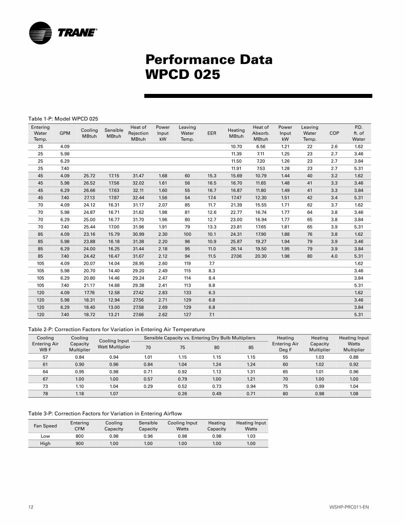
Table 1-P: Model WPCD 025
Entering Water Temp.
GPMCooling MBtuh
Sensible MBtuh
Heat of Rejection
MBtuh
Power Input kW
Leaving Water Temp.
EERHeating MBtuh
Heat of Absorb. MBtuh
Power Input kW
Leaving Water Temp.
COPP.D. ft. of
Water
25 4.09 10.70 6.56 1.21 22 2.6 1.62
25 5.98 11.39 7.11 1.25 23 2.7 3.46
25 6.29 11.50 7.20 1.26 23 2.7 3.84
25 7.40 11.91 7.53 1.28 23 2.7 5.31
45 4.09 25.72 17.15 31.47 1.68 60 15.3 15.69 10.79 1.44 40 3.2 1.62
45 5.98 26.52 17.56 32.02 1.61 56 16.5 16.70 11.65 1.48 41 3.3 3.46
45 6.29 26.66 17.63 32.11 1.60 55 16.7 16.87 11.80 1.49 41 3.3 3.84
45 7.40 27.13 17.87 32.44 1.56 54 17.4 17.47 12.30 1.51 42 3.4 5.31
70 4.09 24.12 16.31 31.17 2.07 85 11.7 21.39 15.55 1.71 62 3.7 1.62
70 5.98 24.87 16.71 31.62 1.98 81 12.6 22.77 16.74 1.77 64 3.8 3.46
70 6.29 25.00 16.77 31.70 1.96 80 12.7 23.00 16.94 1.77 65 3.8 3.84
70 7.40 25.44 17.00 31.96 1.91 79 13.3 23.81 17.65 1.81 65 3.9 5.31
85 4.09 23.16 15.79 30.99 2.30 100 10.1 24.31 17.90 1.88 76 3.8 1.62
85 5.98 23.88 16.18 31.38 2.20 96 10.9 25.87 19.27 1.94 79 3.9 3.46
85 6.29 24.00 16.25 31.44 2.18 95 11.0 26.14 19.50 1.95 79 3.9 3.84
85 7.40 24.42 16.47 31.67 2.12 94 11.5 27.06 20.30 1.98 80 4.0 5.31
105 4.09 20.07 14.04 28.95 2.60 119 7.7 1.62
105 5.98 20.70 14.40 29.20 2.49 115 8.3 3.46
105 6.29 20.80 14.46 29.24 2.47 114 8.4 3.84
105 7.40 21.17 14.68 29.38 2.41 113 8.8 5.31
120 4.09 17.76 12.58 27.42 2.83 133 6.3 1.62
120 5.98 18.31 12.94 27.56 2.71 129 6.8 3.46
120 6.29 18.40 13.00 27.58 2.69 129 6.8 3.84
120 7.40 18.72 13.21 27.66 2.62 127 7.1 5.31
Table 2-P: Correction Factors for Variation in Entering Air Temperature
Cooling Entering Air
WB F
Cooling Capacity Multiplier
Cooling Input Watt Multiplier
Sensible Capacity vs. Entering Dry Bulb Multipliers Heating Entering Air
Deg F
Heating Capacity Multiplier
Heating Input Watts
Multiplier70 75 80 85
57 0.84 0.94 1.01 1.15 1.15 1.15 55 1.03 0.88
61 0.90 0.96 0.84 1.04 1.24 1.24 60 1.02 0.92
64 0.95 0.98 0.71 0.92 1.13 1.31 65 1.01 0.96
67 1.00 1.00 0.57 0.79 1.00 1.21 70 1.00 1.00
73 1.10 1.04 0.29 0.52 0.73 0.94 75 0.99 1.04
78 1.18 1.07 0.26 0.49 0.71 80 0.98 1.08
Table 3-P: Correction Factors for Variation in Entering Airflow
Fan SpeedEntering
CFMCooling Capacity
Sensible Capacity
Cooling Input Watts
HeatingCapacity
Heating Input Watts
Low 800 0.98 0.96 0.98 0.98 1.03
High 900 1.00 1.00 1.00 1.00 1.00
Performance DataWPCD 025

WSHP-PRC011-EN 13
Performance DataWPCD 031
Table 4-P: Model WPCD 031
Entering Water Temp.
GPMCooling MBtuh
Sensible MBtuh
Heat of Rejection
MBtuh
Power Input kW
Leaving Water Temp.
EERHeating MBtuh
Heat of Absorb. MBtuh
Power Input kW
Leaving Water Temp.
COPP.D. ft. of
Water
25 5.12 17.21 10.54 1.95 21 2.6 2.54
25 7.48 18.32 11.44 2.02 22 2.7 5.42
25 7.87 18.50 11.59 2.03 22 2.7 6.01
25 9.26 19.16 12.12 2.06 22 2.7 8.32
45 5.12 32.16 20.36 39.34 2.10 60 15.3 25.25 17.37 2.31 38 3.2 2.54
45 7.48 33.16 20.85 40.03 2.01 56 16.5 26.88 18.75 2.38 40 3.3 5.42
45 7.87 33.32 20.93 40.15 2.00 55 16.7 27.15 18.98 2.39 40 3.3 6.01
45 9.26 33.91 21.21 40.55 1.95 54 17.4 28.11 19.80 2.44 41 3.4 8.32
70 5.12 30.15 19.38 38.97 2.58 85 11.7 34.41 25.01 2.75 60 3.7 2.54
70 7.48 31.09 19.84 39.53 2.47 81 12.6 36.63 26.94 2.84 63 3.8 5.42
70 7.87 31.25 19.92 39.62 2.45 80 12.7 37.00 27.26 2.85 63 3.8 6.01
70 9.26 31.80 20.19 39.95 2.39 79 13.3 38.31 28.40 2.90 64 3.9 8.32
85 5.12 28.95 18.79 38.74 2.87 100 10.1 39.11 28.80 3.02 74 3.8 2.54
85 7.48 29.85 19.23 39.23 2.75 95 10.9 41.63 31.00 3.11 77 3.9 5.42
85 7.87 30.00 19.31 39.31 2.73 95 11.0 42.05 31.37 3.13 77 3.9 6.01
85 9.26 30.53 19.57 39.59 2.65 94 11.5 43.54 32.67 3.19 78 4.0 8.32
105 5.12 25.09 16.82 36.19 3.25 119 7.7 2.54
105 7.48 25.87 17.23 36.49 3.11 115 8.3 5.42
105 7.87 26.00 17.30 36.55 3.09 114 8.4 6.01
105 9.26 26.46 17.53 36.73 3.01 113 8.8 8.32
120 5.12 22.20 15.26 34.27 3.54 133 6.3 2.54
120 7.48 22.89 15.64 34.45 3.39 129 6.8 5.42
120 7.87 23.00 15.71 34.48 3.36 129 6.8 6.01
120 9.26 23.41 15.93 34.58 3.27 127 7.1 8.32
Table 5-P: Correction Factors for Variation in Entering Air Temperature
Cooling Entering Air
WB F
Cooling Capacity Multiplier
Cooling Input Watt Multiplier
Sensible Capacity vs. Entering Dry Bulb Multipliers Heating Entering Air
Deg F
Heating Capacity Multiplier
Heating Input Watts
Multiplier70 75 80 85
57 0.84 0.94 1.01 1.15 1.15 1.15 55 1.03 0.88
61 0.90 0.96 0.84 1.04 1.24 1.24 60 1.02 0.92
64 0.95 0.98 0.71 0.92 1.13 1.31 65 1.01 0.96
67 1.00 1.00 0.57 0.79 1.00 1.21 70 1.00 1.00
73 1.10 1.04 0.29 0.52 0.73 0.94 75 0.99 1.04
78 1.18 1.07 0.26 0.49 0.71 80 0.98 1.08
Table 6-P: Correction Factors for Variation in Entering Airflow
Fan SpeedEntering
CFMCooling Capacity
Sensible Capacity
Cooling Input Watts
HeatingCapacity
Heating Input Watts
Low 800 0.98 0.96 0.98 0.98 1.03
High 900 1.00 1.00 1.00 1.00 1.00
14 WSHP-PRC011-EN
Performance DataWPCD 036
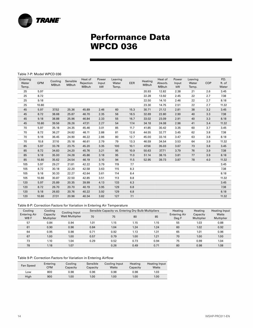
Table 7-P: Model WPCD 036
Entering Water Temp.
GPMCooling MBtuh
Sensible MBtuh
Heat of Rejection
MBtuh
Power Input kW
Leaving Water Temp.
EERHeating MBtuh
Heat of Absorb. MBtuh
Power Input kW
Leaving Water Temp.
COPP.D. ft. of
Water
25 5.97 20.93 12.82 2.38 21 2.6 3.45
25 8.72 22.28 13.92 2.45 22 2.7 7.38
25 9.18 22.50 14.10 2.46 22 2.7 8.18
25 10.80 23.30 14.75 2.51 22 2.7 11.32
45 5.97 37.52 25.36 45.89 2.46 60 15.3 30.71 21.12 2.81 38 3.2 3.45
45 8.72 38.68 25.87 46.70 2.35 56 16.5 32.69 22.80 2.90 40 3.3 7.38
45 9.18 38.88 25.96 46.84 2.33 55 16.7 33.02 23.09 2.91 40 3.3 8.18
45 10.80 39.56 26.26 47.31 2.27 54 17.4 34.18 24.08 2.96 41 3.4 11.32
70 5.97 35.18 24.35 45.46 3.01 85 11.7 41.85 30.42 3.35 60 3.7 3.45
70 8.72 36.27 24.82 46.11 2.88 81 12.6 44.55 32.77 3.45 62 3.8 7.38
70 9.18 36.45 24.90 46.22 2.86 80 12.7 45.00 33.16 3.47 63 3.8 8.18
70 10.8 37.10 25.18 46.61 2.79 79 13.3 46.59 34.54 3.53 64 3.9 11.32
85 5.97 33.78 23.75 45.20 3.35 100 10.1 47.56 35.03 3.67 73 3.8 3.45
85 8.72 34.83 24.20 45.76 3.21 95 10.9 50.63 37.71 3.79 76 3.9 7.38
85 9.18 35.00 24.28 45.86 3.18 95 11.0 51.14 38.15 3.81 77 3.9 8.18
85 10.80 35.62 24.54 46.19 3.10 94 11.5 52.95 39.73 3.87 78 4.0 11.32
105 5.97 29.27 21.81 42.22 3.79 119 7.7 3.45
105 8.72 30.18 22.20 42.58 3.63 115 8.3 7.38
105 9.18 30.33 22.27 42.64 3.61 114 8.4 8.18
105 10.80 30.87 22.50 42.85 3.51 113 8.8 11.32
120 5.97 25.89 20.35 39.99 4.13 133 6.3 3.45
120 8.72 26.70 20.70 40.19 3.95 129 6.8 7.38
120 9.18 26.83 20.76 40.22 3.92 129 6.8 8.18
120 10.80 27.31 20.96 40.34 3.82 127 7.1 11.32
Table 8-P: Correction Factors for Variation in Entering Air Temperature
Cooling Entering Air
WB F
Cooling Capacity Multiplier
Cooling Input Watt Multiplier
Sensible Capacity vs. Entering Dry Bulb Multipliers Heating Entering Air
Deg F
Heating Capacity Multiplier
Heating Input Watts
Multiplier70 75 80 85
57 0.84 0.94 1.01 1.15 1.15 1.15 55 1.03 0.88
61 0.90 0.96 0.84 1.04 1.24 1.24 60 1.02 0.92
64 0.95 0.98 0.71 0.92 1.13 1.31 65 1.01 0.96
67 1.00 1.00 0.57 0.79 1.00 1.21 70 1.00 1.00
73 1.10 1.04 0.29 0.52 0.73 0.94 75 0.99 1.04
78 1.18 1.07 0.26 0.49 0.71 80 0.98 1.08
Table 9-P: Correction Factors for Variation in Entering Airflow
Fan SpeedEntering
CFMCooling Capacity
Sensible Capacity
Cooling Input Watts
HeatingCapacity
Heating Input Watts
Low 800 0.98 0.96 0.98 0.98 1.03
High 900 1.00 1.00 1.00 1.00 1.00
WSHP-PRC011-EN 15
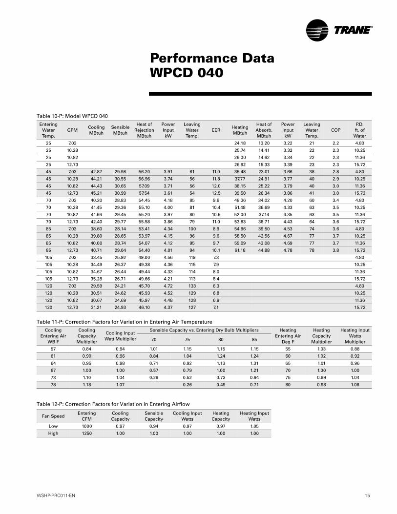
Performance DataWPCD 040
Table 10-P: Model WPCD 040
Entering Water Temp.
GPMCooling MBtuh
Sensible MBtuh
Heat of Rejection
MBtuh
Power Input kW
Leaving Water Temp.
EERHeating MBtuh
Heat of Absorb. MBtuh
Power Input kW
Leaving Water Temp.
COPP.D. ft. of
Water
25 7.03 24.18 13.20 3.22 21 2.2 4.80
25 10.28 25.74 14.41 3.32 22 2.3 10.25
25 10.82 26.00 14.62 3.34 22 2.3 11.36
25 12.73 26.92 15.33 3.39 23 2.3 15.72
45 7.03 42.87 29.98 56.20 3.91 61 11.0 35.48 23.01 3.66 38 2.8 4.80
45 10.28 44.21 30.55 56.96 3.74 56 11.8 37.77 24.91 3.77 40 2.9 10.25
45 10.82 44.43 30.65 57.09 3.71 56 12.0 38.15 25.22 3.79 40 3.0 11.36
45 12.73 45.21 30.99 57.54 3.61 54 12.5 39.50 26.34 3.86 41 3.0 15.72
70 7.03 40.20 28.83 54.45 4.18 85 9.6 48.36 34.02 4.20 60 3.4 4.80
70 10.28 41.45 29.36 55.10 4.00 81 10.4 51.48 36.69 4.33 63 3.5 10.25
70 10.82 41.66 29.45 55.20 3.97 80 10.5 52.00 37.14 4.35 63 3.5 11.36
70 12.73 42.40 29.77 55.58 3.86 79 11.0 53.83 38.71 4.43 64 3.6 15.72
85 7.03 38.60 28.14 53.41 4.34 100 8.9 54.96 39.50 4.53 74 3.6 4.80
85 10.28 39.80 28.65 53.97 4.15 96 9.6 58.50 42.56 4.67 77 3.7 10.25
85 10.82 40.00 28.74 54.07 4.12 95 9.7 59.09 43.08 4.69 77 3.7 11.36
85 12.73 40.71 29.04 54.40 4.01 94 10.1 61.18 44.88 4.78 78 3.8 15.72
105 7.03 33.45 25.92 49.00 4.56 119 7.3 4.80
105 10.28 34.49 26.37 49.38 4.36 115 7.9 10.25
105 10.82 34.67 26.44 49.44 4.33 114 8.0 11.36
105 12.73 35.28 26.71 49.66 4.21 113 8.4 15.72
120 7.03 29.59 24.21 45.70 4.72 133 6.3 4.80
120 10.28 30.51 24.62 45.93 4.52 129 6.8 10.25
120 10.82 30.67 24.69 45.97 4.48 128 6.8 11.36
120 12.73 31.21 24.93 46.10 4.37 127 7.1 15.72
Table 11-P: Correction Factors for Variation in Entering Air Temperature
Cooling Entering Air
WB F
Cooling Capacity Multiplier
Cooling Input Watt Multiplier
Sensible Capacity vs. Entering Dry Bulb Multipliers Heating Entering Air
Deg F
Heating Capacity Multiplier
Heating Input Watts
Multiplier70 75 80 85
57 0.84 0.94 1.01 1.15 1.15 1.15 55 1.03 0.88
61 0.90 0.96 0.84 1.04 1.24 1.24 60 1.02 0.92
64 0.95 0.98 0.71 0.92 1.13 1.31 65 1.01 0.96
67 1.00 1.00 0.57 0.79 1.00 1.21 70 1.00 1.00
73 1.10 1.04 0.29 0.52 0.73 0.94 75 0.99 1.04
78 1.18 1.07 0.26 0.49 0.71 80 0.98 1.08
Table 12-P: Correction Factors for Variation in Entering Airflow
Fan SpeedEntering
CFMCooling Capacity
Sensible Capacity
Cooling Input Watts
HeatingCapacity
Heating Input Watts
Low 1000 0.97 0.94 0.97 0.97 1.05
High 1250 1.00 1.00 1.00 1.00 1.00

16 WSHP-PRC011-EN
Performance DataWPCD 045
Table 13-P: Model WPCD 045
Entering Water Temp.
GPMCooling MBtuh
Sensible MBtuh
Heat of Rejection
MBtuh
Power Input kW
Leaving Water Temp.
EERHeating MBtuh
Heat of Absorb. MBtuh
Power Input kW
Leaving Water Temp.
COPP.D. ft. of
Water
25 7.96 28.36 15.48 3.78 21 2.2 6.14
25 11.63 30.19 16.91 3.89 22 2.3 13.12
25 12.24 30.50 17.15 3.91 22 2.3 14.54
25 14.40 31.58 17.99 3.98 23 2.3 20.12
45 7.96 48.23 32.20 63.54 4.49 61 10.8 41.62 26.99 4.29 38 2.8 6.14
45 11.63 49.73 32.86 64.39 4.29 56 11.6 44.31 29.22 4.42 40 2.9 13.12
45 12.24 49.98 32.96 64.53 4.26 56 11.7 44.75 29.59 4.44 40 3.0 14.54
45 14.40 50.86 33.35 65.02 4.15 54 12.3 46.33 30.90 4.52 41 3.0 20.12
70 7.96 45.23 30.90 61.60 4.80 85 9.4 56.73 39.91 4.93 60 3.4 6.14
70 11.63 46.63 31.51 62.31 4.59 81 10.2 60.39 43.04 5.08 63 3.5 13.12
70 12.24 46.87 31.61 62.42 4.56 80 10.3 61.00 43.57 5.11 63 3.5 14.54
70 14.40 47.70 31.97 62.84 4.44 79 10.7 63.15 45.41 5.20 64 3.6 20.12
85 7.96 43.43 30.12 60.43 4.99 100 8.7 64.47 46.34 5.31 73 3.6 6.14
85 11.63 44.78 30.70 61.06 4.77 96 9.4 68.63 49.93 5.48 76 3.7 13.12
85 12.24 45.00 30.80 61.16 4.74 95 9.5 69.32 50.53 5.51 77 3.7 14.54
85 14.40 45.79 31.14 61.53 4.61 94 9.9 71.77 52.65 5.60 78 3.8 20.12
105 7.96 37.64 27.64 55.49 5.23 119 7.2 6.14
105 11.63 38.81 28.14 55.90 5.01 115 7.7 13.12
105 12.24 39.00 28.23 55.97 4.97 114 7.8 14.54
105 14.40 39.69 28.52 56.21 4.84 113 8.2 20.12
120 7.96 33.29 25.77 51.79 5.42 133 6.1 6.14
120 11.63 34.33 26.22 52.03 5.19 129 6.6 13.12
120 12.24 34.50 26.29 52.07 5.15 129 6.7 14.54
120 14.40 35.11 26.55 52.22 5.01 127 7.0 20.12
Table 14-P: Correction Factors for Variation in Entering Air Temperature
Cooling Entering Air
WB F
Cooling Capacity Multiplier
Cooling Input Watt Multiplier
Sensible Capacity vs. Entering Dry Bulb Multipliers Heating Entering Air
Deg F
Heating Capacity Multiplier
Heating Input Watts
Multiplier70 75 80 85
57 0.84 0.94 1.01 1.15 1.15 1.15 55 1.02 0.90
61 0.90 0.96 0.84 1.04 1.24 1.24 60 1.02 0.94
64 0.95 0.98 0.71 0.92 1.13 1.31 65 1.01 0.97
67 1.00 1.00 0.57 0.79 1.00 1.21 70 1.00 1.00
73 1.10 1.04 0.29 0.52 0.73 0.94 75 0.99 1.03
78 1.18 1.07 0.26 0.49 0.71 80 0.99 1.07
Table 15-P: Correction Factors for Variation in Entering Airflow
Fan SpeedEntering
CFMCooling Capacity
Sensible Capacity
Cooling Input Watts
HeatingCapacity
Heating Input Watts
Low 1000 0.97 0.94 0.97 0.97 1.04
High 1250 1.00 1.00 1.00 1.00 1.00

WSHP-PRC011-EN 17
Table E-1: Electrical performance for standard blower motorModel No.
WPCDVolts Total
FLAComp.
RLAComp.
LRANo. of
Compres.BlowerMotorFLA
BlowerMotor
HP
BlowerMotorQty.
Min.Circ.
Ampacity
OvercurrentProtective Device
(AMPS)025 208-230/60/1 10.6 8.1 49.0 1 2.5 1/3 1 12.6 20
208-230/60/3 9.1 6.6 50.0 2.5 10.8 15460/60/3 4.7 3.4 25.0 1.3 5.6 15
031 208/230/60/1 14.8 12.3 71.0 1 2.5 1/3 1 17.9 30208-230/60/3 10.9 8.4 71.0 2.5 13.0 20
460/60/3 5.4 4.1 36.0 1.3 6.4 15036 208-230/60/1 17.0 14.5 78.0 1 2.5 1/3 1 20.6 35
208-230/60/3 11.4 8.9 59.9 2.5 13.6 20460/60/3 5.7 4.4 30.7 1.3 6.7 15
040 208/230/60/1 21.3 19.7 108.0 1 0.8 1/10 2 26.2 45208-230/60/3 13.6 12.0 74.0 0.5 16.6 25
460/60/3 7.0 6.0 37.0 0.5 8.5 15045 208-230/60/1 23.1 21.5 116.0 1 0.8 1/10 2 28.5 45
208-230/60/3 14.9 13.3 93.0 0.8 18.2 30460/60/3 7.5 6.5 46.0 0.5 9.1 15
Performance DataElectrical

18 WSHP-PRC011-EN
Performance DataAntifreeze Correction Factors
Table A1: Correction Factors for AntifreezeSolutions
Methanol
ItemConcentration by Volume
10% 20% 30% 40% 50%Cool
Capacity.9980 .9965 .9949 .9932 .9915
HeatCapacity
.9950 .9898 .9846 .9794 .9742
PressureDrop
1.023 1.057 1.091 1.122 1.160
Ethylene GlycolCool
Capacity.9955 .9912 .9870 .9830 .9790
HeatCapacity
.9925 .9848 .9770 .9690 .9610
PressureDrop
1.024 1.068 1.124 1.188 1.263
Propylene GlycolCool
Capacity.9934 .9869 .9804 .9739 .9681
HeatCapacity
.9863 .9732 .9603 .9477 .9350
PressureDrop
1.040 1.098 1.174 1.273 1.405
Example 1 (Ethylene Glycol):The antifreeze solution is 20% by volume of Ethylene Glycol. Determine the corrected cooling capacity and waterside pressure drop for a WPCD 025 when the EWT is 85 F and the GPM is 6.29.
From the catalog data, the cooling capacity at these conditions with 100% water is 24.00 MBTUH, and the waterside pressure drop is 3.84 feet of head. At 20% Ethylene Glycol, the correction factor for cool capacity is 0.9912 and the pressure drop is 1.068.
The corrected cooling capacity (MBTUH) = 24.00 * 0.9912 = 23.79. The corrected water side pressure drop (Ft. head) = 3.84 * 1.068 = 4.10.
Example 2 (Propylene Glycol):The antifreeze solution is 30% by volume of Propylene Glycol. Determine the corrected heating capacity and waterside pressure drop for a WPCD 025 when the EWT is 45 F and the GPM is 6.29.
From the catalog data, the heating capacity at these conditions with 100% water is 16.87 MBTUH, and the waterside pres-sure drop is 3.84 feet of head. At 30% Propylene Glycol, the correction factor for heat capacity is 0.9603 and the pressure drop is 1.174.
The corrected heating capacity (MBTUH) = 16.87 * 0.9603 = 16.20. The corrected water side pressure drop (Ft. head) = 3.84 * 1.174 = 4.51.

WSHP-PRC011-EN 19
Control WiringUnit Mtd Auto Changeover

20 WSHP-PRC011-EN
Control Wiring24 Volt Wall Mtd T’stat
WSHP-PRC011-EN 21
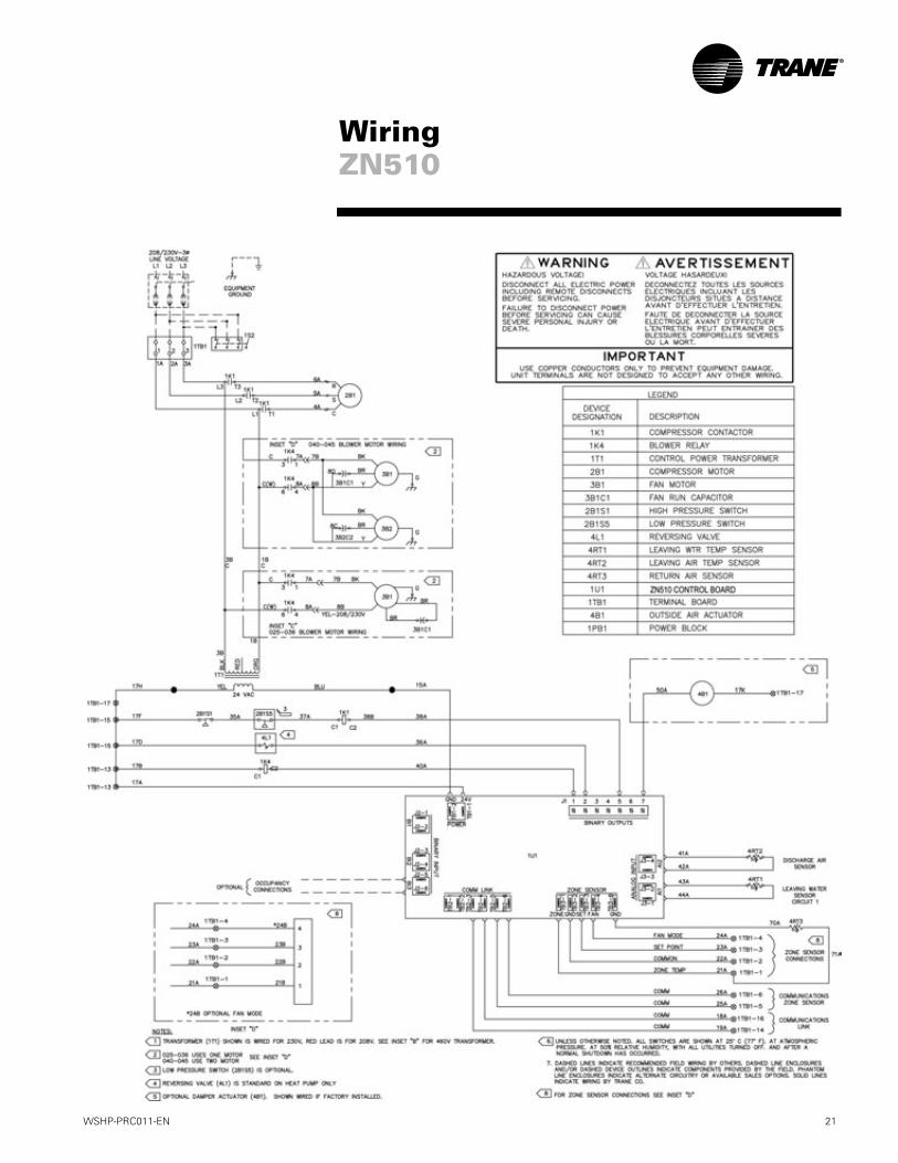
WiringZN510

22 WSHP-PRC011-EN
Dimensional Data025 to 036 - Left Hand Piping

WSHP-PRC011-EN 23
Dimensional Data025 to 036 - Right Hand Piping

24 WSHP-PRC011-EN
Dimensional Data025 to 036 - Left Hand Piping
Sloped-Top

WSHP-PRC011-EN 25
Dimensional Data025 to 036 - Right Hand Piping
Sloped-Top

26 WSHP-PRC011-EN
Dimensional Data040 & 045 - Left Hand Piping

WSHP-PRC011-EN 27
Dimensional Data040 & 045 - Right Hand Piping
28 WSHP-PRC011-EN
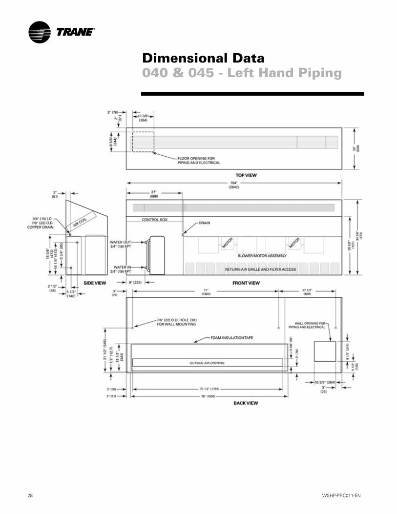
Dimensional Data040 & 045 - Left Hand Piping
WSHP-PRC011-EN 29
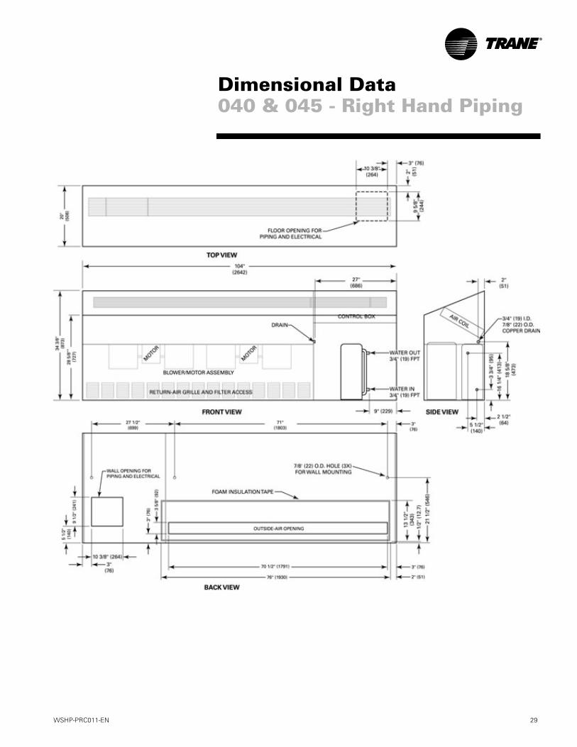
Dimensional Data040 & 045 - Right Hand Piping

30 WSHP-PRC011-EN
Thermostat/Sensor LocationLocation of the thermostat or zone sensor is an important element of effective room control and comfort.
The best location is typically on a wall, remote from the HVAC unit’s supply/return-air grille. Readings at this location assure that the desired setpoint is achieved across the space not just near the unit itself. It may be necessary to subdivide the zone to ensure adequate control and comfort is accomplished.
Thermostats/Zone Sensors
Thermostat/Sensor Part Number/Description Description
X13510589010 - thermostatX13530655010 - subbase
Manual ChangeoverThermostat (Mercury)
• 1-stage heat/1-stage cool with HEAT-OFF-COOL
• Non programmable• Fan switching includes ON-AUTO• Adjustable dead band
X13510598010 - thermostatX13530070010 - subbase
Auto ChangeoverThermostat (Mercury)
• 1-stage heat/1-stage cool/ with AUTO-OFF
• Non programmable• Fan switching includes ON-AUTO• Adjustable dead band
X13510309010 - thermostatX13530069020 - subbase
Mercury Thermostat
• 1-stage heat/1-stage cool with HEAT-OFF-COOL
• Non programmable• Fan switching includes
FAN ON-AUTO
X13510599010 - thermostatX13530070010 - subbase
Auto ChangeoverThermostat (Mercury)
• 1-stage heat/1-stage cool/1-stage cooling changeover with AUTO-OFF
• Non programmable• Fan switching includes
ON-AUTO• 12-degree night setback
Accessories

WSHP-PRC011-EN 31
Thermostat/Sensor Part Number Description
X13510599010 - thermostatX13530066010 - subbase
Auto ChangeoverThermostat (Mercury)
• 2-stage heat/1-stage cool/1-stage cooling changeover with AUTO-OFF
• Non programmable• Fan switching includes ON-AUTO• 12-degree night setback• 2-LEDs (light emitting diodes)
X13510575010 Manual ChangeoverThermostat (Mercury)
• 1-stage heat/1-stage cool with HEAT-OFF-COOL
• Non programmable• Fan switching includes ON-AUTO
X13510586010 - thermostatX13530053010 - subbase
Auto ChangeoverThermostat (Digital)
• 2-stage heat/1-stage cool with AUTO-COOL-OFF-HEAT-EM HT
• Fan switching includes ON-AUTO
• 7-Day programmable• 2-LEDs (light emitting diodes)• 2-Occupied/2-Unoccupied
X13510587010 Auto ChangeoverThermostat (Digital)
• 1-stage heat/1-stage cool with auto changeover
• 7-Day programmable• 12-degree night setback• 2-Occupied/2-Unoccupied
X13510635010 Zone Sensor
• TUC compatible• External setpoint adjustment
wheel• Communication Jack• ON and CANCEL buttons• Fan switch COOL-AUTO-OFF-
HEAT
Accessories
32 WSHP-PRC011-EN
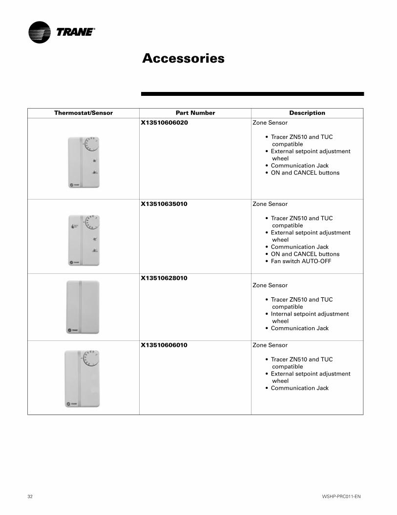
Thermostat/Sensor Part Number Description
X13510606020 Zone Sensor
• Tracer ZN510 and TUC compatible
• External setpoint adjustment wheel
• Communication Jack• ON and CANCEL buttons
X13510635010 Zone Sensor
• Tracer ZN510 and TUC compatible
• External setpoint adjustment wheel
• Communication Jack• ON and CANCEL buttons• Fan switch AUTO-OFF
X13510628010Zone Sensor
• Tracer ZN510 and TUC compatible
• Internal setpoint adjustment wheel
• Communication Jack
X13510606010 Zone Sensor
• Tracer ZN510 and TUC compatible
• External setpoint adjustment wheel
• Communication Jack
Accessories

WSHP-PRC011-EN 33
Water Regulating Valve AssemblyThe water regulating valve assembly consists of a direct acting valve and a reverse acting valve installed on the water-out side of the unit. The direct acting vales opens in response to an increase in discharge pressure during the cooling cycle. The reverse acting valve opens in response to a decrease in suction pressure during the heating cycle. Water regulating valves should be used where low flow and low or high fluid temperature conditions could occur. This option is beneficial with open loop systems, but not nec-essary. See Figure 6 for water regulat-ing valve assembly.
Figure 6: Water regulating valve
Hose KitsTrane provides three hose kit selec-tions for equipment balancing.
• Ball valve flow control (manual)
• Circuit setter flow control(manual)
• Automatic flow control(automatic)
Each selection provides some accura-cy in equipment balancing. Range of accuracy consist of ±25% for the ball valve method, ±20% for the circuit set-ter method, and ±10% for the automat-ic flow control method.
Utilizing the ball valve method, the pressure/temperature measurement on the leaving and entering side of the heat pump is measure within the wa-ter piping. The ball valve is then throt-
tled to change the amount of flow to the unit to reach the desired tempera-ture or pressure differential.
The circuit setter method combines both the readout and the adjustment feature in one device. In order to deter-mine flow rate, the user must record both handle position, and differential pressure drop. Then, the user must consult a chart containing both pieces of information to make the necessary adjustments to the circuit setter.
For automatic system balancing of a water-source heat pump, the Mesurflo® self balancing kit provides a constant flow rate over the pressure differential rage of 2 to 80 psid. As sys-tem pressure change (through further addition of heat pumps, for example) each individual flow control valve will automatically adjust to the new sys-tem conditions. In variable water vol-ume applications, a self balancing hose kit can provide continuous bal-ancing because of its ability to auto-matically adjust to the varying system conditions. For more information per-taining to the automatic balancing hose kits, see literature documenta-tion WSHP-SLB005-EN. See Figure 7 for the Mesurflo automatic hose kit.
Figure 7: Mesurflo hose kit
Tracer Loop ControllerTrane’s Tracer Loop Controller (TLC) is a cost effective way of controlling the WSHP equipment, as well as the me-chanical components powered by the WSHP. Fluid Coolers, boilers and pumps may be connected and con-trolled by the loop controller for total system optimization. See Figure 8.
Figure 8: Tracer loop control panel
The Tracer loop control panel has the ability to lower or raise the water loop temperature during low energy use hours (typically during the nighttime hours) to provide a greater optimiza-tion during the time of day where en-ergy consumption may be at it’s greatest. Using the loop controller as a means of coordinating cooling or heating storage, the building owner can expect better efficiencies from the WSHP equipment.
Accessories

34 WSHP-PRC011-EN
GeneralEquipment shall be completely assem-bled, piped, internally wired and test operated at the factory. The equipment shall contain an ETL listing and label prior to leaving the factory. Canadian units shall be CETL certified. Service and caution area la-bels shall also be placed on the unit in their appropriate locations.
CasingSteel surfaces shall cleaned, phos-phatized, rinsed and dried before ap-plication of final finish coat. The final finish shall be an appliance grade fin-ish. It shall be applied by an electro-static powder spray system, minimum thickness of 1 mil with no visible run marks. Units shall be available in one of five decorator colors as selected by the architect.
The insulation shall contain a flame spread rating of less than 25 and smoke density rating of less than 50 (as tested in accordance with ASTM-85). The elastomeric insulation has a UL 94V-5 rating. All insulation edges shall be either captured or sealed.
A removable front panel shall be held into place by concealed fasteners. The discharge-air grille shall be rigid in de-sign with vanes angled at 15º to deflect the discharged, supply-air into the room. This extruded bar type grille shall be hinged on the back over the control section to permit access to equipment encompassing unit mount-ed controls.
FiltersOne inch, throwaway filters shall be standard and factory installed. The fil-ters shall have an average resistance of 76-percent and dust holding capaci-ty of 26-grams per square foot.
CompressorsAll shall have direct-drive, hermetic, reciprocating type compressors. A rubber mounting device located un-derneath the mounting base of the compressor shall provide external vi-bration isolation.
Internal thermal overload protection shall also be provided. Protection against excessive discharge pressure shall be provided by means of a high pressure switch. A loss of charge shall be provided by a selectable low pres-sure switch.Refrigerant CircuitsThe refrigerant circuit shall contained a fixed orifice or thermal expansion device, service pressure ports, and re-frigerant line filter driers factory-in-stalled as standard.Air-to-Refrigerant CoilInternally finned, 3/8-inch copper tubes mechanically bonded to a con-figured aluminum plate fin shall be standard. Coils shall be leak tested at the factory to ensure the pressure in-tegrity. The coil shall be leak tested to 200 psig and pressure tested to 450 psig.Drain PanThe condensate pan shall be con-structed of galvanized steel with weld-ed, coated corners and copper nipple shall be provided for condensate con-nections. A clear drain hose shall be factory clamped onto the drain con-nection for field hook-up.
Water-to-Refrigerant Heat ExchangerThe water-to-refrigerant heat ex-changer shall be of a high quality coil-in-shell design. The copper or optional cupro-nickel coil shall be deeply fluted to enhance heat transfer and minimize fouling and scaling. The coil shall have a working pressure of 450 psig on both the refrigerant and water sides.
Indoor FanThree-phase units shall offer a belt driven, FC, centrifugal fan with adjust-able motor sheaves. All motors shall be thermally protected. Oversized mo-tors shall be available for high static applications. All indoor fan motors shall meet the U.S. Energy Policy Act of 1992 (EPACT).
ControlsThe unit control box shall contain all necessary devices to allow heating and cooling operation to occur from a remote wall or unit mounted thermo-stat. These devices shall be as follows:
• 24 VAC energy limiting class II 50 VA breaker type transformer
• 24 VAC blower motor relay
• 24 VAC compressor contactor
• Fluid thermostat connections shall be provided for ease of hook-up to a terminal strip located in the unit’s control box
• The low-water temperature switch or freezestat shall protect the wa-ter-to-refrigerant heat exchanger from freezing. This device shall prevent the compressor operation with leaving water temperatures below 35ºF (2ºC). An optional low-water temperature switch shall be applied for low temperature or geothermal applications, where an appropriate antifreeze solution is used.
• Lockout relay which controls cy-cling of the compressor shall be provided to protect the compres-sor during adverse operating con-ditions. The device may be reset by interrupting power to the 24 VAC control circuit. Reset may be done either at a remote thermostat or through a momentary main power interruption
Nameplate information shall be pro-vided for the application of either time-delay fuses or HACR circuit breakers for branch circuit protection from the primary source of power.
Mechanical Specifications

WSHP-PRC011-EN 35
Unit Mounted Manual Changeover Controls (option)The unit mounted manual changeover control package (UT1) shall contain a high pressure switch, compressor lockout relay for control protection, and leaving water temperature freez-estat. The unit’s manual thermostat shall contain a COOL-OFF-HEAT man-ual selection buttons, with 2-speed fan switch between HIGH and LOW. High voltage power connections shall be made at the unit’s power block.
Unit Mounted Auto Changeover Controls (option)The unit mounted auto changeover control package (UT3) shall contain a high pressure switch, compressor lockout relay for control protection, and leaving water temperature freez-estat. The unit’s auto thermostat shall contain a COOL-OFF-HEAT-AUTO se-lection buttons, with 2-speed fan switch between HIGH and LOW. High voltage power connections shall be made at the unit’s power block.
Wall Mounted Thermostat for 24 Volt Controls (option)The wall mounted manual/auto changeover control package (LVS) shall contain a high pressure switch, compressor lockout relay for control protection, and leaving water temper-ature freezestat. The unit’s 24 volt ther-mostat selection contain a terminal strip capable of connecting to a manu-al or automatic changeover thermo-stat. The LVS control package shall be capable of establishing communica-tion as a standalone unit to thermostat connection, or as a multiple unit (mas-ter/slave set-up) to thermostat connec-tion., with 2-speed fan switch between HIGH and LOW. High voltage power connections shall be made at the unit’s power block.
Optional Relays Optional relays for additional mechan-ical controls such as random start-up, 3-minute time delay, night setback and morning warm-up options shall be of-fered with the 24 volt control packag-
es. Each device shall be factory mounted, wired and tested in the equipment.
Tracer ZN510 Controls (special design option)This system shall utilize factory fur-nished and mounted DDC controls for operation of up to 120 units on a COMM5 (LonTalk) link. The Tracer ZN510 control package shall include random start delay, heating/cooling status, occupied/unoccupied mode, fan status and filter maintenance op-tions. Three LEDs (light emitting di-odes) shall be included for diagnostics of the equipment in the event that sys-tem software is not available.
The ZN510 control package shall be LonTalk certified and capable of com-municating with other LonTalk certi-fied controllers. It shall be capable of a standalone application, or as applied to a Tracer Loop Control system, or as a full building automation installation.
Terminal Unit Controls (option)This system shall utilize factory fur-nished and mounted DDC controls for operation of a complete building sys-tem on a Comm 4 link. The TUC con-trol package shall include a 75 VAC transformer. The controller shall pro-vide anti-short cycle compressor pro-tection, random start, heating / cooling status, occupied / unoccupied mode, as well as fan and filter status options. Five LEDs (light emitting diodes) shall also be included for diagnostics of the equipment.
Water RegulatingValve Assembly (option)The water regulating valve assembly shall consist of a direct acting valve and a reverse acting valve. The direct acting valve shall open in response to an increase in discharge pressure dur-ing the cooling cycle. The reverse act-ing valve shall open in response to a decrease in suction pressure during the heating cycle. Water regulating valves shall be used where low flow, or low or high fluid temperature condi-
tions exist. This accessory shall be used with open-loop systems.
Ball Valves (option)Ball valves shall be field installed be-tween the unit and the loop pump module, on both supply and return lines to the loop.
Hoses (option)Hoses shall consist of a stainless steel outer braid with an inner core of tube made of a nontoxic synthetic polymer material. The hoses shall be suitable for water temperatures ranging be-tween 33 F and 211 F without the use of glycol.
Automatic Flow Devices (option)The automatic flow kit shall contain a Hays Mesurflo® automatic flow con-trol valve, two ball valves, two flexible hoses, a high flow Y-strainer, and may include a strainer blow-down and var-ious other accessories.
The automatic flow control valve shall be factory set to a rated flow, and shall automatically control the flow to with-in 10% of the rated value over a 40 to 1 differential pressure, operating range (2 to 80 PSID). Operational tempera-ture shall be rated from fluid freezing, to 225-degrees F. The valve body shall be constructed from hot forged brass UNS C37700 per ASTM B-283 latest re-vision. For more information pertain-ing to the automatic balancing hose kits, see literature documentation WSHP-SLB005-EN.
WarrantyThe unit shall be warranted by the manufacturer against defects for one year. The entire refrigerant circuit in-cluding motor-compressor, expansion device, all heat exchangers in contact with refrigerants, and reversing valve (less solenoid coil) shall be warranted for that year (parts only). Optional ex-tended warranties shall be made avail-able.
Mechanical Specifications

Since Trane has a policy of continuous product and data improvement, it reserves the right to change design and specifications without notice.
Literature Order Number WSHP-PRC011-EN
File Number PL-RF-WSHP-PRC011-10-02
Supersedes WSHP-DS-4, WSHP-CS-4B
Stocking Location Electronic OnlyTrane An American Standard Companywww.trane.com
For more information, contactyour local district office ore-mail us at [email protected]