stainless steel nfpa interchangeable cylinder line · stainless steel nfpa interchangeable cylinder...
TRANSCRIPT

S SeriesStainless Steel NFPA Interchangeable Cylinder Line
w w w . n u m a t i c s . c o m

S Series Features and Benefits 3 Standard Mounts 4 How to Order 5 Loading and Cushioning 6 Optional Features 7 Dimensions 8-14 Basic No-Mount 8 Rod Ends 9 Flange Mounts 10 Bottom Tap and Clevis Mount 11 Extended Tie Rod Mounts 12 Trunnion Mounts 13 Double Rod End 14 Accessories-Stainless Steel 15 Couplers 16 World Switches 17-18 NFPA Interchangeable Cylinders 18 Sensing Part Numbers 19-21 Quick Disconnect Cables 22 How to Order - S Series Piston Rod Assembly 23 How to Order - S Series Repair Kit 24 How to Order - S Series Seal Kit 24 Piston Rod Assembly Kit Removal/Installation Instructions 25 Repair and Seal Kit Removal/Installation Instructions 25 Diagrams 26 Seal Installation Guide 27
Table of Contents

Information subject to change without notice. For ordering information or regarding your local sales office visit www.numatics.com.3
SSERIES
Stainless Steel NFPA Interchangeable
TubeThe 316 stainless steel tube provides smooth, corrosion free operation.
End CapsThe end caps are accurately machined from precision 316 stainless steel blocks. Additionally, a recess on the piston-mating surface (at both ends) enables the air to work on a larger piston area for effortless breakaway.
Rod BushingThe S Series includes a cutting edge PolyLube™ composite rod bushing that is extra long in length. The composite rod bushing is specifi-cally designed for applications where corro-sion, low friction, and excellent wear charac-teristics are desired.
Rod SealThe carboxilated nitrile with PTFE compound rod seal is self-lubricating and durable. The rounded lip design ensures proper sealing and long life.
Rod WiperThe standard rod wiper construction is a highly durable polyurethane.
Piston RodThe piston rod is machined from 303 stainless steel and is turned, ground, polished, and has a chrome plated surface. This surface pro-vides maximum life for both the rod bushing and the seals.
Bushing RetainerThe bushing retainer is machined from highly corrosion resistant 304 stainless steel bar stock. Additionally, it is a full-face design. This is to minimize corners and crevices. It enables the cylinder to perform in food grade applications.
Tie RodsThe tie rods are drawn and ground 303 high strength stainless steel. The tie rod threads are rolled for superior strength and engagement. Furthermore, the tie rods are secured with 304 stainless steel acorn nuts. This eliminates exposed threads. Again, enabling the S Series cylinder to perform in food grade application.
Piston SealThe piston seal is a carboxilated nitrile with PTFE compound for self-lubrication. The “T” seal with back-up ring construction prevents rolling and seals at all pressures.
Wear BandThe wear band is a stable, lubricating strip located on the piston. We separated the load bearing points by locating the wear band at the rear of the piston. This maximizes column strength at full extension.
PistonThe solid aluminum alloy piston is strong and durable.
Cushion SealThe floating cushion seal design enables rapid stroke reversal by pro-viding instantaneous full flow to the piston. Each cushion has a flush, retained adjustment needle.
Tube End SealThe tube end seals are compression type and reusable.
PortsOur enhanced port design enables the cylinder to work more efficiently. Through the use of precise machining depths and tool shape, we are able to smooth the flow path into and out of the cylinder.
Standard Specifications:• Meets NFPA specifications• Bore sizes from 1-1/2” through 8”• Piston rod diameters from 5/8” to 1-3/4”• Maximum pressure rating is 150 psi air • Standard temperature -10°F to 165°F (-23°C to 74°C)• All stainless steel construction, except piston (aluminum)• NPTF ports• Flexible port and cushion location
The S Series is a stainless steel NFPA Interchangeable pneumatic cylinder line. It is designed and built to perform in the toughest “wash down” applications. The stainless steel construction provides outstanding corrosion resistance while including a multitude of favorable design features. The S Series encompasses many of the same proven design features as our original NFPA Interchangeable cylinder, the A Series. This includes an extra long bushing and a standard oversized wear band located on the rear of the piston. Additionally, we have also included the proven T Seal piston seal configuration with carboxilated nitrile with self-lubricating PTFE compound. These are just a few of the features that make the S Series the Superior Stainless Steel NFPA Interchangeable air cylinder line.

Information subject to change without notice. For ordering information or regarding your local sales office visit www.numatics.com.4
S SERIES
Standard S Series MountsCenterline Mounts
Pivot Mounts
Foot MountsS1 MountAngle Mount
X1 MountExtended Tie Rods – Both Ends
DA MountDouble Rod End
E3 MountHead Square Mount
E4 MountCap Square Mount
F1 MountHead Rectangular Flange
P1 MountFixed Clevis
P3 MountFixed Eye
F2 MountCap Rectangular Flange
T1 MountHead Trunnion
T2 MountCap Trunnion
S4 MountBottom Tapped
X0 MountBasic No Mount
X2 MountExtended Tie Rods – Cap End
X3 MountExtended Tie Rods – Head End

Information subject to change without notice. For ordering information or regarding your local sales office visit www.numatics.com.5
SSERIES
Mount
Type
Bore
Full Inches of Stroke
Fractional Inches of Stroke
Rod Codes
Port
Cushions
Options
Magnet
P1 S K 04 A 1 D - D AA O-
E3* = Head Square MountE4* = Cap Square MountF1** = Front FlangeF2** = Rear FlangeP1 = Fixed ClevisP3 = Fixed EyeS1 = Angle MountS4 = Bottom TappedT1 = Head TrunnionT2 = Cap TrunnionX0X1X2X3* Only for 8” bore.** Only for 1-1/2” - 6” Bores.
====
Basic No MountExtended Tie Rods (Both Ends)Extended Tie Rod (Cap Only)Extended Tie Rod (Head Only)
S = S Series - Stainless Steel
L = 2”M = 2-1/2”P = 3-1/4”R = 4”
= 5”UT
= 6”WConsult factory for larger bore sizes.
= 8”
00 = 0” Stroke01 = 1” Stroke
= 2” Stroke0302
= 3” Stroke99 = 99” Stroke
A = 0”B = 1/16”
= 1/8”DC
= 3/16”E = 1/4”
= 5/16”GF
= 3/8”H = 7/16”
I = 1/2”J = 9/16”
= 5/8”LK
= 11/16”M = 3/4”
= 13/16”ON
= 7/8”P = 15/16”
K = 1-1/2”
NFPA Interchangeable
0 = No Magnet2 = Reed Magnet
* Specify length.** Bumpers add .062” to OAL (per bumper).
SP = Stainless Steel PistonVA = FKM Seals1A* = Rod Extension2A* = Thread Extension12* = Rod and Thread Extension3A = Studded Rod End4A* Stop Tube4D* = Double Piston Stop Tube
KA* = Stroke AdjusterLB = Low Breakaway SealsMA = Metallic Rod ScraperPA Polypak Rod SealRB = Rod Boot
DA = Double Rod EndEB = Silencer BumpersFG = Food Grade Grease GA = High Temperature Rod Boot
AA = No OptionsAP = Anodized PistonBA** = Bumpers (Both Ends)BC** = Bumper Cap End OnlyBH** = Bumper Head End Only
(must specify threads)6 = Style #1 Oversize Rod Diameter7 = Style #2 Oversize Rod Diameter8 = Style #3 Oversize Rod Diameter
2 = Style #2 Standard Rod Diameter3 = Style #3 Standard Rod Diameter4 = Special Standard Rod Diameter
(must specify threads)5 = Special Oversize Rod Diameter
1 = Style #1 Standard Rod Diameter
PositionNo CushionHead and CapHead OnlyCap Only
1ABFK
2ACGL
3ADHM
4AEJN
FixedAYWV
Position1234
B1/8”
HNT
1/4”CIOU
3/8”DJPV
1/2”EKQW
3/4”FLRX
Rod End Styles, Diameters and Threads
S Series Cylinder How to Order
Rod Diameter By Bore Size
Bore Standard Diameter
Oversized Diameter
1-1/2" 0.625 1.000
2" 0.625 1.000
2-1/2" 0.625 1.000
3-1/4" 1.000 1.375
4" 1.000 1.375
5" 1.000 1.375
6" 1.375 1.750
8" 1.375 1.750
Diameter Style #1Standard Male
Style #2Optional Male
Style #3Optional Female
0.625 7/16-20 1/2-20 7/16-20
1.000 3/4-16 7/8-14 3/4-16
1.375 1-14 1 1/4-12 1-14
1.750 1 1/4-12 1 1/2-12 1 1/4-12
Information subject to change without notice. For ordering information or regarding your local sales office visit www.numatics.com.6
S SERIES
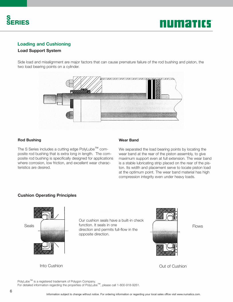
Loading and CushioningLoad Support System
Side load and misalignment are major factors that can cause premature failure of the rod bushing and piston, the two load bearing points on a cylinder.
Rod Bushing
The S Series includes a cutting edge PolyLube™ com-posite rod bushing that is extra long in length. The com-posite rod bushing is specifically designed for applications where corrosion, low friction, and excellent wear charac-teristics are desired.
Wear Band
We separated the load bearing points by locating the wear band at the rear of the piston assembly, to give maximum support even at full extension. The wear band is a stable lubricating strip placed on the rear of the pis-ton. Its width and placement serve to locate piston load at the optimum point. The wear band material has high compression integrity even under heavy loads.
Cushion Operating Principles
Our cushion seals have a built-in check function. It seals in one direction and permits full-flow in the opposite direction.
Seals Flows
Into Cushion Out of Cushion
PolyLube™ is a registered trademark of Polygon Company.For detailed information regarding the properties of PolyLube™, please call 1-800-918-9261.
Information subject to change without notice. For ordering information or regarding your local sales office visit www.numatics.com.7
SSERIES
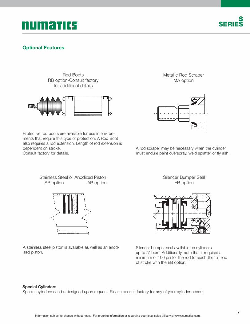
Optional Features
Special CylindersSpecial cylinders can be designed upon request. Please consult factory for any of your cylinder needs.
Rod BootsRB option-Consult factory
for additional details
Metallic Rod ScraperMA option
Stainless Steel or Anodized Piston SP option AP option
Silencer Bumper SealEB option
Protective rod boots are available for use in environ-ments that require this type of protection. A Rod Boot also requires a rod extension. Length of rod extension is dependent on stroke. Consult factory for details.
A rod scraper may be necessary when the cylinder must endure paint overspray, weld splatter or fly ash.
A stainless steel piston is available as well as an anod-ized piston.
Silencer bumper seal available on cylindersup to 5" bore. Additionally, note that it requires a minimum of 100 psi for the rod to reach the full end of stroke with the EB option.
Information subject to change without notice. For ordering information or regarding your local sales office visit www.numatics.com.8
S SERIES
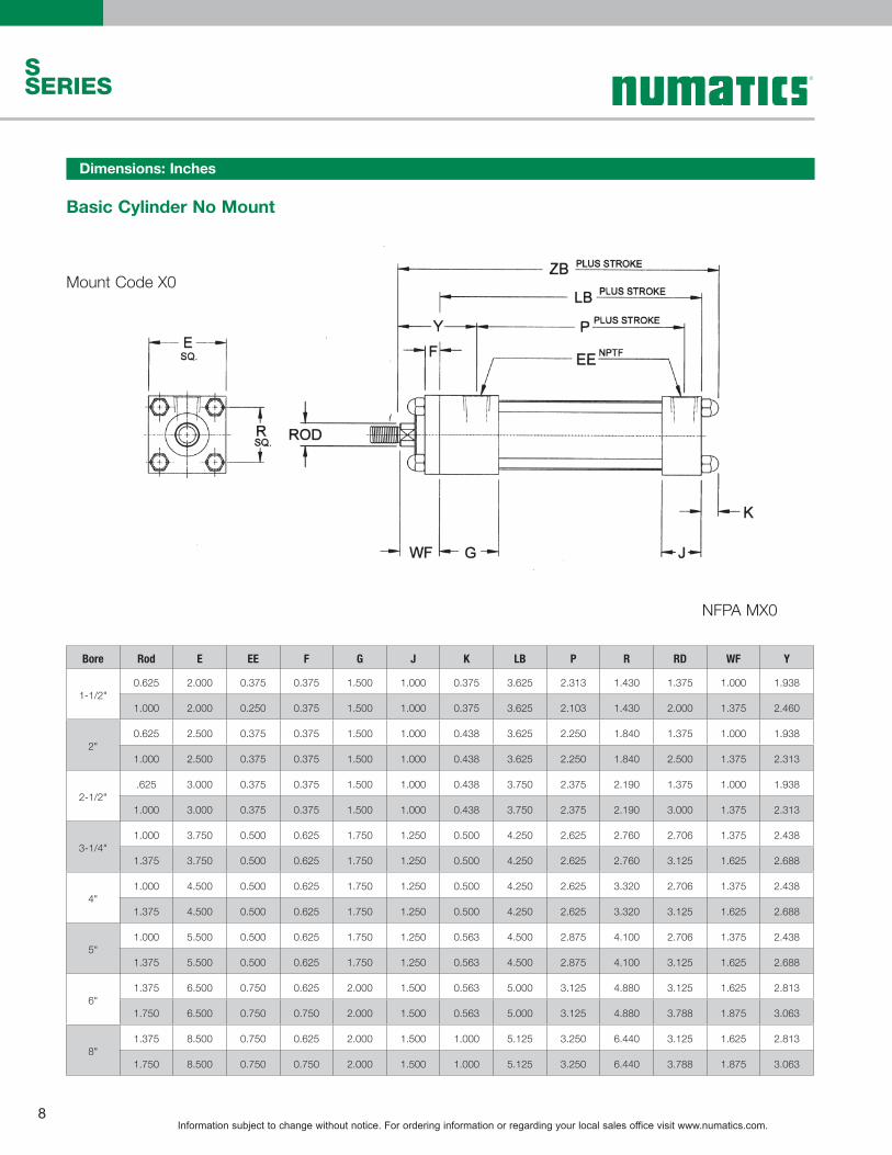
Basic Cylinder No Mount
Mount Code X0
NFPA MX0
Bore Rod E EE F G J K LB P R RD WF Y
1-1/2"0.625 2.000 0.375 0.375 1.500 1.000 0.375 3.625 2.313 1.430 1.375 1.000 1.938
1.000 2.000 0.250 0.375 1.500 1.000 0.375 3.625 2.103 1.430 2.000 1.375 2.460
2"0.625 2.500 0.375 0.375 1.500 1.000 0.438 3.625 2.250 1.840 1.375 1.000 1.938
1.000 2.500 0.375 0.375 1.500 1.000 0.438 3.625 2.250 1.840 2.500 1.375 2.313
2-1/2".625 3.000 0.375 0.375 1.500 1.000 0.438 3.750 2.375 2.190 1.375 1.000 1.938
1.000 3.000 0.375 0.375 1.500 1.000 0.438 3.750 2.375 2.190 3.000 1.375 2.313
3-1/4"1.000 3.750 0.500 0.625 1.750 1.250 0.500 4.250 2.625 2.760 2.706 1.375 2.438
1.375 3.750 0.500 0.625 1.750 1.250 0.500 4.250 2.625 2.760 3.125 1.625 2.688
4"1.000 4.500 0.500 0.625 1.750 1.250 0.500 4.250 2.625 3.320 2.706 1.375 2.438
1.375 4.500 0.500 0.625 1.750 1.250 0.500 4.250 2.625 3.320 3.125 1.625 2.688
5"1.000 5.500 0.500 0.625 1.750 1.250 0.563 4.500 2.875 4.100 2.706 1.375 2.438
1.375 5.500 0.500 0.625 1.750 1.250 0.563 4.500 2.875 4.100 3.125 1.625 2.688
6"1.375 6.500 0.750 0.625 2.000 1.500 0.563 5.000 3.125 4.880 3.125 1.625 2.813
1.750 6.500 0.750 0.750 2.000 1.500 0.563 5.000 3.125 4.880 3.788 1.875 3.063
8"1.375 8.500 0.750 0.625 2.000 1.500 1.000 5.125 3.250 6.440 3.125 1.625 2.813
1.750 8.500 0.750 0.750 2.000 1.500 1.000 5.125 3.250 6.440 3.788 1.875 3.063
Dimensions: Inches

Information subject to change without notice. For ordering information or regarding your local sales office visit www.numatics.com.9
SSERIES
Rod EndsStandard and Optional
Style #1 (Standard Male)Style #2 (Optional Male)
Style #3 (Optional Female)
Bore Rod KK(1) KK(2) KK(3) A B C D NA LAF WF
1-1/2"0.625 7/16-20 1/2-20 7/16-20 0.750 1.125 0.375 0.500 0.585 1.750 1.000
1.000 3/4-16 7/8-14 3/4-16 1.125 1.400 0.500 0.813 0.960 2.500 1.375
2"0.625 7/16-20 1/2-20 7/16-20 0.750 1.125 0.375 0.500 0.585 1.750 1.000
1.000 3/4-16 7/8-14 3/4-16 1.125 1.500 0.500 0.813 0.960 2.500 1.375
2-1/2"0.625 7/16-20 1/2-20 7/16-20 0.750 1.125 0.375 0.500 0.585 1.750 1.000
1.000 3/4-16 7/8-14 3/4-16 1.125 1.500 0.500 0.813 0.960 2.500 1.375
3-1/4"1.000 3/4-16 7/8-14 3/4-16 1.125 1.500 0.500 0.813 0.960 2.500 1.375
1.375 1-14 1 1/4-12 1-14 1.625 2.000 0.625 1.125 1.313 3.230 1.625
4"1.000 3/4-16 7/8-14 3/4-16 1.125 1.500 0.500 0.813 0.960 2.500 1.375
1.375 1-14 1 1/4-12 1-14 1.625 2.000 0.625 1.125 1.313 3.250 1.625
5"1.000 3/4-16 7/8-14 3/4-16 1.125 1.500 0.500 0.813 0.960 2.500 1.375
1.375 1-14 1 1/4-12 1-14 1.625 2.000 0.625 1.125 1.313 3.250 1.625
6"1.375 1-14 1 1/4-12 1-14 1.625 2.000 0.625 1.125 1.313 3.250 1.625
1.750 1 1/4-12 1 1/2-12 1 1/4-12 2.000 2.375 0.750 1.500 1.688 3.875 1.875
8"1.375 1-14 1 1/4-12 1-14 1.625 2.000 0.625 1.125 1.313 3.250 1.625
1.750 1 1/4-12 1 1/2-12 1 1/4-12 2.000 2.375 0.750 1.500 1.688 3.875 1.875
Dimensions: Inches

Information subject to change without notice. For ordering information or regarding your local sales office visit www.numatics.com.10
S SERIES
Flange Mounts
E
TFWF
FB (CLEARANCE HOLE) BOLT4 PLACES
E
TFZF + STROKE
FB (CLEARANCE HOLE) BOLT4 PLACES
Mount Code F1 - Head Rectangular Flange Mount Code F2 - Cap Rectangular Flange
Mount Code E3 (8" Bore Only) - Head Square Mount
Mount Code E4 (8" Bore Only) - Cap Square Mount
NFPA MF1 NFPA MF2
NFPA ME3 NFPA ME4
Dimensions: Inches
Bore Rod FB FH R TF UF W ZJ ZF
1-1/2"0.625 0.250 0.375 1.430 2.750 3.375 0.625 4.625 5.000
1.000 0.250 0.375 1.430 2.750 3.375 1.000 5.000 5.375
2"0.625 0.313 0.375 1.840 3.375 4.125 0.625 4.625 5.000
1.000 0.313 0.375 1.840 3.375 4.125 1.000 5.000 5.375
2-1/2"0.625 0.313 0.375 2.190 3.875 4.625 0.625 4.750 5.125
1.000 0.313 0.375 2.190 3.875 4.625 1.000 5.125 5.500
3-1/4"1.000 0.375 0.625 2.760 4.688 5.500 0.750 5.625 6.250
1.375 0.375 0.625 2.760 4.688 5.500 1.000 5.875 6.500
4"1.000 0.375 0.625 3.320 5.438 6.250 0.750 5.625 6.250
1.375 0.375 0.625 3.320 5.438 6.250 1.000 5.875 6.500
5"1.000 0.500 0.625 4.100 6.625 7.625 0.750 5.875 6.500
1.375 0.500 0.625 4.100 6.625 7.625 1.000 6.125 6.750
6"1.375 0.500 0.750 4.875 7.625 8.625 0.875 6.625 7.375
1.750 0.500 0.750 4.875 7.625 8.625 1.125 6.875 7.625
8"1.375 0.625 N/A N/A 7.578 N/A 1.625 N/A 6.750
1.750 0.625 N/A N/A 7.578 N/A 1.875 N/A 7.000

Information subject to change without notice. For ordering information or regarding your local sales office visit www.numatics.com.11
SSERIES
Bottom Tap and Clevis Mount
Mount Code S4 - Bottom Tapped Mount
Mount Code P1 - Fixed Clevis Mount
NFPA MS4
NFPA MP1
Dimensions: Inches
Bore Rod NT TK TN SN XT
1-1/2" 0.625 1/4-20 0.375 0.625 2.250 1.9381.000 1/4-20 0.313 0.625 2.250 2.313
2" 0.625 5/16-18 0.500 0.875 2.250 1.9381.000 5/16-18 0.500 0.875 2.250 2.313
2-1/2" 0.625 3/8-16 0.625 1.250 2.375 1.9381.000 3/8-16 0.625 1.250 2.375 2.313
3-1/4" 1.000 1/2-13 0.750 1.500 2.625 2.4381.375 1/2-13 0.750 1.500 2.625 2.688
4" 1.000 1/2-13 0.750 2.063 2.625 2.4381.375 1/2-13 0.750 2.063 2.625 2.688
5" 1.000 5/8-11 1.000 2.688 2.875 2.4381.375 5/8-11 1.000 2.688 2.875 2.688
6" 1.375 3/4-10 1.125 3.250 3.125 2.8131.750 3/4-10 1.125 3.250 3.125 3.063
8" 1.375 3/4-10 1.125 4.500 3.250 2.8131.750 3/4-10 1.125 4.500 3.250 3.063
Bore Rod CB CD CW L M XC
1-1/2" 0.625 0.750 0.500 0.500 0.750 0.500 5.3751.000 0.750 0.500 0.500 0.750 0.500 5.750
2" 0.625 0.750 0.500 0.500 0.750 0.500 5.3751.000 0.750 0.500 0.500 0.750 0.500 5.750
2-1/2" 0.625 0.750 0.500 0.500 0.750 0.500 5.5001.000 0.750 0.500 0.500 0.750 0.500 5.875
3-1/4" 1.000 1.250 0.750 0.625 1.250 0.750 6.8751.375 1.250 0.750 0.625 1.250 0.750 7.125
4" 1.000 1.250 0.750 0.625 1.250 0.750 6.8751.375 1.250 0.750 0.625 1.250 0.750 7.125
5" 1.000 1.250 0.750 0.625 1.250 0.750 7.1251.375 1.250 0.750 0.625 1.250 0.750 7.375
6" 1.375 1.500 1.000 0.750 1.500 1.000 8.1251.750 1.500 1.000 0.750 1.500 1.000 8.375
8" 1.375 1.500 1.000 0.750 1.500 1.000 8.2501.750 1.500 1.000 0.750 1.500 1.000 8.500

Information subject to change without notice. For ordering information or regarding your local sales office visit www.numatics.com.12
S SERIES
Extended Tie Rod MountsMount Code X3 - Extended Tie Rods - Head End NFPA MX3
Mount Code X2 - Extended Tie Rods - Cap End NFPA MX2
Mount Code X1 - Extended Tie Rods - Both Ends NFPA MX1
Dimensions: Inches
Bore Rod BB DD FH R W ZJ
1-1/2"0.625 1.000 1/4-28 0.375 1.430 0.625 4.625
1.000 1.000 1/4-28 0.375 1.430 1.000 5.000
2"0.625 1.125 5/16-24 0.375 1.840 0.625 4.625
1.000 1.125 5/16-24 0.375 1.840 1.000 5.000
2-1/2"0.625 1.125 5/16-24 0.375 2.190 0.625 4.750
1.000 1.125 5/16-24 0.375 2.190 1.000 5.125
3-1/4"1.000 1.375 3/8-24 0.625 2.760 0.750 5.625
1.375 1.375 3/8-24 0.625 2.760 1.000 5.875
4"1.000 1.375 3/8-24 0.625 3.320 0.750 5.625
1.375 1.375 3/8-24 0.625 3.320 1.000 5.875
5"1.000 1.813 1/2-20 0.625 4.100 0.750 5.875
1.375 1.813 1/2-20 0.625 4.100 1.000 6.125
6"1.375 1.813 1/2-20 0.750 4.880 0.875 6.625
1.750 1.813 1/2-20 0.750 4.880 1.125 6.875
8"1.375 2.313 5/8-18 N/A 6.440 1.625 6.750
1.750 2.313 5/8-18 N/A 6.440 1.875 7.000

Information subject to change without notice. For ordering information or regarding your local sales office visit www.numatics.com.13
SSERIES
Trunnion Mounts
Mount Code T1 - Head Trunnion Mount NFPA MT1
Mount Code T2 - Cap Trunnion Mount NFPA MT2
Dimensions: Inches
Bore Rod TD TL UT XG XJ
1-1/2"0.625 1.000 1.000 4.000 1.750 4.125
1.000 1.000 1.000 4.000 2.125 4.500
2"0.625 1.000 1.000 4.500 1.750 4.125
1.000 1.000 1.000 4.500 2.125 4.500
2-1/2"0.625 1.000 1.000 5.000 1.750 4.250
1.000 1.000 1.000 5.000 2.125 4.625
3-1/4"1.000 1.000 1.000 5.750 2.250 5.000
1.375 1.000 1.000 5.750 2.500 5.250
4"1.000 1.000 1.000 6.500 2.250 5.000
1.375 1.000 1.000 6.500 2.500 5.250
5"1.000 1.000 1.000 7.500 2.250 5.250
1.375 1.000 1.000 7.500 2.500 5.500
6"1.375 1.375 1.375 9.250 2.625 5.875
1.750 1.375 1.375 9.250 2.875 6.125
8"1.375 1.375 1.375 11.250 2.625 6.000
1.750 1.375 1.375 11.250 2.875 6.250

Information subject to change without notice. For ordering information or regarding your local sales office visit www.numatics.com.14
S SERIES
This configuration has a piston rod which extends out both ends of the cylinder. It is also called a through rod cylinder.
DA Option
Double Rod End Cylinders
Dimensions: Inches
Bore Rod A C D E EE F G K KK LD P R SN SS RD WF Y ZM
1-1/2"0.625 0.750 0.375 0.500 2.000 0.375 0.375 1.500 0.375 7/16-20 4.125 2.250 1.430 2.250 3.375 1.375 1.000 1.938 6.1251.000 1.125 0.500 0.813 2.000 0.250 0.375 1.500 0.375 3/4-16 4.125 1.955 1.430 2.250 3.375 2.000 1.375 2.460 6.875
2"0.625 0.750 0.375 0.500 2.500 0.375 0.375 1.500 0.438 7/16-20 4.125 2.250 1.840 2.250 3.375 1.375 1.000 1.938 6.1251.000 1.125 0.500 0.813 2.500 0.375 0.375 1.500 0.438 3/4-16 4.125 2.250 1.840 2.250 3.375 2.500 1.375 2.313 6.875
2-1/2"0.625 0.750 0.375 0.500 3.000 0.375 0.375 1.500 0.438 7/16-20 4.250 2.375 2.190 2.375 3.500 1.375 1.000 1.938 6.2501.000 1.125 0.500 0.813 3.000 0.375 0.375 1.500 0.438 3/4-16 4.250 2.375 2.190 2.375 3.500 3.000 1.375 2.313 7.000
3-1/4"1.000 1.125 0.500 0.813 3.750 0.500 0.625 1.750 0.500 3/4-16 4.750 2.625 2.760 2.625 3.750 2.706 1.375 2.438 7.5001.375 1.625 0.625 1.125 3.750 0.500 0.625 1.750 0.500 1-14 4.750 2.625 2.760 2.625 3.750 3.125 1.625 2.688 8.000
4"1.000 1.125 0.500 0.813 4.500 0.500 0.625 1.750 0.500 3/4-16 4.750 2.625 3.320 2.625 3.750 2.706 1.375 2.438 7.5001.375 1.625 0.625 1.125 4.500 0.500 0.625 1.750 0.500 1-14 4.750 2.625 3.320 2.625 3.750 3.125 1.625 2.688 8.000
5"1.000 1.125 0.500 0.813 5.500 0.500 0.625 1.750 0.563 3/4-16 5.000 2.875 4.100 2.875 3.625 2.706 1.375 2.438 7.5001.375 1.625 0.625 1.125 5.500 0.500 0.625 1.750 0.563 1-14 5.000 2.875 4.100 2.875 3.625 3.125 1.625 2.688 8.250
6"1.375 1.625 0.625 1.125 6.500 0.750 0.625 2.000 0.563 1-14 5.500 3.125 4.880 3.125 4.125 3.125 1.625 2.813 8.7501.750 2.000 0.750 1.500 6.500 0.750 0.750 2.000 0.563 1 1/4-12 5.500 3.125 4.880 3.125 4.125 3.788 1.875 3.063 9.250
8"1.375 1.625 0.625 1.125 8.500 0.750 0.625 2.000 1.000 1-14 5.625 3.250 6.440 3.250 4.250 3.125 1.625 2.813 8.8751.750 2.000 0.750 1.500 8.500 0.750 0.750 2.000 1.000 1 1/4-12 5.625 3.250 6.440 3.250 4.250 3.788 1.875 3.063 9.375

Information subject to change without notice. For ordering information or regarding your local sales office visit www.numatics.com.15
SSERIES
Accessories - Stainless SteelEye Bracket
Rod Clevis
Dimensions: Inches
Part No. A CA CB CD CE CW CX DD E ER F FL KK LR M MR R
Eye Bracket
S500-101 - - 0.750 0.500 - - - 0.406 2.500 - 0.375 1.125 - 0.750 0.500 0.563 1.630
S500-102 - - 1.250 0.750 - - - 0.531 3.500 - 0.625 1.875 - 1.250 0.750 0.875 2.560
S500-103 - - 1.500 1.000 - - - 0.656 4.500 - 0.750 2.250 - 1.500 1.000 1.250 3.250
S500-104 - - 2.000 1.375 - - - 0.656 5.000 - 0.875 3.000 - 2.125 1.375 1.625 3.810
S500-105 - - 2.500 1.750 - - - 0.906 6.500 - 0.875 3.125 - 2.250 1.750 2.125 4.950
Rod Clevis
S500-301 0.750 - 0.750 0.500 1.500 0.500 1.000 - - 0.500 - - 7/16-20 - - - -
S500-302 0.750 - 0.750 0.500 1.500 0.500 1.000 - - 0.500 - - 1/2-20 - - - -
S500-303 1.125 - 1.250 0.750 2.375 0.625 1.250 - - 0.750 - - 3/4-16 - - - -
S500-304 1.625 - 1.500 1.000 3.125 0.750 1.500 - - 1.000 - - 7/8-14 - - - -
S500-305 1.625 - 1.500 1.000 3.125 0.750 1.500 - - 1.000 - - 1-14 - - - -
S500-306 2.000 - 2.000 1.375 4.125 1.000 2.000 - - 1.375 - - 1 1/4-12 - - - -
S500-307 2.250 - 2.500 1.750 4.500 1.250 2.375 - - 1.750 - - 1 1/4-12 - - - -

Information subject to change without notice. For ordering information or regarding your local sales office visit www.numatics.com.16
S SERIES
Standard Couplers
Rod Couplers
Dimensions: Inches
Part No.A B C D E F G H Maximum
Pull LoadStandard Nickel
A500-603 B500-603 7/16-20 1 1/4 2 1/2 3/4 5/8 1/2 1 2,535
A500-604 B500-604 1/2-20 1 1/4 2 1/2 3/4 5/8 1/2 1 3,500
A500-605 B500-605 5/8-18 1 1/4 2 1/2 3/4 5/8 1/2 1 4,750
A500-606 B500-606 3/4-16 1 3/4 2 5/16 1/2 1 1/8 31/32 13/16 1 1/2 8,750
A500-607 B500-607 7/8-14 1 3/4 2 5/16 1/2 1 1/8 31/32 13/16 1 1/2 9,750
A500-608 B500-608 1-14 2 1/2 2 15/16 1/2 1 5/8 1 3/8 1 5/32 2 1/4 16,125
A500-609 B500-609 1 1/4-12 2 1/2 2 15/16 1/2 1 5/8 1 3/8 1 5/32 2 1/4 19,600
A500-610 N35-1004 1 1/2-12 3 1/4 4 3/8 13/16 2 1/4 1 3/4 1 1/2 3 34,000

Information subject to change without notice. For ordering information or regarding your local sales office visit www.numatics.com.17
SSERIES
Cylinders Bore Part Number
S series Tie Rod 1 1/2" SB6-K01
S series Tie Rod 2”-2 1/2" SB6-L01
S series Tie Rod 3 1/4"-4" SB6-P01
S series Tie Rod 5"-6" SB6-T01
S series Tie Rod 8" SB6-W01
S Series World Switch Bracket
S Series Switch Information
1
23
4
S Series World Switch Application Detail
Round Tube and Tie Rod Detail1. World Switch2. Tie Rod Bracket3. Adjustment Screw
4. Cylinder Tie Rod
.921
.559
.531
.433
.921
.559
.531
.433
Hall Effect Switch
PNP Sourcing NPN Sinking
P/N Switch Style Electrical Design Output Operating
Voltage Current Rating Switching Power
Voltage Drop
NEMA IP Rating
Temperature Rating
SH6-031 Flying Lead PNP Normally Open 6-24 VDC 0.3 Amps Max. 7.2 Watts Max. .5 Volts NEMA 6 -25º to +75º C
SH6-032 Flying Lead NPN Normally Open 6-24 VDC 0.3 Amps Max. 7.2 Watts Max. .5 Volts NEMA 6 -25º to +75º C
SH6-021 M8 Connector PNP Normally Open 6-24 VDC 0.3 Amps Max. 7.2 Watts Max. .5 Volts NEMA 6 -25º to +75º C
SH6-022 M8 Connector NPN Normally Open 6-24 VDC 0.3 Amps Max. 7.2 Watts Max. .5 Volts NEMA 6 -25º to +75º C
S Series World Switch Hall Effect Part Numbers

Information subject to change without notice. For ordering information or regarding your local sales office visit www.numatics.com.18
S SERIES
.921
.559
.531
.433
.921
.559
.531
.433
Reed Switch - Normally Open Type SR6
P/N Switch Style Electrical Design Output Operating
Voltage Current Rating Switching Power
Voltage Drop
NEMA IPRating
Temperature Rating
SR6-002 Flying Lead AC/DC REED Normally Open 5-120 VAC/DC
0.025 Amps Max.
0.001 Amps Min.3 Watts Max. 3.5 Volts NEMA 6 -25º to +75º C
SR6-004 Flying Lead AC/DC REED Normally Open 5-120 VAC/DC
0.5 Amps Max.0.005 Amps Min. 10 Watts Max. 3.0 Volts NEMA 6 -25º to +75º C
SR6-022 M8 Connector AC/DC REED Normally Open 5-50 VAC
5-60 VDC
0.025 Amps Max.
0.001 Amps Min.3 Watts Max. .5 Volts NEMA 6 -25º to +75º C
SR6-024 M8 Connector AC/DC REED Normally Open 5-50 VAC
5-60 VDC0.5 Amps Max.
0.005 Amps Min. 10 Watts Max. 3.0 Volts NEMA 6 -25º to +75º C
S Series World Switch Reed Switch Part Numbers
NFPA Interchangeable CylindersS Series (Tie Rod)
Sensor Description Standard Cord Set Quick Disconnect
Reed Switch REED-FL2-00 REED-QDS-M8UHall PNP PNP-FL2-00-U PNP-QDS-M8-UHall NPN NPN-FL2-00-U NPN-QDS-M8-U
Bore Bracket P/N
1 1/2" N99-11812" N99-1182
2 1/2" N99-11823 1/4" N99-1183
4" N99-11835" N99-11846" N99-11848" N99-118410" N99-119112" N99-119114" N99-1200
See page 19, 20, & 21 for sensor specifications
Information subject to change without notice. For ordering information or regarding your local sales office visit www.numatics.com.19
SSERIES
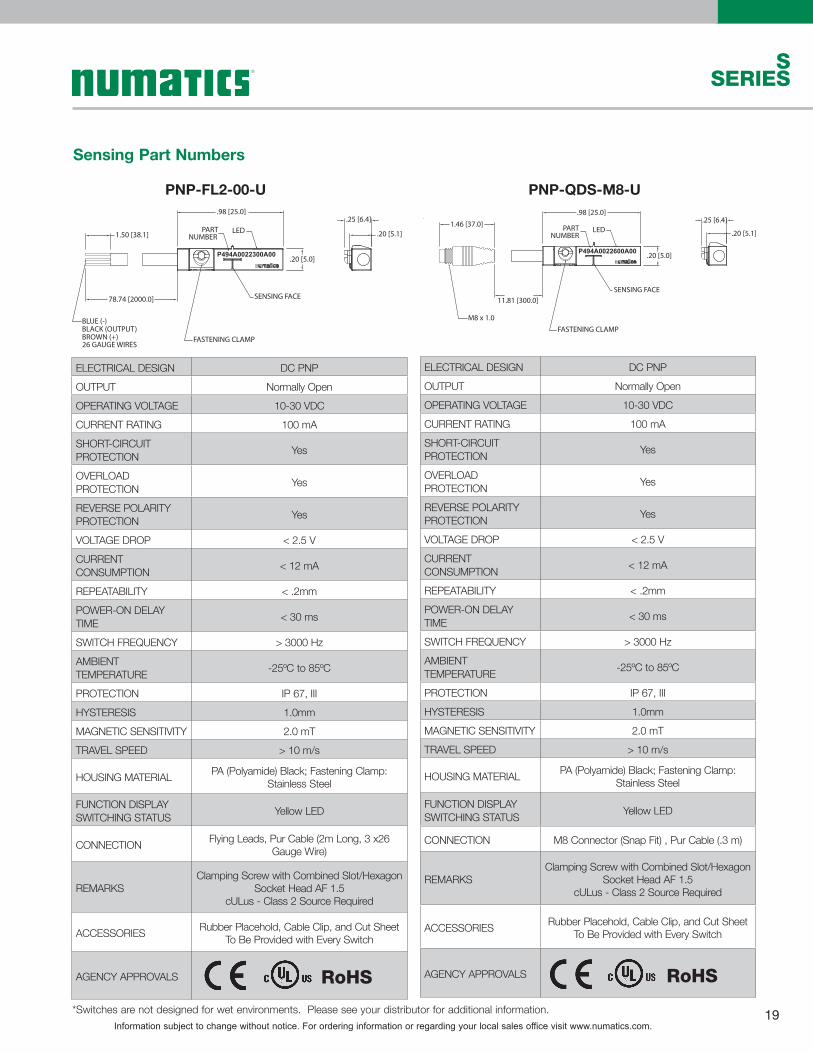
ELECTRICAL DESIGN DC PNPOUTPUT Normally OpenOPERATING VOLTAGE 10-30 VDCCURRENT RATING 100 mASHORT-CIRCUIT PROTECTION Yes
OVERLOAD PROTECTION Yes
REVERSE POLARITY PROTECTION Yes
VOLTAGE DROP < 2.5 VCURRENT CONSUMPTION < 12 mA
REPEATABILITY < .2mmPOWER-ON DELAY TIME < 30 ms
SWITCH FREQUENCY > 3000 HzAMBIENT TEMPERATURE -25ºC to 85ºC
PROTECTION IP 67, IIIHYSTERESIS 1.0mmMAGNETIC SENSITIVITY 2.0 mTTRAVEL SPEED > 10 m/s
HOUSING MATERIAL PA (Polyamide) Black; Fastening Clamp:Stainless Steel
FUNCTION DISPLAY SWITCHING STATUS Yellow LED
CONNECTION Flying Leads, Pur Cable (2m Long, 3 x26 Gauge Wire)
REMARKSClamping Screw with Combined Slot/Hexagon
Socket Head AF 1.5cULus - Class 2 Source Required
ACCESSORIES Rubber Placehold, Cable Clip, and Cut SheetTo Be Provided with Every Switch
AGENCY APPROVALS
ELECTRICAL DESIGN DC PNPOUTPUT Normally OpenOPERATING VOLTAGE 10-30 VDCCURRENT RATING 100 mASHORT-CIRCUIT PROTECTION Yes
OVERLOAD PROTECTION Yes
REVERSE POLARITY PROTECTION Yes
VOLTAGE DROP < 2.5 VCURRENT CONSUMPTION < 12 mA
REPEATABILITY < .2mmPOWER-ON DELAY TIME < 30 ms
SWITCH FREQUENCY > 3000 HzAMBIENT TEMPERATURE -25ºC to 85ºC
PROTECTION IP 67, IIIHYSTERESIS 1.0mmMAGNETIC SENSITIVITY 2.0 mTTRAVEL SPEED > 10 m/s
HOUSING MATERIAL PA (Polyamide) Black; Fastening Clamp:Stainless Steel
FUNCTION DISPLAY SWITCHING STATUS Yellow LED
CONNECTION M8 Connector (Snap Fit) , Pur Cable (.3 m)
REMARKSClamping Screw with Combined Slot/Hexagon
Socket Head AF 1.5cULus - Class 2 Source Required
ACCESSORIES Rubber Placehold, Cable Clip, and Cut SheetTo Be Provided with Every Switch
AGENCY APPROVALS
.98 [25.0]
.20 [5.0]
SENSING FACE
LED
P494A0022600A00
.25 [6.4]
.20 [5.1]
11.81 [300.0]
1.46 [37.0]
M8 x 1.0
PARTNUMBER
FASTENING CLAMP
.98 [25.0]
.20 [5.0]
FASTENING CLAMP
SENSING FACE
LED
P494A0022300A00
.25 [6.4]
.20 [5.1]PARTNUMBER
78.74 [2000.0]
1.50 [38.1]
BLUE (-)BLACK (OUTPUT) BROWN (+) 26 GAUGE WIRES
PNP-FL2-00-U PNP-QDS-M8-U
RoHS RoHS
Sensing Part Numbers
*Switches are not designed for wet environments. Please see your distributor for additional information.

Information subject to change without notice. For ordering information or regarding your local sales office visit www.numatics.com.20
S SERIES
*Switches are not designed for wet environments. Please see your distributor for additional information.
ELECTRICAL DESIGN DC NPNOUTPUT Normally OpenOPERATING VOLTAGE 10-30 VDCCURRENT RATING 100 mASHORT-CIRCUIT PROTECTION Yes
OVERLOAD PROTECTION Yes
REVERSE POLARITY PROTECTION Yes
VOLTAGE DROP < 2.5 VCURRENT CONSUMPTION < 12 mA
REPEATABILITY < .2mmPOWER-ON DELAY TIME < 30 ms
SWITCH FREQUENCY > 3000 HzAMBIENT TEMPERATURE -25ºC to 85ºC
PROTECTION IP 67, IIIHYSTERESIS 1.0mmMAGNETIC SENSITIVITY 2.0 mTTRAVEL SPEED > 10 m/s
HOUSING MATERIAL PA (Polyamide) Black; Fastening Clamp:Stainless Steel
FUNCTION DISPLAY SWITCHING STATUS Yellow LED
CONNECTION M8 Connector (Snap Fit) , Pur Cable (.3 m)
REMARKSClamping Screw with Combined Slot/Hexagon
Socket Head AF 1.5cULus - Class 2 Source Required
ACCESSORIES Rubber Placehold, Cable Clip, and Cut SheetTo Be Provided with Every Switch
AGENCY APPROVALS
.98 [25.0]
.20 [5.0]
SENSING FACE
LED
P494A0022700A00
.25 [6.4]
.20 [5.1]
11.81 [300.0]
1.46 [37.0]
M8 x 1.0
PARTNUMBER
FASTENING CLAMP
ELECTRICAL DESIGN DC NPNOUTPUT Normally OpenOPERATING VOLTAGE 10-30 VDCCURRENT RATING 100 mASHORT-CIRCUIT PROTECTION Yes
OVERLOAD PROTECTION Yes
REVERSE POLARITY PROTECTION Yes
VOLTAGE DROP < 2.5 VCURRENT CONSUMPTION < 12 mA
REPEATABILITY < .2mmPOWER-ON DELAY TIME < 30 ms
SWITCH FREQUENCY > 3000 HzAMBIENT TEMPERATURE -25ºC to 85ºC
PROTECTION IP 67, IIIHYSTERESIS 1.0mmMAGNETIC SENSITIVITY 2.0 mTTRAVEL SPEED > 10 m/s
HOUSING MATERIAL PA (Polyamide) Black; Fastening Clamp:Stainless Steel
FUNCTION DISPLAY SWITCHING STATUS Yellow LED
CONNECTION Flying Leads, Pur Cable (2m Long, 3 x26 Gauge Wire)
REMARKSClamping Screw with Combined Slot/Hexagon
Socket Head AF 1.5cULus - Class 2 Source Required
ACCESSORIES Rubber Placehold, Cable Clip, and Cut SheetTo Be Provided with Every Switch
AGENCY APPROVALS
.98 [25.0]
.20 [5.0]
SENSING FACE
LED
P494A0022400A00
.25 [6.4]
.20 [5.1]PART
NUMBER
78.74 [2000.0]
1.50 [38.1]
BLUE (-)BLACK (OUTPUT) BROWN (+) 26 GAUGE WIRES
FASTENING CLAMP
NPN-FL2-00-U NPN-QDS-M8-U
RoHS RoHS
Sensing Part Numbers

Information subject to change without notice. For ordering information or regarding your local sales office visit www.numatics.com.21
SSERIES
ELECTRICAL DESIGN AC/DC REEDOUTPUT Normally OpenOPERATING VOLTAGE 5-120 VAC/DCCURRENT RATING 100 mA*SHORT-CIRCUIT PROTECTION No
OVERLOAD PROTECTION No
REVERSE POLARITY PROTECTION Yes
VOLTAGE DROP < 5 VREPEATABILITY ± .2mmMAKETIME INCLUDING BOUNCE < .6 ms
BREAKTIME < .1 msSWITCHING POWER (MAX) 5 W
SWITCH FREQUENCY 1000 HzAMBIENT TEMPERATURE -25ºC to 70ºC
PROTECTION IP 67, IIHYSTERESIS .9mm
HOUSING MATERIAL PA (Polyamide) Black; Fastening Clamp:Stainless Steel
FUNCTION DISPLAY SWITCHING STATUS Yellow LED
CONNECTION Flying Leads, Pur Cable (2m Long, 2 x26 Gauge Wire)
REMARKS
*External Protective Circuit for Inductive Load (Valve, Contactor, Etc..) Necessary.
Conforms to 2008 NEC Section 725 III, Class 2 Circuits
Clamping Screw with Combined Slot/Hexagon Socket Head AF 1.5.
No LED Function in case of Polarity in DC Operation
ACCESSORIES Rubber Placehold, Cable Clip, and Cut SheetTo Be Provided with Every Switch
AGENCY APPROVALS
ELECTRICAL DESIGN AC/DC REEDOUTPUT Normally OpenOPERATING VOLTAGE *5-60 VDC / 5-50 VACCURRENT RATING 100 mASHORT-CIRCUIT PROTECTION No
OVERLOAD PROTECTION No
REVERSE POLARITY PROTECTION Yes
VOLTAGE DROP < 5 VREPEATABILITY ± .2mmMAKETIME INCLUDING BOUNCE < .6 ms
BREAKTIME < .1 msSWITCHING POWER (MAX) 5 W
SWITCH FREQUENCY 1000 HzAMBIENT TEMPERATURE -25ºC to 70ºC
PROTECTION IP 67, IIHYSTERESIS .9mm
HOUSING MATERIAL PA (Polyamide) Black; Fastening Clamp:Stainless Steel
FUNCTION DISPLAY SWITCHING STATUS Yellow LED
CONNECTION M8 Connector (Snap Fit), Pur Cable (.3m)
REMARKS
*External Protective Circuit for Inductive Load (Valve, Contactor, Etc..) Necessary.
Conforms to 2008 NEC Section 725 III, Class 2 Circuits
M8 Connector voltage limited to 5-60 vdc / 5-50 vac to conform with 2008 IEC 61076-2-104
Clamping Screw with Combined Slot/Hexagon Socket Head AF 1.5.
No LED Function in case of Polarity in DC Operation
ACCESSORIES Rubber Placehold, Cable Clip, and Cut SheetTo Be Provided with Every Switch
AGENCY APPROVALS
.25 [6.4]
.20 [5.1]
11.81 [300.0]
1.46 [37.0]
M8 x 1.0
1.20 [30.5]
.20 [5.0]
LED
P494A0021600A00
T AA
0809
PARTNUMBER
.22 [5.7]
FASTENING CLAMP
.25 [6.4]
.20 [5.1]
1.20 [30.5]
.20 [5.0]
LED
P494A0021300A00
T AA
0809
PARTNUMBER
.22 [5.7]
FASTENING CLAMP
78.74 [2000.0]
1.50 [38.1]
BLUE (-)BROWN (+) 26 GAUGE WIRES
REED-FL2-00 REED-QDS-M8U
RoHS RoHS
Sensing Part Numbers
*Switches are not designed for wet environments. Please see your distributor for additional information.

Information subject to change without notice. For ordering information or regarding your local sales office visit www.numatics.com.22
S SERIES
196.85 [5000]
BLUE (–)BROWN (+)BLACK (OUTPUT)26 GAUGE WIRES
1.50 [38.1]
1.2 [31]
ø.4 [10]
M8 x 1
PXCST
Quick Disconnect Cables
Order Code Type Operating Voltage Current Rating Cable Material Protection Connector
PXCST Straight 5 m Cable (3 x 26 Gauge wire) 60 AC/75 DC 3 A PUR IP 68, III M8PXC90 90° 5 m Cable (3 x 26 Gauge wire) 60 AC/75 DC 3 A PUR IP 68, III M8
BLUE (–)BROWN (+)BLACK (OUTPUT)26 GAUGE WIRES
196.85 [5000] 1.06 [27]
.71 [18]
M8 x 1ø.4 [10]
1.50 [38.1]
PXC90WiringCore colorsBK blackBN brownBU blue 13
4 1 BNBUBK
34
Information subject to change without notice. For ordering information or regarding your local sales office visit www.numatics.com.23
SSERIES
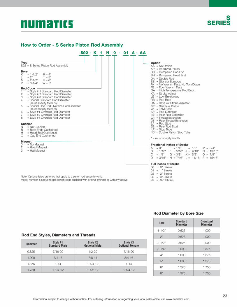
TypeS92 = S Series Piston Rod Assembly
BoreK = 1-1/2"
U = 6"L = 2"
W = 8"M = 2-1/2"P = 3-1/4"
R = 4"T = 5"
Rod Code1 = Style # 1 Standard Rod Diameter2 = Style # 2 Standard Rod Diameter3 = Style # 3 Standard Rod Diameter4 = Special Standard Rod Diameter
(must specify threads)5 = Special Rod End Oversize Rod Diameter
(must specify threads)6 = Style #1 Oversize Rod Diameter7 = Style #2 Oversize Rod Diameter8 = Style #3 Oversize Rod Diameter
CushionN = No CushionB = Both Ends CushionedH = Head End CushionedC = Cap End Cushioned
Magnet0 = No Magnet
3 = Hall Magnet2 = Reed Magnet
1 N 0 AAK
OptionAA = No Option
BH = Bumpered Head EndDA = Double RodEB = Silencer BumpersFA = No Wrench Flats, No Turn DownFB = Four Wrench FlatsGA = High Temperature Rod Boot
BC = Bumpered Cap EndAP = Anodized Piston
KA = Stroke AdjustLB = Low Breakaway
RA = Save Air Stroke AdjusterRB = Rod Boot
SP = Stainless PistonVA = FKM Seals1A* = Rod Extension1B* = Rear Rod Extension2A* = Thread Extension2B* = Rear Thread Extension3A = Rod Stud3B = Rear Rod Stud4A* = Stop Tube4D* = Double Piston Stop Tube
* = must specify length
Fractional Inches of StrokeA 0" E 1/4" I 1/2" M 3/4"B 1/16" F 5/16" J 9/16" N 13/16"C 1/8" G 3/8" K 5/8" O 7/8"D
==== 3/16" H
==== 7/16" L
==== 11/16" P
==== 15/16"
Full Inches of Stroke00 = 0" Stroke01 = 1" Stroke02 = 2" Stroke03 = 3" Stroke99 = 99" Stroke
S92 01-- -A
Rod Diameter by Bore Size
Rod End Styles, Diameters and Threads
Note: Options listed are ones that apply to a piston rod assembly only.Model number is set up to use option code supplied with original cylinder or with any above.
How to Order - S Series Piston Rod Assembly
Bore Standard Diameter
Oversized Diameter
1-1/2" 0.625 1.000
2" 0.625 1.000
2-1/2" 0.625 1.000
3-1/4" 1.000 1.375
4" 1.000 1.375
5" 1.000 1.375
6" 1.375 1.750
8" 1.375 1.750
Diameter Style #1Standard Male
Style #2Optional Male
Style #3Optional Female
0.625 7/16-20 1/2-20 7/16-20
1.000 3/4-16 7/8-14 3/4-16
1.375 1-14 1 1/4-12 1-14
1.750 1 1/4-12 1 1/2-12 1 1/4-12

Information subject to change without notice. For ordering information or regarding your local sales office visit www.numatics.com.24
S SERIES
Bore
Rod Size
1 N AAK -
Options
Cushion
S98 -
TypeS98 = S Series Repair Kit
K = 1-1/2"L = 2"
R = 4"
M = 2-1/2"
0 = Standard Rod1 = Oversize Rod
N =B =
C =H =
No CushionBoth Ends Cushioned
Cap End CushionedHead End Cushioned
PP =RA =VA =
Polypak Piston SealsSave Air Stroke AdjustFKM Seals
4D = Double Piston Stop Tube
PB =PA =
Rear Polypak Rod SealPolypak Rod Seal
LB =
MB =MA =
Low Breakaway
Rear Metallic Rod ScraperMetallic Rod Scraper
DA =
GA =EB =
Double Rod
High Temperature Rod BootSilencer Bumpers
AA = No Option
T = 5"
P = 3-1/4"U = 6"W = 8"
Bore
Rod Size
1 N AAK -
Options
Cushion
S97 -
TypeS97 = S Series Repair Kit
K = 1-1/2"L = 2"
R = 4"
M = 2-1/2"
0 = Standard Rod1 = Oversize Rod
N =B =
C =H =
No CushionBoth Ends Cushioned
Cap End CushionedHead End Cushioned
PP =RA =VA =
Polypak Piston SealsSave Air Stroke AdjustFKM Seals
4D = Double Piston Stop Tube
PB =PA =
Rear Polypak Rod SealPolypak Rod Seal
LB =
MB =MA =
Low Breakaway
Rear Metallic Rod ScraperMetallic Rod Scraper
DA =
GA =EB =
Double Rod
High Temperature Rod BootSilencer Bumpers
AA = No Option
T = 5"
P = 3-1/4"U = 6"W = 8"
How to Order - S Series Seal Kit
Note: Options listed are ones that apply to a repair kit only.Model number is set up to use option code supplied with original cylinder or with any above.
Note: Options listed are ones that apply to a repair kit only.Model number is set up to use option code supplied with original cylinder or with any above.
How to Order - S Series Repair Kit

Information subject to change without notice. For ordering information or regarding your local sales office visit www.numatics.com.25
SSERIES
Piston Rod Assembly Kit Removal/Installation Instructions 1. Loosen 4 Acorn Nuts (Part #13) to remove Full Face Retainer (Part #11) and Piston/Rod Assembly (Part #19 & #20). 2. Carefully remove old seals and wearband (Part #15, #17, & #18). Any damage to the seal may result in leakage. 3. Lubricate piston seal(s) and Wearband (Part #15) with supplied Numatics’ Lube. Examine seals before installing for any con-
tamination. Contamination may cause leakage. 4. Install Piston Seal (Part #18). Make sure the piston seal is not twisted inside groove. Next install back-up rings (Part #17) if pis-
ton seal is a T-seal. 5. Install lubricated wearband onto piston. Sink piston/rod assembly into sinker tube. See Sinker Tube Part Numbers Chart. 6. Apply lube inside the cylinder tube. 7. Sink piston/rod assembly into cylinder tube. 8. Press piston/rod assembly flush with the cylinder tube. Wipe off any lube from the face of the piston. 9. Examine seals after installing for any contamination. Contamination may cause leakage. 10. Lightly grease Rod Seal (Part #3) of Loaded Bushing before installing. This will ease the installation of the rod bushing over the
rod. 11. Assemble cylinder. Carefully place loaded bushing over the rod until getting interference. With a twisting motion, slide the bush-
ing down onto the rod and into the bushing pocket on the head. 12. Place Full Face Retainer over bushing and loosely torque Acorn Nuts to allow head and cap to rotate slightly. 13. Before final torque, place cylinder on level surface to square head and cap. Torque Acorn Nuts in a crisscross pattern. Use the
torque tolerance chart for Acorn Nuts. 14. Stroke cylinder by hand. This will enable detection of any binding. If binding does occur, repeat steps 12-14.
See Seal Installation Guide on page 27 for additional (visual) instructions.
Repair and Seal Kit Removal/Installation Instructions 1. Loosen 4 Acorn Nuts (Part #13) to remove Full Face Retainer (Part #11), Loaded Bushing (Part # 5), and Piston/Rod Assembly
(Part #19 & #20). 2. Carefully remove old seals and wearband (Part [#1, #2, #3 Seal Kit only], #8, #9, #10, #15, #17, & #18). Any damage to the
seal grooves may result in leakage. 3. Lubricate new seals and Wearband (Part #15) with supplied Numatics’ Lube. Examine seals before installing for any
contamination. Contamination may cause leakage. 4. Install Piston Seal (Part #18). Make sure the piston seal is not twisted inside groove. Next install back-up rings (Part #17) if
piston seal is a T-seal. 5. Install lubricated wearband onto piston. Sink piston/rod assembly into sinker tube. See Sinker Tube Part Numbers Chart. 6. Apply lube inside the cylinder tube. 7. Sink piston/rod assembly into cylinder tube. 8. Press piston/rod assembly flush with the cylinder tube. Wipe off any lube from the face of the piston. 9. Place Tube End Seals (Part #8) into head and cap seal grooves. Examine seals after installing for any contamination.
Contamination may cause leakage. 10. Install Rod Wiper (Part #1), Bushing O-ring (Part #2), and Rod Seal (Part #3) into bushing (Seal Kit only). Lightly grease Rod Seal
and Bushing O-ring after installation. This will ease the installation of the rod bushing over the rod and into the head. 11. Assemble cylinder. Carefully place loaded bushing over the rod until getting interference. With a twisting motion, slide the
bushing down onto the rod and into the bushing pocket on the head. 12. Place Full Face Retainer over bushing and loosely torque Acorn Nuts to allow head and cap to rotate slightly. 13. Before final torque, place cylinder on level surface to square head and cap. Torque Acorn Nuts in a crisscross pattern. Use the
torque tolerance chart for Acorn Nuts. 14. Stroke cylinder by hand. This will enable detection of any binding. If binding does occur, repeat steps 12-14.
See Seal Installation Guide on page 27 for additional (visual) instructions.
Information subject to change without notice. For ordering information or regarding your local sales office visit www.numatics.com.26
S SERIES
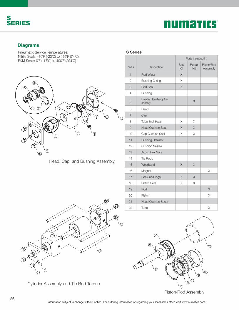
S Series
Part # Description
Parts included in:
Seal Kit
Repair Kit
Piston/Rod Assembly
1 Rod Wiper X
2 Bushing O-ring X
3 Rod Seal X
4 Bushing
5 Loaded Bushing As-sembly X
6 Head
7 Cap
8 Tube End Seals X X
9 Head Cushion Seal X X
10 Cap Cushion Seal X X
11 Bushing Retainer
12 Cushion Needle
13 Acorn Hex Nuts
14 Tie Rods
15 Wearband X X
16 Magnet X
17 Back-up Rings X X
18 Piston Seal X X
19 Rod X
20 Piston X
21 Head Cushion Spear
22 Tube X
DiagramsPneumatic Service Temperatures:Nitrile Seals: -10˚F (-23˚C) to 165˚F (74˚C)FKM Seals: 0˚F (-17˚C) to 400˚F (204˚C)
Piston/Rod Assembly
Cylinder Assembly and Tie Rod Torque
Head, Cap, and Bushing Assembly
Information subject to change without notice. For ordering information or regarding your local sales office visit www.numatics.com.27
SSERIES
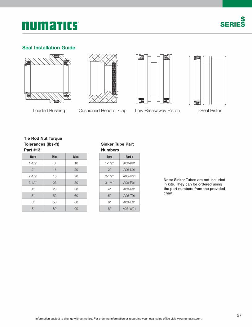
Seal Installation Guide
Loaded Bushing Cushioned Head or Cap Low Breakaway Piston T-Seal Piston
Tie Rod Nut Torque Tolerances (lbs-ft)Part #13
Bore Min. Max.
1-1/2" 8 10
2" 15 20
2-1/2" 15 20
3-1/4" 23 30
4" 23 30
5" 50 60
6" 50 60
8" 80 90
Sinker Tube Part Numbers
Bore Part #
1-1/2" A06-K91
2" A06-L91
2-1/2" A06-M91
3-1/4" A06-P91
4" A06-R91
5" A06-T91
6" A06-U91
8" A06-W91
Note: Sinker Tubes are not included in kits. They can be ordered using the part numbers from the provided chart.

World Class Supplier of Pneumatic Components
World Headquarters
Numatics, Inc. | Tel (248) 596-3200 | www.numatics.com | email: [email protected] Rev 01/15 10M-IPC-1/09© Numatics Inc. 2009 - 2013 Numatics® is registered in the United States and elsewhere
USA Numatics, Incorporated46280 Dylan DriveNovi, Michigan 48377
P: 248-596-3200 F: 248-596-3201
Canada Numatics, LtdP: 519-758-2700 F: 519-758-5540
Brazil Ascoval Ind.e Comercio LtdaP: (55) 11-4208-1700 F: (55) 11-4195-3970
México - Ascomatica SA de CVP: 52 55 58 09 56 40 (DF y Area metropolitana)P: 01 800 000 ASCO (2726) (Interior de la República) F: 52 55 58 09 56 60