n304-nca1 series:n304-nca1 seriescontent2.smcetech.com/pdf/nca1.pdf · n304-c air cylinder series...
TRANSCRIPT

N304-D
Air CylinderSeries NCA1 NFPA Interchangeable
� Medium Duty 1.5” to 4” Bore
� 12 Different NFPA Mounting Options
� Non-Rotating Option
� Tandem Cylinder Option
� Auto Switch Capable

Improved cushion capacity“Floating” cushion seal design eliminates pistonrod “bouncing” due to cracking pressure at beginning of stroke.
Compact and lightweight designThe square covers are made of an aluminum die casting and provide a lower cost, lighter weightproduct.
Air Cylinder NFPA Interchangable
Series NCA1

ø1.5”, ø2”, ø2.5”, ø3.25”, ø4”
Full range of NFPA interchangablemounting configurationsMounting Dimensions are in accordance with ANSI (NFPA) T3.6.7R2-1996, Fluid Power Systems and Products - Square HeadIndustrial Cylinders - Mounting Dimensions.
Full port design Allows for improved piston breakaway.
Increased kinetic energy absorptionThe absorption of kinetic energy had beenincrease by nearly 30% through increasecushion volume and the use of a newcushion seal.

4
How to Order …………………………………….…...…............................... 5
Specifications …………………………………………..…........................... 6
Construction / Part List / Seal Kit ………………………..…. ................... 7
Basic Mounting ……………………………………..……............................. 8
Foot Mounting ..………………………………………..…............................. 8
Front Flange Mounting ………………………….....…................................ 9
Rear Flange Mounting ……………………..………...…............................. 9
Side Tapped Mounting …………………...…………..….............................. 10
Double Detachable Rear Clevis Mounting ………...……….…................ 10
Center Trunnion Mounting ………………………….…...…........................ 11
Single Detachable Rear Clevis Mounting ………...……………….…...… 11
Double Rear Clevis Mounting ………………………….…...….................. 12
Side Lug Mounting …………………………………….…...….................... 12
Rod Trunnion Mounting …………………………………….…...…............. 13
Head Trunnion Mounting………………………….…...…........................... 13
Double Rod …………………………………….…...….......……….…...….... 14 to 16
Non-Rotating Rod and Double Rod Non-Rotating ..………….…...….... 17 to 24
Stainless Steel Rod (XC6) Low Speed (XB9) ……………………………. 25
High Temperature (XB6) / Low Temperature (XB7) ……………………... 26
Special Trunnion Location (X46US) …………………………………….… 27 & 28
Oversized Rod with Special Trunnion Location (XB5 - X46US) ………. 29
Stainless Steel Tie Rods / Tie Rod Nuts (X130US) ……………………… 30
Rod Boot …………………………………….…………….………………...... 31
Oversized Rod / Standard Rod and Non-Rotating (XB5 / X119US) ..… 32 to 36
Adjustable Stroke – Extended (XC8) ………………….………………….. 37
Adjustable Stroke – Return (XC9) ………………….……………………… 38
Dual Operation – Double Rod (XC10) ……………….……………………. 39
Dual Operation – Single Rod (XC11) ……………….…………………….. 40
Special Rod End Modifications ...........……..……………………………... 41
Accessories .…….……………..……..….…….…………………………….. 42
Auto Switch Options ..…….………..……..….……………………………... 43 to 51
Precautions ..…….……………..……..…....………………………………… 52 to 58
Table of Contents

5
Medium Duty Air Cylinder Series NCA1How To Order
NC D A1 B 150 – 04 00 – A51 – XB5
Auto SwitchStandardWith Auto Switch (Magnetic Piston)
ModelStandard CylinderNon-Rotating CylinderDouble RodMale Rod Stud
Mounting B MX0 Basic L MS1 Foot F MF1 Front Flange G MF2 Rear Flange R MS4 Side Tapped D MP2 Double Detachable Rear Clevis T MT4 Center Trunnion C MP4 Single Detachable Rear Clevis X MP1 Double Rear Clevis S MS2 Side Lug U MT1 Rod Trunnion J MT2 Head Trunnion
––––––––––––––––––––––––––––––––––––––––––––––––––––
––––––––––––––––––––––––––––––––––––––––––––––––––––
––––––––––––––––––––––––––––––––––––––––––––––––––––
––––––––––––––––––––––––––––––––––––––––––––––––––––
––––––––––––––––––––––––––––––––––––––––––––––––––––
––––––––––––––––––––––––––––––––––––––––––––––––––––
––––––––––––––––––––––––––––––––––––––––––––––––––––
––––––––––––––––––––––––––––––––––––––––––––––––––––
––––––––––––––––––––––––––––––––––––––––––––––––––––
––––––––––––––––––––––––––––––––––––––––––––––––––––
––––––––––––––––––––––––––––––––––––––––––––––––––––
––––––––––––––––––––––––––––––––––––––––––––––––––––
––––––––––––––––––––––––––––––––––––––––––––––––––––
Bore Size150200250325400
1.5"2"2.5"3.25"4"
For larger bore size up to 32" bore. Please consult CAT: N304-EX.
Standard StrokeInches
XB5 Oversized Rod XB6 High Temperature XB7 Low Temperature XB9 Low Speed XC6 Stainless Steel Piston Rod XC8 Adjustable Stroke Extended XC9 Adjustable Stroke Return XC10 Dual Operation/Double Rod XC11 Dual Operation/Single Rod XC22 Viton Seals XC35 With Coil Scraper X46US Special Trunnion Location X119US Non-Rotating Oversize Rod
X130US Stainless Steel Piston Rod,
Tie Rod, Tie Rod Nut, Cushion Valve NeedleFor special rod end modificationsplease see page 41.
–––––––––––––––––––––––––––––––––––––––––––––
–––––––––––––––––––––––––––––––––––––––––––––
–––––––––––––––––––––––––––––––––––––––––––––
–––––––––––––––––––––––––––––––––––––––––––––
–––––––––––––––––––––––––––––––––––––––––––––
–––––––––––––––––––––––––––––––––––––––––––––
–––––––––––––––––––––––––––––––––––––––––––––
–––––––––––––––––––––––––––––––––––––––––––––
–––––––––––––––––––––––––––––––––––––––––––––
–––––––––––––––––––––––––––––––––––––––––––––
–––––––––––––––––––––––––––––––––––––––––––––
–––––––––––––––––––––––––––––––––––––––––––––
–––––––––––––––––––––––––––––––––––––––––––––
–––––––––––––––––––––––––––––––––––––––––––––
–––––––––––––––––––––––––––––––––––––––––––––
No. of Switches2 Pieces1 Piece"n" Pieces
See Auto Switch Options pagesRod Boot
Without BootNylon BootNeoprene Boot
Air CushionBoth EndsNoneHead EndRod End
StrokeHundredths of an Inch
Mounting Bracket Part Numbers
MountingBracket Bore
Foot
Flange
Double Clevis(MP2)
Single Clevis
Side Lug
Double Clevis(MP1)
Part Number
150 (1.5")
NCA1-L150
NCA1-F150
NCA1-D150
NCA1-C150
NCA1-S150
NCA1-X150
∗ These Kits are for Standard Single Rod/Double Acting Cylinders without Options. For Option Kits, please contact your local SMC sales office. One Kit required per cylinder.
The SMC NCA1 expanded series NFPA Industrial Interchangeable Pneumatic Cylinders are now available in bore sizes ranging from 5” to 8” Medium Duty, and 1.5” to 14” Heavy Duty.
The NCA1 Expanded Series Cylinders offer:• Replaceable Rod Gland• A full range of NFPA interchangeable mounting configurations • Available in three construction types: Aluminum, Steel, and Stainless Steel• Composite fiber tube optional• Fully adjustable cushion For further information, please consult your local SMC sales office.
200 (2")
NCA1-L200
NCA1F200
NCA1-D200
NCA1-C200
NCA1-S200
NCA1-X200
250 (2.5")
NCA1-L250
NCA1-F250
NCA1-D250
NCA1C250
NCA1-S250
NCA1-X250
325 (3.25")
NCA1-L325
NCA1-F325
NCA1-D325
NCA1-C325
NCA1-S325
NCA1-X325
400 (4")
NCA1-L400
NCA1-F400
NCA1-D400
NCA1-C400
NCA1-S400
NCA1-X400
•
•
•
•
––––––––––––––––––––––––––
––––––––––––––––––––––––––
––––––––––––––––––––––––––
––––––––––––––––––––––––––
–––––––––––––––––––––
–––––––––––––––––––––
–––––––––––––––––––––
–––––––––––––––––––––
–––––––––––––––––––––
NilKWM
NilD
–––––––––––––––
–––––––––––––––
–––––––––––––––
–––––––––––––––
–––––––––––––––
–––––––––––––––
–––––––––––––––––––––
–––––––––––––––––––––
–––––––––––––––––––––
–––––––––––––––––––––
•NilSn
••
NilJK
NilNHR
•
•
•
•
Options

6
Series NCA1 Medium Duty Air Cylinder
Basic Weight
Additional weightper 2” stroke
∗ Rod and head trunnion maximum operating pressure for 325 and 400 bore is up to 150 psi
Specifications
Standard Strokes (in)
Weight / Aluminum Tube (lbs)
Cylinder Bores and Forces: Push Stroke
Cylinder Bores and Forces: Pull Stroke
To calculate thrust forces not shown in the table,multiply operating pressure by piston area.
How to use this tableq Locate column with desired operating pressure.w Move down that column and locate the thrust value
which is equal (or the next larger to the force to be delivered by the cylinder).
e On that same line, locate in the first (left) column the bore size recommended for your application.
Note: These are guide lines only, which must be substantiatedusing additional data specific to your application.
To calculate pull forces not shown in the table, use the fol-
lowing formula:
Pull Force = (Piston Area-Rod Area) x Working Pressure
How to use this table
q To find the force on the pull stroke, locate the required piston rod diameter in the left most column.
w Moving to the right, locate the required workingpressure.
e Deduct the value shown at the intersection from the push stroke force value determined from the Push Stroke table. The resultant is the available pull stroke table.
Base Material / Surface Treatment
Bore Size Standard Stroke Maximum Stroke1.5” 1, 2, 3, 4, 5, 6, 8, 10, 12, 14, 16, 18, 20,242”, 2.5” 1, 2, 3, 4, 5, 6, 8, 10, 12, 14, 16, 18, 20, 24 Consult SMC3.25”, 4” 1, 2, 3, 4, 5, 6, 8, 10, 12, 14, 16, 18, 20, 24, 28, 30
Bore Inch 150 (1.5”) 200 (2”) 250 (2.5”) 325 (3.25”) 400 (4”)Description Material NoteCover Aluminum alloy Silver paintTube Aluminum alloy Hard alumiteSeals Nitrile rubber PLD, PLPPiston Rod Carbon steel Hard chromatePiston Aluminum alloy Hard alumite
Bore Piston Area Forces (lbs); Push Stroke(in) (in) Operating Medium Pressure (psi)
50 60 80 100 200 2501.5 1.767 88 106 141 177 353 4422 3.142 157 188 251 314 628 785
2.5 4.909 245 295 393 491 982 12273.25 8.296 415 498 664 830 1659 2074
4 12.566 628 754 1005 1257 2513 3142
Basic type 1.58 2.35 3.19 6.03 7.79Foot mounting 1.95 2.86 3.80 7.45 10.1Flange mounting 2.30 3.22 4.34 8.85 11.66Clevis mounting 2.27 3.23 4.28 8.95 11.41Trunnion mounting 2.79 3.81 5.50 10.05 13.50For all mountings 0.38 0.48 0.51 0.97 1.06
Piston Piston Forces (lbs); Pull Stroke (Deduct the listed thrusts correspondingRod Rod to the rod size from push stroke pressure)
Diameter Area Operating Medium Pressure (psi)(in) (in) 50 60 80 100 200 250
0.625 0.307 15 18 25 31 61 771 0.785 39 47 63 79 157 196
1.375 1.485 74 89 119 148 297 371
Type
Fluid
Lubrication
Max. Operating Pressure
Min. Operating Pressure
Ambient and Fluid Temp.
Piston Speed
Mounting
Non-Rotating Accuracy
Standard
Air
Non-lube
250psi (1.75MPa)
8 psi (0.06MPa)
40 to 140F° (5 to 60°C)
2 to 20in/s
(50 to 500mm/s)
Basic, Foot
Front and Rear Flange
Side Tapped, Clevis
Center Trunnion, Side Lug
Rod and Head Trunnion
n/a
Double Rod
Air
Non-lube
250 psi (1.75MPa)
8 psi (0.06MPa)
40 to 140°F (5 to 60°C)
2 to 20in/s
(50 to 500mm/s)
Basic , Foot
Flange
Side Tapped
Center and Rod Trunnion
n/a
Non-Rotating Rod
Air
Non-lube
250 psi∗ (1.75Mpa)
15 psi (0.1MPa)
40 to 140°F (5 to 60°C)
2 to 20in/s
(50 to 500mm/s)
Basic, Foot
Front and Rear Flange
Side Tapped, Clevis
Center Trunnion, Side Lug
Rod and Head Trunnion
±0.50°

7
Medium Duty Air Cylinder Series NCA1Construction / Parts List
8 16 7 1 3 4 5 6 2
9 10
14121120 13 17 15 18 19
Stroke •(In Inches and Hundredths of Inches)
Option •Nil Single rodW Double rodK* Non-rotating
Special Options •XB5*** Over sized rodXB6*** High temperatureXB7*** Low temperatureXB5B6*** Oversized w/ high temperature*XC11 Dual Operation/Single Rod**
Bore •150200250325400
How To Order Seal Kits
How To Order Tie Rods
NC1A 150 - 11 - 2759 - 0400
Applicable Bore Tie Rod Size •Bore150 150 2759200 200 2760250 200 2760325 325 2761400 325 2761
How To Order Cylinder TubeDouble Acting Single Rod
Stroke •(In Inches and Hundredths of Inches)
* available for 150, 200 and 250 bores only** use single rod designation when ordering XC11 kit Note: XC10 seal kit order 2 single rod kits*** not available with K option
Note: Quantity is one piece. Not applicable for types: Double rod (W),Trunnion (T), XC8, XC9, XC10, XC11, Over sized rod (XB5) withfront mounts. Please consult your local SMC sales office.
NC1A W 150 - PS -
Bore •150200250325400
How To Order Piston Rod AssemblyDouble Acting Single Rod
Stroke •(In Inches and Hundredths of Inches)
NCA1 150 - 26A - 0400Bore •150200250325400
NC1A 150 - 04 - 0400
No. Description
1 Rod Cover
2 Head Cover
3 Cylinder Tube
4 Piston Rod
5 Piston
6 Cushion Sphere
7 Rod Bushing
8 Cushion Valve
9 Tie Rod
10 Tie Rod Nut
11 Retaining Ring
12 Rod Seal Retainer
13* Cushion Seal
14* Rod Seal
15* Piston Seal
16* Cushion Valve Seal
17* Cylinder Tube Gasket
18 Piston Gasket
19 Wear Ring
20 Jam Nut
Material
Aluminum alloy
Aluminum alloy
Aluminum alloy
Carbon steel
Aluminum alloy
Aluminum alloy
Bronze casting
Carbon steel
Carbon steel
Carbon steel
Carbon steel
Resin
NBR
NBR
NBR
NBR
NBR
NBR
Resin
Carbon steel
Please see below for How to Order Cylinder Tube.
Available only as an Assembled Item. Please see below for How to Order Piston Rod Assembly.
Available only as an Assembled Item. Please see below for How to Order Piston Rod Assembly.
Available only as an Assembled Item. Please see below for How to Order Piston Rod Assembly.
Available only as an Assembly Item. Please see Rod/Head Cover.
Please see below for How to Order Tie Rod.
Available only as an Assembled Item. Please see below for How to Order Seal Kit.
Available only as an Assembled Item. Please see below for How to Order Seal Kit.
Available only as an Assembled Item. Please see below for How to Order Seal Kit.
Available only as an Assembled Item. Please see below for How to Order Seal Kit.
Available only as an Assembled Item. Please see below for How to Order Seal Kit.
Available only as an Assembled Item. Please see below for How to Order Piston Rod Assembly.
Available only as an Assembled Item. Please see below for How to Order Piston Rod Assembly.
150
NCA150-02AQ6308-S
NCA150-03-Q6308-S
NCA150-13-Q6308
NCA150-31-Q6308
JM-045
200
NCA200-02AQ6309-S
NCA200-03-Q6309-S
5008-93
NCA150-31-Q6308
JM-045
250
NCA250-02AQ6310-S
NCA250-03-Q6310-S
NCA150-31-Q6308
JM-045
325
NCA325-02AQ6311-S
NCA325-03-Q6311-S
NCA325-13-Q6311
NCA325-31-Q6311
JM-10
400
NCA400-02AQ6312-S
NCA400-03-Q6312-S
NCA325-13-Q6311
NCA325-31-Q6311
JM-10
Parts List
*Components include in a seal kit.
NC1A150-10-124 NC1A325-10-125
5008-131NCA200-13-Q6309

8
Series NCA1 Medium Duty Air Cylinder
Basic Mounting Type NC A1B (MX0 Mounting Style)
Foot Mounting Type NC A1L (MS1 Mounting Style)
Bore (in)
150 (1.5")
200 (2")
250 (2.5")
325 (3.25")
400 (4")
MM
5/8
5/8
5/8
1
1
A
3/4
3/4
3/4
1 1/8
1 1/8
AA
2.02
2.6
3.1
3.9
4.7
AB
3/8
3/8
3/8
1/2
1/2
AE
2 3/16
2 11/16
3 1/8
3 13/16
4 1/2
AH
1 3/16
1 7/16
1 5/8
1 15/16
2 1/4
AL
1
1
1
1 1/4
1 1/4
AT
1/8
1/8
1/8
11/64
15/64
B
1 1/8
1 1/8
1 1/8
1 1/2
1 1/2
BA
1 1/8
1 1/8
1 1/8
1 1/2
1 1/2
C
3/8
3/8
3/8
1/2
1/2
D
9/16
9/16
9/16
7/8
7/8
DD
1/4-28
5/16-24
5/16-24
3/8-24
3/8-24
E
2
2 1/2
3
3 3/4
4 1/2
EA
0.3
0.3
0
0
0
EE
3/8
3/8
3/8
1/2
1/2
F
3/8
3/8
3/8
5/8
5/8
G
1.26
1.26
1.3
1.57
1.57
J
1.1
1.06
1.06
1.18
1.18
R
1.43
1.84
2.19
2.76
3.32
S
1 1/4
1 3/4
2 1/4
2 3/4
3 1/2
WF
1
1
1
1 3/8
1 3/8
P
2.36
2.4
2.48
2.72
2.72
Y
1.71
1.71
1.75
2.34
2.34
LF
3 5/8
3 5/8
3 3/4
4 1/4
41/4
SA
6
6
6 1/8
7 3/8
7 3/8
XA
5 5/8
5 5/8
5 3/4
6 7/8
6 7/8
ZA
6 1/16
6 3/16
6 5/16
7 5/8
7 5/8
AO
7/16
9/16
9/16
3/4
3/4
KK
7/16-20
7/16-20
7/16-20
3/4-16
3/4-16
(in)
KK
2-EE (NPTF)DD D AcrossFlats
6-AB (Hole) R
øB
AEA
øAA
S
E
øM
M
P + StrokeY
G J
LF + Stroke
SA + StrokeAO
C
AL
øB
AL
AO
WF
A
XA + Stroke
ZA + Stroke
AH
AT
AE
F
Bore (in)
150 (1.5")
200 (2")
250 (2.5")
325 (3.25")
400 (4")
MM
5/8
5/8
5/8
1
1
A
3/4
3/4
3/4
1 1/8
1 1/8
AA
2.02
2.6
3.1
3.9
4.7
B
1 1/8
1 1/8
1 1/8
1 1/2
1 1/2
BA
1 1/8
1 1/8
1 1/8
1 1/2
1 1/2
C
3/8
3/8
3/8
1/2
1/2
D
9/16
9/16
9/16
7/8
7/8
DD
1/4-28
5/16-24
5/16-24
3/8-24
3/8-24
E
2
2 1/2
3
3 3/4
4 1/2
EA
0.3
0.3
0
0
0
EE
3/8
3/8
3/8
1/2
1/2
G
1.26
1.26
1.3
1.57
1.57
J
1.1
1.06
1.06
1.18
1.18
R
1.43
1.84
2.19
2.76
3.32
P
2.36
2.4
2.48
2.72
2.72
Y
1.71
1.71
1.75
2.34
2.34
LF
3 5/8
3 5/8
3 3/4
4 1/4
4 1/4
WF
1
1
1
1 3/8
1 3/8
ZB
4 3/4
4 3/4
4 7/8
5 53/64
5 53/64
KK
7/16-20
7/16-20
7/16-20
3/4-16
3/4-16
(in)
ZB + Stroke
DD
øM
M
P + Stroke Y
G J
LF + Stroke
2-EE (NPTF)
A C
WF
EA
øB
A
øB
KK
D AcrossFlats
R
E
øAA

9
Medium Duty Air Cylinder Series NCA1Front Flange Mounting Type NC A1F (MF1 Mounting Style)
Rear Flange Mounting Type NC A1G (MF2 Mounting Style)
Bore (in)
150 (1.5")
200 (2")
250 (2.5")
325 (3.25")
400 (4")
MM
5/8
5/8
5/8
1
1
A
3/4
3/4
3/4
1 1/8
1 1/8
AA
2.02
2.6
3.1
3.9
4.7
B
1 1/8
1 1/8
1 1/8
1 1/2
1 1/2
BA
1 1/8
1 1/8
1 1/8
1 1/2
1 1/2
C
3/8
3/8
3/8
1/2
1/2
D
9/16
9/16
9/16
7/8
7/8
DD
1/4-28
5/16-24
5/16-24
3/8-24
3/8-24
E
2
2 1/2
3
3 3/4
4 1/2
EA
0.3
0.3
0
0
0
EE
3/8
3/8
3/8
1/2
1/2
F
3/8
3/8
3/8
5/8
5/8
FB
5/16
3/8
3/8
7/16
7/16
G
1.26
1.26
1.3
1.57
1.57
J
1.1
1.06
1.06
1.18
1.18
R
1.43
1.84
2.19
2.76
3.32
TF
2 3/4
3 3/8
3 7/8
4 11/16
5 7/16
P
2.36
2.4
2.48
2.72
2.72
Y
1.71
1.71
1.75
2.34
2.34
UF
3 3/8
4 1/8
4 5/8
5 1/2
6 1/4
LF
3 5/8
3 5/8
3 3/4
4 1/4
4 1/4
W
5/8
5/8
5/8
3/4
3/4
WF
1
1
1
1 3/8
1 3/8
ZB
4 3/4
4 3/4
4 7/8
5 53/64
5 53/64
KK
7/16-20
7/16-20
7/16-20
3/4-16
3/4-16
(in)
DD
2-EE (NPTF)D AcrossFlats
KK
4-FB (Hole)
ER
TF
R
UF
øM
M
P + StrokeY
G J
LF + Stroke
ZB + StrokeA
C
WF
EA
øB
A
øB
FW
øAA
Bore (in)
150 (1.5")
200 (2")
250 (2.5")
325 (3.25")
400 (4")
MM
5/8
5/8
5/8
1
1
A
3/4
3/4
3/4
1 1/8
1 1/8
AA
2.02
2.6
3.1
3.9
4.7
B
1 1/8
1 1/8
1 1/8
1 1/2
1 1/2
BA
1 1/8
1 1/8
1 1/8
1 1/2
1 1/2
C
3/8
3/8
3/8
1/2
1/2
D
9/16
9/16
9/16
7/8
7/8
DD
1/4-28
5/16-24
5/16-24
3/8-24
3/8-24
E
2
2 1/2
3
3 3/4
4 1/2
EA
0.3
0.3
0
0
0
EE
3/8
3/8
3/8
1/2
1/2
G
1.26
1.26
1.3
1.57
1.57
F
3/8
3/8
3/8
5/8
5/8
FB
5/16
3/8
3/8
7/16
7/16
J
1.1
1.06
1.06
1.18
1.18
R
1.43
1.84
2.19
2.76
3.32
XF
4 5/8
4 5/8
4 3/4
5 5/8
5 5/8
Y
1.71
1.71
1.75
2.34
2.34
UF
3 3/8
4 1/8
4 5/8
5 1/2
6 1/4
P
2.36
2.4
2.48
2.72
2.72
ZF
5
5
5 1/8
6 1/4
6 1/4
WF
1
1
1
1 3/8
1 3/8
KK
7/16-20
7/16-20
7/16-20
3/4-16
3/4-16
(in)
TF
2 3/4
3 3/8
3 7/8
4 11/16
5 7/16
DD
4-FB (Hole)
D-AcrossFlats
KK
2-EE (NPTF)
LF + Stroke
R
øBAøAA
øB
øM
M
TF
UF
P + StrokeY
G J
XF + Stroke
ZF + Stroke
A
C
WF
EA
F
RE

Side Tapped Mounting Type NC A1R (MS4 Mounting Style)
10
Series NCA1 Medium Duty Air Cylinder
Bore (in)
150 (1.5")
200 (2")
250 (2.5")
325 (3.25")
400 (4")
MM
5/8
5/8
5/8
1
1
A
3/4
3/4
3/4
1 1/8
1 1/8
AA
2.02
2.6
3.1
3.9
4.7
B
1 1/8
1 1/8
1 1/8
1 1/2
1 1/2
J
1.1
1.06
1.06
1.18
1.18
BA
1 1/8
1 1/8
1 1/8
1 1/2
1 1/2
C
3/8
3/8
3/8
1/2
1/2
D
9/16
9/16
9/16
7/8
7/8
DD
1/4-28
5/16-24
5/16-24
3/8-24
3/8-24
E
2
2 1/2
3
3 3/4
4 1/2
EA
0.3
0.3
0
0
0
EE
3/8
3/8
3/8
1/2
1/2
E/2
1
1 1/4
1 1/2
1 7/8
2 1/4
G
1.26
1.26
1.3
1.57
1.57
ND
9/32
7/16
19/32
5/8
5/8
NT
1/4-20
5/16-18
3/8-16
1/2-13
1/2-13
TN
5/8
7/8
1 1/4
1 1/2
2 1/16
P
2.36
2.4
2.48
2.72
2.72
Y
1.71
1.71
1.75
2.34
2.34
XT
1 15/16
1 15/16
1 15/16
2 7/16
2 7/16
LF
3 5/8
3 5/8
3 3/4
4 1/4
4 1/4
SN
2 1/4
2 1/4
2 3/8
2 5/8
2 5/8
WF
1
1
1
1 3/8
1 3/8
ZB
4 3/4
4 3/4
4 7/8
5 53/64
5 53/64
KK
7/16-20
7/16-20
7/16-20
3/4-16
3/4-16
R
1.43
1.84
2.19
2.76
3.32
(in)
2-EE (NPTF)DD
KK
D AcrossFlats
R
øAA
øB
øM
MTN
E
P + StrokeY
G J
SN + Stroke
ZB + StrokeA
C
WF
EA
øB
A
E/2
LF + Stroke
XT
4-NTND Deep
Double Detachable Rear Clevis Mounting Type NC A1D (MP2 Mounting Style)
Bore (in)
150 (1.5")
200 (2")
250 (2.5")
325 (3.25")
400 (4")
MM
5/8
5/8
5/8
1
1
A
3/4
3/4
3/4
1 1/8
1 1/8
AA
2.02
2.6
3.1
3.9
4.7
B
1 1/8
1 1/8
1 1/8
1 1/2
1 1/2
C
3/8
3/8
3/8
1/2
1/2
CB
3/4
3/4
3/4
1 1/4
1 1/4
D
9/16
9/16
9/16
7/8
7/8
DD
1/4-28
5/16-24
5/16-24
3/8-24
3/8-24
E
2
2 1/2
3
3 3/4
4 1/2
EA
0.3
0.3
0
0
0
EE
3/8
3/8
3/8
1/2
1/2
F
3/8
3/8
3/8
5/8
5/8
CD
1/2
1/2
1/2
3/4
3/4
CW
1/2
1/2
1/2
5/8
5/8
G
1.26
1.26
1.3
1.57
1.57
J
1.1
1.06
1.06
1.18
1.18
L
3/4
3/4
3/4
1 1/4
1 1/4
LR
5/8
5/8
5/8
1
1
P
2.36
2.4
2.48
2.72
2.72
Y
1.71
1.71
1.75
2.34
2.34
M
1/2
1/2
1/2
3/4
3/4
LF
3 5/8
3 5/8
3 3/4
4 1/4
4 1/4
ZD
6 1/4
6 1/4
6 3/8
8 1/4
8 1/4
WF
1
1
1
1 3/8
1 3/8
XD
5 3/4
5 3/4
5 7/8
7 1/2
7 1/2
KK
7/16-20
7/16-20
7/16-20
3/4-16
3/4-16
R
1.43
1.84
2.19
2.76
3.32
(in)
DD
øCD
2-EE (NPTF)
KK
D AcrossFlats
R
øAA
C
øB
øM
M
P + StrokeY
G J
LF + Stroke
XD + Stroke
A
WF
EA
M
CB
L
E
LR
F
CWCW
ZD + Stroke

Center Trunnion Mounting Type NC A1T (MT4 Mounting Style)
11
Medium Duty Air Cylinder Series NCA1
Single Detachable Rear Clevis Mounting Type NC A1C (MP4 Mounting Style)
Bore (in)
150 (1.5")
200 (2")
250 (2.5")
325 (3.25")
400 (4")
MM
5/8
5/8
5/8
1
1
A
3/4
3/4
3/4
1 1/8
1 1/8
AA
2.02
2.6
3.1
3.9
4.7
B
1 1/8
1 1/8
1 1/8
1 1/2
1 1/2
BA
1 1/8
1 1/8
1 1/8
1 1/2
1 1/2
C
3/8
3/8
3/8
1/2
1/2
D
9/16
9/16
9/16
7/8
7/8
DD
1/4-28
5/16-24
5/16-24
3/8-24
3/8-24
E
2
2 1/2
3
3 3/4
4 1/2
EA
0.3
0.3
0
0
0
EE
3/8
3/8
3/8
1/2
1/2
G
1.26
1.26
1.3
1.57
1.57
J
1.1
1.06
1.06
1.18
1.18
R
1.43
1.84
2.19
2.76
3.32
TM
2.5
3
3.5
4.5
5.25
TT
1.18
1.18
1.18
1.34
1.57
UM
4.5
5
5.5
6.5
7.25
UV
2
2.56
3.39
4.33
5.12
P
2.36
2.4
2.48
2.72
2.72
Y
1.71
1.71
1.75
2.34
2.34
LF
3 5/8
3 5/8
3 3/4
4 1/4
4 1/4
XI
2.89
2.91
2.99
3.7
3.74
WF
1
1
1
1 3/8
1 3/8
ZB
4 3/4
4 3/4
4 7/8
5 53/64
5 53/64
KK
7/16-20
7/16-20
7/16-20
3/4-16
3/4-16
(in)
TM
UV
2-EE (NPTF)
-0.0
01+
0ø
1.00
KK
D-AcrossFlats
øB
øM
M
øAA
4-DD
R0.03
R
P + StrokeY
G J
LF + StrokeZD + StrokeA
C
WF
EAø
BA
1.001.00
E
UM
XI + 1/2 Stroke
TT
Bore (in)
150 (1.5")
200 (2")
250 (2.5")
325 (3.25")
400 (4")
MM
5/8
5/8
5/8
1
1
A
3/4
3/4
3/4
1 1/8
1 1/8
AA
2.02
2.6
3.1
3.9
4.7
B
1 1/8
1 1/8
1 1/8
1 1/2
1 1/2
C
3/8
3/8
3/8
1/2
1/2
CB
3/4
3/4
3/4
1 1/4
1 1/4
D
9/16
9/16
9/16
7/8
7/8
DD
1/4-28
5/16-24
5/16-24
3/8-24
3/8-24
E
2
2 1/2
3
3 3/4
4 1/2
EA
0.3
0.3
0
0
0
EE
3/8
3/8
3/8
1/2
1/2
F
3/8
3/8
3/8
5/8
5/8
CD
1/2
1/2
1/2
3/4
3/4
G
1.26
1.26
1.3
1.57
1.57
J
1.1
1.06
1.06
1.18
1.18
L
3/4
3/4
3/4
1 1/4
1 1/4
P
2.36
2.4
2.48
2.72
2.72
Y
1.71
1.71
1.75
2.34
2.34
M
0.63
0.63
0.63
0.87
0.87
R
1.43
1.84
2.19
2.76
3.32
LF
3 5/8
3 5/8
3 3/4
4 1/4
4 1/4
ZD
6 3/8
6 3/8
6 1/2
8 3/8
8 3/8
WF
1
1
1
1 3/8
1 3/8
XD
5 3/4
5 3/4
5 7/8
7 1/2
7 1/2
KK
7/16-20
7/16-20
7/16-20
3/4-16
3/4-16
DD
R
2-EE (NPTF)
KK
D-AcrossFlats
øB
øM
M
P + StrokeY
G J
LF + Stroke
XD + Stroke
A
C
WF
EA
M
CB
L
E
F
ZD + Stroke
øAA
øCD

Double Rear Clevis Mounting Type NC A1X (MP1 Mounting Style)
12
Series NCA1 Medium Duty Air Cylinder
Side Lug Mounting Type NC A1S (MS2 Mounting Style)
Bore (in)
150 (1.5")
200 (2")
250 (2.5")
325 (3.25")
400 (4")
MM
5/8
5/8
5/8
1
1
A
3/4
3/4
3/4
1 1/8
1 1/8
AA
2.02
2.6
3.1
3.9
4.7
B
1 1/8
1 1/8
1 1/8
1 1/2
1 1/2
CB
3/4
3/4
3/4
1 1/4
1 1/4
C
3/8
3/8
3/8
1/2
1/2
CW
1/2
1/2
1/2
5/8
5/8
CD
1/2
1/2
1/2
3/4
3/4
DD
1/4-28
5/16-24
5/16-24
3/8-24
3/8-24
D
9/16
9/16
9/16
7/8
7/8
E
2
2 1/2
3
3 3/4
4 1/2
EA
0.3
0.3
0
0
0
EE
3/8
3/8
3/8
1/2
1/2
F
3/8
3/8
3/8
5/8
5/8
G
1.26
1.26
1.3
1.57
1.57
J
1.1
1.06
1.06
1.18
1.18
L
0.62
0.62
0.62
1.05
1.05
P
2.36
2.4
2.48
2.72
2.72
Y
1.71
1.71
1.75
2.34
2.34
LR
0.75
0.75
0.75
1.25
1.25
LF
3 5/8
3 5/8
3 3/4
4 1/4
4 1/4
M
0.62
0.62
0.62
0.87
0.87
WF
1
1
1
1 3/8
1 3/8
XD
5 3/8
5 3/8
5 1/2
6 7/8
6 7/8
ZB
4.75
4.75
4.88
5.83
5.83
KK
7/16-20
7/16-20
7/16-20
3/4-16
3/4-16
R
1.43
1.84
2.19
2.76
3.32
Note: Mounting dimensions are the same as NFPA (MP1) except where marked. (∗)
(in)
∗DD S.H.C.S.
∗LR
2-EE (NPTF)
KK
D AcrossFlats
øB
øM
M
XD + Stroke
P + StrokeY
G J
LF + Stroke
ZB + Stroke
A
C
WF
EA
CB
R
E∗L
∗M
∗CD
∗F CWCW
øAA
DD
Bore (in)
150 (1.5")
200 (2")
250 (2.5")
325 (3.25")
400 (4")
MM
5/8
5/8
5/8
1
1
A
3/4
3/4
3/4
1 1/8
1 1/8
C
3/8
3/8
3/8
1/2
1/2
US
3.50
4
4.50
5.75
6.50
R
1.43
1.84
2.19
2.76
3.32
B
1 1/8
1 1/8
1 1/8
1 1/2
1 1/2
ST
5/8
5/8
3/4
1
1
SU
0.94
0.94
0.94
1.25
1.25
TS
2.75
3.25
3.75
4.75
5.50
D
9/16
9/16
9/16
7/8
7/8
DD
1/4-28
5/16-24
5/16-24
3/8-24
3/8-24
E
2
2 1/2
3
3 3/4
4 1/2
EA
0.3
0.3
0
0
0
EE
3/8
3/8
3/8
1/2
1/2
SB
3/8
3/8
3/8
1/2
1/2
G
1.26
1.26
1.3
1.57
1.57
J
1.1
1.06
1.06
1.18
1.18
SW
3/8
3/8
3/8
1/2
1/2
WF
1
1
1
1 3/8
1 3/8
P
2.36
2.4
2.48
2.72
2.72
SY
0.94
0.94
0.94
1.25
1.25
LF
3.63
3.63
3.75
4.25
4.25
XS
1.38
1.38
1.38
1.88
1.88
Y
1.71
1.71
1.75
2.34
2.34
ZB
5.19
5.19
5.31
6.38
6.38
SS
2.88
2.88
3
3.25
3.25
KK
7/16-20
7/16-20
7/16-20
3/4-16
3/4-16
(in)
D AcrossFlats
KK
E
øM
M
P + StrokeY
G J
SS + Stroke
2-EE (NPTF)A C
WF
EA
øB
LF + Stroke
ZB + Stroke
E/2
ST
US
TS
øSB Screw(4) Hole
SW
SUXS
SY
SW
SU
RDD

Head Trunnion Mounting Type NC A1J (MT2 Mounting Style)
13
Medium Duty Air Cylinder Series NCA1
Bore (in)
150 (1.5")
200 (2")
250 (2.5")
325 (3.25")
400 (4")
MM
5/8
5/8
5/8
1
1
A
3/4
3/4
3/4
1 1/8
1 1/8
AA
2.02
2.6
3.1
3.9
4.7
B
1 1/8
1 1/8
1 1/8
1 1/2
1 1/2
C
3/8
3/8
3/8
1/2
1/2
D
9/16
9/16
9/16
7/8
7/8
DD
1/4-28
5/16-24
5/16-24
3/8-24
3/8-24
E
2
2 1/2
3
3 3/4
4 1/2
EA
0.3
0.3
0
0
0
EE
3/8
3/8
3/8
1/2
1/2
J
1.23
1.19
1.19
1.38
1.38
G
1.26
1.26
1.3
1.57
1.57
R
1.43
1.84
2.19
2.76
3.32
P
2.36
2.4
2.48
2.72
2.72
Y
1.71
1.71
1.75
2.34
2.34
LF
3.75
3.75
3.88
4.45
4.45
WF
1
1
1
1 3/8
1 3/8
ZB
4.75
4.75
4.88
5.83
5.83
KK
7/16-20
7/16-20
7/16-20
3/4-16
3/4-16
(in)
øAA 4-DD
R
2-EE (NPTF)
KK
D AcrossFlats
øB
øM
M
1.001.00 E
-0.0
01+
0ø
1.00
P + StrokeY
G J
LF + Stroke
ZB + StrokeA
C
WF
EA
Air Cushion Adjustable
Rod Trunnion Mounting Type NC A1U (MT1 Mounting Style)
Bore (in)
150 (1.5")
200 (2")
250 (2.5")
325 (3.25")
400 (4")
MM
5/8
5/8
5/8
1
1
A
3/4
3/4
3/4
1 1/8
1 1/8
AA
2.02
2.6
3.1
3.9
4.7
B
1 1/8
1 1/8
1 1/8
1 1/2
1 1/2
BA
1 1/8
1 1/8
1 1/8
1 1/2
1 1/2
C
3/8
3/8
3/8
1/2
1/2
D
9/16
9/16
9/16
7/8
7/8
DD
1/4-28
5/16-24
5/16-24
3/8-24
3/8-24
E
2
2 1/2
3
3 3/4
4 1/2
EA
0.3
0.3
0
0
0
EE
3/8
3/8
3/8
1/2
1/2
J
1.1
1.06
1.06
1.18
1.18
G
1.26
1.26
1.3
1.57
1.57
R
1.43
1.84
2.19
2.76
3.32
P
2.36
2.4
2.48
2.72
2.72
Y
1.71
1.71
1.75
2.34
2.34
LF
3 5/8
3 5/8
3 3/4
4 1/4
4 1/4
WF
1
1
1
1 3/8
1 3/8
ZB
4.75
4.75
4.88
5.83
5.83
KK
7/16-20
7/16-20
7/16-20
3/4-16
3/4-16
(in)
KK
D AcrossFlats
Air Cushion Adjustable
2-EE(NPTF)4-DD
R
øM
M
øB
øAAP + StrokeY
G J
LF + Stroke
ZB + Stroke
A
C
WF
EA
øB
A
1.001.00 E
-0.0
01 0
ø1.
00

Specifications
14
Series NCA1 Medium Duty Air Cylinder
(in)Bore size Standard Stroke1.5” 1, 2, 3, 4, 5, 6, 8, 10, 12, 14, 16, 18, 20, 24 2”, 2.5” 1, 2, 3, 4, 5, 6, 8, 10, 12, 14, 16, 18, 20, 243.25”, 4” 1, 2, 3, 4, 5, 6, 8, 10, 12, 14, 16, 18, 20, 24, 28, 30
Double Rod – Basic Mounting Type NC A1WB
Bore size (inch) 1.5 2 2.5 3.25 4 Media Max. Operating PressureMin. Operating PressureAmbient and Media TemperaturePiston SpeedCushion
Mounting Types
Air250 psi (17.5 kgf/cm²)
8 psi (0.5 kgf/cm²)40 to 140°F (5 to 60°C)
2 to 20 inch/sec (50 to 500mm/sec)Air Cushion Standard
Basic, Foot, Flange, Center Trunnion, Rod Trunnion
Standard Stroke List
MOUNTING BORE STROKE SUFFIXNCDA1 WEx: NCDA1WB 150-400
Auto-switch capable Double Rod
How To Order
Bore (in)
150 (1.5")
200 (2")
250 (2.5")
325 (3.25")
400 (4")
MM
5/8
5/8
5/8
1
1
A
3/4
3/4
3/4
1 1/8
1 1/8
AA
2.02
2.6
3.1
3.9
4.7
B
1 1/8
1 1/8
1 1/8
1 1/2
1 1/2
C
3/8
3/8
3/8
1/2
1/2
D
9/16
9/16
9/16
7/8
7/8
DD
1/4-28
5/16-24
5/16-24
3/8-24
3/8-24
E
2
2 1/2
3
3 3/4
4 1/2
EA
0.3
0.3
0
0
0
EE
3/8
3/8
3/8
1/2
1/2
G
1.26
1.26
1.3
1.57
1.57
K
0.28
0.34
0.34
0.42
0.42
LD
3.78
3.82
3.98
4.64
4.64
WF
1
1
1
1 3/8
1 3/8
P
2.36
2.4
2.48
2.72
2.72
R
1.43
1.84
2.19
2.76
3.32
Y
1.71
1.71
1.75
2.34
2.34
XT
1 15/16
1 15/16
1 15/16
2 7/16
2 7/16
SD
1.9
1.94
2.1
2.52
2.52
KK
7/16-20
7/16-20
7/16-20
3/4-16
3/4-16
(in)
ZM
5.78
5.82
5.98
7.4
7.4
KK
D AcrossFlats
D AcrossFlats
KK
2-EE (NPTF)DD
øAA
øB
øM
M
øM
M
øB
G K A
WF + StrokeLD + Stroke
ZM + 2 x Stroke
XT + StrokeSD + StrokeXT
Y
WF
CA
Y + StrokeP + Stroke
EA
R G
E
• Standard with air cushion• Auto-switch mounting available

Double Rod – Foot Mounting Type NC A1WL
15
Medium Duty Air Cylinder Series NCA1
Double Rod – Front Flange Mounting Type NC A1WF
Bore (in)
150 (1.5")
200 (2")
250 (2.5")
325 (3.25")
400 (4")
MM
5/8
5/8
5/8
1
1
A
3/4
3/4
3/4
1 1/8
1 1/8
AA
2.02
2.6
3.1
3.9
4.7
AB
3/8
3/8
3/8
1/2
1/2
AE
2 3/16
2 11/16
3 1/8
3 13/16
4 1/2
AH
1 3/16
1 7/16
1 5/8
1 15/16
2 1/4
AL
1
1
1
1 1/4
1 1/4
AT
1/8
1/8
1/8
11/64
15/64
B
1 1/8
1 1/8
1 1/8
1 1/2
1 1/2
C
3/8
3/8
3/8
1/2
1/2
D
9/16
9/16
9/16
7/8
7/8
DD
1/4-28
5/16-24
5/16-24
3/8-24
3/8-24
E
2
2 1/2
3
3 3/4
4 1/2
EA
0.3
0.3
0
0
0
EE
3/8
3/8
3/8
1/2
1/2
G
1.26
1.26
1.3
1.57
1.57
K
0.41
0.47
0.47
0.59
0.65
S
1 1/4
1 3/4
2 1/4
2 3/4
3 1/2
WF
1
1
1
1 3/8
1 3/8
P
2.36
2.4
2.48
2.72
2.72
Y
1.71
1.71
1.75
2.34
2.34
LD
3.78
3.82
3.98
4.64
4.64
SL
5.78
5.82
5.98
7.14
7.14
ZM
5.78
5.82
5.98
7.40
7.40
AO
7/16
9/16
9/16
3/4
3/4
KK
7/16-20
7/16-20
7/16-20
3/4-16
3/4-16
(in)
D-AcrossFlats
DD
KKKK
D-AcrossFlats
R
K
øAA
øM
M
øBøB
øM
M
WF + Stroke
A
G
SL + Stroke
AO AL AL AO
G
LD + Stroke
ZM + 2 x Stroke
Y + StrokeP + Stroke
C
EA
Y
WFA
S
AT
AH
AE
E
2-EE (NPTF)
6-øAB (Hole)
R
1.43
1.84
2.19
2.76
3.32
Bore (in)
150 (1.5")
200 (2")
250 (2.5")
325 (3.25")
400 (4")
MM
5/8
5/8
5/8
1
1
A
3/4
3/4
3/4
1 1/8
1 1/8
AA
2.02
2.6
3.1
3.9
4.7
B
1 1/8
1 1/8
1 1/8
1 1/2
1 1/2
C
3/8
3/8
3/8
1/2
1/2
D
9/16
9/16
9/16
7/8
7/8
DD
1/4-28
5/16-24
5/16-24
3/8-24
3/8-24
E
2
2 1/2
3
3 3/4
4 1/2
EA
0.3
0.3
0
0
0
EE
3/8
3/8
3/8
1/2
1/2
F
3/8
3/8
3/8
5/8
5/8
FB
5/16
3/8
3/8
7/16
7/16
G
1.26
1.26
1.3
1.57
1.57
K
0.28
0.34
0.34
0.42
0.42
R
1.43
1.84
2.19
2.76
3.32
TF
2 3/4
3 3/8
3 7/8
4 11/16
5 7/16
P
2.36
2.4
2.48
2.72
2.72
Y
1.71
1.71
1.75
2.34
2.34
UF
3 3/8
4 1/8
4 5/8
5 1/2
6 1/4
LD
3.78
3.82
3.98
4.64
4.64
ZM
5.78
5.82
5.98
7.40
7.40
WF
1
1
1
1 3/8
1 3/8
W
5/8
5/8
5/8
3/4
3/4
KK
7/16-20
7/16-20
7/16-20
3/4-16
3/4-16
(in)
KK
D-AcrossFlats
KK
D-AcrossFlats
EA
R
øB
øM
M
øM
M
øB
øAA
A
Y + Stroke
DD
UF
E
G K
ZM + 2 x (Stroke)LD + Stroke
G
WF
F
A W
2-EE (NPTF)Y
C
P + Stroke
R
4-øFB (Hole)
TF
WF + Stroke

16
Series NCA1 Medium Duty Air Cylinder
Double Rod – Center Trunnion Mounting Type NC A1WT
Double Rod – Rod Trunnion Mounting Type NC A1WU
Bore (in)
150 (1.5")
200 (2")
250 (2.5")
325 (3.25")
400 (4")
MM
5/8
5/8
5/8
1
1
A
3/4
3/4
3/4
1 1/8
1 1/8
AA
2.02
2.6
3.1
3.9
4.7
B
1 1/8
1 1/8
1 1/8
1 1/2
1 1/2
C
3/8
3/8
3/8
1/2
1/2
D
9/16
9/16
9/16
7/8
7/8
DD
1/4-28
5/16-24
5/16-24
3/8-16
3/8-16
E
2
2 1/2
3
3 3/4
4 1/2
EA
0.3
0.3
0
0
0
EE
3/8
3/8
3/8
1/2
1/2
G
1.26
1.26
1.30
1.57
1.57
K
0.281
0.343
0.343
0.421
0.421
R
1.43
1.84
2.19
2.76
3.32
TT
1.18
1.18
1.18
1.34
1.57
TM
2.5
3
3.5
4.5
5.25
XI
2.89
2.91
2.99
3.70
3.74
Y
1.71
1.71
1.75
2.34
2.34
P
2.36
2.40
2.48
2.72
2.72
UV
2
2.56
3.39
4.33
5.12
LD
3.78
3.82
3.98
4.64
4.64
ZM
5.78
5.82
5.98
7.40
7.40
WF
1
1
1
1 3/8
1 3/8
UM
4.5
5
5.5
6.5
7.25
KK
7/16-20
7/16-20
7/16-20
3/4-16
3/4-16
(in)
D AcrossFlats
KK
øM
Mø
B-0.0
01 0
ø1.
00
R0.03
øAA
DD
EA
2-EE (NPTF)
KK
D AcrossFlats
øB
øM
M
1.00
Y + Stroke
UV
1.00 TMER
UM P + Stroke XI + 1/2 Stroke
A
CWF
A
WF + StrokeZM + 2 x StrokeLD + Stroke
KTT GG
Y
Bore (in)
150 (1.5")
200 (2")
250 (2.5")
325 (3.25")
400 (4")
MM
5/8
5/8
5/8
1
1
A
3/4
3/4
3/4
1 1/8
1 1/8
AA
2.02
2.6
3.1
3.9
4.7
B
1 1/8
1 1/8
1 1/8
1 1/2
1 1/2
C
3/8
3/8
3/8
1/2
1/2
D
9/16
9/16
9/16
7/8
7/8
DD
1/4-28
5/16-24
5/16-24
3/8-24
3/8-24
E
2
2 1/2
3
3 3/4
4 1/2
EA
0.3
0.3
0
0
0
EE
3/8
3/8
3/8
1/2
1/2
G
1.26
1.26
1.3
1.57
1.57
K
0.281
0.343
0.343
0.421
0.421
R
1.43
1.84
2.19
2.76
3.32
Y
1.71
1.71
1.75
2.34
2.34
P
2.36
2.40
2.48
2.72
2.72
LD
3.78
3.82
3.98
4.64
4.64
ZM
5.78
5.82
5.98
7.40
7.40
WF
1
1
1
1 3/8
1 3/8
KK
7/16-20
7/16-20
7/16-20
3/4-16
3/4-16
(in)
KK
D-AcrossFlats
DD
-0.0
01 0
ø1.
00
EA
øB
øM
M
øM
Mø
B
D AcrossFlats
KK
R
øAA
Air CushionAdjustable1.001.00 E
G K A
WF + StrokeLD + Stroke
ZM + 2 x Stroke
Y
WF
CA
Y + StrokeP + Stroke2-EE (NPTF)
G

17
Medium Duty Air Cylinder Series NCA1
Non-Rotating Rod – Basic Mounting Type NC A1KB
(in)Bore size Standard Stroke1.5” 1, 2, 3, 4, 5, 6, 8, 10, 12, 14, 16, 18, 20, 24 2”, 2.5” 1, 2, 3, 4, 5, 6, 8, 10, 12, 14, 16, 18, 20, 24
Auto-switch capable
Bore size (inch) 1.5 2 2.5MediaMax. Operating PressureMin. Operating PressureAmbient and Media TemperaturePiston SpeedCushionRotation Torque RangeNon-Rotating Rod Accuracy
Mounting Types
Air250 psi (17.5 kgf/cm2)15 psi (1.05 kgf/cm2)
40 to 140°F (5 to 60°C)2 to 20 inch/sec (50 to 500mm/sec)
Air Cushion Standard3.9 Lbs. in or less
±0.5°Basic, Foot, Flange, Side Tapped
Center Trunnion, Rear Clevis, Side Lug
Specifications
MOUNTING BORE STROKE SUFFIXNCDA1 KEx: NCDA1KB150-0400
How To Order
Bore (in)
150 (1.5")
200 (2")
250 (2.5")
A
3/4
3/4
3/4
AA
2.02
2.6
3.1
B
1 1/8
1 1/8
1 1/8
BA
1 1/8
1 1/8
1 1/8
C
3/8
3/8
3/8
D
0.551
0.551
0.551
DD
1/4-28
5/16-24
5/16-24
E
2
2 1/2
3
EA
0.3
0.3
0
EE
3/8
3/8
3/8
G
1.26
1.26
1.3
J
1.1
1.06
1.06
ND
9/32
7/16
19/32
NT
1/4-20
5/16-18
3/8-16
R
1.43
1.84
2.19
TN
5/8
7/8
1 1/4
Y
1.71
1.71
1.75
P
2.36
2.4
2.48
ZB
4 3/4
4 3/4
4 7/8
LF
3 5/8
3 5/8
3 3/4
XT
1 15/16
1 15/16
1 15/16
WF
1
1
1
SN
2 1/4
2 1/4
2 3/8
KK
7/16-20
7/16-20
7/16-20
(in)
LF + StrokeWF
øB
øB
A
EA
A
ZB + Stroke
SN + Stroke
JG
P + Stroke
R
TN
E
Y
C
XT
ø0.
63
øAA
DD 2-EE (NPTF)
4-NTND Deep
KK
D-AcrossFlats
Standard Stroke List • Non-rotating rod accuracy: ±0.5°• Auto switch mounting available

Non-Rotating Rod – Foot Mounting Type NC A1KL
18
Series NCA1 Medium Duty Air Cylinder
Bore (in)
150 (1.5")
200 (2")
250 (2.5")
A
3/4
3/4
3/4
AA
2.02
2.6
3.1
AB
3/8
3/8
3/8
AE
2 3/16
2 11/16
3 1/8
AH
1 3/16
1 7/16
1 5/8
AL
1
1
1
AO
7/16
9/16
9/16
AT
1/8
1/8
1/8
B
1 1/8
1 1/8
1 1/8
BA
1 1/8
1 1/8
1 1/8
C
3/8
3/8
3/8
D
0.551
0.551
0.551
DD
1/4-28
5/16-24
5/16-24
E
2
2.5
3
EA
0.3
0.3
0
Y
1.71
1.71
1.75
F
3/8
3/8
3/8
S
1 1/4
1 3/4
2 1/4
WF
1
1
1
J
1.1
1.06
1.06
P
2.36
2.4
2.48
EE
3/8
3/8
3/8
LF
3 5/8
3 5/8
3 3/4
SA
6
6
6 1/8
R
1.43
1.84
2.19
XA
5 5/8
5 5/8
5 3/4
ZA
6.062
6.187
6.321
KK
7/16-20
7/16-20
7/16-20
(in)
R
DD
AO
øAA
P + Stroke
G J
LF + Stroke
F
ALAO AL
SA + Stroke
WFA
XA + Stroke
ZA + Stroke
ø0.
63
EA ø
BA
øB
Y
C
S
E
AT
AH
AE
D-AcrossFlats
KK
2-EE (NPTF)
6-øAB (Hole)
Non-Rotating Rod – Front Flange Mounting Type NC A1KF
Bore (in)
150 (1.5")
200 (2")
250 (2.5")
A
3/4
3/4
3/4
AA
2.02
2.6
3.1
B
1 1/8
1 1/8
1 1/8
BA
1 1/8
1 1/8
1 1/8
C
3/8
3/8
3/8
D
0.551
0.551
0.551
DD
1/4-28
5/16-24
5/16-24
E
2
2 1/2
3
EA
0.3
0.3
0
EE
3/8
3/8
3/8
F
3/8
3/8
3/8
G
1.26
1.26
1.3
J
1.1
1.06
1.06
FB
5/16
3/8
3/8
R
1.43
1.84
2.19
W
5/8
5/8
5/8
Y
1.71
1.71
1.75
P
2.36
2.4
2.48
TF
2 3/4
3 3/8
3 7/8
LF
3 5/8
3 5/8
3 3/4
UF
3 3/8
4 1/8
4 5/8
WF
1
1
1
ZB
4 3/4
4 3/4
4 7/8
KK
7/16-20
7/16-20
7/16-20
E
UF
TF
R
W F
ø0.
63
P + Stroke
G J
LF + Stroke
2-EE (NPTF)
A
EA
øB
A
øB
C
WF
ZB + Stroke
Y
øAA
DD
4-øFB (Hole) KK
D AcrossFlats
(in)
R

Non-Rotating Rod – Rear Flange Mounting Type NC A1KG
19
Medium Duty Air Cylinder Series NCA1
Non-Rotating Rod – Double Detachable Rear Clevis Mounting Type NC A1KD
Bore (in)
150 (1.5")
200 (2")
250 (2.5")
A
3/4
3/4
3/4
AA
2.021
2.6
3.1
B
1 1/8
1 1/8
1 1/8
C
3/8
3/8
3/8
CB
3/4
3/4
3/4
CD
1/2
1/2
1/2
CW
1/2
1/2
1/2
D
0.551
0.551
0.551
DD
1/4-28
5/16-24
5/16-24
E
2
2 1/2
3
EA
0.3
0.3
0
EE
3/8
3/8
3/8
F
3/8
3/8
3/8
G
1.26
1.26
1.3
J
1.1
1.06
1.06
L
3/4
3/4
3/4
Y
1.71
1.71
1.75
P
2.36
2.4
2.48
LR
5/8
5/8
5/8
LF
3 5/8
3 5/8
3 3/4
M
1/2
1/2
1/2
WF
1
1
1
XD
5 3/4
5 3/4
5 7/8
ZD
6 1/4
6 1/4
6 3/8
KK
7/16-20
7/16-20
7/16-20
R
1.43
1.84
2.19
(in)
DD
2-EE (NPTF)øAA
øCD
CB CWCW
E
L M
LR
XD + Stroke
ZD + Stroke
P + Stroke
G J
LF + Stroke
A
EA
øB
Y
ø0.
63
C
WF
F
KK
D AcrossFlats R
Bore (in)
150 (1.5")
200 (2")
250 (2.5")
A
3/4
3/4
3/4
AA
2.02
2.6
3.1
B
1 1/8
1 1/8
1 1/8
BA
1 1/8
1 1/8
1 1/8
C
3/8
3/8
3/8
D
0.551
0.551
0.551
DD
1/4-28
5/16-24
5/16-24
E
2
2 1/2
3
EA
0.3
0.3
0
EE
3/8
3/8
3/8
F
3/8
3/8
3/8
G
1.26
1.26
1.3
J
1.1
1.06
1.06
FB
5/16
3/8
3/8
R
1.43
1.84
2.19
Y
1.71
1.71
1.75
P
2.36
2.4
2.48
TF
2 3/4
3 3/8
3 7/8
XF
4 5/8
4 5/8
4 3/4
UF
3 3/8
4 1/8
4 5/8
WF
1
1
1
ZF
5
5
5 1/8
KK
7/16-20
7/16-20
7/16-20
WF
C
Y
ø0.
63
G J
A
EA
ZF + Stroke
XF + Stroke
P + Stroke
F
øB
UF
TF
R
ER
øAAøBA 4-øFB (Hole)
DD
D AcrossFlats
2-EE (NPTF)
KK
(in)

20
Series NCA1 Medium Duty Air Cylinder
Non-Rotating Rod – Center Trunnion Mounting Type NC A1KT
Bore (in)
150 (1.5")
200 (2")
250 (2.5")
A
3/4
3/4
3/4
AA
2.02
2.6
3.1
B
1 1/8
1 1/8
1 1/8
BA
1 1/8
1 1/8
1 1/8
C
3/8
3/8
3/8
D
0.551
0.551
0.551
DD
1/4-28
5/16-24
5/16-24
E
2
2 1/2
3
EA
0.3
0.3
0
EE
3/8
3/8
3/8
G
1.26
1.26
1.3
J
1.1
1.06
1.06
XI
2.89
2.91
2.99
R
1.43
1.84
2.19
UM
4.5
5
5.5
Y
1.71
1.71
1.75
P
2.36
2.4
2.48
TM
2.5
3
3.5
LF
3 5/8
3 5/8
3 3/4
TT
1.18
1.18
1.18
WF
1
1
1
UV
2
2.56
3.39
ZB
4 3/4
4 3/4
4 7/8
KK
7/16-20
7/16-20
7/16-20
DD KK 2-EE (NPTF)
.03R
øAA
EA
G TT
LF + Stroke
ZB + Stroke
A
XI + 1/2 Stroke
P + Stroke
øB
øB
A
J
Y
C
WFø
0.63
UM
R
E
TM1.00
UV
1.00
-0.0
01 0
ø1.
00
D-AcrossFlats
Bore (in)
150 (1.5")
200 (2")
250 (2.5")
A
3/4
3/4
3/4
AA
2.02
2.6
3.1
B
1 1/8
1 1/8
1 1/8
CD
1/2
1/2
1/2
C
3/8
3/8
3/8
D
0.551
0.551
0.551
DD
1/4-28
5/16-24
5/16-24
E
2
2 1/2
3
EA
0.3
0.3
0
EE
3/8
3/8
3/8
F
3/8
3/8
3/8
J
1.1
1.06
1.06
XD
5 3/4
5 3/4
5 7/8
R
1.43
1.84
2.19
L
3/4
3/4
3/4
LF
3 5/8
3 5/8
3 3/4
M
5/8
5/8
5/8
WF
1
1
1
ZD
6 3/8
6 3/8
6 1/2
KK
7/16-20
7/16-20
7/16-20
Y
1.71
1.71
1.75
CB
3/4
3/4
3/4
P
2.36
2.4
2.48
G
1.26
1.26
1.3
2-EE (NPTF)
R
DD
ZD + Stroke
XD + Stroke
LF + Stroke
EA
Y P + Stroke
WF
ø0.
63
øB
C G JA
E
CB
øAA
M
LF
øCD
D-AcrossFlats
KK
Non-Rotating Rod – Single Detachable Rear Clevis Mounting Type NC A1KC

21
Medium Duty Air Cylinder Series NCA1
Bore (in)
150 (1.5")
200 (2")
250 (2.5")
A
3/4
3/4
3/4
AA
2.02
2.6
3.1
B
1 1/8
1 1/8
1 1/8
CD
1/2
1/2
1/2
C
3/8
3/8
3/8
D
0.551
0.551
0.551
DD
1/4-28
5/16-24
5/16-24
E
2
2 1/2
3
EA
0.3
0.3
0
EE
3/8
3/8
3/8
F
3/8
3/8
3/8
J
1.1
1.06
1.06
XD
5 3/8
5 3/8
5 1/2
LR
3/4
3/4
3/4
L
5/8
5/8
5/8
LF
3 5/8
3 5/8
3 3/4
M
5/8
5/8
5/8
WF
1
1
1
KK
7/16-20
7/16-20
7/16-20
ZB
4 3/4
4 3/4
4 7/8
CB
3/4
3/4
3/4
P
2.36
2.4
2.48
R
1.43
1.84
2.19
G
1.26
1.26
1.3
CW
1/2
1/2
1/2
∗F
EA
JA GC
WF LF + Stroke
ZB + Stroke
XD + Stroke
øB
ø0.
63
2-EE (NPTF)
P + StrokeY
∗DD S.H.C.S.
øCD
∗LR
CWCBCW
E∗L ∗M
øAA
KK
D AcrossFlats
Note: Mounting dimensions are the same as NFPA (MP1) except where marked (∗).
R
Non-Rotating Rod – Double Rear Clevis Mounting Type NC A1KX
Non-Rotating Rod – Side Lug Mounting Type NC A1KS
DD D-AcrossFlats
KK
E
øM
M
P + StrokeY
G J
SS + Stroke
2-EE (NPTF)A C
WF
EA
øB
LF + Stroke
ZB + Stroke
E/2
ST
US
TS
øSB Screw(4) Hole
SW SU
XS SY
SWSU
R
Bore (in)
150 (1.5")
200 (2")
250 (2.5")
MM
5/8
5/8
5/8
A
3/4
3/4
3/4
C
3/8
3/8
3/8
US
3.50
4
4.50
R
1.43
1.84
2.19
B
1 1/8
1 1/8
1 1/8
ST
5/8
5/8
3/4
SU
0.94
0.94
0.94
TS
2.75
3.25
3.75
D
0.551
0.551
0.551
DD
1/4-28
5/16-24
5/16-24
E
2
2 1/2
3
EA
0.3
0.3
0
EE
3/8
3/8
3/8
SB
3/8
3/8
3/8
G
1.26
1.26
1.3
J
1.1
1.06
1.06
SW
3/8
3/8
3/8
WF
1
1
1
P
2.36
2.4
2.48
SY
0.94
0.94
0.94
LF
3.63
3.63
3.75
XS
1.38
1.38
1.38
Y
1.71
1.71
1.75
ZB
5.19
5.19
5.31
SS
2.88
2.88
3
KK
7/16-20
7/16-20
7/16-20
(in)

Non-Rotating Rod – Head Trunnion Mounting Type NC A1KS
Double Rod Non-Rotating – Basic Mounting Type NC A1KWB
Bore (in)
150 (1.5")
200 (2")
250 (2.5")
AA
2.02
2.6
3.1
DD
1/4-28
5/16-24
5/16-24
E
2
2 1/2
3
EA
0.3
0.3
0
R
1.43
1.84
2.19
LD
3.78
3.82
3.98
Y
1.71
1.71
1.75
ZM
5.78
5.82
5.98
K
0.28
0.34
0.34
P
2.36
2.40
2.48
G
1.26
1.26
1.3
DD
7/16-20UNF
0.55 AcrossFlats
7/16-20UNF
2-3/8 (NPTF)
øAA
G K 0.75
1.0 + StrokeLD + Stroke
ZM + 2 x Stroke
Y
1.0
0.380.75
ø1.
13
ø0.
63
ø1.
13
Y + StrokeP + Stroke
EAø
0.63
R
G
E
9/16 AcrossFlats
22
Series NCA1 Medium Duty Air Cylinder
øAA 4-DD
R
2-EE (NPTF)
KK
D-AcrossFlats
øB
øM
M
1.001.00 E
-0.0
01+
0ø
1.00
P + StrokeY
G J
LF + Stroke
ZB + StrokeA
C
WF
EA
Air cushion adjustable
Bore (in)
150 (1.5")
200 (2")
250 (2.5")
MM
5/8
5/8
5/8
A
3/4
3/4
3/4
AA
2.02
2.6
3.1
B
1 1/8
1 1/8
1 1/8
C
3/8
3/8
3/8
D
0.551
0.551
0.551
DD
1/4-28
5/16-24
5/16-24
E
2
2 1/2
3
EA
0.3
0.3
0
EE
3/8
3/8
3/8
J
1.23
1.19
1.19
G
1.26
1.26
1.3
R
1.43
1.84
2.19
P
2.36
2.4
2.48
Y
1.71
1.71
1.75
LF
3.75
3.75
3.88
WF
1
1
1
ZB
4.75
4.75
4.88
KK
7/16-20
7/16-20
7/16-20
(in)

Double Rod Non-Rotating – Front Flange Mounting Type NC A1KWF
23
Medium Duty Air Cylinder Series NCA1Double Rod Non-Rotating – Foot Mounting Type NC A1KWL
DD
ø1.
13
ø0.
63
ø1.
13
1.0 + Stroke
0.75
G
SL + Stroke
AO 1.0 1.0 AO
G
LD + Stroke
ZM + 2 x Stroke
Y + StrokeP + Stroke
0.38
EA
Y
1.00.75
S
0.13 A
H
AE
E
ø0.
639/16 AcrossFlats
7/16-20UNF
2-3/8 (NPTF)
øAA
6-ø3/8 (Hole)
0.55 AcrossFlats
7/16-20UNF
Bore (in)
150 (1.5")
200 (2")
250 (2.5")
AA
2.02
2.6
3.1
E
2
2 1/2
3
EA
0.3
0.3
0
AO
0.44
0.56
0.56
LD
3.78
3.82
3.98
Y
1.71
1.71
1.75
ZM
5.78
5.82
5.98
SL
5.78
5.82
5.98
S
1.25
1.75
2.25
AE
2.19
2.69
3.13
P
2.36
2.40
2.48
R
1.43
1.84
2.19
G
1.26
1.26
1.3
AH
1.19
1.44
1.63
DD
1/4-28
5/16-24
5/16-24
R
Bore (in)
150 (1.5")
200 (2")
250 (2.5")
AA
2.02
2.6
3.1
E
2
2 1/2
3
EA
0.3
0.3
0
R
1.43
1.84
2.19
LD
3.78
3.82
3.98
Y
1.71
1.71
1.75
ZM
5.78
5.82
5.98
K
0.28
0.34
0.34
DD
1/4-28
5/16-24
5/16-24
P
2.36
2.40
2.48
G
1.26
1.26
1.3
TF
2.75
3.38
3.88
FB
0.31
0.38
0.38
UF
3.38
4.13
4.63
DD 7/16-20UNF2-3/8 (NPTF)7/16-20UNF
R
øAA
UF
ER
4-øFB (Hole)
TF
0.38
G K 0.75
1.0 + StrokeLD + Stroke
ZM + 2 x Stroke
Y
1.00
0.380.75
ø1.
13
ø0.
63
ø1.
13
Y + StrokeP + Stroke
EAø
0.63
G
9/16 AcrossFlats
0.55 AcrossFlats

Double Rod Non-Rotating – Center Trunnion Mounting Type NC A1KWT
Bore (in)
150 (1.5")
200 (2")
250 (2.5")
AA
2.02
2.60
3.10
E
2
2 1/2
3
EA
0.3
0.3
0
R
1.43
1.84
2.19
LD
3.78
3.82
3.98
Y
1.71
1.71
1.75
ZM
5.78
5.82
5.98
K
0.28
0.34
0.34
P
2.36
2.40
2.48
G
1.26
1.26
1.3
UV
2.0
2.56
3.39
UM
4.5
5
5.5
XI
2.89
2.91
2.99
DD
1/4-28
5/16-24
5/16-24
TM
2.5
3
3.5
EA
1.0
Y + Stroke
UV
1.0 TM
E
R
UMø
0.63
ø1.
130.63
ø1.
13
P + Stroke
XI + 1/2 Stroke
0.75
0.38
1.0
0.75
1.0 + Stroke
ZM + 2 x Stroke
LD + Stroke
K1.18 GG
Y
0 -0.0
01ø
1.0
øAA
DD 7/16-20UNF
9/16 AcrossFlats2-3/8 (NPTF)
7/16-20UNF
0.55 AcrossFlats
24
Series NCA1 Medium Duty Air Cylinder
Double Rod Non-Rotating – Side Tapped Mounting Type NC A1KWR
Bore (in)
150 (1.5")
200 (2")
250 (2.5")
AA
2.02
2.6
3.1
E
2
2 1/2
3
EA
0.3
0.3
0
R
1.43
1.84
2.19
Y
1.71
1.71
1.75
LD
3.78
3.82
3.98
SD
1.90
1.94
2.10
ZM
5.78
5.82
5.98
K
0.28
0.34
0.34
TN
0.63
0.88
1.25
P
2.36
2.40
2.48
G
1.26
1.26
1.3
ND
9/32
7/16
19/32
NT
1/4-20
5/16-18
3/8-16
DD
1/4-28
5/16-24
5/16-24
DD 7/16-20UNF2-3/8 (NPTF)7/16-20UNF
E/2
TN
E
R
øAA
G K 0.75
1.0 + StrokeLD + Stroke
ZM + 2 x Stroke
1.94 + StrokeSD + Stroke1.94
Y
1.0
0.380.75
ø1.
13
ø0.
63
ø1.
13
Y + StrokeP + Stroke
EA
ø0.
63
G4-NTND Deep
9/16 AcrossFlats
0.55 AcrossFlats

25
Medium Duty Air Cylinder Series NCA1
Ex: NCDA1B 150-0400-XB9
Auto-switch capable Low Speed
MOUNTING BORE STROKE N NC D A1 XB9Standard
Stainless Steel Rod (XC6)
MOUNTING BORE STROKE SUFFIX – XC6NCDA1Ex: NCDA1B 150-0400-XC6
Auto-switch capable Stainless Steel Rod
How To Order
Low Speed (XB9)
How To Order
Specifications
(in)Bore size Standard Stroke1.5” 1, 2, 3, 4, 5, 6, 8, 10, 12, 14, 16, 18, 20, 24 2”, 2.5” 1, 2, 3, 4, 5, 6, 8, 10, 12, 14, 16, 18, 20, 243.25”, 4” 1, 2, 3, 4, 5, 6, 8, 10, 12, 14, 16, 18, 20, 24, 28, 30
Standard Stroke List
(in)Bore size Standard Stroke1.5” 1, 2, 3, 4, 5, 6, 8, 10, 12, 14, 16, 18, 20, 24 2”, 2.5” 1, 2, 3, 4, 5, 6, 8, 10, 12, 14, 16, 18, 20, 243.25”, 4” 1, 2, 3, 4, 5, 6, 8, 10, 12, 14, 16, 18, 20, 24, 28, 30
Standard Stroke List
• Stainless Steel piston rod is used to protectin harsh or wet environments.
• Auto-switch mounting available.
• Smooth movements even at 0.4 to 2 inch/sec• Auto switch mounting available.
Bore size (inch) 1.5 2 2.5 3.25 4 Media AirMax. Operating Pressure 250 psi (17.5 kgf/cm²)Min. Operating Pressure 8 psi (0.5 kgf/cm²)Rod Material SUS304Ambient and Media Temperature 40 to 140°F (5 to 60°C)Piston Speed 2 to 20 inch/sec (50 to 500mm/sec)Stroke Tolerance (mm) to 10.0: Cushion Air Cushion Standard
Mounting TypesBasic, Foot, Flange
Side Tapped, Clevis, Head TrunnionRod Trunnion, Center Trunnion, Side Lug
Specifications
+1.00
Bore size (inch) 1.5 2 2.5 3.25 4 Media AirMax. Operating Pressure 250 psi (17.5 kgf/cm²)Min. Operating Pressure 8 psi (0.5 kgf/cm²)Ambient and Media Temperature 40 to 140°F (5 to 60°C)Piston Speed 0.4 to 2 inch/sec (10 to 50mm/sec)Cushion None
Mounting TypesBasic, Foot, Flange
Side Tapped, Clevis, Head TrunnionRod Trunnion, Center Trunnion, Side Lug

High Temperature (XB6)
26
Series NCA1 Medium Duty Air Cylinder
NCA1Ex: NCA1B 150-0400-XB7
Auto-switch capable not available Low Temperature
MOUNTING BORE STROKE N XB7Standard
Bore size (inch) 1.5 2 2.5 3.25 4 Media AirMax. Operating Pressure 250 psi (17.5 kgf/cm²)Min. Operating Pressure 8 psi (0.5 kgf/cm²)Ambient and Media Temperature 14 to 300°F (–10 to –150°C)Seal Material Fluro RubberPiston Speed 2 to 20 inch/sec (50 to 500mm/sec)Stroke Tolerance (mm) to 10.0: Cushion Air Cushion Standard
Mounting TypesBasic, Foot, Flange
Side Tapped, Clevis, Head Trunnion Rod Trunnion, Center Trunnion, Side Lug
MOUNTING BORE STROKE SUFFIX – XB6NCA1Ex: NCA1B 150-0400-XB6
Auto-switch capable not availableHigh Temperature
How To Order
Specifications
Low Temperature (XB7)
How To Order
SpecificationsBore size (inch) 1.5 2 2.5 3.25 4 Media AirMax. Operating Pressure 250 psi 17.5 kgf/cm²)Min. Operating Pressure 8 psi (0.5 kgf/cm²)Ambient and Media Temperature –22 to 140°F (–30 to 60°C)Seal Material Low Durometer Nitril RubberPiston Speed 2 to 20 inch/sec (10 to 50mm/sec)Cushion None
Mounting TypesBasic, Foot, Flange, Center Trunnion,
Side Tapped, Clevis, Side LugRod and Head Trnnion
(in)Bore size Standard Stroke1.5” 1, 2, 3, 4, 5, 6, 8, 10, 12, 14, 16, 18, 20, 24 2”, 2.5” 1, 2, 3, 4, 5, 6, 8, 10, 12, 14, 16, 18, 20, 243.25”, 4” 1, 2, 3, 4, 5, 6, 8, 10, 12, 14, 16, 18, 20, 24, 28, 30
Standard Stroke List
(in)Bore size Standard Stroke1.5” 1, 2, 3, 4, 5, 6, 8, 10, 12, 14, 16, 18, 20, 242”, 2.5” 1, 2, 3, 4, 5, 6, 8, 10, 12, 14, 16, 18, 20, 243.25”, 4” 1, 2, 3, 4, 5, 6, 8, 10, 12, 14, 16, 18, 20, 24, 28, 30
Standard Stroke List
• Use at high temperature up to 300°F.
• Use at low temperature down to –22°F.
+1.00

27
Medium Duty Air Cylinder Series NCA1Special Trunnion Location (X46US)
How To Order
SpecificationsBore size (inch) 1.5 2 2.5 3.25 4 Media AirMax. Operating Pressure 250 psi (1.75 kgf/cm²)Min. Operating Pressure 8 psi (0.05 kgf/cm²)Ambient and Media Temperature 40 to 140°F (5 to 60°C)Seal Material Nitrile RubberPiston Speed 2 to 20 inch/sec (50 to 500mm/sec)Cushion Air Cushion Standard
Mounting Type Center Trunnion
• Z DimensionsUse a four digit number EX: 0600 = 6.00 inches• A Rod Cover Trunnion Location• B Head Cover Trunnion Location
• Rod BootStandard Stroke •Inches
Bore Size •Auto Switch •
NC• Auto Switch
Stroke •Hundredths Of An Inch
• Air Cushion
A1T X46US
Special Rod Trunnion Location NC A1T (150 to 400) - **** - X46US - ****
(in)Bore size Standard Stroke1.5” 1, 2, 3, 4, 5, 6, 8, 10, 12, 14, 16, 18, 20, 242”, 2.5” 1, 2, 3, 4, 5, 6, 8, 10, 12, 14, 16, 18, 20, 243.25”, 4” 1, 2, 3, 4, 5, 6, 8, 10, 12, 14, 16, 18, 20, 24, 28, 30
Standard Stroke List
Bore (in)
150 (1.5")
200 (2")
250 (2.5")
325 (3.25")
400 (4")
MM
5/8
5/8
5/8
1
1
A
3/4
3/4
3/4
1 1/8
1 1/8
AA
2.02
2.6
3.1
3.9
4.7
B
1 1/8
1 1/8
1 1/8
1 1/2
1 1/2
BA
1 1/8
1 1/8
1 1/8
1 1/2
1 1/2
UV
2
2.56
3.39
4.33
5.12
UM
4.5
5
5.5
6.5
7.25
TT
1.18
1.18
1.18
1.34
1.57
C
3/8
3/8
3/8
1/2
1/2
D
9/16
9/16
9/16
7/8
7/8
DD
1/4-28
5/16-24
5/16-24
3/8-24
3/8-24
E
2
2 1/2
3
3 3/4
4 1/2
EA
0.3
0.3
0
0
0
EE
3/8
3/8
3/8
1/2
1/2
R
1.43
1.84
2.19
2.76
3.32
G
1.26
1.26
1.3
1.57
1.57
J
1.1
1.06
1.06
1.18
1.18
WF
1
1
1
1 3/8
1 3/8
P
2.36
2.4
2.48
2.72
2.72
Y
1.71
1.71
1.75
2.34
2.34
LF
3 5/8
3 5/8
3 3/4
4 1/4
4 1/4
ZB
4 3/4
4 3/4
4 7/8
5 53/64
5 53/64
2.87
2.87
2.91
3.63
3.75
2.89 + Stroke
2.91 + Stroke
2.99 + Stroke
2.91 + Stroke
2.95 + Stroke
TM
2.5
3
3.5
4.5
5.25
KK
7/16-20
7/16-20
7/16-20
3/4-16
3/4-16
Z RANGEMin. Max.
(in)
E
UV
2-EE (NPTF)
-0.0
01+
0ø
1.00
KK
D AcrossFlats
øB
øM
M
øAA
4-DD
R0.03
R
P + StrokeY
G J
LF + Stroke
ZB + StrokeA
C
WF
EA
øB
A
1.001.00 TM
UM
Z
TT

Special Rod Trunnion Location NC A1T (150 to 400) - **** - X46US - A
28
Series NCA1 Medium Duty Air Cylinder
Special Head Side Trunnion Location NC A1T (150 to 400) - **** - X46US - B
Bore (in)
150 (1.5")
200 (2")
250 (2.5")
325 (3.25")
400 (4")
MM
5/8
5/8
5/8
1
1
A
3/4
3/4
3/4
1 1/8
1 1/8
AA
2.02
2.6
3.1
3.9
4.7
B
1 1/8
1 1/8
1 1/8
1 1/2
1 1/2
BA
1 1/8
1 1/8
1 1/8
1 1/2
1 1/2
UV
2
2.56
3.39
4.33
5.12
UM
4.5
5
5.5
6.5
7.25
TT
1.18
1.18
1.18
1.34
1.57
C
3/8
3/8
3/8
1/2
1/2
D
9/16
9/16
9/16
7/8
7/8
DD
1/4-28
5/16-24
5/16-24
3/8-24
3/8-24
E
2
2 1/2
3
3 3/4
4 1/2
EA
0.3
0.3
0
0
0
EE
3/8
3/8
3/8
1/2
1/2
R
1.43
1.84
2.19
2.76
3.32
G
1.26
1.26
1.3
1.57
1.57
J
1.1
1.06
1.06
1.18
1.18
Z
2.81
2.81
2.85
3.58
3.70
WF
1
1
1
1 3/8
1 3/8
P
2.36
2.4
2.48
2.72
2.72
Y
1.71
1.71
1.75
2.34
2.34
LF
3 5/8
3 5/8
3 3/4
4 1/4
4 1/4
ZB
4 3/4
4 3/4
4 7/8
5 53/64
5 53/64
TM
2.5
3
3.5
4.5
5.25
KK
7/16-20
7/16-20
7/16-20
3/4-16
3/4-16
(in)
2-EE (NPTF)
KK
D AcrossFlats
4-DD
E
UV
-0.0
01+
0ø
1.00 ø
B
øM
M
øAAR0.03
R
P + StrokeY
G J
LF + Stroke
ZB + StrokeA
C
WF
EA
øB
A
1.001.00 TM
UM
Z
TT
Bore (in)
150 (1.5")
200 (2")
250 (2.5")
325 (3.25")
400 (4")
MM
5/8
5/8
5/8
1
1
A
3/4
3/4
3/4
1 1/8
1 1/8
AA
2.02
2.6
3.1
3.9
4.7
B
1 1/8
1 1/8
1 1/8
1 1/2
1 1/2
BA
1 1/8
1 1/8
1 1/8
1 1/2
1 1/2
UV
2
2.56
3.39
4.33
5.12
UM
4.5
5
5.5
6.5
7.25
TT
1.18
1.18
1.18
1.34
1.57
C
3/8
3/8
3/8
1/2
1/2
D
9/16
9/16
9/16
7/8
7/8
DD
1/4-28
5/16-24
5/16-24
3/8-24
3/8-24
E
2
2 1/2
3
3 3/4
4 1/2
EA
0.3
0.3
0
0
0
EE
3/8
3/8
3/8
1/2
1/2
R
1.43
1.84
2.19
2.76
3.32
G
1.26
1.26
1.3
1.57
1.57
J
1.1
1.06
1.06
1.18
1.18
WF
1
1
1
1 3/8
1 3/8
P
2.36
2.4
2.48
2.72
2.72
Y
1.71
1.71
1.75
2.34
2.34
LF
3 5/8
3 5/8
3 3/4
4 1/4
4 1/4
ZB
4 3/4
4 3/4
4 7/8
5 53/64
5 53/64
2.97 + Stroke
3.01 + Stroke
3.14 + Stroke
3.81 + Stroke
3.70 + Stroke
TM
2.5
3
3.5
4.5
5.25
KK
7/16-20
7/16-20
7/16-20
3/4-16
3/4-16
Z
E
UV
+0
–0.0
01ø
1 øB
øM
M
øAA R0.03
R
P + StrokeY
G JLF + Stroke
ZB + StrokeA
C
WF
EA
øB
A
1.001.00 TM
UM
Z
TT
2-EE (NPTF)
KK
D AcrossFlats
4-DD
(in)
�
�

Ex: NCDA1T 250-0400-XB5-X46US-0700
Oversized Rod with Special Trunnion Location (XB5 - X46US)
29
Medium Duty Air Cylinder Series NCA1
Special Trunnion Location NC A1T (200 to 400) - **** - XB5 - X46US - ****
How To Order
T BORE STROKE XB5 ZNC D A1 X46USZ-Dimension use a
four digit number
(in)Bore Size Standard Stroke2”, 2.5” 1, 2, 3, 4, 5, 6, 8, 10, 12, 14, 16, 18, 20, 243.25”, 4” 1, 2, 3, 4, 5, 6, 8, 10, 12, 14, 16, 18, 20, 24, 28, 30
Standard Stroke List
Auto-switch capable OversizedRod
Z Dimension
Bore (in)
200 (2")
250 (2.5")
325 (3.25")
400 (4")
MM
1
1
1 3/8
1 3/8
A
1 1/8
1 1/8
1 5/8
1 5/8
AA
2.6
3.1
3.9
4.7
B
1 1/2
1 1/2
2
2
C
1/2
1/2
5/8
5/8
UV
2.56
3.39
4.33
5.12
UM
5
5.5
6.5
7.25
TT
1.18
1.18
1.34
1.57
D
7/8
7/8
1 1/4
1 1/4
DD
5/16-24
5/16-24
3/8-24
3/8-24
E
2 1/2
3
3 3/4
4 1/2
FA
3/8
3/8
5/8
5/8
EE
3/8
3/8
1/2
1/2
EA
0.3
0
0
0
R
1.84
2.19
2.76
3.32
G
1.26
1.3
1.57
1.57
J
1.06
1.06
1.18
1.18
WF
1 3/8
1 3/8
1 5/8
1 5/8
P
2.4
2.48
2.72
2.72
Y
2.09
2.13
2.59
2.59
LF
3 5/8
3 3/4
4 1/4
4 1/4
ZB
5 1/8
5 1/4
6 5/64
6 5/64
3.29 + Stroke
3.37 + Stroke
3.56 + Stroke
3.59 + Stroke
TM
3
3.5
4.5
5.25
KK
3/4-16
3/4-16
1-14
1-14
BA
1 1/8
1 1/8
1 1/2
1 1/2
(in)
DD
øB
øM
M
E
UV
UM
R
TM 1.001.00
C JTT
øB
A
GA
Y P + StrokeZ
FA
WF LF + StrokeZB + Stroke
0 -0.0
01ø1
.00
øAA
EA
D AcrossFlats
KK
.03R
2-EE (NPTF)
Z RANGEMin. Max.
3.25
3.28
3.89
4.01

30
Series NCA1 Medium Duty Air Cylinder
Stainless Steel Tie Rods / Tie Rod Nuts (X130US)
SpecificationsBore size (inch) 1.5 2 2.5 3.25 4 Media Air Max. Operating Pressure 250 psi (17.5 kgf/cm²)Min. Operating Pressure 8 psi (0.5 kgf/cm²)Ambient and Media Temperature 40 to 140°F (5 to 60°C)Seal Material Nitrile RubberPiston Speed 2 to 20 inch/sec (50 to 500mm/sec)Stroke Tolerance to 10.0: ±1.0Cushion Air Cushion Both Ends
Mounting TypesBasic, Foot, Flange, Center Trunnion,Side Tapped, Clevis, Rod Trunnion,
Head Trunnion, Center Trunnion, Side Lug
Basic Mounting Type NC A1B (MXO Mounting Style) - X130US
Bore (in)
150 (1.5")
200 (2")
250 (2.5")
325 (3.25")
400 (4")
MM
5/8
5/8
5/8
1
1
A
3/4
3/4
3/4
1 1/8
1 1/8
AA
2.02
2.6
3.1
3.9
4.7
B
1 1/8
1 1/8
1 1/8
1 1/2
1 1/2
BA
1 1/8
1 1/8
1 1/8
1 1/2
1 1/2
C
3/8
3/8
3/8
1/2
1/2
D
9/16
9/16
9/16
7/8
7/8
DD
1/4-28
5/16-24
5/16-24
3/8-24
3/8-24
E
2
2 1/2
3
3 3/4
4 1/2
EA
0.3
0.3
0
0
0
EE
3/8
3/8
3/8
1/2
1/2
R
1.43
1.84
2.19
2.76
3.32
G
1.26
1.26
1.3
1.57
1.57
J
1.1
1.06
1.06
1.18
1.18
WF
1
1
1
1 3/8
1 3/8
P
2.36
2.4
2.48
2.72
2.72
Y
1.71
1.71
1.75
2.34
2.34
LF
3 5/8
3 5/8
3 3/4
4 1/4
4 1/4
ZB
4 3/4
4 3/4
4 7/8
5 53/64
5 53/64
KK
7/16-20
7/16-20
7/16-20
3/4-16
3/4-16
øAA
E
R
D AcrossFlats
KK
øB
øB
A
WF
CA
2-EE (NPTF)
LF + Stroke
JG
Y P + Stroke
øM
M
DD
ZB + Stroke
EA
(in)
MOUNTING BORE STROKE SUFFIX – X130USNCDA1Ex: NCDA1B 150-0100-X130US
Stainless Steel Piston Rod,Tie Rods, Tie Rod Nuts,and Cushion Valve Needle
How To Order
(in)Bore Size Standard Stroke1.5” 1, 2, 3, 4, 5, 6, 8, 10, 12, 14, 16, 18, 20, 24 2”, 2.5” 1, 2, 3, 4, 5, 6, 8, 10, 12, 14, 16, 18, 20, 243.25”, 4” 1, 2, 3, 4, 5, 6, 8, 10, 12, 14, 16, 18, 20, 24, 28, 30
Standard Stroke List • Stainless steel piston rod is used to protect in
harsh or wet environments• Auto-switch mounting available

31
Medium Duty Air Cylinder Series NCA1Rod Boot
How To Order
Boot Material
Rod boots are used to protect the surface of a pistonrod in harsh environments.
Suffix Code Material Max. TemperatureJ Nylon 140°F (60°C)K Neoprene 230°F (110°C)∗
∗Maximum temperature is for boot only.
Rod Boot Dimensions
MOUNTING BORE STROKE CUSHION BOOTNCA1Ex: NCDA1B150-0200J
Auto-switch capable Rod BootJ-Nylon Rod BootK-Neoprene Rod Boot
(in)
Bore A øe f L 0 to 2 2.1 to 4 4.1 to 6 6.1 to 8 8.1to 10 10.1 to 12 12.1 to 14 14.1 to 16 16.1 to 20 20.1 to 24 24.1 to 28
150 (1.5”) 0.75 1.375 0.734 — —200 (2”) 0.75 1.375 0.734 6 —250 (2.5”) 0.75 1.375 0.734 0.5 1 1.5 2 2.5 3 3.5 4 5 6 —325 (2.25”) 1.125 1.968 0.984 6 7400 (4”) 1.125 1.968 0.984 6 7
(in)
Bore ZB0 to 2 2.1 to 4 4.1 to 6 6.1 to 8 8.1 to 10 10.1 to 12 12.1 to 14 14.1 to 16 16.1 to 20 20.1 to 24 24.1 to 28
150 (1.5”) 5.687 6.187 6.687 7.187 7.687 8.187 8.687 9.187 10.187 — —200 (2”) 5.687 6.187 6.687 7.187 7.687 8.187 8.687 9.187 10.187 11.187 —250 (2.5”) 5.812 6.312 6.812 7.312 7.812 8.312 8.812 9.937 10.312 11.312 —325 (2.25”) 6.765 7.265 7.765 8.265 8.765 9.265 9.765 10.265 11.265 12.265 13.265400 (4”) 6.765 7.265 7.765 8.265 8.765 9.265 9.765 10.265 11.265 12.265 13.265
(in)
BoreWf
0 to 2 2.1 to 4 4.1 to 6 6.1 to 8 8.1 to 10 10.1 to 12 12.1 to 14 14.1 to 16 16.1 to 20 20.1 to 24 24.1 to 28
150 (1.5”) 1.937 2.437 2.937 3.437 3.937 4.437 4.937 5.437 6.437 — —200 (2”) 1.937 2.437 2.937 3.437 3.937 4.437 4.937 5.437 6.437 7.437 —250 (2.5”) 1.937 2.437 2.937 3.437 3.937 4.437 4.937 5.437 6.437 7.437 —325 (2.25”) 2.312 2.812 3.312 3.812 4.312 4.812 5.312 5.812 6.812 7.812 8.812400 (4”) 2.312 2.812 3.312 3.812 4.312 4.812 5.312 5.812 6.812 7.812 8.812

Oversized Rod / Standard Rod and Non-Rotating (XB5 / X119US)
32
Series NCA1 Medium Duty Air Cylinder
Oversized Rod – Basic Type NC A1B (XB5)
Bore size (inch) 2 2.5 3.25 4 Media AirMax. Operating Pressure 250 psi (17.5 kgf/cm²)Min. Operating Pressure 8 psi (0.5 kgf/cm²)Ambient and Media Temperature 40 to 140°F (5 to –60°C)Piston Speed 2 to 20 inch/sec (50 to 500mm/sec)Cushion Air Cushion Standard
Mounting Types Basic, Foot, Flange,Center Trunnion, Side Tapped, Side Lug
MOUNTING BORE STROKE – X119USNCA1 KEx: NCDA1KB 200-0100-X119US
Auto-switch capable Oversized / Non-Rotating Rod
How To Order Oversized Rod/Non-Rotating
Specifications
(in)Bore Size Standard Stroke2”, 2.5” 1, 2, 3, 4, 5, 6, 8, 10, 12, 14, 16, 18, 20, 243.25”, 4” 1, 2, 3, 4, 5, 6, 8, 10, 12, 14, 16, 18, 20, 24, 28, 30
Standard Stroke List
MOUNTING BORE STROKE – XB5NCA1Ex: NCDA1B 250-0200-XB5
Auto-switch capable Oversized / Standard Rod
How To Order Oversized Rod / Standard
Bore (in)
200 (2")
250 (2.5")
325 (3.25")
400 (4")
MM
1
1
1 3/8
1 3/8
A
1 1/8
1 1/8
1 5/8
1 5/8
AA
2.6
3.1
3.9
4.7
B
1.5
1.5
2
2
BA
1 1/8
1 1/8
1 1/2
1 1/2
TN
0.875
1.25
1.5
2.06
NT
5/16-18
3/8-16
1/2-13
1/2-13
C
1/2
1/2
5/8
5/8
D
7/8
7/8
1 1/4
1 1/4
DD
5/16-24
5/16-24
3/8-24
3/8-24
E
2 1/2
3
3 3/4
4 1/2
EA
0.3
0
0
0
EE
3/8
3/8
1/2
1/2
FA
3/8
3/8
5/8
5/8
R
1.84
2.19
2.76
3.32
G
1.26
1.30
1.57
1.57
J
1.06
1.06
1.18
1.18
SN
2 1/4
2 3/8
2 5/8
2 5/8
WF
1 3/8
1 3/8
1 5/8
1 5/8
P
2.40
2.48
2.72
2.72
Y
2.09
2.13
2.59
2.59
LF
3 5/8
3 3/4
4 1/4
4 1/4
ZB
5 1/8
5 1/4
6 5/64
6 5/64
ND
7/16
19/32
5/8
5/8
KK
3/4-16
3/4-16
1-14
1-14
XT
2 5/16
2 5/16
2 11/16
2 11/16
(in)
X119US Option
Bore200250325400
Q3/43/4
1 1/161 1/16
DD
2-EE (NPTF)
R SNA
øB
C
øAA
øM
Mø
B
ATN
E
E/2
ZB + Stroke
XT
LF + StrokeP + Stroke
J
CWF
Y
GFA
øB
AEA
KK
Q Width AcrossFlats
D AcrossFlats
4-NTND Deep
KK
Max. Operating Pressure 150 psi Min. Operating Pressure 15 psiOprating Temperature Range 40 to 140°F (5 to –60°C)Piston Speed Range 2 to 20 inch/sec (50 to 500mm/sec)Cushion Air Standard-Both endsMounting See “How to Order”
Max. Rotating Torque 6.9lb – in (2.00” & 2.50” bore)8.2lb – in (3.25” & 4.00” bore)
Non-rotating Rod Accurancy ±0.5” (2.00” & 2.50” bore)±0.3 (3.25 & 4.00” bore)
Additional Feature Oversized Piston Rod (XB5)
Specifications for X119US

Oversized Rod – Foot Mounting Type NC A1L (XB5)
33
Medium Duty Air Cylinder Series NCA1
Oversized Rod – Front Flange Mounting Type NC A1F (XB5)
Bore (in)
200 (2")
250 (2.5")
325 (3.25")
400 (4")
MM
1
1
1 3/8
1 3/8
A
1 1/8
1 1/8
1 5/8
1 5/8
AA
2.6
3.1
3.9
4.7
AB
3/8
3/8
1/2
1/2
AE
2 11/16
3 1/8
3 13/16
4 1/2
S
1 3/4
2 1/4
2 3/4
3 1/2
AH
1 7/16
1 5/8
1 15/16
2 1/4
AL
1
1
1 1/4
1 1/4
DD
5/16-24
5/16-24
3/8-24
3/8-24
AO
9/16
9/16
3/4
3/4
AT
1/8
1/8
11/64
11/64
EE
3/8
3/8
1/2
1/2
FA
3/8
3/8
5/8
5/8
E
2 1/2
3
3 3/4
4 1/2
G
1.26
1.30
1.57
1.57
J
1.06
1.06
1.18
1.18
XA
6
6 1/8
7 3/8
7 3/8
WF
1 3/8
1 3/8
1 5/8
1 5/8
SA
6
6 1/8
7 3/8
7 3/8
Y
2.09
2.13
2.59
2.59
LF
3 5/8
3 3/4
4 1/4
4 1/4
ZA
6 9/16
6 11/16
7 7/8
7 7/8
EA
0.3
0
0
0
KK
3/4-16
3/4-16
1-14
1-14
(in)
B
1.5
1.5
2
2
BA
1 1/8
1 1/8
1 1/2
1 1/2
C
1/2
1/2
5/8
5/8
D
7/8
7/8
1 1/4
1 1/4
P
2.40
2.48
2.72
2.72
Bore200250325400
Q3/43/4
1 1/161 1/16
X119US Option
R
1.84
2.19
2.76
3.32
R
CA
øB øB
øM
M
øAA
LF + StrokeSA + Stroke
AE
AH
AT
S
E
EA
øB
A
C
WFY
ZA + StrokeXA + StrokeP + Stroke
A
G JFAALAO AL AO
KK
Q Width AcrossFlats
D AcrossFlats
KK
6-øAB (Hole)
2-EE (NPTF)
DD
Bore (in)
200 (2")
250 (2.5")
325 (3.25")
400 (4")
MM
1
1
1 3/8
1 3/8
A
1 1/8
1 1/8
1 5/8
1 5/8
AA
2.6
3.1
3.9
4.7
FB
3/8
3/8
7/16
7/16
R
1.84
2.19
2.76
3.32
DD
5/16-24
5/16-24
3/8-24
3/8-24
EE
3/8
3/8
1/2
1/2
F
3/8
3/8
5/8
5/8
E
2 1/2
3
3 3/4
4 1/2
G
1.26
1.30
1.57
1.57
J
1.06
1.06
1.18
1.18
Y
2.09
2.13
2.59
2.59
P
2.40
2.48
2.72
2.72
TF
3 3/8
3 7/8
4 11/16
5 7/16
LF
3 5/8
3 3/4
4 1/4
4 1/4
UF
4 1/8
4 5/8
5 1/2
6 1/4
WF
1 3/8
1 3/8
1 5/8
1 5/8
ZB
5 1/8
5 1/4
6 5/64
6 5/64
EA
0.3
0
0
0
KK
3/4-16
3/4-16
1-14
1-14
(in)
B
1.5
1.5
2
2
BA
1 1/8
1 1/8
1 1/2
1 1/2
C
1/2
1/2
5/8
5/8
D
7/8
7/8
1 1/4
1 1/4
W
1
1
1
1
EA
TFUF
E
WFZB + Stroke
LF + StrokeJGFW
P + StrokeYC
A
øB
A
R
øM
Mø
B
DD
øAA
øB
A C
4-øFB (hole) 2-EE (NPTF)
KK
Q Width AcrossFlats
X119US Option
KK
D AcrossFlats
Bore200250325400
Q3/43/4
1 1/161 1/16
R

34
Series NCA1 Medium Duty Air Cylinder
Oversized Rod – Double Detachable Rear Clevis Mounting Type NC A1D (XB5)
Bore (in)
200 (2")
250 (2.5")
325 (3.25")
400 (4")
MM
1
1
1 3/8
1 3/8
A
1 1/8
1 1/8
1 5/8
1 5/8
AA
2.6
3.1
3.9
4.7
B
1 1/2
1 1/2
2
2
CB
3/4
3/4
1 1/4
1 1/4
L
3/4
3/4
1 1/4
1 1/4
C
1/2
1/2
5/8
5/8
CD
1/2
1/2
3/4
3/4
DD
5/16-24
5/16-24
3/8-24
3/8-24
E
2 1/2
3
3 3/4
4 1/2
EA
0.3
0
0
0
EE
3/8
3/8
1/2
1/2
FA
3/8
3/8
5/8
5/8
F
3/8
3/8
5/8
5/8
G
1.26
1.30
1.57
1.57
J
1.06
1.06
1.18
1.18
M
1/2
1/2
3/4
3/4
R
1.84
2.19
2.76
3.32
LR
5/8
5/8
1
1
P
2.40
2.48
2.72
2.72
Y
2.09
2.13
2.59
2.59
LF
3 5/8
3 3/4
4 1/4
4 1/4
ZD
6 5/8
6 3/4
8 1/2
8 1/2
KK
3/4-16
3/4-16
1-14
1-14
WF
1 3/8
1 3/8
1 5/8
1 5/8
(in)
CW
1/2
1/2
5/8
5/8
D
7/8
7/8
1 1/4
1 1/4
XD
6 1/8
6 1/4
7 3/4
7 3/4
X119US Option
Bore200250325400
Q3/43/4
1 1/161 1/16
R
øAA
DDCA
øB øB
øM
M
LF + StrokeXD + StrokeZD + Stroke
P + Stroke
JFAA G
WFY
C 2-EE (NPTF)
MLFE
øCD
CWCW
CB
LR
KK
Q Width AcrossFlats
KK
D-AcrossFlats
Oversized Rod – Rear Flange Mounting Type NC A1G (XB5)
Bore (in)
200 (2")
250 (2.5")
325 (3.25")
400 (4")
MM
1
1
1 3/8
1 3/8
A
1 1/8
1 1/8
1 5/8
1 5/8
AA
2.6
3.1
3.9
4.7
FA
3/8
3/8
5/8
5/8
R
1.84
2.19
2.76
3.32
DD
5/16-24
5/16-24
3/8-24
3/8-24
EE
3/8
3/8
1/2
1/2
F
3/8
3/8
5/8
5/8
E
2 1/2
3
3 3/4
4 1/2
G
1.26
1.30
1.57
1.57
J
1.06
1.06
1.18
1.18
Y
2.09
2.13
2.59
2.59
P
2.40
2.48
2.72
2.72
TF
3 3/8
3 7/8
4 11/16
5 7/16
XF
5
5 1/8
5 7/8
5 7/8
UF
4 1/8
4 5/8
5 1/2
6 1/4
WF
1 3/8
1 3/8
1 5/8
1 5/8
ZF
5 3/8
5 1/2
6 1/2
6 1/2
EA
0.3
0
0
0
KK
3/4-16
3/4-16
1-14
1-14
(in)
B
1.5
1.5
2
2
BA
1 1/8
1 1/8
1 1/2
1 1/2
FB
3/8
3/8
7/16
7/16
C
1/2
1/2
5/8
5/8
D
7/8
7/8
1 1/4
1 1/4
X119US Option
Bore200250325400
Q3/43/4
1 1/161 1/16
R
øAA
øB
A C
øBA
FA
DD
øM
Mø
B
XF + StrokeG J
YC
P + Stroke
TF
R
A F
ZF + Stroke
WF
UF
4-øFB (Hole)
EEA
Q Width AcrossFlatsKK
D AcrossFlatsKK
2-EE (NPTF)

35
Medium Duty Air Cylinder Series NCA1
Oversized Rod – Single Detachable Rear Clevis Mounting Type NC A1C (XB5)
Bore (in)
200 (2")
250 (2.5")
325 (3.25")
400 (4")
MM
1
1
1 3/8
1 3/8
A
1 1/8
1 1/8
1 5/8
1 5/8
AA
2.6
3.1
3.9
3.9
B
1 1/2
1 1/2
2
2
CB
3/4
3/4
1 1/4
1 1/4
L
3/4
3/4
1 1/4
1 1/4
C
1/2
1/2
5/8
5/8
CD
1/2
1/2
3/4
3/4
DD
5/16-24
5/16-24
3/8-24
3/8-24
E
2 1/2
3
3 3/4
4 1/2
EA
0.3
0
0
0
EE
3/8
3/8
1/2
1/2
FA
3/8
3/8
5/8
5/8
F
3/8
3/8
5/8
5/8
G
1.26
1.30
1.57
1.57
J
1.06
1.06
1.18
1.18
M
5/8
5/8
7/8
7/8
R
1.84
2.19
2.76
3.32
P
2.40
2.48
2.72
2.72
Y
2.09
2.13
2.59
2.59
LF
3 5/8
3 3/4
4 1/4
4 1/4
ZD
6.75
6.88
8.63
8.63
KK
3/4-16
3/4-16
1-14
1-14
WF
1 3/8
1 3/8
1 5/8
1 5/8
(in)
D
7/8
7/8
1 1/4
1 1/4
XD
6 1/8
6 1/4
7 3/4
7 3/4
X119US Option
Bore200250325400
Q3/43/4
1 1/161 1/16
DDR
øB
A C
øAA
øB
øM
M
E
CBLF + Stroke
XD + StrokeZD + Stroke
P + Stroke
JFAA G
WFY
C
EA
2-EE (NPTF)
L MF
øCD
Q Width AcrossFlatsKK KK
D- AcrossFlats
Oversized Rod – Center Trunnion Mounting Type NC A1T (XB5)
Bore (in)
200 (2")
250 (2.5")
325 (3.25")
400 (4")
MM
1
1
1 3/8
1 3/8
A
1 1/8
1 1/8
1 5/8
1 5/8
AA
2.6
3.1
3.9
4.7
B
1 1/2
1 1/2
2
2
BA
1 1/8
1 1/8
1 1/2
1 1/2
TT
1.18
1.18
1.34
1.57
C
1/2
1/2
5/8
5/8
D
7/8
7/8
1 1/4
1 1/4
DD
5/16-24
5/16-24
3/8-24
3/8-24
E
2 1/2
3
3 3/4
4 1/2
EA
0.3
0
0
0
EE
3/8
3/8
1/2
1/2
FA
3/8
3/8
5/8
5/8
R
1.84
2.19
2.76
3.32
G
1.26
1.30
1.57
1.57
J
1.06
1.06
1.18
1.18
XI
3.29
3.37
3.95
3.99
UV
2.56
3.39
4.33
5.12
UM
5
5 1/2
6 1/2
7 1/4
P
2.40
2.48
2.72
2.72
Y
2.09
2.13
2.59
2.59
LF
3 5/8
3 3/4
4 1/4
4 1/4
ZB
5 1/8
5 1/4
6 5/64
6 5/64
KK
3/4-16
3/4-16
1-14
1-14
WF
1 3/8
1 3/8
1 5/8
1 5/8
(in)
TM
3
3 1/2
4 1/2
5 1/4
EA
øAA
ZB + StrokeLF + StrokeWF
FA
XI + 1/2 Stroke
Y
A G
øB
A
TT JC
1.00 1.00TM
R
UM
UV
E
øM
Mø
B
DD
CA
øB
Q Width AcrossFlats
KK
X119US Option
D AcrossFlats
KK.0
3R
2-EE (NPTF)
Bore200250325400
Q3/43/4
1 1/161 1/16
P + Stroke
0ø
1.00
-0.0
01

36
Series NCA1 Medium Duty Air Cylinder
Oversized Rod – Double Rear Clevis Mounting Type NC A1X (XB5)
Bore (in)
200 (2")
250 (2.5")
325 (3.25")
400 (4")
MM
1
1
1 3/8
1 3/8
A
1 1/8
1 1/8
1 5/8
1 5/8
AA
2.6
3.1
3.9
4.7
B
1 1/2
1 1/2
2
2
CB
3/4
3/4
1 1/4
1 1/4
C
1/2
1/2
5/8
5/8
CD
1/2
1/2
3/4
3/4
DD
5/16-24
5/16-24
3/8-24
3/8-24
E
2 1/2
3
3 3/4
4 1/2
EA
0.3
0
0
0
EE
3/8
3/8
1/2
1/2
FA
3/8
3/8
5/8
5/8
F
3/8
3/8
5/8
5/8
G
1.26
1.30
1.57
1.57
J
1.06
1.06
1.18
1.18
R
1.84
2.19
2.76
3.32
P
2.40
2.48
2.72
2.72
Y
2.09
2.13
2.59
2.59
LF
3 5/8
3 3/4
4 1/4
4 1/4
ZB
5 1/8
5 1/4
6 5/64
6 5/64
KK
3/4-16
3/4-16
1-14
1-14
WF
1 3/8
1 3/8
1 5/8
1 5/8
(in)
CW
1/2
1/2
5/8
5/8
D
7/8
7/8
1 1/4
1 1/4
XD
5 3/4
5 7/8
7 1/8
7 1/8
L
0.62
0.62
1.05
1.05
LR
3/4
3/4
1 1/4
1 1/4
M
5/8
5/8
7/8
7/8
R
øB
A C DD
øAA
DD S.H.C.S.D-Across Flats
KK
FA
LR
L M
øCDF CW CW
E
CB2-EE (NPTF)
EA
øM
Mø
B
C
YWF
GA J
P + Stroke
ZB + StrokeXD + Stroke
LF + Stroke
Q Width AcrossFlatsKK
Bore200250325400
Q3/43/4
1 1/161 1/16
X119US Option
Oversized Rod – Head Trunnion Mounting Type NC A1J (XB5)
EA
CA
øB
4-DD
RFA DD J1.001.00 E
KK
D AcrossFlats
LF + StrokeWF
ZB + StrokeCA
øM
M
Y P + Stroke
øB
G
KK
Q Width AcrossFlats
X119US Option
øAA
2-EE (NPTF)
Bore200250325400
Q3/43/4
1 1/161 1/16
Bore (in)
200 (2")
250 (2.5")
325 (3.25")
400 (4")
MM
1
1
1 3/8
1 3/8
A
1 1/8
1 1/8
1 5/8
1 5/8
AA
2.6
3.1
3.9
4.7
B
1 1/2
1 1/2
2
2
C
1/2
1/2
5/8
5/8
DD
5/16-24
5/16-24
3/8-24
3/8-24
E
2 1/2
3
3 3/4
4 1/2
EA
0.3
0
0
0
EE
3/8
3/8
1/2
1/2
FA
3/8
3/8
5/8
5/8
G
1.26
1.30
1.57
1.57
J
1.06
1.06
1.18
1.18
R
1.84
2.19
2.76
3.32
P
2.40
2.48
2.72
2.72
Y
2.09
2.13
2.59
2.59
LF
3 5/8
3 3/4
4 1/4
4 1/4
ZB
5 1/8
5 1/4
6 5/64
6 5/64
KK
3/4-16
3/4-16
1-14
1-14
WF
1 3/8
1 3/8
1 5/8
1 5/8
D
7/8
7/8
1 1/4
1 1/4
ø1.
00+
0 -0.0
01

37
Medium Duty Air Cylinder Series NCA1
(in)Bore size Standard Stroke1.5” 1, 2, 3, 4, 5, 6, 8, 10, 12, 14, 16, 18, 20, 24 2”, 2.5” 1, 2, 3, 4, 5, 6, 8, 10, 12, 14, 16, 18, 20, 243.25”, 4” 1, 2, 3, 4, 5, 6, 8, 10, 12, 14, 16, 18, 20, 24, 28, 30
Specifications
Standard Stroke List
How To Order
Bore (in)
150 (1.5")
200 (2")
250 (2.5")
325 (3.25")
400 (4")
MM
5/8
5/8
5/8
1
1
A
3/4
3/4
3/4
1 1/8
1 1/8
AA
2.02
2.6
3.1
3.9
4.7
B
1 1/8
1 1/8
1 1/8
1 1/2
1 1/2
ZZ
6.58
7.01
7.17
9.38
9.38
C
3/8
3/8
3/8
1/2
1/2
D
9/16
9/16
9/16
7/8
7/8
DD
1/4-28
5/16-24
5/16-24
3/8-24
3/8-24
E
2
2 1/2
3
3 3/4
4 1/2
EA
0.3
0.3
0
0
0
EE
3/8
3/8
3/8
1/2
1/2
R
1.43
1.84
2.19
2.76
3.32
G
1.26
1.26
1.30
1.57
1.57
K
9/32
11/32
11/32
27/64
27/64
d
1.80
2.19
2.19
3.37
3.37
WF
1
1
1
1 3/8
1 3/8
P
2.36
2.40
2.48
2.72
2.72
LD
3.78
3.82
3.98
4.64
4.64
Y
1.71
1.71
1.75
2.34
2.34
c
1.25
1.64
1.64
2.48
2.48
b
1 1/2
1 21/32
1 21/32
2 9/32
2 9/32
SD
1.9
1.94
2.1
2.52
2.52
NT
1/4-20
5/16-18
3/8-16
1/2-13
1/2-13
ND
9/32
7/16
19/32
5/8
5/8
TN
5/8
7/8
1 1/4
1 1/2
2 1/16
KK
7/16-20
7/16-20
7/16-20
3/4-16
3/4-16
(in)
DD
4-NTND Deep
c + Adjustable Range2-EE (NPTF)
KK
D Across Flats
KK
K
øAA
XT
TN
E/2
R
E
EA
SD + Stroke
øM
M
C G
øB
øM
M
Stroke
d + Stroke + Adjustable Range
øb
øB
WF
A
ZZ + 2 x Stroke + Adjustable Range (A:1", B:2")
LD + Stroke
G
Y P + Stroke
NC D A1 B 150 — 0400 A — XC8Auto Switch Mounting Bore Stroke Adjustment
RangeA: 0~1”B: 0~2”
AdjustableStroke
Adjustable Stroke - Extended (XC8)
Dimensions
• The extended stroke stop position is infinitelyadjustable within the adjustable range.
• Auto switch capable
Bore size (inch) 1.5 2 2.5 3.25 4 Media AirMax. Operating Pressure 250 psi (17.5 kgf/cm²)Min. Operating Pressure 8 psi (0.5 kgf/cm²)Ambient and Media Temp. 40 to 140°F (5 to 60°C)Piston Speed 2 to 20 inch/sec (50 to 500mm/sec)Cushion Air Cushion StandardMounting Types Basic, Foot, Flange, Center Trunnion, Side Tapped

38
Series NCA1 Medium Duty Air Cylinder
Adjustable Stroke - Return (XC9)
(in)Bore size Standard Stroke1.5” 1, 2, 3, 4, 5, 6, 8, 10, 12, 14, 16, 18, 20, 24 2”, 2.5” 1, 2, 3, 4, 5, 6, 8, 10, 12, 14, 16, 18, 20, 243.25”, 4” 1, 2, 3, 4, 5, 6, 8, 10, 12, 14, 16, 18, 20, 24, 28, 30
Bore size (inch) 1.5 2 2.5 3.25 4 Media AirMax. Operating Pressure 250 psi (17.5 kgf/cm²)Min. Operating Pressure 8 psi (0.5 kgf/cm²)Ambient and Media Temp. 40 to 140°F (5 to 60°C)Piston Speed 2 to 20 inch/sec (50 to 500mm/sec)Cushion Air Cushion StandardMounting Types Basic, Foot, Flange, Center Trunnion, Side Tapped
Specifications
Standard Stroke List
How To Order
Bore (in)
150 (1.5")
200 (2")
250 (2.5")
325 (3.25")
400 (4")
MM
5/8
5/8
5/8
1
1
A
3/4
3/4
3/4
1 1/8
1 1/8
AA
2.02
2.6
3.1
3.9
4.7
B
1 1/8
1 1/8
1 1/8
1 1/2
1 1/2
LF
3 5/8
3 5/8
3 3/4
4 1/4
4 1/4
C
3/8
3/8
3/8
1/2
1/2
D
9/16
9/16
9/16
7/8
7/8
DD
1/4-28
5/16-24
5/16-24
3/8-24
3/8-24
E
2
2 1/2
3
3 3/4
4 1/2
EA
0.3
0.3
0
0
0
EE
3/8
3/8
3/8
1/2
1/2
J
1.10
1.06
1.06
1.10
1.10
G
1.26
1.26
1.30
1.57
1.57
K
9/32
11/32
11/32
27/64
27/64
TN
5/8
7/8
1 1/4
1 1/2
2 1/16
JA
11/32
11/32
11/32
5/8
5/8
WF
1
1
1
1 3/8
1 3/8
R
1.43
1.84
2.19
2.76
3.32
Y
1.71
1.71
1.75
2.34
2.34
ZZ
6.44
6.44
6.44
8.02
8.02
P
2.36
2.40
2.48
2.72
2.72
XT
1 15/16
1 15/16
1 15/16
2 7/16
2 7/16
SN
2 1/4
2 1/4
2 3/8
2 5/8
2 5/8
d
1.81
1.81
1.69
2.40
2.40
NT
1/4-20
5/16-18
3/8-16
1/2-13
1/2-13
ND
9/32
7/16
19/32
5/8
5/8
mm
M16 x 1.5
M16 x 1.5
M16 x 1.5
M24 x 1.5
M24 x 1.5
KK
7/16-20
7/16-20
7/16-20
3/4-16
3/4-16
(in)
øAA
XT SN + Stroke
TN
E/2
R
4-NTND DeepE
D Across FlatsC
mm
KJA
d + Adjustable Range
D AcrossFlats
KK
øB
EA
WF
A
(2)EE (NPTF)
ZZ + Stroke + Adjustable Range
LF + Stroke
JG
Y P + Stroke
øM
M
DD
NC D A1 B 150 — 0400 A — XC9Auto Switch Mounting Bore Stroke Adjustment
RangeA: 0~1”B: 0~2”
AdjustableStrokeRetract
Dimensions
• The return stroke stop position is infinitelyadjustable within the adjustable range.
• Auto switch capable
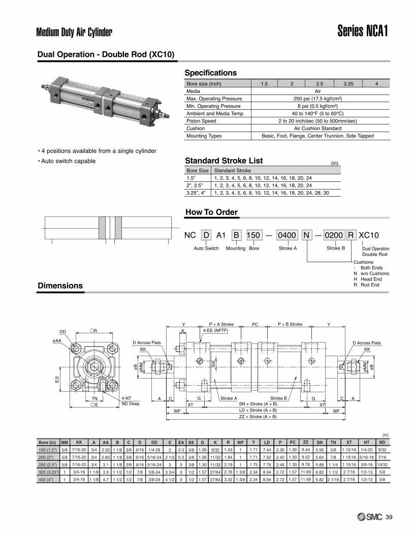
39
Medium Duty Air Cylinder Series NCA1
Bore (in)
150 (1.5")
200 (2")
250 (2.5")
325 (3.25")
400 (4")
MM
5/8
5/8
5/8
1
1
A
3/4
3/4
3/4
1 1/8
1 1/8
AA
2.02
2.60
3.1
3.9
4.7
B
1 1/8
1 1/8
1 1/8
1 1/2
1 1/2
LD
7.44
7.52
7.76
8.94
8.94
C
3/8
3/8
3/8
1/2
1/2
D
9/16
9/16
9/16
7/8
7/8
DD
1/4-28
5/16-24
5/16-24
3/8-24
3/8-24
E
2
2 1/2
3
3 3/4
4 1/2
EA
0.3
0.3
0
0
0
EE
3/8
3/8
3/8
1/2
1/2
G
1.26
1.26
1.30
1.57
1.57
K
9/32
11/32
11/32
27/64
27/64
ZZ
9.44
9.52
9.76
11.69
11.69
WF
1
1
1
1 3/8
1 3/8
R
1.43
1.84
2.19
2.76
3.32
Y
1.71
1.71
1.75
2.34
2.34
PC
1.30
1.30
1.30
1.57
1.57
P
2.36
2.40
2.48
2.72
2.72
XT
1 15/16
1 15/16
1 15/16
2 7/16
2 7/16
SN
5.56
5.64
5.88
6.82
6.82
TN
5/8
7/8
1 1/4
1 1/2
2 1/16
NT
1/4-20
5/16-18
3/8-16
1/2-13
1/2-13
ND
9/32
7/16
19/32
5/8
5/8
KK
7/16-20
7/16-20
7/16-20
3/4-16
3/4-16
(in)
EA
DD
øAA
K
XTXT
E/2
R
TNE
4-NTND Deep SN + Stroke (A + B)
D Across Flats
C
D Across Flats
KK
C
LD + Stroke (A + B)
KK
Stroke BStroke A
PCP + A Stroke P + B Stroke
WF
A
øB
øM
M
G
ZZ + Stroke (A + B)
Y
WF
A
øB
Y4-EE (NPTF)
øM
M
G
Dual Operation - Double Rod (XC10)
(in)Bore Size Standard Stroke1.5” 1, 2, 3, 4, 5, 6, 8, 10, 12, 14, 16, 18, 20, 24 2”, 2.5” 1, 2, 3, 4, 5, 6, 8, 10, 12, 14, 16, 18, 20, 243.25”, 4” 1, 2, 3, 4, 5, 6, 8, 10, 12, 14, 16, 18, 20, 24, 28, 30
Bore size (inch) 1.5 2 2.5 3.25 4 Media AirMax. Operating Pressure 250 psi (17.5 kgf/cm²)Min. Operating Pressure 8 psi (0.5 kgf/cm²)Ambient and Media Temp. 40 to 140°F (5 to 60°C)Piston Speed 2 to 20 inch/sec (50 to 500mm/sec)Cushion Air Cushion StandardMounting Types Basic, Foot, Flange, Center Trunnion, Side Tapped
Specifications
Standard Stroke List
How To Order
Auto Switch Mounting Bore Stroke A
Cushions- Both EndsN w/o CushionsH Head EndR Rod EndDimensions
NC D A1 B 150 — 0400 N — 0200 R XC10Stroke B Dual Operation
Double Rod
• 4 positions available from a single cylinder• Auto switch capable

40
Series NCA1 Medium Duty Air Cylinder
Bore (in)
150 (1.5")
200 (2")
250 (2.5")
325 (3.25")
400 (4")
MM
5/8
5/8
5/8
1
1
A
3/4
3/4
3/4
1 1/8
1 1/8
AA
2.02
2.60
3.1
3.9
4.7
B
1 1/8
1 1/8
1 1/8
1 1/2
1 1/2
XT
1 15/16
1 15/16
1 15/16
2 7/16
2 7/16
C
3/8
3/8
3/8
1/2
1/2
D
9/16
9/16
9/16
7/8
7/8
DD
1/4-28
5/16-24
5/16-24
3/8-24
3/8-24
E
2
2 1/2
3
3 3/4
4 1/2
EA
0.3
0.3
0
0
0
EE
3/8
3/8
3/8
1/2
1/2
G
1.26
1.26
1.3
1.57
1.57
J
1.1
1.06
1.06
1.18
1.18
PA
2.36
2.40
2.48
2.72
2.72
WF
1
1
1
1 3/8
1 3/8
NT
1/4-20
5/16-18
3/8-16
1/2-13
1/2-13
TN
5/8
7/8
1 1/4
1 1/2
2 1/16
LF
7.26
7.26
7.38
8.52
8.52
Y
1.71
1.71
1.75
2.34
2.34
SN
5.89
5.89
6.01
6.89
6.89
PB
2.40
2.44
2.52
2.76
2.76
PC
1.24
1.20
1.12
1.51
1.51
ZB
8.39
8.38
8.50
10.1
10.1
ND
9/32
7/16
19/32
5/8
5/8
KK
7/16-20
7/16-20
7/16-20
3/4-16
3/4-16
BA
1 1/8
1 1/8
1 1/8
1 1/2
1 1/2
Stroke B
øM
M
Y
G J
LF + Stroke A + Stroke B
ZB + Stroke A + Stroke B
4-EE (NPTF)
A
WF
øB
A
øB
KK
D AcrossFlats
Stroke A
PC PB + StrokePA + Stroke
E
4-NTND Deep
R
E/2
TN CSN + Stroke A + Stroke B
DD
XT
EA
øAA
R
1.43
1.84
2.19
2.76
3.32
Dual Operation - Single Rod (XC11)
(in)Bore Size Standard Stroke1.5” 1, 2, 3, 4, 5, 6, 8, 10, 12, 14, 16, 18, 20, 24 2”, 2.5” 1, 2, 3, 4, 5, 6, 8, 10, 12, 14, 16, 18, 20, 243.25”, 4” 1, 2, 3, 4, 5, 6, 8, 10, 12, 14, 16, 18, 20, 24, 28, 30
Specifications
Standard Stroke List
How To Order
Auto Switch Mounting Bore Stroke A
Cushions- Both EndsN w/o CushionsH Head EndR Rod End
Dimensions
NC D A1 B 150 — 0200 R + 0300 H XC11Stroke B-A Dual Operation
Single Rod
• 3 positions can be obtained from a single cylinder.• Twice the force is available for the extendedstroke.• Auto switch capable
Example: NCDA1B150-0200R+0300H-XC11 will stroke 2” then anadditional 3” for a total stroke of 5”. The front cylinder B (rod end)must be equal to 5” to allow the full stroke.
Bore size (inch) 1.5 2 2.5 3.25 4 Media AirMax. Operating Pressure 250 psi (17.5 kgf/cm²)Min. Operating Pressure 8 psi (0.5 kgf/cm²)Ambient and Media Temp. 40 to 140°F (5 to 60°C)Piston Speed 2 to 20 inch/sec (50 to 500mm/sec)Cushion Air Cushion StandardMounting Types Basic, Foot, Flange, Clevis Side Lug, Side Tapped

40-1
Medium Duty Air CylinderSeries NCA1NFPA Standard Piston Rod Threads (1.5" to 4" Bore)
Addition of NFPA Standard Threads for NCA1 Series
The NCA1 series is the NFPA Interchangeable tie-rod actuator and is available in bore sizes 1.5” to
8”.
Previously, the only standard rod thread option on NCA1 was a “Small Male” (Nil) thread. The new NFPA rod thread options being added are:
• Short Female (SF)• Intermediate Male (IM)• Flanged (F)• Full Male (FM)• Plain (PL)
Previously requesting the above rod thread changes required a RFS.See next page for dimensional information on these new NCA1 rod thread offerings.
The current NCA1 rod end standard is “Small Male” (Nil). The additional thread options, listed above,
are valid on the entire NCA1 series with the following exceptions:
• Not valid with K (non-rotating), W (double rod), M (male rod stud), KW (non-rotating, double rod)
• Not valid above cylinder stroke of 60.00”
• Not valid with J (Nylon Boot) or K (Neoprene Boot)
• Not valid with X-Options: XB7 (low temp), XC8 (adjustable stroke extension), XC11 (dual operation/singlerod), and X119US (non-rotating oversized rod)
For all questions, please contact your local SMC sales representative.

41
Series NCA1Medium Duty Air Cylinder
NFPA Standard Piston Rod Threads (1.5" to 4" Bore)
How To Order
NCNC D NC D A1A1A1 0400 – – Auto Switch Model
Mounting
Bore Size150200250325400
1.5"2"2.5"3.25"4"
• No. of Switches
Auto Switch Options
Rod Boot
Air Cushion
• •
•
•
–––––––––––––––
–––––––––––––––
–––––––––––––––
–––––––––––––––
–––––––––––––––
•
•
••
Stroke •
Options
–
Thread
Short Female (Threaded)Intermediate Male (Threaded)
––––––––––––––––––––––––––––––––––––––––––––––––––
– Small Male (SM)(Standard Threaded)–––––––––––––––––––––––––––––––––––––––––––––
––––––––––––––––––––––––––––––––––––––––––––––––––
•––––NilSFIM
FlangedFull Male (Threaded)Plain
––––––––––––––––––––––––––––––––––––––––––––––––––
––––––––––––––––––––––––––––––––––––––––––––––––––
FFMPL500
600800
5"6"8"
–––––––––––––––
–––––––––––––––
–––––––––––––––
––––––––––––––––––––––––––––––––––––––––––––––––––
––––––––––––––––––––––––––––––––––––––––––––––––––Note 1) Standard model cylinder (single rod) only Note 2) Changes only valid up to max 60.00" stroke Note 3) Changes not valid with: Rod Boot, XB7, XC8, XC11, or X119US
SHORT FEMALE (THREADED) - SF INTERMEDIATE MALE (THREADED) - IM
FLANGED - F FULL MALE (THREADED) -FM PLAIN - PL
SMALL MALE (THREADED) - Nil (SM) SMC STANDARD
Nil (SM) SF IM F FM PLKK KF
150 (1.5") 7/16-20 7/16-20 1/2-20 5/8-18 0.625 0.75 1.125 0.56 0.63 1.00 1.75 0.63 0.249 0.387/16-20 7/16-20 1/2-20 5/8-18 0.625 0.75 1.125 0.56 0.63 1.00 1.75 0.63 0.249 0.383/4-16 3/4-16 7/8-14 1-14 1.000 1.13 1.500 0.88 0.88 1.38 2.38 0.94 0.374 0.697/16-20 7/16-20 1/2-20 5/8-18 0.625 0.75 1.125 0.56 0.63 1.00 1.75 0.63 0.249 0.383/4-16 3/4-16 7/8-14 1-14 1.000 1.13 1.500 0.88 0.88 1.38 2.38 0.94 0.374 0.693/4-16 3/4-16 7/8-14 1-14 1.000 1.13 1.500 0.88 0.88 1.38 2.38 0.94 0.374 0.691-14 1-14 1 1/4-12 1 3/8-12 1.375 1.63 2.000 1.25 1.00 1.63 2.75 1.06 0.374 0.88
3/4-16 3/4-16 7/8-14 1-14 1.000 1.13 1.500 0.88 0.88 1.38 2.38 0.94 0.374 0.691-14 1-14 1 1/4-12 1 3/8-12 1.375 1.63 2.000 1.25 1.00 1.63 2.75 1.06 0.374 0.88
Note 1) Dimensions in grey are for oversized rod (XB5)
WFFor Flanged - F Only
WS AG AS MB
400 (4")
Bore Size (in) ØB D
200 (2")
250 (2.5")
325 (3.25")
Rod Thread
KKVF
AAF
ØMM
No Thread
No Thread

42
Series NCA1 Medium Duty Air Cylinder
Part No CB CD CE CH CW F L A KK ER
NY-150 0.765 0.5 1 1/2 1 1/2 1 3/4 3/4 7/16-20 1/2NY-325 1.265 0.75 2 3/8 1 3/8 5/8 1 1/4 1 1/4 1 1/8 3/4-16 3/4NY-800 1.515 1 3 1/8 1 1/2 3/4 1 1/2 1 1/2 1 5/8 1 -14 1NY-1000 2.032 1 3/8 4 1/8 2 1 2 2 1/8 2 1 1/4 -12 1 3/8NY-1200 2.531 1 3/4 4 1/2 2 3/8 1 1/4 2 3/8 2 1/4 2 1/4 1 1/2 -12 1 3/4NY-1400 2.531 2 5 1/2 2 15/16 1 1/4 2 15/16 2 1/2 3 1 7/8 -12 2NY-1401 3.032 2 1/2 6 1/2 3 1/2 1 1/2 3 1/2 3 3 1/2 2 1/4 -12 2 1/2NY-1402 3.032 3 6 3/4 3 7/8 1 1/2 3 7/8 3 1/4 3 1/2 2 1/2 -12 2 3/4
Part No CB CD DD E F FL LR M MR R
NCA1-P150 3/4 1/2 13/32 2 1/2 3/8 1 1/8 3/4 1/2 9/16 1.63NCA1-P325 1 1/4 3/4 17/32 3 1/2 5/8 1 7/8 1 1/4 3/4 7/8 2.56NCA1-P800 1 1/2 1 21/32 4 1/2 3/4 2 1/4 1 1/2 1 1 1/4 3.25NCA1-P1000 2 1 3/8 21/32 5 7/8 3 2 1/8 1 3/8 1 5/8 3.81NCA1-P1200 2 1/2 1 3/4 29/32 6 1/2 7/8 3 1/8 2 1/4 1 3/4 2 1/8 4.95NCA1-P1400 2 1/2 2 1 1/16 7 1/2 1 3 1/2 2 1/2 2 2 7/16 5.75NCA1-P1401 3 2 1/2 1 3/16 8 1/2 1 3/4 4 3/4 2 5/8 2 1/2 3 6.58NCA1-P1402 3 3 1 5/16 9 1/2 2 5 1/4 2 7/8 2 3/4 3 1/4 7.50
Note: Pivot Pin is not included.
Eye Brackets
Clevis Brackets
Part No CD CL
NCA1-150 1/2 1 7/8NCA1-325 3/4 2 5/8NCA1-800 1 3 1/8NCA1-1000 1 3/8 4 1/8NCA1-1200 1 3/4 5 1/8NCA1-1400 2 5 1/8NCA1-1401 2.5 6.19NCA1-1402 3 6.25
Note: Retainer Rings are included.
Pivot Pin
Order to Match Rod ThreadRod Eyes
Rod Clevises
øCD2
øC
D1
CP
CL
Pivot Pin
Accessories
Part No CD1 CD2 CL CP
NCDP-150 .500 0-.002 .106 2.28 1.94
NCDP-325 .750 0-.002 .140 3.10 2.72
Note: Cotter Pins are included.
Part No AA BA CB CD CW DD E F FL LR M MR
NCA1-CB150 2.3 1 5/8 0.785 1/2 1/2 3/8 -24 2 1/2 3/8 1 1/8 1/2 1/2 9/16NCA1-CB325 3.6 2 9/16 1.265 3/4 5/8 1/2 -20 3 1/2 5/8 1 7/8 1 1/16 3/4 1 1/16NCA1-CB800 4.6 3 1/4 1.515 1 3/4 5/8 -18 4 1/2 3/4 2 1/4 1 1/4 1 1 1/8NCA1-CB1000 5.4 3 13/16 2.032 1 3/8 1 5/8 -18 5 7/8 3 1 7/8 1 3/8 1 3/4NCA1-CB1200 7 4 15/16 2.531 1 3/4 1 1/4 7/8 -14 6 1/2 7/8 3 1/8 2 1 3/4 1 7/8NCA1-CB1400 8.1 5 3/4 2.531 2 1 1/4 1-14 7 1/2 1 3 1/2 2 1/8 2 2 1/8NCA1-CB1401 9.3 6 19/32 3.032 2 1/2 1 1/2 1 1/8-12 8 1/2 1 4 2 5/8 2 1/2 2 1/2NCA1-CB1402 10.6 7 1/2 3.032 3 1 1/2 1 1/4-12 9 1/2 1 4 1/4 2 7/8 2 3/4 2 3/4
Note: Pivot Pin is not included.
Part No A CA CB CD ER KK
NI-150 3/4 1 1/2 3/4 1/2 5/8 7/16 20NI-325 1 1/8 2 1/16 1 1/4 3/4 7/8 3/4 -16NI-800 1 5/8 2 13/16 1 1/2 1 1 3/16 1-14NI-1000 2 3 7/16 2 1 3/8 1 9/16 1 1/4 -12NI-1200 2 1/4 4 2 1/2 1 3/4 2 1 1/2 -12NI-1400 3 5 2 1/2 2 2 1/2 1 7/8 -12NI-1401 3 1/2 5 13/16 3 2 1/2 2 13/16 2 1/4-12NI-1402 3 1/2 6 1/8 3 3 3 1/4 2 1/2-12

Connector Style
Pin arrangement
Applicable standards JIS C 4524, JIS C 4525, IEC 947-5-2, NECA 0402Impact resistant 300m/s2
IP degress of protection IP-67 (IEC529 standard)Insulation resistance 100MΩ or more at 500VDC meg.Withstand voltage 1500VAC 1 minute (between contacts), leakage current 1mA or less.
43
Medium Duty Air Cylinder Series NCA1
D -
How to Order Auto Switches
Wire Lead Type Connector Type
Lead wire lengthS 0.5 (m)M 1.0 (m)L 3.0 (m)
Connector typeA M8-3 pinsB M8-4 PinsD M12-4 Pins
2 pin––
–
Orange
M8-3pins M8-4pins M12-4pins
Sensor type
DC 2-wireDC 2-wirenon-polarDC 3-wire
DC 4-wire
Lead wire color Meaning of contact No.1 pin
Brown
–
Brown
Brown
3 pin–
Brown
Blue
Blue
4 pinBlue
Blue
BlackBlack
1 pinOUT (+)
–
DC (+)
DC (+)
2 pin––
–Diagnistic
Output
3 pin–
OUT (+)
DC (–)
DC (–)
4 pinOUT (–)
OUT (±)
OUT
OUT
2 1
3 4
ø10
31.4Lead wire length
Sensor
• Connector M8-3 pins / 4 pins
Sensor
ø14
44Lead wire length
M12-4 pins
Lead wire lengthNil 0.5 (m) (1.64 ft)L 3 (m) (9.84 ft)Z 5 (m) (16.4 ft)
D - PC
For standard part number pleasesee applicable auto switches onpage 41 to 47.
For standard part number pleasesee applicable auto switches onpage 41 to 47.
Auto Switch Mounting Bracket / Part No.
NBT-150 NBT-200 NBT-200 NBT-325 NBT-325
Bore Model No. 150 (1.5”) 200 (2”) 250 (2.5”) 325 (3/25”) 400 (4”)
D-A5, D-F5D-A6, D-J5
1 4
3
1 2
43

44
Series NCA1 Medium Duty Air Cylinder
Specifications
Dimensions
D-A5 (With indicator light)
PLC: Programmable Logic Controller
Auto switch model number
Application
Load voltage
Max. load current and range
Contact protection circuit
Internal voltage drop
Indicator light
D-A53
PLC
24VDC
5 to 50mA
None
24VDC
5 to 50mA
D-A54
Relay/PLC
100VAC
5 to 25mA
Built-in
200VAC
5 to 12.5mA
D-A56
IC circuit
4 to 8VDC
20mA
None
0.8V or less
D-A6 (Without indicator light)
Auto switch model number
Application
Load voltage
Max. load current
Contact protection circuit
Internal resistance
≤ 24V 200VAC
12.5mA
D-A67
PLC/IC circuit
Max. 24VDC
30mA
None
≤ 1Ω (Including 3m lead wire)
D-A64
Relay/PLC
100VAC
25mA
Built-in
≤ 10Ω
• Lead wire ––– Oilproof vinyl heavy insulation cable, ø4, 0.3mm2, 2 cores (Brown, Blue), 0.5m or ø4, 0.2mm2, 3 cores (Brown, Black, Blue), 0.5m
• Refer to common specifications and lead wire length on page 48.
2.4V
ON: When red light emitting diode
ACDC
50mA
Operation Range (l Dimension)
Actuator series1 1/2
.354
2
.393
2 1/2 3 1/4
.433
4
.433NCA1
(in)
Note: Average value at normal temperature including hysteresis. (Tolerance ± 30%)
Bore size
.433
Zener diode
Reed switch LED
ResistanceOUT(–)Blue (Black)
OUT(+)Brown (Red)
Zener diode
Reed switch
LED
Resistance
Choke coil
Surge absorber
OUT(–) to Blue (Black)
OUT(+) toBrown (Red)
LED
Ree
d sw
itch Resistance
Reverse flowprevent diode
OUTBlack (White)
DC(+)Brown (Red)
DC(–)Blue (Black)
Load
(+)
(–)
Pow
er v
olta
ge
Reed switch
Choke coil
Surge absorber
OUT( ) toBlue (Black)
OUT(±) toBrown (Red)
±
Reed switch
OUT(±)Brown (Red)
OUT( )Blue (Black)
±
Internal Circuit
( ): If not applicable for IEC Standard
D-A53
D-A54
D-A56
D-A64
D-A67
Grommet

45
Medium Duty Air Cylinder Series NCA1
Specifications
Dimensions
D-A59W (With indicator light)
PLC: Programmable Logic Controller
Auto switch model number
Application
Load voltage
Load current range
Contact protection circuit
Internal voltage drop
Indicator light
D-A59W
Relay/PLC
24VDC
5 to 40mA
Built-in
≤ 4V
Operating point: Red light emitting diodeSuitable operating point: Green light emitting diode
• Lead wire ––––– Oilproof vinyl heavy insulation cable, ø4, 0.3mm2, 2 cores (Brown, Blue), 0.5m
• Refer to common specifications and lead wire length on page 48.
Operation Range (l Dimension)
Actuator series1 1/2
.354
2
.393
3 1/4
.433
4
.433NCA1
(in)
Note: Average value at normal temperature including hysteresis. (Tolerance ± 30%)
Bore size2 1/2
.433
Choke coil
Zener diode
Maincircuit
ofswitch
Reed switch
LED
OUT(+)Brown (Red)
OUT(–)Blue (Black)
Internal Circuit
( ): If not applicable for IEC Standard
D-A59W
Indicator light/Operation
The suitable operating point can
be indicated with a green light.
(Red → Green ← Red)
Grommet

46
Series NCA1 Medium Duty Air Cylinder
Dimensions
∗D-J51 differs in the shape, most sensitive position and operation range from other switches.Contact SMC for the details.
Specifications
D-F5�/D-J5�PLC: Programmable Logic Controller
Auto switch model number
Wiring
Output
Application
Power voltage
Current consumption
Load voltage
Load current
Internal voltage drop
Current leakage
Indicator light
D-F59
NPN
≤ 28VDC
≤ 40mA
1.5V or less
D-F5P
PNP
≤ 80mA
0.8V or less
D-J59
24VDC Relay/PLC
24VDC (10 to 28VDC)
5 to 40mA
4V or less
≤ 0.8mA at 24VDC
D-J51
AC Relay/PLC
80 to 260VAC
5 to 80mA
14V or less
≤ 1mA at 100 VDC
≤ 1.5mA at 200VDC
3 wire
IC circuit/Relay/PLC
5/12/24VDC (4.5 to 28VDC)
≤ 10mA
≤ 100μA at 24VDC
ON: When red light emitting diode
2 wire
0.8V or less at 10mAof load current
• Lead wire ––– Oilproof vinyl heavy insulation cable, ø4, 0.3mm2, 3 cores (Brown, Black, Blue), 2 cores (Brown, Blue), 0.5m
• Refer to common specifications and lead wire length on page 48.
Operation Range (l Dimension)
Actuator series1 1/2
.354
2
.393
2 1/2
.433
3 1/4
.433
4
.433NCA1
(in)
Note: Average value at normal temperature including hysteresis. (Tolerance ± 30%)
Bore size
OUTBlack (White)
DC(+)Brown (Red)
DC(–)Blue (Black)
Mai
n C
ircui
tof
sw
itch
OUTBlack (White)
DC(+)Brown (Red)
DC(–)Blue (Black)
Mai
n C
ircui
tof
sw
itch
OUT(+)Brown (Red)
OUT(–)Blue (Black)
Mai
n C
ircui
tof
sw
itch
OUT(+)Brown (Red)
OUT(–)Blue (Black)
Mai
n C
ircui
tof
sw
itch
Internal Circuit
( ): If not applicable for IEC Standard
D-F59
D-F5P
D-J59
D-J51
Grommet

47
Medium Duty Air Cylinder Series NCA1
Grommet
The output signal can bedetected in an unsteadydetecting area.
Dimensions
Diagnostic Output Operation
The diagnostic output is detect-ed when detecting positionremains at unsteady area only,not available at the most suit-able operating area, that is tosay, diagnostic signal can beoutput only when the detectingposition is far from the suitableposition for normal operation.
Specifications PLC: Programmable Logic Controller
• Lead wire –––– Oilproof vinyl heavy insulation cable, ø4, 0.2mm2, 4 cores (Brown, Black, Orange, Blue), 0.5m
• Refer to common specifications and lead wire length on page 48.
D-F59FAuto switch model number
Wiring
Output
Diagnostic output
Application
Power voltage
Current consumption
Load voltage
Load current
Internal voltage drop
Current leakage
Indicator light
D-F59F
4 wire
NPN
Normal operation
IC circuit/Relay/PLC
5/12/24VDC (4.5 to 28VDC)
≤ 10mA
≤ 28VDC
≤ 40mA
≤ 1.5V (≤ 0.8V at 10mA)
≤ 100μA at 24VDC
Operating point: Red light emitting diode Suitable operating point: Green light emitting diode
OUT (Normal output)Black (White)
DC(+)Brown (Red)
DC(–)Blue (Black)
OUT(Diagnostic output)Orange (Yellow)
Mai
n C
ircui
tof
sw
itch
Internal Circuit
( ): If not applicable for IEC Standard
Operation Range (l Dimension)
Actuator series1 1/2
.354
2
.393
2 1/2
.433
3 1/4
.433
4
.433NCA1
(in)
Note: Average value at normal temperature including hysteresis. (Tolerance ± 30%)
Bore size

48
Series NCA1 Medium Duty Air Cylinder
Dimensions
Specifications
D-F5�W/D-J59W (With indicator light)
Auto switch model number
Wiring
Output
Application
Power voltage
Current consumption
Load voltage
Load current
Internal voltage drop
Current leakage
Indicator light
D-F59W
3 wire
IC circuit/Relay/PLC
5/12/24VDC (4.5 to 28VDC)
10mA
≤ 100μA at 24VDC
Operating point: Red light emitting diodeSuitable operating point: Green light emitting diode
D-J59W
2 wire
24VDC Relay/PLC
24VDC (10 to 28VDC)
5 to 40mA
≤ 4V
≤ 0.8mA at 24VDC
D-F5PW
PNP
≤ 80mA
≤ 0.8V
• Lead wire –––––– Oilproof vinyl heavy insulation cable, ø4, 0.3mm2, 3 cores (Brown, Black, Blue), 2 cores (Brown, Blue), 0.5m
• Refer to common specifications and lead wire length on page 48.
≤ 1.5V(≤ 0.8V at 10mA load current)
PLC: Programmable Logic Controller
NPN
≤ 28VDC
≤ 40mA
Operation Range (l Dimension)
Actuator series1 1/2
.354
2
.393
2 1/2
.433
3 1/4
.433
4
.433NCA1
(in)
Note: Average value at normal temperature including hysteresis. (Tolerance ± 30%)
Bore size
OUTBlack (White)
DC(+)Brown (Red)
DC(–)Blue (Black)
Mai
n ci
rcui
tof
sw
itch
OUT(+)Brown (Red)
OUT(–)Blue (Black)
Mai
n ci
rcui
tof
sw
itch
OUT(+)Brown (Red)
OUT(–)Blue (Black)
Mai
n ci
rcui
tof
sw
itch
Internal Circuit
( ): If not applicable for IEC Standard
D-F59W
D-F5PW
D-J59W
Indicator light/Operation
The suitable operating point can
be indicated with a green light.
(Red→Green←Red)
Grommet

49
Medium Duty Air Cylinder Series NCA1
Auto switch model number
Wiring
Output
Application
Power voltage
Current consumption
Load voltage
Load current
Internal voltage drop
Current leakage
Indicator light
D-F5BAL
2 wire
24VDC Relay/PLC
24VDC (10 to 28VDC)
≤ 5 to 40mA
≤ 4V
≤ 0.8mA at 24VDC
Operating point: Red light emitting diode Suitable operating point: Green light emitting diode
Specifications PLC: Programmable Logic Controller
• Lead wire –––––– Oilproof vinyl heavy insulation cable, ø4, 0.3mm2, 2 cores (Brown, Blue), 3m (Standard)
• Refer to common specifications and lead wire length on page 48.
D-F5BAL (With indicator light)
Dimensions
Operation Range (l Dimension)
Actuator series1 1/2
.354
2
.393
2 1/2
.433
3 1/4
.433
4
.433NCA1
(in)
Note: Average value at normal temperature including hysteresis. (Tolerance ± 30%)
Bore size
OUT(+)Brown (Red)
OUT(–)Blue (Black)
Mai
n ci
rcui
tof
sw
itch
Internal Circuit
( ): If not applicable for IEC Standard
Indicator light/Operation
Consult SMC if using coolant liquid other
than water based solution.
Water (coolant) resistant per-
formance
Grommet
PrecautionsPrecautions
Caution

50
Series NCA1 Medium Duty Air Cylinder
Specifications PLC: Programmable Logic Controller
D-F5NTL (With indicator light)
Auto switch model number
Wiring
Output
Output operation
Operation time
Off-delay time
Application
Power voltage
Current consumption
Load voltage
Load current
Internal voltage drop
Current leakage
Indicator light
D-F5NTL
3 wire
NPN
Off-delay
≤ 1ms
200±50ms
IC circuit/Relay/PLC
5/12/24VDC (4.5 to 28VDC)
≤ 10mA
≤ 28VDC
≤ 80mA
≤ 1.5V (≤ 0.8V at 10mA)
≤ 100μA at 24VDC
ON: When red light emitting diode
• Lead wire ––– Oilproof vinyl heavy insulation cable, ø4, 0.3mm2, 3 cores (Brown, Black, Blue), 3m (Standard)
• Refer to common specifications and lead wire length on page 48.
Timer Operation
Dimensions
Operation Range (l Dimension)
Actuator series1 1/2
.354
2
.393
2 1/2
.433
3 1/4
.433
4
.433NCA1
(in)
Note) Average value at normal temperature including hysteresis. (Tolerance ± 30%)
Bore size
OUTBlack (White)
DC(+)Brown (Red)
DC(–)Blue (Black)
Mai
n ci
rcui
tof
sw
itch
Internal Circuit
( ): If not applicable for IEC Standard
Detection of immediate positioning for high-speed cylinder
Detecting point dispersion occurs due to response time of PLC (sequencer); e. g. scanning. Ex.) Cylinder speed-1000 mm/sec. Sequencer response time-0.1 sec. Detecting point despersion-Within 100mm (=1000mm/sec. x 0.1sec.)Take PLC response time into consideration when using.
With built-in OFF-delay timer(200ms)
Grommet

51
Medium Duty Air Cylinder Series NCA1
Auto Switch Common Specifications
Auto switch style
Current leakage
Operating time
Shock resistance
Insulation resistance
Withstand voltage
Ambient temperature
Protective construction
Reed switch
None
1.2ms
300m/s2
1500VAC/min.(between lead wire and the case) Note 1)
Solid state switch
3-wire: 100 μA or less, 2-wire: 1mA or less
1ms or less Note 3)
1000m/s2
1000VAC/min.(between lead wire and the case)
50 M Ω or more at 500MVDC (between lead wire and the case)
–10 to 60˚C
IEC529 Standard IP67,Waterproof construction (JISC0920) Note 2)
Note 1) Connector style (D-A73C/A80C/C73C/C80C) and D-9/9�A/A9/A9�V style: 1000VAC/min. (between lead wire and the case)Note 2) IEC529 Standard IP63, Rainproof construction (JISC0920) for Terminal conduit style (D-A3/A3�A/A3�C/G39/G39A/G39C/K39/K39A/K39C) and DIN teminal
style (D-A44/A44A/A44C).Note 3) Except solid state switch with timer (D-M5�TL, G5NTL, F7NTL, F5NTL) and Auto switch for strong magnetic field resistance (D-P5DWL).
D-J51: 5ms or less
Part No.
D-LC05
D-LC30
D-LC50
Lead wire length
0.5m
3m
5m
Part No. of lead wire with connector(Available for connector style only.)
D-A73• Lead wire length
Nil
L
Z
N∗
0.5m3m5m
None
∗ Applicable for the connector style (D- ∗∗ C) only
L
• Applicable auto switch with 5 meter lead wire ("Z") Reed switch: D-B53/B54, D-C73 (C)/C80C, D-A73(C)(H)/A80C, D-A53/A54, D-Z73, D-90/97/90A/93ASolid state switch: Manufactured upon receipt of order as standard (Except D-F9/F9lV)
• The standard lead wire length of solid state switch with timer or with water resistant 2-color indication is 3 meters. (Not available 0.5m)
• The standard lead wire length of strong magnetic field resistant solid state switch is 3 or 5 meters. (Not available 0.5m)
Lead Wire Length
Auto Switch Specification

52
Series NCA1
Safety Instructions
Note 1) ISO 4414: Pneumatic fluid power -- Recommendations for the application of equipment to transmission and control systems
Note 2) JIS B 8370: General Rules for Pneumatic Equipment
Warning
Caution : Operator error could result in injury or equipment damage.
Warning : Operator error could result in serious injury or loss of life.
Danger : In extreme conditions, there is a possible result of serious injury or loss of life.
These safety instructions are intended to prevent a hazardous situation and/or equipment damage. These instructions indicate the level of potential hazard by a label of "Caution", "Warning" or "Danger". To ensure safety, be sure to observe ISO 4414 Note 1), JIS B 8370 Note 2) and other safety practices.
1. The compatibility of pneumatic equipment is the responsibility of the person
who designs the pneumatic system or decides its specifications.
Since the products specified here are used in various operating conditions, their compatibility for the specific pneumatic system must be based on specifications or after analysis and/or tests to meet your specific requirements.
2. Only trained personnel should operate pneumatically operated machinery and
equipment.
Compressed air can be dangerous if handled incorrectly. Assembly, handling or repair of pneumatic systems should be performed by trained and experienced operators.
3. Do not service machinery/equipment or attempt to remove components until
safety is confirmed.
1. Inspection and maintenance of machinery/equipment should only be performed after confirmation of safe locked-out control positions.
2. When equipment is to be removed, confirm the safety process as mentioned above. Cut the supply pressure for this equipment and exhaust all residual compressed air in the system.
3. Before machinery/equipment is restarted, take measures to prevent shooting-out of cylinder piston rod, etc. (Bleed air into the system gradually to create back pressure.)
4. Contact SMC if the product is to be used in any of the following conditions:
1. Conditions and environments beyond the given specifications, or if product is used outdoors.2. Installation on equipment in conjunction with atomic energy, railway, air navigation, vehicles, medical
equipment, food and beverages, recreation equipment, emergency stop circuits, press applications, or safety equipment.
3. An application which has the possibility of having negative effects on people, property, or animals, requiring special safety analysis.

Series NCA1Actuator Precautions 1Be sure to read before handling.
53
1. Check the specifications.The products featured in this catalog are designed for used in indus-trial compressed air systems. If the products are used in conditionswhere pressure and /or temperature are outside range of specifica-tion, damage and/or malfunction may be occur. Do not use in theseconditions. (Refer to specifications.)Consult SMC if you use a fluid other than compressed air.
2. Intermediate stopsWhen intermediate stopping of a cylinder piston is performed with a 3position closed center type directional control valve, it is difficult toachieve stopping positions as accurate and precise as with hydraulicpressure due to the compressibility of air.Furthermore, since valves and cylinders, etc., are not guaranteed forzero air leakage, it may not be possible to hold a stopped position foran extended period of time. Contact SMC in case it is necessary tohold a stopped position for an extended period.
1. Operate within the limits of the maximumusable stroke.The piston rod will be damaged if operated beyond the maximumstroke. Refer to the cylinder model selection procedure for the maxi-mum useable stroke.
2. Operate the piston within a range such thatcollision damage will not occur at the strokeend.The operation range should prevent damage from occurring when apiston, having inertial force, stop by striking the cover at the strokeend. Refer to the cylinder model selction prcedure for the maximumusable stroke.
3. Use a speed controller to adjust the cylinderdrive speed, gradually increasing from a lowspeed to the desired speed setting.
4. Provide intermediate supports for long strokecylinders.An intermediate support should be provided in orderto prevent dam-age to a cylinder having a long stroke, due to problems suc as sag-ging of the rod deflection of the cylinder tube. vibration adn externalload.
1. There is a possibiliy of danger of sudden actionby air cylinders if sliding parts of machinery aretwisted,due to external forces, etc.In such cases, human injury may occur; e.g., by catching hands or feetin the machinery, or damage to the machinery itself may occur.Therefore, the machine should be adjusted to operate smoothly anddesigned to avoid such dangers.
2. A protective cover is recommeded to minimizethe risk of personal injury.If a stationary object and moving parts of a cylinder are in close prox-imity, personal injury may occur. Design the structure to avoid contactwith the human body.
3. Securely tighten all stationary parts and con-nected parts so that they will not become loose.Especially when a cylinder operates with high frequency or is installedwhere there is a lot of vibration, ensure that all parts remain secure.
4. A deceleration circuit or shock may be required.When a driven object is operated at high speed or the load is heavy, acylinder’s cushion will not be sufficient to absorb the impact. Install adeceleration circuit to reduce the speed before cushioning, or install anexternal shock absorber to relieve the impact. In this case, the rigidityof the machinery should also be examined.
5. Consider a possible drop in circuit pressuredue to a power outage, etc.When a cylinder is used in a clamping mechanism, there is a dangerof work pieces dropping if there is a decrease in clamping force due toa drop in circuit pressure caused by a power outage, etc. Therefore,safety equipment should be installed to prevent damage to machineryand/or human injury. Suspension mechanisms and lifting devices alsorequire consideration for drop prevention.
6. Consider a possible loss of power source.Measures should be taken to protect against boduly injury and equip-ment damage in the event that there is a loss of power to equipmentcontrolled by pneumatics, electricity or hydraulics, etc.
7. Design circuit that will prevent the driven objectfrom shooting out.The driven object will shoot out at a high speed if one sde of the cylin-der is pressurized after the air inside the cylinder is exhausted; forexample, when the cylinder is driven with exhaust center directionalcontrol valves or when it is started after the residual pressure inside thecircurt is exhausted.Such an event can possibly lead to bodily injury, by, for example catch-ing in human limbs, or damge to the machinery. Threfore, slect equip-ment and design circuits to prevent shoot-outs.
8. Consider emergency stops.Design so that human injury and/or damage to machinery and equipmentwill not be caused when machinery is stopped by a safety device underabnormal conditions, a power outage or a manual emergency stop.
9. Consider the action when operation is restartedafter an emergency stop or abnormal stop.Design the machinery so that human injury or equipment damage willnot occur upon restart of operation. When the cylinder has to be resetat the starting position, install safe manual control equipment.
Warning Warning
Caution
SelectionDesign

Series NCA1Actuator Precautions 2Be sure to read before handling.
54
1. Be certain to match the rod shaft center withthe load and direction of movement when con-necting.When not properly matched, problem may arise with the rod andtube, and damage may be caused due to friction on areas such asthe inner tube surface, bushings, rod surface, and seals.
2. When an external guide is used, connect therod end and the load in such a way that thereis no interference at any point within thestroke.
3. Do not scratch or gouge the sliding parts ofthe cylinder tube or piston rod by striking orgrasping them with other objects.Cylinder bores are manufactured to precise tolerances, so that evena slight deformation may cause faulty operation. Moveover scratches or gouges, etc., in the piston rod may lead todamaged seals and cause air leakage.
4. Prevent the seizure of rotating parts.Prevent the seizure of rotating parts (pins, etc.) by applying grease.
5. Do not use until you can verify that equipmentcan operate properly.After mounting, repairs, or modificatio, etc., connect the air supplyand electric power, and then confirm proper mounting by measns ofappropiate function and leak tests.
6. Instruction manualThe product should be mounted and operated after thr instructionmanual is thoroughly read and its conterns are undrstood.Keep the instruction manual where it can be referred to as need-ed.
1. Preparation before pipingBefore piping is connected, it should be thoroughly blown out withair (flushing) or washed to remove chips, cutting oil and otherdebris from inside the pipe.
2. Wrapping of pipe tapeWhen screwing together pipes and fittings, etc., be certain thatchips from the pipe threads and sealing material do not get insidethe piping.Also, when sealant tape is used, leave 1.5 to 2 thread ridgesexposed at the end of the threads.
Cushion
1. Readjust using the cushion needle.Cushions are adjusted at the time of shipment, however, the cush-ion needle on the cover should be readjusted when the product isput into service, based upon factors such as the size of the loadand the operating speed. When the cushion needle is turnedclockwise, the restriction becomes smaller and the cushion'seffectiveness is increased. Tighten the lock nut securely afteradjustment is performed.
2. Do not use the cushion needle fully closed.This will cause damage to the seals.
Caution
Mounting
Wrapping direction
Sealant tape
Expose approx. 2 threads
1. Use clean air.Do not use compressed air which includes chemicals, syntheticoils containing organic solvents, salt or corrosive gases, etc., as itcan cause damage or malfunction.
1. Install air filters.Install air filters at the upstream side of valves. The filtrationdegree should be 5μm or finer.
2. Install an after cooler, air dryer or water sep-arator, etc.Air that includes excessive drainage may cause malfunction ofvalves and other pneumatic equipment. To prevent this, install anafter cooler, air dryer or water separator, etc.
3. Use the product within the specified range offluid and ambient temperature.Take measures to prevent freezing, since moisture in circuits canbe frozen under 5°C, and this may cause damage to seals andlead to malfunction.Refer to SMC’s “Air Cleaning Equipment” catalog for furtherdetails on compressed air quality.
Warning
Caution
Caution
Maintenance
Warning1. Removal of equipment, and supply/exhaust
of compressed air.Before any machinery or equipment is removed, forst ensure thatthe appropriate measures are in place to prevent the fall or errat-ic movement of driven objects and eqipment, ten cut off t electricpower and reduce the pressure in thesystem to zero. Only thenshould you proceed with the removal of any machinery and equp-ment.When machinery is restarted, proceed with caution after confirm-ing measures to prevent cylinder lurching.
1. Drain flushingRemove drainage from air filters regularly. (Refer to specifica-tions.)
Caution

Series NCA1Auto Switch Precautions 1Be sure to read before handling.
55
1. Confirm the specifications.Read the specifications carefully and use this product appropri-ately. The product may be damaged or malfunction if it is usedoutside the range of specifications for current load, voltage, tem-perature or impact.
2. Take precautions when multiple cylinders areused close together.When multiple auto switch cylinders are used in close proximity,magnetic field interference may cause the switches to malfunction.Maintain a minimum cylinder separation of 40mm.
3. Pay attention to the length of time that aswitch is ON at an intermediate stroke posi-tion.When an auto switch is placed at an intermediate position of thestroke and a load is driven at the time the piston passes, the autoswitch will operate, but if the speed is too great the operating timewill be shortened and the load may not operate properly. The max-imum detectable piston speed is:
V (mm/s) = x 1000
4. Keep wiring as short as possible.<Reed switches>
As the length of the wiring to a load gets longer, the rush currentat switching ON becomes greater, and this may shorten the prod-uct’s life. (The switch will stay ON all the time.)Use a contact protection box when the wire length is 5m or longer.<Solid state switches>
Although wire length should not affect switch function, use a wire100m or shorter.
5. Pay attention to the internal voltage drop ofthe switch.<Reed switches>
1) Switches with an indicator light (Except D-Z76)• If auto switches are connected in series as shown below, take note
that there will be a large voltage drop because of internal resis-tance in the light emitting diodes. (Refer to internal voltage drop inthe auto switch specifications.)[The voltage drop will be “n” times larger when “n” auto switchesare connected.]Even though an auto switch operates normally, the load may notoperate.
Design & Selection
WarningWarning
Auto switch operating range (mm)____________________________Time load applied (ms)
• In the same way, when operating under a specified voltage,although an auto switch may operate normally, the load may notoperate. Therefore, the formula below should be satisfied afterconfirming the minimum operating voltage of the load.
2) If the internal resistance of a light emitting diode causes a problem,select a switch without an indicator light (Model D-Z80).<Solid state switches>
3) Generally, the internal voltage drop will be greater with a 2 wiresolid state auto switch than with a reed switch. Take the same pre-cautions as in 1).Also, note that a 12VDC relay is not applicable.
6. Pay attention to leakage current.<Solid state switches>
With a 2 wire solid state auto switch, current (leakage current)flows to the load to operate the internal circuit even when in theOFF state.
If the criteria given in the above formula are not met, it will notreset correctly (stays ON). Use a 3 wire switch if this specificationwill not be satisfied.Moreover, leakage current flow to the load will be “n” times largerwhen “n” auto switches are connected in parallel.
7. Do not use a load that generates surge volt-age.<Reed switches>
If driving a load such as a relay that generates a surge voltage,use a contact protection box. <Solid state switches>
Although a zener diode for surge protection is connected at theoutput side of a solid state auto switch, damage may still occur ifthe surge is applied repeatedly. When a load, such as a relay orsolenoid which generates surge is directly driven, use a type ofswitch with a built-in surge absorbing element.
8. Cautions for use in an interlock circuitWhen an auto switch is used for an interlock signal requiring highreliability, devise a double interlock system to avoid trouble by pro-viding a mechanical protection function, or by also using anotherswitch (sensor) together with the auto switch. Also perform periodic maintenance and confirm proper operation.
9. Ensure sufficient clearance for maintenanceactivities.When designing an application, be sure to allow sufficient clear-ance for maintenance and inspections.
Load
Supplyvoltage
Internal voltagedrop of switch
Minimum operatingvoltage of load– >
Operating current of load (OFF condition) > Leakage current

Series NCA1Auto Switch Precautions 2Be sure to read before handling.
56
5. Do not allow short circuit of loads.<Reed switches>
If the power is turned ON with a load in a short circuited condition,the switch will be instantly damaged because of excess currentflow into the switch.<Solid state switches>
All models of PNP output type switches do not have built-in shortcircuit protection circuits. Note that if a load is short circuited, the switch will be instantlydamaged as in the case of reed switches.
∗Take special care to avoid reverse wiring with the brown (red) powersupply line and the black (white) output line on 3 wire type switch-es.
6. Avoid incorrect wiring.<Reed switches>
A 24VDC switch with indicator light has polarity. The brown (red)lead wire is (+), and the blue (black) lead wire is (–).
1) If connections are reversed, a switch will operate, however, thelight emitting diode will not light up.Also note that a current greater than that specified will damage alight emitting diode and it will no longer operate.Applicable models: D-Z73<Solid state switches>
1) If connections are reversed on a 2 wire type switch, the switch willnot be damaged if protected by a protection circuit, but the switchwill always stay in an ON state. However, it is still necessary toavoid reversed connections, since the switch could be damaged bya load short circuit in this condition.
∗2)If connections are reversed (power supply line + and power supplyline –) on a 3 wire type switch, the switch will be protected by a pro-tection circuit. However, if the power supply line (+) is connected tothe blue (black) wire and the power supply line (–) is connected tothe black (white) wire, the switch will be damaged.
1. Do not drop or bump.Do not drop, bump or apply excessive impacts (300m/s² or more forreed switches and 1000m/s² or more for solid state switches) whilehandling. Although the body of the switch may not be damaged, theinside of the switch could be damaged and cause a malfunction.
2. Do not carry a cylinder by the auto switchlead wires.Never carry a cylinder by its lead wires. This may not only causebroken lead wires, but it may cause internal elements of the switchto be damaged by the stress.
3. Mount switches using the proper tighteningtorque.If a switch is tightened beyond the range of tightening torque, themounting screws or switch may be damaged. On the other hand, tightening below the range of tightening torquemay allow the switch to slip out of position. (Refer to switch mount-ing instructions for each series for switch mounting, moving, andtightening torque, etc.)
4. Mount a switch at the center of the operatingrange.Adjust the mounting position of an auto switch so that the pistonstops at the center of the operating range (the range in which aswitch is ON). (The mounting position shown in the catalog indi-cates the optimum position at stroke end.) If mounted at the end ofthe operating range (around the borderline of ON and OFF), oper-ation will be unstable.
Mounting & Adjustment Wiring
Wiring
Warning
1. Avoid repeatedly bending or stretching leadwires.Broken lead wires will result from repeatedly applying bendingstress or stretching force to the lead wires.
2. Be sure to connect the load before power isapplied.<2 wire type>
If the power is turned ON when an auto switch is not connected toa load, the switch will be instantly damaged because of excesscurrent.
3. Confirm proper insulation of wiring.Be certain that there is no faulty wiring insulation (contact withother circuits, ground fault, improper insulation between terminals,etc.). Damage may occur due to excess current flow into a switch.
4. Do not wire with power lines or high voltagelines.Wire separately from power lines or high voltage lines, avoidingparallel wiring or wiring in the same conduit with these lines.Control circuits containing auto switches may malfunction due tonoise from these other lines.
Warning
∗ Lead wire color changes
OldRed
Black
NewBrownBlue
Output (+)Output (–)
2 wire
OldRed
BlackWhite
NewBrownBlueBlack
Power supplyGNDOutput
3 wire
OldRed
BlackWhiteYellow
NewBrownBlueBlack
Orange
Power supplyGNDOutputDiagnostic output
Solid state with diagnostic output
OldRed
BlackWhite
Yellow
NewBrownBlueBlack
Orange
Power supply GNDOutputLatch typediagnostic output
Solid state with latchtype diagnostic output
Lead wire colors of SMC switches and related products have been changed in order to meet NECA (Nippon Electric Control Equip-ment Industries Association) Standard 0402 for production begin-ning September, 1996 and thereafter. Please refer to the tables provided.Special care should be taken regarding wire polarity during the time that the old colors still coexist with the new colors.
Warning
Series NCA1Auto Switch Precautions 3Be sure to read before handling.
57
1. Never use in an atmosphere of explosivegases. The structure of auto switches is not intended to prevent explosion.Never use in an atmosphere with an explosive gas since this maycause a serious explosion.
2. Do not use in an area where a magnetic fieldis generated.Auto switches will malfunction or magnets inside cylinders willbecome demagnetized. (Consult SMC regarding the availability ofa magnetic field resistant auto switch.)
3. Do not use in an environment where the autoswitch will be continually exposed to water.Although switches satisfy IEC standard IP67 construction (JIS C0920: watertight structure), do not use switches in applicationswhere continually exposed to water splash or spray. Poor insulationor swelling of the potting resin inside switches may cause malfunc-tion.
4. Do not use in an environment with oil orchemicals.Consult SMC if auto switches will be used in an environment withcoolant, cleaning solvent, various oils or chemicals. If auto switch-es are used under these conditions for even a short time, they maybe adversely affected by improper insulation, malfunction due toswelling of the potting resin, or hardening of the lead wires.
5. Do not use in an environment with tempera-ture cycles.Consult SMC if switches are used where there are temperaturecycles other than normal temperature changes, as there may beadverse effects inside the switches.
6. Do not use in an environment where there isexcessive impact shock.<Reed switches>
When excessive impact (300m/s2 or more) is applied to a reedswitch during operation, the contact point will malfunction and gen-erate or cut off a signal momentarily (1ms or less). Consult SMCregarding the need to use a solid state switch depending upon theenvironment.
7. Do not use in an area where surges are gen-erated.<Solid state switches>
When there are units (solenoid type lifter, high frequency inductionfurnace, motor, etc.) which generate a large amount of surge in thearea around cylinders with solid state auto switches, this maycause deterioration or damage to the switch. Avoid sources ofsurge generation and disorganized lines.
8. Avoid accumulation of iron waste or closecontact with magnetic substances.When a large amount of iron waste such as machining chips orspatter is accumulated, or a magnetic substance (somethingattracted by a magnet) is brought into close proximity with an autoswitch cylinder, it may cause the auto switch to malfunction due toa loss of the magnetic force inside the cylinder.
Operating Environment Maintenance
WarningWarning
1. Perform the following maintenance periodi-cally in order to prevent possible danger dueto unexpected auto switch malfunction.
1) Secure and tighten switch mounting screws.If screws become loose or the mounting position is dislocated,retighten them after readjusting the mounting position.
2) Confirm that there is no damage to lead wires.To prevent faulty insulation, replace switches or repair lead wires,etc., if damage is discovered.
3) Confirm the lighting of the green light on the 2 color indicator typeswitch.Confirm that the green LED is on when stopped at the establishedposition. If the red LED is on, the mounting position is not appro-priate. Readjust the mounting position until the green LED lightsup.
Other
Warning
1. Consult SMC concerning water resistance,elasticity of lead wires, and usage at weldingsites, etc.

Limited Cylinder Warranty - Terms and Conditions of Sale....
58
Series NCA1 Medium Duty Air Cylinder
SMC warrants that for 18 months or 1800 service miles*, whichev-er occurs first from date of purchase, it will replace or make adjust-ment at SMC’s option, of any defective cylinder sold if the cylinderproduct is returned with SMC’s prior written consent, transportationprepaid by the original buyer, and received by SMC at its place ofbusiness within the warranty period.
SMC shall have the right to inspect, prior to return, at the buyer’sfacility, any products claimed to be defective.
This warranty is limited exclusively to cylinder products which, in theopinion of SMC, have not been subjected to modification, misuse,negligence, misapplication, repairs or alterations. Damage caused byfire, theft, riot, explosion or acts of Gods are excluded
from this warranty. The foregoing constitutes the sole exclusive reme-dy of the buyer and the only liability of SMC and is in lieu of any andall other warranties, expressed or implied, or statutory as to mer-chantability, fitness for purpose sold, description, quality, productive-ness or any other matter. SMC shall not be liable for loss of use, orprofit, or special or consequential damages.
SMC assumes no responsibility for engineering technical advice per-taining to any manufactured item to which SMC’s products or goodshave been attached. No agent, employee, distributor, or representa-tive of SMC has the authority to extend the scope of this warranty orto make any other promises, warranties or guarantees concerning themanufacture, sale or application of SMC’s products.
*Service Miles = (inches/stroke) x (2 strokes/cycle) x (no of cycles) x [1 mile / 63,360 inches]
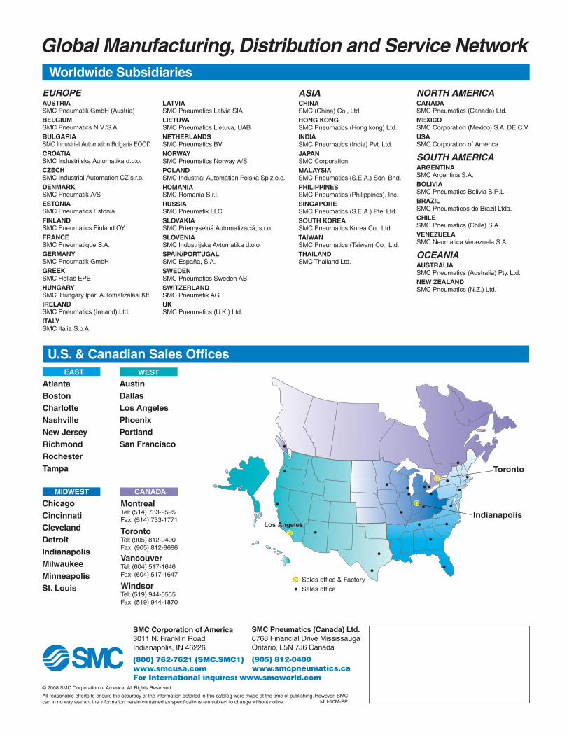
Global Manufacturing, Distribution and Service Network
EUROPEAUSTRIASMC Pneumatik GmbH (Austria)BELGIUMSMC Pneumatics N.V./S.A.BULGARIASMC Industrial Automation Bulgaria EOODCROATIASMC Industrijska Automatika d.o.o.CZECHSMC Industrial Automation CZ s.r.o.DENMARKSMC Pneumatik A/SESTONIASMC Pneumatics EstoniaFINLANDSMC Pneumatics Finland OYFRANCESMC Pneumatique S.A.GERMANYSMC Pneumatik GmbHGREEKSMC Hellas EPEHUNGARYSMC Hungary Ipari Automatizálási Kft.IRELANDSMC Pneumatics (Ireland) Ltd.ITALYSMC Italia S.p.A.
LATVIASMC Pneumatics Latvia SIALIETUVASMC Pneumatics Lietuva, UABNETHERLANDSSMC Pneumatics BVNORWAYSMC Pneumatics Norway A/SPOLANDSMC Industrial Automation Polska Sp.z.o.o.ROMANIA SMC Romania S.r.l.RUSSIA SMC Pneumatik LLC.SLOVAKIASMC Priemyselná Automatizáciá, s.r.o.SLOVENIASMC Industrijska Avtomatika d.o.o.SPAIN/PORTUGALSMC España, S.A.SWEDENSMC Pneumatics Sweden ABSWITZERLANDSMC Pneumatik AGUKSMC Pneumatics (U.K.) Ltd.
ASIACHINASMC (China) Co., Ltd.HONG KONGSMC Pneumatics (Hong kong) Ltd.INDIASMC Pneumatics (India) Pvt. Ltd.JAPANSMC CorporationMALAYSIASMC Pneumatics (S.E.A.) Sdn. Bhd.PHILIPPINESSMC Pneumatics (Philippines), Inc.SINGAPORESMC Pneumatics (S.E.A.) Pte. Ltd.SOUTH KOREASMC Pneumatics Korea Co., Ltd.TAIWANSMC Pneumatics (Taiwan) Co., Ltd.THAILANDSMC Thailand Ltd.
NORTH AMERICACANADASMC Pneumatics (Canada) Ltd.MEXICOSMC Corporation (Mexico) S.A. DE C.V.USASMC Corporation of America
SOUTH AMERICAARGENTINASMC Argentina S.A.BOLIVIASMC Pneumatics Bolivia S.R.L.BRAZILSMC Pneumaticos do Brazil Ltda.CHILESMC Pneumatics (Chile) S.A.VENEZUELASMC Neumatica Venezuela S.A.
OCEANIAAUSTRALIASMC Pneumatics (Australia) Pty. Ltd.NEW ZEALANDSMC Pneumatics (N.Z.) Ltd.
Worldwide Subsidiaries
U.S. & Canadian Sales Offices
AtlantaBostonCharlotteNashvilleNew JerseyRichmondRochesterTampa
AustinDallasLos AngelesPhoenixPortlandSan Francisco
ChicagoCincinnatiClevelandDetroitIndianapolisMilwaukeeMinneapolisSt. Louis
MontrealTel: (514) 733-9595Fax: (514) 733-1771
TorontoTel: (905) 812-0400Fax: (905) 812-8686
VancouverTel: (604) 517-1646Fax: (604) 517-1647
WindsorTel: (519) 944-0555Fax: (519) 944-1870
EAST
MIDWEST
WEST
CANADA
SMC Corporation of America3011 N. Franklin RoadIndianapolis, IN 46226
(800) 762-7621 (SMC.SMC1)www.smcusa.comFor International inquires: www.smcworld.com
SMC Pneumatics (Canada) Ltd.6768 Financial Drive MississaugaOntario, L5N 7J6 Canada
(905) 812-0400 www.smcpneumatics.ca
© 2008 SMC Corporation of America, All Rights Reserved.
All reasonable efforts to ensure the accuracy of the information detailed in this catalog were made at the time of publishing. However, SMC can in no way warrant the information herein contained as specifications are subject to change without notice.
Los AngelesIndianapolis
Toronto
Sales office & FactorySales office
MU-10M-PP

SeriesNCA1Air Cylinder NFPA InterchangeableLarge Bore Size
PDF239-E
• Medium duty 5", 6" and 8" bores
Features
• 11 different NFPA mounting options
• Standard with adjustable air cushion
• Auto switch capable

2
Series NCA1 CylinderLarge Bore
Contents
page
How to orderAuto SwitchesSpecificationsConstructionReplacement Kits
33455
Mounting styles
B MX0 basic styleBA MX1 tie rod extended - both endsBB MX2 tie rod extended - head endBC MX3 tie rod extended - rod cover endF MF1 rod side rectangular flangeG MF2 head side rectangular flangeL MS1 foot styleR MS2 side tapped styleS MS4 side lug styleX MP1 double head clevis styleD MP2 double detatchable head side clevis style
Dimension Changes (XB5, XC3 Options)
AccessoriesWarranty and Precautions
66778899
101011
11
1214

3

4
Series NCA1 CylinderLarge Bore
Maximum operating pressure 250 psi (1.75 Mpa)
Minimum operating pressure 8 psi (0.06 Mpa)

5
NoteAnodized
Electroless nickel platingPhosphate coated
Anodized
AnodizedAnodized
Nickel platingAnodized
Hard anodizedNickel plated
Zinc chromated
123456789
1011121314151617181920212223
ComponentRod cover
Cushion valveSnap ring
Cushion valve sealHead coverPiston rodCushion ACushion B
PistonPiston gasket
MagnetPiston sealWear ringJam nutGland
BushingCylinder tubeTie rod nut
Tie rodRod seal
Gland sealCushion seal
Cylinder tube gasket
MaterialAluminum alloy
Rolled steelSpring steel
NBRAluminum alloyCarbon steel
Aluminum alloyAluminum alloyAluminum alloy
NBR-
NBRResin
Rolled steelAluminum alloy
CompositeAluminum alloy
Rolled steelCarbon steel
NBRNBR
UrethaneNBR
Qty.1222111111
(1)111111841122
14 6
20
15
16
1918
21
123
17
7
10 9 12 1113 8
22 5
2
3
4
Component�part�
Con�tr��tion
NCA 500
Bore
500600800
Special options
NilXB5XB6XB7XB5B6XB5B7
StandardOversized rodHigh temperatureLow temperatureOversized W/ high temperatureOversized W/ low temperature
- -PS
Seal kits include the following parts:
1 - Rod seal1 - Piston seal1 - Gland seal2 - Cylinder tube gasket
* Cushion seal is not included for XB6, XB5B6, XB7, and XB5B7 over ø5" bore
2 - Cushion valve seal2 - Grease pack1 - Loctite 243
NCA 500
Bore
500600800
Special options
NilXB5XC35XB5C35
StandardOversized rodCoil scraperOversized W/ Coil scraper
- -RG
NCA 500
Bore
500600800
Stroke
(In inches and hundredths)
- -04 0400
NCA 500
Bore
500600800
Stroke
(In inches and hundredths)
Note: Tie rod length varies by mounting style.Quantity one set (4 pcs) of tie rods by mounting
- -11 0400B
Mounting
BBABBBCFG
LSRXD
Special options
NilXB5XB6XB7XB5B6XB5B7XC3
StandardOversized rodHigh temperatureLow temperatureOversized W/ high temperatureOversized W/ low temperatureStainless steel piston rod
NC A 500
Bore
500600800
Stroke
(In inches andhundredths)
- - -26A 0400D
Magnet
Nil - Non-MagnetD - With Magnet
�o��to��r�er��eal��it�
�o��to��r�er��lan���it�
�o��to��r�er�Cylin�er����e����o��le���tin����in�le��o�
�o��to��r�er��ie��o������o��le���tin����in�le��o� �o��to��r�er��i�ton��o�����em�ly����o��le���tin����in�le��o�
Gland kits Include:
1 - Gland1 - Gland seal2 - Grease pack
1 - Bushing1 - Rod seal1 - Loctite 243
Gland kits Include:
1 - Gland1 - Bushing* - Scraper with XC35

6
Series NCA1 CylinderLarge Bore
LF + Stroke
ZJ + Stroke A
WF
P + Stroke
ØB
ØM
M
2-EE
KK
E
TG
TH
ØAA 4-DD
Bore Size (in) ØMM KK A AA ØB DD E EE LF+ P+ TG TH WF ZJ+500 (5") 1.000 3/4-16 1.13 5.80 1.500 1/2-20 5.50 1/2NPT 4.50 2.88 4.10 2.75 1.38 5.88600 (6") 1.375 1-14 1.63 6.90 2.000 1/2-20 6.50 3/4 NPT 5.00 3.13 4.88 3.25 1.63 6.63800 (8") 1.375 1-14 1.63 9.10 2.000 5/8-18 8.50 3/4 NPT 5.13 3.25 6.44 4.25 1.63 6.75
Dimension Drawings
P + Stroke BB BB
ZJ + Stroke A
LF + Stroke WF
ØB
ØM
M
2-EE
KK
E
TG
TH
ØAA 4-DD
Bore Size (in) ØMM KK A AA ØB BB DD E EE LF+ P+ TG TH WF ZJ+500 (5") 1.000 3/4-16 1.13 5.80 1.500 1.81 1/2-20 5.50 1/2 NPT 4.50 2.88 4.10 2.75 1.38 5.88600 (6") 1.375 1-14 1.63 6.90 2.000 1.81 1/2-20 6.50 3/4 NPT 5.00 3.13 4.88 3.25 1.63 6.63800 (8") 1.375 1-14 1.63 9.10 2.000 2.31 5/8-18 8.50 3/4 NPT 5.13 3.25 6.44 4.25 1.63 6.75
MX0 - Basic style (B)
MX1 - Tie rod extended - both ends (BA)

7
BB P + Stroke
ØB
MM
A
WF LF + Stroke
ZJ + Stroke
2-EE
KK
E
TH
TG
ØAA 4-DD
Bore Size (in) ØMM KK A AA ØB BB DD EE LF+ P+ TG TH WF ZJ+500 (5") 1.000 3/4-16 1.13 5.80 1.500 1.81 1/2-20 1/2 NPT 4.50 2.88 4.10 2.75 1.38 5.88600 (6") 1.375 1-14 1.63 6.90 2.000 1.81 1/2-20 3/4 NPT 5.00 3.13 4.88 3.25 1.63 6.63800 (8") 1.375 1-14 1.63 9.10 2.000 2.31 5/8-18 3/4 NPT
E5.506.508.50 5.13 3.25 6.44 4.25 1.63 6.75
BB P + Stroke
ØB
MM
A
WF LF + Stroke
ZJ + Stroke
KK
2-EE
E
TG
TH
ØAA 4-DD
Bore Size (in) ØMM KK A AA ØB BB DD P+ TG TH WF ZJ+500 (5") 1.000 3/4-16 1.13 5.80 1.500 1.81 1/2-20 2.88 4.10 2.75 1.38 5.88600 (6") 1.375 1-14 1.63 6.90 2.000 1.81 1/2-20 3.13 4.88 3.25 1.63 6.63800 (8") 1.375 1-14 1.63 9.10 2.000 2.31 5/8-18
EE1/2 NPT3/4 NPT3/4 NPT
E5.506.508.50
LF+4.505.005.13 3.25 6.44 4.25 1.63 6.75
MX2 - Tie rod extended - head end (BB)
MX3 - Tie rod extended - rod cover end (BC)

8
Series NCA1 CylinderLarge Bore
P + Stroke W
WF
A
LF + Stroke
ZJ + Stroke
ØM
M
2-EE
KK
UF
TF
E
R
ØB
TH
4-FB
Bore Size (in) ØMM KK A ØB E EE ØFB LF+ P+ R TF TH UF W WF ZJ+500 (5") 1.000 3/4-16 1.13 1.500 5.50 1/2 NPT .50 4.50 2.88 4.10 6.63 2.75 7.63 .75 1.38 5.88600 (6") 1.375 1-14 1.63 2.000 6.50 3/4 NPT .50 5.00 3.13 4.88 7.63 3.25 8.63 .88 1.63 6.63
P + Stroke
ZF + Stroke
ZJ + Stroke
A
WF LF+ Stroke
ØB
ØM
M
2-EE
KK
UF
TF
TH
R
E
4-FB
ØMM KK A ØB E EE ØFB LF+ P+ R TF TH UF WF ZF+ ZJ+1.000 3/4-16 1.13 1.500 5.50 1/2 NPT .50 4.50 2.88 4.10 6.63 2.75 7.63 1.38 6.50 5.88
Bore Size (in)500 (5")600 (6") 1.375 1-14 1.63 2.000 6.50 3/4 NPT .50 5.00 3.13 4.88 7.63 3.25 8.63 1.63 7.38 6.63
Dimension Drawings
MF1 - Rod side rectangular flange (F)
MF2 - Head side rectangular flange (G)

9
P + Stroke
AO SA + Stroke AO
XA+ Stroke A
LF + Stroke WF
ØB
ØM
M
AT
2-EE
KK
E
S
AH
ØAB
Bore Size (in) ØMM KK A ØAB AH AO AT ØB E EE LF+ P+ S SA+ WF XA+500 (5") 1.000 3/4-16 1.13 .63 2.75 .63 .19 1.500 5.50 1/2 NPT 4.50 2.88 4.25 7.88 1.38 7.25600 (6") 1.375 1-14 1.63 .75 3.25 .63 .19 2.000 6.50 3/4 NPT 5.00 3.13 5.25 8.50 1.63 8.00800 (8") 1.375 1-14 1.63 .75 4.25 .69 .25 2.000 8.50 3/4 NPT 5.13 3.25 7.13 8.75 1.63 8.56
MS1 - Foot style (L)
MS2 - Side lug style (S)
XS SS + Stroke
P + Stroke
LF + Stroke WF A
ØB
ØM
M
2-EE
KK
TS
US
ST
LH
Bore Size (in) ØMM KK TS A ØB US ST EE LF+ XS SS+ P+ LH WF500 (5") 1.000 3/4-16 6.88 1.13 1.500 8.25 1.00 1/2 NPT 4.50 2.06 3.13 2.88 2.75 1.38600 (6") 1.375 1-14 7.88 1.63 2.000 9.25 1.00 3/4 NPT 5.00 2.31 3.63 3.13 3.25 1.63800 (8") 1.375 1-14 9.88 1.63 2.000 11.25 1.00 3/4 NPT 5.13 2.31 3.75 3.25 4.25 1.63
ØSB0.750.750.75
ØSB

10
Series NCA1 CylinderLarge Bore
XC + Stroke
P + Stroke
MR(MAX)
ØB
ØM
M
A
WF LF + Stroke
LR
2-EE
KK
E
UB
CB
CD
(ØPI
N)
TH
ØMM KK A ØB CB CD E EE LF+ LR MR P+ TH UB WF XC+1.000 3/4-16 1.13 1.500 1.280 .750 5.50 1/2 NPT 4.50 .94 .95 2.88 2.75 2.500 1.38 7.131.375 1-14 1.63 2.000 1.530 1.000 6.50 3/4 NPT 5.00 1.31 1.32 3.13 3.25 3.000 1.63 8.13
Bore Size (in)500 (5")600 (6")800 (8") 1.375 1-14 1.63 2.000 1.530 1.000 8.50 3/4 NPT 5.13 1.31 1.32 3.25 4.25 3.000 1.63 8.25
Note: Pivot and cotter pins are included.
Dimension Drawings
MS4 - Side tapped style (R)
MP1 - Double head clevis style (X)
LF + Stroke
ZJ + Stroke A SN + Stroke
WF
P + Stroke
XT
ØB
ØM
M
2-EE
KK
E TG TN
TH
ØAA 4-DD
4-NTDepth ND
Bore Size (in)500 (5")600 (6")800 (8")
ØMM1.0001.3751.375
KK3/4-161-141-14
A1.131.631.63
AA5.806.909.10
ØB1.5002.0002.000
DD1/2-201/2-205/8-18
E5.506.508.50
EE1/2NPT3/4NPT3/4NPT
LF+4.505.005.13
ND.75.88
1.13
NT5/8-113/4-103/4-10
P+2.883.133.25
SN+2.883.133.25
TG4.104.886.44
TH2.753.254.25
TN2.683.254.50
WF1.381.631.63
XT2.442.812.81
ZJ+5.886.636.75

11
ØB
ØM
M
A
P + Stroke
WF LF + Stroke
XD + Stroke
F
MRMAX
LR
KK
2-EE
E
TH
CB
UB
CD
(ØPI
N)
Bore Size (in) ØMM KK A ØB CB CD E EE F LF+ LR MR P+ TH UB WF XD+500 (5") 1.000 3/4-16 1.13 1.500 1.280 .750 5.50 1/2 NPT .63 4.50 .94 .95 2.88 2.75 2.500 1.38 7.75600 (6") 1.375 1-14 1.63 2.000 1.530 1.000 6.50 3/4 NPT .75 5.00 1.31 1.32 3.13 3.25 3.000 1.63 8.88800 (8") 1.375 1-14 1.63 2.000 1.530 1.000 8.50 3/4 NPT .75 5.13 1.31 1.32 3.25 4.25 3.000 1.63 9.00
Note: Pivot and cotter pins are included.
ZJ + Stroke
Rod end
Head end
Portstandardlocation
Cushionlocationstandard
How to Order: -XC3 Port Cushion
• Standard Part Number Location. AB (A=port, B=cushion)• Available on standard, XB5, XB6, XB7, XC6, and XC35• Ports and cushions in same location on rod and head ends• Standard available configurations: XC3BC, XC3CD, XC3DA, XC3AC, XC3DB, XC3AD, XC3BA, XC3CB, XC3DC• Ports and cushions NOT aligned between Rod and Head
ends available via RFS
Example: NCA1B500-0400-XC3BC (B = port, C = cushion)
A
WF
ØB
ØM
M
KK
E
TG
TH
ØAA 4-DD
Bore Size (in) ØMM KK A ØB WF ZJ+500 (5") 1.375 1-14 1.63 2.00 1.63 6.13600 (6") 1.75 1 1/4-12 2.00 2.375 1.88 6.88800 (8") 1.75 1 1/4-12 2.00 2.375 1.88 7.00
Standard Location = XC3AB• R (MS4) mount rotated ports available via RFS.• Available on standard, XB5, XB6, XB7, XC6, and XC35• Ports and cushions in same location on rod and head ends• Standard available configurations: XC3BC, XC3CD, XC3DA, XC3AC, XC3DB, XC3AD, XC3BA, XC3CB, XC3DC• Ports and cushions NOT aligned between Rod and Head
ends available via RFS
MP2 - Double detatchable head side clevis style (D)
Dimension changes for Options
Oversized rod (XB5 Option) Rotated Ports (XC3 Option)

11-1
E
TG
TH
ØAA 4-DD
Standard Location = XC3AB• R (MS4) mount rotated ports available via RFS.• Available on standard, XB5, XB6, XB7, XC6, and XC35• Ports and cushions in same location on rod and head ends• Standard available configurations: XC3BC, XC3CD, XC3DA, XC3AC, XC3DB, XC3AD, XC3BA, XC3CB, XC3DC• Ports and cushions NOT aligned between Rod and Head
ends available via RFS
Addition of NFPA Standard Threads for NCA1 Series
The NCA1 series is the NFPA Interchangeable tie-rod actuator and is available in bore sizes 1.5” to
8”.
Previously, the only standard rod thread option on NCA1 was a “Small Male” (Nil) thread. The new NFPA rod thread options being added are:
• Short Female (SF)• Intermediate Male (IM)• Flanged (F)• Full Male (FM)• Plain (PL)
Previously requesting the above rod thread changes required a RFS.See next page for dimensional information on these new NCA1 rod thread offerings.
The current NCA1 rod end standard is “Small Male” (Nil). The additional thread options, listed above,
are valid on the entire NCA1 series with the following exceptions:
• Not valid with K (non-rotating), W (double rod), M (male rod stud), KW (non-rotating, double rod)
• Not valid above cylinder stroke of 60.00”
• Not valid with J (Nylon Boot) or K (Neoprene Boot)
• Not valid with X-Options: XB7 (low temp), XC8 (adjustable stroke extension), XC11 (dual operation/singlerod), and X119US (non-rotating oversized rod)
For all questions, please contact your local SMC sales representative.

11-2
E
TG
TH
ØAA 4-DD
Standard Location = XC3AB• R (MS4) mount rotated ports available via RFS.• Available on standard, XB5, XB6, XB7, XC6, and XC35• Ports and cushions in same location on rod and head ends• Standard available configurations: XC3BC, XC3CD, XC3DA, XC3AC, XC3DB, XC3AD, XC3BA, XC3CB, XC3DC• Ports and cushions NOT aligned between Rod and Head
ends available via RFS
How To Order
NCNC D NC D A1A1A1 0400 – – Auto Switch Model
Mounting
Bore Size150200250325400
1.5"2"2.5"3.25"4"
• No. of Switches
Auto Switch Options
Rod Boot
Air Cushion
• •
•
•
–––––––––––––––
–––––––––––––––
–––––––––––––––
–––––––––––––––
–––––––––––––––
•
•
••
Stroke •
Options
–
Thread
Short Female (Threaded)Intermediate Male (Threaded)
––––––––––––––––––––––––––––––––––––––––––––––––––
– Small Male (SM)(Standard Threaded)–––––––––––––––––––––––––––––––––––––––––––––
––––––––––––––––––––––––––––––––––––––––––––––––––
•––––NilSFIM
FlangedFull Male (Threaded)Plain
––––––––––––––––––––––––––––––––––––––––––––––––––
––––––––––––––––––––––––––––––––––––––––––––––––––
FFMPL500
600800
5"6"8"
–––––––––––––––
–––––––––––––––
–––––––––––––––
––––––––––––––––––––––––––––––––––––––––––––––––––
––––––––––––––––––––––––––––––––––––––––––––––––––Note 1) Standard model cylinder (single rod) only Note 2) Changes only valid up to max 60.00" stroke Note 3) Changes not valid with: Rod Boot, XB7, XC8, XC11, or X119US
SHORT FEMALE (THREADED) - SF INTERMEDIATE MALE (THREADED) - IM
FLANGED - F FULL MALE (THREADED) -FM PLAIN - PL
SMALL MALE (THREADED) - Nil (SM) SMC STANDARD
Nil (SM) SF IM F FM PLKK KF
3/4-16 3/4-16 7/8-14 1-14 1.000 1.13 1.500 0.88 0.88 1.38 2.38 0.94 0.374 0.691-14 1-14 1 1/4-12 1 3/8-12 1.375 1.63 2.000 1.25 1.00 1.63 2.75 1.06 0.374 0.881-14 1-14 1 1/4-12 1 3/8-12 1.375 1.63 2.000 1.25 1.00 1.63 2.75 1.06 0.374 0.88
1 1/4 -12 1 1/4 -12 1 1/2-12 1 3/4-12 1.750 2.00 2.375 1.50 1.13 1.88 3.13 1.31 0.499 1.131-14 1-14 1 1/4-12 1 3/8-12 1.375 1.63 2.000 1.25 1.00 1.63 2.75 1.06 0.374 0.88
1 1/4 -12 1 1/4 -12 1 1/2-12 1 3/4-12 1.750 2.00 2.375 1.50 1.13 1.88 3.13 1.31 0.499 1.13Note 1) Dimensions in grey are for oversized rod (XB5)
No Thread
No Thread
KK
For Flanged - F Only
WS AG AS MB
Rod ThreadBore Size (in) ØMM
AAF
ØB D VF WF
500 (5")
600 (6")
800 (8")
NFPA STANDARD PISTON ROD THREADS (5" TO 8" BORE)

12
Series NCA1 CylinderLarge Bore
CB
1 1/41 1/2
2
CD
3/41
1 3/8
DD
17/3221/3221/32
E
3 1/24 1/2
5
F
5/83/47/8
FL
1 7/82 1/4
3
LR
1 1/41 1/22 1/8
M
3/41
1 3/8
MR
7/81 1/41 5/8
R
2.563.253.81
Part No.
NCA1-P325
NCA1-P800
NCA1-P1000
Dimensions
Note: Pivot pin is not included
Weight (lbs)
3.11
5.80
10.42
Weight (lbs)
2.79
5.45
9.89
Weight (lbs)
1.50
3.78
9.32
AA
3.64.65.4
BA
2 9/163 1/4
3 13/16
CB
1.2651.5152.032
CD
3/41
1 3/8
CW
5/83/41
DD
1/2-205/8-185/8-18
E
3 1/24 1/2
5
F
5/83/47/8
FL
1 7/82 1/4
3
LR
1 1/161 1/41 7/8
M
3/41
1 3/8
MR
1 1/161 1/81 3/4
Part No.
NCA1-CB325
NCA1-CB800
NCA1-CB1000
Dimensions
Note: Pivot pin is not included.
Note: Jam nut, pivot, and cotter pins are included.
CB
1.2651.5153.032
CD
0.751
1 3/8
CE
2 3/83 1/84 1/8
CH
1 3/81 1/2
2
CW
5/83/41
F
1 1/41 1/2
2
L
1 1/41 1/22 1/8
A
1 1/81 5/8
2
KK
3/4-161-14
1 1/4-12
ER
3/41
1 3/8
Part No.
NY-325
NY-800
NY-1000
Dimensions
Eye Bracket
Clevis Bracket
Rod Clevis
F M
ØCD
MR
FL
LR
ER
R E
CB
ØDD
F
FL
M
MR
ØCD
LR
ØDD
ER
AL
ØC
D
KK Tap through
E
E
BA
CBCW CW
AA
CE
CW CWCB
CH ØF

13
A1 1/81 5/8
2
CA2 1/16
2 13/163 7/16
CB1 1/41 1/2
2
CD3/41
1 3/8
ER7/8
1 3/161 9/16
KK3/4-161-14
1 1/4-12
Part No.NI-325NI-800
NI-1000
Dimensions
A3/4-161-14
1 1/4-12
B1 3/42 1/22 1/2
C2 5/162 15/162 15/16
D5/161/21/2
E1 1/81 5/81 5/8
F31/321 3/81 3/8
G7/8
1 1/41 1/4
H1 1/22 1/42 1/4
Part No.NCA1-AC325NCA1-AC800NCA1-AC1000
Dimensions
CD3/41
1 3/8
CL2 5/83 1/84 1/8
Part No.NCA1-325NCA1-800NCA1-1000
Dimensions
Note: Retainer rings are included.
CD3/41
1 3/8
DD.140.140.173
CL3.103.604.66
CP2.723.224.25
Part No.NCDP-325NCDP-800
NCDP-1000
Dimensions
Note: Cotter pins are included.
C1.2991.7322.165
F1 1/81 1/21 7/8
H27/6435/6423/32
Thread3/4-16UNF1-14UNF
1 1/4-12UNF
Part No.JM-10JM-800JM-1000
Dimensions
Dimensions per ASME B18.2.2 1987 (1999) Note: Jam nut is included.
Weight (lbs)0.391.042.37
Rod Eye
Alignment Coupler
Pivot Pins
Rod Jam Nut
CB
ØC
D
CL ØCD
F
C
Thread
CP ØDD
CE
ED
F Shank dia. G Across flat
ØB
H1/16 Radial float
1° Spherical motion
2xCD
CD
CA
ER
A
ØKK
CLØCD
A
A
H

14
Series NCA1 CylinderLarge Bore
Series NCA1Safety Instructions
Note 1) ISO 4414: Pneumatic fluid power -- Recommendations for the application of equipment to transmission and control systems
Note 2) JIS B 8370: General Rules for Pneumatic Equipment
Warning
Caution : Operator error could result in injury or equipment damage.
Warning : Operator error could result in serious injury or loss of life.
Danger : In extreme conditions, there is a possible result of serious injury or loss of life.
These safety instructions are intended to prevent a hazardous situation and/or equipment damage. These instructions indicate the level of potential hazard by a label of "Caution", "Warning" or "Danger". To ensure safety, be sure to observe ISO 4414 Note 1), JIS B 8370 Note 2) and other safety practices.
1. The compatibility of pneumatic equipment is the responsibility of the personwho designs the pneumatic system or decides its specifications.Since the products specified here are used in various operating conditions, their compatibility for thespecific pneumatic system must be based on specifications or after analysis and/or tests to meet yourspecific requirements.
2. Only trained personnel should operate pneumatically operated machinery andequipment.Compressed air can be dangerous if handled incorrectly. Assembly, handling or repair of pneumaticsystems should be performed by trained and experienced operators.
3. Do not service machinery/equipment or attempt to remove components untilsafety is confirmed.
1. Inspection and maintenance of machinery/equipment should only be performed after confirmation of safelocked-out control positions.
2. When equipment is to be removed, confirm the safety process as mentioned above. Cut the supplypressure for this equipment and exhaust all residual compressed air in the system.
3. Before machinery/equipment is restarted, take measures to prevent shooting-out of cylinder piston rod,etc. (Bleed air into the system gradually to create back pressure.)
4. Contact SMC if the product is to be used in any of the following conditions:1. Conditions and environments beyond the given specifications, or if product is used outdoors.2. Installation on equipment in conjunction with atomic energy, railway, air navigation, vehicles, medical
equipment, food and beverages, recreation equipment, emergency stop circuits, press applications, orsafety equipment.
3. An application which has the possibility of having negative effects on people, property, or animals,requiring special safety analysis.

15
Series NCA1Actuator Precautions 1Be sure to read before handling.
1. Check the specifications.The products featured in this catalog are designed for used in indus-trial compressed air systems. If the products are used in conditionswhere pressure and /or temperature are outside range of specifica-tion, damage and/or malfunction may be occur. Do not use in theseconditions. (Refer to specifications.)Consult SMC if you use a fluid other than compressed air.
2. Intermediate stopsWhen intermediate stopping of a cylinder piston is performed with a 3position closed center type directional control valve, it is difficult toachieve stopping positions as accurate and precise as with hydraulicpressure due to the compressibility of air.Furthermore, since valves and cylinders, etc., are not guaranteed forzero air leakage, it may not be possible to hold a stopped position foran extended period of time. Contact SMC in case it is necessary tohold a stopped position for an extended period.
1. Operate within the limits of the maximumusable stroke.The piston rod will be damaged if operated beyond the maximumstroke. Refer to the cylinder model selection procedure for the maxi-mum useable stroke.
2. Operate the piston within a range such thatcollision damage will not occur at the strokeend.The operation range should prevent damage from occurring when apiston, having inertial force, stop by striking the cover at the strokeend. Refer to the cylinder model selction prcedure for the maximumusable stroke.
3. Use a speed controller to adjust the cylinderdrive speed, gradually increasing from a lowspeed to the desired speed setting.
4. Provide intermediate supports for long strokecylinders.An intermediate support should be provided in orderto prevent dam-age to a cylinder having a long stroke, due to problems suc as sag-ging of the rod deflection of the cylinder tube. vibration adn externalload.
1. There is a possibiliy of danger of sudden actionby air cylinders if sliding parts of machinery aretwisted,due to external forces, etc.In such cases, human injury may occur; e.g., by catching hands or feetin the machinery, or damage to the machinery itself may occur.Therefore, the machine should be adjusted to operate smoothly anddesigned to avoid such dangers.
2. A protective cover is recommeded to minimizethe risk of personal injury.If a stationary object and moving parts of a cylinder are in close prox-imity, personal injury may occur. Design the structure to avoid contactwith the human body.
3. Securely tighten all stationary parts and con-nected parts so that they will not become loose.Especially when a cylinder operates with high frequency or is installedwhere there is a lot of vibration, ensure that all parts remain secure.
4. A deceleration circuit or shock may be required.When a driven object is operated at high speed or the load is heavy, acylinder’s cushion will not be sufficient to absorb the impact. Install adeceleration circuit to reduce the speed before cushioning, or install anexternal shock absorber to relieve the impact. In this case, the rigidityof the machinery should also be examined.
5. Consider a possible drop in circuit pressuredue to a power outage, etc.When a cylinder is used in a clamping mechanism, there is a dangerof work pieces dropping if there is a decrease in clamping force due toa drop in circuit pressure caused by a power outage, etc. Therefore,safety equipment should be installed to prevent damage to machineryand/or human injury. Suspension mechanisms and lifting devices alsorequire consideration for drop prevention.
6. Consider a possible loss of power source.Measures should be taken to protect against boduly injury and equip-ment damage in the event that there is a loss of power to equipmentcontrolled by pneumatics, electricity or hydraulics, etc.
7. Design circuit that will prevent the driven objectfrom shooting out.The driven object will shoot out at a high speed if one sde of the cylin-der is pressurized after the air inside the cylinder is exhausted; forexample, when the cylinder is driven with exhaust center directionalcontrol valves or when it is started after the residual pressure inside thecircurt is exhausted.Such an event can possibly lead to bodily injury, by, for example catch-ing in human limbs, or damge to the machinery. Threfore, slect equip-ment and design circuits to prevent shoot-outs.
8. Consider emergency stops.Design so that human injury and/or damage to machinery and equipmentwill not be caused when machinery is stopped by a safety device underabnormal conditions, a power outage or a manual emergency stop.
9. Consider the action when operation is restartedafter an emergency stop or abnormal stop.Design the machinery so that human injury or equipment damage willnot occur upon restart of operation. When the cylinder has to be resetat the starting position, install safe manual control equipment.
Warning Warning
Caution
SelectionDesign

16
Series NCA1 CylinderLarge Bore
Series NCA1Actuator Precautions 2Be sure to read before handling.
1. Be certain to match the rod shaft center withthe load and direction of movement when con-necting.When not properly matched, problem may arise with the rod andtube, and damage may be caused due to friction on areas such asthe inner tube surface, bushings, rod surface, and seals.
2. When an external guide is used, connect therod end and the load in such a way that thereis no interference at any point within thestroke.
3. Do not scratch or gouge the sliding parts ofthe cylinder tube or piston rod by striking orgrasping them with other objects.Cylinder bores are manufactured to precise tolerances, so that evena slight deformation may cause faulty operation. Moveover scratches or gouges, etc., in the piston rod may lead todamaged seals and cause air leakage.
4. Prevent the seizure of rotating parts.Prevent the seizure of rotating parts (pins, etc.) by applying grease.
5. Do not use until you can verify that equipmentcan operate properly.After mounting, repairs, or modificatio, etc., connect the air supplyand electric power, and then confirm proper mounting by measns ofappropiate function and leak tests.
6. Instruction manualThe product should be mounted and operated after thr instructionmanual is thoroughly read and its conterns are undrstood.Keep the instruction manual where it can be referred to as need-ed.
1. Preparation before pipingBefore piping is connected, it should be thoroughly blown out withair (flushing) or washed to remove chips, cutting oil and otherdebris from inside the pipe.
2. Wrapping of pipe tapeWhen screwing together pipes and fittings, etc., be certain thatchips from the pipe threads and sealing material do not get insidethe piping.Also, when sealant tape is used, leave 1.5 to 2 thread ridgesexposed at the end of the threads.
Cushion
1. Readjust using the cushion needle.Cushions are adjusted at the time of shipment, however, the cush-ion needle on the cover should be readjusted when the product isput into service, based upon factors such as the size of the loadand the operating speed. When the cushion needle is turnedclockwise, the restriction becomes smaller and the cushion'seffectiveness is increased. Tighten the lock nut securely afteradjustment is performed.
2. Do not use the cushion needle fully closed.This will cause damage to the seals.
CautionMounting
Wrapping direction
Sealant tapeExpose approx. 2 threads
1. Use clean air.Do not use compressed air which includes chemicals, syntheticoils containing organic solvents, salt or corrosive gases, etc., as itcan cause damage or malfunction.
1. Install air filters.Install air filters at the upstream side of valves. The filtrationdegree should be 5µm or finer.
2. Install an after cooler, air dryer or water sep-arator, etc.Air that includes excessive drainage may cause malfunction ofvalves and other pneumatic equipment. To prevent this, install anafter cooler, air dryer or water separator, etc.
3. Use the product within the specified range offluid and ambient temperature.Take measures to prevent freezing, since moisture in circuits canbe frozen under 5°C, and this may cause damage to seals andlead to malfunction.Refer to SMC’s “Air Cleaning Equipment” catalog for furtherdetails on compressed air quality.
Warning
Caution
Caution
Maintenance
Warning1. Removal of equipment, and supply/exhaust
of compressed air.Before any machinery or equipment is removed, forst ensure thatthe appropriate measures are in place to prevent the fall or errat-ic movement of driven objects and eqipment, ten cut off t electricpower and reduce the pressure in thesystem to zero. Only thenshould you proceed with the removal of any machinery and equp-ment.When machinery is restarted, proceed with caution after confirm-ing measures to prevent cylinder lurching.
1. Drain flushingRemove drainage from air filters regularly. (Refer to specifica-tions.)
Caution

17
Series NCA1Auto Switch Precautions 1Be sure to read before handling.
1. Confirm the specifications.Read the specifications carefully and use this product appropri-ately. The product may be damaged or malfunction if it is usedoutside the range of specifications for current load, voltage, tem-perature or impact.
2. Take precautions when multiple cylinders areused close together.When multiple auto switch cylinders are used in close proximity,magnetic field interference may cause the switches to malfunction.Maintain a minimum cylinder separation of 40mm.
3. Pay attention to the length of time that aswitch is ON at an intermediate stroke posi-tion.When an auto switch is placed at an intermediate position of thestroke and a load is driven at the time the piston passes, the autoswitch will operate, but if the speed is too great the operating timewill be shortened and the load may not operate properly. The max-imum detectable piston speed is:
V (mm/s) = x 1000
4. Keep wiring as short as possible.<Reed switches>
As the length of the wiring to a load gets longer, the rush currentat switching ON becomes greater, and this may shorten the prod-uct’s life. (The switch will stay ON all the time.)Use a contact protection box when the wire length is 5m or longer.<Solid state switches>
Although wire length should not affect switch function, use a wire100m or shorter.
5. Pay attention to the internal voltage drop ofthe switch.<Reed switches>
1) Switches with an indicator light (Except D-Z76)• If auto switches are connected in series as shown below, take note
that there will be a large voltage drop because of internal resis-tance in the light emitting diodes. (Refer to internal voltage drop inthe auto switch specifications.)[The voltage drop will be “n” times larger when “n” auto switchesare connected.]Even though an auto switch operates normally, the load may notoperate.
Design & Selection
WarningWarning
Auto switch operating range (mm)____________________________Time load applied (ms)
• In the same way, when operating under a specified voltage,although an auto switch may operate normally, the load may notoperate. Therefore, the formula below should be satisfied afterconfirming the minimum operating voltage of the load.
2) If the internal resistance of a light emitting diode causes a problem,select a switch without an indicator light (Model D-Z80).<Solid state switches>
3) Generally, the internal voltage drop will be greater with a 2 wiresolid state auto switch than with a reed switch. Take the same pre-cautions as in 1).Also, note that a 12VDC relay is not applicable.
6. Pay attention to leakage current.<Solid state switches>With a 2 wire solid state auto switch, current (leakage current)flows to the load to operate the internal circuit even when in theOFF state.
If the criteria given in the above formula are not met, it will notreset correctly (stays ON). Use a 3 wire switch if this specificationwill not be satisfied.Moreover, leakage current flow to the load will be “n” times largerwhen “n” auto switches are connected in parallel.
7. Do not use a load that generates surge volt-age.<Reed switches>If driving a load such as a relay that generates a surge voltage,use a contact protection box. <Solid state switches>Although a zener diode for surge protection is connected at theoutput side of a solid state auto switch, damage may still occur ifthe surge is applied repeatedly. When a load, such as a relay orsolenoid which generates surge is directly driven, use a type ofswitch with a built-in surge absorbing element.
8. Cautions for use in an interlock circuitWhen an auto switch is used for an interlock signal requiring highreliability, devise a double interlock system to avoid trouble by pro-viding a mechanical protection function, or by also using anotherswitch (sensor) together with the auto switch. Also perform periodic maintenance and confirm proper operation.
9. Ensure sufficient clearance for maintenanceactivities.When designing an application, be sure to allow sufficient clear-ance for maintenance and inspections.
Load
Supplyvoltage
Internal voltagedrop of switch
Minimum operatingvoltage of load– >
Operating current of load (OFF condition) > Leakage current

18
Series NCA1 CylinderLarge BoreSeries NCA1
Auto Switch Precautions 2Be sure to read before handling.
5. Do not allow short circuit of loads.<Reed switches>If the power is turned ON with a load in a short circuited condition,the switch will be instantly damaged because of excess currentflow into the switch.<Solid state switches>All models of PNP output type switches do not have built-in shortcircuit protection circuits. Note that if a load is short circuited, the switch will be instantlydamaged as in the case of reed switches.
∗Take special care to avoid reverse wiring with the brown (red) powersupply line and the black (white) output line on 3 wire type switch-es.
6. Avoid incorrect wiring.<Reed switches>A 24VDC switch with indicator light has polarity. The brown (red)lead wire is (+), and the blue (black) lead wire is (–).
1) If connections are reversed, a switch will operate, however, thelight emitting diode will not light up.Also note that a current greater than that specified will damage alight emitting diode and it will no longer operate.Applicable models: D-Z73<Solid state switches>
1) If connections are reversed on a 2 wire type switch, the switch willnot be damaged if protected by a protection circuit, but the switchwill always stay in an ON state. However, it is still necessary toavoid reversed connections, since the switch could be damaged bya load short circuit in this condition.
∗2)If connections are reversed (power supply line + and power supplyline –) on a 3 wire type switch, the switch will be protected by a pro-tection circuit. However, if the power supply line (+) is connected tothe blue (black) wire and the power supply line (–) is connected tothe black (white) wire, the switch will be damaged.
1. Do not drop or bump.Do not drop, bump or apply excessive impacts (300m/s2 or more forreed switches and 1000m/s2 or more for solid state switches) whilehandling. Although the body of the switch may not be damaged, theinside of the switch could be damaged and cause a malfunction.
2. Do not carry a cylinder by the auto switchlead wires.Never carry a cylinder by its lead wires. This may not only causebroken lead wires, but it may cause internal elements of the switchto be damaged by the stress.
3. Mount switches using the proper tighteningtorque.If a switch is tightened beyond the range of tightening torque, themounting screws or switch may be damaged. On the other hand, tightening below the range of tightening torquemay allow the switch to slip out of position. (Refer to switch mount-ing instructions for each series for switch mounting, moving, andtightening torque, etc.)
4. Mount a switch at the center of the operatingrange.Adjust the mounting position of an auto switch so that the pistonstops at the center of the operating range (the range in which aswitch is ON). (The mounting position shown in the catalog indi-cates the optimum position at stroke end.) If mounted at the end ofthe operating range (around the borderline of ON and OFF), oper-ation will be unstable.
Mounting & Adjustment Wiring
Wiring
Warning
1. Avoid repeatedly bending or stretching leadwires.Broken lead wires will result from repeatedly applying bendingstress or stretching force to the lead wires.
2. Be sure to connect the load before power isapplied.<2 wire type>If the power is turned ON when an auto switch is not connected toa load, the switch will be instantly damaged because of excesscurrent.
3. Confirm proper insulation of wiring.Be certain that there is no faulty wiring insulation (contact withother circuits, ground fault, improper insulation between terminals,etc.). Damage may occur due to excess current flow into a switch.
4. Do not wire with power lines or high voltagelines.Wire separately from power lines or high voltage lines, avoidingparallel wiring or wiring in the same conduit with these lines.Control circuits containing auto switches may malfunction due tonoise from these other lines.
Warning∗ Lead wire color changes
OldRed
Black
NewBrownBlue
Output (+)Output (–)
2 wireOldRed
BlackWhite
NewBrownBlueBlack
Power supplyGNDOutput
3 wire
OldRed
BlackWhiteYellow
NewBrownBlueBlack
Orange
Power supplyGNDOutputDiagnostic output
Solid state with diagnostic output
OldRed
BlackWhiteYellow
NewBrownBlueBlack
Orange
Power supply GNDOutputLatch typediagnostic output
Solid state with latchtype diagnostic output
Lead wire colors of SMC switches and related products have been changed in order to meet NECA (Nippon Electric Control Equip-ment Industries Association) Standard 0402 for production begin-ning September, 1996 and thereafter. Please refer to the tables provided.Special care should be taken regarding wire polarity during the time that the old colors still coexist with the new colors.
Warning

19
Series NCA1Auto Switch Precautions 3Be sure to read before handling.
1. Never use in an atmosphere of explosivegases. The structure of auto switches is not intended to prevent explosion.Never use in an atmosphere with an explosive gas since this maycause a serious explosion.
2. Do not use in an area where a magnetic fieldis generated.Auto switches will malfunction or magnets inside cylinders willbecome demagnetized. (Consult SMC regarding the availability ofa magnetic field resistant auto switch.)
3. Do not use in an environment where the autoswitch will be continually exposed to water.Although switches satisfy IEC standard IP67 construction (JIS C0920: watertight structure), do not use switches in applicationswhere continually exposed to water splash or spray. Poor insulationor swelling of the potting resin inside switches may cause malfunc-tion.
4. Do not use in an environment with oil orchemicals.Consult SMC if auto switches will be used in an environment withcoolant, cleaning solvent, various oils or chemicals. If auto switch-es are used under these conditions for even a short time, they maybe adversely affected by improper insulation, malfunction due toswelling of the potting resin, or hardening of the lead wires.
5. Do not use in an environment with tempera-ture cycles.Consult SMC if switches are used where there are temperaturecycles other than normal temperature changes, as there may beadverse effects inside the switches.
6. Do not use in an environment where there isexcessive impact shock.<Reed switches>When excessive impact (300m/s2 or more) is applied to a reedswitch during operation, the contact point will malfunction and gen-erate or cut off a signal momentarily (1ms or less). Consult SMCregarding the need to use a solid state switch depending upon theenvironment.
7. Do not use in an area where surges are gen-erated.<Solid state switches>When there are units (solenoid type lifter, high frequency inductionfurnace, motor, etc.) which generate a large amount of surge in thearea around cylinders with solid state auto switches, this maycause deterioration or damage to the switch. Avoid sources ofsurge generation and disorganized lines.
8. Avoid accumulation of iron waste or closecontact with magnetic substances.When a large amount of iron waste such as machining chips orspatter is accumulated, or a magnetic substance (somethingattracted by a magnet) is brought into close proximity with an autoswitch cylinder, it may cause the auto switch to malfunction due toa loss of the magnetic force inside the cylinder.
Operating Environment Maintenance
WarningWarning1. Perform the following maintenance periodi-
cally in order to prevent possible danger dueto unexpected auto switch malfunction.
1) Secure and tighten switch mounting screws.If screws become loose or the mounting position is dislocated,retighten them after readjusting the mounting position.
2) Confirm that there is no damage to lead wires.To prevent faulty insulation, replace switches or repair lead wires,etc., if damage is discovered.
3) Confirm the lighting of the green light on the 2 color indicator typeswitch.Confirm that the green LED is on when stopped at the establishedposition. If the red LED is on, the mounting position is not appro-priate. Readjust the mounting position until the green LED lightsup.
Other
Warning1. Consult SMC concerning water resistance,
elasticity of lead wires, and usage at weldingsites, etc.

SMC Corporation of America10100 SMC Blvd., Noblesville, IN 46060 www.smcusa.comSMC Pneumatics (Canada) Ltd.www.smcpneumatics.ca
(800) SMC.SMC1 (762-7621)e-mail: [email protected] International inquiries: www.smcworld.com
© 2015 SMC Corporation of America, All Rights Reserved.All reasonable efforts to ensure the accuracy of the information detailed in this catalog were made at the time of publishing. However, SMC can in no way warrant the information herein contained as specifications are subject to change without notice.
Limited warranty and Disclaimer/Compliance RequirementsThe product used is subject to the following “Limited warranty and Disclaimer” and “Compliance Requirements”.Read and accept them before using the product.
Limited warranty and Disclaimer1. The warranty period of the product is 1 year in service or 1.5 years after the product is delivered, whichever is first.Note)
Also, the product may have specified durability, running distance or replacement parts. Please consult your nearest sales branch.
2. For any failure or damage reported within the warranty period which is clearly our responsibility, a replacement product or necessary parts will be provided. This limited warranty applies only to our product independently, and not to any other damage incurred due to the failure of the product.
3. Prior to using SMC products, please read and understand the warranty terms and disclaimers noted in the specified catalog for the particular products.
Note) Vacuum pads are excluded from this 1 year warranty. A vacuum pad is a consumable part, so it is warranted for a year after it is delivered. Also, even within the warranty period, the wear of a product due to the use of the vacuum pad or failure due to the deterioration of rubber material are not covered by the limited warranty.
Compliance Requirements1. The use of SMC products with production equipment for the manufacture of weapons of mass destruction (WMD) or any other weapon is strictly prohibited.
2. The exports of SMC products or technology from one country to another are governed by the relevant security laws and regulations of the countries involved in the transaction. Prior to the shipment of an SMC product to another country, assure that all local rules governing that export are known and followed.