stage 3 - terminal expansion 27 june 2016 revision: b fire
TRANSCRIPT

Stage 3 - Terminal Expansion Fire Safety Study
Stolthaven Australia Pty Ltd
27 June 2016
Revision: B
Reference: 236974
Project 236974 File Rs236974 - Stolthaven NCT Stage 3 Fire Safety Study.docx 27 June 2016 Revision B
Document control record Document prepared by:
Aurecon New Zealand Limited Spark Central Level 8, 42-52 Willis Street Wellington 6011 PO Box 1591 Wellington 6140 New Zealand T F E W
+61 8 6145 9300 +61 8 6145 5020 [email protected] aurecongroup.com
A person using Aurecon documents or data accepts the risk of: a) Using the documents or data in electronic form without requesting and checking them for accuracy against the original hard
copy version. b) Using the documents or data for any purpose not agreed to in writing by Aurecon.
Document control
Report title Fire Safety Study
Document ID Project number 236974
File path C:\users\lisa.bayliss\desktop\rs236974 - Stolthaven NCT Stage 3 Fire Safety Study.docx
Client Stolthaven Australia Pty Ltd Client contact Paul Hayward
Rev Date Revision details/status Author Reviewer Verifier (if required)
Approver
A 10 June 2016 Draft for review M Willard D Martin/ Stolthaven
B 27 June 2016 Issued for Development Approval
M.Willard D.Martin Stolthaven J. Cockshott
D.Martin
Current revision B
Approval
Author signature
Approver signature
Name Matthew Willard Name Dan Martin
Title Associate Title Technical Director
Project 236974 File Rs236974 - Stolthaven NCT Stage 3 Fire Safety Study.docx 27 June 2016 Revision B Page i
Contents Executive summary 1 1 Introduction 3
1.1 Scope of work 3 1.2 Methodology 3 1.3 Limitations 4
2 Legislation, Standards and Codes of Practice 5 3 Facility Description 6
3.1 Location 6 3.2 Product receipt 6 3.3 Product transfer 7 3.4 Storage tanks 8 3.5 Secondary containment and drainage 8 3.6 Slops 9 3.7 Emergency Shut Down 1 3.8 Fire Alarms 1
4 Hazard Identification 2 4.1 Hazardous Materials 2 4.2 Bulk storage tanks 3 4.3 Road tanker loading operations 4 4.4 Pipework and pipelines 4
5 Scenarios 5 5.1 Design scenarios 5 5.2 Non-Design Scenarios 6
6 Consequence Effects Analysis 8 6.1 Heat radiation contours 8 6.2 Dispersion modelling 8
7 Risk reduction measures 12 7.1 General 12 7.2 Bulk storage tanks 13 7.3 Minor storage in tanks 14 7.4 Secondary containment 14 7.5 Product Inlet manifolds 15 7.6 Pump bank and product transfer pumps 15 7.7 Gantry operations 15
8 Fire Protection Systems 16 8.1 Water supply and storage 16 8.2 Bulk storage tanks 16

Project 236974 File Rs236974 - Stolthaven NCT Stage 3 Fire Safety Study.docx 27 June 2016 Revision B Page ii
8.3 Water distribution system 25 8.4 Road loading gantry 25 8.5 Vapour Recovery Unit 26 8.6 Gantry spill pit 26 8.7 Bunded area foam system 26 8.8 Minor storage / SLOPS area fire protection 27 8.9 Other 27
Appendices Appendix A
Drawings Appendix B
HAZOP 11045 Rev 1 Appendix C
Heat Radiation Exposure Appendix D
AS 1940 and Consequence Modelling Results

Project 236974 File Rs236974 - Stolthaven NCT Stage 3 Fire Safety Study.docx 27 June 2016 Revision B Page 1
Executive summary Stolthaven operates an existing fuel storage facility (Terminal) located on LOT 2 of the Port of Newcastle Bulk Liquids Precinct in Mayfield, Newcastle, New South Wales (NSW) Australia. The Terminal currently stores diesel, a combustible liquid.
Stolthaven are planning an expansion of the Terminal, known as Stage 3. The Stage 3 works will include the following:
Product receipt via a new wharfline from berth M7 to the existing Terminal and the new Stage 3 Terminal;
New flammable and combustible storage tanks;
Secondary containment for the new storage tank;
Tank inlet and discharge piping and pumping systems;
Product transfer to road tankers via a new six bay loading gantry;
Drainage systems;
A new site office, switchroom and expansion of the existing control room; and
New and expanded electrical and control systems, including SIL rated systems where appropriate; and
A new fire protection system.
When completed the site will operate on a 24/7 basis as a Major Hazard Facility. The site will be manned continuously by trained operators.
The objective of the Fire Safety Study (FSS) is to identify fire and explosion risk reduction measures that should be implemented as part of the Stage 3 Terminal, and to determine the minimum performance criteria for the design of the recommended fire fighting systems.
The FSS is based on the application of the NSW Department of Planning and Environment (DPE) Hazardous Industry Planning Advisory Paper (HIPAP) No. 2: Fire Safety Study Guidelines.
The performance criteria for the design of the fire fighting systems to be implemented is based on compliance with relevant Standards and Codes of Practice. Australian Standard, AS 1940 is the principle Standard that prescribes the minimum fire fighting infrastructure for terminals and is referenced throughout this document. In addition, other documents, such as the Energy Institute Model Code of Safe Practice Part 19: Fire precautions at petroleum refineries and bulk storage installations (EI IP-MCSP-P19) recommend a performance based approach to ensure that the fire fighting systems provided take into account local site conditions. An example of this is the use of heat radiation modelling using site meteorological conditions, tank geometry and products stored as the main variables to determine the requirements for the cooling of adjacent tanks. These results are then compared the results from the prescriptive AS 1940 Appendix J calculations.
A Preliminary Hazard Analysis (PHA) has been completed by others and is included in Appendix B.
A summary of the recommended fire and explosion risk reduction measures are summarised below:
Fire alarm and indication system based on the relevant sections of AS 1940 and AS 1670 (series);
A new connection to the Town water mains connection for automatic top up of the fire water tanks;

Project 236974 File Rs236974 - Stolthaven NCT Stage 3 Fire Safety Study.docx 27 June 2016 Revision B Page 2
Two new fire water storage tanks to be installed on LOT 36. Each tank will be sized for an effective capacity of 1.2 ML. The tanks will be connected and hydraulically balanced via a DN250 cross connection pipeline;
In order to balance the water demand with installed cost all Stage 3 tanks will be provided with fixed cooling rings, and fixed, self-oscillating monitors will be provided for the diesel storage tanks on LOT 2 that are at risk from the Stage 3 terminal;
Three new fire water pumps, nominally sized for 11,500 LPM at 10.5 bar g. Two pumps will operate in parallel with a third on stand by. The pumps will be diesel driven and housed in a pump house;
Cooling water will be applied to tanks at risk via fixed cooling rings for all Stage 3 tanks. Four tanks currently installed at the existing diesel terminal have been identified at risk of radiant heat exposure. Cooling water to these tanks will be applied via fixed, self-oscillating water cannons (monitors);
Foam to Stage 3 bulk storage tanks will be provided by Type II fixed foam pourers installed on the tanks. The flowrate and discharge time will be as per NFPA 11;
A new 7,200 L foam concentrate tank with alcohol resistant foam concentrate;
Two water coupled water motor proportioning systems (Turbinator MIDI-PLUS) for foam proportioning. One unit will be required for the bulk storage tank foam systems and both will operate for protection of the loading gantry;
The cooling and foam systems will be operated manually via a new control panel that will be located near the Stage 3 pump house. Feedback will be provided on the bulk tank foam systems to provide confirmation that the deluge valve has opened and that the line to the tank is pressurised. Feedback on the tank cooling systems operation will be visual. The control of the deluge valves will be electro-hydraulic utilising pressurised hydrant water to open and close the deluge valve. This is an inherently more reliable system than an air actuated system as there is one less process stream that could fail.
A hydrant ring main that encircles the three Stage 3 compounds and interconnecting branches between compounds. The hydrant ring main will be provided with isolation valves, dual outlet hydrant valves andDN150 Storz couplings (subject to agreement with the local fire brigade)
Road loading gantry fire protection system via fixed foam-water sprinkler system. The flowrate and discharge time will be as per NFPA 16.
The loading gantry fire protection systems will be automatically operated via flame detectors
Foam capable monitor for the protection of a VRU fire scenario;
Foam capable monitor for the protection of the additive / SLOPS compound tanks;
Bund foam pourers for the additive / SLOPS compound, Gantry Spill Pit and all flammable liquid storage tank intermediate bunds;
Signage and labelling, including a fire system block plan;
Maintenance, inspection and testing regime;
First aid and portable fire extinguishers; and
Pre-incident fire plans for specific fire scenarios.
Project 236974 File Rs236974 - Stolthaven NCT Stage 3 Fire Safety Study.docx 27 June 2016 Revision B Page 3
1 Introduction Stolthaven Australia Pty Ltd (Stolthaven) operates an existing Terminal located on LOT 2 of the Port of Newcastle Bulk Liquids Precinct in Mayfield, Newcastle, NSW Australia. The Terminal currently stores diesel, a combustible liquid.
Stolthaven are planning an expansion of the Terminal, known as Stage 3. The Stage 3 works will include the following:
Product receipt via a new wharfline from berth M7 to the existing Terminal and the new Stage 3 Terminal;
New flammable and combustible storage tanks;
Secondary containment for the new storage tanks;
Tank inlet and discharge piping and pumping systems;
Product transfer to road tankers via a new six bay loading gantry;
Drainage systems;
A new site office, switchroom and expansion of the existing control room; and
New and expanded electrical and control systems, including SIL rated systems where appropriate; and
A new fire protection system.
When completed the site will operate on a 24/7 basis as a Major Hazard Facility. The site will be manned continuously by trained operators.
Stolthaven have engaged Aurecon to prepare a Fire Safety Study (FSS) for the Stage 3 terminal.
1.1 Scope of work The Scope of Work for the FSS comprises:
Hazard identification;
Consequence effects analysis, in particular the effects of pool fires and vapour cloud dispersion (explosions);
Fire and explosion prevention strategies overview;
Fire and explosion protection systems overview; and
Environmental protection systems overview.
Due to the nature of the surrounding land uses being heavy industrial and taking into account the nearest sensitive land users are located more than 500m away, a qualitative analysis was undertaken.
1.2 Methodology The approach and methodology is based on the principles and objectives described in the NSW DPE HIPAP No. 2: Fire Safety Study Guidelines. A key aspect of this guideline is that the fire safety 'system' should be based on specific analysis of hazards and consequences, and that the elements of the proposed or existing system should be tested against that analysis.
Australian Standard, AS 1940, is the principle Australian Standard that prescribes the minimum design requirements for the storage and handling of flammable and combustible liquids. As such, the fire system requirements were assessed against the requirements of AS 1940, with guidance taken

Project 236974 File Rs236974 - Stolthaven NCT Stage 3 Fire Safety Study.docx 27 June 2016 Revision B Page 4
from other relevant Australian Standards, National Fire Protection Association (NFPA) Standards and Codes as well as other industry and International Standards and Codes of Practice.
The approach and methodology is presented in Figure 1.
Figure 1 Flow Diagram for a Fire Safety Study. Reproduced from NSW DPE HIPAP No. 2
1.3 Limitations The following is excluded from the FSS:
An assessment or analysis of operations outside of the Stage 3 terminal boundary and / or as described above;
A quantitative / probabilistic life or environmental risk analysis. The quantitative probabilities or frequencies of events were not considered;
Assessment of the fire safety requirements for buildings such as the switchroom.

Project 236974 File Rs236974 - Stolthaven NCT Stage 3 Fire Safety Study.docx 27 June 2016 Revision B Page 5
2 Legislation, Standards and Codes of Practice The following documents have been used in the preparation of this FSS: Table 1 Documents referenced in this FSS
Standard / Name Date Description
ADG7 2014 The Australian Dangerous Goods Code 7th Edition
API 2350 2012 Overfill Protection for Storage Tanks in Petroleum Facilities 4th Edition
AS 1670 (series) Various Automatic fire detection and alarm systems
AS 1851 2012 Routine service of fire protection systems and equipment
AS 1940 2004 The Storage and Handling of Flammable and Combustible Liquids
AS 2304 2011 Water storage tanks for fire protection systems
AS 2419 (series) Various Fire Hydrant Installations
AS 2941 2013 Fixed fire protection installations - Pumpset systems
DG Act 2004 Dangerous Goods Safety Act
DG Regulations 2007 Dangerous Goods Safety Regulations (General), (Major Hazard Facilities) and (Storage and Handling of Non-explosives)
EI IP-MCSP-P19 2012 Model code of safe practice Part 19: Fire precautions at petroleum refineries and bulk storage installations
NFPA 11 2016 Standard for Low-, Medium-, and High-Expansion Foam
NFPA 15 2012 Standard for Water Spray Fixed Systems for Fire Protection
NFPA 16 2015 Standard for the Installation of Foam-Water Sprinkler and Foam-Water Spray Systems
NSW DPE HIPAP No. 2 2011 Fire Safety Study Guidelines

Project 236974 File Rs236974 - Stolthaven NCT Stage 3 Fire Safety Study.docx 27 June 2016 Revision B Page 6
3 Facility Description
3.1 Location The Stage 3 terminal will be located within LOT 36 and LOT 37 of the Port of Newcastle Bulk Liquids Precinct, Mayfield, NSW, Australia. The existing Stolthaven diesel storage facility is located directly to the north on LOT 2. The One Steel processing plant is to the west and empty industrial land to the east.
3.2 Product receipt Product receipt into the new facility will predominantly be via ship cargo with a small amount of blend products and additive coming in via tanker truck, IBC or ISOtainers.
The Stage 3 terminal will be supplied via five new wharf pipelines as follows:
Product Line size Material Nominal flowrate (m3/hr)
Nominal pump delivery pressure
(bar g) Design pressure
(bar g)
Diesel DN400 Carbon Steel 2,500 7-10 20
Petrol DN400 Carbon Steel 2,500 7-10 20
Petrol DN400 Carbon Steel 2,500 7-10 20
Jet DN200 Stainless Steel 400 7-10 20
Ethanol DN200 Stainless Steel 400 7-10 20
Project 236974 File Rs236974 - Stolthaven NCT Stage 3 Fire Safety Study.docx 27 June 2016 Revision B Page 7
Fuel will be received into the terminal in parcel sizes of up to 70,000 tonnes via ship discharge.
All wharf supply lines will be pigged following each discharge and will rest in an empty condition.
The wharfline will terminate at two inlet manifolds, one flammables manifold on LOT 36 and one combustibles manifold on LOT 37. Each inlet manifold will also contain a pig receiver station for the relevant pipeline.
Product received into the terminal via tanker truck will be off loaded within a new six bay gantry. Products off loaded from the gantry are expected to be Biodiesel, Ethanol and fuel additives. These would be off loaded in parcel sizes of 10,000 L – 40,000 L at a rate of 60 m3/hour via dedicated DN100 unloading pipework.
3.3 Product transfer The following product transfer operations will occur as part of the Stage 3 terminal:
Road tanker filling (bottom loading);
Tank to tank transfers; and
Tank recirculation.
The most common product transfer activity will be road tanker filling within the new six bay tanker loading gantry. Each bay will have five loadings arms capable of filling at 2,400 LPM through each arm. It is expected that the maximum simultaneous loading flow at any given time, within the new gantry would not exceed 34,560 LPM.
Tank to tank transfer and tank recirculation activities will be completed from time to time as required by site operations. These processes are expected to occur at lower flowrates of approximately 7,200 LPM.
The Stage 3 terminal will be provided with a total of 24 product transfer pumps to accommodate the various products and client delivery requirements.
3.3.1 Road tanker loading operations Road tanker loading operations are carried out on a 24 hours per day, 7 days per week basis.
The tanker loading gantry has been designed in accordance with AS 1940 and is controlled via a computerised loading system (Accuload systems).
Road tanker loading operations are fully automated and are monitored from the existing control room, located on LOT 2. In addition, all gantry bays will be monitored from the site control room by closed circuit television.
Road tankers are loaded by drivers who access the site using secure swipe access cards.
The loading systems are fitted with an automatic overfill and earth protection system (scully) that requires the drivers to connect the safety and auto shut-off systems before loading operations can commence.
Each loading bay incorporates a “dead-man” switch that requires regular acknowledgment by the driver.
Each of the tanker unloading bays has an emergency shut-down switch (ESD) which shut will down all tanker unloading operations if triggered.
Project 236974 File Rs236974 - Stolthaven NCT Stage 3 Fire Safety Study.docx 27 June 2016 Revision B Page 8
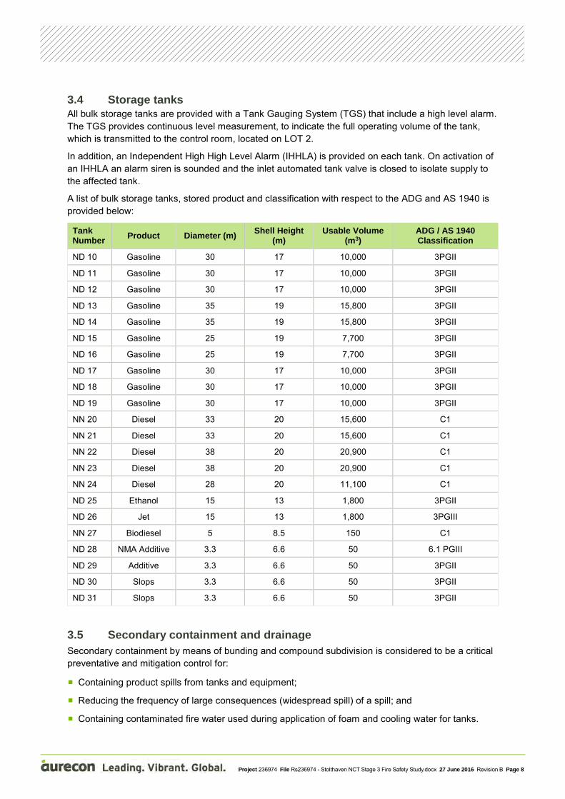
3.4 Storage tanks All bulk storage tanks are provided with a Tank Gauging System (TGS) that include a high level alarm. The TGS provides continuous level measurement, to indicate the full operating volume of the tank, which is transmitted to the control room, located on LOT 2.
In addition, an Independent High High Level Alarm (IHHLA) is provided on each tank. On activation of an IHHLA an alarm siren is sounded and the inlet automated tank valve is closed to isolate supply to the affected tank.
A list of bulk storage tanks, stored product and classification with respect to the ADG and AS 1940 is provided below:
Tank Number Product Diameter (m) Shell Height
(m) Usable Volume
(m3) ADG / AS 1940 Classification
ND 10 Gasoline 30 17 10,000 3PGII
ND 11 Gasoline 30 17 10,000 3PGII
ND 12 Gasoline 30 17 10,000 3PGII
ND 13 Gasoline 35 19 15,800 3PGII
ND 14 Gasoline 35 19 15,800 3PGII
ND 15 Gasoline 25 19 7,700 3PGII
ND 16 Gasoline 25 19 7,700 3PGII
ND 17 Gasoline 30 17 10,000 3PGII
ND 18 Gasoline 30 17 10,000 3PGII
ND 19 Gasoline 30 17 10,000 3PGII
NN 20 Diesel 33 20 15,600 C1
NN 21 Diesel 33 20 15,600 C1
NN 22 Diesel 38 20 20,900 C1
NN 23 Diesel 38 20 20,900 C1
NN 24 Diesel 28 20 11,100 C1
ND 25 Ethanol 15 13 1,800 3PGII
ND 26 Jet 15 13 1,800 3PGIII
NN 27 Biodiesel 5 8.5 150 C1
ND 28 NMA Additive 3.3 6.6 50 6.1 PGIII
ND 29 Additive 3.3 6.6 50 3PGII
ND 30 Slops 3.3 6.6 50 3PGII
ND 31 Slops 3.3 6.6 50 3PGII
3.5 Secondary containment and drainage Secondary containment by means of bunding and compound subdivision is considered to be a critical preventative and mitigation control for:
Containing product spills from tanks and equipment;
Reducing the frequency of large consequences (widespread spill) of a spill; and
Containing contaminated fire water used during application of foam and cooling water for tanks.

Project 236974 File Rs236974 - Stolthaven NCT Stage 3 Fire Safety Study.docx 27 June 2016 Revision B Page 9
The effectiveness of the secondary containment system depends on the size and the construction of the bunds, and the efficiency of the drainage system.
Table 2 Bund capacity summary
Compound Largest Tank Gross Capacity (m3) Capacity of bund (m3) Ratio of capacity to
largest tank volume
1 – Flammable Liquids 12,064 14,267 118%
2 – Flammable Liquids 18,335 21,349 116%
3 – Flammable Liquids 12,064 14,300 118%
4 – Combustible Liquids 22,778 26,360 116%
5- Flammable Liquids 167 195 117% The bunds have been designed to contain spills and temporarily contain storm water prior to discharge into an oily water separator unit. There is one large oily water treatment unit to cater for the Stage 3 terminal.
In accordance with AS 1940 the net capacity of the compound is required to be at least the capacity of the largest tank plus the output of any fire water over a 20 minute period.
AS 1940 recommends that the bund volumes are sized and designed to minimise the area of fuel burning in the event of a bund fire scenario. This has been achieved by the provision of intermediate bund walls.
All compound drainage is by pumpout (over the bund wall) rather than by gravity drainage. This is a passive design feature which will prevent inadvertent release due to failure to close bund valves.
3.6 Slops Slops will be generated onsite from the following sources:
Bulk tank dewatering operations
Tanker truck drain-down
Each bulk tank, that requires regular dewatering, will have an associated tundish used for dewatering. Product is drawn from the heel of the tank and allowed to settle in the tundish. Any water in the tundish will be pumped to the slops tanks, including any water/product interface and the remaining product will be pumped back to the bulk tank.
Prior to tanker loading, any remaining product in the tanker is drained and pumped into the slops tanks. Each drain down is approximately 10 L per tanker compartment. This product could be flammable or combustible.
The Stolthaven site will not treat or reuse any slops generated. Once the slops tank is approaching full it will be loaded into a waste oil vessel and transported off site for processing by a third party.

Project 236974 File Rs236974 - Stolthaven NCT Stage 3 Fire Safety Study.docx 27 June 2016 Revision B Page 1
3.7 Emergency Shut Down The new site will incorporate a site wide ESD system. ESD push buttons will be strategically placed around the site and will, as a minimum, be located in the following locations:
In each road tanker gantry bay
At pump rafts
At inlet manifolds
At the Vapour Recovery Unit
At the Switchrooms
On activation of an ESD the following functions will be performed:
All product pumps shut down
All automated tank valves close
Air supply to all drainage, slops and dewatering pumps isolated.
ESD siren
SMS automatically sent to site manager’s phone
3.8 Fire Alarms The Stage 3 terminal will be provided with a fire alarm system. Manual fire alarm call points (MCP) will be positioned at strategic locations. If activated, these send a signal back to the fire indication panel (FIP) in the main terminal control room, located on LOT 2.
The FIP is equipped to contact the Fire and Rescue New South Wales (FRNSW) alerting an alarm condition. The FIP and/or MCPs do not activate the fire water pumps.
Evacuation of all non-essential personnel and all vehicles will occur on sounding of the fire alarm.
All fire alarms initiate the following actions:
Sound the site fire alarm siren and transmit a signal to FRNSW;
Open the main site access gates; and
Activates the emergency shut-down system.
The fire alarm system will be designed and installed in accordance with the relevant sections of AS 1940 and AS 1670.

Project 236974 File Rs236974 - Stolthaven NCT Stage 3 Fire Safety Study.docx 27 June 2016 Revision B Page 2
4 Hazard Identification The following potentially hazardous scenarios were identified:
Major mechanical failure of a tank resulting in a major loss of containment;
Tank roof failure for fixed cone roof tanks;
Pipe failure (piping within the Terminal) resulting in a loss of containment scenario;
Spills of flammable or combustible liquids into the bunds (i.e. tank overfill, incorrect maintenance, etc.);
Leaks during filling of road tanker or road tanker drive-away incident (i.e. driver does not disconnect the hose and drives away from the loading bay);
Leak at product pumps;
Natural phenomenon: Strong winds, bush fires, earthquakes, lightning strikes; and
Breach of security / sabotage.
A HAZOP was conducted by others, and is included in Appendix B.
4.1 Hazardous Materials The following hazardous materials shall be stored onsite:
Biodiesel;
Diesel;
Ethanol;
Gasoline: ULP (Unleaded Petrol) and PULP (Premium Unleaded Petrol);
Jet Fuel;
SLOPS; and
Additives
For the purpose of modelling completed as part of the FSS, Additives and SLOPS were assumed to have the same properties as Gasoline, and Biodiesel was assumed to have the same properties as Diesel.
A list of hazardous materials identified and their respective properties is presented in Table 3.
Table 3 Materials Properties
Product ADG / AS 1940 Classification
UN No. and HAZCHEM Code
Flash Point (°C)
Flammability limits in air (%)
Diesel C1 UN3082 (3Z) 61 NA
Gasoline 3 PG II 1203 (3YE) -40 1.4 – 7.6
Ethanol 3 PG II 1170 (2YE) 13 3.5 - 19
Jet 3 PG III 1863 3YE 38 0.7 – 6.0
Gasoline Additive 3 PG III UN1993 44 Not Determined
Diesel Additive 3 PG III UN1993 56 Not Determined
N-Methyl Aniline 6.1 PG III UN2294 (3X) 78 NA

Project 236974 File Rs236974 - Stolthaven NCT Stage 3 Fire Safety Study.docx 27 June 2016 Revision B Page 3
4.2 Bulk storage tanks 4.2.1 Tank rupture A major mechanical failure of a bulk storage tank will result in a major loss of containment scenario. Such scenarios can rapidly escalate if an ignition source is found. Scenarios considered include:
Unignited product release (environmental consequences, not included in this FSS);
Immediate (direct) ignition of pool fire resulting in a pool fire within the compound; and / or
Delayed ignition resulting in a flash fire and / or an explosion.
4.2.2 Tank top pool fire Flammable liquid pool fires have a higher likelihood of occurrence than combustible liquid pool fires and the causes of such fires are well documented in the LASTFIRE project (Large Atmospheric Storage Tanks), Lees' Loss Prevention in the Process Industries: Hazard Identification, Assessment and Control, and work undertaken by others1.
Tank top pool fires include full surface fires and (rim) seal area fires. The design scenario depends on the tank construction: whether it is a fixed, cone roof tank or an external open top floating roof tank, and also considers the provision or otherwise of an internal floating blanket: whether these are aluminium pontoon type or full metal contact as per API 650 and NFPA 11 requirements.
Design Scenarios involving tank top pool fires are identified in Section 5.1.
4.2.3 Flash fire or explosion Flash fires or explosion scenarios may occur as a result of a major loss of containment scenario: tank ruptures, overfilling or pipework failures are the common causes of loss of containment.
A Vapour Cloud Explosion (VCE) is associated with the release of chemical and physical energy. The following parameters significantly influence the likelihood of, and the overpressures generated by a VCE:
Flammability and quantity of fuel;
Degree of confinement/congestion;
Source and strength of ignition; and
Weather conditions.
A VCE typically results in extensive equipment damage and injury/fatality across a large area, depending on the level of confinement and size of the vapour cloud.
A flash fire scenario is likely to result in fatality within the flash fire envelope with limited damage to plant. Typically, the burning zone is estimated by first performing a dispersion model and defining the burning zone from the LFL back to the release point..
1 Tank Fires - Review of fire incidents 1951–2003. BRANDFORSK Project 513-021. SP Swedish National Testing and Research Institute (2004)

Project 236974 File Rs236974 - Stolthaven NCT Stage 3 Fire Safety Study.docx 27 June 2016 Revision B Page 4
4.2.4 Vent fire Flammable vapour being vented may be ignited resulting in a vent fire. Tank vent fires are more likely to occur than full surface tank fires, however the effects are usually minimal. When addressed, vent fires can usually be extinguished with minimal damage and low risk to personnel using first aid measures such as fire extinguishers or hose streams.
In addition, the likelihood of escalation of a vent fire is low as the vapour space is typically either too rich (PV vented tanks) or too lean (tanks open to atmosphere) to support combustion.
4.2.5 Bund fire A bund fire may occur as a result of a major loss of containment scenario: tank ruptures, overfilling or pipework failures are the common causes of loss of containment. The size of the fire depends on the amount of product spilt and ranges from an intermediate bunded area pool fire to a full bunded area pool fire. Reviewing the provision and integrity of intermediate bunds is one means of minimising the size of a pool fire.
4.3 Road tanker loading operations 4.3.1 Gantry pool fire A gantry pool fire may occur where flammable or combustible liquids are handled.
The loading gantry will handle flammable liquids, a pool fire in a single bay has been considered to be a Design Scenario. Note that the impact from a pool fire in a single bay may impact on equipment and / or personnel in adjacent bays. A drainage system provides gravity drainage away from the gantry to a remote impounding basin (which has foam application). Flash fire or explosion
As displaced vapours from loading operations are processed in a Vapour Recovery Unit (VRU), flash fires and or explosion scenarios are not considered.
A major loss of containment scenario followed by delayed ignition may result in an explosion or a flash fire scenario. As the loading gantries are provided with a drainage system that acts to remove spilt product away from the loading area thereby minimising the amount of product that can disperse, it is considered that a dispersing cloud is not likely to hold sufficient flammable mater to cause significant overpressure in the event of an explosion. The worst case event may be a limited extent flash fire.
4.4 Pipework and pipelines 4.4.1 Leak A jet fire occurs when a high velocity discharge (release from a pipeline or pipework) ignites. The flame produces varying amounts of smoke depending on the material released and the degree of air entrainment during the discharge.
By their nature, jet fires are very hot and erosive and have the potential to rapidly weaken exposed plant and equipment, even in instances where passive fire protection is provided. They also pose a serious thermal risk to personnel. The potential heat flux in the flame of a jet fire can be in the order of 350 kW/m2.
Escalation from a jet fire scenario would normally involve direct flame impingement or prolonged exposure to high heat radiation exposure.
4.4.2 Rupture A rupture of a pipeline or pipework will result in a loss of containment of product, which if ignited will result in a pool fire. Depending on the nature of the topography (typically pipelines) and potential containment options the pool fire will either be unconfined (or broadly confined to the general topography) or confined in the bunded area.
Project 236974 File Rs236974 - Stolthaven NCT Stage 3 Fire Safety Study.docx 27 June 2016 Revision B Page 5
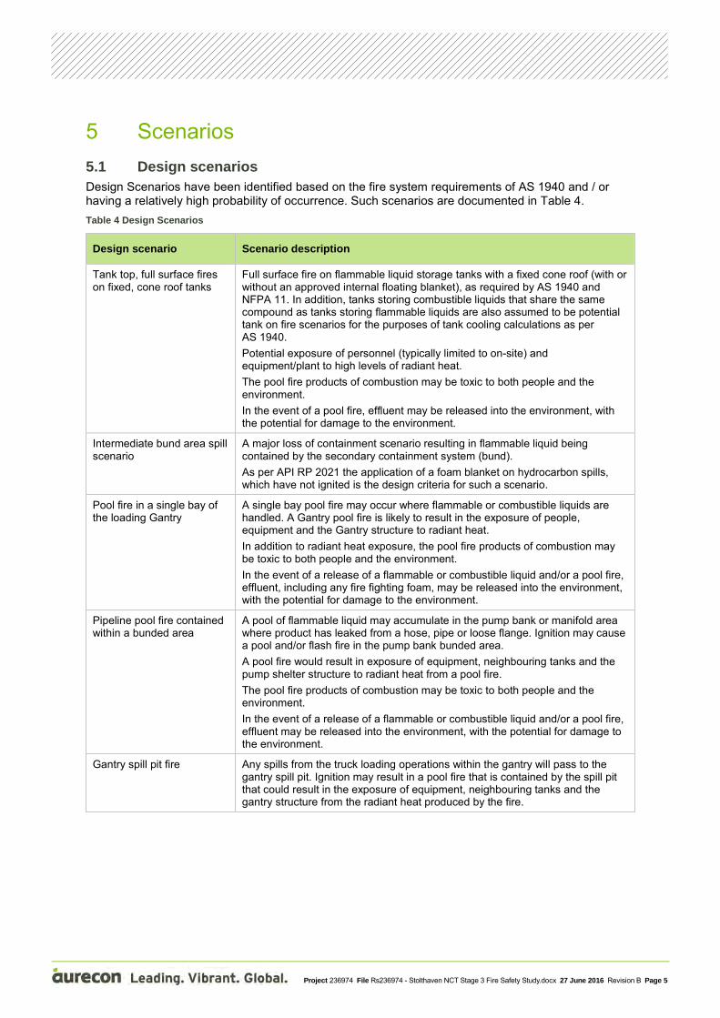
5 Scenarios 5.1 Design scenarios Design Scenarios have been identified based on the fire system requirements of AS 1940 and / or having a relatively high probability of occurrence. Such scenarios are documented in Table 4. Table 4 Design Scenarios
Design scenario Scenario description
Tank top, full surface fires on fixed, cone roof tanks
Full surface fire on flammable liquid storage tanks with a fixed cone roof (with or without an approved internal floating blanket), as required by AS 1940 and NFPA 11. In addition, tanks storing combustible liquids that share the same compound as tanks storing flammable liquids are also assumed to be potential tank on fire scenarios for the purposes of tank cooling calculations as per AS 1940. Potential exposure of personnel (typically limited to on-site) and equipment/plant to high levels of radiant heat. The pool fire products of combustion may be toxic to both people and the environment. In the event of a pool fire, effluent may be released into the environment, with the potential for damage to the environment.
Intermediate bund area spill scenario
A major loss of containment scenario resulting in flammable liquid being contained by the secondary containment system (bund). As per API RP 2021 the application of a foam blanket on hydrocarbon spills, which have not ignited is the design criteria for such a scenario.
Pool fire in a single bay of the loading Gantry
A single bay pool fire may occur where flammable or combustible liquids are handled. A Gantry pool fire is likely to result in the exposure of people, equipment and the Gantry structure to radiant heat. In addition to radiant heat exposure, the pool fire products of combustion may be toxic to both people and the environment. In the event of a release of a flammable or combustible liquid and/or a pool fire, effluent, including any fire fighting foam, may be released into the environment, with the potential for damage to the environment.
Pipeline pool fire contained within a bunded area
A pool of flammable liquid may accumulate in the pump bank or manifold area where product has leaked from a hose, pipe or loose flange. Ignition may cause a pool and/or flash fire in the pump bank bunded area. A pool fire would result in exposure of equipment, neighbouring tanks and the pump shelter structure to radiant heat from a pool fire. The pool fire products of combustion may be toxic to both people and the environment. In the event of a release of a flammable or combustible liquid and/or a pool fire, effluent may be released into the environment, with the potential for damage to the environment.
Gantry spill pit fire Any spills from the truck loading operations within the gantry will pass to the gantry spill pit. Ignition may result in a pool fire that is contained by the spill pit that could result in the exposure of equipment, neighbouring tanks and the gantry structure from the radiant heat produced by the fire.
Project 236974 File Rs236974 - Stolthaven NCT Stage 3 Fire Safety Study.docx 27 June 2016 Revision B Page 6
Design scenario Scenario description
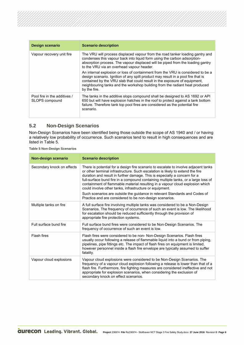
Vapour recovery unit fire The VRU will process displaced vapour from the road tanker loading gantry and condenses this vapour back into liquid form using the carbon adsorption-absorption process. The vapour displaced will be piped from the loading gantry to the VRU via an overhead vapour header. An internal explosion or loss of containment from the VRU is considered to be a design scenario. Ignition of any spilt product may result in a pool fire that is contained by the VRU slab that could result in the exposure of equipment, neighbouring tanks and the workshop building from the radiant heat produced by the fire.
Pool fire in the additives / SLOPS compound
The tanks in the additive slops compound shall be designed to AS 1692 or API 650 but will have explosion hatches in the roof to protect against a tank bottom failure. Therefore tank top pool fires are considered as the potential fire scenario.
5.2 Non-Design Scenarios Non-Design Scenarios have been identified being those outside the scope of AS 1940 and / or having a relatively low probability of occurrence. Such scenarios tend to result in high consequences and are listed in Table 5. Table 5 Non-Design Scenarios
Non-design scenario Scenario description
Secondary knock on effects There is potential for a design fire scenario to escalate to involve adjacent tanks or other terminal infrastructure. Such escalation is likely to extend the fire duration and result in further damage. This is especially a concern for a full-surface bund fire in a compound containing multiple tanks, or a large loss of containment of flammable material resulting in a vapour cloud explosion which could involve other tanks, infrastructure or equipment. Such scenarios are outside the guidance in relevant Standards and Codes of Practice and are considered to be non-design scenarios.
Multiple tanks on fire A full surface fire involving multiple tanks was considered to be a Non-Design Scenarios. The frequency of occurrence of such an event is low. The likelihood for escalation should be reduced sufficiently through the provision of appropriate fire protection systems.
Full surface bund fire Full surface bund fires were considered to be Non-Design Scenarios. The frequency of occurrence of such an event is low.
Flash fires Flash fires were considered to be non- Non-Design Scenarios. Flash fires usually occur following a release of flammable liquid into a bund or from piping, pipelines, pipe fittings etc. The impact of flash fires on equipment is limited, however personnel inside a flash fire envelope are typically assumed to suffer fatality.
Vapour cloud explosions Vapour cloud explosions were considered to be Non-Design Scenarios. The frequency of a vapour cloud explosion following a release is lower than that of a flash fire. Furthermore, fire fighting measures are considered ineffective and not appropriate for explosion scenarios, when considering the exclusion of secondary knock on effect scenarios.

Project 236974 File Rs236974 - Stolthaven NCT Stage 3 Fire Safety Study.docx 27 June 2016 Revision B Page 7
Non-design scenario Scenario description
Pipeline jet fire Jet fires could occur during the pumping of flammable liquids within the Terminal. In accordance with CPR 18E, a leak is defined as the outflow with an effective diameter of 10% of the nominal diameter, up to a maximum of 50 mm. In the event of a loss of containment scenario from a pipeline or pipework within the terminal, as a result of a leak, and ignition the jet fire may result in exposure to people, equipment and other structures. Although the frequency of a jet fire from pressurised pipelines or piping is relatively high following a highly pressurised release of flammable liquid, the likelihood of a highly pressurised release is relatively low.
Non-Design scenarios (larger, very low likelihood scenarios) are not usually required to be provided with fixed fire systems and are typically managed through effective emergency response planning and mutual aid arrangements. Exceptions may be made to this on a risk basis where the potential consequences associated with the scenario are unacceptable (for example, for operations that are close to residential areas or other sensitive developments such as hospitals or schools).
Risk reduction is a core component of both design and non-design scenarios and is typically achieved as follows:
Identification of layers of protection or preventative measures to reduce the likelihood of occurrence;
Implementation of fire safety management systems such as the development of pre-fire plans and emergency response plans;
Development of “mutual aid” strategies;
Reliance on the emergency services – particularly the Local Fire Brigade; and
Providing effective means of access and egress from affected areas.

Project 236974 File Rs236974 - Stolthaven NCT Stage 3 Fire Safety Study.docx 27 June 2016 Revision B Page 8
6 Consequence Effects Analysis Tank Top Fires Heat Radiation Modelling Report No: 11039 Rev B.
6.1 Heat radiation contours The heat radiation contours are reproduced from the Tank Top Fires Heat Radiation Modelling (Report No: 11039 Rev B) IN Table 6. The heat radiation contours are calculated at a height above ground of 2 m and are measured from the centre of the tank on fire.
Table 6 Heat radiation contours
Tank on Fire Product
Heat radiation contour distances from centre of tank on fire (m)
4.7 kW/m2 8.0 kW/ m2 12.6 kW/ m2
ND 10 Gasoline 36 level not reached level not reached
ND 11 Gasoline 36 level not reached level not reached
ND 12 Gasoline 36 level not reached level not reached
ND 13 Gasoline 42 level not reached level not reached
ND 14 Gasoline 44 level not reached level not reached
ND 15 Gasoline 29 level not reached level not reached
ND 16 Gasoline 29 level not reached level not reached
ND 17 Gasoline 36 level not reached level not reached
ND 18 Gasoline 36 level not reached level not reached
ND 19 Gasoline 36 level not reached level not reached
ND 20 Diesel 38 level not reached level not reached
NN 21 Diesel 38 level not reached level not reached
NN 22 Diesel 45 level not reached level not reached
NN 23 Diesel 45 level not reached level not reached
NN 24 Diesel 29 level not reached level not reached
ND 25 Ethanol level not reached level not reached level not reached
ND 26 Jet 19 level not reached level not reached
6.2 Dispersion modelling Release of liquid petrol to the bunded areas results in evaporation and the generation of a vapour cloud. Depending on the atmospheric conditions – wind speed and temperature affecting evaporation, and atmospheric stability and wind speed affecting dispersion – a flammable vapour cloud can form. Under unstable atmospheric stability conditions, a flammable vapour cloud is not predicted to occur, Under low wind speed conditions at night with stable or very stable atmospheric wind conditions (Pasquill classes E and F) a dense flammable vapour cloud can form and disperse long distances downwind.
EFFECTS® consequence modelling software was used to determine the flammable vapour cloud concentration as a function of distance. Concentrations between the Lower Explosion Limit (LEL) and Upper Explosion Limit (UEL) of flammable material / air mixture were determined to estimate the explosive mass in the vapour cloud.

Project 236974 File Rs236974 - Stolthaven NCT Stage 3 Fire Safety Study.docx 27 June 2016 Revision B Page 9
The results from the dispersion modelling are presented in Table 7, in terms of the flammable cloud area at ground level and explosive mass.
Table 7 Dispersion modelling – Flammable vapour cloud volume
Scenario modelled Flammable cloud area (m2) Flammable cloud explosive mass (kg)
Full Bund Spill – Compound 1- Petrol Bund 44,073 3,145
Full Bund Spill – Compound 2 - Petrol Bund 63,571 4,823
Full Bund Spill – Compound 3 - Petrol Bund 47,384 3,388
Tank Overflow – Compound 1 - Petrol Bund 23,514 1,462
Tank Overflow – - Compound 2 Petrol Bund 25,962 1,615
Tank Overflow – Compound 2 Petrol Bund 25,962 1,615
6.2.1 Explosion analysis Release of liquid petrol to the bunded areas results in evaporation and the generation of a vapour cloud. Depending on the atmospheric conditions -wind speed and temperature affecting evaporation, and atmospheric stability and wind speed affecting dispersion – a flammable vapour cloud can form.
Particularly under low wind speed, very stable atmospheric stability conditions, a flammable vapour clouds can form and travel a considerable distance from the point of release. The area for evaporation is an important parameter in determining the evaporation rate and hence the size of the resulting flammable cloud.
The Terminal QRA considered a number of initiating events that could result in loss of liquid containment. These include tank top overflow and tank failures leading to either gradual or catastrophic loss of tank contents. For the QRA, each of these events was calculated for each tank and for all combinations of wind speed, direction and atmospheric stability class.
Presented below are the results of modelling both a full bund spill (catastrophic failure) and tank overflow scenarios, with a wind speed of 1.9 m/s and Pasquill atmospheric stability class F (very stable) using EFFECTS® consequence modelling software. It should be noted that all modelling uses a multicomponent representation for petrol, and the results are similar to using n-pentane as a “representative” chemical.
The extent of the flammable vapour cloud assumes that ignition will occur 3 minutes after the liquid pool forms. At this point, the vapour cloud is well beyond the terminal site and ignition sources are uncontrolled.
The results from the explosion analysis are presented in Table 8 for wind speed/stability pair of F1.9.
Table 8 Explosion modelling – Overpressure Contours
Scenario modelled Overpressure level and distance (m) to overpressure level (from the centre of the modelled scenario)
7 kPa 14 kPa 21 kPa 35 kPa
Full Bund Spill – Compound 1 -Petrol Bund 264 184 157 135
Full Bund Spill – Compound 2 -Petrol Bund 303 211 180 154
Full Bund Spill – Compound 3 - Petrol Bund 272 190 163 139
Tank Overflow – Compound 1 - Petrol Bund 208 146 125 108

Project 236974 File Rs236974 - Stolthaven NCT Stage 3 Fire Safety Study.docx 27 June 2016 Revision B Page 10
Scenario modelled Overpressure level and distance (m) to overpressure level (from the centre of the modelled scenario)
7 kPa 14 kPa 21 kPa 35 kPa
Tank Overflow – Compound 2 - Petrol Bund 215 151 130 112
Tank Overflow – Compound 3 - Petrol Bund 215 151 130 112
is a graphical presentation of the extent of the flammable vapour cloud for a full bund spill to the Mid Petrol Bund (Compound 2) with a westerly wind at 1.9m/s under very stable atmospheric conditions. The blue contour represents the extent of the flammable cloud at 180s. The dashed blue circle is a surrounding contour to visualise the extent of the flammable cloud for other wind directions.
The green circle is the 7kPa overpressure contour. The dashed green circle is a surrounding contour to visualise the extent of the overpressure limit of 7kPa for other wind directions.
The tan circle is the 14kPa overpressure contour; the red circle the 21kPa contour; and the magenta circle is the 100kPa contour.
Figure 2 Flammable Vapour Cloud and Incident Overpressure Contours – Image Courtesy of Cockshott Consulting
Pty Ltd

Project 236974 File Rs236974 - Stolthaven NCT Stage 3 Fire Safety Study.docx 27 June 2016 Revision B Page 11
6.2.2 Bund flash fire scenarios The modelling described above defines the extent of the flammable vapour cloud for the specified conditions. If a flash fire occurs, any person in the open within the extent of the blue contour in would receive fatal burns.
Aurecon note that a catastrophic tank rupture is a very low likelihood event. As such no fixed infrastructure is required to mitigate such a scenario and preventative control measures are more appropriate.
Project 236974 File Rs236974 - Stolthaven NCT Stage 3 Fire Safety Study.docx 27 June 2016 Revision B Page 12
7 Risk reduction measures This Section summarise the proposed risk reduction measures associated with the Stage 3 works in line with “best practice” terminal operation. The provision of risk reduction measures are critical to the safe operation of the Terminal and reduce the likelihood of high consequence events (major accident hazards) occurring. The following risk reduction measures have been identified:
7.1 General 7.1.1 Entry controls Full site perimeter fencing with automatic gates prevents unauthorised access to the site.
7.1.2 Control of ignition sources Sources of ignition will be controlled in areas where the potential exists for the presence of flammable vapour-air mixtures. Typical ignition sources include, but are not limited to: lightning, static electricity, stray currents, hot work, internal combustion engines, smoking, and improperly classified or unprotected electrical equipment. AS 60079 (series) specifies the general requirements for construction, testing and marking of electrical equipment and Ex Components intended for use in explosive atmospheres.
Management of work in hazardous areas is achieved through the use of hot work permits.
7.1.3 Tank separation distances Tank to tank and tank to Terminal infrastructure is considered to be a layer of protection in that the likelihood of escalation or fire damage to equipment, and important buildings is reduced as the separation distance increases. Tank separation distances have been set to meet the minimum requirements of AS 1940.
7.1.4 Emergency shut down and isolation Provision for emergency shutdown and isolation of equipment minimises the likelihood or consequences of a loss of containment scenario. Emergency shut down systems are provided at the road loading gantries, pump bays and inlet manifold areas
7.1.5 Emergency planning and Training A written emergency action plan that is consistent with available equipment and personnel will be established to respond to fires and related emergencies. This plan will include the following information (as a minimum):
Procedures to be followed in case of fire or release of liquids or vapours, such as sounding the alarm, notifying the fire department, evacuating personnel, and controlling and extinguishing the fire;
Procedures and schedules for conducting drills of these procedures;
Appointment and training of personnel to carry out assigned duties, including review at the time of initial assignment, as responsibilities or response actions change, and whenever anticipated duties change;
Procedures for maintenance and operation of:
− Fire protection equipment and systems;
− Drainage and containment systems; and
− Dispersion and ventilation equipment and systems.

Project 236974 File Rs236974 - Stolthaven NCT Stage 3 Fire Safety Study.docx 27 June 2016 Revision B Page 13
Procedures for shutting down or isolating equipment to reduce, mitigate, or stop the release of liquid or vapours, including assigning personnel responsible for maintaining critical plant functions or shutdown of plant processes and safe start-up following isolation or shutdown; and
Alternate measures for the safety of occupants.
Personnel responsible for the use and operation of fire protection equipment will be trained in the use of that equipment. Refresher training will be conducted at least annually.
7.1.6 Maintenance and Inspection Maintaining the integrity of the bulk storage tanks, piping and other related infrastructure required for the safe operation of the terminal is essential in reducing the risk associated with product spills, fires and explosions. A comprehensive maintenance and inspection plan will be developed to document the maintenance and inspection activities at a (minimum) frequency set by relevant Standards and Codes of Practice.
7.2 Bulk storage tanks 7.2.1 Overfill protection Tank overfill scenarios may result in a loss of containment that should be contained by the secondary containment system. In order to minimise loss of containment occurring due to overfilling a bulk storage tank, the storage tanks will be provided with an independent high high level alarm system. When a pre-determined level in the tank is reached, the independent high high level alarm will act to close the actuated tank inlet valve and sound an alarm on site and at the wharf. This system will act as an additional layer of protection in conjunction with the current tank gauging and monitoring system.
7.2.2 Tank construction Tank construction as a risk reduction measure depends on the physical and chemical properties of the particular product stored, and taking into consideration the operational preferences and meteorological conditions that the terminal is exposed to.
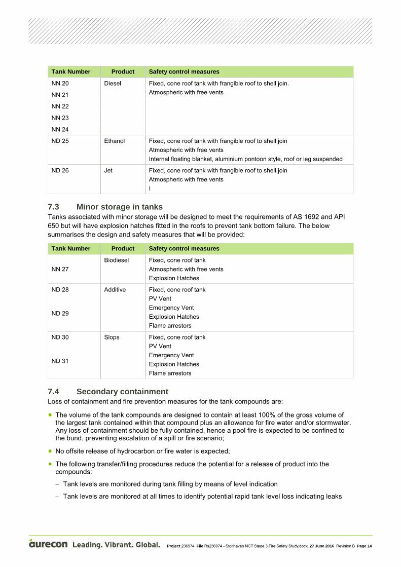
All bulk storage tanks will be designed to meet the requirements of API 650. The design and safety measures that will be provided as summarised below:
Tank Number Product Safety control measures
ND 10 Gasoline, various grades
Fixed, cone roof tank with frangible roof to shell join Atmospheric with free vents Internal floating blanket, aluminium pontoon style, roof or leg suspended
ND 11
ND 12
ND 13
ND 14
ND 15
ND 16
ND 17
ND 18
ND 19
Project 236974 File Rs236974 - Stolthaven NCT Stage 3 Fire Safety Study.docx 27 June 2016 Revision B Page 14
Tank Number Product Safety control measures
NN 20 Diesel Fixed, cone roof tank with frangible roof to shell join. Atmospheric with free vents NN 21
NN 22
NN 23
NN 24
ND 25 Ethanol Fixed, cone roof tank with frangible roof to shell join Atmospheric with free vents Internal floating blanket, aluminium pontoon style, roof or leg suspended
ND 26 Jet Fixed, cone roof tank with frangible roof to shell join Atmospheric with free vents I
7.3 Minor storage in tanks Tanks associated with minor storage will be designed to meet the requirements of AS 1692 and API 650 but will have explosion hatches fitted in the roofs to prevent tank bottom failure. The below summarises the design and safety measures that will be provided:
Tank Number Product Safety control measures
NN 27 Biodiesel Fixed, cone roof tank
Atmospheric with free vents Explosion Hatches
ND 28 Additive Fixed, cone roof tank PV Vent Emergency Vent Explosion Hatches Flame arrestors
ND 29
ND 30 Slops Fixed, cone roof tank PV Vent Emergency Vent Explosion Hatches Flame arrestors
ND 31
7.4 Secondary containment Loss of containment and fire prevention measures for the tank compounds are:
The volume of the tank compounds are designed to contain at least 100% of the gross volume of the largest tank contained within that compound plus an allowance for fire water and/or stormwater. Any loss of containment should be fully contained, hence a pool fire is expected to be confined to the bund, preventing escalation of a spill or fire scenario;
No offsite release of hydrocarbon or fire water is expected;
The following transfer/filling procedures reduce the potential for a release of product into the compounds:
− Tank levels are monitored during tank filling by means of level indication
− Tank levels are monitored at all times to identify potential rapid tank level loss indicating leaks

Project 236974 File Rs236974 - Stolthaven NCT Stage 3 Fire Safety Study.docx 27 June 2016 Revision B Page 15
− Tanks are provided with high level alarms for alerting operators against overfilling a tank and automatically closing tank inlet
Regular testing and inspection of tanks reduces the potential for leaks into the compounds by identifying corrosion and other tank defects.
7.5 Product Inlet manifolds Risk reduction measures for the product inlet manifold are as follows:
The manifold is located within a dedicated containment area, hence retaining spilled hydrocarbon and reducing the potential for spreading and escalation of a potential pool fire;
7.6 Pump bank and product transfer pumps Risk reduction measures for the pump bank areas are as follows:
Piping between tanks and pumps is generally located in the main tank compound so that any loss of containment should be retained within the main bunded area;
The product pumps are located within a dedicated containment area with the release of product expected to be retained within these areas. The extent of any pool fire should be limited to the containment area, preventing a spreading pool fire or escalation of a pool fire;
The number of flanges on the pipework that is not located in a spill containment area is minimised to reduce the potential for loss of containment;
7.7 Gantry operations Risk reduction measures for Gantry operations are as follows:
The gantry operations require the all road tankers comply with the Safe Load Program (SLP) for the safe loading at terminals and depots. Non-compliance to SLP Pass-2-Load may prevent the vehicle from loading.
The loading bay area is bunded to minimise the spread of any spills and drains are provided that pass directly to a remote impounding basin;
Tanker unloading operations are monitored by drivers during transfers so the source and extent of a release should be rapidly identified. The loading gantry is under CCTV surveillance at all times – monitored at the site office.
Tanker loading operations are monitored by the driver and have an automated “traffic light” system in each gantry bay, so the likelihood of a drive-away incident is low;
Dry break couplings are provided on loading arms, this minimises the quantity of product that could be released during a drive-away incident.
A driver “deadman” system is operated in each loading bay. This requires regular acknowledgment by the driver during filling. If this is not acknowledged then the loading in that bay will automatically shut down.
Each loading gantry is connected to a VRU via fully enclosed piping to process displaced vapours from tanker trucks;
Transfer systems are computer controlled. This reduces the potential for a release.
Gantry areas are open so natural ventilation occurs, displacing vapours from tanker truck venting during loading/unloading;
Bollard and ‘Armco’ protection is provided On entry to the gantry to minimise collision with other tankers and equipment that could result in a possible loss of containment
Project 236974 File Rs236974 - Stolthaven NCT Stage 3 Fire Safety Study.docx 27 June 2016 Revision B Page 16
8 Fire Protection Systems The fire protection systems at the Terminal are expected to comprise:
Water supply from Town water mains and storage in fixed water storage tanks;
Water distribution system comprising of a hydrant ring main;
Bulk storage tank foam systems:
Gantry fixed foam systems;
Other (miscellaneous) fire protection systems; and
Protection for Non-Design Scenarios.
Drawings of the proposed fire protection systems at the Terminal are included in Appendix A.
8.1 Water supply and storage The basis for the water supply and storage is AS 1940, which requires that sufficient fire water be available from static fire water storage tanks or mains or a combination of both to supply the sum of the requirements for at least 90 minutes of cooling water, the largest foam demand for a period no less than design and supplementary (hydrant) water for at least 240 minutes.
8.1.1 Fire water storage tanks Water for fire fighting purposes will be stored in four 1.2 ML fire water storage tanks. Two are currently located as part of the existing terminal on LOT 2 and another two will be installed on LOT 36 as part of the Stage 3 works. The tanks will be connected and hydraulically balanced via a DN250 cross connection pipeline.
The fire water tanks will be connected to Town water mains to ensure that they are automatically filled and topped up following routing testing and maintenance activities.
8.1.2 Town water main system The fire water tanks are currently filled from the Town water mains.
The FSS notes that the on site storage capacity is sufficient to provide the maximum water for fire fighting purposes without the need for make up water from the Town water mains. Any additional water from the Town water mains will provide additional duration (time) for fire fighting purposes.
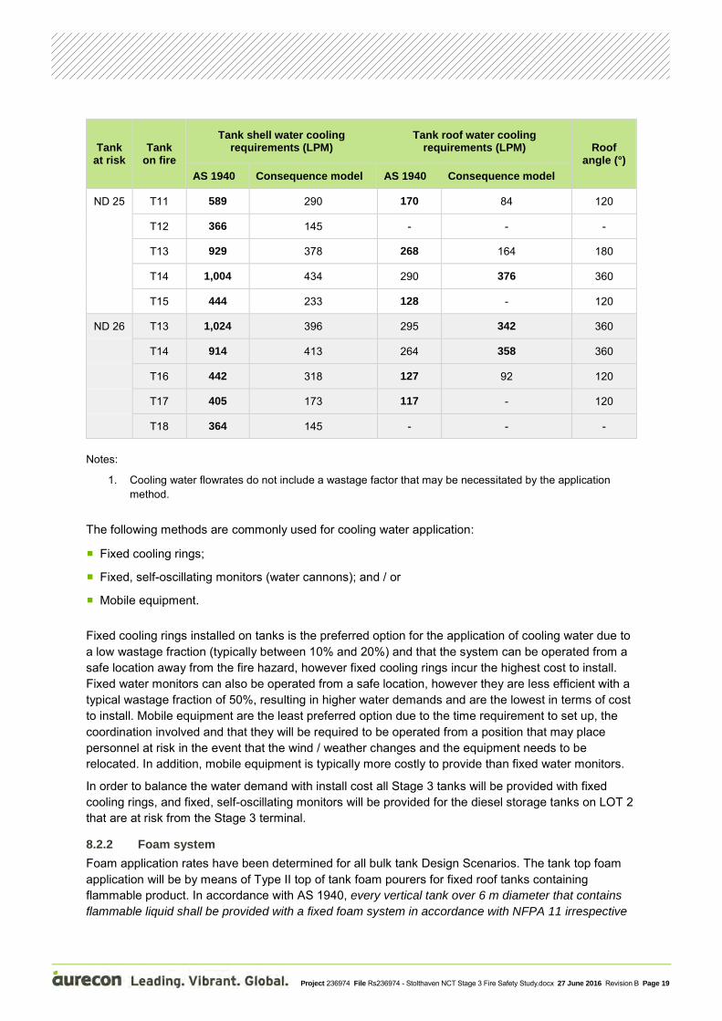
8.2 Bulk storage tanks 8.2.1 Cooling water system The tank cooling water requirements were calculated in accordance with AS 1940 Appendix J for Design Scenarios identified in Section 5.1. In addition, consequence effects modelling was conducted to determine the cooling water required for each Design Scenario (refer Section 6).
The AS 1940 Appendix J calculations assume that the exposed area of the tank is a 120° sector facing the potential tank on fire. Where neighbouring tanks are within 1.5 times the diameter of a potential tank on fire, it is considered that the tank shell will require cooling water application. Where neighbouring tanks are within 1.0 times the diameter of a potential tank on fire, it is considered that the tank roof will require cooling water application. The cooling water application rates are based on the tank separation distance and the diameter of the tank on fire and is represented in Figure J1.
In accordance with the EI MCSP Part 19, where adjacent tank exposure levels are likely to be greater than 8 kW/m2, as determined by consequence effects analysis, cooling water should be applied. For

Project 236974 File Rs236974 - Stolthaven NCT Stage 3 Fire Safety Study.docx 27 June 2016 Revision B Page 17
the tank shell, a 120° sector is assumed for the neighbouring tank that faces a potential tank on fire, similar to the AS 1940 calculation. For the tank roof, the area of the roof is estimated from the consequence effects analysis and either a 120°, 180° or 360° roof sector is used as the area requiring cooling water application.
The tank cooling flowrates are presented in Table 9.
Table 9 Tank shell and roof cooling requirements from AS 1940 and consequence modelling
Tank at risk
Tank on fire
Tank shell water cooling requirements (LPM)
Tank roof water cooling requirements (LPM) Roof
angle (°) AS 1940 Consequence model AS 1940 Consequence model
ND 1 T12 1,039 363 - - -
ND 2 T11 1,105 419 - - -
T12 1,379 669 738 - 120
ND 3 T10 1,172 476 - - -
T11 1,327 623 710 - 120
ND 5 T10 1,249 544 - - -
ND 10 T11 2,265 1,386 999 611 120
T15 1,205 804 532 354 120
ND 11 T10 2,265 1,386 999 611 120
T12 2,265 1,386 999 611 120
T13 692 - - - -
T14 884 305 - - -
T15 859 406 - - -
T25 694 74 - - -
ND 12 T11 2,265 1,386 999 611 120
T14 1,980 1,228 874 542 120
ND 13 T14 1,973 1,241 909 571 120
T15 2,372 1,481 1,092 682 120
T17 1,934 1,301 891 598 120
T18 846 205 - - -
T25 1,195 193 - - -
T26 1,316 2,842 - 1,308 120

Project 236974 File Rs236974 - Stolthaven NCT Stage 3 Fire Safety Study.docx 27 June 2016 Revision B Page 18
Tank at risk
Tank on fire
Tank shell water cooling requirements (LPM)
Tank roof water cooling requirements (LPM) Roof
angle (°) AS 1940 Consequence model AS 1940 Consequence model
ND 14 T11 966 277 - - -
T12 2,162 1,445 996 666 120
T13 1,973 1,132 909 521 120
T16 2,366 2,180 1,089 1,506 180
T25 1,291 241 - - -
T26 1,176 2,493 - 1,147 120
ND 15 T10 1,385 886 455 291 120
T11 987 456 325 - 120
T13 2,482 1,325 816 654 180
T14 610 138 - - -
T25 600 69 - - -
ND 16 T13 613 146 - - -
T14 2,489 1,497 819 739 180
T18 1,081 559 355 - -
T19 1,204 697 396 229 120
T26 598 1,024 - 336 120
ND 17 T13 1,771 1,007 781 444 120
T18 2,265 1,386 999 611 120
ND 18 T13 775 - - - -
T14 672 - - - -
T16 941 767 - 338 120
T17 2,265 1,386 999 611 120
T19 2,265 1,386 999 611 120
ND 19 T16 1,048 924 462 407 120
T18 2,265 1,386 999 611 120
ND 20 T17 1,131 406 - - -
T18 1,520 801 627 - 120
ND 21 T18 1,133 406 - - -
T19 1,518 789 626 - 120
Project 236974 File Rs236974 - Stolthaven NCT Stage 3 Fire Safety Study.docx 27 June 2016 Revision B Page 19
Tank at risk
Tank on fire
Tank shell water cooling requirements (LPM)
Tank roof water cooling requirements (LPM) Roof
angle (°) AS 1940 Consequence model AS 1940 Consequence model
ND 25 T11 589 290 170 84 120
T12 366 145 - - -
T13 929 378 268 164 180
T14 1,004 434 290 376 360
T15 444 233 128 - 120
ND 26 T13 1,024 396 295 342 360
T14 914 413 264 358 360
T16 442 318 127 92 120
T17 405 173 117 - 120
T18 364 145 - - -
Notes:
1. Cooling water flowrates do not include a wastage factor that may be necessitated by the application method.
The following methods are commonly used for cooling water application:
Fixed cooling rings;
Fixed, self-oscillating monitors (water cannons); and / or
Mobile equipment.
Fixed cooling rings installed on tanks is the preferred option for the application of cooling water due to a low wastage fraction (typically between 10% and 20%) and that the system can be operated from a safe location away from the fire hazard, however fixed cooling rings incur the highest cost to install. Fixed water monitors can also be operated from a safe location, however they are less efficient with a typical wastage fraction of 50%, resulting in higher water demands and are the lowest in terms of cost to install. Mobile equipment are the least preferred option due to the time requirement to set up, the coordination involved and that they will be required to be operated from a position that may place personnel at risk in the event that the wind / weather changes and the equipment needs to be relocated. In addition, mobile equipment is typically more costly to provide than fixed water monitors.
In order to balance the water demand with install cost all Stage 3 tanks will be provided with fixed cooling rings, and fixed, self-oscillating monitors will be provided for the diesel storage tanks on LOT 2 that are at risk from the Stage 3 terminal.
8.2.2 Foam system Foam application rates have been determined for all bulk tank Design Scenarios. The tank top foam application will be by means of Type II top of tank foam pourers for fixed roof tanks containing flammable product. In accordance with AS 1940, every vertical tank over 6 m diameter that contains flammable liquid shall be provided with a fixed foam system in accordance with NFPA 11 irrespective

Project 236974 File Rs236974 - Stolthaven NCT Stage 3 Fire Safety Study.docx 27 June 2016 Revision B Page 20
of whether an internal or external roof is provided for the tank, unless the use of foam is inappropriate. Foam shall be applied as directly as possible to the liquid surface.
Application rates were calculated using the NFPA 11 application density of 4.1 LPM/m2 for fixed cone roof tanks and a foam concentrate ratio of 3%. The foam system requirements are presented in Table 10.
Table 10 Foam requirements based on NFPA 11
Tank Roof type Minimum discharge time (min)
Minimum discharge
outlets
Foam solution flowrate (LPM)
Foam concentrate flowrate (3%)
(LPM)
Foam concentrate storage (L)
ND 10 Fixed, Cone 55 2 2,898 87 4,782
ND 11 Fixed, Cone 55 2 2,898 87 4,782
ND 12 Fixed, Cone 55 2 2,898 87 4,782
ND 13 Fixed, Cone 55 2 3,945 118 6,509
ND 14 Fixed, Cone 55 2 3,945 118 6,509
ND 15 Fixed, Cone 55 2 2,013 60 3,321
ND 16 Fixed, Cone 55 2 2,013 60 3,321
ND 17 Fixed, Cone 55 2 2,898 87 4,782
ND 18 Fixed, Cone 55 2 2,898 87 4,782
ND 19 Fixed, Cone 55 2 2,898 87 4,782
ND 25 Fixed, Cone 55 1 725 22 1,195
ND 26 Fixed, Cone 30 1 725 22 652 Foam concentrate storage Foam concentrate is currently installed in a single 3,375 L foam bladder tank that provides foam to the diesel storage facility loading gantry. The FSS proposes that this system be dedicated to the diesel storage facility loading gantry and that a new foam concentrate storage system and proportioning system be provided for the Stage 3 works.
In accordance with NFPA 11, Clause 11.6.4 the foam concentration (in solution) is required to meet the following properties:
Not less than the rated concentration; and
No more than 30% above the rated concentrate, or 1 percentage point above the rated concentration (whichever is less).
As the foam concentrate storage presented in Table 10 are for 3% proportioned foam concentrate, the volumes should be considered as the minimum storage volumes. In practice, the actual achieved proportioning rate is likely to be around 3.3%, which will result in an increases the maximum storage requirement of 6,509 L to 7,160 L.
As the Stage 3 terminal will store ethanol, an alcohol resistant foam concentrate will be required.
Foam proportioning Foam proportioning involves the continuous introduction of foam concentrate at the design ratio into the water stream to form foam solution.
Project 236974 File Rs236974 - Stolthaven NCT Stage 3 Fire Safety Study.docx 27 June 2016 Revision B Page 21
The diesel terminal currently proportions foam via a bladder tank with a variable (range) proportioner (Angus BPP200 without improver). As the capacity of the bladder tank is significantly less than the required capacity, the FSS proposes that a new, centralised foam proportioning system be provided as part of the Stage 3 works.
The following methods are commonly used for foam proportioning:
Balanced pressure pump type proportioner;
Bladder tank with balanced pressure proportioner;
Inline eductor (inductor); and
Coupled water motor pump.
Balanced pressure pump type proportioner Pumped balanced pressure proportioning systems use foam concentrate pumps to pump foam concentrate, which is mixed into the water stream using a balanced pressure proportioner.
Pumped systems are typically used for foam application on multiple assets with differing demands. They have the highest initial and ongoing costs of the four commonly used options, but are considered to be the most versatile.
Bladder tank with balanced pressure proportioner Bladder tank systems utilise incoming water to pressurise a bladder containing foam concentrate. This pressurised foam concentrate is then mixed with water via a balanced pressure proportioner.
Sampling and testing the foam concentrate is difficult as these systems are inherently complex due to the number of control valves required. Bladder tank systems are typically installed for loading gantry fire protection.
Inline eductor (inductor) An inline eductor (inductor) is a fixed flow device which uses a venturi to create a pressure drop in order to draw in foam concentrate. It has a metering orifice in the foam concentrate line which ensures the correct mixing ratio.
Inductors operate based on a fixed flow creating a known pressure drop, therefore they are generally used for protection of a single fixed asset and can only operate under one design configuration.
Inductors typically require high inlet pressures (up to 10 bar) to operate correctly and have a typical pressure drop of 30-40% of the inlet pressure.
The main disadvantage of an inductor system is that they are susceptible to back pressure changes (deviations from design or as commissioned) and may not operate as intended should nozzles be blocked, or if a drain valve (or similar) downstream of the inductor is left open.
Coupled water motor pump The Knowsley SK Turbinator is a coupled water motor pump system which has recently been introduced to Terminals in Australia. It uses water flow to drive a positive displacement foam concentrate pump which pumps a corresponding amount of foam concentrate directly into the water stream to produce foam solution.
The Turbinator system operates similarly to balanced pressure type systems in that it has a low pressure loss and can proportion over a wide range of foam flowrates. Advantages over a balanced pressure proportioning system (bladder tank or pumped type) are significantly reduced cost, smaller footprint and lower complexity.
An alternative to the Turbinator system is the FireDos proportioning system. The advantages of the FireDos over the Turbinator are that it can be used for different foam concentrate proportioning rates:

Project 236974 File Rs236974 - Stolthaven NCT Stage 3 Fire Safety Study.docx 27 June 2016 Revision B Page 22
the Turbinator is set up for a single proportioning rate, it can also be used for 1% foam concentrate proportioning, whereas the Turbinator can only be used for 3% or 6% foam concentrate proportioning
Comparison Table 11 Comparison between proportioning devices
System Advantages Disadvantages
Balanced pressure pump type proportioner
Accurate mixing over a range of flows
Proven use in similar installations
Highest cost relative to other options
Large footprint
Bladder tank with balanced pressure proportioner
Accurate mixing over a range of flows
Skid mounted, all in one system
Proven use in similar installations
Difficult to test/maintain
Complex control arrangements required
Difficult to refill and charge
Inline eductor (inductor)
Lowest cost option
Proven use in similar installations Suitable for one flowrate only
High pressure drop
Sensitive to back pressure variations
Coupled water motor pump
Accurate mixing over a range of flows
Low cost (Turbinator)
Simple mechanism
Small footprint
Single supplier with relatively long lead time
Moderate-High cost (FireDos)
Based on the analysis above, foam proportioning will be achieved using a coupled water motor pump, specifically the Knowsley SK Turbinator.
Based on the foam solution flowrates, which range from 725 LPM to 3,945 LPM the MIDI-PLUS model would be required. As the minimum flowrate for this model is 1,000 LPM, the two smaller tanks (ND 25: Ethanol and ND 26: Jet) will be supplied with a higher flowrate than the design requirement. In accordance with NFPA 11, the over application of foam solution to tanks is permitted and a reduction in application time can be factored in. As these two smaller tanks do not impact on the sizing of the foam concentrate storage, it is proposed that no reduction in the nominal application time is applied to avoid any confusion during the foam attack.
8.2.3 Maximum fire water demand – Design scenarios The maximum fire water demand is based on providing a single cooling ring on all tanks to provide cooling to all areas of the tank identified as being at risk of radiant heat exposure.
The following exceptions apply:
Segmented cooling rings: the following tanks, which will be provided with two segmented cooling rings in order to reduce the worst case fire water demand:
− Tank ND 11;
− Tank ND 13;
− Tank ND 14; and
− Tank ND 18.
Monitor application: the following tanks will be provided with monitors for cooling water application:
− Tank NN 1;
Project 236974 File Rs236974 - Stolthaven NCT Stage 3 Fire Safety Study.docx 27 June 2016 Revision B Page 23
− Tank NN 2;
− Tank NN 3; and
− Tank NN 5.
Aurecon assessed the worst case (maximum demand) fire water demand based on the Stage 3 terminal configuration.
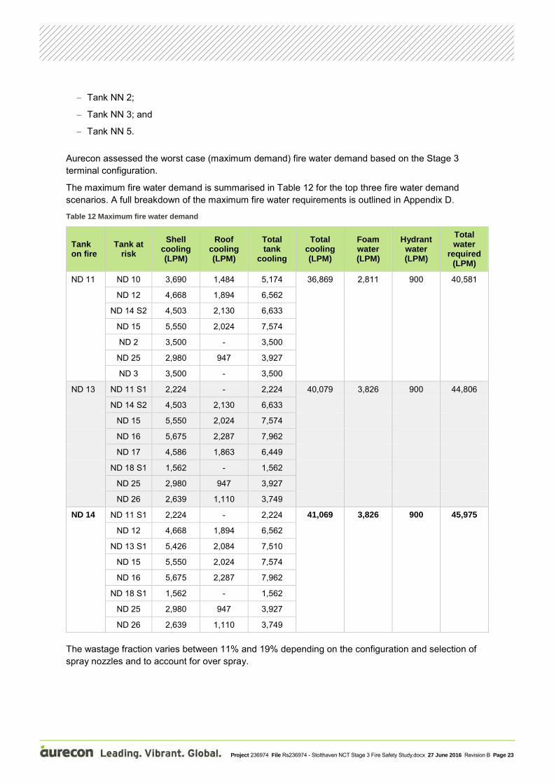
The maximum fire water demand is summarised in Table 12 for the top three fire water demand scenarios. A full breakdown of the maximum fire water requirements is outlined in Appendix D.
Table 12 Maximum fire water demand
Tank on fire
Tank at risk
Shell cooling (LPM)
Roof cooling (LPM)
Total tank
cooling
Total cooling (LPM)
Foam water (LPM)
Hydrant water (LPM)
Total water
required (LPM)
ND 11 ND 10 3,690 1,484 5,174 36,869 2,811 900 40,581
ND 12 4,668 1,894 6,562
ND 14 S2 4,503 2,130 6,633
ND 15 5,550 2,024 7,574
ND 2 3,500 - 3,500
ND 25 2,980 947 3,927
ND 3 3,500 - 3,500
ND 13 ND 11 S1 2,224 - 2,224 40,079 3,826 900 44,806
ND 14 S2 4,503 2,130 6,633
ND 15 5,550 2,024 7,574
ND 16 5,675 2,287 7,962
ND 17 4,586 1,863 6,449
ND 18 S1 1,562 - 1,562
ND 25 2,980 947 3,927
ND 26 2,639 1,110 3,749
ND 14 ND 11 S1 2,224 - 2,224 41,069 3,826 900 45,975
ND 12 4,668 1,894 6,562
ND 13 S1 5,426 2,084 7,510
ND 15 5,550 2,024 7,574
ND 16 5,675 2,287 7,962
ND 18 S1 1,562 - 1,562
ND 25 2,980 947 3,927
ND 26 2,639 1,110 3,749 The wastage fraction varies between 11% and 19% depending on the configuration and selection of spray nozzles and to account for over spray.

Project 236974 File Rs236974 - Stolthaven NCT Stage 3 Fire Safety Study.docx 27 June 2016 Revision B Page 24
8.2.4 Static fire water storage The worst case (maximum demand) fire water storage requirements for the Stage 3 works are outlined in Table 13.
Table 13 Static fire water storage requirement
Item Maximum Fire Water Demand (LPM)
Duration (minutes)
Maximum Fire Water Volume Required (L)
Cooling 41,069 90 3,696,165
Foam 3,826 55 210,448
Hydrants 900 240 216,000
Total 45,795 4,122,613
In order to provide the required storage capacity, two new fire water storage tanks, each with an effective capacity of 1.2 ML will be installed on LOT 36 as part of the Stage 3 works, bringing the total storage capacity to 4.8 ML.
The four fire water storage tanks will be hydraulically balanced via a DN250 cross connection line.
8.2.5 Activation As the site will be manned on a 24/7 basis by trained operators, the activation of the tank cooling and foam systems will be manual, with the position of the activation panel remote from the fire hazard. .
The level of risk reduction provided by a fully automated fire detection and initiation systems is not significant to warrant their installation. This is supported by the heat radiation modelling work, with the 8.0 kW/m2 heat radiation contour not reached at ground level and the 4.7 kW/m2 heat radiation contour: which is considered the threshold for safe operation of fire fighting equipment without protection, extending in most cases 15 m from the tank shell.
The Stage 3 terminal activation methodology will be as follows:
Tank cooling
− Deluge valves that branch off the hydrant ring main. Hydrant ring main pressure will hold the deluge valve in the closed position under normal terminal operations;
− Each deluge valve will be provided with a normally closed, magnetic latching (fail in last position) electric solenoid that will be operated from the fire system control panel;
− Upon activation of the solenoid, the control tubing that holds pressure on the deluge valve diaphragm will relieve to grade allowing the deluge valve to open and the cooling systems to operate.
Tank foam
− A foam solution ring main will run parallel to the hydrant ring main. The foam solution ring main will normally rest on foam solution. In order to assure the reliability of the held foam solution, annual foam sampling from three positions will be required;
− Foam deluge valves that branch off the foam solution ring main.
− A branch from the pressurised hydrant ring main will hold the foam deluge valve in the closed position under normal terminal operations;
− Each deluge valve will be provided with a normally closed, magnetic latching (fail in last position) electric solenoid that will be operated from the fire system control panel;
Project 236974 File Rs236974 - Stolthaven NCT Stage 3 Fire Safety Study.docx 27 June 2016 Revision B Page 25
− Upon activation of the solenoid, the control tubing that holds pressure on the deluge valve diaphragm will relieve to grade allowing the deluge valve to open and the cooling systems to operate;
− A pressure switch will be installed downstream of the foam deluge valve to provide positive feedback to the fire control panel.
Medium expansion foam pourers
− Where medium expansion foam pourers are required, they will operate as per the bulk tank foam systems.
Foam capable monitors
− All foam capable monitors will branch off the hydrant ring main and their operation will be as per the tank cooling systems
8.3 Water distribution system 8.3.1 Fire water pumps
8.3.2 Hydrant ring main In accordance with AS 1940 and AS 2419.1, dual outlet hydrant valves are required to be positioned along the hydrant main with a maximum spacing of 60 m. In addition, AS 1940 requires that hydrants are placed such that cooling water can be applied to all surfaces of every tank requiring cooling using a hose with length not exceeding 60 m.
AS 2419.1 also requires that sufficient isolation valves be installed on the hydrant main to ensure that in the event of pipework failure that at least 75% of the system be operable.
The hydrant piping will be sized to meet the following requirements:
Maximum velocity, assuming split flow, of 4 m/s
When the worst case (demand) fire scenario tank cooling, foam and hydrants are operating, the minimum residual pressure in the hydrant ring main will be greater than 700 kPa
Subject to agreement with the local fire brigade, and due to the fire water demands, it is proposed that a number of large bore Storz couplings (DN150) are installed on the hydrant ring main to provide additional flexibility in fire fighting.
8.4 Road loading gantry In accordance with NFPA 16, foam-water sprinkler systems are required to be designed for a discharge density of 6.5 LPM/m2 and a discharge duration of 10 minutes over the entire system area.
A summary of the fire protection requirements for the Stage 3 loading gantry is provided in Table 14.
Table 14 Foam requirements for the Gantries in accordance with NFPA 16
Bunded area Area (m2)
Foam density (LPM/m2)
Foam Solution flowrate (LPM)
3% Foam concentrate storage requirement (L)
Stage 3 loading gantry – entire gantry area 1,300 6.5 8,450 2,535
Stage 3 loading gantry – single bay 215 6.5 1,398 419
In order to provide the required flowrate of 8,450 LPM, and taking into consideration the bulk tank foam system requirements, it is proposed that a second Turbinator MIDI-PLUS be provided. The two units will operate in parallel to provide the required flowrate of foam solution to the loading gantry.

Project 236974 File Rs236974 - Stolthaven NCT Stage 3 Fire Safety Study.docx 27 June 2016 Revision B Page 26
8.4.1 Activation It is proposed to provide an automatic foam deluge system in the Gantry that will cover the entire gantry structure (area). This will be automatically operated by UVIR flame detectors in each unloading bay of the Gantry, these will operate on a voting system. The system will be able to be manually activated via push buttons that will be located at the exit of each gantry bay, at the terminal control room on LOT 2 and from the Stage 3 terminal pump house.
8.5 Vapour Recovery Unit The VRU has been identified as a potential fire scenario and due to it’s location to tank ND 12, it is proposed that a water cannon (monitor) is provided for cooling purposes. However as all monitors will be provided with a self-educting foam nozzle to allow flexibility, foam can also be applied to the VRU containment area if required.
The monitor will be provided with a nominal flowrate of 3,000 LPM.
8.6 Gantry spill pit Any spills within the loading gantry will pass to the gantry spill pit that is located to the south of the gantry operational area. The gantry spill pit has been identified as a potential fire scenario and as such, a medium expansion foam pourer will be provided to extinguish a pool fire in this area.
The design criteria for the gantry spill pit fire suppression system is as follows:
Application of foam to cover the pit area within 10 minutes;
A foam blanket thickness of 100 mm; and
Using medium expansion foam pourer with a minimum expansion ratio of 40:1.
Table 15 Foam requirements for gantry spill pit area
Bunded area Area (m2) Foam required (LPM)
Number of foam pourers
Gantry spill pit 99.8 25 1
The foam pourer will be remotely activated from the same control panel as the bulk storage tank cooling and foam systems.
8.7 Bunded area foam system Loss of containment scenarios were highlighted as a potential risk as part of the PHA. The loss of containment from a tank overfill is one of the scenarios identified as well as a catastrophic tank failure. In order to minimise the likelihood of a VCE, the suppression of vapour evolution can be achieved by the application of a foam blanket to the spilt product. For a tank overfill scenario, it is assumed that the spilt product is contained by the intermediate bunding provided around each bulk storage tank. For a catastrophic tank failure, it is assumed that the spilt product is contained by the main compound walls. Based on this, the design criteria is as follows:
Application of foam to cover the bunded area within 10 minutes;
A foam blanket thickness of 100 mm; and
Using medium expansion foam pourer with a minimum expansion ratio of 40:1.
The results are summarised in Table 16.
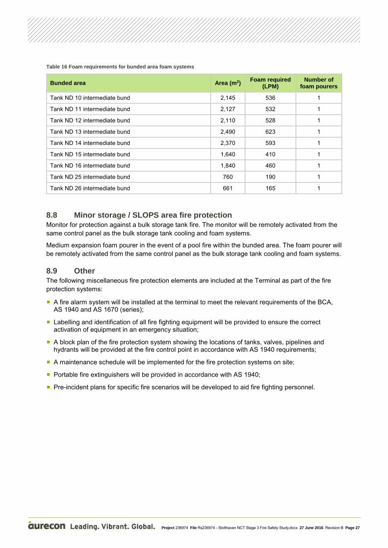
Project 236974 File Rs236974 - Stolthaven NCT Stage 3 Fire Safety Study.docx 27 June 2016 Revision B Page 27
Table 16 Foam requirements for bunded area foam systems
Bunded area Area (m2) Foam required (LPM)
Number of foam pourers
Tank ND 10 intermediate bund 2,145 536 1
Tank ND 11 intermediate bund 2,127 532 1
Tank ND 12 intermediate bund 2,110 528 1
Tank ND 13 intermediate bund 2,490 623 1
Tank ND 14 intermediate bund 2,370 593 1
Tank ND 15 intermediate bund 1,640 410 1
Tank ND 16 intermediate bund 1,840 460 1
Tank ND 25 intermediate bund 760 190 1
Tank ND 26 intermediate bund 661 165 1
8.8 Minor storage / SLOPS area fire protection Monitor for protection against a bulk storage tank fire. The monitor will be remotely activated from the same control panel as the bulk storage tank cooling and foam systems.
Medium expansion foam pourer in the event of a pool fire within the bunded area. The foam pourer will be remotely activated from the same control panel as the bulk storage tank cooling and foam systems.
8.9 Other The following miscellaneous fire protection elements are included at the Terminal as part of the fire protection systems:
A fire alarm system will be installed at the terminal to meet the relevant requirements of the BCA, AS 1940 and AS 1670 (series);
Labelling and identification of all fire fighting equipment will be provided to ensure the correct activation of equipment in an emergency situation;
A block plan of the fire protection system showing the locations of tanks, valves, pipelines and hydrants will be provided at the fire control point in accordance with AS 1940 requirements;
A maintenance schedule will be implemented for the fire protection systems on site;
Portable fire extinguishers will be provided in accordance with AS 1940;
Pre-incident plans for specific fire scenarios will be developed to aid fire fighting personnel.

Appendices

Appendix A Drawings
General Arrangement Drawing
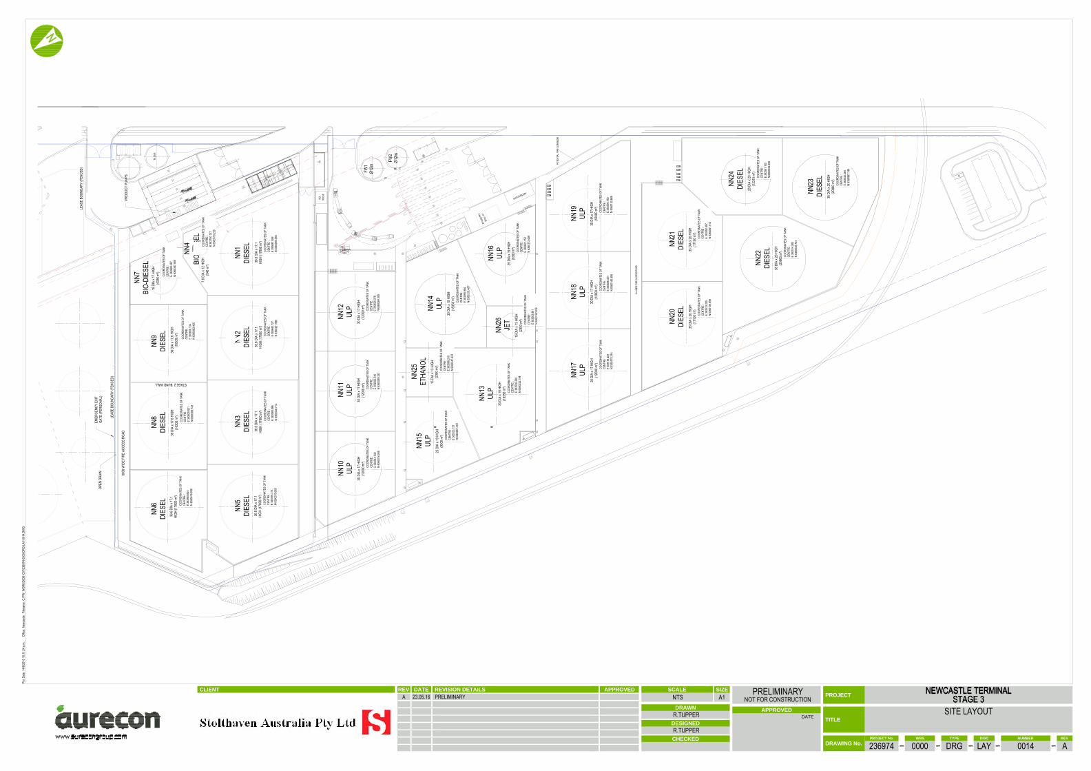
NN6
DIES
EL
NN7
BIO-
DIES
EL
NN1
DIES
ELNN
2DI
ESEL
NN3
DIES
ELNN
5DI
ESEL
LEAS
E BO
UNDA
RY (F
ENCE
D)
OPEN
DRA
INEM
ERGE
NCY
EXIT
GATE
(PER
SONA
L)
6000
WID
E FI
RE A
CCES
S RO
AD
LEAS
E BO
UNDA
RY (F
ENCE
D)
NN8
DIES
ELNN
9DI
ESEL
36 D
IA x
17.6
HIGH
(163
00 m
³)36
DIA
x 17
.6 HI
GH(1
6300
m³)
STAGE 2 BUND WALL
NN23
DIES
ELNN24
DIES
EL
NN22
DIES
EL
NN21
DIES
ELNN
20DI
ESEL
NN19
ULP
NN18
ULP
NN17
ULP
NN13
ULP
NN15
ULP
NN25
ETHA
NOL
NN14
ULP
NN26
JET
NN16
ULP
NN12
ULP
NN11
ULP
NN10
ULP
38 D
IA x
20 H
IGH
(209
60 m
³)
28 D
IA x
20 H
IGH
(123
15 m
³)
38 D
IA x
20 H
IGH
(209
60 m
³)33 D
IA x
20 H
IGH
(171
00 m
³)33
DIA
x 20
HIG
H(1
7100
m³)
30 D
IA x
17 H
IGH
(120
00 m
³)30
DIA
x 17
HIG
H(1
2000
m³)
30 D
IA x
17 H
IGH
(120
00 m
³)
25 D
IA x
19 H
IGH
(930
0 m³)
25 D
IA x
19 H
IGH
(930
0 m³)
15 D
IA x
13 H
IGH
(230
0 m³)
15 D
IA x
13 H
IGH
(230
0 m³)
30 D
IA x
19 H
IGH
(183
50 m
³)
30 D
IA x
19 H
IGH
(183
50 m
³)
30 D
IA x
17 H
IGH
(120
00 m
³)30
DIA
x 17
HIG
H(1
2000
m³)
30 D
IA x
17 H
IGH
(120
00 m
³)
36.6
DIA
x 17.1
HIGH
(178
00 m
³)
36.6
DIA
x 17.1
HIGH
(178
00 m
³)36
.6 DI
A x 1
7.1HI
GH (1
7800
m³)
36.6
DIA
x 17.1
HIGH
(178
00 m
³)36
.6 DI
A x 1
7.1HI
GH (1
7800
m³)
7.6 D
IA x
12 H
IGH
(546
m³)
18 D
IA x
17 H
IGH
(433
6 m³)
BIOD
IESE
L
PROD
UCT
PUMP
S
NN4
COOR
DINA
TES
OF T
ANK
CENT
RE :
E 38
3514
.282
N 63
6004
5.733
COOR
DINA
TES
OF T
ANK
CENT
RE :
E 38
3561
.105
N 63
6003
3.696
COOR
DINA
TES
OF T
ANK
CENT
RE :
E 38
3532
.284
N 63
5999
7.749
COOR
DINA
TES
OF T
ANK
CENT
RE :
E 38
3513
.205
N 63
6010
5.855
COOR
DINA
TES
OF T
ANK
CENT
RE :
E 38
3550
.457
N 63
6008
1.513
COOR
DINA
TES
OF T
ANK
CENT
RE :
E 38
3518
.483
N 63
6017
0.314
COOR
DINA
TES
OF T
ANK
CENT
RE :
E 38
3556
.321
N 63
6014
5.589
COOR
DINA
TES
OF T
ANK
CENT
RE :
E 38
3594
.159
N 63
6012
0.865
COOR
DINA
TES
OF T
ANK
CENT
RE :
E 38
3601
.152
N 63
6017
3.439
COOR
DINA
TES
OF T
ANK
CENT
RE :
E 38
3563
.961
N 63
6019
2.609
COOR
DINA
TES
OF T
ANK
CENT
RE :
E 38
3536
.260
N 63
6022
2.184
COOR
DINA
TES
OF T
ANK
CENT
RE :
E 38
3595
.984
N 63
6021
8.467
COOR
DINA
TES
OF T
ANK
CENT
RE :
E 38
3568
.210
N 63
6024
7.923
COOR
DINA
TES
OF T
ANK
CENT
RE :
E 38
3533
.157
N 63
6026
7.449
COOR
DINA
TES
OF T
ANK
CENT
RE :
E 38
3544
.702
N 63
6031
4.045
COOR
DINA
TES
OF T
ANK
CENT
RE :
E 38
3582
.540
N 63
6028
9.321
COOR
DINA
TES
OF T
ANK
CENT
RE :
E 38
3620
.378
N 63
6026
4.595
COOR
DINA
TES
OF T
ANK
CENT
RE :
E 38
3640
.727
N 63
6032
1.990
COOR
DINA
TES
OF T
ANK
CENT
RE :
E 38
3681
.559
N 63
6029
5.265
COOR
DINA
TES
OF T
ANK
CENT
RE :
E 38
3599
.896
N 63
6034
8.714
COOR
DINA
TES
OF T
ANK
CENT
RE :
E 38
3559
.215
N 63
6037
5.669
COOR
DINA
TES
OF T
ANK
CENT
RE :
E 38
3585
.624
N 63
6041
6.656
COOR
DINA
TES
OF T
ANK
CENT
RE :
E 38
3625
.921
N 63
6038
9.743
COOR
DINA
TES
OF T
ANK
CENT
RE :
E 38
3666
.134
N 63
6036
3.425
COOR
DINA
TES
OF T
ANK
CENT
RE :
E 38
3698
.487
N 63
6034
7.500
COOR
DINA
TES
OF T
ANK
CENT
RE :
E 38
3700
.137
N 63
6031
9.229
CLIENT
DATE
TITLE
REVISION DETAILSDATEREV APPROVED
CHECKED
APPROVED
PROJECT
DRAWN
DESIGNED
PROJECT No. TYPE REVWBS DISC NUMBER
DRAWING No.
SCALE SIZE
A1
.
NEWCASTLE TERMINALSTAGE 3
NEWCASTLE TERMINALSTAGE 3
SITE LAYOUT
236974 0000 DRG LAY 0014 A
NTSPRELIMINARY
NOT FOR CONSTRUCTION
R.TUPPER
R.TUPPER
A 23.05.16 PRELIMINARY
Filen
ame:
Plot
Date:
Offic
e:C:
\PW
_WOR
K\D0
3010
07\23
6974
-000
0-DR
G-LA
Y-00
14.D
WG
14/6/
2016
10:11
:24 a.
m.Ne
wcas
tle

Appendix B HAZOP 11045 Rev 1
Stolthaven Australia Pty ltd
HAZOP Report & Risk Assessment Newcastle Terminal Stage 3 Port Authority of New South Wales 3/4/5 March 2015 (Workshop 1) & 2/3/4 May 2016 (Workshop 2)
Report No: 11045 Rev 1A for Comment
17 May 2016 Cockshott Consulting Engineers Pty Ltd
ACN 005 754 325 17 Margaret St East Brighton 3187 Tel: (03) 9593 1589 Author: John Cockshott FIChemE FIE(Aust) CEng CPEng RPEQ NER BSc(Eng) ACGI Professional Process Safety Engineer
Cockshott Consulting Engineers 2 Report No: 11045 Rev 1A for comment: 17 May 2016
Contents: Executive Summary ......................................................................................................................................... 3 1 Introduction ............................................................................................................................................ 5 2 Basis of HAZID and Risk Assessment ....................................................................................................... 6
2.1 Site location and layout ................................................................................................................. 6 2.2 Products ......................................................................................................................................... 6 2.3 Storage Tank Configuration ........................................................................................................... 7 2.4 Wharf Lines .................................................................................................................................... 7 2.5 Marine Discharge, Export & Load out Movements and Quantities ............................................... 8 2.6 Operations at the Berth ................................................................................................................. 8 2.7 Properties & Hazardous Data of Cargos ......................................................................................... 8 2.8 Meteorological data ....................................................................................................................... 8 2.9 Technical Drawings reviewed in the HAZOP ................................................................................ 10
2.9.1 Process Flow Diagrams (Workshop 1) ..................................................................................... 10 2.9.2 Piping & Instrument Drawings (Workshop 1) .......................................................................... 10 2.9.3 Piping & Instrument Drawings (Workshop 2) .......................................................................... 11 2.9.4 Layout Drawings (Workshop 1) ............................................................................................... 11
3 Consequence Impact Criteria ................................................................................................................ 16 3.1 HIPAP No 4 ................................................................................................................................... 16 3.2 HIPAP 4 Risk Criteria – Fatality and Injury Criteria ....................................................................... 16 3.3 Acute Exposure Guideline Levels ................................................................................................. 17 3.4 HIPAP 4 Environmental Impacts .................................................................................................. 18 3.5 Stolthaven Risk Criteria ................................................................................................................ 18
3.5.1 Safety Risks .............................................................................................................................. 19 3.5.2 Environmental, Quality, Commercial and Reputation Risks .................................................... 19 3.5.3 Risk Ranking ............................................................................................................................. 19
3.6 Probability Bow‐Ties .................................................................................................................... 21 3.7 Thermal Radiation ........................................................................................................................ 21 3.8 Blast Effects .................................................................................................................................. 21 3.9 So Far As is Reasonably Practical ................................................................................................. 22
4 Hazard Identification & HAZOP Notes ...................................................... Error! Bookmark not defined. 5 HAZOP Notes (3, 4 & 5 March 2015) .................................................................................................... 25 6 HAZOP Notes (2, 3 &4 May 2016) ......................................................................................................... 81 7 HAZOP Action List ................................................................................................................................. 80 8 Model Parameters .............................................................................................................................. 125 9 Consequence Analysis......................................................................................................................... 127
9.4 Wharf Fires ................................................................................................................................. 132 9.5 Wharf Spill Resulting in a Flash Fire ........................................................................................... 133 9.6 Terminal Tank Fires .................................................................................................................... 133 9.7 Tank Loss of Containment .......................................................................................................... 134
9.7.1 Tank Loss of Containment (Moderate) .................................................................................. 134 9.7.2 Tank Loss of Containment (Large) ......................................................................................... 136
10 Frequency Analysis ............................................................................................................................. 138 11 Risk Assessment .................................................................................................................................. 143
11.1 Ammonium Nitrate Explosion (AN Facility or K2 Berth) ............................................................ 144 11.2 External Fire (Bulk Coal Carrier) ................................................................................................. 144 11.3 Bulk Fuels Wharf and Terminal Operations ............................................................................... 144
12 Abbreviations ...................................................................................................................................... 145 Appendix A: Drawings (First HAZOP 3/4/5 2015) ........................................................................................ 147 Appendix B: Drawings (Second HAZOP 2/3/4 May 2016)) .......................................................................... 148 Appendix C: Probability Bow‐Ties (Newcastle Terminal Stage 3) ................................................................ 149
Cockshott Consulting Engineers 3 Report No: 11045 Rev 1A for comment: 17 May 2016
Executive Summary
Stolthaven Australia Pty Ltd (Stolthaven) has entered into leases with The Port of Newcastle (PON). The terminal is already operating with diesel and biodiesel products on Lot 2.
Stolthaven is in the construction phase of a purpose‐built bulk liquids berth (Mayfield M7) and in the approval stage for the Stage 3 Development of the shore leases (lots 36 & 37). Stolthaven will own and operate the berth and terminal in accordance with its lease obligations.
The current HAZOP and Risk Assessment covers Stage 3 of the terminal development and is based on the present understanding of committed and forward‐looking customer requirements. The product slate is included as Table 5 Marine & Loading Bay Movements. The HAZOP is based on a conceptual layout for Stage 3 though the final details and staging of construction will depend on firm customer commitments.
Currently, the terminal receives parcels from marine tankers, stores and loads to road tankers both diesel and biodiesel products using Mayfield Berth 4A for marine discharge. The expansion will increase current diesel storage capacity and provide additional storage for unleaded petrol, ethanol and jet fuel. All products will be discharged from the new Mayfield 7 Berth. As the storage quantities likely to be present after the expansion exceed the threshold quantity of Schedule 15 of the Work Health & Safety Regulations 2011 (WHSR 2011), the terminal will be licensed as a Major Hazard Facility.
A HAZOP conducted on 3/4/5 March 2015 was the first phase of a detailed Quantitative Risk Assessment (QRA) process for the terminal. Previous preliminary process hazard analysis has included both berth and terminal operations (to Stage 2) based on preliminary design. Outcomes of these preliminary studies have been incorporated progressively in the design. The Preliminary Hazard Analysis (PHA) which formed part of the Development Application (DA) was based on Probability Bow‐Ties1 (PBTs) developed using the results of this HAZOP.
A second Stage 3 HAZOP was conducted on 2/3/4 May 2016 covering additional Biodiesel, Additives and Slops tanks, and the further development of the Vapour Recovery Unit (VRU) and Drainage System
The primary purpose was to identify those events that may lead to the exposure of a person to a serious risk to health or safety. The HAZOP Guidewords include initiating events that may lead to loss of containment, explosion and fire. As an integral part of the workshop, a previous HAZID Study (Report 11039) for the preliminary design of the berth and a previous HAZID Study (Report 11043) for the preliminary design of the terminal for Stage 3 were reviewed. The current HAZOP Report therefore represents a consolidation of all previous process hazard analysis studies, and as input to the QRA..
The design is not finalised and there are a number of technical decisions yet to be made. As the design develops, additional Process Hazard Analysis (PHA) processes (such as final HAZOP and SFARP studies) will be conducted, and these will feed into the terminal safety management system, the QRA and Safety Case.
The report is structured as follows:
Section 1 of this report provides background information.
Section 2 provides the basis for the HAZOP and risk assessment and states the assumptions made.
Section 3 covers the risk criteria applied for risk assessment.
Section Error! Reference source not found. covers methodology and records workshop team members
Sections 5 to 6 contain the HAZOP Workshop Notes.
Section 7 provides the HAZOP Action List.
Section 8 identifies significant model parameters used in pool fire modelling
Section 9 summarises consequence analysis for the hazardous scenarios identified in the HAZID.
Section 10 provides the basis of probability of the initiation of hazardous events.
Section 11 presents the risk assessment for the identified hazardous events and their adverse outcomes. This section includes Probability Bow Ties which link the initiating events preventative and mitigative safeguards through to the potentially adverse outcomes and final risk assessment. Conformance with HIPAP 4 is covered in this Section.
1 Probability Bow –Ties A Transparent Risk Management Tool, J E Cockshott, Trans IChemE, Part B, July 2005, Process Safety and Environmental Protection, 83(B4):307‐316

Cockshott Consulting Engineers 4 Report No: 11045 Rev 1A for comment: 17 May 2016
Assuming that all recommendations are followed, the proposed design and operation of the terminal meet both Stolthaven and HIPAP No 4 criteria for employees, the public and the environment.

Cockshott Consulting Engineers 5 Report No: 11045 Rev 1A for comment: 17 May 2016
1 Introduction
Stolthaven Australia Pty Ltd (Stolthaven) has entered into leases with The Port of Newcastle (PON). The terminal is already operating with diesel and biodiesel products on Lot 2.
Stolthaven is in the construction phase of a purpose‐built bulk liquids berth (Mayfield M7) and in the approval stage for the Stage 3 Development of the shore leases (lots 36 & 37). Stolthaven will own and operate the berth and terminal in accordance with its lease obligations.
The current HAZOP and Risk Assessment covers Stage 3 of the terminal development and is based on the present understanding of committed and forward‐looking customer requirements. The product slate is included as Table 5 Marine & Loading Bay Movements. The HAZOP is based on a conceptual layout for Stage 3 though the final details and staging of construction will depend on firm customer commitments.
Currently, the terminal receives parcels from marine tankers, stores and loads to road tankers both diesel and biodiesel products using Mayfield Berth 4A for marine discharge. The expansion will increase current diesel storage capacity and provide additional storage for unleaded petrol, ethanol and jet fuel. All products will be discharged from the new Mayfield 7 Berth. As the storage quantities likely to be present after the expansion exceed the threshold quantity of Schedule 15 of the Work Health & Safety Regulations 2011 (WHSR 2011), the terminal will be licensed as a Major Hazard Facility.
A HAZOP conducted on 3/4/5 March 2015 was the first phase of a detailed Quantitative Risk Assessment (QRA) process for the terminal. Previous preliminary process hazard analysis has included both berth and terminal operations (to Stage 2) based on preliminary design. Outcomes of these preliminary studies have been incorporated progressively in the design. The Preliminary Hazard Analysis (PHA) which formed part of the Development Application (DA) was based on Probability Bow‐Ties2 (PBTs) developed using the results of this HAZOP.
A second Stage 3 HAZOP was conducted on 2/3/4 May 2016 covering additional Biodiesel, Additives and Slops tanks, and the further development of the Vapour Recovery Unit (VRU) and Drainage System.
A HAZOP is a structured workshop where possible deviations from the intent of the design and proposed operations are postulated, potential causes are identified and current safeguards are recorded. For this HAZOP, Stolthaven assembled an experienced team of bulk liquids terminal designers, project and operations personnel who have had many years of experience in the planning, design, construction and operation of bulk liquids terminals and associated facilities. The workshop was facilitated by the author.
As an integral part of the workshop, a previous HAZID Study (Report 11039) for the preliminary design of the berth and a previous HAZID Study (Report 11043) for the preliminary design of the terminal for Stage 3 were reviewed. The current HAZOP Report therefore represents a consolidation of all previous process hazard analysis studies, and a starting point for the QRA.
The potential consequence(s) of each adverse event was discussed and recorded as well as experienced estimates made for the probability of failure‐on‐demand (PFD) of the safeguards. Requirements for further analysis of consequences and risk were identified.
A semi‐quantitative risk assessment (SQRA) is made using input metrics from the HAZOP participants and authoritative failure rate data. Use of historical failure data alone has the disadvantage that it estimates risk for average facilities under average management – the results of such analysis are of little value for use in driving design and operational parameters. Most accidents involved in ship unloading or export operations are the result of systemic or operational failures. By focussing the HAZOP on potential adverse events caused by failures of safeguards, risk improvements can be made at the conceptual stage and incorporated into inherently safer design and operation.
Following the HAZOP workshop, consequence analysis was prepared for the identified adverse scenarios and risk assessments were prepared. Use was made of PBTs representing the complex interaction of initiating events, preventative and mitigative safeguards as credible chains‐of‐events.
The scope of the HAZOP and Risk Assessment Report covers the design and operation of the wharf topsides and terminal but excludes construction activities.
2 Probability Bow –Ties A Transparent Risk Management Tool, J E Cockshott, Trans IChemE, Part B, July 2005, Process Safety and Environmental Protection, 83(B4):307‐316
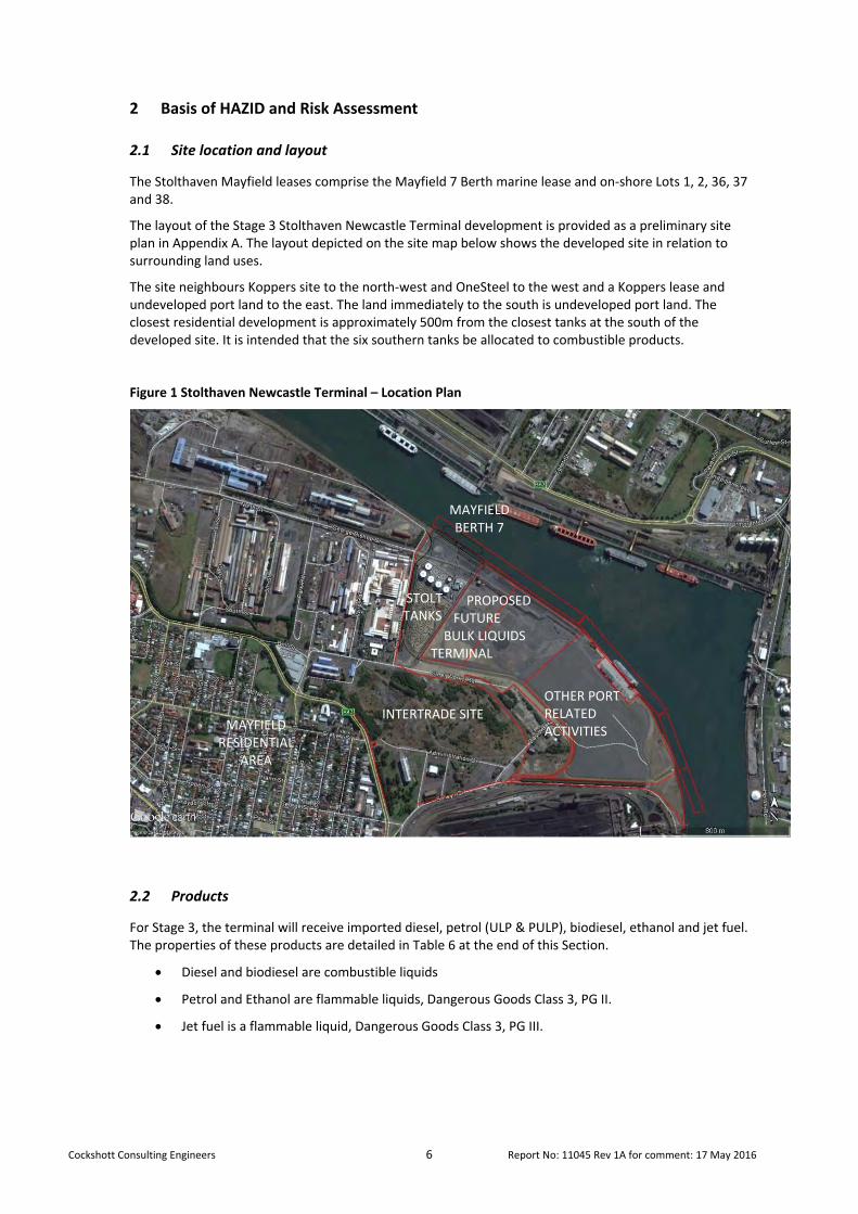
Cockshott Consulting Engineers 6 Report No: 11045 Rev 1A for comment: 17 May 2016
2 Basis of HAZID and Risk Assessment
2.1 Site location and layout
The Stolthaven Mayfield leases comprise the Mayfield 7 Berth marine lease and on‐shore Lots 1, 2, 36, 37 and 38.
The layout of the Stage 3 Stolthaven Newcastle Terminal development is provided as a preliminary site plan in Appendix A. The layout depicted on the site map below shows the developed site in relation to surrounding land uses.
The site neighbours Koppers site to the north‐west and OneSteel to the west and a Koppers lease and undeveloped port land to the east. The land immediately to the south is undeveloped port land. The closest residential development is approximately 500m from the closest tanks at the south of the developed site. It is intended that the six southern tanks be allocated to combustible products.
Figure 1 Stolthaven Newcastle Terminal – Location Plan
2.2 Products
For Stage 3, the terminal will receive imported diesel, petrol (ULP & PULP), biodiesel, ethanol and jet fuel. The properties of these products are detailed in Table 6 at the end of this Section.
Diesel and biodiesel are combustible liquids
Petrol and Ethanol are flammable liquids, Dangerous Goods Class 3, PG II.
Jet fuel is a flammable liquid, Dangerous Goods Class 3, PG III.
MAYFIELDBERTH 7
STOLTTANKS
PROPOSED FUTURE BULK LIQUIDS TERMINAL
OTHER PORT RELATED ACTIVITIES
INTERTRADE SITE MAYFIELD
RESIDENTIAL AREA
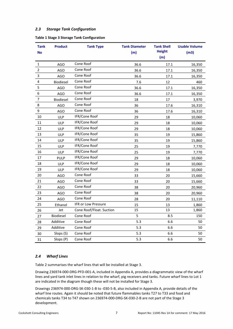
Cockshott Consulting Engineers 7 Report No: 11045 Rev 1A for comment: 17 May 2016
2.3 Storage Tank Configuration
Table 1 Stage 3 Storage Tank Configuration
Tank
No
Product Tank Type Tank Diameter
(m)
Tank Shell Height
(m)
Usable Volume
(m3)
1 AGO Cone Roof 36.6 17.1 16,350
2 AGO Cone Roof 36.6 17.1 16,350
3 AGO Cone Roof 36.6 17.1 16,350
4 Biodiesel Cone Roof 7.6 12 460
5 AGO Cone Roof 36.6 17.1 16,350
6 AGO Cone Roof 36.6 17.1 16,350
7 Biodiesel Cone Roof 18 17 3,970
8 AGO Cone Roof 36 17.6 16,310
9 AGO Cone Roof 36 17.6 16,310
10 ULP IFR/Cone Roof 29 18 10,060
11 ULP IFR/Cone Roof 29 18 10,060
12 ULP IFR/Cone Roof 29 18 10,060
13 ULP IFR/Cone Roof 35 19 15,860
14 ULP IFR/Cone Roof 35 19 15,860
15 ULP IFR/Cone Roof 25 19 7,770
16 ULP IFR/Cone Roof 25 19 7,770
17 PULP IFR/Cone Roof 29 18 10,060
18 ULP IFR/Cone Roof 29 18 10,060
19 ULP IFR/Cone Roof 29 18 10,060
20 AGO Cone Roof 33 20 15,660
21 AGO Cone Roof 33 20 15,660
22 AGO Cone Roof 38 20 20,960
23 AGO Cone Roof 38 20 20,960
24 AGO Cone Roof 28 20 11,110
25 Ethanol IFR or Low Pressure 15 13 1,860
26 Jet Cone Roof/Float. Suction 15 13 1,860
27 Biodiesel Cone Roof 5 8.5 150
28 Additive Cone Roof 5.3 6.6 50
29 Additive Cone Roof 5.3 6.6 50
30 Slops (S) Cone Roof 5.3 6.6 50
31 Slops (P) Cone Roof 5.3 6.6 50
2.4 Wharf Lines
Table 2 summarises the wharf lines that will be installed at Stage 3.
Drawing 236974‐000‐DRG‐PFD‐001‐A, included in Appendix A, provides a diagrammatic view of the wharf lines and yard tank inlet lines in relation to the wharf, pig receivers and tanks. Future wharf lines to Lot 1 are indicated in the diagram though these will not be installed for Stage 3.
Drawings 236974‐000‐DRG‐SK‐030‐1‐B to ‐030‐5‐B, also included in Appendix A, provide details of the wharf line routes. Again it should be noted that future flammables tanks T27 to T33 and food and chemicals tanks T34 to T47 shown on 236974‐000‐DRG‐SK‐030‐2‐B are not part of the Stage 3 development.
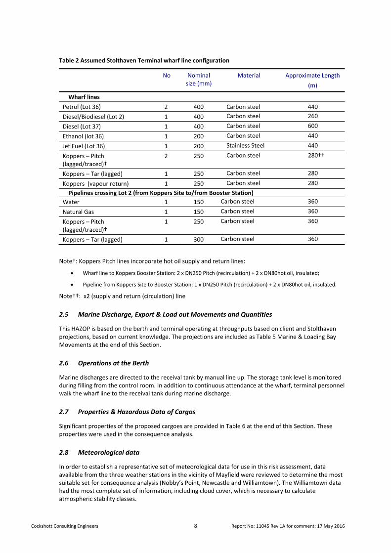
Cockshott Consulting Engineers 8 Report No: 11045 Rev 1A for comment: 17 May 2016
Table 2 Assumed Stolthaven Terminal wharf line configuration
No Nominal size (mm)
Material Approximate Length
(m)
Wharf lines
Petrol (Lot 36) 2 400 Carbon steel 440
Diesel/Biodiesel (Lot 2) 1 400 Carbon steel 260
Diesel (Lot 37) 1 400 Carbon steel 600
Ethanol (lot 36) 1 200 Carbon steel 440
Jet Fuel (Lot 36) 1 200 Stainless Steel 440
Koppers – Pitch (lagged/traced)†
2 250 Carbon steel 280††
Koppers – Tar (lagged) 1 250 Carbon steel 280
Koppers (vapour return) 1 250 Carbon steel 280
Pipelines crossing Lot 2 (from Koppers Site to/from Booster Station)
Water 1 150 Carbon steel 360
Natural Gas 1 150 Carbon steel 360
Koppers – Pitch (lagged/traced)†
1 250 Carbon steel 360
Koppers – Tar (lagged) 1 300 Carbon steel 360
Note†: Koppers Pitch lines incorporate hot oil supply and return lines:
Wharf line to Koppers Booster Station: 2 x DN250 Pitch (recirculation) + 2 x DN80hot oil, insulated;
Pipeline from Koppers Site to Booster Station: 1 x DN250 Pitch (recirculation) + 2 x DN80hot oil, insulated.
Note††: x2 (supply and return (circula on) line
2.5 Marine Discharge, Export & Load out Movements and Quantities
This HAZOP is based on the berth and terminal operating at throughputs based on client and Stolthaven projections, based on current knowledge. The projections are included as Table 5 Marine & Loading Bay Movements at the end of this Section.
2.6 Operations at the Berth
Marine discharges are directed to the receival tank by manual line up. The storage tank level is monitored during filling from the control room. In addition to continuous attendance at the wharf, terminal personnel walk the wharf line to the receival tank during marine discharge.
2.7 Properties & Hazardous Data of Cargos
Significant properties of the proposed cargoes are provided in Table 6 at the end of this Section. These properties were used in the consequence analysis.
2.8 Meteorological data
In order to establish a representative set of meteorological data for use in this risk assessment, data available from the three weather stations in the vicinity of Mayfield were reviewed to determine the most suitable set for consequence analysis (Nobby’s Point, Newcastle and Williamtown). The Williamtown data had the most complete set of information, including cloud cover, which is necessary to calculate atmospheric stability classes.
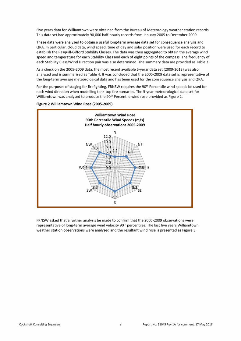
Cockshott Consulting Engineers 9 Report No: 11045 Rev 1A for comment: 17 May 2016
Five years data for Williamtown were obtained from the Bureau of Meteorology weather station records. This data set had approximately 90,000 half‐hourly records from January 2005 to December 2009.
These data were analysed to obtain a useful long‐term average data set for consequence analysis and QRA. In particular, cloud data, wind speed, time of day and solar position were used for each record to establish the Pasquill‐Gifford Stability Classes. The data was then aggregated to obtain the average wind speed and temperature for each Stability Class and each of eight points of the compass. The frequency of each Stability Class/Wind Direction pair was also determined. The summary data are provided as Table 3.
As a check on the 2005‐2009 data, the most recent available 5‐yerar data set (2009‐2013) was also analysed and is summarised as Table 4. It was concluded that the 2005‐2009 data set is representative of the long‐term average meteorological data and has been used for the consequence analysis and QRA.
For the purposes of staging for firefighting, FRNSW requires the 90th Percentile wind speeds be used for each wind direction when modelling tank‐top fire scenarios. The 5‐year meteorological data set for Williamtown was analysed to produce the 90th Percentile wind rose provided as Figure 2.
Figure 2 Williamtown Wind Rose (2005‐2009)
FRNSW asked that a further analysis be made to confirm that the 2005‐2009 observations were representative of long‐term average wind velocity 90th percentiles. The last five years Williamtown weather station observations were analysed and the resultant wind rose is presented as Figure 3.
4.2 6.1
7.8
8.3
9.2
8.3
9.2
8.3
0.0
2.0
4.0
6.0
8.0
10.0
12.0N
NE
E
SE
S
SW
W
NW
Williamtown Wind Rose90th Percentile Wind Speeds (m/s)Half hourly observations 2005‐2009
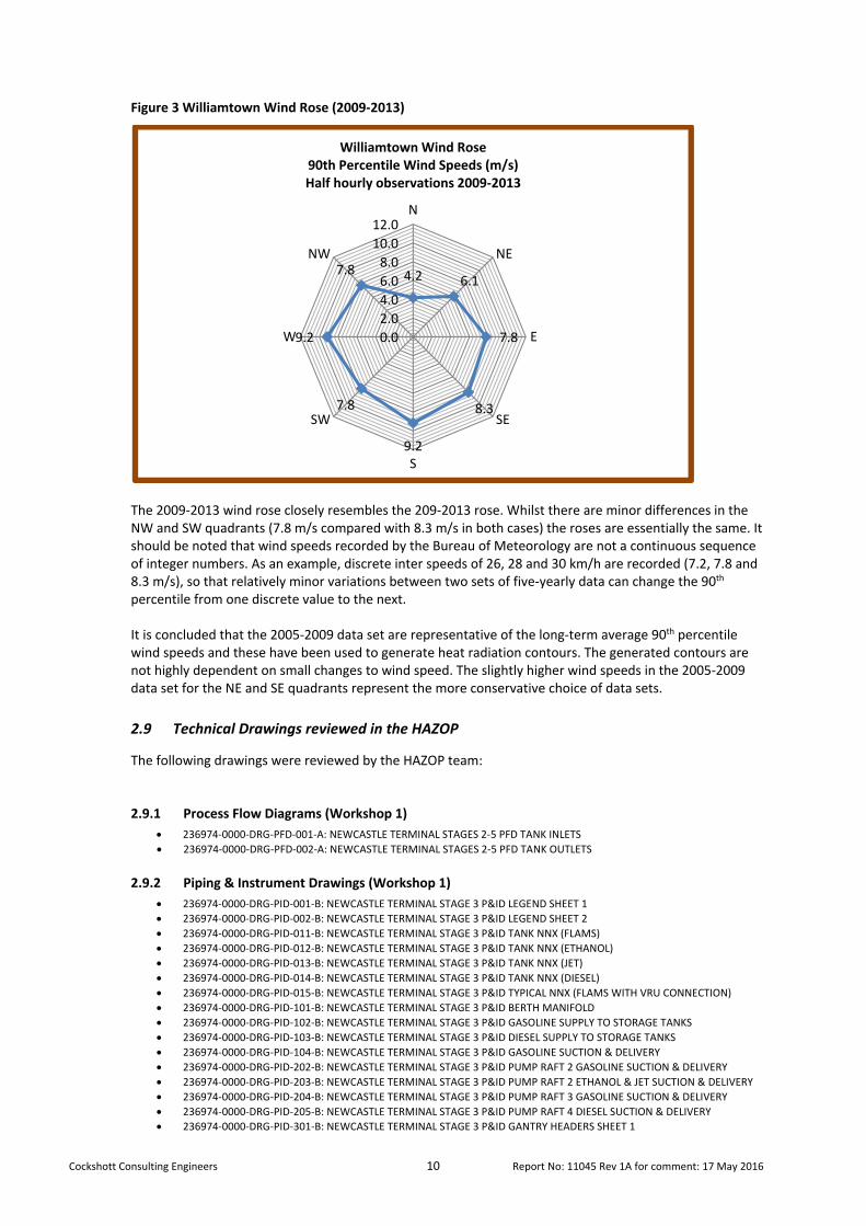
Cockshott Consulting Engineers 10 Report No: 11045 Rev 1A for comment: 17 May 2016
Figure 3 Williamtown Wind Rose (2009‐2013)
The 2009‐2013 wind rose closely resembles the 209‐2013 rose. Whilst there are minor differences in the NW and SW quadrants (7.8 m/s compared with 8.3 m/s in both cases) the roses are essentially the same. It should be noted that wind speeds recorded by the Bureau of Meteorology are not a continuous sequence of integer numbers. As an example, discrete inter speeds of 26, 28 and 30 km/h are recorded (7.2, 7.8 and 8.3 m/s), so that relatively minor variations between two sets of five‐yearly data can change the 90th percentile from one discrete value to the next. It is concluded that the 2005‐2009 data set are representative of the long‐term average 90th percentile wind speeds and these have been used to generate heat radiation contours. The generated contours are not highly dependent on small changes to wind speed. The slightly higher wind speeds in the 2005‐2009 data set for the NE and SE quadrants represent the more conservative choice of data sets.
2.9 Technical Drawings reviewed in the HAZOP
The following drawings were reviewed by the HAZOP team:
2.9.1 Process Flow Diagrams (Workshop 1)
236974‐0000‐DRG‐PFD‐001‐A: NEWCASTLE TERMINAL STAGES 2‐5 PFD TANK INLETS
236974‐0000‐DRG‐PFD‐002‐A: NEWCASTLE TERMINAL STAGES 2‐5 PFD TANK OUTLETS
2.9.2 Piping & Instrument Drawings (Workshop 1)
236974‐0000‐DRG‐PID‐001‐B: NEWCASTLE TERMINAL STAGE 3 P&ID LEGEND SHEET 1
236974‐0000‐DRG‐PID‐002‐B: NEWCASTLE TERMINAL STAGE 3 P&ID LEGEND SHEET 2
236974‐0000‐DRG‐PID‐011‐B: NEWCASTLE TERMINAL STAGE 3 P&ID TANK NNX (FLAMS)
236974‐0000‐DRG‐PID‐012‐B: NEWCASTLE TERMINAL STAGE 3 P&ID TANK NNX (ETHANOL)
236974‐0000‐DRG‐PID‐013‐B: NEWCASTLE TERMINAL STAGE 3 P&ID TANK NNX (JET)
236974‐0000‐DRG‐PID‐014‐B: NEWCASTLE TERMINAL STAGE 3 P&ID TANK NNX (DIESEL)
236974‐0000‐DRG‐PID‐015‐B: NEWCASTLE TERMINAL STAGE 3 P&ID TYPICAL NNX (FLAMS WITH VRU CONNECTION)
236974‐0000‐DRG‐PID‐101‐B: NEWCASTLE TERMINAL STAGE 3 P&ID BERTH MANIFOLD
236974‐0000‐DRG‐PID‐102‐B: NEWCASTLE TERMINAL STAGE 3 P&ID GASOLINE SUPPLY TO STORAGE TANKS
236974‐0000‐DRG‐PID‐103‐B: NEWCASTLE TERMINAL STAGE 3 P&ID DIESEL SUPPLY TO STORAGE TANKS
236974‐0000‐DRG‐PID‐104‐B: NEWCASTLE TERMINAL STAGE 3 P&ID GASOLINE SUCTION & DELIVERY
236974‐0000‐DRG‐PID‐202‐B: NEWCASTLE TERMINAL STAGE 3 P&ID PUMP RAFT 2 GASOLINE SUCTION & DELIVERY
236974‐0000‐DRG‐PID‐203‐B: NEWCASTLE TERMINAL STAGE 3 P&ID PUMP RAFT 2 ETHANOL & JET SUCTION & DELIVERY
236974‐0000‐DRG‐PID‐204‐B: NEWCASTLE TERMINAL STAGE 3 P&ID PUMP RAFT 3 GASOLINE SUCTION & DELIVERY
236974‐0000‐DRG‐PID‐205‐B: NEWCASTLE TERMINAL STAGE 3 P&ID PUMP RAFT 4 DIESEL SUCTION & DELIVERY
236974‐0000‐DRG‐PID‐301‐B: NEWCASTLE TERMINAL STAGE 3 P&ID GANTRY HEADERS SHEET 1
4.2 6.1
7.8
8.3
9.2
7.8
9.2
7.8
0.0
2.0
4.0
6.0
8.0
10.0
12.0N
NE
E
SE
S
SW
W
NW
Williamtown Wind Rose90th Percentile Wind Speeds (m/s)Half hourly observations 2009‐2013

Cockshott Consulting Engineers 11 Report No: 11045 Rev 1A for comment: 17 May 2016
236974‐0000‐DRG‐PID‐302‐B: NEWCASTLE TERMINAL STAGE 3 P&ID GANTRY HEADERS SHEET 2
236974‐0000‐DRG‐PID‐401‐B: NEWCASTLE TERMINAL STAGE 3 P&ID TRUCK LOADING BAY 1
236974‐0000‐DRG‐PID‐402‐B: NEWCASTLE TERMINAL STAGE 3 P&ID TRUCK LOADING BAY 2
236974‐0000‐DRG‐PID‐403‐B: NEWCASTLE TERMINAL STAGE 3 P&ID TRUCK LOADING BAY 3
236974‐0000‐DRG‐PID‐404‐B: NEWCASTLE TERMINAL STAGE 3 P&ID TRUCK LOADING BAY 4
236974‐0000‐DRG‐PID‐501‐B: NEWCASTLE TERMINAL STAGE 3 P&ID DEWATERING & SLOPS
236974‐0000‐DRG‐PID‐502‐B: NEWCASTLE TERMINAL STAGE 3 P&ID DRAINAGE
236974‐0000‐DRG‐PID‐601‐B: NEWCASTLE TERMINAL STAGE 3 P&ID VAPOUR RECOVERY UNIT
236974‐0000‐DRG‐PID‐105‐B: NEWCASTLE TERMINAL STAGE 3 P&ID DIESEL TIE‐IN TO EXISTING STAGE 1
2.9.3 Piping & Instrument Drawings (Workshop 2)
236974‐0000‐DRG‐PID‐501‐E: NEWCASTLE TERMINAL STAGE 3 P&ID DEWATERING & SLOPS
236974‐0000‐DRG‐PID‐502‐D: NEWCASTLE TERMINAL STAGE 3 P&ID DRAINAGE
236974‐0000‐DRG‐PID‐601‐E: NEWCASTLE TERMINAL STAGE 3 P&ID VAPOUR RECOVERY UNIT
236974‐0000‐DRG‐PID‐051‐B: NEWCASTLE TERMINAL STAGE 3 P&ID TANK NN27 BIODIESEL TANK
236974‐0000‐DRG‐PID‐052‐B: NEWCASTLE TERMINAL STAGE 3 P&ID TANK ND28 PUMA ADDITIVE TANK
236974‐0000‐DRG‐PID‐053‐B: NEWCASTLE TERMINAL STAGE 3 P&ID TANK ND29 STOLTHAVEN ADDITIVE TANK
2.9.4 Layout Drawings (Workshop 1)
236974‐SK‐027‐1‐REV 1
236974‐SK‐027‐2 REV 1
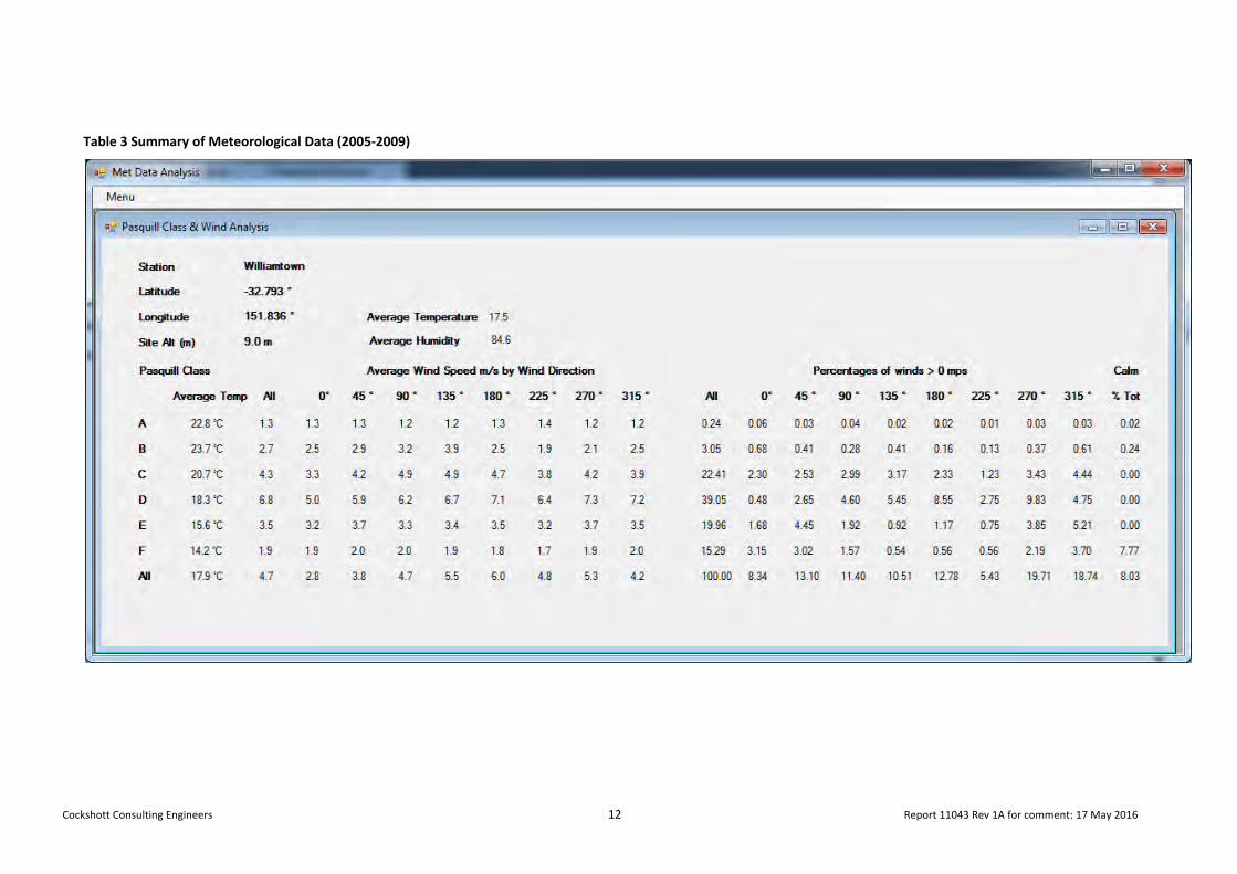
Cockshott Consulting Engineers 12 Report 11043 Rev 1A for comment: 17 May 2016
Table 3 Summary of Meteorological Data (2005‐2009)
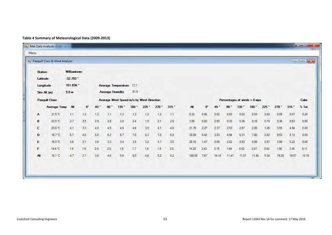
Cockshott Consulting Engineers 13 Report 11043 Rev 1A for comment: 17 May 2016
Table 4 Summary of Meteorological Data (2009‐2013)
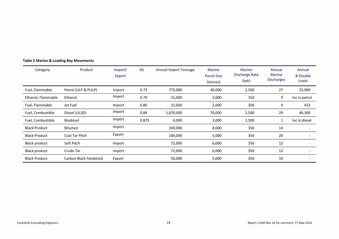
Cockshott Consulting Engineers 14 Report 11043 Rev 1A for comment: 17 May 2016
Table 5 Marine & Loading Bay Movements
Category Product Import/
Export
SG Annual Import Tonnage Marine
Parcel Size
(tonnes)
Marine Discharge Rate
(tph)
Annual Marine
Discharges
Annual
B‐Double Loads
Fuel, Flammable Petrol (ULP & PULP) Import 0.72 775,000 40,000 2,500 27 25,900
Ethanol, Flammable Ethanol Import 0.79 15,000 2,000 350 9 Inc in petrol
Fuel, Flammable Jet Fuel Import 0.80 15,000 2,000 350 9 433
Fuel, Combustible Diesel (ULSD) Import 0.84 1,670,000 70,000 2,500 29 46,300
Fuel, Combustible Biodiesel Import 0.875 4,000 3,000 1,500 1 Inc in diesel
Black Product Bitumen Import 100,000 8,000 350 14 ‐
Black Product Coal Tar Pitch Export 100,000 5,000 350 20 ‐
Black product Soft Pitch Import 72,000 6,000 350 12 ‐
Black product Crude Tar Import 72,000 6,000 350 12 ‐
Black Product Carbon Black Feedstock Export 50,000 5,000 350 10 ‐

Cockshott Consulting Engineers 15 Report 11043 Rev 1A for comment: 17 May 2016
Table 6 Product Properties
Product DG Class (Packaging Group) Sub Risk
IDLH 30 min
AEGL1/ AEGL2 10 min
TLV TWA ppm (mg/m3)
TLV STEL (PPM)
Flam Range (%)
Flash Point (°C)
Odour Threshold (ppm)
Marine Pollutant
SG Vapour Press @ 20°C kPa
Electric. Conduct. µS/m
Discharge/ Loading Temp (°C)
Fuels Gasoline (ULP & PULP) 3 (II) 1,100 NA 300 500 1 ‐ 8 ‐40 ‐ Yes 0.72 62‐80 kPa @38C >50 ambient
Diesel Fuel (ULSD) C1 800 250 (100) ‐ 1 ‐ 6 >63 ‐ Yes 0.84 0.1 >50 ambient
Jet Fuel 3(III) NA 290/1100 (100) NA 0.7‐7 >=38 ‐ Yes 0.78‐0.84 <0.1 >50 ambient
Ethanol 3 (II) 3,300 ‐ 1,000 3.5 ‐ 19 9 ‐ No 0.79 7.9 kPa >100 ambient
Biodiesel C1 NA NA 120+ ‐ No 0.86‐0.89 Negl. NA ambient
Other Materials (Additives)
Diesel Additive 3 (III) NA NA Note 3 NA 0.9 ‐ 7 56 ‐ Yes 0.91 <0.5 NA ‐
Gasoline Additive 3 (III) NA NA Note 3 NA 0.9 ‐ 7 44 ‐ Yes 0.90 <0.5 NA ‐
Black Products Coal Tar Pitch1 C2 NA NA (0.2) NA NA >270 NA NA2 1.3 0. 013 NA 195
Soft Pitch1 C2 NA NA (0.2) NA NA >200 NA NA2 1.29 0.535 NA 180
Crude Coal Tar C1 NA NA (0.2) NA NA >105 NA NA2 1.2 3.608 NA 50
Carbon Black F/stock C2 NA NA (5) NA 0.5 ‐ 5.0 >150 NA No 0.96 0.775 NA 100
Notes:
1 Black products are discharged hot. Carbon Black Feedstock and Crude Coal Tar share a common (unheated line). Coal Tar Pitch and Soft Pitch use a recirculating line which is heat traced and includes supply and return hot oil heating lines (3” lines)
2 Very toxic to aquatic organisms, may cause long term adverse effects. 3 TWA for components is provided in the SDS.
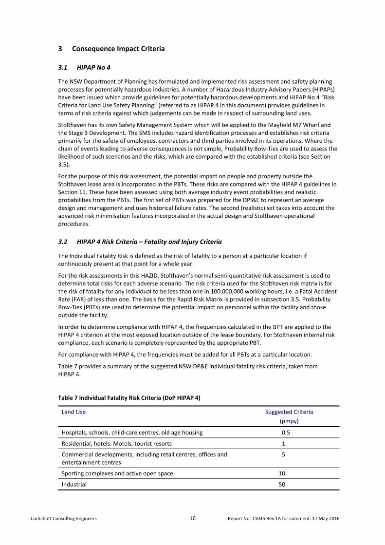
Cockshott Consulting Engineers 16 Report No: 11045 Rev 1A for comment: 17 May 2016
3 Consequence Impact Criteria
3.1 HIPAP No 4
The NSW Department of Planning has formulated and implemented risk assessment and safety planning processes for potentially hazardous industries. A number of Hazardous Industry Advisory Papers (HIPAPs) have been issued which provide guidelines for potentially hazardous developments and HIPAP No 4 “Risk Criteria for Land Use Safety Planning” (referred to as HIPAP 4 in this document) provides guidelines in terms of risk criteria against which judgements can be made in respect of surrounding land uses.
Stolthaven has its own Safety Management System which will be applied to the Mayfield M7 Wharf and the Stage 3 Development. The SMS includes hazard identification processes and establishes risk criteria primarily for the safety of employees, contractors and third parties involved in its operations. Where the chain of events leading to adverse consequences is not simple, Probability Bow‐Ties are used to assess the likelihood of such scenarios and the risks, which are compared with the established criteria (see Section 3.5).
For the purpose of this risk assessment, the potential impact on people and property outside the Stolthaven lease area is incorporated in the PBTs. These risks are compared with the HIPAP 4 guidelines in Section 11. These have been assessed using both average industry event probabilities and realistic probabilities from the PBTs. The first set of PBTs was prepared for the DPI&E to represent an average design and management and uses historical failure rates. The second (realistic) set takes into account the advanced risk minimisation features incorporated in the actual design and Stolthaven operational procedures.
3.2 HIPAP 4 Risk Criteria – Fatality and Injury Criteria
The Individual Fatality Risk is defined as the risk of fatality to a person at a particular location if continuously present at that point for a whole year.
For the risk assessments in this HAZID, Stolthaven’s normal semi‐quantitative risk assessment is used to determine total risks for each adverse scenario. The risk criteria used for the Stolthaven risk matrix is for the risk of fatality for any individual to be less than one in 100,000,000 working hours, i.e. a Fatal Accident Rate (FAR) of less than one. The basis for the Rapid Risk Matrix is provided in subsection 3.5. Probability Bow‐Ties (PBTs) are used to determine the potential impact on personnel within the facility and those outside the facility.
In order to determine compliance with HIPAP 4, the frequencies calculated in the BPT are applied to the HIPAP 4 criterion at the most exposed location outside of the lease boundary. For Stolthaven internal risk compliance, each scenario is completely represented by the appropriate PBT.
For compliance with HIPAP 4, the frequencies must be added for all PBTs at a particular location.
Table 7 provides a summary of the suggested NSW DP&E individual fatality risk criteria, taken from HIPAP 4.
Table 7 Individual Fatality Risk Criteria (DoP HIPAP 4)
Land Use Suggested Criteria
(pmpy)
Hospitals, schools, child‐care centres, old age housing 0.5
Residential, hotels. Motels, tourist resorts 1
Commercial developments, including retail centres, offices and entertainment centres
5
Sporting complexes and active open space 10
Industrial 50
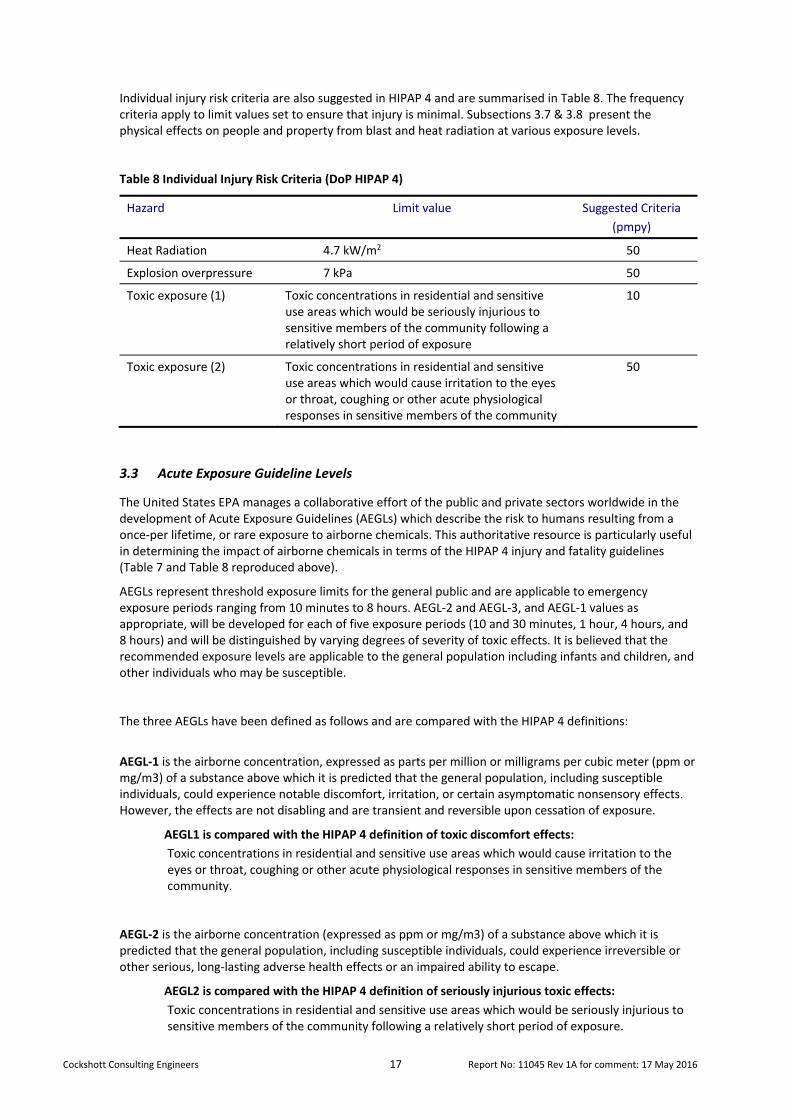
Cockshott Consulting Engineers 17 Report No: 11045 Rev 1A for comment: 17 May 2016
Individual injury risk criteria are also suggested in HIPAP 4 and are summarised in Table 8. The frequency criteria apply to limit values set to ensure that injury is minimal. Subsections 3.7 & 3.8 present the physical effects on people and property from blast and heat radiation at various exposure levels.
Table 8 Individual Injury Risk Criteria (DoP HIPAP 4)
Hazard Limit value Suggested Criteria
(pmpy)
Heat Radiation 4.7 kW/m2 50
Explosion overpressure 7 kPa 50
Toxic exposure (1)
Toxic concentrations in residential and sensitive use areas which would be seriously injurious to sensitive members of the community following a relatively short period of exposure
10
Toxic exposure (2)
Toxic concentrations in residential and sensitive use areas which would cause irritation to the eyes or throat, coughing or other acute physiological responses in sensitive members of the community
50
3.3 Acute Exposure Guideline Levels
The United States EPA manages a collaborative effort of the public and private sectors worldwide in the development of Acute Exposure Guidelines (AEGLs) which describe the risk to humans resulting from a once‐per lifetime, or rare exposure to airborne chemicals. This authoritative resource is particularly useful in determining the impact of airborne chemicals in terms of the HIPAP 4 injury and fatality guidelines (Table 7 and Table 8 reproduced above).
AEGLs represent threshold exposure limits for the general public and are applicable to emergency exposure periods ranging from 10 minutes to 8 hours. AEGL‐2 and AEGL‐3, and AEGL‐1 values as appropriate, will be developed for each of five exposure periods (10 and 30 minutes, 1 hour, 4 hours, and 8 hours) and will be distinguished by varying degrees of severity of toxic effects. It is believed that the recommended exposure levels are applicable to the general population including infants and children, and other individuals who may be susceptible.
The three AEGLs have been defined as follows and are compared with the HIPAP 4 definitions:
AEGL‐1 is the airborne concentration, expressed as parts per million or milligrams per cubic meter (ppm or mg/m3) of a substance above which it is predicted that the general population, including susceptible individuals, could experience notable discomfort, irritation, or certain asymptomatic nonsensory effects. However, the effects are not disabling and are transient and reversible upon cessation of exposure.
AEGL1 is compared with the HIPAP 4 definition of toxic discomfort effects:
Toxic concentrations in residential and sensitive use areas which would cause irritation to the eyes or throat, coughing or other acute physiological responses in sensitive members of the community.
AEGL‐2 is the airborne concentration (expressed as ppm or mg/m3) of a substance above which it is predicted that the general population, including susceptible individuals, could experience irreversible or other serious, long‐lasting adverse health effects or an impaired ability to escape.
AEGL2 is compared with the HIPAP 4 definition of seriously injurious toxic effects:
Toxic concentrations in residential and sensitive use areas which would be seriously injurious to sensitive members of the community following a relatively short period of exposure.

Cockshott Consulting Engineers 18 Report No: 11045 Rev 1A for comment: 17 May 2016
AEGL‐3 is the airborne concentration (expressed as ppm or mg/m3) of a substance above which it is predicted that the general population, including susceptible individuals, could experience life‐threatening health effects or death.
AEGL3 is taken as the exposure level at which a fatality may occur. Airborne concentrations below the AEGL‐1 represent exposure levels that can produce mild and progressively increasing but transient and non‐disabling odour, taste, and sensory irritation or certain asymptomatic, non‐sensory effects. With increasing airborne concentrations above each AEGL, there is a progressive increase in the likelihood of occurrence and the severity of effects described for each corresponding AEGL. Although the AEGL values represent threshold levels for the general public, including susceptible subpopulations, such as infants, children, the elderly, persons with asthma, and those with other illnesses, it is recognized that individuals, subject to unique or idiosyncratic responses, could experience the effects described at concentrations below the corresponding AEGL.
3.4 HIPAP 4 Environmental Impacts
For environmental impacts, HIPAP 4 defines levels of impact as a level descriptor and associated definition, as shown in Table 9.
The descriptors have been incorporated into Stolthaven’s RRR equivalent consequence levels, as defined in the table.
Table 9 Equivalence Table of Environmental Consequences (HIPAP/Stolthaven)
Consequence Type HIPAP
Stolthaven Equivalent Category
Description
Catastrophic Extreme Catastrophe
Irreversible alteration to one or more eco‐systems or several component levels. Effects can be transmitted, can accumulate. Loss of sustainability of most resources. Life cycle of species impaired. No recovery. Area affected 100 km2.
Very serious Catastrophic Alteration to one or more eco‐systems or component levels, but not irreversible. Effects can be transmitted, can accumulate. Loss of sustainability of selected resources. Recovery in 50 years. Area affected 50 km2
Serious Major Alteration/disturbance of a component of an ecosystem. Effects not transmitted, not accumulating or impairment. Loss of resources but sustainability unaffected. Recovery in 10 years.
Moderate Moderate Temporary alteration or disturbance beyond natural variability. Effects confined to <5000 m2, not accumulating or impairment. Loss of resources but sustainability unaffected. Recovery temporarily affected. Recovery < 5 years
Not detectable Minor Alteration or disturbance within natural variability. Effects not transmitted, not accumulating. Resources not impaired
3.5 Stolthaven Risk Criteria
Stolthaven uses a standardised risk method which is based on a target criterion of one fatality per 100 million working hours for the most exposed employee from all potential hazards. In order to apply this risk criterion to the calculated frequencies of fatality resulting from a single adverse event, it is necessary to make assumptions as to the exposure of the individual to that event. The following calculation makes that transformation.
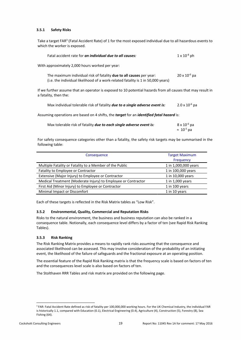
Cockshott Consulting Engineers 19 Report No: 11045 Rev 1A for comment: 17 May 2016
3.5.1 Safety Risks
Take a target FAR3 (Fatal Accident Rate) of 1 for the most exposed individual due to all hazardous events to which the worker is exposed. Fatal accident rate for an individual due to all causes: 1 x 10‐8 ph With approximately 2,000 hours worked per year: The maximum individual risk of fatality due to all causes per year: 20 x 10‐6 pa (i.e. the individual likelihood of a work‐related fatality is 1 in 50,000 years) If we further assume that an operator is exposed to 10 potential hazards from all causes that may result in a fatality, then the: Max individual tolerable risk of fatality due to a single adverse event is: 2.0 x 10‐6 pa Assuming operations are based on 4 shifts, the target for an identified fatal hazard is: Max tolerable risk of fatality due to each single adverse event is: 8 x 10‐6 pa ≈ 10‐5 pa For safety consequence categories other than a fatality, the safety risk targets may be summarised in the following table:
Consequence Target Maximum Frequency
Multiple Fatality or Fatality to a Member of the Public 1 in 1,000,000 years
Fatality to Employee or Contractor 1 in 100,000 years
Extensive (Major Injury) to Employee or Contractor 1 in 10,000 years
Medical Treatment (Moderate Injury) to Employee or Contractor 1 in 1,000 years
First Aid (Minor Injury) to Employee or Contractor 1 in 100 years
Minimal Impact or Discomfort 1 in 10 years
Each of these targets is reflected in the Risk Matrix tables as “Low Risk”.
3.5.2 Environmental, Quality, Commercial and Reputation Risks
Risks to the natural environment, the business and business reputation can also be ranked in a consequence table. Notionally, each consequence level differs by a factor of ten (see Rapid Risk Ranking Tables).
3.5.3 Risk Ranking
The Risk Ranking Matrix provides a means to rapidly rank risks assuming that the consequence and associated likelihood can be assessed. This may involve consideration of the probability of an initiating event, the likelihood of the failure of safeguards and the fractional exposure at an operating position.
The essential feature of the Rapid Risk Ranking matrix is that the frequency scale is based on factors of ten and the consequences level scale is also based on factors of ten.
The Stolthaven RRR Tables and risk matrix are provided on the following page.
3 FAR: Fatal Accident Rate defined as risk of fatality per 100,000,000 working hours. For the UK Chemical Industry, the individual FAR is historically 1.1, compared with Education (0.1), Electrical Engineering (0.4), Agriculture (4), Construction (5), Forestry (8), Sea Fishing (64).

Cockshott Consulting Engineers 20 Report No: 11045 Rev 1A for comment: 17 May 2016
RAPID RISK RANKING
LIKELIHOOD Almost certain Expected to occur in most circumstances. 10 per year
Likely Will probably occur in most circumstances. 1 per year
Moderate Should occur at some time during the plant’s operation. 1 in 10 y
Unlikely Could occur at some time during the plant’s operation. 1 in 100 y
Rare Could only occur in exceptional circumstances. 1 in 1,000 y
Extremely rare Could only occur with concurrent incidence of unlikely or rare events. 1 in 10,000 y
Barely credible The scenario is barely credible 1 in 100,000 y
Non‐credible No feasible scenario can be developed 1 in 1,000,000 y
CONSEQUENCE
Insignificant No injuries or chronic effects, discomfort, or insignificant effect on the environment or insignificant plant interruption or low financial loss $1K ($400 ‐ $3K), handled as part of normal operations
Minor First aid treatment or reversible effects or alteration or disturbance to the environment within natural variability, not accumulating, or minor plant interruption or medium financial loss $10K ($4K ‐ $30K), some resources diverted.
Moderate
Medical treatment required or non‐reversible, non‐debilitating chronic effects (e.g. sensitization) or temporary alteration or disturbance to the environment beyond natural variability (recovery < 5 years) or extended plant interruption or high financial loss $100K ($40K ‐ $300K) or, significant resources needed in response.
Major
Extensive injuries or nonreversible debilitation (e.g. asthma, hearing loss or reproductive loss) or alteration or disturbance to a component of the ecosystem. Effects not transmitted, not accumulating or impairment. Loss of resources but sustainability unaffected (recovery 10 years) or extended plant shutdown or major financial loss $1M ($400K ‐ $3M), external resources required in response.
Catastrophic
Single fatality (1 ‐3) on‐site or terminal illness or Alteration to one or more eco‐systems or component levels, but not irreversible. Effects can be transmitted, can accumulate. Loss of sustainability of selected resources (recovery in 50 years) or loss of production capability or huge financial loss $10M ($4M ‐ $30M)
Extreme Catastrophe
Multiple fatalities (4‐40) on‐site or single fatality or terminal illness offsite or Irreversible alteration to one or more eco‐systems or several component levels. Effects can be transmitted, can accumulate. Loss of sustainability of most resources. Life cycle of species impaired. No recovery or irreparable plant damage or enormous financial loss >$40M.
RISK ANALYSIS MATRIX
Likelihood
Consequences
Insig. Minor Moderate Major Catastr. Extreme Catastr.
Almost certain S S H VH VH VH
Likely M S S H VH VH
Moderate L M S S H VH
Unlikely L L M S S H
Rare N L L M S S
Extremely Rare N N L L M S
Barely credible N N N L L M
Non‐credible N N N N L L
VH: Very High Risk Unacceptable. Notify corporate management. Immediate action required.
H: High Risk Unacceptable. Notify corporate management. Immediate planning required,
S: Significant Risk Notify corporate management. Determine action plan to reduce risk.
M: Moderate Risk Evaluate alternatives to reduce risk
L: Low Risk No further action required ‐ Manage by routine procedures
N: Negligible Risk No further action required
SFAP Regardless of the likelihood, risk must be reduced So Far As Practicable

Cockshott Consulting Engineers 21 Report No: 11045 Rev 1A for comment: 17 May 2016
3.6 Probability Bow‐Ties
Stolthaven use BPTs4 to represent the chain of events from an initiation of a hazardous event through safeguards to final outcomes. The PBT incorporates the probabilities of the failure of safeguards to predict the frequency of adverse outcomes.
Whereas the primary purpose of this technique is to meet Stolthaven’s occupational health and safety and environmental guidelines, the predicted frequencies can also be used to determine offsite effect frequencies and can be used as likelihood estimates in QRA.
The advantage of PBTs is that they are transparent, providing a pictorial representation of the hazard and the assigned value of actual safeguards, with all assumptions recorded. They are most useful in operator training and as they are “owned” and maintained by Stolthaven and can readily be updated if data or circumstances change. This is in contrast to traditional QRAs, which are usually produced externally, are not transparent, represent average design and operations based on historical data and are of little value to the terminal or berth operator in risk management following their preparation.
3.7 Thermal Radiation
Table 10 presents the physical effects to assets and people resulting from exposure to heat radiation. For the purposes of modelling, heat radiation contours are developed with levels of 4.7, 12.6, 23 and 35 kW/m2.
Table 10 Effects of thermal radiation
Heat Radiation Level
(kW/m2)
Physical Effects to People & Property
35 Significant chance of fatality for people exposed instantaneously
23 100% lethality in one minute
Significant injury in 10 sec
Spontaneous ignition of wood for extended exposure
12.6 Significant chance of fatality for extended exposure. 1% lethality in one minute.
Minimum energy to ignite wood with a flame after long exposure; after long exposure, wood can be readily ignited; plastic tubing melts.
First degree burns in 10 sec
4.7 Causes pain if duration is 15‐ 20 seconds and injury (second degree burns) after 30 second exposure
2.1 Minimum to cause pain to unprotected individuals in 1 minute
Source: SFPE Handbook of Fire Protection (Third Edition) Table 5‐13.3 & HIPAP No 4.
3.8 Blast Effects
Table 11 overleaf presents the physical effects to assets and people resulting from an explosion overpressure. For the purposes of modelling, overpressure contours are developed with levels of 3.5, 7, 17, 35 and 80 kPa.
4 Probability Bow–Ties A Transparent Risk Management Tool, J E Cockshott, Trans IChemE, Part B, July 2005, Process Safety and Environmental Protection, 83(B4):307‐316
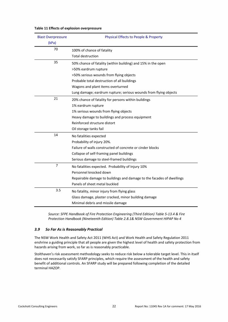
Cockshott Consulting Engineers 22 Report No: 11045 Rev 1A for comment: 17 May 2016
Table 11 Effects of explosion overpressure
Blast Overpressure
(kPa)
Physical Effects to People & Property
70 100% of chance of fatality
Total destruction
35 50% chance of fatality (within building) and 15% in the open
>50% eardrum rupture
>50% serious wounds from flying objects
Probable total destruction of all buildings
Wagons and plant items overturned
Lung damage; eardrum rupture; serious wounds from flying objects
21 20% chance of fatality for persons within buildings
1% eardrum rupture
1% serious wounds from flying objects
Heavy damage to buildings and process equipment
Reinforced structure distort
Oil storage tanks fail
14 No fatalities expected
Probability of injury 20%.
Failure of walls constructed of concrete or cinder blocks
Collapse of self‐framing panel buildings
Serious damage to steel‐framed buildings
7 No fatalities expected. Probability of Injury 10%
Personnel knocked down
Repairable damage to buildings and damage to the facades of dwellings
Panels of sheet metal buckled
3.5 No fatality, minor injury from flying glass
Glass damage, plaster cracked, minor building damage
Minimal debris and missile damage
Source: SFPE Handbook of Fire Protection Engineering (Third Edition) Table 5‐13.4 & Fire Protection Handbook (Nineteenth Edition) Table 2.8.1& NSW Government HIPAP No 4
3.9 So Far As is Reasonably Practical
The NSW Work Health and Safety Act 2011 (WHS Act) and Work Health and Safety Regulation 2011 enshrine a guiding principle that all people are given the highest level of health and safety protection from hazards arising from work, so far as is reasonably practicable.
Stolthaven’s risk assessment methodology seeks to reduce risk below a tolerable target level. This in itself does not necessarily satisfy SFARP principles, which require the assessment of the health and safety benefit of additional controls. An SFARP study will be prepared following completion of the detailed terminal HAZOP.
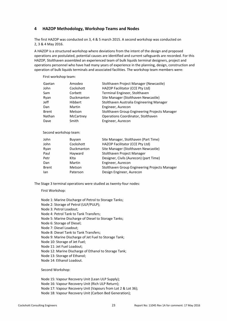
Cockshott Consulting Engineers 23 Report No: 11045 Rev 1A for comment: 17 May 2016
4 HAZOP Methodology, Workshop Teams and Nodes
The first HAZOP was conducted on 3, 4 & 5 march 2015. A second workshop was conducted on 2, 3 & 4 May 2016.
A HAZOP is a structured workshop where deviations from the intent of the design and proposed operations are postulated, potential causes are identified and current safeguards are recorded. For this HAZOP, Stolthaven assembled an experienced team of bulk liquids terminal designers, project and operations personnel who have had many years of experience in the planning, design, construction and operation of bulk liquids terminals and associated facilities. The workshop team members were:
First workshop team:
Gaetan Amodeo Stolthaven Project Manager (Newcastle) John Cockshott HAZOP Facilitator (CCE Pty Ltd)Sam Corbett Terminal Engineer, StolthavenRyan Duckmanton Site Manager (Stolthaven Newcastle)Jeff Hibbert Stolthaven Australia Engineering Manager Dan Martin Engineer, AureconBrent Metson Stolthaven Group Engineering Projects Manager Nathan McCartney Operations Coordinator, Stolthaven Dave Smith Engineer, Aurecon
Second workshop team:
John Buysen Site Manager, Stolthaven (Part Time)John Cockshott HAZOP Facilitator (CCE Pty Ltd)Ryan Duckmanton Site Manager (Stolthaven Newcastle)Paul Hayward Stolthaven Project ManagerPetr KIta Designer, Civils (Aurecon) (part Time)Dan Martin Engineer, AureconBrent Metson Stolthaven Group Engineering Projects Manager Ian Paterson Design Engineer, Aurecon
The Stage 3 terminal operations were studied as twenty‐four nodes:
First Workshop: Node 1: Marine Discharge of Petrol to Storage Tanks; Node 2: Storage of Petrol (ULP/PULP); Node 3: Petrol Loadout; Node 4: Petrol Tank to Tank Transfers; Node 5: Marine Discharge of Diesel to Storage Tanks; Node 6: Storage of Diesel; Node 7: Diesel Loadout; Node 8: Diesel Tank to Tank Transfers; Node 9: Marine Discharge of Jet Fuel to Storage Tank; Node 10: Storage of Jet Fuel; Node 11: Jet Fuel Loadout; Node 12: Marine Discharge of Ethanol to Storage Tank; Node 13: Storage of Ethanol; Node 14: Ethanol Loadout. Second Workshop: Node 15: Vapour Recovery Unit (Lean ULP Supply); Node 16: Vapour Recovery Unit (Rich ULP Return); Node 17: Vapour Recovery Unit (Vapours from Lot 2 & Lot 36); Node 18: Vapour Recovery Unit (Carbon Bed Generation);

Cockshott Consulting Engineers 24 Report No: 11045 Rev 1A for comment: 17 May 2016
Node 19: Biodiesel and Additive Tanks (load‐in from trucks IBC or isotainers); Node 20: Biodiesel and Additive Tanks (Tank); Node 21: Biodiesel and Additive Tanks (Loadout); Node 22: Drainage System Option 1 (Gravity Drainage); Node 23: Drainage System Option 2 (Pumpout); Node 24: Slops System (Slops Receival); Node 25: Slops System (Slops Disposal).
The team applied the following guidewords to each node:
NONE
MORE
LESS
DIFFERENT
OTHER
OHS & Environmental guide phrases
The potential consequence(s) of each adverse event was discussed and recorded as well as experienced estimates made for the probability of failure‐on‐demand (PFD) of the safeguards. Requirements for further analysis of consequences and risk were also identified.
As an integral part of the first workshop, a previous HAZID Study (Report 11039) for the preliminary design of the berth and a previous HAZID Study (Report 11043) for the preliminary design of the terminal for Stage 3 were reviewed.
The HAZOP Report No: 11045 Rev 1 draft therefore represents a consolidation of all previous process hazard analysis studies for the Newcastle Terminal.

Cockshott Consulting Engineers 25 Report No: 11045 Rev 1A for comment: 17 May 2016
5 HAZOP Notes (3, 4 & 5 March 2015)
HAZOP Notes Client: Stolthaven Australia Pty Ltd Sheet 1 of 57
Report No 11045 Rev 0: 15/10/2015 Project: Stage 3 Development HAZOP Date: 3, 4 & 5 March 2015
GUIDEWORD/
DEVIATION
Cause of Deviation
Consequence
RRR analysis
Safeguards
Action/notes/
Residual Risk
© 2016 Cockshott Consulting Engineers Pty Ltd
Node 1: Marine Discharge of Petrol to Storage Tanks (PFD: 236974‐0000‐DRG‐PFD‐001‐C; P&IDs: 236974‐0000‐DRG‐PID‐101‐B, ‐102‐B & 011‐B [typical tank])
Petrol will be discharged by the ship’s pumps (max 10 Bar), with the ship’s manifold bolted to a spool connected to the carbon steel Marine Loading Arm (MLA). The shore connection of the MLA is permanently bolted to the wharf line. Two MLAs will be installed for diesel fuel and petrol. The wharf line configuration comprises a header connected to both petrol and diesel wharf lines with two 400 mm dia carbon steel petrol lines (and two 400mm carbon steel diesel lines – Node 5). The wharf lines run aboveground and over the walkway & northern access road. This provides continuous visual contact with the wharf line.
Acceptance of a vessel to the berth commences with ship notification, completion of Q88 and acceptance by PANSW and the terminal
Prior to the ship’s arrival, the terminal checks tank & pipeline valving, communications equipment, pipeline and MLA (pressure tests), firefighting equipment, first aid equipment, fittings and adapters, spill control equipment, lifting gear and tank gauging equipment.
On arrival, a discharge plan is agreed between the ship and terminal.
The MLA is connected and a pressure test conducted up to 7 bar with nitrogen to ensure the integrity of the MLA, bolted connections and manifold isolation valves.
Personnel involved in the discharge operation include:
One terminal operator at the wharf manifold
One ship’s crew at the ship’s manifold
One terminal operator as line‐walker
One terminal control room operator
Ship’s officer in the ship’s control room
Third party surveyor
All communication is made by intrinsically safe (IS) hand‐held radio or IS mobile phone.
With the wharf line lined‐up to the receiving tank, the terminal will instruct the ship to start slow pumping. This is to ensure that there is no leakage and that the entry pipe into the receiving tank is covered. When the terminal is ready and the pipeline checked, the ship’s officer will be requested to increase the pump pressure until the maximum discharge rate is achieved. Communications are maintained continuously and pumping is stopped in the event of loss of communication. Ship and shore tank levels are monitored continually and are recorded each hour to confirm rates and estimated time of completion. The terminal will request a reduction of rate towards the end of parcel discharge or on changing shore tanks. If the ship is stripping the cargo tank, the ship will slow down the transfer to empty the tank.
The ship’s manifold and wharf manifold isolating valves are closed on completion of the transfer.
Either pig station can be connected to individual yard lines serving each storage tank:
7 x 300mm yard lines to Tanks 10‐16 (maximum length ~220m);
3 x 350mm yard lines to Tanks 17‐19 (maximum length ~260m).
All petrol ranks are internal floating roof tanks.

HAZOP Notes Client: Stolthaven Australia Pty Ltd Sheet 2 of 57
Report No 11045 Rev 0: 15/10/2015 Project: Stage 3 Development HAZOP Date: 3, 4 & 5 March 2015
GUIDEWORD/
DEVIATION
Cause of Deviation
Consequence
RRR analysis
Safeguards
Action/notes/
Residual Risk
© 2016 Cockshott Consulting Engineers Pty Ltd
The MLA will be cleared by blowing with nitrogen from the ships manifold through to the shore connection.
Nitrogen will be used to pig the line from the wharf pig launcher to the terminal pig receiver.
The wharf line is then depressurised and will rest on nitrogen pending the next discharge. An isolation valve will be provided shore‐side on the petrol lines.
Both petrol and diesel could be discharged at the same time.
During discharge, weather conditions are monitored against PANSW environmental protocols and pumping is stopped and the MLA may be disconnected according to conditions. The PANSW may also require discharge to be stopped for passing ships.
Wharf firefighting equipment will be provided in accordance with ISGOTT and AS3846.
1.1 Marine Discharge to Petrol Tanks MORE
Static electricity ‐ ignition in wharf lines.
Flammable/Explosive materials:
ULP/ PULP.
Residual vapour in wharf line from the berth to the terminal, following discharge and pigging with nitrogen.
Sources of Ignition:
High velocity in wharf and yard lines leading to static generation.
Lightning.
Static generation:
Pipe velocities based on 1500m3/h:
MLA 12” 300mm 5.8 Wharf 400mm: 3.7 m/s Yard 350mm: 6.0 m/s Yard 300mm: 4.8 m/s
For non‐conductive liquids, the following velocity limits should be applied (AS 1020):
400mm: 1.3 m/s 350mm: 1.4 m/s 300mm: 1.5 m/s
Given the use of nitrogen for clearing lines, ignition was considered non‐credible:
Current Risk:
N Cred x Maj = Neg Risk (S)
All wharf and yard piping is electrically earthed and fully contained (no lightning hazard).
Petrol generally has a conductivity >50pS/m and is considered as a conductive liquid.
(API RP2003 data: Petrol 10‐3,000pS/m with a relaxation time of 1.8 to 0.0006 sec).
Stadis will be added at the terminal manifold.
Slow initial pumping rate with ramp‐up and ramp‐down.
Nitrogen will be used for line clearing following discharge, therefore there is no possibility of a flammable mixture in the piping.
No action.
Residual Risk:
N Cred x Maj = Neg Risk (S)
HAZOP Notes Client: Stolthaven Australia Pty Ltd Sheet 3 of 57
Report No 11045 Rev 0: 15/10/2015 Project: Stage 3 Development HAZOP Date: 3, 4 & 5 March 2015
GUIDEWORD/
DEVIATION
Cause of Deviation
Consequence
RRR analysis
Safeguards
Action/notes/
Residual Risk
© 2016 Cockshott Consulting Engineers Pty Ltd
1.2 Marine Discharge to Petrol Tanks MORE Static electricity ‐ ignition in Petrol Tanks.
Flammable/Explosive materials:
ULP/ PULP.
Flammable vapour in the storage tank before the roof is afloat.
Sources of Ignition:
Static generation during discharge.
Potential for ignition of the air/petrol vapour below the internal floating roof when this is landed.
With the inherently high conductivity of ULP/PULP, ignition is extremely unlikely.
With normal procedural controls (particularly on initial fill when the roof is landed) the likelihood is further reduced.
A fire/explosion in a virtually empty IFR tank could cause a fatality to personnel present (though occupancy needs to be taken into account ‐ <10% at tank).
Given the use of nitrogen for clearing lines and precautions taken on initial tank filling, ignition was considered barely credible:
Current Risk:
B Cred x Cat = Low Risk (S)
All storage tanks and internal floating roofs are earthed.
Bottom filling with diffuser.
Procedural control (slow initial filling) to drive air from under the floating roof (NFPA 77 recommendation is <1m/s for low conductivity fluids until the roof is afloat, then no maximum velocity requirement).
Petrol generally has a conductivity >50pS/m and is considered as a conductive liquid.
(API RP2003 data: Gasoline 10‐3,000pS/m with a relaxation time of 1.8 to 0.0006 sec).
Stadis will be added at the terminal manifold.
All customers dose petrol products to increase conductivity.
Proceduralise petrol discharge to ensure that the NFPA77 recommendations are observed with landed floating roof and that the maximum velocity does not exceed 7 m/s.
Residual Risk:
N Cred x Cat = Low Risk (S)
PBT B.10 Risk: Low Risk (S)
1.3 Marine Discharge to Petrol Tanks MORE Heat radiation from a gantry fire.
Fire in southern gantry adjacent to petrol storage tanks.
The intensity and duration of a gantry fire is unlikely to impact on neighbouring tanks and will be determined by consequence analysis.
Scully overfill protection & earthing.
Maximum fill size 10,000L.
Remote Impounding basin for spills.
Electrical hazardous area classification and exclusion of ignition sources.
Gantry fire detection.
Gantry foam application.
Determine gantry fire knock‐on to neighbouring tanks in consequence analysis and in PBTs.
HAZOP Notes Client: Stolthaven Australia Pty Ltd Sheet 4 of 57
Report No 11045 Rev 0: 15/10/2015 Project: Stage 3 Development HAZOP Date: 3, 4 & 5 March 2015
GUIDEWORD/
DEVIATION
Cause of Deviation
Consequence
RRR analysis
Safeguards
Action/notes/
Residual Risk
© 2016 Cockshott Consulting Engineers Pty Ltd
1.4 Marine Discharge to Petrol Tanks MORE Heat radiation from a gantry fire.
Fire in adjacent gantry. The intensity and duration of a gantry fire is unlikely to impact on neighbouring tanks and will be determined by consequence analysis.
Scully overfill protection & earthing.
Maximum fill size 10,000L.
Remote Impounding basin for spills.
Electrical hazardous area classification and exclusion of ignition sources.
Gantry fire detection.
Gantry foam application (stops discharge).
Site ESD: stops discharge.
Determine gantry fire knock‐on to neighbouring tanks in consequence analysis and in PBTs.
1.5 Marine Discharge to Petrol Tanks MORE LOSS OF CONTAINMENT Pipeline leakage.
Solar Radiation.
Deterioration of gaskets.
Flanges not bolted tightly.
Heating and expansion of contained flammable liquid (but wharf lines will rest on nitrogen).
Small leakage of flammable liquid at flanges.
Safeguards considered adequate.
The pipeline is walked in the initial stages of discharge and regularly throughout discharge.
Thermal relief is provided (to the tank) as part of the detailed design.
Flanges will be at contained areas.
Operational areas at the wharf and pig receival manifold are bunded.
Drip trays for maintenance operations.
Wharf lines rest on nitrogen between discharges.
No action.

HAZOP Notes Client: Stolthaven Australia Pty Ltd Sheet 5 of 57
Report No 11045 Rev 0: 15/10/2015 Project: Stage 3 Development HAZOP Date: 3, 4 & 5 March 2015
GUIDEWORD/
DEVIATION
Cause of Deviation
Consequence
RRR analysis
Safeguards
Action/notes/
Residual Risk
© 2016 Cockshott Consulting Engineers Pty Ltd
1.6 Marine Discharge to Petrol Tanks MORE LOSS OF CONTAINMENT Storage Tank Overfill.
Marine discharge ‐ filling beyond safe fill.
Ullage error.
Procedure error at SFL.
Procedural error during switch filling.
Overfill of flammable ULP/PULP to the bunded area.
Potential ignition and bund fire.
Damage to foam pourers.
Damage to floating roof.
Considered possible 1 in 10 years (considering 12 tanks with ~30 fills per year).
PFD of response to LAH was considered as 1:100 (focussed task).
Probability of ignition 1:100.
Current Risk without LSHH interlock:
1/10 yr x 1/100 x 1/100= 1/100,000 yr
B Cred x Maj = Low Risk (S & E)
Pre‐discharge planning.
Monitoring of discharge in the control room.
Level indication and LAH.
Independent LSHH on each tank is interlocked to shut the tank inlet valves.
Secondary containment – bund with internal nib walls (600mm or half height of bund wall AS1940) to limit the spread of a minor spill.
Hazardous area classification.
Control of ignition sources.
Ensure that the high‐high level switch will operate regardless of any failure of the floating roof. The system should be equivalent to SIL2 (PFD = 1:100). To be reviewed with PBTs.
Residual Risk:
Likelihood 1 in 10,000,000 yr
N Cred x Maj = Neg Risk (S & E)
PBT B.6: 9.7 10‐6 efpa (Low)
1.7 Marine Discharge to Petrol Tanks MORE High pressure ‐ surge
Tank valve slammed shut (ESD).
Ships pumps are stopped.
Manual valves closed.
Emergency release from loading arm coupling.
Potential surge pressures caused by sudden shutoff of downstream (hydraulic hammer) or upstream valve (which results in a pocket of vapour and a reverse surge as it collapses).
Loss of containment of minor quantity of flammable material.
All automated valves will close over a period determined by surge modelling.
Manual valves will take about a minute to fully close.
The design pressure of piping is 19.6bar.
For all Stage 3 tanks:
a) Review physical protection of ESD buttons to avoid inadvertent closure of tank inlet valves.
b) Review the type of valve used for tank inlet and outlet valves and the actuators for reliable operation.
c) Review the quality of instrument air used for the actuators and provide a filter/ lubricator at each actuator.
d) Include closure of tank inlet valves and stopping of ship’s pump in the proposed surge study.
HAZOP Notes Client: Stolthaven Australia Pty Ltd Sheet 6 of 57
Report No 11045 Rev 0: 15/10/2015 Project: Stage 3 Development HAZOP Date: 3, 4 & 5 March 2015
GUIDEWORD/
DEVIATION
Cause of Deviation
Consequence
RRR analysis
Safeguards
Action/notes/
Residual Risk
© 2016 Cockshott Consulting Engineers Pty Ltd
1.8 Marine Discharge to Petrol Tanks MORE Overpressure from ammonium nitrate explosion in port or heat radiation from coal carrier at berth in the channel.
Combustible/Explosive materials:
K2 Berth: bulk ammonium nitrate (2 km).
M4 Berth: packaged ammonium nitrate (1 km).
Coal Bulk Carriers (200m from M7).
Sources of Ignition:
On‐board fire on ammonium nitrate ship at K2;
Contamination of ammonium nitrate with organic materials;
Coal fire in Coal bulk carrier hold.
Blast impact from bulk or packaged ammonium nitrate explosion.
Based on the results of consequence analysis, the impact of an ammonium nitrate explosion at K2 to personnel and assets at M7 was considered to be minor.
Based on the results of consequence analysis, the impact of a bulk coal carrier fire across the channel to personnel and assets at M7 or the terminal was considered to be insignificant.
A knock‐on scenario involving release of petrol was considered non‐credible.
Current Risk:
E Rare x Min = Neg Risk (S)
External event which is not controlled by Stolthaven.
a) Operations should be halted for any event at the Ammonium Nitrate manufacturing facility (e.g. fire or ammonia release) or cargo fire on a bulk coal carrier.
Residual Risk:
E Rare x Min = Neg Risk (S)
1.9 Marine Discharge to Petrol Tanks MORE Heat radiation at the wharf from a tank fire at the Terminal.
Fire at the Newcastle Bulk Liquids Terminal.
No development of Lot 1 is included in the Stage 3 Development.
Tank top fire with heat radiation effects.
Based on the results of consequence analysis of a fire in Lot 36, a tank‐top fire has no impact to personnel or wharf assets.
Terminal fire detection and protection in accordance with the Fire Safety Study and AS1940.
Terminal Hot Work Permit procedures, exclusion of ignition sources and compliance with Hazardous Area Classification.
No action.
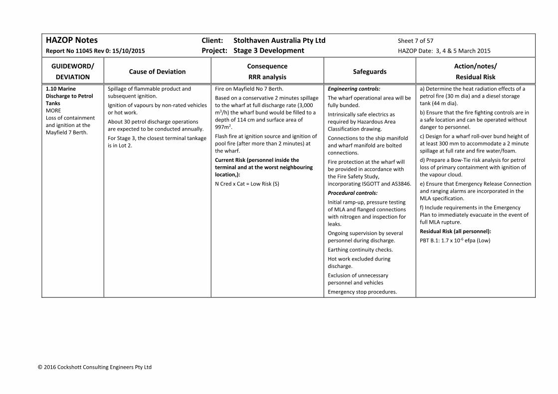
HAZOP Notes Client: Stolthaven Australia Pty Ltd Sheet 7 of 57
Report No 11045 Rev 0: 15/10/2015 Project: Stage 3 Development HAZOP Date: 3, 4 & 5 March 2015
GUIDEWORD/
DEVIATION
Cause of Deviation
Consequence
RRR analysis
Safeguards
Action/notes/
Residual Risk
© 2016 Cockshott Consulting Engineers Pty Ltd
1.10 Marine Discharge to Petrol Tanks MORE Loss of containment and ignition at the Mayfield 7 Berth.
Spillage of flammable product and subsequent ignition.
Ignition of vapours by non‐rated vehicles or hot work.
About 30 petrol discharge operations are expected to be conducted annually.
For Stage 3, the closest terminal tankage is in Lot 2.
Fire on Mayfield No 7 Berth.
Based on a conservative 2 minutes spillage to the wharf at full discharge rate (3,000 m3/h) the wharf bund would be filled to a depth of 114 cm and surface area of 997m2.
Flash fire at ignition source and ignition of pool fire (after more than 2 minutes) at the wharf.
Current Risk (personnel inside the terminal and at the worst neighbouring location,):
N Cred x Cat = Low Risk (S)
Engineering controls:
The wharf operational area will be fully bunded.
Intrinsically safe electrics as required by Hazardous Area Classification drawing.
Connections to the ship manifold and wharf manifold are bolted connections.
Fire protection at the wharf will be provided in accordance with the Fire Safety Study, incorporating ISGOTT and AS3846.
Procedural controls:
Initial ramp‐up, pressure testing of MLA and flanged connections with nitrogen and inspection for leaks.
Ongoing supervision by several personnel during discharge.
Earthing continuity checks.
Hot work excluded during discharge.
Exclusion of unnecessary personnel and vehicles
Emergency stop procedures.
a) Determine the heat radiation effects of a petrol fire (30 m dia) and a diesel storage tank (44 m dia).
b) Ensure that the fire fighting controls are in a safe location and can be operated without danger to personnel.
c) Design for a wharf roll‐over bund height of at least 300 mm to accommodate a 2 minute spillage at full rate and fire water/foam.
d) Prepare a Bow‐Tie risk analysis for petrol loss of primary containment with ignition of the vapour cloud.
e) Ensure that Emergency Release Connection and ranging alarms are incorporated in the MLA specification.
f) Include requirements in the Emergency Plan to immediately evacuate in the event of full MLA rupture.
Residual Risk (all personnel):
PBT B.1: 1.7 x 10‐6 efpa (Low)

HAZOP Notes Client: Stolthaven Australia Pty Ltd Sheet 8 of 57
Report No 11045 Rev 0: 15/10/2015 Project: Stage 3 Development HAZOP Date: 3, 4 & 5 March 2015
GUIDEWORD/
DEVIATION
Cause of Deviation
Consequence
RRR analysis
Safeguards
Action/notes/
Residual Risk
© 2016 Cockshott Consulting Engineers Pty Ltd
1.11 Marine Discharge to Petrol Tanks MORE Loss of containment at the Mayfield 7 Berth
Ship movement and rupture of MLAs.
Approximately 30 petrol discharge operations are anticipated annually.
For Stage 3, the closest terminal tankage is in Lot 2.
HAZID Note 2.3 deals with ignition events.
Secondary containment of ~100m3 of petrol (major spill) and 1m3 (minor spill).
Potential inadvertent release to the marine environment.
See petrol PBT
Current Risk:
B Cred x Mod = Neg Risk (E)
Engineering controls:
The wharf operational area will be fully bunded Full containment volume on the wharf (30 cm bund height compared with 12cm required for 2 minute spill).
Connections to the ship manifold and wharf manifold are bolted connections.
Procedural controls:
Annual pressure testing of hoses in accordance with manufacturers’ and regulatory requirements.
Initial ramp‐up, pressure testing of MLA and flanged connections with nitrogen and inspection for leaks.
Ongoing supervision by several personnel during discharge.
Earthing continuity checks.
Hot work excluded during discharge.
Exclusion of unnecessary personnel and vehicles
Emergency stop procedures.
Stand‐by booms will be provided in the event of overboard release.
a) Include in the Response Plan for the immediate application of foam to the wharf and timely removal of ~72 tonnes of spilled petrol product.
b) Provide a valved line from the interceptor to the shore for wharf spill pumpout.
c) Provide a non‐return valve on the wharf line to each storage tank.
Residual Risk:
B Cred x Mod = Neg Risk (E)

HAZOP Notes Client: Stolthaven Australia Pty Ltd Sheet 9 of 57
Report No 11045 Rev 0: 15/10/2015 Project: Stage 3 Development HAZOP Date: 3, 4 & 5 March 2015
GUIDEWORD/
DEVIATION
Cause of Deviation
Consequence
RRR analysis
Safeguards
Action/notes/
Residual Risk
© 2016 Cockshott Consulting Engineers Pty Ltd
1.12 Marine Discharge to Petrol Tanks MORE High kinetic energy
High winds.
Passing ships.
Potential for MLA disconnection.
Risks are covered in Notes 1.10 & 1.11 (incorporated in loading arm failure rates).
The bulk liquid carrier is loaded in accordance with the IMDG Code, providing separation of non‐compatible cargoes.
Vessels are double‐hulled in accordance with Marpol 1 & 2, preventing external damage (e.g. on berthing) with release of fuels.
Port of Newcastle Ship Handling Safety Guidelines.
A mooring Study and a Ship Interaction Study will be performed to determine final mooring requirements and impacts.
No action.
1.13 Marine Discharge to Petrol Tanks DIFFERENT Cross‐contamination at wharf and at tank manifold.
Potential cross contamination from wharf manifold to wharf lines (diesel and petrol)
Possible cross contamination from tank manifold to yard lines.
With compatible products on both of the tank manifold valves and with the tank inlet valves closed, contamination is not an issue for the tank manifold.
Possible cross contamination of diesel/petrol grades is possible at the wharf and appropriate isolation is required.
Double block & cavity valves are shown on the P&IDs.
a) For the wharf manifold, review the options of:
Spectacle blind and gate valve;
Double block & cavity valve
Double gate valves and bleed
b) For the tank manifold, replace the double block and cavity valves with gate valves.
1.14 Marine Discharge to Petrol Tanks OTHER Vehicle impact.
Impact of vehicles with pipeline structural supports.
Pipeline rupture.
Loss of containment to the marine or soil environment.
Safeguards considered adequate.
Site security (gatehouse). The gatehouse will be manned during discharge.
Protection of structural supports.
The pipebridge towers will be placed to avoid proximity to traffic.
The pipelines over the pipebridge will not rest on product.
No action.

HAZOP Notes Client: Stolthaven Australia Pty Ltd Sheet 10 of 57
Report No 11045 Rev 0: 15/10/2015 Project: Stage 3 Development HAZOP Date: 3, 4 & 5 March 2015
GUIDEWORD/
DEVIATION
Cause of Deviation
Consequence
RRR analysis
Safeguards
Action/notes/
Residual Risk
© 2016 Cockshott Consulting Engineers Pty Ltd
1.15 Marine Discharge to Petrol Tanks OTHER Vehicle impact during Koppers discharge operations.
Koppers will require access for line walks during discharge of their products.
Potential vehicle impacts with terminal infrastructure if access is provided for vehicles along the pipeline.
Fire access will be maintained.
Protection of structural supports.
The pipebridge towers will be placed to avoid proximity to traffic.
The pipelines over the pipebridge will not rest on product.
Provide fenced pedestrian access to the Koppers’ pipeline corridor.
1.16 Marine Discharge to Petrol Tanks OTHER Collapse of internal floating roof.
Failure of fixed roof support columns leading to unbalanced floating, corrosion, failure of various gaskets, etc.
The tank would require draining, inspection and repair before returning to service.
High level of vapour loss to the atmosphere through the air scoops.
Initial fill procedures.
Tank inspections.
Review with tank fabricators how potential IFR failures can be detected.
1.17 Marine Discharge to Petrol Tanks OHS&E Ergonomics & exposure. Environmental – loss of containment.
Operation of the pig launcher receivers – opening/closing and manhandling of the pigs.
Potential lifting and strain injuries.
Pocket of product behind the pig during pig removal – exposure and loss of containment.
Stolthaven has a standard pig receiver/launcher design which addresses ergonomic and drainage issues.
a) Stolthaven to provide parameters for the pig launchers and receivers (all products)
b) The pig launcher/receiver is to slope away from the door and a drain valve provided at the low point. A drip tray is to be provided at all pig launchers and receivers.
1.18 Marine Discharge to Petrol Tanks OHS&E Exposure during IFR roof inspection.
Inspections of floating roofs. Potential exposure of operators or potential ignition of roof space vapours in the event of a sunken floating roof.
Torches, meters, etc will be nominated as intrinsically safe.
The vapour in the roof space of IFR tanks should be well below LEL during normal operation of the roof.
a) Ensure that entry of an operator’s head is prevented by an arrangement of bars or mesh at the air scoops.
b) Determine procedures for ensuring that the vapours at the scoops are not hazardous (low oxygen, LEL and VOC metering included as part of the procedure).
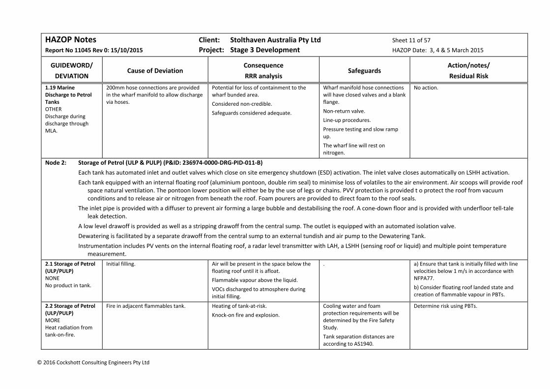
HAZOP Notes Client: Stolthaven Australia Pty Ltd Sheet 11 of 57
Report No 11045 Rev 0: 15/10/2015 Project: Stage 3 Development HAZOP Date: 3, 4 & 5 March 2015
GUIDEWORD/
DEVIATION
Cause of Deviation
Consequence
RRR analysis
Safeguards
Action/notes/
Residual Risk
© 2016 Cockshott Consulting Engineers Pty Ltd
1.19 Marine Discharge to Petrol Tanks OTHER Discharge during discharge through MLA.
200mm hose connections are provided in the wharf manifold to allow discharge via hoses.
Potential for loss of containment to the wharf bunded area.
Considered non‐credible.
Safeguards considered adequate.
Wharf manifold hose connections will have closed valves and a blank flange.
Non‐return valve.
Line‐up procedures.
Pressure testing and slow ramp up.
The wharf line will rest on nitrogen.
No action.
Node 2: Storage of Petrol (ULP & PULP) (P&ID: 236974‐0000‐DRG‐PID‐011‐B)
Each tank has automated inlet and outlet valves which close on site emergency shutdown (ESD) activation. The inlet valve closes automatically on LSHH activation.
Each tank equipped with an internal floating roof (aluminium pontoon, double rim seal) to minimise loss of volatiles to the air environment. Air scoops will provide roof space natural ventilation. The pontoon lower position will either be by the use of legs or chains. PVV protection is provided t o protect the roof from vacuum conditions and to release air or nitrogen from beneath the roof. Foam pourers are provided to direct foam to the roof seals.
The inlet pipe is provided with a diffuser to prevent air forming a large bubble and destabilising the roof. A cone‐down floor and is provided with underfloor tell‐tale leak detection.
A low level drawoff is provided as well as a stripping drawoff from the central sump. The outlet is equipped with an automated isolation valve.
Dewatering is facilitated by a separate drawoff from the central sump to an external tundish and air pump to the Dewatering Tank.
Instrumentation includes PV vents on the internal floating roof, a radar level transmitter with LAH, a LSHH (sensing roof or liquid) and multiple point temperature measurement.
2.1 Storage of Petrol (ULP/PULP) NONE No product in tank.
Initial filling. Air will be present in the space below the floating roof until it is afloat.
Flammable vapour above the liquid.
VOCs discharged to atmosphere during initial filling.
. a) Ensure that tank is initially filled with line velocities below 1 m/s in accordance with NFPA77.
b) Consider floating roof landed state and creation of flammable vapour in PBTs.
2.2 Storage of Petrol (ULP/PULP) MORE Heat radiation from tank‐on‐fire.
Fire in adjacent flammables tank. Heating of tank‐at‐risk.
Knock‐on fire and explosion.
Cooling water and foam protection requirements will be determined by the Fire Safety Study.
Tank separation distances are according to AS1940.
Determine risk using PBTs.

HAZOP Notes Client: Stolthaven Australia Pty Ltd Sheet 12 of 57
Report No 11045 Rev 0: 15/10/2015 Project: Stage 3 Development HAZOP Date: 3, 4 & 5 March 2015
GUIDEWORD/
DEVIATION
Cause of Deviation
Consequence
RRR analysis
Safeguards
Action/notes/
Residual Risk
© 2016 Cockshott Consulting Engineers Pty Ltd
2.2 Storage of Petrol (ULP/PULP) MORE Heat radiation from VRU.
Loss of containment and fire at VRU. Potential impact to flammables tanks. Ensure that VRU fire is modelled in PBTs and QRA.
2.3 Storage of Petrol (ULP/PULP) MORE LOSS OF CONTAINMENT Tank breathing.
Discharge of flammable vapours from the vented shell.
It is anticipated that vapour discharge to atmosphere will be low due to the use of internal floating roof tanks.
The flammables tanks are equipped with internal floating roofs to minimise loss to the environment.
Review emissions rates for IFR/cone roof tanks.
2.4 Storage of Petrol (ULP/PULP) MORE LOSS OF CONTAINMENT Overspill during watering.
Operator diversion during dewatering operations.
Discharge of product into the bunded area.
Potential for a flammable liquid pool around the dewatering outlet.
Dewatering is a manual operation and procedures will require continuous attendance during dewatering operations.
A dead‐man handle is provided on the tank dewatering valve.
Secondary containment provided by impermeable bunds.
Electrical hazardous area zoning.
Exclusion of ignition sources.
No action.
2.5 Storage of Petrol (ULP/PULP) MORE LOSS OF CONTAINMENT Inadvertent tank to tank transfer.
Common liquid lines open to truck filling.
Potential for height differences to allow gravity transfer (final tank heights have not yet been determined).
With overfill protection, safeguards considered adequate.
Overfill protection is provided on all flammables tanks (LAHH interlocked to inlet actuated valves).
Check valves are provided on all tank outlets.
Stripping line valve is locked closed.
No action.
2.6 Storage of Petrol (ULP/PULP) MORE Foam introduced to tank.
Inadvertent introduction of foam.
Deliberate foam application.
Safeguards preventing inadvertent activation were considered adequate.
In the event of an emergency, then foam application will preserve fixed assets but could result in product loss.
The foam system has a dry riser to the pourer and a witness hole.
No action.

HAZOP Notes Client: Stolthaven Australia Pty Ltd Sheet 13 of 57
Report No 11045 Rev 0: 15/10/2015 Project: Stage 3 Development HAZOP Date: 3, 4 & 5 March 2015
GUIDEWORD/
DEVIATION
Cause of Deviation
Consequence
RRR analysis
Safeguards
Action/notes/
Residual Risk
© 2016 Cockshott Consulting Engineers Pty Ltd
2.7 Storage of Petrol (ULP/PULP) MORE Static electricity.
Lightning Safeguards considered adequate. Tanks are earthed and the floating roof is bonded to the shell.
The vapour space above the floating roof will be below the flammable limit.
The main roof and shell acts as a Faradays’ cage (compared with external floating roof tanks).
No action.
2.8 Storage of Petrol (ULP/PULP) MORE Nitrogen introduction to tank.
Depressurising wharf line to the tank. Introduction of nitrogen to the space below the floating roof.
Discharge of VOCs to atmosphere through the PVV.
The worst case scenario is that the PVVs cannot handle the volume of nitrogen and the internal floating roof tips and sinks.
This would require emptying of the tank, air freeing and repair of the floating roof.
Consequences considered Major commercially and for the environment.
Current Risk:
Unlikely x Maj = Sig Risk (E & C)
Procedural controls during wharf line depressurisation.
Diffuser on the tank inlet nozzle.
PVV on floating roof to relieve nitrogen.
a) Investigate how to depressurise wharf lines to shoreside facilities rather than depressurising to the tanks.
b) Review tank inlet hardware to minimise impact of inadvertent introduction of nitrogen.
Expected Residual Risk::
E Rare x Maj = Low Risk (E & C))
PBT B.10: 1.7 x 10‐6 efpa (Low Risk, E& C)
2.9 Storage of Petrol (ULP/PULP) LESS Inadequate updating of level readouts.
Currently, it takes ~15 sec for SCADA level updates. With new tanks NN8 & NN9, this could go to 20 sec.
With Stage 2 Development, SCADA level updates are expected to become intolerable unless the current problem is resolved.
Investigate the cause of slow SCADA level updates and resolve so that these updates are “immediate”.
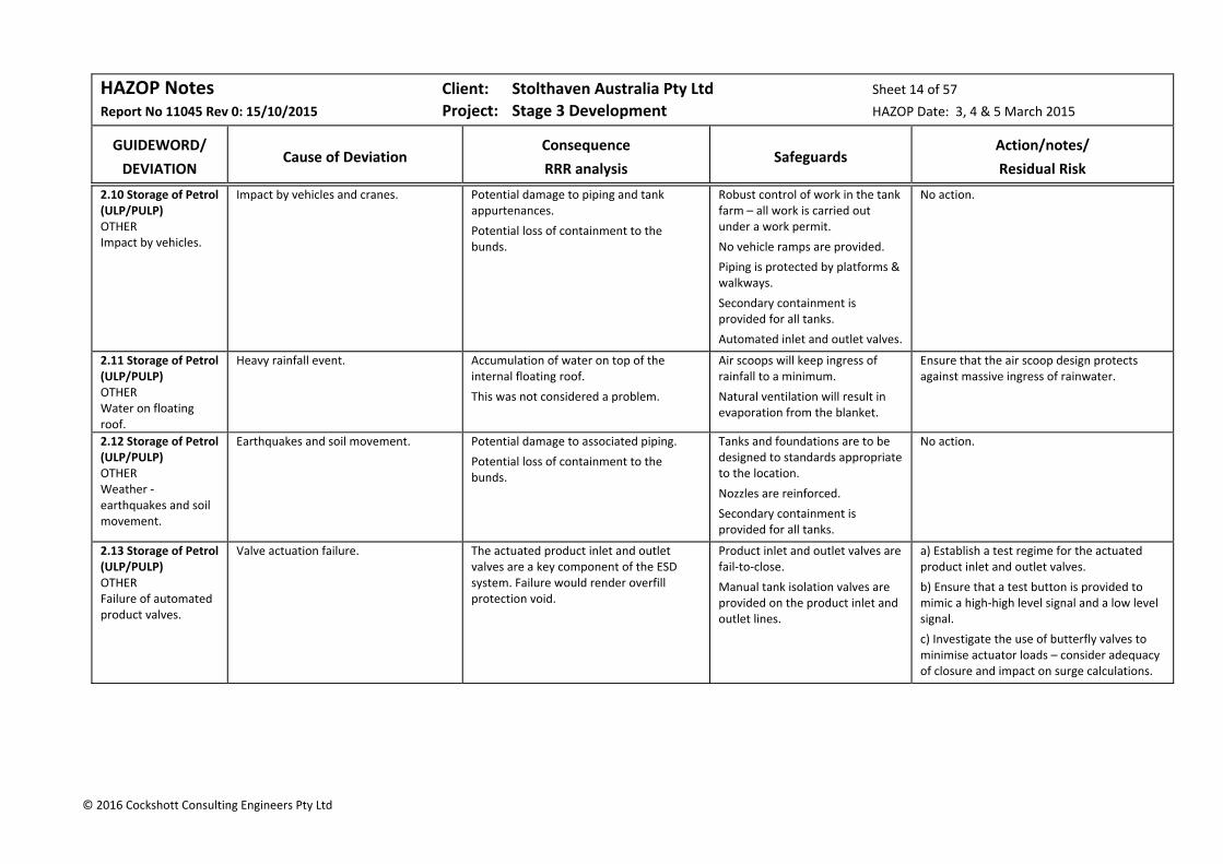
HAZOP Notes Client: Stolthaven Australia Pty Ltd Sheet 14 of 57
Report No 11045 Rev 0: 15/10/2015 Project: Stage 3 Development HAZOP Date: 3, 4 & 5 March 2015
GUIDEWORD/
DEVIATION
Cause of Deviation
Consequence
RRR analysis
Safeguards
Action/notes/
Residual Risk
© 2016 Cockshott Consulting Engineers Pty Ltd
2.10 Storage of Petrol (ULP/PULP) OTHER Impact by vehicles.
Impact by vehicles and cranes. Potential damage to piping and tank appurtenances.
Potential loss of containment to the bunds.
Robust control of work in the tank farm – all work is carried out under a work permit.
No vehicle ramps are provided.
Piping is protected by platforms & walkways.
Secondary containment is provided for all tanks.
Automated inlet and outlet valves.
No action.
2.11 Storage of Petrol (ULP/PULP) OTHER Water on floating roof.
Heavy rainfall event. Accumulation of water on top of the internal floating roof.
This was not considered a problem.
Air scoops will keep ingress of rainfall to a minimum.
Natural ventilation will result in evaporation from the blanket.
Ensure that the air scoop design protects against massive ingress of rainwater.
2.12 Storage of Petrol (ULP/PULP) OTHER Weather ‐ earthquakes and soil movement.
Earthquakes and soil movement. Potential damage to associated piping.
Potential loss of containment to the bunds.
Tanks and foundations are to be designed to standards appropriate to the location.
Nozzles are reinforced.
Secondary containment is provided for all tanks.
No action.
2.13 Storage of Petrol (ULP/PULP) OTHER Failure of automated product valves.
Valve actuation failure. The actuated product inlet and outlet valves are a key component of the ESD system. Failure would render overfill protection void.
Product inlet and outlet valves are fail‐to‐close.
Manual tank isolation valves are provided on the product inlet and outlet lines.
a) Establish a test regime for the actuated product inlet and outlet valves.
b) Ensure that a test button is provided to mimic a high‐high level signal and a low level signal.
c) Investigate the use of butterfly valves to minimise actuator loads – consider adequacy of closure and impact on surge calculations.

HAZOP Notes Client: Stolthaven Australia Pty Ltd Sheet 15 of 57
Report No 11045 Rev 0: 15/10/2015 Project: Stage 3 Development HAZOP Date: 3, 4 & 5 March 2015
GUIDEWORD/
DEVIATION
Cause of Deviation
Consequence
RRR analysis
Safeguards
Action/notes/
Residual Risk
© 2016 Cockshott Consulting Engineers Pty Ltd
Node 3: Petrol Loadout (ULP & PULP) (P&IDs: 236974‐0000‐DRG‐PFD‐011‐B, ‐201‐B, ‐202‐B/302‐B & 401‐B)
Tank ND‐10 is taken as the exemplar for this node.
All ULP/PULP will be loaded to the southern 6‐bay gantry(Bays 1 & 2 dedicated for one client; bays 3 & 4 to a second; bays 5 & 6 to be allocated).
Petrol tanks have a low level drawoff and a stripping drawoff from the central sump.
Each tank is provided with a take‐off manifold which will be configured to use a dedicated pump with access to a spare/recirculation pump. The manifolds are designed to accommodate future change of tank allocation, with simple pipe spool changes. The pump bays are roofed.
Thus, for Tank T10 (PUMA), the outlet manifold is connected to the PUMP PULP Pump and the Spare/Recirculation Pump; similarly, Tank T11 & T12 (VIVA) manifolds are connected to the three VIVA pumps and the Spare/Recirculation Pump.
The Tank T10 (PUMA PULP) pump discharge has a dropper in both Bays 1 &2, each connected to a single loading arm in that bay.
One pump is capable of serving three arms (7,500 LPM). Tanker vapours are extracted from the gantry to the Vapour Recovery Unit (VRU). Whereas T10 is connected to only two arms, other tanks can be connected to three or four arms.
The gantry, which will operate 24/7, is roofed, has protective bollards, IR fire detection, UV smoke detection and foam deluge.
3.1 Petrol Loadout NONE No flow to loadout pump.
Construction swarf in commissioning strainer.
Pump could run dry and overheat leading to a seal failure and loss of containment.
Pressure indicator on pump suction (during commissioning, when the strainer is in place).
FLS on pump discharge which will shut down the pump (with timer delay).
No action.
3.2 Petrol Loadout NONE No flow to loadout pump.
Incorrect line‐up (to standby pump or other client loadout pump).
Incorrect line‐up to wrong header.
Loading will not proceed until the correct line‐up is made.
Safeguards considered adequate.
The Loading Control System ensures that the tank/pump/arm combination is appropriate for the requested operation.
FLS on pump discharge which will shut down the pump (with timer delay).
No action.
3.3 Petrol Loadout NONE Loss of power.
Power loss is infrequent at the site. The Loading Control System remembers the last load and after resets are made and permissives are reloaded, will recommence with a low flow ramp up.
Safeguards considered adequate.
Independent Substation and MCCs.
A level of redundancy is being added to the servers.
No action.
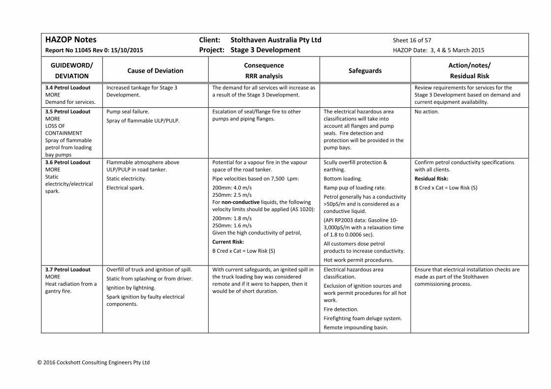
HAZOP Notes Client: Stolthaven Australia Pty Ltd Sheet 16 of 57
Report No 11045 Rev 0: 15/10/2015 Project: Stage 3 Development HAZOP Date: 3, 4 & 5 March 2015
GUIDEWORD/
DEVIATION
Cause of Deviation
Consequence
RRR analysis
Safeguards
Action/notes/
Residual Risk
© 2016 Cockshott Consulting Engineers Pty Ltd
3.4 Petrol Loadout MORE Demand for services.
Increased tankage for Stage 3 Development.
The demand for all services will increase as a result of the Stage 3 Development.
Review requirements for services for the Stage 3 Development based on demand and current equipment availability.
3.5 Petrol Loadout MORE LOSS OF CONTAINMENT Spray of flammable petrol from loading bay pumps
Pump seal failure.
Spray of flammable ULP/PULP.
Escalation of seal/flange fire to other pumps and piping flanges.
The electrical hazardous area classifications will take into account all flanges and pump seals. Fire detection and protection will be provided in the pump bays.
No action.
3.6 Petrol Loadout MORE Static electricity/electrical spark.
Flammable atmosphere above ULP/PULP in road tanker.
Static electricity.
Electrical spark.
Potential for a vapour fire in the vapour space of the road tanker.
Pipe velocities based on 7,500 Lpm:
200mm: 4.0 m/s 250mm: 2.5 m/s For non‐conductive liquids, the following velocity limits should be applied (AS 1020):
200mm: 1.8 m/s 250mm: 1.6 m/s Given the high conductivity of petrol,
Current Risk:
B Cred x Cat = Low Risk (S)
Scully overfill protection & earthing.
Bottom loading.
Ramp pup of loading rate.
Petrol generally has a conductivity >50pS/m and is considered as a conductive liquid.
(API RP2003 data: Gasoline 10‐3,000pS/m with a relaxation time of 1.8 to 0.0006 sec).
All customers dose petrol products to increase conductivity.
Hot work permit procedures.
Confirm petrol conductivity specifications with all clients.
Residual Risk:
B Cred x Cat = Low Risk (S)
3.7 Petrol Loadout MORE Heat radiation from a gantry fire.
Overfill of truck and ignition of spill.
Static from splashing or from driver.
Ignition by lightning.
Spark ignition by faulty electrical components.
With current safeguards, an ignited spill in the truck loading bay was considered remote and if it were to happen, then it would be of short duration.
Electrical hazardous area classification.
Exclusion of ignition sources and work permit procedures for all hot work.
Fire detection.
Firefighting foam deluge system.
Remote impounding basin.
Ensure that electrical installation checks are made as part of the Stolthaven commissioning process.
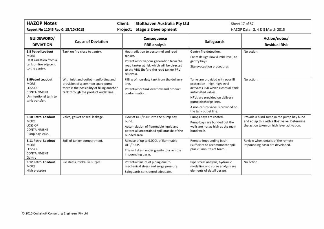
HAZOP Notes Client: Stolthaven Australia Pty Ltd Sheet 17 of 57
Report No 11045 Rev 0: 15/10/2015 Project: Stage 3 Development HAZOP Date: 3, 4 & 5 March 2015
GUIDEWORD/
DEVIATION
Cause of Deviation
Consequence
RRR analysis
Safeguards
Action/notes/
Residual Risk
© 2016 Cockshott Consulting Engineers Pty Ltd
3.8 Petrol Loadout MORE Heat radiation from a tank on fire adjacent to the gantry.
Tank on fire close to gantry. Heat radiation to personnel and road tanker.
Potential for vapour generation from the road tanker at risk which will be directed to the VRU (before the road tanker PRV relieves).
Gantry fire detection.
Foam deluge (low & mid‐level) to gantry bays.
Site evacuation procedures.
No action.
3.9Petrol Loadout MORE LOSS OF CONTAINMENT Unintentional tank to tank transfer.
With inlet and outlet manifolding and provision of a common spare pump, there is the possibility of filling another tank through the product outlet line.
Filling of non‐duty tank from the delivery line.
Potential for tank overflow and product contamination.
Tanks are provided with overfill protection – high‐high level activates ESD which closes all tank automated valves.
NRVs are provided on delivery pump discharge lines.
A non‐return valve is provided on the tank outlet line.
No action.
3.10 Petrol Loadout MORE LOSS OF CONTAINMENT Pump bay leaks.
Valve, gasket or seal leakage. Flow of ULP/PULP into the pump bay bund.
Accumulation of flammable liquid and potential uncontained spill outside of the bunded area.
Pumps bays are roofed.
Pump bays are bunded but the walls are not as high as the main bund walls.
Provide a blind sump in the pump bay bund and equip this with a float valve. Determine the action taken on high level activation.
3.11 Petrol Loadout MORE LOSS OF CONTAINMENT Gantry
Spill of tanker compartment. Release of up to 9,000L of flammable ULP/PULP.
This will drain under gravity to a remote impounding basin.
Remote impounding basin (sufficient to accommodate spill plus 20 minutes of foam).
Review when details of the remote impounding basin are developed.
3.12 Petrol Loadout MORE High pressure
Pie stress, hydraulic surges. Potential failure of piping due to mechanical stress and surge pressure.
Safeguards considered adequate.
Pipe stress analysis, hydraulic modelling and surge analysis are elements of detail design.
No action.

HAZOP Notes Client: Stolthaven Australia Pty Ltd Sheet 18 of 57
Report No 11045 Rev 0: 15/10/2015 Project: Stage 3 Development HAZOP Date: 3, 4 & 5 March 2015
GUIDEWORD/
DEVIATION
Cause of Deviation
Consequence
RRR analysis
Safeguards
Action/notes/
Residual Risk
© 2016 Cockshott Consulting Engineers Pty Ltd
3.13 Petrol Loadout LESS Low level in the storage tank.
Pumping out to gantry beyond safe low level (roof landed).
Floating roof will land, a vacuum will be pulled and air will be introduced through the PVV into the space below the roof.
Ingress of air to the space below the floating roof tank, which will be exhausted to atmosphere when the tank is reprimed.
Fuels manager system (this will change selected tank when the level is at the low set point when manual valves on the switch tank are set).
The system is understood to stop loading, stop the pump and close the tank outlet actuated valve on tank low level.
LAL is interlocked to shut the outlet actuated valve.
a) Contractual arrangements need to reflect that there is a safe low level (before the internal roof is grounded) and product cannot be loaded when the tank is at this level.
b) Concern was expressed about Functional Specification documentation and understanding of what the control system should do and what the system actually does. A review is required to ensure that functional requirements are clearly documented and that the control system meets these requirements.
c) Review the use of low pump motor current as a means of initiating a “stop loading, stop pump and close inlet valve” sequence.
d) Ensure that the tank low level set point is selected so that the floating roof does not ground.
3.14 Petrol Loadout DIFFERENT Dead legs in piping.
Because of the provision of manifolds for future flexibility, there are dead legs:
In the pump suction manifolds;
In the gantry manifolds (pots);
In the gantry headers.
No issues were identified for the pump suction manifolds or gantry manifolds – all are dedicated client/product.
For gantry headers in low numbered bays, there will be a long dead leg from the dropper to the header end.
Provide a spade at the last dropper in the gantry header (number and position to be confirmed).
3.15 Petrol Loadout OTHER Truck impact.
Truck leaving the roadway between the islands.
Potential damage to truck loading bay components. Unlikely to lead to a hazardous event as the truck is not being filled, but would have commercial implications during repair works.
Low speed entry and exit to loading bay.
Kerb protection.
Good lighting and well defined entry.
Trained DG drivers.
Review the width of the islands in the truck loading bay and determine if the road can be widened between bays.
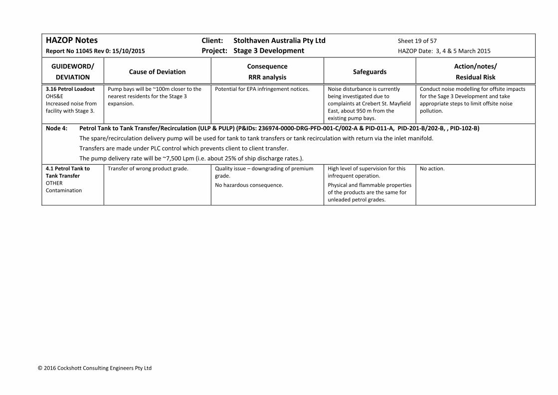
HAZOP Notes Client: Stolthaven Australia Pty Ltd Sheet 19 of 57
Report No 11045 Rev 0: 15/10/2015 Project: Stage 3 Development HAZOP Date: 3, 4 & 5 March 2015
GUIDEWORD/
DEVIATION
Cause of Deviation
Consequence
RRR analysis
Safeguards
Action/notes/
Residual Risk
© 2016 Cockshott Consulting Engineers Pty Ltd
3.16 Petrol Loadout OHS&E Increased noise from facility with Stage 3.
Pump bays will be ~100m closer to the nearest residents for the Stage 3 expansion.
Potential for EPA infringement notices. Noise disturbance is currently being investigated due to complaints at Crebert St. Mayfield East, about 950 m from the existing pump bays.
Conduct noise modelling for offsite impacts for the Sage 3 Development and take appropriate steps to limit offsite noise pollution.
Node 4: Petrol Tank to Tank Transfer/Recirculation (ULP & PULP) (P&IDs: 236974‐0000‐DRG‐PFD‐001‐C/002‐A & PID‐011‐A, PID‐201‐B/202‐B, , PID‐102‐B)
The spare/recirculation delivery pump will be used for tank to tank transfers or tank recirculation with return via the inlet manifold.
Transfers are made under PLC control which prevents client to client transfer.
The pump delivery rate will be ~7,500 Lpm (i.e. about 25% of ship discharge rates.).
4.1 Petrol Tank to Tank Transfer OTHER Contamination
Transfer of wrong product grade. Quality issue – downgrading of premium grade.
No hazardous consequence.
High level of supervision for this infrequent operation.
Physical and flammable properties of the products are the same for unleaded petrol grades.
No action.
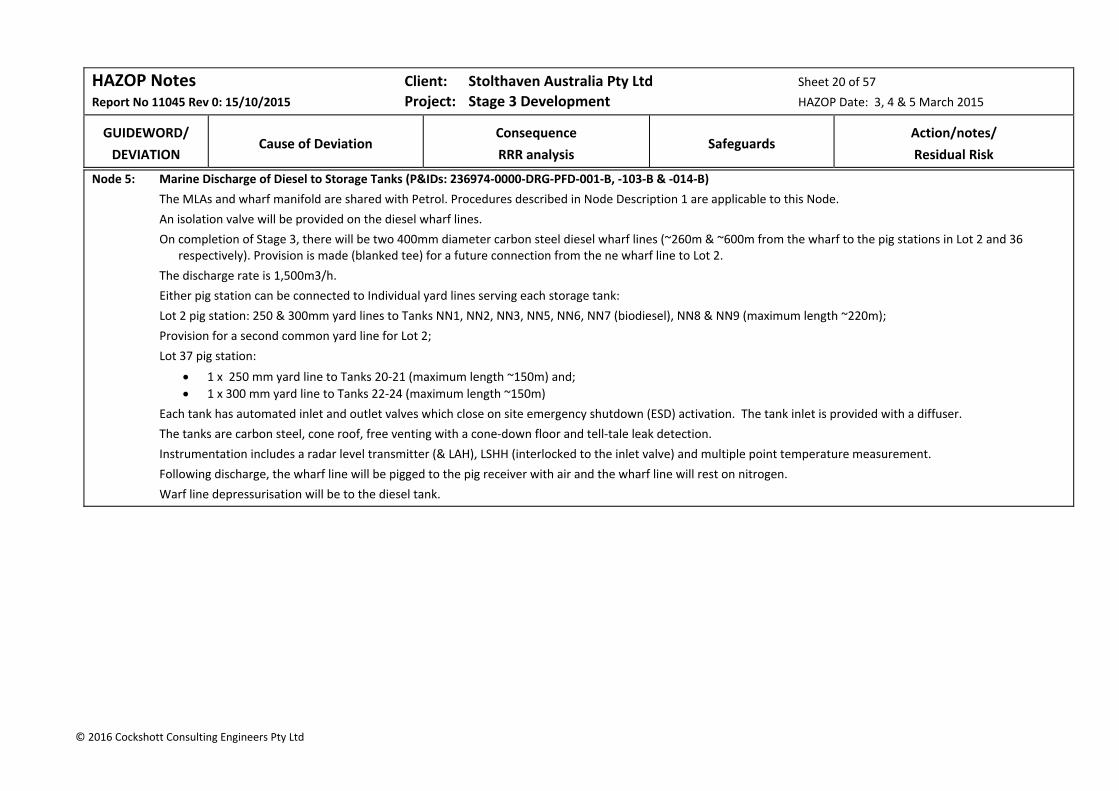
HAZOP Notes Client: Stolthaven Australia Pty Ltd Sheet 20 of 57
Report No 11045 Rev 0: 15/10/2015 Project: Stage 3 Development HAZOP Date: 3, 4 & 5 March 2015
GUIDEWORD/
DEVIATION
Cause of Deviation
Consequence
RRR analysis
Safeguards
Action/notes/
Residual Risk
© 2016 Cockshott Consulting Engineers Pty Ltd
Node 5: Marine Discharge of Diesel to Storage Tanks (P&IDs: 236974‐0000‐DRG‐PFD‐001‐B, ‐103‐B & ‐014‐B)
The MLAs and wharf manifold are shared with Petrol. Procedures described in Node Description 1 are applicable to this Node.
An isolation valve will be provided on the diesel wharf lines.
On completion of Stage 3, there will be two 400mm diameter carbon steel diesel wharf lines (~260m & ~600m from the wharf to the pig stations in Lot 2 and 36 respectively). Provision is made (blanked tee) for a future connection from the ne wharf line to Lot 2.
The discharge rate is 1,500m3/h.
Either pig station can be connected to Individual yard lines serving each storage tank:
Lot 2 pig station: 250 & 300mm yard lines to Tanks NN1, NN2, NN3, NN5, NN6, NN7 (biodiesel), NN8 & NN9 (maximum length ~220m);
Provision for a second common yard line for Lot 2;
Lot 37 pig station:
1 x 250 mm yard line to Tanks 20‐21 (maximum length ~150m) and;
1 x 300 mm yard line to Tanks 22‐24 (maximum length ~150m)
Each tank has automated inlet and outlet valves which close on site emergency shutdown (ESD) activation. The tank inlet is provided with a diffuser.
The tanks are carbon steel, cone roof, free venting with a cone‐down floor and tell‐tale leak detection.
Instrumentation includes a radar level transmitter (& LAH), LSHH (interlocked to the inlet valve) and multiple point temperature measurement.
Following discharge, the wharf line will be pigged to the pig receiver with air and the wharf line will rest on nitrogen.
Warf line depressurisation will be to the diesel tank.
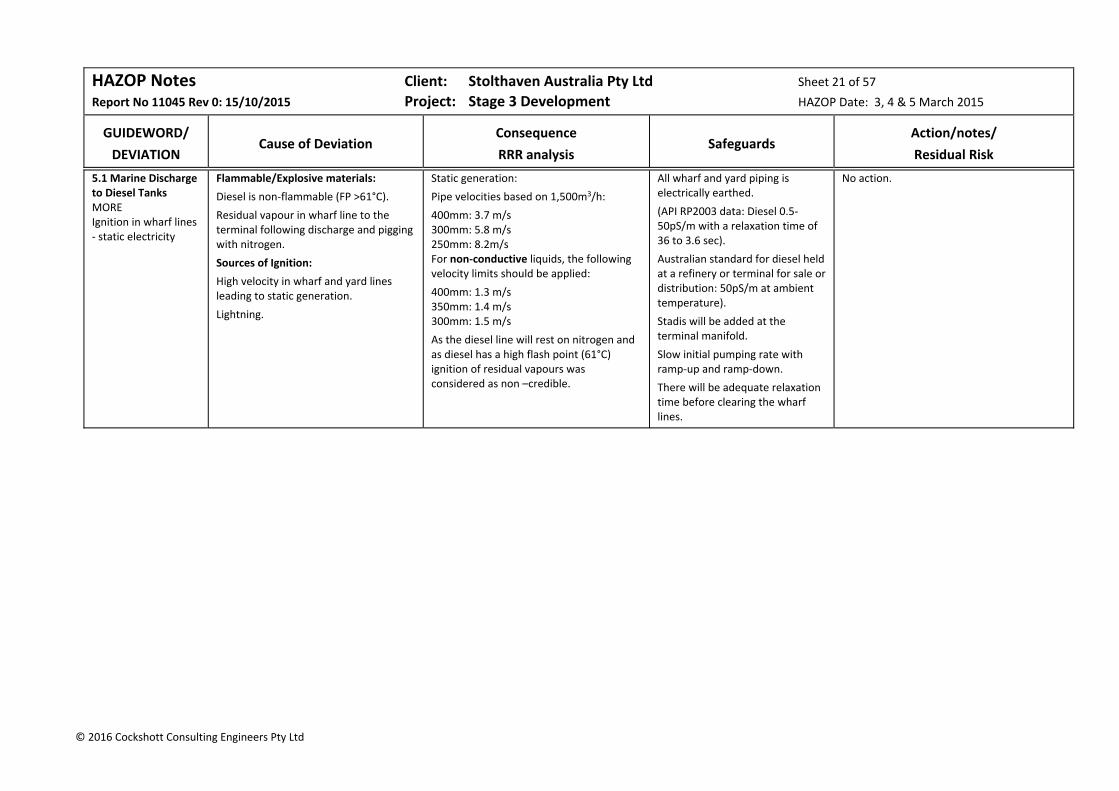
HAZOP Notes Client: Stolthaven Australia Pty Ltd Sheet 21 of 57
Report No 11045 Rev 0: 15/10/2015 Project: Stage 3 Development HAZOP Date: 3, 4 & 5 March 2015
GUIDEWORD/
DEVIATION
Cause of Deviation
Consequence
RRR analysis
Safeguards
Action/notes/
Residual Risk
© 2016 Cockshott Consulting Engineers Pty Ltd
5.1 Marine Discharge to Diesel Tanks MORE Ignition in wharf lines ‐ static electricity
Flammable/Explosive materials:
Diesel is non‐flammable (FP >61°C).
Residual vapour in wharf line to the terminal following discharge and pigging with nitrogen.
Sources of Ignition:
High velocity in wharf and yard lines leading to static generation.
Lightning.
Static generation:
Pipe velocities based on 1,500m3/h:
400mm: 3.7 m/s 300mm: 5.8 m/s 250mm: 8.2m/s For non‐conductive liquids, the following velocity limits should be applied:
400mm: 1.3 m/s 350mm: 1.4 m/s 300mm: 1.5 m/s
As the diesel line will rest on nitrogen and as diesel has a high flash point (61°C) ignition of residual vapours was considered as non –credible.
All wharf and yard piping is electrically earthed.
(API RP2003 data: Diesel 0.5‐50pS/m with a relaxation time of 36 to 3.6 sec).
Australian standard for diesel held at a refinery or terminal for sale or distribution: 50pS/m at ambient temperature).
Stadis will be added at the terminal manifold.
Slow initial pumping rate with ramp‐up and ramp‐down.
There will be adequate relaxation time before clearing the wharf lines.
No action.
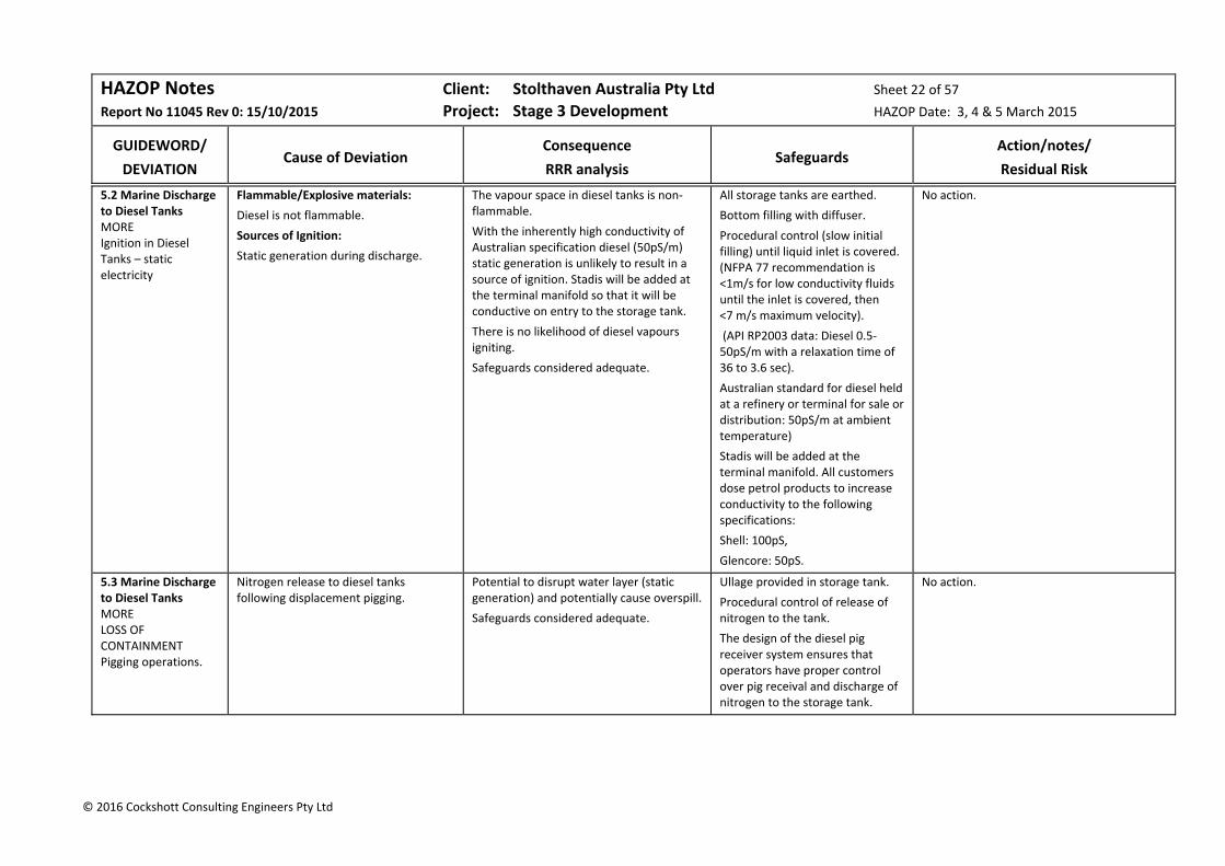
HAZOP Notes Client: Stolthaven Australia Pty Ltd Sheet 22 of 57
Report No 11045 Rev 0: 15/10/2015 Project: Stage 3 Development HAZOP Date: 3, 4 & 5 March 2015
GUIDEWORD/
DEVIATION
Cause of Deviation
Consequence
RRR analysis
Safeguards
Action/notes/
Residual Risk
© 2016 Cockshott Consulting Engineers Pty Ltd
5.2 Marine Discharge to Diesel Tanks MORE Ignition in Diesel Tanks – static electricity
Flammable/Explosive materials:
Diesel is not flammable.
Sources of Ignition:
Static generation during discharge.
The vapour space in diesel tanks is non‐flammable.
With the inherently high conductivity of Australian specification diesel (50pS/m) static generation is unlikely to result in a source of ignition. Stadis will be added at the terminal manifold so that it will be conductive on entry to the storage tank.
There is no likelihood of diesel vapours igniting.
Safeguards considered adequate.
All storage tanks are earthed.
Bottom filling with diffuser.
Procedural control (slow initial filling) until liquid inlet is covered. (NFPA 77 recommendation is <1m/s for low conductivity fluids until the inlet is covered, then <7 m/s maximum velocity).
(API RP2003 data: Diesel 0.5‐50pS/m with a relaxation time of 36 to 3.6 sec).
Australian standard for diesel held at a refinery or terminal for sale or distribution: 50pS/m at ambient temperature)
Stadis will be added at the terminal manifold. All customers dose petrol products to increase conductivity to the following specifications:
Shell: 100pS,
Glencore: 50pS.
No action.
5.3 Marine Discharge to Diesel Tanks MORE LOSS OF CONTAINMENT Pigging operations.
Nitrogen release to diesel tanks following displacement pigging.
Potential to disrupt water layer (static generation) and potentially cause overspill.
Safeguards considered adequate.
Ullage provided in storage tank.
Procedural control of release of nitrogen to the tank.
The design of the diesel pig receiver system ensures that operators have proper control over pig receival and discharge of nitrogen to the storage tank.
No action.
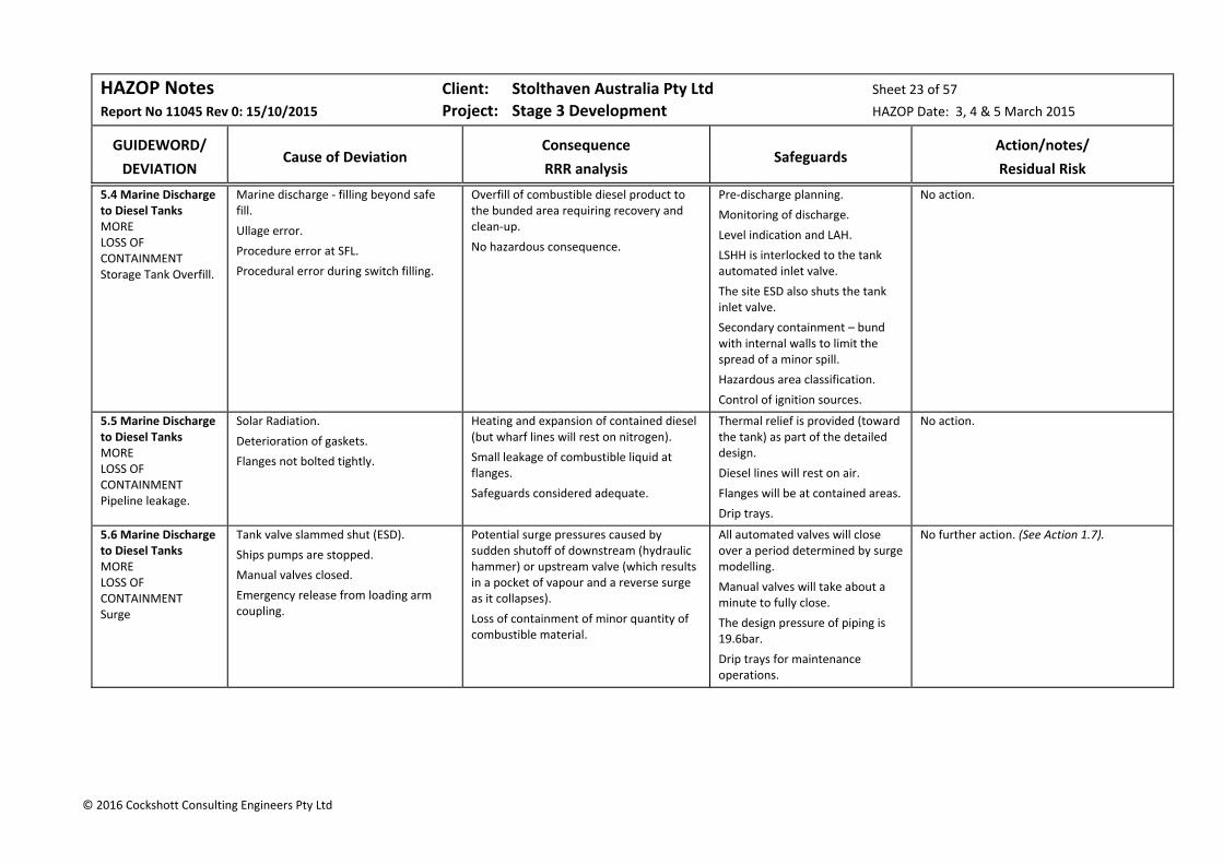
HAZOP Notes Client: Stolthaven Australia Pty Ltd Sheet 23 of 57
Report No 11045 Rev 0: 15/10/2015 Project: Stage 3 Development HAZOP Date: 3, 4 & 5 March 2015
GUIDEWORD/
DEVIATION
Cause of Deviation
Consequence
RRR analysis
Safeguards
Action/notes/
Residual Risk
© 2016 Cockshott Consulting Engineers Pty Ltd
5.4 Marine Discharge to Diesel Tanks MORE LOSS OF CONTAINMENT Storage Tank Overfill.
Marine discharge ‐ filling beyond safe fill.
Ullage error.
Procedure error at SFL.
Procedural error during switch filling.
Overfill of combustible diesel product to the bunded area requiring recovery and clean‐up.
No hazardous consequence.
Pre‐discharge planning.
Monitoring of discharge.
Level indication and LAH.
LSHH is interlocked to the tank automated inlet valve.
The site ESD also shuts the tank inlet valve.
Secondary containment – bund with internal walls to limit the spread of a minor spill.
Hazardous area classification.
Control of ignition sources.
No action.
5.5 Marine Discharge to Diesel Tanks MORE LOSS OF CONTAINMENT Pipeline leakage.
Solar Radiation.
Deterioration of gaskets.
Flanges not bolted tightly.
Heating and expansion of contained diesel (but wharf lines will rest on nitrogen).
Small leakage of combustible liquid at flanges.
Safeguards considered adequate.
Thermal relief is provided (toward the tank) as part of the detailed design.
Diesel lines will rest on air.
Flanges will be at contained areas.
Drip trays.
No action.
5.6 Marine Discharge to Diesel Tanks MORE LOSS OF CONTAINMENT Surge
Tank valve slammed shut (ESD).
Ships pumps are stopped.
Manual valves closed.
Emergency release from loading arm coupling.
Potential surge pressures caused by sudden shutoff of downstream (hydraulic hammer) or upstream valve (which results in a pocket of vapour and a reverse surge as it collapses).
Loss of containment of minor quantity of combustible material.
All automated valves will close over a period determined by surge modelling.
Manual valves will take about a minute to fully close.
The design pressure of piping is 19.6bar.
Drip trays for maintenance operations.
No further action. (See Action 1.7).

HAZOP Notes Client: Stolthaven Australia Pty Ltd Sheet 24 of 57
Report No 11045 Rev 0: 15/10/2015 Project: Stage 3 Development HAZOP Date: 3, 4 & 5 March 2015
GUIDEWORD/
DEVIATION
Cause of Deviation
Consequence
RRR analysis
Safeguards
Action/notes/
Residual Risk
© 2016 Cockshott Consulting Engineers Pty Ltd
5.7 Marine Discharge to Diesel Tanks MORE Overpressure from ammonium nitrate explosion in port or heat radiation from coal carrier at berth in the channel.
Combustible/Explosive materials:
K2 Berth: bulk ammonium nitrate (2 km).
M4 Berth: packaged ammonium nitrate (1 km).
Coal Bulk Carriers (200m from M7).
Sources of Ignition:
On‐board fire on ammonium nitrate ship at K2;
Contamination of ammonium nitrate with organic materials;
Coal fire in Coal bulk carrier hold.
Blast impact from bulk or packaged ammonium nitrate explosion.
Based on the results of consequence analysis, the impact of an ammonium nitrate explosion at K2 to personnel and assets at M7 was considered to be minor.
Based on the results of consequence analysis, the impact of a bulk carrier coal fire across the channel to personnel and assets at M7 was considered to be insignificant.
A knock‐on scenario involving release of diesel was considered non‐credible.
Current Risk:
E Rare x Min = Neg Risk (S)
External event which is not controlled by Stolthaven.
Diesel is not flammable.
No further action (See Action 1.8)
Residual Risk:
E Rare x Min = Neg Risk (S)
5.8 Marine Discharge to Diesel Tanks MORE Heat radiation at the wharf from a tank fire at the Terminal.
Fire at the Newcastle Bulk Liquids Terminal.
No development of Lot 1 is included in the Stage 3 Development.
Tank top fire with heat radiation effects at the wharf.
Based on the results of consequence analysis, a tank‐top fire in Lot 37 has no impact to personnel or wharf assets (see main report).
Safeguards considered adequate.
Terminal fire detection and protection in accordance with AS1940 and Fire Safety Study.
Terminal Hot Work Permit procedures, exclusion of ignition sources and compliance with Hazardous Area Classification.
Emergency release couplings (ERC) incorporated in the MLA.
No action.
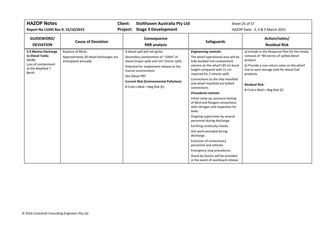
HAZOP Notes Client: Stolthaven Australia Pty Ltd Sheet 25 of 57
Report No 11045 Rev 0: 15/10/2015 Project: Stage 3 Development HAZOP Date: 3, 4 & 5 March 2015
GUIDEWORD/
DEVIATION
Cause of Deviation
Consequence
RRR analysis
Safeguards
Action/notes/
Residual Risk
© 2016 Cockshott Consulting Engineers Pty Ltd
5.9 Marine Discharge to Diesel Tanks MORE Loss of containment at the Mayfield 7 Berth
Rupture of MLAs.
Approximately 30 diesel discharges are anticipated annually.
A diesel spill will not ignite.
Secondary containment of ~100m3 of diesel (major spill) and 1m3 (minor spill).
Potential for inadvertent release to the marine environment.
See Diesel PBT
Current Risk (Environmental Pollution):
B Cred x Mod = Neg Risk (E)
Engineering controls:
The wharf operational area will be fully bunded Full containment volume on the wharf (30 cm bund height compared with 11 cm required for 2 minute spill).
Connections to the ship manifold and wharf manifold are bolted connections.
Procedural controls:
Initial ramp‐up, pressure testing of MLA and flanged connections with nitrogen and inspection for leaks.
Ongoing supervision by several personnel during discharge.
Earthing continuity checks.
Hot work excluded during discharge.
Exclusion of unnecessary personnel and vehicles
Emergency stop procedures.
Stand‐by booms will be provided in the event of overboard release.
a) Include in the Response Plan for the timely removal of ~84 tonnes of spilled diesel product.
b) Provide a non‐return valve on the wharf line to each storage tank for diesel fuel products.
Residual Risk:
B Cred x Mod = Neg Risk (E)

HAZOP Notes Client: Stolthaven Australia Pty Ltd Sheet 26 of 57
Report No 11045 Rev 0: 15/10/2015 Project: Stage 3 Development HAZOP Date: 3, 4 & 5 March 2015
GUIDEWORD/
DEVIATION
Cause of Deviation
Consequence
RRR analysis
Safeguards
Action/notes/
Residual Risk
© 2016 Cockshott Consulting Engineers Pty Ltd
5.10 Marine Discharge to Diesel Tanks MORE High Kinetic Energy
High winds.
Passing ships.
Potential for MLA disconnection.
Risks are covered in Notes 3.3 and 3.4 (incorporated in loading arm failure rates).
The bulk liquid carrier is loaded in accordance with the IMDG Code, providing separation of non‐compatible cargoes.
Vessels are double‐hulled in accordance with Marpol 1 & 2, preventing external damage (e.g. on berthing) from release of fuels or chemicals.
Port of Newcastle Ship Handling Safety Guidelines.
A mooring Study and a Ship Interaction Study will be performed to determine final mooring requirements and impacts.
No action.
5.11 Marine Discharge to Diesel Tanks OTHER Vehicle impact.
Impact of vehicles with pipeline structural supports.
Pipeline rupture.
Loss of containment to the marine or soil environment.
Safeguards considered adequate.
Site security (gatehouse). The gatehouse will be manned during discharge.
Protection of structural supports.
The pipebridge towers will be placed to avoid proximity to traffic.
The pipelines over the pipebridge will not rest on product.
No action.
5.12 Marine Discharge to Diesel Tanks OTHER Vehicle impact during Koppers discharge operations.
Koppers will require access for line walks during discharge of their products.
Potential vehicle impacts with terminal infrastructure if access is provided for vehicles along the pipeline.
Fire access will be maintained.
Protection of structural supports.
The pipebridge towers will be placed to avoid proximity to traffic.
The pipelines over the pipebridge will not rest on product.
No further action (See Action 1.14).
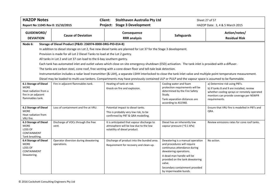
HAZOP Notes Client: Stolthaven Australia Pty Ltd Sheet 27 of 57
Report No 11045 Rev 0: 15/10/2015 Project: Stage 3 Development HAZOP Date: 3, 4 & 5 March 2015
GUIDEWORD/
DEVIATION
Cause of Deviation
Consequence
RRR analysis
Safeguards
Action/notes/
Residual Risk
© 2016 Cockshott Consulting Engineers Pty Ltd
Node 6: Storage of Diesel Product (P&ID: 236974‐0000‐DRG‐PID‐014‐B)
In addition to diesel storage on Lot 2, five new diesel tanks are planned for Lot 37 for the Stage 3 development.
Provision is made for all Lot 2 Diesel Tanks to load at the Lot 2 gantry.
All tanks in Lot 2 and Lot 37 can load to the 6‐bay southern gantry.
Each tank has automated inlet and outlet valves which close on site emergency shutdown (ESD) activation. The tank inlet is provided with a diffuser.
The tanks are carbon steel, cone roof, free venting with a cone‐down floor and tell‐tale leak detection.
Instrumentation includes a radar level transmitter (& LAH), a separate LSHH interlocked to close the tank inlet valve and multiple point temperature measurement.
Diesel may be loaded to multi‐use tankers. Compartments may have previously contained ULP or PULP and the vapour space is assumed to be flammable.
6.1 Storage of Diesel MORE Heat radiation from a fire in an adjacent flammables tank.
Fire in adjacent flammables tank. Heating of tank‐at‐risk.
Knock‐on fire and explosion.
Cooling water and foam protection requirements will be determined by the Fire Safety Study.
Tank separation distances are according to AS1940.
a) Determine risk using PBTs.
b) If tanks 8 and 9 are installed, review whether cooling sprays or remotely operated monitors can provide coverage per NSWFR requirements.
6.2 Storage of Diesel MORE Heat radiation from VRU fire.
Loss of containment and fire at VRU. Potential impact to diesel tanks.
This is probably very low risk, to be confirmed by PBT & QRA modelling.
Ensure that VRU fire is modelled in PBTs and QRA.
6.3 Storage of Diesel MORE LOSS OF CONTAINMENT Tank breathing.
Discharge of VOCs through the free vent.
It is anticipated that vapour discharge to atmosphere will be low due to the low volatility of diesel product.
Diesel has an inherently low vapour pressure (~0.1 kPa)
Review emissions rates for cone roof tanks.
6.4 Storage of Diesel MORE LOSS OF CONTAINMENT Dewatering.
Operator diversion during dewatering operations.
Discharge of product into the bunded area.
Requirement for recovery and clean‐up.
Dewatering is a manual operation and procedures will require continuous attendance during dewatering operations.
A dead‐man handle will be provided on the tank dewatering valve.
Secondary containment provided by impermeable bunds.
No action.
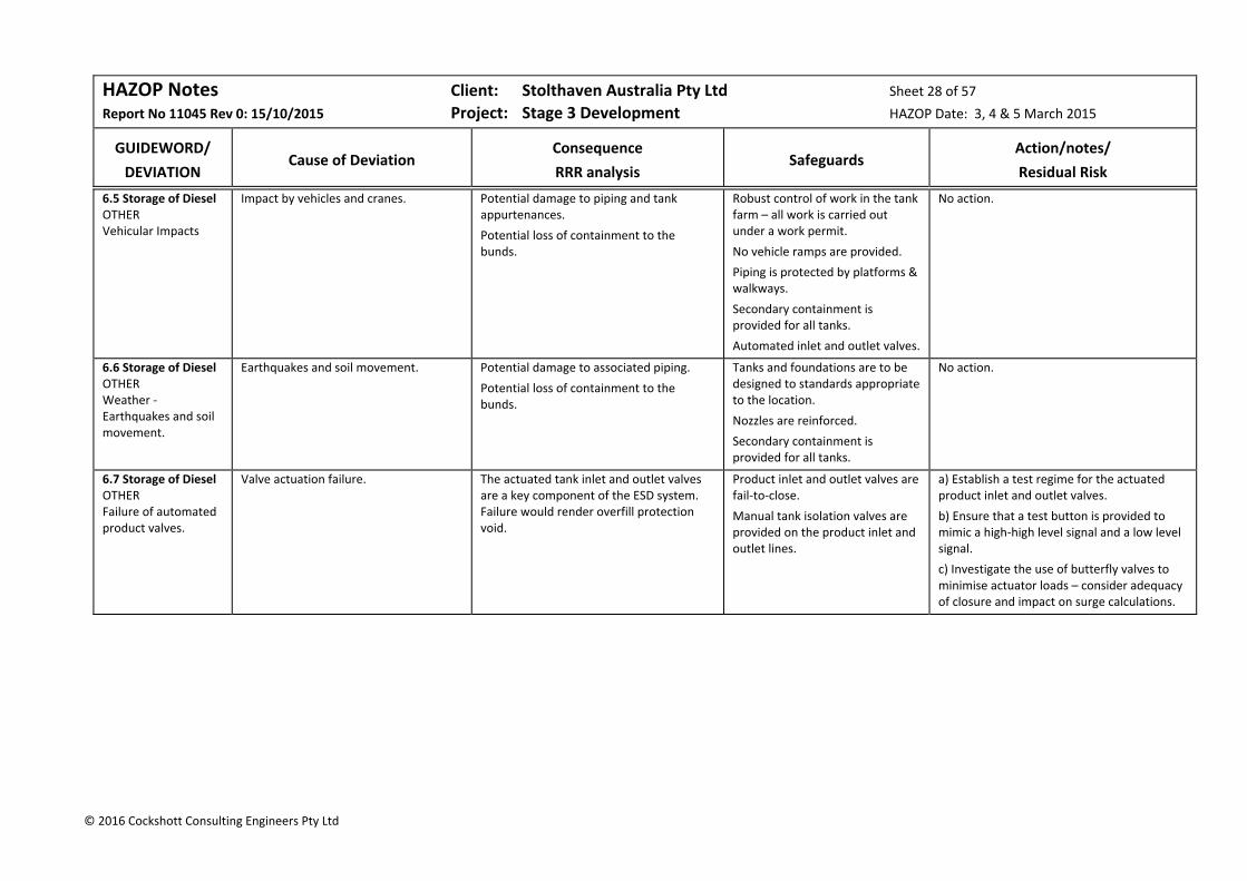
HAZOP Notes Client: Stolthaven Australia Pty Ltd Sheet 28 of 57
Report No 11045 Rev 0: 15/10/2015 Project: Stage 3 Development HAZOP Date: 3, 4 & 5 March 2015
GUIDEWORD/
DEVIATION
Cause of Deviation
Consequence
RRR analysis
Safeguards
Action/notes/
Residual Risk
© 2016 Cockshott Consulting Engineers Pty Ltd
6.5 Storage of Diesel OTHER Vehicular Impacts
Impact by vehicles and cranes. Potential damage to piping and tank appurtenances.
Potential loss of containment to the bunds.
Robust control of work in the tank farm – all work is carried out under a work permit.
No vehicle ramps are provided.
Piping is protected by platforms & walkways.
Secondary containment is provided for all tanks.
Automated inlet and outlet valves.
No action.
6.6 Storage of Diesel OTHER Weather ‐ Earthquakes and soil movement.
Earthquakes and soil movement. Potential damage to associated piping.
Potential loss of containment to the bunds.
Tanks and foundations are to be designed to standards appropriate to the location.
Nozzles are reinforced.
Secondary containment is provided for all tanks.
No action.
6.7 Storage of Diesel OTHER Failure of automated product valves.
Valve actuation failure. The actuated tank inlet and outlet valves are a key component of the ESD system. Failure would render overfill protection void.
Product inlet and outlet valves are fail‐to‐close.
Manual tank isolation valves are provided on the product inlet and outlet lines.
a) Establish a test regime for the actuated product inlet and outlet valves.
b) Ensure that a test button is provided to mimic a high‐high level signal and a low level signal.
c) Investigate the use of butterfly valves to minimise actuator loads – consider adequacy of closure and impact on surge calculations.

HAZOP Notes Client: Stolthaven Australia Pty Ltd Sheet 29 of 57
Report No 11045 Rev 0: 15/10/2015 Project: Stage 3 Development HAZOP Date: 3, 4 & 5 March 2015
GUIDEWORD/
DEVIATION
Cause of Deviation
Consequence
RRR analysis
Safeguards
Action/notes/
Residual Risk
© 2016 Cockshott Consulting Engineers Pty Ltd
Node 7: Diesel Loadout (PIDs: 236974‐0000‐DRG‐PID‐014‐B, ‐205‐B, 301‐B, 402‐B & 404‐B)
The terminal will be configured for two clients.
Provision is made for all Lot 2 Diesel Tanks to load at the Lot 2 gantry.
VIVA tanks in Lot 2 and PUMA tanks in Lot 37 can load to the new 6‐bay southern gantry.
The new Diesel tanks in Lot 37 are provided with take‐offs to four duty pumps and one standby/circulation pump. The pump bays are roofed.
Each tank has a low level drawoff and a stripping drawoff from the central sump.
One pump is capable of serving three arms. Vapours are extracted from the gantry to the Vapour Recovery Unit (VRU)
The gantry, which will operate 24/7, is roofed, have protective bollards, IR fire detection, UV smoke detection and foam deluge.
7.1 Diesel Loadout MORE Leaks and sprays from the loadout pumps.
Pump seal failure.
Spray of combustible diesel (which may be flammable due to mist generation).
Escalation of seal/flange fire to other pumps and piping flanges.
The electrical hazardous area classifications will take account of all flanges and pump seals.
Provide fire detection and protection in the pump bays.
7.2 Diesel Loadout MORE Static electricity generated during loading.
Flammable atmosphere may exist above diesel as road tankers are multi‐use.
Static electricity.
Electrical spark.
Potential for a vapour fire in the vapour space of the road tanker.
Pipe velocities based on 7,500 Lpm:
200mm: 4.0 m/s 250mm: 2.5 m/s For non‐conductive liquids, the following velocity limits should be applied (AS 1020):
200mm: 1.8 m/s 250mm: 1.6 m/s Given the high conductivity of dosed diesel:
Current Risk:
B Cred x Cat = Low Risk (S)
Scully overfill protection & earthing.
Bottom loading.
Ramp pup of loading rate.
(API RP2003 data: Diesel 0.5‐50pS/m with a relaxation time of 36 to 3.6 sec).
Australian standard for diesel held at a refinery or terminal for sale or distribution: 50pS/m at ambient temperature).
All customers dose diesel products to increase conductivity to the following specifications:
Shell: 100pS,
Glencore: 50pS/m
a) Confirm diesel conductivity specifications and quality assurance with PUMA.
b) Confirm diesel delivery manifold sizes and velocities.
Residual Risk:
B Cred x Cat = Low Risk (S)
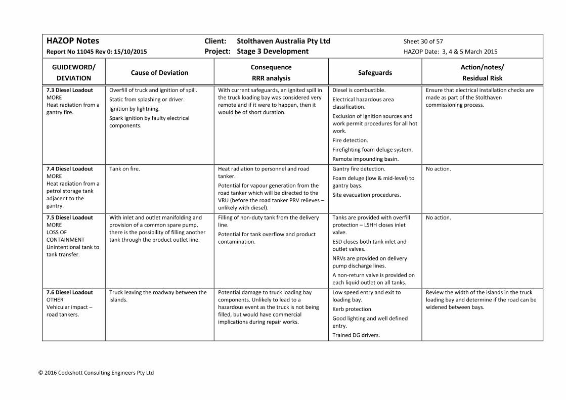
HAZOP Notes Client: Stolthaven Australia Pty Ltd Sheet 30 of 57
Report No 11045 Rev 0: 15/10/2015 Project: Stage 3 Development HAZOP Date: 3, 4 & 5 March 2015
GUIDEWORD/
DEVIATION
Cause of Deviation
Consequence
RRR analysis
Safeguards
Action/notes/
Residual Risk
© 2016 Cockshott Consulting Engineers Pty Ltd
7.3 Diesel Loadout MORE Heat radiation from a gantry fire.
Overfill of truck and ignition of spill.
Static from splashing or driver.
Ignition by lightning.
Spark ignition by faulty electrical components.
With current safeguards, an ignited spill in the truck loading bay was considered very remote and if it were to happen, then it would be of short duration.
Diesel is combustible.
Electrical hazardous area classification.
Exclusion of ignition sources and work permit procedures for all hot work.
Fire detection.
Firefighting foam deluge system.
Remote impounding basin.
Ensure that electrical installation checks are made as part of the Stolthaven commissioning process.
7.4 Diesel Loadout MORE Heat radiation from a petrol storage tank adjacent to the gantry.
Tank on fire. Heat radiation to personnel and road tanker.
Potential for vapour generation from the road tanker which will be directed to the VRU (before the road tanker PRV relieves – unlikely with diesel).
Gantry fire detection.
Foam deluge (low & mid‐level) to gantry bays.
Site evacuation procedures.
No action.
7.5 Diesel Loadout MORE LOSS OF CONTAINMENT Unintentional tank to tank transfer.
With inlet and outlet manifolding and provision of a common spare pump, there is the possibility of filling another tank through the product outlet line.
Filling of non‐duty tank from the delivery line.
Potential for tank overflow and product contamination.
Tanks are provided with overfill protection – LSHH closes inlet valve.
ESD closes both tank inlet and outlet valves.
NRVs are provided on delivery pump discharge lines.
A non‐return valve is provided on each liquid outlet on all tanks.
No action.
7.6 Diesel Loadout OTHER Vehicular impact – road tankers.
Truck leaving the roadway between the islands.
Potential damage to truck loading bay components. Unlikely to lead to a hazardous event as the truck is not being filled, but would have commercial implications during repair works.
Low speed entry and exit to loading bay.
Kerb protection.
Good lighting and well defined entry.
Trained DG drivers.
Review the width of the islands in the truck loading bay and determine if the road can be widened between bays.
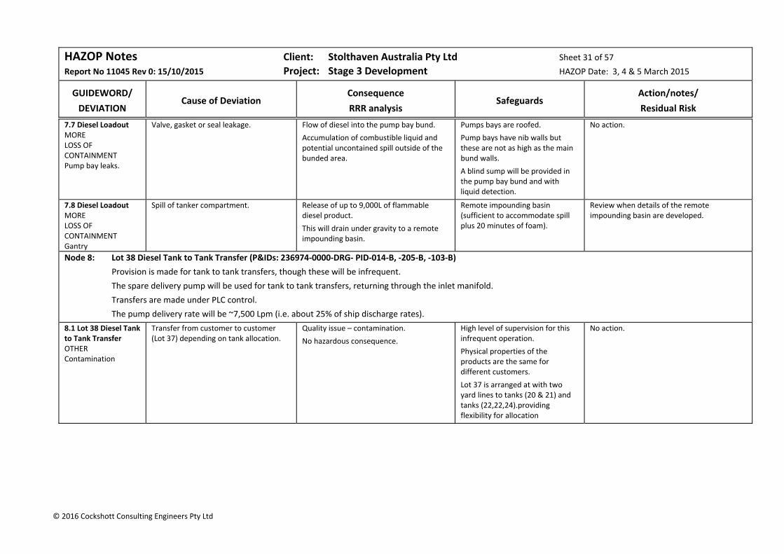
HAZOP Notes Client: Stolthaven Australia Pty Ltd Sheet 31 of 57
Report No 11045 Rev 0: 15/10/2015 Project: Stage 3 Development HAZOP Date: 3, 4 & 5 March 2015
GUIDEWORD/
DEVIATION
Cause of Deviation
Consequence
RRR analysis
Safeguards
Action/notes/
Residual Risk
© 2016 Cockshott Consulting Engineers Pty Ltd
7.7 Diesel Loadout MORE LOSS OF CONTAINMENT Pump bay leaks.
Valve, gasket or seal leakage. Flow of diesel into the pump bay bund.
Accumulation of combustible liquid and potential uncontained spill outside of the bunded area.
Pumps bays are roofed.
Pump bays have nib walls but these are not as high as the main bund walls.
A blind sump will be provided in the pump bay bund and with liquid detection.
No action.
7.8 Diesel Loadout MORE LOSS OF CONTAINMENT Gantry
Spill of tanker compartment. Release of up to 9,000L of flammable diesel product.
This will drain under gravity to a remote impounding basin.
Remote impounding basin (sufficient to accommodate spill plus 20 minutes of foam).
Review when details of the remote impounding basin are developed.
Node 8: Lot 38 Diesel Tank to Tank Transfer (P&IDs: 236974‐0000‐DRG‐ PID‐014‐B, ‐205‐B, ‐103‐B)
Provision is made for tank to tank transfers, though these will be infrequent.
The spare delivery pump will be used for tank to tank transfers, returning through the inlet manifold.
Transfers are made under PLC control.
The pump delivery rate will be ~7,500 Lpm (i.e. about 25% of ship discharge rates).
8.1 Lot 38 Diesel Tank to Tank Transfer OTHER Contamination
Transfer from customer to customer (Lot 37) depending on tank allocation.
Quality issue – contamination.
No hazardous consequence.
High level of supervision for this infrequent operation.
Physical properties of the products are the same for different customers.
Lot 37 is arranged at with two yard lines to tanks (20 & 21) and tanks (22,22,24).providing flexibility for allocation
No action.

HAZOP Notes Client: Stolthaven Australia Pty Ltd Sheet 32 of 57
Report No 11045 Rev 0: 15/10/2015 Project: Stage 3 Development HAZOP Date: 3, 4 & 5 March 2015
GUIDEWORD/
DEVIATION
Cause of Deviation
Consequence
RRR analysis
Safeguards
Action/notes/
Residual Risk
© 2016 Cockshott Consulting Engineers Pty Ltd
Node 9: Marine Discharge of Jet Fuel to Storage Tank (Piping routing drawings 030 series Rev B, 236974‐0000‐DRG‐PFD‐001‐A & P&IDs 236974‐0000‐DRG‐P&ID‐013/104‐A)
A single 200mm SCH 10S stainless steel jet fuel wharf line (~440m length) is provided from the wharf to the pig stations in Lot 36.
Jet fuel has a lower vapour pressure than gasoline < 0.1 kPa) and has a flash point >38°C.
A single 200mm SCH 10S stainless steel yard line is connected to T26, which is a lined tank with stainless steel internals. T26 is located in a bund containing other flammable products (petrol and ethanol)
With a discharge rate through the wharf line of 350m3/h, the fluid velocity is 3.0 m/s.
The jet fuel tank has automated inlet and outlet valves which close on site emergency shutdown (ESD) activation. . The tank inlet is provided with a diffuser.
The tank is a free‐venting cone roof tank which has a floating suction. Sample points are provided at various levels (attached to the floating suction).
The tank has a cone‐down floor and is provided with tell‐tale leak detection. Instrumentation includes a radar level transmitter (LAH), separate LSHH interlocked to the automated tank inlet valve and multiple point temperature measurement.
Following discharge, the wharf line will be cleared to the pig receiver so that the wharf piping rests on nitrogen.
The yard piping will rest on product.
9.1 Discharge of Jet Fuel to Storage Tank MORE Static electricity – ignition in wharf lines.
Flammable/Explosive materials:
Jet fuel.
Residual vapour in wharf line from the berth to the pig receiver.
Sources of Ignition:
Static generation during discharge;
Lightning;
Static generation:
Pipe velocities based on 350m3/h and 0.8 SG:
200mm: 2.8 m/s For non‐conductive liquids, the following velocity limits should be applied (AS 1020):
200mm: 1.8 m/s Given that the wharf lines will be cleared with air and the flash point is 38°C, likelihood considered barely credible.
Current Risk:
B Cred x Maj = Low Risk (S)
All wharf and yard piping is electrically earthed. Nitrogen is used for pigging wharf lines
Procedural control (slow initial filling) until inlet nozzle is covered. (NFPA 77 recommendation is <1m/s for low conductivity fluids until the inlet is covered, then <7 m/s maximum velocity).
(API RP2003 data: Jet Fuel <50 pS/m with a relaxation time of > 0.36 sec).
Worldwide standard for jet fuel: >50pS/m at ambient temperature). Stadis will be added at the terminal manifold.
There will be adequate relaxation time before clearing the wharf lines.
No action.
Residual Risk:
B Cred x Maj = Low Risk (S)
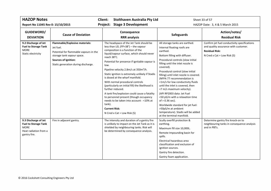
HAZOP Notes Client: Stolthaven Australia Pty Ltd Sheet 33 of 57
Report No 11045 Rev 0: 15/10/2015 Project: Stage 3 Development HAZOP Date: 3, 4 & 5 March 2015
GUIDEWORD/
DEVIATION
Cause of Deviation
Consequence
RRR analysis
Safeguards
Action/notes/
Residual Risk
© 2016 Cockshott Consulting Engineers Pty Ltd
9.2 Discharge of Jet Fuel to Storage Tank MORE Static electricity
Flammable/Explosive materials:
Jet fuel.
Potential for flammable vapours in the storage tank vapour space.
Sources of Ignition:
Static generation during discharge.
The headspace of the Jet Tank should be less than LEL (FP>38°) – the vapour composition is a function of the liquid/vapour surface, which should never reach 38°C.
Potential for presence if ignitable vapour is low.
Pipeline velocity 2.8m/s at 350m3/h.
Static ignition is extremely unlikely if Stadis is dosed at the wharf manifold.
With normal procedural controls (particularly on initial fill) the likelihood is further reduced.
A tank fire/explosion could cause a fatality to personnel present (though occupancy needs to be taken into account ‐ <10% at tank).
Current Risk:
N Cred x Cat = Low Risk (S)
All storage tanks are earthed.
Internal floating roofs are earthed.
Bottom filling with diffuser.
Procedural controls (slow initial filling until the inlet nozzle is covered).
Procedural control (slow initial filling) until inlet nozzle is covered. (NFPA 77 recommendation is <1m/s for low conductivity fluids until the inlet is covered, then <7 m/s maximum velocity).
(API RP2003 data: Jet Fuel <50 pS/m with a relaxation time of > 0.36 sec).
Worldwide standard for jet fuel: >50pS/m at ambient temperature). Stadis will be added at the terminal manifold.
Confirm jet fuel conductivity specifications and quality assurance with customer.
Residual Risk:
N Cred x Cat = Low Risk (S)
9.3 Discharge of Jet Fuel to Storage Tank MORE Heat radiation from a gantry fire.
Fire in adjacent gantry. The intensity and duration of a gantry fire is unlikely to impact on the Jet Tank as it is shielded by neighbouring tanks. Risk will be determined by consequence analysis.
Scully overfill protection & earthing.
Maximum fill size 10,000L.
Remote Impounding basin for spills.
Electrical hazardous area classification and exclusion of ignition sources.
Gantry fire detection.
Gantry foam application.
Determine gantry fire knock‐on to neighbouring tanks in consequence analysis and in PBTs.
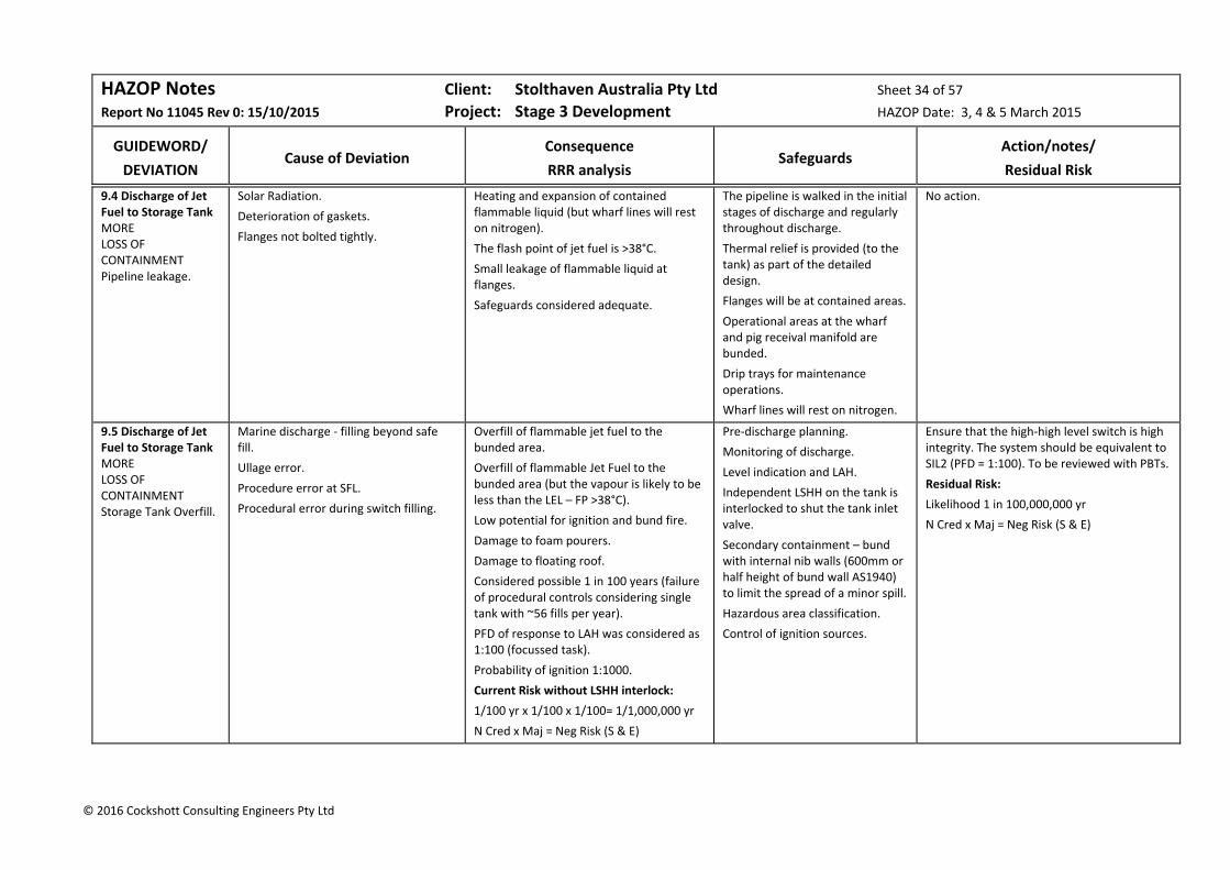
HAZOP Notes Client: Stolthaven Australia Pty Ltd Sheet 34 of 57
Report No 11045 Rev 0: 15/10/2015 Project: Stage 3 Development HAZOP Date: 3, 4 & 5 March 2015
GUIDEWORD/
DEVIATION
Cause of Deviation
Consequence
RRR analysis
Safeguards
Action/notes/
Residual Risk
© 2016 Cockshott Consulting Engineers Pty Ltd
9.4 Discharge of Jet Fuel to Storage Tank MORE LOSS OF CONTAINMENT Pipeline leakage.
Solar Radiation.
Deterioration of gaskets.
Flanges not bolted tightly.
Heating and expansion of contained flammable liquid (but wharf lines will rest on nitrogen).
The flash point of jet fuel is >38°C.
Small leakage of flammable liquid at flanges.
Safeguards considered adequate.
The pipeline is walked in the initial stages of discharge and regularly throughout discharge.
Thermal relief is provided (to the tank) as part of the detailed design.
Flanges will be at contained areas.
Operational areas at the wharf and pig receival manifold are bunded.
Drip trays for maintenance operations.
Wharf lines will rest on nitrogen.
No action.
9.5 Discharge of Jet Fuel to Storage Tank MORE LOSS OF CONTAINMENT Storage Tank Overfill.
Marine discharge ‐ filling beyond safe fill.
Ullage error.
Procedure error at SFL.
Procedural error during switch filling.
Overfill of flammable jet fuel to the bunded area.
Overfill of flammable Jet Fuel to the bunded area (but the vapour is likely to be less than the LEL – FP >38°C).
Low potential for ignition and bund fire.
Damage to foam pourers.
Damage to floating roof.
Considered possible 1 in 100 years (failure of procedural controls considering single tank with ~56 fills per year).
PFD of response to LAH was considered as 1:100 (focussed task).
Probability of ignition 1:1000.
Current Risk without LSHH interlock:
1/100 yr x 1/100 x 1/100= 1/1,000,000 yr
N Cred x Maj = Neg Risk (S & E)
Pre‐discharge planning.
Monitoring of discharge.
Level indication and LAH.
Independent LSHH on the tank is interlocked to shut the tank inlet valve.
Secondary containment – bund with internal nib walls (600mm or half height of bund wall AS1940) to limit the spread of a minor spill.
Hazardous area classification.
Control of ignition sources.
Ensure that the high‐high level switch is high integrity. The system should be equivalent to SIL2 (PFD = 1:100). To be reviewed with PBTs.
Residual Risk:
Likelihood 1 in 100,000,000 yr
N Cred x Maj = Neg Risk (S & E)

HAZOP Notes Client: Stolthaven Australia Pty Ltd Sheet 35 of 57
Report No 11045 Rev 0: 15/10/2015 Project: Stage 3 Development HAZOP Date: 3, 4 & 5 March 2015
GUIDEWORD/
DEVIATION
Cause of Deviation
Consequence
RRR analysis
Safeguards
Action/notes/
Residual Risk
© 2016 Cockshott Consulting Engineers Pty Ltd
9.6 Discharge of Jet Fuel to Storage Tank OTHER EXTERNAL IMPACTS Vehicle impact.
Impact of vehicles with pipeline structural supports.
Pipeline rupture.
Loss of containment to the marine or soil environment.
Safeguards considered adequate.
Site security (gatehouse).
Protection of structural supports.
The pipebridge towers will be placed to avoid proximity to traffic.
The pipelines over the pipebridge will not rest on product.
No action.
9.7 Discharge of Jet Fuel to Storage Tank MORE High pressure ‐ surge
Tank valve slammed shut (ESD).
Ships pumps are stopped.
Manual valves closed.
Emergency release from loading arm coupling.
Potential surge pressures caused by sudden shutoff of downstream (water hammer) or upstream valve (which results in a pocket of vapour and a reverse surge as it collapses).
Loss of containment of minor quantity of flammable material.
All automated valves will close over a period determined by surge modelling.
Manual valves will take about a minute to fully close.
The design pressure of piping is 19.6 bar.
Drip trays.
No action.
9.8 Discharge of Jet Fuel to Storage Tank MORE Overpressure from ammonium nitrate explosion in port or heat radiation from coal carrier at berth in the channel.
Combustible/Explosive materials:
K2 Berth: bulk ammonium nitrate (2 km).
M4 Berth: packaged ammonium nitrate (1 km).
Coal Bulk Carriers (200m from M7).
Sources of Ignition:
On‐board fire on ammonium nitrate ship at K2;
Contamination of ammonium nitrate with organic materials;
Coal fire in Coal bulk carrier hold.
Blast impact from bulk or packaged ammonium nitrate explosion.
Based on the results of consequence analysis, the impact of an ammonium nitrate explosion at K2 to personnel and assets at M7 was considered to be minor.
Based on the results of consequence analysis, the impact of a bulk carrier coal fire across the channel to personnel and assets at M7 was considered to be insignificant.
A knock‐on scenario involving release of alcohol fuels was considered non‐credible.
Current Risk:
E Rare x Min = Neg Risk (S)
External event which is not controlled by Stolthaven.
No further action (See Action 1.8).
Residual Risk:
E Rare x Min = Neg Risk (S)

HAZOP Notes Client: Stolthaven Australia Pty Ltd Sheet 36 of 57
Report No 11045 Rev 0: 15/10/2015 Project: Stage 3 Development HAZOP Date: 3, 4 & 5 March 2015
GUIDEWORD/
DEVIATION
Cause of Deviation
Consequence
RRR analysis
Safeguards
Action/notes/
Residual Risk
© 2016 Cockshott Consulting Engineers Pty Ltd
9.9 Discharge of Jet Fuel to Storage Tank MORE Heat radiation at the wharf from a tank fire at the Terminal.
Fire at the Newcastle Bulk Liquids Terminal.
No development of Lot 1 is included in the Stage 3 Development.
Jet Tank top fire with heat radiation effects at the wharf.
Based on the results of consequence analysis, a tank‐top fire in Lot 36 has no impact to personnel or wharf assets.
Safeguards considered adequate.
Terminal fire detection and protection in accordance with AS1940 and Fire Safety Study.
Terminal Hot Work Permit procedures, exclusion of ignition sources and compliance with Hazardous Area Classification.
Based on previous studies, the risk of a tank top fire is extremely rare, but this will need to be confirmed for the ultimate design.
No action.
Residual Risk:
E Rare x Insig = Neg Risk (S)
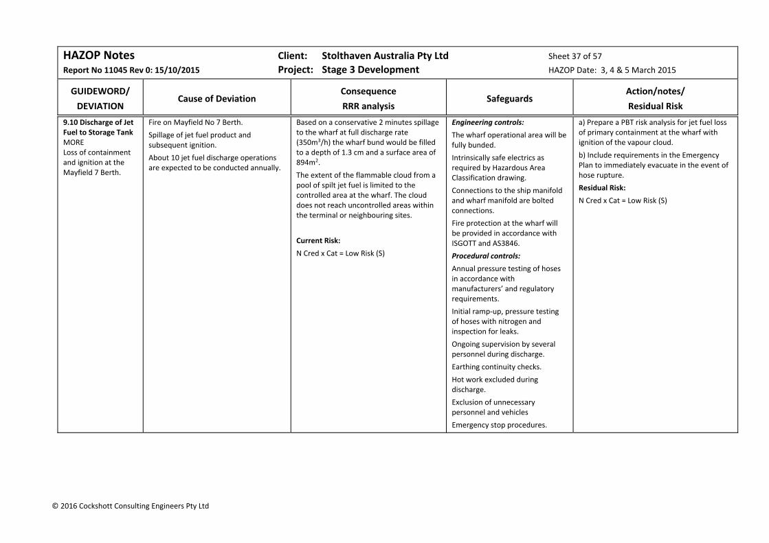
HAZOP Notes Client: Stolthaven Australia Pty Ltd Sheet 37 of 57
Report No 11045 Rev 0: 15/10/2015 Project: Stage 3 Development HAZOP Date: 3, 4 & 5 March 2015
GUIDEWORD/
DEVIATION
Cause of Deviation
Consequence
RRR analysis
Safeguards
Action/notes/
Residual Risk
© 2016 Cockshott Consulting Engineers Pty Ltd
9.10 Discharge of Jet Fuel to Storage Tank MORE Loss of containment and ignition at the Mayfield 7 Berth.
Fire on Mayfield No 7 Berth.
Spillage of jet fuel product and subsequent ignition.
About 10 jet fuel discharge operations are expected to be conducted annually.
Based on a conservative 2 minutes spillage to the wharf at full discharge rate (350m3/h) the wharf bund would be filled to a depth of 1.3 cm and a surface area of 894m2.
The extent of the flammable cloud from a pool of spilt jet fuel is limited to the controlled area at the wharf. The cloud does not reach uncontrolled areas within the terminal or neighbouring sites.
Current Risk:
N Cred x Cat = Low Risk (S)
Engineering controls:
The wharf operational area will be fully bunded.
Intrinsically safe electrics as required by Hazardous Area Classification drawing.
Connections to the ship manifold and wharf manifold are bolted connections.
Fire protection at the wharf will be provided in accordance with ISGOTT and AS3846.
Procedural controls:
Annual pressure testing of hoses in accordance with manufacturers’ and regulatory requirements.
Initial ramp‐up, pressure testing of hoses with nitrogen and inspection for leaks.
Ongoing supervision by several personnel during discharge.
Earthing continuity checks.
Hot work excluded during discharge.
Exclusion of unnecessary personnel and vehicles
Emergency stop procedures.
a) Prepare a PBT risk analysis for jet fuel loss of primary containment at the wharf with ignition of the vapour cloud.
b) Include requirements in the Emergency Plan to immediately evacuate in the event of hose rupture.
Residual Risk:
N Cred x Cat = Low Risk (S)
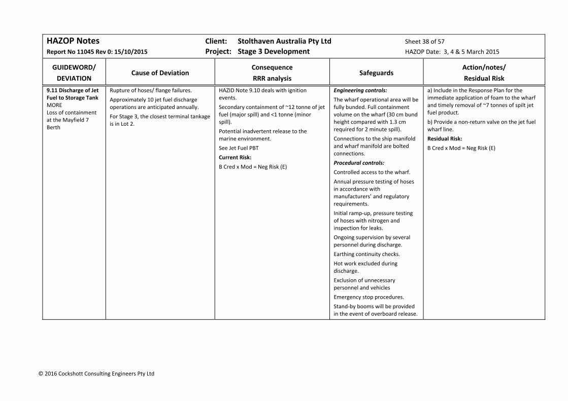
HAZOP Notes Client: Stolthaven Australia Pty Ltd Sheet 38 of 57
Report No 11045 Rev 0: 15/10/2015 Project: Stage 3 Development HAZOP Date: 3, 4 & 5 March 2015
GUIDEWORD/
DEVIATION
Cause of Deviation
Consequence
RRR analysis
Safeguards
Action/notes/
Residual Risk
© 2016 Cockshott Consulting Engineers Pty Ltd
9.11 Discharge of Jet Fuel to Storage Tank MORE Loss of containment at the Mayfield 7 Berth
Rupture of hoses/ flange failures.
Approximately 10 jet fuel discharge operations are anticipated annually.
For Stage 3, the closest terminal tankage is in Lot 2.
HAZID Note 9.10 deals with ignition events.
Secondary containment of ~12 tonne of jet fuel (major spill) and <1 tonne (minor spill).
Potential inadvertent release to the marine environment.
See Jet Fuel PBT
Current Risk:
B Cred x Mod = Neg Risk (E)
Engineering controls:
The wharf operational area will be fully bunded. Full containment volume on the wharf (30 cm bund height compared with 1.3 cm required for 2 minute spill).
Connections to the ship manifold and wharf manifold are bolted connections.
Procedural controls:
Controlled access to the wharf.
Annual pressure testing of hoses in accordance with manufacturers’ and regulatory requirements.
Initial ramp‐up, pressure testing of hoses with nitrogen and inspection for leaks.
Ongoing supervision by several personnel during discharge.
Earthing continuity checks.
Hot work excluded during discharge.
Exclusion of unnecessary personnel and vehicles
Emergency stop procedures.
Stand‐by booms will be provided in the event of overboard release.
a) Include in the Response Plan for the immediate application of foam to the wharf and timely removal of ~7 tonnes of spilt jet fuel product.
b) Provide a non‐return valve on the jet fuel wharf line.
Residual Risk:
B Cred x Mod = Neg Risk (E)
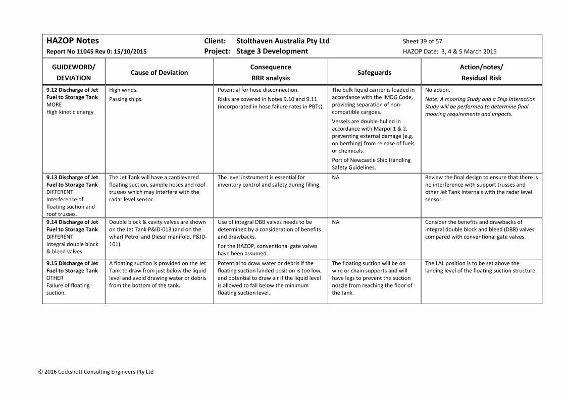
HAZOP Notes Client: Stolthaven Australia Pty Ltd Sheet 39 of 57
Report No 11045 Rev 0: 15/10/2015 Project: Stage 3 Development HAZOP Date: 3, 4 & 5 March 2015
GUIDEWORD/
DEVIATION
Cause of Deviation
Consequence
RRR analysis
Safeguards
Action/notes/
Residual Risk
© 2016 Cockshott Consulting Engineers Pty Ltd
9.12 Discharge of Jet Fuel to Storage Tank MORE High kinetic energy
High winds.
Passing ships.
Potential for hose disconnection.
Risks are covered in Notes 9.10 and 9.11 (incorporated in hose failure rates in PBTs).
The bulk liquid carrier is loaded in accordance with the IMDG Code, providing separation of non‐compatible cargoes.
Vessels are double‐hulled in accordance with Marpol 1 & 2, preventing external damage (e.g. on berthing) from release of fuels or chemicals.
Port of Newcastle Ship Handling Safety Guidelines.
No action.
Note: A mooring Study and a Ship Interaction Study will be performed to determine final mooring requirements and impacts.
9.13 Discharge of Jet Fuel to Storage Tank DIFFERENT Interference of floating suction and roof trusses.
The Jet Tank will have a cantilevered floating suction, sample hoses and roof trusses which may interfere with the radar level sensor.
The level instrument is essential for inventory control and safety during filling.
NA Review the final design to ensure that there is no interference with support trusses and other Jet Tank internals with the radar level sensor.
9.14 Discharge of Jet Fuel to Storage Tank DIFFERENT Integral double block & bleed valves.
Double block & cavity valves are shown on the Jet Tank P&ID‐013 (and on the wharf Petrol and Diesel manifold, P&ID‐101).
Use of integral DBB valves needs to be determined by a consideration of benefits and drawbacks.
For the HAZOP, conventional gate valves have been assumed.
NA Consider the benefits and drawbacks of integral double block and bleed (DBB) valves compared with conventional gate valves.
9.15 Discharge of Jet Fuel to Storage Tank OTHER Failure of floating suction.
A floating suction is provided on the Jet Tank to draw from just below the liquid level and avoid drawing water or debris from the bottom of the tank.
Potential to draw water or debris if the floating suction landed position is too low, and potential to draw air if the liquid level is allowed to fall below the minimum floating suction level.
The floating suction will be on wire or chain supports and will have legs to prevent the suction nozzle from reaching the floor of the tank.
The LAL position is to be set above the landing level of the floating suction structure.
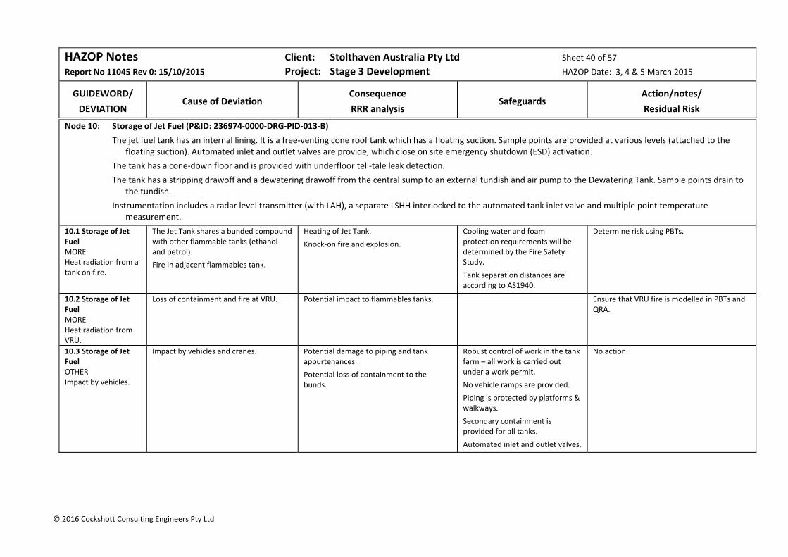
HAZOP Notes Client: Stolthaven Australia Pty Ltd Sheet 40 of 57
Report No 11045 Rev 0: 15/10/2015 Project: Stage 3 Development HAZOP Date: 3, 4 & 5 March 2015
GUIDEWORD/
DEVIATION
Cause of Deviation
Consequence
RRR analysis
Safeguards
Action/notes/
Residual Risk
© 2016 Cockshott Consulting Engineers Pty Ltd
Node 10: Storage of Jet Fuel (P&ID: 236974‐0000‐DRG‐PID‐013‐B)
The jet fuel tank has an internal lining. It is a free‐venting cone roof tank which has a floating suction. Sample points are provided at various levels (attached to the floating suction). Automated inlet and outlet valves are provide, which close on site emergency shutdown (ESD) activation.
The tank has a cone‐down floor and is provided with underfloor tell‐tale leak detection.
The tank has a stripping drawoff and a dewatering drawoff from the central sump to an external tundish and air pump to the Dewatering Tank. Sample points drain to the tundish.
Instrumentation includes a radar level transmitter (with LAH), a separate LSHH interlocked to the automated tank inlet valve and multiple point temperature measurement.
10.1 Storage of Jet Fuel MORE Heat radiation from a tank on fire.
The Jet Tank shares a bunded compound with other flammable tanks (ethanol and petrol).
Fire in adjacent flammables tank.
Heating of Jet Tank.
Knock‐on fire and explosion.
Cooling water and foam protection requirements will be determined by the Fire Safety Study.
Tank separation distances are according to AS1940.
Determine risk using PBTs.
10.2 Storage of Jet Fuel MORE Heat radiation from VRU.
Loss of containment and fire at VRU. Potential impact to flammables tanks. Ensure that VRU fire is modelled in PBTs and QRA.
10.3 Storage of Jet Fuel OTHER Impact by vehicles.
Impact by vehicles and cranes. Potential damage to piping and tank appurtenances.
Potential loss of containment to the bunds.
Robust control of work in the tank farm – all work is carried out under a work permit.
No vehicle ramps are provided.
Piping is protected by platforms & walkways.
Secondary containment is provided for all tanks.
Automated inlet and outlet valves.
No action.

HAZOP Notes Client: Stolthaven Australia Pty Ltd Sheet 41 of 57
Report No 11045 Rev 0: 15/10/2015 Project: Stage 3 Development HAZOP Date: 3, 4 & 5 March 2015
GUIDEWORD/
DEVIATION
Cause of Deviation
Consequence
RRR analysis
Safeguards
Action/notes/
Residual Risk
© 2016 Cockshott Consulting Engineers Pty Ltd
10.4 Storage of Jet Fuel OTHER Weather ‐ earthquakes and soil movement.
Earthquakes and soil movement. Potential damage to associated piping.
Potential loss of containment to the bunds.
Tanks and foundations are to be designed to standards appropriate to the location.
Nozzles are reinforced.
Secondary containment is provided for all tanks.
No action.
10.5 Storage of Jet Fuel MORE LOSS OF CONTAINMENT Tank breathing.
Discharge of flammable vapours from the vented shell.
It is anticipated that vapour discharge to atmosphere will be low due to the low volatility of jet fuel product.
Jet fuel has an inherently low vapour pressure <0.1 kPa).
Review emissions rates for cone roof tanks.
10.6 Storage of Jet Fuel MORE LOSS OF CONTAINMENT Dewatering.
Operator diversion during dewatering operations.
Discharge of product into the bunded area.
Potential for a flammable liquid pool around the dewatering outlet.
Dewatering is a manual operation and procedures will require continuous attendance during dewatering operations.
A dead‐man handle will be provided on the tank dewatering valve.
Secondary containment provided by impermeable bunds.
Electrical hazardous area zoning.
Exclusion of ignition sources.
No action.
10.7 Storage of Jet Fuel MORE Venting of tank vapours
There is low potential for flammable vapours in the storage tank vapour space (FP >38°C).
Potential Sources of Ignition:
Lightning
Hot work
The concentration of vapours in the head space of the Jet Tank is likely to be below the lower flammability limit.
Current Risk:
N Cred x Cat = Low Risk (S)
Hot work permit system.
Maximum storage temperatures (Newcastle, historic figures) 25°C
Review the need for a flame arrestor on the tank free vent in accordance with AS 1940 2004 5.4.5.
Residual Risk:
N Cred x Cat = Low Risk (S)

HAZOP Notes Client: Stolthaven Australia Pty Ltd Sheet 42 of 57
Report No 11045 Rev 0: 15/10/2015 Project: Stage 3 Development HAZOP Date: 3, 4 & 5 March 2015
GUIDEWORD/
DEVIATION
Cause of Deviation
Consequence
RRR analysis
Safeguards
Action/notes/
Residual Risk
© 2016 Cockshott Consulting Engineers Pty Ltd
10.8 Storage of Jet Fuel OTHER EQUIPMENT BREAKDOWN Failure of automated product valves.
Valve actuation failure. The actuated product inlet and outlet valves are a key component of the ESD system. Failure would render overfill protection void.
Product inlet and outlet valves are fail‐to‐close.
Manual tank isolation valves are provided on the product inlet and outlet lines.
a) Establish a test regime for the actuated product inlet and outlet valves.
b) Ensure that a test button is provided to test actuation of the valve ram.
Node 11: Jet Fuel Loadout (PIDs: 236974‐0000‐DRG‐ PID‐13‐B, ‐203‐B, ‐302B & ‐404‐B)
A single duty pump (with standby) provides for loading jet fuel to the southern gantry, Bay 4.
The tank has a floating suction with provision for sampling at different levels below the suction.
The tank has a low level drawoff and a stripping drawoff from the central sump.
The pump is capable of serving a single loading arm (2,500 LPM). Vapours are directed from the gantry to the Vapour Recovery Unit (VRU)
The gantry, which will operate 24/7 is roofed, has protective bollards, fire detection and foam deluge.
11.1 Jet Fuel Loadout NONE No circulation line for dosing.
No provision is made to recirculate the Jet Tank.
Inability to dose with additive in the storage tank if required.
Provide a connection from the loading pump discharge manifold to the inlet line.
11.2 Jet Fuel Loadout NONE No flow to the loading bay.
Line‐up issue.
Blocked coalescer.
If the coalescer becomes blocked, it may take half a day to replace the coalescer elements.
Standby Jet pump is provided.
Line‐up will be confirmed by the fuels management system.
Daily draining of jet fuel coalescer (closed bucket discharged to truck bay slops header).
a) Provide a differential pressure measurement across the Jet filter and readout close to the loading bay.
b) Remove the LS and FSL shown on the P&ID.
11.3 Jet Fuel Loadout MORE LOSS OF CONTAINMENT Leaks in pump bays
Pump seal failure.
Spray of flammable jet fuel.
Escalation of seal/flange fire to other pumps and piping flanges.
The electrical hazardous area classifications will take into account all flanges and pump seals.
Provide fire detection and protection in the pump bays.

HAZOP Notes Client: Stolthaven Australia Pty Ltd Sheet 43 of 57
Report No 11045 Rev 0: 15/10/2015 Project: Stage 3 Development HAZOP Date: 3, 4 & 5 March 2015
GUIDEWORD/
DEVIATION
Cause of Deviation
Consequence
RRR analysis
Safeguards
Action/notes/
Residual Risk
© 2016 Cockshott Consulting Engineers Pty Ltd
11.4 Jet Fuel Loadout MORE MORE Static electricity/electrical spark.
Flammable atmosphere above jet fuel.
Static electricity (piping & coalescer).
Electrical spark.
Potential for a vapour fire in the vapour space of the road tanker.
Pipe velocities based on 2,500 Lpm:
150 mm: 2.0 m/s For non‐conductive liquids, the following velocity limits should be applied (AS 1020):
150 mm: 3.0 m/s Given the high delivered conductivity of Australian jet fuel, the low velocity compared with AS 10120 limits, and the high flash point ‐
Current Risk:
N Cred x Cat = Low Risk (S)
Scully overfill protection & earthing.
Bottom loading.
Ramp pup of loading rate.
(API RP2003 data: Jet Fuel <50 pS/m with a relaxation time of > 0.36 sec).
Worldwide standard for jet fuel: >50pS/m at ambient temperature). Stadis will be added at the terminal manifold.
a) Confirm jet fuel conductivity specifications and quality assurance with customers.
c) Confirm coalescer details and requirements for delivery residence time downstream of the coalescer.
Residual Risk:
N Cred x Cat = Low Risk (S)
11.5 Jet Fuel Loadout MORE Heat radiation from a gantry fire.
Overfill of truck and ignition of spill.
Static from splashing or driver.
Ignition by lightning.
Spark ignition by faulty electrical components.
With current safeguards, an ignited spill in the truck loading bay was considered remote and if it were to happen, then it would be of short duration.
Electrical hazardous area classification.
Exclusion of ignition sources and work permit procedures for all hot work.
Fire detection.
Fire fighting foam deluge system.
Remote impounding basin.
Ensure that electrical installation checks are made as part of the Stolthaven commissioning process.
11.6 Jet Fuel Loadout MORE Heat radiation from a tank on fire adjacent to the gantry.
Tank on fire. Heat radiation to personnel and road tanker.
Potential for vapour generation from the road tanker which will be directed to the VRU (before the road tanker PRV relieves).
Gantry fire detection.
Foam deluge (low & mid level) to gantry bays.
Site evacuation procedures.
No action.
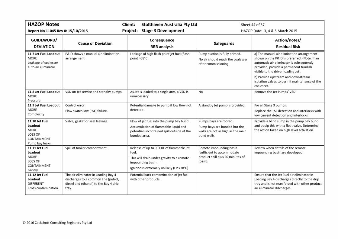
HAZOP Notes Client: Stolthaven Australia Pty Ltd Sheet 44 of 57
Report No 11045 Rev 0: 15/10/2015 Project: Stage 3 Development HAZOP Date: 3, 4 & 5 March 2015
GUIDEWORD/
DEVIATION
Cause of Deviation
Consequence
RRR analysis
Safeguards
Action/notes/
Residual Risk
© 2016 Cockshott Consulting Engineers Pty Ltd
11.7 Jet Fuel Loadout MORE Leakage of coalescer auto air eliminator.
P&ID shows a manual air elimination arrangement.
Leakage of high flash point jet fuel (flash point >38°C).
Pump suction is fully primed.
No air should reach the coalescer after commissioning.
a) The manual air elimination arrangement shown on the P&ID is preferred. (Note: If an automatic air eliminator is subsequently provided, provide a permanent tundish visible to the driver loading Jet).
b) Provide upstream and downstream isolation valves to permit maintenance of the coalescer.
11.8 Jet Fuel Loadout MORE Pressure
VSD on Jet service and standby pumps. As Jet is loaded to a single arm, a VSD is unnecessary.
NA Remove the Jet Pumps’ VSD.
11.9 Jet Fuel Loadout MORE Complexity
Control error.
Flow switch low (FSL) failure.
Potential damage to pump if low flow not detected.
A standby Jet pump is provided. For all Stage 3 pumps:
Replace the FSL detection and interlocks with low current detection and interlocks.
11.10 Jet Fuel Loadout MORE LOSS OF CONTAINMENT Pump bay leaks..
Valve, gasket or seal leakage. Flow of jet fuel into the pump bay bund.
Accumulation of flammable liquid and potential uncontained spill outside of the bunded area.
Pumps bays are roofed.
Pump bays are bunded but the walls are not as high as the main bund walls.
Provide a blind sump in the pump bay bund and equip this with a float valve. Determine the action taken on high level activation.
11.11 Jet Fuel Loadout MORE LOSS OF CONTAINMENT Gantry
Spill of tanker compartment. Release of up to 9,000L of flammable jet fuel.
This will drain under gravity to a remote impounding basin.
Ignition is extremely unlikely (FP >38°C)
Remote impounding basin (sufficient to accommodate product spill plus 20 minutes of foam).
Review when details of the remote impounding basin are developed.
11.12 Jet Fuel Loadout DIFFERENT Cross contamination.
The air eliminator in Loading Bay 4 discharges to a common line (petrol, diesel and ethanol) to the Bay 4 drip tray.
Potential back contamination of jet fuel with other products.
Ensure that the Jet Fuel air eliminator in Loading Bay 4 discharges directly to the drip tray and is not manifolded with other product air eliminator discharges.
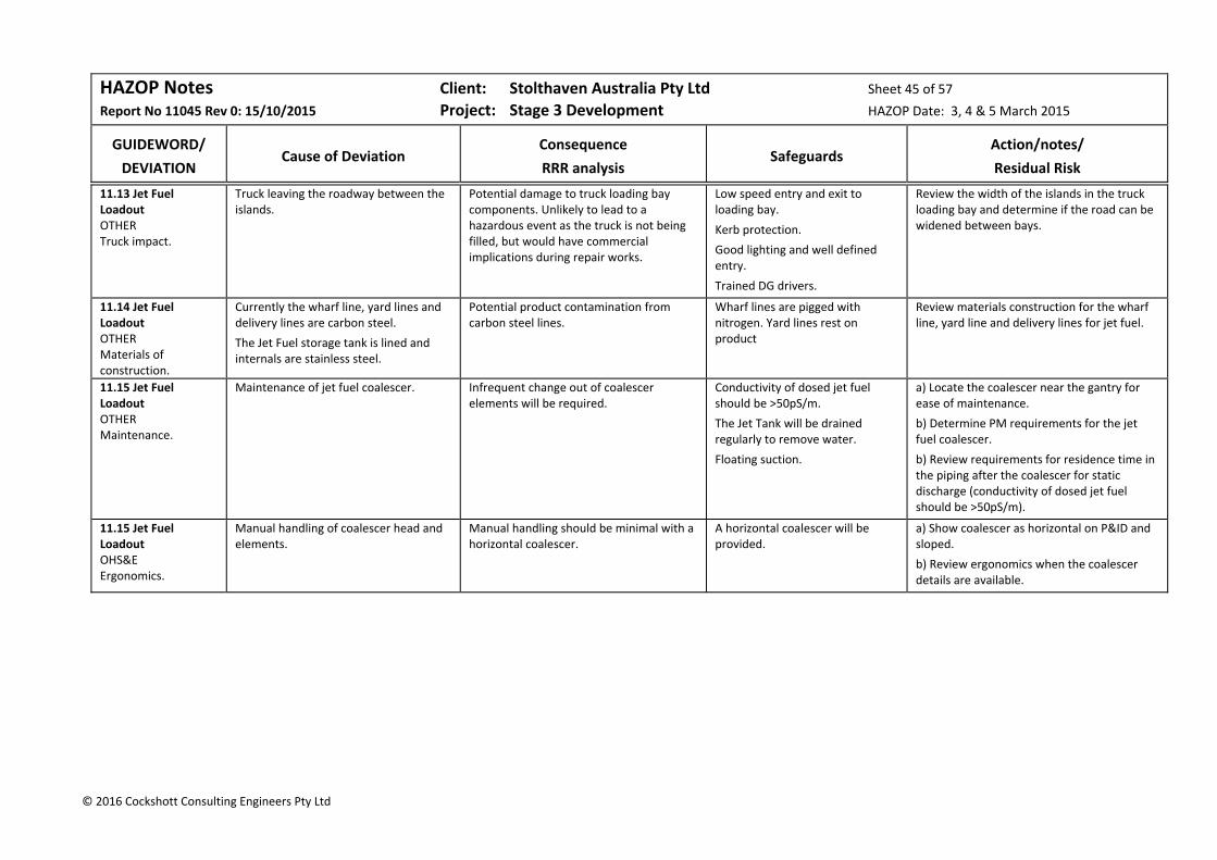
HAZOP Notes Client: Stolthaven Australia Pty Ltd Sheet 45 of 57
Report No 11045 Rev 0: 15/10/2015 Project: Stage 3 Development HAZOP Date: 3, 4 & 5 March 2015
GUIDEWORD/
DEVIATION
Cause of Deviation
Consequence
RRR analysis
Safeguards
Action/notes/
Residual Risk
© 2016 Cockshott Consulting Engineers Pty Ltd
11.13 Jet Fuel Loadout OTHER Truck impact.
Truck leaving the roadway between the islands.
Potential damage to truck loading bay components. Unlikely to lead to a hazardous event as the truck is not being filled, but would have commercial implications during repair works.
Low speed entry and exit to loading bay.
Kerb protection.
Good lighting and well defined entry.
Trained DG drivers.
Review the width of the islands in the truck loading bay and determine if the road can be widened between bays.
11.14 Jet Fuel Loadout OTHER Materials of construction.
Currently the wharf line, yard lines and delivery lines are carbon steel.
The Jet Fuel storage tank is lined and internals are stainless steel.
Potential product contamination from carbon steel lines.
Wharf lines are pigged with nitrogen. Yard lines rest on product
Review materials construction for the wharf line, yard line and delivery lines for jet fuel.
11.15 Jet Fuel Loadout OTHER Maintenance.
Maintenance of jet fuel coalescer. Infrequent change out of coalescer elements will be required.
Conductivity of dosed jet fuel should be >50pS/m.
The Jet Tank will be drained regularly to remove water.
Floating suction.
a) Locate the coalescer near the gantry for ease of maintenance.
b) Determine PM requirements for the jet fuel coalescer.
b) Review requirements for residence time in the piping after the coalescer for static discharge (conductivity of dosed jet fuel should be >50pS/m).
11.15 Jet Fuel Loadout OHS&E Ergonomics.
Manual handling of coalescer head and elements.
Manual handling should be minimal with a horizontal coalescer.
A horizontal coalescer will be provided.
a) Show coalescer as horizontal on P&ID and sloped.
b) Review ergonomics when the coalescer details are available.

HAZOP Notes Client: Stolthaven Australia Pty Ltd Sheet 46 of 57
Report No 11045 Rev 0: 15/10/2015 Project: Stage 3 Development HAZOP Date: 3, 4 & 5 March 2015
GUIDEWORD/
DEVIATION
Cause of Deviation
Consequence
RRR analysis
Safeguards
Action/notes/
Residual Risk
© 2016 Cockshott Consulting Engineers Pty Ltd
Node 12: Marine Discharge of Ethanol to Storage Tank (P&IDs: 236974‐0000‐DRG‐‐P&ID‐101‐B, 104‐B & 012‐B)
A single dedicated 200mm carbon steel ethanol wharf line (~440m length) is provided from the wharf to the pig stations in Lot 36.
Ethanol has a lower vapour pressure than gasoline (~8 kPa vs 62‐80 kPa) and has a flash point of 9°C. The discharge rate for the ethanol is 350m3/h.
A single 200mm yard line is connected from the pig receiver to Tank T25.
With a discharge rate through the wharf line of 350m3/h, the fluid velocity is 3.0m/s.
The ethanol tank has automated inlet and outlet valves which close on site emergency shutdown (ESD) activation. The tank inlet is provided with a diffuser.
The P&ID shows an Internal Floating Roof (IFR) tank with recirculation. For the HAZOP, it was agreed that the tank is most likely to be a low pressure (API 620 Appendix F) to minimise loss to the air environment. The recirculation line will be deleted.
Each tank has a cone‐down floor and is provided with tell‐tale leak detection.
Instrumentation will include a pressure control valve for vapours, a relief valve and an emergency vent, a radar level transmitter (LAH), separate LSHH interlocked to the tank inlet valve and multiple point temperature measurement.
Following discharge, wharf piping will be cleared to the VRU and the yard piping will be cleared to the tank. The lines will rest on nitrogen.
The yard piping will rest on product.
12.1 Marine Discharge of Ethanol to Storage MORE Static electricity – wharf lines.
Flammable/Explosive materials:
Ethanol.
Residual vapour in wharf line from the berth to the terminal isolation valve, following pigging to the pig receiver with nitrogen.
Sources of Ignition:
Static generation during discharge;
Lightning.
Static generation is not considered to be an issue with ethanol.
Pipe velocity at 350 m3/h:
Wharf 200mm: 3.0 m/s For non‐conductive liquids, the following velocity limits should be applied (AS 1020):
200mm: 1.8 m/s Given the use of nitrogen for clearing the wharf line, ignition was considered non‐credible:
Current Risk:
N Cred x Maj = Neg Risk (S)
All wharf and yard piping is electrically earthed.
Ethanol is a conductive liquid, >100µS/m.
(AS 1020: “the tendency of lower alcohols to generate static electricity is negligible”).
Slow initial pumping rate with ramp‐up and ramp‐down.
Wharf line cleared with nitrogen.
a) Provide an isolation valve shore‐side on the ethanol line.
b) Review the proposed procedure to remove product from the over‐water section of the ethanol wharf lines. Determine if air or nitrogen is used to clear the wharf line to the terminal valve.
c) If air is used to clear the over‐water lines, determine how this is cleared for the next discharge.
Residual Risk:
N Cred x Maj = Neg Risk (S)
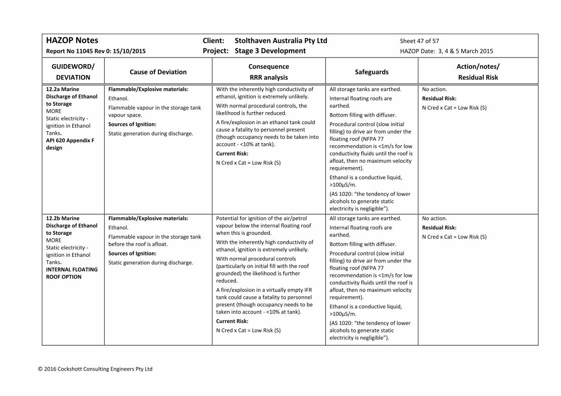
HAZOP Notes Client: Stolthaven Australia Pty Ltd Sheet 47 of 57
Report No 11045 Rev 0: 15/10/2015 Project: Stage 3 Development HAZOP Date: 3, 4 & 5 March 2015
GUIDEWORD/
DEVIATION
Cause of Deviation
Consequence
RRR analysis
Safeguards
Action/notes/
Residual Risk
© 2016 Cockshott Consulting Engineers Pty Ltd
12.2a Marine Discharge of Ethanol to Storage MORE Static electricity ‐ ignition in Ethanol Tanks. API 620 Appendix F design
Flammable/Explosive materials:
Ethanol.
Flammable vapour in the storage tank vapour space.
Sources of Ignition:
Static generation during discharge.
With the inherently high conductivity of ethanol, ignition is extremely unlikely.
With normal procedural controls, the likelihood is further reduced.
A fire/explosion in an ethanol tank could cause a fatality to personnel present (though occupancy needs to be taken into account ‐ <10% at tank).
Current Risk:
N Cred x Cat = Low Risk (S)
All storage tanks are earthed.
Internal floating roofs are earthed.
Bottom filling with diffuser.
Procedural control (slow initial filling) to drive air from under the floating roof (NFPA 77 recommendation is <1m/s for low conductivity fluids until the roof is afloat, then no maximum velocity requirement).
Ethanol is a conductive liquid, >100µS/m.
(AS 1020: “the tendency of lower alcohols to generate static electricity is negligible”).
No action.
Residual Risk:
N Cred x Cat = Low Risk (S)
12.2b Marine Discharge of Ethanol to Storage MORE Static electricity ‐ ignition in Ethanol Tanks. INTERNAL FLOATING ROOF OPTION
Flammable/Explosive materials:
Ethanol.
Flammable vapour in the storage tank before the roof is afloat.
Sources of Ignition:
Static generation during discharge.
Potential for ignition of the air/petrol vapour below the internal floating roof when this is grounded.
With the inherently high conductivity of ethanol, ignition is extremely unlikely.
With normal procedural controls (particularly on initial fill with the roof grounded) the likelihood is further reduced.
A fire/explosion in a virtually empty IFR tank could cause a fatality to personnel present (though occupancy needs to be taken into account ‐ <10% at tank).
Current Risk:
N Cred x Cat = Low Risk (S)
All storage tanks are earthed.
Internal floating roofs are earthed.
Bottom filling with diffuser.
Procedural control (slow initial filling) to drive air from under the floating roof (NFPA 77 recommendation is <1m/s for low conductivity fluids until the roof is afloat, then no maximum velocity requirement).
Ethanol is a conductive liquid, >100µS/m.
(AS 1020: “the tendency of lower alcohols to generate static electricity is negligible”).
No action.
Residual Risk:
N Cred x Cat = Low Risk (S)

HAZOP Notes Client: Stolthaven Australia Pty Ltd Sheet 48 of 57
Report No 11045 Rev 0: 15/10/2015 Project: Stage 3 Development HAZOP Date: 3, 4 & 5 March 2015
GUIDEWORD/
DEVIATION
Cause of Deviation
Consequence
RRR analysis
Safeguards
Action/notes/
Residual Risk
© 2016 Cockshott Consulting Engineers Pty Ltd
12.3 Marine Discharge of Ethanol to Storage MORE Heat radiation from a gantry fire.
Fire in adjacent gantry. The intensity and duration of a gantry fire is unlikely to impact on neighbouring tanks and will be determined by consequence analysis.
Scully overfill protection & earthing.
Maximum fill size 10,000L.
Remote Impounding basin for spills.
Electrical hazardous area classification and exclusion of ignition sources.
Gantry fire detection.
Gantry foam application.
Determine gantry fire knock‐on from the ethanol tank to neighbouring tanks in consequence analysis and in PBTs.
12.4 Marine Discharge of Ethanol to Storage MORE LOSS OF CONTAINMENT Pipeline leakage.
Solar Radiation.
Deterioration of gaskets.
Flanges not bolted tightly.
Heating and expansion of contained flammable liquid (if resting on product).
Small leakage of flammable liquid at flanges.
Safeguards considered adequate.
Thermal relief provided (to tankage) as part of the detailed design.
Flanges will be at contained areas.
Drip trays.
Wharf lines rest on nitrogen between discharges.
No action.
12.5 Marine Discharge of Ethanol to Storage MORE LOSS OF CONTAINMENT Storage Tank Overfill.
Marine discharge ‐ filling beyond safe fill.
Ullage error.
Procedure error at SFL.
Overfill of flammable ethanol to the bunded area.
Potential ignition and bund fire.
Considered possible 1 in 100 years (considering 12 tanks with ~10 fills per year).
PFD of response to LAH was considered as 1:100 (focussed task).
Probability of ignition 1:100.
Current Risk without LSHH interlock:
1/10 yr x 1/100 x 1/100= 1/100,000 yr
N Cred x Maj = Neg Risk (S & E)
Pre‐discharge planning.
Monitoring of discharge.
Level indication and LAH.
High‐high level switches activate ESD system which shuts down tank inlet and outlet valves and raises a general alarm at the wharf and terminal.
Secondary containment – bund with internal nib walls (600mm or half height of bund wall AS1940) to limit the spread of a minor spill.
Hazardous area classification.
Hazardous area classification.
Control of ignition sources.
Include a test for ethanol for water in the sub‐compounds in the ethanol bund.
Residual Risk:
N Cred x Maj = Neg Risk (S & E)

HAZOP Notes Client: Stolthaven Australia Pty Ltd Sheet 49 of 57
Report No 11045 Rev 0: 15/10/2015 Project: Stage 3 Development HAZOP Date: 3, 4 & 5 March 2015
GUIDEWORD/
DEVIATION
Cause of Deviation
Consequence
RRR analysis
Safeguards
Action/notes/
Residual Risk
© 2016 Cockshott Consulting Engineers Pty Ltd
12.6 Marine Discharge of Ethanol to Storage MORE High pressure ‐ surge
Tank valve slammed shut (ESD).
Ships pumps are stopped.
Manual valves closed.
Emergency release from loading arm coupling.
Potential surge pressures caused by sudden shutoff of downstream (water hammer) or upstream valve (which results in a pocket of vapour and a reverse surge as it collapses).
Loss of containment of minor quantity of flammable material.
All automated valves will close over a period determined by surge modelling.
Manual valves will take about a minute to fully close.
The design pressure of piping is 19.5bar.
Drip trays.
No further action.
Action 1.7 applies to the ethanol tank.
12.7 Marine Discharge of Ethanol to Storage MORE Overpressure from ammonium nitrate explosion in port or heat radiation from coal carrier at berth in the channel.
Combustible/Explosive materials:
K2 Berth: bulk ammonium nitrate (2 km).
M4 Berth: packaged ammonium nitrate (1 km).
Coal Bulk Carriers (200m from M7).
Sources of Ignition:
On‐board fire on ammonium nitrate ship at K2;
Contamination of ammonium nitrate with organic materials;
Coal fire in Coal bulk carrier hold.
Blast impact from bulk or packaged ammonium nitrate explosion.
Based on the results of consequence analysis, the impact of an ammonium nitrate explosion at K2 to personnel and assets at M7 was considered to be minor.
Based on the results of consequence analysis, the impact of a bulk coal carrier fire across the channel to personnel and assets at M7 or the terminal was considered to be insignificant.
A knock‐on scenario involving release of petrol was considered non‐credible.
Current Risk:
E Rare x Min = Neg Risk (S)
External event which is not controlled by Stolthaven.
a) Operations should be halted for any event at the Ammonium Nitrate manufacturing facility (e.g. fire or ammonia release) or cargo fire on a bulk coal carrier.
Residual Risk:
E Rare x Min = Neg Risk (S)
12.8 Marine Discharge of Ethanol to Storage MORE Heat radiation at the wharf from a tank fire at the Terminal.
Fire at the Newcastle Bulk Liquids Terminal.
No development of Lot 1 is included in the Stage 3 Development.
Tank top fire with heat radiation effects.
Based on the results of consequence analysis of a fire in Lot 36, a tank‐top fire has no impact to personnel or wharf assets.
Terminal fire detection and protection in accordance with the Fire Safety Study and AS1940.
Terminal Hot Work Permit procedures, exclusion of ignition sources and compliance with Hazardous Area Classification.
No action.

HAZOP Notes Client: Stolthaven Australia Pty Ltd Sheet 50 of 57
Report No 11045 Rev 0: 15/10/2015 Project: Stage 3 Development HAZOP Date: 3, 4 & 5 March 2015
GUIDEWORD/
DEVIATION
Cause of Deviation
Consequence
RRR analysis
Safeguards
Action/notes/
Residual Risk
© 2016 Cockshott Consulting Engineers Pty Ltd
12.9 Marine Discharge of Ethanol to Storage MORE Loss of containment and ignition at the Mayfield 7 Berth.
Spillage of flammable product and subsequent ignition.
Ignition of vapours by non‐rated vehicles or hot work.
About 10 ethanol discharge operations are expected to be conducted annually.
For Stage 3, the closest terminal tankage is in Lot 2.
Fire on Mayfield No 7 Berth.
Based on a conservative 2 minutes spillage to the wharf at full discharge rate (350 m3/h) the wharf bund would be filled to a depth of 1.3cm and surface area of 894m2.
Flash fire at ignition source and ignition of pool fire (after more than 2 minutes) at the wharf.
Current Risk (personnel inside the terminal and at the worst neighbouring location:
N Cred x Cat = Low Risk (S)
Engineering controls:
The wharf operational area will be fully bunded.
Intrinsically safe electrics as required by Hazardous Area Classification drawing.
Connections to the ship manifold and wharf manifold are bolted connections.
Fire protection at the wharf will be provided in accordance with ISGOTT and AS3846.
Procedural controls:
Annual pressure testing of hoses in accordance with manufacturers’ and regulatory requirements.
Initial ramp‐up, pressure testing of hoses with nitrogen and inspection for leaks.
Ongoing supervision by several personnel during discharge.
Earthing continuity checks.
Hot work excluded during discharge.
Exclusion of unnecessary personnel and vehicles
Emergency stop procedures.
a) Prepare a PBT risk analysis for ethanol loss of primary containment at the wharf with ignition of the vapour cloud.
b) Include requirements in the Emergency Plan to immediately evacuate in the event of hose rupture.
Residual Risk:
N Cred x Cat = Low Risk (S)
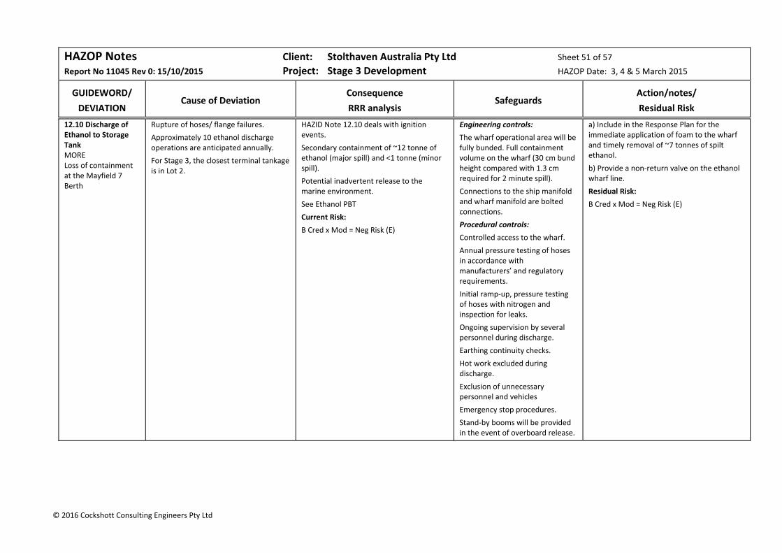
HAZOP Notes Client: Stolthaven Australia Pty Ltd Sheet 51 of 57
Report No 11045 Rev 0: 15/10/2015 Project: Stage 3 Development HAZOP Date: 3, 4 & 5 March 2015
GUIDEWORD/
DEVIATION
Cause of Deviation
Consequence
RRR analysis
Safeguards
Action/notes/
Residual Risk
© 2016 Cockshott Consulting Engineers Pty Ltd
12.10 Discharge of Ethanol to Storage Tank MORE Loss of containment at the Mayfield 7 Berth
Rupture of hoses/ flange failures.
Approximately 10 ethanol discharge operations are anticipated annually.
For Stage 3, the closest terminal tankage is in Lot 2.
HAZID Note 12.10 deals with ignition events.
Secondary containment of ~12 tonne of ethanol (major spill) and <1 tonne (minor spill).
Potential inadvertent release to the marine environment.
See Ethanol PBT
Current Risk:
B Cred x Mod = Neg Risk (E)
Engineering controls:
The wharf operational area will be fully bunded. Full containment volume on the wharf (30 cm bund height compared with 1.3 cm required for 2 minute spill).
Connections to the ship manifold and wharf manifold are bolted connections.
Procedural controls:
Controlled access to the wharf.
Annual pressure testing of hoses in accordance with manufacturers’ and regulatory requirements.
Initial ramp‐up, pressure testing of hoses with nitrogen and inspection for leaks.
Ongoing supervision by several personnel during discharge.
Earthing continuity checks.
Hot work excluded during discharge.
Exclusion of unnecessary personnel and vehicles
Emergency stop procedures.
Stand‐by booms will be provided in the event of overboard release.
a) Include in the Response Plan for the immediate application of foam to the wharf and timely removal of ~7 tonnes of spilt ethanol.
b) Provide a non‐return valve on the ethanol wharf line.
Residual Risk:
B Cred x Mod = Neg Risk (E)
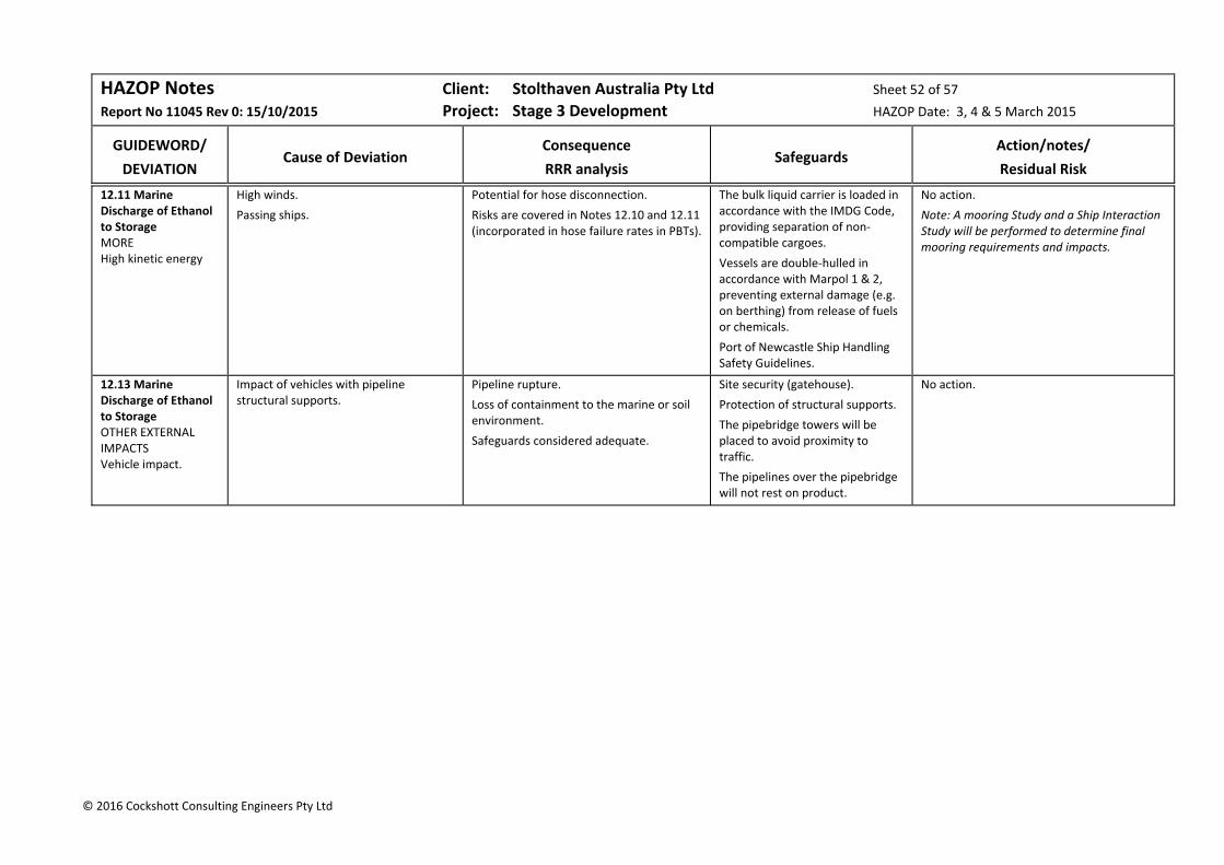
HAZOP Notes Client: Stolthaven Australia Pty Ltd Sheet 52 of 57
Report No 11045 Rev 0: 15/10/2015 Project: Stage 3 Development HAZOP Date: 3, 4 & 5 March 2015
GUIDEWORD/
DEVIATION
Cause of Deviation
Consequence
RRR analysis
Safeguards
Action/notes/
Residual Risk
© 2016 Cockshott Consulting Engineers Pty Ltd
12.11 Marine Discharge of Ethanol to Storage MORE High kinetic energy
High winds.
Passing ships.
Potential for hose disconnection.
Risks are covered in Notes 12.10 and 12.11 (incorporated in hose failure rates in PBTs).
The bulk liquid carrier is loaded in accordance with the IMDG Code, providing separation of non‐compatible cargoes.
Vessels are double‐hulled in accordance with Marpol 1 & 2, preventing external damage (e.g. on berthing) from release of fuels or chemicals.
Port of Newcastle Ship Handling Safety Guidelines.
No action.
Note: A mooring Study and a Ship Interaction Study will be performed to determine final mooring requirements and impacts.
12.13 Marine Discharge of Ethanol to Storage OTHER EXTERNAL IMPACTS Vehicle impact.
Impact of vehicles with pipeline structural supports.
Pipeline rupture.
Loss of containment to the marine or soil environment.
Safeguards considered adequate.
Site security (gatehouse).
Protection of structural supports.
The pipebridge towers will be placed to avoid proximity to traffic.
The pipelines over the pipebridge will not rest on product.
No action.

HAZOP Notes Client: Stolthaven Australia Pty Ltd Sheet 53 of 57
Report No 11045 Rev 0: 15/10/2015 Project: Stage 3 Development HAZOP Date: 3, 4 & 5 March 2015
GUIDEWORD/
DEVIATION
Cause of Deviation
Consequence
RRR analysis
Safeguards
Action/notes/
Residual Risk
© 2016 Cockshott Consulting Engineers Pty Ltd
Node 13: Storage of Ethanol (P&ID: 236974‐0000‐DRG‐PID‐012‐B)
The P&ID shows an Internal Floating Roof (IFR) tank with recirculation. For the HAZOP, it was agreed that the tank is most likely to be a low pressure (API 620 Appendix F) to minimise loss to the air environment. The recirculation line will be deleted. The air scoops are deleted
The dewatering system show on the P&ID has been removed for the purposes of the HAZOP.
The ethanol tank has automated inlet and outlet valves which close on site emergency shutdown (ESD) activation. The inlet valve is interlocked with the LSHH.
The tank is a free‐venting cone roof tank with a cone‐down floor and is provided with underfloor tell‐tale leak detection.
The tank has a stripping drawoff from the central sump.
Instrumentation includes a radar level transmitter (with LAH), a separate LSHH interlocked to the automated tank inlet valve and multiple point temperature measurement.
13.1 Storage of Ethanol MORE Heat radiation from tank‐on‐fire
Fire in adjacent flammables tank. Heating of tank‐at‐risk.
Knock‐on fire and explosion.
Cooling water and foam protection requirements will be determined by the Fire Safety Study.
Tank separation distances are according to AS1940.
Determine risk using PBTs.
13.2 Storage of Ethanol MORE Heat radiation from VRU.
Loss of containment and fire at VRU. Heat radiation impact at the ethanol tank is not feasible.
No action.
13.2 Storage of Ethanol DIFFERENT Emissions to air for IFR and low pressure tanks.
The final decision has not been made as to whether the ethanol tank should be an IFR tank or a low pressure tank.
Further information is needed to make a decision.
Review emissions rates for IFR and low pressure (API 620 Appendix F) cone roof tanks
13.4 Storage of Ethanol DIFFERENT Import by road tanker.
The design only provides for import by ship.
This is a design basis issue. Determine if facilities for road tanker importation should be provided for ethanol.

HAZOP Notes Client: Stolthaven Australia Pty Ltd Sheet 54 of 57
Report No 11045 Rev 0: 15/10/2015 Project: Stage 3 Development HAZOP Date: 3, 4 & 5 March 2015
GUIDEWORD/
DEVIATION
Cause of Deviation
Consequence
RRR analysis
Safeguards
Action/notes/
Residual Risk
© 2016 Cockshott Consulting Engineers Pty Ltd
13.5 Storage of Ethanol OTHER Impact by vehicles
Impact by vehicles and cranes. Potential damage to piping and tank appurtenances.
Potential loss of containment to the bunds.
Robust control of work in the tank farm – all work is carried out under a work permit.
No vehicle ramps are provided.
Piping is protected by platforms & walkways.
Secondary containment is provided for all tanks.
Automated inlet and outlet valves.
No action.
13.6 Storage of Ethanol OTHER Weather ‐ earthquakes and soil movement.
Earthquakes and soil movement. Potential damage to associated piping.
Potential loss of containment to the bunds.
Tanks and foundations are to be designed to standards appropriate to the location.
Nozzles are reinforced.
Secondary containment is provided for all tanks.
No action.
13.7 Storage of Ethanol LOSS OF CONTAINMENT Tank breathing.
Vapours in the ethanol tank will be within explosive limits.
Discharge of flammable vapours from the vented shell.
Potential Sources of Ignition:
Lightning
Hot work
Potential ignition and explosion due to lightning strike during tank breathing conditions.
Rare x Cat = Sig Risk (S)
The flammables tanks are equipped with internal floating roofs to minimise loss to the environment.
Provide a flame arrestor on the free vent of the ethanol tank in accordance with AS 1940 2004 5.4.5.
B Cred x Cat = Low Risk (S)
13.8 Storage of Ethanol EQUIPMENT BREAKDOWN Failure of automated product valves.
Valve actuation failure. The actuated product inlet and outlet valves are a key component of the ESD system. Failure would render overfill protection void.
Product inlet and outlet valves are fail‐to‐close.
Manual tank isolation valves are provided on the product inlet and outlet lines.
a) Establish a test regime for the actuated product inlet and outlet valves (API 650 Appendix F Design).
b) Ensure that a test button is provided to test actuation of the valve ram.
13.9 Storage of Ethanol OTHER Failure of automated product valves.
Valve actuation failure. The actuated product inlet and outlet valves are a key component of the ESD system. Failure would render overfill protection void.
Product inlet and outlet valves are fail‐to‐close.
Manual tank isolation valves are provided on the product inlet and outlet lines.
Apply Actions 2.13 a/b/c to the ethanol tank.
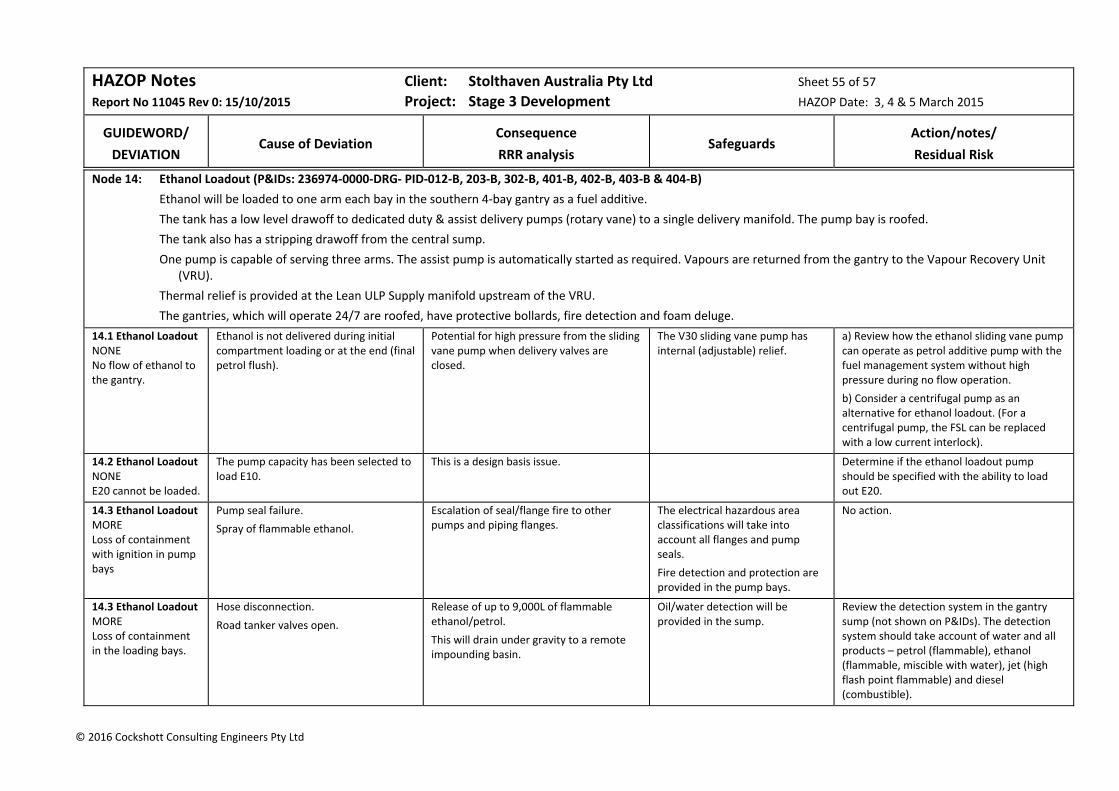
HAZOP Notes Client: Stolthaven Australia Pty Ltd Sheet 55 of 57
Report No 11045 Rev 0: 15/10/2015 Project: Stage 3 Development HAZOP Date: 3, 4 & 5 March 2015
GUIDEWORD/
DEVIATION
Cause of Deviation
Consequence
RRR analysis
Safeguards
Action/notes/
Residual Risk
© 2016 Cockshott Consulting Engineers Pty Ltd
Node 14: Ethanol Loadout (P&IDs: 236974‐0000‐DRG‐ PID‐012‐B, 203‐B, 302‐B, 401‐B, 402‐B, 403‐B & 404‐B)
Ethanol will be loaded to one arm each bay in the southern 4‐bay gantry as a fuel additive.
The tank has a low level drawoff to dedicated duty & assist delivery pumps (rotary vane) to a single delivery manifold. The pump bay is roofed.
The tank also has a stripping drawoff from the central sump.
One pump is capable of serving three arms. The assist pump is automatically started as required. Vapours are returned from the gantry to the Vapour Recovery Unit (VRU).
Thermal relief is provided at the Lean ULP Supply manifold upstream of the VRU.
The gantries, which will operate 24/7 are roofed, have protective bollards, fire detection and foam deluge.
14.1 Ethanol Loadout NONE No flow of ethanol to the gantry.
Ethanol is not delivered during initial compartment loading or at the end (final petrol flush).
Potential for high pressure from the sliding vane pump when delivery valves are closed.
The V30 sliding vane pump has internal (adjustable) relief.
a) Review how the ethanol sliding vane pump can operate as petrol additive pump with the fuel management system without high pressure during no flow operation.
b) Consider a centrifugal pump as an alternative for ethanol loadout. (For a centrifugal pump, the FSL can be replaced with a low current interlock).
14.2 Ethanol Loadout NONE E20 cannot be loaded.
The pump capacity has been selected to load E10.
This is a design basis issue. Determine if the ethanol loadout pump should be specified with the ability to load out E20.
14.3 Ethanol Loadout MORE Loss of containment with ignition in pump bays
Pump seal failure.
Spray of flammable ethanol.
Escalation of seal/flange fire to other pumps and piping flanges.
The electrical hazardous area classifications will take into account all flanges and pump seals.
Fire detection and protection are provided in the pump bays.
No action.
14.3 Ethanol Loadout MORE Loss of containment in the loading bays.
Hose disconnection.
Road tanker valves open.
Release of up to 9,000L of flammable ethanol/petrol.
This will drain under gravity to a remote impounding basin.
Oil/water detection will be provided in the sump.
Review the detection system in the gantry sump (not shown on P&IDs). The detection system should take account of water and all products – petrol (flammable), ethanol (flammable, miscible with water), jet (high flash point flammable) and diesel (combustible).
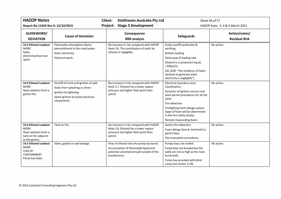
HAZOP Notes Client: Stolthaven Australia Pty Ltd Sheet 56 of 57
Report No 11045 Rev 0: 15/10/2015 Project: Stage 3 Development HAZOP Date: 3, 4 & 5 March 2015
GUIDEWORD/
DEVIATION
Cause of Deviation
Consequence
RRR analysis
Safeguards
Action/notes/
Residual Risk
© 2016 Cockshott Consulting Engineers Pty Ltd
14.2 Ethanol Loadout MORE Static electricity/electrical spark.
Flammable atmosphere above petrol/ethanol in the road tanker.
Static electricity.
Electrical spark.
No increase in risk compared with HAZOP Note 3.6. The contribution of static by ethanol is negligible.
Scully overfill protection & earthing.
Bottom loading.
Ramp pup of loading rate.
Ethanol is a conductive liquid, >100µS/m.
(AS 1020: “the tendency of lower alcohols to generate static electricity is negligible”).
No action.
14.3 Ethanol Loadout MORE Heat radiation from a gantry fire.
Overfill of truck and ignition of spill.
Static from splashing or driver.
Ignition by lightning.
Spark ignition by faulty electrical components.
No increase in risk compared with HAZOP Note 3.7. Ethanol has a lower vapour pressure and higher flash point then petrol.
Electrical hazardous area classification.
Exclusion of ignition sources and work permit procedures for all hot work.
Fire detection.
Firefighting foam deluge system (type of foam will be determined in the Fire Safety Study).
Remote impounding basin.
No action.
14.4 Ethanol Loadout MORE Heat radiation from a tank on fire adjacent to the gantry.
Tank on fire. No increase in risk compared with HAZOP Note 3.8. Ethanol has a lower vapour pressure and higher flash point then petrol.
Gantry fire detection.
Foam deluge (low & mid‐level) to gantry bays.
Site evacuation procedures.
No action.
14.5 Ethanol Loadout MORE LOSS OF CONTAINMENT Pump bay leaks.
Valve, gasket or seal leakage. Flow of ethanol into the pump bay bund.
Accumulation of flammable liquid and potential uncontained spill outside of the bunded area.
Pumps bays are roofed.
Pump bays are bunded but the walls are not as high as the main bund walls.
Pump bay provided with blind sump (see Action 3.10).
No action.

HAZOP Notes Client: Stolthaven Australia Pty Ltd Sheet 57 of 57
Report No 11045 Rev 0: 15/10/2015 Project: Stage 3 Development HAZOP Date: 3, 4 & 5 March 2015
GUIDEWORD/
DEVIATION
Cause of Deviation
Consequence
RRR analysis
Safeguards
Action/notes/
Residual Risk
© 2016 Cockshott Consulting Engineers Pty Ltd
14.6 Ethanol Loadout MORE LOSS OF CONTAINMENT Gantry
Spill of tanker compartment. Release of up to 9,000L of flammable petrol/ethanol.
No increase in risk compared with HAZOP Note 3.11. Ethanol has a lower vapour pressure and higher flash point then petrol.
Remote impounding basin (sufficient size to accommodate spill plus20 minutes of foam).
No action.
14.7 Ethanol Loadout OTHER Truck impact.
Truck leaving the roadway between the islands.
No increase in risk compared with HAZOP Note 3.15. Ethanol has a lower vapour pressure and higher flash point then petrol.
Low speed entry and exit to loading bay.
Kerb protection.
Good lighting and well defined entry.
Trained DG drivers.
No action.

Cockshott Consulting Engineers 81 Report No: 11045 Rev 1A for comment: 17 May 2016
6 HAZOP Notes (2, 3 &4 May 2016)
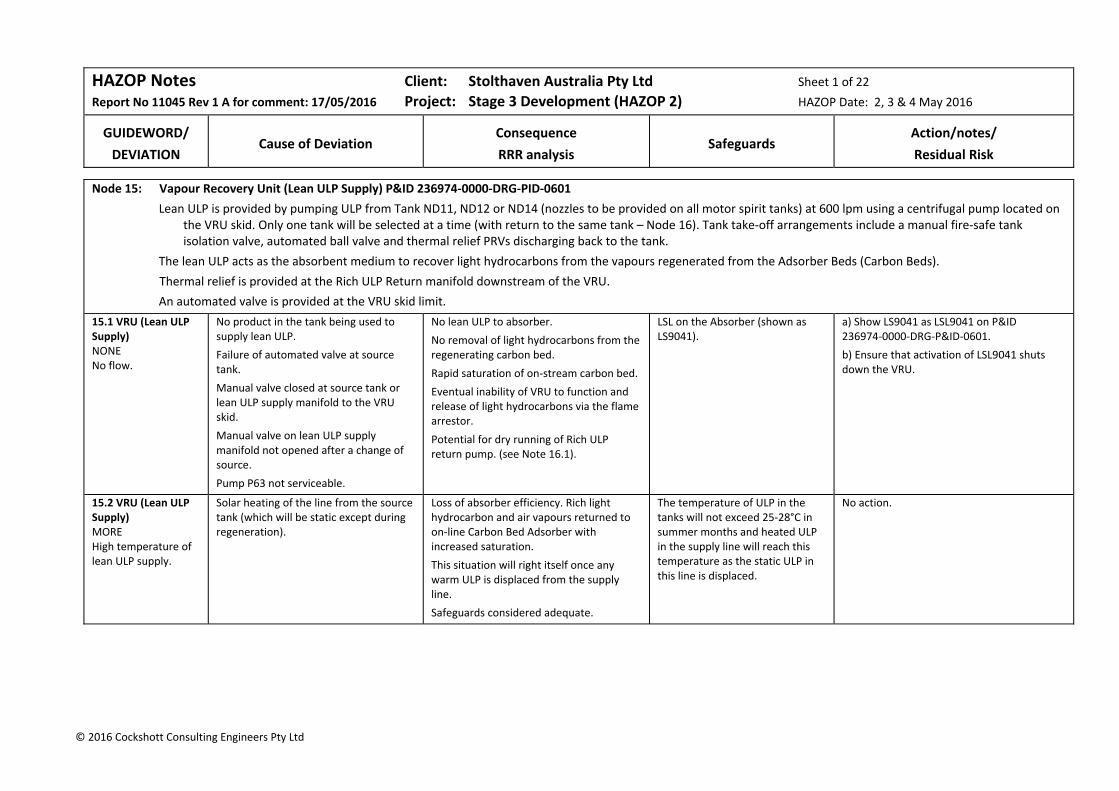
HAZOP Notes Client: Stolthaven Australia Pty Ltd Sheet 1 of 22
Report No 11045 Rev 1 A for comment: 17/05/2016 Project: Stage 3 Development (HAZOP 2) HAZOP Date: 2, 3 & 4 May 2016
GUIDEWORD/
DEVIATION
Cause of Deviation
Consequence
RRR analysis
Safeguards
Action/notes/
Residual Risk
© 2016 Cockshott Consulting Engineers Pty Ltd
Node 15: Vapour Recovery Unit (Lean ULP Supply) P&ID 236974‐0000‐DRG‐PID‐0601
Lean ULP is provided by pumping ULP from Tank ND11, ND12 or ND14 (nozzles to be provided on all motor spirit tanks) at 600 lpm using a centrifugal pump located on the VRU skid. Only one tank will be selected at a time (with return to the same tank – Node 16). Tank take‐off arrangements include a manual fire‐safe tank isolation valve, automated ball valve and thermal relief PRVs discharging back to the tank.
The lean ULP acts as the absorbent medium to recover light hydrocarbons from the vapours regenerated from the Adsorber Beds (Carbon Beds).
Thermal relief is provided at the Rich ULP Return manifold downstream of the VRU.
An automated valve is provided at the VRU skid limit.
15.1 VRU (Lean ULP Supply) NONE No flow.
No product in the tank being used to supply lean ULP.
Failure of automated valve at source tank.
Manual valve closed at source tank or lean ULP supply manifold to the VRU skid.
Manual valve on lean ULP supply manifold not opened after a change of source.
Pump P63 not serviceable.
No lean ULP to absorber.
No removal of light hydrocarbons from the regenerating carbon bed.
Rapid saturation of on‐stream carbon bed.
Eventual inability of VRU to function and release of light hydrocarbons via the flame arrestor.
Potential for dry running of Rich ULP return pump. (see Note 16.1).
LSL on the Absorber (shown as LS9041).
a) Show LS9041 as LSL9041 on P&ID 236974‐0000‐DRG‐P&ID‐0601.
b) Ensure that activation of LSL9041 shuts down the VRU.
15.2 VRU (Lean ULP Supply) MORE High temperature of lean ULP supply.
Solar heating of the line from the source tank (which will be static except during regeneration).
Loss of absorber efficiency. Rich light hydrocarbon and air vapours returned to on‐line Carbon Bed Adsorber with increased saturation.
This situation will right itself once any warm ULP is displaced from the supply line.
Safeguards considered adequate.
The temperature of ULP in the tanks will not exceed 25‐28°C in summer months and heated ULP in the supply line will reach this temperature as the static ULP in this line is displaced.
No action.
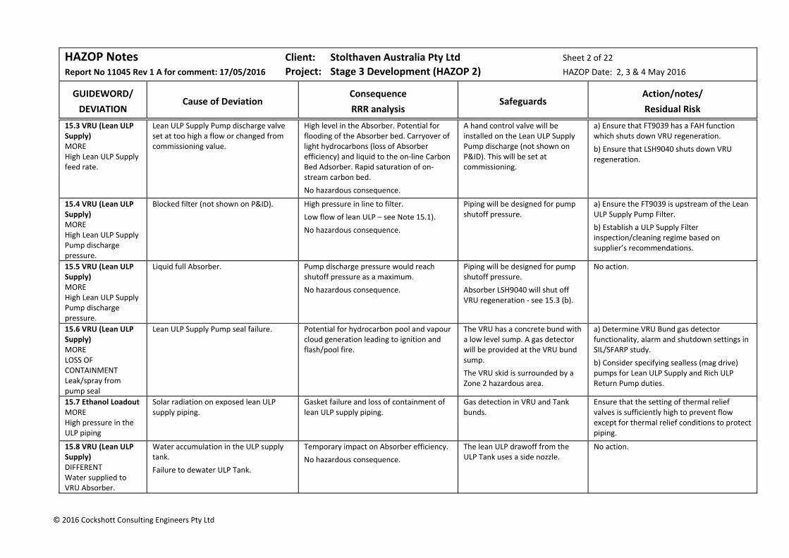
HAZOP Notes Client: Stolthaven Australia Pty Ltd Sheet 2 of 22
Report No 11045 Rev 1 A for comment: 17/05/2016 Project: Stage 3 Development (HAZOP 2) HAZOP Date: 2, 3 & 4 May 2016
GUIDEWORD/
DEVIATION
Cause of Deviation
Consequence
RRR analysis
Safeguards
Action/notes/
Residual Risk
© 2016 Cockshott Consulting Engineers Pty Ltd
15.3 VRU (Lean ULP Supply) MORE High Lean ULP Supply feed rate.
Lean ULP Supply Pump discharge valve set at too high a flow or changed from commissioning value.
High level in the Absorber. Potential for flooding of the Absorber bed. Carryover of light hydrocarbons (loss of Absorber efficiency) and liquid to the on‐line Carbon Bed Adsorber. Rapid saturation of on‐stream carbon bed.
No hazardous consequence.
A hand control valve will be installed on the Lean ULP Supply Pump discharge (not shown on P&ID). This will be set at commissioning.
a) Ensure that FT9039 has a FAH function which shuts down VRU regeneration.
b) Ensure that LSH9040 shuts down VRU regeneration.
15.4 VRU (Lean ULP Supply) MORE High Lean ULP Supply Pump discharge pressure.
Blocked filter (not shown on P&ID).
High pressure in line to filter.
Low flow of lean ULP – see Note 15.1).
No hazardous consequence.
Piping will be designed for pump shutoff pressure.
a) Ensure the FT9039 is upstream of the Lean ULP Supply Pump Filter.
b) Establish a ULP Supply Filter inspection/cleaning regime based on supplier’s recommendations.
15.5 VRU (Lean ULP Supply) MORE High Lean ULP Supply Pump discharge pressure.
Liquid full Absorber. Pump discharge pressure would reach shutoff pressure as a maximum.
No hazardous consequence.
Piping will be designed for pump shutoff pressure.
Absorber LSH9040 will shut off VRU regeneration ‐ see 15.3 (b).
No action.
15.6 VRU (Lean ULP Supply) MORE LOSS OF CONTAINMENT Leak/spray from pump seal
Lean ULP Supply Pump seal failure. Potential for hydrocarbon pool and vapour cloud generation leading to ignition and flash/pool fire.
The VRU has a concrete bund with a low level sump. A gas detector will be provided at the VRU bund sump.
The VRU skid is surrounded by a Zone 2 hazardous area.
a) Determine VRU Bund gas detector functionality, alarm and shutdown settings in SIL/SFARP study.
b) Consider specifying sealless (mag drive) pumps for Lean ULP Supply and Rich ULP Return Pump duties.
15.7 Ethanol Loadout MORE High pressure in the ULP piping
Solar radiation on exposed lean ULP supply piping.
Gasket failure and loss of containment of lean ULP supply piping.
Gas detection in VRU and Tank bunds.
Ensure that the setting of thermal relief valves is sufficiently high to prevent flow except for thermal relief conditions to protect piping.
15.8 VRU (Lean ULP Supply) DIFFERENT Water supplied to VRU Absorber.
Water accumulation in the ULP supply tank.
Failure to dewater ULP Tank.
Temporary impact on Absorber efficiency.
No hazardous consequence.
The lean ULP drawoff from the ULP Tank uses a side nozzle.
No action.
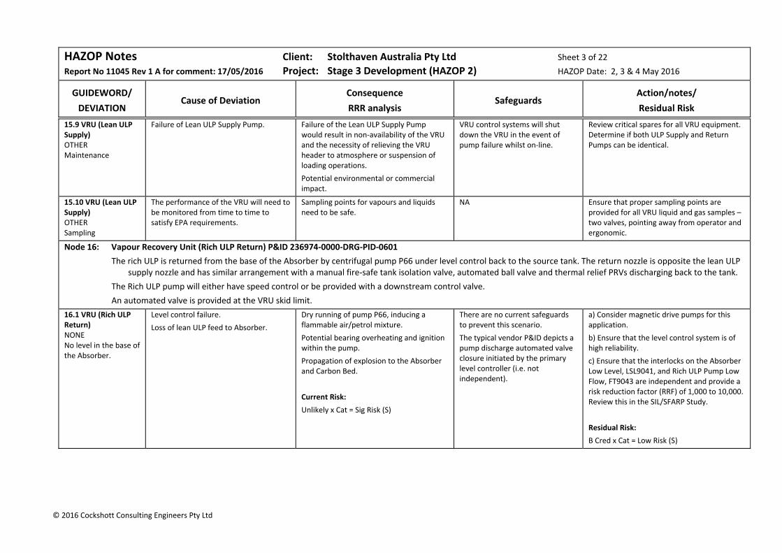
HAZOP Notes Client: Stolthaven Australia Pty Ltd Sheet 3 of 22
Report No 11045 Rev 1 A for comment: 17/05/2016 Project: Stage 3 Development (HAZOP 2) HAZOP Date: 2, 3 & 4 May 2016
GUIDEWORD/
DEVIATION
Cause of Deviation
Consequence
RRR analysis
Safeguards
Action/notes/
Residual Risk
© 2016 Cockshott Consulting Engineers Pty Ltd
15.9 VRU (Lean ULP Supply) OTHER Maintenance
Failure of Lean ULP Supply Pump. Failure of the Lean ULP Supply Pump would result in non‐availability of the VRU and the necessity of relieving the VRU header to atmosphere or suspension of loading operations.
Potential environmental or commercial impact.
VRU control systems will shut down the VRU in the event of pump failure whilst on‐line.
Review critical spares for all VRU equipment. Determine if both ULP Supply and Return Pumps can be identical.
15.10 VRU (Lean ULP Supply) OTHER Sampling
The performance of the VRU will need to be monitored from time to time to satisfy EPA requirements.
Sampling points for vapours and liquids need to be safe.
NA Ensure that proper sampling points are provided for all VRU liquid and gas samples – two valves, pointing away from operator and ergonomic.
Node 16: Vapour Recovery Unit (Rich ULP Return) P&ID 236974‐0000‐DRG‐PID‐0601
The rich ULP is returned from the base of the Absorber by centrifugal pump P66 under level control back to the source tank. The return nozzle is opposite the lean ULP supply nozzle and has similar arrangement with a manual fire‐safe tank isolation valve, automated ball valve and thermal relief PRVs discharging back to the tank.
The Rich ULP pump will either have speed control or be provided with a downstream control valve.
An automated valve is provided at the VRU skid limit.
16.1 VRU (Rich ULP Return) NONE No level in the base of the Absorber.
Level control failure.
Loss of lean ULP feed to Absorber.
Dry running of pump P66, inducing a flammable air/petrol mixture.
Potential bearing overheating and ignition within the pump.
Propagation of explosion to the Absorber and Carbon Bed.
Current Risk:
Unlikely x Cat = Sig Risk (S)
There are no current safeguards to prevent this scenario.
The typical vendor P&ID depicts a pump discharge automated valve closure initiated by the primary level controller (i.e. not independent).
a) Consider magnetic drive pumps for this application.
b) Ensure that the level control system is of high reliability.
c) Ensure that the interlocks on the Absorber Low Level, LSL9041, and Rich ULP Pump Low Flow, FT9043 are independent and provide a risk reduction factor (RRF) of 1,000 to 10,000. Review this in the SIL/SFARP Study.
Residual Risk:
B Cred x Cat = Low Risk (S)

HAZOP Notes Client: Stolthaven Australia Pty Ltd Sheet 4 of 22
Report No 11045 Rev 1 A for comment: 17/05/2016 Project: Stage 3 Development (HAZOP 2) HAZOP Date: 2, 3 & 4 May 2016
GUIDEWORD/
DEVIATION
Cause of Deviation
Consequence
RRR analysis
Safeguards
Action/notes/
Residual Risk
© 2016 Cockshott Consulting Engineers Pty Ltd
16.2 VRU (Rich ULP Return) No flow of rich ULP return.
Pump P66 failure.
Control failure (pump P66 stopped or downstream control valve closed).
Increase in Absorber liquid level. Carryover of liquid to the Carbon Bed with early breakthrough and VRU shutdown.
Absorber high level switch LSH9040.
Carbon bead exhaust vapour analytical instrument breakthrough detection.
a) Ensure that Carbon Bed breakthrough detection shuts down the VRU.
b) Ensure that LSL0141 is independent of the level control system.
16.3 VRU (Rich ULP Return) MORE High pressure in the Absorber
Pump P66 failure or rich ULP return circuit valves closed.
Liquid full Absorber.
Pump P63 discharge pressure would reach shutoff pressure as a maximum.
No hazardous consequence.
Piping will be designed for pump shutoff pressure.
Absorber LSH9040 will shut off VRU regeneration ‐ see 15.3 (b).
No action.
16.4 VRU (Rich ULP Return) MORE High pressure in ULP return piping.
Solar radiation on exposed rich ULP return piping.
Gasket failure and loss of containment of rich ULP return piping.
Gas detection in VRU and Tank bunds.
Ensure that the setting of thermal relief valves is sufficiently high to avoid flow except for thermal relief conditions to protect piping.
16.5 VRU (Rich ULP Return) DIFFERENT Different volatilities of ULP.
The vapour pressure of motor spirit will vary depending on the season. This will impact on the vapours from the gantry and the performance of the lean ULP to recover regenerated hydrocarbons.
Both VRU demand and VRU efficiency will be impacted by the seasonal volatility of motor spirits.
No hazardous consequence.
NA Calculate the impact on the VRU recovery of variations in the volatility of ULP and PULP.
Node 17: Vapour Recovery Unit (Vapours from Lots 2 & 36) P&ID 236974‐0000‐DRG‐PID‐0601
Vapours rich in light hydrocarbons are fed to the on‐stream Carbon Bed Adsorber through a liquid knock‐out pot.
Lean vapours exit from the top of the carbon bed to the atmosphere. Exhaust is continuously monitored for EPA compliance and flammability. The on‐stream bed is switched to regeneration when it has become sufficiently saturated.
17.1 VRU (Vapours) NONE No flow of rich petrol vapour from the gantry.
No trucks filling (no consequence).
Valve closed in the vapour line to the Carbon Bed.
Gantry header pressure will increase and divert to atmosphere when the PRV9034 set pressure is reached.
PRV9034 vents to a safe location. Provide a pressure transmitter in the VRU inlet header to alarm in the event of excessive pressure (lower than PRV9034 set pressure).

HAZOP Notes Client: Stolthaven Australia Pty Ltd Sheet 5 of 22
Report No 11045 Rev 1 A for comment: 17/05/2016 Project: Stage 3 Development (HAZOP 2) HAZOP Date: 2, 3 & 4 May 2016
GUIDEWORD/
DEVIATION
Cause of Deviation
Consequence
RRR analysis
Safeguards
Action/notes/
Residual Risk
© 2016 Cockshott Consulting Engineers Pty Ltd
17.2 VRU (Vapours) MORE Higher flow of vapour to VRU than the design capacity.
The design is based on 10 bays operating at 80%.
In addition, for tank purging, vapours may be directed to the VRU.
Inability to treat all vapour from the gantry; increase in header pressure; diversion of hydrocarbon vapour to the atmosphere.
Exceedance of EPA limits.
The VRU will need to be specified with a reasonable margin to cope with all foreseeable conditions.
a) review with potential supplier the capacity of the VRU and its ability to handle tank purging vapours.
b) Determine the quantity of tank purging vapours for a single tank using venturi induction and estimate tank purging time. Confirm that these vapours can be handled by the VRU.
17.3 VRU (Vapours) MORE High Adsorber bed temperature.
Hot spots in the Carbon Bed. Potential for fire and destruction of the VRU.
Disruption of operations pending unit repair.
Potential ignition of flammable vapour on switching to regeneration, with an internal explosion.
Current Risk:
Rare x Cat = Sig Risk (S)
No thermal processes (steam or hot gases) are used for regenerating the carbon bed.
There are no chemicals which are likely to give rise to hot spots.
Bed and outlet temperature alarms.
No hot spots in VRUs recovering gasoline vapour resulting in fire had been reported in over 85 million hours (as reported in the 2001 Edition and no hot spot had been reported between then and the second edition in 2008 (“Vapour Recovery Units – Guidance on preventing and controlling temperature excursions in carbon beds”, energy institute Second Edition 2008.)
a) Review the design of the VRU to determine the need for alarms and interlocks and the need for any auxiliary systems such as sprays.
b) Determine if the use of nitrogen is feasible as a desorption medium for regeneration.
c) Determine the residual risk during the SIL/SFARP Study.
17.4 VRU (Vapours) OTHER Sampling
Stolthaven will be required to prove the performance of the VRU from time to time, as agreed with the EPA.
On‐line analysis and ease of sampling of both liquids and vapours will enable ongoing performance monitoring and rectification before performance becomes an EPA issue. The details of on‐line analysis have not yet been determined.
NA Specify that adequate vapour analytical instrumentation is to be provided to determine unit efficiency and performance and confirm EPA conditions.
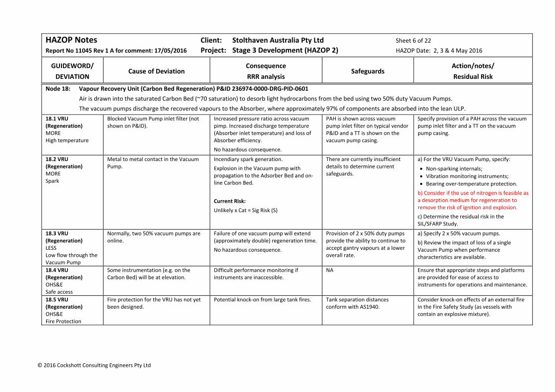
HAZOP Notes Client: Stolthaven Australia Pty Ltd Sheet 6 of 22
Report No 11045 Rev 1 A for comment: 17/05/2016 Project: Stage 3 Development (HAZOP 2) HAZOP Date: 2, 3 & 4 May 2016
GUIDEWORD/
DEVIATION
Cause of Deviation
Consequence
RRR analysis
Safeguards
Action/notes/
Residual Risk
© 2016 Cockshott Consulting Engineers Pty Ltd
Node 18: Vapour Recovery Unit (Carbon Bed Regeneration) P&ID 236974‐0000‐DRG‐PID‐0601
Air is drawn into the saturated Carbon Bed (~70 saturation) to desorb light hydrocarbons from the bed using two 50% duty Vacuum Pumps.
The vacuum pumps discharge the recovered vapours to the Absorber, where approximately 97% of components are absorbed into the lean ULP.
18.1 VRU (Regeneration) MORE High temperature
Blocked Vacuum Pump inlet filter (not shown on P&ID).
Increased pressure ratio across vacuum pimp. Increased discharge temperature (Absorber inlet temperature) and loss of Absorber efficiency.
No hazardous consequence.
PAH is shown across vacuum pump inlet filter on typical vendor P&ID and a TT is shown on the vacuum pump casing.
Specify provision of a PAH across the vacuum pump inlet filter and a TT on the vacuum pump casing.
18.2 VRU (Regeneration) MORE Spark
Metal to metal contact in the Vacuum Pump.
Incendiary spark generation.
Explosion in the Vacuum pump with propagation to the Adsorber Bed and on‐line Carbon Bed.
Current Risk:
Unlikely x Cat = Sig Risk (S)
There are currently insufficient details to determine current safeguards.
a) For the VRU Vacuum Pump, specify:
Non‐sparking internals; Vibration monitoring instruments;
Bearing over‐temperature protection.
b) Consider if the use of nitrogen is feasible as a desorption medium for regeneration to remove the risk of ignition and explosion.
c) Determine the residual risk in the SIL/SFARP Study.
18.3 VRU (Regeneration) LESS Low flow through the Vacuum Pump
Normally, two 50% vacuum pumps are online.
Failure of one vacuum pump will extend (approximately double) regeneration time.
No hazardous consequence.
Provision of 2 x 50% duty pumps provide the ability to continue to accept gantry vapours at a lower overall rate.
a) Specify 2 x 50% vacuum pumps.
b) Review the impact of loss of a single Vacuum Pump when performance characteristics are available.
18.4 VRU (Regeneration) OHS&E Safe access
Some instrumentation (e.g. on the Carbon Bed) will be at elevation.
Difficult performance monitoring if instruments are inaccessible.
NA Ensure that appropriate steps and platforms are provided for ease of access to instruments for operations and maintenance.
18.5 VRU (Regeneration) OHS&E Fire Protection
Fire protection for the VRU has not yet been designed.
Potential knock‐on from large tank fires. Tank separation distances conform with AS1940.
Consider knock‐on effects of an external fire in the Fire Safety Study (as vessels with contain an explosive mixture).
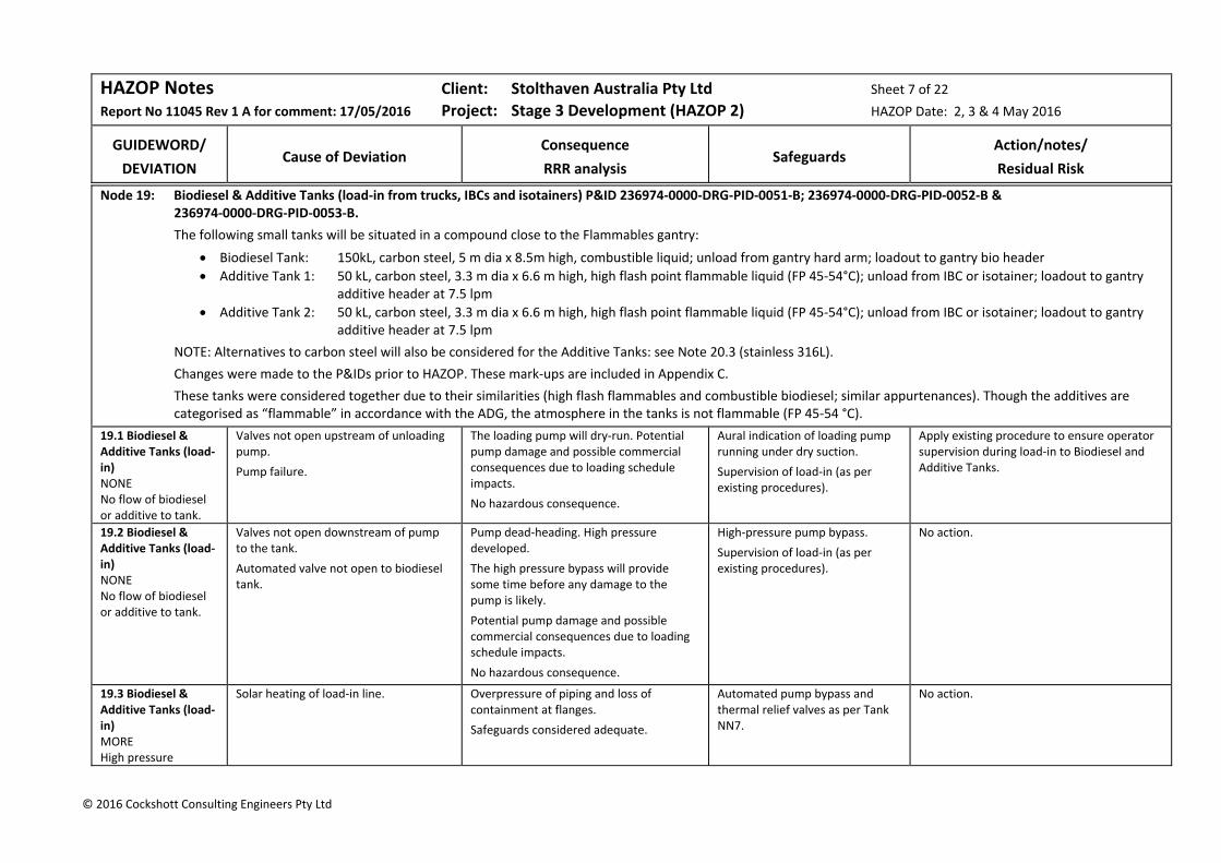
HAZOP Notes Client: Stolthaven Australia Pty Ltd Sheet 7 of 22
Report No 11045 Rev 1 A for comment: 17/05/2016 Project: Stage 3 Development (HAZOP 2) HAZOP Date: 2, 3 & 4 May 2016
GUIDEWORD/
DEVIATION
Cause of Deviation
Consequence
RRR analysis
Safeguards
Action/notes/
Residual Risk
© 2016 Cockshott Consulting Engineers Pty Ltd
Node 19: Biodiesel & Additive Tanks (load‐in from trucks, IBCs and isotainers) P&ID 236974‐0000‐DRG‐PID‐0051‐B; 236974‐0000‐DRG‐PID‐0052‐B & 236974‐0000‐DRG‐PID‐0053‐B.
The following small tanks will be situated in a compound close to the Flammables gantry:
Biodiesel Tank: 150kL, carbon steel, 5 m dia x 8.5m high, combustible liquid; unload from gantry hard arm; loadout to gantry bio header
Additive Tank 1: 50 kL, carbon steel, 3.3 m dia x 6.6 m high, high flash point flammable liquid (FP 45‐54°C); unload from IBC or isotainer; loadout to gantry additive header at 7.5 lpm
Additive Tank 2: 50 kL, carbon steel, 3.3 m dia x 6.6 m high, high flash point flammable liquid (FP 45‐54°C); unload from IBC or isotainer; loadout to gantry additive header at 7.5 lpm
NOTE: Alternatives to carbon steel will also be considered for the Additive Tanks: see Note 20.3 (stainless 316L).
Changes were made to the P&IDs prior to HAZOP. These mark‐ups are included in Appendix C.
These tanks were considered together due to their similarities (high flash flammables and combustible biodiesel; similar appurtenances). Though the additives are categorised as “flammable” in accordance with the ADG, the atmosphere in the tanks is not flammable (FP 45‐54 °C).
19.1 Biodiesel & Additive Tanks (load‐in) NONE No flow of biodiesel or additive to tank.
Valves not open upstream of unloading pump.
Pump failure.
The loading pump will dry‐run. Potential pump damage and possible commercial consequences due to loading schedule impacts.
No hazardous consequence.
Aural indication of loading pump running under dry suction.
Supervision of load‐in (as per existing procedures).
Apply existing procedure to ensure operator supervision during load‐in to Biodiesel and Additive Tanks.
19.2 Biodiesel & Additive Tanks (load‐in) NONE No flow of biodiesel or additive to tank.
Valves not open downstream of pump to the tank.
Automated valve not open to biodiesel tank.
Pump dead‐heading. High pressure developed.
The high pressure bypass will provide some time before any damage to the pump is likely.
Potential pump damage and possible commercial consequences due to loading schedule impacts.
No hazardous consequence.
High‐pressure pump bypass.
Supervision of load‐in (as per existing procedures).
No action.
19.3 Biodiesel & Additive Tanks (load‐in) MORE High pressure
Solar heating of load‐in line. Overpressure of piping and loss of containment at flanges.
Safeguards considered adequate.
Automated pump bypass and thermal relief valves as per Tank NN7.
No action.
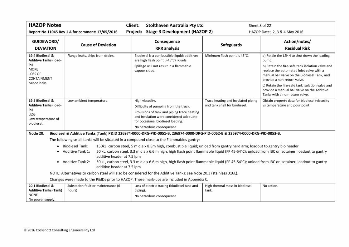
HAZOP Notes Client: Stolthaven Australia Pty Ltd Sheet 8 of 22
Report No 11045 Rev 1 A for comment: 17/05/2016 Project: Stage 3 Development (HAZOP 2) HAZOP Date: 2, 3 & 4 May 2016
GUIDEWORD/
DEVIATION
Cause of Deviation
Consequence
RRR analysis
Safeguards
Action/notes/
Residual Risk
© 2016 Cockshott Consulting Engineers Pty Ltd
19.4 Biodiesel & Additive Tanks (load‐in) MORE LOSS OF CONTAINMENT Minor leaks.
Flange leaks, drips from drains. Biodiesel is a combustible liquid; additives are high flash point (>45°C) liquids.
Spillage will not result in a flammable vapour cloud.
Minimum flash point is 45°C. a) Retain the LSHH to shut down the loading pump.
b) Retain the fire‐safe tank isolation valve and replace the automated inlet valve with a manual ball valve on the Biodiesel Tank, and provide a non‐return valve.
c) Retain the fire‐safe tank isolation valve and provide a manual ball valve on the Additive Tanks with a non‐return valve.
19.5 Biodiesel & Additive Tanks (load‐in) LESS Low temperature of biodiesel.
Low ambient temperature. High viscosity.
Difficulty of pumping from the truck.
Provisions of tank and piping trace heating and insulation were considered adequate for occasional biodiesel loading.
No hazardous consequence.
Trace heating and insulated piping and tank shell for biodiesel.
Obtain property data for biodiesel (viscosity vs temperature and pour point).
Node 20: Biodiesel & Additive Tanks (Tank) P&ID 236974‐0000‐DRG‐PID‐0051‐B; 236974‐0000‐DRG‐PID‐0052‐B & 236974‐0000‐DRG‐PID‐0053‐B.
The following small tanks will be situated in a compound close to the Flammables gantry:
Biodiesel Tank: 150kL, carbon steel, 5 m dia x 8.5m high, combustible liquid; unload from gantry hard arm; loadout to gantry bio header
Additive Tank 1: 50 kL, carbon steel, 3.3 m dia x 6.6 m high, high flash point flammable liquid (FP 45‐54°C); unload from IBC or isotainer; loadout to gantry additive header at 7.5 lpm
Additive Tank 2: 50 kL, carbon steel, 3.3 m dia x 6.6 m high, high flash point flammable liquid (FP 45‐54°C); unload from IBC or isotainer; loadout to gantry additive header at 7.5 lpm
NOTE: Alternatives to carbon steel will also be considered for the Additive Tanks: see Note 20.3 (stainless 316L).
Changes were made to the P&IDs prior to HAZOP. These mark‐ups are included in Appendix C.
20.1 Biodiesel & Additive Tanks (Tank) NONE No power supply.
Substation fault or maintenance (6 hours)
Loss of electric tracing (biodiesel tank and piping).
No hazardous consequence.
High thermal mass in biodiesel tank.
No action.
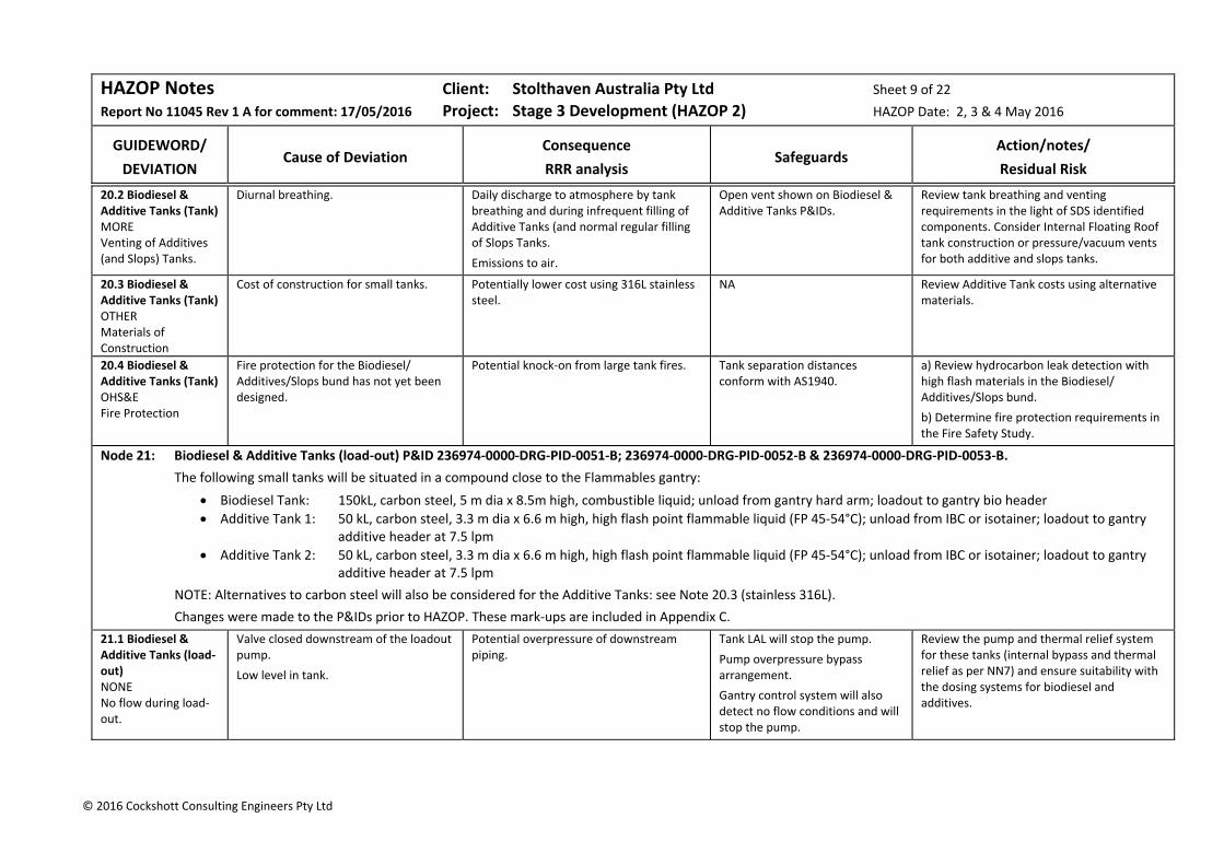
HAZOP Notes Client: Stolthaven Australia Pty Ltd Sheet 9 of 22
Report No 11045 Rev 1 A for comment: 17/05/2016 Project: Stage 3 Development (HAZOP 2) HAZOP Date: 2, 3 & 4 May 2016
GUIDEWORD/
DEVIATION
Cause of Deviation
Consequence
RRR analysis
Safeguards
Action/notes/
Residual Risk
© 2016 Cockshott Consulting Engineers Pty Ltd
20.2 Biodiesel & Additive Tanks (Tank) MORE Venting of Additives (and Slops) Tanks.
Diurnal breathing. Daily discharge to atmosphere by tank breathing and during infrequent filling of Additive Tanks (and normal regular filling of Slops Tanks.
Emissions to air.
Open vent shown on Biodiesel & Additive Tanks P&IDs.
Review tank breathing and venting requirements in the light of SDS identified components. Consider Internal Floating Roof tank construction or pressure/vacuum vents for both additive and slops tanks.
20.3 Biodiesel & Additive Tanks (Tank) OTHER Materials of Construction
Cost of construction for small tanks. Potentially lower cost using 316L stainless steel.
NA Review Additive Tank costs using alternative materials.
20.4 Biodiesel & Additive Tanks (Tank) OHS&E Fire Protection
Fire protection for the Biodiesel/ Additives/Slops bund has not yet been designed.
Potential knock‐on from large tank fires. Tank separation distances conform with AS1940.
a) Review hydrocarbon leak detection with high flash materials in the Biodiesel/ Additives/Slops bund.
b) Determine fire protection requirements in the Fire Safety Study.
Node 21: Biodiesel & Additive Tanks (load‐out) P&ID 236974‐0000‐DRG‐PID‐0051‐B; 236974‐0000‐DRG‐PID‐0052‐B & 236974‐0000‐DRG‐PID‐0053‐B.
The following small tanks will be situated in a compound close to the Flammables gantry:
Biodiesel Tank: 150kL, carbon steel, 5 m dia x 8.5m high, combustible liquid; unload from gantry hard arm; loadout to gantry bio header
Additive Tank 1: 50 kL, carbon steel, 3.3 m dia x 6.6 m high, high flash point flammable liquid (FP 45‐54°C); unload from IBC or isotainer; loadout to gantry additive header at 7.5 lpm
Additive Tank 2: 50 kL, carbon steel, 3.3 m dia x 6.6 m high, high flash point flammable liquid (FP 45‐54°C); unload from IBC or isotainer; loadout to gantry additive header at 7.5 lpm
NOTE: Alternatives to carbon steel will also be considered for the Additive Tanks: see Note 20.3 (stainless 316L).
Changes were made to the P&IDs prior to HAZOP. These mark‐ups are included in Appendix C.
21.1 Biodiesel & Additive Tanks (load‐out) NONE No flow during load‐out.
Valve closed downstream of the loadout pump.
Low level in tank.
Potential overpressure of downstream piping.
Tank LAL will stop the pump.
Pump overpressure bypass arrangement.
Gantry control system will also detect no flow conditions and will stop the pump.
Review the pump and thermal relief system for these tanks (internal bypass and thermal relief as per NN7) and ensure suitability with the dosing systems for biodiesel and additives.
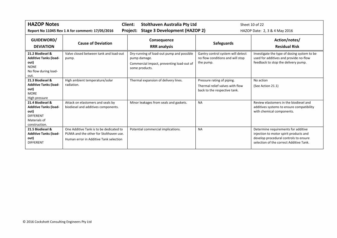
HAZOP Notes Client: Stolthaven Australia Pty Ltd Sheet 10 of 22
Report No 11045 Rev 1 A for comment: 17/05/2016 Project: Stage 3 Development (HAZOP 2) HAZOP Date: 2, 3 & 4 May 2016
GUIDEWORD/
DEVIATION
Cause of Deviation
Consequence
RRR analysis
Safeguards
Action/notes/
Residual Risk
© 2016 Cockshott Consulting Engineers Pty Ltd
21.2 Biodiesel & Additive Tanks (load‐out) NONE No flow during load‐out.
Valve closed between tank and load‐out pump.
Dry‐running of load‐out pump and possible pump damage.
Commercial impact, preventing load‐out of some products.
Gantry control system will detect no flow conditions and will stop the pump.
Investigate the type of dosing system to be used for additives and provide no‐flow feedback to stop the delivery pump.
21.3 Biodiesel & Additive Tanks (load‐out) MORE High pressure
High ambient temperature/solar radiation.
Thermal expansion of delivery lines. Pressure rating of piping.
Thermal relief valves with flow back to the respective tank.
No action
(See Action 21.1)
21.4 Biodiesel & Additive Tanks (load‐out) DIFFERENT Materials of construction.
Attack on elastomers and seals by biodiesel and additives components.
Minor leakages from seals and gaskets. NA Review elastomers in the biodiesel and additives systems to ensure compatibility with chemical components.
21.5 Biodiesel & Additive Tanks (load‐out) DIFFERENT
One Additive Tank is to be dedicated to PUMA and the other for Stolthaven use.
Human error in Additive Tank selection
Potential commercial implications. NA Determine requirements for additive injection to motor spirit products and develop procedural controls to ensure selection of the correct Additive Tank.
HAZOP Notes Client: Stolthaven Australia Pty Ltd Sheet 11 of 22
Report No 11045 Rev 1 A for comment: 17/05/2016 Project: Stage 3 Development (HAZOP 2) HAZOP Date: 2, 3 & 4 May 2016
GUIDEWORD/
DEVIATION
Cause of Deviation
Consequence
RRR analysis
Safeguards
Action/notes/
Residual Risk
© 2016 Cockshott Consulting Engineers Pty Ltd
Node 22: Drainage System Option 1 (Gravity Drainage) P&ID 236974‐0000‐DRG‐PID‐0502‐D
Option 1 involves closed gravity drainage (through three systems):
from the flammables and combustibles tank compound sumps;
from an intermediate pit collecting driveway first flush and from the remote impounding basin:
from the additive bund sump, VRU bund sump, pump raft bund sumps and switchroom paving.
Runoff from fire access roads is directed to the outlet pit without treatment.
Three Puraceptors treat the potentially contaminated water, removing free hydrocarbons in the water. Should the level of hydrocarbons in any Puraceptor fill the hydrocarbon chamber, an internal ball valve will prevent water passage to the coalescer chamber and prevent discharge to the outlet pit.
Normal bund management procedures will be employed. Specifically accumulated water is inspected to ensure that there is no evidence of hydrocarbons, before opening the relevant bund valve, which is located within the bund.
22.1 Drainage System Option 1 (Gravity) NONE No flow to Puraceptor
Puraceptor internal valve shuts (due to accumulation of hydrocarbons).
Potentially contaminated water will back up in the drainage system and levels in all bunds being discharged will reach a common level (in each system). There is potential for overflow (e.g. at pump raft or VRU bunds) and potential loss of containment.
Potential soil contamination and EPA action.
Check the potential back‐up levels for a large rainfall event and determine how bund overflow and loss of containment can be prevented by procedural controls.
22.2 Drainage System Option 1 (Gravity) NONE Failure of conductivity probe in Puraceptor.
Instrument failure. Build‐up will normally take a long time before the Puraceptor chamber will need to be emptied of hydrocarbon.
Loss of early warning of hydrocarbon build‐up.
Automatic closure of Puraceptor internal valve when the first chamber fills with hydrocarbon.
Determine if the conductivity transmitter provides a fault signal and determine a maintenance schedule for this instrument.
22.3 Drainage System Option 1 (Gravity) MORE Hydrocarbons in potentially contaminated bund water.
Spillage or leaks in the any bund, including additives bund, pump raft bunds or VRU bund.
Human error during bund water inspection.
Build‐up of hydrocarbons in the first Puraceptor chamber. Eventual closure of valve and discharge to outlet pit prevented. (For further consequences see Note 22.1)
Conductivity detection change (XE/AT in the first Puraceptor chamber).
Automatic closure of Puraceptor internal valve when the first chamber fills with hydrocarbon.
Review bund management procedures to ensure that provision is made to handle contaminated water in the bunds.
HAZOP Notes Client: Stolthaven Australia Pty Ltd Sheet 12 of 22
Report No 11045 Rev 1 A for comment: 17/05/2016 Project: Stage 3 Development (HAZOP 2) HAZOP Date: 2, 3 & 4 May 2016
GUIDEWORD/
DEVIATION
Cause of Deviation
Consequence
RRR analysis
Safeguards
Action/notes/
Residual Risk
© 2016 Cockshott Consulting Engineers Pty Ltd
22.4 Drainage System Option 1 (Gravity) MORE High pressure
Head of water in bunds being drained. This is not an issue for a gravity system. The Puraceptor inlet pressure will depend on the head of water in the bunds being drained.
No hazardous consequence.
Restriction orifice provided in the common drain line.
No action.
22.5 Drainage System Option 1 (Gravity) DIFFERENT Emulsion fed to Puraceptor.
Emulsification when gravity draining contaminated water.
Emulsification will not occur with gravity drainage.
NA No action.
22.6 Drainage System Option 1 (Gravity) DIFFERENT Fire water foam sent to the Puraceptor.
Firewater foam in the tank bunds as a result of testing or activation in the event of an emergency.
It is likely that foam will pass through the Puraceptor resulting in contamination to water.
NA Ensure that the bund management procedure covers disposal of fire water/foam in the event of activation of the foam system.
22.7 Drainage System Option 1 (Gravity) DIFFERENT Ethanol in potentially contaminated water
Spillage from the ethanol Tank and piping system or ethanol pump seal.
Ethanol will pass through the Puraceptor and be diluted with drained water.
Ethanol is biodegradable. No action.
22.8 Drainage System Option 1 (Gravity) OTHER Maintenance.
Inadequate maintenance. If inadequate maintenance is performed the Puraceptor will eventually fill with hydrocarbon and the internal valve will close and discharge to the outlet pit will be prevented. (For further consequences see Note 22.1)
NA Establish an appropriate maintenance regime and procedure for removal and disposal of accumulated hydrocarbons.
22.9 Drainage System Option 1 (Gravity) OTHER Reduce complexity
Reduce the number of Puraceptors. The number of Puraceptors is determined by site falls. These is no opportunity to reduce the number of Puraceptors for this option.
NA No action.
HAZOP Notes Client: Stolthaven Australia Pty Ltd Sheet 13 of 22
Report No 11045 Rev 1 A for comment: 17/05/2016 Project: Stage 3 Development (HAZOP 2) HAZOP Date: 2, 3 & 4 May 2016
GUIDEWORD/
DEVIATION
Cause of Deviation
Consequence
RRR analysis
Safeguards
Action/notes/
Residual Risk
© 2016 Cockshott Consulting Engineers Pty Ltd
22.10 Drainage System Option 1 (Gravity) OTHER ESD Action.
Bund valves are operated manually and several may be open at once.
In the event of a hydrocarbon loss of containment, hydrocarbon would be trapped in the Puraceptor until the chamber is filled with hydrocarbon and the internal valve closes.
If multiple bund valves are open for drainage, levels will reach a common level by hydrostatic balance.
Potential flow of contaminated bund water to another compound, extending the potential hazard.
Current Risk:
Rare x Maj = Mod Risk (S)
Tank valves close on ESD activation.
It is not intended to provide an automated SOV to or from the Puraceptor. In any case, this would not resolve this problem.
No action.
Residual Risk:
Rare x Maj = Mod Risk (S)
22.11 Drainage System Option 1 (Gravity) OHS&E
Due to site falls, a high rainfall event can result in water depths of up to 0.5m at the bund low point sump in the existing bunds.
Access to the bund sump valve through water is hazardous.
Current Risk:
Likely x Minor = Sig Risk (S)
Ensure that the bund valves are operable from the bund walls and provide stirs/platforms for access to valve handles and for taking samples.
Residual Risk:
Risk eliminated
HAZOP Notes Client: Stolthaven Australia Pty Ltd Sheet 14 of 22
Report No 11045 Rev 1 A for comment: 17/05/2016 Project: Stage 3 Development (HAZOP 2) HAZOP Date: 2, 3 & 4 May 2016
GUIDEWORD/
DEVIATION
Cause of Deviation
Consequence
RRR analysis
Safeguards
Action/notes/
Residual Risk
© 2016 Cockshott Consulting Engineers Pty Ltd
Node 23: Drainage System Option 2 (Pumpout) P&ID 236974‐0000‐DRG‐PID‐0502‐D
Option 2 involves pumpout (through three closed systems):
from the flammables and combustibles tank compound sumps;
from the driveway first flush pit and from the remote impounding basin:
from the additive bund sump, VRU bund sump, pump raft bund sumps and switchroom paving.
Runoff from fire access roads is directed to the outlet pit without treatment.
Three Puraceptors treat the potentially contaminated water, removing free hydrocarbons in the water. Should the level of hydrocarbons in any Puraceptor fill the hydrocarbon chamber, an internal ball valve will prevent water passage to the coalescer chamber and prevent discharge to the outlet pit.
Normal bund management procedures will be employed. Specifically accumulated water is inspected to ensure that there is no evidence of hydrocarbons, before pumping out the relevant bund. The bund pump will be located on the bund wall.
23.1 Drainage System Option 2 (Pumpout) No flow to Puraceptor
Puraceptor internal valve shuts (due to accumulation of hydrocarbons).
Levels inside bund will not be affected as reverse flow is prevented by a non‐return valve and by the pumpout pump stalling.
No hazardous consequence.
No action.
23.2 Drainage System Option 2 (Pumpout) NONE Failure of conductivity probe in Puraceptor.
Instrument failure. Build‐up will normally take a long time before the Puraceptor chamber will need to be emptied of hydrocarbon.
Loss of early warning of hydrocarbon build‐up.
Automatic closure of Puraceptor internal valve when the first chamber fills with hydrocarbon.
Determine if the conductivity transmitter provides a fault signal and determine a maintenance schedule for this instrument.
23.3 Drainage System Option 2 (Pumpout) MORE Hydrocarbons in potentially contaminated bund water.
Spillage or leaks in the any bund, including additives bund, pump raft bunds or VRU bund.
Human error during bund water inspection.
Build‐up of hydrocarbons in the first Puraceptor chamber. Eventual closure of valve and discharge to outlet pit prevented. (For further consequences see Note 23.1)
Conductivity detection change (XE/AT in the first Puraceptor chamber).
Automatic closure of Puraceptor internal valve when the first chamber fills with hydrocarbon.
Review bund management procedures to ensure that provision is made to handle contaminated water in the bunds.

HAZOP Notes Client: Stolthaven Australia Pty Ltd Sheet 15 of 22
Report No 11045 Rev 1 A for comment: 17/05/2016 Project: Stage 3 Development (HAZOP 2) HAZOP Date: 2, 3 & 4 May 2016
GUIDEWORD/
DEVIATION
Cause of Deviation
Consequence
RRR analysis
Safeguards
Action/notes/
Residual Risk
© 2016 Cockshott Consulting Engineers Pty Ltd
23.4 Drainage System Option 2 (Pumpout) MORE High pressure to the Puraceptor
Too many pumpout pumps operating simultaneously.
Potential overpressure of drainage system and capacity of Puraceptor exceeded.
Bund pumps will be push button to start or stop and automatic stop by sump level (float).
a) Ensure that the pumpout pumps’ design outlet pressures are sufficiently low so as not to overpressurise the closed drainage system and the capacities such that the system will not be overloaded.
b) Determine if an orifice plate provides any useful function for the pumpout option.
c) Determine if the Puraceptor vent stack (overflow) can be directed to the nearest bund.
23.5 Drainage System Option 2 (Pumpout) DIFFERENT Emulsion fed to Puraceptor.
Emulsification by the bund pumpout pump of contaminated water.
In the case of an oil sheen, it is unlikely that emulsification will occur.
Potential for discharge to the outlet pit exceeding EPA specification.
Bund management procedures – contaminated water is not sent to the Puraceptor.
Ensure that bund pumpout pumps are not high shear.
23.6 Drainage System Option 2 (Pumpout) DIFFERENT Fire water foam sent to the Puraceptor.
Firewater foam in the tank bunds as a result of testing or activation in the event of an emergency.
It is likely that foam will pass through the Puraceptor resulting in contamination to water.
NA Ensure that the bund management procedure covers disposal of fire water/foam in the event of activation of the foam system.
23.7 Drainage System Option 2 (Pumpout) DIFFERENT Ethanol in potentially contaminated water
Spillage from the ethanol Tank and piping system or ethanol pump seal.
Ethanol will pass through the Puraceptor and be diluted with drained water.
Ethanol is biodegradable. No action.
23.8 Drainage System Option 2 (Pumpout) OTHER Maintenance.
Inadequate maintenance. If inadequate maintenance is performed the Puraceptor will eventually fill with hydrocarbon and the internal valve will close and discharge to the outlet pit will be prevented. (For further consequences see Note 23.1)
NA Establish an appropriate maintenance regime and procedure for removal and disposal of accumulated hydrocarbons.
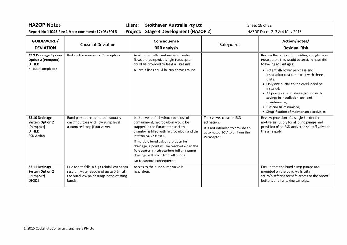
HAZOP Notes Client: Stolthaven Australia Pty Ltd Sheet 16 of 22
Report No 11045 Rev 1 A for comment: 17/05/2016 Project: Stage 3 Development (HAZOP 2) HAZOP Date: 2, 3 & 4 May 2016
GUIDEWORD/
DEVIATION
Cause of Deviation
Consequence
RRR analysis
Safeguards
Action/notes/
Residual Risk
© 2016 Cockshott Consulting Engineers Pty Ltd
23.9 Drainage System Option 2 (Pumpout) OTHER Reduce complexity
Reduce the number of Puraceptors. As all potentially contaminated water flows are pumped, a single Puraceptor could be provided to treat all streams.
All drain lines could be run above ground.
Review the option of providing a single large Puraceptor. This would potentially have the following advantages:
Potentially lower purchase and installation cost compared with three units;
Only one outfall to the creek need be installed;
All piping can run above ground with savings in installation cost and maintenance;
Cut and fill minimised;
Simplification of maintenance activities.
23.10 Drainage System Option 2 (Pumpout) OTHER ESD Action
Bund pumps are operated manually on/off buttons with low sump level automated stop (float valve).
In the event of a hydrocarbon loss of containment, hydrocarbon would be trapped in the Puraceptor until the chamber is filled with hydrocarbon and the internal valve closes.
If multiple bund valves are open for drainage, a point will be reached when the Puraceptor is hydrocarbon‐full and pump drainage will cease from all bunds
No hazardous consequence.
Tank valves close on ESD activation.
It is not intended to provide an automated SOV to or from the Puraceptor.
Review provision of a single header for motive air supply for all bund pumps and provision of an ESD‐activated shutoff valve on the air supply.
23.11 Drainage System Option 2 (Pumpout) OHS&E
Due to site falls, a high rainfall event can result in water depths of up to 0.5m at the bund low point sump in the existing bunds.
Access to the bund sump valve is hazardous.
Ensure that the bund sump pumps are mounted on the bund walls with stairs/platforms for safe access to the on/off buttons and for taking samples.

HAZOP Notes Client: Stolthaven Australia Pty Ltd Sheet 17 of 22
Report No 11045 Rev 1 A for comment: 17/05/2016 Project: Stage 3 Development (HAZOP 2) HAZOP Date: 2, 3 & 4 May 2016
GUIDEWORD/
DEVIATION
Cause of Deviation
Consequence
RRR analysis
Safeguards
Action/notes/
Residual Risk
© 2016 Cockshott Consulting Engineers Pty Ltd
Node 24: Slops System (Slops Receival) P&ID 236974‐0000‐DRG‐PID‐0501‐E
Node 24 covers the transfer into the slops tank.
Two slops tanks will be situated in a compound close to the flammables gantry:
Slops Tank ND30 50 kL, stainless steel 316L, 3.3 m dia x 6.6 m high, high flash point flammable liquid (FP 45‐54°C); slops from gantry and tank compounds; loadout to slops truck at 300 ‐ 600 lpm
Slops Tank ND31: 50 kL, stainless steel 316L, 3.3 m dia x 6.6 m high, high flash point flammable liquid (FP 45‐54°C); slops from gantry and tank compounds; loadout to slops truck at 300 – 600 lpm
The slops tanks receive slops (primarily water with potentially some hydrocarbons) from tank drainage. Tank drainage was HAZOPed previously.
The slops tanks also receive slops from drain‐dry pumps and the gantry tundish.
As both tanks are identical, tank ND30 has been taken as an exemplar. All actions apply to both tanks.
24.1 Slops System (Slops Receival) NONE Reverse flow from pressurised slops header.
Slops header is pressurised. Reverse flow was considered non‐credible. Non‐return valves are provided at each slops pump and after the slops tank manifold valves. Slops pumps are diaphragm type which itself acts as a non‐return valve.
Note that before the HAZOP, it was agreed to provide each manifold valve with a non‐return valve.
No action.
24.2 Slops System (Slops Receival) MORE Ignition of slops tank vapours.
Lightning striking tank. The vapour space in the slops tank is likely to be flammable (hydrocarbon layer floating on water).
Potential ignition of tank flammable vapours. Explosion close to loading gantry.
Naked Risk:
E Rare x Cat = Mod Risk (S)
Current Risk:
N Cred x Cat = Low Risk (S)
A flame arrester is provided on the tank PSV (or PVV) to protect the tank vapours from outside sources of ignition.
No action
Residual Risk:
N Cred x Cat = Low Risk (S)

HAZOP Notes Client: Stolthaven Australia Pty Ltd Sheet 18 of 22
Report No 11045 Rev 1 A for comment: 17/05/2016 Project: Stage 3 Development (HAZOP 2) HAZOP Date: 2, 3 & 4 May 2016
GUIDEWORD/
DEVIATION
Cause of Deviation
Consequence
RRR analysis
Safeguards
Action/notes/
Residual Risk
© 2016 Cockshott Consulting Engineers Pty Ltd
24.3 Slops System (Slops Receival) MORE Future sources of slops.
Provision is made to add future connections to the Slops Tank inlet header.
Two spare connections are shown on the P&ID – one valved and one shown with a blind flange. The latter was considered adequate.
NA Terminate spare connections with a blind flange.
24.4 Slops System (Slops Receival) MORE External (bund) fire in biodiesel/additives/ slops bund
The slops tank inlet valve will always be open (unlike product, additives and biodiesel tanks).
Note that the outlet valve will normally be closed.
An external fire could result in inlet piping failure and the release of slops from the Slops Tank into the bund, adding fuel to the fire.
Provision of foam application to the Biodiesel/Additives/Slops bund.
Provide a fire‐safe check valve before the fire‐safe Slops Tank inlet valve.
24.5 Slops System (Slops Receival) MORE High level in slops tank.
The terminal may be unmanned. Slops will continually be added from the gantries.
Potentially to overfill the slops vessel with flammable liquid (the top phase) spraying from the PRV (or PVV).
With an unmanned facility, it was considered that an overfill event could occur once per year. This might lead to a flammable vapour cloud an ignition (ignition assumes as a 1/10 chance.
Current Risk:
Likelihood: 1/yr x 0.1 = 1/10 year (Moderate)
Mod x Cat = High Risk (S)
The Slops Tank is in an area classified as hazardous with ignition sources excluded ‐chance of ignition probability is assumed as 0.1.
a) Provide a LAH interlocked to an automated Slops Tank inlet valve.
b) Provide a separate LSHH interlocked to the site ESD.
c) Provide an air supply system for the dewatering, bund drainage and gantry slops pumps (See Action 23.10 for bund pumps) which will be isolated in the event of a site ESD.
d) Ensure that Slops Tank LAH‐inlet valve SIF and LSHH‐motive air SIF are included in the SIL/SFARP Study.
Residual Risk:
Assuming both LAH‐inlet valve SIF is SIL2 and LSHH‐motive air SIF is SIL2, then the likelihood is:
1/10/yr x /100 x 1/100 = 100,000 /yr
B Cred x Cat = Low Risk (S)
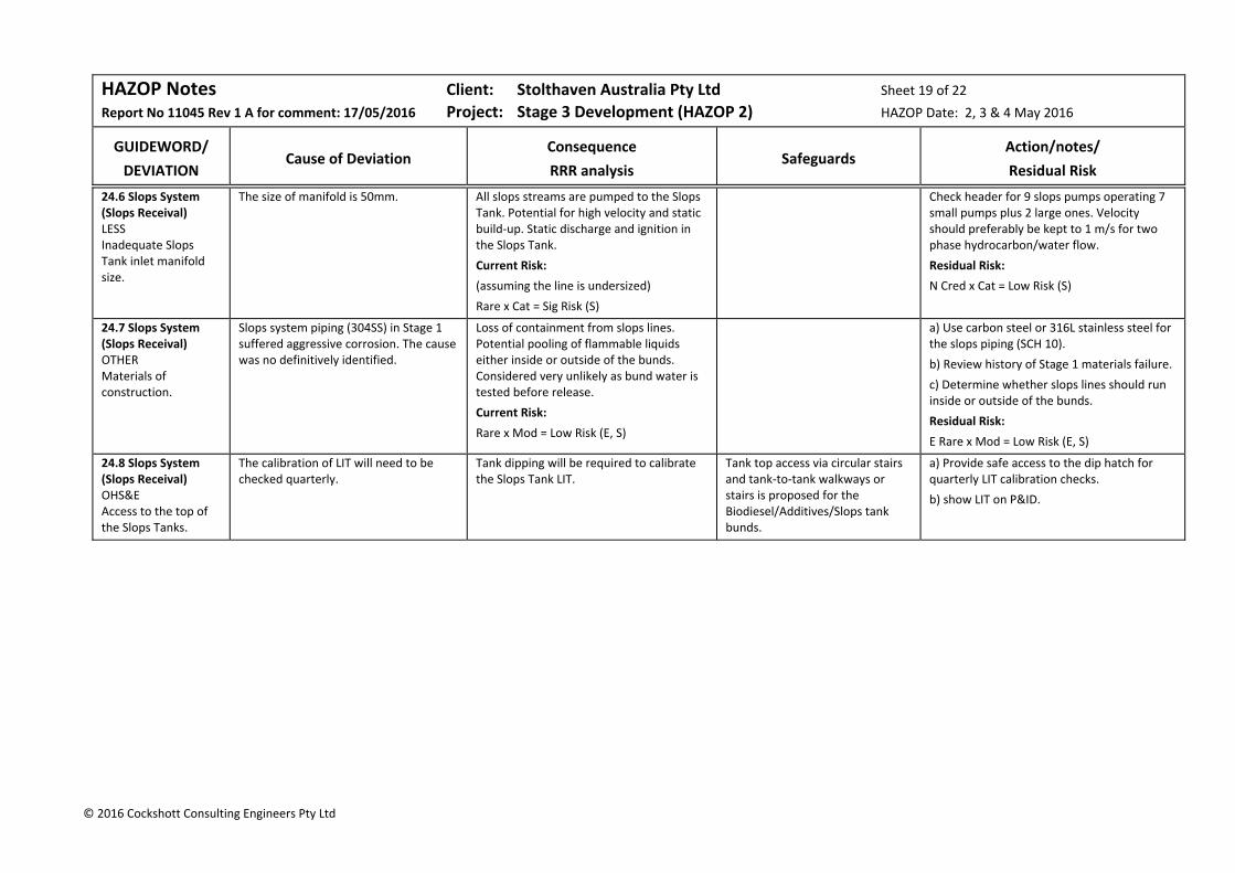
HAZOP Notes Client: Stolthaven Australia Pty Ltd Sheet 19 of 22
Report No 11045 Rev 1 A for comment: 17/05/2016 Project: Stage 3 Development (HAZOP 2) HAZOP Date: 2, 3 & 4 May 2016
GUIDEWORD/
DEVIATION
Cause of Deviation
Consequence
RRR analysis
Safeguards
Action/notes/
Residual Risk
© 2016 Cockshott Consulting Engineers Pty Ltd
24.6 Slops System (Slops Receival) LESS Inadequate Slops Tank inlet manifold size.
The size of manifold is 50mm. All slops streams are pumped to the Slops Tank. Potential for high velocity and static build‐up. Static discharge and ignition in the Slops Tank.
Current Risk:
(assuming the line is undersized)
Rare x Cat = Sig Risk (S)
Check header for 9 slops pumps operating 7 small pumps plus 2 large ones. Velocity should preferably be kept to 1 m/s for two phase hydrocarbon/water flow.
Residual Risk:
N Cred x Cat = Low Risk (S)
24.7 Slops System (Slops Receival) OTHER Materials of construction.
Slops system piping (304SS) in Stage 1 suffered aggressive corrosion. The cause was no definitively identified.
Loss of containment from slops lines. Potential pooling of flammable liquids either inside or outside of the bunds. Considered very unlikely as bund water is tested before release.
Current Risk:
Rare x Mod = Low Risk (E, S)
a) Use carbon steel or 316L stainless steel for the slops piping (SCH 10).
b) Review history of Stage 1 materials failure.
c) Determine whether slops lines should run inside or outside of the bunds.
Residual Risk:
E Rare x Mod = Low Risk (E, S)
24.8 Slops System (Slops Receival) OHS&E Access to the top of the Slops Tanks.
The calibration of LIT will need to be checked quarterly.
Tank dipping will be required to calibrate the Slops Tank LIT.
Tank top access via circular stairs and tank‐to‐tank walkways or stairs is proposed for the Biodiesel/Additives/Slops tank bunds.
a) Provide safe access to the dip hatch for quarterly LIT calibration checks.
b) show LIT on P&ID.
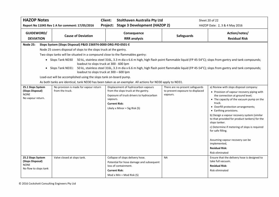
HAZOP Notes Client: Stolthaven Australia Pty Ltd Sheet 20 of 22
Report No 11045 Rev 1 A for comment: 17/05/2016 Project: Stage 3 Development (HAZOP 2) HAZOP Date: 2, 3 & 4 May 2016
GUIDEWORD/
DEVIATION
Cause of Deviation
Consequence
RRR analysis
Safeguards
Action/notes/
Residual Risk
© 2016 Cockshott Consulting Engineers Pty Ltd
Node 25: Slops System (Slops Disposal) P&ID 236974‐0000‐DRG‐PID‐0501‐E
Node 25 covers disposal of slops to the slops truck at the gantry.
Two slops tanks will be situated in a compound close to the flammables gantry:
Slops Tank ND30 50 kL, stainless steel 316L, 3.3 m dia x 6.6 m high, high flash point flammable liquid (FP 45‐54°C); slops from gantry and tank compounds; loadout to slops truck at 300 ‐ 600 lpm
Slops Tank ND31: 50 kL, stainless steel 316L, 3.3 m dia x 6.6 m high, high flash point flammable liquid (FP 45‐54°C); slops from gantry and tank compounds; loadout to slops truck at 300 – 600 lpm
Load‐out will be accomplished using the slops tank on‐board pump.
As both tanks are identical, tank ND30 has been taken as an exemplar. All actions for ND30 apply to ND31.
25.1 Slops System (Slops Disposal) NONE No vapour return.
No provision is made for vapour return from the truck.
Displacement of hydrocarbon vapours from the slops truck at the gantry.
Exposure of truck drivers to hydrocarbon vapours.
Current Risk:
Likely x Minor = Sig Risk (S)
There are no present safeguards to prevent exposure to displaced vapours.
a) Review with slops disposal company:
Provision of vapour recovery piping with the connection at ground level;
The capacity of the vacuum pump on the truck.
Overfill protection arrangements;
Earthing provisions. b) Design a vapour recovery system (similar to that provided for product tankers) for the slops tanker.
c) Determine if metering of slops is required for safe filling.
Assuming vapour recovery can be implemented,
Residual Risk:
Risk eliminated
25.2 Slops System (Slops Disposal) NONE No flow to slops tank
Valve closed at slops tank. Collapse of slops delivery hose.
Potential for hose damage and subsequent loss of containment.
Current Risk:
Mod x Min = Mod Risk (S)
NA Ensure that the delivery hose is designed to take full vacuum.
Residual Risk:
Risk eliminated

HAZOP Notes Client: Stolthaven Australia Pty Ltd Sheet 21 of 22
Report No 11045 Rev 1 A for comment: 17/05/2016 Project: Stage 3 Development (HAZOP 2) HAZOP Date: 2, 3 & 4 May 2016
GUIDEWORD/
DEVIATION
Cause of Deviation
Consequence
RRR analysis
Safeguards
Action/notes/
Residual Risk
© 2016 Cockshott Consulting Engineers Pty Ltd
25.3 Slops System (Slops Disposal) NONE No flow to slops tank.
Slops truck on‐board pump unserviceable.
Delay to slops disposal.
No hazardous consequence.
NA Provide a 50mm stub and blanked valve at a low point on the delivery line as a low point drain and for connection of a temporary transfer pump.
25.4 Slops System (Slops Disposal) MORE LOSS OF CONTAINMENT
Open drain connection or transfer hose not connected.
Gravity draining to the gantry drain when slops tank valve opened.
This will drain to the remote impounding basin and could activate the gas alarm and initiate automatic foam application to the RIB.
Current Risk:
Mod x Min = Mod Risk (S)
NA a) Develop a procedure for slops disposal. Ensure that the operation is supervised by an operator.
b) Provide a ball valve at the fire‐safe slops tank isolation valve.
Residual Risk:
Unlikely x Min = Low Risk (S)
25.5 Slops System (Slops Disposal) MORE High velocity in transfer line to slops tanker.
Pump capacity too high. Velocity in transfer line results in static electricity generation (two‐phase hydrocarbon/water flow).
Final details not currently known. a) Review slops tanker on‐board pump capacity and ensure that the line velocity does not result in the potential for static generation (two phase hydrocarbon/water flow).
b) Ensure provision is made for tanker earthing and electrical continuity. Ensure that earthing is included in the procedure.
c) If tank dipping is required, specify a minimum relaxation time in the procedure.
25.6 Slops System (Slops Disposal) LESS Low flow to slops tanker.
Slow slops tanker loading rate. Excessive time to load slops tanker.
Inability to use Bay 1 for product loading.
No hazardous consequence.
Final details not currently known. Aim for slops loading rate of 300 lpm (18 kL per hour). As a balance between loading time and static generation.
25.7 Slops System (Slops Disposal) LESS Low level in slops tank.
Slops tank emptied during slops transfer.
Potential to draw air into slops tanker on‐board tank. The two‐phase air/hydrocarbon mixture may also give rise to static electricity.
NA Determine the minimum level that should remain in the slops tank after disposal and include how this should be controlled in the procedure. (Is the LAL required as a safeguard in addition to monitoring level?)
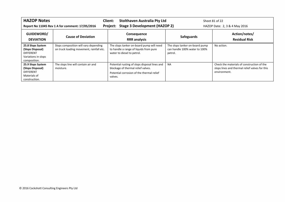
HAZOP Notes Client: Stolthaven Australia Pty Ltd Sheet 81 of 22
Report No 11045 Rev 1 A for comment: 17/05/2016 Project: Stage 3 Development (HAZOP 2) HAZOP Date: 2, 3 & 4 May 2016
GUIDEWORD/
DEVIATION
Cause of Deviation
Consequence
RRR analysis
Safeguards
Action/notes/
Residual Risk
© 2016 Cockshott Consulting Engineers Pty Ltd
25.8 Slops System (Slops Disposal) DIFFERENT Variations in slops composition.
Slops composition will vary depending on truck loading movement, rainfall etc.
The slops tanker on‐board pump will need to handle a range of liquids from pure water to diesel to petrol.
The slops tanker on‐board pump can handle 100% water to 100% petrol.
No action.
25.9 Slops System (Slops Disposal) DIFFERENT Materials of construction.
The slops line will contain air and moisture.
Potential rusting of slops disposal lines and blockage of thermal relief valves.
Potential corrosion of the thermal relief valves.
NA Check the materials of construction of the slops lines and thermal relief valves for this environment.

Cockshott Consulting Engineers 80 Report 11045 Rev B: 22 May 2015
7 HAZOP Action List
This Section contains the Action List derived from the HAZOP Notes.
The Action List will be completed progressively.
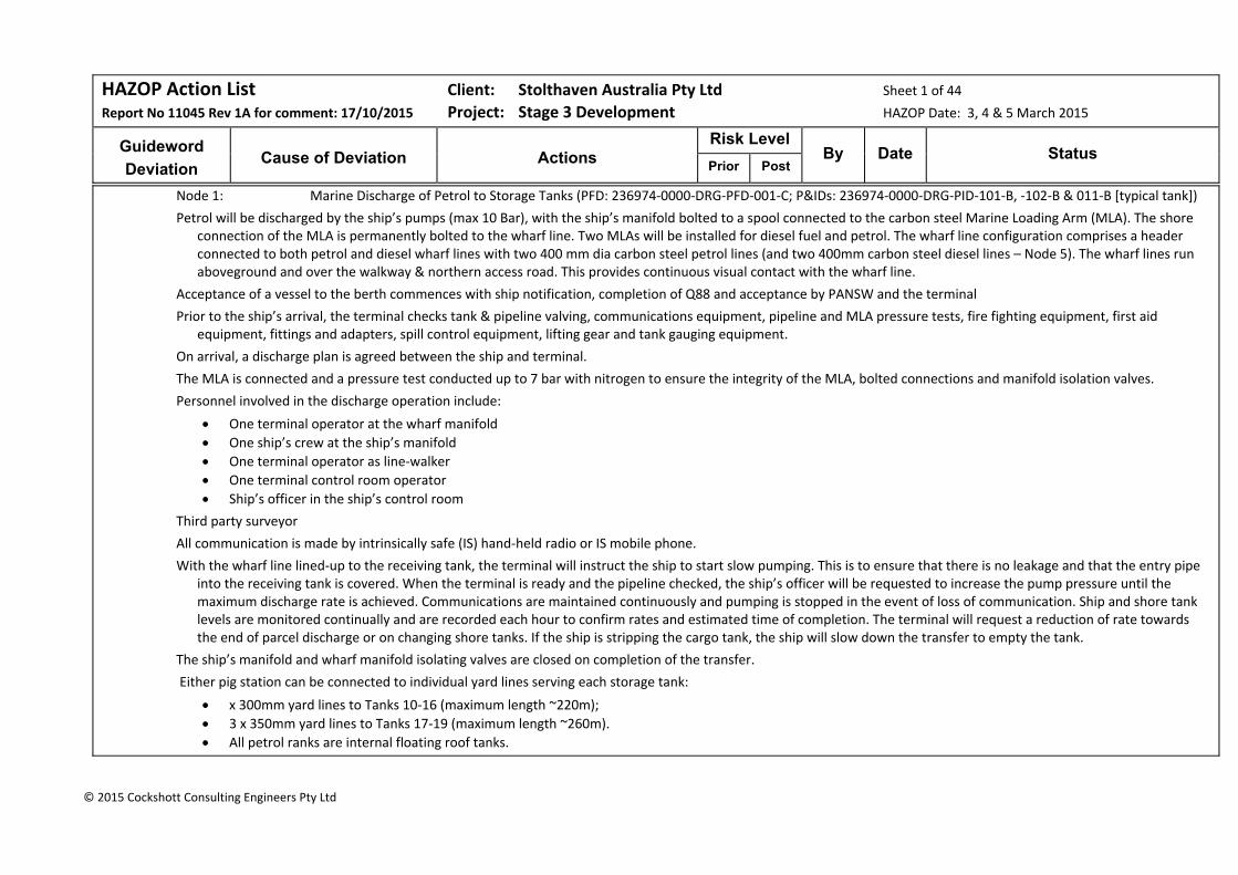
HAZOP Action List Client: Stolthaven Australia Pty Ltd Sheet 1 of 44
Report No 11045 Rev 1A for comment: 17/10/2015 Project: Stage 3 Development HAZOP Date: 3, 4 & 5 March 2015
Guideword
Deviation
Cause of Deviation
Actions
Risk Level By Date Status
Prior Post
© 2015 Cockshott Consulting Engineers Pty Ltd
Node 1: Marine Discharge of Petrol to Storage Tanks (PFD: 236974‐0000‐DRG‐PFD‐001‐C; P&IDs: 236974‐0000‐DRG‐PID‐101‐B, ‐102‐B & 011‐B [typical tank])
Petrol will be discharged by the ship’s pumps (max 10 Bar), with the ship’s manifold bolted to a spool connected to the carbon steel Marine Loading Arm (MLA). The shore connection of the MLA is permanently bolted to the wharf line. Two MLAs will be installed for diesel fuel and petrol. The wharf line configuration comprises a header connected to both petrol and diesel wharf lines with two 400 mm dia carbon steel petrol lines (and two 400mm carbon steel diesel lines – Node 5). The wharf lines run aboveground and over the walkway & northern access road. This provides continuous visual contact with the wharf line.
Acceptance of a vessel to the berth commences with ship notification, completion of Q88 and acceptance by PANSW and the terminal
Prior to the ship’s arrival, the terminal checks tank & pipeline valving, communications equipment, pipeline and MLA pressure tests, fire fighting equipment, first aid equipment, fittings and adapters, spill control equipment, lifting gear and tank gauging equipment.
On arrival, a discharge plan is agreed between the ship and terminal.
The MLA is connected and a pressure test conducted up to 7 bar with nitrogen to ensure the integrity of the MLA, bolted connections and manifold isolation valves.
Personnel involved in the discharge operation include:
One terminal operator at the wharf manifold
One ship’s crew at the ship’s manifold
One terminal operator as line‐walker
One terminal control room operator
Ship’s officer in the ship’s control room
Third party surveyor
All communication is made by intrinsically safe (IS) hand‐held radio or IS mobile phone.
With the wharf line lined‐up to the receiving tank, the terminal will instruct the ship to start slow pumping. This is to ensure that there is no leakage and that the entry pipe into the receiving tank is covered. When the terminal is ready and the pipeline checked, the ship’s officer will be requested to increase the pump pressure until the maximum discharge rate is achieved. Communications are maintained continuously and pumping is stopped in the event of loss of communication. Ship and shore tank levels are monitored continually and are recorded each hour to confirm rates and estimated time of completion. The terminal will request a reduction of rate towards the end of parcel discharge or on changing shore tanks. If the ship is stripping the cargo tank, the ship will slow down the transfer to empty the tank.
The ship’s manifold and wharf manifold isolating valves are closed on completion of the transfer.
Either pig station can be connected to individual yard lines serving each storage tank:
x 300mm yard lines to Tanks 10‐16 (maximum length ~220m);
3 x 350mm yard lines to Tanks 17‐19 (maximum length ~260m).
All petrol ranks are internal floating roof tanks.
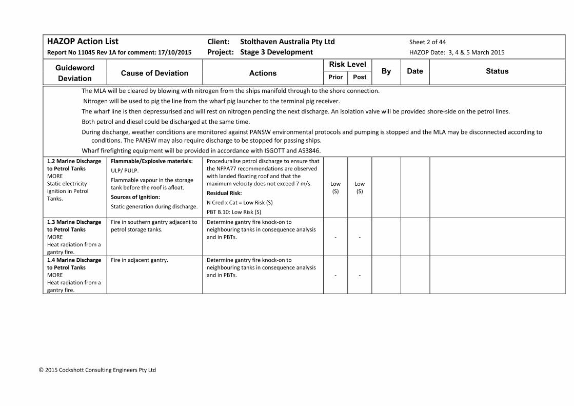
HAZOP Action List Client: Stolthaven Australia Pty Ltd Sheet 2 of 44
Report No 11045 Rev 1A for comment: 17/10/2015 Project: Stage 3 Development HAZOP Date: 3, 4 & 5 March 2015
Guideword
Deviation
Cause of Deviation
Actions
Risk Level By Date Status
Prior Post
© 2015 Cockshott Consulting Engineers Pty Ltd
The MLA will be cleared by blowing with nitrogen from the ships manifold through to the shore connection.
Nitrogen will be used to pig the line from the wharf pig launcher to the terminal pig receiver.
The wharf line is then depressurised and will rest on nitrogen pending the next discharge. An isolation valve will be provided shore‐side on the petrol lines.
Both petrol and diesel could be discharged at the same time.
During discharge, weather conditions are monitored against PANSW environmental protocols and pumping is stopped and the MLA may be disconnected according to conditions. The PANSW may also require discharge to be stopped for passing ships.
Wharf firefighting equipment will be provided in accordance with ISGOTT and AS3846.
1.2 Marine Discharge to Petrol Tanks MORE Static electricity ‐ ignition in Petrol Tanks.
Flammable/Explosive materials:
ULP/ PULP.
Flammable vapour in the storage tank before the roof is afloat.
Sources of Ignition:
Static generation during discharge.
Proceduralise petrol discharge to ensure that the NFPA77 recommendations are observed with landed floating roof and that the maximum velocity does not exceed 7 m/s.
Residual Risk:
N Cred x Cat = Low Risk (S)
PBT B.10: Low Risk (S)
Low (S)
Low (S)
1.3 Marine Discharge to Petrol Tanks MORE Heat radiation from a gantry fire.
Fire in southern gantry adjacent to petrol storage tanks.
Determine gantry fire knock‐on to neighbouring tanks in consequence analysis and in PBTs. ‐ ‐
1.4 Marine Discharge to Petrol Tanks MORE Heat radiation from a gantry fire.
Fire in adjacent gantry. Determine gantry fire knock‐on to neighbouring tanks in consequence analysis and in PBTs. ‐ ‐
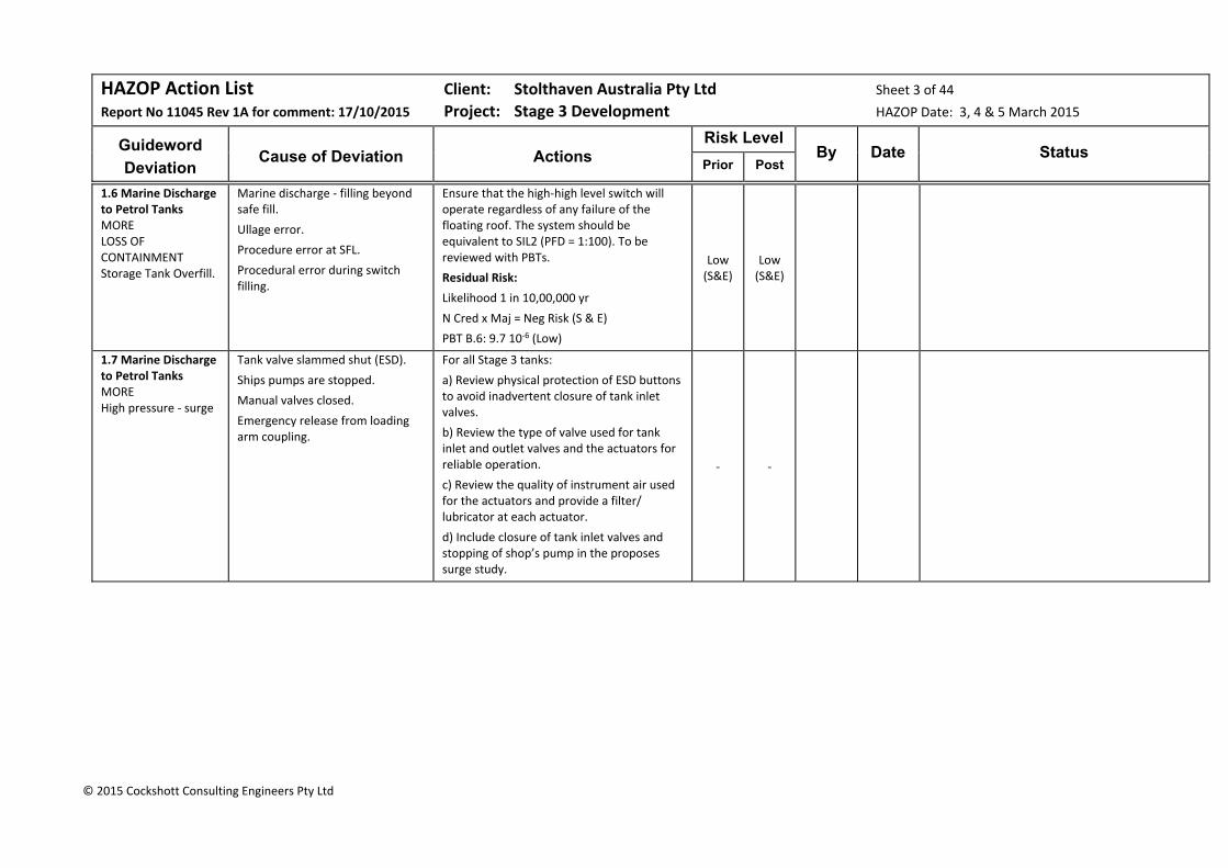
HAZOP Action List Client: Stolthaven Australia Pty Ltd Sheet 3 of 44
Report No 11045 Rev 1A for comment: 17/10/2015 Project: Stage 3 Development HAZOP Date: 3, 4 & 5 March 2015
Guideword
Deviation
Cause of Deviation
Actions
Risk Level By Date Status
Prior Post
© 2015 Cockshott Consulting Engineers Pty Ltd
1.6 Marine Discharge to Petrol Tanks MORE LOSS OF CONTAINMENT Storage Tank Overfill.
Marine discharge ‐ filling beyond safe fill.
Ullage error.
Procedure error at SFL.
Procedural error during switch filling.
Ensure that the high‐high level switch will operate regardless of any failure of the floating roof. The system should be equivalent to SIL2 (PFD = 1:100). To be reviewed with PBTs.
Residual Risk:
Likelihood 1 in 10,00,000 yr
N Cred x Maj = Neg Risk (S & E)
PBT B.6: 9.7 10‐6 (Low)
Low (S&E)
Low (S&E)
1.7 Marine Discharge to Petrol Tanks MORE High pressure ‐ surge
Tank valve slammed shut (ESD).
Ships pumps are stopped.
Manual valves closed.
Emergency release from loading arm coupling.
For all Stage 3 tanks:
a) Review physical protection of ESD buttons to avoid inadvertent closure of tank inlet valves.
b) Review the type of valve used for tank inlet and outlet valves and the actuators for reliable operation.
c) Review the quality of instrument air used for the actuators and provide a filter/ lubricator at each actuator.
d) Include closure of tank inlet valves and stopping of shop’s pump in the proposes surge study.
‐ ‐

HAZOP Action List Client: Stolthaven Australia Pty Ltd Sheet 4 of 44
Report No 11045 Rev 1A for comment: 17/10/2015 Project: Stage 3 Development HAZOP Date: 3, 4 & 5 March 2015
Guideword
Deviation
Cause of Deviation
Actions
Risk Level By Date Status
Prior Post
© 2015 Cockshott Consulting Engineers Pty Ltd
1.8 Marine Discharge to Petrol Tanks MORE Overpressure from ammonium nitrate explosion in port or heat radiation from coal carrier at berth in the channel.
Combustible/Explosive materials:
K2 Berth: bulk ammonium nitrate (2 km).
M4 Berth: packaged ammonium nitrate (1 km).
Coal Bulk Carriers (200m from M7).
Sources of Ignition:
On‐board fire on ammonium nitrate ship at K2;
Contamination of ammonium nitrate with organic materials;
Coal fire in Coal bulk carrier hold.
a) Operations should be halted for any event at the Ammonium Nitrate manufacturing facility (e.g. fire or ammonia release) or cargo fire on a bulk coal carrier.
Residual Risk:
E Rare x Min = Neg Risk (S) Neg (S)
Neg (S)
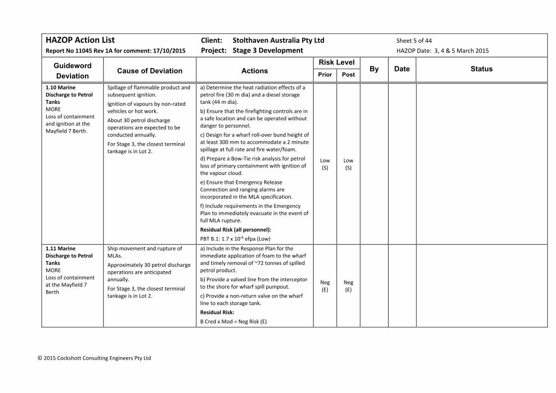
HAZOP Action List Client: Stolthaven Australia Pty Ltd Sheet 5 of 44
Report No 11045 Rev 1A for comment: 17/10/2015 Project: Stage 3 Development HAZOP Date: 3, 4 & 5 March 2015
Guideword
Deviation
Cause of Deviation
Actions
Risk Level By Date Status
Prior Post
© 2015 Cockshott Consulting Engineers Pty Ltd
1.10 Marine Discharge to Petrol Tanks MORE Loss of containment and ignition at the Mayfield 7 Berth.
Spillage of flammable product and subsequent ignition.
Ignition of vapours by non‐rated vehicles or hot work.
About 30 petrol discharge operations are expected to be conducted annually.
For Stage 3, the closest terminal tankage is in Lot 2.
a) Determine the heat radiation effects of a petrol fire (30 m dia) and a diesel storage tank (44 m dia).
b) Ensure that the firefighting controls are in a safe location and can be operated without danger to personnel.
c) Design for a wharf roll‐over bund height of at least 300 mm to accommodate a 2 minute spillage at full rate and fire water/foam.
d) Prepare a Bow‐Tie risk analysis for petrol loss of primary containment with ignition of the vapour cloud.
e) Ensure that Emergency Release Connection and ranging alarms are incorporated in the MLA specification.
f) Include requirements in the Emergency Plan to immediately evacuate in the event of full MLA rupture.
Residual Risk (all personnel):
PBT B.1: 1.7 x 10‐6 efpa (Low)
Low (S)
Low (S)
1.11 Marine Discharge to Petrol Tanks MORE Loss of containment at the Mayfield 7 Berth
Ship movement and rupture of MLAs.
Approximately 30 petrol discharge operations are anticipated annually.
For Stage 3, the closest terminal tankage is in Lot 2.
a) Include in the Response Plan for the immediate application of foam to the wharf and timely removal of ~72 tonnes of spilled petrol product.
b) Provide a valved line from the interceptor to the shore for wharf spill pumpout.
c) Provide a non‐return valve on the wharf line to each storage tank.
Residual Risk:
B Cred x Mod = Neg Risk (E)
Neg (E)
Neg (E)

HAZOP Action List Client: Stolthaven Australia Pty Ltd Sheet 6 of 44
Report No 11045 Rev 1A for comment: 17/10/2015 Project: Stage 3 Development HAZOP Date: 3, 4 & 5 March 2015
Guideword
Deviation
Cause of Deviation
Actions
Risk Level By Date Status
Prior Post
© 2015 Cockshott Consulting Engineers Pty Ltd
1.13 Marine Discharge to Petrol Tanks DIFFERENT Cross‐contamination at wharf and at tank manifold.
Potential cross contamination from wharf manifold to wharf lines (diesel and petrol)
Possible cross contamination from tank manifold to yard lines.
a) For the wharf manifold, review the options of:
Spectacle blind and gate valve;
Double block & cavity valve
Double gate valves and bleed
b) For the tank manifold, replace the double block and cavity valves with gate valves.
‐ ‐
1.15 Marine Discharge to Petrol Tanks OTHER Vehicle impact during Koppers discharge operations.
Koppers will require access for line walks during discharge of their products.
Provide fenced pedestrian access to the Koppers’ pipeline corridor.
‐ ‐
1.16 Marine Discharge to Petrol Tanks OTHER Collapse of internal floating roof.
Failure of fixed roof support columns leading to unbalanced floating, corrosion, failure of various gaskets, etc.
Review with tank fabricators how potential IFR failures can be detected.
‐ ‐
1.17 Marine Discharge to Petrol Tanks OHS&E Ergonomics & exposure. Environmental – loss of containment.
Operation of the pig launcher receivers – opening/closing and manhandling of the pigs.
a) Stolthaven to provide parameters for the pig launchers and receivers (all products)
b) The pig launcher/receiver is to slope away from the door and a drain valve provided at the low point. A drip tray is to be provided at all pig launchers and receivers.
‐ ‐
HAZOP Action List Client: Stolthaven Australia Pty Ltd Sheet 7 of 44
Report No 11045 Rev 1A for comment: 17/10/2015 Project: Stage 3 Development HAZOP Date: 3, 4 & 5 March 2015
Guideword
Deviation
Cause of Deviation
Actions
Risk Level By Date Status
Prior Post
© 2015 Cockshott Consulting Engineers Pty Ltd
1.18 Marine Discharge to Petrol Tanks OHS&E Exposure during IFR roof inspection.
Inspections of floating roofs. a) Ensure that entry of an operator’s head is prevented by an arrangement of bars or mesh at the air scoops.
b) Determine procedures for ensuring that the vapours at the scoops are not hazardous (low oxygen, LEL and VOC metering included as part of the procedure).
‐ ‐
Node 2: Storage of Petrol (ULP & PULP) (P&ID: 236974‐0000‐DRG‐PID‐011‐B)
Each tank has automated inlet and outlet valves which close on site emergency shutdown (ESD) activation. The inlet valve closes automatically on LSHH activation.
Each tank equipped with an internal floating roof (aluminium pontoon, double rim seal) to minimise loss of volatiles to the air environment. Air scoops will provide roof space natural ventilation. The pontoon lower position will either be by the use of legs or chains. PVV protection is provided t o protect the roof from vacuum conditions and to release air or nitrogen from beneath the roof. Foam pourers are provided to direct foam to the roof seals.
The inlet pipe is provided with a diffuser to prevent air forming a large bubble and destabilising the roof. A cone‐down floor and is provided with underfloor tell‐tale leak detection.
A low level drawoff is provided as well as a stripping drawoff from the central sump. The outlet is equipped with an automated isolation valve.
Dewatering is facilitated by a separate drawoff from the central sump to an external tundish and air pump to the Dewatering Tank.
Instrumentation includes PV vents on the internal floating roof, a radar level transmitter with LAH, a LSHH (sensing roof or liquid) and multiple point temperature measurement.
2.1 Storage of Petrol (ULP/PULP) NONE No product in tank.
Initial filling. a) Ensure that tank is initially filled with line velocities below 1 m/s in accordance with NFPA77.
b) Consider floating roof landed state and creation of flammable vapour in PBTs.
‐ ‐
2.2 Storage of Petrol (ULP/PULP) MORE Heat radiation from tank‐on‐fire.
Fire in adjacent flammables tank. Determine risk using PBTs.
‐ ‐
HAZOP Action List Client: Stolthaven Australia Pty Ltd Sheet 8 of 44
Report No 11045 Rev 1A for comment: 17/10/2015 Project: Stage 3 Development HAZOP Date: 3, 4 & 5 March 2015
Guideword
Deviation
Cause of Deviation
Actions
Risk Level By Date Status
Prior Post
© 2015 Cockshott Consulting Engineers Pty Ltd
2.2 Storage of Petrol (ULP/PULP) MORE Heat radiation from VRU.
Loss of containment and fire at VRU.
Ensure that VRU fire is modelled in PBTs and QRA.
‐ ‐
2.3 Storage of Petrol (ULP/PULP) MORE LOSS OF CONTAINMENT Tank breathing.
Discharge of flammable vapours from the vented shell.
Review emissions rates for IFR/cone roof tanks.
‐ ‐
2.8 Storage of Petrol (ULP/PULP) MORE Nitrogen introduction to tank.
Depressurising wharf line to the tank.
a) Investigate how to depressurise wharf lines to shoreside facilities rather than depressurising to the tanks.
b) Review tank inlet hardware to minimise impact of inadvertent introduction of nitrogen.
Expected Residual Risk::
E Rare x Maj = Low Risk (E & C))
PBT B.10: 1.7 x 10‐6 efpa (Low Risk, E& C)
Sig (E&C)
Low (E&C)
2.9 Storage of Petrol (ULP/PULP) LESS Inadequate updating of level readouts.
Currently, it takes ~15 sec for SCADA level updates. With new tanks NN8 & NN9, this could go to 20 sec.
Investigate the cause of slow SCADA level updates and resolve so that these updates are “immediate”. ‐ ‐
2.11 Storage of Petrol (ULP/PULP) OTHER Water on floating roof.
Heavy rainfall event. Ensure that the air scoop design protects against massive ingress of rainwater.
‐ ‐
HAZOP Action List Client: Stolthaven Australia Pty Ltd Sheet 9 of 44
Report No 11045 Rev 1A for comment: 17/10/2015 Project: Stage 3 Development HAZOP Date: 3, 4 & 5 March 2015
Guideword
Deviation
Cause of Deviation
Actions
Risk Level By Date Status
Prior Post
© 2015 Cockshott Consulting Engineers Pty Ltd
2.13 Storage of Petrol (ULP/PULP) OTHER Failure of automated product valves.
Valve actuation failure. a) Establish a test regime for the actuated product inlet and outlet valves.
b) Ensure that a test button is provided to mimic a high‐high level signal and a low level signal.
c) Investigate the use of butterfly valves to minimise actuator loads – consider adequacy of closure and impact on surge calculations.
‐ ‐
Node 3: Petrol Loadout (ULP & PULP) (P&IDs: 236974‐0000‐DRG‐PFD‐011‐B, ‐201‐B, ‐202‐B/302‐B & 401‐B)
Tank ND‐10 is taken as the exemplar for this node.
All ULP/PULP will be loaded to the southern 6‐bay gantry(Bays 1 & 2 dedicated for one client; bays 3 & 4 to a second; bays 5 & 6 to be allocated).
Petrol tanks have a low level drawoff and a stripping drawoff from the central sump.
Each tank is provided with a take‐off manifold which will be configured to use a dedicated pump with access to a spare/recirculation pump. The manifolds are designed to accommodate future change of tank allocation, with simple pipe spool changes. The pump bays are roofed.
Thus, for Tank T10 (PUMA), the outlet manifold is connected to the PUMP PULP Pump and the Spare/Recirculation Pump; similarly, Tank T11 & T12 (VIVA) manifolds are connected to the three VIVA pumps and the Spare/Recirculation Pump.
The Tank T10 (PUMA PULP) pump discharge has a dropper in both Bays 1 &2, each connected to a single loading arm in that bay.
One pump is capable of serving three arms (7,500 LPM). Tanker vapours are extracted from the gantry to the Vapour Recovery Unit (VRU). Whereas T10 is connected to only two arms, other tanks can be connected to three or four arms.
The gantry, which will operate 24/7, is roofed, has protective bollards, IR fire detection, UV smoke detection and foam deluge.
3.4 Petrol Loadout MORE Demand for services.
Increased tankage for Stage 3 Development.
Review requirements for services for the Stage 3 Development based on demand and current equipment availability.
‐ ‐
3.6 Petrol Loadout MORE Static electricity/electrical spark.
Flammable atmosphere above ULP/PULP in road tanker.
Static electricity.
Electrical spark.
Confirm petrol conductivity specifications with all clients.
Residual Risk:
B Cred x Cat = Low Risk (S)
Low (S)
Low (S)
HAZOP Action List Client: Stolthaven Australia Pty Ltd Sheet 10 of 44
Report No 11045 Rev 1A for comment: 17/10/2015 Project: Stage 3 Development HAZOP Date: 3, 4 & 5 March 2015
Guideword
Deviation
Cause of Deviation
Actions
Risk Level By Date Status
Prior Post
© 2015 Cockshott Consulting Engineers Pty Ltd
3.7 Petrol Loadout MORE Heat radiation from a gantry fire.
Overfill of truck and ignition of spill.
Static from splashing or from driver.
Ignition by lightning.
Spark ignition by faulty electrical components.
Ensure that electrical installation checks are made as part of the Stolthaven commissioning process.
‐ ‐
3.10 Petrol Loadout MORE LOSS OF CONTAINMENT Pump bay leaks.
Valve, gasket or seal leakage. Provide a blind sump in the pump bay bund and equip this with a float valve. Determine the action taken on high level activation. ‐ ‐
3.11 Petrol Loadout MORE LOSS OF CONTAINMENT Gantry
Spill of tanker compartment. Review when details of the remote impounding basin are developed.
‐ ‐

HAZOP Action List Client: Stolthaven Australia Pty Ltd Sheet 11 of 44
Report No 11045 Rev 1A for comment: 17/10/2015 Project: Stage 3 Development HAZOP Date: 3, 4 & 5 March 2015
Guideword
Deviation
Cause of Deviation
Actions
Risk Level By Date Status
Prior Post
© 2015 Cockshott Consulting Engineers Pty Ltd
3.13 Petrol Loadout LESS Low level in the storage tank.
Pumping out to gantry beyond safe low level (roof landed).
a) Contractual arrangements need to reflect that there is a safe low level (before the internal roof is grounded) and product cannot be loaded when the tank is at this level.
b) Concern was expressed about Functional Specification documentation and understanding of what the control system should so and what the system actually does. A review is required to ensure that functional requirements are clearly documented and that the control system meets these requirements.
c) Review the use of low pump motor current as a means of initiating a “stop loading, stop pump and close inlet valve” sequence.
d) Ensure that the tank low level set point is selected so that the floating roof does not ground.
‐ ‐
3.14 Petrol Loadout DIFFERENT Dead legs in piping.
Because of the provision of manifolds for future flexibility, there are dead legs:
In the pump suction manifolds;
In the gantry manifolds (pots);
In the gantry headers.
Provide a spade at the last dropper in the gantry header (number and position to be confirmed).
‐ ‐
3.15 Petrol Loadout OTHER Truck impact.
Truck leaving the roadway between the islands.
Review the width of the islands in the truck loading bay and determine if the road can be widened between bays.
‐ ‐
3.16 Petrol Loadout OHS&E Increased noise from facility with Stage 3.
Pump bays will be ~100m closer to the nearest residents for the Stage 3 expansion.
Conduct noise modelling for offsite impacts for the Sage 3 Development and take appropriate steps to limit offsite noise pollution.
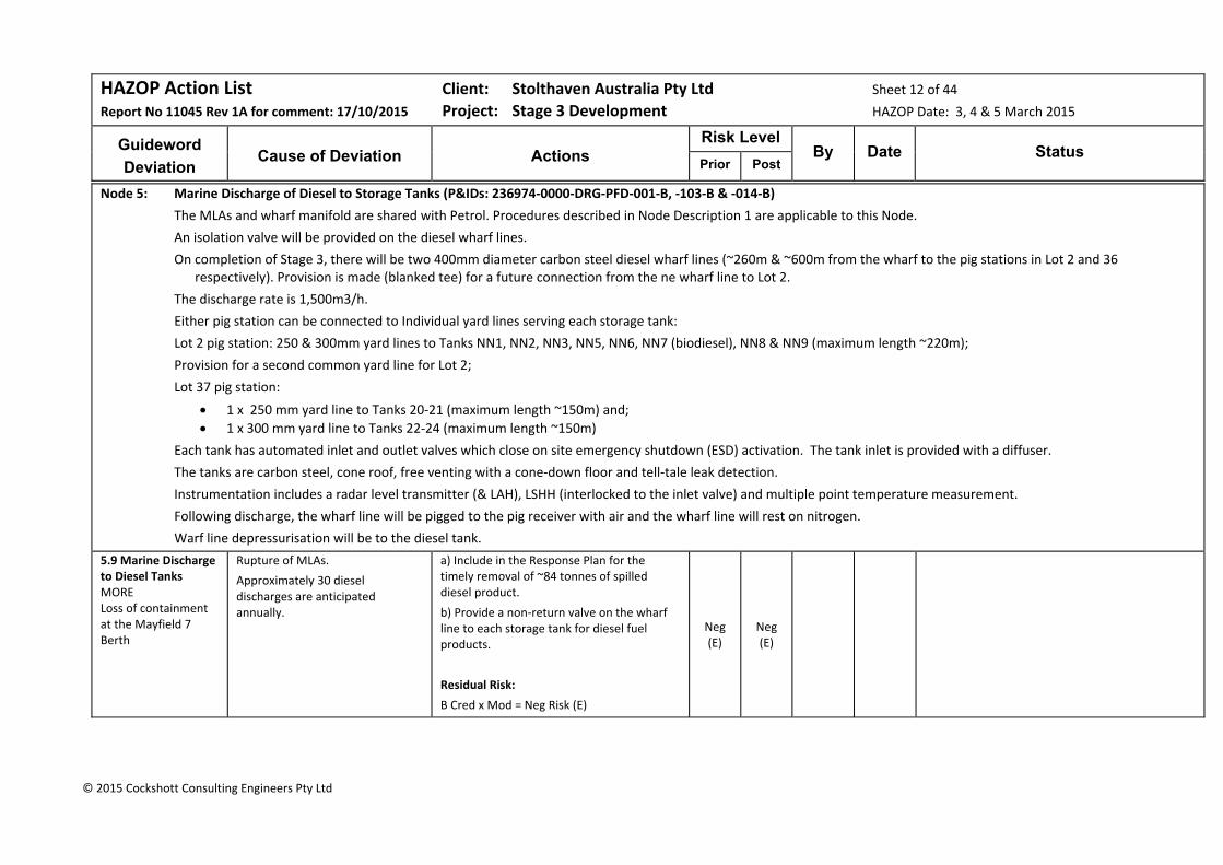
HAZOP Action List Client: Stolthaven Australia Pty Ltd Sheet 12 of 44
Report No 11045 Rev 1A for comment: 17/10/2015 Project: Stage 3 Development HAZOP Date: 3, 4 & 5 March 2015
Guideword
Deviation
Cause of Deviation
Actions
Risk Level By Date Status
Prior Post
© 2015 Cockshott Consulting Engineers Pty Ltd
Node 5: Marine Discharge of Diesel to Storage Tanks (P&IDs: 236974‐0000‐DRG‐PFD‐001‐B, ‐103‐B & ‐014‐B)
The MLAs and wharf manifold are shared with Petrol. Procedures described in Node Description 1 are applicable to this Node.
An isolation valve will be provided on the diesel wharf lines.
On completion of Stage 3, there will be two 400mm diameter carbon steel diesel wharf lines (~260m & ~600m from the wharf to the pig stations in Lot 2 and 36 respectively). Provision is made (blanked tee) for a future connection from the ne wharf line to Lot 2.
The discharge rate is 1,500m3/h.
Either pig station can be connected to Individual yard lines serving each storage tank:
Lot 2 pig station: 250 & 300mm yard lines to Tanks NN1, NN2, NN3, NN5, NN6, NN7 (biodiesel), NN8 & NN9 (maximum length ~220m);
Provision for a second common yard line for Lot 2;
Lot 37 pig station:
1 x 250 mm yard line to Tanks 20‐21 (maximum length ~150m) and;
1 x 300 mm yard line to Tanks 22‐24 (maximum length ~150m)
Each tank has automated inlet and outlet valves which close on site emergency shutdown (ESD) activation. The tank inlet is provided with a diffuser.
The tanks are carbon steel, cone roof, free venting with a cone‐down floor and tell‐tale leak detection.
Instrumentation includes a radar level transmitter (& LAH), LSHH (interlocked to the inlet valve) and multiple point temperature measurement.
Following discharge, the wharf line will be pigged to the pig receiver with air and the wharf line will rest on nitrogen.
Warf line depressurisation will be to the diesel tank.
5.9 Marine Discharge to Diesel Tanks MORE Loss of containment at the Mayfield 7 Berth
Rupture of MLAs.
Approximately 30 diesel discharges are anticipated annually.
a) Include in the Response Plan for the timely removal of ~84 tonnes of spilled diesel product.
b) Provide a non‐return valve on the wharf line to each storage tank for diesel fuel products.
Residual Risk:
B Cred x Mod = Neg Risk (E)
Neg (E)
Neg (E)
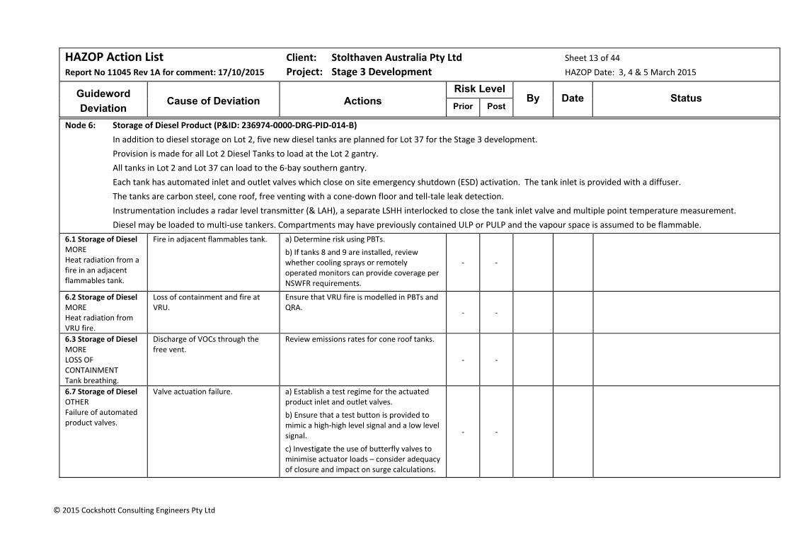
HAZOP Action List Client: Stolthaven Australia Pty Ltd Sheet 13 of 44
Report No 11045 Rev 1A for comment: 17/10/2015 Project: Stage 3 Development HAZOP Date: 3, 4 & 5 March 2015
Guideword
Deviation
Cause of Deviation
Actions
Risk Level By Date Status
Prior Post
© 2015 Cockshott Consulting Engineers Pty Ltd
Node 6: Storage of Diesel Product (P&ID: 236974‐0000‐DRG‐PID‐014‐B)
In addition to diesel storage on Lot 2, five new diesel tanks are planned for Lot 37 for the Stage 3 development.
Provision is made for all Lot 2 Diesel Tanks to load at the Lot 2 gantry.
All tanks in Lot 2 and Lot 37 can load to the 6‐bay southern gantry.
Each tank has automated inlet and outlet valves which close on site emergency shutdown (ESD) activation. The tank inlet is provided with a diffuser.
The tanks are carbon steel, cone roof, free venting with a cone‐down floor and tell‐tale leak detection.
Instrumentation includes a radar level transmitter (& LAH), a separate LSHH interlocked to close the tank inlet valve and multiple point temperature measurement.
Diesel may be loaded to multi‐use tankers. Compartments may have previously contained ULP or PULP and the vapour space is assumed to be flammable.
6.1 Storage of Diesel MORE Heat radiation from a fire in an adjacent flammables tank.
Fire in adjacent flammables tank. a) Determine risk using PBTs.
b) If tanks 8 and 9 are installed, review whether cooling sprays or remotely operated monitors can provide coverage per NSWFR requirements.
‐ ‐
6.2 Storage of Diesel MORE Heat radiation from VRU fire.
Loss of containment and fire at VRU.
Ensure that VRU fire is modelled in PBTs and QRA.
‐ ‐
6.3 Storage of Diesel MORE LOSS OF CONTAINMENT Tank breathing.
Discharge of VOCs through the free vent.
Review emissions rates for cone roof tanks.
‐ ‐
6.7 Storage of Diesel OTHER Failure of automated product valves.
Valve actuation failure. a) Establish a test regime for the actuated product inlet and outlet valves.
b) Ensure that a test button is provided to mimic a high‐high level signal and a low level signal.
c) Investigate the use of butterfly valves to minimise actuator loads – consider adequacy of closure and impact on surge calculations.
‐ ‐
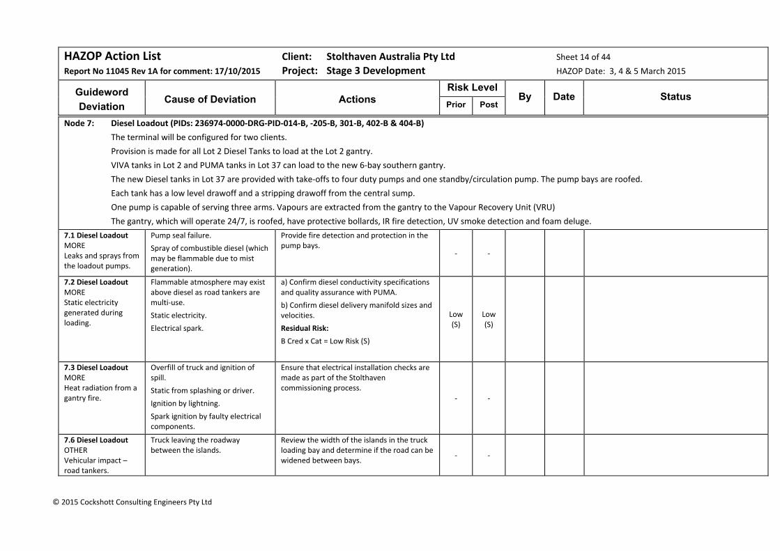
HAZOP Action List Client: Stolthaven Australia Pty Ltd Sheet 14 of 44
Report No 11045 Rev 1A for comment: 17/10/2015 Project: Stage 3 Development HAZOP Date: 3, 4 & 5 March 2015
Guideword
Deviation
Cause of Deviation
Actions
Risk Level By Date Status
Prior Post
© 2015 Cockshott Consulting Engineers Pty Ltd
Node 7: Diesel Loadout (PIDs: 236974‐0000‐DRG‐PID‐014‐B, ‐205‐B, 301‐B, 402‐B & 404‐B)
The terminal will be configured for two clients.
Provision is made for all Lot 2 Diesel Tanks to load at the Lot 2 gantry.
VIVA tanks in Lot 2 and PUMA tanks in Lot 37 can load to the new 6‐bay southern gantry.
The new Diesel tanks in Lot 37 are provided with take‐offs to four duty pumps and one standby/circulation pump. The pump bays are roofed.
Each tank has a low level drawoff and a stripping drawoff from the central sump.
One pump is capable of serving three arms. Vapours are extracted from the gantry to the Vapour Recovery Unit (VRU)
The gantry, which will operate 24/7, is roofed, have protective bollards, IR fire detection, UV smoke detection and foam deluge.
7.1 Diesel Loadout MORE Leaks and sprays from the loadout pumps.
Pump seal failure.
Spray of combustible diesel (which may be flammable due to mist generation).
Provide fire detection and protection in the pump bays.
‐ ‐
7.2 Diesel Loadout MORE Static electricity generated during loading.
Flammable atmosphere may exist above diesel as road tankers are multi‐use.
Static electricity.
Electrical spark.
a) Confirm diesel conductivity specifications and quality assurance with PUMA.
b) Confirm diesel delivery manifold sizes and velocities.
Residual Risk:
B Cred x Cat = Low Risk (S)
Low (S)
Low (S)
7.3 Diesel Loadout MORE Heat radiation from a gantry fire.
Overfill of truck and ignition of spill.
Static from splashing or driver.
Ignition by lightning.
Spark ignition by faulty electrical components.
Ensure that electrical installation checks are made as part of the Stolthaven commissioning process.
‐ ‐
7.6 Diesel Loadout OTHER Vehicular impact – road tankers.
Truck leaving the roadway between the islands.
Review the width of the islands in the truck loading bay and determine if the road can be widened between bays.
‐ ‐

HAZOP Action List Client: Stolthaven Australia Pty Ltd Sheet 15 of 44
Report No 11045 Rev 1A for comment: 17/10/2015 Project: Stage 3 Development HAZOP Date: 3, 4 & 5 March 2015
Guideword
Deviation
Cause of Deviation
Actions
Risk Level By Date Status
Prior Post
© 2015 Cockshott Consulting Engineers Pty Ltd
7.8 Diesel Loadout MORE LOSS OF CONTAINMENT Gantry
Spill of tanker compartment. Review when details of the remote impounding basin are developed.
‐ ‐
Node 9: Marine Discharge of Jet Fuel to Storage Tank (Piping routing drawings 030 series Rev B, 236974‐0000‐DRG‐PFD‐001‐A & P&IDs 236974‐0000‐DRG‐P&ID‐013/104‐A)
A single 200mm SCH 10S stainless steel jet fuel wharf line (~440m length) is provided from the wharf to the pig stations in Lot 36.
Jet fuel has a lower vapour pressure than gasoline < 0.1 kPa) and has a flash point >38°C.
A single 200mm SCH 10S stainless steel yard line is connected to T26, which is a lined tank with stainless steel internals. T26 is located in a bund containing other flammable products (petrol and ethanol)
With a discharge rate through the wharf line of 350m3/h, the fluid velocity is 3.0 m/s.
The jet fuel tank has automated inlet and outlet valves which close on site emergency shutdown (ESD) activation. . The tank inlet is provided with a diffuser.
The tank is a free‐venting cone roof tank which has a floating suction. Sample points are provided at various levels (attached to the floating suction).
The tank has a cone‐down floor and is provided with tell‐tale leak detection. Instrumentation includes a radar level transmitter (LAH), separate LSHH interlocked to the automated tank inlet valve and multiple point temperature measurement.
Following discharge, the wharf line will be cleared to the pig receiver so that the wharf piping rests on nitrogen.
The yard piping will rest on product.
9.2 Discharge of Jet Fuel to Storage Tank MORE Static electricity
Flammable/Explosive materials:
Jet fuel.
Potential for flammable vapours in the storage tank vapour space.
Sources of Ignition:
Static generation during discharge.
Confirm jet fuel conductivity specifications and quality assurance with customer.
Residual Risk:
N Cred x Cat = Low Risk (S) Low (S)
Low (S)
9.3 Discharge of Jet Fuel to Storage Tank MORE Heat radiation from a gantry fire.
Fire in adjacent gantry. Determine gantry fire knock‐on to neighbouring tanks in consequence analysis and in PBTs. ‐ ‐
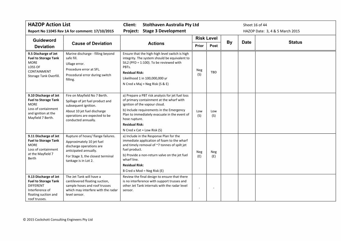
HAZOP Action List Client: Stolthaven Australia Pty Ltd Sheet 16 of 44
Report No 11045 Rev 1A for comment: 17/10/2015 Project: Stage 3 Development HAZOP Date: 3, 4 & 5 March 2015
Guideword
Deviation
Cause of Deviation
Actions
Risk Level By Date Status
Prior Post
© 2015 Cockshott Consulting Engineers Pty Ltd
9.5 Discharge of Jet Fuel to Storage Tank MORE LOSS OF CONTAINMENT Storage Tank Overfill.
Marine discharge ‐ filling beyond safe fill.
Ullage error.
Procedure error at SFL.
Procedural error during switch filling.
Ensure that the high‐high level switch is high integrity. The system should be equivalent to SIL2 (PFD = 1:100). To be reviewed with PBTs.
Residual Risk:
Likelihood 1 in 100,000,000 yr
N Cred x Maj = Neg Risk (S & E)
Neg (S)
TBD
9.10 Discharge of Jet Fuel to Storage Tank MORE Loss of containment and ignition at the Mayfield 7 Berth.
Fire on Mayfield No 7 Berth.
Spillage of jet fuel product and subsequent ignition.
About 10 jet fuel discharge operations are expected to be conducted annually.
a) Prepare a PBT risk analysis for jet fuel loss of primary containment at the wharf with ignition of the vapour cloud.
b) Include requirements in the Emergency Plan to immediately evacuate in the event of hose rupture.
Residual Risk:
N Cred x Cat = Low Risk (S)
Low (S)
Low (S)
9.11 Discharge of Jet Fuel to Storage Tank MORE Loss of containment at the Mayfield 7 Berth
Rupture of hoses/ flange failures.
Approximately 10 jet fuel discharge operations are anticipated annually.
For Stage 3, the closest terminal tankage is in Lot 2.
a) Include in the Response Plan for the immediate application of foam to the wharf and timely removal of ~7 tonnes of spilt jet fuel product.
b) Provide a non‐return valve on the jet fuel wharf line.
Residual Risk:
B Cred x Mod = Neg Risk (E)
Neg (E)
Neg (E)
9.13 Discharge of Jet Fuel to Storage Tank DIFFERENT Interference of floating suction and roof trusses.
The Jet Tank will have a cantilevered floating suction, sample hoses and roof trusses which may interfere with the radar level sensor.
Review the final design to ensure that there is no interference with support trusses and other Jet Tank internals with the radar level sensor.
‐ ‐
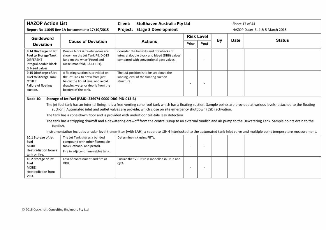
HAZOP Action List Client: Stolthaven Australia Pty Ltd Sheet 17 of 44
Report No 11045 Rev 1A for comment: 17/10/2015 Project: Stage 3 Development HAZOP Date: 3, 4 & 5 March 2015
Guideword
Deviation
Cause of Deviation
Actions
Risk Level By Date Status
Prior Post
© 2015 Cockshott Consulting Engineers Pty Ltd
9.14 Discharge of Jet Fuel to Storage Tank DIFFERENT Integral double block & bleed valves.
Double block & cavity valves are shown on the Jet Tank P&ID‐013 (and on the wharf Petrol and Diesel manifold, P&ID‐101).
Consider the benefits and drawbacks of integral double block and bleed (DBB) valves compared with conventional gate valves. ‐ ‐
9.15 Discharge of Jet Fuel to Storage Tank OTHER Failure of floating suction.
A floating suction is provided on the Jet Tank to draw from just below the liquid level and avoid drawing water or debris from the bottom of the tank.
The LAL position is to be set above the landing level of the floating suction structure.
‐ ‐
Node 10: Storage of Jet Fuel (P&ID: 236974‐0000‐DRG‐PID‐013‐B)
The jet fuel tank has an internal lining. It is a free‐venting cone roof tank which has a floating suction. Sample points are provided at various levels (attached to the floating suction). Automated inlet and outlet valves are provide, which close on site emergency shutdown (ESD) activation.
The tank has a cone‐down floor and is provided with underfloor tell‐tale leak detection.
The tank has a stripping drawoff and a dewatering drawoff from the central sump to an external tundish and air pump to the Dewatering Tank. Sample points drain to the tundish.
Instrumentation includes a radar level transmitter (with LAH), a separate LSHH interlocked to the automated tank inlet valve and multiple point temperature measurement.
10.1 Storage of Jet Fuel MORE Heat radiation from a tank on fire.
The Jet Tank shares a bunded compound with other flammable tanks (ethanol and petrol).
Fire in adjacent flammables tank.
Determine risk using PBTs.
‐ ‐
10.2 Storage of Jet Fuel MORE Heat radiation from VRU.
Loss of containment and fire at VRU.
Ensure that VRU fire is modelled in PBTs and QRA.
‐ ‐
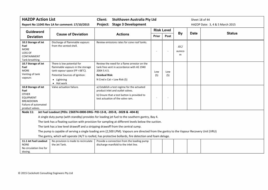
HAZOP Action List Client: Stolthaven Australia Pty Ltd Sheet 18 of 44
Report No 11045 Rev 1A for comment: 17/10/2015 Project: Stage 3 Development HAZOP Date: 3, 4 & 5 March 2015
Guideword
Deviation
Cause of Deviation
Actions
Risk Level By Date Status
Prior Post
© 2015 Cockshott Consulting Engineers Pty Ltd
10.5 Storage of Jet Fuel MORE LOSS OF CONTAINMENT Tank breathing.
Discharge of flammable vapours from the vented shell.
Review emissions rates for cone roof tanks.
‐ ‐
JEC/
aurecom
10.7 Storage of Jet Fuel MORE Venting of tank vapours
There is low potential for flammable vapours in the storage tank vapour space (FP >38°C).
Potential Sources of Ignition:
Lightning
Hot work
Review the need for a flame arrestor on the tank free vent in accordance with AS 1940 2004 5.4.5.
Residual Risk:
N Cred x Cat = Low Risk (S)
Low (S)
Low (S)
10.8 Storage of Jet Fuel OTHER EQUIPMENT BREAKDOWN Failure of automated product valves.
Valve actuation failure. a) Establish a test regime for the actuated product inlet and outlet valves.
b) Ensure that a test button is provided to test actuation of the valve ram. ‐ ‐
Node 11: Jet Fuel Loadout (PIDs: 236974‐0000‐DRG‐ PID‐13‐B, ‐203‐B, ‐302B & ‐404‐B)
A single duty pump (with standby) provides for loading jet fuel to the southern gantry, Bay 4.
The tank has a floating suction with provision for sampling at different levels below the suction.
The tank has a low level drawoff and a stripping drawoff from the central sump.
The pump is capable of serving a single loading arm (2,500 LPM). Vapours are directed from the gantry to the Vapour Recovery Unit (VRU)
The gantry, which will operate 24/7 is roofed, has protective bollards, fire detection and foam deluge.
11.1 Jet Fuel Loadout NONE No circulation line for dosing.
No provision is made to recirculate the Jet Tank.
Provide a connection from the loading pump discharge manifold to the inlet line.
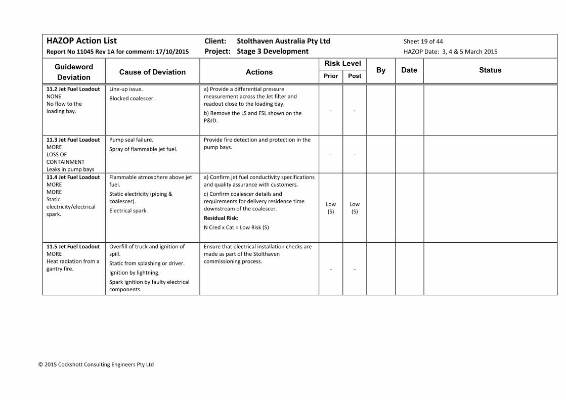
HAZOP Action List Client: Stolthaven Australia Pty Ltd Sheet 19 of 44
Report No 11045 Rev 1A for comment: 17/10/2015 Project: Stage 3 Development HAZOP Date: 3, 4 & 5 March 2015
Guideword
Deviation
Cause of Deviation
Actions
Risk Level By Date Status
Prior Post
© 2015 Cockshott Consulting Engineers Pty Ltd
11.2 Jet Fuel Loadout NONE No flow to the loading bay.
Line‐up issue.
Blocked coalescer.
a) Provide a differential pressure measurement across the Jet filter and readout close to the loading bay.
b) Remove the LS and FSL shown on the P&ID.
‐ ‐
11.3 Jet Fuel Loadout MORE LOSS OF CONTAINMENT Leaks in pump bays
Pump seal failure.
Spray of flammable jet fuel.
Provide fire detection and protection in the pump bays.
‐ ‐
11.4 Jet Fuel Loadout MORE MORE Static electricity/electrical spark.
Flammable atmosphere above jet fuel.
Static electricity (piping & coalescer).
Electrical spark.
a) Confirm jet fuel conductivity specifications and quality assurance with customers.
c) Confirm coalescer details and requirements for delivery residence time downstream of the coalescer.
Residual Risk:
N Cred x Cat = Low Risk (S)
Low (S)
Low (S)
11.5 Jet Fuel Loadout MORE Heat radiation from a gantry fire.
Overfill of truck and ignition of spill.
Static from splashing or driver.
Ignition by lightning.
Spark ignition by faulty electrical components.
Ensure that electrical installation checks are made as part of the Stolthaven commissioning process.
‐ ‐

HAZOP Action List Client: Stolthaven Australia Pty Ltd Sheet 20 of 44
Report No 11045 Rev 1A for comment: 17/10/2015 Project: Stage 3 Development HAZOP Date: 3, 4 & 5 March 2015
Guideword
Deviation
Cause of Deviation
Actions
Risk Level By Date Status
Prior Post
© 2015 Cockshott Consulting Engineers Pty Ltd
11.7 Jet Fuel Loadout MORE Leakage of coalescer auto air eliminator.
P&ID shows a manual air elimination arrangement.
a) Thee manual air elimination arrangements shown on the P&ID is preferred. (Note: If an automatic air eliminator is subsequently provided, provide a permanent tundish visible to the driver loading Jet).
b) Provide upstream and downstream isolation valves to permit maintenance of the coalescer.
‐ ‐
11.8 Jet Fuel Loadout MORE Pressure
VSD on Jet service and standby pumps.
Remove the Jet Pumps’ VSD. ‐ ‐
11.9 Jet Fuel Loadout MORE Complexity
Control error.
Flow switch low (FSL) failure.
For all Stage 3 pumps:
Replace the FSL detection and interlocks with low current detection and interlocks.
‐ ‐
11.10 Jet Fuel Loadout MORE LOSS OF CONTAINMENT Pump bay leaks..
Valve, gasket or seal leakage. Provide a blind sump in the pump bay bund and equip this with a float valve. Determine the action taken on high level activation.
‐ ‐
11.11 Jet Fuel Loadout MORE LOSS OF CONTAINMENT Gantry
Spill of tanker compartment. Review when details of the remote impounding basin are developed.
‐ ‐
11.12 Jet Fuel Loadout DIFFERENT Cross contamination.
The air eliminator in Loading Bay 4 discharges to a common line (petrol, diesel and ethanol) to the Bay 4 drip tray.
Ensure that the Jet Fuel air eliminator in Loading Bay 4 discharges directly to the drip tray and is not manifolded with other product air eliminator discharges.
‐ ‐
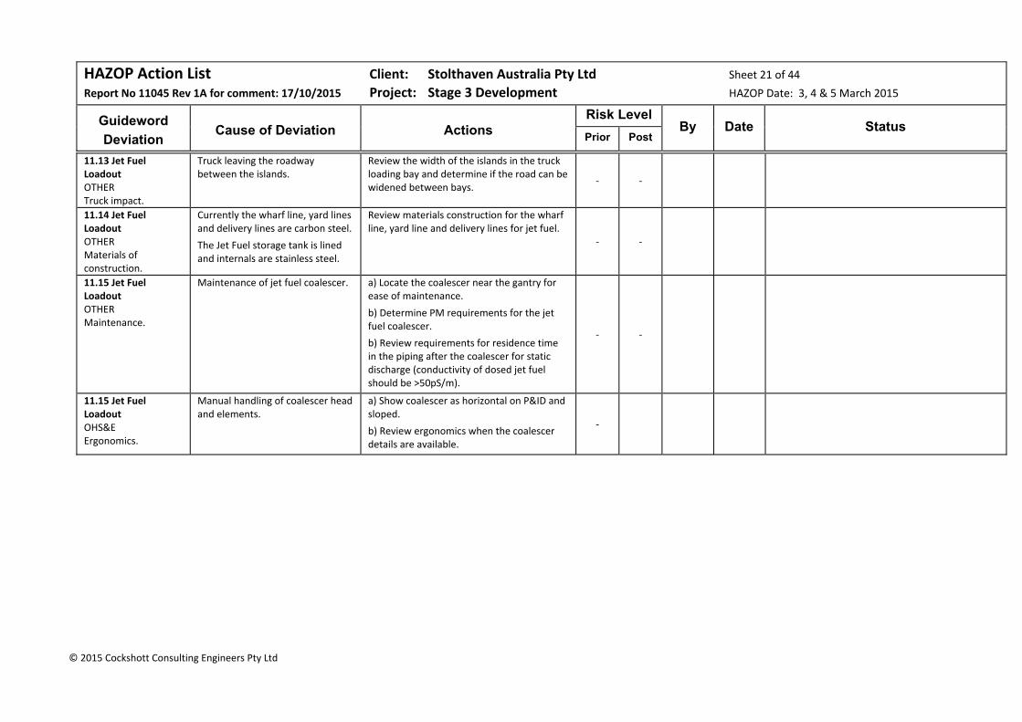
HAZOP Action List Client: Stolthaven Australia Pty Ltd Sheet 21 of 44
Report No 11045 Rev 1A for comment: 17/10/2015 Project: Stage 3 Development HAZOP Date: 3, 4 & 5 March 2015
Guideword
Deviation
Cause of Deviation
Actions
Risk Level By Date Status
Prior Post
© 2015 Cockshott Consulting Engineers Pty Ltd
11.13 Jet Fuel Loadout OTHER Truck impact.
Truck leaving the roadway between the islands.
Review the width of the islands in the truck loading bay and determine if the road can be widened between bays.
‐ ‐
11.14 Jet Fuel Loadout OTHER Materials of construction.
Currently the wharf line, yard lines and delivery lines are carbon steel.
The Jet Fuel storage tank is lined and internals are stainless steel.
Review materials construction for the wharf line, yard line and delivery lines for jet fuel.
‐ ‐
11.15 Jet Fuel Loadout OTHER Maintenance.
Maintenance of jet fuel coalescer. a) Locate the coalescer near the gantry for ease of maintenance.
b) Determine PM requirements for the jet fuel coalescer.
b) Review requirements for residence time in the piping after the coalescer for static discharge (conductivity of dosed jet fuel should be >50pS/m).
‐ ‐
11.15 Jet Fuel Loadout OHS&E Ergonomics.
Manual handling of coalescer head and elements.
a) Show coalescer as horizontal on P&ID and sloped.
b) Review ergonomics when the coalescer details are available.
‐

HAZOP Action List Client: Stolthaven Australia Pty Ltd Sheet 22 of 44
Report No 11045 Rev 1A for comment: 17/10/2015 Project: Stage 3 Development HAZOP Date: 3, 4 & 5 March 2015
Guideword
Deviation
Cause of Deviation
Actions
Risk Level By Date Status
Prior Post
© 2015 Cockshott Consulting Engineers Pty Ltd
Node 12: Marine Discharge of Ethanol to Storage Tank (P&IDs: 236974‐0000‐DRG‐‐P&ID‐101‐B, 104‐B & 012‐B)
A single dedicated 200mm carbon steel ethanol wharf line (~440m length) is provided from the wharf to the pig stations in Lot 36.
Ethanol has a lower vapour pressure than gasoline (~8 kPa vs 62‐80 kPa) and has a flash point of 9°C. The discharge rate for the ethanol is 350m3/h.
A single 200mm yard line is connected from the pig receiver to Tank T25.
With a discharge rate through the wharf line of 350m3/h, the fluid velocity is 3.0m/s.
The ethanol tank has automated inlet and outlet valves which close on site emergency shutdown (ESD) activation. The tank inlet is provided with a diffuser.
The P&ID shows an Internal Floating Roof (IFR) tank with recirculation. For the HAZOP, it was agreed that the tank is most likely to be a low pressure (API 620 Appendix F) to minimise loss to the air environment. The recirculation line will be deleted.
Each tank has a cone‐down floor and is provided with tell‐tale leak detection.
Instrumentation will include a pressure control valve for vapours, a relief valve and an emergency vent, a radar level transmitter (LAH), separate LSHH interlocked to the tank inlet valve and multiple point temperature measurement.
Following discharge, wharf piping will be cleared to the VRU and the yard piping will be cleared to the tank. The lines will rest on nitrogen.
The yard piping will rest on product.
12.1 Marine Discharge of Ethanol to Storage MORE Static electricity – wharf lines.
Flammable/Explosive materials:
Ethanol.
Residual vapour in wharf line from the berth to the terminal isolation valve, following pigging to the pig receiver with nitrogen.
Sources of Ignition:
Static generation during discharge;
Lightning.
a) Provide an isolation valve shore‐side on the ethanol line.
b) Review the proposed procedure to remove product from the over‐water section of the ethanol wharf lines. Determine if air or nitrogen is used to clear the wharf line to the terminal valve.
c) If air is used to clear the over‐water lines, determine how this is cleared for the next discharge.
Residual Risk:
N Cred x Maj = Neg Risk (S)
Neg (S)
Neg (S)
HAZOP Action List Client: Stolthaven Australia Pty Ltd Sheet 23 of 44
Report No 11045 Rev 1A for comment: 17/10/2015 Project: Stage 3 Development HAZOP Date: 3, 4 & 5 March 2015
Guideword
Deviation
Cause of Deviation
Actions
Risk Level By Date Status
Prior Post
© 2015 Cockshott Consulting Engineers Pty Ltd
12.3 Marine Discharge of Ethanol to Storage MORE Heat radiation from a gantry fire.
Fire in adjacent gantry. Determine gantry fire knock‐on from the ethanol tank to neighbouring tanks in consequence analysis and in PBTs.
‐ ‐
12.5 Marine Discharge of Ethanol to Storage MORE LOSS OF CONTAINMENT Storage Tank Overfill.
Marine discharge ‐ filling beyond safe fill.
Ullage error.
Procedure error at SFL.
Include a test for ethanol for water in the sub‐compounds in the ethanol bund.
Residual Risk:
N Cred x Maj = Neg Risk (S & E)
Neg (S&E)
Neg (S&E)
12.7 Marine Discharge of Ethanol to Storage MORE Overpressure from ammonium nitrate explosion in port or heat radiation from coal carrier at berth in the channel.
Combustible/Explosive materials:
K2 Berth: bulk ammonium nitrate (2 km).
M4 Berth: packaged ammonium nitrate (1 km).
Coal Bulk Carriers (200m from M7).
Sources of Ignition:
On‐board fire on ammonium nitrate ship at K2;
Contamination of ammonium nitrate with organic materials;
Coal fire in Coal bulk carrier hold.
a) Operations should be halted for any event at the Ammonium Nitrate manufacturing facility (e.g. fire or ammonia release) or cargo fire on a bulk coal carrier.
Residual Risk:
E Rare x Min = Neg Risk (S) Neg (S)
Neg (S)
HAZOP Action List Client: Stolthaven Australia Pty Ltd Sheet 24 of 44
Report No 11045 Rev 1A for comment: 17/10/2015 Project: Stage 3 Development HAZOP Date: 3, 4 & 5 March 2015
Guideword
Deviation
Cause of Deviation
Actions
Risk Level By Date Status
Prior Post
© 2015 Cockshott Consulting Engineers Pty Ltd
12.9 Marine Discharge of Ethanol to Storage MORE Loss of containment and ignition at the Mayfield 7 Berth.
Spillage of flammable product and subsequent ignition.
Ignition of vapours by non‐rated vehicles or hot work.
About 10 ethanol discharge operations are expected to be conducted annually.
For Stage 3, the closest terminal tankage is in Lot 2.
a) Prepare a PBT risk analysis for ethanol loss of primary containment at the wharf with ignition of the vapour cloud.
b) Include requirements in the Emergency Plan to immediately evacuate in the event of hose rupture.
Residual Risk:
N Cred x Cat = Low Risk (S)
Low (S)
Low (S)
12.10 Discharge of Ethanol to Storage Tank MORE Loss of containment at the Mayfield 7 Berth
Rupture of hoses/ flange failures.
Approximately 10 ethanol discharge operations are anticipated annually.
For Stage 3, the closest terminal tankage is in Lot 2.
a) Include in the Response Plan for the immediate application of foam to the wharf and timely removal of ~7 tonnes of spilt ethanol.
b) Provide a non‐return valve on the ethanol wharf line.
Residual Risk:
B Cred x Mod = Neg Risk (E)
Neg (S)
Neg (S)
Node 13: Storage of Ethanol (P&ID: 236974‐0000‐DRG‐PID‐012‐B)
The P&ID shows an Internal Floating Roof (IFR) tank with recirculation. For the HAZOP, it was agreed that the tank is most likely to be a low pressure (API 620 Appendix F) to minimise loss to the air environment. The recirculation line will be deleted. The air scoops are deleted
The dewatering system show on the P&ID has been removed for the purposes of the HAZOP.
The ethanol tank has automated inlet and outlet valves which close on site emergency shutdown (ESD) activation. The inlet valve is interlocked with the LSHH.
The tank is a free‐venting cone roof tank with a cone‐down floor and is provided with underfloor tell‐tale leak detection.
The tank has a stripping drawoff from the central sump.
Instrumentation includes a radar level transmitter (with LAH), a separate LSHH interlocked to the automated tank inlet valve and multiple point temperature measurement.
13.1 Storage of Ethanol MORE Heat radiation from tank‐on‐fire
Fire in adjacent flammables tank. Determine risk using PBTs.
HAZOP Action List Client: Stolthaven Australia Pty Ltd Sheet 25 of 44
Report No 11045 Rev 1A for comment: 17/10/2015 Project: Stage 3 Development HAZOP Date: 3, 4 & 5 March 2015
Guideword
Deviation
Cause of Deviation
Actions
Risk Level By Date Status
Prior Post
© 2015 Cockshott Consulting Engineers Pty Ltd
13.2 Storage of Ethanol DIFFERENT Emissions to air for IFR and low pressure tanks.
The final decision has not been made as to whether the ethanol tank should be an IFR tank or a low pressure tank.
Review emissions rates for IFR and low pressure (API 620 Appendix F) cone roof tanks
‐ ‐ JEC/
JH 18/3/15
Screening study 11045‐1 Rev A completed 18/03/2015.
Awaiting decision.
13.4 Storage of Ethanol DIFFERENT Import by road tanker.
The design only provides for import by ship.
Determine if facilities for road tanker importation should be provided for ethanol.
‐ ‐
13.7 Storage of Ethanol LOSS OF CONTAINMENT Tank breathing.
Vapours in the ethanol tank will be within explosive limits.
Discharge of flammable vapours from the vented shell.
Potential Sources of Ignition:
Lightning
Hot work
Provide a flame arrestor on the free vent of the ethanol tank in accordance with AS 1940 2004 5.4.5.
B Cred x Cat = Low Risk (S)
‐ ‐
13.8 Storage of Ethanol EQUIPMENT BREAKDOWN Failure of automated product valves.
Valve actuation failure. a) Establish a test regime for the actuated product inlet and outlet valves.
b) Ensure that a test button is provided to test actuation of the valve ram.
‐ ‐
13.9 Storage of Ethanol OTHER Failure of automated product valves.
Valve actuation failure. Apply Actions 2.13 a/b/c to the ethanol tank.
‐ ‐
HAZOP Action List Client: Stolthaven Australia Pty Ltd Sheet 26 of 44
Report No 11045 Rev 1A for comment: 17/10/2015 Project: Stage 3 Development HAZOP Date: 3, 4 & 5 March 2015
Guideword
Deviation
Cause of Deviation
Actions
Risk Level By Date Status
Prior Post
© 2015 Cockshott Consulting Engineers Pty Ltd
Node 14: Ethanol Loadout (P&IDs: 236974‐0000‐DRG‐ PID‐012‐B, 203‐B, 302‐B, 401‐B, 402‐B, 403‐B & 404‐B)
Ethanol will be loaded to one arm each bay in the southern 4‐bay gantry as a fuel additive.
The tank has a low level drawoff to dedicated duty & assist delivery pumps (rotary vane) to a single delivery manifold. The pump bay is roofed.
The tank also has a stripping drawoff from the central sump.
One pump is capable of serving three arms. The assist pump is automatically started as required. Vapours are returned from the gantry to the Vapour Recovery Unit (VRU)
The gantries, which will operate 24/7 are roofed, have protective bollards, fire detection and foam deluge.
14.1 Ethanol Loadout NONE No flow of ethanol to the gantry.
Ethanol is not delivered during initial compartment loading or at the end (final petrol flush).
a) Review how the ethanol sliding vane pump can operate as petrol additive pump with the fuel management system without high pressure during no flow operation.
b) Consider a centrifugal pump as an alternative for ethanol loadout. (For a centrifugal pump, the FSL can be replaced with a low current interlock).
‐ ‐
14.2 Ethanol Loadout NONE E20 cannot be loaded.
The pump capacity has been selected to load E10.
Determine if the ethanol loadout pump should be specified with the ability to load out E20. ‐ ‐
14.3 Ethanol Loadout MORE Loss of containment in the loading bays.
Hose disconnection.
Road tanker valves open.
Review the detection system in the gantry sump (not shown on P&IDs). The detection system should take account of water and all products – petrol (flammable), ethanol (flammable, miscible with water), jet (high flash point flammable) and diesel (combustible).
‐ ‐
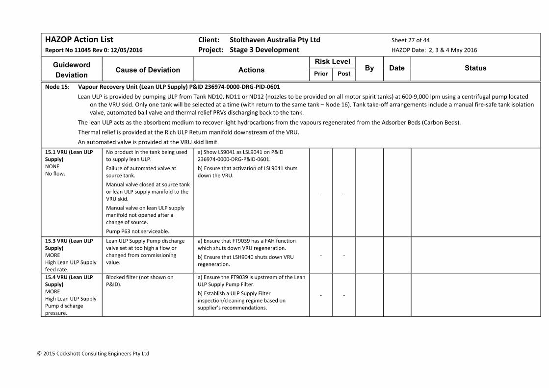
HAZOP Action List Client: Stolthaven Australia Pty Ltd Sheet 27 of 44
Report No 11045 Rev 0: 12/05/2016 Project: Stage 3 Development HAZOP Date: 2, 3 & 4 May 2016
Guideword
Deviation
Cause of Deviation
Actions
Risk Level By Date Status
Prior Post
© 2015 Cockshott Consulting Engineers Pty Ltd
Node 15: Vapour Recovery Unit (Lean ULP Supply) P&ID 236974‐0000‐DRG‐PID‐0601
Lean ULP is provided by pumping ULP from Tank ND10, ND11 or ND12 (nozzles to be provided on all motor spirit tanks) at 600‐9,000 lpm using a centrifugal pump located on the VRU skid. Only one tank will be selected at a time (with return to the same tank – Node 16). Tank take‐off arrangements include a manual fire‐safe tank isolation valve, automated ball valve and thermal relief PRVs discharging back to the tank.
The lean ULP acts as the absorbent medium to recover light hydrocarbons from the vapours regenerated from the Adsorber Beds (Carbon Beds).
Thermal relief is provided at the Rich ULP Return manifold downstream of the VRU.
An automated valve is provided at the VRU skid limit.
15.1 VRU (Lean ULP Supply) NONE No flow.
No product in the tank being used to supply lean ULP.
Failure of automated valve at source tank.
Manual valve closed at source tank or lean ULP supply manifold to the VRU skid.
Manual valve on lean ULP supply manifold not opened after a change of source.
Pump P63 not serviceable.
a) Show LS9041 as LSL9041 on P&ID 236974‐0000‐DRG‐P&ID‐0601.
b) Ensure that activation of LSL9041 shuts down the VRU.
‐ ‐
15.3 VRU (Lean ULP Supply) MORE High Lean ULP Supply feed rate.
Lean ULP Supply Pump discharge valve set at too high a flow or changed from commissioning value.
a) Ensure that FT9039 has a FAH function which shuts down VRU regeneration.
b) Ensure that LSH9040 shuts down VRU regeneration.
‐ ‐
15.4 VRU (Lean ULP Supply) MORE High Lean ULP Supply Pump discharge pressure.
Blocked filter (not shown on P&ID).
a) Ensure the FT9039 is upstream of the Lean ULP Supply Pump Filter.
b) Establish a ULP Supply Filter inspection/cleaning regime based on supplier’s recommendations.
‐ ‐

HAZOP Action List Client: Stolthaven Australia Pty Ltd Sheet 28 of 44
Report No 11045 Rev 0: 12/05/2016 Project: Stage 3 Development HAZOP Date: 2, 3 & 4 May 2016
Guideword
Deviation
Cause of Deviation
Actions
Risk Level By Date Status
Prior Post
© 2015 Cockshott Consulting Engineers Pty Ltd
15.6 VRU (Lean ULP Supply) MORE LOSS OF CONTAINMENT Leak/spray from pump seal
Lean ULP Supply Pump seal failure. a) Determine VRU Bund gas detector functionality, alarm and shutdown settings in SIL/SFARP study.
b) Consider specifying sealless (mag drive) pumps for Lean ULP Supply and Rich ULP Return Pump duties.
‐ ‐
15.7 Ethanol Loadout MORE High pressure in the ULP piping
Solar radiation on exposed lean ULP supply piping.
Ensure that the setting of thermal relief valves is sufficiently high to prevent flow except for thermal relief conditions to protect piping.
‐ ‐
15.9 VRU (Lean ULP Supply) OTHER Maintenance
Failure of Lean ULP Supply Pump. Review critical spares for all VRU equipment. Determine if both ULP Supply and Return Pumps can be identical.
‐ ‐
15.10 VRU (Lean ULP Supply) OTHER Sampling
The performance of the VRU will need to be monitored from time to time to satisfy EPA requirements.
Ensure that proper sampling points are provided for all VRU liquid and gas samples – two valves, pointing away from operator and ergonomic.
‐ ‐

HAZOP Action List Client: Stolthaven Australia Pty Ltd Sheet 29 of 44
Report No 11045 Rev 0: 12/05/2016 Project: Stage 3 Development HAZOP Date: 2, 3 & 4 May 2016
Guideword
Deviation
Cause of Deviation
Actions
Risk Level By Date Status
Prior Post
© 2015 Cockshott Consulting Engineers Pty Ltd
Node 16: Vapour Recovery Unit (Rich ULP Return) P&ID 236974‐0000‐DRG‐PID‐0601
The rich ULP is returned from the base of the Absorber by centrifugal pump P66 under level control back to the source tank. The return nozzle is opposite the lean ULP supply nozzle and has similar arrangement with a manual fire‐safe tank isolation valve, automated ball valve and thermal relief PRVs discharging back to the tank.
The Rich ULP pump will either have speed control or be provided with a downstream control valve.
An automated valve is provided at the VRU skid limit.
16.1 VRU (Rich ULP Return) NONE No level in the base of the Absorber.
Level control failure.
Loss of lean ULP feed to Absorber.
a) Consider magnetic drive pumps for this application.
b) Ensure that the level control system is of high reliability.
c) Ensure that the interlocks on the Absorber Low Level, LSL9041, and Rich ULP Pump Low Flow, FT9043 are independent and provide a risk reduction factor (RRF) of 1,000 to 10,000. Review this in the SIL/SFARP Study.
Residual Risk:
B Cred x Cat = Low Risk (S)
Sig (S)
Low (S)
16.2 VRU (Rich ULP Return) No flow of rich ULP return.
Pump P66 failure.
Control failure (pump P66 stopped or downstream control valve closed).
a) Ensure that Carbon Bed breakthrough detection shuts down the VRU.
b) Ensure that LSL0141 is independent of the level control system.
‐ ‐
16.4 VRU (Rich ULP Return) MORE High pressure in ULP return piping.
Solar radiation on exposed rich ULP return piping.
Ensure that the setting of thermal relief valves is sufficiently high to avoid flow except for thermal relief conditions to protect piping.
‐ ‐

HAZOP Action List Client: Stolthaven Australia Pty Ltd Sheet 30 of 44
Report No 11045 Rev 0: 12/05/2016 Project: Stage 3 Development HAZOP Date: 2, 3 & 4 May 2016
Guideword
Deviation
Cause of Deviation
Actions
Risk Level By Date Status
Prior Post
© 2015 Cockshott Consulting Engineers Pty Ltd
16.5 VRU (Rich ULP Return) DIFFERENT Different volatilities of ULP.
The vapour pressure of motor spirit will vary depending on the season. This will impact on the vapours from the gantry and the performance of the lean ULP to recover regenerated hydrocarbons.
Calculate the impact on the VRU recovery of variations in the volatility of ULP and PULP.
‐ ‐
Node 17: Vapour Recovery Unit (Vapours from Lots 2 & 36) P&ID 236974‐0000‐DRG‐PID‐0601
Vapours rich in light hydrocarbons are fed to the on‐stream Carbon Bed Adsorber through a liquid knock‐out pot.
Lean vapours exit from the top of the carbon bed to the atmosphere. Exhaust is continuously monitored for EPA compliance and flammability. The on‐stream bed is switched to regeneration when it has become sufficiently saturated.
17.1 VRU (Vapours) NONE No flow of rich petrol vapour from the gantry.
No trucks filling (no consequence).
Valve closed in the vapour line to the Carbon Bed.
Provide a pressure transmitter in the VRU inlet header to alarm in the event of excessive pressure (lower than PRV9034 set pressure).
‐ ‐
17.2 VRU (Vapours) MORE Higher flow of vapour to VRU than the design capacity.
The design is based on 10 bays operating at 80%.
In addition, for tank purging, vapours may be directed to the VRU.
a) review with potential supplier the capacity of the VRU and its ability to handle tank purging vapours.
b) Determine the quantity of tank purging vapours for a single tank using venturi induction and estimate tank purging time. Confirm that these vapours can be handled by the VRU.
Sig (S)
TBD
17.3 VRU (Vapours) MORE High Adsorber bed temperature.
Hot spots in the Carbon Bed. a) Review the design of the VRU to determine the need for alarms and interlocks and the need for any auxiliary systems such as sprays.
b) Determine if the use of nitrogen is feasible as a desorption medium for regeneration.
c) Determine the residual risk during the SIL/SFARP Study.
Sig (S)
TBD

HAZOP Action List Client: Stolthaven Australia Pty Ltd Sheet 31 of 44
Report No 11045 Rev 0: 12/05/2016 Project: Stage 3 Development HAZOP Date: 2, 3 & 4 May 2016
Guideword
Deviation
Cause of Deviation
Actions
Risk Level By Date Status
Prior Post
© 2015 Cockshott Consulting Engineers Pty Ltd
17.4 VRU (Vapours) OTHER Sampling
Stolthaven will be required to prove the performance of the VRU from time to time, as agreed with the EPA.
Specify that adequate vapour analytical instrumentation is to be provided to determine unit efficiency and performance and confirm EPA conditions.
‐ ‐
Node 18: Vapour Recovery Unit (Carbon Bed Regeneration) P&ID 236974‐0000‐DRG‐PID‐0601
Air is drawn into the saturated Carbon Bed (~70 saturation) to desorb light hydrocarbons from the bed using two 50% duty Vacuum Pumps.
The vacuum pumps discharge the recovered vapours to the Absorber, where approximately 97% of components are absorbed into the lean ULP.
18.1 VRU (Regeneration) MORE High temperature
Blocked Vacuum Pump inlet filter (not shown on P&ID).
Specify provision of a PAH across the vacuum pimp inlet filter and a TT on the vacuum pump casing.
‐ ‐
18.2 VRU (Regeneration) MORE Spark
Metal to metal contact in the Vacuum Pump.
a) For the VRU Vacuum Pump, specify:
Non‐sparking internals; Vibration monitoring instruments;
Bearing over‐temperature protection.
b) Consider if the use of nitrogen is feasible as a desorption medium for regeneration to remove the risk of ignition and explosion.
c) Determine the residual risk in the SIL/SFARP Study.
Sig (S)
TBD
18.3 VRU (Regeneration) LESS Low flow through the Vacuum Pump
Normally, two 50% vacuum pumps are online.
a) Specify 2 x 50% vacuum pumps.
b) Review the impact of loss of a single Vacuum Pump when performance characteristics are available.
‐ ‐
18.4 VRU (Regeneration) OHS&E Safe access
Some instrumentation (e.g. on the Carbon Bed) will be at elevation.
Ensure that appropriate steps and platforms are provided for ease of access to instruments for operations and maintenance.
‐ ‐
18.5 VRU (Regeneration) OHS&E Fire Protection
Fire protection for the VRU has not yet been designed.
Consider knock‐on effects of an external fire in the Fire Safety Study (as vessels with contain an explosive mixture).
‐ ‐
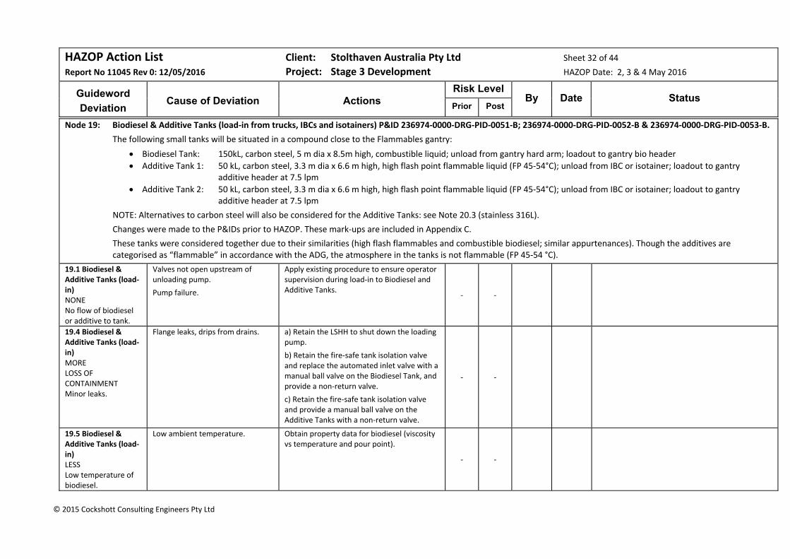
HAZOP Action List Client: Stolthaven Australia Pty Ltd Sheet 32 of 44
Report No 11045 Rev 0: 12/05/2016 Project: Stage 3 Development HAZOP Date: 2, 3 & 4 May 2016
Guideword
Deviation
Cause of Deviation
Actions
Risk Level By Date Status
Prior Post
© 2015 Cockshott Consulting Engineers Pty Ltd
Node 19: Biodiesel & Additive Tanks (load‐in from trucks, IBCs and isotainers) P&ID 236974‐0000‐DRG‐PID‐0051‐B; 236974‐0000‐DRG‐PID‐0052‐B & 236974‐0000‐DRG‐PID‐0053‐B.
The following small tanks will be situated in a compound close to the Flammables gantry:
Biodiesel Tank: 150kL, carbon steel, 5 m dia x 8.5m high, combustible liquid; unload from gantry hard arm; loadout to gantry bio header
Additive Tank 1: 50 kL, carbon steel, 3.3 m dia x 6.6 m high, high flash point flammable liquid (FP 45‐54°C); unload from IBC or isotainer; loadout to gantry additive header at 7.5 lpm
Additive Tank 2: 50 kL, carbon steel, 3.3 m dia x 6.6 m high, high flash point flammable liquid (FP 45‐54°C); unload from IBC or isotainer; loadout to gantry additive header at 7.5 lpm
NOTE: Alternatives to carbon steel will also be considered for the Additive Tanks: see Note 20.3 (stainless 316L).
Changes were made to the P&IDs prior to HAZOP. These mark‐ups are included in Appendix C.
These tanks were considered together due to their similarities (high flash flammables and combustible biodiesel; similar appurtenances). Though the additives are categorised as “flammable” in accordance with the ADG, the atmosphere in the tanks is not flammable (FP 45‐54 °C).
19.1 Biodiesel & Additive Tanks (load‐in) NONE No flow of biodiesel or additive to tank.
Valves not open upstream of unloading pump.
Pump failure.
Apply existing procedure to ensure operator supervision during load‐in to Biodiesel and Additive Tanks.
‐ ‐
19.4 Biodiesel & Additive Tanks (load‐in) MORE LOSS OF CONTAINMENT Minor leaks.
Flange leaks, drips from drains. a) Retain the LSHH to shut down the loading pump.
b) Retain the fire‐safe tank isolation valve and replace the automated inlet valve with a manual ball valve on the Biodiesel Tank, and provide a non‐return valve.
c) Retain the fire‐safe tank isolation valve and provide a manual ball valve on the Additive Tanks with a non‐return valve.
‐ ‐
19.5 Biodiesel & Additive Tanks (load‐in) LESS Low temperature of biodiesel.
Low ambient temperature. Obtain property data for biodiesel (viscosity vs temperature and pour point).
‐ ‐
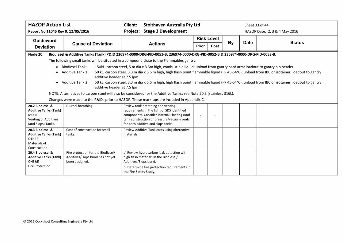
HAZOP Action List Client: Stolthaven Australia Pty Ltd Sheet 33 of 44
Report No 11045 Rev 0: 12/05/2016 Project: Stage 3 Development HAZOP Date: 2, 3 & 4 May 2016
Guideword
Deviation
Cause of Deviation
Actions
Risk Level By Date Status
Prior Post
© 2015 Cockshott Consulting Engineers Pty Ltd
Node 20: Biodiesel & Additive Tanks (Tank) P&ID 236974‐0000‐DRG‐PID‐0051‐B; 236974‐0000‐DRG‐PID‐0052‐B & 236974‐0000‐DRG‐PID‐0053‐B.
The following small tanks will be situated in a compound close to the Flammables gantry:
Biodiesel Tank: 150kL, carbon steel, 5 m dia x 8.5m high, combustible liquid; unload from gantry hard arm; loadout to gantry bio header
Additive Tank 1: 50 kL, carbon steel, 3.3 m dia x 6.6 m high, high flash point flammable liquid (FP 45‐54°C); unload from IBC or isotainer; loadout to gantry additive header at 7.5 lpm
Additive Tank 2: 50 kL, carbon steel, 3.3 m dia x 6.6 m high, high flash point flammable liquid (FP 45‐54°C); unload from IBC or isotainer; loadout to gantry additive header at 7.5 lpm
NOTE: Alternatives to carbon steel will also be considered for the Additive Tanks: see Note 20.3 (stainless 316L).
Changes were made to the P&IDs prior to HAZOP. These mark‐ups are included in Appendix C.
20.2 Biodiesel & Additive Tanks (Tank) MORE Venting of Additives (and Slops) Tanks.
Diurnal breathing. Review tank breathing and venting requirements in the light of SDS identified components. Consider Internal Floating Roof tank construction or pressure/vacuum vents for both additive and slops tanks.
‐ ‐
20.3 Biodiesel & Additive Tanks (Tank) OTHER Materials of Construction
Cost of construction for small tanks.
Review Additive Tank costs using alternative materials.
‐ ‐
20.4 Biodiesel & Additive Tanks (Tank) OHS&E Fire Protection
Fire protection for the Biodiesel/ Additives/Slops bund has not yet been designed.
a) Review hydrocarbon leak detection with high flash materials in the Biodiesel/ Additives/Slops bund.
b) Determine fire protection requirements in the Fire Safety Study.
‐ ‐

HAZOP Action List Client: Stolthaven Australia Pty Ltd Sheet 34 of 44
Report No 11045 Rev 0: 12/05/2016 Project: Stage 3 Development HAZOP Date: 2, 3 & 4 May 2016
Guideword
Deviation
Cause of Deviation
Actions
Risk Level By Date Status
Prior Post
© 2015 Cockshott Consulting Engineers Pty Ltd
Node 21: Biodiesel & Additive Tanks (load‐out) P&ID 236974‐0000‐DRG‐PID‐0051‐B; 236974‐0000‐DRG‐PID‐0052‐B & 236974‐0000‐DRG‐PID‐0053‐B.
The following small tanks will be situated in a compound close to the Flammables gantry:
Biodiesel Tank: 150kL, carbon steel, 5 m dia x 8.5m high, combustible liquid; unload from gantry hard arm; loadout to gantry bio header
Additive Tank 1: 50 kL, carbon steel, 3.3 m dia x 6.6 m high, high flash point flammable liquid (FP 45‐54°C); unload from IBC or isotainer; loadout to gantry additive header at 7.5 lpm
Additive Tank 2: 50 kL, carbon steel, 3.3 m dia x 6.6 m high, high flash point flammable liquid (FP 45‐54°C); unload from IBC or isotainer; loadout to gantry additive header at 7.5 lpm
NOTE: Alternatives to carbon steel will also be considered for the Additive Tanks: see Note 20.3 (stainless 316L).
Changes were made to the P&IDs prior to HAZOP. These mark‐ups are included in Appendix C.
21.1 Biodiesel & Additive Tanks (load‐out) NONE No flow during load‐out.
Valve closed downstream of the loadout pump.
Low level in tank.
Review the pump and thermal relief system for these tanks (internal bypass and thermal relief as per NN7) and ensure suitability with the dosing systems for biodiesel and additives.
‐ ‐
21.2 Biodiesel & Additive Tanks (load‐out) NONE No flow during load‐out.
Valve closed between tank and load‐out pump.
Investigate the type of dosing system to be used for additives and provide no‐flow feedback to stop the delivery pump.
‐ ‐
21.4 Biodiesel & Additive Tanks (load‐out) DIFFERENT Materials of construction.
Attack on elastomers and seals by biodiesel and additives components.
Review elastomers in the biodiesel and additives systems to ensure compatibility with chemical components.
‐ ‐
21.5 Biodiesel & Additive Tanks (load‐out) DIFFERENT
One Additive Tank is to be dedicated to PUMA and the other for Stolthaven use.
Human error in Additive Tank selection
Determine requirements for additive injection to motor spirit products and develop procedural controls to ensure selection of the correct Additive Tank.
‐ ‐
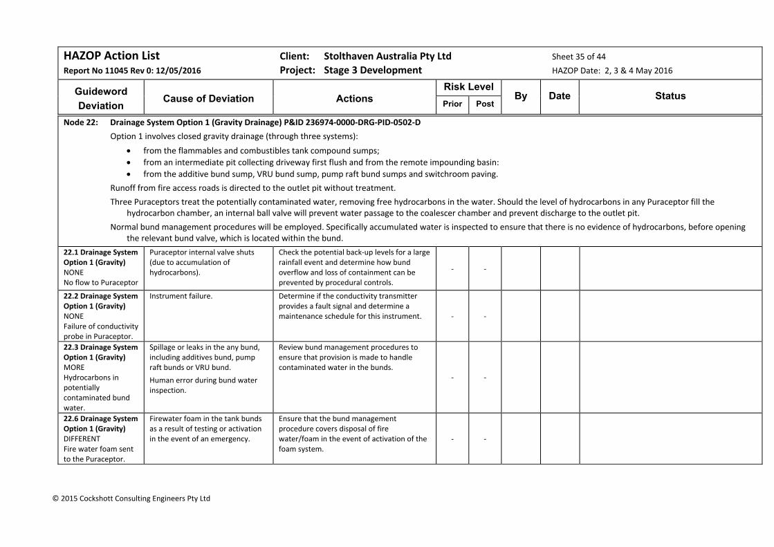
HAZOP Action List Client: Stolthaven Australia Pty Ltd Sheet 35 of 44
Report No 11045 Rev 0: 12/05/2016 Project: Stage 3 Development HAZOP Date: 2, 3 & 4 May 2016
Guideword
Deviation
Cause of Deviation
Actions
Risk Level By Date Status
Prior Post
© 2015 Cockshott Consulting Engineers Pty Ltd
Node 22: Drainage System Option 1 (Gravity Drainage) P&ID 236974‐0000‐DRG‐PID‐0502‐D
Option 1 involves closed gravity drainage (through three systems):
from the flammables and combustibles tank compound sumps;
from an intermediate pit collecting driveway first flush and from the remote impounding basin:
from the additive bund sump, VRU bund sump, pump raft bund sumps and switchroom paving.
Runoff from fire access roads is directed to the outlet pit without treatment.
Three Puraceptors treat the potentially contaminated water, removing free hydrocarbons in the water. Should the level of hydrocarbons in any Puraceptor fill the hydrocarbon chamber, an internal ball valve will prevent water passage to the coalescer chamber and prevent discharge to the outlet pit.
Normal bund management procedures will be employed. Specifically accumulated water is inspected to ensure that there is no evidence of hydrocarbons, before opening the relevant bund valve, which is located within the bund.
22.1 Drainage System Option 1 (Gravity) NONE No flow to Puraceptor
Puraceptor internal valve shuts (due to accumulation of hydrocarbons).
Check the potential back‐up levels for a large rainfall event and determine how bund overflow and loss of containment can be prevented by procedural controls.
‐ ‐
22.2 Drainage System Option 1 (Gravity) NONE Failure of conductivity probe in Puraceptor.
Instrument failure. Determine if the conductivity transmitter provides a fault signal and determine a maintenance schedule for this instrument. ‐ ‐
22.3 Drainage System Option 1 (Gravity) MORE Hydrocarbons in potentially contaminated bund water.
Spillage or leaks in the any bund, including additives bund, pump raft bunds or VRU bund.
Human error during bund water inspection.
Review bund management procedures to ensure that provision is made to handle contaminated water in the bunds.
‐ ‐
22.6 Drainage System Option 1 (Gravity) DIFFERENT Fire water foam sent to the Puraceptor.
Firewater foam in the tank bunds as a result of testing or activation in the event of an emergency.
Ensure that the bund management procedure covers disposal of fire water/foam in the event of activation of the foam system.
‐ ‐
HAZOP Action List Client: Stolthaven Australia Pty Ltd Sheet 36 of 44
Report No 11045 Rev 0: 12/05/2016 Project: Stage 3 Development HAZOP Date: 2, 3 & 4 May 2016
Guideword
Deviation
Cause of Deviation
Actions
Risk Level By Date Status
Prior Post
© 2015 Cockshott Consulting Engineers Pty Ltd
22.8 Drainage System Option 1 (Gravity) OTHER Maintenance.
Inadequate maintenance. Establish an appropriate maintenance regime and procedure for removal and disposal of accumulated hydrocarbons.
‐ ‐
22.11 Drainage System Option 1 (Gravity) OHS&E
Due to site falls, a high rainfall event can result in water depths of up to 0.5m at the bund low point sump in the existing bunds.
Ensure that the bund valves are operable from the bund walls and provide stirs/platforms for access to valve handles and for taking samples.
Residual Risk:
Risk eliminated
Sig (S)
Risk Elim
Node 23: Drainage System Option 2 (Pumpout) P&ID 236974‐0000‐DRG‐PID‐0502‐D
Option 2 involves pumpout (through three closed systems):
from the flammables and combustibles tank compound sumps;
from the driveway first flush pit and from the remote impounding basin:
from the additive bund sump, VRU bund sump, pump raft bund sumps and switchroom paving.
Runoff from fire access roads is directed to the outlet pit without treatment.
Three Puraceptors treat the potentially contaminated water, removing free hydrocarbons in the water. Should the level of hydrocarbons in any Puraceptor fill the hydrocarbon chamber, an internal ball valve will prevent water passage to the coalescer chamber and prevent discharge to the outlet pit.
Normal bund management procedures will be employed. Specifically accumulated water is inspected to ensure that there is no evidence of hydrocarbons, before pumping out the relevant bund. The bund pump will be located on the bund wall.
23.2 Drainage System Option 2 (Pumpout) NONE Failure of conductivity probe in Puraceptor.
Instrument failure. Determine if the conductivity transmitter provides a fault signal and determine a maintenance schedule for this instrument. ‐ ‐
23.3 Drainage System Option 2 (Pumpout) MORE Hydrocarbons in potentially contaminated bund water.
Spillage or leaks in the any bund, including additives bund, pump raft bunds or VRU bund.
Human error during bund water inspection.
Review bund management procedures to ensure that provision is made to handle contaminated water in the bunds.
‐ ‐

HAZOP Action List Client: Stolthaven Australia Pty Ltd Sheet 37 of 44
Report No 11045 Rev 0: 12/05/2016 Project: Stage 3 Development HAZOP Date: 2, 3 & 4 May 2016
Guideword
Deviation
Cause of Deviation
Actions
Risk Level By Date Status
Prior Post
© 2015 Cockshott Consulting Engineers Pty Ltd
23.4 Drainage System Option 2 (Pumpout) MORE High pressure to the Puraceptor
Too many pumpout pumps operating simultaneously.
a) Ensure that the pumpout pumps’ design outlet pressures are sufficiently low so as not to overpressurise the closed drainage system and the capacities such that the system will not be overloaded.
b) Determine if an orifice plate provides any useful function for the pumpout option.
c) Determine if the Puraceptor vent stack (overflow) can be directed to the nearest bund.
‐ ‐
23.5 Drainage System Option 2 (Pumpout) DIFFERENT Emulsion fed to Puraceptor.
Emulsification by the bund pumpout pump of contaminated water.
Ensure that bund pumpout pumps are not high shear.
‐ ‐
23.6 Drainage System Option 2 (Pumpout) DIFFERENT Fire water foam sent to the Puraceptor.
Firewater foam in the tank bunds as a result of testing or activation in the event of an emergency.
Ensure that the bund management procedure covers disposal of fire water/foam in the event of activation of the foam system.
‐ ‐
23.8 Drainage System Option 2 (Pumpout) OTHER Maintenance.
Inadequate maintenance. Establish an appropriate maintenance regime and procedure for removal and disposal of accumulated hydrocarbons.
‐ ‐

HAZOP Action List Client: Stolthaven Australia Pty Ltd Sheet 38 of 44
Report No 11045 Rev 0: 12/05/2016 Project: Stage 3 Development HAZOP Date: 2, 3 & 4 May 2016
Guideword
Deviation
Cause of Deviation
Actions
Risk Level By Date Status
Prior Post
© 2015 Cockshott Consulting Engineers Pty Ltd
23.9 Drainage System Option 2 (Pumpout) OTHER Reduce complexity
Reduce the number of Puraceptors.
Review the option of providing a single large Puraceptor. This would potentially have the following advantages:
Potentially lower purchase and installation cost compared with three units;
Only one outfall to the creek need be installed;
All piping can run above ground with savings in installation cost and maintenance;
Cut and fill minimised;
Simplification of maintenance activities.
‐ ‐
23.10 Drainage System Option 2 (Pumpout) OTHER ESD Action
Bund pumps are operated manually on/off buttons with low sump level automated stop (float valve).
Review provision of a single header for motive air supply for all bund pumps and provision of an ESD‐activated shutoff valve on the air supply.
‐ ‐
23.11 Drainage System Option 2 (Pumpout) OHS&E
Due to site falls, a high rainfall event can result in water depths of up to 0.5m at the bund low point sump in the existing bunds.
Ensure that the bund sump pumps are mounted on the bund walls with stairs/platforms for safe access to the on/off buttons and for taking samples.
‐ ‐
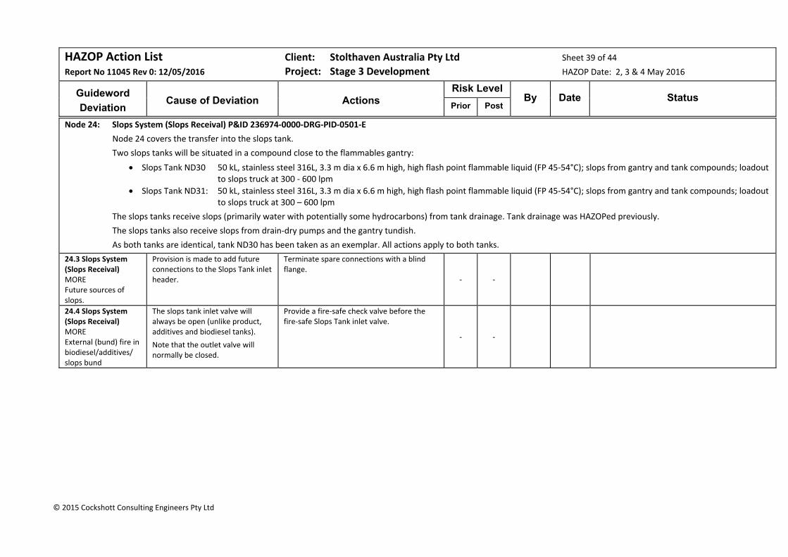
HAZOP Action List Client: Stolthaven Australia Pty Ltd Sheet 39 of 44
Report No 11045 Rev 0: 12/05/2016 Project: Stage 3 Development HAZOP Date: 2, 3 & 4 May 2016
Guideword
Deviation
Cause of Deviation
Actions
Risk Level By Date Status
Prior Post
© 2015 Cockshott Consulting Engineers Pty Ltd
Node 24: Slops System (Slops Receival) P&ID 236974‐0000‐DRG‐PID‐0501‐E
Node 24 covers the transfer into the slops tank.
Two slops tanks will be situated in a compound close to the flammables gantry:
Slops Tank ND30 50 kL, stainless steel 316L, 3.3 m dia x 6.6 m high, high flash point flammable liquid (FP 45‐54°C); slops from gantry and tank compounds; loadout to slops truck at 300 ‐ 600 lpm
Slops Tank ND31: 50 kL, stainless steel 316L, 3.3 m dia x 6.6 m high, high flash point flammable liquid (FP 45‐54°C); slops from gantry and tank compounds; loadout to slops truck at 300 – 600 lpm
The slops tanks receive slops (primarily water with potentially some hydrocarbons) from tank drainage. Tank drainage was HAZOPed previously.
The slops tanks also receive slops from drain‐dry pumps and the gantry tundish.
As both tanks are identical, tank ND30 has been taken as an exemplar. All actions apply to both tanks.
24.3 Slops System (Slops Receival) MORE Future sources of slops.
Provision is made to add future connections to the Slops Tank inlet header.
Terminate spare connections with a blind flange.
‐ ‐
24.4 Slops System (Slops Receival) MORE External (bund) fire in biodiesel/additives/ slops bund
The slops tank inlet valve will always be open (unlike product, additives and biodiesel tanks).
Note that the outlet valve will normally be closed.
Provide a fire‐safe check valve before the fire‐safe Slops Tank inlet valve.
‐ ‐

HAZOP Action List Client: Stolthaven Australia Pty Ltd Sheet 40 of 44
Report No 11045 Rev 0: 12/05/2016 Project: Stage 3 Development HAZOP Date: 2, 3 & 4 May 2016
Guideword
Deviation
Cause of Deviation
Actions
Risk Level By Date Status
Prior Post
© 2015 Cockshott Consulting Engineers Pty Ltd
24.5 Slops System (Slops Receival) MORE High level in slops tank.
The terminal may be unmanned. Slops will continually be added from the gantries.
a) Provide a LAH interlocked to an automated Slops Tank inlet valve.
b) Provide a separate LSHH interlocked to the site ESD.
c) Provide an air supply system for the dewatering, bund drainage and gantry slops pumps (See Action 23.10 for bund pumps) which will be isolated in the event of a site ESD.
d) Ensure that Slops Tank LAH‐inlet valve SIF and LSHH‐motive air SIF are included in the SIL/SFARP Study.
Residual Risk:
Assuming both LAH‐inlet valve SIF is SIL2 and LSHH‐motive air SIF is SIL2, then the likelihood is:
1/10/yr x /100 x 1/100 = 100,000 /yr
B Cred x Cat = Low Risk (S)
High (S)
Low (S)
24.6 Slops System (Slops Receival) LESS Inadequate Slops Tank inlet manifold size.
The size of manifold is 50mm. Check header for 9 slops pumps operating 7 small pumps plus 2 large ones. Velocity should preferably be kept to 1 m/s for two phase hydrocarbon/water flow.
Residual Risk:
N Cred x Cat = Low Risk (S)
Sig (S)
Low (S)
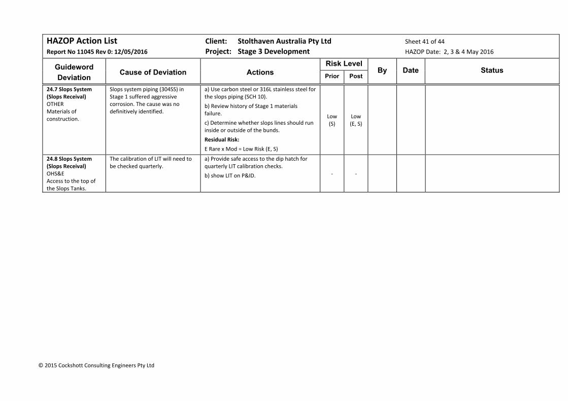
HAZOP Action List Client: Stolthaven Australia Pty Ltd Sheet 41 of 44
Report No 11045 Rev 0: 12/05/2016 Project: Stage 3 Development HAZOP Date: 2, 3 & 4 May 2016
Guideword
Deviation
Cause of Deviation
Actions
Risk Level By Date Status
Prior Post
© 2015 Cockshott Consulting Engineers Pty Ltd
24.7 Slops System (Slops Receival) OTHER Materials of construction.
Slops system piping (304SS) in Stage 1 suffered aggressive corrosion. The cause was no definitively identified.
a) Use carbon steel or 316L stainless steel for the slops piping (SCH 10).
b) Review history of Stage 1 materials failure.
c) Determine whether slops lines should run inside or outside of the bunds.
Residual Risk:
E Rare x Mod = Low Risk (E, S)
Low (S)
Low (E, S)
24.8 Slops System (Slops Receival) OHS&E Access to the top of the Slops Tanks.
The calibration of LIT will need to be checked quarterly.
a) Provide safe access to the dip hatch for quarterly LIT calibration checks.
b) show LIT on P&ID. ‐ ‐

HAZOP Action List Client: Stolthaven Australia Pty Ltd Sheet 42 of 44
Report No 11045 Rev 0: 12/05/2016 Project: Stage 3 Development HAZOP Date: 2, 3 & 4 May 2016
Guideword
Deviation
Cause of Deviation
Actions
Risk Level By Date Status
Prior Post
© 2015 Cockshott Consulting Engineers Pty Ltd
Node 25: Slops System (Slops Disposal) P&ID 236974‐0000‐DRG‐PID‐0501‐E
Node 25 covers disposal of slops to the slops truck at the gantry.
Two slops tanks will be situated in a compound close to the flammables gantry:
Slops Tank ND30 50 kL, stainless steel 316L, 3.3 m dia x 6.6 m high, high flash point flammable liquid (FP 45‐54°C); slops from gantry and tank compounds; loadout to slops truck at 300 ‐ 600 lpm
Slops Tank ND31: 50 kL, stainless steel 316L, 3.3 m dia x 6.6 m high, high flash point flammable liquid (FP 45‐54°C); slops from gantry and tank compounds; loadout to slops truck at 300 – 600 lpm
Load‐out will be accomplished using the slops tank on‐board pump.
As both tanks are identical, tank ND30 has been taken as an exemplar. All actions for ND30 apply to ND31.
25.1 Slops System (Slops Disposal) NONE No vapour return.
No provision is made for vapour return from the truck.
a) Review with slops disposal company:
Provision of vapour recovery piping with the connection at ground level;
The capacity of the vacuum pump on the truck.
Overfill protection arrangements;
Earthing provisions. b) Design a vapour recovery system (similar to that provided for product tankers) for the slops tanker.
c) Determine if metering of slops is required for safe filling.
Assuming vapour recovery can be implemented,
Residual Risk:
Risk eliminated
Sig (S)
Risk Elim
25.2 Slops System (Slops Disposal) NONE No flow to slops tank
Valve closed at slops tank. Ensure that the delivery hose is designed to take full vacuum.
Residual Risk:
Risk eliminated
Mod (S)
Risk Elim

HAZOP Action List Client: Stolthaven Australia Pty Ltd Sheet 43 of 44
Report No 11045 Rev 0: 12/05/2016 Project: Stage 3 Development HAZOP Date: 2, 3 & 4 May 2016
Guideword
Deviation
Cause of Deviation
Actions
Risk Level By Date Status
Prior Post
© 2015 Cockshott Consulting Engineers Pty Ltd
25.3 Slops System (Slops Disposal) NONE No flow to slops tank.
Slops truck on‐board pump unserviceable.
Provide a 50mm stub and blanked valve at a low point on the delivery line as a low point drain and for connection of a temporary transfer pump.
‐ ‐
25.4 Slops System (Slops Disposal) MORE LOSS OF CONTAINMENT
Open drain connection or transfer hose not connected.
a) Develop a procedure for slops disposal. Ensure that the operation is supervised by an operator.
b) Provide a ball valve at the fire‐safe slops tank isolation valve.
Residual Risk:
Unlikely x Min = Low Risk (S)
Mod (S)
Risk Elim
25.5 Slops System (Slops Disposal) MORE High velocity in transfer line to slops tanker.
Pump capacity too high. a) Review slops tanker on‐board pump capacity and ensure that the line velocity does not result in the potential for static generation (two phase hydrocarbon/water flow).
b) Ensure provision is made for tanker earthing and electrical continuity. Ensure that earthing is included in the procedure.
c) If tank dipping is required, specify a minimum relaxation time in the procedure.
‐ ‐
25.6 Slops System (Slops Disposal) LESS Low flow to slops tanker.
Slow slops tanker loading rate. Aim for slops loading rate of 300 lpm (18 kL per hour). As a balance between loading time and static generation. ‐ ‐
25.7 Slops System (Slops Disposal) LESS Low level in slops tank.
Slops tank emptied during slops transfer.
Determine the minimum level that should remain in the slops tank after disposal and include how this should be controlled in the procedure. (Is the LAL required as a safeguard in addition to monitoring level?)
‐ ‐
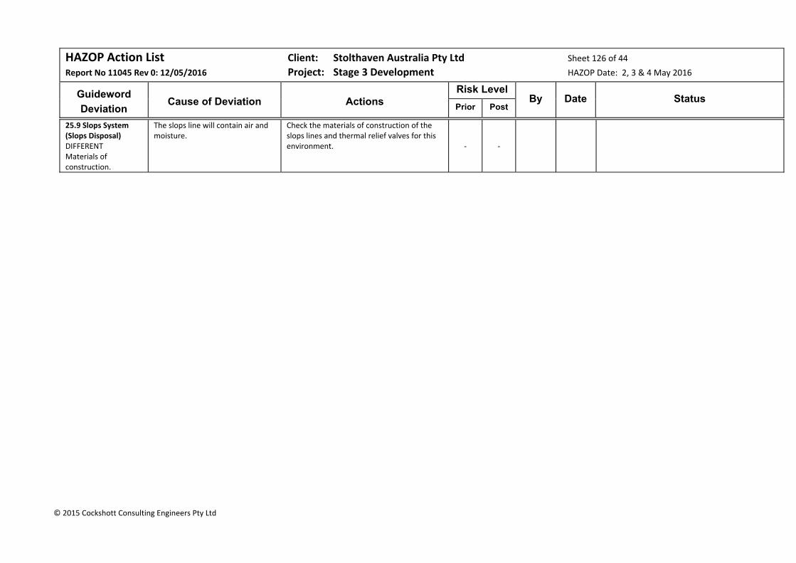
HAZOP Action List Client: Stolthaven Australia Pty Ltd Sheet 126 of 44
Report No 11045 Rev 0: 12/05/2016 Project: Stage 3 Development HAZOP Date: 2, 3 & 4 May 2016
Guideword
Deviation
Cause of Deviation
Actions
Risk Level By Date Status
Prior Post
© 2015 Cockshott Consulting Engineers Pty Ltd
25.9 Slops System (Slops Disposal) DIFFERENT Materials of construction.
The slops line will contain air and moisture.
Check the materials of construction of the slops lines and thermal relief valves for this environment. ‐ ‐
Cockshott Consulting Engineers 125 Report 11045 Rev 1A for comment: 17 May 2016
8 Model Parameters
Three inputs factors are important in modelling pool fires: the burning rate, the fraction of heat radiated and the soot fraction. Recent data (ca. 2000) has become available for experiments conducted on large pool fires, in the range of the Mayfield tank diameters – in particular, NRIFD5 and NISTIR 65466.Much of the experimental data prior to 2000 was based on relatively small pool fires (~1m diameter and less). The pool burning rate was taken from the following references:
NRIFD7 (Figure 1)
NRIFD (Figure 11)
NISTIR 65468 (Table 1)
The fraction of heat radiated for diesel fuel was taken from:
NISTIR 6546 (Figure 3)
NRIFD (Figure 2)
The soot fraction was taken from the TNO Yellow Book9. Table 12 summarises the burning rates derived from various sources. At large pool diameters (>5m), the burning rate for hydrocarbon products is virtually independent of both diameter and product in terms of linear burning rate (mm/min). The differences in Table 12 reflect the SG of the product. The values by NISTR6546 and the Yellow Book are tabulated values for large pool fires.
Table 12 Values of Burning Rate (kg/m3/s)
AGO Petrol Jet Fuel Ethanol
NRIFD (Fig 1) 0.049 0.043 0.047 ‐
NRIFD (Fig 11) 0.056 0.050 0.053 ‐
NISTR 6546 ‐ 0.055 0.054 0.015
Yellow Book ‐ 0.055 0.054 0.015
Value used 0.06 0.06 0.06 0.02 Values for Radiative Fraction from NIST & NRFID are provided in Table 13 and are independent of product and highly dependent on pool diameter.
Table 13 Values of Radiative Fraction (NIST & NRIFD)
Pool Diameter (m)
7.5 15 25 30 38
NIST 0.24 0.14 0.08 0.07 0.06
NRIFD 0.25 0.12 0.11 0.06 0.045
Value used 0.30 0.16 0.14 0.12 0.10 The TNO Yellow Book recommends a soot fraction of 0.8 as “the representative figure (in literature) for pool fires of oil products”. There are no recent data which update previous assumptions of soot fraction (See Steinhaus10). Steinhaus confirms the value of 80%. This value is likely to be conservative for large pool fires, as soot level increases for large fires which have a lower luminous layer and an upper optically
5 Large Scale Pool Fires: Results of Recent Experiments Hiroshi Koseki, National Research Institute of Fire & Danger, Fire Safety Science – Proceedings of the Sixth International Symposium pp 115‐132 6 Thermal Radiation from Large Pool Fires, K McGrattan et al, National Institute of Standards & Technology, Technology Administration, US Department of Commerce, NISTIR 6546 7 Large Scale Pool Fires: Results of Recent Experiments, Hiroshi Koseki, National Research Institute of Fire & Danger, Fire Safety Science – Proceedings of the Sixth International Symposium pp 115‐132 8 Thermal Radiation from Large Pool Fires, K McGrattan et al, National Institute of Standards & Technology, Technology Administration, US Department of Commerce, NISTIR 6546 9 Methods for the Calculation of Physical Effects (Part 2) CPR 14E (the “Yellow Book”), Committee for Prevention of Disasters, TNO – The Netherlands Organisation of Applied Scientific Research 10 Large Scale pool Fires, Steinhaus et al, BRE Review paper UDC: 536.24/.25:614.841.41 BIBLID: 0354‐9836, 11 (2007),2, pp. 101‐118

Cockshott Consulting Engineers 126 Report 11045 Rev 1A for comment: 17 May 2016
opaque layer (Steinhaus). Steinhaus also points out that alcohol pool fires burn very cleanly, producing little soot. Therefore, a soot fraction of 0.8 has been assumed for AGO, petrol and jet fuel, and 0.1 has been assumed for ethanol.
Cockshott Consulting Engineers 127 Report 11045 Rev 1A for comment: 17 May 2016
9 Consequence Analysis
This section provides the results of consequence analysis performed both for external adverse scenarios which may impact on the Stolthaven Newcastle Terminal and events which may be initiated by terminal operations.
9.1 Ammonium Nitrate Explosion
Ammonium nitrate (AN) will not be stored at the M7 berth. However, AN is manufactured and stored at the Orica Australia Pty Ltd plant on Kooragang Island at the entrance to the Mayfield arm of the port. Current production of the AN facility is 500 ktpa and a proposal will increase this to 750 ktpa11.
A preliminary Hazard Analysis was conducted for Orica Mining Services for a proposed expansion increase in quantities in May 200912. This PHA presented overpressure injury contours (7 kPa) of 50 x 10‐6 per annum (entirely within the new project boundary) and overpressure fatality contours (14 kPa) of 50 x 10‐6 per annum which extended into the neighbouring industrial facilities zoned for potentially hazardous development).
These reports relate to the expansion project only and not the current AN manufacturing operation. The risk contours are also insufficient to determine possible impacts to operations on M7 berth operations.
It was therefore necessary to model potential ammonium nitrate explosions at the K2 berth and the Orica manufacturing facility to determine potential explosion overpressure effects at M7. The TNO13 Effects 9.0.22 Equivalent TNT model was used for explosion modelling. Neither of the reports quoted above indicate the quantity of AN used in the consultant’s explosion risk assessment. For the purpose of determining potential effects at M7, it was assumed that a cargo vessel carrying 3,000 tonnes or a storage of 5,000 tonnes at the manufacturing facility is involved in an explosion. The basis for these assumptions comes from Orica statements regarding marine vessel warehousing of ammonium nitrate14 and the on‐site storage quantity of 15,500 tonnes of bulk and 2,500 tonnes of bagged product reported in the Preliminary Hazard Analysis2.
In developing these worst case scenarios, a measure of the equivalent explosive power to TNT is used. For the Orica Preliminary Hazard Analysis2 above, the overall TNT Equivalency Values used for explosion overpressures were 20% for bags, 15% for bulk in bays and 10% for bulk in free stockpiles; 32% was used for projectile estimation.
Other sources use higher values:
The Council of Australian Governments (COAG) Ammonium Nitrate Guidance Note No 4 uses a TNT Equivalency Value of 32% for loosely stacked ammonium nitrate in determining separation distances.
The Western Australia Department of Mines and Petroleum takes the TNT equivalence as 25%, sourced from “Safety Testing of Ammonium Nitrate Products”15.
The Queensland Government has adopted a TNT equivalence of 32%16.
The explosion overpressure contours for this risk assessment have been developed using a TNT equivalence of 32%, representing the most conservative view adopted by Australian Governments.
11 Environmental Assessment Scoping Report: Planning Approval for Uprating of Ammonium Nitrate Facility Kooragang Island. ENSR Australia 20 June 2008
12 Report for Kooragang Island Facility Uprate – Preliminary Hazard Analysis May 2009
13 TNO – The Netherlands Organisation of Applied Scientific Research
14 Newcastle Herald Report, 30 April 2013
15 Proceedings No 580 ‐ Safety Testing of Ammonium Nitrate Products, International Fertiliser Society 2006
16 Information Bulletin No 53 (Version 33) Storage Requirements for Security‐Sensitive Ammonium Nitrate (SSAN), Explosives Inspectorate 2008
Cockshott Consulting Engineers 128 Report 11045 Rev 1A for comment: 17 May 2016
The overpressure contours resulting from an explosion of a cargo of 3,000 tonnes of ammonium nitrate centred at K2 berth are shown in Figure 4. A similar plot is provided for an explosion of 5,000 tonnes of AN at the manufacturing facility (Figure 5).
Figure 4 Explosion Effects: 3,000 Tonne Ammonium Nitrate Cargo (K2)
Figure 5 Explosion Effects 5,000 tonnes AN Storage (Kooragang Is)
Overpressure Contours: Yellow: Minor damage Blue: 7 kPa Orange: Moderate damage Mauve: Heavy damage Red: Total destruction
OverpressureContours: Blue: 7 kPa Orange: Moderate damage Mauve: Heavy damage Red: Total destruction
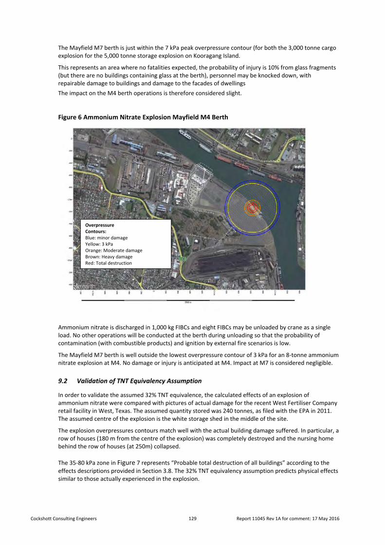
Cockshott Consulting Engineers 129 Report 11045 Rev 1A for comment: 17 May 2016
The Mayfield M7 berth is just within the 7 kPa peak overpressure contour (for both the 3,000 tonne cargo explosion for the 5,000 tonne storage explosion on Kooragang Island.
This represents an area where no fatalities expected, the probability of injury is 10% from glass fragments (but there are no buildings containing glass at the berth), personnel may be knocked down, with repairable damage to buildings and damage to the facades of dwellings
The impact on the M4 berth operations is therefore considered slight.
Figure 6 Ammonium Nitrate Explosion Mayfield M4 Berth
Ammonium nitrate is discharged in 1,000 kg FIBCs and eight FIBCs may be unloaded by crane as a single load. No other operations will be conducted at the berth during unloading so that the probability of contamination (with combustible products) and ignition by external fire scenarios is low.
The Mayfield M7 berth is well outside the lowest overpressure contour of 3 kPa for an 8‐tonne ammonium nitrate explosion at M4. No damage or injury is anticipated at M4. Impact at M7 is considered negligible.
9.2 Validation of TNT Equivalency Assumption
In order to validate the assumed 32% TNT equivalence, the calculated effects of an explosion of ammonium nitrate were compared with pictures of actual damage for the recent West Fertiliser Company retail facility in West, Texas. The assumed quantity stored was 240 tonnes, as filed with the EPA in 2011. The assumed centre of the explosion is the white storage shed in the middle of the site.
The explosion overpressures contours match well with the actual building damage suffered. In particular, a row of houses (180 m from the centre of the explosion) was completely destroyed and the nursing home behind the row of houses (at 250m) collapsed.
The 35‐80 kPa zone in Figure 7 represents “Probable total destruction of all buildings” according to the effects descriptions provided in Section 3.8. The 32% TNT equivalency assumption predicts physical effects similar to those actually experienced in the explosion.
OverpressureContours: Blue: minor damage Yellow: 3 kPa Orange: Moderate damage Brown: Heavy damage Red: Total destruction

Cockshott Consulting Engineers 130 Report 11045 Rev 1A for comment: 17 May 2016
Figure 7 West, Texas, Fertiliser Retail Facility Explosion
Figure 8 Damage Caused by Fertiliser Retail Facility Explosion (View 1)
OverpressureContours: Orange: 17 kPa Brown: 35 kPa Red: 80 kPa
Nursing Home collapsed
Home s completely destroyed
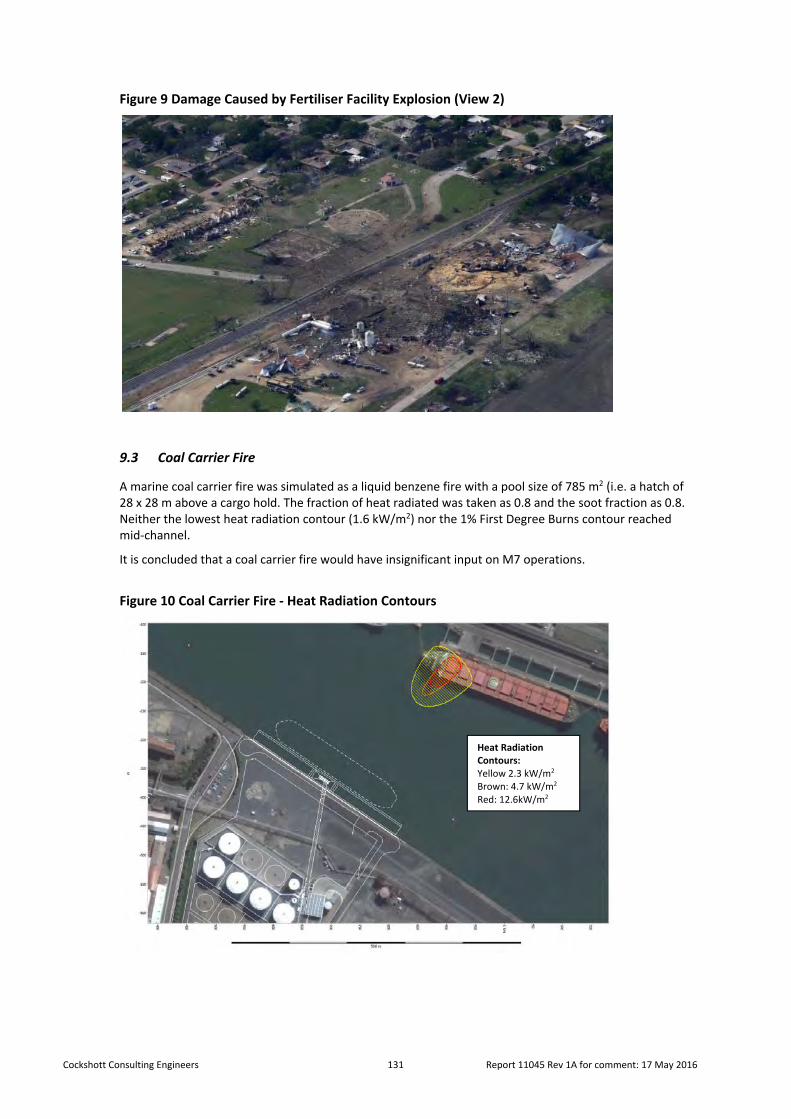
Cockshott Consulting Engineers 131 Report 11045 Rev 1A for comment: 17 May 2016
Figure 9 Damage Caused by Fertiliser Facility Explosion (View 2)
9.3 Coal Carrier Fire
A marine coal carrier fire was simulated as a liquid benzene fire with a pool size of 785 m2 (i.e. a hatch of 28 x 28 m above a cargo hold. The fraction of heat radiated was taken as 0.8 and the soot fraction as 0.8. Neither the lowest heat radiation contour (1.6 kW/m2) nor the 1% First Degree Burns contour reached mid‐channel.
It is concluded that a coal carrier fire would have insignificant input on M7 operations.
Figure 10 Coal Carrier Fire ‐ Heat Radiation Contours
Heat RadiationContours: Yellow 2.3 kW/m2 Brown: 4.7 kW/m2 Red: 12.6kW/m2

Cockshott Consulting Engineers 132 Report 11045 Rev 1A for comment: 17 May 2016
Figure 11 Coal Carrier Fire ‐ Affects to Personnel
9.4 Wharf Fires
Figure 12 shows the extent of heat radiation contours for a petrol pool fire at the bunded working area at the berth. A berth fire will not result in an impact on the terminal storage tanks.
Figure 12 Petrol Fire at Berth M7
Contour: 1% First Degree Burns
Heat Radiation Contours: Yellow 4.7 kW/m2 Brown: 12.6 kW/m2 Red: 23 kW/m2

Cockshott Consulting Engineers 133 Report 11045 Rev 1A for comment: 17 May 2016
9.5 Wharf Spill Resulting in a Flash Fire
The ignition of a flammable cloud from a major petrol spill at the wharf was simulated using n‐pentane as a representative pure chemical. A concentration of 1.3% (100% of LEL) was used to estimate the extent of a flammable vapour cloud resulting from a major gasoline spill at the wharf. Under the most adverse conditions (atmospheric Stability Class F), a flammable cloud will be within to the site boundary shoreside but is calculated to extend into the channel (shown by the LEL footprints for eight wind directions in Figure 13). In practice, the flammable vapour cloud will be disrupted by the presence of the berthed vessel and the extent of a flammable cloud of overwater will be reduced from that depicted.
For Stability Class A, the footprint is much smaller (shown by the blue contour line in Figure 13). No LEL contour is predicted for other stability classes.
Figure 13 Extent of Flammable Cloud from a Wharf Petrol Spill
For an ethanol spill, a flammable cloud is not predicted beyond the wharf working (spill containment) area.
For Jet Fuel and Diesel, no flammable cloud results from a wharf spill.
9.6 Terminal Tank Fires
The flammables storage tanks are located on Lot 36, the central portion of the site to be developed for Stage 3.
Figure 14 depicts the impact of tank top fires for flammable liquids tanks located on Lot 36. The 4.7 kW/m2 footprints are shown for selected wind directions to provide an appreciation of impacts outside of the bunds.
Contour:Extent & Footprint of Flash Fire
Cockshott Consulting Engineers 134 Report 11045 Rev 1A for comment: 17 May 2016
Figure 14 Tank Top Fires, Flammable Tanks, Lot 36 (4.7 kW/m2 at 1.5m receptor)
It can be seen that for tanks on the western part of Lot 36, and with a wind from an easterly direction, the 1.5m 4.7 kW/m2 heat radiation impact of tank top fires on personnel extends as far as the line of trees to the west of Lot 36 but not as far as the railway line or the roadway.
9.7 Tank Loss of Containment
In the event of loss of containment from a petrol or ethanol storage tank, a flammable liquid pool will formed in the bund and this will evaporate to create a flammable cloud. The surface area of the pool, which determines the total evaporation rate, will depend on the volume of the spill.
Within the main bunds, low compound walls provide for containment of moderate spills within the smaller compound bunding. For moderate spills (e.g. up to about 10‐15 minutes overfilling during marine discharge) the liquid pool will be contained within the associated compound bund.
For large spills (e.g. total tank failure) the entire bund (consisting of several compounds) will be filled.
9.7.1 Tank Loss of Containment (Moderate)
In the case of a moderate sized spill (one that is contained in the compound bund) the evaporation rate will be limited to the net area of the tank’s compound.
Figure 15 shows a typical moderate loss of containment scenario (for Tank ND13, petrol) representing the boundary of a flammable vapour cloud at 1.5m for a contained compound petrol spill, for Class F Stability atmospheric conditions and easterly wind. A flammable vapour cloud outside the compound bund is not predicted for other meteorological conditions.
In the event of ignition, a flash fire will occur back to the pool and a fatality will occur to any people within the within the LEL footprint.
Heat RadiationContours: Brown 4.7 kW/m2
Cockshott Consulting Engineers 135 Report 11045 Rev 1A for comment: 17 May 2016
Figure 15 Petrol Spill contained in Compound – Tank ND13
Figure 16 shows the heat radiation curves (4.7 kW/m2) for a compound bund fire (ND13) for an easterly wind.
Figure 16 Compound Bund Fires
Heat RadiationContours: Green: 4.7 kW/m2 Brown: 12.6 kW/m2 Red: 23 kW/m2
Cockshott Consulting Engineers 136 Report 11045 Rev 1A for comment: 17 May 2016
9.7.2 Tank Loss of Containment (Large)
In the event of a large loss of containment (a major tank rupture or extended overfill event), a spill will not be contained within the tank compound walls but will cover the entire bund. For instance, if the entire contents of tank CD13 were released, the evaporating pool would cover the full CD13/14/15/16/25/26 bund (the “Mid” bund). The larger liquid surface area (compared with a compound spill) results in flammable cloud of significant dimensions under Stability F wind conditions, which comprise 15% of all observations.
The brown outline of Figure 17 represents the extent of the flammable vapour cloud for an easterly wind under F1.9 conditions (Stability Class F, 1.8 m/s). In the case of ignition, a flash fire (or VCE) will occur. For the case of flash fire, the contour represents an area of 100% chance of fatality for all people exposed outside buildings.
A necessary requirement for a vapour cloud explosion is that the flammable gas cloud must be confined. This means that closely spaced equipment, building or trees need to be present so that the deflagration associated with a flash fire develops into a detonation.
The circular contours represent the extent of explosion overpressure events resulting from ignition of the flammable vapour cloud.
Legend for explosion overpressure contours:
7 kPa No fatalities; 10% chance of minor injury;
Repairable building damage.
14 kPa No fatalities; 20% chance of moderate injury;
Failure to block walls & self‐framing panel buildings;
Serious damage to steel‐framed buildings.
21 kPa 20% chance of fatalities (persons within buildings); 2% chance of serious injury (eardrums & flying objects);
Heavy damage to buildings and process equipment;
Failure of oil storage tanks.
Figure 17 Full Bund Spill ‐ Mid Bund Petrol Spill & VCE

Cockshott Consulting Engineers 137 Report 11045 Rev 1A for comment: 17 May 2016
The extent of the flash fire resulting from a large bund spill will also depend on the time before ignition. Figure 18 shows the development of a full bund spill 3 minutes after the spill is fully developed. The brown and red areas show the extent of the flammable cloud at that time.
The heat radiation contours for a full bund fire are shown for CD13 in Figure 19.
Figure 18 Flammable concentration at 180s
Figure 19 Full Bund Fire ‐ Lot 36 ‐ Mid Bund
Heat RadiationContours: Green: 4.7 kW/m2 Brown: 12.6 kW/m2 Red: 23 kW/m2

Cockshott Consulting Engineers 138 Report 11045 Rev 1A for comment: 17 May 2016
10 Frequency Analysis
10.1 MLA Failure Rates
Recent Hazard Analyses for ports in NSW have considered the frequency of marine loading arm failures. For the preliminary hazard analysis17 for the Port Botany Bulk Liquids Berth No 2 (by others), the failure frequency was estimated by considering the MLA as a 300mm pipeline of 300 mm diameter and a length of approximately 30m.
Applying the failure frequency of 5.8 x 10‐8 pa to this length of pipe resulted in an MLA failure frequency of 1.7 x 10‐6 pa. Assuming that each MLA is used 100 times a year, this equates to a failure rate of 1.7 x 10‐8 per operation. This failure rate is much lower than that reported in the literature.
We have reviewed authoritative sources and these report similar orders of magnitude.
Table 14 presents the frequencies for oil release related to loading of product tankers from marine loading arms, from a study performed by DNV for the UK HSE in 1990.
Table 14 Frequency of Release from Marine Loading Arms (DNV)
No
Failure mode
Frequency per loading
operation
Release size distribution
small medium large
A Release from loading arm 5.1 x 10‐5 0.8 0.19 0.01
B Loading arm quick connection release 5.1 x 10‐6 0 0 1
C Failure in vessel piping or pumping system 7.2 x 10‐6 0.8 0.19 0.01
D Human failure 7.2 x 10‐6 0.8 0.19 0.01
E Mooring failure 3.8 x 10‐6 0 0 1
F Overfilling of cargo tank 1.2 x 10‐4 0.8 0.19 0.01
Total 1.9 x 10‐4
The shutdown times are assumed to be 2 minutes for a major leak (0‐60 sec for detection and 0‐60 sec for shutdown).
Table 15 presents the TNO Purple Book data. No duration information is provided.
Table 15 Frequency of Release from Marine Loading Arms (TNO)
Full bore loading arm failure Leak of unloading arm
(10% of loading arm with a maximum of 10% of the arm diameter)
Failure per transhipment 6 x 10‐5 6 x 10‐4
The UK HSE published failure rates for marine loading arms18 in 2012 and presents two tables (reproduced
here as Table 16 & Table 17). The tables are for liquefied gases and liquid cargoes respectively. The significant difference between the two tables is that liquefied gas unloading arms are assumed to have emergency release couplings (ERC) designed to achieve a quick release with minimum of spillage.
17 The Bulk Liquids Berth No 2 – Port Botany Preliminary Hazard Analysis, Sinclair Knight Merz, 12 Nov 2007
18 UK HSE Failure Rate and Event Data for use within Risk Assessment (28 June 2012)

Cockshott Consulting Engineers 139 Report 11045 Rev 1A for comment: 17 May 2016
Table 16 Frequency of Release from Marine Loading Arms (UK HSE): Liquefied Gas (No ERC fitted)
Failure frequencies per transfer operation for liquid cargo
Cause of failure Guillotine break Hole 10% of cross sectional area
Simultaneous guillotine breaks (for multiple arms)
Connection failures
Arm 3.4 x 10‐7 3.1 x 10‐6
Coupler 5.1 x 10‐6 ‐
Operator error 5.4 x 10‐7 4.9 x 10‐6
Sub‐total per arm 6.0 x 10‐6 8.0 x 10‐5
Ranging failures Assumed that ranging alarms are provided on the MLA
Mooring fault 6.0 x 10‐7
Passing ships 2.0 x 10‐7
Subtotal per system 0.8 x 10‐6 3.2 x 10‐6
Where multiple hard arms are used
Total failures when one arm used 7.0 x 10‐6 8.0 x 10‐6
Total failures when 2 arms used 13.0 x 10‐6 16.0 x 10‐6 1.0 x 10‐7
Total failures when 3 arms used 19.0 x 10‐6 24.0 x 10‐6 1.0x 10‐7
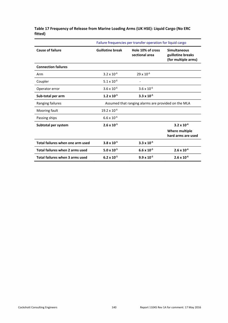
Cockshott Consulting Engineers 140 Report 11045 Rev 1A for comment: 17 May 2016
Table 17 Frequency of Release from Marine Loading Arms (UK HSE): Liquid Cargo (No ERC fitted)
Failure frequencies per transfer operation for liquid cargo
Cause of failure Guillotine break Hole 10% of cross sectional area
Simultaneous guillotine breaks (for multiple arms)
Connection failures
Arm 3.2 x 10‐6 29 x 10‐6
Coupler 5.1 x 10‐6 ‐
Operator error 3.6 x 10‐6 3.6 x 10‐6
Sub‐total per arm 1.2 x 10‐5 3.3 x 10‐5
Ranging failures Assumed that ranging alarms are provided on the MLA
Mooring fault 19.2 x 10‐6
Passing ships 6.6 x 10‐6
Subtotal per system 2.6 x 10‐5 3.2 x 10‐6
Where multiple hard arms are used
Total failures when one arm used 3.8 x 10‐5 3.3 x 10‐5
Total failures when 2 arms used 5.0 x 10‐5 6.6 x 10‐5 2.6 x 10‐6
Total failures when 3 arms used 6.2 x 10‐5 9.9 x 10‐5 2.6 x 10‐6

Cockshott Consulting Engineers 141 Report 11045 Rev 1A for comment: 17 May 2016
Table 18 Frequency of Release from Marine Loading Arms (UK HSE): Liquid Cargo (ERC fitted)
Failure frequencies per transfer operation for liquid cargo
(Ranging arms and ERC fitted)
Cause of failure Guillotine break Hole 10% of cross sectional area
Simultaneous guillotine breaks (for multiple arms)
Connection failures
Arm 3.2 x 10‐6 29 x 10‐6
Coupler 5.1 x 10‐6 ‐
Operator error 3.6 x 10‐6 3.6 x 10‐6
Sub‐total per arm 1.2 x 10‐5 3.3 x 10‐5
Ranging failures Assumed that ranging alarms are provided on the MLA
Mooring fault 6.0 x 10‐7
Passing ships 2.0 x 10‐7
Subtotal per system 8.0 x 10‐6 0.8 x 10‐7
Where multiple hard arms are used
Total failures when one arm used 1.3 x 10‐6 3.3 x 10‐5
Total failures when 2 arms used 2.8 x 10‐6 6.6 x 10‐5 1 x 10‐7
Total failures when 3 arms used 4.1 x 10‐6 9.9 x 10‐5 1 x 10‐7
Stolthaven intends to incorporate ERCs on its two loading arms. Therefore, the tables need to be combined to represent Stolthaven’s proposed MLA configuration.
The combined tabulation is presented as Table 18.
The UK HSE release frequencies have been used in the preparation of Probability Bow‐Ties19 to assess risk.
10.2 Chemical Hoses
Chemical hoses are used for the discharge and loading of all anticipated products except gasoline and diesel. For chemical hoses, the same mooring and passing ship failure rates were used even though hose strings are more flexible than MLAs. Hose strings are modelled as three flange connections and two hose lengths. Normal failure rates20 are assumed for the flanges, even though these are proof tested for every discharge.
There is a paucity of failure rate data for chemical hoses in the literature. One reference21 gives the major rupture failure rate of marine hoses as 4 x 10‐3 per operation. This is attributed to a DNV report, which references the source22. However, referencing this original source, it is clear that the failure rate is applicable only to lightering operations (i.e. ship‐to‐ship transfers) and that hose failures are “secondary” failures – probably the result of ship‐to‐ship movement. Reviewing this data for failures (15 accidents in 4,391 offshore transfer operations, with 10% attributable to hose failure as a secondary cause and an average spill of 400L), it can be concluded that the failure rate of hoses was 3 x 10‐3 per operation.
19 Probability Bow –Ties A Transparent Risk Management Tool, J E Cockshott, Trans IChemE, Part B, July 2005, Process Safety and Environmental Protection, 83(B4):307‐316 20 UK HSE Failure Rate and Event Data for use within Risk Assessments (28/06/2012) 21 A Ronza et al, A quantitative risk analysis approach to port hydrocarbon logistics, Journal of Hazardous materials A 128 (2006) 10‐14 22 Committee on Oils Spill Risks from Tank Vessel Lightering Operations, Oils Spill Risks from Tank Vessel Lightering, National Academy press, Washington DC, 1998.

Cockshott Consulting Engineers 142 Report 11045 Rev 1A for comment: 17 May 2016
However, none of these failures resulted in a full bore rupture and none were the primary cause. The Ronza et al data may therefore be taken as an overestimate of the risk of full‐bore hose failure.
We have reviewed anecdotal evidence to establish a realistic hose failure rate. Considering Coode Island, there have be no major releases at Stolthaven since the terminal opened 10 years ago (approximately 300 operations). There has been no known major release for the adjacent terminal over the last 20 years (approximately 60 operations per year). Thus, the known failure rate has been less than 1 in 1,500 operations.
An engineering contractor23 with vast experience in marine transfers was consulted. He was aware of three instances of (minor) failure in 9,000 hose operations. There were no instances of major failure and each related to wire‐bound hoses. Stolthaven has witnessed one (minor) failure in 300 operations which was detected during normal pre‐discharge procedures. This was related to a wire‐bound hose. Stolthaven has elected to change to swaged hoses at Coode Island and has experienced no failures with these more robust fittings.
Swaged hoses will be used at Mayfield. For the purposes of risk assessment, a full‐bore hose failure rate of 1 in 10,000 operations (per hose) has been used.
23 W Britz, Britz Engineering
Cockshott Consulting Engineers 143 Report 11045 Rev 1A for comment: 17 May 2016
11 Risk Assessment
Based on the hazard identification in Section Error! Reference source not found., the consequence analyses covered in Section 8 and the frequency analysis in Section 10, this Section covers risk assessments which have been completed for the following scenarios:
Ammonium Nitrate Explosion
External Fire (Stolthaven terminal)
Gasoline Discharge LOC
Diesel Discharge LOC
Jet Fuel Discharge
Alcohol Discharge LOC
Where necessary, the risk assessments have included the preparation of a Probability Bow‐Tie. These are included at Appendix B:
Figure B.1 (LHS) LOC Wharf & Pipelines ‐ ULP/PULP Discharge
Figure B.1 (RHS) LOC Wharf & Pipelines ‐ ULP/PULP Discharge
Figure B.2 (LHS) LOC Wharf & Pipelines – Ethanol Discharge
Figure B.2 (RHS) LOC Wharf & Pipelines – Ethanol Discharge
Figure B.3 (LHS) LOC Wharf & Pipelines ‐ Jet Fuel Discharge
Figure B.3 (RHS) LOC Wharf & Pipelines ‐ Jet Fuel Discharge
Figure B.4 (LHS) LOC Wharf & Pipelines – Diesel/Biodiesel Discharge
Figure B.4 (RHS) LOC Wharf & Pipelines ‐ Diesel/Biodiesel Discharge
Figure B.5 (LHS) LOC Wharf & Pipelines – Black Products Discharge
Figure B.5 (RHS) LOC Wharf & Pipelines – Black Products Discharge
Figure B.6 (LHS) Storage Tanks Loss of Containment Liquid (ULP/PULP)
Figure B.6 (RHS) Storage Tanks Loss of Containment Liquid (ULP/PULP, Large)
Figure B.6 (RHS) Storage Tanks Loss of Containment Liquid (ULP/PULP, Moderate)
Figure B.7 (LHS) Storage Tanks Loss of Containment (Ethanol)
Figure B.7 (RHS) Storage Tanks Loss of Containment (Ethanol)
Figure B.8 (LHS) Storage Tanks Loss of Containment (Jet)
Figure B.8 (RHS) Storage Tanks Loss of Containment (Jet)
Figure B.9 (LHS) Storage Tanks Loss of Containment (Diesel/Biodiesel)
Figure B.9 (RHS) Storage Tanks Loss of Containment (Diesel/Biodiesel)
Figure B.10 (LHS) Storage Tanks Fire & Explosion (Petrol)
Figure B.10 (RHS) Storage Tanks Fire & Explosion (Petrol)
Figure B.11 (LHS) Storage Tanks Fire & Explosion (Ethanol)
Figure B.11 (RHS) Storage Tanks Fire & Explosion (Ethanol)
Figure B.12 (LHS) Storage Tanks Fire & Explosion (Jet Fuel)
Figure B.12 (RHS) Storage Tanks Fire & Explosion (Jet Fuel)
Figure B.13 (LHS) Storage Tanks Fire & Explosion (Diesel/Biodiesel)
Figure B.13 (RHS) Storage Tanks Fire & Explosion (Diesel/Biodiesel)
Figure B.14 (LHS) RTFS (South) Fire & Explosion
Figure B.14 (RHS) RTFS (South) Fire & Explosion
Figure B.15 (LHS) RTFS (South) Loss of Containment Liquid
Figure B.15 (RHS) RTFS (South) Loss of Containment Liquid
Figure B.16 (LHS) RTFS (South) Loss of Containment Vapour
Figure B.16 (RHS) RTFS (South) Loss of Containment Vapour
Figure B.17 (LHS) RTFS (North) Fire & Explosion
Figure B.17 (RHS) RTFS (North) Fire & Explosion
Figure B.18 (LHS) RTFS (North) Loss of Containment Liquid
Figure B.18 (RHS) RTFS (North) Loss of Containment Liquid
Figure B.19 (LHS) RTFS (North) Loss of Containment Vapour
Figure B.19 (RHS) RTFS (North) Loss of Containment Vapour
Figure B.20 (LHS) Vapour Recovery Unit

Cockshott Consulting Engineers 144 Report 11045 Rev 1A for comment: 17 May 2016
Figure B.20 (LHS) Vapour Recovery Unit
Figure B.21 (LHS) Dewatering & Slops
FigureB.21 (RHS) Dewatering & Slops
Each table has a right‐hand side (RHS) and a left‐hand side (LHS) The RHS PBT leads from initiating events through preventative safeguards to a “top event”. The RHS PBT takes this top event through mitigative safeguards to final outcomes.
11.1 Ammonium Nitrate Explosion (AN Facility or K2 Berth)
The consequence analysis showed that there would be a slight impact on personnel in the event of an ammonium nitrate explosion at the Kooragang ammonium nitrate facility or K2 berth and insignificant impact for an ammonium nitrate explosion at M4. There is no specific data for the likelihood of an explosion at the Kooragang facility or K2 Berth. For the purpose of this risk assessment, it is assumed to be rare (i.e. 1 in 1,000 years). On this basis scenarios and using the Stolthaven RRR matrix it was concluded that the risk is negligible:
Rare x Min = Low Risk
11.2 External Fire (Bulk Coal Carrier)
The effect of external fires from a Bulk Coal Carrier fire fuels and flammable chemicals at the Stolthaven Mayfield Terminal was reviewed (Sections 9.3).
The 4.7 kW/m2 heat radiation contour for a simulated Bulk Coal Carrier fire does not reach the centre of the channel. There is no impact on the berth assets or operations.
The 4.7 kW/m2 heat radiation contour for a gasoline storage tank‐top fire just impinges on the M7 wharf area. For flammable chemical and foodstuff fires, the 4.7 kW/m2 contour did not reach the wharf. Personnel on the wharf during transfer operations wear personal protective clothing, including safety glasses, helmets, gloves, safety boots and full arm and leg covering, and could quickly leave the wharf without injury.
The terminal will incorporate cooling water protection for all tanks potentially exposed to a flammable tank fire. Additionally, tanks containing flammable liquids will have fixed foam applicators and firefighting water hydrants to extinguish a tank‐top fire. The likelihood of a tank‐top fire will be determined during the terminal QRA. Though this is expected to be approximately 1 x 10‐6 per year, for the purposes of the current exercise, a likelihood of 1 x 10‐5 has been assumed.
It was concluded that the risk is negligible (using the Stolthaven RRR Matrix):
E Rare x Insig = Neg Risk (Safety)
There is no knock‐on effect at the wharf and no impact off‐site.
11.3 Bulk Fuels Wharf and Terminal Operations
All scenarios considered in the HAZOP have been taken into account in constructing the PBTs (See Appendix B). The PHA has confirmed that all offsite risks meet the criteria of HIPAP 4.
The aggregation of all risks has been made in the QRA and reported as individual fatality risk contours and individual injury risk contours.

Cockshott Consulting Engineers 145 Report 11045 Rev 1A for comment: 17 May 2016
12 Abbreviations
AEGL Acute Exposure Guideline Levels (ACGIH)
ALARP As low as reasonably Practical
AN Ammonium nitrate
AS1940 Australian/NZ Standard: The storage and handling of flammable and combustible materials
AS3846 Australian/NZ Standard: Handling and transport of dangerous cargoes in port areas
DA Development Approval
DNV Det Norske Veritas
DoP Department of Planning (NSW)
Effects TNO Effects V 10
ERC Emergency release couplings
FIBC Flexible intermediate bulk container
Gasoline/petrol Unleaded gasoline
GLC Ground Level Concentration
HAZID Hazard identification study
HAZOP Hazard and operability study
HIPAP 4 Hazardous Industry Planning Advisory Paper No 4, DoP NSW Government
IBC Intermediate Bulk Containers
IS Intrinsically safe
ISGOTT International Safety Guide for Oil Tankers and Terminals
Koppers Koppers Australia Pty Ltd
LFL Lower flammability limit
LOC Loss of containment
M4 Mayfield M4 Bulk Liquids Berth
M7 Mayfield M7 Bulk Liquids Berth
MLA Marine loading arm
OCIMF Oil Companies International Marine Forum
pa per annum
PON The Port of Newcastle
PBT Probability Bow‐Tie
PFD Probability of failure on demand
PHA Preliminary Hazard Assessment
pmpy per million per year (10‐6)
ppm parts per million (by volume)
PULP Premium unleaded petrol
QRA Quantitative Risk Assessment
RRR Rapid Risk Ranking
SQRA Semi‐Quantitative Risk Assessment
STEL Short term exposure level
Stolthaven Stolthaven Australia Pty Ltd
TDO Terminal discharge officer
TLV Threshold limit value
TNO Netherlands Organisation for Applied Science Research
TNO Effects TNO Software for the Calculation of Effects and Consequences
TNT Trinitrotoluene
tph Tonnes per hour (discharge rate)

Cockshott Consulting Engineers 146 Report 11045 Rev 1A for comment: 17 May 2016
TWA 8‐hour time weighted average
UK HSE United Kingdom Health and Safety Executive
UPL Unleaded petrol

Appendix A: Drawings (First HAZOP 3/4/5 2015)
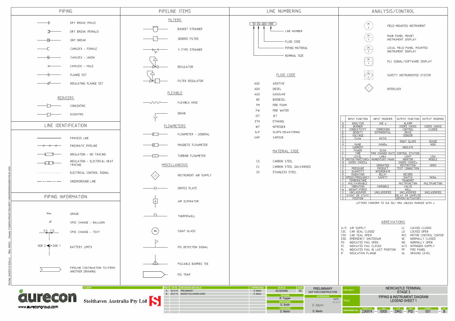
//////
F
M
E
NZW
LG
CLIENT REVISION DETAILSDATEREV APPROVED
DATE TITLE
CHECKED
APPROVED
PROJECT
DRAWN
DESIGNED
PROJECT No. TYPE REVWBS DISC NUMBER
DRAWING No.
SCALE SIZE
A3
.
NEWCASTLE TERMINALSTAGE 3
PIPING & INSTRUMENT DIAGRAMLEGEND SHEET 1
236974 0000 DRG PID 001 B
AS SHOWNPRELIMINARY
NOT FOR CONSTRUCTION
R. Tupper
D. Smith
D. Martin D. Martin
A 03.12.14 PRELIMINARY D. MartinB 09.01.15 ISSUED FOLLOWING HAZID D. Martin
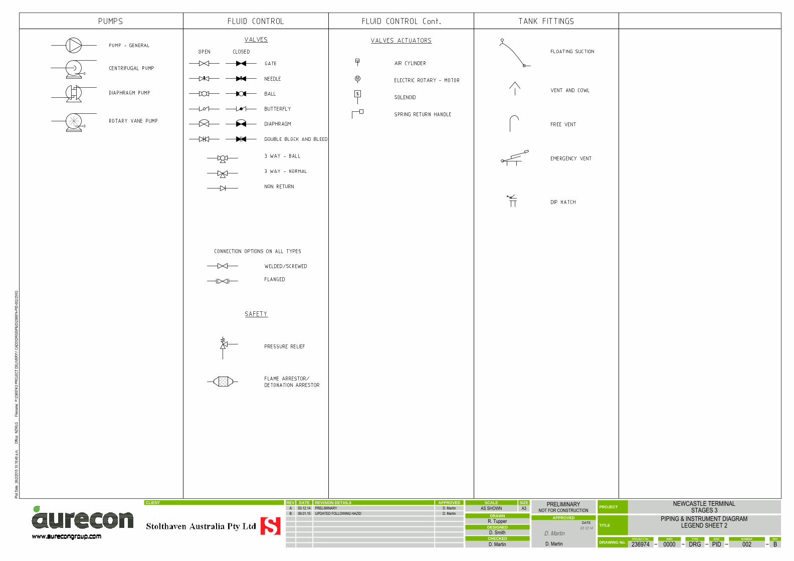
M
CLIENT REVISION DETAILSDATEREV APPROVED
DATE TITLE
CHECKED
APPROVED
PROJECT
DRAWN
DESIGNED
PROJECT No. TYPE REVWBS DISC NUMBER
DRAWING No.
SCALE SIZE
A3
.
NEWCASTLE TERMINALSTAGES 3
PIPING & INSTRUMENT DIAGRAMLEGEND SHEET 2
236974 0000 DRG PID 002 B
AS SHOWNPRELIMINARY
NOT FOR CONSTRUCTION
R. Tupper
D. Smith
D. Martin D. Martin
A 03.12.14 PRELIMINARY D. MartinB 09.01.15 UPDATED FOLLOWING HAZID D. Martin
NZW
LG
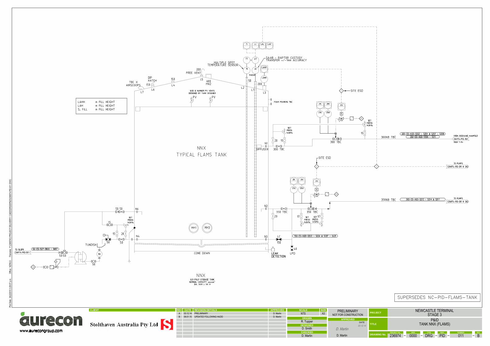
³
CLIENT REVISION DETAILSDATEREV APPROVED
DATE TITLE
CHECKED
APPROVED
PROJECT
DRAWN
DESIGNED
PROJECT No. TYPE REVWBS DISC NUMBER
DRAWING No.
SCALE SIZE
A3
.
NEWCASTLE TERMINALSTAGE 3
P&IDTANK NNX (FLAMS)
236974 0000 DRG PID 011 B
NTSPRELIMINARY
NOT FOR CONSTRUCTION
R. Tupper
D. Smith
D. Martin D. Martin
A 03.12.14 PRELIMINARY D. MartinB 09.01.15 UPDATED FOLLOWING HAZID D. Martin
NZW
LG

³
CLIENT REVISION DETAILSDATEREV APPROVED
DATE TITLE
CHECKED
APPROVED
PROJECT
DRAWN
DESIGNED
PROJECT No. TYPE REVWBS DISC NUMBER
DRAWING No.
SCALE SIZE
A3
.
NEWCASTLE TERMINALSTAGE 3
P&IDTANK NNX (ETHANOL)
236974 0000 DRG PID 012 B
NTSPRELIMINARY
NOT FOR CONSTRUCTION
R. Tupper
D. Smith
D. Martin D. Martin
A 03.12.14 PRELIMINARY D. MartinB 09.01.15 UPDATED FOLLOWING HAZID D. Martin
NZW
LG
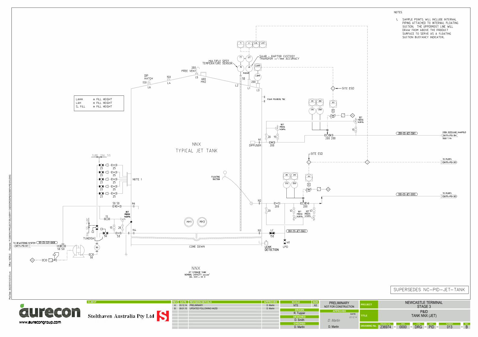
³
CLIENT REVISION DETAILSDATEREV APPROVED
DATE TITLE
CHECKED
APPROVED
PROJECT
DRAWN
DESIGNED
PROJECT No. TYPE REVWBS DISC NUMBER
DRAWING No.
SCALE SIZE
A3
.
NEWCASTLE TERMINALSTAGE 3
P&IDTANK NNX (JET)
236974 0000 DRG PID 013 B
NTSPRELIMINARY
NOT FOR CONSTRUCTION
R. Tupper
D. Smith
D. Martin D. Martin
A 03.12.14 PRELIMINARY D. MartinB 09.01.15 UPDATED FOLLOWING HAZID D. Martin
NZW
LG
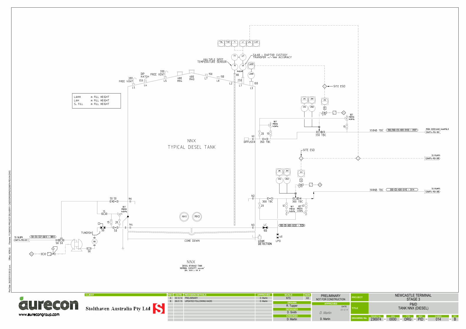
³
CLIENT REVISION DETAILSDATEREV APPROVED
DATE TITLE
CHECKED
APPROVED
PROJECT
DRAWN
DESIGNED
PROJECT No. TYPE REVWBS DISC NUMBER
DRAWING No.
SCALE SIZE
A3
.
NEWCASTLE TERMINALSTAGE 3
P&IDTANK NNX (DIESEL)
236974 0000 DRG PID 014 B
NTSPRELIMINARY
NOT FOR CONSTRUCTION
R. Tupper
D. Smith
D. Martin D. Martin
A 03.12.14 PRELIMINARY D. MartinB 09.01.15 UPDATED FOLLOWING HAZID D. Martin
NZW
LG

³
CLIENT REVISION DETAILSDATEREV APPROVED
DATE TITLE
CHECKED
APPROVED
PROJECT
DRAWN
DESIGNED
PROJECT No. TYPE REVWBS DISC NUMBER
DRAWING No.
SCALE SIZE
A3
.
NEWCASTLE TERMINALSTAGE 3
P&IDTANK NNX (FLAMS WITH VRU CONNECTION)
236974 0000 DRG PID 015 B
NTSPRELIMINARY
NOT FOR CONSTRUCTION
R. Tupper
D. Smith
D. Martin D. Martin
A 03.12.14 PRELIMINARY D. MartinB 09.01.15 UPDATED FOLLOWING HAZID D. Martin
NZW
LG
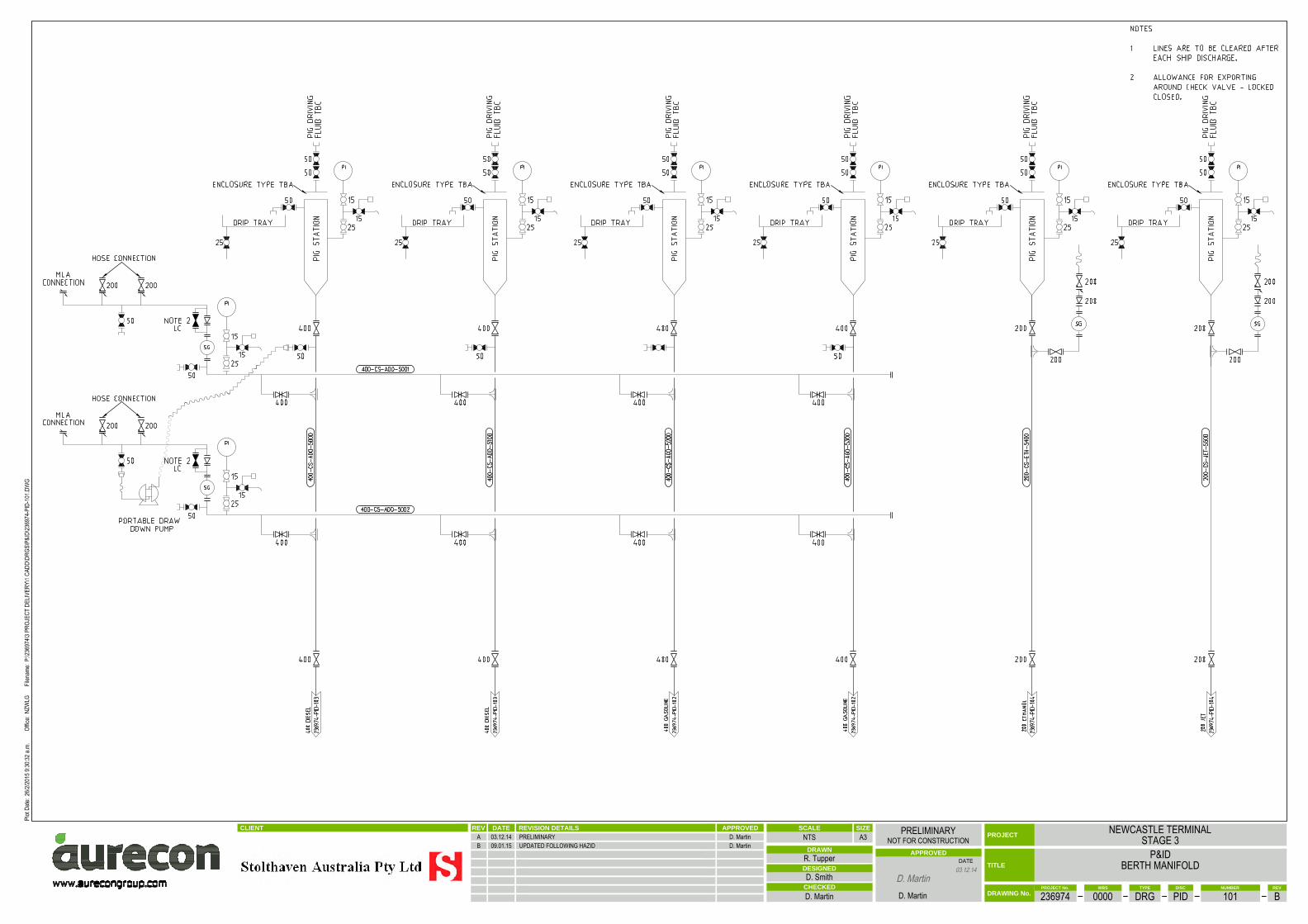
CLIENT REVISION DETAILSDATEREV APPROVED
DATE TITLE
CHECKED
APPROVED
PROJECT
DRAWN
DESIGNED
PROJECT No. TYPE REVWBS DISC NUMBER
DRAWING No.
SCALE SIZE
A3
.
NEWCASTLE TERMINALSTAGE 3
P&IDBERTH MANIFOLD
236974 0000 DRG PID 101 B
NTSPRELIMINARY
NOT FOR CONSTRUCTION
R. Tupper
D. Smith
D. Martin D. Martin
A 03.12.14 PRELIMINARY D. MartinB 09.01.15 UPDATED FOLLOWING HAZID D. Martin
NZW
LG
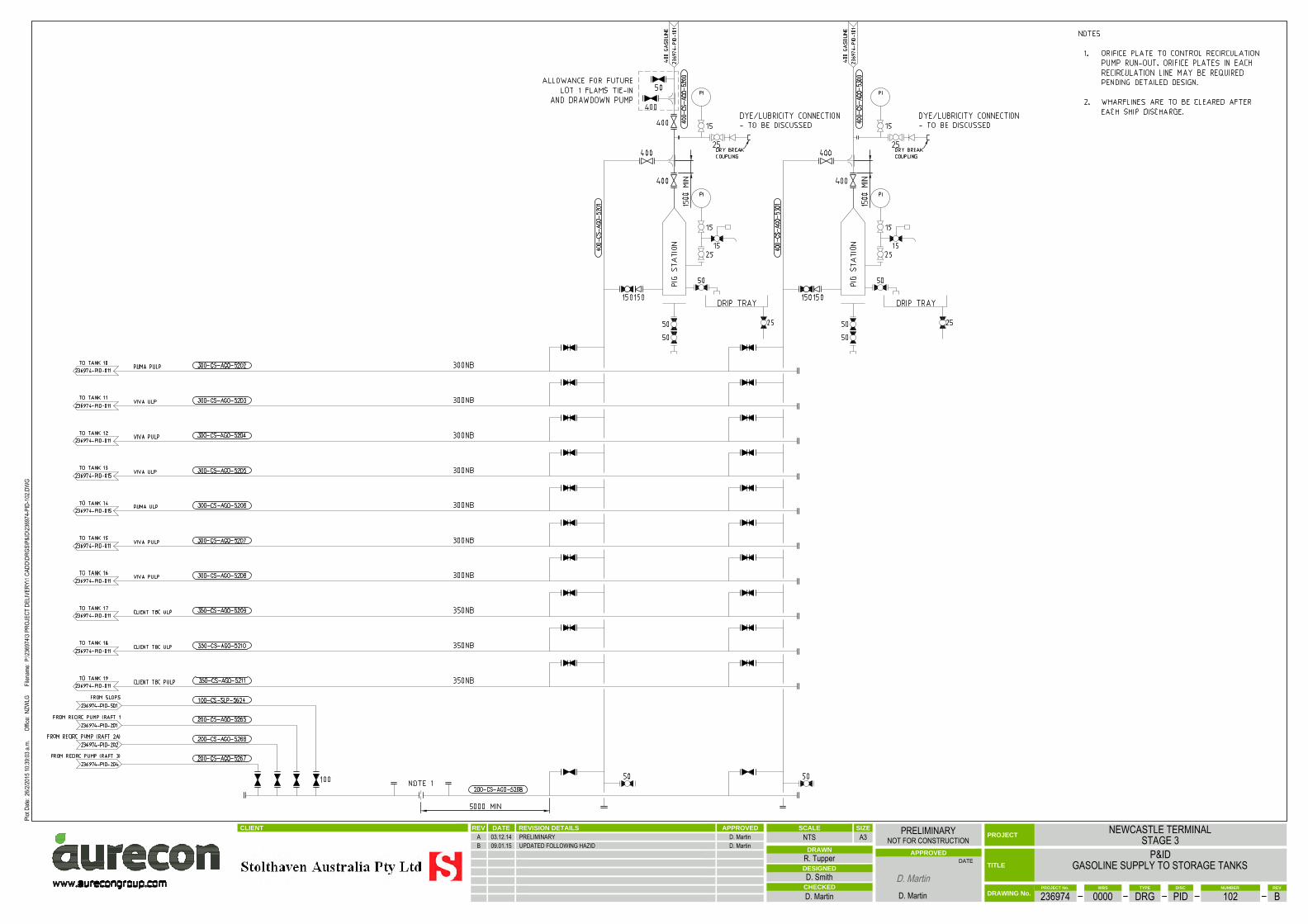
CLIENT REVISION DETAILSDATEREV APPROVED
DATE TITLE
CHECKED
APPROVED
PROJECT
DRAWN
DESIGNED
PROJECT No. TYPE REVWBS DISC NUMBER
DRAWING No.
SCALE SIZE
A3
.
NEWCASTLE TERMINALSTAGE 3
P&IDGASOLINE SUPPLY TO STORAGE TANKS
236974 0000 DRG PID 102 B
NTSPRELIMINARY
NOT FOR CONSTRUCTION
R. Tupper
D. Smith
D. Martin D. Martin
A 03.12.14 PRELIMINARY D. MartinB 09.01.15 UPDATED FOLLOWING HAZID D. Martin
NZW
LG

CLIENT REVISION DETAILSDATEREV APPROVED
DATE TITLE
CHECKED
APPROVED
PROJECT
DRAWN
DESIGNED
PROJECT No. TYPE REVWBS DISC NUMBER
DRAWING No.
SCALE SIZE
A3
.
NEWCASTLE TERMINALSTAGE 3
P&IDDIESEL SUPPLY TO STORAGE TANKS
236974 0000 DRG PID 103 B
NTSPRELIMINARY
NOT FOR CONSTRUCTION
R. Tupper
D. Smith
D. Martin D. Martin
A 03.12.14 PRELIMINARY D. MartinB 09.01.15 UPDATED FOLLOWING HAZID D. Martin
NZW
LG

CLIENT REVISION DETAILSDATEREV APPROVED
DATE TITLE
CHECKED
APPROVED
PROJECT
DRAWN
DESIGNED
PROJECT No. TYPE REVWBS DISC NUMBER
DRAWING No.
SCALE SIZE
A3
.
NEWCASTLE TERMINALSTAGE 3
P&IDETHANOL AND JET SUPPLY TO STORAGE TANKS
236974 0000 DRG PID 104 B
NTSPRELIMINARY
NOT FOR CONSTRUCTION
R. Tupper
D. Smith
D. Martin D. Martin
A 03.12.14 PRELIMINARY D. MartinB 09.01.15 UPDATED FOLLOWING HAZID D. Martin
NZW
LG

I
I
I
I
I
CLIENT REVISION DETAILSDATEREV APPROVED
DATE TITLE
CHECKED
APPROVED
PROJECT
DRAWN
DESIGNED
PROJECT No. TYPE REVWBS DISC NUMBER
DRAWING No.
SCALE SIZE
A3
.
NEWCASTLE TERMINALSTAGE 3
P&IDPUMP RAFT 1
GASOLINE SUCTION & DELIVERY
236974 0000 DRG PID 201 B
NTSPRELIMINARY
NOT FOR CONSTRUCTION
R. Tupper
D. Smith
D. Martin D. Martin
A 03.12.14 PRELIMINARY D. MartinB 09.01.15 UPDATED FOLLOWING HASID D. Martin
NZW
LG
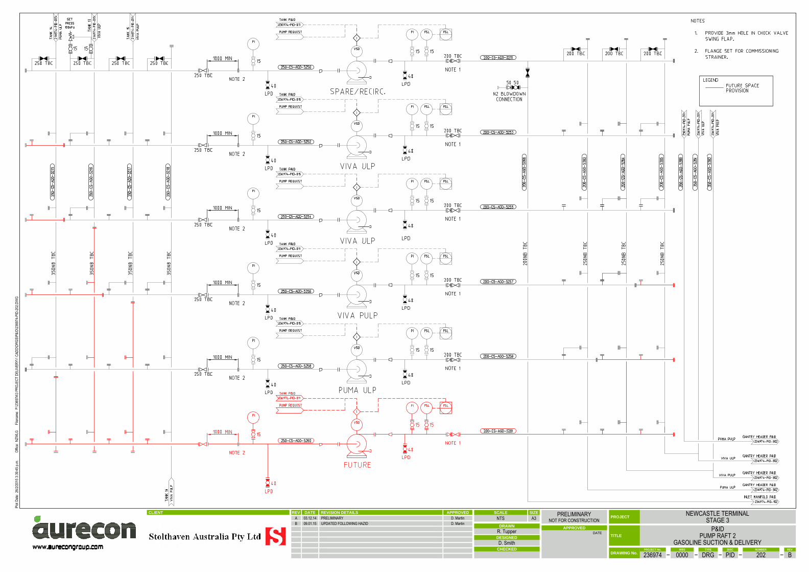
I
I
I
I
I
I
CLIENT REVISION DETAILSDATEREV APPROVED
DATE TITLE
CHECKED
APPROVED
PROJECT
DRAWN
DESIGNED
PROJECT No. TYPE REVWBS DISC NUMBER
DRAWING No.
SCALE SIZE
A3
.
NEWCASTLE TERMINALSTAGE 3
P&IDPUMP RAFT 2
GASOLINE SUCTION & DELIVERY
236974 0000 DRG PID 202 B
NTSPRELIMINARY
NOT FOR CONSTRUCTION
R. Tupper
D. Smith
A 03.12.14 PRELIMINARY D. MartinB 09.01.15 UPDATED FOLLOWING HAZID D. Martin
NZW
LG

I
I
I
I
CLIENT REVISION DETAILSDATEREV APPROVED
DATE TITLE
CHECKED
APPROVED
PROJECT
DRAWN
DESIGNED
PROJECT No. TYPE REVWBS DISC NUMBER
DRAWING No.
SCALE SIZE
A3
.
NEWCASTLE TERMINALSTAGE 3
P&IDPUMP RAFT 2
ETHANOL & JET SUCTION & DELIVERY
236974 0000 DRG PID 203 B
NTSPRELIMINARY
NOT FOR CONSTRUCTION
R. Tupper
D. Smith
D. Martin D. Martin
A 03.12.14 PRELIMINARY D. MartinB 09.01.15 UPDATED FOLLOWING HAZID D. Martin
NZW
LG
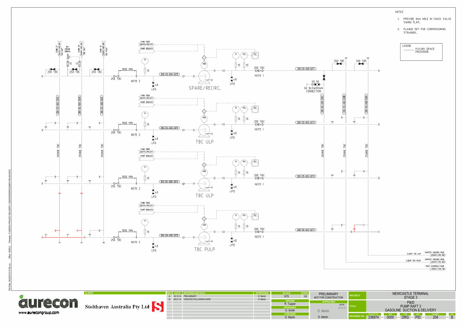
I
I
I
I
CLIENT REVISION DETAILSDATEREV APPROVED
DATE TITLE
CHECKED
APPROVED
PROJECT
DRAWN
DESIGNED
PROJECT No. TYPE REVWBS DISC NUMBER
DRAWING No.
SCALE SIZE
A3
.
NEWCASTLE TERMINALSTAGE 3
P&IDPUMP RAFT 3
GASOLINE SUCTION & DELIVERY
236974 0000 DRG PID 204 B
NTSPRELIMINARY
NOT FOR CONSTRUCTION
R. Tupper
D. Smith
D. Martin D. Martin
A 03.12.14 PRELIMINARY D. MartinB 09.01.15 UPDATED FOLLOWING HAZID D. Martin
NZW
LG
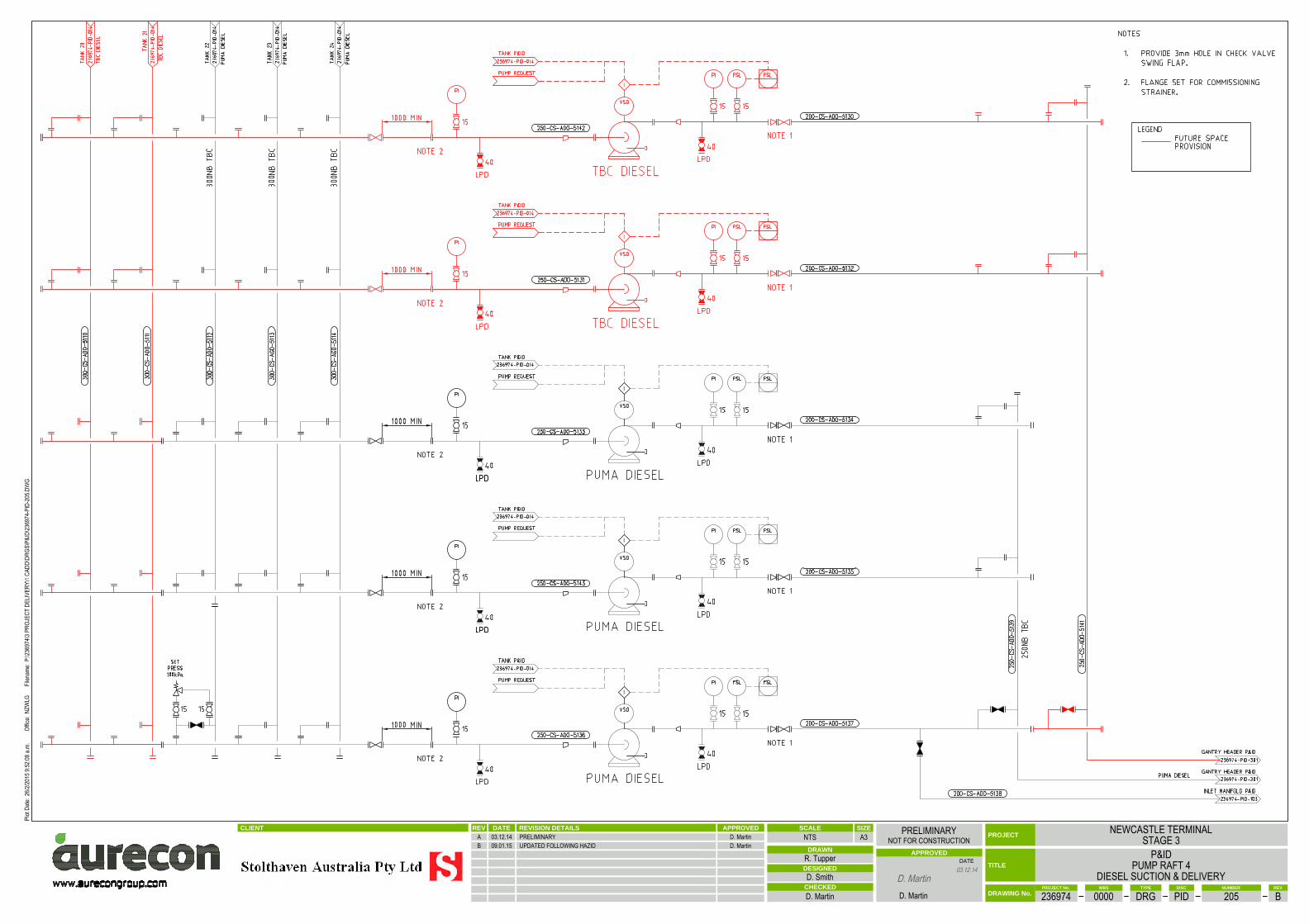
I
I
I
I
I
CLIENT REVISION DETAILSDATEREV APPROVED
DATE TITLE
CHECKED
APPROVED
PROJECT
DRAWN
DESIGNED
PROJECT No. TYPE REVWBS DISC NUMBER
DRAWING No.
SCALE SIZE
A3
.
NEWCASTLE TERMINALSTAGE 3
P&IDPUMP RAFT 4
DIESEL SUCTION & DELIVERY
236974 0000 DRG PID 205 B
NTSPRELIMINARY
NOT FOR CONSTRUCTION
R. Tupper
D. Smith
D. Martin D. Martin
A 03.12.14 PRELIMINARY D. MartinB 09.01.15 UPDATED FOLLOWING HAZID D. Martin
NZW
LG
CLIENT REVISION DETAILSDATEREV APPROVED
DATE TITLE
CHECKED
APPROVED
PROJECT
DRAWN
DESIGNED
PROJECT No. TYPE REVWBS DISC NUMBER
DRAWING No.
SCALE SIZE
A3
.
NEWCASTLE TERMINALSTAGE 3
P&IDGANTRY HEADERS
SHEET 1
236974 0000 DRG PID 301 B
NTSPRELIMINARY
NOT FOR CONSTRUCTION
R. Tupper
D. Smith
D. Martin D. Martin
A 03.12.14 PRELIMINARY D. MartinB 09.01.15 UPDATED FOLLOWING HAZID D. Martin
NZW
LG
CLIENT REVISION DETAILSDATEREV APPROVED
DATE TITLE
CHECKED
APPROVED
PROJECT
DRAWN
DESIGNED
PROJECT No. TYPE REVWBS DISC NUMBER
DRAWING No.
SCALE SIZE
A3
.
NEWCASTLE TERMINALSTAGE 3
P&IDGANTRY HEADERS
SHEET 2
236974 0000 DRG PID 302 B
NTSPRELIMINARY
NOT FOR CONSTRUCTION
R. Tupper
D. Smith
D. Martin D. Martin
A 03.12.14 PRELIMINARY D. MartinB 09.01.15 UPDATED FOLLOWING HAZID D. Martin
NZW
LG

F
F
F
F
F
F
CLIENT REVISION DETAILSDATEREV APPROVED
DATE TITLE
CHECKED
APPROVED
PROJECT
DRAWN
DESIGNED
PROJECT No. TYPE REVWBS DISC NUMBER
DRAWING No.
SCALE SIZE
A3
.
NEWCASTLE TERMINALSTAGE 3
P&IDTRUCK LOADING
BAY 1
236974 0000 DRG PID 401 B
NTSPRELIMINARY
NOT FOR CONSTRUCTION
R. Tupper
D. Smith
D. Martin D. Martin
A 03.12.14 PRELIMINARY D. MartinB 09.01.15 UPDATED FOLLOWING HAZID D. Martin
NZW
LG

F
F
F
F
F
F
CLIENT REVISION DETAILSDATEREV APPROVED
DATE TITLE
CHECKED
APPROVED
PROJECT
DRAWN
DESIGNED
PROJECT No. TYPE REVWBS DISC NUMBER
DRAWING No.
SCALE SIZE
A3
.
NEWCASTLE TERMINALSTAGE 3
P&IDTRUCK LOADING
BAY 2
236974 0000 DRG PID 402 B
NTSPRELIMINARY
NOT FOR CONSTRUCTION
R. Tupper
D. Smith
D. Martin D. Martin
A 03.12.14 PRELIMINARY D. MartinB 09.01.15 UPDATED FOLLOWING HAZID D. Martin
NZW
LG
F
F
F
F
F
F
CLIENT REVISION DETAILSDATEREV APPROVED
DATE TITLE
CHECKED
APPROVED
PROJECT
DRAWN
DESIGNED
PROJECT No. TYPE REVWBS DISC NUMBER
DRAWING No.
SCALE SIZE
A3
.
NEWCASTLE TERMINALSTAGE 3
P&IDTRUCK LOADING
BAY 3
236974 0000 DRG PID 403 B
NTSPRELIMINARY
NOT FOR CONSTRUCTION
R. Tupper
D. Smith
D. Martin D. Martin
A 03.12.14 PRELIMINARY D. MartinB 09.01.15 UPDATED FOLLOWING HAZID D. Martin
NZW
LG

F
F
F
F
F
F
CLIENT REVISION DETAILSDATEREV APPROVED
DATE TITLE
CHECKED
APPROVED
PROJECT
DRAWN
DESIGNED
PROJECT No. TYPE REVWBS DISC NUMBER
DRAWING No.
SCALE SIZE
A3
.
NEWCASTLE TERMINALSTAGE 3
P&IDTRUCK LOADING
BAY 4
236974 0000 DRG PID 404 B
NTSPRELIMINARY
NOT FOR CONSTRUCTION
R. Tupper
D. Smith
D. Martin D. Martin
A 03.12.14 PRELIMINARY D. MartinB 09.01.15 UPDATED FOLLOWING HAZID D. Martin
NZW
LG

CLIENT REVISION DETAILSDATEREV APPROVED
DATE TITLE
CHECKED
APPROVED
PROJECT
DRAWN
DESIGNED
PROJECT No. TYPE REVWBS DISC NUMBER
DRAWING No.
SCALE SIZE
A3
.
NEWCASTLE TERMINALSTAGE 3
P&IDDEWATERING AND SLOPS
236974 0000 DRG PID 501 A
NTSPRELIMINARY
NOT FOR CONSTRUCTION
R. Tupper
D. Smith
D. Martin D. Martin
A 03.12.14 PRELIMINARY D. Martin
NZW
LG
CLIENT REVISION DETAILSDATEREV APPROVED
DATE TITLE
CHECKED
APPROVED
PROJECT
DRAWN
DESIGNED
PROJECT No. TYPE REVWBS DISC NUMBER
DRAWING No.
SCALE SIZE
A3
.
NEWCASTLE TERMINALSTAGE 3
P&IDDRAINAGE
236974 0000 DRG PID 502 B
NTSPRELIMINARY
NOT FOR CONSTRUCTION
R. Tupper
D. Smith
D. Martin D. Martin
A 03.12.14 PRELIMINARY D. MartinB 09.01.15 UPDATED FOLLOWING HAZID D. Martin
NZW
LG

CLIENT REVISION DETAILSDATEREV APPROVED
DATE TITLE
CHECKED
APPROVED
PROJECT
DRAWN
DESIGNED
PROJECT No. TYPE REVWBS DISC NUMBER
DRAWING No.
SCALE SIZE
A3
.
NEWCASTLE TERMINALSTAGE 3
P&IDVAPOUR RECOVERY UNIT
236974 0000 DRG PID 601 B
NTSPRELIMINARY
NOT FOR CONSTRUCTION
R. Tupper
D. Smith
D. Martin D. Martin
A 03.12.14 PRELIMINARY D. MartinB 09.01.15 UPDATED FOLLOWING HAZID D. Martin
NZW
LG

CLIENT REVISION DETAILSDATEREV APPROVED
DATE TITLE
CHECKED
APPROVED
PROJECT
DRAWN
DESIGNED
PROJECT No. TYPE REVWBS DISC NUMBER
DRAWING No.
SCALE SIZE
A3
.
NEWCASTLE TERMINALSTAGE 3
P&IDSTAGE 3 DIESEL TIE-IN TO EXISTING STAGE 1
236974 0000 DRG SK 105 B
NTSPRELIMINARY
NOT FOR CONSTRUCTION
R. Tupper
D. Smith
D. Martin D. Martin
A 03.12.14 PRELIMINARY D. MartinB 09.01.15 UPDATED FOLLOWING HAZID D. Martin
NZW
LG

Appendix B: Drawings (Second HAZOP 2/3/4 May 2016))
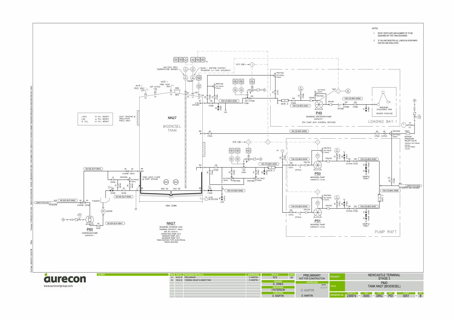
NOTES
1. ROOF VENTS SIZE AND NUMBER OF TO BEDESIGNED BY THE TANK DESIGNER.
2. 'E' ON LINE DENOTES ALL LINES/VALVES/PUMPSHEATED AND INSULATED.
OPERATING TEMP: 25°CMINIMUM TEMP: 20°CMAXIMUM TEMP: 30°C
TANK HEATING TYPE: ELECTRICALTRACE HEATING
BYPASSPRESSURERELIEF VALVE
CLIENT REVISION DETAILSDATEREV APPROVED
DATE TITLE
CHECKED
APPROVED
PROJECT
DRAWN
DESIGNED
PROJECT No. TYPE REVWBS DISC NUMBER
DRAWING No.
SCALE SIZE
A3
.
NEWCASTLE TERMINALSTAGE 3
P&IDTANK NN27 (BIODIESEL)
236974 0000 DRG PID 0051 B
NTSPRELIMINARY
NOT FOR CONSTRUCTION
D. JONES
I.PATERSON
D. MARTIN D. MARTIN
D. MARTIN03.12.14
A 24.03.16 PRELIMINARY D. MARTINB 18.04.16 THERMAL RELIEF & SMART P&ID D. MARTIN
Filen
ame:
Plot
Date:
Offic
e:P:
\PRO
JECT
S\11
2591
236
974-
STOL
THAV
EN -
STAG
E 3 D
ESIG
N\03
PRJ
DEL
\1 DW
G MA
N\11
2591
2369
74 S
TOLT
HAVE
N III
SMAR
T P&
IDS\
PID
DWG\
2369
74-0
000-
DRG-
PID-
0051
.DW
G28
/4/20
16 1:
56:06
PM

BYPASSPRESSURERELIEF VALVE
CLIENT REVISION DETAILSDATEREV APPROVED
DATE TITLE
CHECKED
APPROVED
PROJECT
DRAWN
DESIGNED
PROJECT No. TYPE REVWBS DISC NUMBER
DRAWING No.
SCALE SIZE
A3
.
NEWCASTLE TERMINALSTAGE 3
P&IDTANK ND28 (PUMA ADDITIVE)
236974 0000 DRG PID 0052 B
NTSPRELIMINARY
NOT FOR CONSTRUCTION
D. JONES
I.PATERSON
D. MARTIN D. MARTIN
D. MARTIN03.12.14
A 24.03.16 PRELIMINARY D. MARTINB 18.04.16 THERMAL RELIEF & SMART P&ID D. MARTIN
Filen
ame:
Plot
Date:
Offic
e:P:
\PRO
JECT
S\11
2591
236
974-
STOL
THAV
EN -
STAG
E 3 D
ESIG
N\03
PRJ
DEL
\1 DW
G MA
N\11
2591
2369
74 S
TOLT
HAVE
N III
SMAR
T P&
IDS\
PID
DWG\
2369
74-0
000-
DRG-
PID-
0052
.DW
G28
/4/20
16 1:
58:44
PM
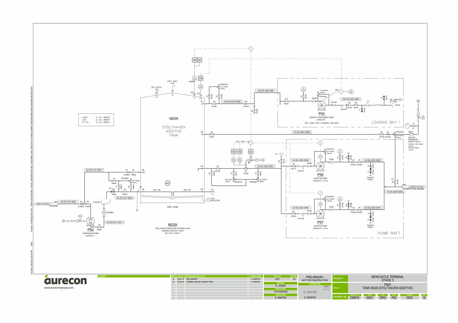
BYPASSPRESSURERELIEF VALVE
CLIENT REVISION DETAILSDATEREV APPROVED
DATE TITLE
CHECKED
APPROVED
PROJECT
DRAWN
DESIGNED
PROJECT No. TYPE REVWBS DISC NUMBER
DRAWING No.
SCALE SIZE
A3
.
NEWCASTLE TERMINALSTAGE 3
P&IDTANK ND29 (STOLTHAVEN ADDITIVE)
236974 0000 DRG PID 0053 B
NTSPRELIMINARY
NOT FOR CONSTRUCTION
D. JONES
I.PATERSON
D. MARTIN D. MARTIN
D. MARTIN03.12.14
A 24.03.16 PRELIMINARY D. MARTINB 18.04.16 THERMAL RELIEF & SMART P&ID D. MARTIN
Filen
ame:
Plot
Date:
Offic
e:P:
\PRO
JECT
S\11
2591
236
974-
STOL
THAV
EN -
STAG
E 3 D
ESIG
N\03
PRJ
DEL
\1 DW
G MA
N\11
2591
2369
74 S
TOLT
HAVE
N III
SMAR
T P&
IDS\
PID
DWG\
2369
74-0
000-
DRG-
PID-
0053
.DW
G28
/4/20
16 2:
00:44
PM

CLIENT REVISION DETAILSDATEREV APPROVED
DATE TITLE
CHECKED
APPROVED
PROJECT
DRAWN
DESIGNED
PROJECT No. TYPE REVWBS DISC NUMBER
DRAWING No.
SCALE SIZE
A3
.
NEWCASTLE TERMINALSTAGE 3
P&IDDEWATERING AND SLOPS
236974 0000 DRG PID 0501 E
NTSPRELIMINARY
NOT FOR CONSTRUCTION
D. JONES
D. SMITH
D. MARTIN D. MARTIN
D. MARTIN03.12.14
A 03.12.14 PRELIMINARY D. MARTINB 10.04.15 RETURN LINE TO INLET MANIFOLD REMOVED D. MARTINC 30.09.15 DEWATERING TANK REMOVED D. MARTIND 22.02.16 GENERAL UPDATE D. MARTINE 20.04.16 THERMAL RELIEF & SMART P&ID D. MARTIN
Filen
ame:
Plot
Date:
Offic
e:P:
\PRO
JECT
S\11
2591
236
974-
STOL
THAV
EN -
STAG
E 3 D
ESIG
N\03
PRJ
DEL
\1 DW
G MA
N\11
2591
2369
74 S
TOLT
HAVE
N III
SMAR
T P&
IDS\
PID
DWG\
2369
74-0
000-
DRG-
PID-
0501
.DW
G28
/4/20
16 4:
45:31
PM

NOTES:
1. ALL BUND COMPOUND SUMPS INCLUDE TURN-DOWN/FLAME TRAPS
2. PURACEPTOR BALL FLOAT WILL MAINTAIN AT HYDROCARBON/WATER INTERFACE AND WILLSHUT OFF FLOW ONCE UNIT REACHES HYDROCARBON MAXIMUM RETENTION CAPACITY.
3. PURACEPTOR OIL-SETPROBE WILL DETECT HYDROCARBONS AT A SET LEVEL WITHIN THEPURACEPTOR. THIS LEVEL WILL BE SET DURING COMMISSIONING.
4. VENT PIPES SHALL NOT BE INTER-CONNECTED AND SHALL HAVE STACK HEIGHT 4.0mHIGH AT A MINIMUM. VENT PIPES ABOVE GROUND SHALL BE A MINIMUM OF 40mmØGALVANISED STEEL WITH A SOLID TOP PROTECTIVE CAGE.
5. PURACEPTOR LIDS SHALL BE LOCK-DOWN 600x900 CLASS D RATED LIDS.
6. ANY HYDRCARBON SPILLS LARGER THAN PURACEPTOR CAPACITY WILL SHUT-OFF FLOWAND WILL BE CONTAINED IN THE PURACEPTOR. PIPE NETWORK AND BUND COMPOUND.
7. PURACEPTOR LID TO BE SEALED ACCORDING TO SUPPLIER REQUIREMENTS.
CLIENT REVISION DETAILSDATEREV APPROVED
DATE TITLE
CHECKED
APPROVED
PROJECT
DRAWN
DESIGNED
PROJECT No. TYPE REVWBS DISC NUMBER
DRAWING No.
SCALE SIZE
A3
.
NEWCASTLE TERMINALSTAGE 3
P&IDDRAINAGE
236974 0000 DRG PID 0502 D
NTSPRELIMINARY
NOT FOR CONSTRUCTION
D. JONES
D. SMITH
D. MARTIN D. MARTIN
D. MARTIN03.12.14
A 03.12.14 PRELIMINARY D. MARTINB 09.01.15 UPDATED FOLLOWING HAZID D. MARTINC 10.04.15 PIPING MODIFIED D. MARTIND 27.04.16 THERMAL RELIEF & SMART P&ID
Filen
ame:
Plot
Date:
Offic
e:P:
\PRO
JECT
S\11
2591
236
974-
STOL
THAV
EN -
STAG
E 3 D
ESIG
N\03
PRJ
DEL
\1 DW
G MA
N\11
2591
2369
74 S
TOLT
HAVE
N III
SMAR
T P&
IDS\
PID
DWG\
2369
74-0
000-
DRG-
PID-
0502
.DW
G28
/4/20
16 1:
50:20
PM

NC-PID-1503
200
200
VACUUM PUMP
VACUUM PUMP
CLIENT REVISION DETAILSDATEREV APPROVED
DATE TITLE
CHECKED
APPROVED
PROJECT
DRAWN
DESIGNED
PROJECT No. TYPE REVWBS DISC NUMBER
DRAWING No.
SCALE SIZE
A3
.
NEWCASTLE TERMINALSTAGE 3
P&IDVAPOUR RECOVERY UNIT
236974 0000 DRG PID 0601 E
NTSPRELIMINARY
NOT FOR CONSTRUCTION
D. JONES
D. SMITH
D. MARTIN D. MARTIN
D. MARTIN03.12.14
A 03.12.14 PRELIMINARY D. MARTINB 09.01.15 UPDATED FOLLOWING HAZID D. MARTINC 10.04.15 VRU VENT ADDED D. MARTIND 22.02.16 GENERAL UPDATE D. MARTINE 20.04.16 THERMAL RELIEF & SMART P&ID D. MARTIN
Filen
ame:
Plot
Date:
Offic
e:P:
\PRO
JECT
S\11
2591
236
974-
STOL
THAV
EN -
STAG
E 3 D
ESIG
N\03
PRJ
DEL
\1 DW
G MA
N\11
2591
2369
74 S
TOLT
HAVE
N III
SMAR
T P&
IDS\
PID
DWG\
2369
74-0
000-
DRG-
PID-
0601
.DW
G28
/4/20
16 11
:09:49
AM

Appendix C: Probability Bow‐Ties (Newcastle Terminal Stage 3)
List of Probability Bow‐Ties:
Logistic Summary Legend Figure B.1 (LHS) LOC Wharf & Pipelines ‐ ULP/PULP Discharge Figure B.1 (RHS) LOC Wharf & Pipelines ‐ ULP/PULP Discharge Figure B.2 (LHS) LOC Wharf & Pipelines – Ethanol Discharge Figure B.2 (RHS) LOC Wharf & Pipelines – Ethanol Discharge Figure B.3 (LHS) LOC Wharf & Pipelines ‐ Jet Fuel Discharge Figure B.3 (RHS) LOC Wharf & Pipelines ‐ Jet Fuel Discharge Figure B.4 (LHS) LOC Wharf & Pipelines – Diesel/Biodiesel Discharge Figure B.4 (RHS) LOC Wharf & Pipelines ‐ Diesel/Biodiesel Discharge Figure B.5 (LHS) LOC Wharf & Pipelines – Black Products Discharge Figure B.5 (RHS) LOC Wharf & Pipelines – Black Products Discharge Figure B.6 (LHS) Storage Tanks Loss of Containment Liquid (ULP/PULP) Figure B.6 (RHS) Storage Tanks Loss of Containment Liquid (ULP/PULP, Large) Figure B.6 (RHS) Storage Tanks Loss of Containment Liquid (ULP/PULP, Moderate) Figure B.7 (LHS) Storage Tanks Loss of Containment (Ethanol) Figure B.7 (RHS) Storage Tanks Loss of Containment (Ethanol) Figure B.8 (LHS) Storage Tanks Loss of Containment (Jet) Figure B.8 (RHS) Storage Tanks Loss of Containment (Jet) Figure B.9 (LHS) Storage Tanks Loss of Containment (Diesel/Biodiesel) Figure B.9 (RHS) Storage Tanks Loss of Containment (Diesel/Biodiesel) Figure B.10 (LHS) Storage Tanks Fire & Explosion (Petrol) Figure B.10 (RHS) Storage Tanks Fire & Explosion (Petrol) Figure B.11 (LHS) Storage Tanks Fire & Explosion (Ethanol) Figure B.11 (RHS) Storage Tanks Fire & Explosion (Ethanol) Figure B.12 (LHS) Storage Tanks Fire & Explosion (Jet Fuel) Figure B.12 (RHS) Storage Tanks Fire & Explosion (Jet Fuel) Figure B.13 (LHS) Storage Tanks Fire & Explosion (Diesel/Biodiesel) Figure B.13 (RHS) Storage Tanks Fire & Explosion (Diesel/Biodiesel) Figure B.14 (LHS) RTFS (South) Fire & Explosion Figure B.14 (RHS) RTFS (South) Fire & Explosion Figure B.15 (LHS) RTFS (South) Loss of Containment Liquid Figure B.15 (RHS) RTFS (South) Loss of Containment Liquid Figure B.16 (LHS) RTFS (South) Loss of Containment Vapour Figure B.16 (RHS) RTFS (South) Loss of Containment Vapour Figure B.17 (LHS) RTFS (North) Fire & Explosion Figure B.17 (RHS) RTFS (North) Fire & Explosion Figure B.18 (LHS) RTFS (North) Loss of Containment Liquid Figure B.18 (RHS) RTFS (North) Loss of Containment Liquid Figure B.19 (LHS) RTFS (North) Loss of Containment Vapour Figure B.19 (RHS) RTFS (North) Loss of Containment Vapour Figure B.20 (LHS) Vapour Recovery Unit Figure B.20 (LHS) Vapour Recovery Unit Figure B.21 (LHS) Pump Bays & VRU Bund FigureB.21 (RHS) Pump Bays & VRU Bund Figure B.22 (LHS) Additives & Slops Tanks FigureB.22 (RHS) Additives & Slops Tanks QRA Summary

Appendix C Heat Radiation Exposure
Consequences of Heat Radiation
The table below is reproduced from the New South Wales Hazardous Industry Planning Advisory Paper No 2: Fire Safety Study Guidelines, Appendix 8 and presents the potential consequences of thermal radiation exposure for use in the preparation of Fire Safety Studies and Risk Assessments. Radiant Heat Exposure Impairment Criteria
Radiation Intensity (kW/m2) Effect
1.2 Received from the sun at noon in summer
2.1 Minimum to cause pain in one minute
4.7 Will cause pain in 15 – 20 seconds and injury after 30 seconds exposure (likely second degree burn injury)
12.6
Significant chance of fatality for long exposure. High chance of injury Causes the temperature of wood to rise to a temperature where it will be ignited with a naked flame after long exposure Thin steel with insulation on the side away from the fire may reach a thermal stress level high enough to cause structural failure
23
Likely fatality for extended exposure and chance of fatality for instantaneous exposure Spontaneous ignition of wood after long exposure Unprotected steel will reach thermal stress causing failure Pressure vessels will need to be relieved or failure will occur
35 Cellulose material will pilot ignite with one minute exposure Significant chance of fatality if people are exposed instantaneously
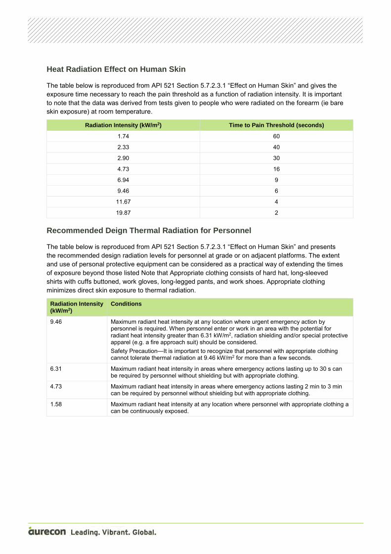
Heat Radiation Effect on Human Skin
The table below is reproduced from API 521 Section 5.7.2.3.1 “Effect on Human Skin” and gives the exposure time necessary to reach the pain threshold as a function of radiation intensity. It is important to note that the data was derived from tests given to people who were radiated on the forearm (ie bare skin exposure) at room temperature.
Radiation Intensity (kW/m2) Time to Pain Threshold (seconds)
1.74 60
2.33 40
2.90 30
4.73 16
6.94 9
9.46 6
11.67 4
19.87 2 Recommended Deign Thermal Radiation for Personnel
The table below is reproduced from API 521 Section 5.7.2.3.1 “Effect on Human Skin” and presents the recommended design radiation levels for personnel at grade or on adjacent platforms. The extent and use of personal protective equipment can be considered as a practical way of extending the times of exposure beyond those listed Note that Appropriate clothing consists of hard hat, long-sleeved shirts with cuffs buttoned, work gloves, long-legged pants, and work shoes. Appropriate clothing minimizes direct skin exposure to thermal radiation.
Radiation Intensity (kW/m2)
Conditions
9.46 Maximum radiant heat intensity at any location where urgent emergency action by personnel is required. When personnel enter or work in an area with the potential for radiant heat intensity greater than 6.31 kW/m2, radiation shielding and/or special protective apparel (e.g. a fire approach suit) should be considered. Safety Precaution—It is important to recognize that personnel with appropriate clothing cannot tolerate thermal radiation at 9.46 kW/m2 for more than a few seconds.
6.31 Maximum radiant heat intensity in areas where emergency actions lasting up to 30 s can be required by personnel without shielding but with appropriate clothing.
4.73 Maximum radiant heat intensity in areas where emergency actions lasting 2 min to 3 min can be required by personnel without shielding but with appropriate clothing.
1.58 Maximum radiant heat intensity at any location where personnel with appropriate clothing a can be continuously exposed.

Appendix D AS 1940 and Consequence Modelling Results
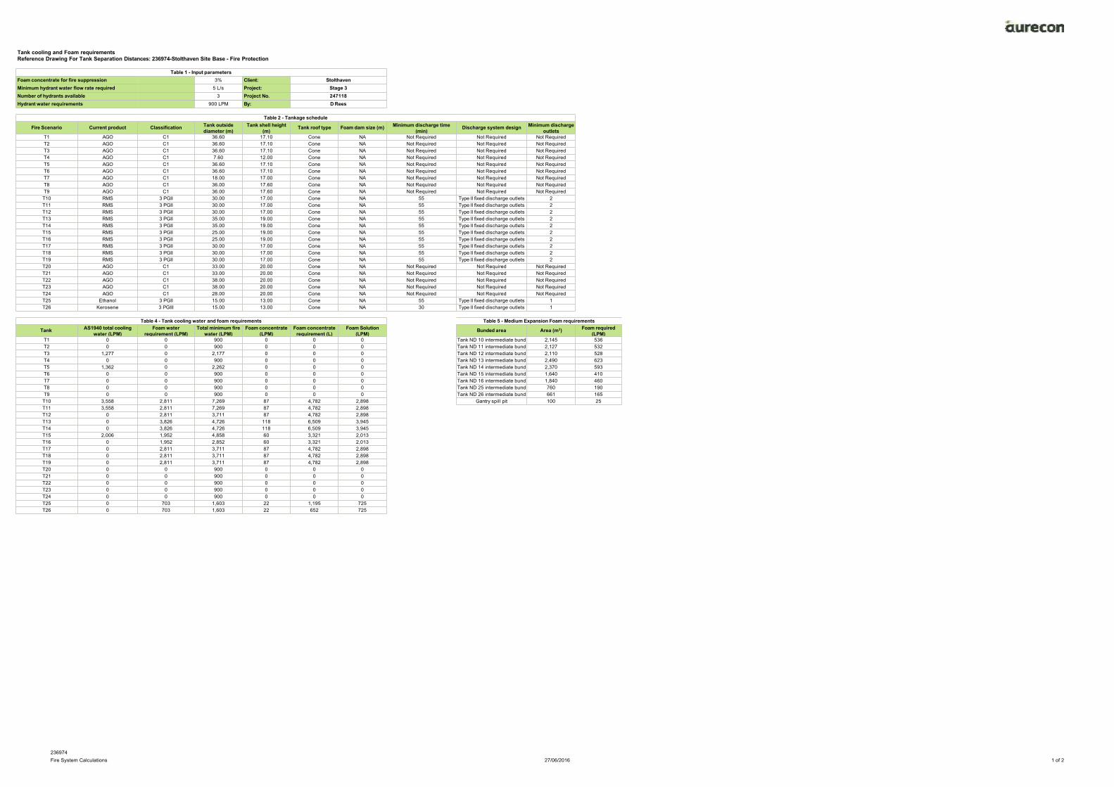
236974Fire System Calculations 27/06/2016 1 of 2
Tank cooling and Foam requirementsReference Drawing For Tank Separation Distances: 236974-Stolthaven Site Base - Fire Protection
Table 1 - Input parametersFoam concentrate for fire suppression 3% Client: StolthavenMinimum hydrant water flow rate required 5 L/s Project: Stage 3Number of hydrants available 3 Project No. 247118Hydrant water requirements 900 LPM By: D Rees
Table 2 - Tankage schedule
Fire Scenario Current product Classification Tank outsidediameter (m)
Tank shell height(m)
Tank roof type Foam dam size (m) Minimum discharge time(min)
Discharge system design Minimum dischargeoutlets
T1 AGO C1 36.60 17.10 Cone NA Not Required Not Required Not RequiredT2 AGO C1 36.60 17.10 Cone NA Not Required Not Required Not RequiredT3 AGO C1 36.60 17.10 Cone NA Not Required Not Required Not RequiredT4 AGO C1 7.60 12.00 Cone NA Not Required Not Required Not RequiredT5 AGO C1 36.60 17.10 Cone NA Not Required Not Required Not RequiredT6 AGO C1 36.60 17.10 Cone NA Not Required Not Required Not RequiredT7 AGO C1 18.00 17.00 Cone NA Not Required Not Required Not RequiredT8 AGO C1 36.00 17.60 Cone NA Not Required Not Required Not RequiredT9 AGO C1 36.00 17.60 Cone NA Not Required Not Required Not Required
T10 RMS 3 PGII 30.00 17.00 Cone NA 55 Type II fixed discharge outlets 2T11 RMS 3 PGII 30.00 17.00 Cone NA 55 Type II fixed discharge outlets 2T12 RMS 3 PGII 30.00 17.00 Cone NA 55 Type II fixed discharge outlets 2T13 RMS 3 PGII 35.00 19.00 Cone NA 55 Type II fixed discharge outlets 2T14 RMS 3 PGII 35.00 19.00 Cone NA 55 Type II fixed discharge outlets 2T15 RMS 3 PGII 25.00 19.00 Cone NA 55 Type II fixed discharge outlets 2T16 RMS 3 PGII 25.00 19.00 Cone NA 55 Type II fixed discharge outlets 2T17 RMS 3 PGII 30.00 17.00 Cone NA 55 Type II fixed discharge outlets 2T18 RMS 3 PGII 30.00 17.00 Cone NA 55 Type II fixed discharge outlets 2T19 RMS 3 PGII 30.00 17.00 Cone NA 55 Type II fixed discharge outlets 2T20 AGO C1 33.00 20.00 Cone NA Not Required Not Required Not RequiredT21 AGO C1 33.00 20.00 Cone NA Not Required Not Required Not RequiredT22 AGO C1 38.00 20.00 Cone NA Not Required Not Required Not RequiredT23 AGO C1 38.00 20.00 Cone NA Not Required Not Required Not RequiredT24 AGO C1 28.00 20.00 Cone NA Not Required Not Required Not RequiredT25 Ethanol 3 PGII 15.00 13.00 Cone NA 55 Type II fixed discharge outlets 1T26 Kerosene 3 PGIII 15.00 13.00 Cone NA 30 Type II fixed discharge outlets 1
Table 4 - Tank cooling water and foam requirements Table 5 - Medium Expansion Foam requirements
Tank AS1940 total coolingwater (LPM)
Foam waterrequirement (LPM)
Total minimum firewater (LPM)
Foam concentrate(LPM)
Foam concentraterequirement (L)
Foam Solution(LPM)
Bunded area Area (m2) Foam required(LPM)
T1 0 0 900 0 0 0 Tank ND 10 intermediate bund 2,145 536T2 0 0 900 0 0 0 Tank ND 11 intermediate bund 2,127 532T3 1,277 0 2,177 0 0 0 Tank ND 12 intermediate bund 2,110 528T4 0 0 900 0 0 0 Tank ND 13 intermediate bund 2,490 623T5 1,362 0 2,262 0 0 0 Tank ND 14 intermediate bund 2,370 593T6 0 0 900 0 0 0 Tank ND 15 intermediate bund 1,640 410T7 0 0 900 0 0 0 Tank ND 16 intermediate bund 1,840 460T8 0 0 900 0 0 0 Tank ND 25 intermediate bund 760 190T9 0 0 900 0 0 0 Tank ND 26 intermediate bund 661 165
T10 3,558 2,811 7,269 87 4,782 2,898 Gantry spill pit 100 25T11 3,558 2,811 7,269 87 4,782 2,898T12 0 2,811 3,711 87 4,782 2,898T13 0 3,826 4,726 118 6,509 3,945T14 0 3,826 4,726 118 6,509 3,945T15 2,006 1,952 4,858 60 3,321 2,013T16 0 1,952 2,852 60 3,321 2,013T17 0 2,811 3,711 87 4,782 2,898T18 0 2,811 3,711 87 4,782 2,898T19 0 2,811 3,711 87 4,782 2,898T20 0 0 900 0 0 0T21 0 0 900 0 0 0T22 0 0 900 0 0 0T23 0 0 900 0 0 0T24 0 0 900 0 0 0T25 0 703 1,603 22 1,195 725T26 0 703 1,603 22 652 725

236974Fire System Calculations 27/06/2016 2 of 2
Table 6 - Tank cooling water flowrate calculation
Tank on Fire(TOF)
Tank at Risk(TAR)
Diameter of TOF (D)(m)
Diameter of TAR(m)
Height of TAR(m)
TOF centre to TARcentre distance
(mm)
Shell to shellseparation
distance (S)(m)
S/D ratio Shell cooling required? Roof coolingrequired?
Rate of coolingrequired for
projected area oftank, (W)(LPM/m2)
AS 1940 Shell Cooling(LPM)
Consequence heatradiated (kW/m2) -
EDITED FROM RAW TOONLY INCL. > 8kW/m2
ConsequenceShell Cooling
(LPM)
ConsequenceCooling Density
(LPM/m2)
ConsequenceRoof Cooling
(LPM)
ConsequenceRoof angle
AS1940 RoofCooling Density
(LPM/m2)
AS1940 RoofCooling(LPM)
Design ShellCooling
Flowrate (LPM)
Design RoofCooling Flowrate
(LPM)
Total CoolingFlowrate (LPM)
T10 T11 30.00 30.00 17.00 45,000 15.0 0.50 Yes Yes 4.44 2,469 15 1,510 2.6 666 120° 4.24 1089 2,469 1,089 3,558T10 T15 30.00 25.00 19.00 49,124 21.6 0.72 Yes Yes 2.92 1,509 10.3 966 1.8 318 120° 2.78 496 1,509 496 2,006T10 T3 30.00 36.60 17.10 65,065 31.8 1.06 Yes No 1.87 1,277 0 0 0.0 0 0° 1.79 0 1,277 0 1,277T10 T5 30.00 36.60 17.10 63,346 30.0 1.00 Yes No 2.00 1,362 0 0 0.0 0 0° 1.91 0 1,362 0 1,362T11 T10 30.00 30.00 17.00 45,000 15.0 0.50 Yes Yes 4.44 2,469 15 1,510 2.6 666 120° 4.24 1089 2,469 1,089 3,558T11 T12 30.00 30.00 17.00 45,000 15.0 0.50 Yes Yes 4.44 2,469 15 1,510 2.6 666 120° 4.24 1089 2,469 1,089 3,558T11 T14 30.00 35.00 19.00 72,118 39.6 1.32 Yes No 1.45 1,053 0 0 0.0 0 0° 1.39 0 1,053 0 1,053T11 T15 30.00 25.00 19.00 56,517 29.0 0.97 Yes Yes 2.08 1,076 0 0 0.0 0 0° 1.98 354 1,076 354 1,430T11 T2 30.00 36.60 17.10 66,730 33.4 1.11 Yes No 1.77 1,204 0 0 0.0 0 0° 1.69 0 1,204 0 1,204T11 T25 30.00 15.00 13.00 43,469 21.0 0.70 Yes Yes 3.02 642 8.2 316 1.4 91 120° 2.88 185 642 185 827T11 T3 30.00 36.60 17.10 61,809 28.5 0.95 Yes Yes 2.12 1,447 0 0 0.0 0 0° 2.03 774 1,447 774 2,221T12 T1 30.00 36.60 17.10 68,568 35.3 1.18 Yes No 1.66 1,132 0 0 0.0 0 0° 1.59 0 1,132 0 1,132T12 T11 30.00 30.00 17.00 45,000 15.0 0.50 Yes Yes 4.44 2,469 15 1,510 2.6 666 120° 4.24 1089 2,469 1,089 3,558T12 T14 30.00 35.00 19.00 52,167 19.7 0.66 Yes Yes 3.25 2,357 12 1,575 2.1 725 120° 3.10 1085 2,357 1,085 3,442T12 T2 30.00 36.60 17.10 60,881 27.6 0.92 Yes Yes 2.20 1,503 0 0 0.0 0 0° 2.10 804 1,503 804 2,307T12 T25 30.00 15.00 13.00 54,179 31.7 1.06 Yes No 1.88 399 0 0 0.0 0 0° 1.79 0 399 0 399T13 T11 35.00 30.00 17.00 81,542 49.0 1.40 Yes No 1.36 754 0 0 0.0 0 0° 1.30 0 754 0 754T13 T14 35.00 35.00 19.00 59,846 24.8 0.71 Yes Yes 2.97 2,150 9.4 1,234 1.6 568 120° 2.83 990 2,150 990 3,141T13 T15 35.00 25.00 19.00 45,196 15.2 0.43 Yes Yes 5.22 2,705 15.4 1,444 2.7 713 180° 4.99 890 2,705 1,335 4,040T13 T16 35.00 25.00 19.00 81,210 51.2 1.46 Yes No 1.29 668 0 0 0.0 0 0° 1.23 0 668 0 668T13 T17 35.00 30.00 17.00 54,167 21.7 0.62 Yes Yes 3.47 1,931 10.9 1,097 1.9 484 120° 3.32 852 1,931 852 2,782T13 T18 35.00 30.00 17.00 76,926 44.4 1.27 Yes No 1.52 845 0 0 0.0 0 0° 1.45 0 845 0 845T13 T25 35.00 15.00 13.00 41,465 16.5 0.47 Yes Yes 4.76 1,013 10.7 412 1.9 178 180° 4.55 292 1,013 438 1,451T13 T26 35.00 15.00 13.00 40,135 15.1 0.43 Yes Yes 5.25 1,116 11.2 431 1.9 373 360° 5.01 322 1,116 965 2,081T14 T11 35.00 30.00 17.00 72,118 39.6 1.13 Yes No 1.73 964 0 0 0.0 0 0° 1.66 0 964 0 964T14 T12 35.00 30.00 17.00 52,167 19.7 0.56 Yes Yes 3.88 2,158 13.3 1,339 2.3 591 120° 3.71 952 2,158 952 3,111T14 T13 35.00 35.00 19.00 59,846 24.8 0.71 Yes Yes 2.97 2,150 10.3 1,352 1.8 622 120° 2.83 990 2,150 990 3,141T14 T15 35.00 25.00 19.00 81,401 51.4 1.47 Yes No 1.28 665 0 0 0.0 0 0° 1.23 0 665 0 665T14 T16 35.00 25.00 19.00 45,158 15.2 0.43 Yes Yes 5.24 2,713 17.4 1,632 3.0 805 180° 5.00 892 2,713 1,339 4,051T14 T18 35.00 30.00 17.00 82,781 50.3 1.44 Yes No 1.32 733 0 0 0.0 0 0° 1.26 0 733 0 733T14 T25 35.00 15.00 13.00 40,387 15.4 0.44 Yes Yes 5.15 1,095 12.3 473 2.1 410 360° 4.92 316 1,095 947 2,042T14 T26 35.00 15.00 13.00 41,695 16.7 0.48 Yes Yes 4.69 997 11.7 450 2.0 390 360° 4.48 287 997 862 1,859T15 T10 25.00 30.00 17.00 49,124 21.6 0.86 Yes Yes 2.36 1,314 8.7 876 1.5 386 120° 2.26 580 1,314 580 1,893T15 T11 25.00 30.00 17.00 56,517 29.0 1.16 Yes No 1.68 937 0 0 0.0 0 0° 1.61 0 937 0 937T15 T13 25.00 35.00 19.00 45,124 15.1 0.60 Yes Yes 3.57 2,585 12.3 1,615 2.1 744 120° 3.41 1191 2,585 1,191 3,776T15 T25 25.00 15.00 13.00 42,351 22.4 0.89 Yes Yes 2.28 484 0 0 0.0 0 0° 2.17 139 484 139 623T16 T14 25.00 35.00 19.00 45,158 15.2 0.61 Yes Yes 3.56 2,578 18.1 2,376 3.1 1,641 180° 3.40 1187 2,578 1,781 4,360T16 T18 25.00 30.00 17.00 54,321 26.8 1.07 Yes No 1.84 1,025 8.3 836 1.4 368 120° 1.76 0 1,025 452 1,477T16 T19 25.00 30.00 17.00 51,923 24.4 0.98 Yes Yes 2.05 1,142 10 1,007 1.7 444 120° 1.96 504 1,142 504 1,646T16 T26 25.00 15.00 13.00 42,427 22.4 0.90 Yes Yes 2.27 482 9 346 1.6 100 120° 2.16 139 482 139 621T17 T13 30.00 35.00 19.00 54,167 21.7 0.72 Yes Yes 2.91 2,108 10.8 1,418 1.9 652 120° 2.78 971 2,108 971 3,079T17 T18 30.00 30.00 17.00 45,000 15.0 0.50 Yes Yes 4.44 2,469 15 1,510 2.6 666 120° 4.24 1089 2,469 1,089 3,558T17 T20 30.00 33.00 20.00 65,820 34.3 1.14 Yes No 1.71 1,232 0 0 0.0 0 0° 1.64 0 1,232 0 1,232T17 T26 30.00 15.00 13.00 51,542 29.0 0.97 Yes Yes 2.08 441 0 0 0.0 0 0° 1.98 127 441 127 569T18 T13 30.00 35.00 19.00 76,926 44.4 1.48 Yes No 1.27 923 0 0 0.0 0 0° 1.22 0 923 0 923T18 T16 30.00 25.00 19.00 54,321 26.8 0.89 Yes Yes 2.28 1,178 0 0 0.0 0 0° 2.17 387 1,178 387 1,565T18 T17 30.00 30.00 17.00 45,000 15.0 0.50 Yes Yes 4.44 2,469 15 1,510 2.6 666 120° 4.24 1089 2,469 1,089 3,558T18 T19 30.00 30.00 17.00 45,000 15.0 0.50 Yes Yes 4.44 2,469 15 1,510 2.6 666 120° 4.24 1089 2,469 1,089 3,558T18 T20 30.00 33.00 20.00 58,032 26.5 0.88 Yes Yes 2.30 1,657 0 0 0.0 0 0° 2.20 684 1,657 684 2,341T18 T21 30.00 33.00 20.00 65,743 34.2 1.14 Yes No 1.72 1,236 0 0 0.0 0 0° 1.64 0 1,236 0 1,236T18 T26 30.00 15.00 13.00 54,321 31.8 1.06 Yes No 1.87 397 0 0 0.0 0 0° 1.78 0 397 0 397T19 T16 30.00 25.00 19.00 51,923 24.4 0.81 Yes Yes 2.53 1,312 8.1 760 1.4 250 120° 2.42 432 1,312 432 1,744T19 T18 30.00 30.00 17.00 45,000 15.0 0.50 Yes Yes 4.44 2,469 15 1,510 2.6 666 120° 4.24 1089 2,469 1,089 3,558T19 T21 30.00 33.00 20.00 58,063 26.6 0.89 Yes Yes 2.30 1,655 0 0 0.0 0 0° 2.20 683 1,655 683 2,338T25 T11 15.00 30.00 17.00 43,469 21.0 1.40 Yes No 1.36 756 0 0 0.0 0 0° 1.30 0 756 0 756T25 T13 15.00 35.00 19.00 41,465 16.5 1.10 Yes No 1.80 1,302 0 0 0.0 0 0° 1.72 0 1,302 0 1,302T25 T14 15.00 35.00 19.00 40,387 15.4 1.03 Yes No 1.94 1,408 0 0 0.0 0 0° 1.85 0 1,408 0 1,408T25 T15 15.00 25.00 19.00 42,375 22.4 1.49 Yes No 1.26 653 0 0 0.0 0 0° 1.21 0 653 0 653T26 T13 15.00 35.00 19.00 40,135 15.1 1.01 Yes No 1.98 1,435 23.6 3,098 4.1 1,425 120° 1.89 0 3,098 1,425 4,524T26 T14 15.00 35.00 19.00 41,695 16.7 1.11 Yes No 1.77 1,282 20.7 2,717 3.6 1,250 120° 1.69 0 2,717 1,250 3,968T26 T16 15.00 25.00 19.00 42,427 22.4 1.50 Yes No 1.26 652 11.9 1,116 2.1 367 120° 1.20 0 1,116 367 1,483

Aurecon New Zealand Limited Spark Central Level 8, 42-52 Willis Street Wellington 6011 PO Box 1591 Wellington 6140 New Zealand T +61 8 6145 9300 F +61 8 6145 5020 E [email protected] W aurecongroup.com
Aurecon offices are located in: Angola, Australia, Botswana, Chile, China, Ethiopia, Ghana, Hong Kong, Indonesia, Lesotho, Libya, Malawi, Mozambique, Namibia, New Zealand, Nigeria, Philippines, Qatar, Singapore, South Africa, Swaziland, Tanzania, Thailand, Uganda, United Arab Emirates, Vietnam, Zimbabwe.