stage 3: kurri kurri to branxton soil and water management
TRANSCRIPT

March 2011
Stage 3: Kurri Kurri to BranxtonSoil and Water Management Plan
Hunter Expressway

March 2011
Abigroup Project Number: 221354
Document no: HEx-CEMP-AnnexureB3-SWMP-Rev2 Revision: Rev2
Central Region ABN: 40000 201 516 Level 20 Tower B The Zenith 821 Pacific Highway Chatswood NSW 2067
Kurri Kurri to Branxton
Hunter Expressway
Soil and Water
Management Sub-Plan
Appendix B3 to the CEMP

Hunter Expressway Kurri Kurri to Branxton
HEx-CEMP-AnnexureB3-SWMP-Rev2 Page i
Contents
1.0 Introduction ................................................................................... 1 1.1 Background................................................................................................... 1 1.2 Purpose of this Plan ....................................................................................... 1
2.0 Legislative and Regulatory Requirements....................................... 2 2.1 Relevant Legislation ....................................................................................... 2 2.2 Minister’s Conditions of Approval ..................................................................... 2 2.3 Mitigation Measures from the EIS .................................................................... 4 2.4 Additional Approvals, Licences, Permits and Requirements .................................10 2.5 Guidelines and Standards ..............................................................................11
3.0 Site Specific Features ................................................................... 13 3.1 General .......................................................................................................13 3.2 Waterways...................................................................................................13 3.3 Landform.....................................................................................................16 3.4 Geology.......................................................................................................16 3.5 Soils............................................................................................................16 3.6 Rainfall Records............................................................................................16 3.7 Rainfall Erosivity Factor .................................................................................18 3.8 Groundwater ................................................................................................18 3.9 Acid Sulfate Soils and Rock ............................................................................21 3.10 Contaminated Land/Soil.................................................................................21 3.11 Afflux and Flood Management ........................................................................22 3.12 Operational Stormwater and Water Quality Management ...................................23 3.13 Construction Phase Stormwater Basins ............................................................25
4.0 Environmental Aspects, Impacts and Risks .................................. 26 4.1 Environmental Aspects ..................................................................................26 4.2 Environmental Impacts..................................................................................26 4.3 Environmental Risk Assessment......................................................................27 4.4 Summary of potential sources of water pollution...............................................29
5.0 Environmental Control Measures .................................................. 31
6.0 Compliance Management.............................................................. 39 6.1 Training.......................................................................................................39 6.2 Inspections & Monitoring ...............................................................................39 6.3 Auditing.......................................................................................................40 6.4 Monitoring ...................................................................................................40 6.5 Incident Planning and Response .....................................................................42 6.6 Reporting.....................................................................................................44
7.0 Review and Improvement of the SWMP........................................ 45 7.1 Continual Improvement .................................................................................45 7.2 Plan Update .................................................................................................45

Hunter Expressway Kurri Kurri to Branxton
HEx-CEMP-AnnexureB3-SWMP-Rev2 Page ii
Appendices Appendix A – Relevant RTA Requirements
Appendix B – Sediment basin design and construction guideline
Appendix C – Sediment basin management guideline
Appendix D – Dewatering guideline (non-sediment basins)
Appendix E – Concept Erosion and Sediment Control Plan
Appendix F – Acid Sulfate Soil Strategy
Appendix G – Sediment basin location and size


Hunter Expressway Kurri Kurri to Branxton
HEx-CEMP-AnnexureB3-SWMP-Rev2 Page 1 of 45
1.0 Introduction
1.1 Background
This Soil and Water Management Sub-Plan (SWMP) has been prepared to identify
soil and water impacts associated with the Kurri Kurri to Branxton section of the Hunter Expressway project and outline proposed mitigation measures.
A variety of road construction activities have the potential to cause erosion and sedimentation into nearby waterways. The EIS identified many potential soil and water quality impacts and proposed safeguard to manage these impacts. These
are discussed further in Section 3.0 of this plan.
This SWMP is an annexure to the Construction Environment Management Plan
(CEMP).
1.2 Purpose of this Plan
The SWMP has been developed to satisfy Minister’s Conditions of Approval (MCoA) numbers 87 to 96, requiring the development of a Soil and Water Management
Sub Plan. The plan also addresses the relevant commitments from the EIS and Representations Report.
The objectives of this SWMP are to:
• identify erosion, sedimentation and water quality issues potentially arising from the Project;
• present overall soil and water management principles and guidelines for the
construction phase of the Project;
• describe how measures will be implemented to prevent or mitigate potential downstream inputs relating to soil and water;
• identify safeguards, mitigation measures and monitoring to manage soil and
water quality during construction and implement progressive ESCPs;
• outline the roles and responsibilities of those involved in the design and
implementation of soil and water management controls;
• outline an effective monitoring, auditing and reporting framework to assess the effectiveness of the controls implemented; and
• detail strategies, guidelines and requirements for the development of
progressive ESCPs.

Hunter Expressway Kurri Kurri to Branxton
HEx-CEMP-AnnexureB3-SWMP-Rev2 Page 2 of 45
2.0 Legislative and Regulatory Requirements
2.1 Relevant Legislation
Key environmental legislation relating to soil and water management includes:
• Protection of the Environment Operations Act (PoEO) 1997;
• Environmental Planning and Assessment Act (EP&A) 1979 and Regulation
2000;
• Water Management Act 2000;
• Fisheries Management Act 1994;
• Commonwealth Environment Protection and Biodiversity Conservation Act 1999; and
• Water Act 1912.
A full description of the relevance of all legislation to this project is detailed further
in the CEMP.
2.2 Minister’s Conditions of Approval
Table 2-1 details the Minister’s Conditions of Approval (MCoA) relevant to soil and
water management have been considered in this Plan. The following changes to
agency names have since been made:
• Environment Protection Authority (EPA) is now the Department of
Environment, Climate Change and Water (DECCW);
• Department of Land and Water Conservation (DLWC) is now part of the
NSW Office of Water (NOW, part of DECCW); and
• NSW Fisheries is now part of Industry and Investment NSW (I&I NSW).
Table 2-1 Relevant Minister’s Conditions of Approval
MCoA Requirement Document Reference
CoA 68 The Proponent shall consult NSW Fisheries in relation to: the construction of temporary platforms for the construction of the piles and piers in the creeks; and the design and timing of bridge construction.
Table 5-1,Drainage and Waterway Crossings
CoA 69 The Proponent shall ensure that no earthen platforms are constructed or fill material placed in the creeks unless prior approval is granted by NSW Fisheries and the Director-General.
Table 5-1 Drainage and Waterway Crossings
CoA 87 A detailed Soil and Water Management Sub-Plan shall be prepared in consultation with the DLWC, NSW Fisheries, and relevant Councils. The Sub-Plan shall be prepared in accordance with the Department of Housing’s
guideline Managing Urban Stormwater - Soils and Construction and where appropriate, DLWC’s Constructed Wetlands Manual. The Sub-Plan shall be prepared prior to construction or operation. The section of the Sub-Plan dealing with construction impacts shall be submitted to the EPA when applying for an Environment Protection Licence for the construction phase.
This Sub-Plan was prepared to address this
commitment. Note: this plan only addresses construction.
CoA 88 The Soil and Water Management Sub-Plan shall contain, but not be limited to:
i. management of stormwater from the development on the quality of
Table 5- 1 General & Sediment Basins

Hunter Expressway Kurri Kurri to Branxton
HEx-CEMP-AnnexureB3-SWMP-Rev2 Page 3 of 45
MCoA Requirement Document
Reference
surface and groundwater; and Captured Water.
ii. details of short and long term measures to be employed to minimise soil erosion and the discharge of sediment to land and/or waters including the locations of suitably sized sedimentation basins
Table 5-1 General & Sediment Basins and Captured Water
Appendix B
Appendix C
iii. management of the impacts of the development on watercourse crossings including Wallis/Surveyors Creeks, South Maitland Railway/Swamp Creek, Bishops Creek, and Black Creek;
Table 5-1 Drainage and Waterway Crossings
iv. management of the impacts of Wallis/Surveyors Creeks, South Maitland Railway/Swamp Creek, Bishops Creek, and Black Creek on the development;
Table 5-1 – Drainage and Waterway Crossings
v. identification of all potential sources of water pollution and a detailed
description of the remedial action to be taken or management systems to be implemented to minimise discharges of these pollutants from all sources within the subject site;
Section 4.3
Table 5-1 - Hazardous Materials and
Dangerous Goods
Appendix C
Appendix D
vi. detailed description of water quality monitoring to be undertaken during the pre-construction, construction and operation stages of the proposal including identification of locations where monitoring would be carried out;
Section 6.4
Figure 3-1 (Map of
Watercourses)
operational stage monitoring will be
addressed by existing RTA Environmental Management
Plan.
vii. contingency plans for fuel and other spills; and Table 5-1 Hazardous Materials and Dangerous Goods, and the HRMP
viii. a program for reporting on the effectiveness of the sediment and erosion control system against performance goals.
Section 6.6
CoA 89 The Soil and Water Management Sub-Plan shall also incorporate detailed erosion and sedimentation controls including a strategy to manage the extent of exposed ground surface during construction and progressive site rehabilitation requirements (in accordance with Conditions of Approval Nos. 97 and 114). The Sub-Plan shall be prepared to the satisfaction of DLWC and
in consultation with the EPA and NSW Fisheries and sufficient to address the technical requirements for obtaining relevant EPA approvals/licences.
Table 5-1
Rehabilitation and Landscaping.
Appendix F
CoA 90 The DLWC, or other appropriately qualified soil conservationist, shall be consulted on a regular basis to undertake inspections of temporary and
permanent erosion and sedimentation control devices to ensure that the most appropriate controls are being implemented and that they are being maintained in an efficient condition at all times and meet the requirements of any relevant approval/licence condition(s).
Table 5-1 General

Hunter Expressway Kurri Kurri to Branxton
HEx-CEMP-AnnexureB3-SWMP-Rev2 Page 4 of 45
MCoA Requirement Document
Reference
CoA 91 All water collected during construction which is likely to be contaminated, shall be tested, treated, handled and disposed of so that it does not pollute
waters.
Table 5-1 Sediment Basins
and Captured Water
CoA 92 Sediment basin(s) must be designed (stability, location, type, and size), constructed, operated and maintained in accordance with the guideline Managing Urban Stormwater - Soils and Construction, 3rd edition, 1998, or its latest edition, produced by the NSW Department of Housing unless otherwise approved by the EPA.
Appendix B
Note: Version 4 of
the guidelines have been issued and would be used as the basis for sediment basin design. Also Volume 2D Main
Roads Construction (DECCW 2008) would be used.
CoA 93 The Soil and Water Management Sub-Plan shall identify mitigation measures proposed to be taken to address any:
i. afflux impacts from the roadway or structures associated with the proposal e.g. the proposed Wallis/Surveyors Creek crossing and impacts upstream in the Buchanan area; and
ii. adverse impacts from the proposal as a result of losses to the Hunter River floodplain storage areas for flood events above and including the 1% Annual Exceedence Probability Event e.g. the Wentworth and Dagworth Swamps;
Section 3.11 Afflux and Flooding Management
Table 5-1 – Afflux Management
CoA 94 All stormwater drainage, erosion, sedimentation and water pollution control systems and facilities of the proposal shall be located, designed, constructed operated and maintained to meet the requirements of the relevant authorities including the EPA and the DLWC. All facilities including wetland filters, grass
filter strips, gross pollutant traps and sedimentation basins shall be inspected regularly and maintained in a functional condition for the life of the project. Construction stage water quality structures shall be maintained for a minimum of six months after commissioning of the proposal or until revegetation has provided groundcover to at least 70% of the exposed surface.
Table 5-1 Sediment Basins and Captured Water
Drainage Design Criteria Report
CoA 95 The Proponent shall provide appropriate detention systems for containment of spills and materials arising from accidents that are consistent with the
Proponent’s Code of Practice for Water Management – Road Development and Management in consultation with the EPA.
Section 3.12 Operational
Stormwater and Water Quality Management
CoA 96 The Proponent shall identify the most appropriate measures to safeguard and/or mitigate impacts on the groundwater, or impacts arising from any groundwater dewatering operations, in consultation with the DLWC, prior to the commencement of construction. Measures may include:
i. evaluation of aquifer characteristics including conductivity and salinity;
ii. identification of suitable sites for the disposal of saline groundwater from dewatering activities; and
iii. installation of monitoring bores.
Section 3.8
Table 5-1
Groundwater
2.3 Mitigation Measures from the EIS
This plan also considers the requirements in the Environmental Impact Statement
(including the Representations Report). No additional commitments were made in the 2007 and 2010 Modification Reports. The mitigation measures relevant to the

Hunter Expressway Kurri Kurri to Branxton
HEx-CEMP-AnnexureB3-SWMP-Rev2 Page 5 of 45
management of soil and water management are summarised in Table 2-2 and Table 2-3.
Table 2-2 Mitigation Measures from the EIS (1995)
Issue Mitigation Measure Document Reference
Landform Geology and Soils
Investigations have not revealed any acid-sulfate soils. However, should undetected deposits be revealed by further investigations or during the earthworks, then action would be taken in accordance with the guidelines of the EPA (1993) and RTA (1995) to avoid the acidification of surface soils or
drainage. It is envisaged that such material, if found, would be disposed of within the road embankment. No potential acid-sulfate soil would be imported to the site for use as fill material.
Appendix F
Comprehensive erosion and sediment control measures would be undertaken in accordance with the detailed erosion and sedimentation control plan.
Table 5-1 General
Appendix E
Hydrology
and Flooding
The highway would be designed to be flood-free up to the level of a flood with
an average recurrence interval 1% AEP as a base objective.
Drainage Design
Criteria Report
Culverts and bridges would be designed such that downstream erosion and sedimentation would be avoided.
Drainage Design Criteria Report
Drainage design would ensure no adverse drainage impacts on properties upstream or downstream of the project.
Drainage Design Criteria Report
Channel diversions/works would be designed so as to minimise disturbance, and affected areas would be stabilised and re-vegetated as soon as possible.
Table 5-1 Drainage and Waterway Crossings
Water
Quality
A range of measures would be used to minimise soil erosion from the road
corridor and consequent downstream sediment pollution arising from construction activities. These would include measures to minimise disturbed areas through silt fences and sediment control ponds, retention of vegetation around drainage lines or replanting works if required, re-use of contaminated water on-site or treatment of excess water (to a standard suitable for release) if necessary.
Table 5-1 All
Sections
Any required concrete batching plants would incorporate environmental controls in accordance with the Department of Planning Guidelines (1991)
and EPA requirements.
Department of Planning
Guidelines
Batching Plant CMS
Water quality would be monitored to verify the effectiveness of control measures.
Section 6.4
Table 2-3 Mitigation Measures, Controls and Commitments from the Representations Report (2001)
Issue Mitigation Measure Document Reference
Landform Geology and Soils
A Soil and Water, and a Flora and Fauna Management Plan would be prepared as part of an Environmental Management Plan to limit siltation and weed invasion arising from construction. Aspects to be included in the soils component of these plans would include measures to:
See below
restrict clearing of vegetation to nominated areas. Remaining bushland should be fenced off during construction and no fill, rubbish or felled trees should be dumped into remaining bushland;
Table 5-1 General
Flora and Fauna Management Plan (FFMP)

Hunter Expressway Kurri Kurri to Branxton
HEx-CEMP-AnnexureB3-SWMP-Rev2 Page 6 of 45
Issue Mitigation Measure Document
Reference
stabilise road batters in areas of high erosion hazard using a cover crop of non-invasive grass species;
Table 5-1 Rehabilitation and
Landscaping
Landscape Management Plan
encourage early revegetation of exposed area with locally indigenous species
according to the Landscape Master Plan;
Table 5-1
Rehabilitation and Landscaping
Landscape Management Plan
minimise the area disturbed at any one time by good planning of the
construction program and confine equipment movement to designated areas;
Table 5-1
Rehabilitation and Landscaping
install drainage works prior to land disturbance to divert runoff from undisturbed area into stable drainage lines at non-erosive velocities;
Table 5-1 General
collect runoff from disturbed areas including tracks and stockpile area so that it passes though sediment control devices such as silt fences and sedimentation basins;
Table 5-1 General
maximise reuse of contaminated water on site for purposes such as construction requirements, dust suppression and revegetation;
Table 5-1 Sediment Basins
and Captured Water
Appendix D
treat excess water, if necessary, prior to discharge to ensure that water
quality is acceptable (e.g.: flocculation or dosing);
Table 5-1
Sediment Basins and Captured Water
Appendix C
Appendix D
empty sedimentation basins after storm events during the construction stage to ensure that capacity is available to contain subsequent storm events;
Table 5-1 Sediment Basins and Captured
Water
Appendix C
maintain vegetation in and adjacent to drainage lines to improve the quality of runoff before entering the stream and to protect the drainage line from
erosion;
Table 5-1 General
ensure that drainage works are stable against erosion, by appropriate selection of channel dimensions, slope and lining, and incorporation if necessary of drop structures and energy dissipaters where appropriate;
Table 5-1 General
reduce the erosive potential of runoff on disturbed areas including tracks by installation of banks, bunds or drains across the contour to reduce the distance and energy of overland flow and convey water to stable drainage lines at non-erosive velocities;
Table 5-1 General
ensure storage of oils or other hazardous liquids is within an appropriately bunded area; and
Table 5-1 Hazardous
Materials and Dangerous Goods
inform construction contractors of their obligations under the EMP. Table 5-1 General
CEMP

Hunter Expressway Kurri Kurri to Branxton
HEx-CEMP-AnnexureB3-SWMP-Rev2 Page 7 of 45
Issue Mitigation Measure Document
Reference
A Geotech study (1993) was performed to identify potential consequence of disturbing landforms including:
• Alteration of drainage patterns and hydrology;
• Soil erosion and sediment pollution;
• Water quality degradation;
• Unstable slopes;
• Exposure of soils contaminated by past land uses; and
• Potential for the release of acidity when soils containing naturally occurring sulphides are exposed to the atmosphere.
Measures to ameliorate these impacts would be incorporated into the Project EMP which would contain an Acid Sulfate Soil Management Plan.
Appendix F
Erosion and sediment control would be addressed in the project Soil and Water Management Plan as part of the Project and Contractors Environmental
Management Plans, which would in turn address the specific requirements of the EPA and DLWC.
Table 5-1 General
Appendix E
Detailed soil testing would be undertaken in areas where acid-sulfate soils may occur, and a management strategy for excavation in acid-sulfate soils would be prepared and issued to contractors as part of construction documentation.
Appendix F
Erosion and sediment control structures would be established according to Department of Conservation and Land Management (1992) Guidelines.
Note: these guidelines have been superseded
and would not be used
Note: the Managing Urban
Stormwater: Soils and Construction. Landcom, (4th Edition) March 2004 (the “Blue Book”) Volume 1 and Volume 2
would be used.
The use of effluent from the Kurri Kurri Wastewater Treatment Works would be actively pursued in the detailed construction planning. The final decision on the use of this resource would be one for the contractor, after liaison with the EPA.
Potential water sources for the project are currently being reviewed.
In the event of any acid-sulfate soils being discovered, the guidelines of the EPA (1993), advice from the CSIRO (White et. al., 1993) and the RTA policy and procedures on acid-sulfate soils, would be followed to manage the
situation. It is envisaged that such material, if found would be disposed of within the road embankment. No potential acid-sulfate soil would be imported to the site for use as landfill.
Appendix F.
Any topsoil, filling or clays exposed at the top of the batter would be cut no steeper than 2:1 (horizontal:vertical) and covered with vegetation to minimise erosion.
This would addressed in the Landscape Management Plan
Batters in rock, depending on the slope of the rock, may require a cover of
vegetation and monitoring to prevent erosion.
Table 5-1
Rehabilitation and Landscaping
Wet basins would be monitored for changes in acidity during construction, ensuring no acidic discharge occurs outside the natural pH range of the receiving waters. The monitoring and treatment regime for acid-sulfate soils
Appendix C
Appendix F

Hunter Expressway Kurri Kurri to Branxton
HEx-CEMP-AnnexureB3-SWMP-Rev2 Page 8 of 45
Issue Mitigation Measure Document
Reference
would be specified in the Soil and Water Management Plan.
All machinery would be inspected daily for leaks and any leaks immediately repaired.
Table 5-1
Particular attention would be given to embankment and cutting construction where works have greater potential for erosion.
Table 5-1
All major access tracks to the corridor would be topped with aggregate to minimise erosion and dust potential.
Table 5-1 General
Disturbed areas would be kept to a minimum by progressively revegetating exposed areas.
Table 5-1 General
Diversion banks and channels would be constructed to prevent sediment laden runoff from leaving the construction site and prevent off-site (clean) runoff entering the construction site.
Table 5-1 Drainage and Waterway Crossings
Where possible diversion channels would be constructed along the contour lines to reduce runoff peaks and erosion rates.
Table 5-1 Drainage and Waterway
Crossings
Sediment basins would be constructed at receiving ends of diversion channels to intercept sediment laden runoff and retain the sediment.
Table 5-1 Sediment Basins
and Captured Water
Appendix B
Sediment basins would be fitted with outflow baffles to prevent the discharge of any oil and grease products, if necessary.
Appendix B
Silt curtains/sediment fences would be erected adjacent to the banks of watercourses.
Table 5-1
Sedimentation basins would be maintained by removing water and sediment after storm events to ensure the capacity is available to contain subsequent storm events.
Appendix C
Revegetation of exposed areas, particularly embankments and cuttings would
be undertaken as soon as practicable after completion of earth works.
Table 5-1
Rehabilitation and Landscaping
Vegetation would be maintained in and adjacent to drainage lines where practicable to improve the quality of runoff before entering watercourses and to protect watercourse banks from erosion.
Table 5-1 General, Rehabilitation and Landscaping
Sediment basins would be designed to take account of peak flows, including rates and volumes of sediment yields from the contributing catchment.
Appendix B
Sediment controls such as detention basins would be regularly inspected and maintained.
Table 5-1 Sediment Basins
and Captured Water
Section 6
Hydrology
and Flooding
The analysis of road embankment impact on floodplain areas, potential for
upstream impacts in extreme events and the loss potential of embankment failure would be addressed at the detailed design phase of the project.
Drainage Design
Criteria Report
All water crossings would consider upstream and downstream impact with respect to operational efficiency.
Drainage Design Criteria Report
Hunter Expressway Kurri Kurri to Branxton
HEx-CEMP-AnnexureB3-SWMP-Rev2 Page 9 of 45
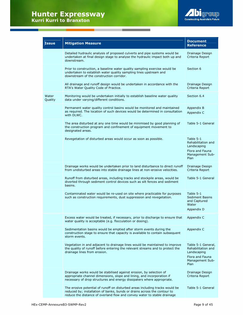
Issue Mitigation Measure Document
Reference
Detailed hydraulic analysis of proposed culverts and pipe systems would be undertaken at final design stage to analyse the hydraulic impact both up and
downstream.
Drainage Design Criteria Report
Prior to construction, a baseline water quality sampling exercise would be undertaken to establish water quality sampling lines upstream and downstream of the construction corridor.
Section 6
All drainage and runoff design would be undertaken in accordance with the RTA’s Water Quality Code of Practice.
Drainage Design Criteria Report
Water
Quality
Monitoring would be undertaken initially to establish baseline water quality
data under varying/different conditions.
Section 6.4
Permanent water quality control basins would be monitored and maintained as required. The location of such devices would be determined in consultation
with DLWC.
Appendix B
Appendix C
The area disturbed at any one time would be minimised by good planning of the construction program and confinement of equipment movement to designated areas.
Table 5-1 General
Revegetation of disturbed areas would occur as soon as possible. Table 5-1 Rehabilitation and Landscaping
Flora and Fauna Management Sub-Plan
Drainage works would be undertaken prior to land disturbance to direct runoff from undisturbed areas into stable drainage lines at non-erosive velocities.
Drainage Design Criteria Report
Runoff from disturbed areas, including tracks and stockpile areas, would be diverted through sediment control devices such as silt fences and sediment
basins.
Table 5-1 General
Contaminated water would be re-used on site where practicable for purposes such as construction requirements, dust suppression and revegetation.
Table 5-1 Sediment Basins and Captured Water
Appendix D
Excess water would be treated, if necessary, prior to discharge to ensure that water quality is acceptable (e.g. flocculation or dosing).
Appendix C
Sedimentation basins would be emptied after storm events during the construction stage to ensure that capacity is available to contain subsequent storm events.
Appendix C
Vegetation in and adjacent to drainage lines would be maintained to improve the quality of runoff before entering the relevant streams and to protect the
drainage lines from erosion.
Table 5-1 General, Rehabilitation and
Landscaping
Flora and Fauna Management Sub-Plan
Drainage works would be stabilised against erosion, by selection of
appropriate channel dimensions, slope and lining, and incorporation if necessary of drop structures and energy dissipaters where appropriate.
Drainage Design
Criteria Report
The erosive potential of runoff on disturbed areas including tracks would be reduced by; installation of banks, bunds or drains across the contour to reduce the distance of overland flow and convey water to stable drainage
Table 5-1 General
Hunter Expressway Kurri Kurri to Branxton
HEx-CEMP-AnnexureB3-SWMP-Rev2 Page 10 of 45
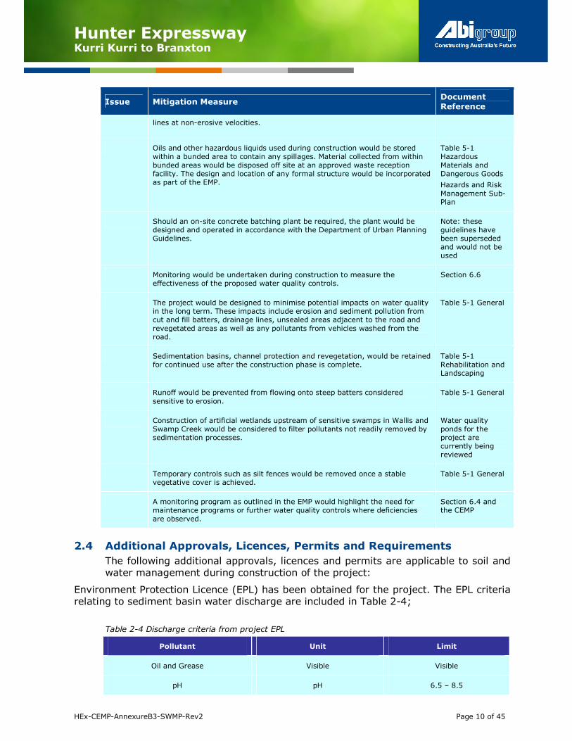
Issue Mitigation Measure Document
Reference
lines at non-erosive velocities.
Oils and other hazardous liquids used during construction would be stored within a bunded area to contain any spillages. Material collected from within
bunded areas would be disposed off site at an approved waste reception facility. The design and location of any formal structure would be incorporated as part of the EMP.
Table 5-1 Hazardous
Materials and Dangerous Goods
Hazards and Risk
Management Sub-Plan
Should an on-site concrete batching plant be required, the plant would be designed and operated in accordance with the Department of Urban Planning Guidelines.
Note: these guidelines have been superseded and would not be used
Monitoring would be undertaken during construction to measure the effectiveness of the proposed water quality controls.
Section 6.6
The project would be designed to minimise potential impacts on water quality in the long term. These impacts include erosion and sediment pollution from cut and fill batters, drainage lines, unsealed areas adjacent to the road and
revegetated areas as well as any pollutants from vehicles washed from the road.
Table 5-1 General
Sedimentation basins, channel protection and revegetation, would be retained for continued use after the construction phase is complete.
Table 5-1 Rehabilitation and Landscaping
Runoff would be prevented from flowing onto steep batters considered
sensitive to erosion.
Table 5-1 General
Construction of artificial wetlands upstream of sensitive swamps in Wallis and Swamp Creek would be considered to filter pollutants not readily removed by sedimentation processes.
Water quality ponds for the project are currently being reviewed
Temporary controls such as silt fences would be removed once a stable vegetative cover is achieved.
Table 5-1 General
A monitoring program as outlined in the EMP would highlight the need for maintenance programs or further water quality controls where deficiencies
are observed.
Section 6.4 and the CEMP
2.4 Additional Approvals, Licences, Permits and Requirements
The following additional approvals, licences and permits are applicable to soil and
water management during construction of the project:
Environment Protection Licence (EPL) has been obtained for the project. The EPL criteria
relating to sediment basin water discharge are included in Table 2-4;
Table 2-4 Discharge criteria from project EPL
Pollutant Unit Limit
Oil and Grease Visible Visible
pH pH 6.5 – 8.5

Hunter Expressway Kurri Kurri to Branxton
HEx-CEMP-AnnexureB3-SWMP-Rev2 Page 11 of 45
Total Suspended Solids mg/L 50
If required groundwater investigation licences will be obtained prior to any groundwater
investigations; and Water Extraction Licences will be obtained prior to any groundwater
extraction.
Cessnock City Council - Development Application Approval 8/2005/295/1. Construction of rail embankment and bridges to accommodate the F3 Motorway
construction underpass. The conditions of consent relevant to soil and water
management are summarised in Table 2-5
Table 2-5 Relevant conditions of consent from DA approval 8/2005/295/1
Condtion Number
Conditions of Consent Document Reference
10
The control of erosion and the prevention of silt discharge into drainage systems and waterways will be necessary in accordance with RTA’s QA Specification G39 “Soil and Water Management”. Erosion control measures are to be implemented prior to commencement of any earthworks and shall be maintained until satisfactory completion and restoration of site earthworks, including revegetation of all exposed areas.
Table 5-1 General, Sediment Basins and Captured
Water, Rehabilitation
and Landscaping.
2.5 Guidelines and Standards
The key reference materials relevant to management of soil and water during design, construction and operation of road projects include:
General Guidelines and Standards:
• Managing Urban Stormwater: Soils and Construction. Landcom, (4th Edition) March 2004 (reprinted 2006) (the “Blue Book”). Volume 1 and Volume 2;
• Volume 2A Installation of Services (DECCW 2008)
• Volume 2C Unsealed Roads (DECCW 2008)
• Volume 2D Main Roads Construction (DECCW 2008);
• DIPNR Roads and Salinity Guideline, 2003;
• Department of Environment and Conservation (DEC): Bunding & Spill
Management. Insert to the Environment Protection Manual for Authorised Officers
- Technical section "Bu" November 1997;
• ANZECC/ARMCANZ - Australian and New Zealand Guidelines for Fresh and Marine Water Quality, October 2000;
• DLWC, 1998. Constructed Wetlands Manual;
• Department of Infrastructure, Planning and natural Resources (DIPNR), 2004.
Guideline for the Preparation of Environmental Management Plans;
• Fairfull, S. and Witheridge, G. (2003) Why do Fish Need to Cross the Road? Fish Passage Requirements for Waterway Crossings. NSW Fisheries, Cronulla, 16 pp;
• NSW Fisheries, November 2003. Fishnote – Policy and Guidelines for Fish Friendly Waterway Crossings (Ref: NSWF – 1181); and
• Acid Sulfate Soil Manual (ASSMAC 1998).

Hunter Expressway Kurri Kurri to Branxton
HEx-CEMP-AnnexureB3-SWMP-Rev2 Page 12 of 45
Client Specifications:
• RTA QA Specification G38 – Soil and Water Management;
• Scope of Works Technical Criteria (Appendix A);
• RTA D&C G36 – Environmental Protection (Management System) (Section 6.5);
• NSW RTA ASS Guidelines [Guidelines for the Management of Acid Sulfate Materials: Acid Sulfate Soils, Acid Sulfate Rock and Monosulfidic Black Ooze, 2005];
• RTA Code of Practice for Water Management – Road Development and Management, April 1999;
• RTA emergency procedures for fuel and oil spillage; and
• RTA, Guideline for Construction Water Quality Monitoring (date unknown).
Hunter Expressway Kurri Kurri to Branxton
HEx-CEMP-AnnexureB3-SWMP-Rev2 Page 13 of 45
3.0 Site Specific Features
3.1 General
The project is located within the Hunter-catchment area. The landform of the
study area consists mainly of a gently undulating landscape. Geological conditions are generally stable sedimentary rocks with some volcanic rocks interspersed.
There are no threatened freshwater fish or invertebrate species, listed on the Fisheries Management Act 1994 (FM Act) or Commonwealth Environment Protection and Biodiversity Conservation Act 1999 (EPBC Act), that are known or
have the potential to inhabit the Hunter Catchment.
There are no known threatened aquatic populations or aquatic Endangered
Ecological Communities (EEC) listed under the FM or EPBC Acts for the Hunter Catchment. It is unlikely that the estuarine and marine threatened species listed
under the FM or EPBC Acts would be affected the project although these species
may enter freshwater and estuarine habitats. The Hunter Expressway D&C section is not within any State Environmental Planning Policy No 14 – Coastal Wetlands
(SEPP 14) designated wetland areas.
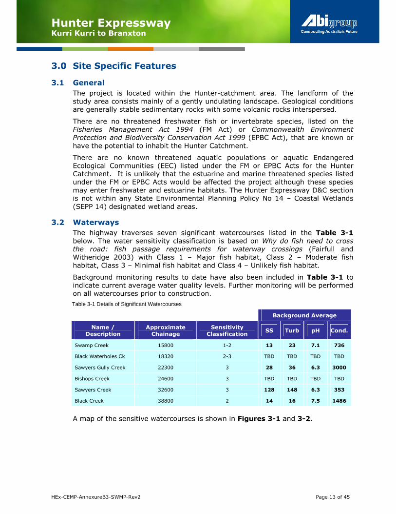
3.2 Waterways
The highway traverses seven significant watercourses listed in the Table 3-1
below. The water sensitivity classification is based on Why do fish need to cross the road: fish passage requirements for waterway crossings (Fairfull and
Witheridge 2003) with Class 1 – Major fish habitat, Class 2 – Moderate fish
habitat, Class 3 – Minimal fish habitat and Class 4 – Unlikely fish habitat.
Background monitoring results to date have also been included in Table 3-1 to indicate current average water quality levels. Further monitoring will be performed
on all watercourses prior to construction.
Table 3-1 Details of Significant Watercourses
Background Average
Name /
Description
Approximate
Chainage
Sensitivity
Classification SS Turb pH Cond.
Swamp Creek 15800 1-2 13 23 7.1 736
Black Waterholes Ck 18320 2-3 TBD TBD TBD TBD
Sawyers Gully Creek 22300 3 28 36 6.3 3000
Bishops Creek 24600 3 TBD TBD TBD TBD
Sawyers Creek 32600 3 128 148 6.3 353
Black Creek 38800 2 14 16 7.5 1486
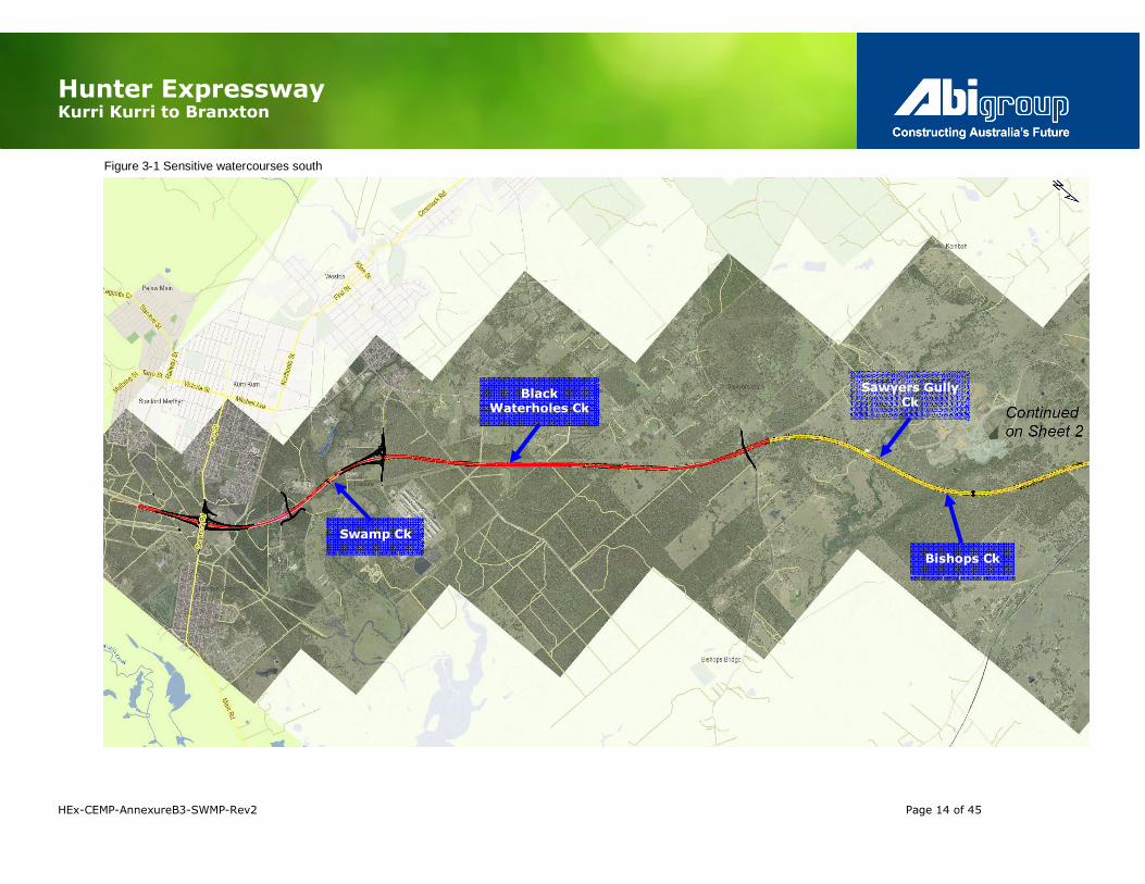
A map of the sensitive watercourses is shown in Figures 3-1 and 3-2.
Hunter Expressway Kurri Kurri to Branxton
HEx-CEMP-AnnexureB3-SWMP-Rev2 Page 14 of 45
Figure 3-1 Sensitive watercourses south
Swamp Ck
Black Waterholes Ck
Sawyers Gully Ck
Bishops Ck

Hunter Expressway Kurri Kurri to Branxton
HEx-CEMP-AnnexureB3-SWMP-Rev2 Page 15 of 45
Figure 3-2 Sensitive watercourses north
Black Ck Sawyers Ck
Anvil Ck
Anvil Ck

Hunter Expressway Kurri Kurri to Branxton
HEx-CEMP-AnnexureB3-SWMP-Rev2 Page 16 of 45
3.3 Landform
The landform along the Hunter expressway route is described in Table 3-2 below.
Table 3-2 Topography
Chainage Landform
Ch 13,400 to 17,500 - Stanford Road to Bishops
Lane
Low rolling hills with broad crests with slopes of 5 per cent to 20 per cent. The Expressway will be crossing Swamp Creek, regrowth farmland, alongside and or
through cleared power easement.
Ch 17,500 to 19,500 - Bishops Lane to Bakers Lane
Gently undulating rises with swamps in the lowlands, with up to three percent slope, landscape regularly cut by drainage line every 500 to 800 metres.
Ch 19,500 to 39,500 - Bakers Lane to the New England Highway
Undulating rises to low hills intersected by creek flats slope between three to five percent
3.4 Geology
Information was gathered from DLWC Soil Landscape Sheets for:
• Newcastle, at a 1:100,000 scale (1995); and
• Singleton, at a 1:250,000 scale (1991).
Due to the broader scale of the Singleton sheet and the lack of detail provided
with the sheets supporting document there is less detail that can be provided for
the western section of the Hunter Expressway route, which includes the majority of Abigroup’s Design & Construct project footprint.
3.5 Soils
The soil types along the highway are described in Table 3-3 below. The soil
information is from the DLWC Soil Landscape Sheets for Newcastle, at a
1:100,000 scale (1995) and Singleton, at a 1:250,000 scale (1991).
Table 3-3 Soil types
Chainage Soil Type Characteristics
Ch 13,400 to 17,500 - Stanford Road to Bishops
Lane
“Bolwarra Heights”
Shallow fine sandy loam (bull dust) topsoil on top of sodic /dispersive clays:
• Medium to high rates of runoff – soil hydrologic grouping C;
• Topsoil (most common) brown fine sandy loam with areas of stoniness (bull dust); classified as Fine, K-factor 0.028;
• Topsoil black fine sandy loam (bull dust) classified as Fine, K-factor 0.035;
• Subsoil yellowish brown clay classified as Fine & Dispersive (in parts); K-factor 0.028; and
• Subsoil Reddish brown mottled clay, classified as Fine; K-factor 0.022.
Potential for wind erosion is low.
Ch 17,500 to
19,500 - Bishops Lane to Bakers Lane
“Neath” Soils: grey sodic soils that poorly drained that are highly erodible from water
flows:
• Medium rates of runoff depending on the depth of the watertable –soil hydrologic group C;

Hunter Expressway Kurri Kurri to Branxton
HEx-CEMP-AnnexureB3-SWMP-Rev2 Page 17 of 45
Chainage Soil Type Characteristics
• When exposed subsoil (gray sandy clay) highly erodible;
• Topsoil brown clayey sand massive structure, classified as Fine, K-factor 0.025;
• Subsoil shallow brown sandy loam massive, classified as fine, K-factor 0.030; and
• Subsoil gray sandy clay with mottles massive structure, classified as
Fine with areas of Dispersive, K-factor 0.025.
Potential: for wind erosion medium with the removal of ground cover.
Ch 19,500 to 39,500 - Bakers Lane to
the New England Highway
“Branxton” Soil: is a Yellow and Red Podzolic soils a sandy loam:
• Low to medium rates of runoff depending on the depth of the watertable and hard setting of the surface in some areas (red soils) –soil hydrologic group B/ C;
• All soils are classified as highly erodible to sheet & concentrated flows;
• Topsoil Brown to reddish fine sandy loam (bull dust) classified as
Cause to Fine; K-factor 0.030; and
• Subsoil mottled light clay ranging from reddish to yellow mottles classified as Fine; K-factor 0.035.
Potential for wind erosion high with the removal of ground cover.
3.6 Rainfall Records
The rainfall records of Cessnock (Nulkaba) have been chosen to reflect the
potential rainfall conditions of the project site due to its proximity to the overall site, and extent of available data (43 years). A summary of the rainfall records from the Bureau of Meteorology is provided in Table 3-4 below.
Table 3-4: Summary of Rainfall Records
Cessnock rainfall records for past 43 years (mm)
Summer - Autumn Winter - Spring
Dec Jan Feb Mar Apr May Jun Jul Aug Sep Oct Nov Year
Mean (rainfall
mm)
70.2 87.3 102.1 87.0 57.0 53.3 57.3 32.0 37.4 43.5 58.4 69.7 754.3mm
Mean
(Rain days)
9.5 10.4 10.4 10.7 8.8 8.7 7.3 7.7 7.6 9.5 10.9 9.5 110.4
days
Summer / autumn period is the dominant rainfall period and is dominated by
easterly trade winds. It should be noted that summer thunderstorms (Southerly Busters) have an important bearing on rainfall intensity in this area.
Winter/spring rainfall generally occurs during late winter and early spring and is less reliable. The summer-autumn has the highest probability for erosion during the thunderstorm season this will be compounded when areas are left bare of
vegetation for prolonged periods.
The 5 day 85th percentile rainfall depth for Cessnock is noted to be 31mm, which
will be used for basin design and management.

Hunter Expressway Kurri Kurri to Branxton
HEx-CEMP-AnnexureB3-SWMP-Rev2 Page 18 of 45
3.7 Rainfall Erosivity Factor
The Rainfall Erosivity Factor is a measure of the ability of rainfall to cause erosion and is used in determining total potential soil runoff, (referred as “R” in the
Revised Universal Soil Loss Equitation RUSLE). The Rainfall Erosivity factor is used
to determine the soil loss in tonnes per hectare over one year, and is used in calculations in relations in sizing sediment basins.
The project has a Rainfall Erosivity factor of 2,000 SI. Newcastle City is the closest location with detailed R-factor data and is detailed below in Table 3-5 below.
Table 3-5: Monthly % and Annual Rainfall Erosivity (R-factor) values for Newcastle City
Monthly % and Annual Rainfall Erosivity (R-factor) values
Dec Jan Feb Mar Apr May Jun Jul Aug Sep Oct Nov Year
% 8.8 9.9 12.9 10.7 8.9 7.9 6.0 4.7 5.1 5.6 5.8 8.8 3890
R-Values 342 385 501 536 416 345 307 233 183 198 218 225 3980
3.8 Groundwater
Groundwater Levels
The groundwater levels along the route are quite variable due to the influence of
the topography, land use, geological structure, soil permeability and porosity, traversing water courses, and man-made influences such as underground coal
mines. Piezometers have been installed predominantly in the cuts along the route.
Generally, the groundwater levels vary between 5 m to 15 m depth below existing surface.
In some locations groundwater levels in cuts will be above the cut floor. Higher
groundwater levels are expected in lower lying areas where fills are to be
constructed and piezometers may not have been installed. In these areas groundwater levels may be expected to be within a few metres from the surface.
In addition, these low lying areas may also be subject to backwater from Hunter
River flooding episodes.
A review of available groundwater level and quality data for the road alignment
indicates that shallow groundwater will potentially be encountered at up to twelve
road cuttings along the project alignment. In half of those instances the road design level is less than a metre below the maximum reported shallow
groundwater level, and the shallow water table is likely to re-equilibrate to the
road level or below once the cutting is established and some of the former
recharge to the water table is captured and redirected by surface drains.
Potential occurrences where the water table could rise above the road grade would
likely relate to storm events. Therefore, these cuttings are only likely to produce
groundwater seepage from cutting faces intermittently.
Seepage has been identified in isolated sections of the proposed route and above
grade level in a few subsurface investigation points within the proposed cuts.
It is anticipated that where spring activity or elevated groundwater levels are present within cut areas, there will be a requirement for one or more of the
following: Surface drainage by lined drains; subsoil drainage employing agricultural drainage trenches; rock-slope drainage holes for control of surface
fretting and improvement in cut-slope stability.

Hunter Expressway Kurri Kurri to Branxton
HEx-CEMP-AnnexureB3-SWMP-Rev2 Page 19 of 45
Where cuttings intersect the groundwater table by more than a metre, a localised fall of the water table due to groundwater drainage of the cutting could potentially
impact groundwater dependent ecosystems (GDEs) in close proximity to the
cutting if present. The locations of potential GDEs were reviewed relative to the cuts that intersect the water table by greater than a metre. The results of this
review indicate that there is a negligible risk based on the distance to potential GDEs from the identified cuttings.
Groundwater Quality
In general groundwater quality within the road alignment can be classified as brackish with an average electrical conductivity (EC) value of 3000 µS/cm. When
compared to the published ANZECC (2000) EC value for lowland rivers of 300 µS/cm which would generally apply to the creeks within the vicinity of the road
alignment, all but one of the reported EC values for groundwater likely to be
encountered at the road cuttings exceed this set criteria. Values for EC were reported as being as high as 5090 µS/cm for one of the creeks along the
alignment (Black Waterholes Creek).
Groundwater pH has been generally recorded as being close to neutral pH with all
but three readings of groundwater pH values falling between 6.0 and 8.0. The other three readings were found in a range of pH 5.0 to pH 5.8 making them
slightly acidic. Approximately one third of groundwater samples taken along the road alignment that have the potential to be encountered in the cuttings had pH values below the ANZECC (2000) lower limit of 6.5 for lowland rivers. pH values
below the pH 6.5 threshold were reported in only one of the creek water samples. During a site visit to the alignment, potential acid mine drainage impact was noted
in Anvil Creek with an orange oxidised iron precipitate coating on the creek bed observed, as well as a pH value of approximately 3.5 recorded along with elevated
levels of sulphate, and an electrical conductivity value of 2200 µS/cm. Therefore,
the potential for baseline creek water quality along the alignment not conforming to the ANZECC water quality guidelines is a possibility.
Local Groundwater Users
A search of the NOW groundwater bore database identified 39 licensed groundwater bores within a 5 km buffer around the proposed road alignment, with
the following license types:
• 19 stock, domestic and irrigation bores;
• 2 NOW monitoring bores; and
• 18 “unknown” bores (the majority of which appear to be monitoring wells installed in the vicinity of the Hydro Aluminium Smelter).
Five of the 39 identified bores are located within 500 m of the road alignment, all
of which appear to be stock and domestic bores associated with a single farm
property between Ch. 20500 and 21000. Given the size of the search area, this is considered to be a sparsely used groundwater resource likely attributable to the
relatively high average EC value of the regional groundwater (approximately 3000
µS/cm), and generally low yields reported for local bores (generally <1 L/s).

Hunter Expressway Kurri Kurri to Branxton
HEx-CEMP-AnnexureB3-SWMP-Rev2 Page 20 of 45
Based on the reported groundwater quality, the potential uses of the resource are generally limited to stock watering and irrigation of salt-tolerant crops.
Mine Void Water
Various surface and subsurface investigations have been conducted to date to
explore the mine workings below the HEX alignment near Greta.
Borehole investigations, SONAR and camera surveys showed that most of the
mine workings are flooded. A total of 13 piezometers were installed for groundwater monitoring. Groundwater was observed to vary from 12m to 14m in
November 2009.
General mine water quality has been assessed for the Greta mine workings by RCA and Douglas Partners and the Heddon Greta mine workings by RCA only. The
quality of mine water has been assessed based on the laboratory test data. In general, water quality indicates some level of impact from pyrite oxidation that is
consistent from the results of logging and testing of the rock cores along the HEX
alignment. General characteristics of the mine water are presented in Table 3-6 below (based on available data):
Table 3-6: Summary of general water quality parameters for mine water
pH Conductivity Iron (total) Sulfate -log[H+] uS/cm mg/L mg/L 3.9-7.2 4900-9070 213 2400
In general, this water quality is characteristic of sulphide mineral oxidation, and is
significantly more saline, and more acidic, than water quality in most of the local
creeks. As such mine water displaced (or pumped) to surface during remediation of the workings would require management to prevent impacts to the surrounding
environment. For the same reason, potential reuse options will also have an overriding requirement to protect the local environment.
Additional mine water quality data was collected in conjunction with the pumping
tests conducted within the mine workings. Whilst this information generally confirmed previous mine water quality results, it also identified the presence of
total petroleum hydrocarbons (TPH), benzene, toluene, ethylbenzene and xylenes
(BTEX). These organic contaminants are not typically associated with the sulphide mineral oxidation processes that typically affect mine water quality. The BTEX
compounds that were detected were present at very low concentrations with all
results below the relevant ANZECC trigger values. The reported TPH
concentrations were reported as a maximum of 24 mg/L, which is close to the solubility limit of the analyte (note: there is no reliable TPH water quality criterion
in Australia).
The source of organic contamination in the mine water is uncertain and was identified within both mine workings at widely spaced wells. There is no obvious
contamination source based upon land use within the immediate vicinity of either
of the pump tests. The two most likely sources include:
• Former underground mining operations - diesel and oil would have been
used extensively in underground equipment, and anecdotal experience from
other mine sites suggests that housekeeping procedures in underground
workings was historically poor; and

Hunter Expressway Kurri Kurri to Branxton
HEx-CEMP-AnnexureB3-SWMP-Rev2 Page 21 of 45
• Hydrocarbon-based thread grease for drill rods – some greases used in the drilling industry are hydrocarbon-based. These greases are specifically
avoided in environmental drilling due to the possibility of false positive TPH detections. It is unknown whether this is relevant for these boreholes, but
could potentially explain the widespread nature of the detections.
Rectification Works and Mine Water Response
The proposed mine rectification process is to inject grout into the mine voids that
are understood to be flooded below 12m to 14m. The mine record tracing (RT) shows that the mine workings are interconnected along the main alignment (Ch
32050-32520). However, geotechnical investigations also show presence of rubble and goaf in some of these mine areas, which may affect the connectivity of the mine voids.
To appreciate the behaviour of mine water in response to grout injection, a pumping out and injection test was conducted in December 2009. The test showed
a linear drawdown of about 0.36m for a period of 48 hours with a pumping-out
rate of 13 l/s. Following cessation, the mine water was allowed to recover for a period of three days and the water recovery was 0.04-0.05m over this period. The
monitoring of six further boreholes showed a similar drawdown and recovery.
The small drawdown and similar response between the pump well and the
observational wells show good connectivity of the mine water. The slow recovery indicates limited groundwater recharge from the surrounding rock formations. The
results of the test suggest that given the limited volume of the workings to be impacted by the grout infilling process, a substantial change in water level is not likely.
Measures to manage mine void water and mine stabilisation works are described in Table 5-1.
3.9 Acid Sulfate Soils and Rock
Generally ASS will occur in low lying regions of the project <10m AHD (such as
back swamps, floodplain and estuaries) and are characterised by grey to green-
blue soft soils, sulphurous odours after rain, presence of shell and yellow/straw coloured jarosite in upper soils and associated water indicators such as iron floc
and clear milky water associated with acidification. ASR occurrence may occur in geology comprising sulphidic ores and uplifted ASS over geological timeframes.
This type of rock may be intercepted and disturbed where deep cuttings and
excavations occur.
Details of occurrence and management and mitigation measure regarding
disturbance of acid sulfate soils (ASS) and acid sulfate soil rock (ASR) are
presented in the Acid Sulfate Soil Strategy (Appendix F).
3.10 Contaminated Land/Soil
There are several potentially contaminated sites along the project including old mine working and the old Branxton Rail Siding. Details of potential for
encountering contaminated materials during project works are discussed in the Hazard and Risk Management Sub-Plan (Annexure B8).
The Contaminated Land Protocol in the Hazard and Risk Management Plan
(Annexure B8 Appendix B) details the procedure to be followed to identify and
manage contaminated soil.

Hunter Expressway Kurri Kurri to Branxton
HEx-CEMP-AnnexureB3-SWMP-Rev2 Page 22 of 45
3.11 Afflux and Flood Management
Hydraulic modelling has been carried out to size brides and culverts to ensure compliance with SWTC design requirements and to assess flooding risk and afflux
impacts.
The Rainfall IFD (Intensity Frequency Duration) data used in the modelling was obtained from the Bureau of Meteorology (BoM) website selecting a location near
Allandale Interchange.
The hydrology for the transverse drainage was determined using two methods. For catchments of les than 50 hectares the Probabilistic Rational Method was
used, for catchments greater than 50 hectares the hydrological stormwater routing package RAFTS was used.
Catchment areas were defined using a combination of land survey information
within the road corridor, detailed photogrammetry over an area extending approximately 500m either side of the road corridor and 10m contour information
from the CMA topographical maps for the remaining area.
Culverts have been sized to ensure existing flow distributions are generally
maintained, affluxes are within acceptable limits and the Highway has the required 100 year ARI flood immunity. Water levels in the culverts are calculated
using the in house culvert design program CDMD (Cross Drainage Management
Database) that uses the methodology and formula used in HEC-RAS.
Consideration has been given to the consequences of culvert blockage in larger
culverts in relation to flooding of the main alignment and impact on upstream
properties. Where it was considered the consequence of 50% culvert blockage could result in damage or extended flooding of the highway or damage to
adjoining property improvements, measures were included to reduce blockage
risk or increase the culvert size to ensure acceptable performance under a 50%
blockage scenario.
The design includes three bridged waterway crossings; Swamp Creek (Chainage
15800), Anvil Creek (Chainage 35200) and Black Creek (Chainage 38800). Bridge
crossings were assessed using the hydraulic modelling software (HEC-RAS). Models were developed to represent the existing case and proposed design case.
When considering afflux impacts, it was noted that site visits and recent aerial photographs show there are no buildings in the immediate vicinity of any of the
bridged waterway crossings.
Final afflux calculations will be completed as part of detailed design and assessed against an acceptability criteria. This criteria is detailed further in the Drainage
Design Report and assesses afflux impacts against the sensitivities of receiving
environments to guide management measures to be implemented.
The afflux acceptability criteria will be applied to the afflux results and upstream and downstream mitigation recommended where required. The outcome of any required additional mitigation measures will be included in the SWMP where
applicable following completion of detailed design.
If in any circumstances the actual afflux is determined to be outside the proposed
acceptability criteria, a number of options will be assessed to minimise afflux
including:
• Further detailed modelling of the impacted areas;

Hunter Expressway Kurri Kurri to Branxton
HEx-CEMP-AnnexureB3-SWMP-Rev2 Page 23 of 45
• Additional survey of affected areas;
• Review of culvert and bridges sizes;
• Review of inlet and outlet treatments; and
• Detailed assessment and consultation with affected property owners.
Detailed design has also assessed the regional impact of the loss of flood storage
area from floodplain. The Swamp Creek Bridge and Branxton Interchange crossing at Anvil Creek were assessed to not be removing any significant volume of Hunter
River flood storage.
The project embankment that will be constructed on the Black Creek Floodplain
will result in the loss of approximately 245,300 m3 of Hunter River flood storage. However, by way of comparison, the estimated discharge over the duration of a Hunter River flood is in the order of 1,300 x 106 m3.
Accordingly, the loss of flood storage and the associated flood impact is negligible in the context of the volume of the flood discharge.
3.12 Operational Stormwater and Water Quality Management
Operation of the Hunter Expressway project has the potential to affect existing
local water quality due to the generation of additional pollutants from the project and associated vehicle traffic. The most important pollutants of concern relating
to road runoff are:
• sediments from the paved surface
• heavy metals attached to particles washed off the paved surface
• oil and grease and other hydrocarbon products
• anthropogenic litter.
In addition, elevated levels of nutrients such as nitrogen and phosphorus are also
found in road runoff from atmospheric deposition of sediment on the road
pavement. As pollutants such as nutrients, heavy metals and hydrocarbons are
usually attached to fine sediments, trapping suspended solids is the primary focus of the water quality management strategy for the operational stages of the
Hunter Expressway project.
The project operational mean annual pollutant target reduction rates are:
• total suspended solids (TSS) – 85%
• total phosphorus (TP) – 65%
• total nitrogen (TN) – 45%.
Accidental chemical spill onto the road surface are also of concern. Spill
management measures are included in the operational water quality measures design to prevent spilt materials passing through the drainage system and
impacting downstream ecosystems. As such methods to retain a minimum 20,000
litres of polluted run-off have been included in the design of sediment basins in
areas where the discharge point is in close proximity to environmentally sensitive creeks

Hunter Expressway Kurri Kurri to Branxton
HEx-CEMP-AnnexureB3-SWMP-Rev2 Page 24 of 45
To achieve the above water quality objectives, measures have been incorporated into the drainage design to direct pavement runoff to pass through one or more of
the following water quality control measure before entering receiving waters.
Permanent Water Quality Ponds
Water quality basins have been designed to trap sediments and associated
contaminants before stormwater is discharged into the receiving waterways. The basins treat road pavement and batter runoff collected by the pavement drainage
network. They operate by reducing flow velocities and promoting the settlement of suspended sediment contained in stormwater runoff.
Measures are also incorporated into the design of all water quality basins to enable the containment of accidental spills of materials that have a density lower than water, such as petroleum hydrocarbons (see spill containment basins
below).
The majority of permanent water quality basins will be converted from
construction phase temporary sediment basins. The locations of basins have
considered site constraints such as the project boundary, EEC vegetation, existing and proposed utilities, environmental and heritage exclusion zones.
Details of the numbers and locations of basins to be used for construction and/or
operational purposes is provided in Appendix G.
The ongoing maintenance of operational water quality basins will be undertaken by the RTA as part of standard practices and procedures for managing operational
basins.
Vegetated Swales Vegetated swales/table drains are used to convey stormwater to the receiving
waterways and provide for some removal of suspended solids and associated pollutants. Pollutant removal is achieved by the vegetation spreading out and
slowing down the stormwater flow aiding the deposition of sediment. Vegetated swales as a treatment measure are proposed at locations where pavement runoff
is not being treated by a water quality basin, and where the grade of the table
drain and the design flow velocity are within acceptable limits.
Vegetation as a table drain lining can be applied where the grade of the table
drain is between 0.5% and 5% and the design flow velocity is less than 1.7m/s.
A typical vegetated swale will have a base width of 1 to 1.5m, a depth of 0.5m, and batter slopes of 1:4 (V:H). Node check dams (RCDs) provided along the
swales at intervals of 20 to 40 m at a height of approximately 0.3m provide significant water quality benefits. These RCDs need to be designed so that flow
capacities are not affected. Vegetated swales with RCDs will be used where
possible at locations where additional water quality treatment is required.

Hunter Expressway Kurri Kurri to Branxton
HEx-CEMP-AnnexureB3-SWMP-Rev2 Page 25 of 45
Spill Containment Basins
The spill containment basins which have an approximate total volume of 60m3
are designed to capture up to 20,000L of a spilt liquid that is less dense water. The spill basins are designed to contain spills in dry weather or light rainfall
events only. Containment is achieved via a reverse graded ‘Ellis’ pipe
arrangement, which due to it’s limited capacity during times of heavy rainfall spills floating on the basin would flow over the spillway rather than via the Ellis
pipe. Underflow baffle devices will be fitted to the spill basins to limit spilt material overflows during wet weather. Contained spilt material will be pumped
out and disposed of in an appropriate manner.
The SWTC (Appendix 14), section 14.2.3(b) requires that spill basins be provided at the following locations unless a water quality basin is already provided:
Swamp, Black, Anvil and Bishop Creeks, the two rest areas and at Kurri, Loxford, Allandale and Branxton Interchanges.
3.13 Construction Phase Stormwater Basins
A number of temporary sediment basins are proposed for the construction phase
of the project (Appendix G). The basins have been designed to meet Blue Book requirements however site constraints limit the available footprint of some basins
resulting in design volumes not meeting the Blue Book requirement. For these
locations the sediment basin sub catchments will require enhanced erosion and sediment controls.
Where possible, the design of sediment basins will be amended to maximise the
available volume. Potential amendments include increasing the basin depth, steepening the internal batter slopes, or decreasing the crest width for temporary
only basins. Where design volumes are less than required volumes by more than
10%, enhanced erosion and sediment controls will be required in the disturbed
sub catchment. Enhanced controls will include additional sediment basins (if space is available), sediment traps, check dams in dirty run-off drains, and additional
sediment fences.

Hunter Expressway Kurri Kurri to Branxton
HEx-CEMP-AnnexureB3-SWMP-Rev2 Page 26 of 45
4.0 Environmental Aspects, Impacts and Risks
4.1 Environmental Aspects
The environmental aspects are activities related to the construction of the project
that may result in an environmental impact. The relationship of aspects and impacts is one of cause and effect and has been assessed further in the risk
assessment undertaken for the project and detailed further in Section 4.3.
The key aspects of the Project that could result in adverse impacts on soil and water include:
• vegetation clearing;
• topsoil stripping;
• bulk earthworks;
• drainage works;
• chemical storage and handling;
• bridge construction;
• shallow ground disturbance (including mine void stabilisation and handling
of void water and rock face cuts);
• excavation stockpiling and reuse of acid sulfate soils and rocks;
• construction of drains and re-alignment of creek beds;
• paving activities;
• water use / extraction;
• construction compounds including fuel and chemical storage areas and re-fuelling; and
• operation of batch plant.
• pesticide spraying
• flooding
• cuts and excavation
4.2 Environmental Impacts
The potential key soil and water impacts that may occur during construction include:
• erosion and transport of extensive amounts of sediment due to the loss of
vegetative cover and the exposure of soil to erosion;
• contamination of soil or water by disturbance of contaminated lands;
• altered flow or drainage patterns;
• generation of additional pollutants directly attributable to road construction
(e.g. heavy metals, oils and greases, petroleum hydrocarbons);
• disturbance of potential acid sulfate soils with the potential for the
generation of potential acidic surface, ground or drainage waters;
• impacts on aquatic organisms and sensitive areas.
• lowering of groundwater levels with potential for associated soil settlement.

Hunter Expressway Kurri Kurri to Branxton
HEx-CEMP-AnnexureB3-SWMP-Rev2 Page 27 of 45
4.3 Environmental Risk Assessment
A risk assessment was undertaken using the risk assessment matrix in Table 4-1 to identify the level of risk that each of the above activities may present. The
results of the soil and water related risk assessment are summarised for each
proposed activity in Table 4-2.
Aspects identified as having higher risk may be downgraded if appropriate controls
and measures are put in place and maintained.
Table 4-1: Risk Assessment Matrix
Consequences
Likelihood 1
Insignificant
2
Minor
3
Moderate
4
Major
5
Severe
A
(Almost
Certain)
Medium Significant High High Extreme
B
(Likely) Medium Medium Significant High Extreme
C
(Moderate) Low Medium Significant High High
D
(Unlikely) Low Low Medium Significant High
E
(Rare) Low Low Low Medium Significant
Table 4-2: Soil and Water Risk Assessment
Section C
Risk Analysis
Section A
Aspect
Section B
Potential Impact
Low
Mediu
m
Sig
nificant
Hig
h
Extrem
e
Soil disturbance resulting in erosion of soil layers X
Erosion and sedimentation of disturbed areas X
Carriage of nutrients to waterways causing algal growth
and eutrophication X
Vegetation clearing
Carriage of weed material to waterways causing weed infestation
X
Erosion of soil horizons that are exposed as a result of
topsoil stripping X
Erosion and sedimentation of stockpiles X
Topsoil
stripping
Pollution caused by stockpiles erosion X
Erosion of disturbed areas X Bulk earthworks
Sedimentation of local waterways X

Hunter Expressway Kurri Kurri to Branxton
HEx-CEMP-AnnexureB3-SWMP-Rev2 Page 28 of 45
Section C
Risk Analysis
Section A
Aspect
Section B
Potential Impact
Low
Mediu
m
Sig
nificant
Hig
h
Extrem
e
Increase velocity of water flow causing scouring X
Localised flooding due to sedimentation X
Sedimentation causing blockage of water flow and fish passage
X
Sedimentation causing reduced visual value of natural features
X
Sedimentation causing damage to existing drainage infrastructure
X
Altered groundwater quality and quantity X
Exposure of contaminated soil X
Disturbance of PASS X
Increased flow or more concentrated flows causing scouring
X
Pollution of downstream environments X
Drainage works
Direct impacts on streambeds through excavation works X
Damage to riparian vegetation causing instability of stream
banks X
Pollution arising from accidental spillage of materials X
Erosion of riverbed X
Bridge
construction
Damage to aquatic habitat X
Exposure of unexpected contaminated soil and/or groundwater
X
Exposure to construction workers X
Release of contaminated materials into the surrounding environment
X
Ground disturbance of unexpected contamination
Long term impacts on local ecosystems X
Shallow ground disturbance
Exposing ASS at the disturbed areas to surface run--off, thus causing the release of acid into the environment in the short term
X
Changing surface run-off behaviour and subsequently acid releases into the environment in the short and long term.
X
Exposing ASS to surface run-off, thus causing the release of acid into the environment in the short and long term
X
Exposing PASS to air and surface run-off, thus causing
increased oxidisation and increased release of acidity into the environment in the short to long term
X
Changing surface run-off behaviour and subsequently acid releases into the environment in the short and long term
X
Discharge of high pH water at the disposal site X
Wind dispersal of stockpiled liming agents X
Excavation
stockpiling and reuse of ASS and ASSR in
“Dry Areas” (opposed to creek beds or drains)
Leaching acid into the environment at the disposal site X
Exposing ASS at/near new alignment to surface run-off
and drain, creek flow, thus causing the release of acid into the environment in the short and long term
X Construction of
drains and re-alignment of creek beds
Exposing PASS along the new alignments to air, surface run-off and water flows, thus causing increased oxidisation and increased release of acidity into the environment in the short to long term
X

Hunter Expressway Kurri Kurri to Branxton
HEx-CEMP-AnnexureB3-SWMP-Rev2 Page 29 of 45
Section C
Risk Analysis
Section A
Aspect
Section B
Potential Impact
Low
Mediu
m
Sig
nificant
Hig
h
Extrem
e
Changing surface run-off behaviour and subsequently acid releases into the environment in the short and long term
X
Leaching of high pH water into the environment X
Leaching acid into the environment at the stockpile site X
Acidic leachate may be brought to the surface for a period of approximately 3-6 months
X
Application of excessive liming agent and release of high pH water; and
X
Embankment
treatment: collection of acid leachate from wick drains Discharge of acid leachate to land or receiving waters X
Run-off of chemicals eg curing compounds X Paving
Increased surface run-off from hard surfaces causing erosion and sedimentation
X
Pollution of local waterways from accidental spillage or inappropriate storage
X
Ground contamination (as above) X
Compounds
including fuel
and chemical storage areas
Damage to ecosystems, aquatic species due to pollution of local waterways
X
Pollution of local waterways arising from accidental spillage, washouts or equipment malfunction
X Batch plant operation
Harm to aquatic ecosystems X
4.4 Summary of potential sources of water pollution
Based on the soil and water risk assessment, Table 4-3 contains list of the
potential sources of water pollution:
Table 4-3: Potential sources of water pollution
Potential Pollution Sources Activity Reference to mitigation measures
Sediment / Turbidity • Drainage works and creek realignments
• Operation of construction compounds and batching plants
• Vegetation clearance
• Soil stripping and stockpiling • Bulk earthworks
• Geotechnical investigations / drilling
Table 5-1:
• General
• Sediment Basins and Captured Water
• Drainage and Waterway Crossings
• Rehabilitation and Landscaping
• Monitoring inspections and reporting
Hydrocarbons • Geotechnical investigations / drilling
• Operation of construction compounds and batching plants
• Refuelling
Table 5-1:
• Hazardous Materials and Dangerous Goods
• Hazard and Risk Management Plan

Hunter Expressway Kurri Kurri to Branxton
HEx-CEMP-AnnexureB3-SWMP-Rev2 Page 30 of 45
Potential Pollution Sources Activity Reference to mitigation measures
Mine void water • Geotechnical investigations / drilling
• Mine Void Stabilisation
Table 5-1:
• Mine Void Water and mine stabilisation
Concrete Slurries / wash
water
• Operation of construction compounds and batching plants
• Mine Void Rectification
• Bridge Construction
• Paving
Table 5-1:
• Wastewater
• Mine Void Water and mine stabilisation
Acid Sulphate Soils • Drainage works and creek realignments
• Soil stripping and stockpiling
• Bulk earthworks
Table 5-1:
• Contaminated Land and Acid Sulphate Soils
Contaminated Soils • Drainage works and creek realignments
• Soil stripping and stockpiling
• Bulk earthworks
Table 5-1:
• Contaminated Land and Acid Sulphate Soils
• Hazard and Risk Management Plan

Hunter Expressway Kurri Kurri to Branxton
HEx-CEMP-AnnexureB3-SWMP-Rev2 Page 31 of 45
5.0 Environmental Control Measures
The following controls in Table 5-1 will be implemented to minimise potential soil and water impacts.
Table 5-1: Environmental Control Measures
Mitigation Measures
Desig
n
Pre-
Construction
Construction
Reference Documents or Source of Commitment
(if applicable)
Responsibility
General
SW 1 A primary project specific ESCP will be developed and finalised prior
the commencement of construction � �
Managing Urban Stormwater: Soils and
Construction, Volume 2D, Main Road Construction (DECC 2008).
Soil Conservationist
SW 2 All personnel will undertake a site induction on environmental awareness (soil and water related) including their responsibilities under the management plan.
� � Good Practice Environment Manager
SW 3 Ongoing toolbox talks will be delivered to relevant personnel and will
detail issues arising from inspections and proactive measures to minimise impacts on soils and water quality.
� � Good practice Foremen / Environment Officer
SW 4
Specific ERSED training will be provided to relevant site personnel with
responsibilities for planning, installing and maintaining ERSED controls.
� � Good practice Environmental Manager
SW 5 Progressive erosion and sediment control plans (ESCPs) will be
prepared and implemented in advance of construction, including earthworks and stockpiling. ESCPs and will be updated as required.
� �
Managing Urban Stormwater: Soils and Construction Volume 1 (Landcom 2006).
Managing Urban Stormwater: Soils and Construction, Volume 2D, Main Road Construction (DECC 2008).
Environment Manager /
Environment Officer /
Site Engineers
SW 6 Soil and water quality mitigation measures from this sub plan will be included in relevant activity or area specific Work Method Statements (WMSs)
� � Good Practice Environmental Officer
SW 7 A soil conservationist will be engaged and regularly consulted
throughout construction to provide advice on erosion and sediment control design, installation and maintenance
� � � MCoA 90
Good Practice Environmental Manager
SW 8
Clearing of vegetation will be progressive, to minimise exposure of
disturbed land. Clearing will be limited to the minimum necessary to safely design and construct the project.
� � � Good Practice
Design Manager /
Superintendent / Foremen
SW 9 Drainage works to be stabilised against erosion by appropriate
selection of channel dimensions, slope and lining, and the inclusion, if � � Good Practice Design Manager /
Superintendent /

Hunter Expressway Kurri Kurri to Branxton
HEx-CEMP-AnnexureB3-SWMP-Rev2 Page 32 of 45
Mitigation Measures
Desig
n
Pre-
Construction
Construction
Reference Documents or Source of Commitment
(if applicable)
Responsibility
necessary, of drop structures and energy dissipaters. Foremen
SW 10 Run-off to be collected from disturbed areas, including tracks and
stockpile areas, and directed through sediment control devices such as settlement basins or silt fences.
� � Good Practice Design Manager /
Superintendent / Foremen
SW 11
Wheels of vehicles leaving the project site will be clean in order to minimise mud tracking onto public roads. Measures such as rumble
grids, stabilisation of roads with aggregate etc will be used where appropriate.
� � Good Practice Foremen / All / Engineers
SW 12 Vehicle movements from site will be minimised during wet weather if the tracking of mud may become an issue
� Good Practice Foremen /
Superintendent / Environmental Officer
SW 13 Sediment tracked onto public roads from the construction site will be removed by sweeper trucks, brooms or other equipment
� Good Practice Foremen / Superintendent
SW 14 Relevant licences will be obtained prior to the interception, extraction
or utilisation of water sources from groundwater, mine voids, waterways or nearby STPs
� � Legislative Requirements Environmental Manager / Environmental Officer
SW 15 Erosion and sediment control structures will remain installed and
maintained until stable vegetative cover is achieved � Good Practice
Foremen /
Superintendent / Environmental Officer
SW 16
Potential erosion and sediment controls as detailed in Table 5-2 may be applied where appropriate and in consultation with the Project Soil Conservationist.
� � Good Practice
Environment Manager /
Environment Officer / Soil Conservationist
SW 17
Minor temporary storages of spoil associated with waterway works
may be located within 20m of the waterway with implementation of appropriate control measures developed in consultation with the soil conservationist.
� � Good Practice Engineers / Foremen /
Environmental Officer
Sediment Basins and Captured Water
SW 18 Sediment basin(s) will be designed and constructed to handle a 5 day, 85th percentile rain event.
� � �
Managing Urban Stormwater: Soils and
Construction Volume 1 (Landcom 2004).
Good Practice
Design Manager /
Environment Manager/ Superintendent

Hunter Expressway Kurri Kurri to Branxton
HEx-CEMP-AnnexureB3-SWMP-Rev2 Page 33 of 45
Mitigation Measures
Desig
n
Pre-
Construction
Construction
Reference Documents or Source of Commitment
(if applicable)
Responsibility
SW 19
Sediment basin(s) will be designed, operated and maintained in
accordance with Landcom’s guideline Managing Urban Stormwater - Soils and Construction Volume 1 and DECCW’s Main Road Construction Volume 2D.
� � � Managing Urban Stormwater: Soils and
Construction, Volume 2D, Main Road Construction (DECC 2008).
Foremen /
Environmental Officer
SW 20
All required sediment basins and associated drainage will be installed
and commissioned prior to the commencement of clearing and grubbing works in that catchment that could cause sediment to leave site. (Except where clearing is required for basin installation)
� � � EPL Project Manager/ Construction Manager
SW 21
Trials of flocculent stations to add flocculent to water entering basins will be undertaken in consultation with DECCW, RTA and the EMR, and if successful, utilised where feasible on site
� � SWTC Design Manager / Environment Manager/
SW 22
The sediment storage capacity of all sediment basins will be monitored
and maintained as described in the project Sediment Basin Management Guideline (Appendix C).
�
Managing Urban Stormwater: Soils and Construction Volume 1 (Landcom 2004).
Managing Urban Stormwater: Soils and Construction, Volume 2D, Main Road Construction (DECC 2008).
Environment Manager/ Environment Officer
SW 23 Water captured in sediment basins and other areas will be reused for
dust suppression, compaction, etc in preference to potable water. � Good Practice Environment Manager
SW 24 All sediment basin discharge points will be clearly identified and
access made available at all times for inspections or management. � � EPL
Foremen / Engineers /
Environmental Officer
SW 25 Water captured in areas other than sediment basins will be managed in accordance with the guideline described in Appendix D.
� Good Practice Foremen / Environmental Officer
SW 26 Discharge of all captured water will only be undertaken following approval from Environmental Staff.
� Good Practice Environment Manager/ Environment Officer
SW 27 Sediment basin discharge will be managed as detailed in Appendix C – Sediment Basin Management Guideline.
� Good Practice Foremen / All / Environmental Officer
SW 28 Records of discharge will be completed and kept when treated water is to be discharged from the basin as described in Appendix C.
� Good Practice Environment Officer
SW 29
Sediment basins will be retained for a minimum of six months or until a 70% vegetative cover is achieved in its catchment; other satisfactory controls are in place and approved by the EM or the basin is otherwise redundant.
� Good practice Foremen / Environmental Officer
SW 30 The requirements of the project EPL to notify DECCW prior to and � EPL Environmental Manager

Hunter Expressway Kurri Kurri to Branxton
HEx-CEMP-AnnexureB3-SWMP-Rev2 Page 34 of 45
Mitigation Measures
Desig
n
Pre-
Construction
Construction
Reference Documents or Source of Commitment
(if applicable)
Responsibility
before basin installation or deletion will be complied with. / Environmental Officer
Drainage and Waterway Crossings
SW 31
Transverse drainage and clean water diversions will be appropriately sized, designed and constructed prior to the commencement of earthworks to allow the free passage of clean stormwater through the project site.
� � Soils and Construction, Volume 2d Design Manager / Foremen
SW 32
Temporary water crossings:
• will not be used in Class 1 waterways without approval of all relevant authorities
• crossings for Class 2 or Class 3 waterways will be constructed using concrete box culvert cells, or for all other waterways, pipes or culverts sized appropriately for the rainfall and run-off for the area, the catchment size and intended duration of the crossing remaining in place.
• will be installed prior to any disturbance to the waterway
• will be regularly maintained to remove fines and other loose material deposited by construction traffic
• will be partially or completely removed prior to forecast high flow/flood events to prevent the washing of sediment and rock downstream; and
• will be removed with minimal disturbance to the waterway
� � � SWTC 14.6.1 Design Manager /
Engineers / Foremen / Environmental Officer
SW 33
(a) Working platforms must not be used in waterways unless approved by all relevant Authorities. Waterway working platforms constructed from rock must:
• be constructed from rock materials which do not contain any fine materials;
• be designed to prevent small rock or fine capping materials from being washed out of the platform;
• be designed to prevent overtopping of the platform below the 1 in 6 month average recurrence interval event and to prevent scour of the waterway during this event;
• be wrapped in geotextile materials;
• remain in the waterway for the minimum time possible;
• include large rock armouring on all the external faces;
� � � SWTC 14.6.2 Design Manager /
Engineers / Foremen / Environmental Officer

Hunter Expressway Kurri Kurri to Branxton
HEx-CEMP-AnnexureB3-SWMP-Rev2 Page 35 of 45
Mitigation Measures
Desig
n
Pre-
Construction
Construction
Reference Documents or Source of Commitment
(if applicable)
Responsibility
• be protected by anti-pollution booms; and
• include appropriate water flow and/or fish passage treatments.
SW 34 Scour protection will be installed for all waterway crossings to minimise erosion and sediment loss at the crossing.
� � � Good Practice Design Manager / Foremen / Environmental Officer
SW 35
Temporary stockpiles of materials or machinery will not be stored in
drainage lines, without appropriate controls in place to mitigate potential impacts.
� � Good Practice Foremen / Superintendent
SW 36
All bridges, waterway crossings, platforms in waterways and culverts potentially impacting on waterways will be designed and constructed in consultation with I&I NSW (Fisheries).
� � MCoA 68 Design Manager / Environment Manager
SW 37
No earthen platforms will be constructed or fill material placed in
creeks unless prior approval is granted by I&I NSW (Fisheries) and the Director-General.
MCoA 69 Design Manager /
Environment Manager
Wastewater
SW 38
Captured wastewater will be assessed for contamination, tested and
treated if required, and where possible reused on site. Before being released off site or to a waterway captured wastewater will be tested in accordance with Appendix D.
� Good Practice
MCoA91 Environment Officer
SW 39 Concrete washout areas and pits will be adequately sized, located away from drainage lines and maintained regularly.
� � Good Practice Design Manager /
Environment Manager / Superintendent
SW 40
Effluent from site amenities will be designed, licensed if applicable and
managed to minimise off site nutrient, e-coli or other potential impacts.
� � � Good Practice
RTA Guidance Note
Environmental Manager / Superintendent
Groundwater
SW 41 If groundwater is encountered in cuttings or excavations, the process described in Section 6 of this sub plan will be implemented
� Good Practice Foremen / Engineers / Environmental Officer
SW 42
A minimum of four groundwater monitoring bores will be established
along the alignment, with preference given to using existing bores with pr- construction monitoring data. Monitoring of groundwater levels will be carried out at three monthly intervals.
� � MCoA 96 Environment Manager/ Engineers

Hunter Expressway Kurri Kurri to Branxton
HEx-CEMP-AnnexureB3-SWMP-Rev2 Page 36 of 45
Mitigation Measures
Desig
n
Pre-
Construction
Construction
Reference Documents or Source of Commitment
(if applicable)
Responsibility
SW 43
If groundwater is required for construction purposes, a hydrogeologist
will be engaged to assist with conducting investigations, obtaining appropriate licences and monitoring extraction rates and associated impacts.
� � Good Practice Environment Manager/
Engineers
Hazardous Materials and Dangerous Goods
SW 44 Storage and handling of all chemicals will be undertaken in accordance
with the project Hazard and Risk Management Plan (HRMP). � � Project HRMP
Superintendent /
Foremen
SW 45 Appropriately stocked spill kits will be readily available at all chemical storage locations and during chemical use.
� �
Environmental compliance report: Liquid
chemical storage, handling and spill management – Part B Review of best practice and regulation (DECC 2005).
Environment Officer / Foremen
Contaminated Land and Acid Sulfate Soils
SW 46 If suspected ASS is encountered during construction, works with the
potential to affect the ASS will be stopped and the ASS Strategy (Appendix F to this SWMP) will be complied with.
� ASS Strategy
Good Practice
Foremen /
Superintendent / Environment Manager
SW 47
If suspected contaminated materials are encountered during construction, works with the potential to affect the contamination will be stopped and the requirement of the Contaminated Land Protocol (Hazard and Risk Management Plan (HRMP - Appendix B) and the Spoil and Fill Management Sub Plan (SFMP) will be complied with.
�
Good Practice
HRMP _ Contaminated Land Protocol
SFMP – Contaminated Land Guideline
Foremen / Superintendent / Environment Manager
SW 48
All water collected during construction which is likely to be
contaminated, will be tested, treated, handled and disposed of so that it does not pollute waters.
� Good Practice
Foremen /
Superintendent / Environment Manager
Rehabilitation and Landscaping
SW 49
Stabilisation of exposed surfaces will be undertaken as soon as
practicable, progressively and works staged where possible to minimise the amount and time of exposure.
� Good Practice Foremen / Environmental Officer
SW 50
Vegetative species and landscaping techniques would be undertaken
to stabilise disturbed areas in accordance with the project Landscape Management Sub Plan (LSP).
� Good Practice
LSP
Environment Manager/
Engineers / Landscaping Contractor
SW 51
All damage arising from construction activities in the riparian zone will be repaired as soon as practicable.
� Best Practice Environment Manager/ Engineers

Hunter Expressway Kurri Kurri to Branxton
HEx-CEMP-AnnexureB3-SWMP-Rev2 Page 37 of 45
Mitigation Measures
Desig
n
Pre-
Construction
Construction
Reference Documents or Source of Commitment
(if applicable)
Responsibility
Monitoring, Inspections and Reporting
SW 52
Weekly environmental inspections as described in the CEMP will be
undertaken to check the effectiveness of mitigation measures relating to soil and water management.
� Good Practice Environment Manager / Environment Officer
SW53
Inspection of erosion and sediment control measures will be
undertaken daily during rainfall during construction periods and within
24 hours of the cessation of a rainfall event causing runoff to occur from the premises.
� EPL Environment Manager/
Environment Officer
SW 54
Results will be kept for all discharge of captured water and non-
compliance reported to DECCW through regular reporting required by the project EPL.
� EPL Environment Manager/ Environment Officer
SW 55
Monitoring of rainfall at the premises will be undertaken daily to determine compliance with EPL conditions relating to sediment basin sizing and management. Records will be kept to demonstrate compliance and rectification of controls and reported to DECCW monthly as required by the EPL.
� EPL Environment Officer
SW 56
Upstream and downstream monitoring of water quality from
surrounding waterways will be undertaken prior to and during construction to determine impacts from the project, as described in
Section 6.4. Where upstream and downstream levels differ by greater than 10%, an investigation will be undertaken by the Environmental Officer and results reported in monthly reports to DECCW.
� � Good Practice Environmental Officer
SW 57 All instrumentation used for water quality monitoring on site will be calibrated as per the manufacturers specifications
� Good Practice Environmental Officer
Mine Void Water and mine stabilisation
SW 58
Mine void water will only be extracted for use in mine void grout
production. The mine void water will be pumped to the grout batch plant via a holding tank, and then pumped directly back into the void for stabilisation works.
� Good Practice
Foremen / Engineers
SW 59 There will be no discharge of mine void water or grout onto the ground or into waterways.
� Good Practice
POEO Act
Foremen / Engineers/ Environment Officer
SW 60
Any mine void water extracted that is not able to be reused for grout production will be pumped back into adjacent and hydraulically linked mine voids
� Good Practice
MCoA 96 Foremen / Engineers
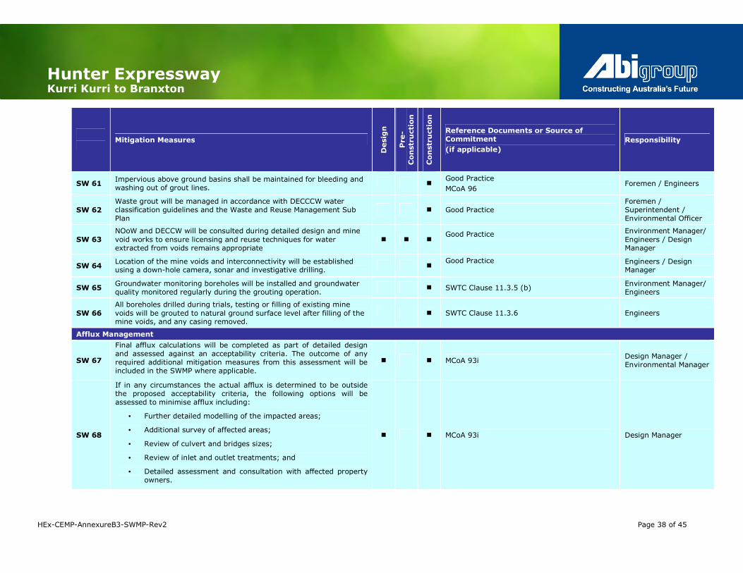
Hunter Expressway Kurri Kurri to Branxton
HEx-CEMP-AnnexureB3-SWMP-Rev2 Page 38 of 45
Mitigation Measures
Desig
n
Pre-
Construction
Construction
Reference Documents or Source of Commitment
(if applicable)
Responsibility
SW 61 Impervious above ground basins shall be maintained for bleeding and washing out of grout lines.
� Good Practice
MCoA 96 Foremen / Engineers
SW 62
Waste grout will be managed in accordance with DECCCW water classification guidelines and the Waste and Reuse Management Sub Plan
� Good Practice Foremen / Superintendent / Environmental Officer
SW 63
NOoW and DECCW will be consulted during detailed design and mine
void works to ensure licensing and reuse techniques for water extracted from voids remains appropriate
� � � Good Practice
Environment Manager/
Engineers / Design Manager
SW 64 Location of the mine voids and interconnectivity will be established using a down-hole camera, sonar and investigative drilling.
� Good Practice
Engineers / Design Manager
SW 65 Groundwater monitoring boreholes will be installed and groundwater quality monitored regularly during the grouting operation.
� SWTC Clause 11.3.5 (b) Environment Manager/ Engineers
SW 66
All boreholes drilled during trials, testing or filling of existing mine
voids will be grouted to natural ground surface level after filling of the mine voids, and any casing removed.
� SWTC Clause 11.3.6 Engineers
Afflux Management
SW 67
Final afflux calculations will be completed as part of detailed design and assessed against an acceptability criteria. The outcome of any required additional mitigation measures from this assessment will be included in the SWMP where applicable.
� � MCoA 93i Design Manager / Environmental Manager
SW 68
If in any circumstances the actual afflux is determined to be outside the proposed acceptability criteria, the following options will be assessed to minimise afflux including:
• Further detailed modelling of the impacted areas;
• Additional survey of affected areas;
• Review of culvert and bridges sizes;
• Review of inlet and outlet treatments; and
• Detailed assessment and consultation with affected property owners.
� � MCoA 93i Design Manager

Hunter Expressway Kurri Kurri to Branxton
HEx-CEMP-AnnexureB3-SWMP-Rev2 Page 39 of 45
Table 5-2 details additional controls that may be applied as required and in consultation with the Project Soil Conservationist.
Table 5-2: Potential Environmental Control Measures
Potential Control Measures
Soil Erosion Control Measures
Level spreaders: excavated outlet constructed at zero grade to convert an erosive, concentrated flow of sediment free run-off into sheet flow, discharging it at a non-erosive velocity into an area stabilised by vegetation
Check dams: small, temporary dams built across a swale, diversion channel or waterway to reduce velocity and erosion of the bed. The dams may also physically trap sediment. Check dams may be used to protect a grass lined channel during establishment
Bank and channel linings: used to stabilise the channel bed and banks against excessive velocities. They are often used where steep grades occur instead of or in addition to, vegetative cover. Linings may be Permeable (grass, gravel and rock, jute mesh, sandbags, progressive revegetation) or
Impermeable (concrete, asphalt, plastic sheeting, half pipes)
Perimeter banks: located around the perimeter of the construction site or disturbed area to prevent sediment-laden run-off leaving the area and off-site run-off entering the site.
Diversion bank/channel: is an earth channel with a minor ridge on its lowest side constructed across the slope is designed to protect slopes or development below it and divert run-off to a stable outlet
Catch drains: intercepts the flow of surface and seepage water and directs it to the inlets of cross drainage culverts or diversion drains. It prevents uncontaminated run-off mixing with silt-laden water from disturbed areas. Catch drains may also be located at the top of a cutting or toe of an embankment to intercept run-off.
Sediment Control Techniques
Sediment traps: control structures formed by excavation and/or an embankment to intercept sediment-laden run-off.
Sediment filters: function by intercepting and filtering small volumes of run-off which mainly occur as sheet flow below a small area of disturbance;
o Along the boundaries of a development;
o At the beginning of a vegetative filter or buffer strip; and
o Sediment basins
Minimise site access and egress during and immediately after rainfall to limit tracking of soils onto roads.
Waterway and Floodway Protection
Complete waterway activities as quickly as possible.
No storage of materials in floodways for extended periods nor if rainfall is probable
If required rock platforms and temporary crossings will consist of rock containing nil to minimal fines and wrapped in geofabrics

Hunter Expressway Kurri Kurri to Branxton
HEx-CEMP-AnnexureB3-SWMP-Rev2 Page 40 of 45
Potential Control Measures
Piling platforms may be used to minimise impacts on the river bank and to minimise environmental risks and concentrated flows
Stream bank Management
Limit Plant, equipment and human access by delineation with barrier tape/para-webbing to control to minimise stream bank disturbance
Minimise vegetation removal, removing only that vegetation which provides a direct impediment to work.
Plant roots and stumps should be maintained to preserve soil integrity
Natural features (rocks, tree stumps etc) to be retained where possible or returned following construction to help stabilise erosion prone areas and establish habitat features
Areas of disturbance would be restored to prevent further erosion
Where necessary, apply geotextile or natural fibre matting in conjunction with planting native plant species endemic to disturbed areas to minimise erosion, particularly on steep slopes where soil has been exposed.
Batch Plants
Perimeter bunds to divert clean water around the batch plant site
Catch drains and sumps to trap run-off from within the site
Captured water should be disposed of appropriately, where possible prioritise reuse of water, and ensure testing of water prior to release in accordance with the DECCW licence, or pumped out and disposed of off-site
Truck wash downs and concrete truck washouts conducted in approved areas only
All excess concrete and waste materials stored in bunded areas prior to reuse or disposal
Revegetation
Hydromulch, Hydroseeding or strawmulching techniques may be used to bind and protect the soil and minimise erosion potential
Appropriate endemic and native species will be used particularly those that will provide future habitat for endangered fauna
Fast growing sterile varieties of exotics such as Japanese Millet or rye may be used.
Batters to be restored and revegetated as quickly as possible to minimise scouring and sedimentation
Where possible, grass filter strips will be established as quickly as possible to trap sediment
Mats and other erosion control measures may be used on steep batters

HEx-CEMP-AnnexureB3-SWMP-Rev2 Page 39 of 45
6.0 Compliance Management
6.1 Training
All employees, contractors and utility staff working on site will undergo site induction training relating to environmental issues, including soil and water
management. The induction training will address the following elements related to soil and water management:
• the existence and requirements of this sub-plan;
• specific responsibilities for the management of soil and water;
• contact numbers and identification of relevant personnel to assist;
• basic sediment & erosion control techniques;
• chemical and fuel management requirements;
• emergency and incident reporting; and
• potential penalties and fines for non-compliance.
Records would be kept of all personnel undertaking the site induction and training,
including the contents of the training, date and name of trainer/s.
Key staff will undertake more comprehensive training relevant to their position
and/or responsibility including those:
• responsible for design, installation and maintenance of erosion and
sedimentation controls;
• involved in the preparation of PESCPs (progressive erosion and sediment control plans);
• with the authority to release sediment basins and areas of ponded waters; and
• responsible for the maintenance of chemical and fuel storage areas.
This training may be provided as “toolbox” training or at a more advanced level by
the Environmental or Safety Manager or delegated representatives. Further details
regarding the content of staff induction and training are outlined in Section 5 of the CEMP.
In addition to the above, relevant Abigroup employees will also be presented with
an Abigroup Environmental Handbook, and trained on its purpose and content.
The handbook compliments the CEMP and this Sub Plan and will be used by site personnel as an easy reference guide to assist with planning and implementing environmental mitigation measures on site.
6.2 Inspections & Monitoring
Inspections of activities involving soil and water management will occur for the duration of the project. As detailed further in Section 8 of the CEMP, regular
processes including daily visual inspections, documented weekly inspections by
environmental staff and regular Environment Review Group (ERG) inspections will be utilised to ensure mitigation measures and environmental controls are working
effectively.
Site monitoring by will include the following in Table 6-1.
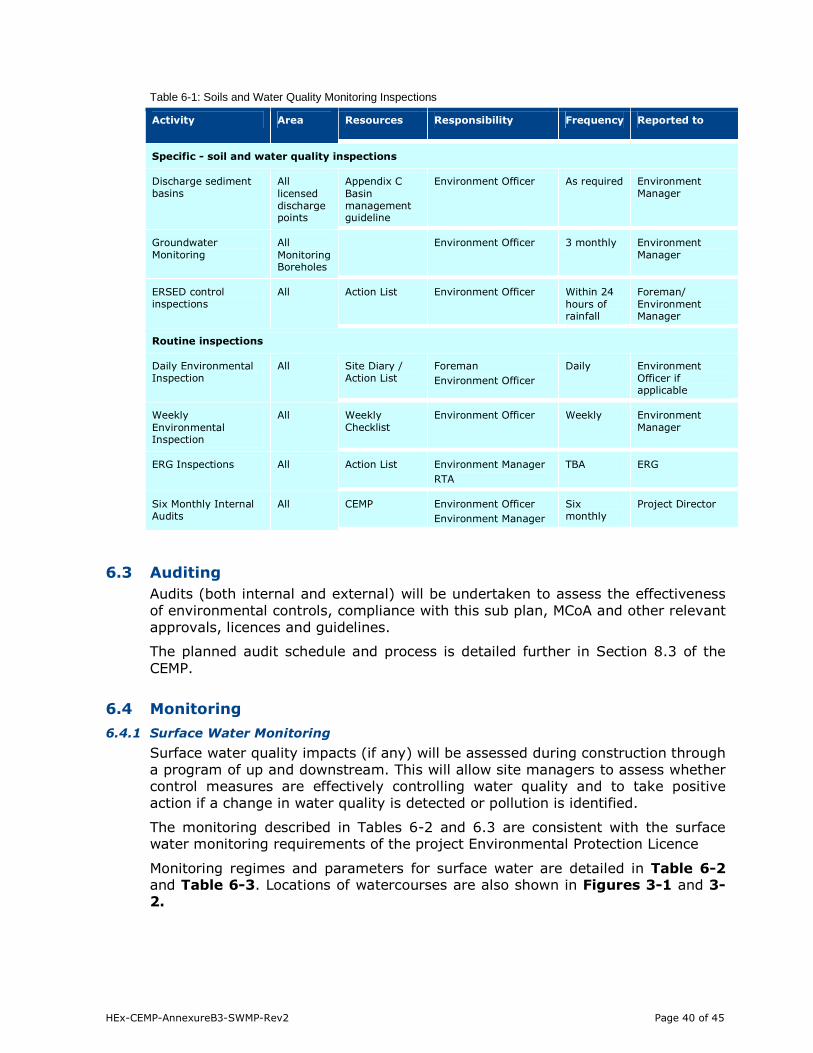
HEx-CEMP-AnnexureB3-SWMP-Rev2 Page 40 of 45
Table 6-1: Soils and Water Quality Monitoring Inspections
Activity Area Resources Responsibility Frequency Reported to
Specific - soil and water quality inspections
Discharge sediment basins
All
licensed discharge points
Appendix C
Basin management guideline
Environment Officer As required Environment Manager
Groundwater
Monitoring
All
Monitoring Boreholes
Environment Officer 3 monthly Environment
Manager
ERSED control inspections
All Action List Environment Officer Within 24
hours of rainfall
Foreman/
Environment Manager
Routine inspections
Daily Environmental Inspection
All Site Diary / Action List
Foreman
Environment Officer
Daily Environment
Officer if applicable
Weekly
Environmental Inspection
All Weekly
Checklist
Environment Officer Weekly Environment
Manager
ERG Inspections All Action List Environment Manager
RTA
TBA ERG
Six Monthly Internal Audits
All CEMP Environment Officer
Environment Manager
Six monthly
Project Director
6.3 Auditing
Audits (both internal and external) will be undertaken to assess the effectiveness
of environmental controls, compliance with this sub plan, MCoA and other relevant
approvals, licences and guidelines.
The planned audit schedule and process is detailed further in Section 8.3 of the
CEMP.
6.4 Monitoring
6.4.1 Surface Water Monitoring
Surface water quality impacts (if any) will be assessed during construction through
a program of up and downstream. This will allow site managers to assess whether control measures are effectively controlling water quality and to take positive
action if a change in water quality is detected or pollution is identified.
The monitoring described in Tables 6-2 and 6.3 are consistent with the surface water monitoring requirements of the project Environmental Protection Licence
Monitoring regimes and parameters for surface water are detailed in Table 6-2 and Table 6-3. Locations of watercourses are also shown in Figures 3-1 and 3-2.

HEx-CEMP-AnnexureB3-SWMP-Rev2 Page 41 of 45
Table 6-2: Surface Water Quality Monitoring Sites
Table 6-3: Surface Water Quality Monitoring
Stage of Works Frequency Description
Pre-Construction Monthly Monitoring will commence prior to construction to assess baseline quality and condition. Where possible monitoring shall occur no later than two months prior to construction activities commencing in that area. To gauge baseline/background conditions it will be preferable to conduct sampling for timeframes such as a year to assess seasonal fluctuations,
however this may not be practicable due to construction timeframes and project award.
Construction Monthly General monitoring will be undertaken monthly during the construction
period. Monitoring will target both dry weather periods and following rain events
Bridge Foundation Construction
Bi-Monthly Where permanent water is present, monitoring will also occur at the
smaller creeks/drainage channels (for culverts) during construction in those areas.
Monitoring equipment providing immediate results will be used where available such as handheld multi-probes (pH, EC/Salinity, Temperature, Turbidity). Further,
the monitoring will be conducted by using a calibrated instrument for the abovementioned parameters. Total suspended solids (TSS) will be measured using
turbidity a probe (measuring NTU) with a correlation developed between TSS and
NTU using local sediments in accordance with the project EPL. Additional confirmatory TSS samples may require laboratory analysis. Where laboratory
analysis of samples is required, the results will be requested as soon as possible and assessed by the Environmental Manager immediately upon receipt.
Monitoring Site ID Location
Description
Approx
Station
Water Quality Monitoring
Requirement
Site 1a (Upstream)
Site 1b (Downstream)
Swamp Creek 15900 pH, EC/Salinity, Temperature,
Turbidity, Oil and Grease
Site 2a (Upstream)
Site 2b (Downstream)
Black Waterholes 18320 pH, EC/Salinity, Temperature, Turbidity, Oil and Grease
Site 3a (Upstream)
Site 3b (Downstream)
Sawyers Gully Creek 22300 pH, EC/Salinity, Temperature, Turbidity, Oil and Grease
Site 4a (Upstream)
Site 4b (Downstream)
Bishops Creek 24450 pH, EC/Salinity, Temperature, Turbidity, Oil and Grease
Site 5a (Upstream)
Site 5b (Downstream)
Anvil Creek 28600 pH, EC/Salinity, Temperature, Turbidity, Oil and Grease
Site 6a (Upstream)
Site 6b (Downstream)
Sawyers Creek 32600 pH, EC/Salinity, Temperature, Turbidity, Oil and Grease
Site 7a (Upstream)
Site 7b (Downstream)
Anvil Creek 35950 pH, EC/Salinity, Temperature, Turbidity, Oil and Grease
Site 8a (Upstream)
Site 8b (Downstream)
Black Creek 38700 pH, EC/Salinity, Temperature, Turbidity, Oil and Grease

HEx-CEMP-AnnexureB3-SWMP-Rev2 Page 42 of 45
Monitoring at each site will be carried out only where there is water flow between
the upstream and downstream monitoring locations. Where no flow is observed,
this will be recorded as the monthly monitoring result for that location.
If monitoring results show a difference between upstream and downstream levels
of greater than a 10% increase in any pollutant measured, the Environmental
Officer shall undertake an investigation to determine if the project contributed to
the increase. Results of investigations, including any remedial action taken, will be included in monthly reports to DECCW.
Where concerns are identified, the results will be discussed with relevant staff and
a Soil Conservationist or specialist. Where the cause of the exceedence can be identified and it is related to an activity occurring on the project, action will be
taken to rectify the problem. This may involve:
• providing additional environmental controls;
• consulting a Soil Conservationist for advice;
• refining this SWMP;
• reviewing site management practices or work methods;
• referring to specialist advice regarding ASS assessment or remediation / treatment; and
• providing further training to personnel and sub-contractors.
6.4.2 Groundwater
Construction works may potentially impact groundwater either through interceptions in cut areas, direct extraction from groundwater aquifers or indirect
impact through aquifer compaction or contamination.
Groundwater has not yet been identified as a source of water for the project,
however investigations may be required if captured water, purchased irrigation water and treated water from STPs cannot meet project demand.
If groundwater is required for construction purposes, a hydrogeologist will be
engaged to assist with conducting investigations, obtaining appropriate licences and monitoring extraction rates and associated impacts.
In the event that groundwater is intercepted during cuttings, or boreholes are
required and show issues with recharge rates or drawdown capacities, the response processes detailed in Section 6.5.1 will be implemented.
A minimum of four groundwater monitoring boreholes will be established along the
alignment and groundwater level will be monitored every three months. Any
additional ground water monitoring requirements will be added to Table 6-1.
6.4.3 Sediment Basins
Water quality monitoring of sedimentation basins will be undertaken prior to
release of water into receiving environments in accordance with Managing Urban Stormwater: Soils and Construction, Landcom, (4th Edition) March 2004 (the
“Blue Book”) Volume 1 and Volume 2. This is further detailed in Appendix C.
6.5 Incident Planning and Response
The Soil and Water Management Sub-Plan provide details on emergency incident response procedures. Typical emergency situations that may impact on soil and
water management have been identified in the risk assessment.
HEx-CEMP-AnnexureB3-SWMP-Rev2 Page 43 of 45
Typical emergency response procedures as detailed in the CEMP and Hazard and
Risk Management Plan (HRMP) include:
• contain and control environmental emergency incidents where possible;
• safeguard people on-site and off-site;
• notify supervisor and follow the chain of command;
• Abigroup will advise the RTA and DECCW (as appropriate);
• protect watercourses, wetlands and adjacent vegetation;
• minimise damage to property and environment;
• remove and dispose of any contaminated soil and clean up materials;
• remediate the area where the incident occurred to the satisfaction of
authorities and Abigroup;
• complete an environmental incident report form; and
• investigate corrective actions and amendment to procedures where
applicable to prevent a recurrence.
Incidents specific to the management of groundwater and the appropriate
response processes are detailed below.
6.5.1 Groundwater Interception
In the event that groundwater is intercepted the following procedure is to be
adopted:
• site Geotechnical Representative and Environment Officer to be contacted;
• geotechnical inspection to be carried out;
• recommendation made of subsurface drainage measures (e.g. subsoil trench drain, drainage blanket, etc) appropriate to particular situation;
• Environment Officer to ensure groundwater interception location is included
on the groundwater licence for the project issued by NSW Office of Water;
• subsurface drainage system outlet location and treatment (e.g. scour
protection) to be approved by Environment Officer;
• measures to manage intercepted groundwater to be identified by the Environment Manager and Superintendent;
• RTA Senior Environmental Officer (SEO) to be notified if required; and
• NOW / DECCW to be notified if required on the advice of the RTA SEO.
Subsurface drainage filter material may consist of clean aggregate (crushed rock,
river gravel, or, in some instances, sand) meeting the requirements of RTA R32 or
R44 as appropriate, and will be wrapped in geofabric where there is potential for ingress of fines. Subsoil pipes may also be wrapped in geofabric filter sock to
further reduce potential for transport of fines to outlet.
Abigroup will aim to direct the water back to the natural environment where possible or beneficially reuse the water where this cannot be achieved during
construction.
6.5.2 Groundwater Over-extraction
If groundwater extraction is required, all licences will be obtained from NOW and extraction limits adhered to. In the unlikely event that water quality or
groundwater levels drop beyond those deemed to be sustainable by the project
hydrogeologist, management measures will be implemented that may include:
• reducing the discharge rate;
• increasing the rest time between pumping intervals;

HEx-CEMP-AnnexureB3-SWMP-Rev2 Page 44 of 45
• rotating the pumping bores;
• using alternative water supplies on a temporary basis; and/or
• drilling and installing alternative production bores.
If, however, the impacts have spread sufficiently far to impact on other users,
result in changes to the aquifer or cause environmental degradation, the
Environment Manager will contact the RTA SEO and upon advice from the SEO,
then contact NOW.
6.6 Reporting
Reporting will be undertaken by the Environment Manager as described in Section
9 of the CEMP. This will include as a minimum monthly reports and six monthly compliance reports to the RTA. Each report will detail relevant training,
inspections, monitoring and auditing undertaken for the reporting period relating
to soil and water management on the project.
In addition, a monthly report will be provided to DECCW, detailing the results of
all discharges from sediment basins where the licence conditions were exceeded
and the results of the rainfall measurements.

HEx-CEMP-AnnexureB3-SWMP-Rev2 Page 45 of 45
7.0 Review and Improvement of the SWMP
7.1 Continual Improvement
Continual improvement of this plan will be achieved by the continual evaluation of
environmental management performance against proposed control measures, environmental policies, objectives and targets for the purpose of identifying
opportunities for improvement. Evaluation against the above will be undertaken as described in Section 6.2 and 6.3 of this SWMP.
The continual improvement process will be designed to:
• identify areas of opportunity for improvement of environmental management which leads to improved environmental performance;
• determine the root cause or causes of non-conformances and deficiencies;
• develop and implement a plan of corrective and preventative action to
address non-conformances and deficiencies;
• verify the effectiveness of the corrective and preventative actions;
• document any changes in procedures resulting from process improvement;
and
• make comparisons with objectives and targets.
7.2 Plan Update
As described in Section 10 of the CEMP, between the scheduled audits and
reviews, a register of issues will be maintained to ensure that any issues are
recorded for future action.
Changes to this plan will be approved by the client, Environmental Management
Representative and stakeholders (if required) and documented in the document
control section for each revision.
The Environmental Management Representative will certify revisions of each plan and determine whether approval from the Department of Planning is required, as
detailed in section 1.7 of the CEMP.
A copy of the updated plan and changes will be distributed to all relevant stakeholders.

Appendix A
Scope of Works Technical
Criteria
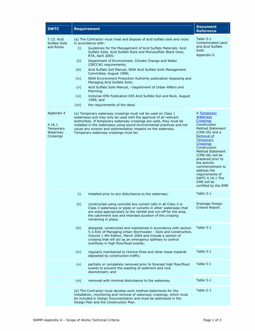
SWMP-Appendix A – Scope of Works Technical Criteria Page 1 of 3
SWTC Requirement Document Reference
7.13. Acid
Sulfate Soils and Rocks
(a) The Contractor must treat and dispose of acid sulfate soils and rocks
in accordance with:
(i) Guidelines for the Management of Acid Sulfate Materials: Acid Sulfate Soils, Acid Sulfate Rock and Monosulfidic Black Ooze, RTA, April 2005;
(ii) Department of Environment, Climate Change and Water (DECCW) requirements;
(iii) Acid Sulfate Soil Manual, NSW Acid Sulfate Soils Management Committee, August 1998;
(iv) NSW Environment Protection Authority publication Assessing and Managing Acid Sulfate Soils;
(v) Acid Sulfate Soils Manual, –Department of Urban Affairs and
Planning;
(vi) Victorian EPA Publication 655 Acid Sulfate Soil and Rock, August 1999; and
(vii) the requirements of the deed.
Table 5-1 Contaminated Land
and Acid Sulfate Soils
Appendix G
Appendix 4
4.16.1 Temporary Waterway Crossings
(a) Temporary waterway crossings must not be used on Class 1 waterways and may only be used with the approval of all relevant Authorities. If temporary waterway crossings are used, they must be installed in the waterways using sound environmental practices and not
cause any erosion and sedimentation impacts on the waterway. Temporary waterway crossings must be:
A Temporary
Waterway Crossings Construction Method Statement (CMS 05) and a Removal of
Temporary Crossings Construction Method Statement (CMS 06) will be prepared prior to the activity commencement to
address the requirements of SWTC 4.16.1 The CMS will be certified by the EMR
(i) installed prior to any disturbance to the waterway; Table 5-1
(ii) constructed using concrete box culvert cells in all Class 2 or Class 3 waterways or pipes or culverts in other waterways that are sized appropriately to the rainfall and run-off for the area, the catchment size and intended duration of the crossing remaining in place;
Drainage Design Criteria Report.
(iii) designed, constructed and maintained in accordance with section
5.3.4(b) of Managing Urban Stormwater - Soils and Construction, Volume 1 4th Edition, March 2004 and include a section of crossing that will act as an emergency spillway to control overflows in high flow/flood events;
Table 5-1
(iv) regularly maintained to remove fines and other loose material deposited by construction traffic;
Table 5-1
(v) partially or completely removed prior to forecast high flow/flood events to prevent the washing of sediment and rock downstream; and
Table 5-1
(vi) removed with minimal disturbance to the waterway. Table 5-1
(b) The Contractor must develop work method statements for the installation, monitoring and removal of waterway crossings, which must be included in Design Documentation and must be addressed in the Design Plan and the Construction Plan.
Table 5-1

SWMP-Appendix A – Scope of Works Technical Criteria Page 2 of 3
4.16.2 Waterway Working Platforms
(a) Working platforms must not be used in waterways unless approved by
all relevant Authorities. If waterway working platforms are used, they must be installed in the waterways using sound environmental practices and not cause any erosion and sedimentation impacts on the waterway. Waterway working platforms constructed from rock must:
(i) be constructed from rock materials which do not contain any fine materials;
(ii) be designed to prevent small rock or fine capping materials from
being washed out of the platform;
(iii) be designed to prevent overtopping of the platform below the 1 in 6 month average recurrence interval event and to prevent scour of the waterway during this event;
(iv) be wrapped in geotextile materials;
(v) remain in the waterway for the minimum time possible;
(vi) include large rock armouring on all the external faces;
(vii) be protected by anti-pollution booms; and
(viii) include appropriate water flow and/or fish passage treatments.
A Working in Watercourse Areas Construction Method Statement
(CMS 07) will be prepared prior to the activity commencement to address the requirements of SWTC 4.16.2. The
CMS will be certified by the EMR
Table 5-1
(b) The Contractor must develop work method statements for the installation, monitoring and removal of waterway working platforms, which must be included in Design Documentation and must be addressed in the Design Plan and the Construction Plan.
Table 5-1
Appendix 14
14.2.1 Construction Sediment Basins
(a) The Contractor must optimise the sediment control capability of construction sediment basins and minimise the periods required to restore the construction sediment basins to design capacity during performance
of the Contractor’s Work.
Table 5-1:
Sediment Basins and Captured Water Appendix B
Appendix C
(b) The design, construction and operation of construction sediment basins must comply with the requirements of Managing Urban Stormwater: Soils and Construction, Volume 1 4th Edition, March 2004, Managing urban stormwater: Soils and construction, Volume 2D Main Road Construction and RTA D&C G38 in Appendix 6.
Appendix B
Appendix C
Table 5-1: Sediment Basins and Captured Water
(c) The construction sediment basins and associated equipment must include:
(i) flow control baffles at the inlet of the construction sediment basin that form an inlet chamber and limit flows to a maximum velocity to 0.5m/s. The size and location of the inlet chamber must allow desilting by
conventional earthmoving equipment such as a backhoe;
(ii) internal baffles where the length-to-width ratio of the construction sediment basin is less than 3:1;
(iii) automatic basin flocculent dosing stations that comply with the requirements of E.4.2 of Managing Urban Stormwater: Soils and Construction Volume 1 4th Edition, March 2004 and use liquid flocculants that comply with the requirements of RTA D&C G38. For the avoidance of
any doubt, polyaluminium chloride is not permitted to be used as a flocculent; and
(iv) floating siphon devices that decant the construction sediment basin by siphoning water from the top of the water column.
Appendix C
Table 5-1: Sediment Basins and Captured Water
14.2.2 Operational Water Quality Control
The Contractor must design and construct an operational water quality
system that may include swales, bioretention base ponds and constructed wetlands to control the intensity of and remove pollutants from stormwater runoff (including from pavements and bridges) prior to discharge.
The Contractor must design and construct the Project Works to achieve the water quality criteria outlined in Table 2 during operation of the Works.
This is an operational issue and would be addressed in the
RTA’s existing environmental management Plans.
14.2.3 Spill Containment
(a) The Contractor must design and construct a spill containment system to capture accidental chemical and fuel spills during operation of the Works and minimise the impacts of accidental spills, including those on environmentally sensitive areas.
Table 5-1
Drainage Design Criteria Report.
(b) Spill containment system infrastructure that caters for a minimum
spill of 20,000 litres must be provided at each of the following locations:
Drainage Design Criteria Report.

SWMP-Appendix A – Scope of Works Technical Criteria Page 3 of 3
(i) Swamp Creek;
(ii) Black Creek;
(iii) Anvil Creek ;
(iv) Bishops Creek;
(v) Camp Road;
(vi) rest areas;
(vii) Kurri Kurri Interchange;
(viii) Loxford Interchange;
(ix) Allandale Road Interchange; and
(x) Branxton Interchange.

Appendix B
Sediment basin design and construction guideline

SWMP-Appendix B – Sediment basin design and construction guideline Page 1 of 3
Sediment Basin Design & Construction Guideline
Purpose
This guideline aims to provide the relevant information to all project personnel to appropriately
design and construct temporary sediment basins to capture and treat stormwater. The design and operation of the sediment basins should optimise their sediment control capability and minimise the
periods required to restore the them to design capacity.
Scope
The scope of this guideline is only the sizing, design and construction of sediment basins. This guideline is split into two sections:
1. Sediment Basin Sizing
2. Sediment Basin Design & Construction
The management of water captured in basins is detailed further in the Sediment Basin Management Guideline (Appendix C).
Step 1 - Sediment Basin Sizing
There are two basic calculations that need to be applied to determine the capacity of a sediment
basin. These allow you to determine the volume of sediment that you are going to capture in a certain period of time, as well as, the volume of water that will be captured by this basin in a certain
period of time.
Calculation 1: Revised Universal Soil Loss Equation (RUSLE)
This equation allows you to calculate the storage volume, that is, the volume of sediment that will be
captured over a period of time.
A = R x K x LS x P x C
Where:
A = Calculated Soil Loss (tonnes per hectare per year)
R = Rainfall erosivity factor (Appendix B, Blue Book)
K = Soil erodibility factor (Appendix C, Blue Book)
LS = A slope length/gradient factor (Page A-9, Blue Book. Note, the slope lengths should never
extend longer than 80m onsite, consider segmenting longer slopes with cut drains, berms etc.)
C = Ground cover and management factor (Table A-3, Blue Book), = 1.0 (default value).
P = Erosion control practice factor (Appendix A Section A5, Blue Book), 1.3 used as a default factor.
Multiply your answer by the size of your upstream catchment (in hectares). This will give you
tonnes/catchment size/year.
Divide by the soil density for m3/catchment size/year.
Adjust for the sediment yield duration. This is now your final storage volume for the sediment basin in m3.
Calculation 2: Settling Zone for Type D/F Basins The settling zone volume for Type F and Type D soils is calculated to provide capacity to contain all
runoff expected from up to the y-percentile rainfall event. The volume of the basin's settling zone
can be determined as a function of the basin's surface area and depth to allow for particles to settle and can be determined by the following equation:
Settling Zone = 10 x Cv x A x R(y%ile, 5 day)
Where:
Cv = Volumetric runoff coefficient (Appendix F, BlueBook)
A = Area of catchment (hectares)
R(y %ile, 5 day) = is the x-day total rainfall depth (mm) that is not exceeded in y percent of rainfall
events.

SWMP-Appendix B – Sediment basin design and construction guideline Page 2 of 3
Calculation 3: Final Basin Size
Storage Volume + Settling Volume = Final Basin Size (m3)
(from calculation 1) and (from calculation 2)
Step 2 - Sediment Basin Design & Construction
Basin Design
Basin design will be based on the required size from Step 1 and also as per Standard Drawing 6–4
attached for construction sediment basins and relevant sections of RTA Specification G 38 - Section 4
and Managing Urban Stormwater: Soils and Construction, Volume 1 4th Edition, March 2004,
Managing urban stormwater: Soils and construction, Volume 2D Main Road Construction and SWTC
requirements, including:
The construction sediment basins and associated equipment must include:
(i) flow control baffles at the inlet of the construction sediment basin that form an inlet chamber
and limit flows to a maximum velocity to 0.5m/s. The size and location of the inlet chamber must allow desilting by conventional earthmoving equipment such as a backhoe;
(ii) internal baffles where the length-to-width ratio of the construction sediment basin is less
than 3:1;
(iii) automatic basin flocculent dosing stations will be trialled in consultation with DECCW, RTA and the EMR, and if successful, utilised where feasible on site. The automatic dosing stations will
comply with the requirements of E.4.2 of Managing Urban Stormwater: Soils and Construction Volume 1 4th Edition, March 2004 and use liquid flocculants that comply with the requirements
of RTA D&C G38 (not polyaluminium chloride); and
(iv) floating siphon devices that decant the construction sediment basin by siphoning water from
the top of the water column.
Basin Construction
On site personnel will ensure basins are constructed as per basin design drawings and an Inspection and Test Plan (ITP) checklist is completed prior to commissioning.
Basin construction will also be conducted in accordance with Standard Drawing 6–4 below.

SWMP-Appendix B – Sediment basin design and construction guideline Page 3 of 3

Appendix C
Sediment basin management
guideline

SWMP-Appendix C – Sediment basin management guideline Page 1 of 4
Sediment Basin Management Guideline Purpose
This guideline outlines the steps to be followed so that sediment basin dewatering is effectively
managed to ensure that captured stormwater on site is sampled, treated and discharged to maintain compliance with the water quality criteria during construction.
General
Sediment Basins are to be managed to ensure water levels are returned to design capacity with 5
days of rainfall.
Where ever possible water is to be used for construction purposes (e.g. compaction, dust control)
rather than discharged to drains or water courses.
Water testing and treatment should commence approximately 2 to 4 days before dewatering
deadline to allow enough time for settlement of flocculants.
Testing Treatment and discharge should be undertaken as follows:
Scope
This document consists of three related guidelines to ensure effective basin management. These are:
1. Water Sampling
2. Water Treatment
3. Water Discharge
Procedure 1 – Water Sampling
When sediment basins or other water on the Project site is required to be discharged from the
Project site during construction, the safety aspects from the relevant SWMS shall be complied with
and the following steps shall be taken:
Step 1. Taking Samples
Quality Assurance
Always use clean sampling containers;
Always fill sample bottle to close to maximum – try not to leave an air space in sample bottle;
If immersing sample bottle into water try not to disturb bottom sediment and do not allow mud to
enter container;
Preferably take samples from just below the water surface.
Step 2. Field Monitoring and Analysis
Sampling methods
A grab sample is a discrete sample taken manually. Each sample is representative of water quality only at the time and place at which it is taken.
Lower the sample container into the sedimentation basin by hand or with a weighted rope, let the
container fill up through the top ¾ of the basin depth, then remove when full.
ph will be analysed by the use of a turbidity tube or probe in a grab sample as described.
Oil and grease will be assessed by visible and olfactory means e.g. sheen and/or reflection of colours
on the surface of the sediment basin water, smells of diesel, fuel, distinct chemical smell.
Step 3. Sediment Basin Treatment
1. If the sample parameters after field testing are compliant the requirements for discharge,
record the results and proceed to Step 4.
2. If the sample parameters are not compliant with the requirements for discharge, the basin will require treatment that may be conducted as described in Procedure 2.
Step 4. Sample handling and dispatch to the Laboratory (where required)
1. Ensure samples are correctly labelled - using a permanent marker, include dates, name of
sampler and sample / basins number or locations

SWMP-Appendix C – Sediment basin management guideline Page 2 of 4
2. The chain of custody (COC) form must be completed in full and copies kept.
3. Ensure at least 1 frozen ice pack is contained in the sample esky and that the esky is kept in a cool place prior to dispatch.
4. Ensure samples are delivered to the laboratory within 48 hours of the sample being taken.
5. Ensure sufficient sampling bottles, jars, ice packs, eskies, chain of custody (COC) sheets etc
are available on-site. Request additional sampling equipment from laboratory when dispatching any samples.
6. Once laboratory results have been received the results will be recorded and reported as necessary as part of the regular reporting process.
Procedure 2 - Basin Treatment with Gypsum
There are various ways that gypsum can be applied to basins including:
1. The first, and typically the least effective means of applying gypsum as a flocculating agent
is via hand broadcasting. The gypsum is applied at approximately 30-50Kg (gypsum):
100m³ (basin size) and spread evenly by hand across the surface of the basin.
2. The second method is a far more effective method of treating the basins and takes much
less time for the flocculation to occur. This method will require a reasonably large drum with holes punctured into it; some gypsum; a shovel and a flex-drive pump with a nozzle on the
outlet.
A suggested process is detailed below:
Step 1.
Place a well perforated steel drum into the basin, beside your quantity of gypsum, with the open end of the drum pointing up. Secure the drum if necessary.
Step 2.
Place the inlet/suction hose of the pump into the drum. Start the pump and have one worker spray
the jet of water evenly across the basin surface.
Step 3.
The other worker can now start to shovel gypsum into the drum / pump pick up until the required
amount of gypsum has been applied to the basin. Record quantity and time the basin was treated on
the Sediment Basin Checklist.
Step 4.
Allow 24 - 72 hours for the applied gypsum to work, sometimes it may work in less time and in other instances it may take longer. If further rain is received during this settling period then the process
may have to be re-done depending on the condition of the water. If re-treating, do not reapply the gypsum at such a high concentration/application as some of the active ingredients will remain in the
water from the previous application.
Step 5.
Once sufficient time has passed and the water appears noticeably clearer, the water should be tested as described previously. Note that it is imperative that a water sample be acquired from the basin
prior to discharge and to meet relevant criteria.
The pH of discharge waters must be between 6.5 and 8.5. For each pH unit it is below 6.5, add
approximately half a bucket of lime per 100m3 of basin capacity. Lime should be broadcast evenly by hand across the surface of the basin. The lime should be allowed at least 4 hours to balance the pH

SWMP-Appendix C – Sediment basin management guideline Page 3 of 4
and then the basin can be tested again. If the pH is still under the required discharge criteria, then
allow more time for the lime to take affect or broadcast a little more lime across the basin.
Step 6.
After the basin has been passed in regards to EC, pH, turbidity, approval must be given by the Environment Officer.
Step 7.
Once approval from the EO is given, Procedure 3 - Basin Discharge Procedure should be followed for
dewatering.
Procedure 3 - Basin Discharge
The suggested discharge process is detailed below:
Step 1. Read and sign SWMS and check basin id signs.
Check with the EO that the basin has been passed in regards to EC, pH, and turbidity and a sample
has been acquired to provide to the laboratory. Make sure you are discharging from the correct basin.
Step 2. Ensure the inlet to the discharge pipe / hose is floated so as to only discharge clean water from the top of the water column
The purpose of the float is to keep the inlet (the sucking end) off the silt at the bottom of the basin. As the basin empties and the float is no longer effective at keeping the inlet hose off the silt at the
bottom of basin, the discharge must be ceased immediately, even if some water is left in the bottom of the basin. It is normal for a basin to have a little bit of water in it most of the time.
Step 3. Make sure the inlet hose is floated and away from basin wall or floor.
Insert / install the inlet/suction hose into the basin so that it is away from basin wall or floor and unable to pick up any sediment. The float which has been attached should suspend it on top of the
water, if it doesn’t, attach another float or a bigger float that will keep the inlet hose at the surface.
Step 4. Discharge water onto stabilised surfaces.
Discharge onto rock or bidum.
Run the discharge pipe off-site remembering that if it is into a paddock we can only allow sheet flows
to exit the site so the discharge outlet and surrounding area should be protected by laying some bidum or rock down at the hose outlet, which shall allow the water to dissipate and exit as sheet
flow.
Step 5. Stop discharging before the bottom of the basin is reached.
Once the floated inlet hose is approaching the bottom of the basin as it empties (prior to it sucking sediment-laden water), the discharge must be stopped.
Step 7. Check the sediment depth marker.
Ensure that the sediment in the basin does not exceed the sediment storage capacity of the basin as
indicated on the marker. If the sediment has reached 60% of the sediment storage capacity as
shown on the marker, contact the EO who will arrange to have the sediment removed. Removed sediment will where possible be incorporated with fill material and reused on site. Where sediment
can not be reused on site it will be disposed of in accordance with the Waste and Reuse Management Plan.

SWMP-Appendix C – Sediment basin management guideline Page 4 of 4
Sediment Basin Checklist
Project: Date Inspected:
Basin No.: Location/Chainage:
Is inspection following a rainfall event? Yes No
If yes record rainfall for previous 24 hours: Rainfall mm
What is the approximate volume of water in the basin (as a % of the total capacity)?
# Control Measure Yes No Comments
1. Is maintenance to the basin required? (e.g. spillway, wall
etc.)
2. Does the basin need emptying?
(i.e. basin more than 30% full – refer to marker)
3. Does the basin need de-silting?
(i.e. >30% capacity reduced by silt – refer to marker)
4. Is oil and/or grease visible on the surface of the water? (If
visible, remove using a suitable absorbent material).
5. What is the turbidity tube reading of the basin? Flocculate
basin before discharge if it does not meet required turbidity
standards (<50mg/L).
6. How much flocculant was added? (guide: 32 kg/100 cubic
metres)
7. What was the reading of the basin after flocculating?
8. What was the reading at the discharge point after
flocculating?
NOTE: the reading at the basin and the discharge point
may be different – ensure that the water at BOTH
monitoring points complies with the DECCW criteria.
9. What is the pH of water in the basin? pH must be between
6.5 and 8.5. If pH is below 6.5, add lime.
10. Measure and record pH again before discharge.
11. How long was the basin left to flocculate before being
discharged?
Hours
12. Has there been intercepted groundwater captured in the
sediment basin?
13. If groundwater has been captured are the salinity levels
high? (measure background and compare)
14. Date and time of discharge. Date: Time:
15. Duration and volume of discharge. Duration: Volume:
ALL PARTS OF THE CHECKLIST MUST BE COMPLETED
Additional comments:
Approved by: Discharged by:

Appendix D
Dewatering guideline (non-sediment basins)

SWMP-Appendix D – Dewatering Guidelines (Non Sediment Basins) Page 1 of 1
Dewatering Flowchart

Appendix E
Concept Erosion Sediment Control Plan (ESCP)

HUNTER EXPRESSWAY
KURRI KURRI TO BRANXTON SECTION
DESIGN AND CONSTRUCTION
PRIMARY / GENERIC EROSION AND SEDIMENT
CONTROL PLAN / STRATEGY
November 2010
Prepared by T.R.E.E.S. P/L for: Abigroup Contractors Pty Ltd
94 Toepfers Road WYEE NSW 2259 Phone: (02) 4357 1112 Fax: (02) 4357 1095
Hunter Expressway – Kurri Kurri to Branxton
T.R.E.E.S. P/L 1
TABLE OF CONTENTS 1.0 INTRODUCTION.......................................................................................................... 2 2.0 PROJECT DESCRIPTION ............................................................................................ 2 3.0 SCOPE OF THIS PLAN ................................................................................................ 3 4.0 EXISTING ENVIRONMENT ....................................................................................... 4 4.1 Topography............................................................................................................ 4 4.2 Soil Types.............................................................................................................. 4 4.3 Rainfall .................................................................................................................. 4 4.4 Sensitive Areas...................................................................................................... 4 4.5 Erosion & Sedimentation Hazard.......................................................................... 5 5.0 SUPPORTING DOCUMENTATION ........................................................................... 5 6.0 KEY MANAGEMENT STRATEGIES.........................................................................5 6.1 Professional Expertise ........................................................................................... 5 6.2 Detailed Design ..................................................................................................... 5 6.3 Training ................................................................................................................. 6 6.4 Minimising Extent and Duration of Disturbance .................................................. 6 6.5 Control of Stormwater Flows onto, through and from the Site............................. 6 6.6 Erosion Control Measures to Prevent On-Site Damage........................................ 7 6.7 Sediment Control Measures to Prevent Off-Site Damage..................................... 7 6.8 Stabilisation and Revegetation .............................................................................. 7 6.9 Inspection and Maintentance................................................................................. 7 6.10 Documentation and Recording.............................................................................. 8 6.11 General .................................................................................................................. 8 7.0 CONCLUSION .............................................................................................................. 8 8.0 ACKNOWLEDGEMENTS ........................................................................................... 8 9.0 ATTACHMENTS .......................................................................................................... 9
1 Register of Progressive Erosion and Sediment Control Plans 2 Sample Progessive Erosion and Sediment Control Plans 3 Curricula Vitae for Project Soil Conservationists - B J Wright & A Littlewood 4 Awareness Training Program

Hunter Expressway – Kurri Kurri to Branxton
T.R.E.E.S. P/L 2
1.0 INTRODUCTION The construction activities to be undertaken on this project have the potential to impact on soil and water resources. Land to be disturbed or cleared of vegetation is potentially subject to erosion by stormwater or wind action. Generally, soil particles eroded by stormwater runoff are transported downslope, usually settling in rivers, watercourses and wetlands etc (i.e. sedimentation). This may result in many adverse environmental impacts including: • Reduction in water quality, increased turbidity and nutrient enrichment of water bodies. • Damage to vegetation communities. • Disturbance to aquatic flora and fauna. • Increased potential for flooding. • Reduction in recreational values. • Reduction in aesthetic values. • Increased maintenance costs. • Promotion of weed growth. Additionally, erosion may be caused by wind moving unprotected soil particles. This action may result in adverse impacts including: • Loss of valuable soil. • Safety on and off site (e.g. traffic hazards). • Inundation of urban/industrial areas with severe nuisance value. This plan will form the initial “part of the chain” to minimise on-site erosion and off-site sedimentation and therefore reduce adverse environmental impact. 2.0 PROJECT DESCRIPTION The project consists of 26.5km of two lane dual carriageway construction between the Alliance project at Kurri Kurri and the tie-in to the existing New England Highway at Branxton. This includes the construction of interchanges at Cessnock Road, Hart Road, Lovedale Road and Branxton. Twenty-three (23) bridges will be constructed across the project including crossings of the Main Northern Railway at Branxton. The project will be constructed over old mine workings at Kurri Kurri and Greta. The project is due for completion in mid 2013.

Hunter Expressway – Kurri Kurri to Branxton
T.R.E.E.S. P/L 3
3.0 SCOPE OF THIS PLAN The Primary/Generic Erosion and Sediment Control Plan (ESCP) is a document which describes intentions and fundamental principles for the duration of the entire project. It is a Plan to be complimented by the preparation of more detailed Progressive (Site Specific) Plans prepared for: • The different stages of construction (e.g. Clearing, Grubbing, Stripping and Stockpiling
of Topsoil and Early Earthworks; Bulk Earthworks; Drainage; Paving). • Various work areas (e.g. bridges, culverts, offices and compounds, concrete batch plant
etc). The Progressive ESCPs will be prepared just prior to construction activity and generally on copies of A3 drainage drawings and indicate (were relevant): • Catchment areas (i.e. within and outside the road reserve). • Construction boundaries. • Access points and tracks (e.g. haulage). • Compounds and storage areas. • Stockpile sites. • Temporary work areas. • Borrow pits. • Material processing areas. • Concrete washout pit sites. • Permanent and temporary controls. Additionally, the Plans will provide design criteria for erosion and sediment controls from the Blue Book where relevant (e.g. sediment basins, diversion channels). In some instances, more than one (1) Progressive Plan may be required for an activity (e.g. drainage construction) due to: • Staging rendering the process complicated. • Change in the construction process, scope of work or work method. • Controls are found to be ineffective following rainfall. Progressive Plans will be prepared by both the Project Soil Conservationists and the Contractor’s environmental and field personnel in consultation with the Soil Conservationist to formulate practical documents for field reference. Additionally, Plans will be developed in consideration of other environmental aspects (e.g. vegetation). Sometimes these Plans will be developed jointly with Construction Work Method Statements (e.g. major drainage structures, bridges etc). The Plans will be entered onto a register (refer to Attachment 1) and placed behind to create a ‘living’ record of erosion and sediment control (refer to Attachment 2 for Sample Plans). The Progressive ESCPs are to be generally prepared according to R.T.A. Specification G38 (clause 3.1) and are to be read in conjunction with the Primary Plan.

Hunter Expressway – Kurri Kurri to Branxton
T.R.E.E.S. P/L 4
4.0 EXISTING ENVIRONMENT 4.1 Topography The topography generally consists of low, rolling hills and undulating rises intersected by creek flats and some lowland swamps. Most of the creeks and drainage areas are broad. Slopes are generally less than 5% but do range up to 20%. 4.2 Soil Types Soil Landscape groups identified across the project from the NSW Department of Land and Water Conservation Soil Landscape Sheets for Newcastle and Singleton are: • Bolwarra Heights. • Neath. • Branxton. All these groups have a high erosion potential especially under conditions of concentrated flow. Additionally, soil dispersibility may be a problem in some areas. 4.3 Rainfall The average annual rainfall for Cessnock which is just south of the project is approximately 750 mm with summer/autumn being the dominant period. Summer thunderstorms have an important bearing on rainfall intensity and potential erosion. The winter/spring period produces less reliable rainfall. 4.4 Sensitive Areas The numerous watercourses and drainage areas transversing the project should be regarded as sensitive with the main creeks being: • Swamp Creek. • Black Waterholes Creek. • Bishops Creek. • Anvil Creek. • Sawyers Creek. • Black Creek. Other sensitive areas may include: • Threatened flora species. • Threatened fauna species. • Aboriginal heritage sites. These areas could easily be impacted on by high sediment loads generated from erosion incidents.

Hunter Expressway – Kurri Kurri to Branxton
T.R.E.E.S. P/L 5
4.5 Erosion and Sedimentation Hazard It is expected a generally high erosion and sedimentation hazard will be created during the construction of this project due to a combination of factors including: • Large scale disturbance. • Soil type as summarised in Section 4.2. • Rainfall patterns with sometimes summer thunderstorms with high rainfall intensities
as described in Section 4.3. • Proximity to numerous creeks and watercourses as listed in Section 4.4. 5.0 SUPPORTING DOCUMENTATION This Erosion and Sedimentation Control Plan is based on the requirements and guidelines contained in the following manuals/documents: • Department of Housing (1998), Managing Urban Stormwater: Soils and Construction,
Vol 1, 4th Edition (i.e. Blue Book). • Department of Environment and Climate Change (2008), Managing Urban Stormwater:
Soils and Construction, Vol 2D, Main Road Construction. • Department of Conservation and Land Management (Revised Edition 1992). Urban
Erosion and Sediment Control. Hunt, J.S. (ed). The strategies and techniques detailed in the above documents are appropriate for the protection of the adjacent environment of this project. 6.0 KEY MANAGEMENT STRATEGIES The following list outlines principles and control measures that will be implemented on this project for minimising erosion and sedimentation. They have been identified as key issues and techniques to control erosion and sedimentation on many road construction projects over the last 30 years. These points collectively fulfil the principles of sound soil conservation practice as detailed in the previously mentioned manuals. This will ensure a ‘preventative’ rather than a ‘cosmetic or remedial’ approach to erosion and sediment control. Major emphasis will be placed on: 6.1 Professional Expertise • The engagement of professional Soil Conservationists from T.R.E.E.S. P/L with
extensive experience in road construction, who will co-ordinate and oversee all erosion and sediment control aspects during construction. Refer to Attachment 3 for CV’s for B J Wright and Andrew Littlewood.
6.2 Detailed Design • Specialist Soil Conservationist input including:
- Design and location of sediment basins; - Siting sediment basins to maximise capture of runoff from construction areas;

Hunter Expressway – Kurri Kurri to Branxton
T.R.E.E.S. P/L 6
- Siting sediment basins to also contain road spillages during operation; - Location and stabilisation of open drains (e.g. catch and berm drains); - Batter treatments; - Culvert design with consideration for a stable ‘clean’ water flow path during
construction; - Bridge design in sympathy with maintaining the integrity of drainage lines (e.g.
pier locations); - Dissipation of high-velocity flows.
6.3 Training • Highlighting the importance of soil conservation issues during site inductions. • Scheduling half-day awareness seminars early in the project for all personnel involved
in construction. The program will cover: - Environmental impacts; - Relevant legislation; - Principles of erosion and sediment control; - Techniques of erosion and sediment control. More details on the program appear in Attachment 4.
• Conducting advanced soil conservation seminars for personnel with special responsibilities. This may include training in flocculation and water-quality management of sediment basins for the specialist labour team or preparation of Progressive ESCPs.
• Continually addressing relevant matters at regular ‘toolbox’ meetings during the course of the project (e.g. maintenance of temporary controls).
6.4 Minimising Extent and Duration of Disturbance • Initially clearing and grubbing to leave the soil surface in a reasonably rough condition
with some surface vegetative cover. • Minimising disturbance of vegetation along the road corridor with special emphasis on
management of construction activities adjacent to watercourses. • Leaving watercourses undisturbed until culvert/bridge construction has commenced
and using the cut-stump method where possible instead of stump removal to further maintain stream bank stability.
6.5 Control of Stormwater Flows onto, through and from the Site • Separating ‘clean’ run-on water from ‘dirty’ (e.g. turbid) construction area run-off. • Constructing permanent drainage structures early in the project including:
- Sediment basins and traps; - Catch drains; - Culverts and associated inlet and outlet protection (e.g. dissipators).
• Maximising the diversion of turbid construction runoff into sediment basins. • Controlling run-off during the construction of embankments (e.g. fill shaping and the
construction of temporary dykes and batter drains). • Diverting formation run-off into pits and the stormwater drainage system as soon as
practical to reduce surface flow lengths.

Hunter Expressway – Kurri Kurri to Branxton
T.R.E.E.S. P/L 7
6.6 Erosion Control Measures to Prevent On-Site Damage • Siting stockpiles of soil material in low-hazard areas clear of watercourses. Additional
protection to be afforded with temporary vegetation, diversion banks and sediment control measures, if required.
• Constructing a range of erosion controls within the various road sub-catchments to compliment and increase the effectiveness and efficiency of sediment controls in the lower areas.
• Using geotextile linings to provide temporary surface protection in areas of concentrated flows (e.g. batter drains, culvert construction).
6.7 Sediment Control Measures to Prevent Off-Site Damage • Constructing control measures as close to the potential source of sediment as possible. • Ensuring sediment basin management of turbid water immediately after rain as
required with one or a combination of: - Flocculation with gypsum (or approved alternative flocculant); - Pump-out for construction purposes or dust control.
• Water not to be released from sediment basins prior to achieving acceptable water quality standards. Attachment 5 contains a procedure for water quality management in sediment basins.
• Managing water quality during de-watering activities (e.g. filtering techniques and flocculation with gypsum).
• Controlling the deposition of mud and soil material onto local roads. • Initiating a water quality monitoring program in the adjacent watercourses with results
analysed to determine the efficiency and effectiveness of implemented controls. 6.8 Stabilisation and Revegetation • Ensuring the success of the later revegetation program by utilising a good topsoil
management program. • Progressively revegetating disturbed areas utilising appropriate species. • Controlling dust through progressive revegetation techniques and water tankers etc. 6.9 Inspection and Maintenance • Ensuring the progressive and continual implementation and maintenance of temporary
erosion and sediment controls (e.g. sediment fences, diversion banks, diversion drains, sediment traps).
• Initiating a program to ensure regular maintenance of all erosion and sediment control measures. Sediment cleaned from structures, including sediment basins, to be deposited in a secure location where further pollution will not occur.
• Arranging regular inspections by the project soil conservationist or other key personnel to review and update control measures. Additional inspections will be conducted during and/or immediately following significant rainfall events to monitor the functioning of controls.

Hunter Expressway – Kurri Kurri to Branxton
T.R.E.E.S. P/L 8
6.10 Documentation and Recording • Developing relevant documentation and systems for recording erosion and sediment
control activities via: - Progressive ESCPs as detailed in Section 3.0; - Inspection reports completed by the project soil conservationist. A copy of the
format for this report appears in Attachment 6 and includes sections for location, control, recommendations/comment, action and ‘close-out’.
• ESCP maintenance checklists completed by nominated construction personnel. • Site notes distributed internally between environmental and construction personnel. • Meeting minutes. • Formal correspondence (e.g. RTA, Council, DECCW, Department of Primary
Industries). • Water quality monitoring results (e.g. sediment basins, upstream and downstream). 6.11 General • Forming a specialist labour team to construct temporary controls, including sediment
fences, batter drains on fill batters and flocculate sediment basins etc. • Ensuring erosion and sediment controls are installed at all sites associated with
construction activities including: - Access roads and tracks; - Office and compound sites; - Workshop areas; - Concrete batching plants; - Crushing and screening plants; - Extraction sties.
• Liaising with the relevant government authorities in relation to control measures in watercourses and creeks (e.g. Department of Water and Energy, Department of Primary Industries).
• Leaving temporary erosion and sediment controls in place until the disturbed catchments have over 70% vegetation cover.
7.0 CONCLUSION The strategies presented in this Plan are considered to appropriately address all issues relevant to erosion and sediment control and to minimise potential impact. Forward planning, adherence to a system of documentation and training will be key elements to ensure sound performance in the field. 8.0 ACKNOWLEDGEMENTS
• RTA, Hunter Expressway, Concept Erosion and Sedimentation Management Report, Murphy M & Ledlin D.

Hunter Expressway – Kurri Kurri to Branxton
T.R.E.E.S. P/L 9
• Department of Environment and Climate Change (2008), Managing Urban Stormwater: Soils and Construction, Vol 2D, Main Road Construction.
9.0 ATTACHMENTS
1 Register of Progressive Erosion and Sediment Control Plans 2 Sample Progessive Erosion and Sediment Control Plans 3 Curricula Vitae for Project Soil Conservationists - B J Wright & A Littlewood 4 Awareness Training Program

T.R.E.E.S. P/L
ATTACHMENT 1

T.R.E.E.S. P/L
PROJECT: HUNTER EXPRESSWAY – KURRI KURRI TO BRANXTON SECTION REGISTER – PROGRESSIVE EROSION AND SEDIMENT CONTROL PLANS
PLAN NO CHAINAGE / DESCRIPTION PERSONNEL INVOLVED IN
PREPARATION
DATE OF PREPARATION
SOIL CONSERVATIONIST
INITIALS & DATE
ENVIRONMENTAL MANAGER INITIALS
& DATE
SUPERCEDED BY PLAN NO /
COMMENT

T.R.E.E.S. P/L
ATTACHMENT 2

T.R.E.E.S. P/L

T.R.E.E.S. P/L

T.R.E.E.S. P/L
ATTACHMENT 3

T.R.E.E.S. P/L
Insert CV’s in here

T.R.E.E.S. P/L
ATTACHMENT 4

T.R.E.E.S. P/L
PROGRAM
EROSION AND SEDIMENT CONTROL
AWARENESS SEMINAR – HALF DAY
1 Introduction 2 Environmental Impacts – This session focuses upon the on-site and off-site
environmental impacts of erosion and sedimentation (e.g. water quality, fauna, flora etc). It concludes with an exercise listing all impacts.
3 Environmental Legislation – This session examines:
Relevant legislation (P.O.E.O. Act). Practical application in the field.
4 Principles of Erosion and Sediment Control – This session covers nine (9)
principles which include: Investigation of site features Planning Minimum disturbance Topsoil Control of run-off Minimisation of erosion Trapping sediment Progressive rehabilitation Maintenance
5 Techniques of Erosion and Sediment Control – This session includes the most
common techniques. Aspects covered include: Clearing Topsoil management Drainage and installation of permanent structures (e.g. culverts, catch drains
etc) Diversions banks Drains and channels Batter protection Revegetation Sediment basins and management Sediment traps Sand bags and their application Maintenance Miscellaneous matters (e.g. mud on local roads, dewatering, dust etc).
6 Field Inspection – This session examines techniques constructed in the field
together with associated discussions on Impacts, Legislation and Principles.

Appendix F
Acid Sulfate Soil Strategy

Hunter Expressway
Kurri Kurri to Branxton
Acid Sulfate Soils Strategy
� Rev1
� November 2010

Contents
1. Introduction 1
1.1. Introduction 1 1.2. Objectives 1 1.3. Background 1 1.4. Occurrence of PASS and AASS 3
2. Cause and Effect 4
2.1. Causes 4 2.2. Effects 4
3. Identification of ASS 5
3.1. Roles 6 3.2. Process 6 3.3. On Site Identification of Acid Sulfate Soils 6
4. Monitoring 7
5. Acid Sulfate Rock 8
Appendix A Acid Sulfate Soils Identification Protocol
Appendix B Sample Collection
Appendix C Treatment Pad Construction
Appendix D ASS Management and Treatment
Appendix E Contingency Options
Appendix F Disposal

SWMP-Appendix F-ASS Strategy-Rev1 PAGE 1 of 8
1. Introduction
1.1. Introduction
This management strategy has been prepared to reduce the potential for risk of
environmental damage caused by acidic leachate from acid sulfate soil (ASS)
and acid sulfate rock (ASR) disturbance, if encountered.
During EIS development, testing was undertaken which identified that ASS is
unlikely to be encountered in any of the cuttings along the alignment and that,
although it may exist in low lying areas below the water table, they would be
unlikely to be disturbed during construction.
The management strategy applies to subsurface construction activities and has
been prepared in general accordance with the RTA Guidelines for the
Management of Acid Sulfate Materials, April 2005. The management strategy
also addresses the requirements of DECCW requirements and the ASSMAC
Manual 1998.
1.2. Objectives
A key objective of this Plan is, to provide a framework outlining appropriate
environmental controls and procedures to be implemented during construction
activities to avoid or reduce potential adverse environmental impacts associated
with ASS and ASR disturbance, handling, treatment or disposal.
To achieve this objective, Abigroup will be required to conduct construction
activities in accordance with applicable legislation, standards and guidelines, of
which the relevant requirements are detailed in this strategy.
1.3. Background
There are two main types of Acid Sulfate Soils:
Potential Acid Sulfate Soils (PASS)
The iron sulfides are generally located beneath the water table in a layer of
waterlogged soil. This layer can be clay, loam or sand, and is often dark grey
and soft (buttery and gel like to touch). These soils are located in an oxygen
deficient environment (water prevents oxygen in the air reacting with the iron
sulfides when located below the water table). The sulfides in the PASS oxidise
once exposed to air with the potential to generate sulfuric acid on contact with
water. Oxygenated water can also cause oxidation reactions where water is
pumped into a shallow, oxygen deficient aquifer.

SWMP-Appendix F-ASS Strategy-Rev1 PAGE 2 of 8
Actual Acid Sulfate Soils (AASS)
When the iron sulfides are exposed to air and have oxidised, they are known as
actual acid sulfate soils. While some compounds in the soil (e.g. calcium
carbonate) can provide buffering to help neutralise acidic conditions, the
remaining acid moves through the soil on contact with water and can impact on
the surrounding soil, and the underlying groundwater. Where AASS is stockpiled
there is potential that rain events could result in impact to surface waters if
runoff is not managed. AASS may also have some potential acidity remaining
within the soils especially if they are of a fine grain (i.e. clays). AASS typically
has a low pH value (<4.0) and may contain mobile dissolved metals such as
aluminium which can be toxic to aquatic animals and plants.
A typical soil profile for ASS materials is provided below.
Figure 1. Typical Soil Profile for ASS (SMEC, 2009)

SWMP-Appendix F-ASS Strategy-Rev1 PAGE 3 of 8
1.4. Occurrence of PASS and AASS
Drainage of groundwater and excavation can expose PASS (where present) to
the air, causing oxidation and acid generation. Therefore, early identification and
control of PASS and / or AASS can result in a reduction of adverse
environmental damage/risk.
ASS occurs predominantly on coastal lowlands, with elevations generally below
5m Australian Height Datum (AHD). The NSW Acid Sulfate Soils Manual
(ASSMAC, 1998) notes that ASS are generally associated with the Holocene age
(last 10,000 years) sediments.
These sediments were deposited in specific conditions such as within mangrove
areas, saltmarsh, floodplain backswamps, coastal flats, seasonal or permanent
freshwater swamps that were once saline or brackish and open tidal waters such
as the beds of coastal rivers or lakes existed.
The EIS identified that ASS are unlikely to be encountered in any of the cuttings
along the alignment and that, although they may exist in low lying areas below
the water table, they would be unlikely to be disturbed during construction.
While the above conclusion from the EIS is generally true, Abigroup will be
undertaking further geotechnical investigations as part of early works to
determine the extents and depths of ASS in areas of piling and lowland
excavations.

SWMP-Appendix F-ASS Strategy-Rev1 PAGE 4 of 8
2. Cause and Effect
2.1. Causes
Construction activities can cause the oxidation of PASS material which in turn
can result in environmental impacts. Some of the causes are:
1) Excavation and exposure of PASS material.
2) Exposure of subsurface PASS material due to dewatering activities.
3) Settlement - Discharge of sub-surface water as a result of settlement
and reduction in available pore space (during settlement water is
‘squeezed’ out of the soil material), producing acidic leachate where it
flows through oxidised AASS.
4) Embankment settlement can depress the underlying material with
respect to the water table. In some circumstances heave at the toe of
the embankment by displacement may raise PASS material above the
water table.
5) Oxidation of pyrite in imported fill material.
2.2. Effects
Should any of the above causes eventuate, the following impacts may result:
� Release of aluminium, nutrients and heavy metals (particularly arsenic)
stored within the soil matrix;
Death or stunted growth of aquatic flora and fauna;
� Deoxygenation of waterways leading to suffocation of fish and other aquatic
animals;
� Mass mortalities of microscopic organisms;
� Increased light penetration due to water clarity;
� Loss of habitat;
� Persistent iron coatings; and
� Damage to infrastructure e.g. Corrosion of concrete, limestone.

SWMP-Appendix F-ASS Strategy-Rev1 PAGE 5 of 8
3. Identification of ASS
The following field procedures have been developed to determine whether the
soils may contain acid generating potential to levels requiring treatment. It has
been developed based on information provided in the NSW ASSMAC guidelines
(1998).
The following flow chart should be used to assist in the identification process.
ASS identification protocol and collection methodologies can be found in
Appendix A and Appendix B respectively.
Figure 2. ASS Identification Process
Identification of PASS or AASS
• Refer to acid sulfate soil risk maps
• Has groundwater been impacted during works
• Conduct visual assessment of excavations and excavated soils
• Note the colour and any odour of the soil which may indicate the
presence of ASS
pH Field Test
Use pH field kit
pH > 5.5
No Actual Acid Sulfate Soil (AASS).
Could still contain PASS
pH < 5.5
May be Acid Sulfate Soil. Place half the sample in
a freezer bag and place in freezer. Conduct an
Indicator test on the other half of the sample.
Conduct Indicator Test
Trained environmental staff to undertake indicator test to
confirm presence of PASS or AASS
No response to indicator test
No further action required
Reaction to indicator test
(Appendix A)
Send frozen sample to lab for verification of ASS

SWMP-Appendix F-ASS Strategy-Rev1 PAGE 6 of 8
3.1. Roles
The identification and assessment of potential impacts relating to acid sulfate
soils is the responsibility of the Environmental Manager, Environmental
Coordinators, Site Foreman and Project Engineers.
3.2. Process
Areas of increased risk, such as creek crossings, should be sampled and tested a
minimum of 5 days prior to work commencing in the area. Any areas identified
as containing PASS will be demarcated and soils in these areas will be managed
in accordance with this Plan.
ASS will be treated on a treatment pad as specified in Appendix C and
managed and treated in accordance with the strategy outlined in Appendix D.
Appendix E outlines a contingency strategy where ASS is identified
unexpectedly during construction activities.
Options for the off site disposal of ASS material are presented in Appendix F.
3.3. On Site Identification of Acid Sulfate Soils
Refer to Appendix A: Acid Sulfate Soils identification protocol

SWMP-Appendix F-ASS Strategy-Rev1 PAGE 7 of 8
4. Monitoring
With regard to potential ASS impacts, a programme of regular water quality
monitoring will be established involving monitoring of the water within creeks
and rivers adjacent to construction in areas where risk of ASS is identified.
Random checking of the pH of excavated materials will be carried out on site.
Additional testing will be arranged if pH levels are less than background values.
Where surface water and/or leachate collects within bunded treatment areas, the
water shall be tested for pH, turbidity and salinity (TSS) prior to discharge or
pumped directly to a sedimentation basin. Should pH results be lower than 5,
further treatment may be required. Any runoff or fines collected in the
settlement pond/sump will require assessment prior to decommissioning of the
stockpile area. Regular visual monitoring of PASS/AASS areas and surrounds
shall be undertaken to identify signs of ASS oxidation. This monitoring should
include detecting:
� Unexplained scalding, degradation or death of surrounding vegetation.
� Unexplained death or disease in aquatic organisms.
� Formation of the mineral jarosite and other acidic salts in exposed or
excavated soils.
� Areas of green-blue water or extremely clear water indicating high
concentrations of aluminium.
� Rust coloured deposits on plants and on the banks of drains, water bodies
and watercourses indicating iron precipitates.
� Black to very dark coloured waters indicating de-oxygenation.
� Area of black ooze (potentially indicating monosulfidic black oozes) typically
in drains and low lying areas.
Final validation sampling of treated soils will be conducted at the completion of
treatment to determine if the neutralisation process has been successful.
Validation sampling will be conducted in accordance with the Acid Sulfate Soil
Manual (ASSMAC, 1998).

SWMP-Appendix F-ASS Strategy-Rev1 PAGE 8 of 8
5. Acid Sulfate Rock
The following information relating to acid sulfate rock (ASR) is provided in
Section 6.8 of the Geotechnical Design, Hunter Expressway - Kurri Kurri to
Branxton, Volume IIIa: Technical Details (29 March 2010).
As part of geotechnical investigations, the RTA carried out exposure tests on
selected cores from several of the major cuts. Photographs of the cores taken
before and after a 3 month exposure period indicate that a significant proportion
of the apparently sound rock (sometimes logged as medium to high strength)
completely deteriorated to a fine slightly sandy silt. The causes of the rock
breakdown could include:
� Acid sulfate rock chemical reactions;
� Expansive clay minerals within the rocks; and
� Other chemical reactions affecting the rock matrix.
There are indications from visual inspection of the cores that some of the rocks
in the cuttings may be potential acid sulfate rocks. Chemical testing results also
indicated that out of the 157 test samples, 51% fall under the category of non
acid forming (NAF) rock, 24% under the low capacity potential acid forming
(PAF-LC) rock category and 25% under the moderate potential acid forming
(PAF) rock category.
Among all the tests, 65 samples are above the cut floors and only 10 (15%)
samples show PAF. Currently there is also not a clear correlation between the
type of rocks and the PAF rocks. It appears that the PAF rocks are randomly
distributed along the length of the project without any specific patterns and are
present in isolated pockets, based on limited and incomplete testing regimes.
Based on the above, a strategy has been developed as follows:
� Undertake further peroxide and chemical tests on materials derived from
cuttings (as per Appendix A and Appendix B).
� Develop a correlation between the peroxide and chemical test results.
� Use largely the peroxide tests during excavation to gain an understanding of
the distribution PAF rocks for each of the cuts.
� Should PAF rocks be found in the cuttings in significant concentrations or
quantities, the treatments will be considered in consultation between the
earthworks and geotechnical teams and could include mixing the PAF rocks
with NAF rocks for use in fills or encapsulating the PAF rocks within the core
of an embankment.
� When there is seepage from PAF rocks in a cut, the water will be collected in
a sedimentation pond and treated with lime dosing prior to the release of the
water.

ASS Strategy - Appendix A – ASS Identification Protocol
Appendix A – Acid Sulfate Soils & Rock Identification
Protocol
A.1 Step One: Visual Assessment
If working in an area of ASS and PASS, it is important to be able to recognise
indicators of actual acid sulfate soils to prevent further acidification of land and
waterways. These indicators include:
� cloudy green-blue water
� excessively clear water
� iron stains
� poor pasture
� scalded soil
� yellow jarosite
� ‘rotten egg’ smell
� waterlogged soil
� corrosion of concrete and/or steel structures
� oily-looking surface iron bacterial scum
� dark grey soils
Should these conditions be encountered the Environmental Coordinator and the
site foreman should immediately be alerted to the material and area of concern.
A.2 Taking the sample
Visually assess the soil for colour, texture, vegetation, porosity etc. Write down
the description along with the soil location, depth, date, time and sample
number onto results sheet, and onto the sampling container.
Soil samples should include yellow jarosite (if observed) or be a representative
sample either in an airtight plastic bag or soil jar.
Note; freezing the sample prevents oxidisation but it is best to use samples
which have been thawed; therefore if testing is not to be undertaken
immediately, freeze samples.
A.3 Equipment set up and calibration
The field equipment to be used is likely to be limited to a pH and water quality
meter. The instruments and field equipment used on site to measure water
quality or pH values should be maintained, operated and calibrated on site,
according to the operating manuals supplied by the manufacturer.

ASS Strategy - Appendix A – ASS Identification Protocol
Records of all calibrations will be recorded on the Instrument Calibration Sheet
or in the field logbook. Equipment should only be utilised if calibration
recordings meet the levels outlined in the manufactures guidelines.
Note: follow manufacturer’s maintenance instructions for the equipment you are
using Keep probe moist when not in use, store in its cap with a touch of HCl.
A.3.1 Step Two: pH Field Test
1) Place a small amount of soil (approx. 5-15 grams) in a beaker
2) Add distilled water to make up a soil :water paste
3) Use either a soil pH test kit or pH meter to ascertain pH value.
Field pH readings of 4 or less, indicate that actual acid sulfate soils are present
with sulfides having been oxidised in the past, resulting in acid soils and acidic
soil pore water. Readings greater than 4 but less than 5.5 are considered acidic
and may be the result of some previous or limited oxidation of sulfides, but is
not confirmatory of actual acid sulfate soils. Therefore an indicator test is
required. Other factors such as excessive fertilizer use, organic acids or strong
leaching can cause pH values greater than 4 but less than 5.5 so further testing
may be required. The sample collection methodology is explained in more detail
in Appendix B.
A.3.2 Step Three: Indicator Test
The Indicator Test provides a preliminary assessment of the potential of the soil
sample to produce acidity and thus gives an indication on the presence of
potential acid sulfate soils. Further laboratory testing would normally be
required to obtain a quantitative value for the amount of sulfur present.
A.4 The Indicator Test
1) Place a small amount of soil (approx. 15 grams) in two heat resistant
beakers (one shall be used as a control)
Note: The control and test samples should be subsets of the same sample and
be as similar in constitution as possible.
2) Cover the Control sample in distilled water and the Test sample with 50%
hydrogen peroxide (H2O2) and observe the reactions, make notes on reaction
intensity, speed and temperature changes. To increase reaction, place test
sample in the sun/near heat.
Note: Please undertake this in a very well ventilated area.

ASS Strategy - Appendix A – ASS Identification Protocol
3) The reaction should be observed and rated. Continue to observe the reaction
until it is complete; from 20 mins to 24 hours. Greater reaction indicates that
the soil sample was more likely to have a lower pH, i.e.; super foamy
reaction expects a pH of about 2.
4) While the Test sample is reacting, take the pH reading for the Control
sample.
5) When reaction of test sample is complete, take pH of the solution. If required
add distilled water to increase volume of solution in order to cover the pH
probe.
Note: The handling and storage of H2O2 is an OH&S issue and must be managed
in accordance with relevant regulations and the MSDS. Conduct this test is a well
ventilated area.
A.5 Finalising the results
Write all observations and results onto Results Sheet (included in Appendix G).
All soil samples taken MUST be recorded on the Results Sheet irrelevant of level
of testing undertaken and left with the Environment Team staff for reporting
purposes.
Potentially positive reactions include one or more of the following:
� change in colour of the soil from grey tones to brown tones;
� the release of sulfurous odours;
� a substantial reduction in pH less than that of “actual” acid sulfate soils (pH 4
or less); and
� pH of less than 3.
The strength of the reaction is a useful indicator. The test is most useful and
reliable with clays and loams containing low levels of organic matter. It is least
useful on coffee rock, sands, or gravels, particularly dredged sands with low
levels of sulfidic material (<0.05 percent S). With soils containing high organic
matter (e.g. surface soils, peat, mangrove/estuarine mud and marine clays),
care must be taken when interpreting the reaction as high levels of organic
matter and other soil constituents particularly manganese oxides can also cause
a reaction.
Table 1A below provides common results and can be used for the general
interpretation of pHfox results.
Note: Send off all samples with a significant pH drop between control and test
samples, a very low pH, or a very strong/fast reaction with the Hydrogen

ASS Strategy - Appendix A – ASS Identification Protocol
peroxide. All soil samples must remain frozen until Indicator Test, and if required
subsequent lab analysis, is performed.
Table A1. Results and Interpretations of Field Testing ASS
IDENTIFICATION AND INVESTIGATION OF ACID SULFATE SOILS AND ACIDIC LANDSCAPES (WA DEC May 2009)
L = Low reaction,
M = Medium reaction,
H = High reaction,
V = volcanic reaction,
X = Extreme reaction (very vigorous, gas evolution and heat generation)

ASS Strategy - Appendix B – Sample Collection
Appendix B - Sample Collection
Soil sampling and sample parameters
Soil samples will be collected by a person trained or experienced in the collection
of acid sulfate soil including knowledge of sample handling to minimise cross
contamination, sample management (chain of custody protocol) and quality
assurance and quality control procedure. Care will be taken to remove as much
air as possible from each sample prior to placing in an esky with ice. The soil
samples will then be placed in a freezer as soon as possible and as a minimum
at the end of each day of sampling. Samples are then to be rebatched the
following morning, with ice in eskies for dispatch to the laboratory. The soil
samples will be sent by express courier to the NATA accredited laboratory such
that samples will be received by the laboratory within 24 hours of dispatch. Soil
sample collected on a Friday or over the weekend will be retained frozen for
dispatch on the following Monday.
The date, initials of the person collecting the sample, job number and a unique
sample identifier will be written in permanent ink on each sample bag. Soil
samples will be analysed for pHF and pHFOX with the results reviewed and 25% of
samples submitted for subsequent chromium reducible sulfur (SCR) analysis with
10% of samples also analysed using the SPOCAS method. The samples selected
for further analysis (SCR) should be based on the lowest pHFOX value and the
greatest change between pHF and pHFOX.
Sample duplicates will be collected at a rate not less than 10% of samples.
Sample tracking including location within treatment stockpiles are to be
maintained by the person collecting the samples.
Water sample collection and sample parameters
It is understood that dewatering activities will not occur on the site, if
dewatering activities are required and PASS is present in the vicinity, then the
construction methodology may need to be reassessed. The collection of water
samples will be limited to assessing water quality within the collection sumps
associated with a possible treatment pad (refer Appendix C). Water samples
are to be collected using laboratory supplied bottles and immediately placed in
an esky with ice. These samples are to be sent to a NATA accredited laboratory
by express courier. Water samples are to be collected in the morning so that
they can be dispatched to the laboratory to arrive on the day of sampling.
Water samples are to be collected by suitable trained and experience personnel.
Water quality will be monitored following the methodology recommended by the
WA DEC in Draft, Treatment and management of soils and water in acid sulfate

ASS Strategy - Appendix B – Sample Collection
soil landscapes, 2009. The rate of collection of water samples is to be
determined based on rain events or the volume of water within the collection
sumps. Water in the sumps is suitable for use for dust suppression across the
material placed on the treatment pad. However, prior to use for dust
suppression, In-situ measurements of the water should be undertaken to assess
the need for treatment of the water. In-situ screening parameters are outlined
below.
Sample of the water in the sumps will be collected and analysed for the following
suite of parameters:
� In-situ
Electrical Conductivity (EC) pH;
Temperature; Oxidation-Reduction Potential (ORP)
Salinity.
� Laboratory
Hydroxide as calcium carbonate (CaCO3) pH
Sulfur as S Alkalinity (total) as CaCO3
Ammonia (NH3) Total Anions and/or Cations
Bicarbonate Carbonate
Cations Total Chloride
Ionic Balance Nitrogen (Total Oxidised)
Nitrogen (Total) Reactive Phosphorus as P
Sulfate Sulfide
Total Dissolved Solids (TDS) pHKClTKN (as N)
Total Suspended Solids TSS Aluminium (Al) (Total)
Aluminium (Filtered) Arsenic (As) (Filtered)
Cadmium (Cd) (Filtered) Calcium (Ca)
Chromium (III+VI) (Filtered) Iron
Iron (Filtered) Magnesium
Manganese (Mn) (Filtered) Nickel (Ni) (Filtered)
Phosphorus (P) Potassium (K)
Selenium (Se) (Filtered) Sodium (Na)
Zinc (Zn) (Filtered)
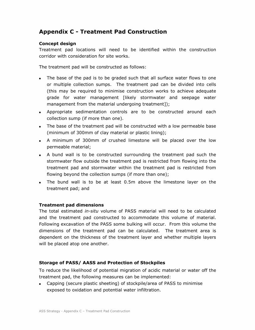
ASS Strategy - Appendix C – Treatment Pad Construction
Appendix C - Treatment Pad Construction
Concept design
Treatment pad locations will need to be identified within the construction
corridor with consideration for site works.
The treatment pad will be constructed as follows:
� The base of the pad is to be graded such that all surface water flows to one
or multiple collection sumps. The treatment pad can be divided into cells
(this may be required to minimise construction works to achieve adequate
grade for water management [likely stormwater and seepage water
management from the material undergoing treatment]);
� Appropriate sedimentation controls are to be constructed around each
collection sump (if more than one).
� The base of the treatment pad will be constructed with a low permeable base
(minimum of 300mm of clay material or plastic lining);
� A minimum of 300mm of crushed limestone will be placed over the low
permeable material;
� A bund wall is to be constructed surrounding the treatment pad such the
stormwater flow outside the treatment pad is restricted from flowing into the
treatment pad and stormwater within the treatment pad is restricted from
flowing beyond the collection sumps (if more than one);
� The bund wall is to be at least 0.5m above the limestone layer on the
treatment pad; and
Treatment pad dimensions
The total estimated in-situ volume of PASS material will need to be calculated
and the treatment pad constructed to accommodate this volume of material.
Following excavation of the PASS some bulking will occur. From this volume the
dimensions of the treatment pad can be calculated. The treatment area is
dependent on the thickness of the treatment layer and whether multiple layers
will be placed atop one another.
Storage of PASS/ AASS and Protection of Stockpiles
To reduce the likelihood of potential migration of acidic material or water off the
treatment pad, the following measures can be implemented:
� Capping (secure plastic sheeting) of stockpile/area of PASS to minimise
exposed to oxidation and potential water infiltration.

ASS Strategy - Appendix C – Treatment Pad Construction
� Construct diversion banks up-slope of stockpiles to prevent run-on water
entering the PASS/AASS storage/ bunded area.
� Establish sediment control structures to ensure the PASS material is not
eroded and transported from the storage areas to the surrounding
environment.
If dry conditions are encountered then dust controls should be implemented.

ASS Strategy - Appendix D – ASS Management and Treatment
Appendix D – ASS Management and Treatment
Estimate the potential amount of soil that may be disturbed and determine a
treatment area large enough to contain all excavated PASS or AASS. Treatment
areas shall meet the following requirements:
a) Be located at least 50m from waterways
b) Be constructed with impervious clay bunds to prevent leachate runoff
c) Be lined with agricultural lime on the floor of the treatment area.
The treatment area will require a settlement pond or sump to collect any runoff.
The pond or sump must be designed to capture the PASS treatment area runoff
a 1 in 10 year (1 hour) storm event.
Immediate Reuse
In the case of immediate reuse on site (e.g. trenching and backfilling within a
day), there is a reduced likelihood that PASS will be exposed long enough to
oxidise and become AASS. Immediate reuse (same day) may be appropriate if
PASS are of low to moderate strength. It is recommended that lime application
occur prior to backfilling as a precautionary measure.
Further, the soil material will require backfilling in the reverse order of
excavation (i.e. last out first in). Note: the majority of situations are not
conducive for immediate reuse and as such the methods of ASS management
outlined in this Plan will need to be undertaken. This decision for immediate
reuse can ONLY be made by the Environment Manager and/or Environment
Coordinator.
Treatment of PASS onsite
Soil shall be laid in 150mm to 300mm layers on a treatment pad and lime added
in accordance with the calculated liming rates. The soil shall be turned over/
mixed in a manner such that lime will be distributed throughout the soil matrix..
The treatment rate will be dependent on the analytical results and should be
calculated as outlined in the ASSMAC guidelines.
Note: Refer to laboratory results and recommendations for final dosing rates
taking into account the fineness factor of the lime and the factor of safety.
The material is then left on the treatment pad for approximately 4-5 days to
allow neutralisation to occur, turning the soils when the surface dries out, and so
increasing the rate of oxidation. Effective drying and mixing of lime with clay is
often very difficult. The drying rate is dependent on the temperature and in
cooler climates the methods may be too slow to be practicable.

ASS Strategy - Appendix D – ASS Management and Treatment
Water contained within the collection sumps will need to be sampled to assess
requirements for treatment prior to discharge.
This material shall remain bunded until validation results are available and
return concentrations less than the respective criteria. Should the stockpile
validation results exceed the criteria, additional lime will be added as required
and further validation samples collected.
Onsite storage without treatment
This method involves the placing of the PASS material on a section of the
treatment pad as per construction details provided in Appendix C. The material
is left in this area and left to oxidise and weather, naturally reducing the acidity
of the material over time. However, the PASS must go through a process of
oxidisation becoming AASS and then neutralising which can take months to fully
complete. This is only feasible if the there is time to allow this process and space
on site to construct a bunded area. The bunded area needs to remain in place
for a period of up to several months and must be subject to a regular testing
regime to monitor progress.
All water captured in the bunded area must be treated/ neutralised and tested
for compliance with the standard site criteria prior to re-use or discharge. All
discharge will be limited to the recharge basin to prevent pollution and
contamination of adjacent waterways and or drainage lines.

ASS Strategy - Appendix E – Contingency Options
Appendix E - Contingency Options
If PASS is suspected, appropriate actions must be taken to ensure the PASS is
not able to oxidise in the field. For example:
� If PASS is shown to occur in the vicinity of the work area, choose a
construction method that avoids the need to disturb PASS.
� If avoidance of PASS is not possible, notify environment staff of upcoming
works at least 5 days prior to commencement of activities.
If field test results indicate that PASS/ AASS maybe present then collect a
sample for submission to a NATA accredited Laboratory for confirmation of PASS
/ AASS and to calculate the applicable liming rate.
Separate all soil material with field results indicating possible AASS or PASS from
the remainder of the spoil and place in a section of the treatment pad (up
gradient from the material subject to treatment).
Note: Until ASS is confirmed do not stockpile with confirmed ASS. Stockpile on
impervious pad area (i.e. clay of plastic lined bunded area) separately.
Some over-excavation of ASS areas may be required to ensure all ASS is
removed due to soil and groundwater conditions making it difficult to separate
ASS from other material. Care should be undertaken when excavating ASS to
minimise the volume of soil excavated. However, some over excavation above
and below ASS layers will be required. The extent of over excavation will be
dependent on site conditions.

ASS Strategy - Appendix F – Disposal
Appendix F - Disposal
If immediate off-site disposal is required, procedures outlined within the
document Waste Classification Guidelines, Part 4: Acid Sulfate Soils (DECCW
2008) shall be implemented. This includes the following:
� Keep potential ASS wet at all times during excavation and subsequent
handling, transport and storage until they can be disposed of safely.
� ASS must be received at the proposed disposal point within 16 hours of
being dug up.
� Potential ASS may be disposed of in water below the permanent water table,
provided:
- this occurs before they have had a chance to oxidise, i.e. within 24 hours
of excavation
- they meet the definition of ‘virgin excavated natural material’ (VENM)
under the Protection of the Environment Operations Act 1997, even
though they contain sulfidic ores or soils.
� Landfills shall be licensed by DECCW to dispose of potential ASS below the
water table. DECCW’s Environment Line has details on facilities able to
accept this waste: phone 131 555.
� Potential ASS must be disposed of within 8 hours of their receipt at a landfill
and kept wet at all times until their burial at least 2 metres below the lowest
historical level of the water table at the disposal site.
� Documentation must be provided to the occupier of the landfill for each
truckload of potential ASS received, indicating that the soil’s excavation,
transport and handling have been in accordance with the Acid Sulfate Soil
Manual, thus preventing the generation of acid.
� The occupier of the disposal site must also test the pH of each load of soil
received immediately prior to its placement under water using the test
method(s) in the Acid Sulfate Soil Manual (Methods 21A and/or 21Af). These
details, together with the pH of the soil recorded at the time of its extraction,
must be retained by the occupier of the landfill site.
� The disposal site’s licence will outline what documentation needs to be kept
and for how long.
� Soil that has dried out, undergone any oxidation of its sulfidic minerals, or
which has a pH of less than 5.5 must be treated by neutralisation and
disposed of at a landfill that can lawfully accept it (see ‘Disposal of actual
acid sulfate soils’ below).
� The pH of the water at the landfill into which the potential ASS is placed
must not be less than 6.0 at any time. Landfill licence conditions require the

ASS Strategy - Appendix F – Disposal
occupiers of potential ASS disposal sites to regularly monitor the pH of
ground and surface waters at their premises.
For any transport of PASS:
� Lime the bottom of the truck;
� Load PASS and coat top layer with lime; and
� Cover spoil load.
Disposal of potential acid sulfate soils above the water table
Where PASS cannot be treated and reused on site, the soil must be treated in
accordance with the neutralising techniques in the Acid Sulfate Soil Manual. After
treatment, the soil should be sampled with chemically analysis undertaken in
general accordance with Step 5 in Part 1 of the Waste Classification Guidelines
(DECCW, 2008), available at www.environment.nsw.gov.au/waste/envguidlns.
Upon receipt of the analytical results an assessment will be undertaken to
understand the waste classification. The soil material shall then be disposed of
to a landfill that can lawfully accept that class of waste. If the soil material has
been neutralised and the analytical results return concentrations less than the
respective criteria, it can be reused on site in accordance with the Spoil and Fill
Management Sub-Plan.
Treatment of actual acid sulfate soils prior to disposal
‘AASS must be treated by the generator of the waste before it can be disposed
offsite. Treatment should be in accordance with the neutralising techniques
outlined in the Acid Sulfate Soil Manual.’1
Following neutralisation, the generator of the waste must chemically assess the
soil in accordance with Step 5 of the Waste Classification Guidelines: Part 1 –
Classifying waste (DECCW,2008) (available at
www.environment.nsw.gov.au/waste/envguidlns). A review of the analytical
results will be undertaken on a range of parameters (not AASS or PASS) that
may impact on the waste classification for offsite disposal.
Once classified, the waste must be taken to a landfill licensed to accept that
class of waste.
Prior arrangements will be made with the occupier of the landfill to ensure that it
is licensed to accept the waste. The landfill should be informed that the AASS
has been treated in accordance with the neutralising techniques outlined in the
NSW Acid Sulfate Soil Manual and that the waste has also been classified in
1 Waste Classification Guidelines, Part 4: Acid Sulfate Soils (DECCW 2008)

ASS Strategy - Appendix F – Disposal
accordance with Waste Classification Guidelines: Part 1 – Classifying waste
(DECCW,2008). A copy of the analytical results will be required by the Landfill
prior to disposal.
(Source Document: Waste Classification Guidelines, Part 4: Acid Sulfate Soils
(DECCW 2008)
If treatment has occurred, onsite re-use and/or disposal of the treated soil can
be undertaken. Testing of soil pH shall be carried out by the Environment Team
prior to reuse onsite. This material can be placed in mounds, extend batters or
used for landscaping purposes, compacted and covered with a minimum of
Appendix G
Sediment basin location and size

SWMP-Appendix G – Sediment basin location and size Page 1 of 2
Basin Schedule March 2011
BASIN
TAG BASIN TYPE Receiving Waterway CONSTRUCTION OPERATONAL DESIGN
VOLUME (m3)
VOLUME
(m3)
VOLUME
(m3)
B 13.44 R Temp-Permanent Tributary to Wallis Creek 623 1479 1475.3
B 13.76 L Temporary Tributary to Wallis Creek 641 60 664.9
B 14.20 R Temp-Permanent Wallis Creek 1470 3092 3745
B 14.26 L Temp-Permanent Wallis Creek 714 433.1 725.3
B 14.38 L Temp-Permanent Wallis Creek 975 1183.7 1540.2
B 15.40 L Temp-Permanent Eventually Joins With Swap Creek 675 918.6 537.2
B 15.84 R Temp-Permanent Swamp Creek 0 1517.8 917
B 16.36 R Temp-Permanent Tributary to Swamp Creek 1631 1268.2 1642.3
B 17.06 R Temp-Permanent Eventually Into Black Waterholes Creek 417 242 430.4
B 17.14 R Temp-Permanent Eventually Into Black Waterholes Creek 830 1135 1245
B 18.25 R Temp-Permanent Black Waterholes Creek 570 1077.7 1077.7
B 18.40 R Temp-Permanent Black Waterholes Creek 570 1754 3275
B 19.40 R Temporary Eventually Into Black Waterholes Creek 623 0 735.6
B 20.00 R Temp-Permanent Tributary of Black Waterholes Creek 220 539.8 315.6
B 20.04 R Temp-Permanent Tributary of Black Waterholes Creek 423 356 427.5
B 20.66 L Temp-Permanent Eventually Into Black Waterholes Creek 795 2257.9 2044.9
B 21.00 L Temp-Permanent Joins Lower Section Of Black Water holes Creek 1090 2294.1 2355.1
B 22.26 R Temp-Permanent Sawyers Gully Creek 491 886.8 501.6
B 22.35 R Temp-Permanent Sawyers Gully Creek 0 509.6 290.1
B 23.00 R Temp-Permanent Eventually Into Sawyers Gully Creek 887 1778.3 1507.3
B 23.51 R Temp-Permanent Eventually Into Sawyers Gully Creek 591 1578.6 725.3
B 23.68 R Temp-Permanent Eventually Into Bishops Creek 1071 1336.9 1392.1
B 24.45 R Temp-Permanent Bishops Creek 431 404.4 449.3
B 24.66 L Temp-Permanent Bishops Creek 830 498.6 834.5
B 25.02 L Temp-Permanent Bishops Creek 2111 1647.2 2175.5
B 26.06 L Temp-Permanent Eventually Into Bishops Creek 101 259.6 309.5
B 26.15 L Temp-Permanent Eventually Into Bishops Creek 0 384.3 431.9
B 26.33 L Temp-Permanent Eventually Into Bishops Creek 0 600 605.9
B 26.62 L Temp-Permanent Eventually Into Bishops Creek 1298 1736 1767.5
B 27.10 L Temp-Permanent Unnamed Creek 0 750 753.6
B 27.20 R Temp-Permanent Unnamed Creek 300 400 423.9
B 27.22 L Temp-Permanent Unnamed Creek 493 1650 1772.9
B 28.23 R Temp-Permanent Unnamed Creek 798 1100 1117.3
B 28.35 R Temp-Permanent Unnamed Creek 220 975 984.6
B 28.68 R Temp-Permanent Unnamed Creek 407 626.6 353
B 29.21 R Temp-Permanent Unnamed Creek 389 605.6 393.6
B 29.43 R Temp-Permanent Unnamed Creek 600 681.5 622.9
B 29.79 R Temp-Permanent Unnamed Creek 344 526.5 754.4
B 30.20 R Temp-Permanent Unnamed Creek 261 225 231.6
B 30.82 R Temp-Permanent Eventually Into Sawyers Creek 960 960 1007.6
B 30.94 R Permanent Eventually Into Sawyers Creek 0 375 396.2
B 31.78 R Temp-Permanent Eventually Into Sawyers Creek 1207 1100 1117.3
B 32.17 R Temp-Permanent Eventually Into Sawyers Creek 804 1100 1141.3
B 32.49 R Temp-Permanent Sawyers Creek 395 1150 1245
B 32.60 L Temp-Permanent Sawyers Creek 1180 595 598.9
B 34.04 R Temp-Permanent Tributary of Anvil Creek 891 1814.8 927.3
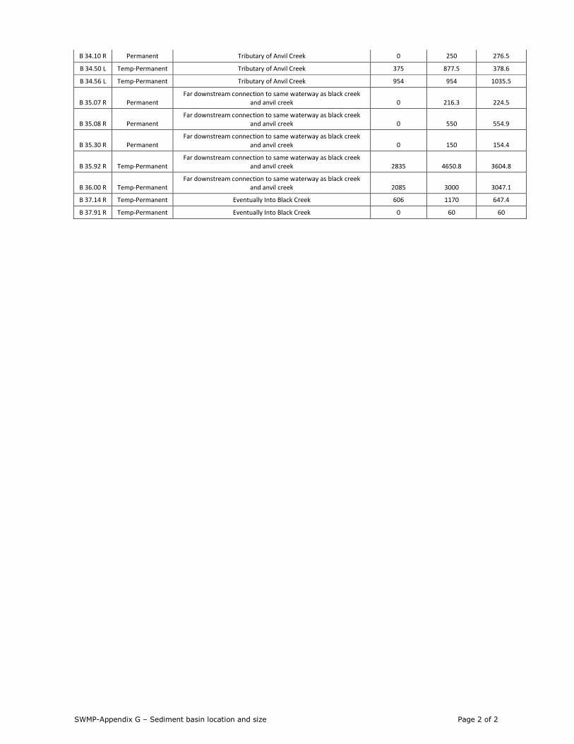
SWMP-Appendix G – Sediment basin location and size Page 2 of 2
B 34.10 R Permanent Tributary of Anvil Creek 0 250 276.5
B 34.50 L Temp-Permanent Tributary of Anvil Creek 375 877.5 378.6
B 34.56 L Temp-Permanent Tributary of Anvil Creek 954 954 1035.5
B 35.07 R Permanent
Far downstream connection to same waterway as black creek
and anvil creek 0 216.3 224.5
B 35.08 R Permanent
Far downstream connection to same waterway as black creek
and anvil creek 0 550 554.9
B 35.30 R Permanent
Far downstream connection to same waterway as black creek
and anvil creek 0 150 154.4
B 35.92 R Temp-Permanent
Far downstream connection to same waterway as black creek
and anvil creek 2835 4650.8 3604.8
B 36.00 R Temp-Permanent
Far downstream connection to same waterway as black creek
and anvil creek 2085 3000 3047.1
B 37.14 R Temp-Permanent Eventually Into Black Creek 606 1170 647.4
B 37.91 R Temp-Permanent Eventually Into Black Creek 0 60 60