stability of cold-formed elements - cvut.czsteel.fsv.cvut.cz/suscos/pp/2e12-05-stability of...
TRANSCRIPT

STABILITY OF COLD-FORMED ELEMENTSCzech Technical University in Prague
2E12 Design of steel structures for renewable energy systems 1
21/11/2010

Contents
21/11/20102E12 Design of steel structures for renewable energy systems
2
Behavior features: local buckling of compression elements plane elements elements with stiffeners
shear lag web crippling
Cross-section check Beams restrained by sheeting Connections

Cross-section idealiseation
21/11/2010
3
C9 Design of steel structures for renewable energy systems

Cross-section
21/11/2010C9 Design of steel structures for renewable energy systems
4
Idealised section with radiuses r=0 when r<5t

Buckling in compression
21/11/2010
5
C9 Design of steel structures for renewable energy systems

Buckling strength
21/11/2010C9 Design of steel structures for renewable energy systems
6
Local buckling Distortional buckling
Section distortion
Global buckling Shear buckling
Sectional modes

Buckling strength
21/11/2010C9 Design of steel structures for renewable energy systems
7

Buckling strength
21/11/2010C9 Design of steel structures for renewable energy systems
8

Local buckling
21/11/2010C9 Design of steel structures for renewable energy systems
9
Theory + calculation procedures (see local buckling of plates)
Elements: doubly supported outstands
stiffened plain
1,052com comp
cr
bt k Eσ
σ σλ
σ= = com yfσ ≤

Stiffeners
21/11/2010C9 Design of steel structures for renewable energy systems
10
Edge stiffeners
Intermediate stiffeners

Stress distribution on stiffened plate
21/11/2010C9 Design of steel structures for renewable energy systems
11
Calculation model stiffener supports plane element stiffener itself can buckle (as compression member on
elastic foundation)

Buckling of edge stiffener
21/11/2010C9 Design of steel structures for renewable energy systems
12
Vran
y

Spring stiffness of stiffener
21/11/2010C9 Design of steel structures for renewable energy systems
13

Stress distribution - idealisation
21/11/2010C9 Design of steel structures for renewable energy systems
14
- distortional buckling

Calculation procedure
21/11/2010C9 Design of steel structures for renewable energy systems
15
1. Stiffener provides rigid support to the plate ⇒effective widths
2. K, As, Is3. Critical stress σcr4. for σcom = fy ⇒ χd (distortional buckling)5. σcom = χd fy6. Effective widths of parts adjacent to the stiffener7. As, Is8. iteration 3. – 7.9. tred = χd t

Final effective cross-section
21/11/2010C9 Design of steel structures for renewable energy systems
16
, 2 , 1e i e ib b≥
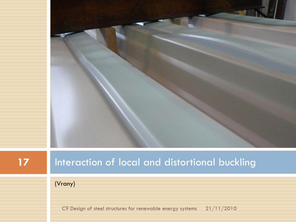
(Vrany)
Interaction of local and distortional buckling
21/11/2010
17
C9 Design of steel structures for renewable energy systems
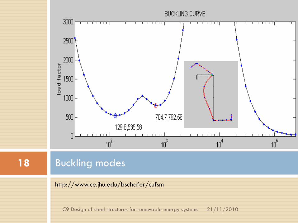
http://www.ce.jhu.edu/bschafer/cufsm
Buckling modes
21/11/2010
18
C9 Design of steel structures for renewable energy systems

Check – cross-sections, members
21/11/2010C9 Design of steel structures for renewable energy systems
19
EN 1993-1-3
Limits: members0,45 ≤ t ≤ 15 mm sheeting 0,45 ≤ t ≤ 4 mm

Compression
21/11/2010C9 Design of steel structures for renewable energy systems
20
interaction of local and global buckling
=> χ
. 1b Rd eff y MN A fχ γ=
1
eff y effR
cr g cr g
A f ANN A A
λλσ λ
= = =
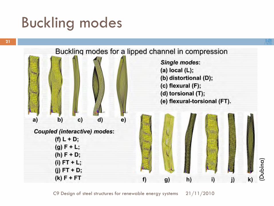
Buckling modes
21/11/2010C9 Design of steel structures for renewable energy systems
21
(Dub
ina)

Flexural-torsional buckling
21/11/2010C9 Design of steel structures for renewable energy systems
22
uniaxial symmetrical profiles
torsional buckling: flexural-torsional buckling: …combination
buckling curve b
2w
cr,T t2 2g o T
1 EIGIA i
πσ
= +
cr,TFσ cr,T cr,, yσ σ
( )22cr,y y yE iσ π=

Members subjected to bending
21/11/2010
23
C9 Design of steel structures for renewable energy systems

Bending
21/11/2010C9 Design of steel structures for renewable energy systems
24
Lateral-torsional buckling
Specific design of cold-formed members in bending subjected to lateral-torsional buckling
( ).eff Rd LT eff ydM W fχ=

Behaviour - Z section in bending
21/11/2010C9 Design of steel structures for renewable energy systems
25
Slender section → local buckling Edge stiffener – distortional buckling
Non-symmetry → distortion of cross-section Out-of-plane buckling of free flange in hogging moment areas

Cross-section distortion
21/11/2010C9 Design of steel structures for renewable energy systems
26
C D
+
--
++
-
++
--
Reality Idealized model

Cross-section distortion
21/11/2010C9 Design of steel structures for renewable energy systems
27
Simplified model
K
C D
+=
y
z
y
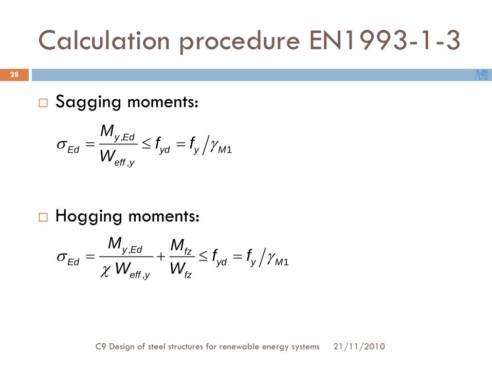
Calculation procedure EN1993-1-3
21/11/2010C9 Design of steel structures for renewable energy systems
28
Sagging moments:
Hogging moments:
,1
,
y EdEd yd y M
eff y
Mf f
Wσ γ= ≤ =
,1
,
y Ed fzEd yd y M
eff y fz
M M f fW W
σ γχ
= + ≤ =

Web crippling
21/11/2010
29
C9 Design of steel structures for renewable energy systems

(Vrany)
Web crippling
21/11/2010
30
C9 Design of steel structures for renewable energy systems

(Vrany)
Web crippling
21/11/2010
31
C9 Design of steel structures for renewable energy systems

Web crippling
21/11/2010C9 Design of steel structures for renewable energy systems
32
Eccentric compression to web Rw,Rd …equations derived experimentally

Web crippling
21/11/2010C9 Design of steel structures for renewable energy systems
33
Cases: Single web
Two or more webs

Web crippling
21/11/2010C9 Design of steel structures for renewable energy systems
34
Loading – cases: a) close to free end b) far from free end
a) from one side b) from both opposite sides
Rw,Rd = f(t2, r/t, f, ss …) product of individual factors

Interaction
21/11/2010
35
C9 Design of steel structures for renewable energy systems
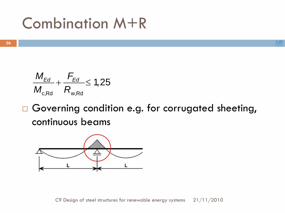
Combination M+R
21/11/2010C9 Design of steel structures for renewable energy systems
36
Governing condition e.g. for corrugated sheeting, continuous beams
c,Rd w,Rd
1,25Ed EdM FM R
+ ≤

Combination compression + bending
21/11/2010C9 Design of steel structures for renewable energy systems
37
,E d E d ,z N yM N e∆ =

Shear lag
21/11/2010
38
C9 Design of steel structures for renewable energy systems

Shear lag
21/11/2010Thin walled and composite structures / Michal Jandera /
39
by elastic analysis (I. order) ⇒ both tension and compression
factor of ratio Le/b0 … to solve when Le/b0 < 50

Shear lag
21/11/2010Thin walled and composite structures / Michal Jandera /
40
for thin-walled sections, b0:
Effective width:
( )0
max
b
eff
y dyb
σ
σ=∫

Shear lag
21/11/2010Thin walled and composite structures / Michal Jandera /
41
Effective width: Effective width factor
0effb bβ= ⋅

Connections
21/11/2010
42
C9 Design of steel structures for renewable energy systems

Connections
21/11/2010C9 Design of steel structures for renewable energy systems
43
Welds fillet t ≥ 3 mm (automatic … t ≥ 2 mm)MAG is best lap connections
spot

Connections
21/11/2010C9 Design of steel structures for renewable energy systems
44
Mechanical fasteners blind rivets screws 3 ≤ d ≤ 8 mm self-drilling (self-tapping) thread-cutting
cartridge fired pins bolts

Blind rivets
21/11/2010C9 Design of steel structures for renewable energy systems
45
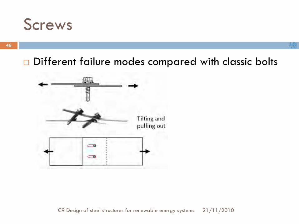
Screws
21/11/2010C9 Design of steel structures for renewable energy systems
46
Different failure modes compared with classic bolts

New types of connections
21/11/2010C9 Design of steel structures for renewable energy systems
47
“Rossete” system
Adhesive bonding (problem of lifespan reliability)

Design aids
21/11/2010
48
C9 Design of steel structures for renewable energy systems

Design aids
21/11/2010C9 Design of steel structures for renewable energy systems
49
Tables
PROFIL
váha profilu řádek rozpětí pole L [m] rozpětí pole L [m]číslo 5,0 6,0 7,0 8,0 9,0 10,0 5,0 6,0 7,0 8,0 9,0 10,0
1 3,41 2,34 1,70 1,29 1,00 4,91 3,03 2,09 1,54 1,192 3,41 2,34 1,70 1,15 4,91 3,03 2,09 1,54 1,19
Z 250/2,0 3 3,28 1,86 1,15 4,91 3,03 2,09 1,48 1,027,80 kg/m 4 2,49 1,63 1,12 3,95 2,48 1,70 1,25
5 -2,44 -1,65 -1,19 -0,89 -0,69 -3,95 -2,64 -1,90 -1,43 -1,116 -1,92 -1,29 -0,91 -0,68 -0,52 -3,16 -2,08 -1,48 -1,10 -0,851 4,61 3,17 2,31 1,74 1,36 1,08 6,59 4,10 2,84 2,11 1,64 1,302 4,61 3,17 2,28 1,50 1,02 6,59 4,10 2,84 2,11 1,64 1,30
Z 250/2,5 3 4,25 2,42 1,49 0,97 6,59 4,10 2,84 1,92 1,329,70 kg/m 4 3,66 2,43 1,68 1,20 5,75 3,57 2,47 1,83 1,41 1,03
5 -3,31 -2,26 -1,63 -1,22 -0,95 -0,75 -5,29 -3,58 -2,59 -1,95 -1,52 -1,216 -2,81 -1,91 -1,37 -1,02 -0,78 -0,62 -4,53 -3,04 -2,19 -1,64 -1,27 -1,01
PROSTÝ NOSNÍK SPOJITÝ NOSNÍK S PŘESAHY

Design aids
21/11/20102E12 Design of steel structures for renewable energy systems
50
Software