flexural-torsional buckling of general cold … of the annual stability conference structural...
TRANSCRIPT

Proceedings of the Annual Stability Conference
Structural Stability Research Council San Antonio, Texas, March 21-24, 2017
Flexural-Torsional Buckling of General Cold-Formed Steel Columns with Unequal Unbraced Lengths
Robert S. Glauz, P.E.1
Abstract The design of cold-formed steel columns must consider flexural buckling, torsional buckling, and flexural-torsional buckling. The American Iron and Steel Institute incorporated equations for the critical elastic buckling loads corresponding to these failure modes in the North American Specification for the Design of Cold-Formed Steel Members. These equations were originally developed for columns with consistent boundary conditions for all three modes. However it is common in practice to have different unbraced lengths for major axis flexure, minor axis flexure, and torsion. Furthermore, it is common for certain members to be oriented such that intermediate bracing restraint directions do not align with the principal axes. This paper investigates and develops a general formulation of the column buckling equation to incorporate unequal unbraced lengths and non-principal axes. 1. Introduction Cold-formed steel structural members are often used in framing configurations where intermediate bracing provides a reduced unbraced length for one direction and twisting. A common example is a Zee purlin as shown in Figure 1. Since a Zee shape is point-symmetric with the shear center coinciding with the centroid, there is no interaction between torsional buckling and flexural buckling. Therefore the buckling limit is simply the smaller of the two buckling loads.
Figure 1. Typical bracing configuration where unbraced lengths are different
1 President/Owner, RSG Software, Inc., [email protected]
Lx
Ly=L t

2
The flexural buckling load is normally calculated using the conventional � = ���� ��⁄ , where I is the minor principal axis moment of inertia. But since the bracing directions do not coincide with the principal axes, the impact of having different unbraced lengths is not evident. The coupling of the two flexural modes requires further investigation. Similarly, a singly-symmetric Cee shape is commonly used with intermediate bracing to reduce the unbraced length for minor axis buckling and torsional buckling. Since the shear center for a Cee shape does not coincide with the centroid, interaction between flexural buckling and torsional buckling occurs. The unbraced lengths for flexure and torsion can be different, therefore complicating the interaction between them. The column buckling equations used in cold-formed steel design today were investigated by Timoshenko (1961) and others. They were further studied by Winter and Chajes (1965) for development of the design criteria in the AISI Specification. These buckling equations were developed using principal axes and equal unbraced lengths for all modes. This paper expands on their excellent work to consider the more general case of unequal unbraced lengths and non-principal axes. Numerous symbols are used in this investigation which are defined Section 9. 2. Flexural-Torsional Buckling The development of the critical buckling load for a general cold-formed steel shape must consider a combination of flexural buckling and torsional buckling. Figure 2 represents an arbitrary non-symmetric cross section oriented to centroidal x and y axes which represent the two orthogonal directions of translational bracing. These axes need not be the principal axes.
Figure 2. Arbitrary cross-section oriented to x and y bracing directions
The application of axial load P at the centroid C with sufficient magnitude will produce buckling where the cross-section displaces u and v in the x and y directions, and rotates about its shear center
O v
yo
C
y
x
u xo O1
C1
C2
φ
+My
+Mx

3
by angle φ. The centroid translates from C to C1, and the shear center translates from O to O1. The rotation causes the centroid to move to its final position C2. To maintain equilibrium, the displaced cross-section develops moments about the x and y axes, which are the product of the axial load P and the x and y displacements from C to C2, as shown in Eqs. 1 and 2. �� = −�� − ��� (1) �� = −�� + ���� (2) The stiffness relationship between moment and deflection for non-principal axes must consider unsymmetrical bending. The general form of this relationship is a pair of differential equations (Eqs. 3 and 4) as developed by Timoshenko (1961, p. 242) and others, which involves the product of inertia Ixy. Equating these to the moments defined by the buckling equilibrium relationships (Eqs. 1 and 2) provides two differential equations with three unknowns: u, v, and φ. �� = ����� + ���� �� = −�� − ��� (3) �� = ��� �� + ������ = −�� + ���� (4) A third relationship is required involving torsion, which was investigated by Timoshenko (1961, p. 231). Similar to the flexure equations, the stiffness relationship is equated to the buckling equilibrium relationship, both in terms of the torsion per unit length Tz, as shown in Eq. 5. Although this torsion development was presented using principal x and y axes, no assumptions were made that required principal axes. This relationship is applicable to any section orientation. �� = �������� − ����� = ����� − �� ��� − ������� (5) The solution to these three simultaneous differential equations is developed here using a pinned end column of length L, and subsequently generalized for other cases. Thus we will assign the following boundary conditions: = = � = 0 at z = 0 and z = L �� = �� = ��� = 0 at z = 0 and z = L The solution for u, v, and φ are therefore in the forms shown in Eq. 6. The first buckling mode corresponds to one half-wavelength, where n1 = n2 = n3 = 1. To accommodate different unbraced lengths, greater values of n may be used to produce unbraced lengths of L/n, and the nodes where the displacements are zero would correspond to the brace points. = �� sin
��
� = �� sin
��
� � = �� sin
��
� (6)
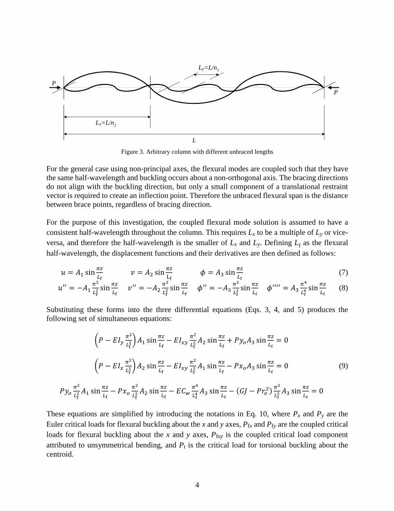
As illustrated in Figure 3, we will let Ly = L/n1, Lx = L/n2, and Lt = L/n3. It should be noted that any set of unbraced lengths can be accommodated mathematically by defining an imaginary column whose length is a common multiple of the three unbraced lengths, or L = LCM(Lx, Ly, Lt).
4
Figure 3. Arbitrary column with different unbraced lengths
For the general case using non-principal axes, the flexural modes are coupled such that they have the same half-wavelength and buckling occurs about a non-orthogonal axis. The bracing directions do not align with the buckling direction, but only a small component of a translational restraint vector is required to create an inflection point. Therefore the unbraced flexural span is the distance between brace points, regardless of bracing direction. For the purpose of this investigation, the coupled flexural mode solution is assumed to have a consistent half-wavelength throughout the column. This requires Lx to be a multiple of Ly or vice-versa, and therefore the half-wavelength is the smaller of Lx and Ly. Defining Lf as the flexural half-wavelength, the displacement functions and their derivatives are then defined as follows: = �� sin
�
�� = �� sin
�
� � = �� sin
�
�� (7)
�� = −���
��� sin
�
�� �� = −��
�
��� sin
�
�� ��� = −��
�
��� sin
�
�� ����� = ��
�
��� sin
�
�� (8)
Substituting these forms into the three differential equations (Eqs. 3, 4, and 5) produces the following set of simultaneous equations:
�� − ��� �
������ sin
�
��− ���� �
��� �� sin
�
��+ ����� sin
�
��= 0
�� − ��� �
������ sin
�
��− ���� �
��� �� sin
�
��− ���� sin
�
��= 0 (9)
��� �
��� �� sin
�
��− �� �
��� �� sin
�
��− ��� �
��� �� sin
�
��− ��� − ����� �
��� �� sin
�
��= 0
These equations are simplified by introducing the notations in Eq. 10, where Px and Py are the Euler critical loads for flexural buckling about the x and y axes, Pfx and Pfy are the coupled critical loads for flexural buckling about the x and y axes, Pfxy is the coupled critical load component attributed to unsymmetrical bending, and Pt is the critical load for torsional buckling about the centroid.
P P
L
Ly=L/n1
Lx=L/n2

5
�� =������� �� =
������� �� = �
�� ��� + ��� �
����
��� =������� = �� ���
��� ��� =
������� = �� ���
��� ���� =
�������� (10)
Substituting the terms defined in Eqs. 7 and 10 into Eqs. 9, and multiplying the terms in the third equation by ��� ��⁄ , produces the following system of equations:
������� − ��� −���� ���−���� � − ��� −����� ��
�
��� −�� ��
�
��� �� − ���������
���
� ! "
� $ % &=
� ! "0
0
0 $ % &
(11)
The solution where all displacements are zero is not of interest, therefore the determinant of the coefficients must be equal to zero. Expansion of this determinant gives the general form of the column buckling characteristic equation:
(� − ���)(� − ���)(� − ��) − �� ��
��
���
��� (� − ���) − �� ��
��
���
��� (� − ���)
+2�� ����
���
��� ���� − �� − �������� = 0 (12)
As a cubic equation, there are three possible root values for P. Inserting the lowest positive root in Eq. 11 establishes the relative magnitudes of the displacement functions u, v, and φ for the controlling mode. Another buckling mode is possible where the flexural buckling direction is associated with the larger unbraced length, with no displacement in the perpendicular direction. For buckling about the x axis, the displacement functions are as follows: = 0 = �� sin
�
�� � = �� sin
�
�� (13)
�� = 0 �� = −���
��� sin
�
�� ��� = −��
�
��� sin
�
�� ����� = ��
�
��� sin
�
�� (14)
This reduces the system of equations to:
' � − �� −��−�� ��
�
��� �� − ������( )
�
* = )0
0
* (15)
Expansion of the determinant results in the following additional equation:

6
(� − ��)(� − ��) − �� ��
��
���
��� = 0 (16)
Similarly for buckling about the y axis:
(� − ��)(� − ��) − �� ��
��
���
��� = 0 (17)
3. Specific Cases Principal Axes If the column bracing directions align with the principal axes, the product of inertia Ixy is zero. Therefore the terms in the general buckling equation containing Pfxy drop out, reducing it to:
(� − ���)(� − ���)(� − ��) − �� ��
��
���
��� (� − ���) − �� ��
��
���
��� (� − ���) = 0 (18)
The solution must also consider the orthogonal cases. The controlling roots of Eqs. 16 and 17 are given by the following quadratic solutions:
� =�
��+��� + ��� −,��� + ���� − 4-����. where - = 1 −
��
��
���
��� (19)
� =�
��+(�� + ��) −,(�� + ��)� − 4/����. where / = 1 −
��
��
���
��� (20)
For the case where β = 0, Eq. 16 becomes � = ���� ��� + ���⁄ . For the case where γ = 0, Eq. 17 becomes � = ���� (�� + ��)⁄ . If β or γ is less than zero, one root is negative but Eqs. 19 and 20 provide the positive root. Equal Unbraced Lengths If all the unbraced lengths are equal (Lx = Ly = Lf = Lt), the buckling loads Pfx and Pfy can be replaced by Px and Py, and the general buckling equation is reduced as shown in Eq. 21. There is no need to use Eqs. 19 and 20 because Eq. 21 considers all modes. This form is applicable to any orientation of x and y axes, including principal axes where Pfxy is 0. So it may be more convenient to use the principal axes properties.
(� − ��)(� − ��)(� − ��) − �� ��
�� (� − ��) − �� ��
�� (� − ��)
+2�� ���� ���� − �� − �������� = 0 (21)
Principal Axes, Equal Unbraced Lengths The equal unbraced length case above is simplified further using principal axes. The terms containing Pfxy drop out, reducing Eq. 21 to Eq. 22. This is equivalent to the Timoshenko (1961) equation.

7
(� − ��)(� − ��)(� − ��) − �� ��
�� (� − ��) − �� ��
�� (� − ��) = 0 (22)
Point-Symmetric The shear center for a point-symmetric section, such as a Zee shape, coincides with the centroid (i.e., xo = 0, yo = 0). This removes three terms from the general buckling equation, reducing it to: (� − ���)(� − ���)(� − ��) − (� − ��)����� = 0 (23) One root is obtained by setting (P – Pt) = 0, or P = Pt. The other two roots are obtained from the solution to the remaining quadratic equation:
� =�
�0��� + ���1± �
�2(��� − ���)� + 4����� (24)
Factoring Eq. 24 for the lower root reveals that buckling occurs about the minor principal axis:
� =��
��� 3�� 0�� + ��1− �
�,(�� − ��)� + 4���� 4 = ����
��� (25)
The orthogonal cases shown in Eqs. 16 and 17 must also be considered as potential controlling cases. Since the shear center coordinates are zero, these equations reduce to roots Px, Py, and Pt. Singly-Symmetric The shear center for a singly-symmetric section, such as a Cee shape, lies on the axis of symmetry. If this axis is the x axis, the properties Ixy and yo are zero. This removes three terms from the general buckling equation, reducing it to:
(� − ���)(� − ���)(� − ��) − �� ��
��
���
��� (� − ���) = 0 (26)
One root is obtained by setting (P – Pfy) = 0, or P = Pfy. Since the flexural roots are uncoupled, Pfx and Pfy can be replaced by Px and Py, so the controlling case is the smaller of Py and Eq. 19. Doubly-Symmetric For a doubly-symmetric section, the shear center coincides with the centroid as in the point-symmetric case (xo = yo = 0), and if the bracing directions align with the principal axes, Ixy = 0 and Pfxy = 0. The flexural modes are uncoupled and the buckling equation reduces to the simple form in Eq. 27, where the controlling buckling load is the smallest of Px, Py, and Pt. (� − ��)(� − ��)(� − ��) = 0 (27) Fully Braced Against Twisting It is difficult to restrain a column against twisting without also restraining translation. But for a section with high torsional stiffness, the torsional buckling mode can be disregarded. This is

8
accomplished by setting Lt = 0 in Eq. 12, thus removing three of the terms. Then factoring out the irrelevant root (P – Pt) produces Eq. 28, which is the same as the point-symmetric solution. (� − ���)(� − ���) − ����� = 0 (28) Fully Braced Against Translation If a column is fully braced in one direction, Lf approaches zero. Eq. 12 can be adapted to this case by multiplying each term by ��� ������⁄ and dropping the resulting occurrences of PLf
2. The solution is reduced to Eq. 29 which represents torsional buckling about the shear center. For the case where translation of the centroid is restrained, or where the shear center coincides with the centroid, the solution is simply P = Pt.
����� �� + ��
�� �� + 2
���� ������ +
��
��� (���� − ���� )�� − ��� = 0 (29)
For buckling perpendicular to the bracing direction, Eq. 19 or 20 should be used as applicable. If the column is also fully braced against twisting, Eq. 19 or 20 controls and the buckling load resolves to Px or Py as applicable. If the shear center is restrained in both the x and y directions, Eq. 29 provides the controlling torsional buckling load. Other Boundary Conditions The development of Eq. 12 used pinned end boundary conditions, with the displacement solutions in the basic sine forms shown in Eq. 6. However, the general form of the displacement solution to the differential equations is: 5� sin �
�+ 6� cos �
� (30)
Through trigonometric relationships, this form can be represented by a shifted sine function as shown in Eq. 31. Therefore other boundary conditions can be accommodated with the same solution by simply shifting the z position by zo along the same multi-wavelength column.
5� sin �
�+ 6� cos �
�= �� sin
�����
� (31)
where �� = 25�� + 6�� 7� =�
tan�� �
�
Effective length factors are used for various boundary conditions to establish equivalent lengths which correspond to the half-wavelength of the buckled shape. The development of Eq. 12 used general half-wavelengths of L/n. The effective length factor K can be accommodated by using a different number of half-wavelengths n', such that 8� 9�⁄ = � 9⁄ , or 9� = 89. Therefore, KxLx, KyLy, and KtLt can be used in place of Lx, Ly, and Lt, respectively. However, the assumption for coupled flexural buckling still requires KxLx to be a multiple of KyLy, or vice-versa.

9
4. Alternate Forms To facilitate either direct or iterative solutions, the general buckling equation (Eq. 12) can be rearranged into a cubic polynomial form as:
�1 −��
��
���
��� −
��
��
���
������ − :��� �1 −
��
��
���
����+ ��� �1 −
��
��
���
����+ �� − 2���� ��
��
���
���; ��
+0������ + ����� + ����� − ����� 1� − 0������ − ����� 1�� = 0 (32) This and all of the preceding buckling equations are stated in terms of axial compressive forces. These can be restated using compressive stresses, where axial stress < = � �⁄ .
<�� =��
��� ��⁄ �� <�� =
��
��� ��⁄ � <� = �
!�� ��� + ��� �
����
<�� =��
��� ��⁄ ��= <�� ���
��� <�� =
��
��� ��⁄ � = <�� ���
��� <��� =
�����!��
� (33)
The general buckling equation (Eq. 12) is provided here using stresses:
(< − <��)(< − <��)(< − <�) − <� ��
��
���
��� (< − <��) − <� ��
��
���
��� (< − <��)
+2<� ����
���
��� <��� − (< − <�)<���� = 0 (34)
Or in the cubic polynomial form as:
�1 −��
��
���
��� −
��
��
���
����<� − :<�� �1 −
��
��
���
����+ <�� �1 −
��
��
���
����+ <� − 2<��� ��
��
���
���; <�
+0<��<�� + <��<� + <��<� − <���� 1< − 0<��<�� − <���� 1<� = 0 (35) Dividing Eq. 35 by <��<��<� and introducing notations for the dimensionless coefficients results in another useful form containing stress ratios which sum to 1:
�����������
������� �
��������−
���
�����−
���
�����−
��������
������+
�
���+
�
���+
�
��= 1 (36)
where = = 1 −��
��
���
��� −
��
��
���
��� - = 1 −
��
��
���
��� / = 1 −
��
��
���
��� > =
����
���
���
The orthogonal buckling cases take the following form:
< =�
��+�<�� + <��−,�<�� + <��� − 4-<��<�. where - = 1 −
��
��
���
��� (37)
< =�
��+(<�� + <�) −,(<�� + <�)� − 4/<����. where / = 1 −
��
��
���
��� (38)
10
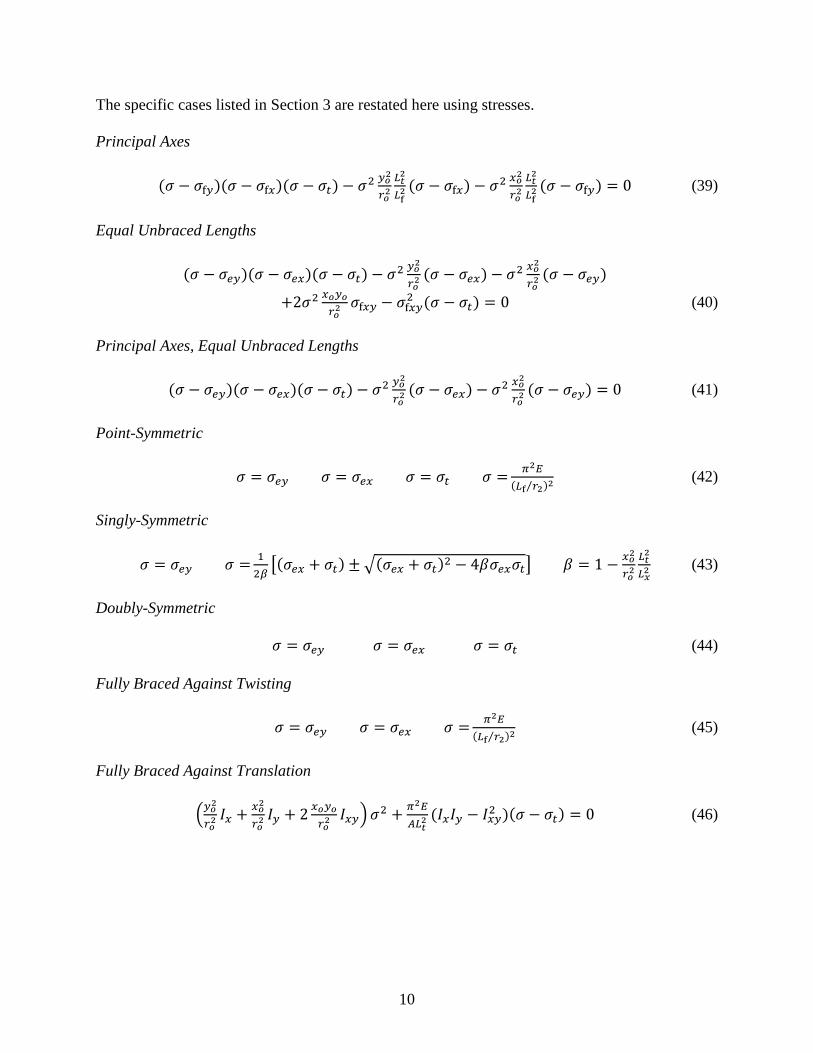
The specific cases listed in Section 3 are restated here using stresses. Principal Axes
(< − <��)(< − <��)(< − <�) − <� ��
��
���
��� (< − <��) − <� ��
��
���
��� (< − <��) = 0 (39)
Equal Unbraced Lengths
(< − <��)(< − <��)(< − <�) − <� ��
�� (< − <��) − <� ��
�� (< − <��)
+2<� ���� <��� − <���� (< − <�) = 0 (40)
Principal Axes, Equal Unbraced Lengths
(< − <��)(< − <��)(< − <�) − <� ��
�� (< − <��) − <� ��
�� (< − <��) = 0 (41)
Point-Symmetric
< = <�� < = <�� < = <� < =��
��� ��⁄ �� (42)
Singly-Symmetric
< = <�� < =�
��+�<�� + <��±,�<�� + <��� − 4-<��<�. - = 1 −
��
��
���
��� (43)
Doubly-Symmetric < = <�� < = <�� < = <� (44) Fully Braced Against Twisting
< = <�� < = <�� < =��
��� ��⁄ �� (45)
Fully Braced Against Translation
����� �� + ��
�� �� + 2
���� ����<� +
��
!��� (���� − ���� )�< − <�� = 0 (46)

11
5. Numerical Analysis Several finite element analyses were performed to compare with the predicted elastic buckling stresses. For flexural modes and torsional modes, agreement was very good as expected. But for combined flexural-torsional modes, it was observed that the torsional displacements did not follow the anticipated waveform. When flexural and torsional buckling occur together, the direction of flexure dictates the direction of rotation such that the centroid always moves away from the neutral position in the same direction as flexure. For cases where Lt is less than Lf, Figure 4 illustrates that the torsional waveform exhibits additional curvature, where the rotation between brace points occurs in only one direction, with opposite curvature at the brace points within the flexural span.
Figure 4. Flexural-torsional buckling with Lt < Lf
Whether brace points occur at mid-point, third-points, quarter-points, or more, the first and last torsional spans behave as pinned-fixed segments where the theoretical effective length factor is about 0.7. Therefore it is appropriate to multiply Lt by 0.7 for flexural-torsional cases where Lt is less than Lf. For cases where the Lt is greater than Lf, the direction of flexure dictates the direction of rotation in the same manner. Therefore the half-wavelength for torsion matches the half-wavelength for flexure, so Lt should be set equal to Lf. But for the pure torsional mode (Eqs. 42, 44, 46), σt should not use a reduced Lt. Figure 5 compares the flexural-torsional buckling stresses for an example Cee shape. The solid curves are based on Eq. 37 with the adjustments to Lt described above. The plotted finite element results (x) were very close for all cases. The current AISI provisions match for cases with equal unbraced lengths. But for all other cases, the AISI buckling stresses are much lower and very conservative.
Lf
Lt Lt

12
Figure 5. Flexural-torsional buckling stress for C4x1.5x0.5
6. Impact on Design The equations developed in this investigation differ from those used in the AISI Specification, specifically for cases where the unbraced lengths are unequal. For a point-symmetric section, such as a Zee shape, AISI specifies the critical elastic buckling stress as the lesser of �� and ��� ��� �⁄ �⁄ for minor principal axis buckling. This development confirms these calculations, and clarifies that KL should be the smaller of the two flexural effective lengths. However, the larger effective length must also be checked for buckling about its corresponding axis.
Figure 6. Flexural buckling stress for point-symmetric section with unequal unbraced lengths
13
Figure 6 shows the flexural buckling stress for a typical Zee section. The ratio �� ��⁄ for this section is 3.5, so if the ratio �� ��⁄ exceeds 3.5 the controlling flexural buckling mode is about the x axis. For the majority of common Zee shapes, columns with minor axis bracing at quarter points or closer need to be checked for buckling about the major axis. For a singly-symmetric section, the AISI elastic buckling equation is equivalent to Eq. 43, except that the coefficient β must account for cases where �� ��. If Lt is less than Lx, the effect of the shear center offset is reduced and the resulting buckling stress is higher. If Lt is greater than Lx, Lt should be taken as Lx and the resulting buckling stress is higher.
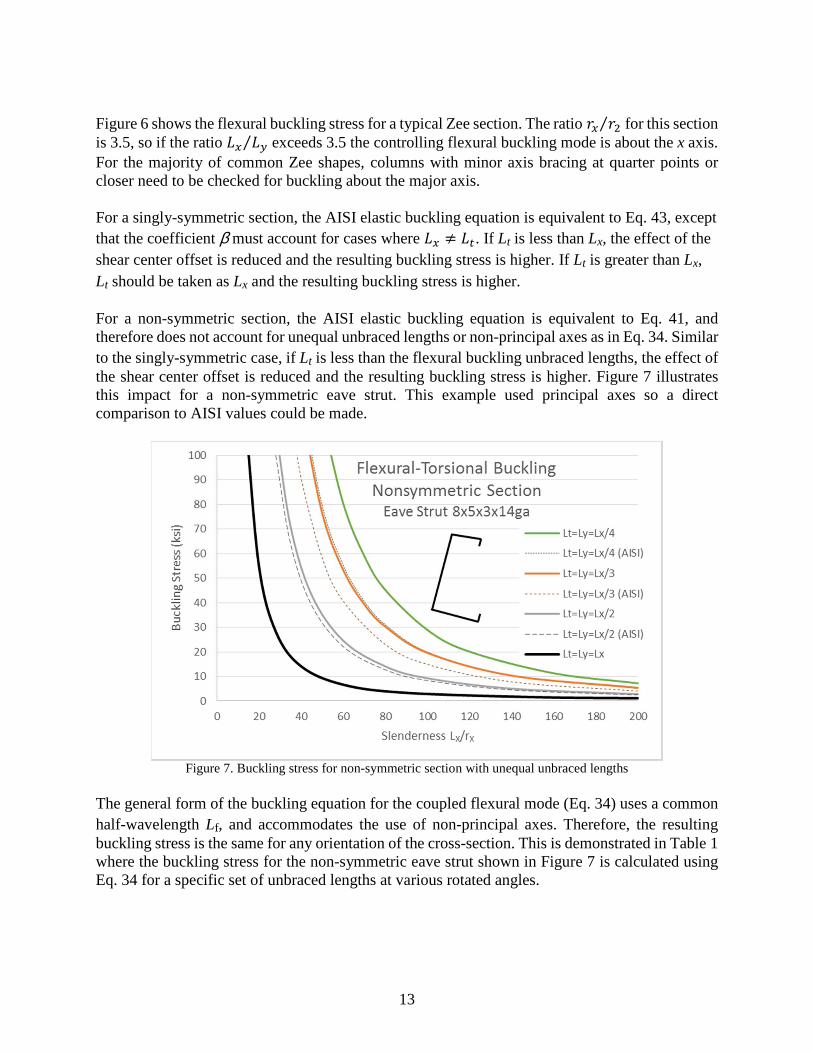
For a non-symmetric section, the AISI elastic buckling equation is equivalent to Eq. 41, and therefore does not account for unequal unbraced lengths or non-principal axes as in Eq. 34. Similar to the singly-symmetric case, if Lt is less than the flexural buckling unbraced lengths, the effect of the shear center offset is reduced and the resulting buckling stress is higher. Figure 7 illustrates this impact for a non-symmetric eave strut. This example used principal axes so a direct comparison to AISI values could be made.
Figure 7. Buckling stress for non-symmetric section with unequal unbraced lengths
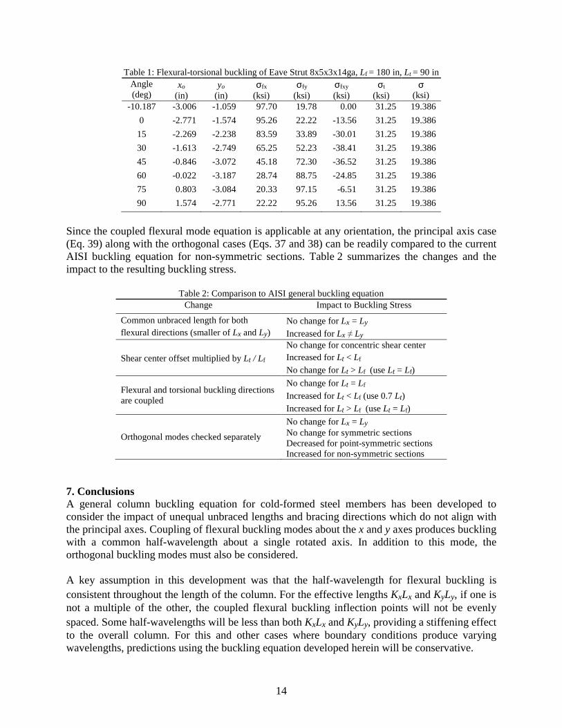
The general form of the buckling equation for the coupled flexural mode (Eq. 34) uses a common half-wavelength Lf, and accommodates the use of non-principal axes. Therefore, the resulting buckling stress is the same for any orientation of the cross-section. This is demonstrated in Table 1 where the buckling stress for the non-symmetric eave strut shown in Figure 7 is calculated using Eq. 34 for a specific set of unbraced lengths at various rotated angles.
14
Table 1: Flexural-torsional buckling of Eave Strut 8x5x3x14ga, Lf = 180 in, Lt = 90 in Angle (deg)
xo (in)
yo (in)
σfx (ksi)
σfy (ksi)
σfxy (ksi)
σt (ksi)
σ (ksi)
-10.187 -3.006 -1.059 97.70 19.78 0.00 31.25 19.386
0 -2.771 -1.574 95.26 22.22 -13.56 31.25 19.386
15 -2.269 -2.238 83.59 33.89 -30.01 31.25 19.386
30 -1.613 -2.749 65.25 52.23 -38.41 31.25 19.386
45 -0.846 -3.072 45.18 72.30 -36.52 31.25 19.386
60 -0.022 -3.187 28.74 88.75 -24.85 31.25 19.386
75 0.803 -3.084 20.33 97.15 -6.51 31.25 19.386
90 1.574 -2.771 22.22 95.26 13.56 31.25 19.386
Since the coupled flexural mode equation is applicable at any orientation, the principal axis case (Eq. 39) along with the orthogonal cases (Eqs. 37 and 38) can be readily compared to the current AISI buckling equation for non-symmetric sections. Table 2 summarizes the changes and the impact to the resulting buckling stress.
Table 2: Comparison to AISI general buckling equation Change Impact to Buckling Stress
Common unbraced length for both flexural directions (smaller of Lx and Ly)
No change for Lx = Ly Increased for Lx ≠ Ly
Shear center offset multiplied by Lt / Lf
No change for concentric shear center Increased for Lt < Lf No change for Lt > Lf (use Lt = Lf)
Flexural and torsional buckling directions are coupled
No change for Lt = Lf Increased for Lt < Lf (use 0.7 Lt) Increased for Lt > Lf (use Lt = Lf)
Orthogonal modes checked separately
No change for Lx = Ly No change for symmetric sections Decreased for point-symmetric sections Increased for non-symmetric sections
7. Conclusions A general column buckling equation for cold-formed steel members has been developed to consider the impact of unequal unbraced lengths and bracing directions which do not align with the principal axes. Coupling of flexural buckling modes about the x and y axes produces buckling with a common half-wavelength about a single rotated axis. In addition to this mode, the orthogonal buckling modes must also be considered. A key assumption in this development was that the half-wavelength for flexural buckling is consistent throughout the length of the column. For the effective lengths KxLx and KyLy, if one is not a multiple of the other, the coupled flexural buckling inflection points will not be evenly spaced. Some half-wavelengths will be less than both KxLx and KyLy, providing a stiffening effect to the overall column. For this and other cases where boundary conditions produce varying wavelengths, predictions using the buckling equation developed herein will be conservative.

15
In flexural-torsional buckling, the direction of flexure dictates the direction of rotation. Therefore, the effective length for torsional buckling may be impacted. If Lt is less than Lf, the torsional span behaves as pinned-fixed so that an effective length factor of 0.7 should be used. For cases where Lt is greater than Lf, the effective length for torsion should be equal to that for flexure. These new buckling developments provide refinements to the current AISI equations for cases with symmetry, and provide a solution for non-principal axis bracing which has not previously been available. Unequal unbraced lengths may increase the column buckling stress relative to current AISI provisions. These cases are commonly utilized in cold-formed steel framing, and proper handling is necessary to ensure safe and cost effective designs. It is therefore recommended that the AISI design provisions for column buckling be modified to incorporate these more general forms. This will benefit the engineer so that more complex rational methods such as finite element analysis are not required. 8. Acknowledgements The author would like to thank Dr. Benjamin Schafer of Johns Hopkins University for his review and valuable feedback on this study, and doctoral student Hamid Foroughi of Johns Hopkins University for performing confirmatory finite element analyses. Both of these contributions were instrumental in properly refining the developments in this investigation.

16
9. Notation A Area of cross-section Cw Torsional warping constant E Modulus of elasticity G Shear modulus of elasticity J Saint-Venant torsion constant Ix, Iy Moment of inertia about x and y axes Ixy Product of inertia about x and y axes I2 Moment of inertia about minor principal axes
Kx, Ky, Kt Effective length factors for buckling about x axis, y axis, and torsion L Column length Lx, Ly, Lt Unbraced lengths for buckling about x axis, y axis, and torsion Lf Half-wavelength for coupled flexural buckling (smaller of Lx and Ly) Mx, My Moment about x and y axes P Critical elastic buckling axial load Px, Py, Pt Critical axial load for elastic buckling about x axis, y axis, and torsion Pfx, Pfy Coupled critical axial loads for flexural buckling about the x and y axes Pfxy Coupled critical axial load component attributed to unsymmetrical bending ro Polar radius of gyration about shear center rx, ry Radius of gyration about x and y axes r2 Radius of gyration about minor principal axis
Tz Torsion per unit length of column u, v, φ Buckling displacements in the x and y directions, and angle of twist u", v", φ" Second derivative of buckling displacements with respect to z u"" , v"" , φ"" Fourth derivative of buckling displacements with respect to z x, y Orthogonal coordinate axes of cross-section corresponding to bracing directions xo, yo Coordinates of shear center relative to centroid of cross-section z Longitudinal axis of column α, β, γ, δ Dimensionless factors used in polynomial form of buckling equation σ Critical elastic buckling axial stress σex, σey, σt Critical axial stress for elastic buckling about x axis, y axis, and torsion σfx, σfy Coupled critical axial stress for flexural buckling about the x and y axes σxy Coupled critical axial stress component attributed to unsymmetrical bending References American Iron and Steel Institute (2013), Cold-Formed Steel Design Manual, 2013 Edition, Washington, DC, 2014. American Iron and Steel Institute (2016), North American Specification for the Design of Cold-Formed Steel
Structural Members, 2016 Edition, Washington, DC, 2016. Chajes, A. and Winter, G. (1965), “Torsional-Flexural Buckling of Thin-Walled Members”, Journal of the Structural
Division, ASCE Proceedings, vol. 91, Aug. 1965. Peköz, T.B. and Winter, G. (1969), “Torsional Flexural Buckling of Thin-Walled Sections under Eccentric Load,”
Journal of the Structural Division, ASCE, Vol. 95, No. ST5, May 1969. Timoshenko, S.P. and Gere, J.M. (1961), Theory of Elastic Stability, 2nd Edition, McGraw-Hill, New York, NY, 1961. Yu, W.W. (2000), Cold-Formed Steel Design, 3rd Edition, John Wiley & Sons, Inc., 2000.

17
Appendix: Buckling Stress Comparisons
Table A1. Flexural buckling stress for Z4x1.5x0.5 Lx (in)
Ly (in)
Buckling Mode
Fcre (ksi)
Fcre AISI (ksi)
Fcre FEA (ksi)
Fcre AISI / Fcre
Fcre FEA / Fcre
216 216 XY 1.440 1.440 1.439 1.000 0.999
216 108 XY 5.759 5.759 5.750 1.000 0.998
216 72 XY 12.958 12.958 12.918 1.000 0.997
216 54 XY 23.037 23.037 22.905 1.000 0.994
216 54 X 15.249 - 15.120 - 0.992
Average 1.000 0.996
Std Dev 0.000 0.003
Table A2. Flexural-torsional buckling stress for C4x1.5x0.5 Lx (in)
Lt (in)
Lt/Lx (in)
Fcre (ksi)
Fcre AISI (ksi)
Fcre FEA (ksi)
Fcre AISI / Fcre
Fcre FEA / Fcre
54 54 1 32.631 32.631 32.273 1.000 0.989
78 78 1 20.138 20.138 19.867 1.000 0.987
108 108 1 14.430 14.430 14.195 1.000 0.984
144 144 1 11.378 11.378 11.184 1.000 0.983
180 180 1 9.575 9.575 9.423 1.000 0.984
216 216 1 8.204 8.204 8.092 1.000 0.986
72 144 2 22.153 12.742 21.918 0.575 0.989
90 180 2 17.213 11.380 16.998 0.661 0.988
126 252 2 12.647 9.942 12.461 0.786 0.985
144 72 0.5 29.676 17.607 29.362 0.593 0.989
180 90 0.5 19.746 12.809 19.650 0.649 0.995
216 108 0.5 14.074 9.913 14.037 0.704 0.997
252 126 0.5 10.515 7.938 10.497 0.755 0.998
144 36 0.25 33.598 27.519 33.077 0.819 0.985
180 45 0.25 21.507 17.943 21.357 0.834 0.993
216 54 0.25 14.939 12.697 14.891 0.850 0.997
252 63 0.25 10.978 9.497 10.964 0.865 0.999
288 72 0.25 8.407 7.392 8.402 0.879 0.999
Average 0.832 0.990
Std Dev 0.146 0.006

18
Table A3. Buckling stress for Eave Strut 4x3x2 Lx (in)
Ly (in)
Lt (in)
Buckling Mode
Fcre (ksi)
Fcre FEA (ksi)
Fcre FEA / Fcre
XYT 4.734 4.700 0.993
216 216 216 XT 5.026 4.986 0.992
T 5.025 4.986 0.992
XYT 7.269 7.194 0.990
216 216 108 XT 18.346 18.042 0.983
T 12.125 12.095 0.998
XYT 11.900 11.828 0.994
216 108 108 XT 18.346 18.042 0.983
T 12.125 12.095 0.998
XYT 23.428 23.173 0.989
216 72 72 XT 21.936 21.867 0.997
T 23.758 23.427 0.986
XYT 29.063 28.727 0.988
216 108 54 XT 22.312 22.059 0.989
T 40.013 38.498 0.962
XYT 39.518 38.488 0.974
216 54 108 XT 18.346 18.042 0.983
T 12.125 12.095 0.998
Average 0.988
Std Dev 0.009