stability analysis of a hybrid power plant: an analysis
TRANSCRIPT

Abstract—Transient analysis plays an important role in
power system. Transient analysis is aimed at determining
whether a system will remain in synchronism with other
generating plants after disturbances. In this paper, transient
stability for a small power plant (80MW) coupled with a small
solar plant has been studied through ETAP software. The plant
is operating as IPP
(Independent Power Producer) and owned by United Power
Generation & Distribution Co. ltd. (UPGD) under United
Group, Bangladesh. Effect of fault on generating plant and
solar plant side has been studied. In this paper our main aim is
to show the effect of any type of fault on the power plant side is
very low when fault occurs at solar plant side. The plant almost
remains unhindered due to fault in the solar part of the
proposed hybrid plant. Complete analysis has been done under
ETAP software environment to predict the stability of the
hybrid plant. As Bangladesh government is taking up a project
to install MW range solar PV based plant that will be hooked up
with the national grid, the present study will give an idea as to
predict the behavior of the hybrid system especially as far as the
stability of the overall system is concerned.
Index Terms—ETAP, transient stability analysis, solar
system, disturbance, system stability, inertia constant.
I. INTRODUCTION
Synchronous generators respond to fast changes in
electromechanical swings and during these swings generators
get into a situation when the rotor angle stabilizes at a new
value or the rotor angle will gradually increase which may
take the system to a loss of synchronism [1]. The vital aim of
transient stability is to determine whether the system returns
to a steady state value after the clearance of disturbance [2].
Normally without solar plant the effect of fault at any point of
the plant is high. The proposed method is developed based on
the swing equation and the theory of control system. The
well-known classical swing equation which is related to
synchronous generator rotor swing angle is [3],
where,
Manuscript received December 30, 2018; revised March 1, 2019. This
work was supported by the research and development project „Efficient design for biodynamic lighting to promote the circadian rhythm in offices
buildings‟ (ref BIA2017-86997-R), as well as the TEP-130 Research group.
Shazzadul Islam is with the Department of Electrical and Electronic Engineering, Global University Bangladesh (GUB), Barisal, Bangladesh
(e-mail: [email protected]).
Mohammad Fayyaz Khan is a Pro Vice Chancellor, Green University of
Bangladesh
Pa is the accelerating power,
Pm is the mechanical power,
Pe is the electrical power output,
𝑠 is the synchronous angular velocity of the rotor,δ is the
synchronous machine rotor angle,
H is the inertia constant.
The power output of the single machine connected to
anInfinite bus at any instant of time is,
𝑠
The mechanical power input equal to the pre fault
electrical power output at an initial angle δ0 is given as,
𝑠
System reactance is different during occurrence of fault
from the reactance after the clearing the fault.
A number of PV panels connected in series and in parallel
giving a DC output for the incident of irradiance. Hybrid
systems can address limitations in terms of fuel flexibility,
the major types of hybrid power system are, Grid Connected
Hybrid Systems, Isolated Grid Hybrid Systems.
II. LAYOUT OF THE POWER PLANT
For the stability analysis, as already mentioned a small
plant of 80 MW has been considered with twelve generators
running in parallel. The plant is named as DEPZ plant located
at EPZ area SAVAR, Dhaka. The plant has 12 generators
(combination of Wartsilla & Rolls Royce generators)
connected to two separate buses known as WARTSILA(DW)
and Rolls Royce(RR) bus respectively. Four generators are
connected to WARTSILA bus each is rated as 8.73MW and
five generators connected to Rolls Royce bus each rated as
9.34MW. There are three small Generators known as MTU
connected to WARTSILA bus.
TABLE I: SPECIFICATIONS FOR WARTSILA GENERATORS
Output 8.73 MW
voltage 11/11000V
current 573A
speed 750 rpm
Over speed 900 rpm
Weight 27000 kg
Inertia 2150
p.f .80
Number of gen 4
Stability Analysis of a Hybrid Power Plant: An Analysis
through ETAP Software
Md. Shazzadul Islam and Muhammad Fayyaz Khan
International Journal of Engineering and Technology, Vol. 11, No. 2, April 2019
139DOI: 10.7763/IJET.2019.V11.1136

TABLE II: SPECIFICATIONS FOR ROLLS ROYCE
Output 9.34 MW
Current 638 A
Weight 34500 kg
Speed 750 rpm
Number of gen 5
Fig. 1. Sin line diagram and load flow analysis of the system.
TABLE III: SPECIFICATION OF SOLAR PLANT
Watt/Panel 214.5
Series Panel/Array 4
Parallel Panel/Array 4
Total Panel/Array 16
Fill Factor 78.11%
efficiency 14%
Total KW 20
III. TRANSIENT ANALYSIS OF THE SYSTEM
Transient stability the ability of a power system to
maintain synchronism under large disturbance conditions like
severe three phase faults, line switching etc. We can thus
define the power system stability as the ability of the power
system to return to steady state without losing synchronism.
The general main problem of a power plant is to maintain
stability at the time of large disturbances. When situation is
critical, that time generators of this power plant are
disconnected from the system one by one, they can no longer
run with the system. This situation arises as inertia of all the
generators are very low. Our main objective is to create
symmetrical fault in different sensitive points of the plant and
visualize the impact of fault on stability. Stability analysis
has been done under different conditions like when the plant
is operating under grid mode or islanding mode.
Grid mode operation:
a. Fault on 11kv Rolls-Royce bus
b. Fault on solar plant
Island mode operation
c. Fault on 11kv bus and solar plant side.
In island mode operation effect of fault is same if fault
occur anywhere of the plant. That‟s why we consider only
11kv bus. During simulation there are two interconnector
namely ic1 and ic2 kept open and close simultaneously.
IV. DESIGN OF PROPOSED SOLAR PV PLANT
UPGDCL‟s Power Plant inside Dhaka Export Processing
Zone is situated over an area of 6,125.13 sq. meters. Inside
the power plant has some free space, so company take a
decision to make a hybrid power plant. The main concern of
this paper is analysis stability of the DEPZ power plant if we
add a solar plant in the existing power plant. The longitude
and latitude of the land are 23.70 N & 90.40 E Respectively.
As the land is predominately made up of hard soil. Also
during monsoon season the land is not inundated by water, so
there is no problem in rainy season. The amount of power that
can be generated from PV panels installed on the land for an
approximate area of 0.5 acres.
Fig. 2. Proposed land near the DEPZ power plant.
Fig. 3. Speed of wartsila rolls-royce and Mtu.
International Journal of Engineering and Technology, Vol. 11, No. 2, April 2019
140

V. RESULTS AND DISCUSSION
Case1:
At first fault crated on 11KV RR bus and two
interconnector kept close then analyze the stability of the
system. Fault occurs at .5s and cleared at .6s clearing time of
fault is .1s.this is shown in Fig. 3 to Fig. 7.
Fig. 4. Bus voltage of RR and Wartsila.
Fig. 5. Bus voltage solar plant.
Fig. 6. Terminal current of RR, DW, MTU
Fig. 7. Terminal current of solar panel.
From Fig. 3 it can be seen that all generators disconnected
from the system due to high amount of short circuit current.
TABLE IV: DATA AT FAULT ON RR BUS (IC1&IC2 CLOSED)
Bus
Name
Pre fault During fault Post fault
(A) (KV) (A) (KV) (A) (KV)
RR 343 11 4800 0 343 11
DW 246 11 3600 0 246 11
Solar
bus 48 .22 49 .18 48 .22
In gas power plant side effect is much higher than solar
plant, because ic1 and ic2 is closed and solar plant is
connected to the grid. In case2 analyzed the effect of fault
when ic1 and ic2 is opened.
Case2:
Again fault is created on 11KV RR bus (ic1&ic2 open)
then analyzed stability of the both plants.
Fig. 8. Speed of DW, DR and MTU.
Fig. 9. Bus voltage of DR and DW.
Fig.10. Bus voltage solar plant.
Fig. 11. Terminal current of RR, DW.
Fig. 12. Terminal current of solar panel.
TABLE V: DATA AT FAULT ON RR BUS (IC1&IC2 OPEN)
Bus
Name
Pre fault During fault Post fault
(A) (KV) (A) (KV) (A) (KV)
RR 490 11 5380 0 490 11
DW 275 11 460 0 275 11
Solar bus
48 .22 48.5 .20 48 .22
From figure8 only faulty bus generators disconnected from
the system. So it can be seen that when ic1 & ic2 is open then
effect of fault reduces the whole system except faulty bus. In
solar plant bus fault current further decreases.
Case3:
Fault created on solar plant bus, fault occurs at 0.5s and
cleared at 0.6s clearing time of fault is 0.1s.results shown in
below.
International Journal of Engineering and Technology, Vol. 11, No. 2, April 2019
141
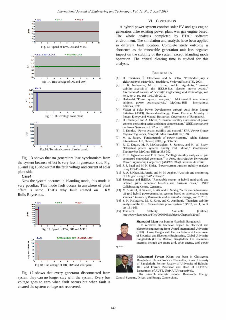
Fig. 13. Speed of DW, DR and MTU.
Fig. 14. Bus voltage of DR and DW.
Fig. 15. Bus voltage solar plant.
Fig.16. Terminal current of solar panel.
Fig. 13 shows that no generators lose synchronism from
the system because effect is very less in generator side. Fig.
15 and Fig.16 shows that the fault voltage and current of solar
plant side.
Case4:
Now the system operates in Islanding mode, this mode is
very peculiar. This mode fault occurs in anywhere of plant
effect is same. That‟s why fault created on 11KV
Rolls-Royce bus.
Fig. 17. Speed of DW, DR and MTU
Fig.18. Bus voltage of DR, DW and solar plant.
Fig. 17 shows that every generator disconnected from
system they can no longer stay with the system. Every bus
voltage goes to zero when fault occurs but when fault is
cleared the system voltage not recovered.
VI. CONCLUSION
A hybrid power system consists solar PV and gas engine
generators .The existing power plant was gas engine based.
The whole analysis completed by ETAP software
environment. The simulation and analysis have been applied
in different fault location. Complete study outcome is
shortened as the renewable generation unit less negative
impact on the stability of the system except islanding mode
operation. The critical clearing time is studied for this
analysis.
REFERENCES
[1] D. Reváková, Ž. Eleschová, and A. Beláň, “Prechodné javy v
elektrizačných sústavách,” Bratislava, Vydavateľstvo STU, 2008.
[2] S. K. Nallagalva, M. K. Kirar, and G. Agnihotri, “Transient stability analysis of the IEEE 9-Bus electric power system,”
International Journal of Scientific Engineering and Technology, vol.
no.1, no. 3, pp. 161-166, July 2012.
[3] Hadisadat, “Power system analysis,” McGraw-hill international
editions, power systemanalysis,” McGraw-Hill International
Editions, 1999. [4] Vision of Solar Power Development through Asia Solar Energy
Initiative (ASEI), Renewable-Energy, Power Division, Ministry of
Power, Energy and Mineral Resources, Government of Bangladesh. [5] D. Chatterjee and A. Ghosh, “Transient stability assessment of power
systems containing series and shunt compensators,” IEEE transactions
on Power Systems, vol. 22, no. 3, 2007. [6] P. Kundur, “Power system stability and control,” EPRI Power System
Engineering Series, Newyork, Mc-Graw-Hill Inc,1994.
[7] M. A. Salam, “Fundamentals of power systems,” Alpha Science International Ltd, Oxford, 2009, pp. 336-358.
[8] R. C. Dugan, M. F. McGranaghan, S. Santoso, and H. W. Beaty, “Electrical power systems quality 2nd Edition,” Professional
Engineering, McGraw-Hill pp 383-392.
[9] R. K. Jaganathan and T. K. Saha, “Voltage stability analysis of grid connected embedded generators,” in Proc. Australasian Universities
Power Engineering Conference (AUPEC 2004) Brisbane Australia.
[10] J. S. Patel and M. N. Sinha, “Power system transient stability analysis using ETAP software”.
[11] R. A. J. Khan, M. Junaid, and M. M. Asgher, “Analysis and monitoring
of 132 grid using ETAP software”. [12] Siemense and IRENA, “Renewable energy in hybrid mini-grids and
isolated grids: economic benefits and business cases,” UNEP
Collaborating Centre, Germany. [13] M. S. Aziz1, U. Saleem, E. Ali, and K. Siddiq, “A review on bi-source,
off-grid hybrid powergeneration systems based on alternative energy
sources,” Journal of Renewable and Sustainable Energy, vol. 7, 2015. [14] S. K. Nallagalva, M. K. Kirar, and G. Agnihotri, “Transient stability
analysis of the IEEE 9-bus electric power system,” IJSET, vol. 1, no. 3,
pp. 161-166. [15] Transient Stability. Available: [Online]:
http://www.kau.edu.sa/Files/0056868/Subjects/Chapter%20pdf
Shazzadul Islam was born in Noakhali, Bangladesh.
He received his bachelor degree in electrical and
electronic engineering from United International University
(UIU), Dhaka, Bangladesh. He is a lecturer at Department
of Electrical and Electronic Engineering, Global University
Bangladesh (GUB), Barisal, Bangladesh. His researches interests include are smart grid, solar energy, and power
system.
Mohammad Fayyaz Khan was born in Chittagong,
Bangladesh. He is a Pro Vice Chancellor, Green University of Bangladesh. Former Faculty of University of Bahrain,
IUT and Former Professor and Head of EEE/CSE
Department of AUST, UAP, UIU respectively. His research interests include: Renewable Energy,
Control Systems, Drives, and Energy Conversions.
International Journal of Engineering and Technology, Vol. 11, No. 2, April 2019
142