stability analysis of 3-d conventional pallet rack structures with semi-rigid...
TRANSCRIPT
International Journal of Advanced Structural Engineering, Vol. 1, No. 2, Pages 153-181, December 2009
© Islamic Azad University, South Tehran Branch
153
STABILITY ANALYSIS OF 3-D CONVENTIONAL PALLET RACK STRUCTURES WITH SEMI-RIGID CONNECTIONS
Kamal M. Bajoria1, Keshav K. Sangle2 and Rajshekar S. Talicotti3
Department of Civil Engineering, Indian Institute of Technology Bombay, Mumbai, India
Received 1 December 2009 Revised 20 December 2009
Accepted 23 December 2009
This paper describe the three dimensional finite element modeling and buckling analysis of conventional pallet racking system with semi rigid connection. In this study three dimensional models of conventional pallet racking system were prepared using the finite element program ANSYS and finite element analysis carried out on conventional pallet racks with the 18 types of column sections developed along with semi-rigid connections. A parametric study was carried out to compare the effective length approach and the finite element method for accuracy and appropriateness for cold-formed steel frame design. Numerous frame elastic buckling analyses were carried out to evaluate the alignment chart and the AISI torsional-flexural buckling provisions. The parameters that influence the value of Kx for column flexural buckling were examined in this study. The alignment chart and the AISI torsional-flexural buckling provisions, used to obtain the effective lengths and elastic buckling load of members were also evaluated. Results showed that the elastic buckling load obtained from the AISI torsional-flexural buckling provisions is generally conservative compared to the results obtained from performing frame elastic buckling analysis. Results also showed that, the effective length approach is more conservative than the finite element approach.
Keywords: finite element Analysis, cold formed steel, semi- rigid connections
1. Introduction
The behavior of industrial storage racks depends on how the individual components like beam to column connections, column bases and members perform interactively with each other. The 1 Associate Professor 2 Research Scholar 3 Ex-Research Scholar Correspondence to: Dr. Kamal M. Bajoria, Dept. of Civil Engineering, Indian Institute of Technology Bombay, Powai, Mumbai 400076, India, E-mail: [email protected]
Published online December 2009 at (http://journals.azad.ac.ir/IJASE)

K. M. Bajoria et al.
/ IJASE: Vol. 1, No. 2, December 2009 154
behavior of three dimensional frames is very complex because of many parameters such as semi-rigid nature of connections, presence of significant perforations in uprights, and susceptibility to local buckling and torsional-flexural buckling. As to which method of analysis is best to solve this problem will certainly depend on the tools available to the designer. The analysis model can be as simple as using a sub-structure model such as isolating the column and using the alignment chart, or as sophisticated as using numerical methods to analyze the entire frame. With the availability of powerful computers and software, the latter approach has become more attractive, allowing more complex and efficient designs.
The analysis and design of thin walled cold-formed steel pallet racking structure with perforated open upright section and semi-rigid joints presents several challenges to the structural engineers. Presently, for the design of these structures few code of practice like draft Australian code AS4084 (1993), AISI (2001), SEMA (1985) and the specifications published by the Rack Manufacturer’s Institute (RMI -2005) serves as guidelines for analysis and design of rack structures.
Bajoria and Talikoti (2006) determined the flexibility of beam –to-column connections used in conventional pallet rack racking system by experimentally by conducting double cantilever test on the developed connectors. They also performed full scale frame test to verify the results of double cantilever method. The experimental and finite element results are compared in the paper. Beale and Godley (2004) performed sway analysis of spliced rack structures. The structures are analyzed by considering an equivalent free sway column and using computer algebra generated modified stability functions to incorporate the non-linear P- δ effects. The effect of semi-rigid beam to upright, splice to upright connections are fully included in the analysis. Each section of upright between successive beam levels in the pallet rack is considered to be a single column element. The results of the analysis are compared with a traditional finite element solution of the problem. Godley et al. (2000) performed analysis and design of un -braced pallet rack structures subjected to horizontal and vertical loads. The structures are analyzed by considering an equivalent free-sway column and solving the differential equations of flexure, including P-δ effect. Initial imperfections within the frame are allowed. Results of the analysis are compared with a traditional non-linear finite element solution of the same problem. Davis (1992) and Lewis (1997) worked on the down-aisle stability of rack structures. In his analysis, a single internal upright column carrying both vertical and horizontal loads was used. The model allowed for semi-rigid connections between beams and uprights and between the bases of uprights and the floors. However, the model only allowed for column flexibility below the level of the second beam, the rest of the column being treated as rigid. This assumption becomes increasingly unsafe as the number of storey levels increases. Haris and Hancock (2002) investigated the buckling behavior of high-rise storage rack structures. Textbooks by Rhodes (1991), Salmon and Johnson (1996) and Timoshenko and Gere (1961) provided in depth explanations of the fundamental basis
Stability Analysis of 3-D Conventional Pallet Rack Structures with Semi-Rigid Connections
IJASE: Vol. 1, No. 2, December 2009 / 155
for the design of cold-formed steel and metal structures.. The major work on cold-formed channel section columns has been performed by Young and Rasmussen (2007, 1999, 2008a, 2008b). They have focused on the behavior of cold-formed plain and lipped channel columns. The different effects of local buckling on the behavior of fixed-ended and pin-ended channels were investigated by Young and Rasmussen (1994) including the shift of the effective centroid and theoretical bifurcation models. The effects of local buckling on channel column strength are accurately quantified in these papers for both lipped and un-lipped channels. Teh et.al (2004) presented new studies regarding the three dimensional frame buckling behavior of high rise adjustable pallet racks and accuracy of 2-D analysis based procedures in determining the elastic flexural –torsional bucking stress of an upright section. Abdel–Jaber et.al (2006) performed theoretical and experimental investigation of pallet rack structures under sway. In this paper they have described the use of mirror arrangement of portal frames lying horizontally and tied together by means of a tension jack to investigate the free sway behavior of pallet rack structures. Abdel-Jaber et.al (2005) also analyzed portal frames under combinations of side and axial loading. Three different models were used to approximate the moment-rotation curve of the semi rigid beam-end connector.
This paper deals with the finite element stability analysis of three dimensional frames of a cold-form steel storage rack structures with semi rigid connections. Results are presented from the complete 3-D FEM analysis carried out on three dimensional frames with 18 types of column sections developed along with comparison of AISI provisions. 2. Column Sections Used in the Study
The column (upright) sections in storage racks are perforated for the purpose of easy assembly of the beam end connector. It is well known that the presence of such perforation reduces the local buckling strength of the individual element and the overall buckling strength of the section. The significance of this reduction will however depend on the geometry and material properties of the member and the boundary conditions. The current specifications allow the use of un-perforated section properties to predict the overall elastic buckling strength of perforated members, by assuming that the presence of such perforation does not have significant influence on the reduction of the overall elastic buckling strength.
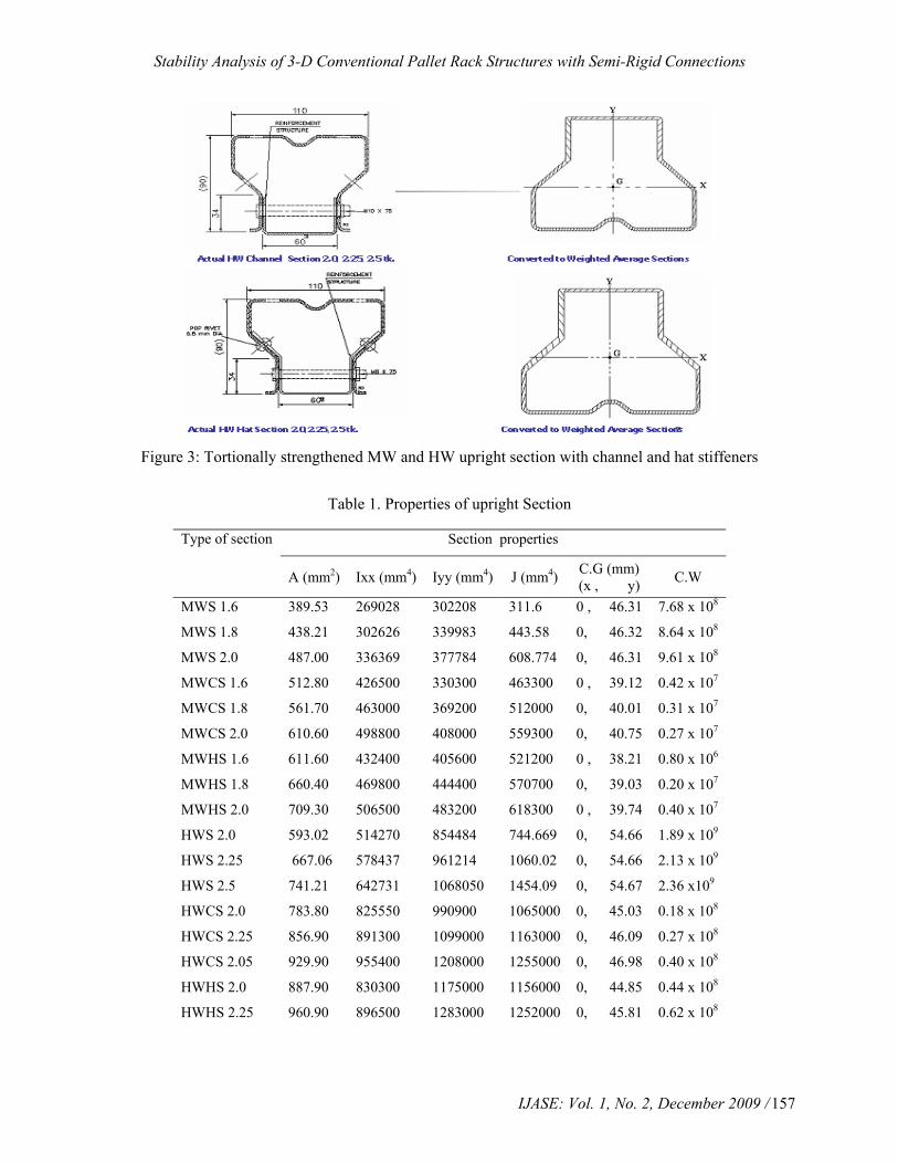
In this paper open sections and torsionally strengthened sections were used. Original open sections were strengthened by providing channel and hat stiffeners to avoid the local buckling of uprights. These sections are MW (Medium Weight) column section having three thicknesses 1.6 mm, 1.8 mm and 2.0 mm each with hat and channel stiffener and HW (Heavy Weight) column section having three thicknesses 2.0 mm, 2.25 mm and 2.5 mm each with hat and channel stiffener. Their cross sectional geometry is given in Figures 1, 2 and 3. Purpose of choosing three

K. M. Bajoria et al.
/ IJASE: Vol. 1, No. 2, December 2009 156
different thicknesses is to know the change in behavior when the sections are made locally stable by having higher thickness. 3. Calculations of Sectional Properties
For the above sections, sectional properties are calculated based on weighted average section. A weighted average section is a section that uses an average thickness in the web portion to account for the absence of the material due to the holes along the length of the section and additional thickness for the additional material of channel and hat stiffener. Excel program is developed to calculate the sectional properties of sections used in this study. Sectional properties of upright sections are given in Table 1.
Figure 1. Medium weight upright section 1.6, 1.8 and 2.0 mm
Figure 2. Heavy weight upright section 2.0, 2.25 and 2.5 mm
Stability Analysis of 3-D Conventional Pallet Rack Structures with Semi-Rigid Connections
IJASE: Vol. 1, No. 2, December 2009 / 157
Figure 3: Tortionally strengthened MW and HW upright section with channel and hat stiffeners
Table 1. Properties of upright Section
Type of section Section properties
A (mm2) Ixx (mm4) Iyy (mm4) J (mm4) C.G (mm) (x , y) C.W
MWS 1.6 389.53 269028 302208 311.6 0 , 46.31 7.68 x 10⁸
MWS 1.8 438.21 302626 339983 443.58 0, 46.32 8.64 x 10⁸
MWS 2.0 487.00 336369 377784 608.774 0, 46.31 9.61 x 10⁸
MWCS 1.6 512.80 426500 330300 463300 0 , 39.12 0.42 x 10⁷
MWCS 1.8 561.70 463000 369200 512000 0, 40.01 0.31 x 10⁷
MWCS 2.0 610.60 498800 408000 559300 0, 40.75 0.27 x 10⁷
MWHS 1.6 611.60 432400 405600 521200 0 , 38.21 0.80 x 10⁶
MWHS 1.8 660.40 469800 444400 570700 0, 39.03 0.20 x 10⁷
MWHS 2.0 709.30 506500 483200 618300 0 , 39.74 0.40 x 10⁷
HWS 2.0 593.02 514270 854484 744.669 0, 54.66 1.89 x 10⁹
HWS 2.25 667.06 578437 961214 1060.02 0, 54.66 2.13 x 10⁹
HWS 2.5 741.21 642731 1068050 1454.09 0, 54.67 2.36 x10⁹
HWCS 2.0 783.80 825550 990900 1065000 0, 45.03 0.18 x 10⁸
HWCS 2.25 856.90 891300 1099000 1163000 0, 46.09 0.27 x 10⁸
HWCS 2.05 929.90 955400 1208000 1255000 0, 46.98 0.40 x 10⁸
HWHS 2.0 887.90 830300 1175000 1156000 0, 44.85 0.44 x 10⁸
HWHS 2.25 960.90 896500 1283000 1252000 0, 45.81 0.62 x 10⁸
K. M. Bajoria et al.
/ IJASE: Vol. 1, No. 2, December 2009 158
4. Factors Affecting the Stability of Rack Structures
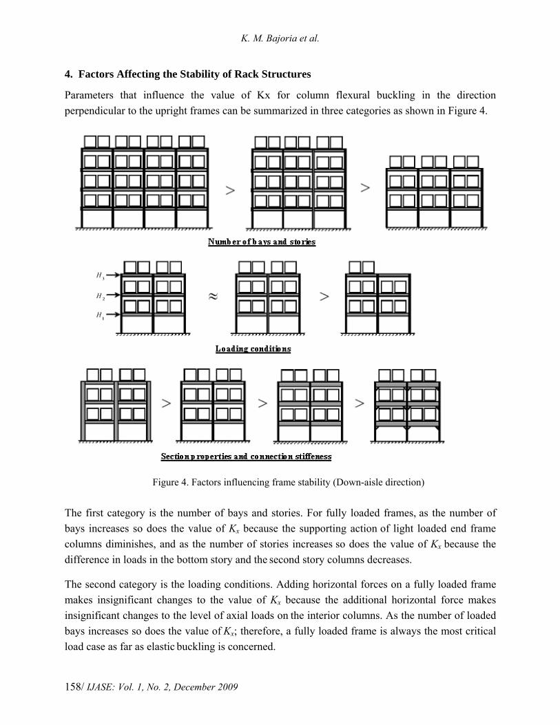
Parameters that influence the value of Kx for column flexural buckling in the direction perpendicular to the upright frames can be summarized in three categories as shown in Figure 4.
Figure 4. Factors influencing frame stability (Down-aisle direction)
The first category is the number of bays and stories. For fully loaded frames, as the number of bays increases so does the value of Kx because the supporting action of light loaded end frame columns diminishes, and as the number of stories increases so does the value of Kx because the difference in loads in the bottom story and the second story columns decreases.
The second category is the loading conditions. Adding horizontal forces on a fully loaded frame makes insignificant changes to the value of Kx because the additional horizontal force makes insignificant changes to the level of axial loads on the interior columns. As the number of loaded bays increases so does the value of Kx; therefore, a fully loaded frame is always the most critical load case as far as elastic buckling is concerned.
Stability Analysis of 3-D Conventional Pallet Rack Structures with Semi-Rigid Connections
IJASE: Vol. 1, No. 2, December 2009 / 159
The third category is the section properties and connection stiffness. As the column size increases so does the value of Kx; however as the beam size and the connection stiffness increases the value of Kx will decrease because additional restraint from the beam and connection stiffness helps prevent the frame from side sway buckling.
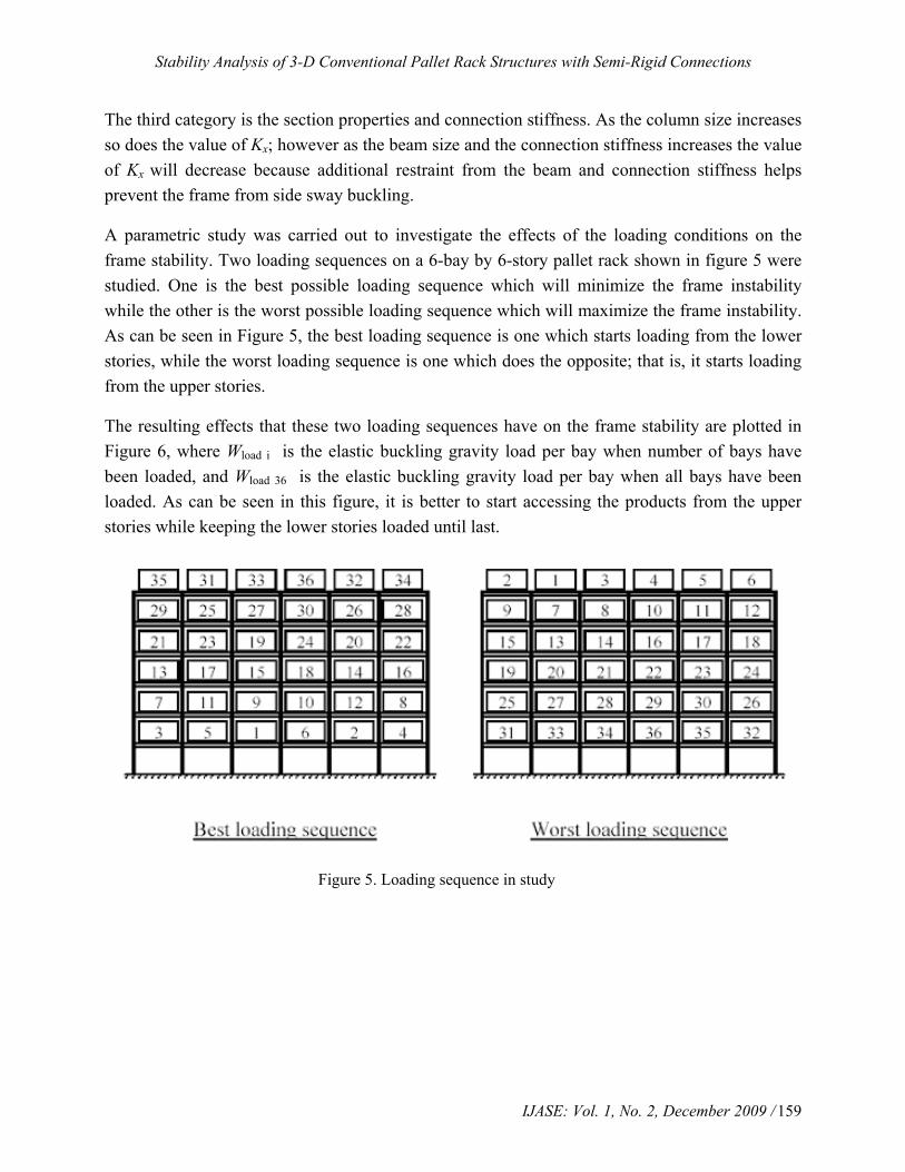
A parametric study was carried out to investigate the effects of the loading conditions on the frame stability. Two loading sequences on a 6-bay by 6-story pallet rack shown in figure 5 were studied. One is the best possible loading sequence which will minimize the frame instability while the other is the worst possible loading sequence which will maximize the frame instability. As can be seen in Figure 5, the best loading sequence is one which starts loading from the lower stories, while the worst loading sequence is one which does the opposite; that is, it starts loading from the upper stories.
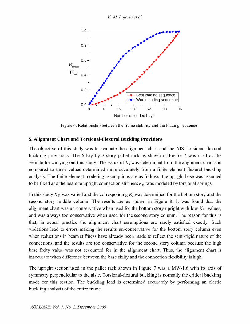
The resulting effects that these two loading sequences have on the frame stability are plotted in Figure 6, where Wload i is the elastic buckling gravity load per bay when number of bays have been loaded, and Wload 36 is the elastic buckling gravity load per bay when all bays have been loaded. As can be seen in this figure, it is better to start accessing the products from the upper stories while keeping the lower stories loaded until last.
Figure 5. Loading sequence in study
K. M. Bajoria et al.
/ IJASE: Vol. 1, No. 2, December 2009 160
0 6 12 18 24 30 360.0
0.2
0.4
0.6
0.8
1.0
iLoad
36Load
WW
Number of loaded bays
Best loading sequence Worst loading sequence
Figure 6. Relationship between the frame stability and the loading sequence
5. Alignment Chart and Torsional-Flexural Buckling Provisions
The objective of this study was to evaluate the alignment chart and the AISI torsional-flexural buckling provisions. The 6-bay by 3-story pallet rack as shown in Figure 7 was used as the vehicle for carrying out this study. The value of Kx was determined from the alignment chart and compared to those values determined more accurately from a finite element flexural buckling analysis. The finite element modeling assumptions are as follows: the upright base was assumed to be fixed and the beam to upright connection stiffness Kθ was modeled by torsional springs.
In this study Kθ was varied and the corresponding Kx was determined for the bottom story and the second story middle column. The results are as shown in Figure 8. It was found that the alignment chart was un-conservative when used for the bottom story upright with low Kθ values, and was always too conservative when used for the second story column. The reason for this is that, in actual practice the alignment chart assumptions are rarely satisfied exactly. Such violations lead to errors making the results un-conservative for the bottom story column even when reductions in beam stiffness have already been made to reflect the semi-rigid nature of the connections, and the results are too conservative for the second story column because the high base fixity value was not accounted for in the alignment chart. Thus, the alignment chart is
inaccurate when difference between the base fixity and the connection flexibility is high.
The upright section used in the pallet rack shown in Figure 7 was a MW-1.6 with its axis of symmetry perpendicular to the aisle. Torsional-flexural buckling is normally the critical buckling mode for this section. The buckling load is determined accurately by performing an elastic buckling analysis of the entire frame.

Stability Analysis of 3-D Conventional Pallet Rack Structures with Semi-Rigid Connections
IJASE: Vol. 1, No. 2, December 2009 / 161
Figure 7. Storage rack in study
0 20 40 60 80 100 1201
2
3
4
5
6
Kx
Kθ , kN-m./rad
Alignment chart (Bottom story) Alignment chart (Second story) Buckling Analysis (Second story) Buckling Analysis (Bottom story)
Figure 8: Evaluation of the alignment chart
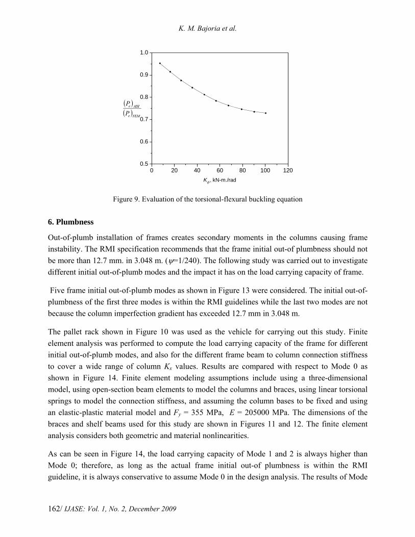
The results of using these two approaches to determine the buckling load of the bottom story middle column are compared in Figure 9. The AISI buckling equation is computed based on the values of Kx determined from flexural buckling analysis, which were given in Figure 8, and Kt = 0.717 determined from a torsional buckling analysis. It was found that the AISI torsional-flexural buckling provisions become gradually more conservative as the value of Kθ increases.
K. M. Bajoria et al.
/ IJASE: Vol. 1, No. 2, December 2009 162
0 20 40 60 80 100 1200.5
0.6
0.7
0.8
0.9
1.0
( )( )FEMe
AISIe
PP
Kθ , kN-m./rad
Figure 9. Evaluation of the torsional-flexural buckling equation 6. Plumbness
Out-of-plumb installation of frames creates secondary moments in the columns causing frame instability. The RMI specification recommends that the frame initial out-of plumbness should not be more than 12.7 mm. in 3.048 m. (ψ=1/240). The following study was carried out to investigate different initial out-of-plumb modes and the impact it has on the load carrying capacity of frame.
Five frame initial out-of-plumb modes as shown in Figure 13 were considered. The initial out-of-plumbness of the first three modes is within the RMI guidelines while the last two modes are not because the column imperfection gradient has exceeded 12.7 mm in 3.048 m.
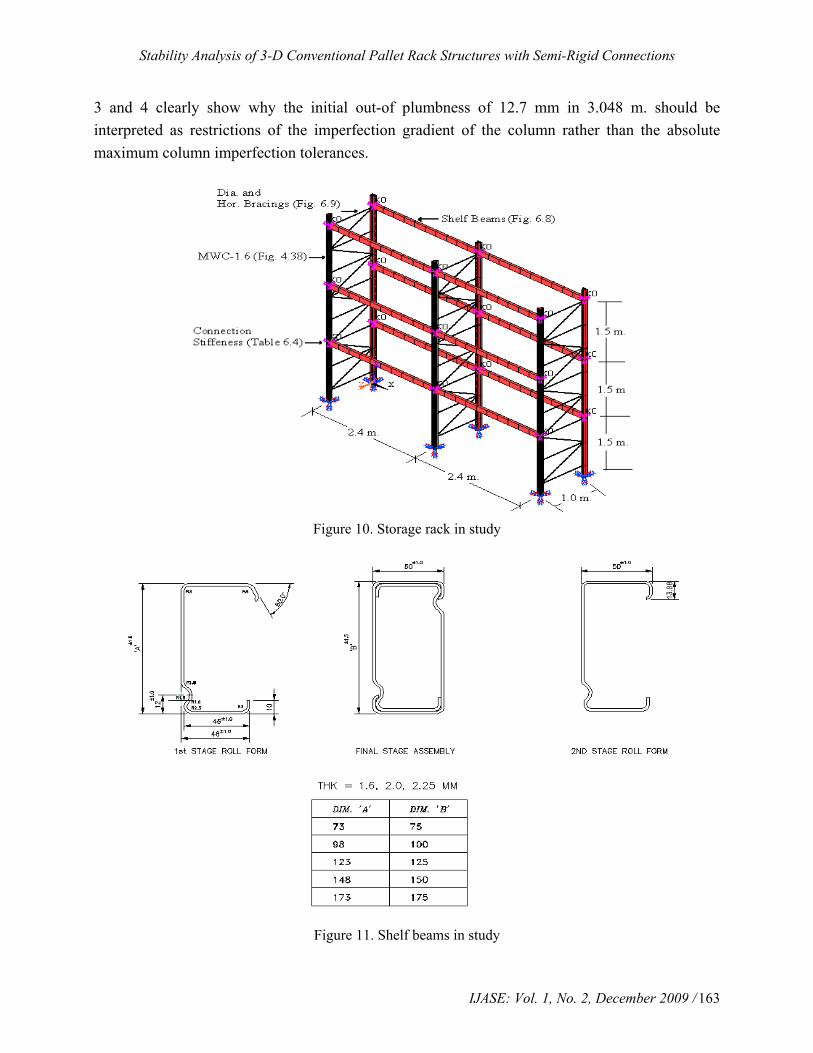
The pallet rack shown in Figure 10 was used as the vehicle for carrying out this study. Finite element analysis was performed to compute the load carrying capacity of the frame for different initial out-of-plumb modes, and also for the different frame beam to column connection stiffness to cover a wide range of column Kx values. Results are compared with respect to Mode 0 as shown in Figure 14. Finite element modeling assumptions include using a three-dimensional model, using open-section beam elements to model the columns and braces, using linear torsional springs to model the connection stiffness, and assuming the column bases to be fixed and using an elastic-plastic material model and Fy = 355 MPa, E = 205000 MPa. The dimensions of the braces and shelf beams used for this study are shown in Figures 11 and 12. The finite element analysis considers both geometric and material nonlinearities.
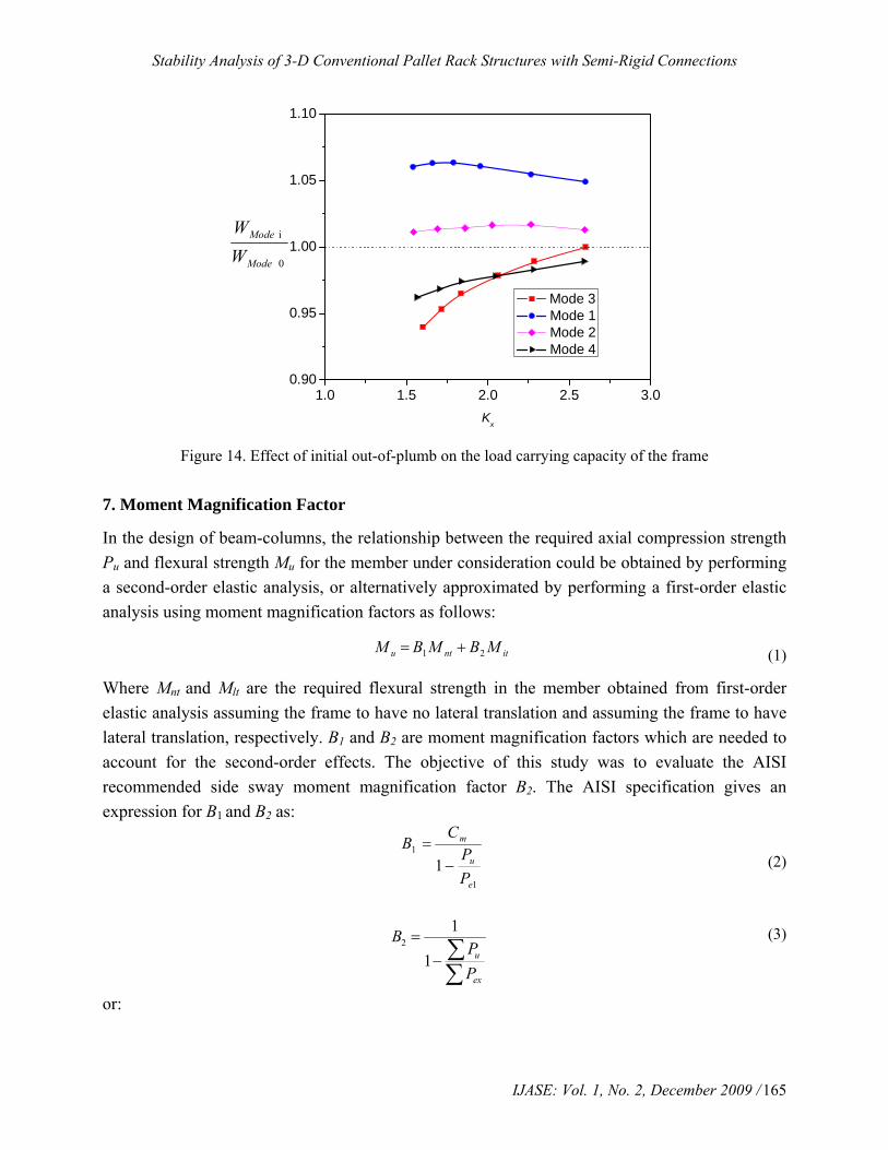
As can be seen in Figure 14, the load carrying capacity of Mode 1 and 2 is always higher than Mode 0; therefore, as long as the actual frame initial out-of plumbness is within the RMI guideline, it is always conservative to assume Mode 0 in the design analysis. The results of Mode
Stability Analysis of 3-D Conventional Pallet Rack Structures with Semi-Rigid Connections
IJASE: Vol. 1, No. 2, December 2009 / 163
3 and 4 clearly show why the initial out-of plumbness of 12.7 mm in 3.048 m. should be interpreted as restrictions of the imperfection gradient of the column rather than the absolute maximum column imperfection tolerances.
Figure 10. Storage rack in study
Figure 11. Shelf beams in study

K. M. Bajoria et al.
/ IJASE: Vol. 1, No. 2, December 2009 164
Figure 12. Horizontal and diagonal braces in study
Figure 13. Different modes of frame initial out-of-plumb
Stability Analysis of 3-D Conventional Pallet Rack Structures with Semi-Rigid Connections
IJASE: Vol. 1, No. 2, December 2009 / 165
1.0 1.5 2.0 2.5 3.00.90
0.95
1.00
1.05
1.10
0
i
Mode
Mode
WW
Kx
Mode 3 Mode 1 Mode 2 Mode 4
Figure 14. Effect of initial out-of-plumb on the load carrying capacity of the frame 7. Moment Magnification Factor
In the design of beam-columns, the relationship between the required axial compression strength Pu and flexural strength Mu for the member under consideration could be obtained by performing a second-order elastic analysis, or alternatively approximated by performing a first-order elastic analysis using moment magnification factors as follows:
itntu MBMBM 21 += (1)
Where Mnt and Mlt are the required flexural strength in the member obtained from first-order elastic analysis assuming the frame to have no lateral translation and assuming the frame to have lateral translation, respectively. B1 and B2 are moment magnification factors which are needed to account for the second-order effects. The objective of this study was to evaluate the AISI recommended side sway moment magnification factor B2. The AISI specification gives an expression for B1 and B2 as:
(2)
21
1 u
ex
BPP
=− ∑
∑
(3)
or:
1
1
1e
u
m
PP
CB
−=
K. M. Bajoria et al.
/ IJASE: Vol. 1, No. 2, December 2009 166
2
1
1 ohu
BP
HL
=⎛ ⎞Δ
− ⎜ ⎟⎜ ⎟⎝ ⎠
∑ ∑
(4)
Where, Pu is the required compressive strength. Pe1 is elastic buckling load for the braced frame and uP∑ is the required axial strength of all columns in the a story, Δoh is the lateral inter-story
deflection, H∑ is the sum of all story horizontal forces producing Δoh , L is the story height, and
exP∑ the elastic flexural buckling strength of all columns in the story, Cm is the bending
coefficient. The AISI specification accounts for the second-order effects by multiplying the moment term in the interaction equation by xmxC α/ where is Cmx = 0.85 for side sway and
αx = 1- Pu/Pex .
20.85
1 u
ex
B PP
=−
(5)
the value of Pu/Pex in the above equation and the value of u
ex
PP∑ in Equation (3) are the same
when their parameters are obtained from performing first-order analysis and elastic buckling analysis, therefore Equation (3) and Equation (5) differ only by a factor of 0.85.
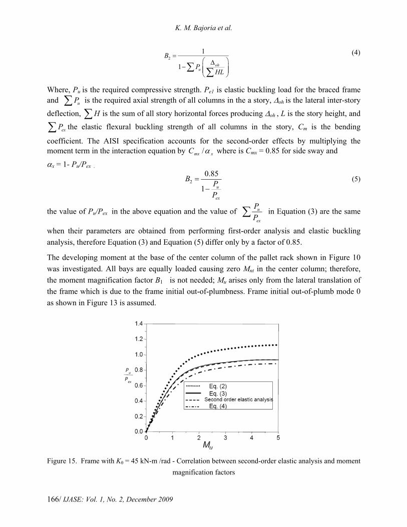
The developing moment at the base of the center column of the pallet rack shown in Figure 10 was investigated. All bays are equally loaded causing zero Mnt in the center column; therefore, the moment magnification factor B1 is not needed; Mu arises only from the lateral translation of the frame which is due to the frame initial out-of-plumbness. Frame initial out-of-plumb mode 0 as shown in Figure 13 is assumed.
Figure 15. Frame with Kθ = 45 kN-m /rad - Correlation between second-order elastic analysis and moment magnification factors

Stability Analysis of 3-D Conventional Pallet Rack Structures with Semi-Rigid Connections
IJASE: Vol. 1, No. 2, December 2009 / 167
Figure 16. Frame with Kθ = 70 kN-m /rad - Correlation between second-order elastic analysis and moment magnification factors
Figure 17. Frame with Kθ = 100 kN-m /rad. - Correlation between second-order elastic analysis and moment magnification factors
The relationship between Pu and Mu at the base of the center column obtained from second-order elastic analysis is used as a basis for evaluating Equations (2), (3), and (4). The results are given for four beams to column connection stiffnesses: Kθ = 45, 70, 100 kN-m /rad., and rigid as shown in Figures 15 through 18. As can be seen from these figures, equation (4) agrees better with the second-order elastic analysis than Equations (2) and (3) do. Equation (2) is slightly more conservative than the results from second-order elastic analysis and Equation (4), while Equation (3) is un-conservative compared with the results from second-order elastic analysis when used for semi-rigid frames. If the designer does not use second-order elastic analysis to obtain the required
K. M. Bajoria et al.
/ IJASE: Vol. 1, No. 2, December 2009 168
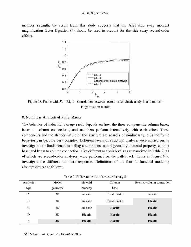
member strength, the result from this study suggests that the AISI side sway moment magnification factor Equation (4) should be used to account for the side sway second-order effects.
Figure 18. Frame with Kθ = Rigid - Correlation between second-order elastic analysis and moment
magnification factors 8. Nonlinear Analysis of Pallet Racks
The behavior of industrial storage racks depends on how the three components: column bases, beam to column connections, and members perform interactively with each other. These components and the slender nature of the structure are sources of nonlinearity, thus the frame behavior can become very complex. Different levels of structural analysis were carried out to investigate four fundamental modeling assumptions: model geometry, material property, column base, and beam to column connection. Five different analysis levels as summarized in Table 2, all of which are second-order analyses, were performed on the pallet rack shown in Figure10 to investigate the different nonlinear responses. Definitions of the four fundamental modeling assumptions are as follows:
Table 2. Different levels of structural analysis Analysis
type
Model
geometry
Material
Property
Column
base
Beam to column connection
A 3D Inelastic Fixed Elastic Inelastic
B 3D Inelastic Fixed Elastic Elastic
C 3D Inelastic Elastic Elastic
D 3D Elastic Elastic Elastic
E 2D Elastic Elastic Elastic
Stability Analysis of 3-D Conventional Pallet Rack Structures with Semi-Rigid Connections
IJASE: Vol. 1, No. 2, December 2009 / 169
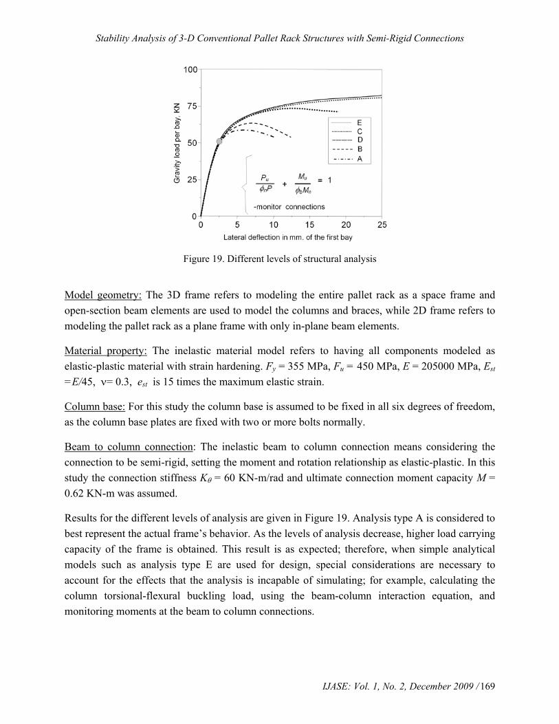
Figure 19. Different levels of structural analysis
Model geometry: The 3D frame refers to modeling the entire pallet rack as a space frame and open-section beam elements are used to model the columns and braces, while 2D frame refers to modeling the pallet rack as a plane frame with only in-plane beam elements.
Material property: The inelastic material model refers to having all components modeled as elastic-plastic material with strain hardening. Fy = 355 MPa, Fu = 450 MPa, E = 205000 MPa, Est =E/45, ν= 0.3, est is 15 times the maximum elastic strain.
Column base: For this study the column base is assumed to be fixed in all six degrees of freedom, as the column base plates are fixed with two or more bolts normally.
Beam to column connection: The inelastic beam to column connection means considering the connection to be semi-rigid, setting the moment and rotation relationship as elastic-plastic. In this study the connection stiffness Kθ = 60 KN-m/rad and ultimate connection moment capacity M = 0.62 KN-m was assumed.
Results for the different levels of analysis are given in Figure 19. Analysis type A is considered to best represent the actual frame’s behavior. As the levels of analysis decrease, higher load carrying capacity of the frame is obtained. This result is as expected; therefore, when simple analytical models such as analysis type E are used for design, special considerations are necessary to account for the effects that the analysis is incapable of simulating; for example, calculating the column torsional-flexural buckling load, using the beam-column interaction equation, and monitoring moments at the beam to column connections.

K. M. Bajoria et al.
/ IJASE: Vol. 1, No. 2, December 2009 170
9. Effective Length Approach for Cold-Formed Steel Frames
The effective length approach is used in many specifications and standards for steel frame design. The objective of this study was to compare the effective length approach and the finite element 3-D approach for accuracy and appropriateness for cold-formed steel frame and beam-column design. The storage rack industry currently uses the effective length approach. Design procedure of this effective length approach is as follows: 9.1. Effective Length Approach- Concentrically Loaded Compression Members
The column is considered to be a concentrically loaded compression member. The axial load carrying capacity of the member is determined according to the effective length approach using the following equation:
ncu PP φ= (6)
This approach relies significantly on the prediction of the critical buckling load of the member. The critical buckling load is usually determined by using the AISI torsional-flexural buckling provisions, or could be more accurately obtained by performing an elastic buckling analysis. Both procedures were investigated.
Approach 1a: The elastic buckling load was computed by using the AISI torsional-flexural buckling provisions with the value of Kx determined from the alignment chart and the values of Ky and Kt are assumed equal to 1 and 0.8, respectively.
Approach 1b: The elastic buckling load was computed by using the AISI torsional-flexural buckling provisions with the value of Kx determined more accurately from elastic flexural buckling analysis, and the value of Ky and Kt were assumed equal to 1 and 0.8, respectively. 9.2. Cold-Formed Steel Frames
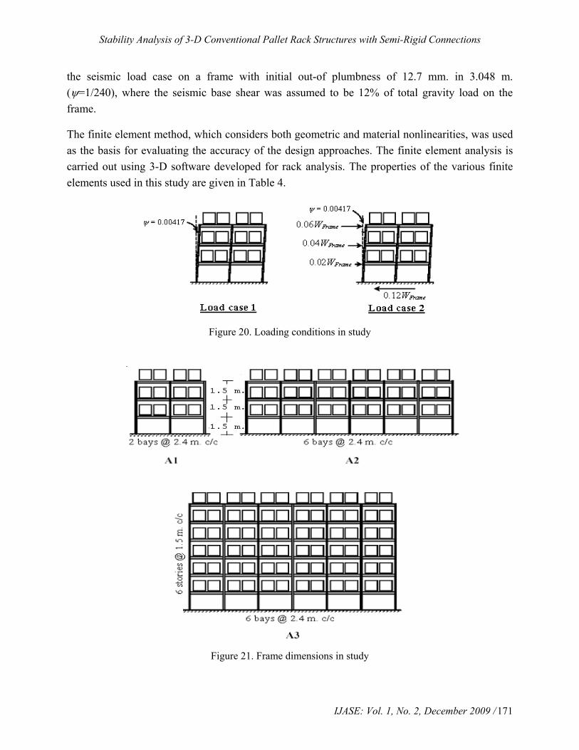
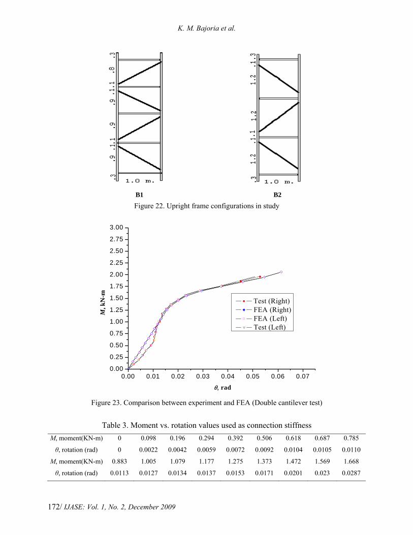
A parametric study was carried out to compare the effective length approach and the finite element method for accuracy and appropriateness for cold-formed steel frame design. Pallet racks as shown in Figure 21 were used as the vehicle for carrying out the parametric study. The parameters included: two load cases as shown in Figure 20, three frame dimensions as shown in Figure 21, two upright frame configurations as shown in Figure 23, eighteen upright sections shown in Table 1, one material yield stress (355 MPa), beam to upright connection stiffness obtained from double cantilever test as shown in Figure 23 and Table 3. These are given as real constants to combine 39 element, which acts as non-linear torsional spring, and braces and shelf beams as shown in Figures 11 and 12. Combinations of these parameters yielded a total of 108 pallet rack configurations for each load case. The first loading condition is the gravity load case on a frame with initial out-of plumbness of 12.7 mm in 3.048 m., the second loading condition is
Stability Analysis of 3-D Conventional Pallet Rack Structures with Semi-Rigid Connections
IJASE: Vol. 1, No. 2, December 2009 / 171
the seismic load case on a frame with initial out-of plumbness of 12.7 mm. in 3.048 m. (ψ=1/240), where the seismic base shear was assumed to be 12% of total gravity load on the frame.
The finite element method, which considers both geometric and material nonlinearities, was used as the basis for evaluating the accuracy of the design approaches. The finite element analysis is carried out using 3-D software developed for rack analysis. The properties of the various finite elements used in this study are given in Table 4.
Figure 20. Loading conditions in study
Figure 21. Frame dimensions in study
K. M. Bajoria et al.
/ IJASE: Vol. 1, No. 2, December 2009 172
B1 B2
Figure 22. Upright frame configurations in study
0.00 0.01 0.02 0.03 0.04 0.05 0.06 0.070.00
0.25
0.50
0.75
1.00
1.25
1.50
1.75
2.00
2.25
2.50
2.75
3.00
M, k
N-m
θ, rad
Test (Right) FEA (Right) FEA (Left) Test (Left)
Figure 23. Comparison between experiment and FEA (Double cantilever test)
Table 3. Moment vs. rotation values used as connection stiffness
M, moment(KN-m) 0 0.098 0.196 0.294 0.392 0.506 0.618 0.687 0.785
θ, rotation (rad) 0 0.0022 0.0042 0.0059 0.0072 0.0092 0.0104 0.0105 0.0110
M, moment(KN-m) 0.883 1.005 1.079 1.177 1.275 1.373 1.472 1.569 1.668
θ, rotation (rad) 0.0113 0.0127 0.0134 0.0137 0.0153 0.0171 0.0201 0.023 0.0287

Stability Analysis of 3-D Conventional Pallet Rack Structures with Semi-Rigid Connections
IJASE: Vol. 1, No. 2, December 2009 / 173
Table 4. Properties of the finite elements used in frame analysis in brief
Element name
Beam24
Combin39
Beam4
Link8
Position of connector Element
Upright Beam-upright connector Beam Horizontal and
Bracing
Description 3-D Thin walled Beam element
Non-Linear Spring element
3-D Elastic Beam element
3-D Spar (truss) element
Number of nodes 3 2 3 2
Degrees of Freedom
x, y, and z translational and
rotational displacements
x, y, and z translational,
rotational displacements and
temperature
x, y, and z translational and
rotational displacements
x, y, and z translational
displacements
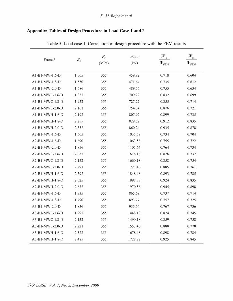
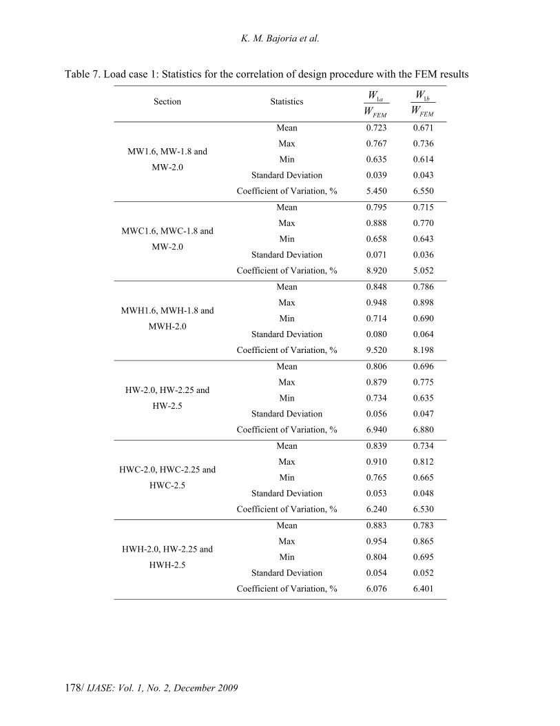
The correlations between the design approaches and the finite element results are given in Tables 5 and 6 (Few representative sample result) and a statistical summary of all results given in Tables 7 and 8 in Appendix, where W1a, and W1b are the ultimate load carrying capacity per bay of the frame obtained by using the Approaches 1a, and 1b, respectively. WFEM is the ultimate load carrying capacity per bay of the frame obtained by using the finite element method. In practice, the resistance factor φc is equal to 0.85, and φb is equal to 0.90 or 0.95; these values are, however, for research purposes in this study all assumed equal to one.
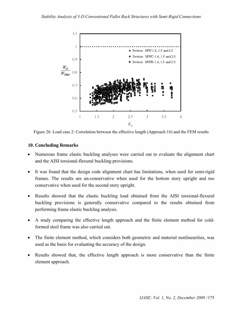
The results for load case 1, which are also plotted in Figures 24 through 26 where the finite element analysis was used as the basis for evaluating the accuracy of the different design approaches. As can be seen in these figures, Approach 1b, is conservative compared to the finite element results while Approach 1a has a few un-conservative designs. The reason why these few results in Approach 1a are un-conservative compared to the finite element results is because the second-order effects arising from the frame story-out-plumbness was considered in the design process (Approach 1b) and the FEM results.

K. M. Bajoria et al.
/ IJASE: Vol. 1, No. 2, December 2009 174
Figure 24. Load case 1: Correlation between the effective length approach (Approach 1a) and the FEM
results
Figure 25. Load case 1: Correlation between the effective length approach (Approach 1b) and the FEM
results
Stability Analysis of 3-D Conventional Pallet Rack Structures with Semi-Rigid Connections
IJASE: Vol. 1, No. 2, December 2009 / 175
Figure 26. Load case 2: Correlation between the effective length (Approach 1b) and the FEM results
10. Concluding Remarks
• Numerous frame elastic buckling analyses were carried out to evaluate the alignment chart and the AISI torsional-flexural buckling provisions.
• It was found that the design code alignment chart has limitations, when used for semi-rigid frames. The results are un-conservative when used for the bottom story upright and too conservative when used for the second story upright.
• Results showed that the elastic buckling load obtained from the AISI torsional-flexural buckling provisions is generally conservative compared to the results obtained from performing frame elastic buckling analysis.
• A study comparing the effective length approach and the finite element method for cold-formed steel frame was also carried out.
• The finite element method, which considers both geometric and material nonlinearities, was used as the basis for evaluating the accuracy of the design.
• Results showed that, the effective length approach is more conservative than the finite element approach.
K. M. Bajoria et al.
/ IJASE: Vol. 1, No. 2, December 2009 176
Appendix: Tables of Design Procedure in Load Case 1 and 2
Table 5. Load case 1: Correlation of design procedure with the FEM results
Frame* Kx Fy
(MPa)
WFEM
(kN) FEM
a
WW1
FEM
c
WW1
A1-B1-MW-1.6-D 1.505 355 459.92 0.718 0.604
A1-B1-MW-1.8-D 1.550 355 471.64 0.735 0.612
A1-B1-MW-2.0-D 1.686 355 489.56 0.755 0.634
A1-B1-MWC-1.6-D 1.855 355 709.22 0.832 0.699
A1-B1-MWC-1.8-D 1.952 355 727.22 0.855 0.714
A1-B1-MWC-2.0-D 2.161 355 754.34 0.876 0.721
A1-B1-MWH-1.6-D 2.192 355 807.92 0.899 0.735
A1-B1-MWH-1.8-D 2.255 355 829.52 0.912 0.835
A1-B1-MWH-2.0-D 2.352 355 860.24 0.935 0.878
A2-B1-MW-1.6-D 1.605 355 1035.59 0.734 0.704
A2-B1-MW-1.8-D 1.690 355 1063.58 0.755 0.722
A2-B1-MW-2.0-D 1.856 355 1105.64 0.764 0.734
A2-B1-MWC-1.6-D 2.055 355 1618.18 0.826 0.732
A2-B1-MWC-1.8-D 2.152 355 1660.18 0.858 0.754
A2-B1-MWC-2.0-D 2.291 355 1723.46 0.885 0.761
A2-B1-MWH-1.6-D 2.392 355 1848.48 0.893 0.785
A2-B1-MWH-1.8-D 2.525 355 1898.88 0.924 0.835
A2-B1-MWH-2.0-D 2.632 355 1970.56 0.945 0.898
A3-B1-MW-1.6-D 1.735 355 865.68 0.737 0.714
A3-B1-MW-1.8-D 1.790 355 893.77 0.757 0.725
A3-B1-MW-2.0-D 1.836 355 935.64 0.767 0.736
A3-B1-MWC-1.6-D 1.995 355 1448.18 0.824 0.745
A3-B1-MWC-1.8-D 2.152 355 1490.18 0.859 0.758
A3-B1-MWC-2.0-D 2.221 355 1553.46 0.888 0.770
A3-B1-MWH-1.6-D 2.322 355 1678.48 0.898 0.784
A3-B1-MWH-1.8-D 2.485 355 1728.88 0.925 0.845

Stability Analysis of 3-D Conventional Pallet Rack Structures with Semi-Rigid Connections
IJASE: Vol. 1, No. 2, December 2009 / 177
Table 6. Load case 2: Correlation of design procedure with the FEM results
Frame* Kx Fy
(MPa)
WFEM
(kN) FEM
a
WW1
FEM
c
WW1
A1-B1-MW-1.6-D 1.605 355 299.16 0.604 0.535
A1-B1-MW-1.8-D 1.621 355 311.37 0.615 0.548
A1-B1-MW-2.0-D 1.695 355 329.56 0.635 0.559
A1-B1-MWC-1.6-D 1.716 355 549.22 0.643 0.578
A1-B1-MWC-1.8-D 1.795 355 567.22 0.658 0.591
A1-B1-MWC-2.0-D 1.835 355 594.34 0.669 0.615
A1-B1-MWH-1.6-D 1.875 355 647.92 0.679 0.635
A1-B1-MWH-1.8-D 1.914 355 669.52 0.691 0.643
A1-B1-MWH-2.0-D 1.985 355 700.24 0.699 0.663
A2-B1-MW-1.6-D 1.713 355 865.38 0.609 0.539
A2-B1-MW-1.8-D 1.728 355 893.49 0.617 0.551
A2-B1-MW-2.0-D 1.824 355 935.64 0.636 0.560
A2-B1-MWC-1.6-D 1.915 355 1448.18 0.648 0.581
A2-B1-MWC-1.8-D 1.924 355 1490.18 0.661 0.592
A2-B1-MWC-2.0-D 1.937 355 1553.46 0.673 0.620
A2-B1-MWH-1.6-D 2.155 355 1678.48 0.676 0.639
A2-B1-MWH-1.8-D 2.212 355 1728.88 0.693 0.648
A2-B1-MWH-2.0-D 2.332 355 1800.56 0.710 0.670
A3-B1-MW-1.6-D 1.801 355 639.33 0.613 0.545
A3-B1-MW-1.8-D 1.824 355 667.67 0.619 0.561
A3-B1-MW-2.0-D 1.839 355 709.64 0.641 0.569
A3-B1-MWC-1.6-D 1.915 355 1222.18 0.651 0.588
A3-B1-MWC-1.8-D 1.938 355 1264.18 0.669 0.599
A3-B1-MWC-2.0-D 2.108 355 1327.46 0.680 0.631
K. M. Bajoria et al.
/ IJASE: Vol. 1, No. 2, December 2009 178
Table 7. Load case 1: Statistics for the correlation of design procedure with the FEM results
Section Statistics FEM
a
WW1
FEM
b
WW1
MW1.6, MW-1.8 and
MW-2.0
Mean 0.723 0.671
Max 0.767 0.736
Min 0.635 0.614
Standard Deviation 0.039 0.043
Coefficient of Variation, % 5.450 6.550
MWC1.6, MWC-1.8 and
MW-2.0
Mean 0.795 0.715
Max 0.888 0.770
Min 0.658 0.643
Standard Deviation 0.071 0.036
Coefficient of Variation, % 8.920 5.052
MWH1.6, MWH-1.8 and
MWH-2.0
Mean 0.848 0.786
Max 0.948 0.898
Min 0.714 0.690
Standard Deviation 0.080 0.064
Coefficient of Variation, % 9.520 8.198
HW-2.0, HW-2.25 and
HW-2.5
Mean 0.806 0.696
Max 0.879 0.775
Min 0.734 0.635
Standard Deviation 0.056 0.047
Coefficient of Variation, % 6.940 6.880
HWC-2.0, HWC-2.25 and
HWC-2.5
Mean 0.839 0.734
Max 0.910 0.812
Min 0.765 0.665
Standard Deviation 0.053 0.048
Coefficient of Variation, % 6.240 6.530
HWH-2.0, HW-2.25 and
HWH-2.5
Mean 0.883 0.783
Max 0.954 0.865
Min 0.804 0.695
Standard Deviation 0.054 0.052
Coefficient of Variation, % 6.076 6.401

Stability Analysis of 3-D Conventional Pallet Rack Structures with Semi-Rigid Connections
IJASE: Vol. 1, No. 2, December 2009 / 179
Table 8. Load case 2: Statistics for the correlation of design procedure with the FEM results
Section Statistics FEM
a
WW1
FEM
b
WW1
MW1.6, MW-1.8 and
MW-2.0
Mean 0.592 0.536
Max 0.641 0.569
Min 0.545 0.512
Standard Deviation 0.032 0.018
Coefficient of Variation, % 5.405 3.358
MWC1.6, MWC-1.8 and
MW-2.0
Mean 0.624 0.575
Max 0.68 0.631
Min 0.579 0.535
Standard Deviation 0.039 0.029
Coefficient of Variation, % 6.25 5.043
MWH1.6, MWH-1.8 and
MWH-2.0
Mean 0.656 0.617
Max 0.72 0.683
Min 0.599 0.568
Standard Deviation 0.042 0.039
Coefficient of Variation, % 6.402 6.321
HW-2.0, HW-2.25 and
HW-2.5
Mean 0.569 0.533
Max 0.59 0.549
Min 0.545 0.515
Standard Deviation 0.013 0.011
Coefficient of Variation, % 2.285 2.063
HWC-2.0, HWC-2.25 and
HWC-2.5
Mean 0.596 0.5626
Max 0.619 0.584
Min 0.573 0.538
Standard Deviation 0.014 0.013
Coefficient of Variation, % 2.348 2.311
HWH-2.0, HW-2.25 and
HWH-2.5
Mean 0.631 0.594
Max 0.648 0.621
Min 0.614 0.564
Standard Deviation 0.011 0.015
Coefficient of Variation, % 1.743 2.525

K. M. Bajoria et al.
/ IJASE: Vol. 1, No. 2, December 2009 180
References
Abdel-Jaber, M., Beale, R.G. and Godley, M.H.R. (2006), “A theoretical and experimental investigation of pallet rack structures under sway”, Journal of Construction Steel Research, Vol. 62, Pages 68-80.
Abdel-Jaber, M., Beale, R.G. and Godley, M.H.R. (2005), “Numerical study on semi-rigid racking frame under sway”, Journal of Computers and Structures, Vol. 83, Pages 2463-2475.
American Iron and Steel Institute (2001), “North American Specification for the Design of Cold-Formed Steel Structural Members”, Washington, DC., USA.
Bajoria, K.M. and Talikoti, R.S. (2006), “Determination of fexibility of beam-to-column connectors used in thin walled cold-formed steel pallet racking systems”, Journal of Thin-Walled Structures, Vol. 44, Pages 372-380.
Beale, R.G. and Godley, M.H.R. (2004), “Sway analysis of spliced pallet rack structures” Journal of Computers and Structures, Vol. 83, Pages 2145-2146.
Chen, J. and Young, B. (2007), “Experimental investigation of cold formed steel material at elevated temperatures”, Journal of Thin-Walled Structures, Vol. 45, Pages 96-110.
Davies, J.M. (1992), “Down aisle stability of rack structures”, 11th International Specialty Conference on Cold-Formed Steel Structures, St. Louis, MO, USA., Pages 417-435.
Godley, M.H.R., Beale, R.G. and Feng, X. (2000), “Analysis and design of down aisle pallet rack structures”, Journal of Computers and Structures, Vol. 77, Pages 391-401.
Haris, E. and Hancock, G.J. (2002), “Sway stability testing of high rise rack subassemblies”, 16th International Specialty Conference on Cold-Formed Steel Structures, Orlando, Fl., USA., Pages 385-396.
Lewis, G.M. (1997), “Imperfection sensitivity of structures with semi-rigid joints”, Journal of Thin-Walled Structures, Vol. 27, Pages 187-201.
Teh, L.H., Hancock, G.J. and Clarke, M.J. (2004), “Analysis and design of double-sided high-rise steel pallet rack frames”, ASCE Journal of Structural Engineering, Vol. 130, Pages 1011 -1020.
RMI Specification for the Design (2005), “Testing and Utilization of Industrial Steel Storage Racks”, Rack Manufacturers Institute, Charlotte, NC., USA.
Rhodes, J. (1991), “Design of Cold-Formed Steel Members”, Elsevier Applied Science, London, UK.
Stability Analysis of 3-D Conventional Pallet Rack Structures with Semi-Rigid Connections
IJASE: Vol. 1, No. 2, December 2009 / 181
Salmon, C.G, and Johnson, J.E. (1996), “Steel Structures; Design and Behavior”, 4th edition, Harper Collins College Publishers, New York, NY., USA.
Standard Australia –SA (1993), “Steel Storage Racking; AS 4084-1993”, Homebush, New South Wales, Australia.
SEMA (1985), “Code of Practice for the Design of Static Racking”, The Storage Equipment Manufacturer’s Association, Birmingham, UK.
Timoshenko, S.P. (1961), “Theory of Elastic Stability”, Mc.Graw Hill Book Company, New York, NY., USA.
Young, B. and Rasmussen, K.J.R. (1999), “Behaviour of cold-formed singly symmetric columns”, Journal of Thin-Walled Structures, Vol. 33, Pages 83–102.
Young, B. and Rasmussen, K.J.R. (1999), “Shift of effective centroid of channel column”, ASCE Journal of Structural Engineering, Vol. 125, Pages 524–531.
Young, B. (2008a), “Research on cold formed steel columns”, Journal of Thin-Walled Structures, Vol. 46, Pages 731-740.
Young, B. and Chen, J. (2008b), “Design of cold-formed steel built up closed sections with intermediate stiffeners”, ASCE Journal of Structural Engineering, Vol. 134, Pages 727-737.