stability analysis for the right abutment … · typical fracture: planar shape; smooth surface;...
TRANSCRIPT
BUILDING STRONG®and Taking Care of People!
“The views, opinions and findings contained in this report are those of the authors(s) and should not be construed as an official Department of the Army position, policy or decision, unless so designated by other official documentation.”“The views, opinions and findings contained in this report are those of the authors(s) and should not be construed as an official Department of the Army position, policy or decision, unless so designated by other official documentation.”
1File Name
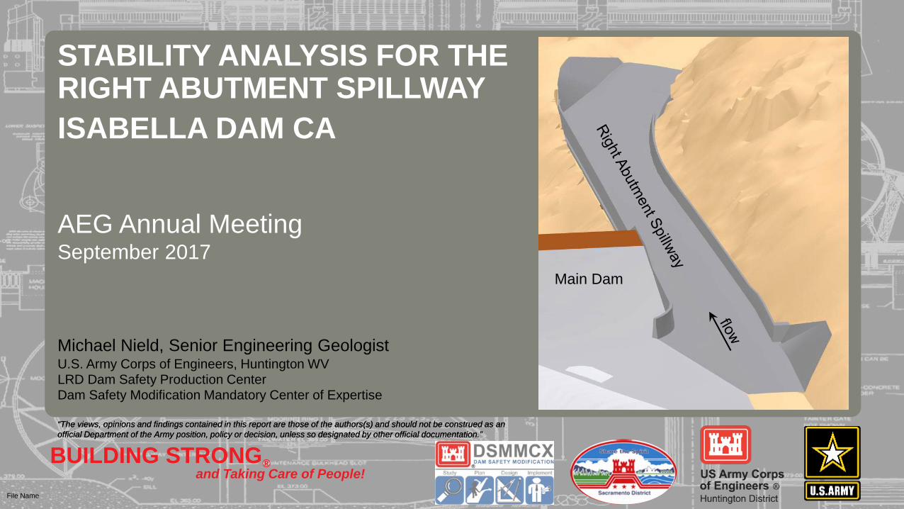
Michael Nield, Senior Engineering GeologistU.S. Army Corps of Engineers, Huntington WVLRD Dam Safety Production CenterDam Safety Modification Mandatory Center of Expertise
STABILITY ANALYSIS FOR THE RIGHT ABUTMENT SPILLWAY ISABELLA DAM CA
AEG Annual MeetingSeptember 2017
Main Dam

BUILDING STRONG®and Taking Care of People!2
Stability Analysis for the Right Abutment Spillway – Isabella Dam, CAOUTLINE
A. PROJECT INFORMATION
B. SPILLWAY STABILITY
C. CUT-SLOPE STABILITY
1. Project Location2. Project Description3. Site Geology
1. Founding Elevations2. Plane Analysis3. Wedge Analysis
1. Stereonet Analysis2. Construction Concerns
BUILDING STRONG®and Taking Care of People!3
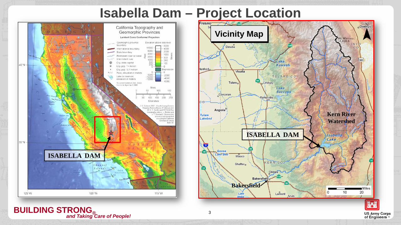
Isabella Dam – Project LocationVicinity Map
ISABELLA DAM
Kern RiverWatershed
ISABELLA DAM
Bakersfield
BUILDING STRONG®and Taking Care of People!
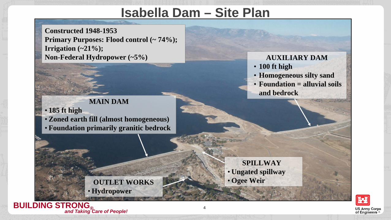
Isabella Dam – Site Plan
4
MAIN DAM• 185 ft high• Zoned earth fill (almost homogeneous)• Foundation primarily granitic bedrock
AUXILIARY DAM• 100 ft high• Homogeneous silty sand • Foundation = alluvial soils
and bedrock
SPILLWAY• Ungated spillway• Ogee Weir
Constructed 1948-1953Primary Purposes: Flood control (~ 74%); Irrigation (~21%); Non-Federal Hydropower (~5%)
OUTLET WORKS• Hydropower
BUILDING STRONG®and Taking Care of People!
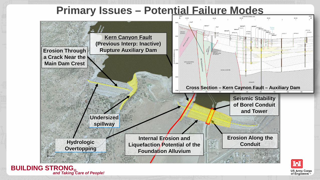
Erosion Along the Conduit
Erosion Through a Crack Near the Main Dam Crest
Undersized spillway
Hydrologic Overtopping
Seismic Stability of Borel Conduit
and Tower
Kern Canyon Fault (Previous Interp: Inactive)
Rupture Auxiliary Dam
Internal Erosion and Liquefaction Potential of the
Foundation Alluvium
Cross Section – Kern Caynon Fault – Auxiliary Dam
Primary Issues – Potential Failure Modes
BUILDING STRONG®and Taking Care of People!
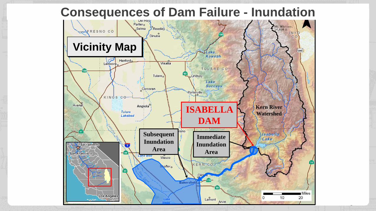
Vicinity Map
ISABELLA DAM
Kern RiverWatershed
ImmediateInundation
Area
SubsequentInundation
Area
Consequences of Dam Failure - Inundation
BUILDING STRONG®and Taking Care of People!7
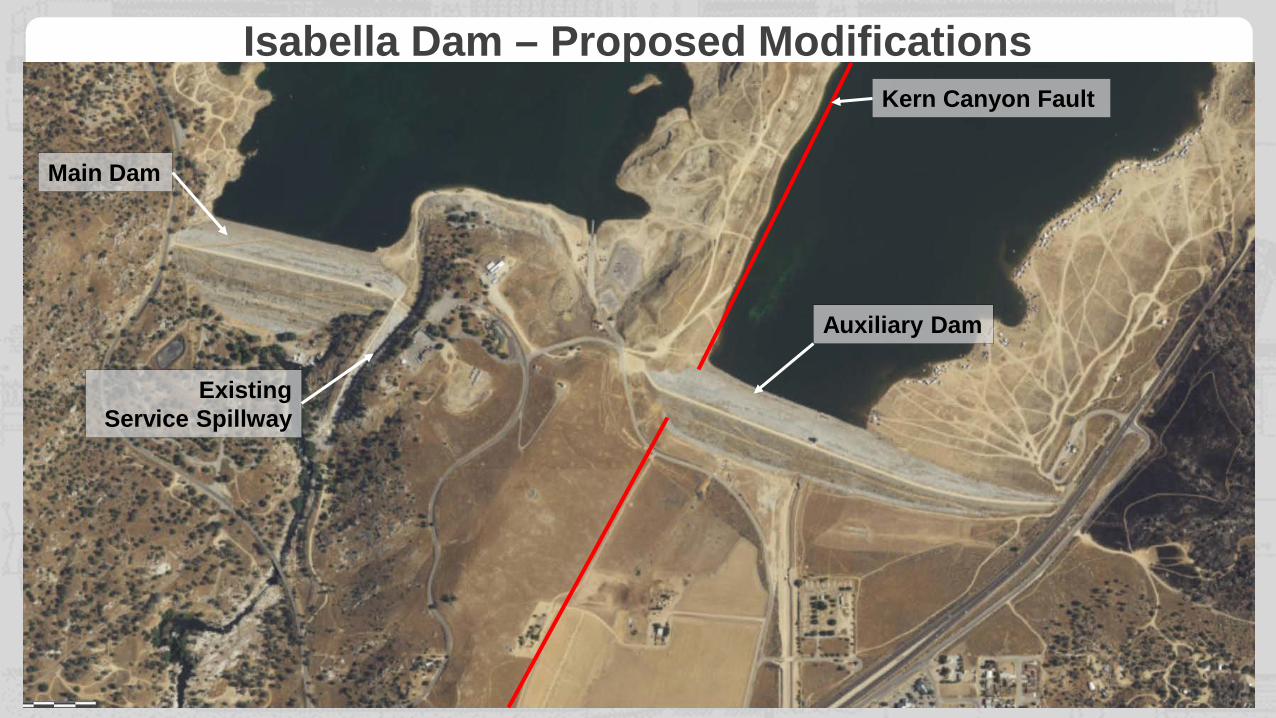
Isabella Dam – Proposed Modifications
Auxiliary Dam
Kern Canyon Fault
Main Dam
ExistingService Spillway
BUILDING STRONG®and Taking Care of People!8
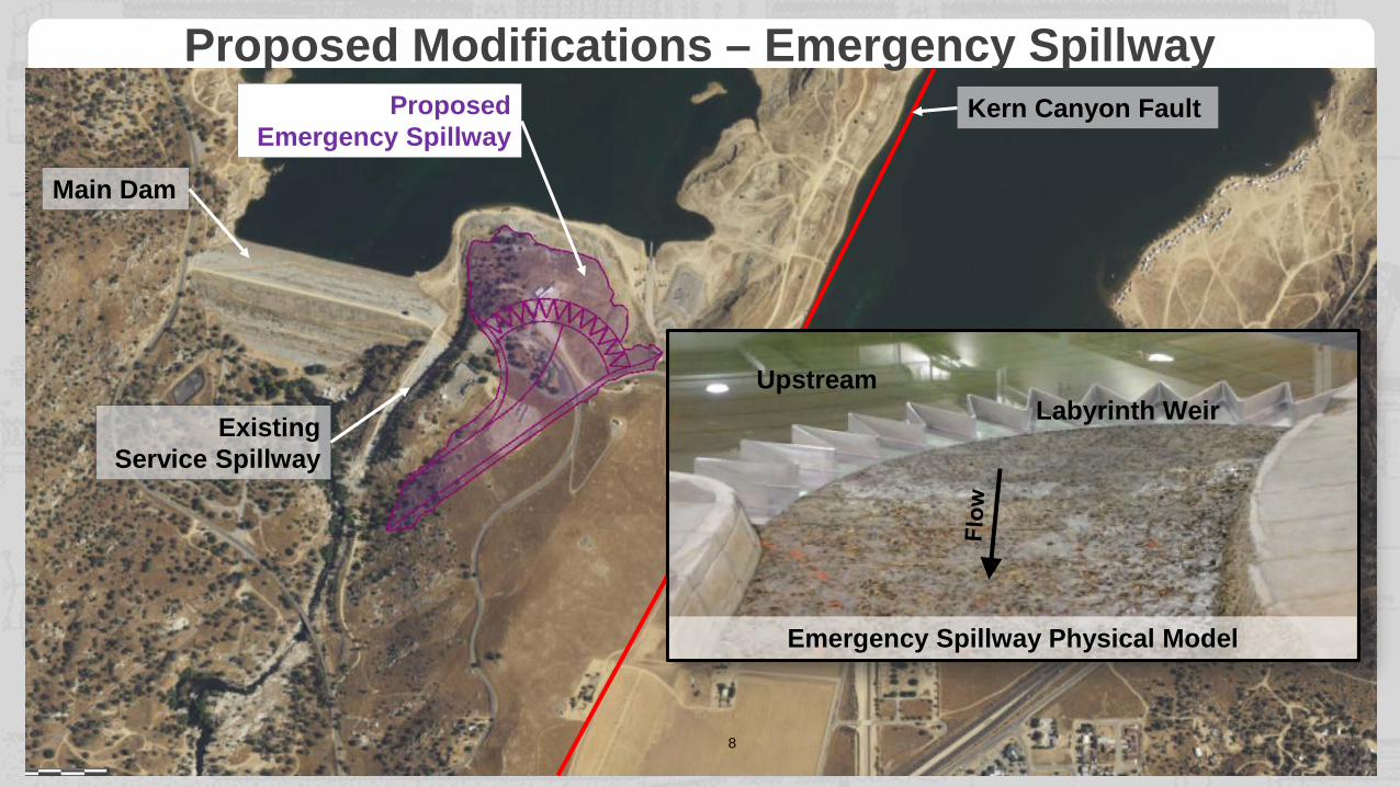
Main Dam
Auxiliary Dam
ExistingService Spillway
Kern Canyon FaultProposed Emergency Spillway
UpstreamLabyrinth Weir
Emergency Spillway Physical Model
Proposed Modifications – Emergency Spillway
BUILDING STRONG®and Taking Care of People!9
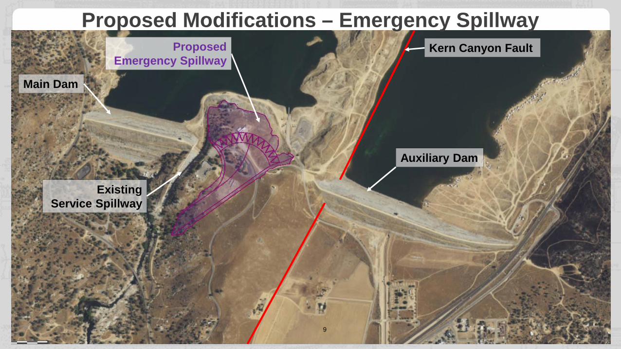
Main Dam
Auxiliary Dam
ExistingService Spillway
Kern Canyon FaultProposed Emergency Spillway
Proposed Modifications – Emergency Spillway
BUILDING STRONG®and Taking Care of People!10
Auxiliary Dam
Kern Canyon Fault
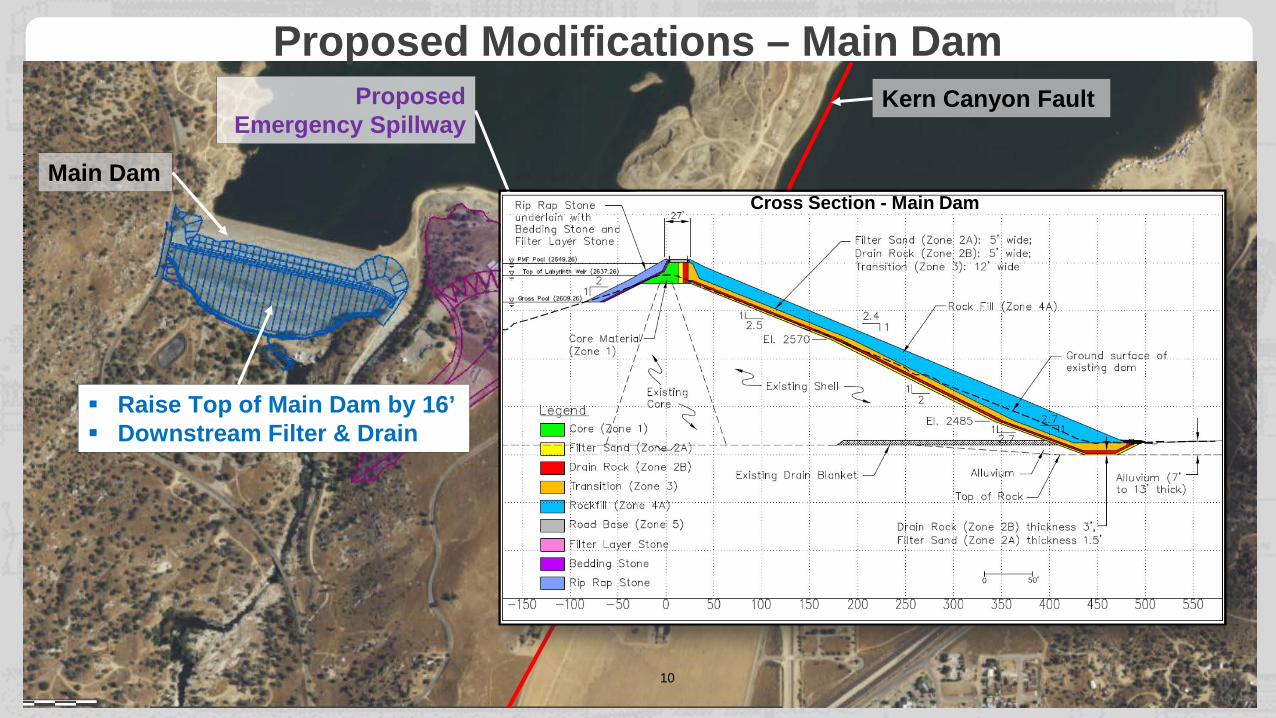
Raise Top of Main Dam by 16’ Downstream Filter & Drain
Proposed Emergency Spillway
Main DamCross Section - Main Dam
Proposed Modifications – Main Dam
BUILDING STRONG®and Taking Care of People!11
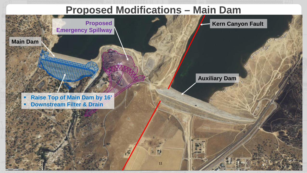
Auxiliary Dam
Kern Canyon FaultProposed Emergency Spillway
Main Dam
Raise Top of Main Dam by 16’ Downstream Filter & Drain
Proposed Modifications – Main Dam
BUILDING STRONG®and Taking Care of People!12
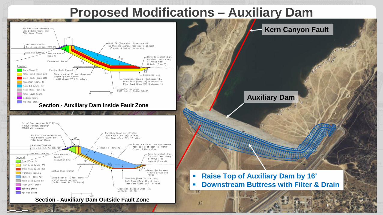
Auxiliary Dam
Kern Canyon Fault
Raise Top of Auxiliary Dam by 16’ Downstream Buttress with Filter & Drain
Raise Top of Main Dam by 16’ Downstream Filter & Drain
Proposed Emergency Spillway
Main Dam
Section - Auxiliary Dam Inside Fault Zone
Section - Auxiliary Dam Outside Fault Zone
Proposed Modifications – Auxiliary Dam
BUILDING STRONG®and Taking Care of People!13
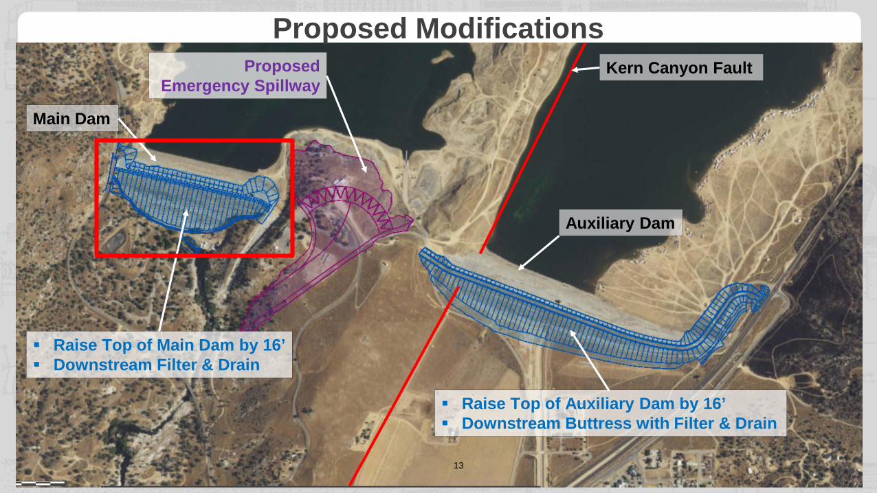
Auxiliary Dam
Kern Canyon Fault
Raise Top of Auxiliary Dam by 16’ Downstream Buttress with Filter & Drain
Raise Top of Main Dam by 16’ Downstream Filter & Drain
Proposed Emergency Spillway
Main Dam
Proposed Modifications
BUILDING STRONG®and Taking Care of People!14
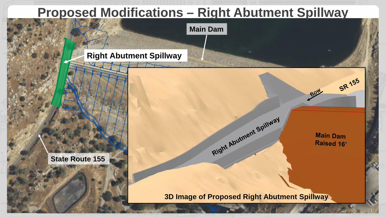
Main Dam
Existing Service Spillway
State Route 155
Right Abutment Spillway
3D Image of Proposed Right Abutment Spillway
Proposed Modifications – Right Abutment Spillway
BUILDING STRONG®and Taking Care of People!15
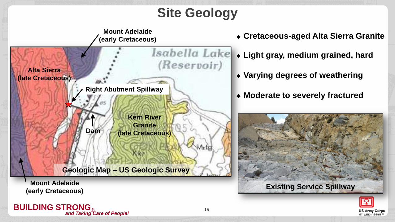
Site Geology Cretaceous-aged Alta Sierra Granite
Varying degrees of weatheringAlta Sierra (late Cretaceous)
Kern River Granite
(late Cretaceous)
Mount Adelaide (early Cretaceous)
Mount Adelaide (early Cretaceous)
Dam
Right Abutment Spillway Moderate to severely fractured
Light gray, medium grained, hard
Existing Service Spillway
Geologic Map – US Geologic Survey
BUILDING STRONG®and Taking Care of People!16
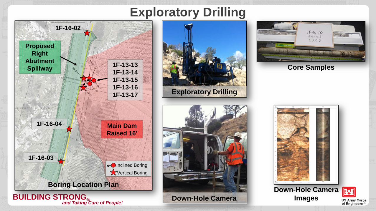
Exploratory Drilling
Main DamRaised 16’
1F-13-13 1F-13-14 1F-13-15 1F-13-16 1F-13-17
1F-16-03
1F-16-04
1F-16-02
Proposed Right
Abutment Spillway
Boring Location Plan
Inclined BoringVertical Boring
Core Samples
Down-Hole Camera Images
Exploratory Drilling
Down-Hole Camera
BUILDING STRONG®and Taking Care of People!17
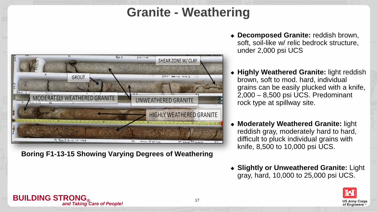
Granite - Weathering Decomposed Granite: reddish brown,
soft, soil-like w/ relic bedrock structure, under 2,000 psi UCS
Moderately Weathered Granite: light reddish gray, moderately hard to hard, difficult to pluck individual grains with knife, 8,500 to 10,000 psi UCS.
Slightly or Unweathered Granite: Light gray, hard, 10,000 to 25,000 psi UCS.
Highly Weathered Granite: light reddish brown, soft to mod. hard, individual grains can be easily plucked with a knife, 2,000 – 8,500 psi UCS. Predominant rock type at spillway site.
Boring F1-13-15 Showing Varying Degrees of Weathering
BUILDING STRONG®and Taking Care of People!18
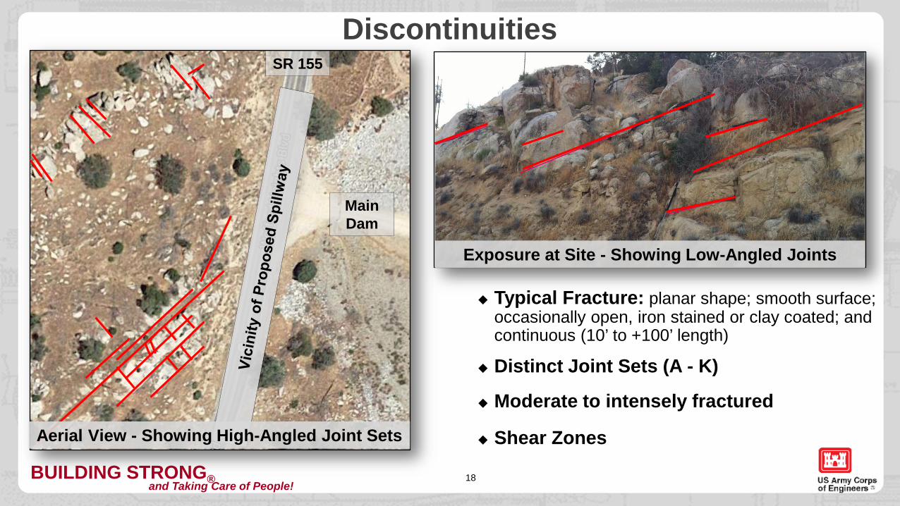
Discontinuities
Moderate to intensely fractured
Typical Fracture: planar shape; smooth surface; occasionally open, iron stained or clay coated; and continuous (10’ to +100’ length)
Distinct Joint Sets (A - K)
Shear Zones
Main Dam
SR 155
Exposure at Site - Showing Low-Angled Joints
Aerial View - Showing High-Angled Joint Sets

BUILDING STRONG®and Taking Care of People!19
Stability Analysis for the Right Abutment Spillway – Isabella Dam, CAOUTLINE
A. PROJECT INFORMATION
B. SPILLWAY STABILITY
C. CUT-SLOPE STABILITY
1. Project Location2. Project Description3. Site Geology
1. Founding Elevations2. Plane Analysis3. Wedge Analysis
1. Stereonet Analysis2. Construction Concerns
BUILDING STRONG®and Taking Care of People! 20
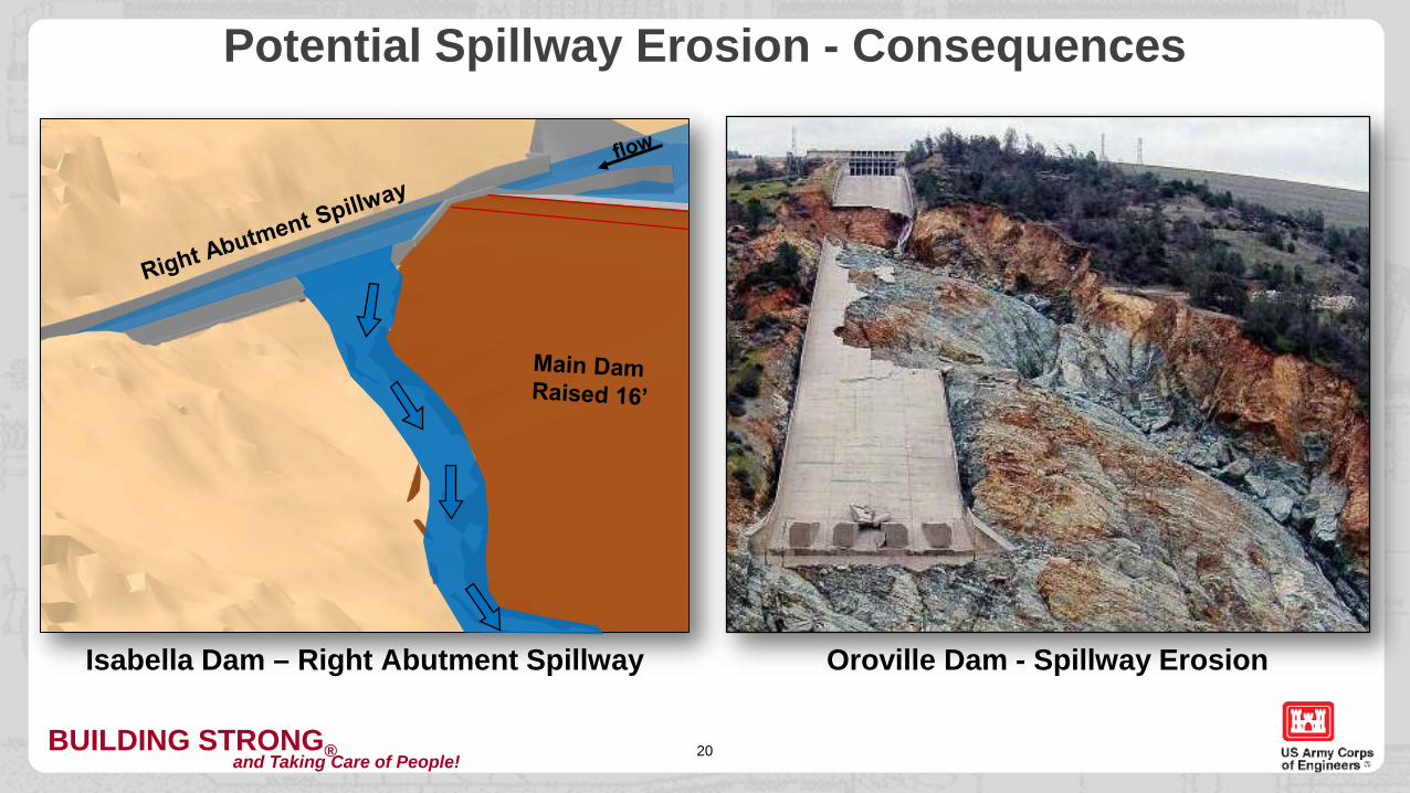
Potential Spillway Erosion - Consequences
Oroville Dam - Spillway ErosionIsabella Dam – Right Abutment Spillway
BUILDING STRONG®and Taking Care of People!21
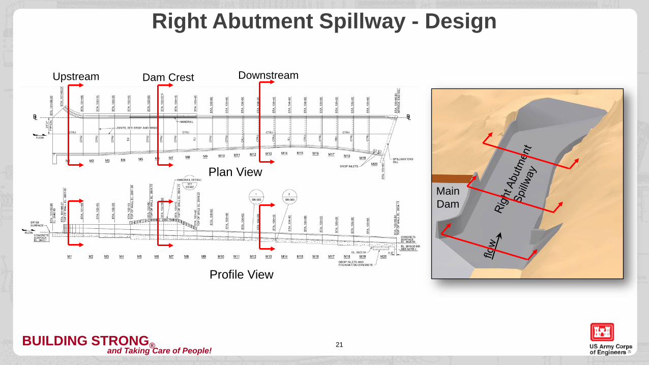
Right Abutment Spillway - Design
MainDam
Plan View
Profile View
Upstream Dam Crest Downstream
BUILDING STRONG®and Taking Care of People! 22
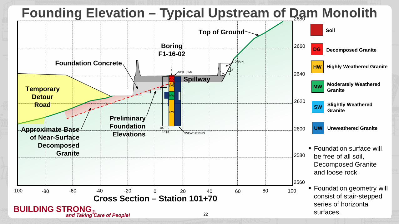
Founding Elevation – Typical Upstream of Dam Monolith2680
2660
2640
2620
2600
2580
2560
0-20-40-60-80-100 20 40 60 80 100
HW
HW
MW
DG
SOIL (SM)
Boring F1-16-02
0100RQD WEATHERING
Temporary Detour Road
Foundation Concrete
DG Decomposed Granite
HW Highly Weathered Granite
MW Moderately Weathered Granite
SW Slightly Weathered Granite
UW Unweathered Granite
Soil
21
Cross Section – Station 101+70
Approximate Base of Near-Surface
Decomposed Granite
Foundation surface will be free of all soil, Decomposed Granite and loose rock.
Foundation geometry will consist of stair-stepped series of horizontalsurfaces.
DRAIN
Spillway
Top of Ground
Preliminary Foundation Elevations
BUILDING STRONG®and Taking Care of People! 23
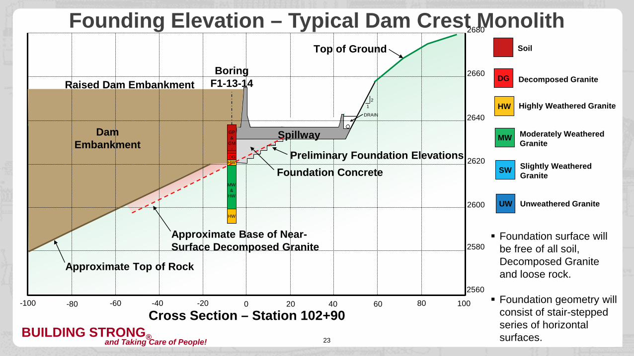
Founding Elevation – Typical Dam Crest Monolith2680
2660
2640
2620
2600
2580
2560
0-20-40-60-80-100 20 40 60 80 100
SP
Boring F1-13-14
Foundation Concrete
DG Decomposed Granite
HW Highly Weathered Granite
MW Moderately Weathered Granite
SW Slightly Weathered Granite
UW Unweathered Granite
Soil
21
Cross Section – Station 102+90
Approximate Base of Near-Surface Decomposed Granite
Foundation surface will be free of all soil, Decomposed Granite and loose rock.
Foundation geometry will consist of stair-stepped series of horizontalsurfaces.
DRAIN
Top of Ground
Dam Embankment
Approximate Top of Rock
Spillway
HW
HW
MW&
HW
DG
GP&
GM
Raised Dam Embankment
Preliminary Foundation Elevations
BUILDING STRONG®and Taking Care of People! 24
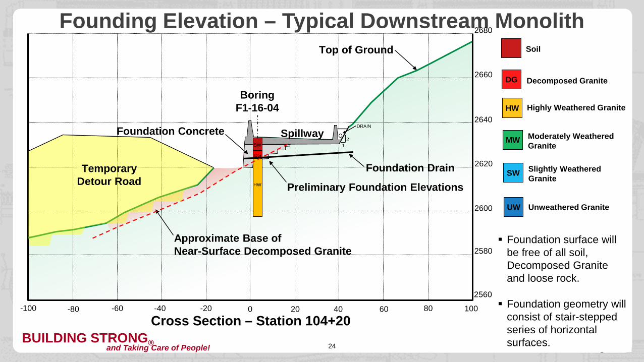
Founding Elevation – Typical Downstream Monolith2680
2660
2640
2620
2600
2580
2560
0-20-40-60-80-100 20 40 60 80 100
Boring F1-16-04
Foundation Concrete
DG Decomposed Granite
HW Highly Weathered Granite
MW Moderately Weathered Granite
SW Slightly Weathered Granite
UW Unweathered Granite
Soil
21
Cross Section – Station 104+20
Approximate Base ofNear-Surface Decomposed Granite
Foundation surface will be free of all soil, Decomposed Granite and loose rock.
Foundation geometry will consist of stair-stepped series of horizontalsurfaces.
DRAIN
Top of Ground
Foundation Drain
Spillway
HW
DG
SW
Temporary Detour Road Preliminary Foundation Elevations
BUILDING STRONG®and Taking Care of People!25
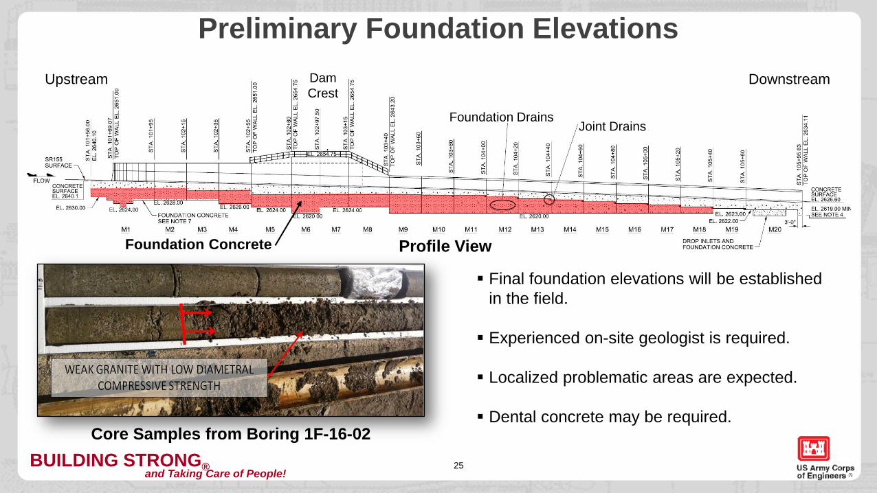
Preliminary Foundation ElevationsUpstream
Foundation Concrete Profile View
DownstreamDam Crest
Foundation DrainsJoint Drains
Core Samples from Boring 1F-16-02
Final foundation elevations will be established in the field.
Experienced on-site geologist is required.
Localized problematic areas are expected.
Dental concrete may be required.
BUILDING STRONG®and Taking Care of People!26
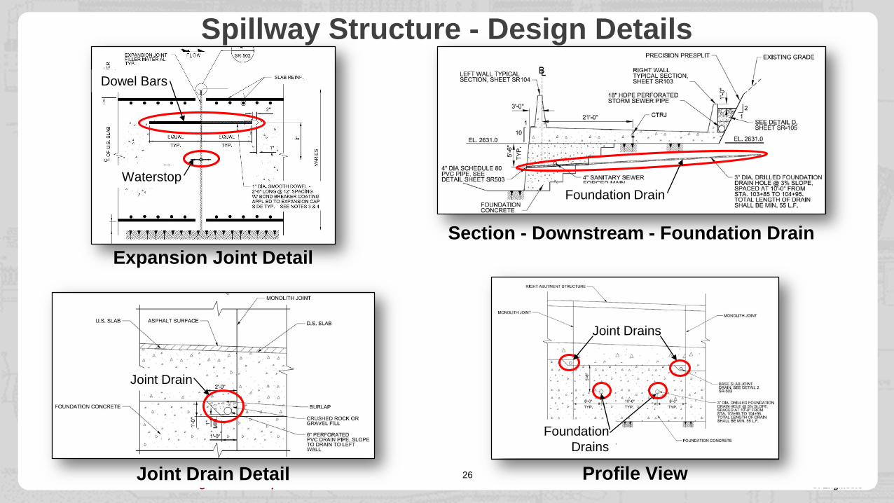
Spillway Structure - Design Details
Expansion Joint DetailSection - Downstream - Foundation Drain
Joint Drain Detail Profile View
Waterstop
Dowel Bars
Joint Drain
Foundation Drain
Foundation Drains
Joint Drains
BUILDING STRONG®and Taking Care of People!27
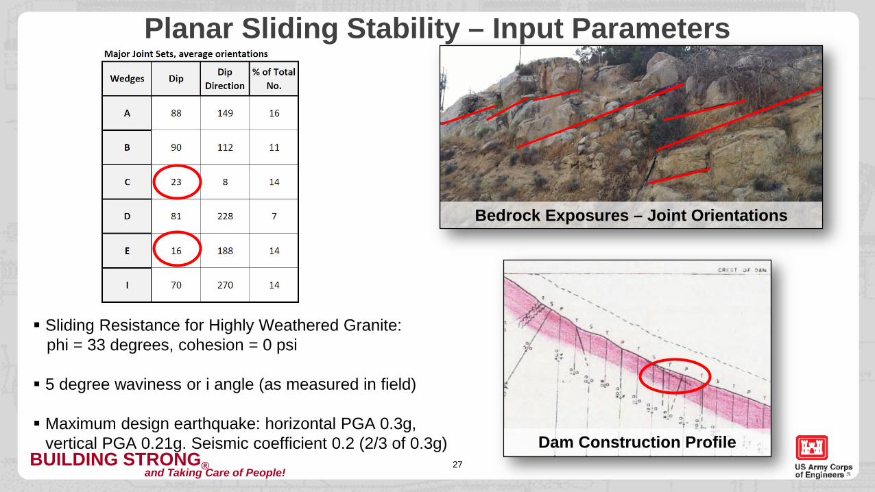
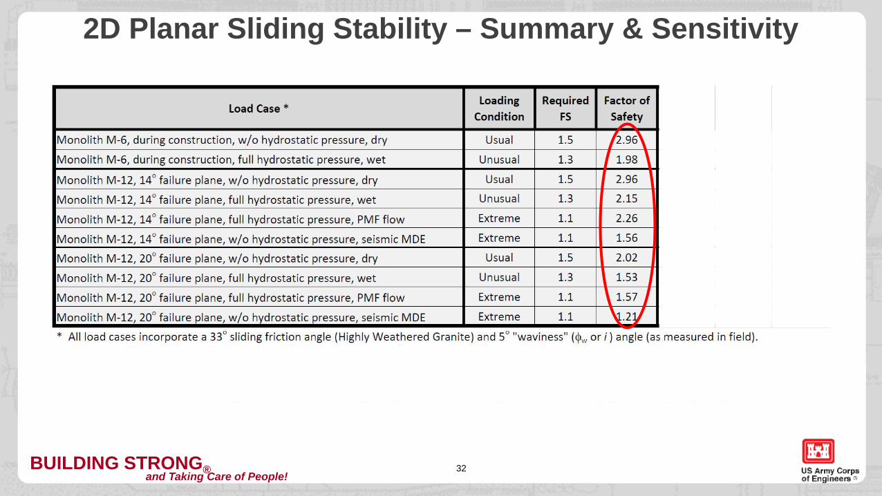
Planar Sliding Stability – Input Parameters
Sliding Resistance for Highly Weathered Granite:phi = 33 degrees, cohesion = 0 psi
5 degree waviness or i angle (as measured in field)
Maximum design earthquake: horizontal PGA 0.3g, vertical PGA 0.21g. Seismic coefficient 0.2 (2/3 of 0.3g)
Bedrock Exposures – Joint Orientations
Dam Construction Profile

BUILDING STRONG®and Taking Care of People! 28
Planar Sliding – Downstream Monolith – Load Cases2680
2660
2640
2620
2600
2580
2560
0-20-40-60-80-100 20 40 60 80 100
Uplift - Groundwater
Cross Section – Downstream of Dam – 14o Plane
Approximate Base of Near-Surface Decomposed Granite
Top of Ground
Spillway
Potential Failure Plane(47.8’ length, 14 degree inclination)
Required Factor of
SafetyDry Jointsno uplift Usual
Unusual
Extreme
Extreme
1.5
1.3
1.1
1.1
Rain - Wet Jointsfull upliftFlood PMFfull upliftEarthquake MDEno uplift
Load Case14o Plane
Loading Condition
BUILDING STRONG®and Taking Care of People! 29
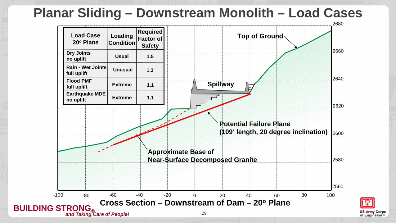
Planar Sliding – Downstream Monolith – Load Cases2680
2660
2640
2620
2600
2580
2560
0-20-40-60-80-100 20 40 60 80 100
Cross Section – Downstream of Dam – 20o Plane
Approximate Base of Near-Surface Decomposed Granite
Top of Ground
Spillway
Potential Failure Plane(109’ length, 20 degree inclination)
Load Case20o Plane
Loading Condition
Required Factor of
SafetyDry Jointsno uplift Usual
Unusual
Extreme
Extreme
1.5
1.3
1.1
1.1
Rain - Wet Jointsfull upliftFlood PMFfull upliftEarthquake MDEno uplift
BUILDING STRONG®and Taking Care of People! 30
2660
2640
2620
2600
2580
2560
0-20-40-60-80-100 20 40 60 80 100
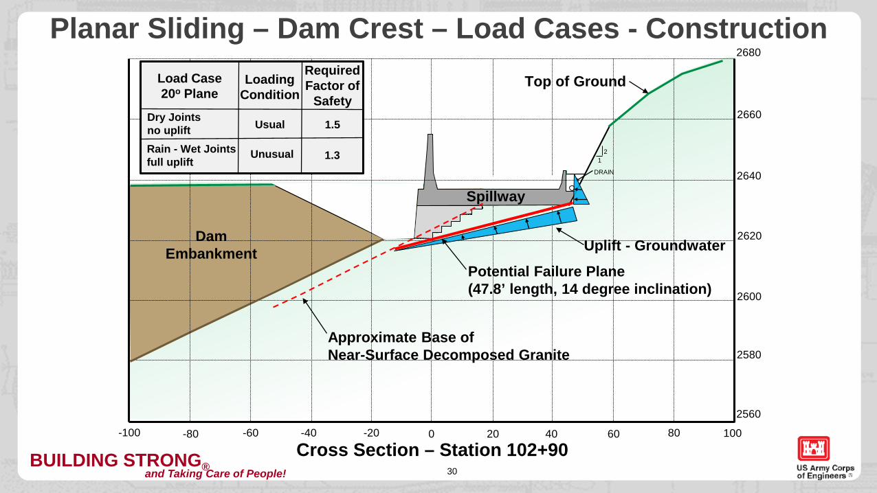
SP
21
Cross Section – Station 102+90
Approximate Base of Near-Surface Decomposed Granite
DRAIN
Top of Ground
Dam Embankment
Spillway
2680Planar Sliding – Dam Crest – Load Cases - Construction
Load Case20o Plane
Loading Condition
Required Factor of
SafetyDry Jointsno uplift Usual
Unusual
1.5
1.3Rain - Wet Jointsfull uplift
Uplift - Groundwater
Potential Failure Plane(47.8’ length, 14 degree inclination)
BUILDING STRONG®and Taking Care of People!31
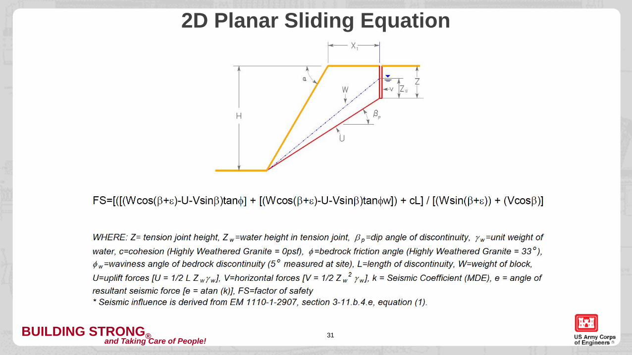
2D Planar Sliding Equation
BUILDING STRONG®and Taking Care of People!32
2D Planar Sliding Stability – Summary & Sensitivity
BUILDING STRONG®and Taking Care of People! 33
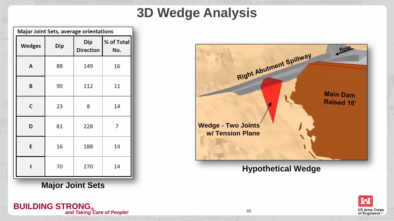
3D Wedge Analysis
Wedge - Two Joints w/ Tension Plane
Hypothetical Wedge
Major Joint Sets
BUILDING STRONG®and Taking Care of People! 34
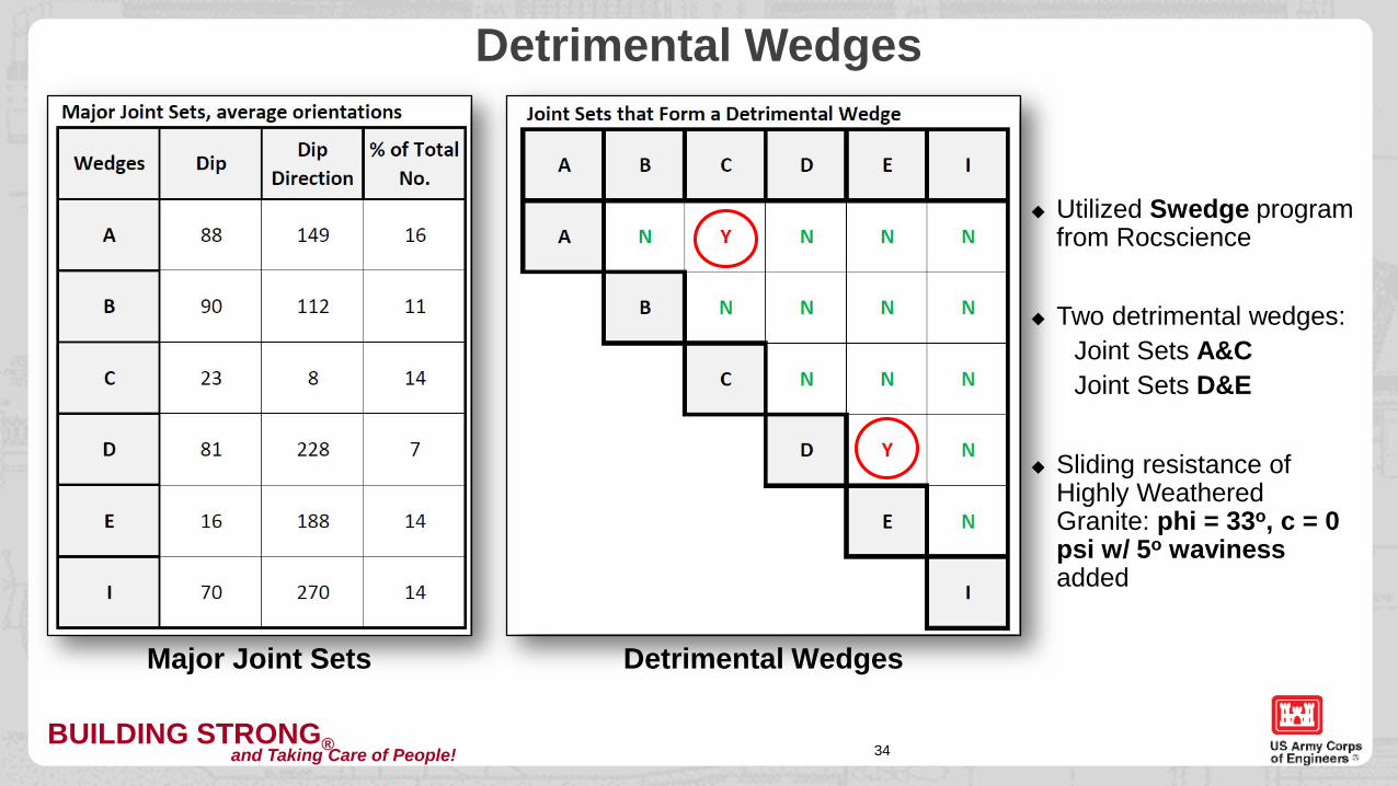
Detrimental Wedges
Major Joint Sets Detrimental Wedges
Utilized Swedge program from Rocscience
Two detrimental wedges:Joint Sets A&CJoint Sets D&E
Sliding resistance of Highly Weathered Granite: phi = 33o, c = 0 psi w/ 5o waviness added
BUILDING STRONG®and Taking Care of People!
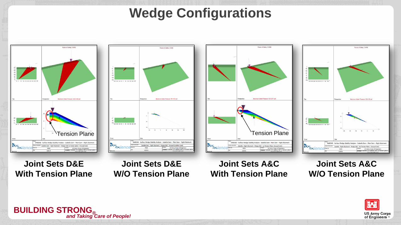
Wedge Configurations
Joint Sets D&EWith Tension Plane
Joint Sets D&EW/O Tension Plane
Joint Sets A&CWith Tension Plane
Joint Sets A&CW/O Tension Plane
Tension Plane Tension Plane
BUILDING STRONG®and Taking Care of People!
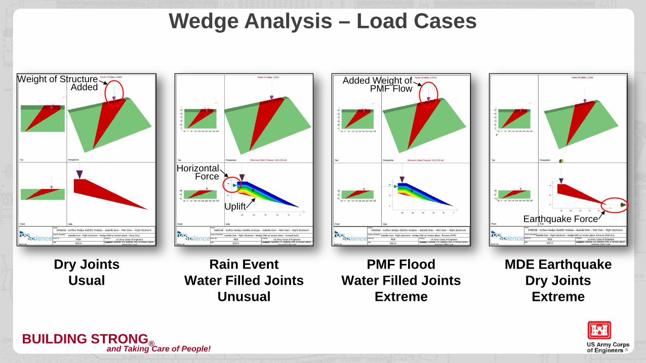
Wedge Analysis – Load Cases
Dry JointsUsual
Rain EventWater Filled Joints
Unusual
PMF FloodWater Filled Joints
Extreme
MDE EarthquakeDry JointsExtreme
Weight of StructureAdded
HorizontalForce
Uplift
Added Weight of PMF Flow
Earthquake Force
BUILDING STRONG®and Taking Care of People!37
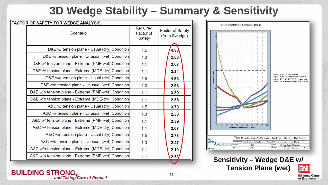
3D Wedge Stability – Summary & Sensitivity
Sensitivity – Wedge D&E w/ Tension Plane (wet)
BUILDING STRONG®and Taking Care of People!38
Stability Analysis for the Right Abutment Spillway – Isabella Dam, CAOUTLINE
A. PROJECT INFORMATION
B. SPILLWAY STABILITY
C. CUT-SLOPE STABILITY
1. Project Location2. Project Description3. Site Geology
1. Founding Elevations2. Plane Analysis3. Wedge Analysis
1. Stereonet Analysis2. Construction Concerns
BUILDING STRONG®and Taking Care of People! 39
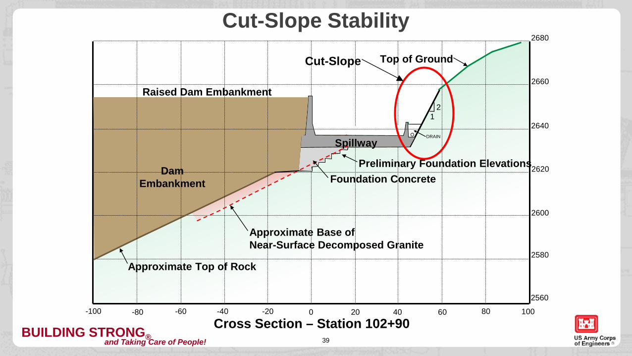
Cut-Slope Stability2680
2660
2640
2620
2600
2580
2560
0-20-40-60-80-100 20 40 60 80 100
SP
Foundation Concrete
21
Cross Section – Station 102+90
Approximate Base ofNear-Surface Decomposed Granite
DRAIN
Top of Ground
Dam Embankment
Approximate Top of Rock
Spillway
Raised Dam Embankment
Preliminary Foundation Elevations
Cut-Slope
BUILDING STRONG®and Taking Care of People!
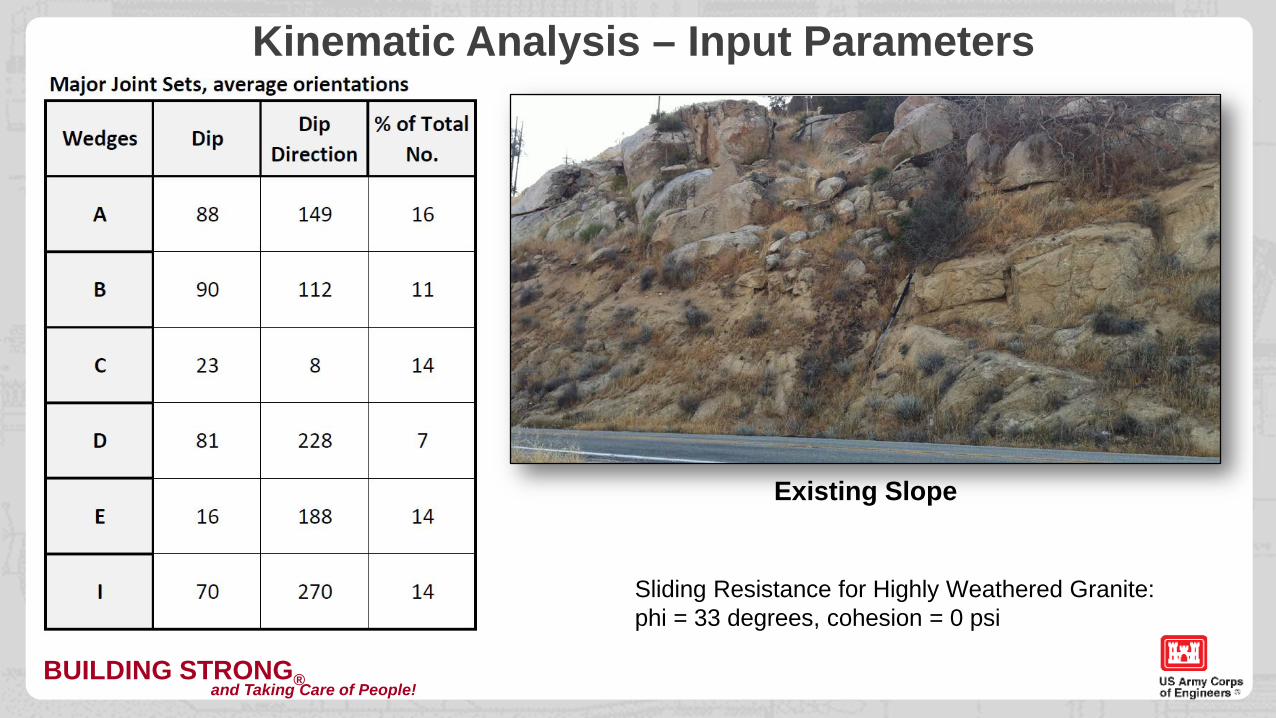
Kinematic Analysis – Input Parameters
Sliding Resistance for Highly Weathered Granite:phi = 33 degrees, cohesion = 0 psi
Existing Slope
BUILDING STRONG®and Taking Care of People!41
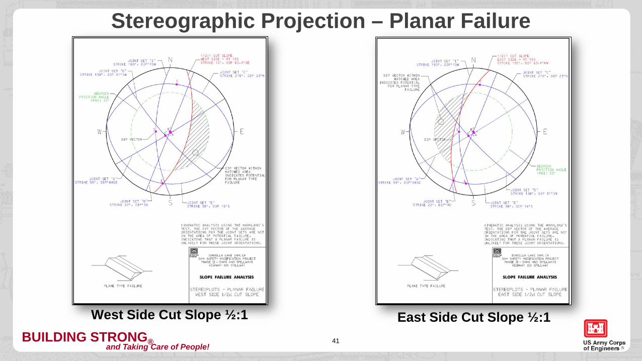
Stereographic Projection – Planar Failure
West Side Cut Slope ½:1 East Side Cut Slope ½:1
BUILDING STRONG®and Taking Care of People!42
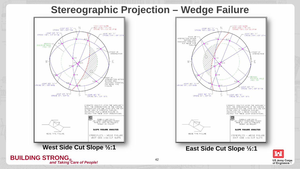
West Side Cut Slope ½:1 East Side Cut Slope ½:1
Stereographic Projection – Wedge Failure
BUILDING STRONG®and Taking Care of People!43
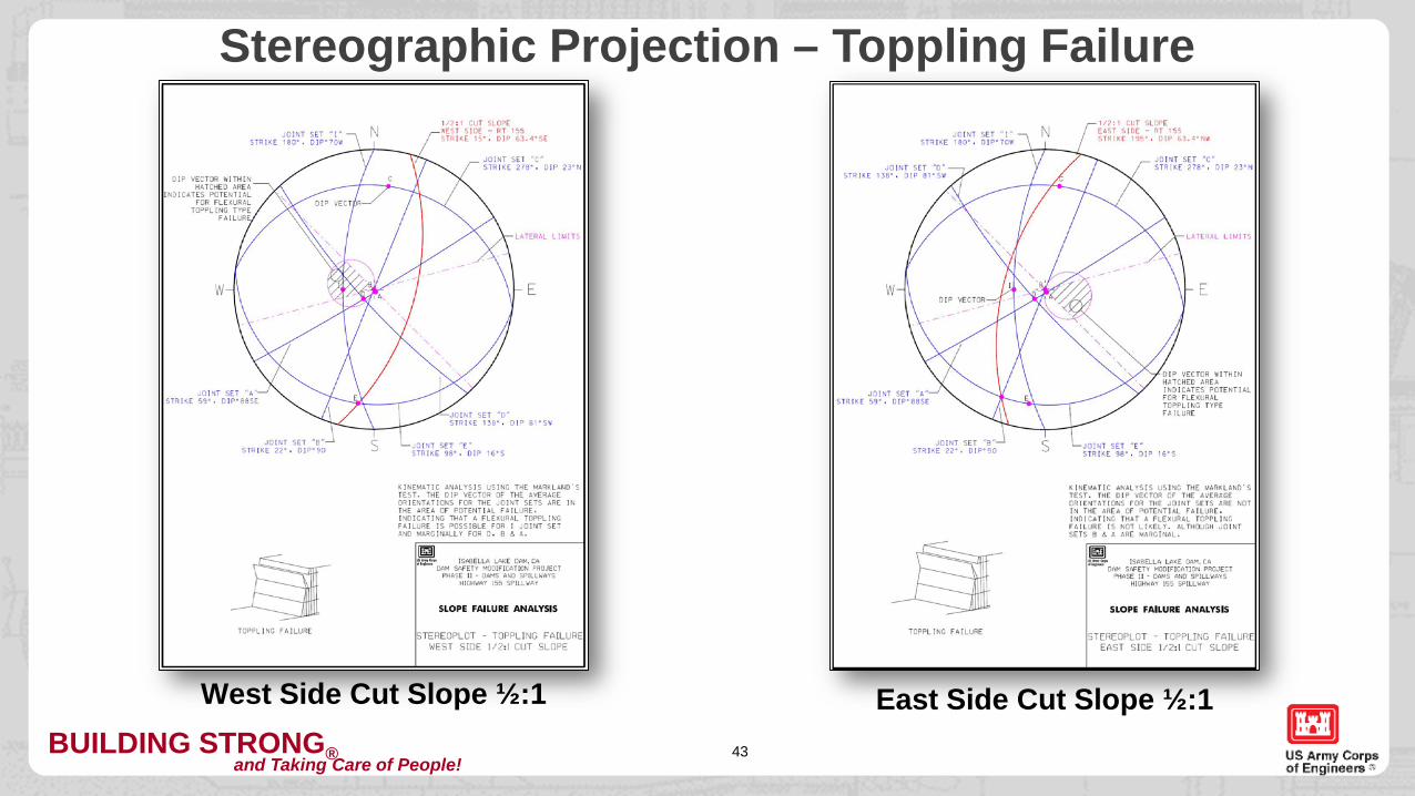
West Side Cut Slope ½:1 East Side Cut Slope ½:1
Stereographic Projection – Toppling Failure
BUILDING STRONG®and Taking Care of People!44
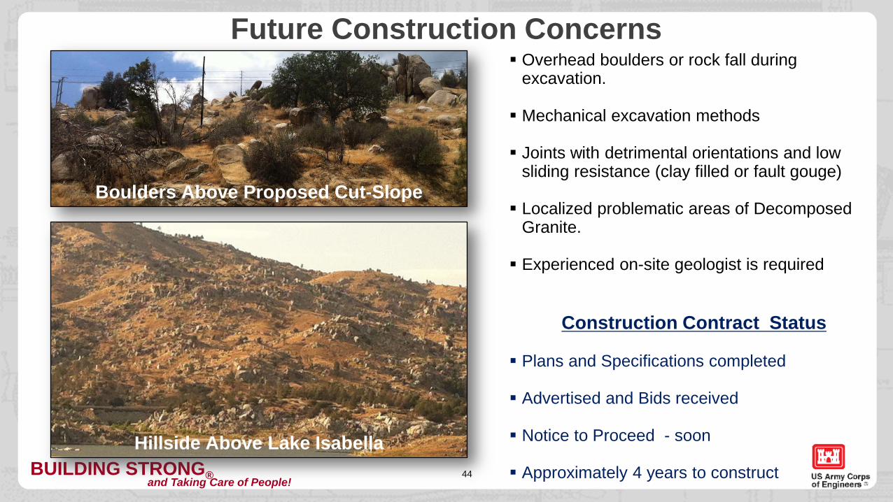
Future Construction Concerns Overhead boulders or rock fall during
excavation.
Mechanical excavation methods
Joints with detrimental orientations and low sliding resistance (clay filled or fault gouge)
Localized problematic areas of Decomposed Granite.
Experienced on-site geologist is required
Construction Contract Status
Plans and Specifications completed
Advertised and Bids received
Notice to Proceed - soon
Approximately 4 years to construct
Boulders Above Proposed Cut-Slope
Hillside Above Lake Isabella
BUILDING STRONG®and Taking Care of People!45
Stability Analysis for the Right Abutment Spillway – Isabella Dam, CACONCLUSIONS / TAKE AWAYS
1. Sliding stability for structures can be determined by utilizing equations and methods typically used for cut-slope design. (If the proposed structure is on the side of a hill)
2. Bedrock weathering can have significant impact on rock strength and influence structural design.
3. How can anyone can talk so much about such a small project?
BUILDING STRONG®and Taking Care of People!46
Stability Analysis for the Right Abutment SpillwayIsabella Dam, CA