st-264 city of durham
TRANSCRIPT


ST-264 CITY OF DURHAM
2
This page intentionally left blank
CITY OF DURHAM

ST-264 CITY OF DURHAM
3
FAYETTEVILLE ROAD IMPROVEMENTS
PUBLIC WORKS
CONTRACT PROPOSAL
CONTRACT NUMBER: ST-264
COUNTY: DURHAM
DESCRIPTION:
DATE OF ADVERTISEMENT: 6/22/2018
MANDATORY PRE-BID MEETING: 7/11/2018 3:00 PM,
Durham City Hall Conference Room GB (Ground
Floor Planning Area)
BID OPENING: 7/24/2018 3:00 PM
*** NOTICE ***
ALL BIDDERS SHALL COMPLY WITH ALL APPLICABLE LAWS REGULATING THE PRACTICE OF
GENERAL CONTRACTING AS CONTAINED IN CHAPTER 87 OF THE GENERAL STATUTES OF
NORTH CAROLINA. FOR CONTRACTS $30,000 OR MORE, EXCEPT FOR CERTAIN SPECIALTY
WORK AS DETERMINED BY THE LICENSING BOARD, BIDDERS ARE REQUIRESD TO BECOME
LICENSED BY THE NC LICENSING BOARD. NON-LICENSED BIDDERS ARE PERMITED 60 DAYS
AFTER BID OPENING TO OBTAIN PROPER LICENSING FOR THE TYPE OF PROJECT BEING LET.
BIDDERS SHALL ALSO COMPLY WITH ALL OTHER APPLICABLE LAWS REGULATING THE
PRACTICES OF ELECTRICAL, PLUMBING, HEATING AND AIR CONDITIONING AND
REFRIGERATION CONTRACTING AS CONTAINED IN CHAPTER 87 OF THE GENERAL STATUTES
OF NORTH CAROLINA.
____________________________________________________________________________
NAME OF BIDDER
____________________________________________________________________________
ADDRESS OF BIDDER
RETURN BIDS TO: City of Durham Public Works Department
Attention: Charles Rice
Person’s Title: Project Manager
Physical Address: 101 City Hall Plaza
Suite 3100
Durham, NC 27701
ALL BIDS MUST BE RECEIVED PRIOR TO THE DATE AND TIME LISTED ABOVE.

ST-264 CITY OF DURHAM
4
INVITATION TO BID
Contract: ST-264
Project: Fayetteville Road Improvements
Owner: City of Durham
101 City Hall Plaza
Suite 3100
Durham, North Carolina 27701
Issuing Office: Public Works Department
Attention: Charles J. Rice, EI
City of Durham
Public Works Department
Engineering Division
101 City Hall Plaza
Durham, North Carolina 27701
(919) 560-4326 ext. 30266
Date: 6/22/2018
The City of Durham will open sealed formal Bids submitted by prequalified Bidders at 3:00
P.M. on Tuesday July 24, 2018 for Contract ST-264, ‘Fayetteville Road Improvements’, in
Conference Room 3A, 101 City Hall Plaza, Durham, North Carolina. The Project involves the
furnishing of all materials, labor, equipment, tools, et cetera, unless otherwise specified, for the
roadway widening project.
The Project Manual and Plans may be viewed and downloaded, free of charge, from the City of
Durham, Public Works Division web site:
http://durhamnc.gov/2877/ST-264-Fayetteville-Road-Improvements
Bidders are encouraged to forward any questions to the Project Manager.
The City Council of the City of Durham reserves the right to reject any or all of the Bids. All
Bids must include a non-collusion affidavit.
To ensure that all Bidders using the Purchasing Division’s web site are kept up to date on any
Addenda, changes, or information notices, please send an e-mail to [email protected]
indicating your intention to prepare a Bid for the Project. Failure to complete this step may
render your Bid as non- responsive.
Each Bidder is advised that the Work may be inspected and supervised by an Engineer of or firm
under the direction of the City of Durham. The Engineer or firm may also be involved in the
identification of specific repair areas and the proposed method of repairs for the Site Work.
The City of Durham requires the Project to be completed in 90 calendar days from date of Notice
to Proceed for Construction.

ST-264 CITY OF DURHAM
5
No Bid shall be considered or accepted unless at the time of its filing the same shall be
accompanied by a deposit of cash or a certified or cashier's check drawn on a bank or trust
company insured by the Federal Deposit Insurance Corporation (FDIC), in an amount equal to
five percent (5%) of the amount of the Bid. The check shall be made payable to the City of
Durham. Said deposit shall guarantee that the Contract will be entered into by the successful
Bidder if the award is made. Such deposit of cash or certified or cashier's check may be held by
the City until the successful Bidder has executed and delivered the Contract Documents,
including performance and payment bond.
In lieu of the cash deposit or certified or cashier’s check mentioned above, the Bidder may file a
Bid bond in the same amount executed by a corporate surety authorized to execute such bonds in
North Carolina and in the form attached to the Bidding Documents or on file with the Engineer.
Bid bond forms enclosed as part of the Bidding.
Documents must be properly executed at the time Bids are submitted before Bid will be
considered. Properly executed Power of Attorney of the corporate surety's agent shall accompany
such bond and be attached to the page provided therefore in the Bidding Documents.
Bids shall be submitted under a condition of irrevocability, except as required by law, for a
period of ninety (90) days after Bid opening.
The City of Durham reserves the right to accept or reject any or all Bids.

ST-264 CITY OF DURHAM
6
INSTRUCTIONS TO BIDDERS
PLEASE READ ALL INSTRUCTIONS CAREFULLY BEFORE PREPARING AND
SUBMITTING YOUR BID.
All bids shall be prepared and submitted in accordance with the following requirements.
Failure to comply with any requirement shall cause the bid to be considered irregular and
shall be grounds for rejection of the bid.
1. The bid form furnished by CITY OF DURHAM with the proposal shall be used and shall not
be altered in any manner. DO NOT SEPARATE THE BID FORM FROM THE
PROPOSAL!
2. All entries on the bid form, including signatures, shall be written in ink.
3. The Bidder shall submit a unit price for every item on the bid form. The unit prices for the
various contract items shall be written in figures. ***Unit prices must be limited to TWO
decimal places.***
4. An amount bid shall be entered on the bid form for every item. The amount bid for each item
shall be determined by multiplying each unit bid by the quantity for that item, and shall be
written in figures in the "Amount Bid" column of the form.
5. The total amount bid shall be written in figures in the proper place on the bid form. The total
amount shall be determined by adding the amounts bid for each item.
6. Changes in any entry shall be made by marking through the entry in ink and making the
correct entry adjacent thereto in ink. A representative of the Bidder shall initial the change in ink.
Do not use “White Out” or similar product to make corrections.
7. The bid shall be properly executed. All bids shall show the following information:
a. Name of individual, firm, corporation, partnership, or joint venture submitting bid.
b. Name of individual or representative submitting bid and position or title.
c. Name, signature, and position or title of witness.
d. Federal Identification Number
e. Contractor's License Number (If available)
8. Bids submitted by corporations shall bear the seal of the corporation.
9. The bid shall not contain any unauthorized additions, deletions, or conditional bids.
10. The bidder shall not add any provision reserving the right to accept or reject an award, or to
enter into a contract pursuant to an award.
11. THE PROPOSAL WITH THE BID FORM STILL ATTACHED SHALL BE
PLACED IN A SEALED ENVELOPE AND SHALL HAVE BEEN DELIVERED TO AND

ST-264 CITY OF DURHAM
7
RECEIVED IN THE (CITY OF DURHAM PUBLIC WORKS DEPARTMENT, 101 CITY
HALL PLAZA, SUITE 3100, DURHAM NC 27701), BY (3:00 PM) ON, TUESDAY, JULY
10, 2018.
12. The sealed bid must display the following statement on the front of the sealed envelope:
“QUOTATION FOR ST-264,’ FAYETTEVILLE ROAD IMPROVEMENTS’. TO BE
OPENED AT BY (3:00 PM) ON, TUESDAY, JULY 24, 2018.
13. If delivered by mail, the sealed envelope shall be placed in another sealed envelope and the
outer envelope shall be addressed as follows:
14. State Treasurer’s lists regarding Iran and Boycott of Israel. If the candidate or the City
signs the contract on October 1, 2017 or afterwards, and the value of the contract is $1,000 or
more, the following applies unless the candidate otherwise states in its proposal: the candidate
affirms (by submitting a proposal) that (1) its name does not appear on the list of companies that
are engaged in a boycott of Israel developed by the N. C. State Treasurer under N.C.G.S.
147-86.81(a)(1) or on a list created by the Treasurer pursuant to N.C.G.S. 147-86.58 as a
company engaging in investment activities in Iran, and (2) it has no reason to expect that its
name will appear on either of those lists. Take notice that a contract between a company named
on either list and the City may be void.
CITY OF DURHAM PUBLIC WORKS DEPARTMENT
Attn: CHARLES RICE
101 CITY HALL PLAZA
SUITE 3100
DURHAM, NC 27701

ST-264 CITY OF DURHAM
8
TABLE OF CONTENTS CONTRACT PROPOSAL ......................................................................................................................... 3 INVITATION TO BID ............................................................................................................................... 4 INSTRUCTIONS TO BIDDERS ............................................................................................................... 6 TABLE OF CONTENTS............................................................................................................................ 8 NCDOT STANDARD NOTES ................................................................................................................ 10 CITY OF DURHAM CONTRACT FORMS ........................................................................................... 12 GENERAL PROVISIONS ....................................................................................................................... 21
CONTRACT TIME AND LIQUIDATED DAMAGES ...................................................................... 22
NO MAJOR CONTRACT ITEMS: ...................................................................................................... 22
NO SPECIALTY ITEMS: ..................................................................................................................... 22
FUEL AND ASPHALT PRICE ADJUSTMENTS: ............................................................................. 22
INTERMEDIATE CONTRACT TIME NUMBER 1 AND LIQUIDATED DAMAGES: .................. 23
INTERMEDIATE CONTRACT TIME NUMBER 2 AND LIQUIDATED DAMAGES: .................. 24
INTERMEDIATE CONTRACT TIME NUMBER 03 AND LIQUIDATED DAMAGES: ................ 24
INTERMEDIATE CONTRACT TIME NUMBER 04 AND LIQUIDATED DAMAGES: ................ 24
UTILITY COORDINATION: .............................................................................................................. 25
PERMANENT VEGETATION ESTABLISHMENT: ......................................................................... 26
PORTABLE CONCRETE BARRIER - (Partial Payments for Materials): .......................................... 26
MAINTENANCE OF THE PROJECT: ............................................................................................... 26
EROSION AND SEDIMENT CONTROL/STORMWATER CERTIFICATION: ............................. 27
DISADVANTAGED BUSINESS ENTERPRISE (LOCAL GOVERNMENT AGENCIES) ............. 32
U.S. DEPARTMENT OF TRANSPORTATION HOTLINE: ............................................................. 32
PROCEDURE FOR MONITORING BORROW PIT DISCHARGE: ................................................. 32
ASPHALT BINDER CONTENT OF ASPHALT PLANT MIXES: .................................................... 34
ROADWAY PROVISIONS ................................................................................................................. 35
CONSTRUCTION SEQUENCE: ......................................................................................................... 35
CLEARING AND GRUBBING - METHOD II: .................................................................................. 35
BURNING RESTRICTIONS: .............................................................................................................. 35
BORROW EXCAVATION (In Place or Truck Measurement):........................................................... 35
FLOWABLE FILL: .............................................................................................................................. 35
AUTOMATED FINE GRADING: ....................................................................................................... 36
INCIDENTAL STONE BASE: ............................................................................................................ 36
ASPHALT CONCRETE PLANT MIX PAVEMENTS: ...................................................................... 37
PRICE ADJUSTMENT - ASPHALT BINDER FOR PLANT MIX: .................................................. 39
PATCHING EXISTING PAVEMENT: ............................................................................................... 39
HIGH STRENGTH CONCRETE FOR DRIVEWAYS: ...................................................................... 40
TEMPORARY TRAFFIC CONTROL DEVICES: .............................................................................. 40
PERMANENT SEEDING AND MULCHING: ................................................................................... 41

ST-264 CITY OF DURHAM
9
Stabilization Requirements: .................................................................................................................. 41
SEEDING AND MULCHING: ............................................................................................................ 42
WATTLE: ............................................................................................................................................. 44
WATTLES with Polyacrylamide (PAM): ............................................................................................ 45
REMOVAL AND REPLACEMENT OF STREET SIGNS AND MAILBOXES: .............................. 47
PERMITS.............................................................................................................................................. 48
STANDARD SPECIAL PROVISIONS ............................................................................................... 55
UNDERGROUND DETENTION CONTROL STRUCTURE 5A ...................................................... 55
UNDERGROUND DETENTION CONTROL STRUCTURE 6A ...................................................... 55
BOLLARDS (HINGED AND UNHINGED) ....................................................................................... 55
TEMPORARY CONSTRUCTION ENTRANCE ................................................................................ 55
RETAINING WALL (MODULAR BLOCK WALL) ......................................................................... 55
REINFORCED BACKFILL PLACEMENT ........................................................................................ 62
CAP INSTALLATION ......................................................................................................................... 62
AS-BUILT CONSTRUCTION TOLERANCES.................................................................................. 62
FIELD QUALITY CONTROL AND ASSURANCE .......................................................................... 63
TRAIL SIGN RESET: .......................................................................................................................... 63
SOLITE PARK SIGN, RELOCATE .................................................................................................... 64
METAL FENCE RESET: ..................................................................................................................... 64
BOLLARD RESET: ............................................................................................................................. 64
NCDOT GENERAL SEED SPECIFICATION FOR SEED QUALITY ............................................. 65
ADJUSTMENT OF MANHOLES: ...................................................................................................... 68
ERRATA .............................................................................................................................................. 68
PLANT AND PEST QUARANTINES ................................................................................................ 69
Traffic Signals:………………………………………………..TS-1 THROUGH TS-83 .................... 69
E-VERIFY AFFIDAVIT: ..................................................................................................................... 70
IRAN DIVESTMENT ACT: ................................................................................................................ 71
TWELVE MONTH GUARANTEE – LGA Projects ........................................................................... 71 EXECUTION OF BID.............................................................................................................................. 72
ITEM SHEETS bUXTON rIDDLE ROAD ......................................................................................... 80 ITEM SHEETS fAYETTEVILLE ROAD ............................................................................................... 86

ST-264 CITY OF DURHAM
10
NCDOT STANDARD NOTES
A. NCDOT Standard Specifications – The 2018 North Carolina Department of
Transportation Standard Specifications for Roads and Structures, herein referred to as the
‘Standard Specifications’, and the 2018 Roadway Standard Drawings, shall apply to all
portions of this project except as may be modified by this document.
B. Bidder Prequalification - Bidders are required to be prequalified with NCDOT for their
specific discipline. Contractors wishing to become prequalified may obtain information
through the NCDOT website at:
https://connect.ncdot.gov/business/Pages/default.aspx
C. Small Disadvantaged Business Enterprise References - Since this is a City of Durham
project with SDBE participation, only those requirements and goals set forth by the City
are applicable.
D. Award of Contract - The contract will be awarded to the lowest responsible, responsive
bidder. Alternate items will not be considered in determining the low bidder and will only
be evaluated after the award of the contract is made.
E. Contractor Licensing – Bidders are permitted 60 days, after bid opening, to become
licensed by the North Carolina Licensing Board. If they fail to do so within 60 days, their
bid will be considered non-responsive and will be rejected. If the successful bidder does
not hold the proper license to perform any plumbing, heating, air conditioning, or electrical
work in this contract, he will be required to sublet such work to a contractor properly
licensed in accordance with Article 2 of Chapter 87 of the General Statutes (licensing of
heating, plumbing, and air conditioning contractors) and Article 4 of Chapter 87 of the
General Statutes (licensing of electrical contractors).
F. Bonds - Please note that all Bid Bonds, Payment Bonds, and Performance Bonds required
for this project, shall be City of Durham bonds:
Bid Bonds see Appendix E
Payment Bonds see Appendix G
Performance Bonds see Appendix G
G. Liability Insurance – In addition to any insurance requirements as may be required by the
City, the Contractor is obligated to comply with Article 107-15 of the Standard
Specifications including the dollar limits set forth.
H. Buy America – This project shall be governed by the Buy America requirements, for the
use of domestic steel and iron products, as outlined in the Standard Specifications and
Special Provision SP1 G120.
I. Proprietary Items - When a proprietary (brand name) product, whether material, equipment
or procedure, are specified in the plans or specifications, they are used only to denote the
style, type, character, and quality desired of the product. They do not restrict the bidder
from proposing other brands, makes, or manufacturers, which are determined to be of equal
quality. The approval, or disapproval of those products, will be made by the Engineer prior
to allowing those product(s) or material(s) to be incorporated into the work.

ST-264 CITY OF DURHAM
11
J. Retainage by LGAs – The City will not retain any amount or percentage from progress
payments or final estimates due the contractor.
Retainage by Contractors – Contractors are NOT permitted to retain any amount or
percentage from monies due their subcontractors or material suppliers on federally funded
projects except as permitted by Subarticle 109-4(B) of the Standard Specifications.
K. Traffic Control –The requirements of the Manual on Uniform Traffic Control Devices
(MUTCD) – FHWA, as amended by the NCDOT Supplement to MUTCD, shall apply.
Traffic Control, both vehicular and pedestrian, shall be maintained throughout the project
as required by these specifications as modified by the project plans or special provisions.

ST-264 CITY OF DURHAM
12
CITY OF DURHAM CONTRACT FORMS
The successful bidder to whom the contract is awarded (i.e., “Contractor”) shall execute
the following Standard City of Durham Contract Form for NCDOT Construction Projects with the
City of Durham evidencing its agreement to the terms and conditions of this Contract Proposal.

ST-264 CITY OF DURHAM
13
STANDARD CITY OF DURHAM CONTRACT FORM
FOR NCDOT CONSTRUCTION PROJECTS
THIS CONTRACT is dated, made and entered into as of the _______ day of
________________, 20______, by and between the City of Durham (“City”), a N. C. municipal
corporation, and [name of firm] (“Contractor”), [indicate type of legal entity, for instance:
a corporation organized and existing under the laws of [name of State];
a limited liability company organized and existing under the laws of [name of State];
a professional corporation organized and existing under the laws of [name of State];
a professional association organized and existing under the laws of [name of State];
a limited partnership organized and existing under the laws of [name of State];
a sole proprietorship;
or a general partnership
If it’s a corporation, LLC, or limited partnership, use the above “organized and existing”
language, and do not substitute news about the contractor’s principal office or place of
business.]
The City of Durham and Contractor, in consideration of the mutual covenants set forth
herein, agree as follows:
1. Background and Incorporation of Contract Proposal. The City has accepted the
proposal of the Contractor for construction of the project advertised by the City on the _____ day
of ________________, 20_____ in the Contract Proposal titled “Fayetteville Road
Improvements”, Project No. ST-264(hereinafter, “Contract Proposal” including Addenda). The
terms and conditions of the Contract Proposal are incorporated herein by reference and made a
part of this Contract.
2. Description of Work. Obligations of Contractor. (a) The Contractor, at his (its) own
proper cost and expense and with skill and diligence, shall complete all Work, including
furnishing all labor, tools, materials, and equipment, and do all things necessary for the proper
construction and completion of the Work pursuant to the terms, and consistent with the plans,
specifications, drawings, schedules, and other documents contained or incorporated by reference,
in the Contract Proposal.
(b) The Contractor shall further perform the Work in accordance with the directions (not
inconsistent therewith) given from time to time by the City individual assigned to administer this
Contract, referred to as the Project Manager or Engineer, or other person as the City Manager
may designate. For purposes of this Contract, the term “Engineer” shall refer to the City
Manager of the City of Durham or his or her designee acting directly or through a duly
authorized representative, including the Project Manager or a designated engineering consultant,
acting within the scope of particular assigned or contracted duties and authority.
(c) The Contractor agrees to receive the prices stated in Exhibit A, the “Itemized
Proposal Form,” in full compensation for furnishing materials, and for labor in moving materials
and executing all the Work contemplated and shall be responsible for all loss or damage arising
out of the nature of the Work aforesaid or from any action of the elements or from any
unforeseen obstruction or difficulties which may be encountered in the prosecution and delivery

ST-264 CITY OF DURHAM
14
of the same, and for all risks of every nature and description connected with the Work and
furnishing the materials until their final completion and acceptance; also, for expense incurred by
or in consequence of the suspense; also, for expense incurred by or in consequence of the
suspense or of the discontinuance of said work and furnishing said materials according to the
Contract Proposal and requirements of the Engineer under them.
3. Quality and Workmanship. All Work under this Contract shall be performed and
completed to the satisfaction of the Project Manager and Engineer and the Project Manager and
Engineer shall in all cases of dispute determine the quantity, quality, acceptability and fitness of
the work and materials and of several portions thereof which are to be paid for under this
Contract and shall decide and determine all questions which may arise as to the measurements,
lines, levels and dimensions of the work and all questions respecting the true construction,
interpretation, or meaning of the plans and specifications. In case of dispute between the
Contractor and the Project Manager and Engineer, the decision and determination of the latter
shall be taken and shall be final and conclusive.
4. Compensation. The total dollar amount to be paid under this Contract by the City to
the Contractor shall not exceed $_______________, the Itemized Proposal From, as provided in
Exhibit A. The City will make partial payments based on the progress of the work and payment
requests submitted by the Contractor. Payment will be made within twenty-five (25) days after
receipt of a correct payment request.
On the completion of the Work, the Contractor shall proceed with due diligence to
measure up the work and material and present his final estimate to the City, whereupon the City
shall pay within forty-five (45) days thereafter such amount, less payments previously made, and
payments of such final amount shall release the City from claims for work done or materials
furnished under this Contract.
The City will require release of all claims for materials or labor furnished for this work
prior to the payment of the final estimate. The Contractor shall furnish the City with a written
statement sworn before a Notary Public to the effect that all payments have been made for labor
and materials used in this construction and that claims, suits, and proceedings of every name and
description against the City, its officers and agents, have been settled.
It is further mutually agreed between the parties that no estimate or partial payment made
under this Contract shall be conclusive evidence of the performance of this Contract, either
wholly or in part, and that no such payment shall be construed to be an acceptance of defective
work or improper materials.
5. Prompt Payment to Subcontractors. Pursuant to NC General Statute 143-134.1(b6),
the prompt payment provisions of Section 109-4(B) of the 2018 North Carolina Department of
Transportation Standard Specifications for Roads and Structures (hereinafter, “Standard
Specifications”) and other prompt payment provisions of this Contract shall preempt the
provisions of NC General Statute 143-134.1 (b1), (b2), (b3) and (b4) to the extent of any
conflict.
6. City Changes to NCDOT Standard Specifications. The Contract Proposal makes
certain changes to the Standard Specifications. This Contract makes the following additional

ST-264 CITY OF DURHAM
15
changes to the Standard Specifications:
(a) Section 101-3:
(i) Delete the definition of “Engineer” on page 1-5 and replace with the following
definition: “The City Manager of the City of Durham or his or her designee
acting directly or through a duly authorized representative, including the Project
Manager or a designated engineering consultant, acting within the scope of
particular assigned or contracted duties and authority.”
(ii) In the definition for “Final Estimate”, delete the last sentence referencing the
verified claim procedure in lines 5 and 6 on page 1-6.
(iii) The definition of “Department” shall include the City of Durham in reference to
the administration of this contract.
(b) Sections 102-2 and 102-15 – The term “Engineer” in these sections shall refer to the
State Highway Administrator of the North Carolina Department of Transportation,
acting directly or through a duly authorized representative, such representative
acting within the scope of particular assigned duties or authority.
(c) Section 103-3 - Criteria for Withdrawal of Bid – Delete subsections (A), (B), (C) and
(D) in their entirety and replace with the following statement:
A bidder submitting a bid pursuant to NC General Statute 143-129 may
withdraw its bid in accordance with the terms of NC General Statute 143-129.1.
(d) Section 107-24 – Delete this section in its entirety.
6. Indemnification. Notwithstanding any indemnification requirements contained in the
Standard Specifications, the Contractor shall also agree to the following indemnification
provision as applied to the City of Durham:
(a) To the maximum extent allowed by law, the Contractor shall defend, indemnify, and
save harmless Indemnitees from and against all Charges that arise in any manner from, in
connection with, or out of this contract as a result of acts or omissions of the Contractor or
subcontractors or anyone directly or indirectly employed by any of them or anyone for whose
acts any of them may be liable. In performing its duties under this subsection “a,” the Contractor
shall at its sole expense defend Indemnitees with legal counsel reasonably acceptable to City.
(b) Definitions. As used in subsections “a” above and “c” below -- “Charges” means
claims, judgments, costs, damages, losses, demands, liabilities, duties, obligations, fines,
penalties, royalties, settlements, and expenses (included without limitation within “Charges” are
(1) interest and reasonable attorneys' fees assessed as part of any such item, and (2) amounts for
alleged violations of sedimentation pollution, erosion control, pollution, or other environmental
laws, regulations, ordinances, rules, or orders -- including but not limited to any such alleged
violation that arises out of the handling, transportation, deposit, or delivery of the items that are
the subject of this contract). “Indemnitees” means City and its officers, officials, independent
contractors, agents, and employees, excluding the Contractor.
(c) Other Provisions Separate. Nothing in this section shall affect any warranties in
favor of the City that are otherwise provided in or arise out of this contract. This section is in
addition to and shall be construed separately from any other indemnification provisions that may
be in this contract.
(d) Survival. This section shall remain in force despite termination of this contract
(whether by expiration of the term or otherwise) and termination of the services of the Contractor

ST-264 CITY OF DURHAM
16
under this contract.
(e) Limitations of the Contractor's Obligation. If this section is in, or is in connection
with, a contract relative to the design, planning, construction, alteration, repair or maintenance of
a building, structure, highway, road, appurtenance or appliance, including moving, demolition
and excavating connected therewith, then subsection “a” above shall not require the Contractor
to indemnify or hold harmless Indemnitees against liability for damages arising out of bodily
injury to persons or damage to property proximately caused by or resulting from the negligence,
in whole or in part, of Indemnitees.
7. Liability Insurance. The Contractor shall maintain the more stringent minimum
liability insurance coverage between that required by the NCDOT and the following City
required minimum coverage to be accompanied by a certificate of liability insurance:
Commercial General Liability — Combined single limit of no less than $1,000,000 each
occurrence and $2,000,000 aggregate. Coverage shall not contain any endorsement(s) excluding
nor limiting Product/Completed Operations, Contractual Liability or Cross Liability.
Automobile Liability — Limits of no less than $1,000,000 Combined Single Limit. Coverage
shall include liability for Owned, Non-Owned and Hired automobiles. In the event Contractor
does not own automobiles, Contractor agrees to maintain coverage for Hired and Non-Owned
Auto Liability, which may be satisfied by way of endorsement to the Commercial General
Liability policy or separate Auto Liability policy. Automobile coverage is only necessary if
vehicles are used in the provision of services under this Contract and/or are brought on a City of
Durham site.
Worker’s Compensation & Employers Liability — Contractor agrees to maintain Worker’s
Compensation Insurance in accordance with North Carolina General Statute Chapter 97 and with
Employer Liability limits of no less than $1,000,000 each accident, each employee and policy
limit. This policy must include a Waiver of Subrogation.
Additional Insured — Commercial General Liability. The Additional Insured shall read ‘City
of Durham and the State of North Carolina as its interest may appear’.
Certificate of Insurance — Contractor agrees to provide City of Durham a Certificate of
Insurance evidencing that all coverage’s, limits and endorsements required herein are maintained
and in frill force and effect, and Certificates of Insurance shall provide a minimum thirty (30)
day endeavor to notify, when available, by Contractor’s insurer. If Contractor receives a non-
renewal or cancellation notice from an insurance carrier affording coverage required herein, or
receives notice that coverage no longer complies with the insurance requirements herein,
Contractor agrees to notify the City within five (5) business days with a copy of the non-renewal
or cancellation notice, or written specifics as to which coverage is no longer in compliance. The
Certificate Holder address should read:

ST-264 CITY OF DURHAM
17
City of Durham
Department of Public Works
ATTN: Charles Rice
101 City Hall Plaza
Durham, NC 27701
Umbrella or Excess Liability — Contractor may satisfy the minimum liability limits required
above under an Umbrella or Excess Liability policy. There is no minimum Per Occurrence limit
of liability under the Umbrella or Excess Liability, however, the Annual Aggregate limits shall
not be less than the highest ‘Each Occurrence’ limit for required policies. Contractor agrees to
endorse City of Durham as an ‘Additional Insured’ on the Umbrella or Excess Liability, unless
the Certificate of Insurance states the Umbrella or Excess Liability provides coverage on a
‘Follow-Form’ basis.
All insurance companies must be authorized to do business in North Carolina and be acceptable
to the City of Durham’s Risk Manager.
8. Notice. (a) This subsection (a) pertains to all notices related to or asserting default,
breach of contract, claim for damages, suspension or termination of performance, suspension or
termination of contract, and extension or renewal of the term. All such notices shall be given by
personal delivery, fax, UPS, Federal Express, a designated delivery service authorized pursuant
to 26 U.S.C. 7502(f)(2), or certified United States mail, return receipt requested, addressed as
follows. The parties are requested to send a copy by email.
To the City:
City of Durham
Department of Public Works
ATTN: Charles Rice
101 City Hall Plaza
Durham, NC 27701-3329
Fax: (919)560-4316
Email: [email protected]
To the Contractor:
[Insert name and address]
The fax number is ___________.
Email:
(b) Change of Address. Date Notice Deemed Given. A change of address, email
address, fax number, or person to receive notices under subsection (a) shall be made by notice
given pursuant to subsection (a). All notices and other communications related to or under this
contract shall be deemed given and sent at the time of actual delivery, if personally delivered or
sent by fax, personal delivery, UPS, Federal Express, or a designated delivery service. If the
notice or other communication is sent by United States mail, it shall be deemed given upon the
third calendar day following the day on which such notice or other communication is deposited
with the United States Postal Service or upon actual delivery, whichever first occurs.
9. State Law Provisions. (a) E-Verify Requirements. (A) If this contract is awarded

ST-264 CITY OF DURHAM
18
pursuant to North Carolina General Statutes (NCGS) 143-129 – (i) the contractor represents and
covenants that the contractor and its subcontractors comply with the requirements of Article 2 of
Chapter 64 of the NCGS; (ii) the words "contractor," "contractor’s subcontractors," and
"comply" as used in this subsection (A) shall have the meanings intended by NCGS 143-129(j);
and (iii) the City is relying on this subsection (A) in entering into this contract. (B) If this
contract is subject to NCGS 143-133.3, the contractor and its subcontractors shall comply with
the requirements of Article 2 of Chapter 64 of the NCGS.
(b) Iran Divestment Act Certification. The Contractor certifies that, if it submitted a
successful bid for this contract, then as of the date it submitted the bid, the Contractor was not
identified on the Iran List. If it did not submit a bid for this contract, the Contractor certifies that
as of the date that this contract is entered into, the Contractor is not identified on the Iran List. It
is a material breach of contract for the Contractor to be identified on the Iran List during the term
of this contract or to utilize on this contract any subcontractor that is identified on the Iran List.
In this Iran Divestment Act Certification section -- “Contractor” means the person entering into
this contract with the City of Durham; and “Iran List” means the Final Divestment List – Iran,
the Parent and Subsidiary Guidance– Iran list, and all other lists issued from time to time by the
N.C. State Treasurer to comply with G. S. 147-86.58 of the N.C. Iran Divestment Act.
10. Exhibits. In addition to the contract documents contained and referenced in the
Contract Proposal, the following additional exhibits attached to, are made a part of this Contract:
Appendix A: Underutilized Business Enterprise (UBE) Requirements and Construction Form
Appendix B: Certified Underutilized Business Enterprise (UBE) Listing
Appendix C: Certified Underutilized Business Enterprise (UBE) Reporting Forms
Appendix D: Non-Collusion Affidavit Forms for Bidder and Subcontractor
Appendix E: Bid Bond Forms
Appendix G: Performance Bond and Payment Bond Forms
Appendix H: Reimbursable Sales and Use Tax Statement Forms
Appendix J: PDRX
In case of conflict between an exhibit and the text of this contract excluding the exhibit,
the text of this contract shall control.
11. Choice of Law and Forum; Service of Process. (i) This contract shall be deemed
made in Durham County, North Carolina. This contract shall be governed by and construed in
accordance with the law of North Carolina. The exclusive forum and venue for all actions arising
out of this contract shall be the North Carolina General Court of Justice, in Durham County.
Such actions shall neither be commenced in nor removed to federal court. This subsection (a)
shall not apply to subsequent actions to enforce a judgment entered in actions heard pursuant to
this subsection. (ii) If the Contractor is not a natural person (for instance, the Contractor is a
corporation or limited liability company), this subsection (ii) applies. “Agent for Service of
Process” means every person now or hereafter appointed by the Contractor to be served or to
accept service of process in any State of the United States. Without excluding any other method
of service authorized by law, the Contractor agrees that every Agent for Service of Process is
designated as its non-exclusive agent for service of process, summons, and complaint. The
Contractor will instruct each Agent for Service of Process that after such agent receives the
process, summons, or complaint, such agent shall promptly send it to the Contractor. This
subsection (ii) does not apply while the Contractor maintains a registered agent in North Carolina
with the office of the N. C. Secretary of State and such registered agent can be found with due

ST-264 CITY OF DURHAM
19
diligence at the registered office.
12. Waiver. No action or failure to act by the City shall constitute a waiver of any of its
rights or remedies that arise out of this contract, nor shall such action or failure to act constitute
approval of or acquiescence in a breach thereunder, except as may be specifically agreed in
writing.
13. Performance of Government Functions. Nothing contained in this contract shall be
deemed or construed so as to in any way estop, limit, or impair the City from exercising or
performing any regulatory, policing, legislative, governmental, or other powers or functions.
14. Severability. If any provision of this contract shall be unenforceable, the remainder
of this contract shall be enforceable to the extent permitted by law.
15. Compliance with Law. In performing all of the Work, the Contractor shall comply
with all applicable law.
16. Notice of City Policy. THE CITY OPPOSES DISCRIMINATION ON THE BASIS
OF RACE AND SEX AND URGES ALL OF ITS CONTRACTORS TO PROVIDE A FAIR
OPPORTUNITY FOR MINORITIES AND WOMEN TO PARTICIPATE IN THEIR WORK
FORCE AND AS SUBCONTRACTORS AND VENDORS UNDER CITY CONTRACTS.
17. Modifications. Entire Agreement. A modification of this contract is not valid unless
signed by both parties and otherwise in accordance with requirements of law. Further, a
modification is not enforceable against the City unless it is signed by the City Manager, a deputy
or assistant City Manager, or, in limited circumstances, a City department director. This contract
contains the entire agreement between the parties pertaining to the subject matter of this contract.
With respect to that subject matter, there are no promises, agreements, conditions, inducements,
warranties, or understandings, written or oral, expressed or implied, between the parties, other
than as set forth or referenced in this contract.
18. City’s Manager’s Authority. To the extent, if any, the City has the power to suspend
or terminate this contract or the Contractor’s services under this contract, that power may be
exercised by City Manager or a deputy or assistant City Manager without City Council action.

ST-264 CITY OF DURHAM
20
IN WITNESS WHEREOF, the City and the Contractor have caused this Contract to be
executed under seal themselves or by their respective duly authorized agents or offices.
ATTEST: CITY OF DURHAM
______________________________ By:________________________________
preaudit certificate, if applicable ______________________
ATTEST:
_____________________
______________Secretary
(Affix Corporate Seal)
CONTRACTOR NAME
By: ___________________________
Title: __________________________
ACKNOWLEDGMENT BY CORPORATION
State of ____________________________________________
County of _______________________________________
I,________________________ , notary public, certify that________________________
personally appeared before me this day and stated that he or she is _________ President of
_________________, a corporation, and that by authority duly given and as the act of the
corporation, he or she signed the foregoing contract or agreement with the City of Durham and
the corporate seal was affixed thereto. This the_______ day of ______________, 20___ .
My commission expires:
________________________ __________________________________
Notary Public
END OF DOCUMENT

ST-264 CITY OF DURHAM
21
GENERAL PROVISIONS Description of Work:
This section of technical specifications sets forth the material, construction methods, performance
requirements, and basis of payment for the Work associated with the roadway and traffic signal
construction proposed for this project. This work includes, but may not be limited to, the following
major items of work:
Clearing, Grading, Paving, Drainage, Curb and Gutter, Pavement Markings, Signing, and Traffic
Signal Construction
Governing Technical Specifications:
The following technical specification volumes shall be applied in their entirety, except as
specifically modified by the special provisions of this section of the Contract Documents.
The published volume entitled “North Carolina Department of Transportation, Raleigh, Standard
Specifications for Roads and Structures, January, 2018” with all amendments and supplements
thereto, is by reference incorporated into and made a part of this contract; that, except as modified
by Project Special Provisions in this section, all the construction items included in the plans for
this section of Work are to be done in accordance with the specifications contained in said volume,
and amendments and supplements thereto, under the direction of the Engineer.
The published volume entitled “Highway Design Branch Roadway Standard Drawings, January,
2018” with all amendments and supplements thereto, is by reference incorporated into and made
a part of this contract; that, except as modified by Project Special Provisions in this section or by
the construction plans, all the construction items included in the plans for this section of Work are
to be done in accordance with the requirements contained in said volume, and amendments and
supplements thereto, under the direction of the Engineer.
The published volume entitled “City of Durham Water and Sewer Construction Specifications,”
authored by the City of Durham, current edition, with all subsequent amendments and
supplements thereto, is by reference incorporated into and made a part of this contract; that, all
the items required for water and sewer relocations incidental to the construction are to be done in
accordance with the specifications contained in said volume, and amendments and supplements
thereto, under the direction of the Engineer.
Measurement and Payment:
Measurement and payment will be made in accordance with the applicable section of the
governing technical specifications listed herein, except as specifically modified by the Project
Special Provisions contained in this section of the Contract Documents.

ST-264 CITY OF DURHAM
22
CONTRACT TIME AND LIQUIDATED DAMAGES SP1 G10 A
The date of availability for this contract is upon written notice to proceed. The completion date for this contract is 410 days after the notice to proceed date. The liquidated damages for this contract are Four Hundred Dollars ($400.00) per calendar
day. Contractor and the City of Durham recognize that time is of the essence of this Contract
Document and that the City of Durham will suffer financial loss if the Work is not completed
within the times specified above, plus any extensions thereof allowed in accordance NCDOT
Specifications. The parties also recognize the delays, expense, and difficulties involved in
proving, in a legal or arbitration proceeding, the actual loss suffered by the City of Durham if the
Work is not completed on time. Accordingly, instead of requiring any such proof, the City of
Durham and the Contractor agree that as liquidated damages for the delay (but not as a penalty),
Contractor shall pay the City of Durham four hundred dollars ($400.00) for each day that expires
after the time specified above for Substantial Completion until the Work is substantially
complete. After Substantial Completion, if Contractor shall neglect, refuse, or fail to complete the
remaining Work within the Contract Time or any proper extension thereof granted by the City of
Durham, Contractor shall pay the City of Durham four hundred dollars ($400.00) for each day
that expires after the time specified above for completion and readiness for final payment until
the Work is completed and ready for final payment.
NO MAJOR CONTRACT ITEMS: SP1 G31
None of the items included in this contract will be major items.
NO SPECIALTY ITEMS: G34 None of the items included in this contract will be specialty items (see Article 108-6 of the 2018
Standard Specifications).
FUEL AND ASPHALT PRICE ADJUSTMENTS: (1-3-12) SP1 G43
No fuel price adjustments will be made on this project.

ST-264 CITY OF DURHAM
23
INTERMEDIATE CONTRACT TIME NUMBER 1 AND LIQUIDATED DAMAGES: (2-20-07) 108 SP1 G14 B
The Contractor shall not narrow or close a lane of traffic on Fayetteville Road/Street, Martin
Luther King, Barbee, Cornwallis, Buxton and Riddle Road, detain and /or alter the traffic flow
on or during holiday weekends, special events, or any other time when traffic is unusually heavy,
including the following schedules:
HOLIDAY AND HOLIDAY WEEKEND LANE CLOSURE RESTRICTIONS
1. For unexpected occurrence that creates unusually high traffic volumes, as directed by the
Engineer.
2. For New Year's Day, between the hours of 4:00 PM December 31st and 9:00 AM
January 2nd. If New Year's Day is on a Friday, Saturday, Sunday or Monday, then until
9:00 AM the following Tuesday.
3. For Easter, between the hours of 4:00 PM Thursday and 9:00 AM Monday.
4. For Memorial Day, between the hours of 4:00 PM Friday and 9:00 AM Tuesday.
5. For Independence Day, between the hours of 4:00 PM the day before Independence Day
and 9:00 AM the day after Independence Day.
If Independence Day is on a Friday, Saturday, Sunday or Monday, then between the hours
of 4:00 PM the Thursday before Independence Day and 9:00 AM the Tuesday after
Independence Day.
6. For Labor Day, between the hours of 4:00 PM Friday and 9:00 AM Tuesday.
7. For Thanksgiving Day, between the hours of 4:00 PM Tuesday and 9:00 AM Monday.
8. For Christmas, between the hours of 4:00 PM the Friday before the week of Christmas
Day and 9:00 AM the following Tuesday after the week of Christmas Day.
Holidays and holiday weekends shall include New Year's, Easter, Memorial Day, Independence
Day, Labor Day, Thanksgiving, and Christmas. The Contractor shall schedule his work so that
lane closures are not required during these periods, unless otherwise directed by the Engineer.
The time of availability for this intermediate contract work shall be the time the Contractor begins
to install all traffic control devices for lane closures according to the time restrictions listed herein.
The completion time for this intermediate contract work shall be the time the Contractor is required
to complete the removal of all traffic control devices for lane closures according to the time
restrictions stated herein and place traffic in the existing traffic pattern.
The liquidated damages are Five Hundred Dollars ($500.00) per fifteen (15) minutes interval.

ST-264 CITY OF DURHAM
24
INTERMEDIATE CONTRACT TIME NUMBER 2 AND LIQUIDATED DAMAGES: (2-20-07) 108 SP1 G14 C
The Contractor shall complete the required work of installing, maintaining and removing the traffic
control devices for lane closures and restoring traffic to the existing traffic pattern. The Contractor
shall not close or narrow a lane of traffic on Fayetteville Road/Street, Martin Luther King,
Barbee, Cornwallis, Buxton and Riddle Road during the following time restrictions:
DAY AND TIME RESTRICTIONS
Monday thru Friday between 6:00AM-9:00AM and 4:00PM-6:00PM
The time of availability for this intermediate contract time will be the time the Contractor begins
to install traffic control devices required for the lane closures according to the time restrictions
stated herein.
The completion time for this intermediate contract time will be the time the Contractor is required
to complete the removal of traffic control devices required for the lane closures according to the
time restrictions stated herein and restore traffic to the existing traffic pattern.
The liquidated damages are Five Hundred Dollars ($500.00) per fifteen (15) minutes interval.
INTERMEDIATE CONTRACT TIME NUMBER 03 AND LIQUIDATED DAMAGES: (2-20-07) 108 SP1 G14 A
The complete date for the closure/detour (WZTC Phase II, Step I) for the intersection of Barbee
Road and Fayetteville Road is 23 days after the closure begins.
The liquidated damages for this detour are Four Hundred Dollars ($400.00) per calendar day.
Contractor and the City of Durham recognize that time is of the essence of this detour and that the
City of Durham will suffer financial loss if the Work is not completed within the times specified
above, plus any extensions thereof allowed in accordance NCDOT Specifications. The parties also
recognize the delays, expense, and difficulties involved in proving, in a legal or arbitration
proceeding, the actual loss suffered by the City of Durham if the Work is not completed on time.
Accordingly, instead of requiring any such proof, the City of Durham and the Contractor agree
that as liquidated damages for the delay (but not as a penalty), Contractor shall pay the City of
Durham four hundred dollars ($400.00) for each day that expires after the time specified above
until the Work completed and the intersection open to traffic.
INTERMEDIATE CONTRACT TIME NUMBER 04 AND LIQUIDATED DAMAGES: (2-20-07) 108 SP1 G14 A
The complete date for the closure/detour (WZTC Phase II, Step III) for the intersection of
Cornwallis Road and Fayetteville Road is 23 days after the closure begins.
The liquidated damages for this detour are Four Hundred Dollars ($400.00) per calendar day.
Contractor and the City of Durham recognize that time is of the essence of this detour and that the
City of Durham will suffer financial loss if the Work is not completed within the times specified
above, plus any extensions thereof allowed in accordance NCDOT Specifications. The parties also
recognize the delays, expense, and difficulties involved in proving, in a legal or arbitration
proceeding, the actual loss suffered by the City of Durham if the Work is not completed on time.

ST-264 CITY OF DURHAM
25
Accordingly, instead of requiring any such proof, the City of Durham and the Contractor agree
that as liquidated damages for the delay (but not as a penalty), Contractor shall pay the City of
Durham four hundred dollars ($400.00) for each day that expires after the time specified above
until the Work completed and the intersection open to traffic.
UTILITY COORDINATION:
Bidders should be aware that certain overhead utility providers (Duke Energy, Frontier, Time
Warner, AT&T and other providers) will be relocating their facilities during the construction of
Fayetteville Road, Buxton and Riddle Road. The contractor will be required to coordinate and
work with above mentioned utilities during this time. In order to facilitate their work, the
contractor will be required to clear, grub, and rough grade to within 12” of the final grade in new
pole locations to allow Duke and others to set their new pole line. The time for this work has
been accounted for in the schedule and no additional compensate or time with be granted for this
coordination and work.

ST-264 CITY OF DURHAM
26
PERMANENT VEGETATION ESTABLISHMENT: (2-16-12) (Rev. 10-15-13) 104 SP1 G16
Establish a permanent stand of the vegetation mixture shown in the contract. During the period
between initial vegetation planting and final project acceptance, perform all work necessary
to establish permanent vegetation on all erodible areas within the project limits, as well as,
in borrow and waste pits. This work shall include erosion control device maintenance and
installation, repair seeding and mulching, supplemental seeding and mulching, mowing,
and fertilizer topdressing, as directed. All work shall be performed in accordance with the
applicable section of the 2018 Standard Specifications. All work required for initial vegetation
planting shall be performed as a part of the work necessary for the completion and acceptance of
the Intermediate Contract Time (ICT). Between the time of ICT and Final Project acceptance,
or otherwise referred to as the vegetation establishment period, the Department will be responsible
for preparing the required National Pollutant Discharge Elimination System (NPDES) inspection
records.
Once the Engineer has determined that the permanent vegetation establishment requirement has
been achieved at an 80% vegetation density (the amount of established vegetation per given area
to stabilize the soil) and no erodible areas exist within the project limits, the Contractor will be
notified to remove the remaining erosion control devices that are no longer needed. The Contractor
will be responsible for, and shall correct any areas disturbed by operations performed in permanent
vegetation establishment and the removal of temporary erosion control measures, whether
occurring prior to or after placing traffic on the project.
Payment for Response for Erosion Control, Seeding and Mulching, Repair Seeding, Supplemental
Seeding, Mowing, Fertilizer Topdressing, Silt Excavation, and Stone for Erosion Control will be
made at contract unit prices for the affected items. Work required that is not represented by
contract line items will be paid in accordance with Articles 104-7 or 104-3 of the 2018 Standard
Specifications. No additional compensation will be made for maintenance and removal of
temporary erosion control items.
PORTABLE CONCRETE BARRIER - (Partial Payments for Materials): (7-1-95) (Rev. 8-16-11) 1170-4 SP1 G121
When so authorized by the Engineer, partial materials payments will be made up to 95 percent of
the delivered cost of portable concrete barrier, provided that these materials have been delivered
on the project and stored in an acceptable manner, and further provided the documents listed in
Subarticle 109-5(C) of the 2018 Standard Specifications have been furnished to the Engineer.
The provisions of Subarticle 109-5(B) of the 2018 Standard Specifications will apply to the
portable concrete barrier.
MAINTENANCE OF THE PROJECT: (11-20-07) (Rev. 1-17-12) 104-10 SP1 G125
Revise the 2018 Standard Specifications as follows:
Page 1-35, Article 104-10 Maintenance of the Project, line 25, add the following after the first
sentence of the first paragraph:

ST-264 CITY OF DURHAM
27
All guardrail/guiderail within the project limits shall be included in this maintenance.
Page 1-35, Article 104-10 Maintenance of the Project, line 30, add the following as the last
sentence of the first paragraph:
The Contractor shall perform weekly inspections of guardrail and guiderail and shall report
damages to the Engineer on the same day of the weekly inspection. Where damaged guardrail or
guiderail is repaired or replaced as a result of maintaining the project in accordance with this
article, such repair or replacement shall be performed within 7 consecutive calendar days of such
inspection report.
Page 1-35, Article 104-10 Maintenance of the Project, lines 42-44, replace the last sentence of
the last paragraph with the following:
The Contractor will not be directly compensated for any maintenance operations necessary, except
for maintenance of guardrail/guiderail, as this work will be considered incidental to the work
covered by the various contract items. The provisions of Article 104-7, Extra Work, and Article
104-8, Compensation and Record Keeping will apply to authorized maintenance of
guardrail/guiderail. Performance of weekly inspections of guardrail/guiderail, and the damage
reports required as described above, will be considered to be an incidental part of the work being
paid for by the various contract items.
EROSION AND SEDIMENT CONTROL/STORMWATER CERTIFICATION: (1-16-07) (Rev 11-22-16) 105-16, 225-2, 16 SP1 G180
General
Schedule and conduct construction activities in a manner that will minimize soil erosion and the
resulting sedimentation and turbidity of surface waters. Comply with the requirements herein
regardless of whether or not a National Pollution discharge Elimination System (NPDES) permit
for the work is required.
Establish a chain of responsibility for operations and subcontractors’ operations to ensure that the
Erosion and Sediment Control/Stormwater Pollution Prevention Plan is implemented and
maintained over the life of the contract.
(A) Certified Supervisor - Provide a certified Erosion and Sediment Control/Stormwater
Supervisor to manage the Contractor and subcontractor operations, insure compliance with
Federal, State and Local ordinances and regulations, and manage the Quality Control
Program.
(B) Certified Foreman - Provide a certified, trained foreman for each construction operation
that increases the potential for soil erosion or the possible sedimentation and turbidity of
surface waters.
(C) Certified Installer - Provide a certified installer to install or direct the installation for
erosion or sediment/stormwater control practices.

ST-264 CITY OF DURHAM
28
(D) Certified Designer - Provide a certified designer for the design of the erosion and sediment
control/stormwater component of reclamation plans and, if applicable, for the design of the
project erosion and sediment control/stormwater plan.
Roles and Responsibilities
(A) Certified Erosion and Sediment Control/Stormwater Supervisor - The Certified Supervisor
shall be Level II and responsible for ensuring the erosion and sediment control/stormwater
plan is adequately implemented and maintained on the project and for conducting the
quality control program. The Certified Supervisor shall be on the project within 24 hours
notice from initial exposure of an erodible surface to the project’s final acceptance.
Perform the following duties:
(1) Manage Operations - Coordinate and schedule the work of subcontractors so that
erosion and sediment control/stormwater measures are fully executed for each
operation and in a timely manner over the duration of the contract.
(a) Oversee the work of subcontractors so that appropriate erosion and
sediment control/stormwater preventive measures are conformed to at each
stage of the work.
(b) Prepare the required National Pollutant Discharge Elimination System
(NPDES) Inspection Record and submit to the Engineer.
(c) Attend all weekly or monthly construction meetings to discuss the findings
of the NPDES inspection and other related issues.
(d) Implement the erosion and sediment control/stormwater site plans
requested.
(e) Provide any needed erosion and sediment control/stormwater practices for
the Contractor’s temporary work not shown on the plans, such as, but not
limited to work platforms, temporary construction, pumping operations,
plant and storage yards, and cofferdams.
(f) Acquire applicable permits and comply with requirements for borrow pits,
dewatering, and any temporary work conducted by the Contractor in
jurisdictional areas.
(g) Conduct all erosion and sediment control/stormwater work in a timely and
workmanlike manner.
(h) Fully perform and install erosion and sediment control/stormwater work
prior to any suspension of the work.
(i) Coordinate with Department, Federal, State and Local Regulatory agencies
on resolution of erosion and sediment control/stormwater issues due to the
Contractor’s operations.
(j) Ensure that proper cleanup occurs from vehicle tracking on paved surfaces
or any location where sediment leaves the Right-of-Way.
(k) Have available a set of erosion and sediment control/stormwater plans that
are initialed and include the installation date of Best Management Practices.
These practices shall include temporary and permanent groundcover and be
properly updated to reflect necessary plan and field changes for use and
review by Department personnel as well as regulatory agencies.

ST-264 CITY OF DURHAM
29
(2) Requirements set forth under the NPDES Permit - The Department's NPDES
Stormwater permit (NCS000250) outlines certain objectives and management
measures pertaining to construction activities. The permit references NCG010000,
General Permit to Discharge Stormwater under the NPDES, and states that the
Department shall incorporate the applicable requirements into its delegated Erosion
and Sediment Control Program for construction activities disturbing one or more
acres of land. The Department further incorporates these requirements on all
contracted bridge and culvert work at jurisdictional waters, regardless of size.
Some of the requirements are, but are not limited to:
(a) Control project site waste to prevent contamination of surface or ground
waters of the state, i.e. from equipment operation/maintenance, construction
materials, concrete washout, chemicals, litter, fuels, lubricants, coolants,
hydraulic fluids, any other petroleum products, and sanitary waste.
(b) Inspect erosion and sediment control/stormwater devices and stormwater
discharge outfalls at least once every 7 calendar days and within 24 hours
after a rainfall event of 0.5 inch that occurs within a 24 hour period.
Additional monitoring may be required at the discretion of Division of
Water Resources personnel if the receiving stream is 303(d) listed for
turbidity and the project has had documented problems managing turbidity.
(c) Maintain an onsite rain gauge or use the Department’s Multi-Sensor
Precipitation Estimate website to maintain a daily record of rainfall amounts
and dates.
(d) Maintain erosion and sediment control/stormwater inspection records for
review by Department and Regulatory personnel upon request.
(e) Implement approved reclamation plans on all borrow pits, waste sites and
staging areas.
(f) Maintain a log of turbidity test results as outlined in the Department's
Procedure for Monitoring Borrow Pit Discharge.
(g) Provide secondary containment for bulk storage of liquid materials.
(h) Provide training for employees concerning general erosion and sediment
control/stormwater awareness, the Department’s NPDES Stormwater
Permit NCS000250 requirements, and the applicable requirements of the
General Permit, NCG010000.
(i) Report violations of the NPDES permit to the Engineer immediately who
will notify the Division of Water Quality Regional Office within 24 hours
of becoming aware of the violation.
(3) Quality Control Program - Maintain a quality control program to control erosion,
prevent sedimentation and follow provisions/conditions of permits. The quality
control program shall:
(a) Follow permit requirements related to the Contractor and subcontractors’
construction activities.
(b) Ensure that all operators and subcontractors on site have the proper erosion
and sediment control/stormwater certification.
(c) Notify the Engineer when the required certified erosion and sediment
control/stormwater personnel are not available on the job site when needed.
(d) Conduct the inspections required by the NPDES permit.

ST-264 CITY OF DURHAM
30
(e) Take corrective actions in the proper timeframe as required by the NPDES
permit for problem areas identified during the NPDES inspections.
(f) Incorporate erosion control into the work in a timely manner and stabilize
disturbed areas with mulch/seed or vegetative cover on a section-by-section
basis.
(g) Use flocculants approved by state regulatory authorities where appropriate
and where required for turbidity and sedimentation reduction.
(h) Ensure proper installation and maintenance of temporary erosion and
sediment control devices.
(i) Remove temporary erosion or sediment control devices when they are no
longer necessary as agreed upon by the Engineer.
(j) The Contractor’s quality control and inspection procedures shall be subject
to review by the Engineer. Maintain NPDES inspection records and make
records available at all times for verification by the Engineer.
(B) Certified Foreman - At least one Certified Foreman shall be onsite for each type of work
listed herein during the respective construction activities to control erosion, prevent
sedimentation and follow permit provisions:
(1) Foreman in charge of grading activities
(2) Foreman in charge of bridge or culvert construction over jurisdictional areas
(3) Foreman in charge of utility activities
The Contractor may request to use the same person as the Level II Supervisor and Level II
Foreman. This person shall be onsite whenever construction activities as described above
are taking place. This request shall be approved by the Engineer prior to work beginning.
The Contractor may request to name a single Level II Foreman to oversee multiple
construction activities on small bridge or culvert replacement projects. This request shall
be approved by the Engineer prior to work beginning.
(C) Certified Installers - Provide at least one onsite, Level I Certified Installer for each of the
following erosion and sediment control/stormwater crew:
(1) Seeding and Mulching
(2) Temporary Seeding
(3) Temporary Mulching
(4) Sodding
(5) Silt fence or other perimeter erosion/sediment control device installations
(6) Erosion control blanket installation
(7) Hydraulic tackifier installation
(8) Turbidity curtain installation
(9) Rock ditch check/sediment dam installation
(10) Ditch liner/matting installation
(11) Inlet protection
(12) Riprap placement
(13) Stormwater BMP installations (such as but not limited to level spreaders,
retention/detention devices)
(14) Pipe installations within jurisdictional areas

ST-264 CITY OF DURHAM
31
If a Level I Certified Installer is not onsite, the Contractor may substitute
a Level II Foreman for a Level I Installer, provided the Level II Foreman is not tasked to
another crew requiring Level II Foreman oversight.
(D) Certified Designer - Include the certification number of the Level III-B Certified Designer
on the erosion and sediment control/stormwater component of all reclamation plans and if
applicable, the certification number of the Level III-A Certified Designer on the design of
the project erosion and sediment control/stormwater plan.
Preconstruction Meeting
Furnish the names of the Certified Erosion and Sediment Control/Stormwater Supervisor,
Certified Foremen, Certified Installers and Certified Designer and notify the Engineer of changes
in certified personnel over the life of the contract within 2 days of change.
Ethical Responsibility
Any company performing work for the North Carolina Department of Transportation has the
ethical responsibility to fully disclose any reprimand or dismissal of an employee resulting from
improper testing or falsification of records.
Revocation or Suspension of Certification
Upon recommendation of the Chief Engineer to the certification entity, certification for
Supervisor, Certified Foremen, Certified Installers and Certified Designer may be revoked or
suspended with the issuance of an Immediate Corrective Action (ICA), Notice of Violation (NOV),
or Cease and Desist Order for erosion and sediment control/stormwater related issues.
The Chief Engineer may recommend suspension or permanent revocation of certification due to
the following:
(A) Failure to adequately perform the duties as defined within this certification provision.
(B) Issuance of an ICA, NOV, or Cease and Desist Order.
(C) Failure to fully perform environmental commitments as detailed within the permit
conditions and specifications.
(D) Demonstration of erroneous documentation or reporting techniques.
(E) Cheating or copying another candidate’s work on an examination.
(F) Intentional falsification of records.
(G) Directing a subordinate under direct or indirect supervision to perform any of the above
actions.
(H) Dismissal from a company for any of the above reasons.
(I) Suspension or revocation of one’s certification by another entity.
Suspension or revocation of a certification will be sent by certified mail to the certificant and the
Corporate Head of the company that employs the certificant.

ST-264 CITY OF DURHAM
32
A certificant has the right to appeal any adverse action which results in suspension or permanent
revocation of certification by responding, in writing, to the Chief Engineer within 10 calendar days
after receiving notice of the proposed adverse action.
Chief Engineer
1536 Mail Service Center
Raleigh, NC 27699-1536
Failure to appeal within 10 calendar days will result in the proposed adverse action becoming
effective on the date specified on the certified notice. Failure to appeal within the time specified
will result in a waiver of all future appeal rights regarding the adverse action taken. The certificant
will not be allowed to perform duties associated with the certification during the appeal process.
The Chief Engineer will hear the appeal and make a decision within 7 days of hearing the appeal.
Decision of the Chief Engineer will be final and will be made in writing to the certificant.
If a certification is temporarily suspended, the certificant shall pass any applicable written
examination and any proficiency examination, at the conclusion of the specified suspension period,
prior to having the certification reinstated.
Measurement and Payment
Certified Erosion and Sediment Control/Stormwater Supervisor, Certified Foremen, Certified
Installers and Certified Designer will be incidental to the project for which no direct compensation
will be made.
DISADVANTAGED BUSINESS ENTERPRISE (LOCAL GOVERNMENT AGENCIES)
See Appendix A
U.S. DEPARTMENT OF TRANSPORTATION HOTLINE: (11-22-94) 108-5 SP1 G100
To report bid rigging activities call: 1-800-424-9071 The U.S. Department of Transportation (DOT) operates the above toll-free hotline Monday
through Friday, 8:00 a.m. to 5:00 p.m. eastern time. Anyone with knowledge of possible bid
rigging, bidder collusion, or other fraudulent activities should use the hotline to report such
activities. The hotline is part of the DOT's continuing effort to identify and investigate highway construction
contract fraud and abuse is operated under the direction of the DOT Inspector General. All
information will be treated confidentially and caller anonymity will be respected.
PROCEDURE FOR MONITORING BORROW PIT DISCHARGE: (2-20-07) (Rev. 3-20-13) 105-16, 230, 801 SP1 G181
Water discharge from borrow pit sites shall not cause surface waters to exceed 50 NTUs
(nephelometric turbidity unit) in streams not designated as trout waters and 10 NTUs in streams,
lakes or reservoirs designated as trout waters. For lakes and reservoirs not designated as trout

ST-264 CITY OF DURHAM
33
waters, the turbidity shall not exceed 25 NTUs. If the turbidity exceeds these levels due to natural
background conditions, the existing turbidity level shall not be increased.
If during any operating day, the downstream water quality exceeds the standard, the Contractor
shall do all of the following:
(A) Either cease discharge or modify the discharge volume or turbidity levels to bring the
downstream turbidity levels into compliance, or
(B) Evaluate the upstream conditions to determine if the exceedance of the standard is due to
natural background conditions. If the background turbidity measurements exceed the
standard, operation of the pit and discharge can continue as long as the stream turbidity
levels are not increased due to the discharge.
(C) Measure and record the turbidity test results (time, date and sampler) at all defined
sampling locations 30 minutes after startup and at a minimum, one additional sampling of
all sampling locations during that 24-hour period in which the borrow pit is discharging.
(D) Notify DWQ within 24 hours of any stream turbidity standard exceedances that are not
brought into compliance.
During the Environmental Assessment required by Article 230-4 of the 2018 Standard
Specifications, the Contractor shall define the point at which the discharge enters into the State’s
surface waters and the appropriate sampling locations. Sampling locations shall include points
upstream and downstream from the point at which the discharge enters these waters. Upstream
sampling location shall be located so that it is not influenced by backwater conditions and
represents natural background conditions. Downstream sampling location shall be located at the
point where complete mixing of the discharge and receiving water has occurred.
The discharge shall be closely monitored when water from the dewatering activities is introduced
into jurisdictional wetlands. Any time visible sedimentation (deposition of sediment) on the
wetland surface is observed, the dewatering activity will be suspended until turbidity levels in the
stilling basin can be reduced to a level where sediment deposition does not occur. Staining of
wetland surfaces from suspended clay particles, occurring after evaporation or infiltration, does
not constitute sedimentation. No activities shall occur in wetlands that adversely affect the
functioning of a wetland. Visible sedimentation will be considered an indication of possible
adverse impacts on wetland use.
The Engineer will perform independent turbidity tests on a random basis. These results will be
maintained in a log within the project records. Records will include, at a minimum, turbidity test
results, time, date and name of sampler. Should the Department’s test results exceed those of the
Contractor’s test results, an immediate test shall be performed jointly with the results superseding
the previous test results of both the Department and the Contractor.
The Contractor shall use the NCDOT Turbidity Reduction Options for Borrow Pits Matrix,
available at
http://www.ncdot.gov/doh/operations/dp_chief_eng/roadside/fieldops/downloads/Files/Turbidity
ReductionOptionSheet.pdf

ST-264 CITY OF DURHAM
34
to plan, design, construct, and maintain BMPs to address water quality standards. Tier I Methods
include stilling basins which are standard compensatory BMPs. Other Tier I methods are
noncompensatory and shall be used when needed to meet the stream turbidity standards. Tier II
Methods are also noncompensatory and are options that may be needed for protection of rare or
unique resources or where special environmental conditions exist at the site which have led to
additional requirements being placed in the DWQ’s 401 Certifications and approval letters,
Isolated Wetland Permits, Riparian Buffer Authorization or a DOT Reclamation Plan’s
Environmental Assessment for the specific site. Should the Contractor exhaust all Tier I Methods
on a site exclusive of rare or unique resources or special environmental conditions, Tier II Methods
may be required by regulators on a case by case basis per supplemental agreement.
The Contractor may use cation exchange capacity (CEC) values from proposed site borings to plan
and develop the bid for the project. CEC values exceeding 15 milliequivalents per 100 grams of
soil may indicate a high potential for turbidity and should be avoided when dewatering into surface
water is proposed.
No additional compensation for monitoring borrow pit discharge will be paid.
ASPHALT BINDER CONTENT OF ASPHALT PLANT MIXES: (11-21-00) (Rev. 7-17-12) 609 SP6 R15
The approximate asphalt binder content of the asphalt concrete plant mixtures used on this project will be as follows:
Asphalt Concrete Base Course Type B 25.0__ 4.4% Asphalt Concrete Intermediate Course Type I 19.0__ 4.8% Asphalt Concrete Surface Course Type S 4.75A 6.8% Asphalt Concrete Surface Course Type SA-1 6.8% Asphalt Concrete Surface Course Type SF 9.5A 6.7% Asphalt Concrete Surface Course Type S 9.5__ 6.0% Asphalt Concrete Surface Course Type S 12.5__ 5.6%
The actual asphalt binder content will be established during construction by the Engineer within the limits established in the 2018 Standard Specifications.

ST-264 CITY OF DURHAM
35
ROADWAY PROVISIONS
CONSTRUCTION SEQUENCE: (7-1-95) (Rev. 8-21-12) 560 SP1 R34R
Pave each section of roadway begun in a continuous operation. Do not begin work on another
section of roadway unless satisfactory progress is being made toward completion of intersections
and all other required incidental work by satisfactorily furnishing additional paving equipment and
personnel, except for milling and patching operations.
CLEARING AND GRUBBING - METHOD II: (9-17-02) (Rev.8-18-15) 200 SP2 R02A
Perform clearing on this project to the limits established by Method “II” shown on Standard
Drawing No. 200.02 of the 2018 Roadway Standard Drawings. Conventional clearing methods
may be used except where permit drawings or conditions have been included in the proposal which
require certain areas to be cleared by hand methods.
BURNING RESTRICTIONS: (7-1-95) 200, 210, 215 SP2 R05
Open burning is not permitted on any portion of the right-of-way limits established for this project.
Do not burn the clearing, grubbing or demolition debris designated for disposal and generated from
the project at locations within the project limits, off the project limits or at any waste or borrow
sites in this county. Dispose of the clearing, grubbing and demolition debris by means other than
burning, according to state or local rules and regulations.
BORROW EXCAVATION (IN PLACE OR TRUCK MEASUREMENT): (7-1-95) 230 SP2 R58
The borrow material used on this project will be measured for payment by in place measurement
as provided in Article 230-5 of the 2018 Standard Specifications, or by truck measurement as
provided in Article 230-5 of the 2018 Standard Specifications, as directed by the Engineer.
FLOWABLE FILL: (9-17-02) (Rev 1-17-12) 300, 340, 450, 1000, 1530, 1540, 1550 SP3 R30
Description
This work consists of all work necessary to place flowable fill in accordance with these provisions,
the plans, and as directed.
Materials
Refer to Division 10 of the 2018 Standard Specifications.
Item Section
Flowable Fill 1000-6

ST-264 CITY OF DURHAM
36
Construction Methods
Discharge flowable fill material directly from the truck into the space to be filled, or by other
approved methods. The mix may be placed full depth or in lifts as site conditions dictate. The
Contractor shall provide a method to plug the ends of the existing pipe in order to contain the
flowable fill.
Measurement and Payment
At locations where flowable fill is called for on the plans and a pay item for flowable fill is included
in the contract, Flowable Fill will be measured in cubic yards and paid as the actual number of
cubic yards that have been satisfactorily placed and accepted. Such price and payment will be full
compensation for all work covered by this provision including, but not limited to, the mix design,
furnishing, hauling, placing and containing the flowable fill.
Payment will be made under:
Pay Item Pay Unit
Flowable Fill Cubic Yard
AUTOMATED FINE GRADING: (1-16-96) 610 SP5 R05
On mainline portions and ramps of this project, prepare the subgrade and base beneath the
pavement structure in accordance with the applicable sections of the 2018 Standard Specifications
except use an automatically controlled fine grading machine using string lines, laser controls or
other approved methods to produce final subgrade and base surfaces meeting the lines, grades and
cross sections required by the plans or established by the Engineer.
No direct payment will be made for the work required by this provision as it will be considered
incidental to other work being paid for by the various items in the contract.
INCIDENTAL STONE BASE: (7-1-95) (Rev.8-21-12) 545 SP5 R28R
Description
Place incidental stone base on driveways, mailboxes, etc. immediately after paving and do not
have the paving operations exceed stone base placement by more than one week without written
permission of the Engineer.
Materials and Construction
Provide and place incidental stone base in accordance with Section 545 of the 2018 Standard
Specifications.
Measurement and Payment
Incidental Stone Base will be measured and paid in accordance with Article 545-6 of the
2018 Standard Specifications.

ST-264 CITY OF DURHAM
37
ASPHALT CONCRETE PLANT MIX PAVEMENTS: (2-20-18) 610, 1012 SP6 R65
Revise the 2018 Standard Specifications as follows:
Page 6-17, Table 610-1, MIXING TEMPERATURE AT THE ASPHALT PLANT, replace
with the following:
TABLE 610-1
MIXING TEMPERATURE AT THE ASPHALT PLANT
Binder Grade JMF Temperature
PG 58-28; PG 64-22 250 - 290°F
PG 76-22 300 - 325°F
Page 6-17, Subarticle 610-3(C), Job Mix Formula (JMF), lines 38-39, delete the fourth
paragraph.
Page 6-18, Subarticle 610-3(C), Job Mix Formula (JMF), line 12, replace “SF9.5A” with
“S9.5B”.
Page 6-18, Table 610-3, MIX DESIGN CRITERIA, replace with the following:
TABLE 610-3
MIX DESIGN CRITERIA
Mix
Type
Design
ESALs
millions A
Binder
PG
Grade B
Compaction
Levels Max.
Rut
Depth
(mm)
Volumetric Properties
Gmm @ VMA VTM VFA %Gmm
@ Nini Nini Ndes % Min. % Min.-Max.
S4.75A < 1 64 - 22 6 50 11.5 16.0 4.0 - 6.0 65 - 80 91.5
S9.5B 0 - 3 64 - 22 6 50 9.5 16.0 3.0 - 5.0 70 - 80 91.5
S9.5C 3 - 30 64 - 22 7 65 6.5 15.5 3.0 - 5.0 65 - 78 90.5
S9.5D > 30 76 - 22 8 100 4.5 15.5 3.0 - 5.0 65 - 78 90.0
I19.0C ALL 64 - 22 7 65 - 13.5 3.0 - 5.0 65 - 78 90.5
B25.0C ALL 64 - 22 7 65 - 12.5 3.0 - 5.0 65 - 78 90.5
Design Parameter Design Criteria
All Mix
Types
Dust to Binder Ratio (P0.075 / Pbe) 0.6 - 1.4 C
Tensile Strength Ratio (TSR) D 85% Min. E
A. Based on 20 year design traffic.
B. Volumetric Properties based on specimens compacted to Ndes as modified by the Department.
C. Dust to Binder Ratio (P0.075 / Pbe) for Type S4.75A is 1.0 - 2.0.
D. NCDOT-T-283 (No Freeze-Thaw cycle required).
E. TSR for Type S4.75A & B25.0C mixes is 80% minimum.
Page 6-19, Table 610-5, BINDER GRADE REQUIREMENTS (BASED ON RBR%),
replace with the following:
TABLE 610-5
BINDER GRADE REQUIREMENTS (BASED ON RBR%)

ST-264 CITY OF DURHAM
38
Mix Type %RBR ≤ 20% 21% ≤ %RBR ≤ 30% %RBR > 30%
S4.75A,
S9.5B, S9.5C,
I19.0C, B25.0C
PG 64-22 PG 64-22A PG 58-28
S9.5D, OGFC PG 76-22B n/a n/a
A. If the mix contains any amount of RAS, the virgin binder shall be PG 58-28.
B. Maximum Recycled Binder Replacement (%RBR) is 18% for mixes using PG 76-22 binder.
Page 6-20, Table 610-6, PLACEMENT TEMPERATURES FOR ASPHALT, replace with
the following:
TABLE 610-6
PLACEMENT TEMPERATURES FOR ASPHALT
Asphalt Concrete Mix Type Minimum Surface and Air Temperature
B25.0C 35F
I19.0C 35F
S4.75A, S9.5B, S9.5C 40F A
S9.5D 50F A. If the mix contains any amount of RAS, The virgin binder shall be PG 58-28.
Page 6-23, Table 610-7, DENSITY REQUIREMENTS, replace with the following:
TABLE 610-7
DENSITY REQUIREMENTS
Mix Type Minimum % Gmm
(Maximum Specific Gravity)
S4.75A 85.0 A
S9.5B 90.0
S9.5C, S9.5D, I19.0C, B25.0C 92.0 A. Compaction to the above specified density will be required when the S4.75A mix is applied at a rate of
100 lbs/sy or higher.
Page 6-32, Article 610-16 MEASUREMENT AND PAYMENT, replace with the following:
Pay Item Pay Unit
Asphalt Concrete Base Course, Type B25.0C Ton
Asphalt Concrete Intermediate Course, Type I19.0C Ton
Asphalt Concrete Surface Course, Type S4.75A Ton
Asphalt Concrete Surface Course, Type S9.5B Ton
Asphalt Concrete Surface Course, Type S9.5C Ton
Asphalt Concrete Surface Course, Type S9.5D Ton
Page 10-30, Table 1012-1, AGGREGATE CONSENSUS PROPERTIES, replace with the
following:

ST-264 CITY OF DURHAM
39
TABLE 1012-1
AGGREGATE CONSENSUS PROPERTIESA
Mix Type
Coarse
Aggregate
AngularityB
Fine Aggregate
Angularity
% Minimum
Sand
Equivalent
% Minimum
Flat and
Elongated
5 : 1 Ratio
% Maximum
Test Method ASTM D5821 AASHTO T 304 AASHTO T 176 ASTM D4791
S4.75A; S9.5B 75 / - 40 40 -
S9.5C; I19.0C;
B25.0C 95 / 90 45 45 10
S9.5D 100 / 100 45 50 10
OGFC 100 / 100 45 45 10
UBWC 100 / 85 45 45 10
A. Requirements apply to the design aggregate blend.
B. 95 / 90 denotes that 95% of the coarse aggregate has one fractured face and 90% has 2 or more fractured
faces.
PRICE ADJUSTMENT - ASPHALT BINDER FOR PLANT MIX: (11-21-00) 620 SP6 R25
Price adjustments for asphalt binder for plant mix will be made in accordance with Section 620 of
the 2018 Standard Specifications.
The base price index for asphalt binder for plant mix is $ 501.67 per ton.
This base price index represents an average of F.O.B. selling prices of asphalt binder at supplier's
terminals on June 1, 2018.
PATCHING EXISTING PAVEMENT: (1-15-02) (Rev.12-18-12) 610 SP6 R88R
Description
The Contractor's attention is directed to the fact that there are areas of existing pavement on this
project that will require repair prior to resurfacing. Patch the areas that, in the opinion of the
Engineer, need repairing. The areas to be patched will be delineated by the Engineer prior to the
Contractor performing repairs.
Materials
The patching consists of Asphalt Concrete Base Course, Asphalt Concrete Intermediate Course,
Asphalt Concrete Surface Course, or a combination of base, binder and surface course.
Construction Methods
Remove existing pavement at locations directed by the Engineer in accordance with Section 250
of the 2018 Standard Specifications.

ST-264 CITY OF DURHAM
40
Place Asphalt Concrete Base Course, in lifts not exceeding 5.5 inches. Utilize compaction
equipment suitable for compacting patches as small as 3.5 feet by 6 feet on each lift. Use an
approved compaction pattern to achieve proper compaction. If patched pavement is to be open to
traffic for more than 48 hours prior to overlay, use Asphalt Surface Course in the top 1.5 inches of
the patch.
Schedule operations so that all areas where pavement has been removed will be repaired on the
same day of the pavement removal and all lanes of traffic restored.
Measurement and Payment
Patching Existing Pavement will be measured and paid as the actual number of tons of asphalt
plant mix complete in place that has been used to make completed and accepted repairs. The
asphalt plant mixed material will be measured by being weighed in trucks on certified platform
scales or other certified weighing devices. The above price and payment will be full compensation
for all work covered by this provision, including but not limited to removal and disposal of all
types of pavement; furnishing and applying tack coat; furnishing, placing, and compacting of
asphalt plant mix; furnishing of asphalt binder for the asphalt plant mix; and furnishing scales.
Patching Existing Pavement will be considered a minor item. Any provisions included in the
contract that provides for adjustments in compensation due to variations in the price of asphalt
binder will not be applicable to payment for the work covered by this provision.
Payment will be made under:
Pay Item Pay Unit
Patching Existing Pavement Ton
HIGH STRENGTH CONCRETE FOR DRIVEWAYS: (11-21-00) (Rev. 1-17-12) 848 SP10 R02
Use high early strength concrete for all driveways shown in the plans and as directed by the
Engineer. Provide high early strength concrete that meets the requirements of Article 1000-5 of
the 2018 Standard Specifications.
Measurement and payment will be in accordance with Section 848 of the 2018 Standard
Specifications.
TEMPORARY TRAFFIC CONTROL DEVICES: (1-17-12) 1105 SP11 R05
Revise the 2018 Standard Specifications as follows:
Page 11-5, Article 1105-6 Measurement and Payment, add the following paragraph after
line 24:
Partial payments will be made on each payment estimate based on the following: 50% of the
contract lump sum price bid will be paid on the first monthly estimate and the remaining 50% of

ST-264 CITY OF DURHAM
41
the contract lump sum price bid will be paid on each subsequent estimate based on the percent of
the project completed.
PERMANENT SEEDING AND MULCHING: (7-1-95) 1660 SP16 R02
The Department desires that permanent seeding and mulching be established on this project as
soon as practical after slopes or portions of slopes have been graded. As an incentive to obtain an
early stand of vegetation on this project, the Contractor's attention is called to the following:
For all permanent seeding and mulching that is satisfactorily completed in accordance with the
requirements of Section 1660 in the 2018 Standard Specifications and within the following
percentages of elapsed contract times, an additional payment will be made to the Contractor as an
incentive additive. The incentive additive will be determined by multiplying the number of acres
of seeding and mulching satisfactorily completed times the contract unit bid price per acre for
Seeding and Mulching times the appropriate percentage additive.
Percentage of Elapsed Contract Time Percentage Additive
0% - 30% 30%
30.01% - 50% 15%
Percentage of elapsed contract time is defined as the number of calendar days from the date of
availability of the contract to the date the permanent seeding and mulching is acceptably completed
divided by the total original contract time.
STABILIZATION REQUIREMENTS: (3-11-16) S-1
Stabilization for this project shall comply with the time frame guidelines as specified by the NCG-
010000 general construction permit effective August 3, 2011 issued by the North Carolina
Department of Environment and Natural Resources Division of Water Quality. Temporary or
permanent ground cover stabilization shall occur within 7 calendar days from the last land-
disturbing activity, with the following exceptions in which temporary or permanent ground cover
shall be provided in 14 calendar days from the last land-disturbing activity:
• Slopes between 2:1 and 3:1, with a slope length of 10 ft. or less
• Slopes 3:1 or flatter, with a slope of length of 50 ft. or less
• Slopes 4:1 or flatter
The stabilization timeframe for High Quality Water (HQW) Zones shall be 7 calendar days with
no exceptions for slope grades or lengths. High Quality Water Zones (HQW) Zones are defined
by North Carolina Administrative Code 15A NCAC 04A.0105 (25). Temporary and permanent
ground cover stabilization shall be achieved in accordance with the provisions in this contract
and as directed.
(East)

ST-264 CITY OF DURHAM
42
SEEDING AND MULCHING:
The kinds of seed and fertilizer, and the rates of application of seed, fertilizer, and limestone, shall
be as stated below. During periods of overlapping dates, the kind of seed to be used shall be
determined. All rates are in pounds per acre.
All Roadway Areas
March 1 - August 31 September 1 - February 28
50# Tall Fescue 50# Tall Fescue
10# Centipede 10# Centipede
25# Bermudagrass (hulled) 35# Bermudagrass (unhulled)
500# Fertilizer 500# Fertilizer
4000# Limestone 4000# Limestone
Waste and Borrow Locations
March 1 – August 31 September 1 - February 28
75# Tall Fescue 75# Tall Fescue
25# Bermudagrass (hulled) 35# Bermudagrass (unhulled)
500# Fertilizer 500# Fertilizer
4000# Limestone 4000# Limestone
Note: 50# of Bahiagrass may be substituted for either Centipede or Bermudagrass only upon
Engineer’s request.

ST-264 CITY OF DURHAM
43
Approved Tall Fescue Cultivars
06 Dust
2nd Millennium
3rd Millennium
Escalade Justice
Kalahari
Scorpion
Serengeti
Shelby Essential
Evergreen 2
Apache III Falcon IV Kitty Hawk 2000 Sheridan
Avenger Falcon NG Legitimate Signia
Barlexas Falcon V Lexington Silver Hawk
Barlexas II Faith LSD Sliverstar
Bar Fa Fat Cat Magellan Shenandoah Elite
Barrera Festnova Matador Sidewinder
Barrington Fidelity Millennium SRP Skyline
Barrobusto Finelawn Elite Monet Solara
Barvado Finelawn Xpress Mustang 4 Southern Choice II
Biltmore Finesse II Ninja 2 Speedway
Bingo Firebird Ol’ Glory Spyder LS
Bizem Firecracker LS Olympic Gold Sunset Gold
Blackwatch Firenza Padre Taccoa
Blade Runner II Five Point Patagonia Tanzania
Bonsai Focus Pedigree Trio
Braveheart Forte Picasso Tahoe II
Bravo Garrison Piedmont Talladega
Bullseye Gazelle II Plantation Tarheel
Cannavaro Gold Medallion Proseeds 5301 Terrano
Catalyst Grande 3 Prospect Titan ltd
Cayenne Greenbrooks Pure Gold Titanium LS
Cessane Rz Greenkeeper Quest Tracer
Chipper Gremlin Raptor II Traverse SRP
Cochise IV Greystone Rebel Exeda Tulsa Time
Constitution Guardian 21 Rebel Sentry Turbo
Corgi Guardian 41 Rebel IV Turbo RZ
Corona Hemi Regiment II Tuxedo RZ
Coyote Honky Tonk Regenerate Ultimate
Darlington Hot Rod Rendition Venture
Davinci Hunter Rhambler 2 SRP Umbrella
Desire Inferno Rembrandt Van Gogh
Dominion Innovator Reunion Watchdog
Dynamic Integrity Riverside Wolfpack II
Dynasty Jaguar 3 RNP Xtremegreen
Endeavor Jamboree Rocket

ST-264 CITY OF DURHAM
44
On cut and fill slopes 2:1 or steeper Centipede shall be applied at the rate of 5 pounds per acre and
add 20# of Sericea Lespedeza from January 1 - December 31.
Fertilizer shall be 10-20-20 analysis. A different analysis of fertilizer may be used provided the
1-2-2 ratio is maintained and the rate of application adjusted to provide the same amount of plant
food as a 10-20-20 analysis and as directed.
WATTLE: (10-19-10) (Rev. 1-17-12) 1060,1630,1631 T1
Description
Wattles are tubular products consisting of excelsior fibers encased in synthetic netting. Wattles
are used on slopes or channels to intercept runoff and act as a velocity break. Wattles are to be
placed at locations shown on the plans or as directed. Installation shall follow the detail provided
in the plans and as directed. Work includes furnishing materials, installation of wattles, matting
installation, and removing wattles.
Materials
Wattle shall meet the following specifications:
100% Curled Wood(Excelsior) Fibers
Minimum Diameter 12 in.
Minimum Density 2.5 lb/ft3 +/- 10%
Net Material Synthetic
Net Openings 1 in. x 1 in.
Net Configuration Totally Encased
Minimum Weight 20 lb. +/- 10% per 10 ft. length
Stakes shall be used as anchors.
Provide hardwood stakes a minimum of 2-ft. long with a 2" x 2" nominal square cross section.
One end of the stake must be sharpened or beveled to facilitate driving down into the underlying
soil.
Matting shall meet the requirements of Article 1060-8 of the 2018 Standard Specifications, or shall
meet specifications provided elsewhere in this contract.
Provide staples made of 0.125" diameter new steel wire formed into a u shape not less than 12" in
length with a throat of 1" in width.
Construction Methods
Wattles shall be secured to the soil by wire staples approximately every 1 linear foot and at the
end of each section of wattle. A minimum of 4 stakes shall be installed on the downstream side
of the wattle with a maximum spacing of 2 linear feet along the wattle, and according to the detail.
Install a minimum of 2 stakes on the upstream side of the wattle according to the detail provided
in the plans. Stakes shall be driven into the ground a minimum of 10" with no more than 2"

ST-264 CITY OF DURHAM
45
projecting from the top of the wattle. Drive stakes at an angle according to the detail provided in
the plans.
Only install wattle(s) to a height in ditch so flow will not wash around wattle and scour ditch slopes
and according to the detail provided in the plans and as directed. Overlap adjoining sections of
wattles a minimum of 6".
Installation of matting shall be in accordance with the detail provided in the plans, and in
accordance with Article 1631-3 of the 2018 Standard Specifications, or in accordance with
specifications provided elsewhere in this contract.
The Contractor shall maintain the wattles until the project is accepted or until the wattles are
removed, and shall remove and dispose of silt accumulations at the wattles when so directed in
accordance with the requirements of Section 1630 of the 2018 Standard Specifications.
Measurement and Payment
Wattle will be measured and paid for by the actual number of linear feet of wattles which are
installed and accepted. Such price and payment will be full compensation for all work covered by
this section, including, but not limited to, furnishing all materials, labor, equipment and incidentals
necessary to install the Wattle.
Matting will be measured and paid for in accordance with Article 1631-4 of the 2018 Standard
Specifications, or in accordance with specifications provided elsewhere in this contract.
Payment will be made under:
Pay Item Pay Unit
Wattle Linear Foot
WATTLES WITH POLYACRYLAMIDE (PAM): (10-19-10) (Rev. 1-17-12) 1060,1630,1631 T2
Description
Wattles are tubular products consisting of excelsior fibers encased in synthetic netting. Wattles
are used on slopes or channels to intercept runoff and act as a velocity break. Wattles are to be
placed at locations shown on the plans or as directed. Installation shall follow the detail provided
in the plans and as directed. Work includes furnishing materials, installation of wattles, matting
installation, PAM application, and removing wattles.
Materials
Wattle shall meet the following specifications:

ST-264 CITY OF DURHAM
46
100% Curled Wood(Excelsior) Fibers
Minimum Diameter 12 in.
Minimum Density 2.5 lb/ft3 +/- 10%
Net Material Synthetic
Net Openings 1 in. x 1 in.
Net Configuration Totally Encased
Minimum Weight 20 lb. +/- 10% per 10 ft. length
Stakes shall be used as anchors.
Provide hardwood stakes a minimum of 2-ft. long with a 2 in. x 2 in. nominal square cross section.
One end of the stake must be sharpened or beveled to facilitate driving down into the underlying
soil.
Matting shall meet the requirements of Article 1060-8 of the 2018 Standard Specifications, or shall
meet specifications provided elsewhere in this contract.
Provide staples made of 0.125" diameter new steel wire formed into a u shape not less than 12" in
length with a throat of 1" in width.
Polyacrylamide (PAM) shall be applied in powder form and shall be anionic or neutrally charged.
Soil samples shall be obtained in areas where the wattles will be placed, and from offsite material
used to construct the roadway, and analyzed for the appropriate PAM flocculant to be utilized with
each wattle. The PAM product used shall be listed on the North Carolina Department of
Environment and Natural Resources (NCDENR) Division of Water Quality (DWQ) web site as an
approved PAM product for use in North Carolina.
Construction Methods
Wattles shall be secured to the soil by wire staples approximately every 1 linear foot and at the
end of each section of wattle. A minimum of 4 stakes shall be installed on the downstream side
of the wattle with a maximum spacing of 2 linear feet along the wattle, and according to the detail.
Install a minimum of 2 stakes on the upstream side of the wattle according to the detail provided
in the plans. Stakes shall be driven into the ground a minimum of 10 in. with no more than 2 in.
projecting from the top of the wattle. Drive stakes at an angle according to the detail provided in
the plans.
Only install wattle(s) to a height in ditch so flow will not wash around wattle and scour ditch slopes
and according to the detail provided in the plans and as directed. Overlap adjoining sections of
wattles a minimum of 6 in.
Installation of matting shall be in accordance with the detail provided in the plans, and in
accordance with Article 1631-3 of the 2018 Standard Specifications, or in accordance with
specifications provided elsewhere in this contract.
Apply PAM over the lower center portion of the wattle where the water is going to flow over at a
rate of 2 ounces per wattle, and 1 ounce of PAM on matting on each side of the wattle.

ST-264 CITY OF DURHAM
47
PAM applications shall be done during construction activities after every rainfall event that is
equal to or exceeds 0.50 in.
The Contractor shall maintain the wattles until the project is accepted or until the wattles are
removed, and shall remove and dispose of silt accumulations at the wattles when so directed in
accordance with the requirements of Section 1630 of the 2018 Standard Specifications.
Measurement and Payment
Wattles will be measured and paid for by the actual number of linear feet of wattles which are
installed and accepted. Such price and payment will be full compensation for all work covered by
this section, including, but not limited to, furnishing all materials, labor, equipment and incidentals
necessary to install the Wattles.
Matting will be measured and paid for in accordance with Article 1631-4 of the 2018 Standard
Specifications, or in accordance with specifications provided elsewhere in this contract.
Polyacrylamide (PAM) will be measured and paid for by the actual weight in pounds of PAM
applied to the wattles. Such price and payment will be full compensation for all work covered by
this section, including, but not limited to, furnishing all materials, labor, equipment and incidentals
necessary to apply the Polyacrylamide (PAM).
Payment will be made under:
Pay Item Pay Unit
Polyacrylamide (PAM) Pound
Wattle Linear Foot
REMOVAL AND REPLACEMENT OF STREET SIGNS AND MAILBOXES:
Remove and replace mailboxes in accordance with AASHTO Guide for Erecting Mailboxes on
Highways and as directed by Project Manager. The Contractor shall be liable to the owner for
any damage to any mailbox during the removal and replacement.
Remove and replace street signs, markers, and route markers out of the construction limits of the
project and install the street signs and markers and route markers so that they will be visible to
the traveling public to the satisfaction of the Project Manager.
Stockpile any signs or markers that cannot be relocated due to lack of right of way, or any signs
and markers that will no longer be applicable after the construction of the project, at locations
directed by the Project Manager for removal by Others.
The Contractor shall be responsible for any damage to any street signs and markers or route
markers during the above described operations.
No direct payment will be made for removing, relocating, reinstalling, and/or stockpiling the
mailboxes, street signs and markers, and route markers as such work shall be considered
incidental.

ST-264 CITY OF DURHAM
48
PERMITS
The Contractor's attention is directed to the following permits, which have been issued to the
Department of Transportation by the authority granting the permit.
PERMIT AUTHORITY GRANTING THE PERMIT
Stormwater Division of Environmental and Natural Resources,
DENR, State of North Carolina
The Contractor shall comply with all applicable permit conditions during construction of this
project. Those conditions marked by * are the responsibility of the department and the Contractor
has no responsibility in accomplishing those conditions.
Agents of the permitting authority will periodically inspect the project for adherence to the permits.
The Contractor's attention is also directed to Articles 107-10 and 107-13 of the 2018 Standard
Specifications and the following:
Should the Contractor propose to utilize construction methods (such as temporary structures or fill
in waters and/or wetlands for haul roads, work platforms, cofferdams, etc.) not specifically
identified in the permit (individual, general, or nationwide) authorizing the project it shall be the
Contractor's responsibility to coordinate with the Engineer to determine what, if any, additional
permit action is required. The Contractor shall also be responsible for initiating the request for the
authorization of such construction method by the permitting agency. The request shall be
submitted through the Engineer. The Contractor shall not utilize the construction method until it
is approved by the permitting agency. The request normally takes approximately 60 days to
process; however, no extensions of time or additional compensation will be granted for delays
resulting from the Contractor's request for approval of construction methods not specifically
identified in the permit.
Where construction moratoriums are contained in a permit condition which restricts the
Contractor's activities to certain times of the year, those moratoriums will apply only to the
portions of the work taking place in the waters or wetlands provided that activities outside
those areas is done in such a manner as to not affect the waters or wetlands.

ST-264 CITY OF DURHAM
49

ST-264 CITY OF DURHAM
50

ST-264 CITY OF DURHAM
51

ST-264 CITY OF DURHAM
52

ST-264 CITY OF DURHAM
53

ST-264 CITY OF DURHAM
54

ST-264 CITY OF DURHAM
55
STANDARD SPECIAL PROVISIONS
UNDERGROUND DETENTION CONTROL STRUCTURE 5A Underground Detention Control Structure 5A, includes all material, equipment and labor to completely install the Underground Detention Control Structure 5A as indicated in the contract documents. Materials include; but are not limited to concrete structure, shop drawings, subgrade material, leveling pad, backfill material, single leaf sidewalk access door, grout, dry vent, etc. Payment for Underground Detention Control Structure 5A will be paid for at the contract unit price per “EACH”.
UNDERGROUND DETENTION CONTROL STRUCTURE 6A Underground Detention Control Structure 6A, includes all material, equipment and labor to completely install the Underground Detention Control Structure 6A as indicated in the contract documents. Materials include; but are not limited to concrete structure, shop drawings, subgrade material, leveling pad, backfill material, single leaf sidewalk access door, grout, dry vent, etc. Payment for Underground Detention Control Structure 6A will be paid for at the contract unit price per “EACH”.
BOLLARDS (HINGED AND UNHINGED) Bollards (hinged and unhinged), includes all material, equipment and labor to completely install the Bollards along the American Tobacco Trail Underground as indicated in the contract documents. Materials include; but are not limited to hinged bollards, unhinged bollards, anchor bolts, concrete, locking hardware, etc. Payment for Bollards (hinged and unhinged) will be paid for at the contract unit price per “EACH”.
TEMPORARY CONSTRUCTION ENTRANCE Temporary Construction Entrance includes all material, equipment and labor to completely install and maintain the Temporary Construction Entrance as indicated in the contract documents. Materials include; but are not limited to 2”-3” course aggregate, geotextile fabric, etc. Payment for Temporary Construction Entrance will be paid for at the contract unit price per “EACH”.
RETAINING WALL (MODULAR BLOCK WALL) GENERAL
DESCRIPTION
A. The work includes but not limited to furnishing and constructing a segmental
concrete retaining wall (SRW) system, including leveling pad, soil reinforcement,
unit drainage fill, select backfill, and incidental materials required for (SRW)
construction to the lines and grades shown on the construction drawings and
specified herein. Segmental concrete retaining wall (SRW) design shall include
provisions for the pipe penetrations as shown on the construction drawings.
B. The plans provided are preliminary in nature and are submitted for bidding purposes
only. The contractor is responsible for providing final plans that meet the
requirements of this specification. RELATED SECTIONS
Section 452, NCDOT Standard Specifications for Roads and Structures – Sheet Piles if
required
Aluminum Pedestrian Railing
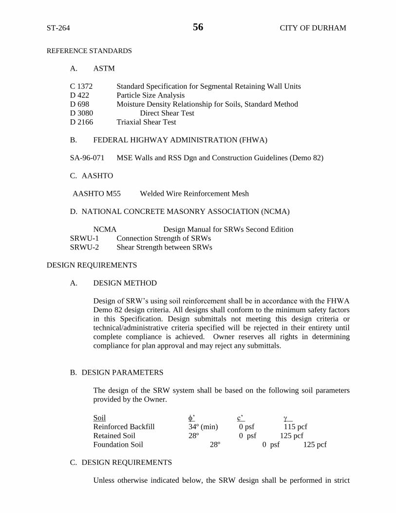
ST-264 CITY OF DURHAM
56
REFERENCE STANDARDS
A. ASTM
C 1372 Standard Specification for Segmental Retaining Wall Units
D 422 Particle Size Analysis
D 698 Moisture Density Relationship for Soils, Standard Method
D 3080 Direct Shear Test
D 2166 Triaxial Shear Test
B. FEDERAL HIGHWAY ADMINISTRATION (FHWA)
SA-96-071 MSE Walls and RSS Dgn and Construction Guidelines (Demo 82)
C. AASHTO
AASHTO M55 Welded Wire Reinforcement Mesh
D. NATIONAL CONCRETE MASONRY ASSOCIATION (NCMA)
NCMA Design Manual for SRWs Second Edition
SRWU-1 Connection Strength of SRWs
SRWU-2 Shear Strength between SRWs
DESIGN REQUIREMENTS
A. DESIGN METHOD
Design of SRW’s using soil reinforcement shall be in accordance with the FHWA
Demo 82 design criteria. All designs shall conform to the minimum safety factors
in this Specification. Design submittals not meeting this design criteria or
technical/administrative criteria specified will be rejected in their entirety until
complete compliance is achieved. Owner reserves all rights in determining
compliance for plan approval and may reject any submittals.
B. DESIGN PARAMETERS
The design of the SRW system shall be based on the following soil parameters
provided by the Owner.
Soil ’ c’
Reinforced Backfill 34º (min) 0 psf 115 pcf
Retained Soil 28º 0 psf 125 pcf
Foundation Soil 28º 0 psf 125 pcf
C. DESIGN REQUIREMENTS
Unless otherwise indicated below, the SRW design shall be performed in strict

ST-264 CITY OF DURHAM
57
compliance with Section 1.4A of this Specification.
Internal Stability Minimum Factor of Safety
Tensile Overstress 1.0 Pullout (Peak) 1.5 Facing Shear (Peak) 1.5 Facing Connection (Peak) 1.5 Uncertainties 1.5
External Stability Base Sliding (static) 1.5 Overturning 2.0 Bearing 2.0
Global 1.35
In addition, to further clarify the owner’s intent, the design shall:
1. Address hydrostatic, seismic, rapid drawdown, surcharge and backslope loading as
shown on the plans. Minimum live loads of 100 psf and 250 psf shall be for all walls
and walls supporting areas subject to traffic, respectively
2. Provide a minimum reinforcement length of 70% the total height of the wall
for each layer and minimum length of 8.0 feet. Short intermediate layers are
not allowed.
3. Provide continuous, 100% soil reinforcement coverage at each layer (no
gaps).
4. Use maximum spacing between vertically adjacent reinforcing layers of no
more than 2 times the actual (not nominal) SRW unit depth (face to tail).
5. Only the weight of the mass vertically over the plane of sliding shall be
included in the resisting forces for sliding and overturning. Submittals
The SRW contractor shall provide to the Owner a minimum of 14 days prior to the
anticipated start date for the SRW a submittal package including the following:
A. A set of detailed SRW design plans sealed by a registered professional engineer
licensed in the state of the project. The SRW plans shall include all details,
dimensions, quantities and cross sections necessary to construct the SRW and
shall include:
1. Plan, elevation and cross section views for each wall.
2. Details for cap blocks, concrete coping, or barriers constructed as part of the
wall contract.
3. Details of the SRW around all appurtenances within the wall face or
reinforced backfill, and details of connections of SRW units to sheet piling
retaining wall system.
4. Details of the SRW around the pipe penetrations.
5. Detailed hand calculations or computer output accompanied by sufficient
hand calculations demonstrating compliance with this Specification.
B. Product literature indicating specifically which SRW units and soil reinforcement

ST-264 CITY OF DURHAM
58
are proposed for use on the project including color, face style and texture.
C. Documentation for the SRW units and soil reinforcement demonstrating
compliance with the requirements of this specification including but not limited to
SRW compressive strength and absorption; SRW/soil reinforcement connection
and shear; and reinforcement creep, durability, installation damage and pullout.
D. Manufacturer’s certification that the SRW units meet the requirements of this
specification.
E. Manufacturer’s certification that the soil reinforcement meets the requirements of
this specification.
F. SRW system engineer’s certification that the design complies in all respects with
this specification and proof of current professional and general liability insurance
with an aggregate coverage of not less than $2,000,000.00 per occurrence.
G. Contractor’s certification that
1. The specific SRW system proposed for use on this project has been
successfully used on a minimum of 5 similar projects and has been
successfully installed on a minimum of 1,000,000 square feet of retaining
walls.
2. The contractor has a minimum of 200,000 square feet of experience with the
proposed SRW system. Contact names and telephone numbers shall be listed
for projects used to document the 200,000 square feet.
DELIVERY, STORAGE AND HANDLING
The contractor shall check all materials upon delivery to assure that the proper type, grade,
color and material certification have been received. Contractor shall protect materials from
damage due to jobsite conditions and in accordance with the manufacturer’s
recommendations. Damaged materials shall not be incorporated into the work.
PRODUCTS
DEFINITIONS
A. Segmental Concrete Units - a modular concrete facing unit machine made from
Portland cement, water and mineral aggregates.
B. Soil Reinforcement - steel reinforcement formed by a regular network of
integrally connected tensile elements with apertures of sufficient size to allow
interlocking with surrounding soil, rock or earth and function as reinforcement.
Soil reinforcement shall be specifically manufactured for soil reinforcement.
Steel reinforcement shall be galvanized in accordance with Section 1076 of the
North Carolina Department of Transportation Standard Specifications.

ST-264 CITY OF DURHAM
59
C. Unit Drainage Fill - drainage aggregate which is placed within and behind the
segmental concrete units.
D. Reinforced Backfill - compacted soil that is within the reinforced soil volume as
shown on the plans.
E. Foundation Soil - compacted imported or in-situ soil beneath entire wall.
F. Retained Soil - compacted imported or in-situ soil behind reinforced zone of the
retaining wall.
G. Base Leveling Pad - level compacted gravel or un-reinforced concrete pad upon
which the first course of segmental concrete facing units is placed.
H. Galvanized Pipe – structural element used to form connection between SRW units
and a separate retaining wall system.
SEGMENTAL CONCRETE UNITS SHALL MEET THE FOLLOWING REQUIREMENTS
A. Manufactured in accordance with ASTM C1372.
B. Minimum 28-day compressive strength of 3000 psi.
C. Maximum moisture absorption of 8%.
D. Dimensional tolerances shall be in accordance with ASTM C1372, but height shall
not vary more than 1/8 inch as measured from the lowest to highest point across
the top surface of the unit from a level base plane.
E. Modular units shall provide a minimum effective, in-place weight of 120 pcf
including the unit fill that is contained within the nominal dimension of the unit.
Modular units shall have a unit depth of 21.5 inches or 12 inches.
F. Units shall have angled sides capable of concave and convex alignment curves with
a minimum radius of 4.0 feet.
G. Minimum inter-unit shear strength of 500 psi at 2 psi normal pressure per NCMA
SRWU-2.
H. Minimum soil reinforcement to SRW unit peak connection strength of 500 lbs/ft at
2-psi normal pressure per NCMA SRWU-1.
I. Provide shear pins to provide a mechanical connection between vertically and
horizontally adjacent units. Shear pins shall protrude at least 1.5 inches into
receiving openings of the SRW units. At least two shear pins are required per face
unit. The shear pin must fit within an aperture of the soil reinforcement and be
capable of holding the reinforcement in the proper position during tensioning and
backfilling. The pins shall have a minimum short beam shear strength of 5000 psi.
Pins shall result in a design wall batter of between 0.5º to 2º.

ST-264 CITY OF DURHAM
60
J. SRW units finish and appearance shall be per ASTM C1372. Exposed faces shall
be free of chips, cracks or other imperfections when viewed from a distance of 20
feet under diffused lighting. Color shall be concrete gray and the face finish shall
be a sculptured rock face in an angular tri-planar configuration unless shown
otherwise on the Plans.
SOIL REINFORCEMENT
A. Soil Reinforcement - Reinforcing steel shall conform to the applicable requirements
in NCDOT Standard Specifications Sections 425 and 1070.
Shop fabricate the reinforcing strips of cold drawn steel wire conforming to the
minimum requirements of ASTM A 82 and weld into the finished strips in
accordance with ASTM A 185. Galvanize after the mesh is fabricated in
accordance with the minimum requirements of ASTM A 123.
B. Connector pins – Fabricate from cold drawn steel wire conforming to the
requirements of ASTM A 82. Galvanize in accordance with ASTM A 123.
C. Alignment/Shear pins – Utilize Alignment/Shear pins where only block to block
connections are required. Pins shall be ½” diameter thermoset isopthalic polyester
resin-pultruded fiberglass reinforcement rods. Pins shall have a minimum flexural
strength of 128,000 psi, a minimum tensile strength of 110,000 psi and a short beam
shear strength of 6400 psi.
UNIT DRAINAGE FILL AND REINFORCED BACKFILL
Shall consist of clean 1” minus crushed stone or crushed gravel meeting the requirements
for # 57 stone.
BASE LEVELING PAD
Base leveling pad shall be constructed of dense graded crushed stone or crushed gravel. A
concrete leveling pad consisting of lean unreinforced concrete may be used at the wall
contractor’s option.
Steel pipe shall conform to the requirements of ASTM A53 for galvanized standard weight steel
pipe.
EXECUTION
EXCAVATION
A. Contractor shall excavate to the lines and grades shown on the construction
drawings. Owner’s representative shall inspect the excavation and approve prior
to placement of leveling material or fill soils. Proofroll foundation area as
directed to determine if remedial work is required.
B. Over-excavation and replacement of unsuitable foundation soils and replacement

ST-264 CITY OF DURHAM
61
with approved compacted fill will be compensated as agreed upon with the Owner.
BASE LEVELING PAD
A. Leveling pad material shall be placed to the lines and grades shown on the
construction drawings, to a minimum thickness of 6 inches and extend laterally a
minimum of 6” in front and behind the SRW unit.
B. Stone leveling pads shall be compacted to a minimum of 95% Standard Proctor
density per ASTM D-698.
C. Leveling pad shall be prepared to insure full contact to the base surface of the
SRW units.
SRW UNIT INSTALLATION
First course of units shall be placed on the leveling pad at the appropriate line and grade.
Alignment and level shall be checked in all directions and insure that all units are in full
contact with the base and properly seated.
Place the front of units side-by-side. Do not leave gaps between adjacent units. Layout of
corners and curves shall be in accordance with manufacturer’s recommendations.
C. Install shear pins per manufacturer’s recommendations.
D. Place and compact drainage fill within and behind wall units. A minimum of 1
cubic foot of unit drainage fill shall be used for each square foot of wall face and
shall be placed within the cores, between and behind the SRW units and shall
extend back from the face of the wall a minimum of 2 feet. Place and compact
backfill soil behind drainage fill. Follow wall erection and drainage fill closely
with structure backfill.
E. Maximum stacked vertical height of wall units, prior to unit drainage fill and
backfill placement and compaction, shall not exceed two courses or 16 inches,
whichever is less.
SOIL REINFORCEMENT
A. Reinforcement shall be oriented with the highest strength axis perpendicular to the
wall alignment.
B. Reinforcement shall be placed at the strengths, lengths, and elevations shown on
the construction design drawings or as directed by the Engineer.
C. The reinforcement shall be laid horizontally on compacted backfill and attached to
the SRW units. Place the next course of modular concrete units over the
reinforcement. The reinforcement shall be pulled taut and anchored prior to backfill
placement. Reinforcement not meeting the minimum stiffness requirement of
Section 2.3A.6 or wider than 7 feet shall be staked at the corners and on 10 foot
centers along the roll edges to prevent wrinkling or other distortion of the

ST-264 CITY OF DURHAM
62
reinforcement during backfill placement.
D. Reinforcements shall be continuous throughout their embedment lengths and
placed side-by-side to provide 100% coverage at each level. Spliced connections
between shorter pieces of reinforcement or gaps between adjacent pieces are not
permitted.
REINFORCED BACKFILL PLACEMENT
A. Reinforced backfill shall be placed, spread, and compacted in such a manner that
minimizes the development of slack in the soil reinforcement and installation
damage.
B. Reinforced backfill shall be placed and compacted in lifts not to exceed 8 inches
where hand compaction is used or 8 to 10 inches where heavy compaction
equipment is used. Lift thickness shall be decreased to achieve the required
density as required.
Reinforced backfill shall be compacted to 95% of the maximum density as
determined by ASTM D698. The moisture content of the backfill material prior
to and during compaction shall be uniformly distributed throughout each layer
and shall be within a range of 3% below to 2% above optimum moisture content.
Only lightweight hand-operated equipment shall be allowed within 4 feet from the
face of the SRW unit.
E. Tracked construction equipment shall not be operated directly upon the
reinforcement. A minimum fill thickness of 6 inches is required prior to operation
of tracked vehicles over the reinforcing grid. Tracked vehicle turning should be
kept to a minimum to prevent tracks from displacing the fill and damaging the
reinforcement.
F. Rubber tired equipment may pass over reinforcement at slow speeds, less than 10
MPH, but should be avoided. Sudden braking and sharp turning shall be avoided.
G. At the end of each day’s operation, the Contractor shall slope the last lift of
reinforced backfill away from the wall units to direct runoff away from wall face.
The Contractor shall not allow surface runoff from adjacent areas to enter the wall
construction site.
CAP INSTALLATION
Cap units shall be glued to underlying units with an all-weather adhesive recommended by
the manufacturer.
AS-BUILT CONSTRUCTION TOLERANCES
A. Vertical Elevation Tolerance: 1.5” over any 10’ horizontal distance.

ST-264 CITY OF DURHAM
63
B. Wall Batter: 2 degrees of design batter.
C. Horizontal Alignment: 1.5” over any 10’ distance and in corners, bends and
curves 1 foot of the theoretical location.
D. Maximum horizontal gap between erected units shall be 1/2 inch.
FIELD QUALITY CONTROL AND ASSURANCE
A. Field Quality Assurance - The Owner shall engage inspection and testing services,
including independent laboratories, to provide quality assurance and testing services
during construction. As a minimum, quality assurance testing should include
foundation soil inspection, inspection for the need for any additional drainage, soil
and backfill testing, verification of design parameters, and observation of construction
for general compliance with design drawings and specifications. This does not
relieve the Contractor from securing the necessary construction quality control testing
during construction.
B. Field Quality Control - The Contractor’s quality control testing and construction
inspection services shall only be performed by qualified and experienced technicians
and engineers. The Contractor’s quality control testing, as a minimum, shall include:
1. Field Density Test
a) Subgrade: one test for every 2500 square feet of subgrade.
b) Reinforced Backfill: one test for every 2500 square feet per lift with
a minimum of one test for every other lift.
2. Laboratory Moisture Density - minimum one test per soil type.
3. Gradation Analysis - Unit and Backfill: one test per 1000 CY
TRAIL SIGN RESET:
Description
Remove and reset existing American Tobacco trail sign as indicated in the construction
drawings and details. Includes coordination, documentation of the sign’s condition,
protection of the sign and components from damage, stone removal, salvaging of stone,
locating matching stone, excavation, backfill, materials, shop drawings and labor, etc.
Materials
Includes but not limited to, new stone, sign hardware, reinforcing steel, concrete block,
concrete, anchors, new sign if existing sign is damaged, etc.
Measurement and Payment
The quantity for “Trail Sign Reset” will be paid for by Each for the signs that has been
incorporated into the work and accepted by the Engineer.

ST-264 CITY OF DURHAM
64
Payment will be made under:
Pay Item
Trail Sign Reset
Pay Unit
Lump Sum
SOLITE PARK SIGN, RELOCATE
Description
Remove and relocate existing Solite Park sign as indicated in the construction drawings
and details. Includes coordination, documentation of the sign’s condition, protection of
the sign and components from damage, excavation, backfill, materials, and labor, etc.
Materials
Includes but not limited to, concrete footing, sign hardware, reinforcing steel, new sign if
existing sign is damaged, etc.
Measurement and Payment
The quantity for “Solite Park Sign, Relocate” will be paid for by Each for the sign that
has been incorporated into the work and accepted by the Engineer.
Pay Item
Solite Park Sign, Relocate
Pay Unit
Each
METAL FENCE RESET:
Description
Remove and reset existing metal fence as indicated on the plans. Includes coordination,
demolition, excavation, backfill, materials, and labor, etc.
Materials
Includes but not limited to, new fence is damaged, hardware, concrete, anchors, etc.
Measurement and Payment
The quantity for “Metal Fence Reset” will be paid for by Lineal Foot for the fence that
has been incorporated into the work and accepted by the Engineer.
Payment will be made under:
Pay Item
Metal Fence Reset
Pay Unit
Lineal Foot
BOLLARD RESET:
Description
Remove and reset existing steel bollards as indicated on the plans. Includes coordination,
demolition, excavation, backfill, materials, and labor, etc.
Materials
Includes but not limited to, new bollard if damaged, hardware, concrete, anchors, etc.

ST-264 CITY OF DURHAM
65
Measurement and Payment
The quantity for “Bollard Reset” will be paid for as Each for each bollards that has been
incorporated into the work and accepted by the Engineer.
Payment will be made under:
Pay Item
Bollard Reset
Pay Unit
Each
NCDOT GENERAL SEED SPECIFICATION FOR SEED QUALITY (5-17-11) Z-3
Seed shall be sampled and tested by the North Carolina Department of Agriculture and Consumer
Services, Seed Testing Laboratory. When said samples are collected, the vendor shall supply an
independent laboratory report for each lot to be tested. Results from seed so sampled shall be final.
Seed not meeting the specifications shall be rejected by the Department of Transportation and shall
not be delivered to North Carolina Department of Transportation warehouses. If seed has been
delivered it shall be available for pickup and replacement at the supplier’s expense.
Any re-labeling required by the North Carolina Department of Agriculture and Consumer Services,
Seed Testing Laboratory, that would cause the label to reflect as otherwise specified herein shall
be rejected by the North Carolina Department of Transportation.
Seed shall be free from seeds of the noxious weeds Johnsongrass, Balloonvine, Jimsonweed,
Witchweed, Itchgrass, Serrated Tussock, Showy Crotalaria, Smooth Crotalaria, Sicklepod,
Sandbur, Wild Onion, and Wild Garlic. Seed shall not be labeled with the above weed species on
the seed analysis label. Tolerances as applied by the Association of Official Seed Analysts will
NOT be allowed for the above noxious weeds except for Wild Onion and Wild Garlic.
Tolerances established by the Association of Official Seed Analysts will generally be recognized.
However, for the purpose of figuring pure live seed, the found pure seed and found germination
percentages as reported by the North Carolina Department of Agriculture and Consumer Services,
Seed Testing Laboratory will be used. Allowances, as established by the NCDOT, will be
recognized for minimum pure live seed as listed on the following pages.
The specifications for restricted noxious weed seed refers to the number per pound as follows:
Restricted Noxious Limitations per Restricted Noxious Limitations per
Weed Lb. Of Seed Weed Lb. of Seed
Blessed Thistle 4 seeds Cornflower (Ragged
Robin)
27 seeds
Cocklebur 4 seeds Texas Panicum 27 seeds
Spurred Anoda 4 seeds Bracted Plantain 54 seeds
Velvetleaf 4 seeds Buckhorn Plantain 54 seeds
Morning-glory 8 seeds Broadleaf Dock 54 seeds
Corn Cockle 10 seeds Curly Dock 54 seeds
Wild Radish 12 seeds Dodder 54 seeds
Purple Nutsedge 27 seeds Giant Foxtail 54 seeds
Yellow Nutsedge 27 seeds Horsenettle 54 seeds
Canada Thistle 27 seeds Quackgrass 54 seeds

ST-264 CITY OF DURHAM
66
Field Bindweed 27 seeds Wild Mustard 54 seeds
Hedge Bindweed 27 seeds
Seed of Pensacola Bahiagrass shall not contain more than 7% inert matter, Kentucky Bluegrass,
Centipede and Fine or Hard Fescue shall not contain more than 5% inert matter whereas
a maximum of 2% inert matter will be allowed on all other kinds of seed. In addition, all seed
shall not contain more than 2% other crop seed nor more than 1% total weed seed. The germination
rate as tested by the North Carolina Department of Agriculture shall not fall below 70%, which
includes both dormant and hard seed. Seed shall be labeled with not more than 7%, 5% or 2%
inert matter (according to above specifications), 2% other crop seed and 1% total weed seed.
Exceptions may be made for minimum pure live seed allowances when cases of seed variety
shortages are verified. Pure live seed percentages will be applied in a verified shortage situation.
Those purchase orders of deficient seed lots will be credited with the percentage that the seed is
deficient.
FURTHER SPECIFICATIONS FOR EACH SEED GROUP ARE GIVEN BELOW:
Minimum 85% pure live seed; maximum 1% total weed seed; maximum 2% total other crop seed;
maximum 144 restricted noxious weed seed per pound. Seed less than 83% pure live seed will not
be approved.
Sericea Lespedeza
Oats (seeds)
Minimum 80% pure live seed; maximum 1% total weed seed; maximum 2% total other crop;
maximum 144 restricted noxious weed seed per pound. Seed less than 78% pure live seed will not
be approved.
Tall Fescue (all approved varieties) Bermudagrass
Kobe Lespedeza Browntop Millet
Korean Lespedeza German Millet – Strain R
Weeping Lovegrass Clover – Red/White/Crimson
Carpetgrass
Minimum 78% pure live seed; maximum 1% total weed seed; maximum 2% total other crop seed;
maximum 144 restricted noxious weed seed per pound. Seed less than 76% pure live seed will not
be approved.
Common or Sweet Sundangrass
Minimum 76% pure live seed; maximum 1% total weed seed; maximum 2% total other crop seed;
maximum 144 restricted noxious weed seed per pound. Seed less than 74% pure live seed will not
be approved.
Rye (grain; all varieties)
Kentucky Bluegrass (all approved varieties)
Hard Fescue (all approved varieties)
Shrub (bicolor) Lespedeza

ST-264 CITY OF DURHAM
67
Minimum 70% pure live seed; maximum 1% total weed seed; maximum 2% total other crop seed;
maximum 144 noxious weed seed per pound. Seed less than 70% pure live seed will not be
approved.
Centipedegrass Japanese Millet
Crownvetch Reed Canary Grass
Pensacola Bahiagrass Zoysia
Creeping Red Fescue
Minimum 70% pure live seed; maximum 1% total weed seed; maximum 2% total other crop seed;
maximum 5% inert matter; maximum 144 restricted noxious weed seed per pound.
Barnyard Grass
Big Bluestem
Little Bluestem
Bristly Locust
Birdsfoot Trefoil
Indiangrass
Orchardgrass
Switchgrass
Yellow Blossom Sweet Clover

ST-264 CITY OF DURHAM
68
ADJUSTMENT OF MANHOLES: SP8 R95R
The Contractor's attention is directed to Section 858-3 of the 2018 Standard Specifications.
The use of cast iron or steel fittings in the adjustment of manholes will not be permitted on this
project except where it is considered by the Engineer to be in the best interest of the Department
to allow rings to be used. When rings are permitted for the adjustment of manholes, the rings shall
have satisfactory bearing on the existing manhole frames and 50 percent of the circumference shall
be tack welded at four equally spaced locations as directed by the Engineer. If the existing covers
do not fit the rings, furnish and install new covers at no additional expense to the Department.
ERRATA (2-12-18) Z-4
Revise the 2018 Standard Specifications as follows:
Division 7
Page 7-27, line 4, Article 725-1 MEASUREMENT AND PAYMENT, replace article number “725-1”
with “724-4”.
Page 7-28, line 10, Article 725-1 MEASUREMENT AND PAYMENT, replace article number “725-1”
with “725-3”.
Division 10
Page 10-162, line 1, Article 1080-50 PAINT FOR VERTICAL MARKERS, replace article number
“1080-50” with “1080-10”.
Page 10-162, line 5, Article 1080-61 EPOXY RESIN FOR REINFORCING STEEL, replace article
number “1080-61” with “1080-11”.
Page 10-162, line 22, Article 1080-72 ABRASIVE MATERIALS FOR BLAST CLEANING STEEL,
replace article number “1080-72” with “1080-12”.
Page 10-163, line 25, Article 1080-83 FIELD PERFORMANCE AND SERVICES, replace article
number “1080-83” with “1080-13”.

ST-264 CITY OF DURHAM
69
PLANT AND PEST QUARANTINES
(Imported Fire Ant, Gypsy Moth, Witchweed, Emerald Ash Borer, And Other Noxious
Weeds) (3-18-03) (Rev. 12-20-16) Z-04a
Within Quarantined Area
This project may be within a county regulated for plant and/or pests. If the project or any part of
the Contractor's operations is located within a quarantined area, thoroughly clean all equipment
prior to moving out of the quarantined area. Comply with federal/state regulations by obtaining a
certificate or limited permit for any regulated article moving from the quarantined area.
Originating in a Quarantined County
Obtain a certificate or limited permit issued by the N.C. Department of Agriculture/United States
Department of Agriculture. Have the certificate or limited permit accompany the article when it
arrives at the project site.
Contact
Contact the N.C. Department of Agriculture/United States Department of Agriculture
at 1-800-206-9333, 919-707-3730, or http://www.ncagr.gov/plantindustry/ to determine those
specific project sites located in the quarantined area or for any regulated article used on this project
originating in a quarantined county.
Regulated Articles Include
1. Soil, sand, gravel, compost, peat, humus, muck, and decomposed manure, separately or with
other articles. This includes movement of articles listed above that may be associated with
cut/waste, ditch pulling, and shoulder cutting.
2. Plants with roots including grass sod.
3. Plant crowns and roots.
4. Bulbs, corms, rhizomes, and tubers of ornamental plants.
5. Hay, straw, fodder, and plant litter of any kind.
6. Clearing and grubbing debris.
7. Used agricultural cultivating and harvesting equipment.
8. Used earth-moving equipment.
9. Any other products, articles, or means of conveyance, of any character, if determined by an
inspector to present a hazard of spreading imported fire ant, gypsy moth, witchweed, emerald
ash borer, or other noxious weeds.
TRAFFIC SIGNALS:………………………………………………..TS-1 THROUGH TS-83

TIP Number TS-1 Durham County
Version 18.1 1 print date: 03/07/18
Signals and Intelligent Transportation Systems
Project Special Provisions
(Version 18.1)
Prepared By: SLP/KWS
7-Mar-18
Contents
1. 2018 STANDARD SPECIFICATIONS FOR ROADS & STRUCTURES ........................................................................... 4
1.1. GENERAL REQUIREMENTS – CONSTRUCTION METHODS (1700-3(K))........................................................ 4
1.2. WOOD POLES – CONSTRUCTION METHODS (1720-3) .................................................................................... 4
2. SIGNAL HEADS ................................................................................................................................................ 4
2.1. MATERIALS ................................................................................................................................................ 4A. General:....................................................................................................................................................... 4
B. Vehicle Signal Heads: .................................................................................................................................. 6
C. Pedestrian Signal Heads: ............................................................................................................................. 9
D. Signal Cable: ............................................................................................................................................. 10
E. Optically-Programmed Vehicle Signal Sections: ......................................................................................... 11
F. Louvers: ..................................................................................................................................................... 11
3. CONTROLLERS WITH CABINETS ............................................................................................................. 12
3.1. MATERIALS – GENERAL CABINETS ...................................................................................................... 12
3.2. MATERIALS – TYPE 170E CABINETS ..................................................................................................... 13
A. Type 170 E Cabinets General: .................................................................................................................... 13
B. Type 170 E Cabinet Electrical Requirements: ............................................................................................. 13
C. Type 170 E Cabinet Physical Requirements: ............................................................................................... 21
D. Model 2018 Enhanced Conflict Monitor: .................................................................................................... 23
E. Preemption and Sign Control Box ............................................................................................................... 33
3.3. MATERIALS – TYPE 170 DETECTOR SENSOR UNITS ........................................................................... 36
3.4. MATERIALS – TYPE 2070E CONTROLLERS ........................................................................................... 36
4. TRAFFIC SIGNAL SUPPORTS ..................................................................................................................... 37
4.1. METAL TRAFFIC SIGNAL SUPPORTS – ALL POLES ............................................................................. 37
A. General:..................................................................................................................................................... 37
B. Materials: .................................................................................................................................................. 39
C. Construction Methods: ............................................................................................................................... 40
4.2. METAL POLE UPRIGHTS (VERTICAL MEMBERS) ................................................................................ 40A. Materials: .................................................................................................................................................. 40
4.3. STRAIN POLE SHAFTS ............................................................................................................................. 42
4.4. MAST ARM POLE SHAFTS ....................................................................................................................... 42
A. Construction Methods: ............................................................................................................................... 42
4.5. MAST ARMS .............................................................................................................................................. 42
A. Materials: .................................................................................................................................................. 43
B. Construction Methods: ............................................................................................................................... 43
4.6. DRILLED PIER FOUNDATIONS FOR METAL TRAFFIC SIGNAL POLES ................................................................. 43
A. Description: ............................................................................................................................................... 44
B. Soil Test and Foundation Determination: ................................................................................................... 44
Document not considered finalunless all signatures completed.
3/7/2018

TIP Number TS-2 Durham County
Version 18.1 2 print date: 03/07/18
C. Drilled Pier Construction: .......................................................................................................................... 46
4.7. CUSTOM DESIGN OF TRAFFIC SIGNAL SUPPORTS ............................................................................................ 47
A. General:..................................................................................................................................................... 47
B. Metal Poles: ............................................................................................................................................... 48
C. Mast Arms: ................................................................................................................................................ 504.8. METAL SIGNAL POLE REMOVALS ........................................................................................................ 50
A. Description: ............................................................................................................................................... 50
B. Construction Methods: ............................................................................................................................... 50
4.9. POLE NUMBERING SYSTEM ................................................................................................................... 51
A. New Poles .................................................................................................................................................. 51
B. Reused Poles .............................................................................................................................................. 51
4.10. REUSED POLE SHAFTS AND/OR MAST ARMS ...................................................................................... 51
4.11. MEASUREMENT AND PAYMENT ........................................................................................................... 51
5. BACK PULL FIBER OPTIC CABLE ............................................................................................................. 53
5.1. DESCRIPTION ........................................................................................................................................... 53
5.2. CONSTRUCTION ....................................................................................................................................... 53
5.3. MEASUREMENT AND PAYMENT ........................................................................................................... 53
6. REMOVAL AND RELOCATION OF EXISTING EQUIPMENT ................................................................ 54
6.1. DESCRIPTION ........................................................................................................................................... 54
6.2. CONSTRUCTION METHODS .................................................................................................................... 54
A. CCTV Site Overview ................................................................................................................................... 54
B. Wireless Site Overview ............................................................................................................................... 54
C. Relocate Existing CCTV Camera Assembly ................................................................................................. 54
D. Relocate Existing Field Equipment Cabinet ................................................................................................ 55
E. Relocate Existing Communications Equipment ............................................................................................ 55
F. Relocate Existing Electrical Service ............................................................................................................ 56
G. Remove Existing Wood Pole ....................................................................................................................... 56
H. Relocate Existing Wireless Radio Equipment .............................................................................................. 566.3. MEASUREMENT AND PAYMENT ..................................................................................................................... 56
7. CCTV EQUIPMENT ....................................................................................................................................... 58
7.1. DESCRIPTION ................................................................................................................................................ 58
7.2. MATERIAL.................................................................................................................................................... 58
A. General ...................................................................................................................................................... 58
B. Camera and Lens ....................................................................................................................................... 58C. CCTV Camera Attachment to Pole.............................................................................................................. 60
D. Surge Suppression ...................................................................................................................................... 60
7.3. CONSTRUCTION METHODS ............................................................................................................................ 60
A. General ...................................................................................................................................................... 60
B. Electrical and Mechanical Requirements .................................................................................................... 60
7.4. MEASUREMENT AND PAYMENT ........................................................................................................... 61
8. CCTV FIELD EQUIPMENT CABINET ........................................................................................................ 61
8.1. DESCRIPTION ................................................................................................................................................ 61
8.2. MATERIAL.................................................................................................................................................... 62
A. Shelf Drawer .............................................................................................................................................. 62
B. Cabinet Light ............................................................................................................................................. 62
C. Surge Protection for System Equipment ...................................................................................................... 62
8.3. CONSTRUCTION METHODS ............................................................................................................................ 64
8.4. MEASUREMENT AND PAYMENT ........................................................................................................... 64
9. CCTV METAL POLES ................................................................................................................................... 65
9.1. CCTV METAL POLES.................................................................................................................................... 65
A. General:..................................................................................................................................................... 65
B. Materials: .................................................................................................................................................. 66
C. Construction Methods: ............................................................................................................................... 67

TIP Number TS-3 Durham County
Version 18.1 3 print date: 03/07/18
9.2. DRILLED PIER FOUNDATIONS ........................................................................................................................ 68
A. Description: ............................................................................................................................................... 68
B. Soil Test and Foundation Determination: ................................................................................................... 69
C. Drilled Pier Construction: .......................................................................................................................... 71
9.3. MEASUREMENT AND PAYMENT ........................................................................................................... 71
10. FOUNDATIONS AND ANCHOR ROD ASSEMBLIES FOR METAL POLES ............................................. 72
10.1. DESCRIPTION ................................................................................................................................................ 72
10.2. MATERIAL.................................................................................................................................................... 72
10.3. CONSTRUCTION METHODS ............................................................................................................................ 73
A. Drilled Piers .............................................................................................................................................. 73
D. Footings, Pedestals, Grade Beams and Wings ............................................................................................. 75E. Anchor Rod Assemblies .............................................................................................................................. 75
10.4. MEASUREMENT AND PAYMENT ..................................................................................................................... 77
11. ELECTRICAL SERVICE ............................................................................................................................... 78
11.1. DESCRIPTION ........................................................................................................................................... 78
11.2. MATERIAL ................................................................................................................................................ 78
A. Electrical Service ....................................................................................................................................... 78B. Grounding Electrodes ................................................................................................................................ 78
11.3. CONSTRUCTION METHODS .................................................................................................................... 79
A. Utility Services ........................................................................................................................................... 79
B. New Electrical Service ............................................................................................................................... 79
C. Grounding of Electrical Services ................................................................................................................ 79
11.4. MEASUREMENT AND PAYMENT ........................................................................................................... 80
12. FIBER OPTIC VIDEO TRANSCEIVERS ...................................................................................................... 80
12.1. DESCRIPTION ................................................................................................................................................ 80
12.2. MATERIALS .................................................................................................................................................. 80
A. Video Transceivers ..................................................................................................................................... 80
12.3. CONSTRUCTION METHODS ............................................................................................................................ 83
12.4. MEASUREMENT AND PAYMENT ..................................................................................................................... 83

TIP Number TS-4 Durham County
Version 18.1 4 print date: 03/07/18
1. 2018 STANDARD SPECIFICATIONS FOR ROADS & STRUCTURES
The 2018 Standard Specifications are revised as follows:
1.1. GENERAL REQUIREMENTS – CONSTRUCTION METHODS (1700-3(K))
Page 17-4, revise sentence starting on line 14 to read “Modify existing electrical services, as
necessary, to meet the grounding requirements of the NEC, these Standard Specifications, Standard
Drawings, and the project plans.”
Page 17-4, revise sentence beginning on line 21 to read “Furnish and install additional ground rods
to grounding electrode system as necessary to meet the Standard Specifications, Standard Drawings,
and test requirements.”
1.2. WOOD POLES – CONSTRUCTION METHODS (1720-3)
Page 17-18, revise sentence starting on line 13 to read “On new Department-owned poles, install a
grounding system consisting of #6 AWG solid bare copper wire that is mechanically crimped using
an irreversible compression tool with die to a single ground rod installed at base of pole or to the
electrical service grounding electrode system located within 10 feet of the pole.”
2. SIGNAL HEADS
2.1. MATERIALS
A. General:
Fabricate vehicle signal head housings and end caps from die-cast aluminum. Fabricate 12-inch
and 16-inch pedestrian signal head housings and end caps from die-cast aluminum. Fabricate 9-inch
pedestrian signal head housings, end caps, and visors from virgin polycarbonate material. Provide
visor mounting screws, door latches, and hinge pins fabricated from stainless steel. Provide interior
screws, fasteners, and metal parts fabricated from stainless steel.
Fabricate tunnel and traditional visors from sheet aluminum.
Paint all surfaces inside and outside of signal housings and doors. Paint outside surfaces of
tunnel and traditional visors, wire outlet bodies, wire entrance fitting brackets and end caps when
supplied as components of messenger cable mounting assemblies, pole and pedestal mounting
assemblies, and pedestrian pushbutton housings. Have electrostatically-applied, fused-polyester
paint in highway yellow (Federal Standard 595C, Color Chip Number 13538) a minimum of 2.5 to
3.5 mils thick. Do not apply paint to the latching hardware, rigid vehicle signal head mounting
brackets for mast-arm attachments, messenger cable hanger components or balance adjuster
components.
Have the interior surfaces of tunnel and traditional visors painted an alkyd urea black synthetic
baking enamel with a minimum gloss reflectance and meeting the requirements of MIL-E-10169,
“Enamel Heat Resisting, Instrument Black.”
Where required, provide polycarbonate signal heads and visors that comply with the provisions
pertaining to the aluminum signal heads listed on the QPL with the following exceptions:
Fabricate signal head housings, end caps, and visors from virgin polycarbonate material. Provide
UV stabilized polycarbonate plastic with a minimum thickness of 0.1 ± 0.01 inches that is
highway yellow (Federal Standard 595C, Color Chip 13538). Ensure the color is incorporated

TIP Number TS-5 Durham County
Version 18.1 5 print date: 03/07/18
into the plastic material before molding the signal head housings and end caps. Ensure the plastic
formulation provides the following physical properties in the assembly (tests may be performed
on separately molded specimens):
Test Required Method
Specific Gravity 1.17 minimum ASTM D 792
Flammability Self-extinguishing ASTM D 635
Tensile Strength, yield, PSI 8500 minimum ASTM D 638
Izod impact strength, ft-lb/in [notched, 1/8 inch] 12 minimum ASTM D 256
For pole mounting, provide side of pole mounting assemblies with framework and all other
hardware necessary to make complete, watertight connections of the signal heads to the poles and
pedestals. Fabricate the mounting assemblies and frames from aluminum with all necessary
hardware, screws, washers, etc. to be stainless steel. Provide mounting fittings that match the
positive locking device on the signal head with the serrations integrally cast into the brackets.
Provide upper and lower pole plates that have a 1 ¼-inch vertical conduit entrance hubs with the
hubs capped on the lower plate and 1 ½-inch horizontal hubs. Ensure that the assemblies provide
rigid attachments to poles and pedestals so as to allow no twisting or swaying of the signal heads.
Ensure that all raceways are free of sharp edges and protrusions, and can accommodate a minimum
of ten Number 14 AWG conductors.
For pedestal mounting, provide a post-top slipfitter mounting assembly that matches the positive
locking device on the signal head with serrations integrally cast into the slipfitter. Provide stainless
steel hardware, screws, washers, etc. Provide a minimum of six 3/8 X 3/4-inch long square head
bolts for attachment to pedestal. Provide a center post for multi-way slipfitters.
For light emitting diode (LED) traffic signal modules, provide the following requirements for
inclusion on the Department’s Qualified Products List for traffic signal equipment.
1. Sample submittal,
2. Third-party independent laboratory testing results for each submitted module with evidence of
testing and conformance with all of the Design Qualification Testing specified in section 6.4
of each of the following Institute of Transportation Engineers (ITE) specifications:
· Vehicle Traffic Control Signal Heads – Light Emitting Diode (LED) Circular Signal
Supplement
· Vehicle Traffic Control Signal Heads – Light Emitting Diode (LED) Vehicle Arrow
Traffic Signal Supplement
· Pedestrian Traffic Control Signal Indications –Light Emitting Diode (LED) Signal
Modules.
(Note: The Department currently recognizes two approved independent testing laboratories.
They are Intertek ETL Semko and Light Metrics, Incorporated with Garwood Laboratories.
Independent laboratory tests from other laboratories may be considered as part of the QPL
submittal at the discretion of the Department,
3. Evidence of conformance with the requirements of these specifications,
4. A manufacturer’s warranty statement in accordance with the required warranty, and

TIP Number TS-6 Durham County
Version 18.1 6 print date: 03/07/18
5. Submittal of manufacturer’s design and production documentation for the model, including
but not limited to, electrical schematics, electronic component values, proprietary part
numbers, bill of materials, and production electrical and photometric test parameters.
6. Evidence of approval of the product to bear the Intertek ETL Verified product label for LED
traffic signal modules.
In addition to meeting the performance requirements for the minimum period of 60 months,
provide a written warranty against defects in materials and workmanship for the modules for a
period of 60 months after installation of the modules. During the warranty period, the manufacturer
must provide new replacement modules within 45 days of receipt of modules that have failed at no
cost to the State. Repaired or refurbished modules may not be used to fulfill the manufacturer’s
warranty obligations. Provide manufacturer’s warranty documentation to the Department during
evaluation of product for inclusion on Qualified Products List (QPL).
B. Vehicle Signal Heads:
Comply with the ITE standard “Vehicle Traffic Control Signal Heads”. Provide housings with
provisions for attaching backplates.
Provide visors that are 8 inches in length for 8-inch vehicle signal head sections. Provide visors
that are 10 inches in length for 12-inch vehicle signal heads.
Provide a termination block with one empty terminal for field wiring for each indication plus one
empty terminal for the neutral conductor. Have all signal sections wired to the termination block.
Provide barriers between the terminals that have terminal screws with a minimum Number 8 thread
size and that will accommodate and secure spade lugs sized for a Number 10 terminal screw.
Mount termination blocks in the yellow signal head sections on all in-line vehicle signal heads.
Mount the termination block in the red section on five-section vehicle signal heads.
Furnish vehicle signal head interconnecting brackets. Provide one-piece aluminum brackets less
than 4.5 inches in height and with no threaded pipe connections. Provide hand holes on the bottom
of the brackets to aid in installing wires to the signal heads. Lower brackets that carry no wires and
are used only for connecting the bottom signal sections together may be flat in construction.
For messenger cable mounting, provide messenger cable hangers, wire outlet bodies, balance
adjusters, bottom caps, wire entrance fitting brackets, and all other hardware necessary to make
complete, watertight connections of the vehicle signal heads to the messenger cable. Fabricate
messenger cable hanger components, wire outlet bodies and balance adjuster components from
stainless steel or malleable iron galvanized in accordance with ASTM A153 (Class A) or ASTM
A123. Provide serrated rings made of aluminum. Provide messenger cable hangers with U-bolt
clamps. Fabricate washers, screws, hex-head bolts and associated nuts, clevis pins, cotter pins, U-
bolt clamps and nuts from stainless steel.
For mast-arm mounting, provide rigid vehicle signal head mounting brackets and all other
hardware necessary to make complete, watertight connections of the vehicle signal heads to the mast
arms and to provide a means for vertically adjusting the vehicle signal heads to proper alignment.
Fabricate the mounting assemblies from aluminum, and provide serrated rings made of aluminum.
Provide stainless steel cable attachment assemblies to secure the brackets to the mast arms. Ensure
all fastening hardware and fasteners are fabricated from stainless steel.

TIP Number TS-7 Durham County
Version 18.1 7 print date: 03/07/18
Provide LED vehicular traffic signal modules (hereafter referred to as modules) that consist of an
assembly that uses LEDs as the light source in lieu of an incandescent lamp for use in traffic signal
sections. Use LEDs that are aluminum indium gallium phosphorus (AlInGaP) technology for red and
yellow indications and indium gallium nitride (InGaN) for green indications. Install the ultra bright
type LEDs that are rated for 100,000 hours of continuous operation from -40°F to +165°F. Design
modules to have a minimum useful life of 60 months and to meet all parameters of this specification
during this period of useful life.
For the modules, provide spade terminals crimped to the lead wires and sized for a #10 screw
connection to the existing terminal block in a standard signal head. Do not provide other types of
crimped terminals with a spade adapter.
Ensure the power supply is integral to the module assembly. On the back of the module,
permanently mark the date of manufacture (month & year) or some other method of identifying date
of manufacture.
Tint the red, yellow and green lenses to correspond with the wavelength (chromaticity) of the
LED. Transparent tinting films are unacceptable. Provide a lens that is integral to the unit with a
smooth outer surface.
1. LED Circular Signal Modules:
Provide modules in the following configurations: 12-inch circular sections, and 8-inch circular
sections. All makes and models of LED modules purchased for use on the State Highway System
shall appear on the current NCDOT Traffic Signal Qualified Products List (QPL).
Provide the manufacturer’s model number and the product number (assigned by the Department)
for each module that appears on the 2018 or most recent Qualified Products List. In addition, provide
manufacturer’s certification in accordance with Article 106-3 of the Standard Specifications, that
each module meets or exceeds the ITE “Vehicle Traffic Control Signal Heads – Light Emitting
Diode (LED) Circular Signal Supplement” dated June 27, 2005 (hereafter referred to as VTCSH
Circular Supplement) and other requirements stated in this specification.
Provide modules that meet the following requirements when tested under the procedures outlined
in the VTCSH Circular Supplement:
Module Type Max. Wattage at 165° F Nominal Wattage at 77° F
12-inch red circular 17 11
8-inch red circular 13 8
12-inch green circular 15 15
8-inch green circular 12 12
For yellow circular signal modules, provide modules tested under the procedures outlined in the
VTCSH Circular Supplement to insure power required at 77° F is 22 Watts or less for the 12-inch
circular module and 13 Watts or less for the 8-inch circular module.
Note: Use a wattmeter having an accuracy of ±1% to measure the nominal wattage and
maximum wattage of a circular traffic signal module. Power may also be derived from voltage,
current and power factor measurements.

TIP Number TS-8 Durham County
Version 18.1 8 print date: 03/07/18
2. LED Arrow Signal Modules
Provide 12-inch omnidirectional arrow signal modules. All makes and models of LED modules
purchased for use on the State Highway System shall appear on the current NCDOT Traffic Signal
Qualified Products List (QPL).
Provide the manufacturer’s model number and the product number (assigned by the Department)
for each module that appears on the 2018 or most recent Qualified Products List. In addition, provide
manufacturer’s certification in accordance with Article 106-3 of the Standard Specifications, that
each module meets or exceeds the requirements for 12-inch omnidirectional modules specified in the
ITE “Vehicle Traffic Control Signal Heads – Light Emitting Diode (LED) Vehicle Arrow Traffic
Signal Supplement” dated July 1, 2007 (hereafter referred to as VTCSH Arrow Supplement) and
other requirements stated in this specification.
Provide modules that meet the following requirements when tested under the procedures outlined
in the VTCSH Arrow Supplement:
Module Type Max. Wattage at 165° F Nominal Wattage at 77° F
12-inch red arrow 12 9
12-inch green arrow 11 11
For yellow arrow signal modules, provide modules tested under the procedures outlined in the
VTCSH Arrow Supplement to insure power required at 77° F is 12 Watts or less.
Note: Use a wattmeter having an accuracy of ±1% to measure the nominal wattage and
maximum wattage of an arrow traffic signal module. Power may also be derived from voltage,
current and power factor measurements.
3. LED U-Turn Arrow Signal Modules:
Provide modules in the following configurations: 12-inch left u-turn arrow signal modules and
12-inch right u-turn arrow signal modules.
Modules are not required to be listed on the ITS and Signals Qualified Products List. Provide
manufacturer’s certification in accordance with Article 106-3 of the Standard Specifications, that
each module meets or exceeds the ITE “Vehicle Traffic Control Signal Heads – Light Emitting
Diode (LED) Circular Signal Supplement” dated June 27, 2005 (hereafter referred to as VTCSH
Circular Supplement) and other requirements stated in this specification.
Provide modules that have minimum maintained luminous intensity values that are not less than
16% of the values calculated using the method described in section 4.1 of the VTCSH Circular
Supplement.
Provide modules that meet the following requirements when tested under the procedures outlined
in the VTCSH Circular Supplement:
Module Type Max. Wattage at 165° F Nominal Wattage at 77° F
12-inch red u-turn arrow 17 11
12-inch green u-turn arrow 15 15
For yellow u-turn arrow signal modules, provide modules tested under the procedures outlined in
the VTCSH Circular Supplement to ensure power required at 77° F is 22 Watts or less.

TIP Number TS-9 Durham County
Version 18.1 9 print date: 03/07/18
Note: Use a wattmeter having an accuracy of ±1% to measure the nominal wattage and
maximum wattage of a circular traffic signal module. Power may also be derived from voltage,
current and power factor measurements.
C. Pedestrian Signal Heads:
Provide pedestrian signal heads with international symbols that meet the MUTCD. Do not
provide letter indications.
Comply with the ITE standard for “Pedestrian Traffic Control Signal Indications” and the
following sections of the ITE standard for “Vehicle Traffic Control Signal Heads” in effect on the
date of advertisement:
· Section 3.00 - “Physical and Mechanical Requirements”
· Section 4.01 - “Housing, Door, and Visor: General”
· Section 4.04 - “Housing, Door, and Visor: Materials and Fabrication”
· Section 7.00 - “Exterior Finish”
Provide a double-row termination block with three empty terminals and number 10 screws for
field wiring. Provide barriers between the terminals that accommodate a spade lug sized for number
10 terminal screws. Mount the termination block in the hand section. Wire all signal sections to the
terminal block.
Where required by the plans, provide 16-inch pedestrian signal heads with traditional three-
sided, rectangular visors, 6 inches long. Where required by the plans, provide 12-inch pedestrian
signal heads with traditional three-sided, rectangular visors, 8 inches long.
Provide 2-inch diameter pedestrian push-buttons with weather-tight housings fabricated from
die-cast aluminum and threading in compliance with the NEC for rigid metal conduit. Provide a
weep hole in the housing bottom and ensure that the unit is vandal resistant.
Provide push-button housings that are suitable for mounting on flat or curved surfaces and that
will accept 1/2-inch conduit installed in the top. Provide units that have a heavy duty push-button
assembly with a sturdy, momentary, normally-open switch. Have contacts that are electrically
insulated from the housing and push-button. Ensure that the push-buttons are rated for a minimum of
5 mA at 24 volts DC and 250 mA at 12 volts AC.
Provide standard R10-3 signs with mounting hardware that comply with the MUTCD in effect
on the date of advertisement. Provide R10-3E signs for countdown pedestrian heads and R10-3B for
non-countdown pedestrian heads.
Design the LED pedestrian traffic signal modules (hereafter referred to as modules) for
installation into standard pedestrian traffic signal sections that do not contain the incandescent signal
section reflector, lens, eggcrate visor, gasket, or socket. Provide modules that consist of an assembly
that uses LEDs as the light source in lieu of an incandescent lamp. Use LEDs that are of the latest
aluminum indium gallium phosphorus (AlInGaP) technology for the Portland Orange hand and
countdown displays. Use LEDs that are of the latest indium gallium nitride (InGaN) technology for
the Lunar White walking man displays. Install the ultra-bright type LEDs that are rated for 100,000
hours of continuous operation from -40°F to +165°F. Design modules to have a minimum useful life
of 60 months and to meet all parameters of this specification during this period of useful life.

TIP Number TS-10 Durham County
Version 18.1 10 print date: 03/07/18
Design all modules to operate using a standard 3 - wire field installation. Provide spade
terminals crimped to the lead wires and sized for a #10 screw connection to the existing terminal
block in a standard pedestrian signal housing. Do not provide other types of crimped terminals with
a spade adapter.
Ensure the power supply is integral to the module assembly. On the back of the module,
permanently mark the date of manufacture (month & year) or some other method of identifying date
of manufacture.
Provide modules in the following configuration: 16-inch displays which have the solid
hand/walking man overlay on the left and the countdown on the right, and 12-inch displays which
have the solid hand/walking man module as an overlay. All makes and models of LED modules
purchased for use on the State Highway System shall appear on the current NCDOT Traffic Signal
Qualified Products List (QPL).
Provide the manufacturer’s model number and the product number (assigned by the Department)
for each module that appears on the 2018 or most recent Qualified Products List. In addition, provide
manufacturer’s certification in accordance with Article 106-3 of the Standard Specifications, that
each module meets or exceeds the ITE “Pedestrian Traffic Control Signal Indicators - Light Emitting
Diode (LED) Signal Modules” dated August 04, 2010 (hereafter referred to as PTCSI Pedestrian
Standard) and other requirements stated in this specification.
Provide modules that meet the following requirements when tested under the procedures outlined
in the PTCSI Pedestrian Standard:
Module Type Max. Wattage at 165° F Nominal Wattage at 77° F
Hand Indication 16 13
Walking Man Indication 12 9
Countdown Indication 16 13
Note: Use a wattmeter having an accuracy of ±1% to measure the nominal wattage and
maximum wattage of a circular traffic signal module. Power may also be derived from voltage,
current and power factor measurements.
Provide module lens that is hard coated or otherwise made to comply with the material exposure
and weathering effects requirements of the Society of Automotive Engineers (SAE) J576. Ensure all
exposed components of the module are suitable for prolonged exposure to the environment, without
appreciable degradation that would interfere with function or appearance.
Ensure the countdown display continuously monitors the traffic controller to automatically learn
the pedestrian phase time and update for subsequent changes to the pedestrian phase time.
Ensure the countdown display begins normal operation upon the completion of the preemption
sequence and no more than one pedestrian clearance cycle.
D. Signal Cable:
Furnish 16-4 and 16-7 signal cable that complies with IMSA specification 20-1 except provide
the following conductor insulation colors:
· For 16-4 cable: white, yellow, red, and green

TIP Number TS-11 Durham County
Version 18.1 11 print date: 03/07/18
· For 16-7 cable: white, yellow, red, green, yellow with black stripe tracer, red with black
stripe tracer, and green with black stripe tracer. Apply continuous stripe tracer on conductor
insulation with a longitudinal or spiral pattern.
Provide a ripcord to allow the cable jacket to be opened without using a cutter. IMSA
specification 19-1 will not be acceptable. Provide a cable jacket labeled with the IMSA specification
number and provide conductors constructed of stranded copper.
E. Optically-Programmed Vehicle Signal Sections:
Material, equipment, and hardware furnished under this section must be pre-approved on the
Department’s QPL by the date of installation.
Design the programmable signal sections to tilt in two degree increments for a maximum of ten
degrees above and ten degrees below horizontal, while still maintaining a common vertical axis.
Design the programmable signal sections to mount to standard signal sections to form a signal
head. Ensure that the programmable signal sections have a mounting system compatible with the
standard 1 ½-inch traffic signal fittings.
Provide an optical system consisting of a lamp, a diffuser, an optical limiter, and an objective
lens. Ensure that all programming is accomplished optically with no hoods or louvers necessary to
accomplish the programming. Provide optical masking tape with each section.
Provide a 150-Watt, 115 VAC lamp with integral reflector and rated output of 1750 lumens.
Ensure that the average rated life is at least 6000 hours.
Provide a high resolution, annular, incremental lens. Ensure that the lens and door are sealed to
provide a moisture and dust proof seal. Provide a red, yellow, or green ball or arrow indication as
specified by the bid list, plans, or purchase order.
F. Louvers:
Material, equipment, and hardware furnished under this section must be pre-approved on the
Department’s QPL by the date of installation.
Provide louvers made from sheet aluminum. Paint the louvers alkyd urea black synthetic baked
enamel with a minimum gloss reflectance and meeting the requirements of MIL-E-10169, “Enamel
Heat Resisting, Instrument Black.”
Ensure that the louvers have a 0-degree horizontal viewing angle. Provide a minimum of 5
vanes.

TIP Number TS-12 Durham County
Version 18.1 12 print date: 03/07/18
3. CONTROLLERS WITH CABINETS
3.1. MATERIALS – GENERAL CABINETS
Provide a moisture resistant coating on all circuit boards.
Provide one 20 mm diameter radial lead UL-recognized metal oxide varistor (MOV) between
each load switch field terminal and equipment ground. Electrical performance is outlined below.
PROPERTIES OF MOV SURGE PROTECTOR
Maximum Continuous Applied Voltage at
185° F
150 VAC (RMS)
200 VDC
Maximum Peak 8x20µs Current at 185° F 6500 A
Maximum Energy Rating at 185° F 80 J
Voltage Range 1 mA DC Test at 77° F 212-268 V
Max. Clamping Voltage 8x20µs, 100A at
77° F395 V
Typical Capacitance (1 MHz) at 77° F 1600 pF
Provide a power line surge protector that is a two-stage device that will allow connection of the
radio frequency interference filter between the stages of the device. Ensure that a maximum
continuous current is at least 10A at 120V. Ensure that the device can withstand a minimum of 20
peak surge current occurrences at 20,000A for an 8x20 microsecond waveform. Provide a maximum
clamp voltage of 395V at 20,000A with a nominal series inductance of 200mh. Ensure that the
voltage does not exceed 395V. Provide devices that comply with the following:

TIP Number TS-13 Durham County
Version 18.1 13 print date: 03/07/18
Frequency (Hz) Minimum Insertion Loss
(dB)
60 0
10,000 30
50,000 55
100,000 50
500,000 50
2,000,000 60
5,000,000 40
10,000,000 20
20,000,000 25
3.2. MATERIALS – TYPE 170E CABINETS
A. Type 170 E Cabinets General:
Conform to the city of Los Angeles’ Specification No. 54-053-08, Traffic Signal Cabinet
Assembly Specification (dated July 2008), except as required herein.
Furnish model 336S pole mounted cabinets configured for 8 vehicle phases, 4 pedestrian phases,
and 6 overlaps. Do not reassign load switches to accommodate overlaps unless shown on electrical
details. Provide 336S pole mounted cabinets that are 46” high with 40” high internal rack
assemblies.
Furnish model 332 base mounted cabinets configured for 8 vehicle phases, 4 pedestrian phases,
and 6 overlaps. When overlaps are required, provide auxiliary output files for the overlaps. Do not
reassign load switches to accommodate overlaps unless shown on electrical details.
Provide model 200 load switches, model 222 loop detector sensors, model 252 AC isolators, and
model 242 DC isolators according to the electrical details. As a minimum, provide one (1) model
2018 conflict monitor, one (1) model 206L power supply unit, two (2) model 204 flashers, one (1)
DC isolator (located in slot I14), and four (4) model 430 flash transfer relays (provide seven (7)
model 430 flash transfer relays if auxiliary output file is installed) with each cabinet.
B. Type 170 E Cabinet Electrical Requirements:
Provide a cabinet assembly designed to ensure that upon leaving any cabinet switch or conflict
monitor initiated flashing operation, the controller starts up in the programmed start up phases and
start up interval.
Furnish two sets of non-fading cabinet wiring diagrams and schematics in a paper envelope or
container and placed in the cabinet drawer.
All AC+ power is subject to radio frequency signal suppression.
Provide surge suppression in the cabinet for each type of cabinet device. Provide surge
protection for the full capacity of the cabinet input file. Provide surge suppression devices that

TIP Number TS-14 Durham County
Version 18.1 14 print date: 03/07/18
operate properly over a temperature range of -40º F to +185º F. Ensure the surge suppression
devices provide both common and differential modes of protection.
Provide a pluggable power line surge protector that is installed on the back of the PDA (power
distribution assembly) chassis to filter and absorb power line noise and switching transients. Ensure
the device incorporates LEDs for failure indication and provides a dry relay contact closure for the
purpose of remote sensing. Ensure the device meets the following specifications:
Peak Surge Current (Single pulse, 8x20µs)……..20,000A
Occurrences (8x20µs waveform)………………..10 minimum @ 20,000A
Maximum Clamp Voltage……………………….395VAC
Operating Current………………………………..15 amps
Response Time…………………………………..< 5 nanoseconds
Provide a loop surge suppressor for each set of loop terminals in the cabinet. Ensure the device
meets the following specifications:
Peak Surge Current (6 times, 8x20µs)
(Differential Mode)………………………….400A
(Common Mode)……………………………1,000A
Occurrences (8x20µs waveform)………………..500 min @ 200A
Maximum Clamp Voltage
(Differential Mode @400A)…………………35V
(Common Mode @1,000A)………………….35V
Response Time…………………………………..< 5 nanoseconds
Maximum Capacitance…………………………..35 pF
Provide a data communications surge suppressor for each communications line entering or
leaving the cabinet. Ensure the device meets the following specifications:
Peak Surge Current (Single pulse, 8x20µs)……..10,000A
Occurrences (8x20µs waveform)………………..100 min @ 2,000A
Maximum Clamp Voltage……………………….Rated for equipment protected
Response Time…………………………………..< 1 nanosecond
Maximum Capacitance………………………….1,500 pF
Maximum Series Resistance…………………….15W

TIP Number TS-15 Durham County
Version 18.1 15 print date: 03/07/18
Provide a DC signal surge suppressor for each DC input channel in the cabinet. Ensure the
device meets the following specifications:
Peak Surge Current (Single pulse, 8x20µs)……..10,000A
Occurrences (8x20µs waveform)………………..100 @ 2,000A
Maximum Clamp Voltage……………………….30V
Response Time…………………………………..< 1 nanosecond
Provide a 120 VAC signal surge suppressor for each AC+ interconnect signal input. Ensure the
device meets the following specifications:
Peak Surge Current (Single pulse, 8x20µs)……..20,000A
Maximum Clamp Voltage………………………350VAC
Response Time…………………………………..< 200 nanoseconds
Discharge Voltage ………………………………<200 Volts @ 1,000A
Insulation Resistance……………………………≥100 MΩ
Provide conductors for surge protection wiring that are of sufficient size (ampacity) to withstand
maximum overcurrents which could occur before protective device thresholds are attained and
current flow is interrupted.
If additional surge protected power outlets are needed to accommodate fiber transceivers,
modems, etc., install a UL listed, industrial, heavy-duty type power outlet strip with a minimum
rating of 15 A / 125 VAC, 60 Hz. Provide a strip that has a minimum of 3 grounded outlets. Ensure
the power outlet strip plugs into one of the controller unit receptacles located on the rear of the PDA.
Ensure power outlet strip is mounted securely; provide strain relief if necessary.
Provide a door switch in the front and a door switch in the rear of the cabinet that will provide
the controller unit with a Door Ajar alarm when either the front or the rear door is open. Ensure the
door switches apply DC ground to the Input File when either the front door or the rear door is open.

TIP Number TS-16 Durham County
Version 18.1 16 print date: 03/07/18
Furnish a fluorescent fixture in the rear across the top of the cabinet and another fluorescent
fixture in the front across the top of the cabinet at a minimum. Ensure that the fixtures provide
sufficient light to illuminate all terminals, labels, switches, and devices in the cabinet. Conveniently
locate the fixtures so as not to interfere with a technician’s ability to perform work on any devices or
terminals in the cabinet. Provide a protective diffuser to cover exposed bulbs. Install 16 watt T-4
lamps in the fluorescent fixtures. Provide a door switch to provide power to each fixture when the
respective door is open. Wire the fluorescent fixtures to the 15 amp ECB (equipment circuit
breaker).
Furnish a police panel with a police panel door. For model 336S cabinets, mount the police panel
on the rear door. Ensure that the police panel door permits access to the police panel when the main
door is closed. Ensure that no rainwater can enter the cabinet even with the police panel door open.
Provide a police panel door hinged on the right side as viewed from the front. Provide a police panel

TIP Number TS-17 Durham County
Version 18.1 17 print date: 03/07/18
door lock that is keyed to a standard police/fire call box key. In addition to the requirements of LA
Specification No. 54-053-08, provide the police panel with a toggle switch connected to switch the
intersection operation between normal stop-and-go operation (AUTO) and manual operation
(MANUAL). Ensure that manual control can be implemented using inputs and software such that the
controller provides full programmed clearance times for the yellow clearance and red clearance for
each phase while under manual control.
Provide a 1/4-inch locking phone jack in the police panel for a hand control to manually control
the intersection. Provide sufficient room in the police panel for storage of a hand control and cord.
Ensure the 336S cabinet Input File is wired as follows:
336S Cabinet
Port-Bit/C-1 Pin Assignment
Slot # 1 2 3 4 5 6 7 8 9 10 11 12 13 14
C-1
(Spares)59 60 61 62 63 64 65 66 75 76 77 78 79 80
Port
C-1
3-2
56
1-1
39
3-4
58
1-3
41
3-1
55
1-2
40
3-3
57
1-4
42
2-5
51
5-5
71
5-6
72
5-1
67
5-2
68
6-7
81
Port
C-1
2-1
47
1-5
43
2-3
49
1-7
45
2-2
48
1-6
44
2-4
50
1-8
46
2-6
52
5-7
73
5-8
74
5-3
69
5-4
70
6-8
82
For model 332 base mounted cabinets, ensure terminals J14-E and J14-K are wired together on
the rear of the Input File. Connect TB9-12 (J14 Common) on the Input Panel to T1-2 (AC-) on the
rear of the PDA.
Provide detector test switches mounted at the top of the cabinet rack or other convenient location
which may be used to place a call on each of eight phases based on the chart below. Provide three
positions for each switch: On (place call), Off (normal detector operation), and Momentary On
(place momentary call and return to normal detector operation after switch is released). Ensure that
the switches are located such that the technician can read the controller display and observe the
intersection.
Connect detector test switches for cabinets as follows:

TIP Number TS-18 Durham County
Version 18.1 18 print date: 03/07/18
336S Cabinet 332 Cabinet
Detector Call Switches Terminals Detector Call Switches Terminals
Phase 1 I1-F Phase 1 I1-W
Phase 2 I2-F Phase 2 I4-W
Phase 3 I3-F Phase 3 I5-W
Phase 4 I4-F Phase 4 I8-W
Phase 5 I5-F Phase 5 J1-W
Phase 6 I6-F Phase 6 J4-W
Phase 7 I7-F Phase 7 J5-W
Phase 8 I8-F Phase 8 J8-W
Provide the PCB 28/56 connector for the conflict monitor unit (CMU) with 28 independent
contacts per side, dual-sided with 0.156 inch contact centers. Provide the PCB 28/56 connector
contacts with solder eyelet terminations. Ensure all connections to the PCB 28/56 connector are
soldered to the solder eyelet terminations.
Ensure that all cabinets have the CMU connector wired according to the 332 cabinet connector
pin assignments (include all wires for auxiliary output file connection). Wire pins 13, 16, R, and U
of the CMU connector to a separate 4 pin plug, P1, as shown below. Provide a second plug, P2,
which will mate with P1 and is wired to the auxiliary output file as shown below. Provide an
additional plug, P3, which will mate with P1 and is wired to the pedestrian yellow circuits as shown
below. When no auxiliary output file is installed in the cabinet, provide wires for the green and
yellow inputs for channels 11, 12, 17, and 18, the red inputs for channels 17 and 18, and the wires
for the P2 plug. Terminate the two-foot wires with ring type lugs, insulated, and bundled for
optional use.
P1 P2 P3
PIN FUNCTION CONN TO FUNCTION CONN TO FUNCTION CONN TO
1 CH-9G CMU-13 OLA-GRN A123 2P-YEL 114
2 CH-9Y CMU-16 OLA-YEL A122 4P-YEL 105
3 CH-10G CMU-R OLB-GRN A126 6P-YEL 120
4 CH-10Y CMU-U OLB-YEL A125 8P-YEL 111
Do not provide the P20 terminal assembly (red monitor board) or red interface ribbon cable as
specified in LA Specification No. 54-053-08.
Provide a P20 connector that mates with and is compatible with the red interface connector
mounted on the front of the conflict monitor. Ensure that the P20 connector and the red interface

TIP Number TS-19 Durham County
Version 18.1 19 print date: 03/07/18
connector on the conflict monitor are center polarized to ensure proper connection. Ensure that
removal of the P20 connector will cause the conflict monitor to recognize a latching fault condition
and place the cabinet into flashing operation.
Wire the P20 connector to the output file and auxiliary output file using 22 AWG stranded wires.
Ensure the length of these wires is a minimum of 42 inches in length. Provide a durable braided
sleeve around the wires to organize and protect the wires.
Wire the P20 connector to the traffic signal red displays to provide inputs to the conflict monitor
as shown below. Ensure the pedestrian Don’t Walk circuits are wired to channels 13 through 16 of
the P20 connector. When no auxiliary output file is installed in the cabinet, provide wires for
channels 9 through 12 reds. Provide a wire for special function 1. Terminate the unused wires with
ring type lugs, insulated, and bundled for optional use.
Ensure the controller unit outputs to the auxiliary output file are pre-wired to the C5 connector.
When no auxiliary output file is installed in the cabinet, connect the C5 connector to a storage socket
located on the Input Panel or on the rear of the PDA.
Do not wire pin 12 of the load switch sockets.
In addition to the requirements of LA Specification No. 54-053-08, ensure relay K1 on the
Power Distribution Assembly (PDA) is a four pole relay and K2 on the PDA is a two pole relay.
Provide a two pole, ganged circuit breaker for the flash bus circuit. Ensure the flash bus circuit
breaker is an inverse time circuit breaker rated for 10 amps at 120 VAC with a minimum of 10,000
RMS symmetrical amperes short circuit current rating. Do not provide the auxiliary switch feature
on the flash bus circuit breaker. Ensure the ganged flash bus circuit breaker is certified by the circuit
breaker manufacturer to provide gang tripping operation.
P20 Connector
PIN FUNCTION CONN TO PIN FUNCTION CONN TO
1 Channel 15 Red 119 2 Channel 16 Red 110
3 Channel 14 Red 104 4 Chassis GND 01-9
5 Channel 13 Red 113 6 N/C
7 Channel 12 Red AUX 101 8 Spec Function 1
9 Channel 10 Red AUX 124 10 Channel 11 Red AUX 114
11 Channel 9 Red AUX 121 12 Channel 8 Red 107
13 Channel 7 Red 122 14 Channel 6 Red 134
15 Channel 5 Red 131 16 Channel 4 Red 101
17 Channel 3 Red 116 18 Channel 2 Red 128
19 Channel 1 Red 125 20 Red Enable 01-14

TIP Number TS-20 Durham County
Version 18.1 20 print date: 03/07/18
Ensure auxiliary output files are wired as follows:
AUXILIARY OUTPUT FILE
TERMINAL BLOCK TA ASSIGNMENTS
POSITION FUNCTION
1 Flasher Unit #1, Circuit 1/FTR1 (OLA, OLB)/FTR3
(OLE)
2 Flasher Unit #1, Circuit 2/FTR2 (OLC, OLD)/FTR3
(OLF)
3 Flash Transfer Relay Coils
4 AC -
5 Power Circuit 5
6 Power Circuit 5
7 Equipment Ground Bus
8 NC
Provide four spare load resistors mounted in each cabinet. Ensure each load resistor is rated as
shown in the table below. Wire one side of each load resistor to AC-. Connect the other side of
each resistor to a separate terminal on a four (4) position terminal block. Mount the load resistors
and terminal block either inside the back of Output File No. 1 or on the upper area of the Service
Panel.

TIP Number TS-21 Durham County
Version 18.1 21 print date: 03/07/18
ACCEPTABLE LOAD RESISTOR
VALUES
VALUE (ohms) WATTAGE
1.5K – 1.9 K 25W (min)
2.0K – 3.0K 10W (min)
Provide Model 200 load switches, Model 204 flashers, Model 242 DC isolators, Model 252 AC
isolators, and Model 206L power supply units that conform to CALTRANS’ “Transportation
Electrical Equipment Specifications” dated March 12, 2009 with Erratum 1.
C. Type 170 E Cabinet Physical Requirements:
Do not mold, cast, or scribe the name “City of Los Angeles” on the outside of the cabinet door as
specified in LA Specification No. 54-053-08. Do not provide a Communications Terminal Panel as
specified in LA Specification No. 54-053-08. Do not provide terminal block TBB on the Service
Panel. Do not provide Cabinet Verification Test Program software or associated test jigs as
specified in LA Specification No. 54-053-08.
Furnish unpainted, natural, aluminum cabinet shells. Ensure that all non-aluminum hardware on
the cabinet is stainless steel or a Department approved non-corrosive alternate.
Ensure the lifting eyes, gasket channels, police panel, and all supports welded to the enclosure
and doors are fabricated from 0.125 inch minimum thickness aluminum sheet and meet the same
standards as the cabinet and doors.
Provide front and rear doors with latching handles that allow padlocking in the closed position.
Furnish 0.75 inch minimum diameter stainless steel handles with a minimum 0.5 inch shank. Place
the padlocking attachment at 4.0 inches from the handle shank center to clear the lock and key.
Provide an additional 4.0 inches minimum gripping length.
Provide Corbin #2 locks on the front and rear doors. Provide one (1) Corbin #2 and one (1)
police master key with each cabinet. Ensure main door locks allow removal of keys in the locked
position only.
Provide a surge protection panel with 16 loop surge protection devices and designed to allow
sufficient free space for wire connection/disconnection and surge protection device replacement. For
model 332 cabinets, provide an additional 20 loop surge protection devices. Provide an additional
two AC+ interconnect surge devices to protect one slot and eight DC surge protection devices to
protect four slots. Provide no protection devices on slot I14.
For pole mounted cabinets, mount surge protection devices for the AC+ interconnect inputs,
inductive loop detector inputs, and low voltage DC inputs on a swing down panel assembly
fabricated from sturdy aluminum. Attach the swing down panel to the bottom rear cabinet rack
assembly using thumb screws. Ensure the swing down panel allows for easy removal of the input file
without removing the surge protection panel assembly or its parts. Have the surge protection devices
mounted horizontally on the panel and soldered to the feed through terminals of four 14 position
terminal blocks with #8 screws mounted on the other side. Ensure the top row of terminals is
connected to the upper slots and the bottom row of terminals is connected to the bottom slots.
Provide a 15 position copper equipment ground bus attached to the field terminal side (outside) of

TIP Number TS-22 Durham County
Version 18.1 22 print date: 03/07/18
the swing down panel for termination of loop lead-in shield grounds. Ensure that a Number 4 AWG
green wire connects the surge protection panel assembly ground bus to the main cabinet equipment
ground.
For base mounted cabinets, mount surge protection panels on the left side of the cabinet as viewed
from the rear. Attach each panel to the cabinet rack assembly using bolts and make it easily
removable. Mount the surge protection devices in vertical rows on each panel and connect the

TIP Number TS-23 Durham County
Version 18.1 23 print date: 03/07/18
devices to one side of 12 position, double row terminal blocks with #8 screws. For each surge
protection panel, terminate all grounds from the surge protection devices on a copper equipment
ground bus attached to the surge protection panel. Wire the terminals to the rear of a standard input
file using spade lugs for input file protection.
Provide permanent labels that indicate the slot and the pins connected to each terminal that may
be viewed from the rear cabinet door. Label and orient terminals so that each pair of inputs is next to
each other. Indicate on the labeling the input file (I or J), the slot number (1-14) and the terminal
pins of the input slots (either D & E for upper or J & K for lower).
Provide a minimum 14 x 16 inch pull out, hinged top shelf located immediately below controller
mounting section of the cabinet. Ensure the shelf is designed to fully expose the table surface outside
the controller at a height approximately even with the bottom of the controller. Ensure the shelf has a
storage bin interior which is a minimum of 1 inch deep and approximately the same dimensions as
the shelf. Provide an access to the storage area by lifting the hinged top of the shelf. Fabricate the
shelf and slide from aluminum or stainless steel and ensure the assembly can support the 2070L
controller plus 15 pounds of additional weight. Ensure shelf has a locking mechanism to secure it in
the fully extended position and does not inhibit the removal of the 2070L controller or removal of
cards inside the controller when fully extended. Provide a locking mechanism that is easily released
when the shelf is to be returned to its non-use position directly under the controller.
D. Model 2018 Enhanced Conflict Monitor:
Furnish Model 2018 Enhanced Conflict Monitors that provide monitoring of 18 channels.
Ensure each channel consists of a green, yellow, and red field signal input. Ensure that the conflict
monitor meets or exceeds CALTRANS’ Transportation Electrical Equipment Specifications dated
March 12, 2009, with Erratum 1 (hereafter referred to as CALTRANS’ 2009 TEES) for a model 210
monitor unit and other requirements stated in this specification.
Ensure the conflict monitor is provided with an 18 channel conflict programming card. Pin EE
and Pin T of the conflict programming card shall be connected together. Pin 16 of the conflict
programming card shall be floating. Ensure that the absence of the conflict programming card will
cause the conflict monitor to trigger (enter into fault mode), and remain in the triggered state until
the programming card is properly inserted and the conflict monitor is reset.
Provide a conflict monitor that incorporates LED indicators into the front panel to dynamically
display the status of the monitor under normal conditions and to provide a comprehensive review of
field inputs with monitor status under fault conditions. Ensure that the monitor indicates the
channels that were active during a conflict condition and the channels that experienced a failure for
all other per channel fault conditions detected. Ensure that these indications and the status of each
channel are retained until the Conflict Monitor is reset. Furnish LED indicators for the following:
· AC Power (Green LED indicator)
· VDC Failed (Red LED indicator)
· WDT Error (Red LED indicator)
· Conflict (Red LED indicator)
· Red Fail (Red LED indicator)
· Dual Indication (Red LED indicator)

TIP Number TS-24 Durham County
Version 18.1 24 print date: 03/07/18
· Yellow/Clearance Failure (Red LED indicator)
· PCA/PC Ajar (Red LED indicator)
· Monitor Fail/Diagnostic Failure (Red LED indicator)
· 54 Channel Status Indicators (1 Red, 1 Yellow, and 1 Green LED indicator for each of the 18
channels)
Provide a switch to set the Red Fail fault timing. Ensure that when the switch is in the ON
position the Red Fail fault timing value is set to 1350 +/- 150 ms (2018 mode). Ensure that when the
switch is in the OFF position the Red Fail fault timing value is set to 850 +/- 150 ms (210 mode).
Provide a switch to set the Watchdog fault timing. Ensure that when the switch is in the ON
position the Watchdog fault timing value is set to 1.0 +/- 0.1 s (2018 mode). Ensure that when the
switch is in the OFF position the Watchdog fault timing value is set to 1.5 +/- 0.1 s (210 mode).
Provide a jumper or switch to set the AC line brown-out levels. Ensure that when the jumper is
present or the switch is in the ON position the AC line dropout voltage threshold is 98 +/- 2 Vrms,
the AC line restore voltage threshold is 103 +/- 2 Vrms, and the AC line brown-out timing value is
set to 400 +/- 50ms (2018 mode). Ensure that when the jumper is not present or the switch is in the
OFF position the AC line dropout voltage threshold is 92 +/- 2 Vrms, the AC line restore voltage
threshold is 98 +/- 2 Vrms, and the AC line brown-out timing value is set to 80 +/- 17 ms (210
mode).
Provide a jumper or switch that will enable and disable the Watchdog Latch function. Ensure
that when the jumper is not present or the switch is in the OFF position the Watchdog Latch function
is disabled. In this mode of operation, a Watchdog fault will be reset following a power loss,
brownout, or power interruption. Ensure that when the jumper is present or the switch is in the ON
position the Watchdog Latch function is enabled. In this mode of operation, a Watchdog fault will
be retained until a Reset command is issued.
Provide a jumper that will reverse the active polarity for pin #EE (output relay common). Ensure
that when the jumper is not present pin #EE (output relay common) will be considered ‘Active’ at a
voltage greater than 70 Vrms and ‘Not Active’ at a voltage less than 50 Vrms (Caltrans mode).
Ensure that when the jumper is present pin #EE (output relay common) will be considered ‘Active’
at a voltage less than 50 Vrms and ‘Not Active’ at a voltage greater than 70 Vrms (Failsafe mode).
In addition to the connectors required by CALTRANS’ 2009 TEES, provide the conflict monitor
with a red interface connector mounted on the front of the monitor. Ensure the connector is a 20 pin,
right angle, center polarized, male connector with latching clip locks and polarizing keys. Ensure
the right angle solder tails are designed for a 0.062” thick printed circuit board. Keying of the
connector shall be between pins 3 and 5, and between 17 and 19. Ensure the connector has two rows
of pins with the odd numbered pins on one row and the even pins on the other row. Ensure the
connector pin row spacing is 0.10” and pitch is 0.10”. Ensure the mating length of the connector
pins is 0.24”. Ensure the pins are finished with gold plating 30µ” thick.

TIP Number TS-25 Durham County
Version 18.1 25 print date: 03/07/18
Ensure the red interface connector pins on the monitor have the following functions:
Pin # Function Pin # Function
1 Channel 15 Red 2 Channel 16 Red
3 Channel 14 Red 4 Chassis Ground
5 Channel 13 Red 6 Special Function 2
7 Channel 12 Red 8 Special Function 1
9 Channel 10 Red 10 Channel 11 Red
11 Channel 9 Red 12 Channel 8 Red
13 Channel 7 Red 14 Channel 6 Red
15 Channel 5 Red 16 Channel 4 Red
17 Channel 3 Red 18 Channel 2 Red
19 Channel 1 Red 20 Red Enable
Ensure that removal of the P20 cable connector will cause the conflict monitor to recognize a
latching fault condition and place the cabinet into flashing operation.

TIP Number TS-26 Durham County
Version 18.1 26 print date: 03/07/18
Provide Special Function 1 and Special Function 2 inputs to the unit which shall disable only Red
Fail Monitoring when either input is sensed active. A Special Function input shall be sensed active
when the input voltage exceeds 70 Vrms with a minimum duration of 550 ms. A Special Function
input shall be sensed not active when the input voltage is less than 50 Vrms or the duration is less
than 250 ms. A Special Function input is undefined by these specifications and may or may not be
sensed active when the input voltage is between 50 Vrms and 70 Vrms or the duration is between 250
ms and 550 ms.
Ensure the conflict monitor recognizes field signal inputs for each channel that meet the following
requirements:
· consider a Red input greater than 70 Vrms and with a duration of at least 500 ms as an “on”
condition;
· consider a Red input less than 50 Vrms or with a duration of less than 200 ms as an “off”
condition (no valid signal);
· consider a Red input between 50 Vrms and 70 Vrms or with a duration between 200 ms and
500 ms to be undefined by these specifications;
· consider a Green or Yellow input greater than 25 Vrms and with a duration of at least 500 ms
as an “on” condition;
· consider a Green or Yellow input less than 15 Vrms or with a duration of less than 200 ms as
an “off” condition; and
· consider a Green or Yellow input between 15 Vrms and 25 Vrms or with a duration between
200 ms and 500 ms to be undefined by these specifications.
Provide a conflict monitor that recognizes the faults specified by CALTRANS’ 2009 TEES and
the following additional faults. Ensure the conflict monitor will trigger upon detection of a fault and
will remain in the triggered (in fault mode) state until the unit is reset at the front panel or through
the external remote reset input for the following failures:
1. Red Monitoring or Absence of Any Indication (Red Failure): A condition in which no
“on” voltage signal is detected on any of the green, yellow, or red inputs to a given monitor
channel. If a signal is not detected on at least one input (R, Y, or G) of a conflict monitor
channel for a period greater than 1000 ms when used with a 170 controller and 1500 ms
when used with a 2070 controller, ensure monitor will trigger and put the intersection into
flash. If the absence of any indication condition lasts less than 700 ms when used with a 170
controller and 1200 ms when used with a 2070 controller, ensure conflict monitor will not
trigger. Red fail monitoring shall be enabled on a per channel basis by the use of switches
located on the conflict monitor. Have red monitoring occur when all of the following input
conditions are in effect:
a) Red Enable input to monitor is active (Red Enable voltages are “on” at greater than 70
Vrms, off at less than 50 Vrms, undefined between 50 and 70 Vrms), and
b) Neither Special Function 1 nor Special Function 2 inputs are active.

TIP Number TS-27 Durham County
Version 18.1 27 print date: 03/07/18
c) Pin #EE (output relay common) is not active
2. Short/Missing Yellow Indication Fault (Clearance Error): Yellow indication following a
green is missing or shorter than 2.7 seconds (with ± 0.1-second accuracy). If a channel fails
to detect an “on” signal at the Yellow input for a minimum of 2.7 seconds (± 0.1 second)
following the detection of an “on” signal at a Green input for that channel, ensure that the
monitor triggers and generates a clearance/short yellow error fault indication. Short/missing
yellow (clearance) monitoring shall be enabled on a per channel basis by the use of switches
located on the conflict monitor. This fault shall not occur when the channel is programmed
for Yellow Inhibit, when the Red Enable signal is inactive or pin #EE (output relay common)
is active.
3. Dual Indications on the Same Channel: In this condition, more than one indication
(R,Y,G) is detected as “on” at the same time on the same channel. If dual indications are
detected for a period greater than 500 ms, ensure that the conflict monitor triggers and
displays the proper failure indication (Dual Ind fault). If this condition is detected for less
than 200 ms, ensure that the monitor does not trigger. G-Y-R dual indication monitoring
shall be enabled on a per channel basis by the use of switches located on the conflict monitor.
G-Y dual indication monitoring shall be enabled for all channels by use of a switch located
on the conflict monitor. This fault shall not occur when the Red Enable signal is inactive or
pin #EE (output relay common) is active.
4. Configuration Settings Change: The configuration settings are comprised of (as a
minimum) the permissive diode matrix, dual indication switches, yellow disable jumpers, any
option switches, any option jumpers, and the Watchdog Enable switch. Ensure the conflict
monitor compares the current configuration settings with the previous stored configuration
settings on power-up, on reset, and periodically during operation. If any of the configuration
settings are changed, ensure that the conflict monitor triggers and causes the program card
indicator to flash. Ensure that configuration change faults are only reset by depressing and
holding the front panel reset button for a minimum of three seconds. Ensure the external
remote reset input does not reset configuration change faults.
Ensure the conflict monitor will trigger and the AC Power indicator will flash at a rate of 2 Hz ±
20% with a 50% duty cycle when the AC Line voltage falls below the “drop-out” level. Ensure the
conflict monitor will resume normal operation when the AC Line voltage returns above the “restore”
level. Ensure the AC Power indicator will remain illuminated when the AC voltage returns above
the “restore” level. Should an AC Line power interruption occur while the monitor is in the fault
mode, then upon restoration of AC Line power, the monitor will remain in the fault mode and the
correct fault and channel indicators will be displayed.
Provide a flash interval of at least 6 seconds and at most 10 seconds in duration following a
power-up, an AC Line interruption, or a brownout restore. Ensure the conflict monitor will suspend
all fault monitoring functions, close the Output relay contacts, and flash the AC indicator at a rate of
4 Hz ± 20% with a 50% duty cycle during this interval. Ensure the termination of the flash interval
after at least 6 seconds if the Watchdog input has made 5 transitions between the True and False
state and the AC Line voltage is greater than the “restore” level. If the watchdog input has not made

TIP Number TS-28 Durham County
Version 18.1 28 print date: 03/07/18
5 transitions between the True and False state within 10 ± 0.5 seconds, the monitor shall enter a
WDT error fault condition.
Ensure the conflict monitor will monitor an intersection with a minimum of four approaches using
the four-section Flashing Yellow Arrow (FYA) vehicle traffic signal as outlined by the NCHRP 3-54
research project for protected-permissive left turn signal displays. Ensure the conflict monitor will
operate in the FYA mode and FYAc (Compact) mode as specified below to monitor each channel
pair for the following fault conditions: Conflict, Flash Rate Detection, Red Fail, Dual Indication, and
Clearance. Provide a switch to select between the FYA mode and FYAc mode. Provide a switch to
select each FYA phase movement for monitoring.
FYA mode
FYA Signal
HeadPhase 1 Phase 3 Phase 5 Phase 7
Red Arrow Channel 9 Red Channel 10 Red Channel 11 Red Channel 12 Red
Yellow
Arrow
Channel 9
Yellow
Channel 10
Yellow
Channel 11
Yellow
Channel 12
Yellow
Flashing
Yellow
Arrow
Channel 9
Green
Channel 10
Green
Channel 11
Green
Channel 12
Green
Green
Arrow
Channel 1
GreenChannel 3 Green Channel 5 Green Channel 7 Green
FYAc mode
FYA Signal
HeadPhase 1 Phase 3 Phase 5 Phase 7
Red Arrow Channel 1 Red Channel 3 Red Channel 5 Red Channel 7 Red
Yellow
Arrow
Channel 1
Yellow
Channel 3
Yellow
Channel 5
Yellow
Channel 7
Yellow
Flashing
Yellow
Arrow
Channel 1
GreenChannel 3 Green Channel 5 Green Channel 7 Green
Green
Arrow
Channel 9
Green
Channel 9
Yellow
Channel 10
Green
Channel 10
Yellow

TIP Number TS-29 Durham County
Version 18.1 29 print date: 03/07/18
If a FYA channel pair is enabled for FYA operation, the conflict monitor will monitor the FYA
logical channel pair for the additional following conditions:
1. Conflict: Channel conflicts are detected based on the permissive programming jumpers on
the program card. This operation remains unchanged from normal operation except for the
solid Yellow arrow (FYA clearance) signal.
2. Yellow Change Interval Conflict: During the Yellow change interval of the Permissive
Turn channel (flashing Yellow arrow) the conflict monitor shall verify that no conflicting
channels to the solid Yellow arrow channel (clearance) are active. These conflicting
channels shall be determined by the program card compatibility programming of the
Permissive Turn channel (flashing Yellow arrow). During the Yellow change interval of the
Protected Turn channel (solid Green arrow) the conflict monitor shall verify that no
conflicting channels to the solid Yellow arrow channel (clearance) are active as determined
by the program card compatibility programming of the Protected Turn channel (solid Green
arrow).
3. Flash Rate Detection: The conflict monitor unit shall monitor for the absence of a valid
flash rate for the Permissive turn channel (flashing Yellow arrow). If the Permissive turn
channel (flashing Yellow arrow) is active for a period greater than 1600 milliseconds, ensure
the conflict monitor triggers and puts the intersection into flash. If the Permissive turn
channel (flashing Yellow arrow) is active for a period less than 1400 milliseconds, ensure the
conflict monitor does not trigger. Ensure the conflict monitor will remain in the triggered (in
fault mode) state until the unit is reset at the front panel or through the external remote reset
input. Provide a jumper or switch that will enable and disable the Flash Rate Detection
function. Ensure that when the jumper is not present or the switch is in the OFF position the
Flash Rate Detection function is enabled. Ensure that when the jumper is present or the
switch is in the ON position the Flash Rate Detection function is disabled.
4. Red Monitoring or Absence of Any Indication (Red Failure): The conflict monitor unit
shall detect a red failure if there is an absence of voltage on all four of the inputs of a FYA
channel pair (RA, YA, FYA, GA).
5. Dual Indications on the Same Channel: The conflict monitor unit shall detect a dual
indication if two or more inputs of a FYA channel pair (RA, YA, FYA, GA) are “on” at the
same time.
6. Short/Missing Yellow Indication Fault (Clearance Error): The conflict monitor unit shall
monitor the solid Yellow arrow for a clearance fault when terminating both the Protected
Turn channel (solid Green arrow) interval and the Permissive Turn channel (flashing Yellow
arrow) interval.
Ensure that the conflict monitor will log at least nine of the most recent events detected by the
monitor in non-volatile EEPROM memory (or equivalent). For each event, record at a minimum the
time, date, type of event, status of each field signal indication with RMS voltage, and specific
channels involved with the event. Ensure the conflict monitor will log the following events: monitor
reset, configuration, previous fault, and AC line. Furnish the signal sequence log that shows all
channel states (Greens, Yellows, and Reds) and the Red Enable State for a minimum of 2 seconds
prior to the current fault trigger point. Ensure the display resolution of the inputs for the signal
sequence log is not greater than 50 ms.

TIP Number TS-30 Durham County
Version 18.1 30 print date: 03/07/18
For conflict monitors used within an Ethernet communications system, provide a conflict
monitor with an Ethernet 10/100 Mbps, RJ-45 port for data communication access to the monitor by
a local notebook computer and remotely via a workstation or notebook computer device connected
to the signal system local area network. The Ethernet port shall be electrically isolated from the
conflict monitor’s electronics and shall provide a minimum of 1500 Vrms isolation. Integrate
monitor with Ethernet network in cabinet. Provide software to retrieve the time and date from a
network server in order to synchronize the on-board times between the conflict monitor and the
controller. Furnish and install the following Windows based, graphic user interface software on
workstations and notebook computers where the signal system client software is installed: 1)
software to view and retrieve all event log information, 2) software that will search and display a list
of conflict monitor IP addresses and IDs on the network, and 3) software to change the conflict
monitor’s network parameters such as IP address and subnet mask.
For non-Ethernet connected monitors, provide a RS-232C/D compliant port (DB-9 female
connector) on the front panel of the conflict monitor in order to provide communications from the
conflict monitor to the 170/2070 controller or to a Department-furnished laptop computer.
Electrically isolate the port interface electronics from all monitor electronics, excluding Chassis
Ground. Ensure that the controller can receive all event log information through a controller
Asynchronous Communications Interface Adapter (Type 170E) or Async Serial Comm Module
(2070). Furnish and connect a serial cable from the conflict monitor’s DB-9 connector to Comm
Port 1 of the 2070 controller. Ensure conflict monitor communicates with the controller. Provide a
Windows based graphic user interface software to communicate directly through the same monitor
RS-232C/D compliant port to retrieve and view all event log information to a Department-furnished
laptop computer. The RS-232C/D compliant port on the monitor shall allow the monitor to function
as a DCE device with pin connections as follows:
Conflict Monitor RS-232C/D (DB-9 Female) Pinout
Pin Number Function I/O
1 DCD O
2 TX Data O
3 RX Data I
4 DTR I
5 Ground -
6 DSR O
7 CTS I
8 RTS O
9 NC -

TIP Number TS-31 Durham County
Version 18.1 31 print date: 03/07/18
MONITOR BOARD EDGE CONNECTOR
Pin # Function (Back Side) Pin # Function (Component
Side)
1 Channel 2 Green A Channel 2 Yellow
2 Channel 13 Green B Channel 6 Green
3 Channel 6 Yellow C Channel 15 Green
4 Channel 4 Green D Channel 4 Yellow
5 Channel 14 Green E Channel 8 Green
6 Channel 8 Yellow F Channel 16 Green
7 Channel 5 Green H Channel 5 Yellow
8 Channel 13 Yellow J Channel 1 Green
9 Channel 1 Yellow K Channel 15 Yellow
10 Channel 7 Green L Channel 7 Yellow
11 Channel 14 Yellow M Channel 3 Green
12 Channel 3 Yellow N Channel 16 Yellow
13 Channel 9 Green P Channel 17 Yellow
14 Channel 17 Green R Channel 10 Green
15 Channel 11 Yellow S Channel 11 Green
16 Channel 9 Yellow T Channel 18 Yellow
17 Channel 18 Green U Channel 10 Yellow
-- --
18 Channel 12 Yellow V Channel 12 Green
19 Channel 17 Red W Channel 18 Red
20 Chassis Ground X Not Assigned
21 AC- Y DC Common
22 Watchdog Timer Z External Test Reset
23 +24VDC AA +24VDC
24 Tied to Pin 25 BB Stop Time (Output)
25 Tied to Pin 24 CC Not Assigned
26 Not Assigned DD Not Assigned
27 Relay Output, Side #3, N.O. EE Relay Output,Side
#2,Common
28 Relay Output, Side #1, N.C. FF AC+
-- Slotted for keying between Pins 17/U and 18/V

TIP Number TS-32 Durham County
Version 18.1 32 print date: 03/07/18
CONFLICT PROGRAM CARD PIN ASSIGNMENTS
Pin # Function (Back Side) Pin # Function (Component
Side)
1 Channel 2 Green A Channel 1 Green
2 Channel 3 Green B Channel 2 Green
3 Channel 4 Green C Channel 3 Green
4 Channel 5 Green D Channel 4 Green
5 Channel 6 Green E Channel 5 Green
6 Channel 7 Green F Channel 6 Green
7 Channel 8 Green H Channel 7 Green
8 Channel 9 Green J Channel 8 Green
9 Channel 10 Green K Channel 9 Green
10 Channel 11 Green L Channel 10 Green
11 Channel 12 Green M Channel 11 Green
12 Channel 13 Green N Channel 12 Green
13 Channel 14 Green P Channel 13 Green
14 Channel 15 Green R Channel 14 Green
15 Channel 16 Green S Channel 15 Green
16 N/C T PC AJAR
17 Channel 1 Yellow U Channel 9 Yellow
18 Channel 2 Yellow V Channel 10 Yellow
19 Channel 3 Yellow W Channel 11 Yellow
20 Channel 4 Yellow X Channel 12 Yellow
21 Channel 5 Yellow Y Channel 13 Yellow
22 Channel 6 Yellow Z Channel 14 Yellow
23 Channel 7 Yellow AA Channel 15 Yellow
24 Channel 8 Yellow BB Channel 16 Yellow
-- --
25 Channel 17 Green CC Channel 17 Yellow
26 Channel 18 Green DD Channel 18 Yellow
27 Channel 16 Green EE PC AJAR (Program Card)
28 Yellow Inhibit Common FF Channel 17 Green
-- Slotted for keying between Pins 24/BB and 25/CC

TIP Number TS-33 Durham County
Version 18.1 33 print date: 03/07/18
E. Preemption and Sign Control Box
Provide preemption and sign control box to operate in a Model 332 and Model 336S cabinet.
Provide hardware to mount the box to the cage of the cabinet to ensure the front side is facing the
opposite side of the cabinet. Furnish the material of the box from a durable finished metallic or
thermoplastic case. Ensure the size of the box is not greater than 7(l) x 5(w) x 5(d) inches. Ensure
that no modification is necessary to mount the box on the cabinet cage.
Provide the following components in the preemption and sign control box: relays, fuses, terminal
blocks, MOVs, resistor, RC network, lamp, and push button switch.
Provide UL Listed or Recognized relay K1 as a DPDT enclosed relay (120 VAC, 60 Hz coil)
with an 8-pin octal-style plug and associated octal base. Provide contact material made of AgCdO
with a 10 amp, 240 VAC rating. Ensure the relay has a specified pickup voltage of 102 VAC.
Provide relay SSR1 as a Triac SPST normally open solid state relay that is rated for 120 VAC
input and zero-crossing (resistive load) 25 amp @ 120 VAC output. Ensure the relay turns on at 90
Vrms within 10 ms and turns off at 10 Vrms within 40 ms. Ensure the relay has physical

TIP Number TS-34 Durham County
Version 18.1 34 print date: 03/07/18
characteristics as shown in the wiring detail in Figure 1. Provide 4 terminal screws with saddle
clamps.
Provide fuses F1 and F2 as a UL Listed ¼″ x 1-1/4″ glass tube rated at 250 volts with a 10kA
interrupting rating. Ensure F1 non-delay (fast-acting) and F2 slow-blow (time-delay) fuses have a
maximum opening times of 60 minutes and 120 seconds for currents of 135 and 200 percent of the
ampere rating, respectively. Ensure F2 slow-blow (time-delay) fuses have a minimum opening
times of 12 seconds at 200 percent of the ampere rating. Provide fuse holders that are UL
Recognized panel-mounted holders rated 250V, 15 ampere minimum with bayonet-type knobs
which accept ¼″ x 1-1/4″ glass tube fuses.
Provide terminal blocks that are rated for 300V and are made of electrical grade thermoplastic or
thermosetting plastic. Ensure each terminal block is of closed back design and has recessed-screw
terminals with molded barriers between terminals. Ensure each terminal block is labeled with a
block designation. Ensure each terminal is labeled with the function and a number.
Provide 3/4-inch diameter radial lead UL-recognized metal oxide varistors (MOVs) that have
electrical performance as outlined below.
PROPERTIES OF MOV SURGE PROTECTOR
Maximum Continuous Applied Voltage at
185° F
150 VAC (RMS)
200 VDC
Maximum Peak 8x20µs Current at 185° F 6500 A
Maximum Energy Rating at 185° F 80 J
Voltage Range 1 mA DC Test at 77° F 212-268 V
Max. Clamping Voltage 8x20µs, 100A at
77° F395 V
Typical Capacitance (1 MHz) at 77° F 1600 pF
Provide resistor R1 as a 2K ohm, 12 watt, wirewound resistor with tinned terminals and
attaching leads. Ensure the resistor is spaced apart from surrounding wires.
Provide a LED or incandescent lamp that has a voltage rating of 120 VAC with a minimum life
rating at 50,000 hours.
Wire the preemption and sign control box as shown in Figure 1.

TIP Number TS-35 Durham County
Version 18.1 35 print date: 03/07/18
Figure 1

TIP Number TS-36 Durham County
Version 18.1 36 print date: 03/07/18
3.3. MATERIALS – TYPE 170 DETECTOR SENSOR UNITS
Furnish detector sensor units that comply with Chapter 5 Section 1, “General Requirements,”
and Chapter 5 Section 2, “Model 222 & 224 Loop Detector Sensor Unit Requirements,” of the
CALTRANS “Transportation Electrical Equipment Specifications” dated March 12, 2009 with
Erratum 1.
3.4. MATERIALS – TYPE 2070E CONTROLLERS
Furnish model 2070E controller units that conform to CALTRANS Transportation Electrical
Equipment Specifications (TEES) (dated March 12, 2009, plus Errata 1 dated January 21, 2010 and
Errata 2 dated December 5, 2014) except as required herein.
The Department will provide software at the beginning of the burning-in period. Contractor shall
give 5 working days notice before needing software. Program software provided by the Department.
Provide model 2070E controllers with OS-9 release 1.3.1 or later with kernel edition #380 or
later operating software and device drivers, composed of the unit chassis and at a minimum the
following modules and assemblies:
· MODEL 2070-1E, CPU Module, Single Board, with 8Mb Datakey (blue in color)
· MODEL 2070-2E+, Field I/O Module (FI/O)
· Note: Configure the Field I/O Module to disable both the External WDT
Shunt/Toggle Switch and SP3 (SP3 active indicator is “off”)
· MODEL 2070-3B, Front Panel Module (FP), Display B (8x40)
· MODEL 2070-4A, Power Supply Module, 10 AMP
· MODEL 2070-7A, Async Serial Com Module (9-pin RS-232)

TIP Number TS-37 Durham County
Version 18.1 37 print date: 03/07/18
4. TRAFFIC SIGNAL SUPPORTS
4.1. METAL TRAFFIC SIGNAL SUPPORTS – ALL POLES
A. General:
Furnish and install metal strain poles and metal poles with mast arms, grounding systems, and all
necessary hardware. The work covered by this special provision includes requirements for the
design, fabrication, and installation of both standard and custom/site specifically designed metal
traffic signal supports and associated foundations.
Provide metal traffic signal support systems that contain no guy assemblies, struts, or stay
braces. Provide designs of completed assemblies with hardware that equals or exceeds AASHTO
Standard Specifications for Structural Supports for Highway Signs, Luminaires and Traffic Signals
6th Edition, 2013 (hereafter called 6th Edition AASHTO), including the latest interim specifications.
Provide assemblies with a round or near-round (18 sides or more) cross-section, or a multi sided
cross section with no less than six sides. The sides may be straight, convex, or concave.
Pole heights shown on signal plans are estimated from available data for bid purposes. Prior to
furnishing metal signal poles, use field measurements and adjusted cross-sections to determine
whether pole heights are sufficient to obtain required clearances. If pole heights are not sufficient, the
Contractor should immediately notify the Engineer of the required revised pole heights.
Ensure that metal signal poles permit cables to be installed inside poles and any required mast
arms. For holes in the poles and arms used to accommodate cables, provide full-circumference
grommets. Arm flange plate wire access holes should be deburred, non grommeted, and oversized to
fit around the 2” diameter grommeted shaft flange plate wire access hole.
After fabrication, have steel poles, required mast arms, and all parts used in the assembly hot-dip
galvanized per section 1076. Design structural assemblies with weep holes large enough and properly
located to drain molten zinc during the galvanization process. Provide hot-dip galvanizing on
structures that meets or exceeds ASTM Standard A-123. Provide galvanizing on hardware that meets
or exceeds ASTM Standard A-153. Ensure that threaded material is brushed and retapped as necessary
after galvanizing. Perform repair of damaged galvanizing that complies with the following:
Repair of Galvanizing .................................................................... Article 1076-7
Standard Drawings for Metal Poles are available that supplement these project special
provisions. These drawings are located on the Department’s website:
https://connect.ncdot.gov/resources/safety/pages/ITS-Design-Resources.aspx
Comply with article 1098-1B of the 2018 STANDARD SPECIFICATIONS FOR ROADS &
STRUCTURES, hereinafter referred to as the Standard Specifications for submittal requirements.
Furnish shop drawings for approval. Provide the copies of detailed shop drawings for each type of
structure as summarized below. Ensure that shop drawings include material specifications for each
component and identify welds by type and size on the detail drawing only, not in table format. Do
not release structures for fabrication until shop drawings have been approved by NCDOT.
Provide an itemized bill of materials for all structural components and associated connecting
hardware on the drawings.
Comply with article 1098-1A of the Standard Specifications for Qualified Products List (QPL)
submittals. All shop drawings must include project location description, signal inventory number(s)
and a project number or work order number on the drawings.

TIP Number TS-38 Durham County
Version 18.1 38 print date: 03/07/18
Summary of information required for metal pole review submittal:
Item Hardcopy
Submittal
Electronic
SubmittalComments / Special Instructions
Sealed, Approved Signal
Plan/Loading Diagram
1 1 All structure design information needs to reflect
the latest approved signal plans
Custom Pole Shop
Drawings
4 sets 1 set Show NCDOT inventory number(s), contractor’sname and relevant revision number in the title
block. All drawings must have a unique drawing
number for each project and identified for
multiple pages.
Standard Pole Shop
Drawings (from the QPL)4 sets 1 set Submit drawings on 11” x 17” format media.
Show NCDOT inventory number(s), contractor’s
name and relevant revision number in the titleblock. All drawings must have a unique drawing
number for each project and identified for
multiple pages.
Structure Calculations 1 set 1 set Not required for Standard QPL Poles
Standard Pole Foundation
Drawings
1 set 1 set Submit drawings on 11” x 17” format media.Submit a completed Standard Foundation
Selection form for each pole using foundation
table on Metal Pole Drawing M-8.
Custom Foundation
Drawings
4 sets 1 set Submit drawings on 11” x 17” format media.Show NCDOT inventory number(s), contractor’s
name and relevant revision number in the title
block. All drawings must have a unique drawingnumber for each project and identified for
multiple pages.
If QPL Poles are used, include the corresponding
QPL pole shop drawings with this submittal.
Foundation Calculations 1 1 Submit copies of LPILE input, output and pile
tip deflection graph per Section 11.4 of this
specification for each foundation.
Not required for Standard QPL Poles
Soil Boring Logs and
Report
1 1 Report should include a location plan and a soil
classification report including soil capacity,water level, hammer efficiency, soil bearing
pressure, soil density, etc. for each pole.
NOTE – All shop drawings and custom foundation design drawings must be sealed by a
Professional Engineer licensed in the state of North Carolina. All geotechnical information must be
sealed by either a Professional Engineer or geologist licensed in the state of North Carolina. Include

TIP Number TS-39 Durham County
Version 18.1 39 print date: 03/07/18
a title block and revision block on the shop drawings and foundation drawings showing the NCDOT
inventory number.
Shop drawings and foundation drawings may be submitted together or separately for
approval. However, shop drawings must be approved before foundations can be reviewed.
Foundation designs will be returned without review if the associated shop drawing has not been
approved. Boring reports should include the following: Engineer’s summary, boring location maps,
soil classification per AASHTO Classification System, hammer efficiency, and Metal Pole Standard
Foundation Selection Form. Incomplete submittals will be returned without review. The Reviewer
has the right to request additional analysis and copies of the calculations to expedite the approval
process.
B. Materials:
Fabricate metal pole and arm shaft from coil or plate steel to meet the requirements of ASTM A
595 Grade A tubes. For structural steel shapes, plates and bars use A572 Gr 50 min or ASTM A709
Gr 50 min. Provide pole and arm shafts that are round in cross section or multisided tubular shapes
and have a uniform linear taper of 0.14 in/ft. Construct shafts from one piece of single ply plate or
coil so there are no circumferential weld splices. Galvanize in accordance with AASHTO M 111 or
an approved equivalent.
Use the submerged arc process or other NCDOT previously approved process suitable for pole
shaft and arms to continuously weld pole shafts and arm shafts along their entire length. The
longitudinal seam weld will be finished flush to the outside contour of the base metal. Ensure shafts
have no circumferential welds except at the lower end joining the shaft to the pole base and arm
base. Use full penetration groove welds with backing ring for all tube-to-transverse-plate
connections in accordance with 6th Edition AASHTO. Provide welding that conforms to Article
1072-18 of the Standard Specifications, except that no field welding on any part of the pole will be
permitted unless approved by a qualified engineer.
Refer to Metal Pole Standard Drawing Sheets M2 through M5 for fabrication details. Fabricate
anchor bases and mast arm connecting plates from plate steel meeting, as a minimum, the
requirements of ASTM A572 Gr 50, AASHTO M270 Gr 50, ASTM A709 Gr50, or an approved
equivalent. Conform to the applicable bolt pattern and orientation as shown on Metal Pole Standard
Drawing Sheet M2.
Ensure all hardware is galvanized steel or stainless steel. The Contractor is responsible for
ensuring that the designer/fabricator specifies connecting hardware and/or materials that do not
create a dissimilar metal corrosive reaction.
Provide a minimum of four (4) 1-1/2" diameter high strength bolts for connection between arm
plate and pole plate. Increase number of bolts to six (6) 1-1/2" diameter high strength bolts when
arm lengths are greater than 50’-0” long.
Unless otherwise required by the design, ensure each anchor rod is 2” diameter and 60” length.
Provide 10” minimum thread projection at the top of the rod, and 8” minimum at the bottom of the
rod. Use anchor rod assembly and drilled pier foundation materials that meet the Foundations and
Anchor Rod Assemblies for Metal Poles provision.

TIP Number TS-40 Durham County
Version 18.1 40 print date: 03/07/18
For each structural bolt and other steel hardware, hot dip galvanizing shall conform to the
requirements of AASHTO M 232 (ASTM A 153). Ensure end caps for poles or mast arms are
constructed of cast aluminum conforming to Aluminum Alloy 356.0F.
Provide a circular anchor bolt lock plate that will be secured to the anchor bolts at the embedded
end with 2 washers and 2 nuts. Provide a base plate template that matches the bolt circle diameter of
the anchor bolt lock plate. Construct plates and templates from ¼” minimum thick steel with a
minimum width of 4”. Galvanizing is not required for both plates.
Provide 4 heavy hex nuts and 4 flat washers for each anchor bolt. For nuts, use AASHTO M291
grade 2H, DH, or DH3 or equivalent material. For flat washers, use AASHTO M293 or equivalent
material.
C. Construction Methods:
Erect signal support poles only after concrete has attained a minimum allowable compressive
strength of 3000 psi. Install anchor rod assemblies in accordance with the Foundations and Anchor
Rod Assemblies for Metal Poles provision.
For further construction methods, see construction methods for Metal Strain Pole, or Metal Pole
with Mast Arm.
Connect poles to grounding electrodes and bond them to the electrical service grounding
electrodes.
For holes in the poles used to accommodate cables, install grommets before wiring pole or arm.
Do not cut or split grommets.
Attach the terminal compartment cover to the pole by a sturdy chain or cable. Ensure the chain or
cable is long enough to permit the cover to hang clear of the compartment opening when the cover is
removed, and is strong enough to prevent vandalism. Ensure the chain or cable will not interfere
with service to the cables in the pole base.
Attach cap to pole with a sturdy chain or cable. Ensure the chain or cable is long enough to
permit the cap to hang clear of the opening when the cap is removed.
Perform repair of damaged galvanizing that complies with the Standard Specifications, Article
1076-7 “Repair of Galvanizing.”
Install galvanized wire mesh around the perimeter of the base plate to cover the gap between the
base plate and top of foundation for debris and pest control.
Install a ¼” thick plate for concrete foundation tag to include: concrete grade, depth, diameter,
and reinforcement sizes of the installed foundation.
4.2. METAL POLE UPRIGHTS (VERTICAL MEMBERS)
A. Materials:
· Provide tapered tubular shafts and fabricated of steel conforming to ASTM A-595 Grade
A or an approved equivalent.
· Hot-dip galvanize poles in accordance with AASHTO M 111 or an approved equivalent.
· Have shafts that are continuously welded for the entire length by the submerged arc
process, and with exposed welds ground or rolled smooth and flush with the base metal.
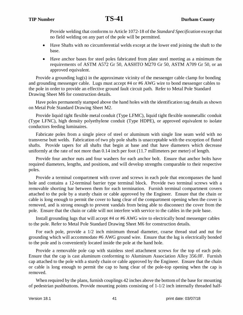
TIP Number TS-41 Durham County
Version 18.1 41 print date: 03/07/18
Provide welding that conforms to Article 1072-18 of the Standard Specification except that
no field welding on any part of the pole will be permitted.
· Have Shafts with no circumferential welds except at the lower end joining the shaft to the
base.
· Have anchor bases for steel poles fabricated from plate steel meeting as a minimum the
requirements of ASTM A572 Gr 50, AASHTO M270 Gr 50, ASTM A709 Gr 50, or an
approved equivalent.
Provide a grounding lug(s) in the approximate vicinity of the messenger cable clamp for bonding
and grounding messenger cable. Lugs must accept #4 or #6 AWG wire to bond messenger cables to
the pole in order to provide an effective ground fault circuit path. Refer to Metal Pole Standard
Drawing Sheet M6 for construction details.
Have poles permanently stamped above the hand holes with the identification tag details as shown
on Metal Pole Standard Drawing Sheet M2.
Provide liquid tight flexible metal conduit (Type LFMC), liquid tight flexible nonmetallic conduit
(Type LFNC), high density polyethylene conduit (Type HDPE), or approved equivalent to isolate
conductors feeding luminaires.
Fabricate poles from a single piece of steel or aluminum with single line seam weld with no
transverse butt welds. Fabrication of two ply pole shafts is unacceptable with the exception of fluted
shafts. Provide tapers for all shafts that begin at base and that have diameters which decrease
uniformly at the rate of not more than 0.14 inch per foot (11.7 millimeters per meter) of length.
Provide four anchor nuts and four washers for each anchor bolt. Ensure that anchor bolts have
required diameters, lengths, and positions, and will develop strengths comparable to their respective
poles.
Provide a terminal compartment with cover and screws in each pole that encompasses the hand
hole and contains a 12-terminal barrier type terminal block. Provide two terminal screws with a
removable shorting bar between them for each termination. Furnish terminal compartment covers
attached to the pole by a sturdy chain or cable approved by the Engineer. Ensure that the chain or
cable is long enough to permit the cover to hang clear of the compartment opening when the cover is
removed, and is strong enough to prevent vandals from being able to disconnect the cover from the
pole. Ensure that the chain or cable will not interfere with service to the cables in the pole base.
Install grounding lugs that will accept #4 or #6 AWG wire to electrically bond messenger cables
to the pole. Refer to Metal Pole Standard Drawing Sheet M6 for construction details.
For each pole, provide a 1/2 inch minimum thread diameter, coarse thread stud and nut for
grounding which will accommodate #6 AWG ground wire. Ensure that the lug is electrically bonded
to the pole and is conveniently located inside the pole at the hand hole.
Provide a removable pole cap with stainless steel attachment screws for the top of each pole.
Ensure that the cap is cast aluminum conforming to Aluminum Association Alloy 356.0F. Furnish
cap attached to the pole with a sturdy chain or cable approved by the Engineer. Ensure that the chain
or cable is long enough to permit the cap to hang clear of the pole-top opening when the cap is
removed.
When required by the plans, furnish couplings 42 inches above the bottom of the base for mounting
of pedestrian pushbuttons. Provide mounting points consisting of 1-1/2 inch internally threaded half-

TIP Number TS-42 Durham County
Version 18.1 42 print date: 03/07/18
couplings that comply with the NEC and that are mounted within the poles. Ensure that couplings are
essentially flush with the outside surfaces of the poles and are installed before any required
galvanizing. Provide a threaded plug in each mounting point. Ensure that the surface of the plug is
essentially flush with the outer end of the mounting point when installed and has a recessed hole to
accommodate a standard wrench.
4.3. STRAIN POLE SHAFTS
Provide 2 messenger cable (span wire) clamps and associated hardware for attachment of
messenger cable. Ensure that diameter of the clamp is appropriate to its location on the pole and is
appropriately designed to be adjustable from 1’-6” below the top, down to 6’-6” below the top of the
pole. Do not attach more than one support cable to a messenger cable clamp.
Provide a minimum of three (3) 2 inch (50 mm) holes equipped with an associated coupling and
weatherhead on the messenger cable load side of the pole to accommodate passage of signal cables
from inside the pole. Provide galvanized threaded plugs for all unused couplings at pole entrance
points. Refer to Metal Pole Standard Drawing Sheet M3 for fabrication details.
Ensure that allowable pole deflection does not exceed that allowed per 6th Edition AASHTO.
Ensure maximum deflection at the top of the pole does not exceed 2.5 percent of the pole height.
4.4. MAST ARM POLE SHAFTS
Ensure that allowable pole deflection does not exceed that allowed per 6th Edition AASHTO.
Ensure that maximum angular rotation of the top of the mast arm pole does not exceed 1 degree 40
minutes (1°40').
A. Construction Methods:
Install metal poles, hardware, and fittings as shown on the manufacturer’s installation drawings.
Install metal poles so that when the pole is fully loaded it is within 1 degree 40 minutes (1°40') of
vertical. Install poles with the manufacturer’s recommended “rake.” Use threaded leveling nuts to
establish rake if required.
4.5. MAST ARMS
Provide pole plates and associated gussets and fittings for attachment of required mast arms. As
part of each mast arm attachment, provide a cable passage hole in the pole to allow passage of signal
cables from the pole to the arm.
Ensure that allowable mast arm deflection does not exceed that allowed per 6th Edition AASHTO.
Also when arm is fully loaded, tip of the arm shall not go below the arm attachment point with the
pole for all load conditions per 6th Edition AASHTO.
Furnish all arm plates and necessary attachment hardware, including bolts and brackets.
Provide two extra bolts for each arm.
Provide grommet holes on the arms to accommodate cables for the signals.
Provide arms with weatherproof connections for attaching to the shaft of the pole.
Provide hardware that is galvanized steel, stainless steel, or corrosive-resistant aluminum.
Provide a removable end cap with stainless steel attachment screws for the end of each mast arm.
Ensure that the cap is cast aluminum conforming to Aluminum Association Alloy 356.0F. Furnish

TIP Number TS-43 Durham County
Version 18.1 43 print date: 03/07/18
cap attached to the arm with a sturdy chain or cable approved by the Engineer. Ensure that the chain
or cable is long enough to permit the cap to hang clear of the arm end opening when the cap is removed.
Comply with the following for Steel Luminaire Arms:
· In addition to tapered tube, luminaire arms may be standard weight black steel pipe
conforming to ASTM A 53-90a, Type E or Type S, Grade B or an approved equivalent.
· Conform to the welding requirements of the steel poles.
· After all fabricating, cutting, punching, and welding are completed, luminaire arms should be
hot-dipped galvanized inside and outside.
· In accordance with the National Electrical Code (NEC) Article 230.2(E), provide identification
of the electrical source provider for the luminaire feeder circuit with contact information on a
permanent label located in the pole hand hole in the vicinity of the feeder circuit raceway.
A. Materials:
After all fabricating, cutting, punching, and welding are completed, hot-dip galvanize the
structure in accordance with the AASHTO M 111 or an approved equivalent.
B. Construction Methods:
Install horizontal-type arms with sufficient manufactured rise to keep arm from deflecting below
the arm attachment height.
Attach cap to the mast arm with a sturdy chain or cable. Ensure that the chain or cable is long
enough to permit the cap to hang clear of the arm opening when the cap is removed.
For mast arm poles, use full penetration welds with back-up ring at the pole base and at the arm
base connection.
4.6. DRILLED PIER FOUNDATIONS FOR METAL TRAFFIC SIGNAL POLES
Analysis procedures and formulas shall be based on AASHTO 6th Edition, latest ACI code and
the Drilled Shafts: Construction Procedures and Design Methods FHWA-NHI-10-016 manual.
Design methods based on engineering publications or research papers needs to have prior approval
from NCDOT. The Department reserves the right to accept or disapprove any method used for the
analysis.
Use a Factor of Safety of 1.33 for torsion and 2.0 for bending for the foundation design.
Foundation design for lateral load shall not exceed 1” lateral deflection at top of foundation.
For lateral analysis, use LPILE Plus V6.0 or later. Inputs, results and corresponding graphs are to
be submitted with the design calculations.
Skin Friction is to be calculated using the α-method for cohesive soils and the β-method for
cohesion-less soils (Broms method will not be accepted). Detailed descriptions of the “α” and
“β” methods can be found in FHWA-NHI-10-016.
Omit first 2.5ft for cohesive soils when calculating skin friction.
When hammer efficiency is not provided, assume a value of 0.70.

TIP Number TS-44 Durham County
Version 18.1 44 print date: 03/07/18
Design all custom foundations to carry the maximum capacity of each metal pole. For standard
case strain poles only, if a custom foundation is designed, use the actual shear, axial and moment
reactions from the Standard Foundation Selection Table shown on Standard Drawing No. M8.
When poor soil conditions are encountered which could create an excessively large foundation
design, consideration may be given to allowing an exemption to the maximum capacity design. The
contractor must gain approval from the engineer before reducing a foundation’s capacity. On
projects where poor soil is known to be present, it is advisable that the contractor consider getting
foundations approved before releasing poles for fabrication.
Have the contractor notify the engineer if the proposed foundation is to be installed on a slope
other than 8H: 1V or flatter.
A. Description:
Furnish and install foundations for NCDOT metal poles with all necessary hardware in
accordance with the plans and specifications.
Metal Pole Standards have been developed and implemented by NCDOT for use at signalized
intersections in North Carolina. If the plans call for a standard pole, then a standard foundation may
be selected from the plans. However, the Contractor is not required to use a standard foundation. If
the Contractor chooses to design a non-standard site-specific foundation for a standard pole or if the
plans call for a non-standard site-specific pole, design the foundation to conform to the applicable
provisions in the NCDOT Metal Pole Standard Drawings and Section B7 (Non-Standard Foundation
Design) below. If non-standard site specific foundations are designed for standard QPL approved
strain poles, the foundation designer must use the design moment specified by load case on Metal
Pole Standard Drawing Sheet M8. Failure to conform to this requirement will be grounds for
rejection of the design.
If the Contractor chooses to design a non-standard foundation for a standard pole and the soil test
results indicate a standard foundation is feasible for the site, the Contractor will be paid the cost of
the standard foundation (drilled pier and wing wall, if applicable). Any additional costs associated
with a non-standard site-specific foundation including additional materials, labor and equipment will
be considered incidental to the cost of the standard foundation. All costs for the non-standard
foundation design will also be considered incidental to the cost of the standard foundation.
B. Soil Test and Foundation Determination:
1. General:
Drilled piers are reinforced concrete sections, cast-in-place against in situ, undisturbed material.
Drilled piers are of straight shaft type and vertical.
Some standard drilled piers for supporting poles with mast arms may require wing walls to resist
torsional rotation. Based upon this provision and the results of the required soil test, a drilled pier
length and wing wall requirement may be determined and constructed in accordance with the plans.
For non-standard site-specific poles, the contractor-selected pole fabricator will determine if the
addition of wing walls is necessary for the supporting foundations.
2. Soil Test:
Perform a soil test at each proposed metal pole location. Complete all required fill placement
and excavation at each signal pole location to finished grade before drilling each boring. Soil tests

TIP Number TS-45 Durham County
Version 18.1 45 print date: 03/07/18
performed that are not in compliance with this requirement may be rejected and will not be paid.
Drill one boring to a depth of 26 feet within a 25 foot radius of each proposed foundation.
Perform standard penetration tests (SPT) in accordance with ASTM D 1586 at depths of 1, 2.5,
5, 7.5, 10, 15, 20 and 26 feet. Discontinue the boring if one of the following occurs:
· A total of 100 blows have been applied in any 2 consecutive 6-in. intervals.
· A total of 50 blows have been applied with < 3-in. penetration.
Describe each intersection as the “Intersection of (Route or SR #), (Street Name) and (Route or
SR #), (Street Name), ________ County, Signal Inventory No. _____”. Label borings with “B- N, S,
E, W, NE, NW, SE or SW” corresponding to the quadrant location within the intersection. Pole
numbers should be made available to the Drill Contractor. Include pole numbers in the boring label
if they are available. If they are not available, ensure the boring labels can be cross-referenced to
corresponding pole numbers. For each boring, submit a legible (hand written or typed) boring log
signed and sealed by a licensed Geologist or Professional Engineer registered in North Carolina.
Include on each boring the SPT blow counts and N-values at each depth, depth of the boring,
hammer efficiency, depth of water table and a general description of the soil types encountered using
the AASHTO Classification System.
3. Standard Foundation Determination:
Use the following method for determining the Design N-value:
NAVG = (N@1’ + [email protected]’ +……... N@Deepest Boring Depth)
Total Number of N-values
Y = (N@1’)2 + ([email protected]’)2 + ……... (N@Deepest Boring Depth)2
Z = (N@1’ + [email protected]’ +……... N@Deepest Boring Depth)
NSTD DEV = (Total Number of N-values x Y) – Z2 0.5
(Total Number of N-values) x (Total Number of N-values – 1)
Design N-value equals lesser of the following two conditions:
NAVG – (NSTD DEV x 0.45)
Or
Average of First Four N-Values = (N@1’ + [email protected]’ + N@5’ + [email protected]’)
4
Note: If less than 4 N-values are obtained because of criteria listed in Section 2 above, use
average of N-values collected for second condition. Do not include the N-value at the
deepest boring depth for above calculations if the boring is discontinued at or before
the required boring depth because of criteria listed in Section 2 above. Use N-value of

TIP Number TS-46 Durham County
Version 18.1 46 print date: 03/07/18
zero for weight of hammer or weight of rod. If N-value is greater than 50, reduce N-
value to 50 for calculations.
If standard NCDOT strain poles are shown on the plans and the Contractor chooses to use
standard foundations, determine a drilled pier length, “L,” for each signal pole from the Standard
Foundations Chart (sheet M 8) based on the Design N-value and the predominant soil type. For each
standard pole location, submit a completed “Metal Pole Standard Foundation Selection Form”
signed by the Contractor’s representative. Signature on form is for verification purposes only.
Include the Design N-value calculation and resulting drilled pier length, “L,” on each form.
If non-standard site-specific poles are shown on the plans, submit completed boring logs
collected in accordance with Section 2 (Soil Test) above along with pole loading diagrams from the
plans to the contractor-selected pole fabricator to assist in the pole and foundation design.
If one of the following occurs, the Standard Foundations Chart shown on the plans may not be
used and a non-standard foundation may be required. In such case, contact the Engineer.
· The Design N-value is less than 4.
· The drilled pier length, “L”, determined from the Standard Foundations Chart, is greater than
the depth of the corresponding boring.
In the case where a standard foundation cannot be used, the Department will be responsible for the
additional cost of the non-standard foundation.
Foundation designs are based on level ground around the traffic signal pole. If the slope around
the edge of the drilled pier is steeper than 8:1 (H:V) or the proposed foundation will be less than 10
feet from the top of an embankment slope, the Contractor is responsible for providing slope
information to the foundation designer and to the Engineer so it can be considered in the design.
The “Metal Pole Standard Foundation Selection Form” may be found at:
http://www.ncdot.gov/doh/preconstruct/highway/geotech/formdet/misc/MetalPole.pdf
If assistance is needed, contact the Engineer.
4. Non-Standard Foundation Design:
Design non-standard foundations based upon site-specific soil test information collected in
accordance with Section 2 (Soil Test) above. Design drilled piers for side resistance only in
accordance with Section 4.6 of the AASHTO Standard Specifications for Highway Bridges. Use the
computer software LPILE version 6.0 or later manufactured by Ensoft, Inc. to analyze drilled piers.
Use the computer software gINT V8i or later manufactured by Bentley Systems, Inc. with the
current NCDOT gINT library and data template to produce SPT boring logs. Provide a drilled pier
foundation for each pole with a length and diameter that result in a horizontal lateral movement of
less than 1 inch at the top of the pier and a horizontal rotational movement of less than 1 inch at the
edge of the pier. Contact the Engineer for pole loading diagrams for standard poles to be used for
non-standard foundation designs. Submit any non-standard foundation designs including drawings,
calculations, and soil boring logs to the Engineer for review and approval before construction.
C. Drilled Pier Construction:
Construct drilled pier foundations in accordance with the Foundations and Anchor Rod
Assemblies for Metal Poles provision.

TIP Number TS-47 Durham County
Version 18.1 47 print date: 03/07/18
4.7. CUSTOM DESIGN OF TRAFFIC SIGNAL SUPPORTS
A. General:
Design traffic signal supports with foundations consisting of metal strain poles or metal poles
with mast arms.
The lengths of the metal signal poles shown on the plans are estimated from available data for
bid purposes. Determine the actual length of each pole from field measurements and adjusted cross-
sections. Furnish the revised pole heights to the Engineer. Use all other dimensional requirements
shown on the plans.
Ensure each pole includes an identification tag with information and location positions as
defined on Metal Pole Standard Drawing Sheets M2, M3 and M4. All pole shaft tags must include
the NCDOT Inventory number followed by the pole number shown on the traffic signal or ITS (non-
signalized locations) plan.
Design all traffic signal support structures using the following 6th Edition AASHTO specifications:
· Design for a 50 year service life as recommended by Table 3.8.3-2.
· Use the wind pressure map developed from 3-second gust speeds, as provided in Article 3.8.
· Ensure signal support structures include natural wind gust loading and truck-induced gust
loading in the fatigue design, as provided for in Articles 11.7.1.2 and 11.7.1.3, respectively.
Designs need not consider periodic galloping forces.
· Assume the natural wind gust speed in North Carolina is 11.2 mph. For natural wind fatigue
stress calculations, utilize a drag coefficient (Cd) computed for 11.2 mph wind velocity and
not the basic wind speed velocity.
· Design for Category II fatigue, as provided for in Article 11.6, unless otherwise specified.
· Calculate all stresses using applicable equations from Section 5. The Maximum allowable
stress ratios for all signal support designs are 0.9.
· Conform to article 10.4.2 and 11.8 for all deflection requirements.
Ensure that the design permits cables to be installed inside poles and mast arms.
Unless otherwise specified by special loading criteria, the computed surface area for ice load on
signal heads is:
· 3-section, 12-inch, Surface area: 26.0 ft2 (17.0 ft2 without back plate)
· 4-section, 12-inch, Surface area: 32.0 ft2 (21.0 ft2 without back plate)
· 5-section, 12-inch, Surface area: 42.0 ft2 (29.0 ft2 without back plate)
The ice loading for signal heads defined above includes the additional surface area that back
plates will induce. Special loading criteria may be specified in instances where back plates will not
be installed on signal heads. Refer to the Loading Schedule on each Metal Pole Loading Diagram for
revised signal head surface areas. The pole designer should revise ice loads accordingly in this
instance. Careful examination of the plans when this is specified is important as this may impact
sizing of the metal support structure and foundation design which could affect proposed bid quotes.
All maximum stress ratios of 0.9 still apply.

TIP Number TS-48 Durham County
Version 18.1 48 print date: 03/07/18
Assume the combined minimum weight of a messenger cable bundle (including messenger
cable, signal cable and detector lead-in cables) is 1.3 lbs/ft. Assume the combined minimum
diameter of this cable bundle is 1.3 inches.
Ensure that designs provide a removable pole cap with stainless steel attachment screws for each
pole top and mast arm end.
B. Metal Poles:
Submit design drawings for approval including pre-approved QPL pole drawings. Show all the
necessary details and calculations for the metal poles including the foundation and connections.
Include NCDOT inventory number on design drawings. Include as part of the design calculations the
ASTM specification numbers for the materials to be used. Provide the types and sizes of welds on
the design drawings. Include a Bill of Materials on design drawings. Ensure design drawings and
calculations are signed, dated, and sealed by the responsible professional engineer licensed in the
state of North Carolina. Immediately bring to the attention of the Engineer any structural deficiency
that becomes apparent in any assembly or member of any assembly as a result of the design
requirements imposed by these specifications, the plans, or the typical drawings. Said Professional
Engineer is wholly responsible for the design of all poles and arms. Review and acceptance of these
designs by the Department does not relieve the said Professional Engineer of his responsibility. Do
not fabricate the assemblies until receipt of the Department’s approval of the design drawings.
For mast arm poles, provide designs with provisions for pole plates and associated gussets and
fittings for mast arm attachment. As part of each mast arm attachment, provide a grommeted 2”
diameter hole on the shaft side of the connection to allow passage of the signal cables from the pole
to the arm.
Where ice is present, assume wind loads as shown in Figure 3.9.4.2-3 of the 6th Edition
AASHTO Specification for Group III loading.
For each strain pole, provide two messenger cable clamps and associated hardware to attach the
messenger support cable. Ensure that the diameter of the clamps is appropriately designed to be
adjustable from 1’-6” inches below the top, down to 6’-6” below the top of the pole. Do not attach
more than one messenger support cable to a messenger cable clamp.
Provide a grounding lug(s) in the approximate vicinity of the messenger cable clamp for bonding
and grounding messenger cable. Lugs must accept #4 or #6 AWG wire to bond messenger cables to
the pole in order to provide an effective ground fault circuit path. Refer to Metal Pole Standard
Drawing Sheet M6 for construction details.
Design tapers for all pole shafts that begin at the base with diameters that decrease uniformly at
the rate of 0.14 inch per foot of length.
Design a base plate on each pole. The minimum base plate thickness for all poles is determined
by the following criteria:
Case 1 Circular or rectangular solid base plate with the upright pole welded to the top surface of
base plate with full penetration butt weld, and where no stiffeners are provided. A base plate with
a small center hole, which is less than 1/3 of the upright diameter, and located concentrically
with the upright pole, may be considered as a solid base plate.
The magnitude of bending moment in the base plate, induced by the anchoring force of each
anchor bolt is M = (P x D1) / 2, where

TIP Number TS-49 Durham County
Version 18.1 49 print date: 03/07/18
M = bending moment at the critical section of the base plate induced by one anchor bolt
P = anchoring force of each anchor bolt
D1 = horizontal distance between the anchor bolt center and the outer face of the upright,
or the difference between the bolt circle radius and the outside radius of the upright
Locate the critical section at the face of the anchor bolt and perpendicular to the bolt circle
radius. The overlapped part of two adjacent critical sections is considered ineffective.
Case 2 Circular or rectangular base plate with the upright pole socketed into and attached to the
base plate with two lines of fillet weld, and where no stiffeners are provided, or any base plate
with a center hole that is larger in diameter than 1/3 of the upright diameter.
The magnitude of bending moment induced by the anchoring force of each anchor bolt is M = P
x D2,
where P = anchoring force of each anchor bolt
D2 = horizontal distance between the face of the upright and the face of the anchor bolt
nut
Locate the critical section at the face of the anchor bolt top nut and perpendicular to the radius of
the bolt circle. The overlapped part of two adjacent critical sections is considered ineffective.
If the base plate thickness calculated for Case 2 is less than Case 1, use the thickness calculated
for Case 1.
The following additional owner requirements apply concerning pole base plates.
· Ensure that whichever case governs as defined above, the anchor bolt diameter is set to
match the base plate thickness. If the minimum diameter required for the anchor bolt exceeds
the thickness required for the base plate, set the base plate thickness equal to the required bolt
diameter.
· For dual mast arm supports, or for single mast arm supports 50’ or greater, use a minimum 8
bolt orientation with 2” diameter anchor bolts, and a 2” thick base plate.
· For all metal poles with mast arms, use a full penetration groove weld with a backing ring to
connect the pole upright component to the base. Refer to Metal Pole Standard Drawing Sheet
M4.
Ensure that designs have anchor bolt holes with a diameter 1/4 inch larger than the anchor
bolt diameters in the base plate.
Ensure that the anchor bolts have the required diameters, lengths, and positions, and will develop
strengths comparable to their respective poles.
Provide designs with a 6 x 12-inch hand hole with a reinforcing frame for each pole.
Provide designs with a terminal compartment with cover and screws in each pole that
encompasses the hand hole and contains provisions for a 12-terminal barrier type terminal block.
For each pole, provide designs with provisions for a 1/2 inch minimum thread diameter, coarse
thread stud and nut for grounding which will accommodate a #6 AWG ground wire. Ensure the lug
is electrically bonded to the pole and is conveniently located inside the pole at the hand hole.

TIP Number TS-50 Durham County
Version 18.1 50 print date: 03/07/18
When required, design couplings on the pole for mounting pedestrian pushbuttons at a height of
42 inches above the bottom of the base. Provide mounting points consisting of 1-1/2 inch internally
threaded half-couplings that comply with the NEC that are mounted within the poles. Ensure the
couplings are essentially flush with the outside surfaces of the poles and are installed before any
required galvanizing. Provide a threaded plug for each half coupling. Ensure that the surface of the
plug is essentially flush with the outer end of the mounting point when installed and has a recessed
hole to accommodate a standard wrench.
C. Mast Arms:
Design all arm plates and necessary attachment hardware, including bolts and brackets as
required by the plans.
Design for grommeted holes on the arms to accommodate the cables for the signals if specified.
Design arms with weatherproof connections for attaching to the shaft of the pole.
Always use a full penetration groove weld with a backing ring to connect the mast arm to the
pole. Refer to Metal Pole Standard Drawing Sheet M5.
Capacity of tapped flange plate must be sufficient to develop the full capacity of the connecting
bolts. In all cases the flange plate of both arm and shaft must be at least as thick as the arm
connecting bolts are in diameter.
4.8. METAL SIGNAL POLE REMOVALS
A. Description:
Remove and dispose of existing metal signal poles including mast arms, and remove and dispose
of existing foundations, associated anchor bolts, electrical wires and connections.
B. Construction Methods:
1. Foundations:
Remove and promptly dispose of the metal signal pole foundations including reinforcing steel,
electrical wires, and anchor bolts to a minimum depth of two feet below the finished ground
elevation. At the Contractor’s option, remove the complete foundation.
2. Metal Poles:
Assume ownership of the metal signal poles, remove the metal signal poles, and promptly
transport the metal signal poles from the project. Use methods to remove the metal signal poles and
attached traffic signal equipment that will not result in damage to other portions of the project or
facility. Repair damages that are a result of the Contractor's actions at no additional cost to the
Department.
Transport and properly dispose of the materials.
Backfill and compact disturbed areas to match the finished ground elevation. Seed unpaved
areas.
Use methods to remove the foundations that will not result in damage to other portions of the
project or facility. Repair damages that are a result of the Contractor's actions at no cost to the
Department.

TIP Number TS-51 Durham County
Version 18.1 51 print date: 03/07/18
4.9. POLE NUMBERING SYSTEM
A. New Poles
Attach an identification tag to each pole shaft and mast arm section as shown on Metal Pole
Standard Drawing Sheet M2 “Typical Fabrication Details Common To All Metal Poles”.
B. Reused Poles
Do not remove the original identification tag(s) from the pole shaft and/or mast arm sections.
Add a new identification tag based on the new location for any reused poles and/or mast
arms.
4.10. REUSED POLE SHAFTS AND/OR MAST ARMS
Provide shop drawings along with new foundation designs for review and approval prior to
furnishing and/or installing any reused metal poles and/or mast arms. Use the same requirements as
specified for new materials as stated above in these Special Provisions.
For reused pole shaft and mast arm combinations, it is preferable to use the original shafts and arms
that were used together at the time of original installation.
4.11. MEASUREMENT AND PAYMENT
Actual number of metal strain signal poles (without regard to height or load capacity) furnished,
installed and accepted.
Actual number of metal poles with single mast arms furnished, installed, and accepted.
Actual number of metal poles with dual mast arms furnished, installed, and accepted.
Actual number of reused metal strain signal poles (without regard to height or load capacity)
furnished, installed and accepted.
Actual number of reused metal strain signal poles (without regard to height or load capacity)
installed and accepted.
Actual number of reused metal poles with single mast arms furnished, installed, and accepted.
Actual number of reused metal poles with single mast arms installed and accepted.
Actual number of reused metal poles with dual mast arms furnished, installed, and accepted.
Actual number of reused metal poles with dual mast arms installed and accepted.
Actual number of soil tests with SPT borings drilled furnished and accepted.
Actual volume of concrete poured in cubic yards of drilled pier foundation furnished, installed
and accepted.
Actual number of foundations with wing walls furnished, installed and accepted, excluding
foundation length. Refer to method of measurement above for drilled pier foundation.
Actual number of designs for metal strain poles furnished and accepted.
Actual number of designs for mast arms with metal poles furnished and accepted.
Actual number of metal signal pole foundations removed and disposed.
Actual number of metal signal poles removed and disposed.

TIP Number TS-52 Durham County
Version 18.1 52 print date: 03/07/18
No measurement will be made for foundation designs prepared with metal pole designs, as these
will be considered incidental to designing signal support structures.
Payment will be made under:
Metal Strain Signal Pole ............................................................................................................. Each
Metal Pole with Single Mast Arm .............................................................................................. Each
Metal Pole with Dual Mast Arm ................................................................................................. Each
Furnish and Install Reused Metal Strain Signal Pole ................................................................... Each
Install Reused Metal Strain Signal Pole ...................................................................................... Each
Furnish and Install Reused Metal Pole with Single Mast Arm .................................................... Each
Install Reused Metal Pole with Single Mast Arm ........................................................................ Each
Furnish and Install Reused Metal Pole with Dual Mast Arm ....................................................... Each
Install Reused Metal Pole with Dual Mast Arm .......................................................................... Each
Soil Test ..................................................................................................................................... Each
Drilled Pier Foundation .................................................................................................... Cubic Yard
Foundation with Wing Walls (______) ....................................................................................... Each
Metal Strain Pole Design ............................................................................................................ Each
Mast Arm with Metal Pole Design ............................................................................................. Each
Metal Pole Foundation Removal ................................................................................................ Each
Metal Pole Removal ................................................................................................................... Each

TIP Number TS-53 Durham County
Version 18.1 53 print date: 03/07/18
5. BACK PULL FIBER OPTIC CABLE
5.1. DESCRIPTION
Back pull and store or back pull and reinstall existing communications cable.
5.2. CONSTRUCTION
During project construction where instructed to back pull existing aerial sections of fiber optic
communications cable, de-lash the cable from the messenger cable and back pull the cable to a point
where it can be stored or re-routed as shown on the plans. If instructed, remove and discard the
existing messenger cable and pole mounting hardware once the cable is safely out of harm’s way.
During project construction where instructed to back pull existing underground sections of fiber
optic communications cable, back pull the cable to a point where it can be stored or re-routed as
shown on the plans. If instructed, remove abandoned junction boxes and backfill with a suitable
material to match the existing grade. Leave abandoned conduits in place unless otherwise noted.
Where instructed, re-pull the fiber optic cable back along messenger cable or through conduit
systems.
5.3. MEASUREMENT AND PAYMENT
Back Pull Fiber Optic Cable will be paid for as the actual linear feet of fiber optic cable back
pulled and either stored or back pulled and rerouted. Payment is for the actual linear feet of cable
back pulled.
No payment will be made for removing messenger cable and pole mounting hardware or
removing junction boxes and back filling to match the surrounding grade as these items of work will
be considered incidental to back pulling the fiber optic cable.
Payment will be made under:
Back Pull Fiber Optic Cable .................................................................................. Linear Feet
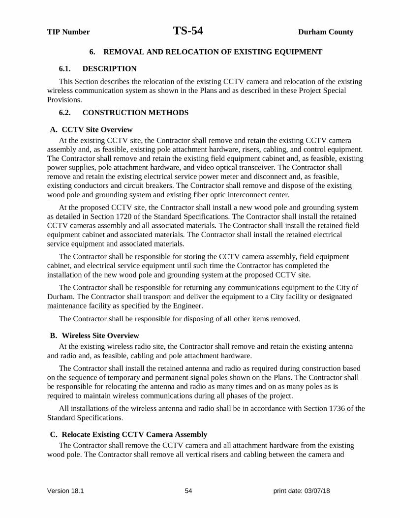
TIP Number TS-54 Durham County
Version 18.1 54 print date: 03/07/18
6. REMOVAL AND RELOCATION OF EXISTING EQUIPMENT
6.1. DESCRIPTION
This Section describes the relocation of the existing CCTV camera and relocation of the existing
wireless communication system as shown in the Plans and as described in these Project Special
Provisions.
6.2. CONSTRUCTION METHODS
A. CCTV Site Overview
At the existing CCTV site, the Contractor shall remove and retain the existing CCTV camera
assembly and, as feasible, existing pole attachment hardware, risers, cabling, and control equipment.
The Contractor shall remove and retain the existing field equipment cabinet and, as feasible, existing
power supplies, pole attachment hardware, and video optical transceiver. The Contractor shall
remove and retain the existing electrical service power meter and disconnect and, as feasible,
existing conductors and circuit breakers. The Contractor shall remove and dispose of the existing
wood pole and grounding system and existing fiber optic interconnect center.
At the proposed CCTV site, the Contractor shall install a new wood pole and grounding system
as detailed in Section 1720 of the Standard Specifications. The Contractor shall install the retained
CCTV cameras assembly and all associated materials. The Contractor shall install the retained field
equipment cabinet and associated materials. The Contractor shall install the retained electrical
service equipment and associated materials.
The Contractor shall be responsible for storing the CCTV camera assembly, field equipment
cabinet, and electrical service equipment until such time the Contractor has completed the
installation of the new wood pole and grounding system at the proposed CCTV site.
The Contractor shall be responsible for returning any communications equipment to the City of
Durham. The Contractor shall transport and deliver the equipment to a City facility or designated
maintenance facility as specified by the Engineer.
The Contractor shall be responsible for disposing of all other items removed.
B. Wireless Site Overview
At the existing wireless radio site, the Contractor shall remove and retain the existing antenna
and radio and, as feasible, cabling and pole attachment hardware.
The Contractor shall install the retained antenna and radio as required during construction based
on the sequence of temporary and permanent signal poles shown on the Plans. The Contractor shall
be responsible for relocating the antenna and radio as many times and on as many poles as is
required to maintain wireless communications during all phases of the project.
All installations of the wireless antenna and radio shall be in accordance with Section 1736 of the
Standard Specifications.
C. Relocate Existing CCTV Camera Assembly
The Contractor shall remove the CCTV camera and all attachment hardware from the existing
wood pole. The Contractor shall remove all vertical risers and cabling between the camera and

TIP Number TS-55 Durham County
Version 18.1 55 print date: 03/07/18
equipment cabinet that is attached to the wood pole. Exercise care not to damage the cabling or any
entrance holes in the equipment cabinet.
Furnish all tools, equipment, materials, supplies, and hardware necessary to install a fully
operational CCTV camera system as depicted in the Plans.
Mount CCTV camera units at a height sufficient to adequately see traffic in all directions and as
approved by the Engineer. The maximum attachment height is 45 feet above ground level.
Mount the CCTV camera units such that a minimum 5 feet of clearance is maintained between the
camera and the top of the pole.
Obtain approval of the camera locations and orientation from the Engineer prior to installing the
CCTV camera assemblies.
Mount CCTV cameras on the side of poles nearest intended field of view. Avoid occluding the
view with the pole.
Ground all equipment as called for in the Standard Specifications, these Special Provisions, and
the Plans.
Install surge protectors on all ungrounded conductors entering the CCTV enclosure. House the
protectors in a small, ventilated weatherproof cabinet attached near the CCTV attachment point in a
manner approved by the Engineer.
D. Relocate Existing Field Equipment Cabinet
The Contractor shall remove the field equipment cabinet and all attachment hardware from the
existing wood pole. The Contractor shall remove all risers, conduits, conductors, and cabling
between the equipment cabinet and electrical service. Exercise care not to damage the cabling or any
entrance holes in the equipment cabinet.
Use stainless steel banding or other method approved by the Engineer to fasten cabinet to pole.
Install field equipment cabinet so that the height to the middle of the enclosure is 4 feet from ground
level. No risers shall enter the top or sides of the equipment cabinet.
Install all new conduits, condulets, and attachments to equipment cabinets in a manner that
preserves the minimum bending radius of cables and creates water proof connections and seals.
Install surge protection in the cabinet to protect the CCTV and communications equipment from
electrical surges.
E. Relocate Existing Communications Equipment
The Contractor shall remove the fiber optic interconnect center and fiber optic video transceiver
from the existing field equipment cabinet. Exercise care not to damage the transceiver.
The Contractor shall dispose of the existing interconnect center and install a new interconnect
center at the new CCTV site as shown in the Plans.
Install and fully integrate the fiber optic video transceiver in the CCTV cabinets in the field as
shown in the Plans. Furnish and install all cables needed to integrate the transceiver with the CCTV
camera assembly and fiber optic interconnect center.

TIP Number TS-56 Durham County
Version 18.1 56 print date: 03/07/18
F. Relocate Existing Electrical Service
Coordinate with the Engineer and the utility company to de-energize the existing service prior to
working at the existing CCTV site.
The Contractor shall remove and retain the electrical service associated with the existing CCTV
site. The Contractor shall remove and retain the existing meter base and disconnect on the wood
pole. The Contractor shall remove and retain all feeder conductors, risers, and any other material
between the electrical service and equipment cabinet.
Install the electrical service meter and disconnect on the new CCTV pole. Install grounding
system as required. Install riser and conductors required to integrate the electrical service with the
utility company and with the equipment cabinet. Perform all work in accordance with the Standard
Specifications.
G. Remove Existing Wood Pole
The Contractor shall remove and dispose of the existing wood pole after the removal of all other
materials.
Backfill all disturbed earth and perform surface restoration as required by the Standard
Specifications.
H. Relocate Existing Wireless Radio Equipment
The Contractor shall remove the existing wireless radio and associated antenna as shown on the
Plans.
Install the wireless radio equipment in accordance with Section 1736 of the Standard
Specifications. Prior to each installation of the antenna, a new radio path site survey shall be
performed according to Section 1736 of the Standard Specifications to confirm that communications
with other radios will remain fully functioning.
6.3. MEASUREMENT AND PAYMENT
Relocate Existing CCTV Camera Assembly will be measured and paid as the actual number of
CCTV and related equipment removed, retained, installed, and accepted in accordance with these
Project Special Provisions. No separate measurement will be made for materials that are damaged
during removal or materials that are not able to be reused including cables, connectors, CCTV camera
attachment assemblies, risers, conduit, condulets, grounding equipment, surge protectors, coaxial
cable, or any other equipment or labor required to install a fully functioning CCTV assembly. Removal
and disposal of any materials will be considered incidental. Storage, cost of transportation, tools,
materials, all related testing, cost of labor, incidentals and all other equipment necessary to remove the
existing materials will be considered incidental.
Relocate Existing Field Equipment Cabinet will be measured and paid as the actual number of
field equipment cabinets removed, retained, installed, and accepted in accordance with these Project
Special Provisions. No separate measurement will be made for materials that are damaged during
removal or materials that are not able to be reused including cabling, connectors, cabinet attachment
assemblies, conduit, condulets, risers, grounding equipment, surge protectors, or any other equipment
or labor required to install a fully functioning equipment cabinet. Removal and disposal of any
materials will be considered incidental. Storage, cost of transportation, tools, materials, all related
testing, cost of labor, incidentals and all other equipment necessary to remove the existing materials
will be considered incidental.

TIP Number TS-57 Durham County
Version 18.1 57 print date: 03/07/18
Relocate Existing Communications Equipment will be measured and paid as the actual number of
fiber optic video transceivers and related equipment removed, retained, installed, and accepted in
accordance with these Project Special Provisions. No separate measurement will be made for
materials that are damaged during removal or materials that are not able to be reused including cables,
or any other equipment or labor required to establish communications. Removal and disposal of any
materials will be considered incidental. Storage, cost of transportation, tools, materials, all related
testing, cost of labor, incidentals and all other equipment necessary to remove the existing materials
will be considered incidental.
Relocate Existing Electrical Service will be measured and paid as the actual number of electrical
service related equipment removed, retained, installed, and accepted in accordance with these Project
Special Provisions. No separate measurement will be made for materials that are damaged during
removal or materials that are not able to be reused including meters, disconnects, breakers, vertical
conduit, ground rods, ground wire, feeder conductors, or any other equipment or labor required to
install a fully functioning electrical service. Removal and disposal of any materials will be considered
incidental. Storage, cost of transportation, tools, materials, all related testing, cost of labor, incidentals
and all other equipment necessary to remove the existing materials will be considered incidental.
Remove Existing Wood Pole will be measured and paid as the actual number of wood poles
removed and accepted in accordance with these Project Special Provisions. Removal and disposal of
any materials will be considered incidental.
Relocate Existing Wireless Radio Equipment will be measured and paid as the actual number of
wireless antenna and radios and related equipment removed, retained, installed, and accepted in
accordance with these Project Special Provisions. No separate measurement will be made for any
temporary relocations made between the time the equipment is removed from the current location and
installed at the final location shown in the Plans. No separate measurement will be made for materials
that are damaged during removal or materials that are not able to be reused including antenna(s), radio,
power supplies, disconnect/snap switch, signs, decals, data interface cable/serial cable, coaxial cable,
lightning arrestor, radio frequency signal jumper, coaxial cable power divider (splitter), coaxial cable
connectors, coaxial cable shield grounding system with weatherproofing, labeling, or any other
equipment or labor required to install a fully functioning wireless radio system. Removal and disposal
of any materials will be considered incidental. Storage, cost of transportation, tools, materials, all
related testing, cost of labor, incidentals and all other equipment necessary to remove the existing
materials will be considered incidental.
Measurement and payment for furnishing and installing a new fiber optic interconnect center will
be made according to Section 1731 of the Standard Specifications.
Measurement and payment for furnishing and installing a new wood pole will be made according
to Section 1720 of the Standard Specifications.
Payment will be made under:
Pay Item Pay Unit
Relocate Existing CCTV Camera Assembly ..................................................................................Each
Relocate Existing Field Equipment Cabinet ...................................................................................Each
Relocate Existing Communications Equipment ..............................................................................Each
Relocate Existing Electrical Service...............................................................................................Each

TIP Number TS-58 Durham County
Version 18.1 58 print date: 03/07/18
Remove Existing Wood Pole .........................................................................................................Each
Relocate Existing Wireless Radio Equipment ................................................................................Each
7. CCTV EQUIPMENT
7.1. DESCRIPTION
Furnish and install CCTV equipment described in these Project Special Provisions. Furnish
equipment that is compatible, interoperable, and completely interchangeable with existing camera
equipment currently in use by the City of Durham. Ensure that the equipment is fully compatible with
all features of the existing video management software currently in use by the City of Durham.
Contact the City of Durham Traffic Engineer to confirm all CCTV locations prior to beginning
construction.
7.2. MATERIAL
A. General
Furnish and install new CCTV camera assemblies at the locations shown on the Plans. Each
assembly consists of the following:
· One Dome CCTV camera that contains in a single enclosed unit the following
functionality and accessories:
1. CCTV color digital signal processing camera unit with zoom lens, filter, control
circuit, and accessories
2. Motorized pan, tilt, and zoom
3. Pole-mount camera attachment assembly
4. All necessary cable, connectors and incidental hardware to make a complete and
operable system
· A lightning arrestor installed in-line between the CCTV camera and the
equipment cabinet components.
· A NEMA Type 4 enclosure constructed of aluminum with a clear acrylic
dome or approved equal Camera Unit housing.
B. Camera and Lens
1. Cameras
Furnish new charged-coupled device (CCD) color cameras. Furnish cameras with automatic gain
control (AGC) for clear images in varying light levels. The camera must meet the following minimum
requirements:
· Video signal format: NTSC composite color video output, 1 volt peak to peak
· Automatic Gain Control (AGC): 0-20 dB, peak-average adjustable
· Automatic focus: Automatic with manual override
· White balance: Automatic through the lens with manual override
· Electronic-Shutter: dip-switch selectable electronic shutter with speed range from
1/60 of a second (off) to 1/30,000th of a second
· Overexposure protection: The camera must have built-in circuitry or a protection
device to prevent any damage to the camera when pointed at strong light sources,
including the sun

TIP Number TS-59 Durham County
Version 18.1 59 print date: 03/07/18
· Sensitivity: 1.5 lux at 90% scene reflectance
· Signal to noise ratio: Greater than 48-dB
· Video output Connection: 1-volt peak to peak, 75 ohms terminated, BNC connector
· Power: 24 VAC or less
2. Zoom Lens
Furnish each camera with a motorized zoom lens that is high performance integrated dome
system or approved equivalent with automatic iris control with manual override and neutral density
spot filter. Furnish lenses that meet the following optical specifications:
· Focal length: 0.16” – 3.45”, 35X optical zoom, and 12X electronic zoom
· Preset positioning: 64 Presets
The lens must be capable of both automatic and remote manual control iris and focus override
operation. The lens must be equipped for remote control of zoom and focus, including automatic
movement to any of the preset zoom and focus positions. Mechanical or electrical means must be
provided to protect the motors from overrunning in extreme positions. The operating voltages of the
lens must be compatible with the outputs of the camera control.
3. Camera Housing
Furnish new dome style enclosure for the CCTV assemblies. Equip each housing with mounting
assembly for attachment to the CCTV camera pole. The enclosures must be equipped with a
sunshield and be fabricated from corrosion resistant aluminum and finished in a neutral color of
weather resistant enamel. The enclosure must meet or exceed NEMA 4X ratings. The viewing area
of the enclosure must be tempered glass.
4. Pan and Tilt Unit
Equip each new dome style assembly with a pan and tilt unit. The pan and tilt unit must be
integral to the high performance integrated dome system. The pan and tilt unit must be rated for
outdoor operation, provide dynamic braking for instantaneous stopping, prevent drift, and have
minimum backlash. The pan and tilt units must meet or exceed the following specifications:
· Pan: continuous 360 Degrees
· Tilt: up/down 180 degrees minimum
· Input voltage: 24 VAC 50/60Hz
· Motors: Two-phase induction type, continuous duty, instantaneous reversing
· Preset Positioning: 64 PTZ presets per camera
5. Control Receiver/Driver
Provide each new camera unit with a control receiver/driver that is integral to the CCTV dome
assembly. The control receiver/driver will receive serial asynchronous data initiated from a camera
control unit, decode the command data, perform error checking, and drive the pan/tilt unit, camera
controls, and motorized lens. As a minimum, the control receiver/drivers must provide the following
functions:
· Zoom in/out
· Automatic focus with manual override
· Tilt up/down

TIP Number TS-60 Durham County
Version 18.1 60 print date: 03/07/18
· Automatic iris with manual override
· Pan right/left
· Minimum 64 preset positions for pan, tilt, and zoom
In addition, each control receiver/driver must accept status information from the pan/tilt unit and
motorized lens for preset positioning of those components. The control receiver/driver will relay pan,
tilt, zoom, and focus positions from the field to the remote camera control unit. The control
receiver/driver must accept “goto” preset commands from the camera control unit, decode the
command data, perform error checking, and drive the pan/tilt and motorized zoom lens to the correct
preset position. The preset commands from the camera control unit will consist of unique values for
the desired pan, tilt, zoom, and focus positions.
C. CCTV Camera Attachment to Pole
At locations shown in the Plans where new CCTV cameras are to be installed on new CCTV
poles, furnish an attachment assembly for the CCTV camera unit. Use stainless steel banding
approved by the Engineer. Submit shop drawings for review and approval by the Engineer prior to
installation.
Furnish CCTV attachments that allow for the removal and replacement of the CCTV enclosure
as well as providing a weatherproof, weather tight, seal that does not allow moisture to enter the
enclosure.
Furnish a CCTV Camera Attachment Assembly that is able to withstand wind loading at the
maximum wind speed and gust factor called for in these Special Provisions and can support a
minimum camera unit dead load of 45 pounds (20.4 kg).
D. Surge Suppression
Protect all equipment at the top of the pole grounded metal oxide varistors connecting each
power conductor to ground.
Protect coaxial cable from each camera by a surge protector at each end of the cable.
7.3. CONSTRUCTION METHODS
A. General
Mount CCTV camera units at a height sufficient to adequately see traffic in all directions and as
approved by the Engineer. The maximum attachment height is 45 feet above ground level.
Mount the CCTV camera units such that a minimum 5 feet of clearance is maintained between
the camera and the top of the pole.
Obtain approval of the camera locations and orientation from the Engineer prior to installing the
CCTV camera assemblies.
Mount CCTV cameras on the side of poles nearest intended field of view. Avoid occluding the
view with the pole.
B. Electrical and Mechanical Requirements
Ground all equipment as called for in the Standard Specifications, these Special Provisions, and
the Plans.

TIP Number TS-61 Durham County
Version 18.1 61 print date: 03/07/18
Install surge protectors on all ungrounded conductors entering the CCTV enclosure. House the
protectors in a small, ventilated weatherproof cabinet attached near the CCTV attachment point in a
manner approved by the Engineer.
7.4. MEASUREMENT AND PAYMENT
CCTV camera assembly will be measured and paid as the actual number of CCTV assemblies
furnished, installed, integrated, and accepted. No separate measurement will be made for cabling,
connectors, CCTV camera attachment assemblies, conduit, condulets, grounding equipment, surge
protectors, CCTV control software, or any other equipment or labor required to install the CCTV
assembly.
No separate payment will be made for coaxial cable. Coaxial cable, furnished and installed in the
quantities required, will be incidental to the “CCTV Assembly” pay item.
Payment will be made under:
Pay Item Pay Unit
CCTV Camera Assembly ..............................................................................................................Each
8. CCTV FIELD EQUIPMENT CABINET
8.1. DESCRIPTION
Furnish 336S pole mounted cabinets to house CCTV control and transmission equipment. The
cabinets must consist of a cabinet housing, 19-inch EIA mounting cage, and power distribution
assembly (PDA #3 as described in the CALTRANS TSCES).
The cabinet housing must conform to sections 6.2.2 (Housing Construction), 6.2.3 (Door Latches
and Locks), 6.2.4 (Housing Ventilation), and 6.2.5 (Hinges and Door Catches) of the CALTRANS
TSCES. Do not equip the cabinet housings with a police panel.
The cabinet cage must conform to section 6.3 of the CALTRANS TSCES.
Terminal blocks on the PDA #3 Assembly have internal wiring for the Model 200 switch pack
sockets. Do not use terminal blocks on PDA #3 as power terminals for cabinet devices. Do not
furnish cabinet with “Input Panels” described in section 6.4.7.1 of the TSCES. Do furnish cabinet
with “Service Panels” as described in section 6.4.7.1 of the TSCES and as depicted on drawing
TSCES-9 in the TSCES. Use service panel #2.
Furnish terminal blocks for power for cabinet CCTV and communications devices as needed to
accommodate the number of devices in the cabinet.
Do not furnish cabinets with C1, C5, or C6 harness, input file, output file, monitor units, model 208
unit, model 430 unit, or switch packs.
Furnish all conduits, shelving, mounting adapters, and other equipment as necessary to route cabling,
mount equipment, and terminate conduit in equipment cabinet.

TIP Number TS-62 Durham County
Version 18.1 62 print date: 03/07/18
8.2. MATERIAL
A. Shelf Drawer
Provide a pull out, hinged-top drawer, having sliding tracks, with lockout and quick disconnect
feature, such as a Vent-Rak Retractable Writing Shelf, #D-4090-13 or equivalent in the equipment
cabinet. Furnish a pullout drawer that extends a minimum of 14 inches that is capable of being lifted
to gain access to the interior of the drawer. Minimum interior dimensions of the drawer are to be 1
inch high, 13 inches deep, and 16 inches wide. Provide drawers capable of supporting a 40-pound
device or component when fully extended.
B. Cabinet Light
Each cabinet must include two (2) fluorescent lighting fixtures (one front, one back) mounted
horizontally inside the top portion of the cabinet. The fixtures must include a cool white lamp, and
must be operated by normal power factor UL-listed ballast. A door-actuated switch must be
installed to turn on the applicable cabinet light when the front door or back door is opened. The
lights must be mounted not to interfere with the upper door stay.
C. Surge Protection for System Equipment
Each cabinet must be provided with devices to protect the CCTV and communications equipment
from electrical surges and over voltages as described below.
1. Main AC Power Input
Each cabinet must be provided with a hybrid-type, power line surge protection device mounted
inside the power distribution assembly. The protector must be installed between the applied line
voltage and earth ground. The surge protector must be capable of reducing the effect of lighting
transient voltages applied to the AC line. The protector must be mounted inside the Power
Distribution Assembly housing facing the rear of the cabinet. The protector must include the
following features and functions:
· Maximum AC line voltage: 140 VAC.
· Twenty pulses of peak current, each of which must rise in 8 microseconds and fall in 20
microseconds to ½ the peak: 20000 Amperes.
· The protector must be provided with the following terminals:
- Main Line (AC Line first stage terminal).
- Main Neutral (AC Neutral input terminal).
- Equipment Line Out (AC line second state output terminal, 19 amps).
- Equipment Neutral Out (Neutral terminal to protected equipment).
- GND (Earth connection).
· The Main AC line in and the Equipment Line out terminals must be separated by a 200
Microhenry (minimum) inductor rated to handle 10 AMP AC Service.
· The first stage clamp must be between Main Line and Ground terminals.
· The second stage clamp must be between Equipment Line Out and Equipment Neutral.
· The protector for the first and second stage clamp must have an MOV or similar solid
state device rated at 20 KA and must be of a completely solid state design (i.e., no gas
discharge tubes allowed).

TIP Number TS-63 Durham County
Version 18.1 63 print date: 03/07/18
· The Main Neutral and Equipment Neutral Out must be connected together internally and
must have an MOV similar solid state device or gas discharge tube rated at 20 KA
between Main Neutral and Ground terminals.
· Peak Clamp Voltage: 350 volts at 20 KA. (Voltage measured between Equipment Line
Out and Equipment Neutral Out terminals. Current applied between Main Line and
Ground Terminals with Ground and Main Neutral terminals externally tied together).
· Voltage must never exceed 350 volts.
· The Protector must be epoxy-encapsulated in a flame-retardant material.
· Continuous service current: 10 Amps at 120 VAC RMS.
· The Equipment Line Out must provide power to cabinet CCTV and communications
equipment and to the 24V power supply.
2. Ground Bus
Provide a neutral bus that is not connected to the earth ground or the logic ground anywhere within
the cabinet. Ensure that the earth ground bus and the neutral ground bus each have ten compression
type terminals, each of which can accommodate wires ranging from number 14 through number 4
AWG.
3. Uninterruptible Power Supply (UPS)
Furnish and install one rack mounted UPS in each new cabinet that meet the following minimum
specifications:
Output
Output Power Capacity 480 Watts / 750 VA
Max Configurable Power 480 Watts / 750 VA
Nominal Output Voltage 120V
Output Voltage Distortion Less than 5% at full load
Output Frequency (sync to mains) 57 - 63 Hz for 60 Hz nominal
Crest Factor up to 5:1
Waveform Type Sine wave
Output Connections (4) NEMA 5-15R
Input
Nominal Input Voltage 120V
Input Frequency 50/60 Hz +/- 3 Hz (auto sensing)
Input Connections NEMA 5-15P
Cord Length 6 feet
Input voltage range for main operations 82 - 144V
Input voltage adjustable range for mains operation 75 -154 V
Battery Type
Maintenance-free sealed Lead-Acid battery with suspended electrolyte, leak-proof.
Typical recharge time 2 hours

TIP Number TS-64 Durham County
Version 18.1 64 print date: 03/07/18
Communications & Management
Interface Port(s) DB-9 RS-232, USB
Control panel LED status display with load and battery
bar-graphs
Surge Protection and Filtering
Surge energy rating 480 Joules
Environmental
Operating Environment 32 - 104 °F
Operating Relative Humidity 0 - 95%
Storage Temperature 5 - 113 °F
Storage Relative Humidity 0 - 95%
Conformance
Regulatory Approvals FCC Part 15 Class A,UL 1778
8.3. CONSTRUCTION METHODS
For each field equipment cabinet installation, use stainless steel banding or other method approved
by the Engineer to fasten cabinet to pole. Install field equipment cabinets so that the height to the
middle of the enclosure is 4 feet from ground level. No risers shall enter the top or sides of the
equipment cabinet.
Install all conduits, condulets, and attachments to equipment cabinets in a manner that preserves the
minimum bending radius of cables and creates water proof connections and seals.
Install a UPS in each cabinet and power all CCTV cameras from the UPS.
8.4. MEASUREMENT AND PAYMENT
Field equipment cabinet will be measured and paid as the actual number of CCTV equipment
cabinets furnished, installed and accepted.
No payment will be made for the UPS, cabling, connectors, cabinet attachment assemblies, conduit,
condulets, risers, grounding equipment, surge protectors, or any other equipment or labor required to
install the field equipment cabinet and integrate the cabinets with the CCTV equipment.
Payment will be made under:
Pay Item Pay Unit
Field Equipment Cabinet ........................................................................................ .Each

TIP Number TS-65 Durham County
Version 18.1 65 print date: 03/07/18
9. CCTV METAL POLES
9.1. CCTV METAL POLES
A. General:
Furnish and install CCTV metal poles, grounding systems, and all necessary hardware. The work
covered by this special provision includes requirements for the design, fabrication, and installation
of custom designed CCTV metal poles and associated foundations.
Provide designs of completed assemblies with hardware that equals or exceeds AASHTO
Standard Specifications for Structural Supports for Highway Signs, Luminaires and Traffic Signals
6th Edition, 2013 (hereafter called 6th Edition AASHTO), including the latest interim specifications.
Provide assemblies with a round or near-round (18 sides or more) cross-section, or a multi sided
cross section with no less than six sides. The sides may be straight, convex, or concave.
CCTV pole heights are 50 feet as indicated in the plans.
After fabrication, have steel poles, required mast arms, and all parts used in the assembly hot-dip
galvanized per section 1076. Design structural assemblies with weep holes large enough and properly
located to drain molten zinc during galvanization process. Provide hot-dip galvanizing on structures
that meets or exceeds ASTM Standard A-123. Provide galvanizing on hardware that meets or exceeds
ASTM Standard A-153. Ensure that threaded material is brushed and retapped as necessary after
galvanizing. Perform repair of damaged galvanizing that complies with the following:
Repair of Galvanizing .................................................................... Article 1076-6
Standard Drawings for Metal Poles are available that supplement these project special
provisions. These drawings are located on the Department’s website:
http://www.ncdot.gov/doh/preconstruct/traffic/ITSS/ws/mpoles/poles.html
Comply with article 1098-1B “General Requirements” of the 2012 STANDARD
SPECIFICATIONS FOR ROADS & STRUCTURES, hereinafter referred to as the Standard
Specifications for submittal requirements. Furnish shop drawings for approval. Provide the copies of
detailed shop drawings for each type of structure as summarized below. Ensure that shop drawings
include material specifications for each component and identify welds by type and size on the
drawing details, not in table format. Do not release structures for fabrication until shop drawings
have been approved by NCDOT. Provide an itemized bill of materials for all structural components
and associated connecting hardware on the drawings.
Comply with article 1098-1A “General Requirements” of the Standard Specifications for
Qualified Products List (QPL) submittals. All shop drawings must include project location
description, CCTV inventory number(s), and a project number or work order number on the
drawings.

TIP Number TS-66 Durham County
Version 18.1 66 print date: 03/07/18
Summary of information required for metal pole review submittal:
Item Hardcopy
Submittal
Electronic
Submittal Comments / Special Instructions
Sealed, Approved ITS
Plan/Loading Diagram
1 1 All structure design information needs to reflect the latest
approved ITS plans
Custom Pole Shop Drawings 4 sets 1 set Submit drawings on 11” x 17” format media
Show NCDOT inventory number(s) in or above the title block
Standard Pole Shop Drawings
(from the QPL)
4 sets 1 set Submit drawings on 11” x 17” format media
Show NCDOT inventory number(s) in or above the title block
Structure Calculations 1 set 1 set Not required for Standard QPL Poles
Standard Pole Foundation
Drawings
1 set 1 set Submit drawings on 11” x 17” format media. Submit a
completed Standard Foundation Selection form for each pole
using foundation table on Metal Pole Drawing M-8.
Custom Foundation Drawings 4 sets 1 set Submit drawings on 11” x 17” format media. If QPL Poles
are used, include the corresponding QPL pole shop drawings
with this submittal.
Foundation Calculations 1 1 Not required for Standard QPL Poles
Soil Boring Logs and Report 1 1 Report should include a location plan and a soil classification
report including soil capacity, water level, hammer efficiency,
soil bearing pressure, soil density, etc. for each pole.
NOTE – All shop drawings and custom foundation design drawings must be sealed by a
professional Engineer licensed in the state of North Carolina. All geotechnical information must be
sealed by either a Professional Engineer or geologist licensed in the state of North Carolina. Include
a title block and revision block on the shop drawings and foundation designs showing the NCDOT
inventory number.
Shop drawings and foundation drawings may be submitted together or separately for approval.
However, shop drawings must be approved before foundations can be reviewed. Foundation designs
will be returned without review if the associated shop drawing has not been approved. Incomplete
submittals will be returned without review.
B. Materials:
Fabricate CCTV metal pole from coil or plate steel to meet the requirements of ASTM A 595
Grade A tubes. For structural steel shapes, plates and bars use A572 Gr 50 min or ASTM A709 Gr
50 min.. Provide poles that are round in cross section or multisided tubular shapes and have a
uniform linear taper of 0.14 in/ft. Construct shafts from one piece of single ply plate or coil so there
are no circumferential weld splices. Galvanize in accordance with AASHTO M 111 and/or ASTM
A 123 or an approved equivalent.
Ensure that allowable pole deflection does not exceed that allowed per 6th Edition AASHTO.
Ensure that maximum deflection at the top of the pole does not exceed 2.5 percent of the pole height.
Use the submerged arc process or other NCDOT previously approved process suitable for poles
to continuously weld pole shafts along their entire length. The longitudinal seam weld will be
finished flush to the outside contour of the base metal. Ensure shafts have no circumferential welds
except at the lower end joining the shaft to the pole base. Provide welding that conforms to Article
1072-20 of the Standard Specifications, except that no field welding on any part of the pole will be
permitted unless approved by a qualified engineer.

TIP Number TS-67 Durham County
Version 18.1 67 print date: 03/07/18
Refer to Metal Pole Standard Drawing Sheets M2 through M5 for fabrication details. Fabricate
anchor bases from plate steel meeting, as a minimum, the requirements of ASTM A 36M or cast
steel meeting the requirements of ASTM A 27M Grade 485-250, AASHTO M270 Gr 36 or an
approved equivalent. Conform to the applicable bolt pattern and orientation as shown on Metal Pole
Standard Drawing Sheet M2.
Ensure all hardware is galvanized steel or stainless steel. The Contractor is responsible for
ensuring that the designer/fabricator specifies connecting hardware and/or materials that do not
create a dissimilar metal corrosive reaction.
Unless otherwise required by the design, ensure each anchor rod is 2” diameter and 60” length.
Provide 10” minimum thread projection at the top of the rod, and 8” minimum at the bottom of the
rod. Use anchor rod assembly and drilled pier foundation materials that meet the Foundations and
Anchor Rod Assemblies for Metal Poles provision.
For each structural bolt and other steel hardware, hot dip galvanizing shall conform to the
requirements of AASHTO M 232 (ASTM A 153). Ensure end caps for poles are constructed of cast
aluminum conforming to Aluminum Alloy 356.0F.
Provide a circular anchor bolt lock plate that will be secured to the anchor bolts at the embedded
end with 2 washers and 2 nuts. Provide a base plate template that matches the bolt circle diameter of
the anchor bolt lock plate. Construct plates and templates from ¼” minimum thick steel with a
minimum width of 4”. Galvanizing is not required.
Provide 4 heavy hex nuts and 4 flat washers for each anchor bolt. For nuts, use AASHTO M291
grade 2H, DH, or DH3 or equivalent material. For flat washers, use AASHTO M293 or equivalent
material.
Provide a 2 inch hole equipped with an associated coupling and weatherhead approximately 5
feet below the top of the pole to accommodate passage of CCTV cables from inside the pole to the
CCTV camera.
Provide a 2 inch hole equipped with an associated coupling and conduit fittings/bodies
approximately 18 inches above the base of the pole accommodate passage of CCTV cables from the
CCTV cabinet to the inside of the pole. Refer to Metal Pole Standard Drawing Sheet M3 for
fabrication details.
Have poles permanently stamped above the base hand hole with the identification tag details as
shown on Metal Pole Standard Drawing Sheet M2.
For each pole, provide a 1/2 inch minimum thread diameter, coarse thread stud and nut for
grounding which will accommodate #4 AWG ground wire. Ensure that the lug is electrically bonded
to the pole and is conveniently located inside the pole at the hand hole.
Provide a removable pole cap with stainless steel attachment screws for the top of each pole.
Ensure that the cap is cast aluminum conforming to Aluminum Association Alloy 356.0F. Furnish
cap attached to the pole with a sturdy chain or cable approved by the Engineer. Ensure that the chain
or cable is long enough to permit the cap to hang clear of the pole-top opening when the cap is
removed.
C. Construction Methods:
Install anchor rod assemblies in accordance with the Foundations and Anchor Rod Assemblies
for Metal Poles provision.

TIP Number TS-68 Durham County
Version 18.1 68 print date: 03/07/18
Erect CCTV metal poles only after concrete has attained a minimum allowable compressive
strength of 3000 psi. For further construction methods, see construction methods for Metal Strain
Pole.
Connect poles to grounding electrodes and bond them to the electrical service grounding
electrodes.
For holes in the poles used to accommodate cables, install grommets before wiring pole or arm.
Do not cut or split grommets.
Attach the hand hole covers to the pole by a sturdy chain or cable. Ensure the chain or cable is
long enough to permit the cover to hang clear of the opening when the cover is removed, and is
strong enough to prevent vandalism. Ensure the chain or cable will not interfere with service to the
cables in the pole.
Attach cap to pole with a sturdy chain or cable. Ensure the chain or cable is long enough to
permit the cap to hang clear of the opening when the cap is removed.
Perform repair of damaged galvanizing that complies with the Standard Specifications, Article
1076-6 “Repair of Galvanizing.”
Install galvanized wire mesh around the perimeter of the base plate to cover the gap between the
base plate and top of foundation for debris and pest control.
Install a ¼” thick plate for concrete foundation tag to include: concrete grade, depth, diameter,
and reinforcement sizes of the installed foundation.
Install CCTV metal poles, hardware, and fittings as shown on the manufacturer’s installation
drawings. Install poles so that when the pole is fully loaded it is within 2 degrees of vertical.
9.2. DRILLED PIER FOUNDATIONS
Analysis procedures and formulas shall be based on AASHTO, ACI code and per FHWA
manuals. Design methods based on engineering publications or research papers needs to have prior
approval from NCDOT. The Department reserves the right to accept or disapprove any method used
for the analysis.
Use a Factor of Safety of 1.33 for torsion and 2.0 for bending for the foundation design.
Foundation design for lateral load shall not exceed 1” lateral deflection at top of foundation.
Design all custom foundations to carry the maximum capacity of each metal pole. For standard
case strain poles only, if a custom foundation is designed, use the actual moment reactions from the
Standard Foundation Selection Table shown on Standard Drawing No. M8.
When poor soil conditions are encountered which could create an excessively large foundation
design, consideration may be given to allowing an exemption to the maximum capacity design. The
contractor must gain approval from the engineer before reducing a foundation’s capacity. On
projects where poor soil is known to be present, it is advisable that the contractor consider getting
foundations approved before releasing poles for fabrication.
A. Description:
Furnish and install foundations for NCDOT metal poles with all necessary hardware in
accordance with the plans and specifications.

TIP Number TS-69 Durham County
Version 18.1 69 print date: 03/07/18
Metal Pole Standards have been developed and implemented by NCDOT for use at signalized
intersections in North Carolina. If the plans call for a standard pole, then a standard foundation may
be selected from the plans. However, the Contractor is not required to use a standard foundation. If
the Contractor chooses to design a non-standard site-specific foundation for a standard pole or if the
plans call for a non-standard site-specific pole, design the foundation to conform to the applicable
provisions in the NCDOT Metal Pole Standards and Section B4 (Non-Standard Foundation Design)
below. If non-standard site specific foundations are designed for standard QPL approved strain
poles, the foundation designer must use the design moment specified by load case on Metal Pole
Standard Drawing Sheet M8. Failure to conform to this requirement will be grounds for rejection of
the design.
If the Contractor chooses to design a non-standard foundation for a standard pole and the soil test
results indicate a standard foundation is feasible for the site, the Contractor will be paid the cost of
the standard foundation (drilled pier and wing wall, if applicable). Any additional costs associated
with a non-standard site-specific foundation including additional materials, labor and equipment will
be considered incidental to the cost of the standard foundation. All costs for the non-standard
foundation design will also be considered incidental to the cost of the standard foundation.
B. Soil Test and Foundation Determination:
1. General:
Drilled piers are reinforced concrete sections, cast-in-place against in situ, undisturbed material.
Drilled piers are of straight shaft type and vertical.
Some standard drilled piers for supporting poles with mast arms may require wing walls to resist
torsional rotation. Based upon this provision and the results of the required soil test, a drilled pier
length and wing wall requirement may be determined and constructed in accordance with the plans.
For non-standard site-specific poles, the contractor-selected pole fabricator will determine if the
addition of wing walls is necessary for the supporting foundations.
2. Soil Test:
Perform a soil test at each proposed metal pole location. Complete all required fill placement
and excavation at each signal pole location to finished grade before drilling each boring. Soil tests
performed that are not in compliance with this requirement may be rejected and will not be paid.
Drill one boring to a depth of 26 feet within a 25 foot radius of each proposed foundation.
Perform standard penetration tests (SPT) in accordance with ASTM D 1586 at depths of 1, 2.5,
5, 7.5, 10, 15, 20 and 26 feet. Discontinue the boring if one of the following occurs:
· A total of 100 blows have been applied in any 2 consecutive 6-in. intervals.
· A total of 50 blows have been applied with < 3-in. penetration.
Describe each intersection as the “Intersection of (Route or SR #), (Street Name) and (Route or
SR #), (Street Name), ________ County, Signal Inventory No. _____”. Label borings with “B- N, S,
E, W, NE, NW, SE or SW” corresponding to the quadrant location within the intersection. Pole
numbers should be made available to the Drill Contractor. Include pole numbers in the boring label
if they are available. If they are not available, ensure the boring labels can be cross-referenced to
corresponding pole numbers. For each boring, submit a legible (hand written or typed) boring log
signed and sealed by a licensed Geologist or Professional Engineer registered in North Carolina.
Include on each boring the SPT blow counts and N-values at each depth, depth of the boring, and a
general description of the soil types encountered.

TIP Number TS-70 Durham County
Version 18.1 70 print date: 03/07/18
3. Standard Foundation Determination:
Use the following method for determining the Design N-value:
NAVG = (N@1’ + [email protected]’ +……... N@Deepest Boring Depth)
Total Number of N-values
Y = (N@1’)2 + ([email protected]’)2 + ……... (N@Deepest Boring Depth)2
Z = (N@1’ + [email protected]’ +……... N@Deepest Boring Depth)
NSTD DEV = (Total Number of N-values x Y) – Z2 0.5
(Total Number of N-values) x (Total Number of N-values – 1)
Design N-value equals lesser of the following two conditions:
NAVG – (NSTD DEV x 0.45)
Or
Average of First Four N-Values = (N@1’ + [email protected]’ + N@5’ + [email protected]’)
4
Note: If less than 4 N-values are obtained because of criteria listed in Section 2 above, use
average of N-values collected for second condition. Do not include the N-value at the
deepest boring depth for above calculations if the boring is discontinued at or before
the required boring depth because of criteria listed in Section 2 above. Use N-value of
zero for weight of hammer or weight of rod. If N-value is greater than 50, reduce N-
value to 50 for calculations.
If standard NCDOT strain poles are shown on the plans and the Contractor chooses to use
standard foundations, determine a drilled pier length, “L,” for each signal pole from the Standard
Foundations Chart (sheet M 8) based on the Design N-value and the predominant soil type. For each
standard pole location, submit a completed “Metal Pole Standard Foundation Selection Form”
signed by the Contractor’s representative. Signature on form is for verification purposes only.
Include the Design N-value calculation and resulting drilled pier length, “L,” on each form.
If non-standard site-specific poles are shown on the plans, submit completed boring logs
collected in accordance with Section 2 (Soil Test) above along with pole loading diagrams from the
plans to the contractor-selected pole fabricator to assist in the pole and foundation design.
If one of the following occurs, the Standard Foundations Chart shown on the plans may not be
used and a non-standard foundation may be required. In such case, contact the Engineer.
· The Design N-value is less than 4.
· The drilled pier length, “L”, determined from the Standard Foundations Chart, is greater than
the depth of the corresponding boring.
In the case where a standard foundation cannot be used, the Department will be responsible for the
additional cost of the non-standard foundation.
Foundation designs are based on level ground around the traffic signal pole. If the slope around
the edge of the drilled pier is steeper than 8:1 (H:V) or the proposed foundation will be less than 10
feet from the top of an embankment slope, the Contractor is responsible for providing slope
information to the foundation designer and to the Engineer so it can be considered in the design.
The “Metal Pole Standard Foundation Selection Form” may be found at:
http://www.ncdot.gov/doh/preconstruct/highway/geotech/formdet/misc/MetalPole.pdf

TIP Number TS-71 Durham County
Version 18.1 71 print date: 03/07/18
If assistance is needed, contact the Engineer.
4. Non-Standard Foundation Design:
Design non-standard foundations based upon site-specific soil test information collected in
accordance with Section 2 (Soil Test) above. Design drilled piers for side resistance only in
accordance with Section 4.6 of the AASHTO Standard Specifications for Highway Bridges. Use the
computer software LPILE version 5.0 or later manufactured by Ensoft, Inc. to analyze drilled piers.
Use the computer software gINT version 8.0 or later manufactured by Bentley Systems, Inc. with the
current NCDOT gINT library and data template to produce SPT boring logs. Provide a drilled pier
foundation for each pole with a length and diameter that result in a horizontal lateral movement of
less than 1 inch at the top of the pier and a horizontal rotational movement of less than 1 inch at the
edge of the pier. Contact the Engineer for pole loading diagrams for standard poles to be used for
non-standard foundation designs. Submit any non-standard foundation designs including drawings,
calculations, and soil boring logs to the Engineer for review and approval before construction.
C. Drilled Pier Construction:
Construct drilled pier foundations in accordance with the Foundations and Anchor Rod
Assemblies for Metal Poles provision.
9.3. MEASUREMENT AND PAYMENT
Actual number of CCTV Metal Poles furnished, installed and accepted.
Actual number of Soil Tests with SPT borings drilled furnished and accepted.
Actual volume of concrete poured in cubic yards of Drilled Pier Foundation furnished, installed
and accepted.
No measurement will be made for CCTV Metal Pole designs and foundation designs, as these
will be considered incidental to CCTV Metal Poles and Drilled Pier Foundations.
Payment will be made under:
CCTV Metal Pole ...................................................................................................................... Each
Soil Test ..................................................................................................................................... Each
Drilled Pier Foundation .................................................................................................... Cubic Yard

TIP Number TS-72 Durham County
Version 18.1 72 print date: 03/07/18
10. FOUNDATIONS AND ANCHOR ROD ASSEMBLIES FOR METAL POLES
10.1. DESCRIPTION
Foundations for metal poles include foundations for signals, cameras, overhead and dynamic
message signs (DMS) and high mount and low level light standards supported by metal poles or
upright trusses. Foundations consist of footings with pedestals and drilled piers with or without grade
beams or wings. Anchor rod assemblies consist of anchor rods (also called anchor bolts) with nuts
and washers on the exposed ends of rods and nuts and a plate or washers on the other ends of rods
embedded in the foundation.
Construct concrete foundations with the required resistances and dimensions and install anchor
rod assemblies in accordance with the contract and accepted submittals. Construct drilled piers
consisting of cast-in-place reinforced concrete cylindrical sections in excavated holes. Provide
temporary casings or polymer slurry as needed to stabilize drilled pier excavations. Use a prequalified
Drilled Pier Contractor to construct drilled piers for metal poles. Define “excavation” and “hole” as a
drilled pier excavation and “pier” as a drilled pier.
This provision does not apply to materials and anchor rod assemblies for standard foundations for
low level light standards. See Section 1405 of the 2012 Standard Specifications and Standard Drawing
No. 1405.01 of the 2012 Roadway Standard Drawings for materials and anchor rod assemblies for
standard foundations. For construction of standard foundations for low level light standards, standard
foundations are considered footings in this provision.
This provision does not apply to foundations for signal pedestals; see Section 1743 of the 2012
Standard Specifications and Standard Drawing No. 1743.01 of the 2012 Roadway Standard
Drawings.
10.2. MATERIAL
Refer to the 2012 Standard Specifications.
Item Section
Conduit 1091-3
Grout, Nonshrink 1003
Polymer Slurry 411-2(B)
Portland Cement Concrete 1000
Reinforcing Steel 1070
Rollers and Chairs 411-2(C)
Temporary Casings 411-2(A)
Provide Type 3 material certifications in accordance with Article 106-3 of the 2012 Standard
Specifications for conduit, rollers, chairs and anchor rod assemblies. Store steel materials on blocking
at least 12" above the ground and protect it at all times from damage; and when placing in the work
make sure it is free from dirt, dust, loose mill scale, loose rust, paint, oil or other foreign materials.
Load, transport, unload and store foundation and anchor rod assembly materials so materials are kept
clean and free of damage. Damaged or deformed materials will be rejected.

TIP Number TS-73 Durham County
Version 18.1 73 print date: 03/07/18
Use conduit type in accordance with the contract. Use Class A concrete for footings and pedestals,
Class Drilled Pier concrete for drilled piers and Class AA concrete for grade beams and wings
including portions of drilled piers above bottom of wings elevations. Corrugated temporary casings
may be accepted at the discretion of the Engineer. A list of approved polymer slurry products is
available from:
www.ncdot.org/doh/preconstruct/highway/geotech/leftmenu/Polymer.html
Provide anchor rod assemblies in accordance with the contract consisting of the following:
A. Straight anchor rods,
B. Heavy hex top and leveling nuts and flat washers on exposed ends of rods, and
C. Nuts and either flat plates or washers on the other ends of anchor rods embedded in
foundations.
Do not use lock washers. Use steel anchor rods, nuts and washers that meet ASTM F1554 for
Grade 55 rods and Grade A nuts. Use steel plates and washers embedded in concrete with a nominal
thickness of at least 1/4". Galvanize anchor rods and exposed nuts and washers in accordance with
Article 1076-4 of the 2012 Standard Specifications. It is not necessary to galvanize nuts, plates and
washers embedded in concrete.
10.3. CONSTRUCTION METHODS
Install the required size and number of conduits in foundations in accordance with the plans and
accepted submittals. Construct top of piers, footings, pedestals, grade beams and wings flat, level
and within 1" of elevations shown in the plans or approved by the Engineer. Provide an Ordinary
Surface finish in accordance with Subarticle 825-6(B) of the 2012 Standard Specifications for
portions of foundations exposed above finished grade. Do not remove anchor bolt templates or
pedestal or grade beam forms or erect metal poles or upright trusses onto foundations until concrete
attains a compressive strength of at least 3,000 psi.
A. Drilled Piers
Before starting drilled pier construction, hold a predrill meeting to discuss the installation,
monitoring and inspection of the drilled piers. Schedule this meeting after the Drilled Pier
Contractor has mobilized to the site. The Resident or Division Traffic Engineer, Contractor and
Drilled Pier Contractor Superintendent will attend this predrill meeting.
Do not excavate holes, install piles or allow equipment wheel loads or vibrations within 20 ft of
completed piers until 16 hours after Drilled Pier concrete reaches initial set.
Check for correct drilled pier alignment and location before beginning drilling. Check
plumbness of holes frequently during drilling.
Construct drilled piers with the minimum required diameters shown in the plans. Install piers
with tip elevations no higher than shown in the plans or approved by the Engineer.
Excavate holes with equipment of the sizes required to construct drilled piers. Depending on the
subsurface conditions encountered, drilling through rock and boulders may be required. Do not use
blasting for drilled pier excavations.

TIP Number TS-74 Durham County
Version 18.1 74 print date: 03/07/18
Contain and dispose of drilling spoils and waste concrete as directed and in accordance with
Section 802 of the 2012 Standard Specifications. Drilling spoils consist of all materials and fluids
removed from excavations.
If unstable, caving or sloughing materials are anticipated or encountered, stabilize holes with
temporary casings and/or polymer slurry. Do not use telescoping temporary casings. If it becomes
necessary to replace a temporary casing during drilling, backfill the excavation, insert a larger casing
around the casing to be replaced or stabilize the excavation with polymer slurry before removing the
temporary casing.
If temporary casings become stuck or the Contractor proposes leaving casings in place,
temporary casings should be installed against undisturbed material. Unless otherwise approved, do
not leave temporary casings in place for mast arm poles and cantilever signs. The Engineer will
determine if casings may remain in place. If the Contractor proposes leaving temporary casings in
place, do not begin drilling until a casing installation method is approved.
Use polymer slurry and additives to stabilize holes in accordance with the slurry manufacturer’s
recommendations. Provide mixing water and equipment suitable for polymer slurry. Maintain
polymer slurry at all times so slurry meets Table 411-3 of the 2012 Standard Specifications except
for sand content.
Define a “sample set” as slurry samples collected from mid-height and within 2 ft of the bottom
of holes. Take sample sets from excavations to test polymer slurry immediately after filling holes
with slurry, at least every 4 hours thereafter and immediately before placing concrete. Do not place
Drilled Pier concrete until both slurry samples from an excavation meet the required polymer slurry
properties. If any slurry test results do not meet the requirements, the Engineer may suspend drilling
until both samples from a sample set meet the required slurry properties.
Remove soft and loose material from bottom of holes using augers to the satisfaction of the
Engineer. Assemble rebar cages and place cages and Drilled Pier concrete in accordance with
Subarticle 411-4(E) of the 2012 Standard Specifications except for the following:
1) Inspections for tip resistance and bottom cleanliness are not required,
2) Temporary casings may remain in place if approved, and
3) Concrete placement may be paused near the top of pier elevations for anchor rod
assembly installation and conduit placement or
4) If applicable, concrete placement may be stopped at bottom of grade beam or wings
elevations for grade beam or wing construction.
If wet placement of concrete is anticipated or encountered, do not place Drilled Pier concrete
until a concrete placement procedure is approved. If applicable, temporary casings and fluids may
be removed when concrete placement is paused or stopped in accordance with the exceptions above
provided holes are stable. Remove contaminated concrete from exposed Drilled Pier concrete after
removing casings and fluids. If holes are unstable, do not remove temporary casings until a
procedure for placing anchor rod assemblies and conduit or constructing grade beams or wings is
approved.
Use collars to extend drilled piers above finished grade. Remove collars after Drilled Pier
concrete sets and round top edges of piers.

TIP Number TS-75 Durham County
Version 18.1 75 print date: 03/07/18
If drilled piers are questionable, pile integrity testing (PIT) and further investigation may be
required in accordance with Article 411-5 of the 2012 Standard Specifications. A drilled pier will be
considered defective in accordance with Subarticle 411-5(D) of the 2012 Standard Specifications
and drilled pier acceptance is based in part on the criteria in Article 411-6 of the 2012 Standard
Specifications except for the top of pier tolerances in Subarticle 411-6(C) of the 2012 Standard
Specifications.
If a drilled pier is under further investigation, do not grout core holes, backfill around the pier or
perform any work on the drilled pier until the Engineer accepts the pier. If the drilled pier is
accepted, dewater and grout core holes and backfill around the pier with approved material to
finished grade. If the Engineer determines a pier is unacceptable, remediation is required in
accordance with Article 411-6 of the 2012 Standard Specifications. No extension of completion
date or time will be allowed for remediation of unacceptable drilled piers or post repair testing.
Permanently embed a plate in or mark top of piers with the pier diameter and depth, size and
number of vertical reinforcing bars and the minimum compressive strength of the concrete mix at 28
days.
D. Footings, Pedestals, Grade Beams and Wings
Excavate as necessary for footings, grade beams and wings in accordance with the plans,
accepted submittals and Section 410 of the 2012 Standard Specifications. If unstable, caving or
sloughing materials are anticipated or encountered, shore foundation excavations as needed with an
approved method. Notify the Engineer when foundation excavation is complete. Do not place
concrete or reinforcing steel until excavation dimensions and foundation material are approved.
Construct cast-in-place reinforced concrete footings, pedestals, grade beams and wings with the
dimensions shown in the plans and in accordance with Section 825 of the 2012 Standard
Specifications. Use forms to construct portions of pedestals and grade beams protruding above
finished grade. Provide a chamfer with a 3/4" horizontal width for pedestal and grade beam edges
exposed above finished grade. Backfill and fill in accordance with Article 410-8 of the 2012
Standard Specifications. Proper compaction around footings and wings is critical for foundations to
resist uplift and torsion forces. Place concrete against undisturbed soil and do not use forms for
standard foundations for low level light standards.
E. Anchor Rod Assemblies
Size anchor rods for design and the required projection above top of foundations. Determine
required anchor rod projections from nut, washer and base plate thicknesses, the protrusion of 3 to 5
anchor rod threads above top nuts after tightening and the distance of one nut thickness between top
of foundations and bottom of leveling nuts.
Protect anchor rod threads from damage during storage and installation of anchor rod assemblies.
Before placing anchor rods in foundations, turn nuts onto and off rods past leveling nut locations.
Turn nuts with the effort of one workman using an ordinary wrench without a cheater bar. Report
any thread damage to the Engineer that requires extra effort to turn nuts.
Arrange anchor rods symmetrically about center of base plate locations as shown in the plans.
Set anchor rod elevations based on required projections above top of foundations. Securely brace
and hold rods in the correct position, orientation and alignment with a steel template. Do not weld to
reinforcing steel, temporary casings or anchor rods.

TIP Number TS-76 Durham County
Version 18.1 76 print date: 03/07/18
Install top and leveling (bottom) nuts, washers and the base plate for each anchor rod assembly
in accordance with the following procedure:
1) Turn leveling nuts onto anchor rods to a distance of one nut thickness between the top of
foundation and bottom of leveling nuts. Place washers over anchor rods on top of
leveling nuts.
2) Determine if nuts are level using a flat rigid template on top of washers. If necessary,
lower leveling nuts to level the template in all directions or if applicable, lower nuts to tilt
the template so the metal pole or upright truss will lean as shown in the plans. If leveling
nuts and washers are not in full contact with the template, replace washers with
galvanized beveled washers.
3) Verify the distance between the foundation and leveling nuts is no more than one nut
thickness.
4) Place base plate with metal pole or upright truss over anchor rods on top of washers.
High mount luminaires may be attached before erecting metal poles but do not attach
cables, mast arms or trusses to metal poles or upright trusses at this time.
5) Place washers over anchor rods on top of base plate. Lubricate top nut bearing surfaces
and exposed anchor rod threads above washers with beeswax, paraffin or other approved
lubricant.
6) Turn top nuts onto anchor rods. If nuts are not in full contact with washers or washers
are not in full contact with the base plate, replace washers with galvanized beveled
washers.
7) Tighten top nuts to snug-tight with the full effort of one workman using a 12" wrench.
Do not tighten any nut all at once. Turn top nuts in increments. Follow a star pattern
cycling through each nut at least twice.
8) Repeat (7) for leveling nuts.
9) Replace washers above and below the base plate with galvanized beveled washers if the
slope of any base plate face exceeds 1:20 (5%), any washer is not in firm contact with the
base plate or any nut is not in firm contact with a washer. If any washers are replaced,
repeat (7) and (8).
10) With top and leveling nuts snug-tight, mark each top nut on a corner at the intersection of
2 flats and a corresponding reference mark on the base plate. Mark top nuts and base
plate with ink or paint that is not water-soluble. Use the turn-of-nut method for
pretensioning. Do not pretension any nut all at once. Turn top nuts in increments for a
total of one flat (1/6 revolution) for anchor rod diameters greater than 1 1/2" and 2 flats
(1/3 revolution) for anchor rod diameters 1 1/2" or less. Follow a star pattern cycling
through each top nut at least twice.
11) Ensure nuts, washers and base plate are in firm contact with each other for each anchor
rod. Cables, mast arms and trusses may now be attached to metal poles and upright
trusses.
12) Between 4 and 14 days after pretensioning top nuts, use a torque wrench calibrated
within the last 12 months to check nuts in the presence of the Engineer. Completely erect

TIP Number TS-77 Durham County
Version 18.1 77 print date: 03/07/18
mast arm poles and cantilever signs and attach any hardware before checking top nuts for
these structures. Check that top nuts meet the following torque requirements:
TORQUE REQUIREMENTS
Anchor Rod Diameter, inch Requirement, ft-lb
7/8 180
1 270
1 1/8 380
1 1/4 420
≥ 1 1/2 600
If necessary, retighten top nuts in the presence of the Engineer with a calibrated torque wrench to
within ± 10 ft-lb of the required torque. Do not overtighten top nuts.
(13) Do not grout under base plate.
10.4. MEASUREMENT AND PAYMENT
Foundations and anchor rod assemblies for metal poles and upright trusses will be measured and
paid for elsewhere in the contract.
No payment will be made for temporary casings that remain in drilled pier excavations. No
payment will be made for PIT. No payment will be made for further investigation of defective piers.
Further investigation of piers that are not defective will be paid as extra work in accordance with
Article 104-7 of the 2012 Standard Specifications. No payment will be made for remediation of
unacceptable drilled piers or post repair testing.

TIP Number TS-78 Durham County
Version 18.1 78 print date: 03/07/18
11. ELECTRICAL SERVICE
11.1. DESCRIPTION
Install new electrical service and modify existing electrical service where required by the Plans.
Coordinate all work involving electrical service with the appropriate electrical utility company.
Ascertain the practicality of installing new electrical service at locations shown in the Plans before
performing any work.
11.2. MATERIAL
A. Electrical Service
Furnish external electrical service disconnects with single pole 50 A inverse time circuit breaker
with at least 10,000 RMS symmetrical amperes short circuit current rating in a lockable NEMA 3R
enclosure. Ensure service disconnects are listed as meeting UL Standard UL-489 and marked as being
suitable for use as service equipment. Fabricate enclosure from galvanized steel and electrostatically
apply dry powder paint finish, light gray in color, to yield a minimum thickness of 2.4 mils. Provide
ground bus and neutral bus with at least 4 terminals with minimum wire capacity range of number 14
through number 4.
Furnish NEMA Type 3R meter base rated 100 A minimum that meets the requirements of the local
utility. Provide meter base with ampere rating of meter sockets based on sockets being wired with
insulated wire rated at least 167°F.
Furnish 4 terminal, 600 volt, single phase, 3 wire meter base with the following:
(1) Line, Load and Neutral Terminals accept #8 to 2/0 AWG Copper/Aluminum wire,
(2) Ringed or Ringless Type, with or without bypass,
(3) Made of galvanized steel,
(4) Listed as meeting UL Standard UL-414, and
(5) Overhead or underground service entrance as specified.
Ensure meter bases have electrostatically applied dry powder paint finish, light gray in color, with
minimum thickness of 2.4 mils.
Furnish 1" watertight hub for threaded rigid conduit with meter base.
If meter base and electrical service disconnect are supplied in the same enclosure, ensure assembly
is marked as being suitable for use as service equipment. Ensure combination meter and disconnect
mounted in a pedestal for underground service is listed as meeting UL Standard 231. Otherwise, ensure
combination meter and disconnect is listed as meeting UL Standard 67.
B. Grounding Electrodes
Provide grounding electrodes of the following types as indicated in the specifications and plans.
5. Ground Rods
Provide 5/8" diameter, 10 ft long, copper-clad steel ground rods with 10 mil thick copper cladding.
6. Sectional Ground Rods
Provide sectional ground rods comprised of 5/8" diameter, 10 ft long, steel ground rods with 10
mil thick copper cladding, welded together in a butt configuration with an exothermic weld. As an

TIP Number TS-79 Durham County
Version 18.1 79 print date: 03/07/18
alternative, provide UL listed bronze couplers designed to connect 5/8" diameter copper-clad steel
rods. Do not use threaded ground rods or threaded couplers. Provide minimum lengths required by
plans.
11.3. CONSTRUCTION METHODS
A. Utility Services
Coordinate all work to ensure electrical power of proper voltage, phase, frequency and ampacity
is available to complete the work. Use electrical services cables with THWN insulation.
When electrical, telephone and telecommunication service is not furnished by the Department and
is required, contact the utility company and make application to ensure all work can be completed.
Obtain authorization for service in the Department’s name and make application for service in the
Department’s name along with the associated NCDOT Asset Inventory Number shown in the contract.
Notify the Engineer immediately if this number is not shown in the contract.
The Department will be responsible for direct payment of monthly utility company usage charges.
The Contractor will be responsible for all expenses associated with utility installation costs, hookups,
etc.
B. New Electrical Service
At new CCTV locations shown in the Plans, install new electrical service. After installation of
the meter base, the utility company will transfer the existing meter or install a new meter if required
and make any necessary connections to the power lines.
C. Grounding of Electrical Services
In addition to NEC requirements, test grounding electrode resistance for a maximum of 20 ohms.
Furnish and install additional ground rods to grounding electrode system as necessary to meet test
requirements.
Modify existing electrical services, as necessary, to meet the grounding requirements of the NEC,
these Project Special Provisions, the Standard Specifications and the project Plans. Remove any
ground rods in the cabinet foundation and install a new grounding electrode system. Cut off abandoned
ground rods in the cabinet foundation flush with the foundation surface. Where a grounding electrode
system is connected to the electrical service in accordance with the NEC, test grounding electrode
resistance for a maximum of 20 ohms. Grounding electrode resistance test shall be verified or
witnessed by the Engineer or the Engineer’s designated representative. Furnish and install additional
ground rods to grounding electrode system as necessary to meet the Project Special Provisions and
Standard Specifications and test requirements.
Follow test equipment’s procedures for measuring grounding electrode resistance. When using
clamp-type ground resistance meters, readings of less than one ohm typically indicate a ground loop.
Rework bonding and grounding circuits as necessary to remove ground loop circuits and retest. If a
ground loop cannot be identified and removed to allow the proper use of a clamp-type ground
resistance meter, use the three-point test method.
Submit a completed Inductive Loop & Grounding Test Form available on the Department’s
website.
https://connect.ncdot.gov/resources/safety/Pages/ITS-and-Signals.aspx

TIP Number TS-80 Durham County
Version 18.1 80 print date: 03/07/18
Provide a length of marker tape 6" to 12" below finished grade directly over grounding electrodes
and conductors.
11.4. MEASUREMENT AND PAYMENT
New Electrical Service will be measured and paid as the actual number of services furnished,
installed, and accepted.
No measurement will be made of riser assemblies, meter bases, service disconnects, underground
and exposed conduit runs to the cabinet, acquisition of service fees, electrical service conductors,
ground rods, ground wire and any remaining hardware and conduit to connect the electrical service
to the cabinet as these are incidental to furnishing and installing new electrical service.
Payment will be made under:
New Electrical Service ............................................................................................................... Each
12. FIBER OPTIC VIDEO TRANSCEIVERS
12.1. DESCRIPTION
Furnish and install fiber-optic video transceivers with all necessary hardware in accordance with
the plans and specifications. Comply with the provisions of Section 1700 of the Standard
Specifications.
Furnish shelf-mounted, modular designed, single mode fiber-optic transceivers and all necessary
hardware that are compatible with the system equipment. Do not provide transceivers that are
internal to the system equipment. Provide identical transceivers at all locations and that are capable
of being interchanged throughout the system.
12.2. MATERIALS
A. Video Transceivers
The video optical transceiver with control data (VOTR-D) shall consist of a pair of electronic
units referred to as the video optical transmitter with control data (VOT-D) and video optical
receiver with control data (VOR-D). When interconnected by means of a single-mode fiber optic
cable the units shall communicate real-time National Television Standards Committee (NTSC)
compliant video from input to output and shall support full duplex RS-232 digital status and control
signal communications. The VOT-D shall be interfaced to an NTSC video signal by means of a
BNC connector with 75 ohms impedance. The VOR-D shall provide NTSC RS-250B compatible
electrical signal at the BNC output connector driving a 75 ohm impedance. The NTSC output signal
level shall be 1 volt peak-to-peak.
The function of the VOTR-D pair shall be to communicate NTSC video, associated status, and
control data from a closed-circuit television (CCTV) camera location to the City of Durham Traffic
Operations Center using one single-mode fiber.
Variable optical attenuators to accommodate a flexible separation distance between each VOT-D
and VOR-D pair shall be provided and shall be incidental to the cost of the VOTR-D devices. The
equipment shall not cause rapid aging of the optical receiver, nor allow the optical receiver to reach
optical or electrical saturation thereby causing high bit errors.
The VOTR-D shall have a Mean Time Between Failure of 43,800 hours when operated as a pair.

TIP Number TS-81 Durham County
Version 18.1 81 print date: 03/07/18
1. Optical/Electrical Parameters
An ST type connector on each of the transmitter and receiver units shall provide the optical
interface. The optical interface shall accommodate a single mode fiber operating at 1310 nm and/or
1550 nm. The VOTR-D shall accommodate a minimum link loss budget of 25 dB at 1310 nm
and/or 18 dB at 1550 nm including a 3 dB safety margin. The optical dynamic range shall be equal
to or exceed the link loss budget. When a signal complying with NTSC standards and EIA-250C is
applied to the transmitter inputs, the output of the receiver shall provide an undistorted, NTSC and
EIA-250C standard signal output when link loss budget is not exceeded. The optical transmitter shall
use high reliability laser diodes and optical sensors.
2. Video Communications
When operated within its power, link loss budget and environmental specifications the VOTR-D
pair shall comply with EIA-250C, medium haul video transmission standards. The VOTR-D shall
provide a 10 MHz (3 dB) minimum video bandwidth. The transmission technique use between the
receiver and transmitter shall be frequency modulation. Differential gain and differential phase shall
comply with EIA-250C medium haul video requirements. Video linearity shall be 3% percent
maximum. Output voltage shall be one volt peak-to-peak per EIA-170. Signal-to-noise shall comply
with requirements specified in EIA-250C when measured at the output of the VOR-D with input
signals to the VOT-D in compliance with EIA-250C and fiber interconnected to accommodate signal
loss within specified link budget. Signal-to-noise (S/N) shall be 60 dB minimum at the receiver
electrical output with an equal or greater S/N of the input signal to the video optical transmitter.
3. RS-232/RS-422 Communications
The VOTR-D shall provide a communications reliability of one error in 109 bits minimum when
operated within link loss budgets, power tolerances and operating environment as specified. Full
duplex RS-232 communications shall be accommodated at data rates of 1200, 2400, 4800, 9600 and
19.2 kbps.
4. Modulation and Multiplexing
Frequency multiplexing and frequency modulation and demodulation shall be utilized.
5. Electrical Interfaces
Video Electrical Signal – The transmitter shall contain a BNC connector that will accept an
NTSC color video signal complying with EIA-250C signal standards. Input impedance shall be 75
ohms. Receiver shall contain a UG-88 BNC connector and shall provide a 75 ohm impedance.
Output signal level shall comply with NTSC and associated EIA-250C video standards.
Camera Control Digital Signal – The VOTR-D shall accommodate an RS-232 and RS-422
interfaces with dip switch selectability. Input and output signals shall comply with EIA standards.
When the dip-switch is in RS-422 mode, the VOT-D shall convert the RS-422 format to RS-232 and
then to an optical format for transmission to the VOR-D and vice-versa. The VOR-D shall provide
both, via dip-switch selection, RS-232 and RS-422 signal formats and the selection of this format
shall be independent of the format selected on the VOT-D. A standard RJ-45 or DB-25 connector
shall be provided to accommodate this interface. Any necessary cable adapter and cables necessary
to interface with the CCTV field equipment and the communications server shall be provided and
shall be incidental to the cost of the VOTR-D devices.
6. Physical Requirements
Connectors shall be located on the transceivers for convenient cable attachments. Strain relief
shall be included on all cables provided with the transceivers. Signal indicators shall be easily

TIP Number TS-82 Durham County
Version 18.1 82 print date: 03/07/18
viewable when the transceivers are mounted in equipment cabinets and in the City of Durham
Traffic Operations Center. All connectors and indicators shall be marked. All replaceable
components shall be marked, and all markings shall conform to supplied documentation, including
schematics and parts lists. The transceivers’ external markings shall include the product name,
model number, part number, serial number, manufacturer’s name, and manufacturer’s address.
Construction and materials selection for the transceivers shall prevent fungus growth and
cathodic action.
Standalone, shelf mountable, VOT-D devices are to be provided at field CCTV camera locations.
VOT-D devices shall be external to the new CCTV equipment. Furnish standalone transceivers in an
aluminum housing that has been treated to prevent corrosion. The standalone VOT-D devices shall
be interchangeable between field cabinets. For this reason, the transceivers shall conform to
standard mounting and interconnection provisions within the field cabinet. The mounting plate for
the transceivers shall have mounting holes manufactured to tolerances to assure interchangeability of
units within field cabinets.
Rack-mounted chassis shall be used to house the VOR-D devices installed in the City of Durham
Traffic Operations Center. VOR-D rack-mounted chassises shall be provided and shall be incidental
to the cost of the VOR-D devices. The chassis shall be fabricated of anodized aluminum, designed
for mounting in a 19-inch rack, not exceed three (3) standard mounting units in height (5.25 inches).
The chassis shall contain a power converter compatible with VOR-D card power requirements. The
chassis shall include provisions for interconnecting cabling. The chassis shall be designed to
accommodate a minimum of ten (10) VOR-D cards that shall be easily mountable and removable
from the chassis. When installed in the chassis, VOR-D cards shall be securable. The front panel
shall include functional identification markings in compliance with EIA 606.
7. Power Requirements
The VOTR-D power input circuitry shall be designed to protect the electronics from damage
from a power surge or an under voltage condition without causing damage to electronics. Over and
under voltage condition is considered to be a power failure and therefore the VOTR-D does not have
to perform to specification during this condition. The VOTR-D shall automatically recover from an
over or under voltage condition when the prime power has returned to values defined by this
specification.
Standalone VOT-D devices shall receive the power from a step-down transformer supplied with
the unit. The transformer shall receive 120 VAC ±15%, 60 Hz ±10% prime power from a utility
power strip within a field cabinet. A three-prong, DB-9 power connector shall be provided with the
transformer. The power cable from the transformer to the transceiver shall be 6 feet (minimum) and
terminated with a compatible female connector or with leads prepared for easy attachment to a
terminal block on the VOT-D. Open power terminals shall not be used. Power input requirements
(voltage and current) shall be marked on the transceiver housing.
The VOR-D chassis shall be capable of receiving 115 VAC ±10 percent, 60 Hz ±5 percent
power, and have the means to convert the input power as needed to support the power requirements
of the VOR-D electronics. Provisions shall be included in the design to prevent damage from
lightning, caused by any metallic cable interconnect with the VOR-D. The VOR-D chassis shall
include AC-to-DC power conversion, power filtering and regulation to accommodate internal circuit
requirements. Power interconnect to the VOR-D chassis shall be through a DB-9 power connector
or screw terminals on the electronics unit. Open power terminals are unacceptable.

TIP Number TS-83 Durham County
Version 18.1 83 print date: 03/07/18
8. Environmental Requirements
The VOTR-D shall conform to performance specification when operated in the following
environment:
· Temperature: -22ºF to +160ºF
· Humidity: 0 to 98 percent relative humidity with minimal condensation
No cooling air flow shall be required for VOTR-Ds in field cabinets. The unit shall be sealed to
prevent damage by blowing sand and dust within a field cabinet. Units shall be shipped with
protective covers over all connectors.
12.3. CONSTRUCTION METHODS
Furnish, install, and fully integrate VOT-D units in the CCTV cabinets in the field as shown in
the Plans.
Furnish, install, and fully integrate VOR-D units into the rack cabinet in the City of Durham
Traffic Operations Center. Integrate control data from VOR-D with video server and integrate video
from VOR-D with video matrix switch. Furnish all cables required to connect transceivers with
communications network. Clearly label all video transceiver units and associated jumper cables by
their respective CCTV camera number used in the Plans.
Furnish and install video transceiver rack chassis(es) into the rack cabinet in the City of Durham
Traffic Operations Center. Furnish jumpers of sufficient length to connect the transceivers to the
fiber termination panel.
12.4. MEASUREMENT AND PAYMENT
Video Optical Transceiver with Data will be measured and paid for the actual number installed,
integrated, and accepted.
Payment will be made under:
Video Optical Transceiver with Data ........................................................................................... Each

ST-264 CITY OF DURHAM
70
E-VERIFY AFFIDAVIT:
STATE OF NORTH CAROLINA
CITY OF DURHAM
NOW COMES Affiant, first being sworn, deposes and says as follows:
1. I have submitted a bid for contract or desire to enter into a contract with the CITY OF
DURHAM.
2. As part of my duties and responsibilities pursuant to said bid and/or contract, I attest that I am
aware of and in compliance with the requirements of E-Verify, Article 2 of Chapter 64 of the
North Carolina General Statutes, to include (mark which applies):
___ After hiring an employee to work in the United States I verify the work authorization of said
employee through E-Verify and retain the record of the verification of work authorization while
the employee is employed and for one year thereafter; or
___ I employ less than twenty-five (25) employees in the State of North Carolina.
3. As part of my duties and responsibilities pursuant to said bid and/or contract, I attest that to the
best of my knowledge any subcontractors employed as a part of this bid and/or contract are in
compliance with the requirements of E-Verify, Article 2 of Chapter 64 of the North Carolina
General Statutes, to include (mark which applies):
___ After hiring an employee to work in the United States the subcontractor verifies the work
authorization of said employee through E-Verify and retain the record of the verification of work
authorization while the employee is employed and for one year thereafter; or
___ Employ less than twenty-five (25) employees in the State of North Carolina.
Specify subcontractor: ________________
This the ________ day of _________, 201__.
____________________________________
Affiant
Sworn to and subscribed before me, this the ________ day of _________, 201__.
[OFFICIAL SEAL]
________________________, Notary Public
My Commission Expires: _______________
___________________________

ST-264 CITY OF DURHAM
71
IRAN DIVESTMENT ACT: (5-17-16) SP01 G151
As a result of the Iran Divestment Act of 2015 (Act), Article 6E, N.C. General Statute § 147-86.55,
the State Treasurer published the Final Divestment List (List) which includes the Final Divestment
List-Iran, and the Parent and Subsidiary Guidance-Iran. These lists identify companies and
persons engaged in investment activities in Iran and will be updated every 180 days. The List can
be found at https://www.nctreasurer.com/inside-the-department/OpenGovernment/Pages/Iran-
Divestment-Act-Resources.aspx
By submitting the Offer, the Contractor certifies that, as of the date of this bid, it is not on the then-
current List created by the State Treasurer. The Contractor must notify the Department
immediately if, at any time before the award of the contract, it is added to the List.
As an ongoing obligation, the Contractor must notify the Department immediately if, at any time
during the contract term, it is added to the List. Consistent with § 147-86.59, the Contractor shall
not contract with any person to perform a part of the work if, at the time the subcontract is signed,
that person is on the then-current List.
During the term of the Contract, should the Department receive information that a person is in
violation of the Act as stated above, the Department will offer the person an opportunity to respond
and the Department will take action as appropriate and provided for by law, rule, or contract.
TWELVE MONTH GUARANTEE – LGA PROJECTS
(10-7-13) 108 SP1 G146
(A) The Contractor shall guarantee materials and workmanship against latent and patent defects
arising from faulty materials, faulty workmanship or negligence for a period of twelve
months following the date of final acceptance of the work for maintenance and shall replace
such defective materials and workmanship without cost to City of Durham
. The Contractor will not be responsible for damage due to faulty design, normal wear and
tear, for negligence on the part of City of Durham, and/or for use in excess of the design.
(B) Where items of equipment or material carry a manufacturer’s guarantee for any period in
excess of twelve months, then the manufacturer’s guarantee shall apply for that particular
piece of equipment or material. City of Durham’s first remedy shall be through the
manufacturer although the Contractor is responsible for invoking the warranted repair work
with the manufacturer. The Contractor’s responsibility shall be limited to the term of the
manufacturer’s guarantee. City of Durham would be afforded the same warranty as
provided by the Manufacturer.
This guarantee provision shall be invoked only for major components of work in which the
Contractor would be wholly responsible for under the terms of the contract. Examples would
include pavement structures, bridge components, and sign structures. This provision will not be
used as a mechanism to force the Contractor to return to the project to make repairs or perform
additional work that City of Durham would normally compensate the Contractor for. In addition,
routine maintenance activities (i.e. mowing grass, debris removal, ruts in earth shoulders,) are not
parts of this guarantee.
Appropriate provisions of the payment and/or performance bonds shall cover this guarantee for
the project.

ST-264 CITY OF DURHAM
72
EXECUTION OF BID NON-COLLUSION AFFIDAVIT, DEBARMENT CERTIFICATION AND GIFT BAN CERTIFICATION
CORPORATION
The person executing the bid, on behalf of the Bidder, being duly sworn, solemnly swears (or affirms) that neither he, nor any
official, agent or employee of the bidder has entered into any agreement, participated in any collusion, or otherwise taken any
action which is in restraint of free competitive bidding in connection with any bid or contract, that the bidder has not been convicted
of violating N.C.G.S. § 133-24 within the last three years, and that the Bidder intends to do the work with its own bonafide
employees or subcontractors and is not bidding for the benefit of another contractor.
In addition, execution of this bid in the proper manner also constitutes the Bidder's certification of status under penalty of perjury
under the laws of the United States in accordance with the Debarment Certification attached, provided that the Debarment
Certification also includes any required statements concerning exceptions that are applicable.
N.C.G.S. § 133-32 and Executive Order 24 prohibit the offer to, or acceptance by, any State Employee of any gift from anyone
with a contract with the State, or from any person seeking to do business with the State. By execution of any response in this
procurement, you attest, for your entire organization and its employees or agents, that you are not aware that any such gift has been
offered, accepted, or promised by any employees of your organization.
SIGNATURE OF CONTRACTOR
Full name of Corporation
Address as Prequalified
AFFIDAVIT MUST BE NOTARIZED
Subscribed and sworn to before me this the
_____ day of _____________________ 20__.
Signature of Notary Public
of ____________________________County
State of ______________________________
My Commission Expires:________________
Attest By Secretary/Assistant Secretary President/Vice President/Assistant Vice President
Select appropriate title Select appropriate title
Print or type Signer's name Print or type Signer's name
CORPORATE SEAL
NOTARY SEAL
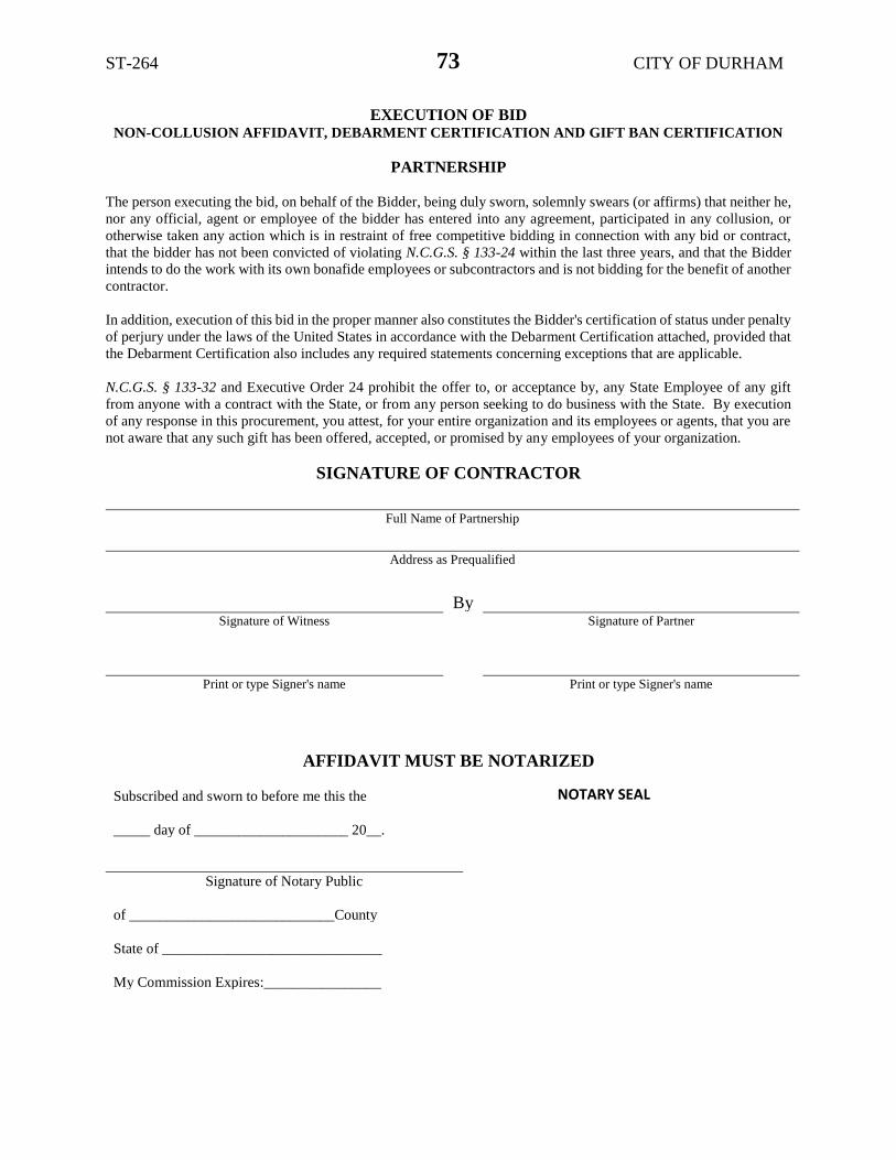
ST-264 CITY OF DURHAM
73
EXECUTION OF BID NON-COLLUSION AFFIDAVIT, DEBARMENT CERTIFICATION AND GIFT BAN CERTIFICATION
PARTNERSHIP
The person executing the bid, on behalf of the Bidder, being duly sworn, solemnly swears (or affirms) that neither he,
nor any official, agent or employee of the bidder has entered into any agreement, participated in any collusion, or
otherwise taken any action which is in restraint of free competitive bidding in connection with any bid or contract,
that the bidder has not been convicted of violating N.C.G.S. § 133-24 within the last three years, and that the Bidder
intends to do the work with its own bonafide employees or subcontractors and is not bidding for the benefit of another
contractor.
In addition, execution of this bid in the proper manner also constitutes the Bidder's certification of status under penalty
of perjury under the laws of the United States in accordance with the Debarment Certification attached, provided that
the Debarment Certification also includes any required statements concerning exceptions that are applicable.
N.C.G.S. § 133-32 and Executive Order 24 prohibit the offer to, or acceptance by, any State Employee of any gift
from anyone with a contract with the State, or from any person seeking to do business with the State. By execution
of any response in this procurement, you attest, for your entire organization and its employees or agents, that you are
not aware that any such gift has been offered, accepted, or promised by any employees of your organization.
SIGNATURE OF CONTRACTOR
Full Name of Partnership
Address as Prequalified
By Signature of Witness Signature of Partner
Print or type Signer's name Print or type Signer's name
AFFIDAVIT MUST BE NOTARIZED
Subscribed and sworn to before me this the
_____ day of _____________________ 20__.
Signature of Notary Public
of ____________________________County
State of ______________________________
My Commission Expires:________________
NOTARY SEAL

ST-264 CITY OF DURHAM
74
EXECUTION OF BID NON-COLLUSION AFFIDAVIT, DEBARMENT CERTIFICATION AND GIFT BAN CERTIFICATION
LIMITED LIABILITY COMPANY
The person executing the bid, on behalf of the Bidder, being duly sworn, solemnly swears (or affirms) that neither he,
nor any official, agent or employee of the bidder has entered into any agreement, participated in any collusion, or
otherwise taken any action which is in restraint of free competitive bidding in connection with any bid or contract,
that the bidder has not been convicted of violating N.C.G.S. § 133-24 within the last three years, and that the Bidder
intends to do the work with its own bonafide employees or subcontractors and is not bidding for the benefit of another
contractor.
In addition, execution of this bid in the proper manner also constitutes the Bidder's certification of status under penalty
of perjury under the laws of the United States in accordance with the Debarment Certification attached, provided that
the Debarment Certification also includes any required statements concerning exceptions that are applicable.
N.C.G.S. § 133-32 and Executive Order 24 prohibit the offer to, or acceptance by, any State Employee of any gift
from anyone with a contract with the State, or from any person seeking to do business with the State. By execution
of any response in this procurement, you attest, for your entire organization and its employees or agents, that you are
not aware that any such gift has been offered, accepted, or promised by any employees of your organization.
SIGNATURE OF CONTRACTOR
Full Name of Firm
Address as Prequalified
Signature of Witness Signature of Member/Manager/Authorized Agent
Select appropriate title
Print or type Signer's name Print or type Signer's Name
AFFIDAVIT MUST BE NOTARIZED
Subscribed and sworn to before me this the
_____ day of _____________________ 20__.
Signature of Notary Public
of ____________________________County
State of ______________________________
My Commission Expires:________________
NOTARY SEAL

ST-264 CITY OF DURHAM
75
EXECUTION OF BID NON-COLLUSION AFFIDAVIT, DEBARMENT CERTIFICATION AND GIFT BAN CERTIFICATION
JOINT VENTURE (2) or (3)
The person executing the bid, on behalf of the Bidder, being duly sworn, solemnly swears (or affirms) that neither he, nor any official, agent or
employee of the bidder has entered into any agreement, participated in any collusion, or otherwise taken any action which is in restraint of free
competitive bidding in connection with any bid or contract, that the bidder has not been convicted of violating N.C.G.S. § 133-24 within the last three years, and that the Bidder intends to do the work with its own bonafide employees or subcontractors and is not bidding for the benefit of
another contractor.
In addition, execution of this bid in the proper manner also constitutes the Bidder's certification of status under penalty of perjury under the laws of
the United States in accordance with the Debarment Certification attached, provided that the Debarment Certification also includes any required statements concerning exceptions that are applicable.
N.C.G.S. § 133-32 and Executive Order 24 prohibit the offer to, or acceptance by, any State Employee of any gift from anyone with a contract with
the State, or from any person seeking to do business with the State. By execution of any response in this procurement, you attest, for your entire
organization and its employees or agents, that you are not aware that any such gift has been offered, accepted, or promised by any employees of your organization.
SIGNATURE OF CONTRACTOR
Instructions: 2 Joint Venturers Fill in lines (1), (2) and (3) and execute. 3 Joint Venturers Fill in lines (1), (2), (3) and (4) and execute. On Line
(1), fill in the name of the Joint Venture Company. On Line (2), fill in the name of one of the joint venturers and execute below in the appropriate
manner. On Line (3), print or type the name of the other joint venturer and execute below in the appropriate manner. On Line (4), fill in the name of the third joint venturer, if applicable and execute below in the appropriate manner.
(1)
Name of Joint Venture
(2)
Name of Contractor
Address as Prequalified Signature of Witness or Attest By Signature of Contractor Print or type Signer's name Print or type Signer's name
If Corporation, affix Corporate Seal and
(3)
Name of Contractor Address as Prequalified Signature of Witness or Attest By Signature of Contractor Print or type Signer's name Print or type Signer's name
If Corporation, affix Corporate Seal and
(4) Name of Contractor (for 3 Joint Venture only)
Address as Prequalified
Signature of Witness or Attest By Signature of Contractor
Print or type Signer's name Print or type Signer's name
If Corporation, affix Corporate Seal
NOTARY SEAL NOTARY SEAL NOTARY SEAL
Affidavit must be notarized for Line (2) Affidavit must be notarized for Line (3) Affidavit must be notarized for Line (4)
Subscribed and sworn to before me this Subscribed and sworn to before me this Subscribed and sworn to before me this
_____day of______________________ 20___ _____day of ____________________ 20___ ____day of ___________________ 20_____
____________________________________ ____________________________________ ____________________________________
Signature of Notary Public Signature of Notary Public Signature of Notary Public of ____________________________County of ____________________________County of ____________________________County
State of ______________________________ State of _______________________________ State of ______________________________
My Commission Expires:________________ My Commission Expires:_________________ My Commission Expires:________________

ST-264 CITY OF DURHAM
76
EXECUTION OF BID NON-COLLUSION AFFIDAVIT, DEBARMENT CERTIFICATION AND GIFT BAN CERTIFICATION
INDIVIDUAL DOING BUSINESS UNDER A FIRM NAME
The person executing the bid, on behalf of the Bidder, being duly sworn, solemnly swears (or affirms) that neither he,
nor any official, agent or employee of the bidder has entered into any agreement, participated in any collusion, or
otherwise taken any action which is in restraint of free competitive bidding in connection with any bid or contract,
that the bidder has not been convicted of violating N.C.G.S. § 133-24 within the last three years, and that the Bidder
intends to do the work with its own bonafide employees or subcontractors and is not bidding for the benefit of another
contractor.
In addition, execution of this bid in the proper manner also constitutes the Bidder's certification of status under penalty
of perjury under the laws of the United States in accordance with the Debarment Certification attached, provided that
the Debarment Certification also includes any required statements concerning exceptions that are applicable.
N.C.G.S. § 133-32 and Executive Order 24 prohibit the offer to, or acceptance by, any State Employee of any gift
from anyone with a contract with the State, or from any person seeking to do business with the State. By execution
of any response in this procurement, you attest, for your entire organization and its employees or agents, that you are
not aware that any such gift has been offered, accepted, or promised by any employees of your organization.
SIGNATURE OF CONTRACTOR
Name of Contractor
Individual name
Trading and doing business as
Full name of Firm
Address as Prequalified
Signature of Witness Signature of Contractor, Individually
Print or type Signer's name Print or type Signer’s name
AFFIDAVIT MUST BE NOTARIZED
Subscribed and sworn to before me this the
_____ day of _____________________ 20__.
Signature of Notary Public
of ____________________________County
State of ______________________________
My Commission Expires:________________
NOTARY SEAL
ST-264 CITY OF DURHAM
77
EXECUTION OF BID NON-COLLUSION AFFIDAVIT, DEBARMENT CERTIFICATION AND GIFT BAN CERTIFICATION
INDIVIDUAL DOING BUSINESS IN HIS OWN NAME The person executing the bid, on behalf of the Bidder, being duly sworn, solemnly swears (or affirms) that neither he, nor any
official, agent or employee of the bidder has entered into any agreement, participated in any collusion, or otherwise taken any
action which is in restraint of free competitive bidding in connection with any bid or contract, that the bidder has not been convicted
of violating N.C.G.S. § 133-24 within the last three years, and that the Bidder intends to do the work with its own bonafide
employees or subcontractors and is not bidding for the benefit of another contractor.
In addition, execution of this bid in the proper manner also constitutes the Bidder's certification of status under penalty of perjury
under the laws of the United States in accordance with the Debarment Certification attached, provided that the Debarment
Certification also includes any required statements concerning exceptions that are applicable.
N.C.G.S. § 133-32 and Executive Order 24 prohibit the offer to, or acceptance by, any State Employee of any gift from anyone
with a contract with the State, or from any person seeking to do business with the State. By execution of any response in this
procurement, you attest, for your entire organization and its employees or agents, that you are not aware that any such gift has been
offered, accepted, or promised by any employees of your organization.
SIGNATURE OF CONTRACTOR
Name of Contractor Print or type Individual name
Address as Prequalified
Signature of Contractor, Individually
Print or type Signer's Name
Signature of Witness
Print or type Signer’s name
AFFIDAVIT MUST BE NOTARIZED
Subscribed and sworn to before me this the
_____ day of _____________________ 20__.
Signature of Notary Public
of ____________________________County
State of ______________________________
My Commission Expires:________________
NOTARY SEAL

ST-264 CITY OF DURHAM
78
DEBARMENT CERTIFICATION
Conditions for certification:
1. The prequalified bidder shall provide immediate written notice to the Municipality if at any
time the bidder learns that his certification was erroneous when he submitted his debarment
certification or explanation filed with the Municipality, or has become erroneous because of
changed circumstances.
2. The terms covered transaction, debarred, suspended, ineligible, lower tier covered
transaction, participant, person, primary covered transaction, principal, proposal, and
voluntarily excluded, as used in this provision, have the meanings set out in the Definitions
and Coverage sections of the rules implementing Executive Order 12549. A copy of the
Federal Rules requiring this certification and detailing the definitions and coverages may be
obtained from the Municipality project representative.
3. The prequalified bidder agrees by submitting this form, that he will not knowingly enter into
any lower tier covered transaction with a person who is debarred, suspended, declared
ineligible, or voluntarily excluded from participation in Municipal contracts, unless authorized
by the Municipality.
4. For Federal Aid projects, the prequalified bidder further agrees that by submitting this form he
will include the Federal-Aid Provision titled Required Contract Provisions Federal-Aid
Construction Contract (Form FHWA PR 1273) provided by the Municipality, without
subsequent modification, in all lower tier covered transactions.
5. The prequalified bidder may rely upon a certification of a participant in a lower tier covered
transaction that he is not debarred, suspended, ineligible, or voluntarily excluded from the
covered transaction, unless he knows that the certification is erroneous. The bidder may decide
the method and frequency by which he will determine the eligibility of his subcontractors.
6. Nothing contained in the foregoing shall be construed to require establishment of a system of
records in order to render in good faith the certification required by this provision. The
knowledge and information of a participant is not required to exceed that which is normally
possessed by a prudent person in the ordinary course of business dealings.
7. Except as authorized in paragraph 6 herein, the Municipality may terminate any contract if the
bidder knowingly enters into a lower tier covered transaction with a person who is suspended,
debarred, ineligible, or voluntarily excluded from participation in this transaction, in addition
to other remedies available by the Federal Government.

ST-264 CITY OF DURHAM
79
DEBARMENT CERTIFICATION
The prequalified bidder certifies to the best of his knowledge and belief, that he and his principals:
a. Are not presently debarred, suspended, proposed for debarment, declared ineligible, or
voluntarily excluded from covered transactions by any Federal department or agency;
b. Have not within a three-year period preceding this proposal been convicted of or had a civil
judgment rendered against them for commission of fraud or a criminal offense in connection with obtaining, attempting to obtain, or performing a public (Federal, State or local) transaction or contract under a public transaction; violation of Federal or State antitrust statutes or commission of embezzlement, theft, forgery, bribery, falsification or destruction of records; making false statements; or receiving stolen property;
c. Are not presently indicted for or otherwise criminally or civilly charged by a governmental
entity (Federal, State or local) with commission of any of the offenses enumerated in paragraph b. of this certification; and
d. Have not within a three-year period preceding this proposal had one or more public
transactions (Federal, State or local) terminated for cause or default.
e. Will submit a revised Debarment Certification immediately if his status changes and will show
in his bid proposal an explanation for the change in status.
If the prequalified bidder cannot certify that he is not debarred, he shall provide an explanation with this submittal. An explanation will not necessarily result in denial of participation in a contract.
Failure to submit a non-collusion affidavit and debarment certification will result in the
prequalified bidder's bid being considered non-responsive.
Check here if an explanation is attached to this certification.

ST-264 CITY OF DURHAM
80
ITEM SHEETS BUXTON RIDDLE ROAD
Item No
Section No
Item Description Units QTY Unit Price Item Cost
1 800 MOBILIZATION LS 1
2 801 CONSTRUCTION SURVEYING LS 1
3 801 SUPPLEMENTAL FIELD SURVEYING HR 20
4 801 SUPPLEMENTAL SURVEYING OFFICE CALCULATION HR 20
5 225 UNDERCUT EXCAVATION CY 300
6 226 GRADING LS 1
7 260 PROOF ROLLING HR 15
8 300 FOUNDATION CONDITIONING MATERIAL, MINOR STRUCTURES TON 225
9 310 15" RC PIPE CULVERTS, CLASS III LF 780
10 310 18" RC PIPE CULVERTS, CLASS III LF 880
11 310 24" RC PIPE CULVERTS, CLASS III LF 240
12 310 48" RC PIPE CULVERTS, CLASS III LF 100
13 310 15" CS PIPE CULVERTS, 0.064" THICK LF 60
14 340 PIPE REMOVAL LF 1,100
15 SP #57 STONE TON 100
16 505 SHALLOW UNDERCUT CY 60
17 505 CLASS IV SUBGRADE STABILIZATION TON 200
18 SP GEOTEXTILE FOR PAVEMENT STABILIZATION SY 175
19 520 AGGREGATE BASE COURSE TON 2,500
20 607 MILLING ASPHALT PAVEMENT, 1 1/2" DEPTH SY 7,000
21 607 INCIDENTAL MILLING SY 150
22 610 ASPHALT CONC. BASE COURSE, TYPE B25.0C TON 2,000
23 610 ASPHALT CONC. INTERMEDIATE COURSE, TYPE I19.0C TON 1,500
24 610 ASPHALT CONC. SURFACE COURSE, TYPE S9.5C TON 2,000
25 620 ASPHALT BINDER FOR PLANT MIX, GRADE PG 64-22 TON 160
26 620 ASPHALT BINDER FOR PLANT MIX, GRADE PG 70-22 TON 120

ST-264 CITY OF DURHAM
81
Item No
Section No
Item Description Units Quantity Unit Price Item Cost
27 806 RIGHT OF WAY MARKERS EA 19
28 828 TEMPORARY STEEL PLATE COVERS FOR MASONRY DRAINAGE EA 3
29 840 PIPE COLLAR CY 1
30 840 MASONRY DRAINAGE STRUCTURES EA 29
31 840 MASONRY DRAINAGE STRUCTURES LF 6
32 840 FRAME WITH TWO GRATES, STD 840.16 EA 5
33 840 FRAME WITH GRATE & HOOD, STD 840.03, TYPE "E" EA 19
34 840 FRAME WITH GRATE & HOOD, STD 840.03, TYPE "F" EA 3
35 840 FRAME WITH GRATE & HOOD, STD 840.03, TYPE "G" EA 11
36 840 FRAME WITH COVER, STD 840.54 EA 6
37 SP UNDERGROUND DETENTION CONTROL STRUCTURE 5A EA 1
38 SP UNDERGROUND DETENTION CONTROL STRUCTURE 6A EA 1
39 846 1'-6" CONCRETE CURB & GUTTER LF 200
40 846 2'-6" CONCRETE CURB & GUTTER LF 3,800
41 848 4" CONCRETE SIDEWALK SY 2,000
42 848 6" CONCRETE SIDEWALK SY 30
43 848 CONCRETE WHEELCHAIR RAMPS EA 20
44 848 6" CONCRETE DRIVEWAY SY 350
45 850 4" CONCRETE PAVED DITCH SY 2
46 852 4" CONCRETE ISLAND COVERS SY 90
47 858 ADJUSTMENT OF CATCH BASINS EA 1
48 858 ADJUSTMENT OF MANHOLES EA 20
49 858 ADJUSTMENT OF METER BOXES OR VALVE BOXES EA 15
50 859 CONVERT EXISTING CATCH BASIN TO JUNCTION BOX WITH MH COVER
EA 1
51 862 STEEL BM GUARDRAIL LF 225
52 SP IMPACT ATTENUATOR UNITS, TL-2 EA 2

ST-264 CITY OF DURHAM
82
Item No
Section No
Item Description Units Quantity Unit Price Item Cost
53 876 RIP RAP, CLASS B TON 15
54 876 FILTER FABRIC FOR DRAINAGE SY 30
55 901 CONTRACTOR FURNISHED, TYPE "E" SIGN SF 150
56 903 SUPPORTS, 3-LB STEEL U-CHANNEL LF 375
57 904 SIGN ERECTION, TYPE E EA 18
58 904 SIGN ERECTION, RELOCATE, TYPE E (GROUND MOUNTED) EA 6
59 907 DISPOSAL OF SIGN SYSTEM, U-CHANNEL EA 4
60 907 DISPOSAL OF SUPPORT, U-CHANNEL EA 5
61 1110 WORK ZONE SIGNS (STATIONARY) SF 175
62 1110 WORK ZONE SIGNS (PORTABLE) SF 400
63 1110 WORK ZONE SIGNS (BARRICADE MOUNTED) SF 150
64 1115 FLASHING ARROW PANELS, TYPE C EA 2
65 1120 PORTABLE CHANGEABLE MESSAGE SIGN EA 4
66 1130 DRUMS EA 250
67 1135 CONES EA 100
68 1145 BARRICADES (TYPE III) LF 80
69 1150 FLAGGER HR 100
70 1165 TMA EA 2
71 1180 SKINNY DRUM EA 100
72 SP TEMPORARY CONSTRUCTION ENTRANCE EA 2
73 1205 THERMOPLASTIC PAVEMENT MARKING LINES (4", 90 MILS) LF 1,350
74 1205 THERMOPLASTIC PAVEMENT MARKING LINES (4", 120 MILS) LF 9,200
75 1205 THERMOPLASTIC PAVEMENT MARKING LINES (8", 90 MILS) LF 400
76 1205 THERMOPLASTIC PAVEMENT MARKING LINES (8", 120 MILS) LF 625
77 1205 THERMOPLASTIC PAVEMENT MARKING LINES (24", 120 MILS) LF 340
78 1205 THERMOPLASTIC PAVEMENT CHARACTER (120 MILS) EA 16

ST-264 CITY OF DURHAM
83
Item No
Section No
Item Description Units Quantity Unit Price Item Cost
79 1205 THERMOPLASTIC PAVEMENT SYMBOL (90 MILS) EA 59
80 1205 PAINT PAVEMENT MARKING LINES (4") LF 13,000
81 1205 PAINT PAVEMENT MARKING LINES (24") LF 225
82 1205 PAINT PAVEMENT MARKING SYMBOL EA 15
83 1205 REMOVAL OF PAVEMENT MARKING LINES (4") LF 7,500
84 1205 REMOVAL OF PAVEMENT MARKING LINES (24") LF 150
85 1205 REMOVAL OF PAVEMENT MARKING SYMBOLS & CHARACTERS EA 8
86 1253 SNOWPLOWABLE PAVEMENT MARKERS EA 235
87 1515 RELOCATE WATER METER EA 10
88 1515 RELOCATE FIRE HYDRANT EA 2
89 1631 TEMPORARY SILT FENCE LF 3,300
90 SP TREE PROTECTION FENCE LF 200
91 1610 STONE FOR EROSION CONTROL, CLASS A TON 16
92 1610 STONE FOR EROSION CONTROL, CLASS B TON 90
93 1610 SEDIMENT CONTROL STONE TON 140
94 1615 TEMPORARY MULCHING ACR 1
95 1620 FERTILIZER FOR TEMPORARY SEEDING TON 0
96 1630 SILT EXCAVATION CY 1,500
97 SP SYNTHETIC ROVING SY 700
98 SP COIR FIBER BAFFLES LF 100
99 SP 1.5" SKIMMER EA 1
100 1660 SEEDING & MULCHING ACR 2
101 1660 MOWING ACR 1
102 1662 SEED FOR REPAIR SEEDING LB 50
103 1661 FERTILIZER FOR REPAIR SEEDING TON 0.25
104 1662 SEED FOR SUPPLEMENTAL SEEDING LB 40

ST-264 CITY OF DURHAM
84
Item No
Section No
Item Description Units Quantity Unit Price Item Cost
105 1665 FERTILIZER TOPDRESSING TON 0.32
106 1705 PEDESTRIAN SIGNAL HEAD (12", 1 SECTION) EA 8.00
107 1705 SIGNAL CABLE LF 2,605.00
108 1705 VEHICLE SIGNAL HEAD (12", 1 SECTION) EA 4.00
109 1705 VEHICLE SIGNAL HEAD (12", 3 SECTION) EA 3.00
110 1705 VEHICLE SIGNAL HEAD (12", 4 SECTION) EA 1.00
111 1705 VEHICLE SIGNAL HEAD (12", 5 SECTION) EA 1.00
112 1706 BACKPLATE EA 9.00
113 1715 TRACER WIRE LF 2,070.00
114 1715 TRENCHING (UNPAVED) LF 2,100.00
115 1715 DIRECTIONAL DRILL POLYETHYLENE, 2" (2 CONDUITS) LF 995.00
116 1716 JUNCTION BOX (STANDARD SIZE) EA 13.00
117 1716 JUNCTION BOX (OVER-SIZED) EA 11.00
118 1721 GUY ASSEMBLY EA 2.00
119 1722 2" RISER WITH HEAT SHRINK TUBING EA 2.00
120 1725 INDUCTIVE LOOP SAWCUT LF 1,920.00
121 1726 TYPE 2 LEAD-IN CABLE LF 4,015.00
122 1730 COMMUNICATIONS DROP CABLE (12 FIBER) LF 310.00
123 1730 COMMUNICATIONS CABLE (12 FIBER) LF 2,650.00
124 1730 COMMUNICATIONS CABLE (24 FIBER) LF 740.00
125 1731 INTERCONNECT CENTER EA 2.00
126 1732 FIBER-OPTIC TRANSCEIVER EA 1.00
127 SP SIGNAL SUPPORT MAST ARM WITH METAL POLE EA 5.00
128 SP METAL SIGNAL POLE FOUNDATION EA 5.00
129 SP SOIL TEST EA 5.00
130 1743 TYPE I POST WITH FOUNDATION EA 8.00

ST-264 CITY OF DURHAM
85
Item No
Section No
Item Description Units Quantity Unit Price Item Cost
131 1743 TYPE II POST WITH FOUNDATION EA 2.00
132 SP MASTARM WITH METAL POLE DESIGN EA 5.00
133 1745 SIGN FOR SIGNALS EA 7.00
134 1750 SIGNAL CABINET FOUNDATION EA 1.00
135 1752 CONDUIT ENTRANCE INTO EXISTING FOUNDATION EA 1.00
136 1751 CONTROLLER WITH CABINET (TYPE 170E, BASE MOUNTED) EA 1.00
137 1751 CONTROLLER WITH CABINET (TYPE 170E, POLE MOUNTED) EA 1.00
138 1751 DETECTOR CHANNEL (TYPE 170) EA 20.00
139 SP NEW ELECTRICAL SERVICE EA 1.00
140 SP VIDEO TRANSCEIVER EA 1.00
141 SP CCTV ASSEMBLY EA 1.00
142 SP CCTV POLE MOUNTED CABINET EA 1.00
143 SP COMMUNICATIONS CABLE REMOVAL LF 2,020.00
144 SP RETAINING WALL SF 200.00
145 SP BOLLARDS (HINGED AND UNHINGED) EA 6.00
TOTAL #1

ST-264 CITY OF DURHAM
86
ITEM SHEETS FAYETTEVILLE ROAD
Item No
Section No
Item Description Units QTY Unit Price Item Cost
1 800 MOBILIZATION LS 1
2 801 CONSTRUCTION SURVEYING LS 1
3 801 SUPPLEMENTAL FIELD SURVEYING HR 100
4 801 SUPPLEMENTAL SURVEYING OFFICE CALCULATIONS HR 100
5 200 CLEARING & GRUBBING (14.5 ACRES) LS 1
6 200 SUPPLEMENTARY CLEARING & GRUBBING AC 1
7 225 UNCLASSIFIED EXCAVATION CY 6,053
8 225 UNDERCUT EXCAVATION CY 500
9 230 BORROW EXCAVATION CY 63,550
10 240 DRAINAGE DITCH EXCAVATION CY 75
11 250 REMOVAL OF EXISTING ASPHALT SY 18,785
12 260 PROOF ROLLING HR 10
13 265 SELECT GRANULAR MATERIAL CY 17
14 270 GEOTEXTILE FOR SOIL STABILIZATION SY 1,350
15 300 FOUNDATION CONDITIONING MATERIAL, MINOR STRUCTURES TON 4,611
16 300 FOUNDATION CONDITIONING GEOTEXTILE SY 17,400
17 305 15" DRAINAGE PIPE LF 248
18 305 18" DRAINAGE PIPE LF 60
19 305 24" DRAINAGE PIPE LF 190
20 310 15" SIDE DRAIN PIPE LF 24
21 310 18" SIDE DRAIN PIPE LF 72
22 310 15" RC PIPE CULVERTS, CLASS III LF 360
23 310 18" RC PIPE CULVERTS, CLASS III LF 180
24 310 24" RC PIPE CULVERTS, CLASS III LF 44
25 310 15" RC PIPE CULVERTS, CLASS IV LF 2,400
26 310 18" RC PIPE CULVERTS, CLASS IV LF 696

ST-264 CITY OF DURHAM
87
Item No
Section No
Item Description Units Quantity Unit Price Item Cost
27 310 24" RC PIPE CULVERTS, CLASS IV LF 76
28 310 15" CS PIPE ELBOW, 0.064" THICK EA 6
29 310 24" CS PIPE ELBOW, 0.064" THICK EA 4
30 340 PIPE REMOVAL LF 621
31 350 PIPE CLEANOUT EA 3
32 500 FINE GRADING (55,900 SY) LS 1
33 SP #57 STONE TON 150
34 505 SHALLOW UNDERCUT CY 250
35 505 CLASS IV SUBGRADE STABILIZATION TON 750
36 SP GEOTEXTILE FOR PAVEMENT STABILIZATION SY 10,000
37 520 AGGREGATE BASE COURSE TON 12,800
38 545 INCIDENTAL STONE BASE TON 300
39 560 SHOULDER BORROW CY 375
40 600 PRIME COAT GAL 580
41 607 MILLING ASPHALT PAVEMENT, 1 1/2" DEPTH SY 27,798
42 607 INCIDENTAL MILLING SY 1,685
43 610 ASPHALT CONC. BASE COURSE, TYPE B25.0C TON 7,180
44 610 ASPHALT CONC. INTERMEDIATE COURSE, TYPE I19.0C TON 7,000
45 610 ASPHALT CONC. SURFACE COURSE, TYPE S9.5C TON 8,500
46 620 ASPHALT BINDER FOR PLANT MIX, GRADE PG 64-22 TON 675
47 620 ASPHALT BINDER FOR PLANT MIX, GRADE PG 70-22 TON 525
48 654 ASPHALT PLANT MIX, PAVEMENT REPAIR TON 100
49 806 RIGHT OF MARKERS EA 37
50 828 TEMPORARY STEEL PLATE COVERS FOR MASONRY DRAINAGE STR'S.
EA 5
51 840 PIPE COLLAR CY 1
52 840 PIPE PLUG CY 1

ST-264 CITY OF DURHAM
88
Item No
Section No
Item Description Units Quantity Unit Price Item Cost
53 SP FLOWABLE FILL CY 51
54 840 MASONRY DRAINAGE STRUCTURES EA 72
55 840 MASONRY DRAINAGE STRUCTURES LF 59
56 840 FRAME WITH GRATE, STD 840.16 EA 12
57 840 FRAME WITH TWO GRATES, STD 840.24 EA 3
58 840 FRAME WITH GRATE & HOOD, STD 840.03, TYPE "E" EA 11
59 840 FRAME WITH GRATE & HOOD, STD 840.03, TYPE "F" EA 21
60 840 FRAME WITH GRATE & HOOD, STD 840.03, TYPE "G" EA 19
61 840 FRAME WITH COVER, STD 840.54 EA 9
62 852 CONCRETE TRANSITIONAL SECTION FOR CATCH BASIN EA 8
63 846 1'-6" CONCRETE CURB & GUTTER LF 7,930
64 846 2'-6" CONCRETE CURB & GUTTER LF 10,550
65 848 4" CONCRETE SIDEWALK SY 5,005
66 848 6" CONCRETE SIDEWALK SY 150
67 848 CONCRETE CURB RAMPS EA 45
68 848 6" CONCRETE DRIVEWAY SY 770
69 852 5" MONOLITHIC CONCRETE ISLANDS (KEYED IN) SY 780
70 858 ADJUSTMENT OF MANHOLES EA 28
71 858 ADJUSTMENT OF METER BOXES OR VALVE BOXES EA 18
72 859 CONVERT EXISTING CATCH BASIN TO JUNCTION BOX WITH MH COVER
EA 1
73 859 CONVERT EXISTING DROP INLET TO JUNCTION BOX EA 2
74 862 STEEL BM GUARDRAIL LF 750
75 SP IMPACT ATTENUATOR UNITS, TL-2 EA 4
76 864 REMOVE & RESET EXISTING GUARDRAIL LF 250
77 867 CHAIN LINK FENCE RESET LF 160
78 SP METAL FENCE RESET LF 135

ST-264 CITY OF DURHAM
89
Item No
Section No
Item Description Units Quantity Unit Price Item Cost
79 SP BOLLARDS (HINGED AND UNHINGED) EA 12
80 876 RIP RAP, CLASS I TON 36
81 876 RIP RAP, CLASS B TON 37
82 876 GEOTEXTILE FOR DRAINAGE SY 600
83 901 CONTRACTOR FURNISHED, TYPE "E" SIGN SF 410
84 903 SUPPORTS, 3-LB STEEL U-CHANNEL LF 1,485
85 904 SIGN ERECTION, TYPE E EA 80
86 904 SIGN ERECTION, RELOCATE, TYPE D (GROUND MOUNTED) EA 13
87 904 SIGN ERECTION, RELOCATE, TYPE E (GROUND MOUNTED) EA 58
88 SP TRAIL SIGN RESET EA 2
89 SP SOLITE PARK SIGN, RELOCATE EA 1
90 SP UDI INDUSTRIAL PARK ENTRANCE SIGN, RELOCATE EA 2
91 907 DISPOSAL OF SIGN SYSTEM, U-CHANNEL EA 8
92 907 DISPOSAL OF SUPPORT, U-CHANNEL EA 57
93 907 DISPOSAL OF SIGN D, E, OR F EA 2
94 1110 WORK ZONE SIGNS (STATIONARY) SF 225
95 1110 WORK ZONE SIGNS (PORTABLE) SF 300
96 1110 WORK ZONE SIGNS (BARRICADE MOUNTED) SF 360
97 1115 FLASHING ARROW BOARD EA 2
98 1120 PORTABLE CHANGEABLE MESSAGE SIGN EA 6
99 1130 DRUMS EA 200
100 1145 BARRICADES (TYPE III) LF 816
101 1150 FLAGGER HR 1,000
102 1165 TMA EA 2
103 1170 WATER FILLED BARRIER LF 300
104 1170 RESET WATER FILLED BARRIER LF 300

ST-264 CITY OF DURHAM
90
Item No
Section No
Item Description Units Quantity Unit Price Item Cost
105 SP LAW ENFORCEMENT HR 40
106 1180 SKINNY DRUM EA 200
107 1251 TEMPORARY RAISED PAVEMENT MARKERS EA 500
108 1205 THERMOPLASTIC PAVEMENT MARKING LINES (4", 90 MILS) LF 3,700
109 1205 THERMOPLASTIC PAVEMENT MARKING LINES (4", 120 MILS) LF 18,600
110 1205 THERMOPLASTIC PAVEMENT MARKING LINES (8", 90 MILS) LF 1,300
111 1205 THERMOPLASTIC PAVEMENT MARKING LINES (8", 120 MILS) LF 2,600
112 1205 THERMOPLASTIC PAVEMENT MARKING LINES (24", 120 MILS) LF 2,000
113 1205 THERMOPLASTIC PAVEMENT CHARACTER (120 MILS) EA 2
114 1205 THERMOPLASTIC PAVEMENT SYMBOL (90 MILS) EA 158
115 1205 PAINT PAVEMENT MARKING LINES (4") LF 57,400
116 1205 PAINT PAVEMENT MARKING LINES (8") LF 3,900
117 1205 PAINT PAVEMENT MARKING LINES (24") LF 4,400
118 1205 PAINT PAVEMENT MARKING CHARACTER EA 2
119 1205 PAINT PAVEMENT MARKING SYMBOL EA 126
120 1205 REMOVAL OF PAVEMENT MARKING LINES (4") LF 28,000
121 1205 REMOVAL OF PAVEMENT MARKING LINES (8") LF 3,000
122 1205 REMOVAL OF PAVEMENT MARKING LINES (24") LF 970
123 1205 REMOVAL OF PAVEMENT MARKING SYMBOLS & CHARACTERS EA 60
124 1253 SNOWPLOWABLE PAVEMENT MARKERS EA 675
125 1264 OBJECT MARKERS (TYPE 1) EA 2
126 1515 RELOCATE FIRE HYDRANT EA 8
127 1605 TEMPORARY SILT FENCE LF 9,650
128 SP TREE PROTECTION FENCE LF 1,020
129 SP CATCH BASIN DRAIN FILTER SOCKS "SILT SOCK" EA 17
130 SP TEMPORARY CONSTRUCTION ENTRANCE EA 5

ST-264 CITY OF DURHAM
91
Item No
Section No
Item Description Units Quantity Unit Price Item Cost
131 1610 STONE FOR EROSION CONTROL, CLASS A TON 185
132 1610 STONE FOR EROSION CONTROL, CLASS B TON 110
133 1610 SEDIMENT CONTROL STONE TON 405
134 1615 TEMPORARY MULCHING ACR 13
135 1620 SEED FOR TEMPORARY SEEDING LB 1,200
136 1620 FERTILIZER FOR TEMPORARY SEEDING TON 6
137 1630 SILT EXCAVATION CY 2,000
138 1631 MATTING FOR EROSION CONTROL SY 6,570
139 SP PERMANENT SOIL REINFORCEMENT MAT SY 425
140 1632 1/4" HARDWIRE CLOTH LF 1,920
141 SP 12" TEMPORARY PIPE LF 20
142 SP 15" TEMPORARY PIPE LF 40
143 SP WATTLE LF 54
144 SP POLYACRYLAMIDE (PAM) LB 12
145 1640 COIR FIBER BAFFLES LF 270
146 SP 1.5" SKIMMER EA 1
147 SP 2.0" SKIMMER EA 1
148 1660 SEEDING & MULCHING ACR 18
149 1660 MOWING ACR 12
150 1661 SEED FOR REPAIR SEEDING LB 150
151 1661 FERTILIZER FOR REPAIR SEEDING TON 1
152 1662 SEED FOR SUPPLEMENTAL SEEDING LB 450
153 1665 FERTILIZER TOPDRESSING TON 12
154 1705 PEDESTRIAN SIGNAL HEAD (16", 1 SECTION WITH COUNTDOWN) EA 36
155 1705 SIGNAL CABLE LF 16,455
156 1705 VEHICLE SIGNAL HEAD (12", 3 SECTION) EA 71

ST-264 CITY OF DURHAM
92
Item No
Section No
Item Description Units Quantity Unit Price Item Cost
157 1705 VEHICLE SIGNAL HEAD (12", 4 SECTION) EA 3
158 1705 VEHICLE SIGNAL HEAD (12", 5 SECTION) EA 5
159 1710 MESSENGER CABLE (1/4") LF 2,370
160 1715 TRACER WIRE LF 3,395
161 1715 UNPAVED TRENCHING (2 conduits, 2 inch) LF 7,305
162 1715 DIRECTIONAL DRILL (2 conduits, 2 inch) LF 2,195
163 1716 JUNCTION BOX (STANDARD SIZE) EA 50
164 1716 JUNCTION BOX (OVER-SIZED, HEAVY DUTY) EA 10
165 1720 WOOD POLE EA 11
166 1721 GUY ASSEMBLY EA 23
167 1722 1/2" RISER WITH WEATHERHEAD EA 5
168 1722 1" RISER WITH WEATHERHEAD EA 1
169 1725 INDUCTIVE LOOP SAWCUT LF 7,340
170 1726 LEAD-IN CABLE (14-2) LF 23,895
171 1730 COMMUNICATIONS CABLE (24 FIBER) LF 3,775
172 1730 DROP CABLE LF 1,175
173 1731 SPLICE ENCLOSURE EA 2
174 1731 MODIFY SPLICE ENCLOSURE EA 3
175 1731 INTERCONNECT CENTER EA 4
176 1732 FIBER-OPTIC TRANSCEIVER, SELF-HEALING RING EA 3
177 1734 REMOVE EXISTING COMMUNICATIONS CABLE LF 3,110
178 SP METAL STRAIN SIGNAL POLE EA 2
179 SP METAL POLE WITH SINGLE MAST ARM EA 10
180 SP SOIL TEST EA 12
181 SP DRILLED PIER FOUNDATION* CY 67

ST-264 CITY OF DURHAM
93
Item No
Section No
Item Description Units Quantity Unit Price Item Cost
182 SP METAL STRAIN POLE DESIGN EA 2
183 SP MAST ARM WITH METAL POLE DESIGN EA 10
184 1745 SIGN FOR SIGNALS EA 38
185 1743 TYPE I POST WITH FOUNDATION EA 26
186 1743 TYPE II PEDESTAL WITH FOUNDATION EA 5
187 1743 TYPE III PEDESTAL WITH FOUNDATION EA 4
188 1747 LED BLANKOUT SIGN EA 5
189 1750 SIGNAL CABINET FOUNDATION EA 3
190 1752 CONDUIT ENTRANCE INTO EXISTING FOUNDATION EA 2
191 1751 CONTROLLER ONLY (TYPE 2070L) EA 1
192 1751 CONTROLLER WITH CABINET (TYPE 2070L, BASE MOUNTED) EA 3
193 1751 DETECTOR CARD (TYPE 2070L) EA 37
194 1753 CABINET BASE EXTENDER EA 3
195 SP METAL POLE FOUNDATION REMOVAL EA 2
196 SP METAL POLE REMOVAL EA 2
197 SP RELOCATE EXISTING CCTV CAMERA SSEMBLY EA 1
198 SP RELOCATE EXISTING FIELD EQUIPMENT CABINET EA 1
199 SP RELOCATE EXISTING COMMUNICATIONS EQUIPMENT EA 1
200 SP RELOCATE EXISTING ELECTRICAL SERVICE EA 1
201 SP RELOCATE EXISTING WOOD POLE EA 1
202 SP RELOCATE EXISTING WIRELESS RADIO EQUIPMENT EA 1
203 SP PROVIDE AND INSTALL RRFB PER DESIGN EA 1
TOTAL #2
GRAND TOTAL (TOTAL #1 + TOTAL #2)________________________________

APPENDIX A
UNDERUTILIZED BUSINESS ENTERPRISE (UBE)
REQUIREMENTS AND CONSTRUCTION FORMS
CONTRACT: ST-264

This page intentionally left blank

EO/EA CONSTRUCTION PROJECT MANUAL STATEMENT
It is the policy of the City to provide equal opportunities for City contracting to underutilized businesses owned by minorities and women doing business in the City’s Contracting Marketplace. It is further the policy of the City to prohibit discrimination against any firm in pursuit of these opportunities, to conduct its contracting activities so as to prevent such discrimination, to correct the present effects of past discrimination and to resolve complaints of discrimination. This policy applies to construction contracting. The City’s Department of Equal Opportunity / Equity Assurance Department has reviewed this proposed project and established Underutilized Business Enterprise (UBE) participation goals: Minority Business Enterprise (MUBE)-11% and Woman Business Enterprise (WUBE)-7%. A listing of firms from the HUB database is included in this project manual. Bidders may also use firms currently certified as MUBES and WUBES by N.C. D.O.T. and the SBA 8(a) Program to meet the participation requirements. The bids will be evaluated and the contract awarded in accordance with statutory public
contract requirements and as supplemented by the City of Durham’s Equal Business Opportunity Program Construction Forms included with this bid. The following forms are mandatory and must be filled out and returned with the bid proposal.
A. Bid Forms B. Non-Collusion Affidavit C. Bidder Safety Evaluation Questionnaire D. *** BID BOND IF applicable**** E. Equal Business Opportunity Program Construction Forms
1. Forms E-101 UBE Participation On Base Bid and/or E-102 UBE Participation On Bid Alternate
2. Form E-104 Employee Breakdown
Any bids submitted without these completed forms may be deemed as “non-responsive”. If there are any questions or problems in filling out the UBE forms, please contact:
City of Durham
Equal Opportunity/Equity Assurance Department (919) 560-4180


CITY OF DURHAM
EQUAL BUSINESS
OPPORTUNITYPROGRAM
CONSTRUCTION FORMS
Revised 3/2016
*
Phone: 919-560-4180
Facsimile: 919-560-4513
Street Address:
101 City Hall Plaza (Annex)
Durham, North Carolina 27701

2
INSTRUCTIONS ON UBE REQUIREMENTS
FOR USE IN BIDDING ON CONSTRUCTION PROJECTS WITH THE CITY OF DURHAM
These instructions summarize the provisions of the City of Durham’s Equal Business Opportunity Ordinance as it applies to the bid process. Of course, as with any summary, it cannot reflect all of the ordinance.
QUESTIONS AND ANSWERS ON UBE REQUIREMENTS
1. What is the purpose of the City’s Equal Business Opportunity (EBO) program? The City Manager has set UBE goals for certain contract classifications. There will be a goal for UBEs owned by minorities and a goal for UBEs owned by women. For the bid to be fully considered by the City, the bid needs to meet the established goals or the bidder needs to have made good-faith efforts to subcontract with UBEs in order to meet the goals. In order to be given credit for making those good-faith efforts, the bidder must provide written documentation of those good-faith efforts. That written documentation must be submitted to the City within 2 days after the bid opening unless a different time is stated by the City. See the instructions below regarding Form E-107.
2. What is an ―UBE‖? It means an Underutilized Business Enterprise. An UBE is a business, certified
by the N. C. Department of Administration HUB Office, N.C. Department of Transportation or the
U.S. Small Business Administration Section 8(a) Business Development Program as a minority or
women business enterprise. The qualifying UBE needs to have its certification from one of the
above named entities before the bid opening if it is to count toward meeting the goals. Failure to
provide evidence of UBE status may disqualify the firm’s participation for the purpose of meeting
UBE goals
For purposes of this document and associated forms, any reference to an “UBE,” or similar reference shall
include reference to a qualified women or minority owned firm certified and approved in accordance with
the above paragraphs.
3. What UBE forms must a bidder or contractor turn in to the City, and when?
Name or description of form Necessary to submit this form? When to submit it?
E-101 (UBE PARTICIPATION
ON BASE BID)
Always With the bid
E-102 (UBE PARTICIPATION
ON BID ALTERNATE)
Yes, if there are alternates. Use a
separate form for each alternate.
With the bid
E-103 reserved for future use) n/a n/a
E-104 (EMPLOYEE BREAKDOWN)
Yes or a EEO-1 form if large enough to report employment statistics to the federal government.
With the bid

3
UBE forms continued
E-105 (STATEMENT OF
INTENT TO PERFORM AS
SUBCONTRACTOR)
Yes, if the bidder proposes to
count any subcontracts with
UBEs towards the UBE goals
Within 5 days after bid
opening unless a
different time is stated
by the City.
E-106 (REQUEST TO CHANGE
UBE PARTICIPATION AFTER
BID OPENING)
Yes, if the bidder or contractor proposes certain changes in its subcontracting
Not with the bid. Once the bidder is identified as the apparent lowest responsible bidder, this form is due before the bidder/contractor can make the proposed change.
E-107 (QUESTIONNAIRE ON
BIDDER’S GOOD-FAITH
EFFORTS)
Yes, if the bidder fails to meet the
UBE goals. Do not turn in if the
bidder met the goals.
Within 2 days after bid
opening unless a
different time is stated
by the City
Good-faith documentation Yes, if the bidder failed to
meet the UBE goals.
Within 2 days after bid
opening unless a
different time is stated
by the City

4
4. If a bidder fails to meet the UBE goals, can it still be awarded the contract? Bidders that do not meet the goals but demonstrate good-faith efforts are treated equally to those that meet the goals. Awarding a contract is ultimately the decision of the City Council, which considers compliance with the EBO ordinance along with other matters.
5. In making good-faith efforts, what UBEs should a potential bidder contact? The City provides a
list of UBEs that have been certified by the N. C. Department of Administration HUB Office, as a
minority or women business enterprise for particular trades, services, goods, etc. Potential bidders
should contact UBEs listed for the work that can be subcontracted.
6. Our firm already has employees who can do the work and does not want to subcontract that
work. How does this fit in? The purpose of the EBO ordinance is to change business practices that
would otherwise occur, by giving opportunities to under-used segments of the economy. If the bidder
does not meet the goals, its good-faith efforts will be examined as with any other bidder that did not meet
the goals.
7. If the bidder contacts an underutilized business enterprise owned by a minority or woman that
could become a UBE, will that count toward good-faith efforts? This contact will not count unless the
firm that you contact is certified by the N. C. Department of Administration HUB Office, N.C. Department
of Transportation or the U.S. Small Business Administration Section (a) Business Development Program
as a minority or women business enterprise before the bids are opened. In making good-faith efforts, let
us suppose that a potential bidder contacts firms that could qualify to be UBEs. If those firms have their
certification from the previously identified authorities at the time of the bid opening, those contacts will
count towards good-faith efforts. But there is a risk, because getting certification takes time.
8. Do all subcontracts with UBEs count? The City will count as UBE participation only expenditures to an
UBE that performs a commercially-useful function in the relevant work. An UBE performs such a function
when the minority or women business owners themselves are actually involved in performing, managing,
and supervising a distinct element of the work. To determine whether those requirements are met, the
City takes into account the amount of work subcontracted, industry practices, the adequacy of the
resources of the UBE for the work, the qualifications, such as possession of licenses, permits, and
professional designations of the minority and women owners, and other relevant factors. For example, if
an UBE lacks substantially all of the resources equipment and personnel to do the work it shall be
presumed not to perform a commercially-useful function. The EBO ordinance includes more points to
consider on this issue.
9. May an UBE enter into subcontracts? This question arises in two situations: (1) the bidder is an
UBE and (2) the bidder is subcontracting with an UBE. Consistent with normal industry practices, an
UBE may enter into subcontracts. If an UBE subcontracts a significantly greater portion of the work of
the contract than would be expected on the basis of normal industry practices, the UBE shall be
presumed not to be performing a commercially-useful function. The UBE may present evidence to
rebut this presumption to the City.
10. What does it mean to say that information must be submitted ―with the bid‖? Unless bidders are given other written instructions from the City, it means that the information must be in a sealed envelope, delivered to the same place where a bid can be delivered, and before the time set for the bid opening. Unless bidders are given other written instructions from the City, the information can be either in the same envelope as the bid or in a separate envelope. If it is a separate envelope, the outside of the envelope must state the same information that is required on the bid envelope, and that it contains UBE forms.

5
11. When the chart in question 3 says that a form can be submitted 2 days or 5 days after the bid
opening, exactly when is it due? Where is it to be submitted?
. The form must be submitted to the City’s EOEA Department, located at 101 City Hall Annex or
faxed/emailed to (919) 560-4513, so that it is received within 2 days or 5 days (whichever applies
according to the chart) after the bid opening. If the form is faxed/emailed, it must be received before
midnight on that 2nd
or 5th
day. If it is delivered by any other means, it must be received before 5:00 PM.
In counting these 2 days or 5 days, exclude the following: the day of the bid opening, Saturday, Sunday,
and holidays observed by city government of the City of Durham. For instance, for a form due in 2 days, if
the bid opening is on a Thursday, the due date for the form would be on the following Monday (midnight if
faxed, otherwise 5:00 PM). If the day after the bid opening or that Monday is a City holiday, the form would
be due on Tuesday. For a form due in 5 days, if the bid opening were on Tuesday, the due date for the
form would be on the following Tuesday (midnight if faxed, otherwise 5:00 PM). If any weekday between
those Tuesdays is a City holiday or if the Tuesday on which the form would be due is a City holiday, the
form would be due on Wednesday. It is best to place the documents inside an envelope, and to write on
the outside of the envelope the same information that is required on the bid envelope, and that it contains
UBE forms. Holidays observed by city government are New Years' Day, Dr. Martin Luther King, Jr., Day;
Good Friday, Memorial Day, Independence Day, Labor Day, Thanksgiving Day, the day after
Thanksgiving Day, Christmas Day; two days (varying from year to year) during the week of Christmas
Day; and other times as may be authorized by City Council.
12. When there are bid alternates how is UBE participation counted? The total amount of the award
actually made by the City is the key. For instance, assume the following made-up example:
Base bid is $200,000
Alternate A bid is $50,000
Alternate B bid is $22,000
Minority-owned UBE goal is 11%. The bidder proposes Minority-owned UBE participation as follows: $22,000 on the base bid, $4,000 on Alternate A, and $10,000 on Alternate B.
In this fictional example, the bidder may or may not meet the goal, depending on the actual award by Council. This chart illustrates:

6
A W A R D B Y C I T Y C O U N C I L
Only the base bid
Base bid + Alternate A Base bid + Alternate B Base bid + Alternates A & B
Bid total $200,000 $250,000
(200,000 + 50,000)
$220,000
(200,000 + 20,000)
$270,000 (200,000 + 70,000)
Total UBE participation
$22,000 $26,000 (22,000 + 4,000)
$32,000
(22,000 + 10,000)
$36,000
(22,000 + 14,000)
Minority‐owned
UBE
percentage
11% 10.4% 14.5% 13.3%
Meet 11%
Minority‐ owned UBE goal?
Yes No Yes Yes
14. How is the lease of equipment by an UBE counted? If the UBE leases equipment for the work of the
contract, the value of the lease payments is included as part of the UBE’s participation. However, it is not proper to include such lease payments if they are to be made to the prime contractor or the prime
contractor’s “Affiliate.” To understand what an “Affiliate” is, see section 26‐3 of the EBO ordinance.
15. How is the purchase of goods from an UBE counted? If the bidder is buying goods from an UBE, the
cost of the goods can be considered UBE participation only if (a) the UBE operates or maintains a factory
that produces the goods, or (b) the UBE has an establishment where the goods of the general character
described by the specifications or required under the Contract are regularly sold or leased to the public in
the usual course of business. If (b) applies, the UBE’s principal business must be selling or leasing those
goods and the UBE must operate under its own name
INSTRUCTIONS FOR INDIVIDUAL UBE BID FORMS FOR CONSTRUCTION
Form E-101 (UBE PARTICIPATION) On this form, “participation” is the dollar amount of subcontracts for
significant goods and services to be used to perform the contract. For instance, if the bidder would enter into
subcontract with UBEs for a total of $30,000, that would be the UBE participation amount. The sum of UBE
participation and non-UDBE participation should equal the amount of the bid. Form E-101 is required for the
base bid
Form E-102 (UBE PARTICIPATION ON BID ALTERNATE) This form is essentially the same as Form E-
101, except that it is used for the alternate bids instead of the base bid. Use a separate Form E-102 for each
alternate bid.
Form E-103 reserved for future use

7
Form E-104 (EMPLOYEE BREAKDOWN) Complete Part A for the primary location where the goods and services that are the subject of the bid are to be made or provided. If the parent company or other locations of the bidder are providing any substantial portion of the goods or services, then the bidder must also complete Part B, for the consolidated company. If the bidder has an EEO-1 Report that provides the same information as required on the Form E-104, the EEO-1 Report may be used instead. On whether to submit Form E-104, see question 3 above. See questions 3 and 11 above on when and where to turn in this form.
Form E-105 (STATEMENT OF INTENT TO PERFORM AS SUBCONTRACTOR) The bidder must provide a Form E-105 (Statement of Intent) for each UBE firm that the bidder would subcontract with if the City awards the contract to the bidder. See questions 3 and 11 above on when and where to turn in this form.
On Form E-105, what happens if column 2 (dollar amount) disagrees with column 3 (percentage)? If there is a conflict between the dollar amount in Column 2 and the percentage of base bid in Column 3, the percentage stated in Column 3 will control. For instance, if Column 2 if $10,000, Column 3 is 10%, and the base bid is $200,000, there is an error, because ten percent of $200,000 is $20,000, not $10,000. In that example, the form will be read as a commitment for $20,000. If the UBE both (i) is doubtful of its arithmetic and (ii) wants Column 2 to control in case of disagreement, it may say that Column 2 will control over Column 3, but to do so, it must write that on Form E-105.
E-106 (REQUEST TO CHANGE UBE PARTICIPATION AFTER BID OPENING) When is this form used? Beginning with the time that the City Manager identifies a bidder as the apparent lowest responsible bidder and continuing as that bidder is awarded the contract and continuing until that bidder/contractor reaches the point of final completion of the work, Form E-106 is to be used when the following occurs: If the bidder/contractor proposes to do any of the following ;
to replace a subcontractor, to perform subcontracted work with the bidder/contractor’s own forces, to increase the quantity of subcontracted work, to decrease the quantity of subcontracted work, or to change the allocation of work among subcontractors,
then the bidder/contractor must make good-faith efforts to attain the goals that it has shown on the E-101 and applicable E-102 forms, and the bidder/contractor must fill out Form E-106. Substitutions of subcontractors in these circumstances, both before and after the awarding of a contract, are subject to City approval. Consult the City’s EO/EA Department on the procedures to follow in order to comply with City Code 26- 10(c).
E-106 (QUESTIONNAIRE ON BIDDER’S GOOD-FAITH EFFORTS) Bidders that do not attain the UBE goals have the responsibility to make good-faith efforts and to demonstrate to the City that they have made such efforts. In determining a bidder’s good-faith efforts to engage UBEs, the City Manager shall consider the information supplied by the bidder to answer the questions in Form E-107, along with other criteria that the City Manager deems proper. Form E-107 is an optional tool that bidders may use to show that they have made good-faith efforts. See questions 3 and 11 above on when and where to turn in this form. Even when this form may be submitted after the bid opening, it cannot include information on efforts made after the bid opening. Even if a bidder does not use Form E-107, the City will nevertheless attempt to answer the questions on the E-107 using good-faith documentation supplied by the bidder. Bidders who do not turn in Form E-107 will still find it helpful to know how the City will determine whether good-faith efforts have been made.

8
For Section 2 of Form E-107 -- To make the best good-faith efforts as described under Section 2 on E-107,
your firm should have sent a written letter, email, phone call or fax to all UBEs on the City’s list that perform
the kind of work to be subcontracted. Your firm needs to keep a record of all of these attempts to reach
UBEs. That letter would say, in effect, as follows: (Of course, your firm would need to write appropriate words
where italicized instructions are used below.)
Our firm is interested in bidding on a contract with the City of Durham for [describe the project]. We
are interested in subcontracting, to your firm, the following work [describe specific work, for example,
painting of interiors of 5 rooms, including prep work; or supplying 20 circuit breakers of type XJE‐R or
equivalent]. You may inspect the applicable plans and specifications and descriptions of items to be
purchased at our office located at the address shown above, or at the City of Durham’s EO/EA
Department, 101 City Hall Plaza Annex , Durham, N.C., 27701 , 919‐560‐ 4180[, or at the AGC plan
room in (specify the locations)]. You may obtain a copy [explain how and from whom (the City,
architect, engineer, etc.) the potential subs can obtain a copy].
If applicable, tell the UBEs at which offices of the AGC the plans and specifications may be seen, possibly from the following AGC list.
1100 Euclid Avenue
Charlotte, NC 28203-1868
Phone: (704)372-1450
Caswell Bldg., Glenwood
Place 3700 National Drive,
Ste. 201
Raleigh, NC 27612
Phone: (919)781-3270 2713 Breezewood Avenue
Fayetteville, NC 28303 Phone: (910)484-0184
2527 S. 17th St.
Wilmington, NC 28401
(McGee CADD Reprographics
Bldg.) Phone: (910)791-5533
Other AGC locations if they have the plans and specifications
GOOD-FAITH DOCUMENTATION. This is not a City form but is documentation to be supplied by the bidder. See the instructions on Form E-107 above. Unless the bidder meets the UBE goals, the bidder must demonstrate that it made good-faith efforts. To do so, it can use a combination of providing answers to Form E-107 and documentation, such as copies of the notices to UBEs that are described in question 1(c) on Form E-107. See questions 3 and 11 above on when and where to turn in this form. Even when this documentation may be submitted after the bid opening, it cannot include information on efforts made after the bid opening.

9
Form E‐101 UBE PARTICIPATION ON BASE BID
Name of Bidder:
Total dollar amount of UBE participation in base bid work:
or each row, check one column: E or F
Column A Column B Column C Column D Column E Column F
Name of
proposed
subcontractor
for base bid
work
Goods and
services to
be provided
for base bid
work
Subcontract
amount, in
dollars, for
base bid
work
Percentage
of total base
bid (Column
C divided by
total base
bid)
Minority-
owned
UBE
Women-
owned
UBE
$ %
$ %
$ %
$ %
Attach extra sheets as needed.
Do the above participation amounts meet the goals on this contract, assuming only the base bid is counted? Yes No. If the answer is No: (1) the bidder must have made good-faith efforts; (2) the bidder must
provide, within 2 business days after bid opening, documentation of good-faith efforts; and (3) the bidder
must sign below.
As an authorized representative of the Bidder, I swear or affirm under penalty of fraud that the good-faith
efforts documentation submitted with this bid, pertaining to the base bid and all alternates, if any, is correct
and not intended to defraud or mislead. After the contract between the City and the Bidder is signed,
except to the extent that the City gives prior written approval for changes, the Contractor agrees that it shall
engage the subcontractors listed on this E-101 and on all applicable E-102 forms, to perform the work for
the dollar amounts or percentages described on this E-101 and applicable E-102s.
Signature of Individual authorized to sign for Bidder

10
Form E102 UBE PARTICIPATION ON BID ALTERNATE
This form pertains to the following bid alternate: (Speciify the alternate, in the way that it is designated in the bid docments)
Name of Bidder:
Total dollar amount of UBE participation in work on this alternate:
For each row, check one column: E or F Column A Column B Column C Column D Column E Column F Name of
proposed
subcontractor
for this
alternate
Goods and
services to
be provided
for this
alternate
Subcontract
amount, in
dollars, for
this alternate
Percentage of
total bid for
this alternate
(Column C
divided by
total bid for
this alternate)
Minority-
owned UBE
Women-
owned UBE
$ %
$ %
$ %
$ %
Attach extra sheets as needed.

11
E-104 EMPLOYEE BREAKDOWN
Part A – Employee statistics for the primary location
M——a——l——e——s F——e——m——a——l——e——s Employment
category
Total
Employees
Total
males
Total
females
White Black Hispanic Asian or
Pacific
Islander
Indian or
Alaskan
Native
White Black Hispanic Asian or
Pacific
Islander
Indian
or
Alaskan
Native
Project
Manager
Professional
Technical
Clerical
Labor
Totals
Part B – Employee statistics for the consolidated company. (See
instructions for this form on whether this part is required.)
M——a——l——e——s F——e——m——a——l——e——s Employment
category
Total
Employees
Total
males
Total
females
White Black Hispanic Asian or
Pacific
Islander
Indian or
Alaskan
Native
White Black Hispanic Asian or
Pacific
Islander
Indian
or
Alaskan
Native
Project
Manager
Professional
Technical
Clerical
Labor
Totals

12
Form E‐105 STATEMENT OF INTENT TO PERFORM AS SUBCONTRACTOR
Name of Bidder:
Name of Project:
The undersigned firm meets the City of Durham’s criteria as a UBE.
The undersigned UBE represents that it will enter into a formal contract with the Bidder to perform the
following work in connection with the Project, in the dollar amount or percentage listed below, if the Bidder
signs a contract with the City of Durham for the Project.
Describe the work in sufficient detail so that it can be determined whether the UBE’s work is a substantial and
necessary part of the Project.
Column 1 - description of
work to be done by
undersigned UBE
Column 2 -dollar amount of
the proposed subcontract
between the bidder and the
undersigned UBE
Column 3 - percentage of
Bidder’s base bid represented
by the proposed subcontract
between the Bidder and the
undersigned UBE
The undersigned -UBE will be ready to begin work on the subcontract on the following date:
Name of UBE: Telephone No. Fax No.
Address: Zip Code: Signature of authorized representative of UBE
Title of the person who signed above:
What persons with the UBE should the City contact with questions about this form or the proposed subcontract?
Name of individual: Telephone No.
Title of Individual:
Email address:
By submitting this form to the City of Durham, the Bidder represents that if the Bidder signs the contract with the City of Durham for the Project, the Bidder will enter into the subcontract described above with this UBE.
E-106 REQUEST TO CHANGE UBE PARTICIPATION AFTER BID OPENING
Project:

13
Name of bidder or contractor:
Name and title of representative of bidder or contractor:
Address : Zip Code:
Telephone No.: Fax Number:
Email address:
Total amount of original contract, before any change orders or amendments:
Total amount of the contract, including all approved change orders and amendments to date, but not counting the changes proposed in this form:
Dollar amount of changes proposed in this form:
The proposed change (check one) increases decreases the dollar amount of the bidder’s/contractor’s
contract with the City.
Does the proposed change decrease the UBE participation? (check one) yes no
If the answer is yes, complete the following:
This form is used only if the conditions described in the instructions are present.
BOX A
For the subcontract proposed to be changed (increased, reduced, or eliminated): Name of subcontractor:
Goods and services to be provided before the proposed change:
Is it proposed to eliminate this subcontract? yes no
If the subcontract is to be increased or reduced, describe the nature of the change (such as adding $5,000 in concrete work and deleting $7,000 in grading):
Dollar amount of this subcontract before this proposed change:
Dollar amount of this subcontract after this proposed change:
This subcontractor is (check one):
-owned UBE
-Owned UBE

14
BOX B. Proposed subcontracts other than the subcontract described in Box A above (continued)
Name of sub-contractor for the new work:
Goods and Services to be provided by this proposed subcontractor:
Dollar amount proposed of this proposed subcontract: This sub-contractor is:
-owned UBE
-Owned UBE
Add additional sheets as necessary.
This form is used only if the conditions descried in the instructions are present.

15
E-107 QUESTIONNAIRE ON BIDDER’S GOOD-FAITH EFFORTS
Name of Bidder:
If you find it helpful, feel free to attach pages to explain your answers. How many pages is your
Firm attaching to this questionnaire?__________________(Don’t count the 2 pages of this questionnaire.)
If a yes or no answer is not appropriate, please explain the facts. All of the answers to these questions
relate only to the time before your firm submitted its bid or proposal to the City. In other words,
actions that your firm took after it submitted the bid or proposal to the City cannot be mentioned or
used in any answers.
1. SOLICITING UBEs.
(a) Did your firm solicit, through all reasonable and available means, the interest of all UBEs (that is, in the list provided by the City) in the scopes of work of the contract? yes no
(b) In such soliciting, did your firm advertise? yes no Are you attaching copies to this questionnaire, indicating the dates and names of newspaper or other publication for each ad if that information is not already on the ads? yes no
(c) In such soliciting, did your firm send written (including electronic) notices or letters? Are you attaching one or more sample notices or letters? yes no
(d) Did your firm attend the pre-bid conference? yes no
(e) Did your firm provide interested UBEs with timely, adequate information about the plans, specifications, and requirements of the contract? yes no
(f) Did your firm follow up with UBEs that showed interest? yes no
(g) With reference to the UBEs that your firm notified of the type of work to be subcontracted -- Did your firm tell them?
(i) the specific work your firm was considering for subcontracting? yes no
(ii) that their interest in the contract is being solicited? yes no
(iii) how to obtain and inspect the applicable plans and specifications and descriptions of items to be purchased? yes no

16
2. BREAKING DOWN THE WORK.
(a) Did your firm select portions of the work to be performed by UBEs in order to increase the likelihood that the goals would be reached? yes no
(b) If yes, please describe the portions selected. ANSWER:
3. NEGOTIATION. In your answers to 3, you may omit information regarding UBEs for which you are providing Form E-105.
(a) What are the names, addresses, and telephone numbers of UBEs that you contacted? ANSWER:
(b) Describe the information that you provided to the UBEs regarding the plans and specifications for the work selected for potential subcontracting. ANSWER:
(c) Why could your firm not reach agreements with the UBEs that your firm made contact with? Be specific. ANSWER:
4. ASSISTANCE TO UBEs ON BONDING, CREDIT, AND INSURANCE.
(a) Did your firm or the City require any subcontractors to have bonds, lines of credit, or insurance? yes no (Note: In most projects, the City has no such requirement for subcontractors.)
(b) If the answer to (a) is yes, did your firm make efforts to assist UBEs to obtain bonds, lines of credit, or insurance? yes no If yes, describe your firm’s efforts. ANSWER:
(c) Did your firm provide alternatives to bonding or insurance for potential subcontractors? yes no If yes, describe. ANSWER:
5. GOODS AND SERVICES. What efforts did your firm make to help interested UBEs to obtain goods or services relevant to the proposed subcontracting work? ANSWER:
6. USING OTHER SERVICES.
(a) Did your firm use the services of the City to help solicit UBEs for the work? yes no Please explain.ANSWER:
(b) Did your firm use the services of available minority/women community organizations, minority and women contractors' groups, government-sponsored minority/women business assistance agencies, and other appropriate organizations to help solicit UBEs for the work? yes no Please explain. ANSWER:

APPENDIX B
CERTIFIED UNDERUTILIZED BUSINESS ENTERPRISE
(UBE) LISTING
CONTRACT: ST-264

This page intentionally left blank
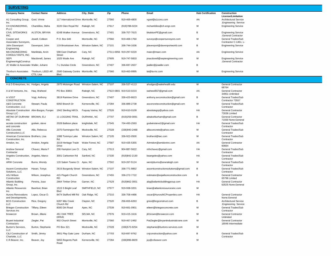
SURVEYING
Company Name Contact Name Address City, State Zip Phone Email Hub Certification Construction
License/Limitation
A1 Consulting Group,
Inc.
Goel, Vinnie 117 International Drive Morrisville, NC 27560 919-469-4800 [email protected] AA Architectural Service
;Engineering Service
;General Contractor CH ENGINEERING,
PLLC
Chambliss, Maha 3220 Glen Royal Rd Raleigh, NC 27617 (919)788-0224 [email protected] W Engineering Service
CIVIL SITEWORKS
INC.
ALSTON, BRYAN 624B Walker Avenue Greensboro, NC 27401 336-707-7615 [email protected] B Engineering Service
;General Contractor
72867 UnlimitedCooper and
Associates Surveyors,
P.A.
Jewell, Colleen P.O. Box 640 Morrisville, NC 27560 919-469-1760 [email protected] W General Trades/Sub
Contractor C-1461, L-
4501 John Davenport
Engineering
Davenport, John 119 Brookstown Ave. Winston-Salem, NC 27101 336-744-1636 [email protected] B Engineering Service
MA ENGINEERING
CONSULTANTS, INC.
Maniktala, Arvin 598 East Chatham
Street
Cary, NC 27511-6956 919-297-0220 [email protected] AA Engineering Service
SEPI
Engineering&Construc
tion
Macdonell, James 1025 Wade Ave Raleigh, NC 27605 919-747-5833 [email protected] W Engineering Service
;General Contractor
NoneJC Waller & Associates, PCWaller, Juhann 7-L Dundas Circle Greensboro, NC 27407 336-697-2637 [email protected] B
Thorburn Associates
Inc
Thorburn, LEED AP,
CTS, Lisa
2500 Gateway Centre
Blvd.
Morrisville, NC 27560 919-463-9995 [email protected] W Engineering Service
CONCRETE
A & D Enterprises, Inc. Hodges, Angela 2975 Motsinger Road Winston-Salem, NC 27107 336-537-4113 [email protected] W General Contractor
68764
Limited;General A & M Ventures, Inc. Haq, Waheed PO Box 30801 Raleigh, NC 27622-0801 919-510-0223 [email protected] AA General Contractor
34951 Unlimited
A VOGT
CONSTRUCTION
Vogt, Anthony 3819 Raintree Drive Greensboro, NC 27407 336-420-8623 [email protected] B General Trades/Sub
Contractor 73557
A&S Concrete
Construction, LLC
Stewart, Paula 6050 Branch Dr Kernersville, NC 27284 336-889-2738 [email protected] W General Trades/Sub
Contractor
Absolute Construction
Group LLC
Alim-Burgos, Furqan 1942 Sterling Hill Dr. Fuquay Varina, NC 27526 919-610-0109 [email protected] HA General Contractor
73036 Limited
ABTAK OF DURHAM
INC
BROWN, ELI 11 LOGGING TRAIL DURHAM,, NC 27707 (919)259-0091 [email protected] B General Contractor
71930 None;General
Trades/Sub acosta construction
and concrete
godwin, steve 2028 Ballston place knightdale, NC 27545 704-493-2593 [email protected] HA General Trades/Sub
Contractor
Allis Concrete
Construction,LLC
Allis, Rebecca 2070 Farmington Rd. Mocksville, NC 27028 (336)940-2468 [email protected] W General Trades/Sub
Contractor
American Cornerstone
Construction, Inc.
Brothers, Lisa 1088 Tommys Lake
Rd.
Winston Salem, NC 27105 336-922-0500 [email protected] W General Trades/Sub
Contractor
Amidon, Inc. Amidon, Angela 3319 Heritage Trade
Drive
Wake Forest, NC 27587 919-435-5355 [email protected] AA General Contractor
60664
Unlimited;General Andrew General
Contractor
Company,Inc
Chavez, Maria F 206 Hampton Lee Ct Cary, NC 27513 904-887-5622 [email protected] HA General Trades/Sub
Contractor
Angeles Construction,
Inc.
Angeles, Marco 3001 Carbonton Rd Sanford, NC 27330 (919)842-2130 [email protected] HA General Trades/Sub
Contractor
ARW Concrete Burns, Wendy 120 Salem Towne Ct Apex, NC 27502 919-267-5124 [email protected] W General Trades/Sub
Contractor
Ascent Construction
Solutions, LLC
Hasan, Tonya 2615 Burgandy Street Winston-Salem, NC 27107 336-771-9852 [email protected] B General Trades/Sub
Contractor
ASJ Wilson
Construction
Wilson, Josephus 415 Pisgah Church
RD
Greensboro, NC 27455 336-272-7722 [email protected] B General Contractor
65796 Limited
Atlantic Building
Group, Inc.
Pereira, Joao 2664 Timber Drive Garner, NC 27529 (919)662-3001 [email protected] HA General Contractor
63525 None;General
Trades/Sub Atlantic Resources
Inc.
Barefoot, Brian 1515 S Bright Leaf
Blvd
SMITHFIELD, NC 27577 919-938-3201 [email protected] W
Aurora Renovations
and Developments,
LLC
Lopez, Oscar D. 8474 Stafford Mill Rd Oak Ridge, NC 27310 336-708-4486 [email protected] HA General Contractor
None;General
Trades/Sub BCG Construction
LLC
Rice, Gregory 6287 little Creek
Church Rd
Clayton, NC 27520 256-655-6263 [email protected] B Architectural Service
;Engineering Service
;General Trades/Sub Briegan Construction
Services Inc
Tiffany, Eileen 8000 Dirt Road Apex, NC 27539 919-661-0901 [email protected] W General Trades/Sub
Contractor
browecon Brown, Jillane 451 OAK TREE
DRIVE
SELMA, NC 27576 919-415-1616 [email protected] W General Contractor
Unlimited
Bryant Industrial
Contractors
Ziegler, Pat 902 Church Street Morrisville, NC 27560 919-467-2492 [email protected] W General Contractor
18046 Intermediate
Burton's Services,
LLC
Burton, Stephanie PO Box 321 Mocksville, NC 27028 (336)575-9254 [email protected] W
C&J Construction of
Charlotte, LLC
Smith, Jimmy 3601 Play Gate Lane Durham, NC 27703 919-697-9762 [email protected] B General Trades/Sub
Contractor
C.R.Beaver, Inc. Beaver, Joy 5655 Regents Park
Road
Kernersville, NC 27284 (336)996-8829 [email protected] W

C2 Contractors, LLC Lamberth, Cornelious 405 Banner Avenue GREENSBORO, NC 27401 (336)379-8806 [email protected] B Electrical Contractor
;General Contractor
64914 Cadet Construction
Company
Dillahunt, Jr, Jimmy 6300 Chapel Hill Road Raleigh, NC 27607 919-758-8161 [email protected] B General Contractor
73807
Unlimited;General CALLIS
CONTRACTORS,
INC.
Callis, Jesse 1306 Broad Street Durham, NC 27705-3533 919-416-6191 [email protected] B General Contractor
59167 None;General
Trades/Sub Carolina Construction
Works Inc
Evans, Ronald 1305 E. Millbrook Rd Raleigh, NC 27609 919-427-1403 [email protected] B
Central Concrete of
N.C., Inc.
Sousa, Rui 4700 Trademark Drive Raleigh, NC 27610 919-467-5547 [email protected] HA General Trades/Sub
Contractor
Certified Concrete
Construction, Inc.
Sousa, Johnny 8700 Fleet Service Dr Raleigh, NC 27617 919-781-5575 [email protected] HA General Trades/Sub
Contractor
CIC Construction
Group USA, LLC
Sucre, Gilberto 5540 Centerview
Drive
Raleigh, NC 27606 919-297-2957 [email protected] HA General Contractor
77100 Unlimited
Cinda Corporation Cobb, Virgil 1922 MARTIN
LUTHER KING
JR.DR.
WINSTON SALEM,
NC
27107 704-746-7474 [email protected] B
CIVIL SITEWORKS
INC.
ALSTON, BRYAN 624B Walker Avenue Greensboro, NC 27401 336-707-7615 [email protected] B Engineering Service
;General Contractor
72867 UnlimitedClement Construction
Corporation
Clement Sr., Phillip 3735 Beeson Dairy
Rd.
Winston Salem, NC 27105 (336)661-2488 [email protected] B General Trades/Sub
Contractor 67844
Concrete Solutions by
Jimmy Hickman and
Hickman, James PO box 65 doral dr tobaccoville, NC 27050 336-782-1968 [email protected] B General Trades/Sub
Contractor
Construction
Concepts and Design
Inc.
McClain, Clifford 1922 S. Martin Luther
King Jr. Dr
Winston Salem, NC 27107 336-488-7112 [email protected] B Architectural Service
;Engineering Service
;General Contractor Cortez LLC Heck, Marinette 3426 Balfour East Durham, NC 27713 919-248-4444 [email protected] B General Contractor
None;General
Trades/Sub Cruz Brothers
Concrete,Inc.
Cruz, Maria 1572 Payne Road Lot
#75
Graham, NC 27253 (336)376-0787 [email protected] HA General Trades/Sub
Contractor
Cruz Concrete
Experts NC, LLC.
Moreno, Julie 8524 Six Forks Road Raleigh, NC 27615 919-803-3730 [email protected] HA General Trades/Sub
Contractor
Crystal Blu Pressure
Washing LLC
ford, tyrone 1113 taos trail RALEIGH, NC 27603 919-438-6690 [email protected] B
davidson construction Small, tony 208 gibson lane Clayton, NC 27520 (919)550-3485 [email protected] B General Contractor
63308 Limited
DayeCo Construction
LLC
Daye, Thomas 4100 Five Oaks Drive
#20
Durham, NC 27707 919-724-8111 [email protected] B General Contractor
None;General
Trades/Sub Double R Concrete
Finishing
Williams, Randy L. 6917 Windover Drive Durham, NC 27712 (919)477-3009 [email protected] B
DreamBuilt
Construction, Inc.
Thurmond, Carolyn 105 Seldom Farm
Lane
Advance, NC 27006-8775 336-940-3852 [email protected] W General Contractor
75480 Unlimited
DWG Property
Services Co LLC
Simms, Lisa 400 W. Main Street Durham, NC 27701 919-794-5948 [email protected] B General Trades/Sub
Contractor
Estrello Construction
Group, LLC
Estrello, Miguel 56 Needham Lane Clayton, NC 27527 919-802-2761 [email protected] HA General Contractor
79308
Limited;General Evans Construction
Services
Evans, William 120 Kingston Ct. Clayton, NC 27527 919-333-6494 [email protected] B General Contractor
71973 Limited
FEMCO Construction
LLC
Burkart, Lindsay 7302 Cessna Drive Greensboro, NC 27409 (336)669-1352 [email protected] W General Contractor
70215 Unlimited
Forsyth Ready Mix,
Inc.
Speer, Annie PO Box 95 Rural Hall, NC 27045 336-969-0446 [email protected] W
Franco Masonry
Concrete INC
Romero, Franco 4700 Forestville rd Raleigh, NC 27616 919-255-0331 [email protected] HA General Trades/Sub
Contractor
Giant Development,
Inc
Crabtree, Johanna 509 Pylon Dr Raleigh, NC 27606 919-521-0594 [email protected] W
Gilgeours
Construction
Corporation
Gilgeours, Lisa 2500 E. Bessemer
Ave Ste A
Greensboro, NC 27405 336-558-6572 [email protected] B General Trades/Sub
Contractor
Golden City
Construction, Inc.
Munn, Quintin 410 South Driver St Durham, NC 27703 919-358-3604 [email protected] AA General Contractor
77534 Limited
Goliath Construction,
LLC
Fonville, Eric 14460 Falls of Neuse
Rd
Raleigh, NC 27614 919-896-9909 [email protected] B General Contractor
70521
Limited;General Goulding Construction
Inc.
goulding, rhonda PO BOX 136 Clayton, NC 27528 (919)763-9151 [email protected] W General Contractor
56831 Limited
Harris Concrete and
Construction, Inc
harris, sean 1931 allyson ave greensboro, NC 27405 (336)362-3178 [email protected] B General Trades/Sub
Contractor
Hinton Concrete, LLC Hinton, Walter 2430
Baileyscrossroad Rd
Coats, NC 27521 919-868-2962 [email protected] B General Trades/Sub
Contractor
Holt Brothers
Construction LLC
Gilmore, Patrice 421 Fayetteville Street Raleigh, NC 27601 919-787-1981 [email protected] B General Contractor
71120 Unlimited
Honducom Concrete,
Inc.
Suazo, Ramon P.O. Box 14968 Raleigh, NC 27620 (919)662-0388 [email protected] HA General Trades/Sub
Contractor
Horus Construction of
NC, Inc.
Scott, Marcus 11550 Common Oaks
Dr
Raleigh, NC 27614 336-339-3939 [email protected] B General Contractor
68185 None
Incline Construction,
Inc.
Pope, Robert 2503 East Pettigrew
Street
Durham, NC 27703 919-598-8006 [email protected] W General Contractor
55896 Intermediate

IQ Contracting, LLC Nunez, Robert P. O. Box 6069 Raleigh, NC 27628 (919)832-5111 [email protected] HA General Contractor
60795
Limited;General J. S. Mention
Construction, LLC
Mention, Jamal 1451 South Elm-
Eugene Street
Greensboro, NC 27406 336-373-1911 [email protected] B General Contractor
70689 None
JC Concrete
Construction, LLC
Corona, Josue P.O. Box 613 Pinnacle, NC 27043 336-699-6270 [email protected] HA General Trades/Sub
Contractor
JCG & Associates
LLC
Greene, John 612 Martin St Greensboro, NC 27406 336-763-7951 [email protected] B General Contractor
67490 Limited
JDB Contracting, LLC West, Michele 6109 Bramlette Court Fuquay Varina, NC 27526 919-455-5749 [email protected] W
Jordan's Mill
Construction Inc
Shea, Brittany 3977 Jordans Mill Ct High Point, NC 27265 336-687-2879 [email protected] W General Contractor
None
KEA Contracting, Inc. Askew, Kathryn 6612 Six Forks Suite
203
Raleigh, NC 27615 919-847-3701 [email protected] W General Contractor
73213
Unlimited;General Kirk & Pam
Construction Inc
Keranen, Pamela PO Box 340 Sophia, NC 27350 (336)431-0255 [email protected] W General Trades/Sub
Contractor
Lacayo Concrete
Flatwork, Inc
Lacayo, Ernest 246 River Trace Drive Rougemont, NC 27572 336-364-2252 [email protected] HA
Magnolia Construction
LLC
Cook, Monnette 514 S. Stratford Road Winston-Salem, NC 27103 336-724-7202 [email protected] D General Contractor
46428 None;General
Trades/Sub Martinez Company Brown, Keith 342 Fleming Drive Durham, NC 27712 (919)724-2611 [email protected] HA General Contractor
68806
Unlimited;General Martinez Construction
NC LLC
Perez Martinez,
Ismael
1052 Heather ln Wake Forest, NC 27587 919-600-1723 [email protected] HA General Trades/Sub
Contractor
Mayes Landscaping &
Concrete Inc.
Mayes, Ricky PO Box 984 Winston Salem, NC 27102 336-682-3845 [email protected] B General Contractor
62266
Limited;General McClure and
Associates Constru
McClure, Lesle 6201 Remington Lake
Dr.
Raleigh, NC 27616 919-878-8006 [email protected] W General Contractor
42632 Unlimited
MCNOC, Inc. McCoy, Mathew 2664 Timber Dr STE
345
Garner, NC 27529 919-772-6159 [email protected] B Electrical Contractor
;General Contractor
None;General Minority Trade
Services
Lopez, Solamon 1710 hamlin road Durham, NC 27704 919-201-7683 [email protected] HA Architectural Service
;General Trades/Sub
Contractor Muter Construction
LLC
Muter, Beth 100 N. Arendell Ave. Zebulon, NC 27597 919-404-8330 [email protected] W General Contractor
73095 None;General
Trades/Sub Nall Construction Co Nall, Elizabeth PO Box 103 Gibsonville, NC 27249 336-707-9735 [email protected] W General Contractor
73967 Limited
nc hardscape inc. urena, juan 3912 battleground ave
suite 112- 151
greensboro, NC 27410 336-455-2034 [email protected] HA General Trades/Sub
Contractor
Nehemiah Builders,
Inc
EVANS, DONALD 1305 EAST
MILLBROOK ROAD
RALEIGH, NC 27609 (919)877-0505 [email protected] B General Contractor
55902
Unlimited;General Nesmith Construction,
LLC
McNeal, Maurice 1212 Portland Street Greensboro, NC 27403 336-202-1385 [email protected] B General Contractor
72826 Unlimited
New Shine Concrete Felisberto, Rigelma 4223 Glen Summit Ct Apex, NC 27539 919-772-5127 [email protected] HA General Trades/Sub
Contractor 96637
O.U.Chavis
Contracting Corp.
Chavis, Odysseus P.O. Box 36199 Greensboro, NC 27406 (336)378-0072 [email protected] B General Contractor
47772
Unlimited;General PCM Construction,
Inc.
Pena, Juan 133 Bluff Street Jonesville, NC 28642 (336)527-4536 [email protected] HA General Trades/Sub
Contractor
PGA Construction Inc Reeser, Kelli 9 Crosswinds Estates
Dr.
Pittsboro, NC 27312 919-610-1260 [email protected] W General Contractor
67249 Limited
Praylor Construction
Company
Praylor, Michael 4005 Pond Valley
Court
Mc Leansville, NC 27301 336-471-8987 [email protected] B General Contractor
64702 Limited
PRO-TECH
CONSTRUCTION INC
Wilkerson, Linda 7429 ACC Blvd, Suite
109
Raleigh, NC 27617-8401 919-848-9035 [email protected] W General Contractor
28732
Limited;General Pull Construction
Company, Inc
Frazelle, Kenneth PO Box 16725 Greensboro, NC 27416 336-274-6813 [email protected] B General Contractor
34046 Intermediate
QST,Inc Fleming, Warren 157 Hickory Street North Cooleemee, NC 20874 301-916-4522 [email protected] B
R&W Construction of
NC Inc.
Robinson, Charlotte 132 S Main Street Warrenton, NC 27589 910-860-8898 [email protected] B Architectural Service
;Engineering Service
RBS Grading &
Excavating, INC.
Jones, Richard 4206 Holder Rd. Durham, NC 27703 919-596-5669 [email protected] AI General Contractor
38638
Unlimited;General Reach Construction
Group, LLC
Martin, Brandon 7501 Falls of the
Neuse Rd
Raleigh, NC 27615 919-842-4380 [email protected] B General Contractor
73359
Unlimited;General Reddrick Masonry Reddrick, Rueben 701 Felicia Street Durham, NC 27704 919-477-8297 [email protected] B General Trades/Sub
Contractor
RFI Construction LLC Burrows, Rupert 1451 S. Elm Eugene
St.
Greensboro, NC 27406 336-510-0441 [email protected] B General Contractor
None;General
Trades/Sub Roadrunner Concrete
LLC
Vasquez, Ossiris 5223 LLOYD HILL LN GRAHAM, NC 27253 336-675-6238 [email protected] HA General Trades/Sub
Contractor
Royals Contracting,
Inc.
Royals, Pat PO Box 91359 Raleigh, NC 27675 919-847-3811 [email protected] W General Contractor
59612 Unlimited
S and J of Raleigh Spears, Shawn 3235 Mclean Chapel
Church RD
bunnlevel, NC 28323 (919)669-9462 [email protected] B General Contractor
55247
Limited;General

SAL
CONSTRUCTION CO.
Shah, Dinesh 1517 Old Apex Rd. Cary, NC 27513 919-460-1817 [email protected] AA Engineering Service
;General Contractor
24633 UnlimitedSelect Concrete
Construction LLC
Irwin, Mary 346 Elizabeth Brady
Rd
Hillsborough, NC 27278 919-459-7235 [email protected] W General Trades/Sub
Contractor
Sinclair Contracting,
LLC
Lennon, Walter Post Office Box 1495 Wake Forest, NC 27588 919-522-8285 [email protected] B General Contractor
72293 Limited
Skyrock Construction
LLC
Manso, Nana 1000 Old Milburnie Rd
Suite A
Raleigh, NC 27604 919-266-2446 [email protected] B General Contractor
68111
Limited;General SLM Construction
Company Inc.
McLeod, Sandra 513 White Smith Road Pittsboro, NC 27312 (919)663-0968 [email protected] W General Trades/Sub
Contractor
Smart Contracting,
Inc.
Hampton, Joe 1516 Miriam Ave Garner, NC 27529 919-633-6409 [email protected] B General Contractor
None;General
Trades/Sub SRS Inc. Edwards, Monte PO Box 38771 Greensboro, NC 27438 336-580-9000 [email protected] B General Contractor
64370 None
Steve & Sons
Construction
Esteves, Manny 1529 Sophia Ridge
Drive
Fuquay Varina, NC 27526 919-625-8242 [email protected] HA
Stoney Creek
Construction Inc.
DeBord, Dorian 6510 Brookstone
Drive
Whitsett, NC 27377 336-639-6082 [email protected] W General Contractor
69303
Limited;General STRUCTURE
BUILDING
COMPANY, INC.
Farrar, Jonathan PO Box 13503 Durham, NC 27709 919-730-6821 [email protected] B General Contractor
47994
Unlimited;General SUMMA GENERAL
CONTRACTORS, LLC
VERGARA,
ALFONSO
108 PRESTON PINES
DR
CARY, NC 27513 (919)215-8068 [email protected] HA Engineering Service
;General Contractor
64373 LimitedSunrise Repair and
Construction, Inc.
Estrera, Rolando P.O. Box 1616 Jamestown, NC 27282 336-307-5592 [email protected] AA General Contractor
74637 Limited
SVG Concrete
Services Inc.
VERASTEGUI,
SERGIO
PO BOX 4308 CARY, NC 27519 (919)567-0044 [email protected] HA General Trades/Sub
Contractor
T & M Construction
Group LLC
Mapp, Terome 1100 Lake Front Dr.
apt. J
Raleigh, NC 27613 336-404-8640 [email protected] B General Contractor
51912 Limited
Triangle Concrete and
Contracting, Inc.
Kuley, Barbara 7002 Scarlet Lane Garner, NC 27529 (919)662-0406 [email protected] W General Trades/Sub
Contractor
tsimmonsbackhoecon
crete
simmons, theodore 7507 doggett rd brownsummitt, NC 27214 (336)382-1167 [email protected] B
W. E. GARRISON CO Garrison, Colleen 5820 Fayetteville
Road
Raleigh, NC 27603 919-772-4144 [email protected] W General Contractor
None;General
Trades/Sub WHITLEY
CONTRACTING INC
WHITLEY, BRANDY 5735 BROGDEN RD SMITHFIELD, NC 27577 919-524-1703 [email protected] W General Contractor
71585 Limited
SIGNAGE
AKS Gifts &
Promotionals LLC
Lindsay, Andrew 4465 Kimball Lane Winston Salem, NC 27105 336-744-9542 [email protected] B
AMERICAN SAFETY
PRODUCTS
Arrington Jr., Warren
H.
3200 Glen Royal Rd Raleigh, NC 27617 919-571-7822 [email protected] B
AOA Signs Inc. Kay, Joy 206 EAST HEMLOCK
ST.
YADKINVILLE, NC 27055 336-679-3344 [email protected] W
Atlantic Resources
Inc.
Barefoot, Brian 1515 S Bright Leaf
Blvd
SMITHFIELD, NC 27577 919-938-3201 [email protected] W
Bear Co. & Signs &
Lighting, I
VanDerGoot, Rebecca 2618-A Battleground
Avenue #276
Greensboro, NC 27408 336-854-1023 [email protected] W
Brandilly Marketing &
Creative
Washington, Kemah 615 W. Hargett Street Raleigh, NC 27603 919-278-7896 [email protected] B
Corum Signs, Inc. Corum, Beverly 104 Tandy Court Jamestown, NC 27282 336-886-2212 [email protected] W
Fastsigns Riddle, Angela 1305 N. Main St. High Point, NC 27262 336-887-2923 [email protected] W
Hargett Supply, Inc. Hargett, Kathy 6845 Spencer Dixon
Rd.
Greensboro, NC 27455 336-580-2606 [email protected] W
Innovative Signs &
Graphics, LLC
Pierce, Doug 1145A St Mark's
Chruch Road
Burlington, NC 27215 336-538-1825 [email protected] W
Mebane Distributing
Company LLC
Denton, Meg 1508 Cedar Pointe
Drive
Mebane, NC 27302 336-263-8337 [email protected] W
Nature Graphics Beazley, Lea 207 Horseshoe Bend
Road
Littleton, NC 27850 704-880-8026 [email protected] W
Precision Signs Inc. Peach, Laurie 6601 Hillsborough
Street
Raleigh, NC 27606 919-615-0979 [email protected] W
Rodney's Custom Cut
Sign Co.
Dalpe, Tayler 600 Irving Parkway Holly Springs, NC 27540 919-362-9669 [email protected] W
S J DIGITAL
SERVICES , LLC
OROSCO, SOPHIA 2110 A CHESHIRE
WAY
Greensboro, NC 27405 336-852-7141 [email protected] HA
Signs Now Lewis, Cat 2424 Atlantic Ave. Raleigh, NC 27604 919-546-0006 [email protected] W
Stay Alert Safety
Services
Babcock, Melissa 272 Clayton Forest
Road
Kernersville, NC 27284 336-993-2828 [email protected] W
Steed's Service
Company, Inc.
Steed, Dale 109 Pineywood Street Thomasville, NC 27360-3434 336-475-0745 [email protected] D

TES ENGRAVING &
SIGNS INC
WILLIAMS, JR.,
BENNIE
620 Motor Rd Winston Salem, NC 27105 336-723-5816 [email protected] B
the trac company Rawley, Madeline 2320 Spruce Shadows
Lane
raleigh, NC 27614 336-309-4249 [email protected] B
TraSam Industries Snipes, Tracy PO Box 103 Whitsett, NC 27377 336-512-0536 [email protected] B
PAINT
STRIPPINGCALLIS
CONTRACTORS,
INC.
Callis, Jesse 1306 Broad Street Durham, NC 27705-3533 919-416-6191 [email protected] B General Contractor
59167 None;General
Trades/Sub Construction
Concepts and Design
Inc.
McClain, Clifford 1922 S. Martin Luther
King Jr. Dr
Winston Salem, NC 27107 336-488-7112 [email protected] B Architectural Service
;Engineering Service
;General Contractor Creative Design and
Construction,Inc.
Gupton, Samie PO Box 306 Tobaccoville, NC 27050 (336)983-7048 [email protected] W Architectural Service
;Engineering Service
;General Contractor DayeCo Construction
LLC
Daye, Thomas 4100 Five Oaks Drive
#20
Durham, NC 27707 919-724-8111 [email protected] B General Contractor
None;General
Trades/Sub Nehemiah Builders,
Inc
EVANS, DONALD 1305 EAST
MILLBROOK ROAD
RALEIGH, NC 27609 (919)877-0505 [email protected] B General Contractor
55902
Unlimited;General Praylor Construction
Company
Praylor, Michael 4005 Pond Valley
Court
Mc Leansville, NC 27301 336-471-8987 [email protected] B General Contractor
64702 Limited
LMJ Pavement
Marking,LLC
Calton, Kristin 76 oak Fern lane Willow Spring, NC 27592 910-322-6749 [email protected] W
T & M Construction
Group LLC
Mapp, Terome 1100 Lake Front Dr.
apt. J
Raleigh, NC 27613 336-404-8640 [email protected] B General Contractor
51912 Limited
The Smith Group-
CLWLLC
Smith, Darius 3825 Clara Lane Winston Salem, NC 27105 336-347-9847 [email protected] B Engineering Service
;General Contractor
Unlimited;General ASPHALT
Asphalt Services on
Demand, Inc.
Daniels, Amber 959 Short Journey Rd. Smithfield, NC 27577 919-209-0020 [email protected] W
YADKIN VALLEY
PAVING, INC.
Ferguson, Gina 121 Cloverleaf Drive Winston Salem, NC 27103 336-765-7900 [email protected] W
MASONRY
A & M Ventures, Inc. Haq, Waheed PO Box 30801 Raleigh, NC 27622-0801 919-510-0223 [email protected] AA General Contractor
34951 Unlimited
Active Construction
Services LLC
stevons, shante 631 United Drive
Suite# 100-B
DURHAM, NC 27713 (919)206-4440 [email protected] B General Trades/Sub
Contractor
ASG Construction
Services, LLC
Stewart, Svetlana P. O. Box 112 Brown Summit, NC 27214 336-458-6764 [email protected] W
Atlantic Building
Group, Inc.
Pereira, Joao 2664 Timber Drive Garner, NC 27529 (919)662-3001 [email protected] HA General Contractor
63525 None;General
Trades/Sub Boone Masonry, Inc. Boone, Lori 2430 S NC 87 Graham, NC 27253 336-228-0615 [email protected] W General Trades/Sub
Contractor
Brodie
Contractors,Inc.
Brodie, Calvin 3901 Computer Dr. Raleigh, NC 27609 (919)782-2482 [email protected] B General Contractor
30671
Unlimited;General Bryant Industrial
Contractors
Ziegler, Pat 902 Church Street Morrisville, NC 27560 919-467-2492 [email protected] W General Contractor
18046 Intermediate
CRQ MASONRY INC. QUINTERO, CARLOS P.O. BOX 40814 RALEIGH, NC 27629 919-553-8261 [email protected] HA General Trades/Sub
Contractor
Carolina Construction
Works Inc
Evans, Ronald 1305 E. Millbrook Rd Raleigh, NC 27609 919-427-1403 [email protected] B
Cleve Wagstaff Stone
Masonry LLC
Wagstaff, Cleve 309 Wagstaff Road Roxboro, NC 27574 (336)599-6080 [email protected] W General Contractor
23847
Limited;General Cortez LLC Heck, Marinette 3426 Balfour East Durham, NC 27713 919-248-4444 [email protected] B General Contractor
None;General
Trades/Sub CRQ MASONRY INC. QUINTERO, CARLOS P.O. BOX 40814 RALEIGH, NC 27629 919-553-8261 [email protected] HA General Trades/Sub
Contractor
davidson construction Small, tony 208 gibson lane Clayton, NC 27520 (919)550-3485 [email protected] B General Contractor
63308 Limited
DreamBuilt
Construction, Inc.
Thurmond, Carolyn 105 Seldom Farm
Lane
Advance, NC 27006-8775 336-940-3852 [email protected] W General Contractor
75480 Unlimited
Eddie Land, Inc. Land, Nancy P. O. Box 334 Browns Summit, NC 27214 (336)656-1270 [email protected] W General Trades/Sub
Contractor
ETC Contractors, LLC Esteves, Liz 3829 Opportunity
Lane
Raleigh, NC 27603 (919)772-4114 [email protected] HA General Trades/Sub
Contractor
Evans Construction
Services
Evans, William 120 Kingston Ct. Clayton, NC 27527 919-333-6494 [email protected] B General Contractor
71973 Limited
Franco Masonry
Concrete INC
Romero, Franco 4700 Forestville rd Raleigh, NC 27616 919-255-0331 [email protected] HA General Trades/Sub
Contractor
Fred Adams Paving
Co., Inc.
Adams, Fred P.O. Box 227 Morrisville, NC 27560 919-468-9101 [email protected] W General Trades/Sub
Contractor
Gilgeours
Construction
Corporation
Gilgeours, Lisa 2500 E. Bessemer
Ave Ste A
Greensboro, NC 27405 336-558-6572 [email protected] B General Trades/Sub
Contractor

Holt Brothers
Construction LLC
Gilmore, Patrice 421 Fayetteville Street Raleigh, NC 27601 919-787-1981 [email protected] B General Contractor
71120 Unlimited
Home Improvements
Orellana, INC
Orellana, Angel A. 602 Pleasant Drive Durham, NC 27703 919-280-1982 [email protected] HA General Contractor
None
Horus Construction of
NC, Inc.
Robins, Sonya 11550 Common Oaks
Drive
Raleigh, NC 27401 (877)898-6879 [email protected] B General Contractor
2705 132156A None
Horus Construction of
NC, Inc.
Scott, Marcus 11550 Common Oaks
Dr
Raleigh, NC 27614 336-339-3939 [email protected] B General Contractor
68185 None
Incline Construction,
Inc.
Pope, Robert 2503 East Pettigrew
Street
Durham, NC 27703 919-598-8006 [email protected] W General Contractor
55896 Intermediate
JCG & Associates
LLC
Greene, John 612 Martin St Greensboro, NC 27406 336-763-7951 [email protected] B General Contractor
67490 Limited
JCG & Associates
LLC
Greene, john 612 Martin St. Greensboro, NC 27406 336-763-7951 [email protected] B General Contractor
67490
Limited;General Joe Sutton Company Sutton, Joseph 711 Martin Street Greensboro, NC 27406 336-215-0244 [email protected] B General Trades/Sub
Contractor
Johnson & Johnson
Masonry
Johnson, Cathey 412 Berryman St. Greensboro, NC 27405 (336)288-8813 [email protected] B General Trades/Sub
Contractor
Johnson & Johnson
Masonry
Johnson, NJ 412 Berryman St. Greensboro, NC 27405 (336)288-8813 [email protected] B General Trades/Sub
Contractor
Jordan's Mill
Construction Inc
Shea, Brittany 3977 Jordans Mill Ct High Point, NC 27265 336-687-2879 [email protected] W General Contractor
None
K & R Building
Solution
Desmore, Kevin P.O. Box 1148 Chapel Hill, NC 27514 919-869-7353 [email protected] B General Contractor
Limited
KEA Contracting, Inc. Askew, Kathryn 6612 Six Forks Suite
203
Raleigh, NC 27615 919-847-3701 [email protected] W General Contractor
73213
Unlimited;General LL Masonry Inc Romero, Lorena PO Box 11902 Winston Salem, NC 27116 (336)744-0263 [email protected] HA General Trades/Sub
Contractor
Magnolia Construction
LLC
Cook, Monnette 514 S. Stratford Road Winston-Salem, NC 27103 336-724-7202 [email protected] D General Contractor
46428 None;General
Trades/Sub Martins Masonry Inc Martin, Wayne 4401 Grubbs Rd. Walkertown, NC 27051 336-595-8882 [email protected] B General Trades/Sub
Contractor
MASONRY
MANAGEMENT, INC.
TROUTMAN, KATHY P. O. Box 1573 LEXINGTON, NC 27293 336-238-1049 [email protected] W
McClure and
Associates Constru
McClure, Lesle 6201 Remington Lake
Dr.
Raleigh, NC 27616 919-878-8006 [email protected] W General Contractor
42632 Unlimited
Minority Trade
Services
Lopez, Solamon 1710 hamlin road Durham, NC 27704 919-201-7683 [email protected] HA Architectural Service
;General Trades/Sub
Contractor Muter Construction
LLC
Muter, Beth 100 N. Arendell Ave. Zebulon, NC 27597 919-404-8330 [email protected] W General Contractor
73095 None;General
Trades/Sub nc hardscape inc. urena, juan 3912 battleground ave
suite 112- 151
greensboro, NC 27410 336-455-2034 [email protected] HA General Trades/Sub
Contractor
Nehemiah Builders,
Inc
EVANS, DONALD 1305 EAST
MILLBROOK ROAD
RALEIGH, NC 27609 (919)877-0505 [email protected] B General Contractor
55902
Unlimited;General Nesmith Construction,
LLC
McNeal, Maurice 1212 Portland Street Greensboro, NC 27403 336-202-1385 [email protected] B General Contractor
72826 Unlimited
O.U.Chavis
Contracting Corp.
Chavis, Odysseus P.O. Box 36199 Greensboro, NC 27406 (336)378-0072 [email protected] B General Contractor
47772
Unlimited;General Rambo Masonry Gomez, Jose 417 Burke Street Kernersville, NC 27284 336-345-4445 [email protected] HA General Trades/Sub
Contractor
Reddrick Masonry Reddrick, Rueben 701 Felicia Street Durham, NC 27704 919-477-8297 [email protected] B General Trades/Sub
Contractor
RFI Construction LLC Burrows, Rupert 1451 S. Elm Eugene
St.
Greensboro, NC 27406 336-510-0441 [email protected] B General Contractor
None;General
Trades/Sub S and J of Raleigh Spears, Shawn 3235 Mclean Chapel
Church RD
bunnlevel, NC 28323 (919)669-9462 [email protected] B General Contractor
55247
Limited;General SAL
CONSTRUCTION CO.
Shah, Dinesh 1517 Old Apex Rd. Cary, NC 27513 919-460-1817 [email protected] AA Engineering Service
;General Contractor
24633 UnlimitedSGS Contracting, LLC Gattis II, Jonathan 4407 Hopson Road Morrisville, NC 27560 919-391-8515 [email protected] B General Contractor
74326 Limited
Smart Contracting,
Inc.
Hampton, Joe 1516 Miriam Ave Garner, NC 27529 919-633-6409 [email protected] B General Contractor
None;General
Trades/Sub Splendid Services dodson, kenneth P.O. Box 1134 Greensboro, NC 27402 (336)991-2509 [email protected] B General Trades/Sub
Contractor
Steve & Sons
Construction
Esteves, Manny 1529 Sophia Ridge
Drive
Fuquay Varina, NC 27526 919-625-8242 [email protected] HA
Stoney Creek
Construction Inc.
DeBord, Dorian 6510 Brookstone
Drive
Whitsett, NC 27377 336-639-6082 [email protected] W General Contractor
69303
Limited;General STRUCTURE
BUILDING
COMPANY, INC.
Farrar, Jonathan PO Box 13503 Durham, NC 27709 919-730-6821 [email protected] B General Contractor
47994
Unlimited;General SUMMA GENERAL
CONTRACTORS, LLC
VERGARA,
ALFONSO
108 PRESTON PINES
DR
CARY, NC 27513 (919)215-8068 [email protected] HA Engineering Service
;General Contractor
64373 LimitedSunrise Repair and
Construction, Inc.
Estrera, Rolando P.O. Box 1616 Jamestown, NC 27282 336-307-5592 [email protected] AA General Contractor
74637 Limited

T & M Construction
Group LLC
Mapp, Terome 1100 Lake Front Dr.
apt. J
Raleigh, NC 27613 336-404-8640 [email protected] B General Contractor
51912 Limited
The Masonry Co., Inc. Martinez, Jennifer 279 Shady Knoll Lane Mocksville, NC 27028 336-492-2685 [email protected] HA General Trades/Sub
Contractor
U&L Contractors, LLC Aguilar, Mr. 9660-138 Falls of
Neuse Rd.
Raleigh, NC 27615 919-427-4055 [email protected] HA General Trades/Sub
Contractor
William E. Smith
Masonry Inc.
Smith, Tiffany 1818 Marions Ford
Road
Chapel Hill, NC 27516 (919)321-1814 [email protected] B General Trades/Sub
Contractor
LANDSCAPING
Mayes Landscaping &
Concrete Inc.
Mayes, Ricky PO Box 984 Winston Salem, NC 27102 336-682-3845 [email protected] B General Contractor
62266
Limited;General B and B Triangle
Lawncare
Bond, Andre P.O. Box 25006 Durham, NC 27702 (919)423-1417 [email protected] B
jessie lane's
landscaping & trucking
inc
Friddle, Jessica PO Box 225 Summerfield, NC 27358 336-643-4948 [email protected] W
Hicks Landscape
Contractors
hicks, scott 6204 Robertson Pond
Rd
Wendell, NC 27591 919-366-0115 [email protected] D
Davis Site Services,
LLC
Davis, Allyson PO Box 37364 Raleigh, NC 27627 919-520-1696 [email protected] W General Trades/Sub
Contractor NCLC
#1064 Seal Brothers
Contracting, LLC
Seal, Mari 3618 W. Pine Street Mount Airy, NC 27030 336-786-2263 [email protected] W General Trades/Sub
Contractor
Southern Garden, Inc Lichtenstein, Russell P. O. Box 808, Apex,
NC 27502
Cary, NC 27519 919-362-1050 [email protected] W General Trades/Sub
Contractor Landsca
#CL0740 Southernscapes, Inc Roper, Roy 309 S Rogers Lane Raleigh, NC 27610 919-231-0099 [email protected] AA General Trades/Sub
Contractor Landscape
Contractor # 857 W Landscaping Cheek, Wallace 51 Allen Ln Henderson, NC 27536 252-915-5680 [email protected] B General Trades/Sub
Contractor
Transou and Son
Landscaping
Transou, Sherman 144 Cherryview Lane Winston Salem, NC 27105 336-782-3020 [email protected] B General Contractor
None
Triangle Landscape
supplies of
Mangum, Stacey 6300 Cornwalis Road Garner, NC 27529 919-553-1118 [email protected] W
STEEL
Alexis Steel LLC Lara, Mauro 1117 Corporation
Pkwy Ste 108
Raleigh, NC 27610 919-255-3373 [email protected] HA General Trades/Sub
Contractor
Best & Sons Iron
Erectors Inc
Best, Sheila 5103 Willow Bend
Road
Greensboro, NC 27406 (336)697-3883 [email protected] W General Trades/Sub
Contractor
Branagans Metal
Works LLC
Branagan, Edward 708 John st Clayton, NC 27520 919-210-4616 [email protected] B Engineering Service
;General Contractor
Limited;General C.R.Beaver, Inc. Beaver, Joy 5655 Regents Park
Road
Kernersville, NC 27284 (336)996-8829 [email protected] W
Carolina Guardrail,
LLC
Perkins, Carri PO BOX 879 Colfax, NC 27235 336-707-9971 [email protected] W General Trades/Sub
Contractor
Creative Design and
Construction,Inc.
Gupton, Samie PO Box 306 Tobaccoville, NC 27050 (336)983-7048 [email protected] W Architectural Service
;Engineering Service
;General Contractor Custom SheetMetal
Services, Inc
Lee, Peggy 5109 Neal Road Durham, NC 27705 919-282-1070 [email protected] W
Davidson Steel
Services, LLC
Whicker, Sheryl 11075 Old Highway 52 Winston-Salem, NC 27107 336-775-1234 [email protected] W
Flores Welding, Inc. Belhassen, Marielle 961 Palace Garden
Way
Raleigh, NC 27603 (919)838-1060 [email protected] HA
Freeman & Associates Freeman, Ruben 225 Tryon Rd., Ste.
105
Raleigh, NC 27603 919-779-9330 [email protected] B General Contractor
50040 Unlimited
Goulding Construction
Inc.
Goulding, Rhonda 1909 Hemlock Place Clayton, NC 27520 919-763-9151 [email protected] W General Contractor
56831 Limited
Shellste Metals, Inc. Workman, Michelle PO Box 1212 Apex, NC 27502 (919)367-9422 [email protected] W General Trades/Sub
Contractor
Holt Brothers
Construction LLC
Gilmore, Patrice 421 Fayetteville Street Raleigh, NC 27601 919-787-1981 [email protected] B General Contractor
71120 Unlimited
Junior's Drywall LLC Aguirre, Pedro 4808 Old Faison Road Knightdale, NC 27545 919-866-9292 [email protected] HA General Trades/Sub
Contractor
KCAD of North
Carolina Inc
Cox, Kevin 101 Woolard Way Apex, NC 27502 919-225-4472 [email protected] W
Metal Impressions,
Inc.
Sweeley, Renee PO Box 1425 Pittsboro, NC 27312 919-542-4655 [email protected] W General Contractor
74397 Limited
Phillips Iron Works Mah-Throndson,
Maryanne
4809 Auburn
Knightdale Rd.
Raleigh, NC 27610 919-615-1570 [email protected] W General Trades/Sub
Contractor
Quality & Precision
Fencing/welding
Quarterman, Mitchell 4010 old chapel hill
rd.apt1
Durham, NC 27707 (919)428-4391 [email protected] B General Trades/Sub
Contractor
200001868923 SAL
CONSTRUCTION CO.
Shah, Dinesh 1517 Old Apex Rd. Cary, NC 27513 919-460-1817 [email protected] AA Engineering Service
;General Contractor
24633 UnlimitedSchulz Iron Works,
Inc.
Schulz, Cindy 1620 Wolfpack Lane Raleigh, NC 27609 (919)981-6121 [email protected] W

Shellste Metals, Inc. Workman, Michelle PO Box 1212 Apex, NC 27502 (919)367-9422 [email protected] W General Trades/Sub
Contractor
steel city services McQueen, JD 1129 East Geer Street Durham, NC 27704 (919)698-2407 [email protected] B General Trades/Sub
Contractor
Structural Steel of
Carolina
Parnell, Michael 1720 Vargrave Street Winston Salem, NC 27107 336-354-4159 [email protected] W General Trades/Sub
Contractor
Triangle Insulation
Services,
Vaughan, lisa 903 East Trinity
Avenue, Suite 104
Durham, NC 27704 919-682-4300 [email protected] W General Trades/Sub
Contractor
Webb's Welding &
Services
Webb, Johnny 7636 Sam Hall Rd. Oxford, NC 27565 919-690-0867 [email protected] B General Trades/Sub
Contractor
ZAMARRIPA
BROTHERS
FRAMING, IN
ZAMARRIPA,
ADELFINO
5857 Farmwell Rd Raleigh, NC 27610-9274 919-723-6768 [email protected] HA General Contractor
None;General
Trades/Sub

APPENDIX C
CERTIFIED UNDERUTILIZED BUSINESS ENTERPRISE
(UBE) REPORTING FORMS
CONTRACT: ST-264

This page intentionally left blank

APPENDIX C
SMRPR 10/01/03
CITY OF DURHAM
SUBCONTRACTOR MONTHLY RECORD OF PAYMENT REPORT
THIS DOCUMENT MUST REFLECT ALL SUBCONTRACTORS & MUST BE SUBMITTED WITH MONTHLY INVOICE FOR PAYMENT
PROJECT NAME: 2018 Street Repairs and Repaving
CONTRACT#: ST-285
DATE FORM SUBMITTED:
WORK PERIOD ENDING:
COMPANY NAME: ADDRESS:
FEDERAL TAX ID#: CONTACT PERSON:
Subcontractor/Vendor ID (Street Address/Zip/Telephone)
Indicate
Ownership
Status
Description Of Work
Total
Sub-
Contract
Amount
Amount
Paid
For The
Period
Total Amount
Paid
To-Date
Percentage
Of
Work
Completed
Scheduled
Start
Date
Scheduled
End
Date
Total M/UBE Subcontracts Awarded/% $ % Total W/UBE Subcontracts Awarded/% $ %
Total M/UBE Dollars Paid-To-Date/% $ % Total W/UBE Dollars Paid-To-Date/% $ %
Total Non-Minority Subcontracts Awarded/% $ % Total Non-W/UBE Subcontracts Awarded/% $ %
Total Non-Minority Dollars Paid-To-Date/% $ % Total Non W/UBE Dollars Paid-To-Date/% $ %
The undersigned certifies that the information recorded above is correct, and that each of the representations set forth above is true. The undersigned further acknowledges that any misrepresentation
hereon may result in termination of contract and/or prosecution under applicable Federal and State laws concerning false statements and false claims.
Company Representative________________________________________ Title: _____________________________ Date: _________________

APPENDIX C
CITY OF DURHAM
Equal Business Opportunity Program
Final Subcontracting Report
THIS FORM MUST BE COMPLETED AND SUBMITTED TO THE PROJECT/CONTRACT ADMINISTRATOR
FOR SUBMITTAL TO THE EO/EA DEPARTMENT WITHIN FIFTEEN (15) DAYS AFTER FINAL INSPECTION
OF CONTRACT WORK.
Company Name: ___________________________________Project Name: ST-285: 2018 Street Repairs and Repaving
Address: _____________________________________________________________________________________________
Federal Tax ID#: ____________________________________ Date Submitted: ___________________________________
Date of Final Inspection: _____________________________ Total Final Contract Price: __________________________
The following subcontractors performed work on the above project:
TYPE OF WORK COMPANY NAME/ADRESS FINAL PRICE
% OF TOTAL
CONTRACT
PRICE
Signature of Company Representative________________________________________________
Title: _______________________________________________________ Date: _______________
Contract Compliance ____Approved ____Denied
Signature: ________________________________

APPENDIX D
NON-COLLUSION AFFIDAVIT FORMS FOR BIDDER
AND SUBCONTRACTOR
CONTRACT: ST-264

This page intentionally left blank

APPENDIX D
NON-COLLUSION AFFIDAVIT OF BIDDER
State of County of
, being first duly sworn, deposes and says that:
1. He is of , the Bidder that has
submitted the attached Bid;
2. He is fully informed respecting the preparation and contents of the attached Bid and of all pertinent
circumstances respecting such Bid;
3. Such Bid is genuine and is not a collusive or sham Bid;
4. Neither the said Bidder nor any of its officers, partners, owners, agents, representatives, employees or
parties in interest, including this affiant, has in any way colluded, conspired, connived or agreed, directly or
indirectly with any other Bidder, firm or person to submit a collusive or sham Bid in connection with the
Contract for which the attached Bid has been submitted or to refrain from Bidding in connection with such
Contract, or has in any manner, directly or indirectly, sought by agreement or collusion or communication or
conference with any other Bidder, firm or person to fix the price or prices in the attached Bid or of any other
Bidder, or to fix any overhead, profit or cost element of the Bid price or the Bid price of any other Bidder, or
to secure through any collusion, conspiracy connivance or unlawful agreement any advantage against the
(Local Public Agency) or any person interested in the proposed Contract; and
5. The price or prices quoted in the attached Bid are fair and proper and are not tainted by any collusion,
conspiracy, connivance or unlawful agreement on the part of the Bidder or any of its agents, representatives,
owners, employees, or parties in interest, including this affiant.
(Signed)
Title
Subscribed and sworn to before me this
day of ,
Title
My Commission Expires

APPENDIX D
NON-COLLUSION AFFIDAVIT OF SUBCONTRACTOR
State of County of
, being first duly sworn, deposes and says that:
1. He is of , hereinafter referred to as
the “Subcontractor”;
2. He is fully informed respecting the preparation and contents of the Subcontractor’s Proposal submitted by
the Subcontractor to , the
Contractor for certain work in connection with the Contract
pertaining to the Project in (City or County
and State);
3. Such Subcontractor’s Proposal is genuine and is not a collusive or sham proposal;
4. Neither the Subcontractor nor any of its officers, partners, owners, agents, representatives, employees or
parties in interest, including this affiant, has in any way colluded, conspired, connived or agreed, directly or
indirectly with any other Bidder, firm or person to submit a collusive or sham Proposal in connection with
such Contract or to refrain from submitting a Proposal in connection with such Contract, or has in any
manner, directly or indirectly, sought by unlawful agreement or connivance with any other Bidder, firm or
person to fix the price or prices in said Contractor’s Proposal, or to fix any overhead, profit or cost element of
the price or prices in said Contractor’s Proposal, or to secure through collusion, conspiracy connivance or
unlawful agreement any advantage against the (Local Public Agency) or
any person interested in the proposed Contract; and
5. The price or prices quoted in the Subcontractor’s Proposal are fair and proper and are not tainted by any
collusion, conspiracy, connivance or unlawful agreement on the part of the Bidder or any of its agents,
representatives, owners, employees, or parties in interest, including this affiant.
(Signed)
Title
Subscribed and sworn to before me this
day of ,
Title
My Commission Expires

APPENDIX E
BID BOND FORMS
CONTRACT: ST-264

This page intentionally left blank

APPENDIX E
BID BOND for the City of Durham
Contract name and number or other description of the Contract: ST-285: 2018 Street Repairs and Repaving
Name of Bidder:
Name, address, and telephone number of Surety’s N. C. Resident Agent:
Telephone number of Surety’s home office:
Surety is a corporation organized and existing pursuant to the laws of the State of:
Amount of this bond: check one:
(write or type the amount in words and figures) All numbers in this section are in U. S. dollars.
($ )
five percent of the amount of the proposal
Date of execution of this bond:
Obligee: CITY OF DURHAM, a North Carolina municipal corporation.
* * * * * * * * * * * * * * * * * *
KNOW ALL PERSONS BY THESE PRESENTS, that the Surety executing this bond, which Surety is duly
licensed to act as surety in North Carolina, is held and firmly bound unto the City of Durham, Obligee, in the penal sum
of the amount stated above, for the payment of which sum, well and truly to be made, the Surety binds itself and its
successors and assigns, jointly and severally, by these presents. Whereas the Bidder is herewith submitting a proposal
for the Contract referred to above, and the Bidder desires to file this Bid Bond in lieu of making the cash deposit
pursuant to G.S. 143-129; NOW THEREFORE, THE CONDITION OF THE ABOVE OBLIGATION is such, that if
the Bidder shall be awarded the contract for which the bond is submitted, and shall, within ten days after the award is
made, execute and deliver to the Obligee the contract and give satisfactory surety as required by G.S. 143-129, then
this obligation shall be null and void, otherwise to remain in full force and virtue; and if the Bidder fails or refuses to
so execute and deliver said contract or give said satisfactory surety, the Surety shall upon demand forthwith pay to the
Obligee the full penal sum of this bond. The Surety waives all extensions of time, and notice of extensions of time,
for the opening of proposals and for the modification, award, execution, and delivery of the contract. IN WITNESS
WHEREOF, the Surety has executed this instrument under its seal as of the date of execution indicated above,
pursuant to authority of its governing body.
____________________________________________________________________________
(name of Surety)
_______________________________________________________
(signature of Surety’s attorney in fact)
(Affix Surety’s corporate seal.)
(Instructions to Surety: If you use a raised corporate seal, press hard enough to make it legible)
Bid Bond Page 1 RNW:071301

APPENDIX E
ACKNOWLEDGMENT OF SURETY’S EXECUTION OF BID BOND
State of _______________________ County of ________________________
I, _____________________________________, a notary public in and for said county and state, certify that
________________________________________ personally appeared before me this day and acknowledged that he
or she is Attorney in Fact for
______________________________________________________________________, the Surety named in the
foregoing Bid Bond, in which bond the Obligee is the City of Durham, and that he or she executed said bond, under
the seal of the Surety, on behalf of the Surety.
This the ______ day of ________________________, 20___________.
My commission expires: ___________________________________
________________________ Notary Public
Bid Bond Page 2 RNW:071301

APPENDIX G
PERFORMANCE BOND AND PAYMENT BOND
CONTRACT: ST-264

This page intentionally left blank

APPENDIX G
PERFORMANCE BOND AND PAYMENT BOND
Date of Contract:
Contract Name and Number: ST-285: 2018 Street Repairs and Repaving
Name of Principal (Name of Contractor):
Name of Surety:
Name and Address of Surety's NC Resident Agent:
Contracting Body: CITY OF DURHAM, a North Carolina municipal corporation
Amount of Performance Bond (in words and figures):
dollars ($ )
Amount of Payment Bond: same dollar amount as the dollar amount of Performance Bond.
Date of Execution of these Bonds:
* * * * * * * * * * * * * * * * * * * * * *
KNOW ALL PERSONS BY THESE PRESENTS, that we, the PRINCIPAL AND SURETY
above named, are held and firmly bound unto the above named Contracting Body, hereinafter called
the Contracting Body, in the penal sum of the amount stated above for the payment of which sum
well and truly to be made, we bind ourselves, our heirs, administrators, and successors, jointly and
severally, by these presents.
THE CONDITION OF THIS OBLIGATION IS SUCH, that whereas the Principal entered
into a certain Contract with the Contracting Body, numbered as shown above and hereto attached:
NOW THEREFORE, if the Principal shall well and truly perform and fulfill all the
undertakings, covenants, terms, conditions, and agreements of said Contract during the original term
of said Contract and any extensions thereof that may be granted by the Contracting Body, with or
without notice to the Surety, and during the life of any guaranty required under the Contract, and

APPENDIX G
shall also well and truly perform and fulfill all the undertakings, covenants, terms, conditions, and
agreements of any and all duly authorized modifications of said Contract that may hereafter be
made, notice of which modifications to the Surety being hereby waived, then this obligation to be
void; otherwise to remain in full force and virtue. As used hereinabove, "modifications" shall
include, without limitation, changes (including, without limitation, changes granting extensions of
time) and additions to with respect to the Work, scope of work, and specifications.
* * * * * * * * * * * * * * * * * * * * * *
KNOW ALL PERSONS BY THESE PRESENTS, that we, the PRINCIPAL AND SURETY
above named, are held and firmly bound unto the above named Contracting Body, hereinafter called
the Contracting Body, in the penal sum of the amount stated above for the payment of which sum
well and truly to be made, we bind ourselves, our heirs, executors, administrators, and successors,
jointly and severally, by these presents.
THE CONDITION OF THIS OBLIGATION IS SUCH, that whereas the Principal entered
into a certain Contract with the Contracting Body, numbered as shown above and hereto attached:
NOW THEREFORE, if the Principal shall promptly make payment to all persons supplying
labor and material in the prosecution of the Work provided for in said Contract, and any and all duly
authorized modifications of said Contract that may hereafter be made, notice of which modifications
to the Surety being hereby waived, then this obligation to be void; otherwise to remain in full force
and virtue. As used hereinabove, "modifications" shall include, without limitation, changes
(including, without limitation, changes granting extensions of time) and additions to or with respect
to the Work, scope of work, and specifications.
* * * * * * * * * * * * * * * * * * * * * *
The Performance Bond and the Payment Bond are being combined here only for purposes of
convenience in signing and acknowledging, and the obligations of the Principal and of the Surety
are the same as if the bonds were on separate documents. Each bond is in the dollar amount stated
above, and the amounts of these bonds are not combined. The Surety agrees that both of these
bonds are fully binding on it whether or not the Principal executes these bonds. These bonds are
given pursuant to Article 3 of Chapter 44A of the NC General Statutes.
IN WITNESS WHEREOF, the above-bounden parties have executed this instrument (for
both the Performance Bond and the Payment Bond) under their several seals on the date of
execution indicated above, the name and corporate seal of each corporate party being hereto affixed
and these presents duly signed by its undersigned representative, pursuant to authority of its
governing body.

APPENDIX G
(name of Principal)
ATTEST:
By:
Secretary President
(Affix corporate seal)
(name of Surety)
(name of attorney in fact)
(Affix corporate seal)
(Note: If you use a raised corporate seal, press hard enough to make it legible.)

APPENDIX G
ACKNOWLEDGEMENT OF CONTRACTOR'S EXECUTION OF CONTRACT,
PERFORMANCE BOND, AND PAYMENT BOND
State of County of
I, , a notary public for the aforesaid county and state, certify that
personally appeared before me this day, and acknowledged that he or she is
Secretary of , a corporation, and that by authority duly
given and as the act of the corporation, the foregoing (1) Contract with the City of Durham and (2)
Performance Bond and Payment Bond with respect to the Contract, were signed in its name by its
President, whose name is , sealed with its corporate seal,
and attested by him/herself as its said Secretary or Assistant Secretary.
This the day of , .
NOTARY PUBLIC
My commission expires:
ACKNOWLEDGEMENT OF SURETY'S EXECUTION OF
PERFORMANCE BOND, AND PAYMENT BOND
State of County of
I, , a Notary Public for said county and state, certify that
, personally appeared before me this day and acknowledged that he or she is
Attorney in Fact for , the Surety named in the
foregoing Performance Bond and Payment Bond, in both of which bonds the contracting body is the
City of Durham, and that he or she executed said bonds, under the seal of said Surety, on behalf of
said Surety.
This the day of , .
NOTARY PUBLIC
My commission expires:

APPENDIX H
REIMBURSABLE SALES AND USE TAX STATEMENT
FORMS
CONTRACT: ST-264

This page intentionally left blank

APPENDIX H
Reimbursable Sales and Use Tax Statement by Subcontractor
Payment Application No. Estimate No.
Name of Contractor: Name of Subcontractor:
Project Name:
ST-285: 2018 Street Repairs and
Repaving
1. Type of property purchased * 2. Date property purchased 3. Name
of vendor
4. Invoice
number
5. Date of
invoice
6. N. C.
county in which
purchased.**
7. Amount of
State sales and use taxes
paid
8. Amount of
local sales and use taxes
paid
9. Total of
columns 7 & 8
Grand totals of columns 7, 8, & 9 for all pages of this pay application/estimate.
Notes: * If the invoice clearly specifies the property for which tax reimbursement is being requested, you need not list the property on this form.
** In column 6, please list same Counties consecutively & if not purchased in N. C., write Not in N.C.
ADD Extra Pages as needed. Total number of pages, including this page, in this
request:__________ .
Do not include invoices in that page count.
In addition to the pages referred to above, invoices that substantiate this statement are attached.
CERTIFICATION: The undersigned individual certifies (1) he or she is an employee or principal of the Subcontractor that is filing this form with the Contractor so that the
Contractor may request reimbursement for N. C. State and Local sales & Use taxes that the Subcontractor has paid, (2) all of the properties listed above, and on all pages, if
any, added to this page, and designated on the attached invoices, are building materials, supplies, fixtures, and equipment that have become or will become a part of or annexed
to a building or structure that is owned or leased by the City of Durham and is being erected, altered, or repaired for use by the City of Durham in the project named above, (3)
no tax on scaffolding, tools, equipment repair parts, equipment rentals, forms for concrete, or fuel to operate machinery or equipment is included, and (4) all of the information
on this form, and on all pages, if any, added to this page, is true.
Signature of Individual Printed or Typed Name of Individual
Sworn to and subscribed before me, this day of , 20 .
Notary Public:
(Sign & Print)

My Commission Expires: (Seal) 022304RW
APPENDIX H
Reimbursable Sales and Use Tax Statement, Continuation page
1. Type of property purchased * 2. Date
property
purchased
3. Name of vendor 4. Invoice
number
5. Date of
invoice
6. N. C.
county in
which purchased.**
7. Amount of
State sales
and use taxes paid
8. Amount of
local sales
and use taxes paid
9. Total of
columns 7 & 8
Enter totals of columns 7, 8, and 9 ,added to totals from all pages, into page 1. This page is used whether page 1 is signed by the Contractor or the Subcontractor.

APPENDIX J
PDRX
CONTRACT: ST-264

This page intentionally left blank

APPENDIX J
CONTRACT MANAGEMENT SYSTEM - REQUIREMENTS
Software Overview and Computer Requirements
The Contract will make use of the City's proprietary software called PDRX. The Contractor is
required to utilize this software tool as described in this section, and other relevant sections of
the Contract Specifications. PDRX is a system that allows City staff to easily monitor Contract progress and to generate pay records. It will be the Contractor’s responsibility to provide the appropriate computers and any and all
related and necessary peripherals for this use. The computers shall have Windows XP Service
Pack 2, installed as an operating system, along with Windows Internet Explorer Version 7
browser for web access. The PDRX software tool is accessed through the web browser using
Java run-time plug-in technologies. The Java plug-in is automatically downloaded and installed
during initial web browser access to the software. This process requires “Administrative”
privileges on the computer, and the Contractor shall be responsible for this entire process. It is
suggested that the broadband connection speed be approximately 1.5 Mbps to allow for
responsive data transfer to/from the City network. It is suggested that the computer’s operating
system be maintained with updates throughout the Contract duration.
City staff will be available for technical advice. However, the City staff will not operate, install,
or troubleshoot any of the Contractor’s hardware or software issues. The Contractor is solely
responsible for the functionality of their computer systems. The City will accept no liabilities
arising from the Contractor’s use of this software.
Daily Report Work Flow, Review and Approval Process Once all of the software setup in the paragraphs above is complete and the Contractor has been issued a Notice to Proceed for Construction, the daily report work flow process can begin. The Contractor is responsible for logging daily reports in PDRX on the next business day following the work performed. The daily reports will be logged individually in PDRX. The City Inspector shall review the daily report the following business day and either approve it if satisfactory, or route the report back to the Contractor with notes indicating the areas of disagreement. The Contractor and City Inspector shall work together to come to an agreement on the daily report so that is can be approved prior to the payment process described below.
Payment Requisition Process
All payment requisition(s) shall be prepared using the PDRX software. As each payment
requisition is generated, the software will automatically pull-in the quantities from (each of) the
daily reports for the period that the requisition is being prepared for. It is important that the daily
reports are entered correctly and approved on a timely basis to avoid delay in the payment
requisition process. Payment requisitions will not be approved unless they are created using this
process.