sr33/sr34, ch33, cn33 - hegewald & peschke
TRANSCRIPT

1
取付説明書 / Installation Manual / Anbringungsanleitung
スケールユニット / Scale Unit / Maßstabseinheit
SR33 / SR34, CH33, CN33
お買い上げいただき、ありがとうございます。ご使用の前に、この取付説明書を必ずお読みください。ご使用に際しては、この取付説明書どおりお使いください。お読みになった後は、後日お役に立つこともございますので、必ず保管してください。
本説明書は取付寸法と取付方法についての基本的な項目についてのみ記載したものです。より詳しい内容については、別売の取扱説明書を参照してください。
Read all the instructions in the installationmanual carefully before use and strictlyfollow them.Keep the manual for future references.
This manual only contains basic informationfor the installation dimensions and installationprocedures. Please refer to the InstructionManual (sold separately) for more detailedinformation.
Lesen Sie die ganze Anleitung vor demBetrieb aufmerksam durch und folgen Siebeim Betrieb des Geräts den Anweisungen.Bewahren Sie diese Anbringungsanleitungzum späferen Nachlesen griffbereit auf.
Diese Anleitung enthält nur grundlegendeI n f o r m a t i o n e n ü b e r d i eI n s t a l l a t i o n s a b m e s s u n g e n u n dInstallationsverfahren. AusführlichereInformationen entnehmen Sie bitte derBedienungsanleitung (getrennt erhältlich).

2
安全のために
当社の製品は安全に充分配慮して設計されています。しかし、操作や設置時にまちがった取扱いをすると、火災や感電などにより死亡や大ケガなど人身事故につながることがあり、危険です。また、機械の性能を落としてしまうこともあります。これらの事故を未然に防ぐために、安全のための注意事項は必ず守ってください。操作や設置、保守、点検、修理などを行う前に、この「安全のために」を必ずお読みください。
警告表示の意味
このマニュアルでは、次のような表示をしています。表示内容をよく理解してから本文をお読みください。
警告この表示の注意事項を守らないと、火災や感電などにより死亡や大ケガなど人身事故につながることがあります。
注意この表示の注意事項を守らないと、感電やその他事故によりケガをしたり周辺の物品に損害を与えることがあります。
警告
• 表示された電源電圧以外での電圧で使用しないでください。火災や感電の原因となる恐れがあります。
• 濡れた手による取付作業はおやめください。感電の原因となる恐れがあります。
• 本体を分解や改造しないでください。ケガの恐れや、内部回路が破損することがあります。
Safety Precautions
Magnescale Co., Ltd. products are designedin full consideration of safety. However,improper handling during operation orinstallation is dangerous and may lead to fire,electric shock or other accidents resulting inserious injury or death. In addition, theseac t ions may a l so worsen machineperformance.Therefore, be sure to observe the followingsafety precautions in order to prevent thesetypes of accidents, and to read these “SafetyPrecautions” before operating, installing,maintaining, inspecting, repairing orotherwise working on this unit.
Warning indication meanings
The following indications are used throughoutthis manual, and their contents should beunderstood before reading the text.
WarningFailure to observe these precautions may leadto fire, electric shock or other accidentsresulting in serious injury or death.
CautionFailure to observe these precautions may leadto electric shock or other accidents resultingin injury or damage to surrounding objects.
Warning
• Do not use this unit with voltages otherthan the specified supply voltages as thismay result in fire or electric shock.
• Do not perform installation work with wethands as this may result in electric shock.
• Do not disassemble or modify the unit asthis may result in injury or damage theinternal circuits.
Sicherheitsmaßnahmen
Bei dem Entwurf von Magnescale Co., Ltd.Produkten wird größter Wert auf dieSicherhe i t ge leg t . UnsachgemäßeHandhabung während des Betriebs oder derInstallation ist jedoch gefahrlich und kann zuFeuer, elektrischen Schlägen oder anderenUnfällen führen, die schwere Verletzungenoder Tod zur Folge haben können. Darüberhinaus kann falsche Anwendung die Leistungder Maschine verschlechtern.Beachten Sie daher unbedingt die besondershervorgehobenen Sicherheitshinweise indieser Bedienungsanleitung, um derartigeUnfälle zu verhüten, und lesen Sie diefolgenden Sicherheitsmaßnahmen vor derInbetriebnahme, Installation, Wartung,Inspektion oder Reparatur dieses Gerätes oderder Durchführung anderer Arbeiten durch.
Bedeutung der Warnhinweise
Bei der Durchsicht dieses Handbuchs werdenSie auf die folgenden Hinweise und Symbolestoßen. Machen Sie sich mit ihrer Bedeutungvertraut, bevor Sie den Text lesen.
WarnungEine Missachtung dieser Hinweise kann zuFeuer, elektrischen Schlägen oder anderenUnfällen führen, die schwere Verletzungenoder Tod zur Folge haben können.
VorsichtEine Missachtung dieser Hinweise kann zuelektrischen Schlägen oder anderen Unfällenf ü h r e n , d i e Ve r l e t z u n g e n o d e rSachbeschädigung der umliegenden Objektezur Folge haben können.
Warnung
• Betreiben Sie dieses Gerät nur mit dervorgeschriebenen Versorgungsspannung,da anderenfalls die Gefahr von Feuer oderelektrischen Schlägen besteht.
• Führen Sie Installationsarbeiten nicht mitnassen Händen aus, da hierbei die Gefahrelektrischer Schläge besonders groß ist.
• Unterlassen Sie jeden Versuch, das Gerätzu zerlegen oder umzubauen, da dies zuVerletzungen oder Beschädigung derinternen Schaltungen führen kann.

3
注意
• 作業を行なう前には、装置の状況をよく確かめて作業の安全を確保してください。
• 電源などの駆動源は必ず切って作業をしてください。火災や事故の原因となります。
• 電源などを入れて動かす場合は、周辺機械や装置などに指を挟まれないように充分注意してください。
一般的注意事項
以下は当社製品を正しくお使いいただくための一般的注意事項です。個々の詳細な取扱上の注意は、本取付説明書に記述された諸事項および注意をうながしている説明事項に従い、正しくお使いください。• 始業または操作時には、当社製品の機能および性能が正常に作動していることを確認してからご使用ください。
• 当社製品が万一故障した場合、各種の損害を防止するための充分な保全対策を施してご使用ください。
• 仕様に示された規格以外での使用または改造を施された製品については、機能および性能の保証はできませんのでご留意ください。
• 当社製品を他の機器と組合せてご使用になる場合は、使用条件、環境などにより、その機能および性能が満足されない場合がありますので、充分ご検討の上ご使用ください。
Caution
• Be sure to check the machine and deviceconditions to ensure work safety beforeworking on the machine.
• Be sure to cut off the power supply andother sources of drive power beforeworking on the machine. Failure to do somay result in fire or accidents.
• When turning on the power supply or othersources of drive power to operate themachine, take care not to catch yourfingers in peripheral machines anddevices.
General Precautions
When using Magnescale Co., Ltd. products,observe the following general precautionsalong with those given specifically in thismanual to ensure proper use of the products.• Before and during operations, be sure to
check that our products function properly.• Provide adequate safety measures to
prevent damages in case our productsshould develop malfunctions.
• Use outside indicated specifications orpurposes and modification of our productswill void any warranty of the functions andperformance as specified of our products.
• When using our products in combinationwith other equipment, the functions andperformance as noted in this manual maynot be attained, depending upon operatingenvironmental conditions. Make full studyof the compatibility in advance.
Vorsicht
• Überprüfen Sie vor Arbeitsbeginnunbedingt den Zustand von Maschine undVorrichtungen, um die Arbeitssicherheitzu gewährleisten.
• Schalten Sie vor Arbeiten an der Maschineunbedingt die Stromzufuhr und andereAntriebsstromquellen aus. Anderenfallsbesteht Brand- oder Unfallgefahr.
• Achten Sie beim Einschalten derStromversorgung usw. zum Betrieb derMaschine darauf, daß Sie sich nicht dieFinger in peripheren Maschinen undVorrichtungen klemmen.
Allegemeine Vorsichtsmaßregeln
Beachten Sie bei Verwendung unsererProdukte die folgenden allgemeinenVorsichtsmaßregeln neben den in diesemHandbuch speziell vermerkten Hinweisen,um korrekten Gebrauch der Produkte zugewährleisten.• Vergewissern Sie sich vor und während
des Betriebs, daß das Produkt einwandfreifunktioniert.
• T r e f f e n S i e a n g e m e s s e n eSicherheitsmaßnahmen, um im Falle vonFunkt ionss tö rungen Schäden zuvermeiden.
• Der Einsatz außerhalb der angegebenenSpezifikationen oder Zwecke und dieModifikation unserer Produkte haben denVerfall der Garantie auf die angegebenenFunktionen und Leistungen unsererProdukte zur Foige.
• Bei Verwendung unserer Produkte inVerbindung mit anderen Geräten werden jenach den Betriebsumgebungsbedingungendie in dieser Anleitung angegebenenF u n k t i o n e n u n d L e i s t u n g e nmöglicherweise nicht erzielt. Daher solltedie Kompatibilität vorher gründlichüberprüft werden.

4
[For U.S.A. and Canada]
THIS CLASS A DIGITAL DEVICE COMPLIES WITHPART15 OF THE FCC RULES AND THE CANADIANICES-003. OPERATION IS SUBJECT TO THEFOLLOWING TWO CONDITIONS.(1) THIS DEVICE MAY NOT CAUSE HARMFUL
INTERFERENCE, AND(2) T H I S D E V I C E M U S T A C C E P T A N Y
INTERFERENCE RECEIVED, INCLUDINGINTERFERENCE THAT
MAY CAUSE UNDERSIGNED OPERATION.
CET APPAREIL NUMERIQUE DE LA CLASSE AEST CONFORME A LA NORME NMB-003 DUCANADA.
[ For EU and EFTA countries ]
CE NoticeMarking by the symbol CE indicates compliance withthe EMC directive of the European Community. Thismarking shows conformity to the following technicalstandards.
EN 55011 Group 1 Class A / 98 :"Limits and methods of measurement of radiodisturbance characteristics of industrial, scientific andmedical (ISM) radio-frequency equipment"
EN 61000-6-2 / 99 :"Electromagnetic compatibility (EMC) - Part 6-2 :Gener ic s tandards - Immuni ty for indust r ia lenvironments"
警告本装置を機械指令 (EN 60204-1) の適合を受ける機器にご使用の場合は、その規格に適合するように方策を講じてから、ご使用ください。
WarningWhen using this device with equipment governed byMachine Directives EN 60204-1, measures should betaken to ensure conformance with those directives.
WarnungWenn dieses Gerät mit Ausrüstungsteilen verwendetwird, die von den Maschinenrichtlinien EN 60204-1geregelt werden, müssen Maßnahmen ergriffenwerden, um eine Übereinstimmung mit diesenNormen zu gewährleisten.

5
SR
33 /
34
CN
33
CH
33
0.1MG
0.1MG
ML
L1L2
L3L4
L5単位
/ U
nit /
Ein
heit
: mm
n
0.05
L1 =
ML
+ 13
8L2
= M
L +
115
L3L4
L5
100
100
100
CL = 3 m, 5 m, 10 m, 15 m
0±0
.2
(ø11.3)n-ø4
.5(取付ねじ
M4
× 10
) /(m
ount
ing
scre
ws M
4 ×
10) /
(Bef
estig
ungs
schr
aube
n M
4 ×
10)
2-ø4
.5 ×
8.5
(取付ねじ
M4
× 20)
/(m
ount
ing
scre
ws M
4 × 2
0) /
(Bef
estig
ungs
schr
aube
n M
4 × 2
0)
6角ザグリ深さ
5 /
Hexa
gona
l cou
nter
sunk
dep
th 5
/He
xago
nal,
Senk
ungs
tiefe
5
ø8
1±0.3
▲
▲
13.5 28.7
31.8 25.1
57.9
17.6
17.6
56
11.5
106
16.5
ML
65
12
中間フット※
/ In
term
edia
te fo
ot p
late
* /
Zwis
chen
fußp
latte
*
11.5
3.5
7.5
スケール本体
/ S
cale
uni
t / M
aßst
abse
inhe
it
エンドキャップ
/ E
nd c
ap /
End
deck
el
フットプレート
/ F
oot p
late
/ F
ußpl
atte
エンドキャップ
/ E
nd c
ap /
End
deck
el
スライダ
/Sl
ider
/Sc
hieb
er
フットプレート
/ Fo
ot p
late
/ Fu
ßpla
tte
2998
44
106
5242 55
▽
70 120
170
220
270
320
370
420
470
520
570
620
720
770
820
920
1020
1140
1240
1340
1440
1540
1640
1740
1840
2040
208
258
308
358
408
458
508
558
608
658
708
758
858
908
958
1058
1158
1278
1378
1478
1578
1678
1778
1878
1978
2178
-
-
-
-
-
-
-
-
-
-
-
-
417.
544
2.5
467.
551
7.5
567.
562
7.5
677.
572
7.5
520
550
585
620
650
720
-
-
-
-
-
-
-
-
-
-
-
-
417.
544
2.5
467.
551
7.5
567.
562
7.5
677.
572
7.5
515
555
585
615
655
715
0 0 0 0 0 0 0 0 0 0 0 0 1 1 1 1 1 1 1 1 2 2 2 2 2 2
-
-
-
-
-
-
-
-
-
-
-
-
-
-
-
-
-
-
-
-
520
550
585
620
650
720
185
235
285
335
385
435
485
535
585
635
685
735
835
885
935
1035
1135
1255
1355
1455
1555
1655
1755
1855
1955
2155
2-ø
4.5
(取付ねじ
M4
× 10
)(m
ount
ing
scre
ws
M4
× 10
)(B
efes
tigun
gssc
hrau
ben
M4
× 10
)
2-ø1
0 ø1
5 ザグリ深さ
9 (取付ねじ
M8
× 16)
/2-
ø10
ø15
coun
ters
unk
dept
h 9
(mou
ntin
g sc
rews
M8
× 16)
/2-
ø10
ø15
Senk
ungs
tiefe
9 (B
efes
tigun
gssc
hrau
ben
M8
× 16)
15.5
■■■■■ 取付面の許容範囲 (平行度、平面度) / Installation Surface Allowable Ranges (Parallelism andFlatness) / Montageflächen-Toleranzbereiche (Parallelität und Ebenheit)
ML:測定長
CL:ケーブル長
MG:マシンガイド
※中間フット : ML 720 mmの場合1箇所、ML 1440 mmの場合2箇所
注意
•▲面を取付面とします。
•図に指示するねじは、標準付属品です。
•原点信号は、スケールの▽マークとスライダの△マークがほぼ一致した
とき、出力されます。マルチポイントと符号型には、▽マークはありま
せん。
•測定長 (ML) を超えてスライダを動かすと破損します。機械の可動長
(ストローク) は、測定長の両端から10 mm以上内側になるように設定
してください。
ML
:M
easu
ring
leng
thC
L:
Cab
le le
ngth
MG
:M
achi
ne g
uide
*In
term
edia
te fo
ot p
late
: Ins
talle
d in
one
loca
tion
whe
n M
L 7
20 m
m a
ndtw
o lo
catio
ns w
hen
ML
144
0 m
m
No
tes
•T
he in
stal
latio
n su
rfac
e is
indi
cate
d by
s
urfa
ce.
•T
he s
crew
s in
dica
ted
in th
e dr
awin
g ar
e su
pplie
d as
acc
esso
ries.
•T
he r
efer
ence
poi
nt s
igna
l is
outp
ut w
hen
the
mar
k on
the
scal
e an
d m
ark
on th
e sl
ider
are
nea
r ly a
ligne
d. T
here
are
no
mar
k fo
r m
ulti-
poin
t and
ref
eren
ce m
ark.
•T
he s
cale
will
be
dam
aged
if th
e sl
ider
mo v
ed o
utsi
de th
e m
easu
r ing
leng
th (
ML)
. The
mac
hine
mo v
able
leng
th (
stro
ke)
shou
ld b
e se
t at l
east
10 m
m in
war
d fr
om e
ach
end
of th
e m
easu
r ing
leng
th.
ML
:M
essl
änge
CL
:K
abel
läng
eM
G:
Mas
chin
enfü
hrun
g*
Zw
isch
enfu
ßpl
atte
: Wird
an
eine
r S
telle
inst
allie
rt, w
enn
ML
720
mm
,un
d an
zw
ei S
telle
n, w
enn
ML
144
0 m
m
Hin
wei
se•
Die
Mon
tage
fläch
e is
t dur
ch d
ie F
läch
e g
eken
nzei
chne
t.•
Die
in d
er Z
eich
nung
gez
eigt
en S
chra
uben
sin
d im
Lie
feru
mfa
ngen
thal
ten.
•D
as B
ezug
spun
ktsi
gnal
wird
aus
gege
ben,
wen
n di
e M
arki
erun
g a
mM
aßst
ab n
ahez
u m
it de
r M
arki
erun
g a
m S
chie
ber
über
eins
timm
t. E
sgi
bt k
eine
Mar
kier
ung
f ür
die
Meh
rpun
kt-B
ezug
smar
ke.
•D
er M
aßst
ab w
ird b
esch
ädig
t, f a
lls d
er S
chie
ber
über
die
Mes
slän
ge(M
L) h
inau
s be
weg
t wird
. Die
Bew
egun
gsl ä
nge
(Hub
) de
r M
asch
ine
sollt
e m
inde
sten
s 10
mm
inne
rhal
b be
ider
End
en d
er M
essl
änge
lieg
en.

6
クーラント /Coolant /Kühlmittel
開口部下向き /Opening facing downward /Öffnung zeigt nach unten
( )
開口部横向き /Opening facing horizontally /Öffnung ist horizontal ausgerichtet
( )
開口部上向き /Opening facing upward /Öffnung zeigt nach oben
( )
■ スケール、スライダの取付の注意
注意• スケールは、スケール本体の開口部を下向きにして取付けてください。下向きが無理な場合は、横向きとしてください。上向きでは取付けないでください。(図1)
• 取付面はスケールと面接線でアースを取るために、タップ穴の周囲の塗装を剥離してください。
• 測定長 (ML) を超えてスライダを動かすと破損します。ご注意ください。
• クーラントが直接かかる環境では、クーラントが直接かからないよう、スケールにカバーを取付けてください。(図2)
■■■■■ Scale and sliderinstallation notes
Notes• Install the scale with the opening on the
scale unit facing downward. If the openingcannot be turned downward, it should facehorizontally. Never install it facingupward. (Fig. 1)
• Remove off the coating around the tap holeto ground the scale unit using theinstallation surface contact with the scale.
• Be aware that the scale will be damagedif slider moved outside the measuringlength (ML).
• In environments where coolant can splashdirectly on the scale, be sure to mount acover on the scale to protect the scale fromsplashing. (Fig. 2)
■■■■■ Hinweise zur Montage vonMaßstab und Schieber
Hinweise• Installieren Sie den Maßstab so, dass die
Öffnung der Maßstabseinheit nach untenzeigt. Falls sich die Öffnung nicht nachunten richten lässt, sollte sie horizontalausgerichtet sein. Sie darf auf keinen Fallnach oben zeigen. (Abb. 1)
• Die Beschichtung um die Gewindebohrungentfernen, um die Maßstabseinheit unterVerwendung des Montageflächenkontaktsmit dem Maßstab zu erden.
• Denken Sie daran, dass der Maßstabbeschädigt wird, falls der Schieber über dieMesslänge (ML) hinaus bewegt wird.
• Bringen Sie in Umgebungen, wo Kühlmitteldirekt auf den Maßstab spritzen kann, eineAbdeckung am Maßstab an, um ihn vorSpritzern zu schützen. (Abb. 2)
図2 / Fig. 2 / Add. 2図1 / Fig. 1 / Add. 1
SR33 / SR34

7
突き当てる /Bring into contact /In Berührung bringen
両端 : M8 × 16 (20 N · m) /Both ends : M8 × 16 (20 N · m) /Beide Enden: M8 × 16 (20 N · m)
中間フット : M4 × 10 (2.7 N · m) /Intermediate foot plate : M4 × 10 (2.7 N · m) /Zwischenfußplatte : M4 × 10 (2,7 N · m)
スライダ : M4 × 20 (2.7 N · m) /Slider : M4 × 20 (2.7 N · m) /Schieber : M4 × 20 (2,7 N · m)
突き当てる /Bring into contact /In Berührung bringen
樹脂フック�Plastic hookPlastikhaken
スライダホルダLSlider holder LSchieberhalter L
スライダホルダRSlider holder RSchieberhalter R
クランプナット�Clamp nutSpannmütter
クランプナット�Clamp nutSpannmütter
• スライダホルダは、輸送時のスライダ固定用のものです。取付けの基準とはなりません。
• スライダホルダは、スライダを固定する直前まで、できるだけ外さないでください。• スライダホルダを外しても、スライダはスライダに設けられた樹脂フックにより、スケール本体に対しておおよその位置関係が維持されます。
• 無理にスライダをねじるなどの力を加えると、樹脂フックが外れてしまいます。樹脂フックが外れたときは樹脂フックを元の位置に戻してから取付け作業を行なってください。(図4参照)
• スライダホルダを外した後、スケールに残っているクランプナットを必ず抜取ってください。
• スケールを取付ける前に、必ず取付面 (または取付用ブラケット) のアライメントが規格内であることを確認してください。
• スケール取付用ブラケットを使用する際は、スケール全長にわたる長さのブラケットを使用してください。取付け部のみの分割されたブラケットを使用すると、スケールの平行度が損なわれることがあります。
• スケール本体に取付けられた両端のフットプレートと中間フットが取付け基準となります。
• スケール取付ねじは一度に締めず、仮締めし、平行度を出してから規定トルク (図5参照) で締めつけてください。
• The slider holders are used to secure theslider in place during transport. They arenot guides for installation.
• Do not take off the slider holders, ifpossible, until immediately beforesecuring the slider.• Even if the slider holders are removed,
the plastic hook provided on the sliderallows the slider to maintain anapproximate positional relationshipwith the scale unit.
• The plastic hook can come off if theslider is forcibly twisted or otherexcessive force is applied. If the plastichook comes off, return the plastic hookback to its original position beforeperforming the installation.(See Fig. 4.)
• After removing the slider holder, be sureto take off the clamp nuts remaining onthe scale.
• Before installing the scale, check that thealignment of the installation surface (orinstallation brackets) is within thestandards.
• Use a scale installation bracket, whereapplicable, having a length covering theentire scale length. The parallelism of thescale may be harmed if only using abracket divided for the installation section.
• The foot plates on both ends andintermediate foot plate installed on thescale unit are used as the installationguides.
• Loosely turn the mounting screws first.Determine the alignment and then tightenthe sc rews to f a s t en the sca le .(see Fig. 5).
• Die Schieberhalter dienen zur Sicherungdes Schiebers während des Transports. Siesind keine Führungen für die Installation.
• Nehmen Sie die Schieberhalter nachMöglichkeit erst unmittelbar vor derBefestigung des Schiebers ab.• Selbst wenn die Schieberhalter entfernt
werden, ermöglicht der Plastikhakenam Schieber die Beibehaltung einerungefähren Positionsbeziehung mit derMaßstabseinheit.
• Dieser Haken kann sich lösen, wennder Schieber gewaltsam gedreht odereiner anderen übermäßigen Kraftausgesetzt wird. Falls sich derPlastikhaken löst, bringen Sie ihn vord e r I n s t a l l a t i o n i n s e i n eAusgangsstellung zurück.(Siehe Abb. 4.)
• Nachdem Sie den Schieberhalter entfernthaben, nehmen Sie unbedingt die amMaßstab verbliebenen Spannmuttern ab.
• Prüfen Sie vor der Montage des Maßstabs,ob die Ausrichtung der Montagefläche(oder der Montagehalter) innerhalb derVorschriften liegt.
• Verw enden S ie e inen Maß s t ab -Montagehalter, wo zutreffend, dessenLänge sich mit der Gesamtlänge desMaßstabs deckt. Die Parallelität desMaßstabs kann beeinträchtigt werden,wenn ein Halter verwendet wird, der nurfür den Montageteil unterteilt ist.
• Die an der Maßstabseinheit angebrachtenFußplatten auf beiden Seiten und dieZ w i s c h e n f u ß p l a t t e w e r d e n a l sMontageführungen verwendet.
• Ziehen Sie die Befestigungsschraubenzunächst provisorisch an. Legen Sie dieAusrichtung fest, und ziehen Sie dann dieSchrauben zur Befestigung des Maßstabsan. (siehe Abb. 5).
図5 / Fig. 5 / Add. 5
図4 / Fig. 4 / Add. 4図3 / Fig. 3 / Add. 3
8
57.9 ± 0.3(2.28" ±0.012") 0 ± 0.2
(0" ±0.008")
0.05以下 /�0.05 (0.002") or less/�0.05 oder weniger
スライダ用ブラケット /�Slider bracket /Schieberhalter
スケール用ブラケット /�Scale bracket /Maßstabshalter
スライダ用ブラケット /�Slider bracket /Schieberhalter
0.05 (0.002") MG
57.9 ± 0.3(2.28" ±0.012")
スケール用ブラケット/�Scale bracket /Maßstabshalter
7.5 ± 0.05 (0.295" ±0.002")
または /�Or /Oder
0.1 (0.004") MG
�
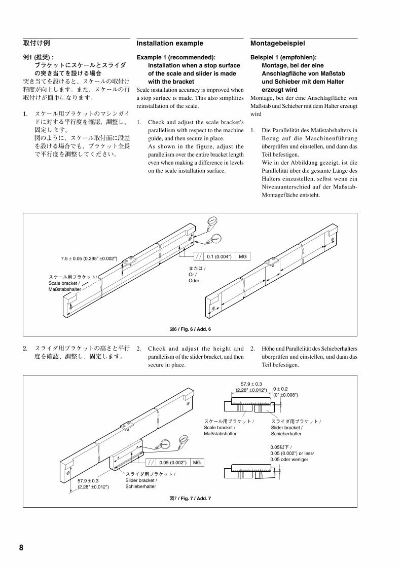
取付け例
例1 (推奨) :ブラケットにスケールとスライダの突き当てを設ける場合
突き当てを設けると、スケールの取付け精度が向上します。また、スケールの再取付けが簡単になります。
1. スケール用ブラケットのマシンガイドに対する平行度を確認、調整し、固定します。図のように、スケール取付面に段差を設ける場合でも、ブラケット全長で平行度を調整してください。
2. スライダ用ブラケットの高さと平行度を確認、調整し、固定します。
図6 / Fig. 6 / Add. 6
図7 / Fig. 7 / Add. 7
Installation example
Example 1 (recommended):Installation when a stop surfaceof the scale and slider is madewith the bracket
Scale installation accuracy is improved whena stop surface is made. This also simplifiesreinstallation of the scale.
1. Check and adjust the scale bracket'sparallelism with respect to the machineguide, and then secure in place.As shown in the figure, adjust theparallelism over the entire bracket lengtheven when making a difference in levelson the scale installation surface.
2. Check and adjust the height andparallelism of the slider bracket, and thensecure in place.
Montagebeispiel
Beispiel 1 (empfohlen):Montage, bei der eineAnschlagfläche von Maßstabund Schieber mit dem Haltererzeugt wird
Montage, bei der eine Anschlagfläche vonMaßstab und Schieber mit dem Halter erzeugtwird
1. Die Parallelität des Maßstabshalters inBezug auf die Maschinenführungüberprüfen und einstellen, und dann dasTeil befestigen.Wie in der Abbildung gezeigt, ist dieParallelität über die gesamte Länge desHalters einzustellen, selbst wenn einNiveauunterschied auf der Maßstab-Montagefläche entsteht.
2. Höhe und Parallelität des Schieberhaltersüberprüfen und einstellen, und dann dasTeil befestigen.

9
0.1 (0.004") MG
0.05 (0.002") MG
0 ± 0.2(0" ±0.008")
0.05以下 /�0.05 (0.002") or less/�0.05 oder weniger
スライダ用ブラケット /�Slider bracket /�Schieberhalter
スライダ用ブラケット /�Slider bracket /�Schieberhalter
スケール用ブラケット /�Scale bracket /�Maßstabshalter
図8 / Fig. 8 / Add. 8
3. スケールを各突き当て面に突き当てて、取付けます。
例2 :ブラケットにスケールとスライダの突き当てを設けない場合
1. スケール用ブラケットとスライダ用ブラケットのマシンガイドに対する平行度を調整し、固定します。スライダ用ブラケットのスケール用ブラケットに対する高さと平行度を調整し、固定します。
3. Bring the scale into contact with the stopsurfaces and install.
Example 2:Installation when a stop surfaceof the scale and slider is notmade with the bracket
1. Adjust the parallelism of the scalebracket and slider bracket with respectto the machine guide, and then secure inplace. Adjust the height and parallelismof the slider bracket with respect to thescale bracket, and then secure in place.
3. Bringen Sie den Maßstab zur Montagemit den Anschlagflächen in Berührung.
Beispiel 2:Montage, bei der keineAnschlagfläche von Maßstabund Schieber mit dem Haltererzeugt wird
1. Die Parallelität von Maßstabshalter undSchieberhalter in Bezug auf dieMaschinenführung einstellen, und danndie Tei le befest igen. Höhe undParallelität des Schieberhalters in Bezugauf den Maßstabshalter einstellen, unddann das Teil befestigen.
図9 / Fig. 9 / Add. 9

10
スケール両端から同じ距離 /�Same distance from scale ends /Gleicher Abstand von den Maßstabsenden
0.1 MG
t = 1.0スペーサ /�t = 1.0 spacer /�Abstandsstück t=1,0
図11 / Fig. 11 / Add. 11
2. スケール背面をダイヤルゲージで測定*しながら、スケール背面のマシンガイドに対する平行度を調整し、固定ねじを締めつけます。
*<測定方法>左右スケール両端から同じ距離の場所で、できるだけ測定間隔を広く取った2点で測定してください。中間フット付きのスケールの場合は、さらに中間フット部も測定してください。
3. スケールとスライダの隙間に、付属品のt=1.0スペーサを挿入し、スライダをスケールに突き当てながら、スライダの位置調整を行ないます。
■ 空気導入についてエンドキャップ部には、標準で空気導入用のM5タップ穴があります。詳細資料は別売の取扱説明書を参照してください。
2. Adjust the parallelism with respect to themachine guide of the scale rear whilemeasuring* the scale rear with a dialgauge. Tighten the set screws.
*<Measurement method>Measure a t two po in t s where themeasurement distance is as wide as possibleand at the same distance from the right andleft scale ends. If using a scale withintermediate foot plate, be sure to alsomeasure the intermediate foot plate.
3. Insert the supplied t=1.0 spacer inthe space between the scale andslider, and then adjust the sliderposition while bringing the sliderinto contact with the scale.
■■■■■ Air injectionIn the standard configuration, the end capsection is provided with a M5 tap hole for airinjection. For more detailed information,please refer to the Instruction Manual (soldseparately).
2. Stellen Sie die Parallelität in Bezug aufd i e M a s c h i n e n f ü h r u n g d e rMaßstabsrückseite ein, während Sie dieMaßstabsrückseite mit einer Messuhrm e s s e n * . Z i e h e n S i e d i eBefestigungsschrauben an.
*<Messmethode>Messen Sie an zwei Punkten, die möglichstweit voneinander entfernt sind und dengleichen Abstand vom rechten und linkenEnde des Maßstabs haben. Wenn Sie einenMaßstab mit Zwischenfußplatte verwenden,messen Sie auch die Zwischenfußplatte.
3. F ü h r e n S i e d a s m i t g e l i e f e r t eAbstandsstück t=1,0 in den Spaltzwischen Maßstab und Schieber ein, undstellen Sie dann die Schieberposition ein,während Sie den Schieber mit demMaßstab in Berührung bringen.
■■■■■ LufteinblasungBei der Standard-Konfiguration ist derEnddeckelteil mit einer M5-Gewindebohrungfür Lufteinblasung versehen. AusführlichereInformationen entnehmen Sie bitte derBedienungsanleitung (getrennt erhältlich).
図10 / Fig. 10 / Add. 10
11
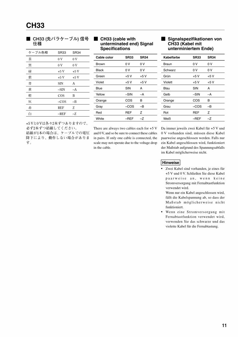
■ CH33 (先バラケーブル) 信号仕様
ケーブル色相 SR33 SR34
茶 0 V 0 V
黒 0 V 0 V
緑 +5 V +5 V
紫 +5 V +5 V
青 SIN A
黄 –SIN –A
橙 COS B
灰 –COS –B
赤 REF Z
白 –REF –Z
+5 Vと0 Vは各々2本ずつありますので、必ず2本ずつ結線してください。結線が1本の場合は、ケーブルでの電圧降下により、動作しない場合があります。
■■■■■ CH33 (cable withunterminated end) SignalSpecifications
Cable color SR33 SR34
Brown 0 V 0 V
Black 0 V 0 V
Green +5 V +5 V
Violet +5 V +5 V
Blue SIN A
Yellow –SIN –A
Orange COS B
Gray –COS –B
Red REF Z
White –REF –Z
There are always two cables each for +5 Vand 0 V, and so be sure to connect these cablesin pairs. If only one cable is connected, thescale may not operate due to the voltage dropin the cable.
■■■■■ Signalspezifikationen vonCH33 (Kabel mitunterminiertem Ende)
Kabelfarbe SR33 SR34
Braun 0 V 0 V
Schwarz 0 V 0 V
Grün +5 V +5 V
Violett +5 V +5 V
Blau SIN A
Gelb –SIN –A
Orange COS B
Grau –COS –B
Rot REF Z
Weiß –REF –Z
Da immer jeweils zwei Kabel für +5 V und0 V vorhanden sind, müssen diese Kabelpaarweise angeschlossen werden. Falls nurein Kabel angeschlossen wird, funktioniertder Maßstab aufgrund des Spannungsabfallsim Kabel möglicherweise nicht.
Hinweise• Zwei Kabel sind vorhanden, je eines für
+5 V und 0 V. Schließen Sie diese Kabelp a a r w e i s e a n , w e n n k e i n eStromversorgung mit Fernabtastfunktionverwendet wird.Wenn nur ein Kabel angeschlossen wird,fällt die Kabelspannung ab, so dass derM a ß s t a b m ö g l i c h e r w e i s e n i c h tfunktioniert.
• Wenn eine Stromversorgung mitFernabtastfunktion verwendet wird,verwenden Sie das schwarze und dasviolette Kabel für die Fernabtastung.
CH33

12
■ CN33 (インターポレ-タ) の取付け
注意
他の機器からのノイズ防止のため、以下の点にご注意ください。• 本機に結合して使用されるリレーやソレノイド、モータなどには、ノイズ防止の対策を講じてください。
• 電源ラインに他の機器からのノイズが混入する恐れのある場合、それらにノイズ防止対策を講じてください。
• 本機はアース線または、ねじ止めによる固定などで、機械本体と共に必ず接地を取るようにしてください。
• 出力ケーブルのシールド編組線は、出力コネクタ (付属) のケースに接続してください。また、インターポレータと受信装置取付部 (FG) が同電位になるよう接続してください。
取付け場所
注意
インターポレータは、周辺温度範囲0~50 ℃以内で、直射日光や熱源を避け、風通しのよい場所を選んで取付けてください。インターポレータ本体に水滴などがかかるような場所に設置する場合は、必ずカバーをかけるなどの防水処理を行なってください。
取付け手順
1. 外形寸法図に従い、取付穴の位置にM4タップ穴を加工します。(5ページ参照)
2. インターポレータのケースと面接触で確実な電気的導通を得るために、タップ穴の周囲の塗装を剥離します。
3. 2箇所に付属のねじ (M4 × 10 締付けトルク2 N · m) を取付け、固定します。
4. 出力コネクタをしっかりと差し込みます。
注意
• 取付け後は、ケーブルやコネクタに不要な力が加わらないように注意してください。故障の原因となります。
• スケールケーブルと出力ケーブルは、動力線とは100 mm以上離して配線してください。接近を避けられない場合、動力線と並行に配線せず、直交させてください。
■■■■■ Installing the CN33(Interpolator)
Notes
Take careful note of the following points toprevent noise from other equipment.• Implement noise prevention measures for
relays, solenoids, motors, and otherdevices connected and used with theinterpolator.
• Implement further noise preventionmeasures if there is a possibility of noisefrom other equipment mixing into thepower supply line.
• Be sure to ground the interpolator togetherwith the machine unit by securing with agrounding wire or screw holder.
• Connect the shielded braided wire of theoutput cable to the supplied case of outputconnector. Also, connect so that theinterpolator and receiver installation unit(FG) have the same electric potential.
Installation location
Notes
Install the interpolator in a well-ventilatedlocation with an ambient temperature of 0 ºCto 50 ºC and not exposed to direct sunlight orheat sources. If the interpolator is installed ina location where it is exposed to water drops,be sure to always attach a cover or otherwaterproof protection.
Installation
1. Drill M4 tap holes in the mounting holepositions according to the dimensionaldiagrams. (See page 5)
2. Remove the coating around the tap holeto obtain a full electrical conductor bysurface contact with the interpolatorcase.
3. Insert the supplied screws (M4 × 10,tightening torque of 2 N · m) into thetwo installation holes, and secure themin place.
4. Firmly insert the output connector.
Notes
• After installation, be careful that you donot apply unnecessary force to the cableor connector. This could damage theseparts.
• Arrange the scale cable and output cableso that they are at least 100 mm from thepower cable. If these cables must bearranged closer, place the cables so thatthey are perpendicular, not parallel, to thepower cable.
■■■■■ Installieren des CN33(Interpolator)
HinweiseBeachten Sie die folgenden Punkte sorgfältig,um Störbeeinflussung durch andere Geräte zuverhüten.• Ergreifen Sie Entstörungsmaßnahmen für
Relais, Magnetspulen, Motoren und anderemit dem Interpolator verbundenen undverwendeten Geräte.
• E r g r e i f e n S i e z u s ä t z l i c h eEntstörungsmaßnahmen, falls dieM ö g l i c h k e i t b e s t e h t , d a s s d i eStromversorgungsleitung Störeinstreuungvon anderen Geräten ausgesetzt wird.
• Erden Sie den Interpolator zusammen mitder Maschineneinheit durch Sicherung miteinem Erdungsdraht oder Schraubenhalter.
• Verbinden Sie den Geflechtschirm desAusgangskabels mit dem mitgeliefertenGehäuse des Ausgangsanschlusses.Nehmen Sie den Anschluss außerdem sovor, dass der Interpolator und dieEmpfänger-Installationseinheit (FG) dasgleiche elektrische Potential haben.
Installationsort
HinweiseInstallieren Sie den Interpolator an einem gutbelüfteten Ort mit einer Umgebungstemperaturvon 0 ºC bis 50 ºC, der weder direktemS o n n e n l i c h t n o c h i rg e n d w e l c h e nWärmequellen ausgesetzt ist. Muss derInterpolator an einem Ort installiert werden,wo er Wassertropfen ausgesetzt ist, bringen Sieunbedingt eine Abdeckung oder einengeeigneten Spritzwasserschutz an.
Installation
1. M4-Gewindebohrungen gemäß denMaßzeichnungen an den Positionen derMontagelöcher bohren. (siehe Seite 5)
2. D i e B e s c h i c h t u n g u m d i eGewindebohrung entfernen, um einenvollwertigen elektrischen Leiter durchO b e r f l ä c h e n k o n t a k t m i t d e mInterpolatorgehäuse zu erhalten.
3. Die mitgelieferten Schrauben (M4 × 10,Anzugsmoment 2 N · m) in dieMontagelöcher einführen und sichern.
4. Den Ausgangsanschluss fest einschieben.
Hinweise• Achten Sie nach der Installation darauf, dass
das Kabel oder der Anschluss keinerunnötigen Krafteinwirkung ausgesetzt wird.Anderenfalls könnten diese Teile beschädigtwerden.
• Verlegen Sie Maßstabskabel undAusgangskabel so, dass sie mindestens 100mm Abstand vom Stromkabel haben.Müssen diese Kabel enger zusammenverlegt werden, ordnen Sie sie senkrecht,nicht parallel, zum Stromkabel an.
CN33
13
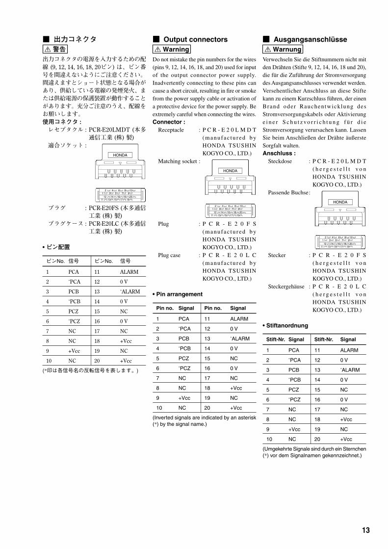
■ 出力コネクタ 警告
出力コネクタの電源を入力するための配線 (9, 12, 14, 16, 18, 20ピン) は、ピン番号を間違えないようにご注意ください。間違えますとショート状態となる場合があり、供給している電線の発煙発火、または供給電源の保護装置が動作することがあります。充分ご注意のうえ、配線をお願いします。使用コネクタ :レセプタクル : PCR-E20LMDT (本多
通信工業 (株) 製)適合ソケット :
プラグ : PCR-E20FS (本多通信工業 (株) 製)
プラグケース : PCR-E20LC (本多通信工業 (株) 製)
• ピン配置
ピンNo. 信号 ピンNo. 信号
1 PCA 11 ALARM
2 *PCA 12 0 V
3 PCB 13 *ALARM
4 *PCB 14 0 V
5 PCZ 15 NC
6 *PCZ 16 0 V
7 NC 17 NC
8 NC 18 +Vcc
9 +Vcc 19 NC
10 NC 20 +Vcc
(*印は各信号名の反転信号を表します。)
■■■■■ Output connectors Warning
Do not mistake the pin numbers for the wires(pins 9, 12, 14, 16, 18, and 20) used for inputof the output connector power supply.Inadvertently connecting to these pins cancause a short circuit, resulting in fire or smokefrom the power supply cable or activation ofa protective device for the power supply. Beextremely careful when connecting the wires.Connector :
Receptacle : P C R - E 2 0 L M D T(manufac tu red b yHONDA TSUSHINKOGYO CO., LTD.)
Matching socket :
Plug : P C R - E 2 0 F S(manufac tu red b yHONDA TSUSHINKOGYO CO., LTD.)
Plug case : P C R - E 2 0 L C(manufac tu red b yHONDA TSUSHINKOGYO CO., LTD.)
• Pin arrangement
Pin no. Signal Pin no. Signal
1 PCA 11 ALARM
2 *PCA 12 0 V
3 PCB 13 *ALARM
4 *PCB 14 0 V
5 PCZ 15 NC
6 *PCZ 16 0 V
7 NC 17 NC
8 NC 18 +Vcc
9 +Vcc 19 NC
10 NC 20 +Vcc
(Inverted signals are indicated by an asterisk(*) by the signal name.)
■■■■■ Ausgangsanschlüsse Warnung
Verwechseln Sie die Stiftnummern nicht mitden Drähten (Stifte 9, 12, 14, 16, 18 und 20),die für die Zuführung der Stromversorgungdes Ausgangsanschlusses verwendet werden.Versehentlicher Anschluss an diese Stiftekann zu einem Kurzschluss führen, der einenBrand oder Rauchentwicklung desStromversorgungskabels oder Aktivierunge i n e r S c h u t z vo r r i c h t u n g f ü r d i eStromversorgung verursachen kann. LassenSie beim Anschließen der Drähte äußersteSorgfalt walten.Anschluss :
Steckdose : P C R - E 2 0 L M D T( h e r g e s t e l l t v o nHONDA TSUSHINKOGYO CO., LTD.)
Passende Buchse:
Stecker : P C R - E 2 0 F S( h e r g e s t e l l t v o nHONDA TSUSHINKOGYO CO., LTD.)
Steckergehäuse : P C R - E 2 0 L C( h e r g e s t e l l t v o nHONDA TSUSHINKOGYO CO., LTD.)
• Stiftanordnung
Stift-Nr. Signal Stift-Nr. Signal
1 PCA 11 ALARM
2 *PCA 12 0 V
3 PCB 13 *ALARM
4 *PCB 14 0 V
5 PCZ 15 NC
6 *PCZ 16 0 V
7 NC 17 NC
8 NC 18 +Vcc
9 +Vcc 19 NC
10 NC 20 +Vcc
(Umgekehrte Signale sind durch ein Sternchen(*) vor dem Signalnamen gekennzeichnet.)
HONDA
2 4 6 8 101 3 5 7 9
12 14 16 18 2011 13 15 17 19
HONDA
2 4 6 8 101 3 5 7 9
12 14 16 18 2011 13 15 17 19
HONDA
2 4 6 8 101 3 5 7 9
12 14 16 18 2011 13 15 17 19

14
■ スイッチの設定インターポレータには、本体側面から操作できるMODEスイッチがあります。
• MODEスイッチ
■■■■■ Switch settingsThe interpolator has MODE switches that canbe operated from the scale side.
• MODE switches
■■■■■ SchaltereinstellungenDer Interpolator besitzt MODE-Schalter, dievon der Maßstabseite aus betätigt werdenkönnen.• MODE-Schalter
No. / スイッチの名称 / 出荷時設定 / 設定内容 /Nr. Switch name / Default setting / Setting description /
Schaltername Standardeinstellung Einstellungsbeschreibung
1 ディレクション/ ON ON : A相信号進み OFF : B相信号進みDirection / ON : A signal is ahead OFF : B signal is aheadRichtung ON : A-Signal eilt vor OFF : B-Signal eilt vor
2 分解能1 / ONResolution 1 /Auflösung 1
3 分解能2 / ONResolution 2 /Auflösung 2
4 原点信号幅 / ON ON : A相信号、B相信号共にHigh OFF : A相信号1周期の間、同期Reference point signal width / レベルの間、同期原点出力 / 原点出力 /Bezugspunktsignalbreite ON : A synchronized reference OFF: A synchronized reference
point is output when both the A point is output during the Asignal and B signal are at the signal cycle /high level / OFF: Ein synchronisierterON : Ein synchronisierter Bezugspunkt wird während desBezugspunkt wird ausgegeben, A-Signal-Zyklus ausgegebenwährend A- und B-Signalhochpegelig sind
5 アラーム・モード / OFF ON : 自動解除モード / OFF : 保持モード /Alarm mode / ON : Automatic reset mode / OFF : Hold mode /Alarmmodus ON : Modus für automatische OFF : Haltemodus
Rücksetzung
6 最小位相差時間1 / ONMinimum phase difference time 1 /Minimale Phasendifferenzzeit 1
7 最小位相差時間2 / ONMinimum phase difference time 2 /Minimale Phasendifferenzzeit 2
8 1分解能ヒステリシス / OFFResolution hysteresis /Auflösungshysterese
9 ヒステリシス1 / ONHysteresis 1 /Hysterese 1
10 ヒステリシス2 / OFFHysteresis 2 /Hysterese 2
詳細は別売の取扱説明書をご参照ください。For details, refer to the Instruction Manual (sold separately).Einzelheiten entnehmen Sie bitte der Bedienungsanleitung (getrennt erhältlich).
SW2 SW3 分割数 (分解能) / Number of divisions (Resolution) /Anzahl der Teilungen (Auflösung)
ON ON 800 (0.05 µm) / 800 (0,05 µm)
OFF ON 400 (0.1 µm) / 400 (0,1 µm)
ON OFF 80 (0.5 µm) / 80 (0,5 µm)
OFF OFF 40 (1.0 µm) / 40 (1,0 µm)
SW6 SW7
ON ON 62.5 ns / 62,5 ns
OFF ON 125 ns
ON OFF 187.5 ns / 187,5 ns
OFF OFF 250 ns
SW8 SW9 SW10 ヒステリシス量 / Hysteresis / Hysterese
ON 無効 / 無効 / 設定された分解能 ※SW2、SW3参照 /Disabled / Disabled / User-selected resolution *SW2, SW3 /Deaktiviert Deaktiviert Benutzerdefinierte Auflösung *SW2, SW3
OFF ON ON 0.005 µm / 0,005 µm
OFF OFF ON 0.01 µm / 0,01 µm
OFF ON OFF 0.02 µm / 0,02 µm
OFF OFF OFF 0.04 µm / 0,04 µm

SR33/SR34, CH33, CN33

このマニュアルに記載されている事柄の著作権は当社にあり、説明内容は機器購入者の使用を目的としています。したがって、当社の許可なしに無断で複写したり、説明内容(操作、保守など)と異なる目的で本マニュアルを使用することを禁止します。
The material contained in this manual consists ofinformation that is the property of Magnescale Co., Ltd.and is intended solely for use by the purchasers of theequipment described in this manual.Magnescale Co., Ltd. expressly prohibits theduplication of any portion of this manual or the usethereof for any purpose other than the operation ormaintenance of the equipment described in thismanual without the express written permission ofMagnescale Co., Ltd.
Le matériel contenu dans ce manuel consiste eninformations qui sont la propriété de MagnescaleCo., Ltd. et sont destinées exclusivement à l'usagedes acquéreurs de l'équipement décrit dans cemanuel.Magnescale Co., Ltd. interdit formellement la copie dequelque partie que ce soit de ce manuel ou son emploipour tout autre but que des opérations ou entretiensde l'équipement à moins d'une permission écrite deMagnescale Co., Ltd.
Die in dieser Anleitung enthaltenen Informationensind Eigentum von Magnescale Co., Ltd. und sindausschließlich für den Gebrauch durch den Käufer derin dieser Anleitung beschriebenen Ausrüstungbestimmt.Magnescale Co., Ltd. untersagt ausdrücklich dieVervielfältigung jeglicher Teile dieser Anleitung oderden Gebrauch derselben für irgendeinen anderenZweck als die Bedienung oder Wartung der in dieserAnle i tung beschr iebenen Ausrüstung ohneausdrückliche schriftliche Erlaubnis von MagnescaleCo., Ltd.

SR33 / SR34,CH33, CN33
お客様にお届けする日時が当社工場において記録される場合 (納入日が工場で特定できる場合)、保証書への記入は省略されます。
フリガナ�
電話 - - 印�
お買上げ店住所・店名�
〒 電話 - -
お買上げ日 年 月 日�
本 体 1 年 �
型 名�
期 間�
保 証�
�
お 客 様�
お
名
前�
ご
住
所�
様�
保 証 書保証規定
z 保証の範囲q 取扱説明書、本体添付ラベル等の注意書に従った正
常な使用状態で、保証期間内に故障した場合は、無償修理いたします。
w 本書に基づく保証は、本商品の修理に限定するものとし、それ以外についての保証はいたしかねます。
x 保証期間内でも、次の場合は有償修理となります。q 火災、地震、水害、落雷およびその他天災地変によ
る故障。w 使用上の誤りおよび不当な修理や改造による故障。e 消耗品および付属品の交換。r 本書の提示が無い場合。t 本書にお買い上げ日、お客様名、販売店名等の記入
が無い場合。(ただし、納品書や工事完了報告書がある場合には、その限りではありません。)
c 離島、遠隔地への出張修理および持込修理品の出張修理については、出張に要する実費を別途申し受けます。
v 本書は日本国内においてのみ有効です。
b 本書の再発行はいたしませんので、紛失しないよう大切に保管してください。
本書はお買上げ日から保証期間中に故障が発生した場合には、右記保証規定内容により無償修理を行うことをお約束するものです。

2010.4Printed in Japan
©2003 Magnescale Co., Ltd.
SR33 / SR34, CH33, CN332-919-618-05このマニュアルは再生紙を使用しています。
〒 108-6018 東京都港区港南2丁目 15番1号 品川インターシティA棟18階
Shinagawa Intercity Tower A-18F, 2-15-1, Konan, Minato-ku, Tokyo 108-6018, Japan