sq 585 mainboard - bcm advanced researchsq 585 1 introduction how to use this manual this manual...
TRANSCRIPT

SQ 585 1
SQ 585 MainboardUser‘s Manual

SQ 5852
User NoticeStatic Electricity Precaution
Static electricity can easily damage your SQ585 mainboard. Byobserving a few basic precautions can help safeguard against damagethat could result in expensive repairs. Follow the simple measuresbelow to protect your equipment from static electricity damage:
1. Keep the mainboard and other system components in their anti-static packaging until you are ready to install them.
2. Touch a grounded surface before you remove any systemcomponent from its protective anti-static packaging. Unpackingand installation should be done on a grounded, anti-static mat. Theoperator should be wearing an anti-static wristband, grounded atthe same points as the anti-static mat.
3. After removing the mainboard from its original packaging, onlyplace it on a grounded, anti-static surface component side up.Immediately inspect the board for damage. Due to shifting duringshipping, it is suggested that the installer press down on all of thesocket ICs to ensure they are properly seated. Do this only withthe board placed on a firm flat surface.
4. During configuration and installation touch a grounded surfacefrequently to discharge any static electrical charge that may havebuilt up in your body. The best precaution is to wear a groundedwrist strap. When handling the mainboard or an adapter card avoidtouching its components. Handle the mainboard and adapter cardseither by the edges or by the adapter card case mounting bracket.

SQ 585 3
The information presented in this publication has been carefullyscreened for reliability.The manufacturer provides this manual “As is” with no warranties ofany kind, either express or implied, including, but not limited to, theimplied warranties or conditions of this product fitness for anyparticular purpose. In no event shall manufacturer be liable for any lossof profits, loss of business, loss of data, interruption of business, orindirect, special, incidental, or consequential damages of any kind, evenif manufacturer has been advised of the possibility of such damagesarising from any defect or error in this manual or product. Themanufacturer has the right to change this specification without pre-notice.
Trademarks and product names appearing in this manual are may ormay not be registered of their respective holders.

SQ 5854
Table of Contents1 INTRODUCTION................................ ................................ .......................... 1-1
1.1 HOW TO USE THIS MANUAL......................................................................... 1-11.2 ITEM CHECKLIST........................................................................................1-1
2 KEY FEATURES................................ ................................ .......................... 2-1
2.1 MAINBOARD LAYOUT................................................................................. 2-2
3 INSTALLATION................................ ................................ ........................... 3-1
3.1 INSTALLATION PREVIEW............................................................................. 3-13.2 JUMPERS: ................................................................................................... 3-13.3 EXPANSION SLOTS:.....................................................................................3-13.4 CONNECTORS.............................................................................................3-23.5 INSTALLATION STEPS ................................................................................. 3-2
4 BIOS SETUP................................ ................................ ................................ .. 4-1
4.1 ENTERING SETUP .......................................................................................4-14.2 CONTROL KEYS .........................................................................................4-14.3 THE MAIN MENU .......................................................................................4-24.4 STANDARD CMOS SETUP MENU ................................................................4-44.5 BIOS FEATURES SETUP MENU.................................................................... 4-74.6 CHIPSET FEATURES SETUP MENU.............................................................. 4-114.7 POWER MANAGEMENT SETUP MENU......................................................... 4-124.8 PCI CONFIGURATION SETUP MENU........................................................... 4-144.9 INTEGRATED PERIPHERALS MENU ............................................................. 4-154.10 PASSWORD SETTING ............................................................................... 4-174.11 IDE HDD AUTO DETECTION.................................................................. 4-18
5 VGA INSTALLATION................................ ................................ ................. 5-1
5.1 INTRODUCTION..........................................................................................5-15.2 SOFTWARE DRIVERS...................................................................................5-3

SQ 585 1
Introduction
How to use this ManualThis manual provides information necessary for Original Equipment Manufactures(OEMs) to build a PC-AT compatible system using the Pentium PCI mainboard. For theend-users, this manual is a good reference to understand and properly use the mainboard.This manual is organized into 4 chapters. Its purpose is to explain the installationprocedures and operations of the SQ 585 All-In-One mainboard as specified below.
Introduction : Manual information and checklist
Key Features : An overview of the specifications of this mainboard
Installation : Instructions on how to setup the mainboard
BIOS setup : BIOS software setup information
Item ChecklistThe package should contain followings tick “ ” item, if you discover any missing items,or any damage . Please contact your retailer Immediately.
The SQ585 mainboard
This SQ585 user‘s manual
2 serial port ribbon cables attached to a mounting bracket
1 parallel ribbon cable attached to a mounting bracket
1 VGA ribbon cable attached to a mounting bracket
1 IDE ribbon cable
1 Floppy ribbon cable
1 CDROM (VGA Driver)
PS/2 mouse cable with mounting bracket (optional )
USB (2-port) cable with mounting bracket(optional)
SQ 5851
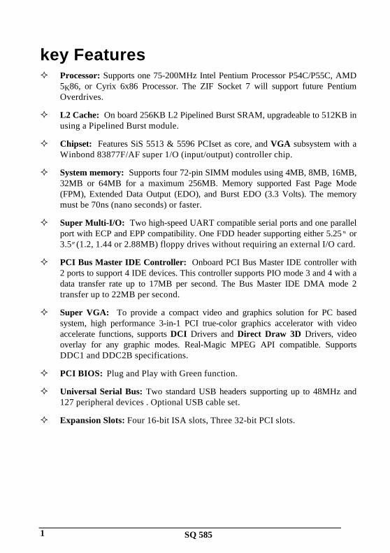
key FeaturesProcessor: Supports one 75-200MHz Intel Pentium Processor P54C/P55C, AMD5K86, or Cyrix 6x86 Processor. The ZIF Socket 7 will support future PentiumOverdrives.
L2 Cache: On board 256KB L2 Pipelined Burst SRAM, upgradeable to 512KB inusing a Pipelined Burst module.
Chipset: Features SiS 5513 & 5596 PCIset as core, and VGA subsystem with aWinbond 83877F/AF super 1/O (input/output) controller chip.
System memory: Supports four 72-pin SIMM modules using 4MB, 8MB, 16MB,32MB or 64MB for a maximum 256MB. Memory supported Fast Page Mode(FPM), Extended Data Output (EDO), and Burst EDO (3.3 Volts). The memorymust be 70ns (nano seconds) or faster.
Super Multi-I/O: Two high-speed UART compatible serial ports and one parallelport with ECP and EPP compatibility. One FDD header supporting either 5.25“ or3.5”(1.2, 1.44 or 2.88MB) floppy drives without requiring an external I/O card.
PCI Bus Master IDE Controller: Onboard PCI Bus Master IDE controller with2 ports to support 4 IDE devices. This controller supports PIO mode 3 and 4 with adata transfer rate up to 17MB per second. The Bus Master IDE DMA mode 2transfer up to 22MB per second.
Super VGA: To provide a compact video and graphics solution for PC basedsystem, high performance 3-in-1 PCI true-color graphics accelerator with videoaccelerate functions, supports DCI Drivers and Direct Draw 3D Drivers, videooverlay for any graphic modes. Real-Magic MPEG API compatible. SupportsDDC1 and DDC2B specifications.
PCI BIOS: Plug and Play with Green function.
Universal Serial Bus: Two standard USB headers supporting up to 48MHz and127 peripheral devices . Optional USB cable set.
Expansion Slots: Four 16-bit ISA slots, Three 32-bit PCI slots.
SQ 585 2
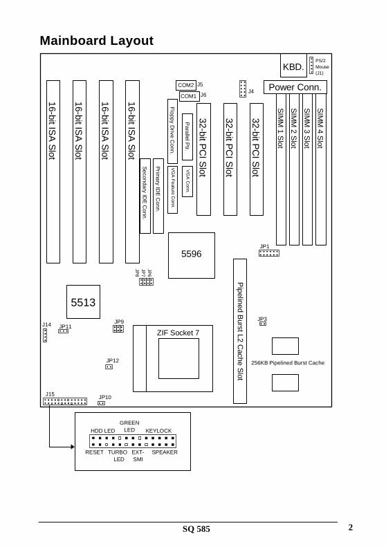
Mainboard Layout
16-bit ISA
Slot
16-bit ISA
Slot
16-bit ISA
Slot
16-bit ISA
Slot
32-bit PC
I Slot
32-bit PC
I Slot
32-bit PC
I Slot
SIM
M 1 S
lot
SIM
M 2 S
lot
SIM
M 3 S
lot
SIM
M 4 S
lot
Pipelined B
urst L2 Cache S
lot
KBD.
Secondary ID
E C
onn.
Prim
ary IDE
Conn.
Floppy Drive C
onn.V
GA
Feature Conn.
VG
A C
onn.P
arallel Ptr.
COM2
COM1
5596
5513
Power Conn.
PS/2Mouse(J1)
JP1
J15
SPEAKEREXT-SMI
TURBO LED
RESET
HDD LED KEYLOCKGREEN
LED
JP10
J14 JP11JP9
JP12
JP3
J4J6
J5
JP6
JP7
JP8
256KB Pipelined Burst Cache
ZIF Socket 7

SQ 5851
Installation
Installation PreviewBefore you install the SQ585 All-In-One mainboard into the system chassis, you mayfind it convenient to first configure the mainboard hardware. This section describes howto configure the jumper settings, install memory modules and how to attach the varioussystem components. Before using your computer you must review the following 6 steps:
Jumpers settings.
Installation of DRAM memory modules.
Installation of the CPU.
Installation of IDE, I/O, VGA cables and the power supply connection.
Installation of expansion cards.
Setup of the system BIOS software.
Jumpers:JP10 CPU 3V Voltage regulator output selection.
JP12 CPU 2V Voltage regulator output selection.
JP3 Intel P54C/P55C, AMD 5K86, or Cyrix 6x86/M2 CPUselection.
JP11 CMOS RAM (Operation/Clear CMOS data).
JP7; JP8 CPU external clock (Bus) frequency selection.
JP5 CPU (Bus) frequency ratio.
JP6 CPU (Bus) frequency ratio.
Expansion Slots:SIMM Sockets DRAM SIMM module sockets.
ZIF Socket 7 Socket for Central Processing Unit (CPU).
ISA Slots 16-bit ISA Bus expansion slots.
PCI Slots 32-bit PCI Bus expansion slots.

SQ 585 2
ConnectorsKeyboard (J5) Keyboard connector (5-pin).
PS/2 Mouse (J1) PS/2 Mouse Header (5-pin).
Parallel Port (J7) Parallel port connector (26-pin Block).
Serial Port (J5, J6) Serial ports COM1 & COM2 (10-pin Block).
Floppy Drive (J9) Floppy drive connector (34-pin Block).
Power Input (J3) Power connector (12-pin Block).
Primary IDE (J11) Primary IDE connector (40-pin Block).
Secondary IDE (J12) Secondary IDE connector (40-pin Block).
VGA (J8) VGA connector (16-pin).
Feature connector (J10)VGA Feature Connector (34-pin).
Key Lock (J15) Keyboard lock switch connector (5-pins).
Speaker (J15) Speaker connector (4-pin).
Green LED (J15) Suspend LED connector (2-pin).
SMI switch (J15) Suspend switch connector (2-pin).
HDD LED (J15) Hard Disk drive LED connector (4-pin).
Turbo LED (J15) Turbo LED(2-pin) .
Reset Switch (J15) Reset switch connector (2-pin).
WARNING: Do not apply power if the mainboard appears damaged or items aremissing from the mainboard .
Installation Steps
Jumper SettingsYou can configure the hardware options by setting jumper on the mainboard. A jumper isa set of two or more metal pins in a plastic base attached to the mainboard. A plastic“Jumper cap” with a metal (conductive) plate inside fits over two pins to create anelectrical contact or short between them. This contact establishes a hardware setting andis referred to as a “closed” jumper setting. Some jumpers have two pins while othersmay have three or more. Jumpers are sometimes combined into sets called jumper blockswhere all the jumpers in the block must be set together to establish a hardware setting. In

SQ 5853
this manual the jumper settings will be described as graphically using a (s)trianglealways marking Pin 1. Those jumpers with two pins will be shown as closed and open.A jumper is referred to as closed by placing the plastic jumper cap over the two jumperpins and as open by removing the jumper cap. Some jumpers are oriented vertically andother horizontally with Pin 1 marked as (s=P1).
Jumpers, Jumper Caps, and Jumper Blocks
Jumper cap2-pin jumper3-pin jumper4-pin jumperJumper block
For Setting 3-pin jumpers
P 1 P 2 P 3
Jumper Pins 1 & 2 are closed with a jumper cap
P 1 P 2 P 3
Jumper Pins 2 & 3 are closed with a jumper cap
Setting 2-pin jumpers
This jumper is closed with the jumper cap is placed over the 2 pins
This jumper is open with the jumper cap removed from the 2 pins
WARNING: Some pins are used for connectors or power sources.These are clearly marked separately from the jumpers listed in“Mainboard Layout”. Any improper placing of jumper caps over theseconnectors will result in damage to your motherboard.CPU Voltage Selection Jumpers (JP9, JP10, & JP12)
Intel/AMD Selection JP9 JP10 JP12
SQ 585 4
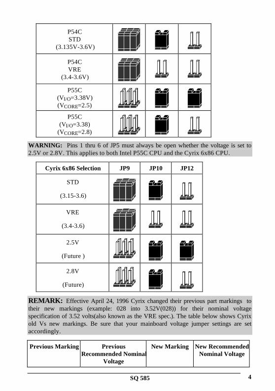
P54CSTD
(3.135V-3.6V)
P54CVRE
(3.4-3.6V)
P55C(VI/O=3.38V)(VCORE=2.5)
P55C(VI/O=3.38)
(VCORE=2.8)
WARNING: Pins 1 thru 6 of JP5 must always be open whether the voltage is set to2.5V or 2.8V. This applies to both Intel P55C CPU and the Cyrix 6x86 CPU.
Cyrix 6x86 Selection JP9 JP10 JP12
STD
(3.15-3.6)
VRE
(3.4-3.6)
2.5V
(Future )
2.8V
(Future)
REMARK: Effective April 24, 1996 Cyrix changed their previous part markings totheir new markings (example: 028 into 3.52V(028)) for their nominal voltagespecification of 3.52 volts(also known as the VRE spec.). The table below shows Cyrixold Vs new markings. Be sure that your mainboard voltage jumper settings are setaccordingly.
Previous Marking PreviousRecommended Nominal
Voltage
New Marking New RecommendedNominal Voltage

SQ 5855
Blank 3.3V 3.3V or 3.52V 3.52V
016 3.3V N/A N/A
028 3.52V 3.52V(028) 3.52V
CMOS Settings(Operation/Clear CMOS Data) (JP11)The JP11 allows you to clear the SQ585 mainboard CMOS memory and Real TimeClock (RTC) data. The CMOS memory maintains the system configuration informationand RTC provides the system with the date and time. Make sure this jumper is put on Pin1 and Pin 2 for normal operation.
Normal (Default) Clear CMOS
P 1 P 2 P 3 P 1 P 2 P 3
Clear CMOS procedure :To clear the stored CMOS data, do the following :
1) the system turned off, ⇒ 2) close JP11 ⇒ 3) Open JP11 ⇒ 4) ⇒ Power on ⇒ 5)Re-setup the BIOS (refer to enter the BIOS setup menu, hold down <DEL> during thesystem boot sequence).
NOTICE: Under some circumstances it is possible that the CMOS configurationsettings may be lost or corrupted causing the system to malfunction. This is not a seriousproblem. If this happens, run the BIOS setup utility and re-enter your configurationsettings. When you restart the computer, the system should work normally.
CPU Type and Selection (JP5, JP6, JP7, JP8)The system speed depends upon the frequency of CLOCK GENERATOR which isdetermined by jumpers. These jumpers tell the system what speed to run at. Currently,this mainboard speed range is from 75MHz to 200MHz. The CPU input frequency mustmatch the frequency of CLOCK GEN or it will cause the system to malfunction. Forexample, setting a 75MHz CPU to run at 90MHz will cause the system to malfunction.
Intel CPU Setting JP3 JP5 JP6 JP7 JP8
75MHz
90MHz

SQ 585 6
100MHz
120MHz
133MHz
150MHz
166MHz
180MHz
200MHz
Cyrix 6X86 Setting JP3 JP5 JP6 JP7 JP8
100MHz(=P120+)
110MHz(=P133+)
120MHz(=P150+)
133MHz(=P166+)
NOTICE: When installing the CPU into the CPU socket, be sure that PIN 1 of the CPUis in the same corner as the PIN 1 of socket. The CPU is an extremely sensitive electriccomponent and can be easily damaged by static electricity.

SQ 5857
Expansion SlotsThe SQ585 has 7 expansion Slots On-board, there are 3 16-bit ISA, and 4 32-bit PCIexpansion Slots.
SIMM Slots-System Memory (DRAM)You can configure the system memory size in a variety of ways by in using differentcombinations of the four 72-pin DRAM SIMM modules. The memory must be 70ns(nano seconds) or faster using either Fast Page Mode or Extended Data Output (EDO)types. The memory chart below shows the different memory size combinations available.Please pay attention to the following restrictions:
You must use one pair of sockets at a time in sequence (i.e. SIMM1 and SIMM2, orall four sockets at once). Each pair of modules must be the same size and speed
Memory Module Combinations
Total Memory (Slot 1-4) Bank 0 (Slot 1 & 2) Bank 1 (Slot 3 & 4)
8MB 4MBx2 None16MB 8MBx2 None32MB 16MBx2 None64MB 32MBx2 None8MB None 4MBx216MB None 8MBx232MB None 16MBx264MB None 32MBx216MB 4MBx2 4MBx224MB 4MBx2 8MBx240MB 4MBx2 16MBx272MB 4MBx2 32MBx224MB 8MBx2 4MBx232MB 8MBx2 8MBx248MB 8MBx2 16MBx280Mb 8MBx2 32MBx240MB 16MBx2 4MBx248MB 16MBx2 8MBx264MB 16MBx2 16MBx296MB 16MBx2 32MBx272MB 32MBx2 4MBx280MB 32MBx2 8MBx296MB 32MBx2 16MBx2128MB 32MBx2 32MBx2

SQ 585 8
Installation Procedure for System Memory
Insert the SIM
M M
odule intothe S
IMM
Socket at 45°
Pin 1
1. PIN1 of the SIMM module must match with the PIN1 of the SIMM socket.
2. The module will only insert into the socket one way. An orientation cut-out willprevent you from inserting it the wrong way.
3. Insert the DRAM module into the SIMM socket at a 45 degree angle. If Pin 1 of theSIMM does not line up with Pin 1 of the socket, the SIMM will not insert into thesocket. After inserting the SIMM module completely into socket, push the SIMMmodule into a vertical position.
4. The module should click into place with the retaining clips at each end of the socketsnapping behind the module to secure it.
5. To release the memory module push both retaining clips outwards and carefullyrock the module forward.
IMPORTANT: Do not use SIMM modules that use an extra TTL chip to convert thememory module from asymmetric to symmetric.
ZIF Socket 7 for Central Processing Unit(CPU)The SQ585 comes with a 321-pin ZIF Socket 7 for installing the CPU. The Socket 7 willalso support future Pentium up-grade processors. It is strongly recommended that aheatsink and CPU cooling fan be used to prevent the CPU from overheating. (Tip)Applying a thermal of jelly between the CPU and the heatsink/fan will further cool theCPU.
Blank CornerNotch

SQ 5859
Installation Procedure(CPU)To install a CPU, remember to take careful precaution against static electric discharge.The basic procedure is as follows:
IMPORTANT: you must set jumpers JP1, JP2, & JP5 (see page 3) to correct Busfrequency.
1. Turn off your system and disconnect the power source.
2. Remove the existing CPU from the ZIF socket by pulling the ZIF lever upwards ata 90 -degree angle.
3. Insert the CPU with the correct orientation as below shown. Use the notched cornerof the CPU as your guide. The notch in the corner of the CPU should correspondwith PIN1 of the ZIF socket (Notice: Pin 1 is the blank corner of the ZIF socketwith one pin hole missing).
4. Once the CPU is inserted close the socket‘s lever.
WARNING: Without a fan, the CPU can overheat and will cause damage to both theCPU and the SQ585 motherboard.
ISA & PCI SlotsThe SQ585 mainboard has four 16-bit ISA and three 32-bit PCI Slots.
16-bit ISA Slot
32-bit PCI Slot
Installation Procedure:To install expansion cards, please read the expansion card‘s documentation forinstructions.
NOTICE: Some expansion cards require an IRQ to work and may cause a conflict.There are a total of 16 IRQs but only 6 are free for expansion cards. In case of a conflictplease contact the system manufacturer for technical support.
1. There are two types of ISA expansion cards, design-Legacy and P-n-P (Plug &Play). For Legacy cards you must set the card‘s jumpers manually. For Plug andPlay cards, your system will arrange the IRQs automatically. You can verify the

SQ 585 10
IRQ allocation either by using Microsoft’s Diagnostic (MSD.EXE) utility which isin the Windows directory or through the Windows 95 resources menu.
2. An IRQ is automatically assigned to PCI expansion cards. All of the PCI slots onthe mainboard use an interrupt. Be sure that the jumpers on your PCI cards are setto interrupt A.
Connectors WARNING: When you connect the ribbon cable, you must ensure PIN 1 of the cablematches PIN 1 of the connector.
PS/2 Mouse header(J1)This SQ585 mainboard provides a default PS/2 mouse header that supports an optionalPS/2 mouse connector cable & bracket
PS2 Mouse headerPS2 Cable with Bracket
Pin1
Parallel Port (J7)This connector supports a parallel port ribbon cable and mounting bracket. Connect theribbon cable to this connector and mount the bracket to the back of the case.
Pin 1
Parallel port
Serial Ports (J5, J6)These connectors support two serial port ribbon cables (Com1& Com2). Connect theribbon cable to these connectors and mount the bracket to the back of the case.

SQ 58511
Serial Ports
Pin1Pin1
COM2 (J5) COM1 (J6)
Floppy Driver (J9)This connector supports the floppy drive via a floppy drive ribbon cable. The ribbon cablecan support one to two floppy drives.
Floppy Drive Connector
Pin 1
Primary IDE (J11)This connector supports two primary IDE devices via a ribbon cable. When two IDEdevices are installed using the primary IDE connector make sure that the second IDEdevice is adjusted to slave mode as instructed in the device‘s manual.
Primary IDE Connector
Pin 1
Secondary IDE (J12)This connector supports two secondary IDE devices via a ribbon cable. When two IDEdevices are installed using the secondary IDE connector make sure that the second IDEdevice is adjusted to slave mode as instructed in the device‘s manual.

SQ 585 12
Secondary IDE Connector
Pin 1
VGA (J8) & Feature Connector (J10)This SQ585 mainboard has Super VGA onboard. This connector supports the VGAoutput via a ribbon cable. Connect the VGA ribbon cable to this connectors and mountthe bracket to the back of the case
Feature Connector
VGA Header
Pin 1
Pin 1
Universal Serial Bus (USB) Header (J4)This SQ585 mainboard has two USB headers onboard. USB devices provide a moreconvenient operating environment and improve data transferring capacity. True Plug-and-Play, this new bus technology will support over 127 different peripherals through a Hub.
USB Header
USB1
Pin1
USB2
Key Lock (5-pin )This connector supports the case-mounted switch for locking the keyboard for securitypurposes.

SQ 58513
Keylock Connector
Speaker (4-pin)This connector supports the case-mounted speaker.
Speaker connector
GREEN LED (2-pin )This connector supports the case-mounted Green LED.
GREEN LED
EXT-SMI Switch (2-pin)This connector supports the case-mounted suspend switch allowing you to manuallyplace the system into a suspend mode or “Green” mode. During Green mode, the systemactivity will be decreased to save energy when the system is not in use. If you want to usethis feature, the “Suspend Switch” in the Power Management Setup of the BIOS shouldbe enabled.
EXT SMIConnector

SQ 585 14
HDD LED (4-pin)(J29)This connector supports the hard disk activity indicator light on the case.
HDD LED
Turbo LED (2-pin)This connector supports the turbo LED. It will always be is on because the mainboard‘sturbo function is always on.
Turbo LED
Reset Switch (2-pin)This connector supports the case-mounted reset. It is advised that the reset switch beused for rebooting the system in order to extend the life of the system‘s power supply.
Reset SwitchConnector
Keyboard (J2)This connector supports a standard 101 enhanced IBM-compatible keyboard.
Keyboard Connector

SQ 58515
Power Input (J3)This connector supports a standard power supply. Make sure that the power cord isunplugged when you connect it. There are two power plugs, each with six colored wires.The black wires on each plug must be placed together in the middle and then pressed intothe power connector on the mainboard.
PowerConnector

SQ 585 1
BIOS SetupThe Award's BIOS ROM has a built-in Setup program that allows users to modify thebasic system configuration. This type of information is stored in battery-backup RAM(CMOS RAM) so that it retains the Setup information when the power is turned off.
Entering SetupPower on the computer, the below message will appear briefly at the bottom of the screenduring the POST (Power On Self Test), press <Del> key or simultaneously press <Ctrl>,<Alt>, and <Esc> keys.
Press DEL to enter SETUP, ESC to skip memory test
If the message disappears before you respond and you still wish to enter Setup, restart thesystem to try again by turning it OFF then ON or pressing the "RESET" button on thesystem case. You may also restart by simultaneously pressing <Ctrl>, <Alt>, and<Delete> keys. If you do not press the keys at the correct time and the system does notreboot, an error message will be displayed at the bottom of the screen and you will againbe asked to,
Press F1 to continue, DEL to enter SETUP
Control Keys
<↑> , <↓> Move to previous or next item
<←> , <→> Move to the item in the left or right hand
<Esc> Main Menu – Quit and not save changes into CMOS
Status Page Setup Menu and Option Page Setup Menu -- Exitcurrent page and return to Main Menu
<PgUp> / <+> Increase the numeric value or make changes
<PgDn> / <−> Decrease the numeric value or make changes
<F1> General help, only for Status Page Setup Menu and OptionPage Setup Menu
Shift-<F2> Change color from total 16 colors. F2 to select color forward,(Shift) F2 to select color backward
<F5> Restore the previous CMOS value from CMOS, only forOption Page Setup Menu

SQ 5852
<F6> Load the default CMOS value from BIOS default table, onlyfor Option Page Setup Menu
<F7> Load the Setup default , only for Option Page Setup Menu
<F10> Save all the CMOS changes, only for Main Menu
<F3><F4>
<F8><F9>
Reserved
Getting Help
Main MenuThe on-line description of the highlighted setup function is displayed at the bottom of thescreen.
Status Page Setup Menu/Option Page Setup MenuPress F1 to pop up a small help window that describes the appropriate keys to use andthe possible selections for the highlighted item. To exit the Help Window press <F1> or<Esc>.
The Main MenuOnce you enter Award BIOS CMOS Setup Utility, the Main Menu (Figure 1) will appearon the screen. The Main Menu allows you to select from ten setup functions and two exitchoices. Use arrow keys to select among the items and press <Enter> to accept or enterthe sub-menu.
Standard CMOS setupThis setup page includes all the items of standard CMOS setup features.
BIOS features setupThis setup page includes all the items of Award special enhanced features.
Chipset features setupThis setup page includes all the items of Chipset special features.

SQ 585 3
ROM PCI/ISA BIOS (2A59GB3A)CMOS SETUP UTILITY
AWARD SOFTWARE, INC.
STANDARD CMOS SETUP USER PASSWARD
BIOS FEATURE SETUP IDE HDD AUTO DETECTION
CHIPSET FEATURES SETUP
POWER MANAGEMENT SETUP
PNP/PCI CONFIGURATION SAVE & EXIT SETUP
INTEGRATED PERIPHERALS EXIT WITHOUT SAVING
LOAD SETUP DEFAULTS
ESC : Quit ↑ ↓ → ← : Select ItemF10 : Save & Exit Setup (Shift)F2 : Change Color
Time, Date Hard Disk Type…
Figure 1
Power Management setupThis category determines how much power consumption for system after selecting.
PNP/PCI ConfigurationThis category specifies all the items of PCI/ISA devices’ resources configuration andassignment.
Load setup defaultsSetup defaults indicates the values required by the system for the maximum performance.
Integrated peripherals
This setup page includes all the items of peripherals I/O setup features.
User PasswordChange, set, or disable password. It allows you to limit access to the system and Setup,or just to Setup.
IDE HDD auto detectionAutomatically configure hard disk parameters.

SQ 5854
Save & exit setup
Save CMOS value changes to CMOS and exit setup.
Exit without save
Abandon all CMOS value changes and exit setup.
Standard CMOS Setup MenuThe items in Standard CMOS Setup Menu are divided into 10 categories. Each categoryincludes no, one or more than one setup items. Use the arrow keys to highlight the itemand then use the <PgUp> or <PgDn> keys to select the value you want in each item.
ROM PCI/ISA BIOS (2A59GB3A)STANDARD CMOS SETUPAWARD SOFTWARE, INC.
Date (mm:dd:yy) : Sun, May 12 19996Time (hh:mm:ss) : 10 : 10 : 00
HARD DISKS TYPE SIZE CYLS HEAD PRECOMP LANDZ SECTOR MODEPrimary Master : Auto 0 0 0 0 0 0 AUTOPrimary Slave : Auto 0 0 0 0 0 0 AUTOSecondary Master : Auto 0 0 0 0 0 0 AUTOSecondary Slave : Auto 0 0 0 0 0 0 AUTO
Drive A : 1.44MB, 3.5 in. Base Memory: 640K
Drive B : None Extended Memory: 31744K
Other Memory: 384K
Video : EGA/VGA
Halt On : All Errors Total Memory: 32768K
ESC : Quit ↑ ↓ → ← : Select Item PU/PD/+/- : ModifyF1 : Help (Shift)F2 : Change Color
Figure 2
DateThe date format is <day>, <date> <month> <year>. Press <F3> to show the calendar.
day The day of week, from Sun to Sat, determined by theBIOS, is read only
date The date, from 1 to 31 (or the maximum allowed in themonth), can key in the numerical / function key

SQ 585 5
month The month, Jan through Dec.year The year, depend on the year of BIOS
TimeThe time format is <hour> <minute> <second>. which accepts both function key ornumerical key The time is calculated based on the 24-hour military-time clock. Forexample, 1 p.m. is 13:00:00.
Hard DisksThe categories identify the types of hard disks that have been installed in the computer.There are 45 predefined types, 1 user definable type and 1 Auto type. The Auto Type canauto configure your hard disks.
Primary Master/Slave and Secondary Master/SlaveThere are 4 items in this categories to identify the types of 2 hard disk channel that havebeen installed in the computer.
Press PgUp/<+> or PgDn/<−> to select a numbered hard disk type or type the numberand press <Enter>. Note that the specifications of your drive must match with the drivetable. The hard disk will not work properly if you enter improper information for thiscategory. If your hard disk drive type is not matched or listed, you can use User Type todefine your own drive type manually.
If you select User Type, related information is asked to be entered to the following items.Enter the information directly from the keyboard and press <Enter>. This informationshould be provided in the documentation from your hard disk vendor or the systemmanufacturer.
CYLS. number of cylindersHEADS number of headsPRECOMP write precomLANDZONE
landing zone
SECTORS number of sectorsMODE HDD access mode

SQ 5856
If the controller of HDD interface is ESDI, the selection shall be “Type1”.If the controller of HDD interface is SCSI, the selection shall be“None”.If the controller of HDD interface is CD-ROM, the selection shall be“None”.If a hard disk has not been installed select NONE and press <Enter>.
Drive A/B typeThe category identifies the types of floppy disk drive A or drive B that have been installedin the computer.
None No floppy drive installed360K, 5.25in
5-1/4 inch PC-type standard drive; 360 kilobytecapacity
1.2M, 5.25in
5-1/4 inch AT-type high-density drive; 1.2 megabytecapacity
720K, 3.5in
3-1/2 inch double-sided drive; 720 kilobyte capacity
1.44M, 3.5in
3-1/2 inch double-sided drive; 1.44 megabytecapacity
2.88M, 3.5in
3-1/2 inch double-sided drive; 2.88 megabytecapacity
VideoThe category selects the type of adapter used for the primary system monitor that mustmatch your video display card and monitor. Although secondary monitors are supported,you do not have to select the type in Setup.
You have two ways to boot up the system:
When VGA as primary and monochrome as secondary, the selection of the video tape is“VGA Mode”.

SQ 585 7
When monochrome as primary and VGA as secondary, the selection of the video type is“Monochrome mode”.
EGA/VGA
Enhanced Graphics Adapter/video Graphics Array.For EGA, VGA, SEGA, or PGA monitor adapters.
CGA 40 Color Graphics Adapter, power up in 40 column modeCGA 80 Color Graphics Adapter, power up in 80 column modeMONO Monochrome adapter, includes high resolution
monochrome adapters
Halt onThe category determines whether the computer will stop if an error is detected duringpower up.
No errors Whenever the BIOS detects a non-fatal error thesystem will be stopped and you will beprompted.
All errors The system boot will not be stopped for anyerror that may be detected.
All, ButKeyboard
The system boot will not stop for a keyboarderror; it will stop for all other errors.
All, ButDiskette
The system boot will not stop for a disk error; itwill stop for all other errors.
All, ButDisk/Key
The system boot will not stop for a keyboard ordisk error; it will stop for all other errors.
MemoryThe category is display-only which is determined by POST (Power On Self Test) of theBIOS.
Base MemoryThe POST of the BIOS will determine the amount of base (or conventional) memoryinstalled in the system. The value of the base memory is typically 512K for systems with

SQ 5858
512K memory installed on the motherboard, or 640K for systems with 640K or morememory installed on the motherboard.
Extended MemoryThe BIOS determines how much extended memory is present during the POST. This isthe amount of memory located above 1MB in the CPU's memory address map.
Other MemoryThis refers to the memory located in the 640K to 1024K address space. This is memorythat can be used for different applications. DOS uses this area to load device drivers tokeep as much base memory free for application programs. Most use for this area isShadow RAM.
Total MemorySystem total memory is the sum of base memory, extended memory, and other memory.
BIOS Features Setup Menu
ROM PCI/ISA BIOS (2A59GB3A)BIOS FEATURES SETUPAWARD SOFTWARE, INC.
Virus Warning : Disabled Video BIOS Shadow : EnabledC8000-CBFFF Shadow : Disabled
External Cache : Enabled CC000-CFFFF Shadow : DisabledQuick Power On Self Test : Enabled D0000-D3FFF Shadow : DisabledBoot Sequence : C,A D4000-D7FFF Shadow : DisabledSwap Floppy Drive : Disabled D8000-DBFFF Shadow : DisabledBoot Up Floppy Seek : Enabled D8000-DFFFF Shadow : DisabledBoot Up Numlock Status : On
Typematic Rate Setting : DisabledTypematic Rate (Chars/Sec) : 6Typematic Delay (Msec) : 250Security Option : Setup PS/2 mouse function control : Disabled ESC : Quit ↑ ↓ → ← : Select ItemPCI/VGA Palette Snoop : Disabled F1 : Help PU/PD/+/- : ModifyOS Select For DRAM > 64MB : Non-OS2 F5 : Old Values (Shift)F2 : Change Color
F7 : Load Setup Defaults
Figure 3
Virus WarningThis category flashes on the screen. During and after the system boots up, any attemptto write to the boot sector or partition table of the hard disk drive will halt the system andthe following error message will appear, in the mean time, you can run an anti-virusprogram to locate the problem.

SQ 585 9
! WARNING !
Disk boot sector is to be modified
Type "Y" to accept write or "N" to abort write
Award Software, Inc.
Enabled Activates automatically when the system boots up causing
a warning message to appear when anything attempts to
access the boot sector or hard disk partition table.
Disabled No warning message to appear when anythingattempts to access the boot sector or hard diskpartition table.
Note: This function is available only for DOS and other OSes that do not trap INT13.
CPU External CacheThe default value is Enable.
Quick Power On Self TestThis category speeds up Power On Self Test (POST) after you power on the computer. Ifit is set to Enable, BIOS will shorten or skip some check items during POST.
Boot SequenceThis category determines which drive computer searches first for the disk operatingsystem (i.e., DOS).
C,A System will first search for hard disk drive then floppydisk drive.
A,C System will first search for floppy disk drive then harddisk drive.
CDROM
System will boot from CDROM.

SQ 58510
Swap Floppy DriveThis category allows you to swap two floppy disk drive for reading or writing data. Whenenabled the BIOS swaps floppy disk drive assignments, so that Drive A becomes DriveB, and Drive B becomes A.
Boot Up Floppy SeekDuring POST, BIOS will determine if the floppy disk drive installed is 40 or 80 tracks.360K type is 40 tracks while 760K, 1.2M and 1.44M are all 80 tracks.
Enabled BIOS searches for floppy disk drive to determine if it is 40or 80 tracks. Note that BIOS can not tell from 720K,1.2M or 1.44M drive type as they are all 80 tracks.
Disabled
BIOS will not search for the type of floppy disk drive bytrack number. Note that there will not be any warningmessage if the drive installed is 360K.
Boot Up NumLock StatusKeypad is number keys when it is on and arrow keys when it is off.
Typematic Rate Setting
Enabled Enable typematic rateand typematic delayprogramming
Disabled Disable typematic rateand typematic delay programming.
The system BIOS will use default value of this 2 items
and the default is controlled by keyboard.
Typematic Rate (Chars/Sec)It controls the speed at which the system registers repeated keystrokes. The range is from6 to 30 characters per second.
Typematic Delay (Msec)It controls the time between the display of the first and second characters. There are fordelay rates: 250ms, 500ms, 750ms and 1000ms.
250 250 msec

SQ 585 11
500 500 msec750 750 msec1000 1000 msec
Security OptionThis category allows you to limit access to the system and Setup, or just to Setup.
System
The system will not boot and access to Setup will bedenied if the correct password is not entered at theprompt.
Setup The system will boot, but access to Setup will be denied ifthe correct password is not entered at the prompt.
Note: To disable security, select PASSWORD SETTING at Main Menu and then youwill be asked to enter password. Do not type anything and just press <Enter>, it willdisable security. Once the security is disabled, the system will boot and you can enterSetup freely.
PS/2 mouse function controlThis category allows you to Enable or disable PS/2 Mouse function.
Enabled Enable PS/2 mouse functionDisabled Disable PS/2 mouse function
PCI/VGA Palette SnoopSome display cards which are non-standard VGA (such as graphics accelerators orMPEG Video Cards) may not show colors properly. This setting enabled should fix thisproblem.
OS select for DRAM > 64MBWhen using OS/2 operating systems with installed DRAM of greater than 64MB, youhave to enable this option.
Video BIOS ShadowIt determines whether video BIOS will be copied to RAM, however, it is optional fromChipset design. Video Shadow will increase the video speed.

SQ 58512
C8000 - DFFFF ShadowThese categories determine whether other expansion cards‘ ROM BIOS will be copied toMain memory by 16K byte or 32K byte per/unit and the size depends on Chipset. Whichsegment should be chose depending on cards ‘ ROM BIOS address decoding and chip’ssize.

SQ 585 13
Chipset Features Setup Menu
ROM PCI/ISA BIOS (2A59GB3A)CHIPSET FEATURES SETUPAWARD SOFTWARE, INC.
Auto Configuration : Enable
ISA Bus clock Frequency : PCICLK/4System BIOS Cacheable : EnabledVideo BIOS Cacheable : EnabledMemory Hole at 15M-16M : OffVGA memory size : 2MB
ESC : Quit ↑ ↓ → ← : Select ItemF1 : Help PU/PD/+/- : ModifyF5 : Old Values (Shift)F2 : Color
F7 : Load Setup Defaults
Figure 4
Auto ConfigurationThe default setting is Enabled.
ISA Bus ClockDetermine the clock rat of ISA bus
System BIOS CacheableDefine whether or not the System area to be cached by the on board cache RAM
Video BIOS CacheableDefine whether or not the Video BIOS area to be cached by the on board cache RAM
Memory Hole At 15M-16MFor special old ISA card
VGA memory sizeDefines the VGA memory size.

SQ 58514
Power Management Setup MenuThis category determines how much power consumption for system after selecting belowitems.
ROM PCI/ISA BIOS (2A59GB3A)POWER MANAGEMENT SETUPAWARD SOFTWARE, INC.
Power Management : Disable ** Power Down & Resume Events **PM Control by APM : Yes IRQ3 (COM 2) : OFFVideo Off Method : V/H SYNC+Blank IRQ4 (COM 1) : OFFModem Use IRQ : 3 IRQ5 (LPT 2) : OFF
IRQ6 (Floppy Disk) : OFFDoze Mode : Disable IRQ7 (LPT1) : OFFStandby Mode : DisableSuspend Mode : Disable IRQ9 (IRQ2 Redir) : OFFHDD Power Down : Disable IRQ10 (Reserved) : OFF
IRQ11 (Reserved) : OFF** Wake Up Events In Doze & Standby ** IRQ12 (PS/2 Mouse) : OFFIRQ3 (Wake-Up Event) : OFF IRQ13 (Coprocessor) : OFFIRQ4 (Wake-Up Event) : OFF IRQ14 (Hard Disk) : OFFIRQ8 (Wake-Up Event) : OFF IRQ15 (Reserved) : OFFIRQ12 (Wake-Up Event) : OFF
ESC : Quit ↑↓→← : Select ItemF1 : Help PU/PD/+/- : ModifyF5 : Old Values (Shift)F2 : Color
F7 : Load Setup Defaults
Figure 5
Power Management
Options Descriptions1. Disable Global Power Management will be disabled2. UserDefine
Users can configure their own power management
3. MinSaving
Pre-defined timer values are used such that all timersare in their MAX value
4. MaxSaving
Pre-defined timer values are used such that all timersMIN value
PM Control by APM
Options Descriptions1. No System BIOS will ignore APM when
power managing the system

SQ 585 15
2. Yes System BIOS will wait for APM’sprompt before it enter any PM modee.g. DOZE, STANDBY or SUSPEND
Video Off Method
1. Blank Screen The system BIOS will only blanks offthe screen when disabling video
2. V/H SYNC+Blank In addition to (1), BIOS will also turnoff the V-SYNC & H-SYNCsignals form VGA cards to monitor
3. DPMS This function is enabled for only the VGA
card supporting DPM
Modem Use IRQThe System can be waked up thru. Modem’s activity according to the IRQ setting.
Doze, Standby, Suspend ModeDefines the continuous idle time before the system entering DOZE mode. The range isfrom 10 min to Hr. If any item defined in (J) is enabled & active, STANDBY timer willbe reloaded
Note: Normally, these modes will put the system into low speed or 8 MHz, screen may beoff depend on (E)
HDD Power DownDefines the continuous HDD idle time before the HDD entering power saving mode(motor off). The range is from 1 to 15 Mins. When it is suspended, BIOS will turn theHDD’s motor off when system is in SUSPEND mode.
Note: When HDD is in power saving mode, any access to the HDD will wakethe HDD up.
Wake Up Events In Doze & StandbyThe specified event’s activity causes the PM Timers to be reloaded (i.e. the PowerManagement Unit (PMU) monitors the specified activities as PM events).

SQ 58516
Power Down & Resume EventsThe specified event’s activity causes the PM Timers to be reloaded (i.e. the PowerManagement Unit (PMU) monitors the specified activities as PM events).

SQ 585 17
PCI Configuration Setup MenuYou can manually configure the PCI Device’s IRQ. The following pages tell you theoptions of each item & describe the meanings of each options.
ROM PCI/ISA BIOS (2A59GB3A)PNP/PCI CONFIGURATION SETUP
AWARD SOFTWARE, INC.
Resources Controlled : Manual PCI IRQ Actived : LevelReset Configuration : Disabled
Primary IDE INT# : BIRQ-3 assigned to : Legacy ISA Secondary IDE INT# : BIRQ-4 assigned to : Legacy ISAIRQ-5 assigned to : Legacy ISAIRQ-7 assigned to : Legacy ISAIRQ-9 assigned to : Legacy ISAIRQ-10 assigned to : Legacy ISAIRQ-11 assigned to : Legacy ISAIRQ-12 assigned to : Legacy ISAIRQ-14 assigned to : Legacy ISAIRQ-15 assigned to : Legacy ISADMA-0 assigned to : Legacy ISADMA-1 assigned to : Legacy ISA DMA-3 assigned to : Legacy ISA ESC : Quit ↑↓→← : Select ItemDMA-5 assigned to : Legacy ISA F1 : Help PU/PD/+/- : ModifyDMA-6 assigned to : Legacy ISA F5 : Old Values (Shift)F2 : ColorDMA-7 assigned to : Legacy ISA
F7 : Load Setup Defaults
Figure 6
Resources ControlledThe default setting is Auto, you can change it to Manual for specifying individual IRQ#and DMA# for a ‘Legacy’ (non Plug Play) ISA card.
Reset ConfigurationThis setting is always disabled. The function is used for reset ESCD (Extended SystemConfiguration Data) buffering during the POST phase on system reboot once you haveenabled it.
PCI IRQ Activated byTo tell the Chipset the IRQ signals input is level or edge trigger
Primary and Secondary IDE INT#To tell which INT3 does the PCI IDE card is using for its interrupts
Remarks: Master Arbitration Protocol, CPU->PCI Mem Post Write Buf, CPU->PCIMemory Burst Write, and PCI Master Burst Read/Write please see the reference:Chipset Data Sheet.

SQ 58518
Integrated peripherals Menu
ROM PCI/ISA BIOS (2A59GB3A)INTEGRATED PERIPHERALS SETUP
AWARD SOFTWARE, INC.
IDE HDD Block Mode : DisabledIDE Primary Master PIO : AutoIDE Primary Slave PIO : AutoIDE Secondary Master PIO : AutoIDE Secondary Slave PIO : AutoOn-Chip Primary PCI IDE : EnabledOn-Chip Secondary PCI IDE : Enabled
Onboard FDD Controller : EnabledOnboard Serial Port 1 : 3F8/IRQ4Onboard Serial Port 2 : 2F8/IRQ3Onboard Parallel Port : 378H/IRQ7Onboard Parallel Mode : EPP/SPP
ESC : Quit ↑↓→← : Select ItemF1 : Help PU/PD/+/- : ModifyF5 : Old Values (Shift)F2 : Color
F7 : Load Setup Defaults
Figure 6
IDE HDD Block ModeThe default setting is Enabled, this allows your hard disk controller to use the fast blockmode to transfer data to and from your hard disk drive (HDD).
Enabled IDE controller uses block mode.Disabled IDE controller uses standard mode.
IDE PIOIDE hard drive controllers can support up to two separate hard drives. These drives havea master/slave relationship which are determined by the cabling configuration used toattach them to the controller. Your system supports two IDE controllers--a primary and asecondary--so you have to ability to install up to four separate hard disks.
PIO means Programmed Input Output. Rather than have the BIOS issue a series ofcommands to effect a transfer to or from the disk drive, PIO allows the BIOS to tell thecontroller what it wants and then let the controller and the CPU perform the completetask by themselves. This simpler and more efficient (and faster).
Your system supports five modes, numbered from 0 (default) to 4, which primarily differin timing. When Auto is selected, the BIOS will select the best available mode. This istrue for the next four setup items:

SQ 585 19
IDE Primary Master PIO
IDE Primary Slave PIO
IDE Secondary Master PIO
IDE Secondary Slave PIO
On-Chip Primary PCI IDEAs stated above, your system includes two built-in IDE controllers, both of which operateon the PCI bus. This setup item allows you either to enable or disable the primarycontroller. You might choose to disable the controller if you were to add a higherperformance or specialized controller.
Enabled Primary HDD controller used -- DefaultDisabled Primary HDD controller not used.
On-Chip Secondary PCI IDEAs above for the Primary controller, this setup item you either to enable or disable thesecondary controller. You might choose to disable the controller if you were to add ahigher performance or specialized controller.
Enabled Primary HDD controller usedDisabled Primary HDD controller not used.
Onboard FDC ControllerThis should be enabled if your system has a floppy disk controller (FDC) installed on thesystem board and you wish to use it. Even when so equipped, if you add a higherperformance controller, you will need to disable this feature.
Enabled Onboard floppy disk controller active (Default)Disabled Either onboard floppy disk controller absent of not to
be used.
Onboard Serial Port 1This allows you to determine how the serial port number one installed on your mainboardis to be configured.
COM1, 3F8 IRQ 4(Default)COM2, 2F8 IRQ 3
SQ 58520
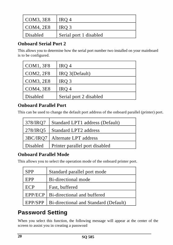
COM3, 3E8 IRQ 4COM4, 2E8 IRQ 3Disabled Serial port 1 disabled
Onboard Serial Port 2This allows you to determine how the serial port number two installed on your mainboardis to be configured.
COM1, 3F8 IRQ 4COM2, 2F8 IRQ 3(Default)COM3, 2E8 IRQ 3COM4, 3E8 IRQ 4Disabled Serial port 2 disabled
Onboard Parallel PortThis can be used to change the default port address of the onboard parallel (printer) port.
378/IRQ7 Standard LPT1 address (Default)278/IRQ5 Standard LPT2 address3BC/IRQ7 Alternate LPT addressDisabled Printer parallel port disabled
Onboard Parallel ModeThis allows you to select the operation mode of the onboard printer port.
SPP Standard parallel port modeEPP Bi-directional modeECP Fast, bufferedEPP/ECP Bi-directional and bufferedEPP/SPP Bi-directional and Standard (Default)
Password SettingWhen you select this function, the following message will appear at the center of thescreen to assist you in creating a password.

SQ 585 21
ENTER PASSWORD:Type the password, up to eight characters, and press <Enter>. The password typed nowwill clear any previously entered password from CMOS memory. You will be asked toconfirm the password. Type the password again and press <Enter>. You may also press<Esc> to abort the selection and not enter a password.
To disable password, just press <Enter> when you are prompted to enter password. Amessage will confirm the password being disabled. Once the password is disabled, thesystem will boot and you can enter Setup freely.
PASSWORD DISABLED.If you select System at Security Option of BIOS Features Setup Menu, you will beprompted for the password every time the system is rebooted or any time you try to enterSetup. If you select Setup at Security Option of BIOS Features Setup Menu, you will beprompted only when you try to enter Setup.
IDE HDD Auto DetectionBIOS setup will display all possible modes that supported by the HDD includingNORMAL, LBA & LARGE.
if HDD does not support LBA modes, no ‘LBA’ option will be shown.
if no of cylinders is less than or equal to 1024, no ‘LARGE’ option will be show
Users can select a mode which is appropriate for them.
SQ 58522
VGA Installation
Introduction
The SQ585 All-In -One Mainboard provide a compact video andgraphics solution for PC based system. It provides a high performance3-in-1 PCI true-color graphics accelerator with video acceleratefunctions. It works in five different modes: VESA VAFC (VESAAdvanced Feature Connector) mode, standard FC (Feature Connector)mode, SiS FC (SiS Proprietary Defined Feature Connector) mode,direct draw video mode, and PCI multimedia mode.
Features
Supports 32-bit PCI local bus standard Revision 2.1Supports PCI burst writeSupports PCI multi-function deviceFollows the one-load-per-slot PCI specificationSupports PCI multimedia design guide Rev. 1.0
Performance
Supports Turbo Queue Software Command Queue in off-screenmemory) architecture to achieve extra-high performance (patentpending)Built-in an enhanced 64-bit BITBLT graphics engine with thefollowing functions:
256 raster operation functionsRectangle fillColor/Font expansionEnhanced Color expansionEnhanced Font expansion

SQ 585 23
Line-drawing with styled patternBuilt-in 8x8 pattern registersBuilt-in 8x8 mask registers32 doublewords Command Queue
Built-in 64x64x2 bit-mapped hardware cursorBuilt-in 6 stages CPU write-buffer and 128 bits read-ahead cacheto minimize CPU wait-stateBuilt-in 2 stages engine write-buffer and 320 bits read-buffer tominimize engine wait-stateBuilt-in 64x24 CRT FIFOs to support super high resolutiongraphic modes and reduce CPU wait-stateMemory-mapped I/O to reduce I/O trapping overhead underprotected modeSupports linear addressing mode up to 4MByte to speed upgraphics performanceSupports shared memory for both system memory and displaymemory
Integration
Built-in programmable 24-bit true-color RAMDAC withreference-voltage generatorBuilt-in dual-clock generatorBuilt-in monitor-sense circuitBuilt-in graphics accelerator and VGA controllerBuilt-in video acceleratorBuilt-in PCI multimedia interfaceBuilt-in feature connector and baseline 16-bit VAFC logic

SQ 58524
Display Memory Interface
64-bit interleaved video memory data bus architecture with up to380 MByte/sec peak memory bandwidth by using 4 banks ofDRAM.Supports 256Kx4, 256Kx8, and 256Kx16 DRAM and EDODRAM typesSupports virtual screen up to 2048x2048Supports 80/132 columns text mode in 25, 30, 44 or 60 rows andother modesSupports 75Hz vertical refresh rate
Video Functions
Supports full motion picture required only 1 Megabyte DRAM andup to 1024x768x256 modeUses SiS proprietary defined 8-bit feature connector directconnecting to SiS 6204 for video overlaySupports single frame buffer architecture to save the DRAM costSupports graphics/video overlay function by color-key operationSupports multi-format Video For Windows such as YUV411,YUV422, ARGB8888, RGB888, RGB565, and RGB555Supports YUV-to-RGB color space conversionSupports video scaling in integer increments of 1/64Supports horizontal interpolation 1x, 2x, and 4xSupports vertical interpolation 1x, 2x, 3x for better quality ofvideo windows expansionBuilt-in 64x10 video capture FIFOs to support video captureBuilt-in 64x16 video playback FIFOs to support video playbackSupports Microsoft Video For WindowsReal-Magic MPEG API compatible for interactive title

SQ 585 25
Supports DCI Drivers
Multimedia Application
Supports DDC1 and DDC2B specificationsFollows the plug & play specification for display controllerSupports RAMDAC snoop for multimedia applications

SQ 58526
Software Drivers
To make use of the advance features of the VGA, extended graphicand text modes are supported by software application driversdeveloped by SiS. The following applications are currently supportedon a CDROM, the detail installation procedure please refer to thereadme file:
3D Studio Ver. 3.0AutoCAD/386 Release 11, 12Auto Shade/386 Ver. 2.0GEM 3.0/Ventura 2.0Lotus 1-2-3/Symphony Ver. 2.xMicroSoft Windows 3.1MicroSoft Windows NT Ver. 3.1 & 3.5MicroSoft Windows 95OrCad (SDT/VST/PCB) Rel 4OS/2 Presentation Manager 3.0P-CAD Ver. 6.06VersaCAD/386 Ver. 2.1Word Perfect 5.x & 6.0