basisinformationen mainboard basic information on … · basisinformationen mainboard basic...
TRANSCRIPT

Mainboard
Technisches Handbuch / Technical Manual
Deutsch - English
Basisinformationen Mainboard Basic information on mainboard

Sie haben ...
... technische Fragen oder Probleme? Wenden Sie sich bitte an: ● unsere Hotline:
Mo-Fr: 8 - 18 Uhr Sa: 9 - 14 Uhr Tel.: ++49 (0) 180 3777 000
● Ihren zuständigen Vertriebspartner oder Ihre Verkaufsstelle ● unsere Hotline über das Kontaktformular unter www.fujitsu-siemens.com/support/contact/
contact.html oder für Kunden, die ein einzelnes Mainboard gekauft haben: +49(0) 180 3777 005 Aktuelle Informationen und Updates (z. B. BIOS-Update) zu unseren Mainboards finden Sie im Internet: www.fujitsu-siemens.com/mainboards
Are there ...
... any technical problems or other questions you need clarified? Please contact: ● your sales partner or your sales outlet ● our hotline via the contact form at www.fujitsu-siemens.com/support/contact/contact.html, or for
customers who have purchased an individual mainboard: +49(0) 180 3777 005 The latest information and updates (e.g. BIOS update) on our mainboards can be found on the Internet under: www.fujitsu-siemens.com/mainboards


Dieses Handbuch wurde erstellt von cognitas. Gesellschaft für Technik-Dokumentation mbH – www.cognitas.de Dieses Handbuch wurde auf Recycling-Papier gedruckt. This manual has been printed on recycled paper. Ce manuel est imprimé sur du papier recyclé. Este manual ha sido impreso sobre papel reciclado. Questo manuale è stato stampato su carta da riciclaggio. Denna handbok är tryckt på recyclingpapper. Dit handboek werd op recycling-papier gedrukt. Herausgegeben von/Published by Fujitsu Siemens Computers GmbH Printed in the Federal Republic of Germany AG 08/05 Ausgabe/Edition 3 Bestell-Nr./Order No.: A26361-D2000-Z120-1-7419
A26361-D2000-Z120-1-7419

A26361-D2000-Z120-1-7419, edition 3 English
Contents Basisinformationen Mainboard......................................................................................................... 1
Notational conventions ................................................................................................................. 1 Important notes..................................................................................................................................... 2
Information about boards ............................................................................................................. 2 Special features............................................................................................................................ 3
Brief instructions on installing mainboard............................................................................................. 5 Prior to installation........................................................................................................................ 5
External ports ....................................................................................................................................... 7 Internal ports and connectors ............................................................................................................... 8
Audio front panel .......................................................................................................................... 8 AC97 Audio - 2, 4 or 6-channel audio mode ................................................................................ 8 High Definition Audio - 2, 4 or 6-channel audio mode................................................................ 10
Settings with switches and jumpers............................................................................................... 17 Switches and jumpers ........................................................................................................................ 17 Add-on modules / Upgrading .......................................................................................................... 19 Installing and removing processors .................................................................................................... 19
Socket type mPGA478, mPGA754 and mPGA939.................................................................... 19 Socket type LGA775................................................................................................................... 21
Upgrading main memory .................................................................................................................... 24 Replacing the lithium battery .............................................................................................................. 25 PCI slots ............................................................................................................................................. 26 Drivers ................................................................................................................................................ 26 BIOS update ....................................................................................................................................... 26 BIOS Recovery - Recovering System BIOS....................................................................................... 27 Microcode update (Intel processors only)........................................................................................... 28 Annex................................................................................................................................................. 29 Mainboard Revision and BIOS Version .............................................................................................. 29 Error messages .................................................................................................................................. 30 Glossary ............................................................................................................................................. 34


A26361-D2000-Z120-1-7419, edition 3 English - 1
Basisinformationen Mainboard This manual contains supplemental information to the "Short Description" manual of your mainboard. The mainboards are available in different configuration levels. Depending on your mainboard, you will not find several hardware components, although they are described in the manual. Details on your mainboard are contained in the "Short Description" manual.
Additional information Information on the BIOS Setup and additional descriptions of the drivers are contained: ● in the "BIOS Setup" manual on the CDs "Drivers & Utilities Collection", "Drivers & Utilities",
"ServerStart" or "User Documentation" ● in the readme files on your hard disk ● on the driver floppy disks included ● on the CDs "Drivers & Utilities Collection", "Drivers & Utilities", "ServerStart" or
"User Documentation".
i
The programme Acrobat Reader must be installed to be able to open the manuals. For more details please read the according readme.txt files.
Notational conventions The meanings of the symbols and fonts used in this manual are as follows:
!
indicates information which is important for your health or for preventing physical damage.
i
indicates additional information which is required to use the system properly.
► Text which follows this symbol describes activities that must be performed in the order shown.
└┘ This symbol indicates that you must enter a blank space (press the Space Bar) at this point. This symbol indicates that you must press the Enter key. Text in this typeface indicates screen outputs. Text in this bold typeface indicates the entries you make via the keyboard. Text in italics indicates commands or menu items. "Quotation marks" indicate names of chapters or terms.

Basisinformationen Mainboard
2 - English A26361-D2000-Z120-1-7419, edition 3
Important notes With the mainboard installed you must open the system to access the mainboard. How to dismantle and reassemble the system is described in the operating manual accompanying the system. Connecting cables for peripherals must be adequately shielded to avoid interference.
!
Observe the safety notes in the operating manual of your system. Incorrect replacement of the lithium battery may lead to a risk of explosion. It is therefore essential to observe the instructions in the "Add-on modules / Upgrading" - "Replacing the lithium battery" chapter. Components can become very hot during operation. Ensure you do not touch components when making extensions to the mainboard. There is a danger of burns!
The shipped version of this board complies with the requirements of the EEC directive 89/336/EEC "Electromagnetic compatibility". Compliance was tested in a typical PC configuration. When installing the board, refer to the specific installation information in the manual for the receiving device.
i
The warranty is invalidated if the system is damaged during the installation or replacement of expansions. Information on which expansions you can use is available from your sales outlet or the customer service centre.
Information about boards To prevent damage to the mainboard, the components and conductors on it, please take great care when you insert or remove boards. Take great care to ensure that extension boards are slotted in straight, without damaging components or conductors on the mainboard, or any other components, for example EMI spring contacts. Remove the plug from the mains outlet so that system and mainboard are totally disconnected from the mains voltage. Be careful with the locking mechanisms (catches, centring pins etc.) when you replace the mainboard or components on it, for example memory modules or processors. Never use sharp objects (screwdrivers) for leverage.
Boards with electrostatic sensitive devices (ESD) are identifiable by the label shown. When you handle boards fitted with ESDs, you must, under all circumstances, observe the following: ● You must always discharge static build up (e.g. by touching a grounded object)
before working. ● The equipment and tools you use must be free of static charges. ● Remove the power plug from the mains supply before inserting or removing
boards containing ESDs. ● Always hold boards with ESDs by their edges. ● Never touch pins or conductors on boards fitted with ESDs.

Basisinformationen Mainboard
A26361-D2000-Z120-1-7419, edition 3 English - 3
Special features Your mainboard is available in different configuration levels. Depending on your mainboard, the mainboard is equipped with or supports the features described in the following.
Silent Fan
A micro controller developed by Fujitsu Siemens Computers monitors and controls the fans in the PC and thus prevents any unnecessary noise annoyance. Should the processor become in spite of full turning ventilator too hot, then the processor clock rate will automatically be reduced so that the system continues to run stably. The microcontroller operates independently of the operating system and the processor. Therefore the micro controller protects your PC reliably against overheating and loss of data or even damage of the processor. In addition, the microcontroller offers monitoring of, for example, system voltages (12 V, 5 V, CMOS), opening of the case and a watchdog function.
Silent Fan LT
A controller regulates the processor fan in the PC and thus prevents unnecessary noise pollution. The controller operates independently of the operating system and the processor.
SystemGuard
With SystemGuard the function of the onboard Silent Fan Controller is displayed. SystemGuard indicates temperature, rotational speed of the fan and voltages, which are measured by the Silent Fan Controller. Moreover the software offers various setting options to optimise the noise level. SystemGuard is a freeware-tool, which is available on the internet.
Silent Drives
Hard disks and optical drives (CD-ROM, CD-RW, DVD etc.) are besides the fans some of the greatest sources of noise in a PC. The BIOS-Setup can be used to switch these drives into a quieter mode.
Recovery BIOS
If an error occurs during a BIOS update (e. g. due to a power failure), the system BIOS will be destroyed. All Fujitsu Siemens Computers mainboards are equipped with a recovery BIOS. With it a destroyed BIOS can easily be restored. Exact instructions are provided in the chapter "BIOS Recovery - Recovering System BIOS".

Basisinformationen Mainboard
4 - English A26361-D2000-Z120-1-7419, edition 3
DeskUpdate
DeskUpdate enables simple, automatic driver installation. The function is available both on the CD "Drivers & Utilities" and on the Internet.
Multi Boot
The BIOS of the Fujitsu Siemens Computers mainboards enables booting from all types mass storage devices. In addition to IDE hard disks, this also includes optical drives, such as CD-ROM, DVD and external drives that can be connected to USB or FireWire.
Safe Standby
With Safe Standby the content of the main memory is saved to the hard disk when the PC switches into the Standby mode. In case of an unexpected power failure, the content of the main memory is loaded during booting from the hard disk. Additional information is available on the Internet at www.fujitsu-siemens.com/manageability.
Harddisk Password
A password assignment for the hard disk is only possible with suitable hard disks and prevents unauthorised access to the stored data. For up to four hard disks one password each can be assigned in the BIOS-Setup (e. g. for up to four different users). Additional information is contained in the "BIOS Setup" manual.
Basisinformationen Mainboard
A26361-D2000-Z120-1-7419, edition 3 English - 5
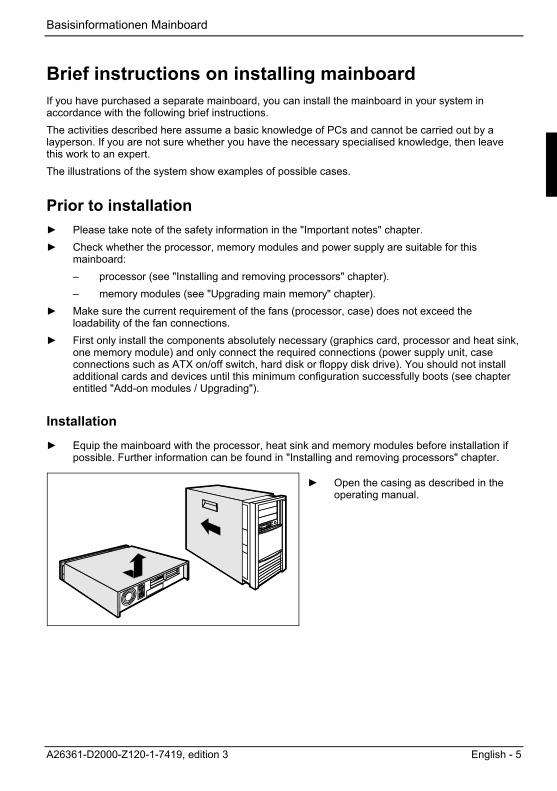
Brief instructions on installing mainboard If you have purchased a separate mainboard, you can install the mainboard in your system in accordance with the following brief instructions. The activities described here assume a basic knowledge of PCs and cannot be carried out by a layperson. If you are not sure whether you have the necessary specialised knowledge, then leave this work to an expert. The illustrations of the system show examples of possible cases.
Prior to installation ► Please take note of the safety information in the "Important notes" chapter. ► Check whether the processor, memory modules and power supply are suitable for this
mainboard: – processor (see "Installing and removing processors" chapter). – memory modules (see "Upgrading main memory" chapter).
► Make sure the current requirement of the fans (processor, case) does not exceed the loadability of the fan connections.
► First only install the components absolutely necessary (graphics card, processor and heat sink, one memory module) and only connect the required connections (power supply unit, case connections such as ATX on/off switch, hard disk or floppy disk drive). You should not install additional cards and devices until this minimum configuration successfully boots (see chapter entitled "Add-on modules / Upgrading").
Installation
► Equip the mainboard with the processor, heat sink and memory modules before installation if possible. Further information can be found in "Installing and removing processors" chapter.
► Open the casing as described in the
operating manual.

Basisinformationen Mainboard
6 - English A26361-D2000-Z120-1-7419, edition 3
► Should no suitable connection field be
provided in the case, then you must install the connection field (1) provided.
Ensure the plate is aligned properly so that the connections are suitable for the mainboard later. ► Set the mainboard on the edge on which
the connection field is located (2) and then insert the board in the case (3).
Make sure that spacers in the housing are only mounted at points at which there are mounting holes in the mainboard. ► Fasten the mainboard with the screws.
► Connect the plugs for the power supply, control panel and drives to the corresponding
connections on the mainboard.
Driver installation
► Install the drivers for the chipset. You may find the driver on the "Drivers & Utilities" CD. Please refer to chapter "Drivers" for a description of installing drivers.
Interfaces and connectors
The location of the connections and connectors of your mainboard is specified in the "Short Description" manual.

Basisinformationen Mainboard
A26361-D2000-Z120-1-7419, edition 3 English - 7
External ports The locations of the external connections are usually marked with the following symbols.
PS/2 keyboard port, purple
Audio input (Line in), light blue
Serial interface, turquoise
PS/2 mouse port, green
Monitor port, blue
Parallel port/Printer, burgundy
LAN
LAN port USB - Universal Serial Bus, black
Audio output (Line out), light green
Microphone jack (mono), pink
1394 FireWire, grey S/PDIF digital 6-channel audio output, orange

Basisinformationen Mainboard
8 - English A26361-D2000-Z120-1-7419, edition 3
Internal ports and connectors The location of the internal connections and connectors of your mainboard is specified in the "Short Description" manual.
Audio front panel If you want to use the internal connection for the audio front panel for the front side of the system, then proceed as follows: ► Remove all jumpers from the audio front panel connection, if present. ► Connect the cable for the audio front panel.
i
Only for mainboards with AC97 audio controller If you connect audio devices on both the front and the back of the system, you can only use the connections Line out and Microphone once each. If you have connected audio devices to both Line out connections, only the connection on the front of the system is active. If you have connected audio devices to both Microphone connections, only the connection on the back of the system is active.
AC97 Audio - 2, 4 or 6-channel audio mode Audio port front AC97 audio (black)
1 2
Pin Signal Pin Signal
1 Micro input 2 Analogue GND
3 Micro bias 4 Analogue VCC
5 Right line output 6 Right line return
7 not connected 8 Key
9 Left line output 10 Left line return
If the audio front panel is not used, you must plug the jumpers on pin pairs 5/6 and 9/10. When equipped with an AC97 audio controller, the mainboard can support a 6-channel audio output via the analogue audio channels (2 front, 2 rear, 1 centre and 1 subwoofer channel). This makes it possible to connect 4 or 6 loudspeakers, and therefore to achieve a better surround-sound effect.
i
Some mainboards with an AC97 audio controller only support stereo audio. The audio functions your mainboard supports are specified in the "Short Description" manual for your mainboard.

Basisinformationen Mainboard
A26361-D2000-Z120-1-7419, edition 3 English - 9
Drivers A corresponding driver must be installed for the 2, 4 or 6-channel audio mode. If the drive is not installed yet, proceed as described in the chapter "Add-on modules / Upgrading", in the section "Drivers".
Connecting loudspeakers The number of loudspeakers connected should match the number of audio channels you select in the driver software.
Using external audio connections
123
Analogue 2-channel audio output With the 2-channel configuration the functions Line-Out, Line-In and MIC are available.
1 = Line-In (blue) 2 = Line-Out (front channels, green) 3 = MIC (red)
123
Analogue 4-channel audio output Line-In is converted into the Rear-Out function with the 4-channel configuration.
1 = Line-In (rear channels, blue) 2 = Line-Out (front channels, green) 3 = MIC (red)
123
Analogue 6-channel audio output Line-In and MIC are converted into the function Line-Out with the 6-channel configuration.
1 = Line-In (rear channels, blue) 2 = Line-Out (front channels, green) 3 = MIC (centre and subwoofer channel, red)
i
Depending on driver version and operating system the functions may differ from this presentation. If necessary, further information is provided in the respective help system of drivers and software.
Selecting settings for 2, 4 or 6-channel audio mode
Depending on the driver for the audio mode and from the operating system used, you can configure the audio properties, e.g. with Windows 2000 under Start - Settings - Control Panel - Sounds and Multimedia.

Basisinformationen Mainboard
10 - English A26361-D2000-Z120-1-7419, edition 3
High Definition Audio - 2, 4 or 6-channel audio mode
Audio port front High Definition Audio (yellow)
1 2
Pin Signal Pin Signal
1 Micro input Left 2 Analogue GND
3 Micro input Right 4 Presence Detect
5 Right line / Headphone output
6 Sense 1 return
7 Jack sense Send 8 Key
9 Left line / Headphone output 10 Sense 2 return When equipped with a high-definition audio controller the mainboard can support an 8-channel audio output via the analogue audio channels (2 front, 2 side, 2 rear, 1 centre and 1 subwoofer channel). This makes it possible to connect up to 8 loudspeakers, and therefore to achieve a better surround-sound effect.
Drivers A corresponding driver including the configuration tool must be installed for the 2, 4, 6 or 8-channel audio mode. If the drive is not installed yet, proceed as described in the chapter "Add-on modules / Upgrading", in the section "Drivers".
Connecting loudspeakers The configuration tool detects the connection of loudspeakers for other audio devices. The Audio Wizard of the configuration tool assures itself by asking about each connected audio device. Follow the instructions on the screen. The number of connected loudspeakers must match the selected number of audio channels which you have set in the configuration tool (Speaker Configuration).
Special feature of sound recording To record sound of a connected audio device, proceed as follows: ► Connect the audio device if necessary. ► Answer the query of the Audio Wizard. ► Select the corresponding audio input for sound recording (see following table) as the standard
recording device (Control Panel - Sounds and Audio Devices - Audio tab). ► Select the corresponding Audio Input Mixer in the Windows volume control (Options - Audio
Properties). ► Set the desired recording level in the Windows volume control (for recordings).

Basisinformationen Mainboard
A26361-D2000-Z120-1-7419, edition 3 English - 11
The following mixers or input devices are available:
Realtek HD Front Green Jack Front (green) jack
Realtek HD Front Pink Jack Front (pink) jack
Realtek HD Audio Rear Input Rear (pink) jack (microphone) Rear (blue) jack (Line-In) Audio-In (internal jack on mainboard)
Front panel
Watch the poling of the LEDs. The positive pole of the connection cables is often indicated with a coloured wire.
1) Both jumper positions possible2) 2pin or 3pin connector possible3) optional
12
HD-LED
Power On/Off
Recovery Password
1)
Reset
Power OnLED 2)
Message LED
Speaker
3)
3)
Port Note Reset Connector for reset switch
Power On/Off Connection for ATX On/Off switch HD LED Indicates HDD (hard disk) activity
Message LED Optional: Indicates system management error Power On LED Indicates the system state APM or ACPI
Recovery see "Settings with switches and jumpers" chapter Password see "Settings with switches and jumpers" chapter Speaker Optional: 0,5 W at 8 Ohm
Pin Signal Pin Signal 1 GND 2 Speaker - 3 "Stand by" LED + 4 Key 5 Key 6 GND 7 "Power On" LED + 8 Speaker + 9 "Power On" LED + 10 Reserved
11 "Power On" LED - / "Stand by" LED - / (GND) 12 Reserved 13 "Message" LED + 14 Key 15 "Message" LED - 16 Password Skip 17 Key 18 GND 19 "HD" LED + 20 GND 21 "HD" LED - 22 Recover BIOS 23 GND 24 Key 25 Power-Button (low asserted) 26 GND 27 reserved 28 GND 29 Reset-Button (low asserted) 30 GND

Basisinformationen Mainboard
12 - English A26361-D2000-Z120-1-7419, edition 3
LCD display 2
1
Pin Signal Pin Signal 1 SMB CLK 8 LAN Link Icon 2 GND 9 Harddisk Action Icon 3 SMB DATA 10 BMC Alert Icon 4 GND 11 Message Icon 5 Key 12 Sleep Icon 6 RFU
Reserved for Future use 13 Power Icon
7 LAN Active Icon 14 P3V3P_DUAL
Audio In 1
Pin Signal 1 Left audio input 2 Analogue GND 3 Analogue GND 4 Right audio input
Audio S/PDIF (optional) 1
Pin Signal 1 VCC 2 SPDIF out 3 GND

Basisinformationen Mainboard
A26361-D2000-Z120-1-7419, edition 3 English - 13
Temperature sensor SMB 1
Pin Signal 1 P3V3P DUAL 2 SMB CLK 3 SMB DATA 4 GND
USB - dual channel
A = with chipcard reader support B = without chipcard reader support
1 2
11 12
3 4A B
Pin Signal Pin Signal 1 Key 2 Chipcard reader on
or not connected 3 VCC x 4 VCC y 5 Data negative x 6 Data negative y 7 Data positive x 8 Data positive y 9 GND 10 GND
11 Key 12 not connected
Fan
(only for 3 pin fans)
1
Pin Signal 1 GND 2 Controlled FAN voltage (0V, +6V, ... +12V, max. 1A)
or fix Fan voltage (+12 V, max. 1 A) 3 Fan sense

Basisinformationen Mainboard
14 - English A26361-D2000-Z120-1-7419, edition 3
Fan
(only for 4 pin fans)
1
Pin Signal 1 GND 2 +12 V 3 Fan sense 4 Fan control (PWM)
1394 connector (internal header) 1 2
Pin Signal Pin Signal 1 TPA+ 2 TPA- 3 GND 4 GND 5 TPB+ 6 TPB- 7 +12 V 8 +12 V 9 Key 10 GND
Power supply ATX 1
11
Pin Signal Pin Signal 1 +3.3V(P3V3P) 11 +3.3V(P3V3P) 2 +3.3V(P3V3P) 12 -12V (P12VN) 3 GND 13 GND 4 +5V (VCC) 14 PS on (low asserted) 5 GND 15 GND 6 +5V (VCC) 16 GND 7 GND 17 GND 8 Powergood (high asserted) 18 -5V (5PVN) 9 +5V Auxiliary (VCC Aux) 19 +5V (VCC)
10 +12V (P12VP) 20 +5V (VCC)

Basisinformationen Mainboard
A26361-D2000-Z120-1-7419, edition 3 English - 15
Power supply BTX
(ATX compatible)
1
13
24-Pin BTX connector
Pin Signal Pin Signal 1 +3.3 V (P3V3P) 13 +3.3 V (P3V3P) 2 +3.3 V (P3V3P) 14 -12 V (P12VN) 3 GND 15 GND 4 +5V (VCC) 16 PS on (low asserted) 5 GND 17 GND 6 +5V (VCC) 18 GND 7 GND 19 GND 8 Powergood (high asserted) 20 -5 V (P5VN) 9 +5 V Auxiliary (VCC Aux) 21 +5 V (VCC)
10 +12 V (P12VP) 22 +5 V (VCC) 11 +12 V (P12VP) 23 +5 V (VCC) 12 +3.3 V (P3V3P) 24 GND
24-Pin connector for D216x
i
Do not connect this connector with a standard power supply!
Pin Signal Pin Signal 1 +3.3 V (P3V3P) 13 +3.3 V (P3V3P) 2 +3.3 V (P3V3P) 14 -12 V (P12VN) 3 GND 15 GND 4 +5V (VCC) 16 PS on (low asserted) 5 GND 17 GND 6 +5V (VCC) 18 GND 7 GND 19 GND 8 Powergood (high asserted) 20 -5 V (P5VN) 9 +5 V Auxiliary (VCC Aux) 21 +5 V (VCC)
10 +12 V (P12VP) 22 +5 V (VCC) 11 Fan sense 23 GND 12 Fan PWM 24 Power Supply Monitoring
Basisinformationen Mainboard
16 - English A26361-D2000-Z120-1-7419, edition 3
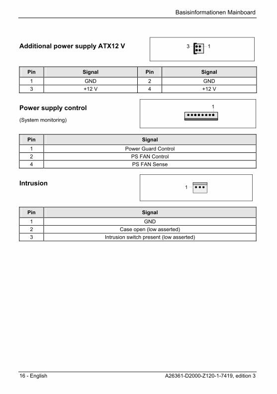
Additional power supply ATX12 V 13
Pin Signal Pin Signal 1 GND 2 GND 3 +12 V 4 +12 V
Power supply control
(System monitoring)
1
Pin Signal 1 Power Guard Control 2 PS FAN Control 4 PS FAN Sense
Intrusion 1
Pin Signal 1 GND 2 Case open (low asserted) 3 Intrusion switch present (low asserted)

A26361-D2000-Z120-1-7419, edition 3 English - 17
Settings with switches and jumpers Switches and jumpers Your mainboard is optionally equipped with switches or jumpers. The location of the switches or jumpers is specified in the "Short Description" manual.
Setting with switches
1 2 3 4
ONSwitch 1 = Skipping system and BIOS Setup password Switch 2 = System BIOS recovery Switch 3 = must be set to off Switch 4 = must be set to off
Setting with jumpers
21
SKP RCV
Pin pair 1 inserted = Skipping system and BIOS Setup password Pin pair 2 inserted = System BIOS recovery Any other setting = State of supply; jumper has no function
Setting via control-panel plug connector
A
C 12
12
B 12
Pin pair A inserted = Skipping system and BIOS Setup password Pin pair B inserted = System BIOS recovery Pin pair C inserted = factory setting
i
Please pay attention on the exact position of the pin pairs!

Settings with switches and jumpers
18 - English A26361-D2000-Z120-1-7419, edition 3
Skipping system and BIOS Setup password - switch 1 / pin pair 1 / pin pair A Switch 1 / pin pair 1 / pin pair A enables skipping the system and BIOS Setup password. Inserted System and BIOS Setup password are skipped when the device is switched on and
may be changed. Not inserted System and BIOS Setup password must be entered when the device is switched on.
Recovering System BIOS - switch 2 / pin pair 2/ pin pair B Switch 2 / pin pair 2 / pin pair B enables recovery of the old system BIOS after an attempt to update has failed. To restore the old BIOS you need a Flash BIOS Diskette (see "BIOS update" chapter). Inserted The System BIOS executes from floppy drive A: and the inserted "Flash-BIOS-
Diskette" restores the System BIOS on the mainboard. Not inserted Normal operation (default setting).
Reserved - switch 3 and switch 4 (if present) Switch 3 and 4 are reserved. The position of the switch doesn't matter.
A26361-D2000-Z120-1-7419, edition 3 English - 19
Add-on modules / Upgrading
!
Exit energy-saving mode, switch off the system and remove the power plug from the mains outlet, before carrying out any of the procedures described in this chapter! Even when you have run down the device, parts of the device (e.g. memory modules, PCI extension boards) are still energised.
Installing and removing processors There are different socket types for the processor, resulting in different procedures for processor installation and removal.
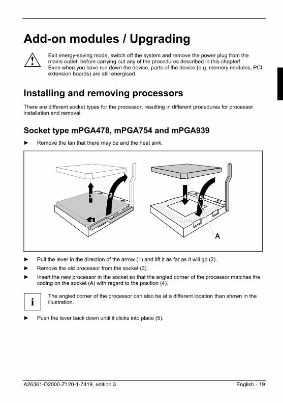
Socket type mPGA478, mPGA754 and mPGA939 ► Remove the fan that there may be and the heat sink.
3 2
1
A
4 53 2
1
A
4 5
► Pull the lever in the direction of the arrow (1) and lift it as far as it will go (2). ► Remove the old processor from the socket (3). ► Insert the new processor in the socket so that the angled corner of the processor matches the
coding on the socket (A) with regard to the position (4).
i
The angled corner of the processor can also be at a different location than shown in the illustration.
► Push the lever back down until it clicks into place (5).

Add-on modules / Upgrading
20 - English A26361-D2000-Z120-1-7419, edition 3
Mounting heat sink
Be sure to use heat conducting material between the processor and the heat sink. If a heat conducting pad (rubber-like foil) is already applied to the heat sink, then use it. Otherwise you must apply a very thin layer of heat conducting paste. Heat conducting pads can only be used once. If you remove the heat sink, you must clean it and apply new heat conducting paste before you remount it. Please note that, depending on the heat sink used, different heat sink mounts are required on the mainboard.
i
If a counter-plate is mounted on the underside of the mainboard for reinforcement, no heat sinks of the type "Intel Boxed" may be used. Otherwise the retaining clips of the heat sink will be damaged. When using an "Intel Boxed" heat sink, the mainboard must be converted. The conversion kit is either included with the mainboard or is available separately. If no counter-plate is mounted, you can use both "Intel Boxed" heat sinks and standard heat sinks. If you use the "Intel Boxed" heat sink, the mainboard will bend due to the high pressure of the retaining clips. This behaviour is specified by Intel.
► Depending on the configuration variant, you
must pull a protective foil off the heat sink or coat the heat sink with heat conducting paste before fitting it.
Depending on the processor variant, clips may also be supplied for mounting the heat sink that fix it in place. Ê When you have mounted the optional fan,
connect the fan plug to the corresponding connection on the mainboard.

Add-on modules / Upgrading
A26361-D2000-Z120-1-7419, edition 3 English - 21
Socket type LGA775
!
The processor socket ist covered with a protective cap to protect the spring contacts In a warranty case the mainboard can only be taken back by Fujitsu Siemens Computers with the protective cap secured! Never touch the underside of the processor. Even minor soiling such as grease from the skin can impair the processor's operation or destroy the processor. Place the processor in the socket with extreme care, as the spring contacts of the socket are very delicate and must not be bent.
► Remove the heat sink.
1
2
► Press down the lever (1) and unhook it (2). ► Fold up the frame.
3
► Remove the old processor (3) from the socket.

Add-on modules / Upgrading
22 - English A26361-D2000-Z120-1-7419, edition 3
a
b
b
Hold the new processor between your thumb and index finger and insert it into the socket (b) so that the marking of the processor is aligned with the marking on the socket (a).
1
2
3
► Fold down the frame (1). ► Press the lever downward (2) until it is hooked
in again. ► Remove the protective cap (3) and keep it.

Add-on modules / Upgrading
A26361-D2000-Z120-1-7419, edition 3 English - 23
Mounting heat sink
i
Use only the heat sink supplied with your system!
Be sure to use heat conducting material between the processor and the heat sink. If a heat conducting pad (rubber-like foil) is already applied to the heat sink, then use it. Otherwise you must apply a very thin layer of heat conducting paste. Heat conducting pads can only be used once. If you remove the heat sink, you must clean it and apply new heat conducting paste before you remount it.
2
2
22
2
1
► Depending on the configuration variant, you
must pull a protective foil off the heat sink or coat the heat sink with heat conducting paste before fitting it.
► Secure the heat sink - depending on the model - with four screws or push it into the mounts.
Add-on modules / Upgrading
24 - English A26361-D2000-Z120-1-7419, edition 3
Upgrading main memory Information on equipment, memory modules, module sizes and memory expansion is contained in the "Short Description" manual. A current list of the memory modules recommended for this mainboard is available on the Internet at: www.fujitsu-siemens.com.
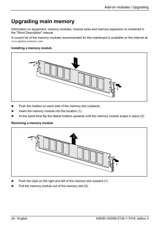
Installing a memory module
2
2
► Push the holders on each side of the memory slot outwards. ► Insert the memory module into the location (1). ► At the same time flip the lateral holders upwards until the memory module snaps in place (2).
Removing a memory module
1
1
► Push the clips on the right and left of the memory slot outward (1). ► Pull the memory module out of the memory slot (2).
Add-on modules / Upgrading
A26361-D2000-Z120-1-7419, edition 3 English - 25
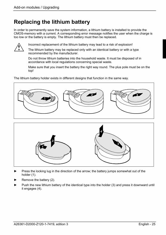
Replacing the lithium battery In order to permanently save the system information, a lithium battery is installed to provide the CMOS-memory with a current. A corresponding error message notifies the user when the charge is too low or the battery is empty. The lithium battery must then be replaced.
!
Incorrect replacement of the lithium battery may lead to a risk of explosion! The lithium battery may be replaced only with an identical battery or with a type recommended by the manufacturer. Do not throw lithium batteries into the household waste. It must be disposed of in accordance with local regulations concerning special waste. Make sure that you insert the battery the right way round. The plus pole must be on the top!
The lithium battery holder exists in different designs that function in the same way.
2 3
31
2
4
► Press the locking lug in the direction of the arrow; the battery jumps somewhat out of the
holder (1). ► Remove the battery (2). ► Push the new lithium battery of the identical type into the holder (3) and press it downward until
it engages (4).

Add-on modules / Upgrading
26 - English A26361-D2000-Z120-1-7419, edition 3
PCI slots Die meisten von Fujitsu Siemens Computers entwickelten Mainboards entsprechen der Intel Spezifikation Revision 2.3. Es können weiterhin 5V PCI-Karten in den PCI-Steckplätzen verwendet werden. Die Verlustleistung von 25 W darf dabei nicht überschritten werden.
Drivers Only when no drivers are installed on your system, or you want to update these, proceed as follows: ► Insert the CD "Drivers & Utilities Collection" into the CD-ROM drive. ► If the CD does not start automatically, run the START.EXE programme in the main directory of
the CD. ► Select DeskUpdate - Fully automatic installation. ► Follow the instructions on screen.
BIOS update When should a BIOS update be carried out? Fujitsu Siemens Computers makes new BIOS versions available to ensure compatibility to new operating systems, new software or new hardware. In addition, new BIOS functions can also be integrated. A BIOS update should always also be carried out when a problem exists that cannot be solved with new drivers or new software. Where can I obtain BIOS updates? The BIOS updates are available on the Internet at www.fujitsu-siemens.com/mainboards. How does a BIOS update work? You have two ways of doing this:
1. BIOS update under DOS with bootable BIOS update floppy disk - brief description ► Download the update file from out website to your PC. ► Insert an empty floppy disk (1.44 MB). ► Run the update file (e.g. 1858103.EXE). ► A bootable update floppy disk is created. Leave this floppy disk in the drive. ► Restart the PC. ► Follow the instructions on screen.
i
Detailed information on the BIOS Setup and the BIOS update under DOS is contained in the "BIOS Setup" manual (on the "Drivers & Utilities Collection", "Drivers & Utilities", "ServerStart" or "User Documentation" CDs).
2. BIOS update under Windows with DeskFlash utility A BIOS update can also be carried out directly under Windows with the DeskFlash utility. DeskFlash is contained on the "Drivers & Utilities" CD (under DeskUpdate).

Add-on modules / Upgrading
A26361-D2000-Z120-1-7419, edition 3 English - 27
BIOS Recovery - Recovering System BIOS
i
All BIOS settings are reset to the default values.
► Open the casing as described in the operating manual. ► On the mainboard set the jumper to the appropriate setting to restore the system BIOS (see
chapter "Settings with switches and jumpers"). ► Close the casing as described in the operating manual. ► Insert a BIOS update floppy disk and start the PC. ► Note the signals issued from the loudspeaker. You have successfully restored the BIOS if you
hear the signal sequence "short-short- long- long- long" and the diskette access indicator is dark. This can take a few minutes.
► Open the casing as described in the operating manual. ► Restore the switch or jumper settings. ► Close the casing as described in the operating manual. ► Remove the floppy disk from the drive. ► Start the PC and invoke BIOS Setup. ► Select the menu item Reset Configuration in the menu Advanced and change the setting to Yes. ► Save the change and terminate BIOS Setup. The BIOS recovery has now been completed. The system restarts.
i
Detailed information on the BIOS Setup and the BIOS recovery is contained in the "BIOS Setup" manual (on the "Drivers & Utilities Collection", "Drivers & Utilities", "ServerStart" or "User Documentation" CDs).

Add-on modules / Upgrading
28 - English A26361-D2000-Z120-1-7419, edition 3
Microcode update (Intel processors only) What is a microcode update? As there are no drivers for processors, Intel offers the possibility from the P6 family (Pentium Pro) on to update the command set (microcode) of the processor. This enables minor errors to be corrected and the performance to be increased. To guarantee the best possible performance and error-free operation, Intel recommends updating the microcode for every new processor. Intel refers to the use of the processor without microcode updates as operation outside the specifications.
Safety for processor on Fujitsu Siemens Computers mainboards If the processor uses an old or incorrect microcode, error-free operation cannot be ensured. Fujitsu Siemens Computers has therefore implemented a function on its mainboards that interrupts the booting process if no suitable microcode is available for the installed processor. The output error message is Patch for installed CPU not loaded. Please run the bios flash update diskette.
This message appears until the microcode update has been carried out. If the computer is nevertheless operated without a microcode update, error-free operation is not ensured.
When should a microcode update be carried out? A microcode update should be carried out after the installation of a new processor. In contrast to the BIOS update, only an updated version of the processor command set is stored. The system BIOS remains unaffected by this.
Microcode update under DOS with bootable microcode update floppy disk - brief description ► Download the update file from out website to your PC. ► Insert an empty floppy disk (1.44 MB). ► Run the update file under DOS (e.g. 1858101.EXE). ► A bootable update floppy disk is created. Leave the floppy disk in the drive. ► Restart the PC. ► Follow the instructions on screen. To determine whether the latest microcode update has been loaded, the so-called Patch-ID of the processor can be read out. ► Press the F1 key in the BIOS Setup. The entry CPU / Patch ID is shown on the displayed information page. A list with the current processors and the related Patch-IDs is available on the Internet.
i
If the processor is not recognised, you also require the microcode update tool for processors of the P6 family.

A26361-D2000-Z120-1-7419, edition 3 English - 29
Annex Mainboard Revision and BIOS Version The compatibility, e.g. with new processors, can be independent of the BIOS version or the revision status of the mainboard used. The CPU and BIOS compatibility lists are available on the Internet at www.fujitsu-siemens.com/mainboards.
Mainboard Revision The revision status of the mainboard exactly identifies which mainboard you have. It is indicated on a sticker on the edge of the mainboard:
D1885-A11 GS 1
05618476
Example Mainboard-Revision
BIOS version The BIOS version can be displayed in the BIOS Setup. ► Press F2 during booting to open the BIOS Setup. ► Press F1 . The BIOS version is specified on the displayed information page under the entry BIOS Release.

Annex
30 - English A26361-D2000-Z120-1-7419, edition 3
Error messages This chapter contains error messages generated by the mainboard. Available CPUs do not support the same bus frequency - System halted! Memory type mixing detected Non Fujitsu Siemens Memory Module detected - Warranty void There are more than 32 RDRAM devices in the system
Check whether the system configuration has changed. If necessary, correct the settings. BIOS update for installed CPU failed
This message appears if the microcode update required for the connected processor is not contained in the system BIOS.
► Boot the system with the inserted Flash BIOS floppy disk. ► Abort the normal Flash BIOS update by answering the question about whether you want to
perform the update with n
► To carry out the Flash BIOS update for the processor, enter: flashbio└┘/p6
Check date and time settings
The system date and time are invalid. Set the current date and time in the Main menu of the BIOS Setup.
CPU ID 0x failed
Switch the server off and on again. If the message is still displayed, go into the BIOS setup and set the corresponding processor to Disabled in the Server - CPU Status menu; please contact your sales outlet or customer service centre.
CPU mismatch detected
You have replaced the processor or changed the frequency setting. As a result, the characteristic data of the processor have changed. Confirm this change by running the BIOS Setup and exiting it again.
Diskette drive A error Diskette drive B error
Check the entry for the diskette drive in the Main menu of the BIOS Setup. Check the connections to the diskette drive.
Annex
A26361-D2000-Z120-1-7419, edition 3 English - 31
DMA test failed EISA CMOS not writable Extended RAM Failed at offset: nnnn Extended RAM Failed at address line: nnnn Failing Bits: nnnn Fail-Safe Timer NMI failed Multiple-bit ECC error occurred Memory decreased in size Memory size found by POST differed from EISA CMOS Single-bit ECC error occurred Software NMI failed System memory exceeds the CPU’s caching limit System RAM Failed at offset: nnnn Shadow RAM Failed at offset: nnnn
Switch the device off and on again. If the message is still displayed, please contact your sales outlet or customer service centre.
Failure Fixed Disk 0 Failure Fixed Disk 1 Fixed Disk Controller Failure
Check the entry for the hard disk drive in the Main menu and the entry for the IDE drive controller in the Advanced - Peripheral Configuration menu of the BIOS Setup. Check the hard disk drive's connections and jumpers.
Incorrect Drive A - run SETUP Incorrect Drive B - run SETUP
Correct the entry for the diskette drive in the Main menu of the BIOS Setup. Invalid NVRAM media type
Switch the device off and on again. If the message is still displayed, please contact your sales outlet or customer service centre.
Invalid System Configuration Data
In the Advanced menu of the BIOS Setup set the entry Reset Configuration Data to Yes. Invalid System Configuration Data - run configuration utility Press F1 to resume, F2 to Setup
This error message may be displayed if the machine was switched off during system start-up. Call BIOS Setup and switch to the Advanced menu. Select the menu item Reset Configuration Data and change the setting to Yes. Save the change and terminate BIOS Setup. Reboot the device.
Keyboard controller error
Connect another keyboard or another mouse. If the message is still displayed, please contact your sales outlet or customer service centre.
Keyboard error
Check that the keyboard is connected properly.

Annex
32 - English A26361-D2000-Z120-1-7419, edition 3
Keyboard error nn nn Stuck Key
Release the key on the keyboard (nn is the hexadecimal code for the key). Missing or invalid NVRAM token
Switch the device off and on again. If the message is still displayed, please contact your sales outlet or customer service centre.
Monitor type does not match CMOS - RUN SETUP
Correct the entry for the monitor type in the Main menu of the BIOS Setup. On Board PCI VGA not configured for Bus Master
In the BIOS Setup, in the Advanced menu, submenu PCI Configuration, set the Shared PCI Master Assignment entry to VGA.
One or more RDRAM devices are not used One or more RDRAM devices have bad architecture/timing One or more RDRAM devices are disabled
Contact your system administrator or contact our customer service centre. Operating system not found
Check the entries for the hard disk drive and the floppy disk drive in the Main menu and the entries for Boot Sequence submenu of the BIOS Setup.
Parity Check 1 Parity Check 2
Switch the device off and on again. If the message is still displayed, please contact your sales outlet or customer service centre.
Previous boot incomplete - Default configuration used
By pressing function key F2 you can check and correct the settings in BIOS Setup. By pressing function key F1 the system starts with incomplete system configuration. If the message is still displayed, please contact your sales outlet or customer service centre.
Real time clock error
Call the BIOS Setup and enter the correct time in the Main menu. If the message is still displayed, please contact your sales outlet or customer service centre.
System battery is dead - Replace and run SETUP
Replace the lithium battery on the mainboard and redo the settings in the BIOS Setup. System Cache Error - Cache disabled
Switch the device off and on again. If the message is still displayed, please contact your sales outlet or customer service centre.
System CMOS checksum bad - Default configuration used
Call the BIOS Setup and correct the previously made entries or set the default entries.

Annex
A26361-D2000-Z120-1-7419, edition 3 English - 33
System Management Configuration changed or Problem occurred
A system fan or system sensor has failed. Check the hardware operation. System timer error
Switch the device off and on again. If the message is still displayed, please contact your sales outlet or customer service centre.
Uncorrectable ECC DRAM error DRAM Parity error Unknown PCI error
Switch the device off and on again. If the message is still displayed, please contact your sales outlet or customer service centre.
Verify CPU frequency selection in Setup
The frequency setting for the processor is invalid. Correct the BIOS Setup and the setting.

Annex
34 - English A26361-D2000-Z120-1-7419, edition 3
Glossary The technical terms and abbreviations given below represent only a selection of the full list of common technical terms and abbreviations. Not all technical terms and abbreviations listed here are valid for the described mainboard. AC'97 Audio Codec '97
ACPI Advanced Configuration and Power Management Interface
AOL Alert On LAN
APM Advanced Power Management
ATA Advanced Technology Attachment
BIOS Basic Input Output System
BMC Baseboard management controller
CAN Controller Area Network
CPU Central Processing Unit
DIMM Dual Inline Memory Module
ECC Error Correcting Code
EEPROM Electrical Erasable Programmable Read Only Memory
FDC Floppy disk controller
FIFO First-In First-Out
FSB Front Side Bus
FWH Firmware Hub
GMCH Graphics and Memory Controller Hub
GPA Graphics Performance Accelerator
I2C Inter Integrated Circuit
IAPC Instantly Available Power Managed Desktop PC Design
ICH I/O Controller Hub
IDE Intelligent Drive Electronics
IPSEC Internet Protocol Security
LAN Local Area Network
LSA LAN Desk Service Agent
MCH Memory Controller Hub
MMX MultiMedia eXtension
P64H PCI64 Hub
PCI Peripheral Component Interconnect
PCI Express Peripheral Component Interconnect Express
PXE Preboot eXecution Environment
RAM Random Access Memory
RAMDAC Random Access Memory Digital Analogue Converter
RTC Real Time Clock
SATA Serial Advanced Technology Attachment
SB Soundblaster
SDRAM Synchronous Dynamic Random Access Memory
SIMD Streaming Mode Instruction (Single Instruction Multiple Data)
SMBus System Management Bus
SVGA Super Video Graphic Adapter
USB Video Graphic Adapter
WOL Wake On LAN