sportsman 400/500 - tradebit · pdf file2005 sportsman 400/500 service manual foreword this...
TRANSCRIPT
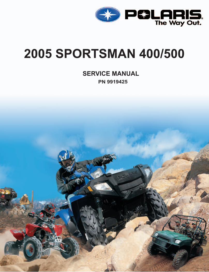
SPORTSMAN 400/500
99194
25
2005 S
PO
RT
SM
AN
400/5
00
25
9919425
SPORTSMAN 400/500
991949919425
Cvr_9919425 7/28/04 10:19 AM Page 1
2005 SPORTSMAN 400/500SERVICE MANUAL
ForewordThis manual is designed primarily for use by Polaris ATV service technicians in a properly equipped shop.Persons using this manual should have a sound knowledge of mechanical theory, tool use, and shop proce-dures in order to perform the work safely and correctly. The technician should read the text and be familiarwith service procedures before starting the work. Certain procedures require the use of special tools. Useonly the proper tools, as specified. Cleanliness of parts and tools as well as the work area is of primary impor-tance.All references to left and right side of the vehicle are from the operator’s perspective when seated in a normalriding position.This manual includes procedures for maintenance operations, component identification and unit repair, alongwith service specifications for the 2005 Polaris Sportsman ATVs. A table of contents is placed at thebeginning of each chapter, and an alphabetic index is provided at the end of the manual for location of specificpage numbers and service information. Keep this manual available for reference in the shop area.At the time of publication all information contained in this manual was technically correct. However, allmaterials and specifications are subject to change without notice.Comments or suggestions about this manual may be directed to: Polaris Sales Inc., Service PublicationsDepartment, 2100 Hwy 55 Medina, Minnesota 55340.
2005 Sportsman 400/500 ATV Service Manual (PN 9919425)ECopyright 2004 Polaris Sales Inc. All information contained within this publication is based on the latest product information at thetime of publication. Due to constant improvements in the design and quality of production components, some minor discrepancies mayresult between the actual vehicle and the information presented in this publication. Depictions and/or procedures in this publication areintended for reference use only. No liability can be accepted for omissions or inaccuracies. Any reprinting or reuse of the depictionsand/or procedures contained within, whether whole or in part, is expressly prohibited. Printed in U.S.A.

UNDERSTANDING SAFETY LABELS AND INSTRUCTIONS
Throughout these instructions, important information is brought to your attention by the following symbols:
The Safety Alert Symbol means ATTENTION! BECOME ALERT! YOUR SAFETY IS INVOLVED!
DANGER
Failure to follow DANGER instructions will result in severe injury or death to the operator, bystander or personinspecting or servicing the ATV.
WARNING
Failure to follow WARNING instructions could result in severe injury or death to the operator, bystander orperson inspecting or servicing the ATV.
CAUTION:
A CAUTION indicates special precautions that must be taken to avoid personal injury, or ATV or propertydamage.
NOTE:
A NOTE provides key information to clarify instructions.
Trademarks
Polaris acknowledges the following products mentioned in this manual:
FLEXLOC, Registered Trademark of SPS TechnologiesLoctite, Registered Trademark of the Loctite CorporationNyogel, Trademark of Wm. F. Nye Co.Fluke, Registered Trademark of John Fluke Mfg. Co.Mity Vac, Registered Trademark of Neward Enterprises, Inc.Torx, Registered Trademark of TextronHilliard, Trademark of the Hilliard CorporationWarn, Trademark of the Warn Industries
Some Polaris factory publications can be downloaded from www.polarisindustries.com or purchased fromwww.purepolaris.com or contact your nearest Polaris dealer.

GENERAL
MAINTENANCE
ENGINE
CARBURETION
CLUTCHING
FINAL DRIVE
BODY AND STEERING
TRANSMISSION
BRAKES
ELECTRICAL
GENERAL INFORMATION
1.1
Model Identification 1.2. . . . . . . . . . . . . . . . . . . . . . .
Serial Number Location 1.2. . . . . . . . . . . . . . . . . . .
Publication Numbers 1.3. . . . . . . . . . . . . . . . . . . . .
Paint Codes 1.3. . . . . . . . . . . . . . . . . . . . . . . . . . . . .Replacement Keys 1.3. . . . . . . . . . . . . . . . . . . . . . .
General Specifications - Sportsman 400/500 1.4-1.6.
Special Tools 1.7--1.12. . . . . . . . . . . . . . . . . . . . . . . . . . . .
Standard Torque Specifications 1.13. . . . . . . . . . . .
Decimal Equivalent Chart 1.14. . . . . . . . . . . . . . . . .
Conversion Table 1.15. . . . . . . . . . . . . . . . . . . . . . . .Glossary of Terms 1.16. . . . . . . . . . . . . . . . . . . . . . . .
Specs

GENERAL INFORMATION
1.2
MODEL IDENTIFICATIONThe machine model number must be used with any correspondence regarding warranty or service.
Machine Model Number Identification
Year Designation Basic ChassisDesignation Engine Designation
A 0 5 M H 5 0 A A
Model Option
ENGINE DESIGNATION NUMBERS42 EH42PLE Single, L/C, SOHC 4 Stroke, Electric Start. . . . . . . . . . . . . . .50 EH50PLE Single, L/C, SOHC 4 Stroke, Electric Start. . . . . . . . . . . . . . .
VIN IDENTIFICATION
1 2 3 4 5 6 7 8 9 10 11 12 13 14 15 16 174 X A M H 5 0 A * 5 P 0 0 0 0 0 0
Vehicle Descriptor Vehicle Identifier
Powertrain
EngineEmissions Model
YearPlant No.
Individual Serial No.Body Style
Check Digit
World Mfg. ID
* This could be eithera number or a letter
Whenever corresponding about an engine, be sure to refer to the engine model number and serial number. Thisinformation can be found on the sticker applied to the recoil housing on the right side of engine.(A) An additionalnumber is stamped on the center top of crankcase beneath the cylinder coolant elbow.
MACHINE MODEL NUMBER AND SERIAL NUMBER LOCATIONEngine model number is on recoil housing (A). Themachine model number and serial number areimportant for vehicle identification. The machineserial number is stamped on the lower left side ofthe frame tube.(B)
TRANSMISSION I.D. NUMBERLOCATION
A
BFront
The transmission I.D. number is lo-cated on top of the transmissionsnorkel, right side of machine.

GENERAL INFORMATION
1.3
PUBLICATION NUMBERS
Year Model Owner’s Manual PN PartsManual PN
PartsMicro Fiche PN
2005 Sportsman 400 9919412 9919413 9919414
2005 Sportsman 500 9919412 9919416 9919417
NOTE: When ordering service parts be sure to use the correct parts manual.NOTE: Some manuals can be found at the Polaris website: www.polarisindustries.com
ATV PAINT INFORMATIONFRAME COLOR - (All) P067 Medium Gloss Black 9440 / 8520147.
COLD WEATHER KITS FOR 4 CYCLE ATVSEngine Heater -- (PN 2871507)
ACCESSORY ENGINE HEATER
REPLACEMENT KEYSReplacement keys can be made from the originalkey. To identify which series the key is, take thefirst two digits on the original key and refer to thechart to the right for the proper part number.
Series # Part Number20 4010278
21 4010278
22 4010321
23 4010321
27 4010321
28 4010321
31 4110141
32 4110148
67 4010278
68 4010278
31XX
Key SeriesNumber

GENERAL INFORMATION
1.4
MODEL: 2005 Sportsman 400. . . . . . . . . .MODEL NUMBER: A05MH42.ENGINE MODEL: 425. .
Category Dimension
Length 83 in./211 cm
Width 48 in./122 cm
Height 48 in./122 cm
Wheel Base 51 in./129.5 cm
Ground Clearance 11 in./27.94 cm
Dry Weight 703 lbs./319 kg
Gross Vehicle Weight 1210 lbs./549 kg
Oil Capacity 2.25 qts./2.1 ltr
Coolant Capacity 2.25 qts./2.1 ltr
Front Rack Capacity 90 lbs./40.8 kg
Rear Rack Capacity 180 lbs./81.6 kg
Towing Capacity 1225 lbs./555.6 kg
Hitch Tongue Weight 120 lbs./54.4 kg
Body Style SPIRIT
MODEL: 2005 Sportsman 500. . . . . . . . . .MODEL NUMBER: A05MH50.ENGINE MODEL: 500. .
Category Dimension
Length 83 in./211 cm
Width 48 in./122 cm
Height 48 in./122 cm
Wheel Base 51 in./129.5 cm
Ground Clearance 11.25 in./28.6 cm
Dry Weight 715 lbs./324 kg
Gross Vehicle Weight 1222 lbs./554 kg
Oil Capacity 2.25 qts./2.1 ltr
Coolant Capacity 2.25 qts./2.1 ltr
Front Rack Capacity 90 lbs./40.8 kg
Rear Rack Capacity 180 lbs./81.6 kg
Towing Capacity 1225 lbs./555.6 kg
Hitch Tongue Weight 120 lbs./54.4 kg
Body Style SPIRIT
GENERAL INFORMATION
1.5
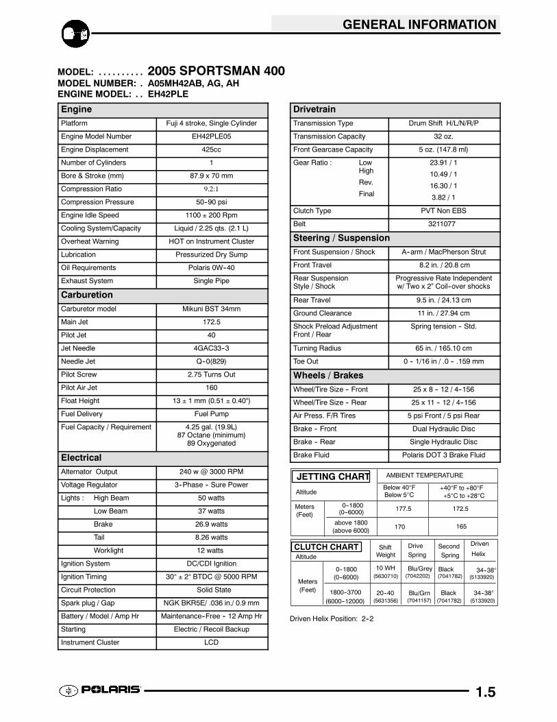
MODEL: 2005 SPORTSMAN 400. . . . . . . . . .MODEL NUMBER: A05MH42AB, AG, AH.ENGINE MODEL: EH42PLE. .
EnginePlatform Fuji 4 stroke, Single Cylinder
Engine Model Number EH42PLE05
Engine Displacement 425cc
Number of Cylinders 1
Bore & Stroke (mm) 87.9 x 70 mm
Compression Ratio 9.2:1
Compression Pressure 50--90 psi
Engine Idle Speed 1100 ± 200 Rpm
Cooling System/Capacity Liquid / 2.25 qts. (2.1 L)
Overheat Warning HOT on Instrument Cluster
Lubrication Pressurized Dry Sump
Oil Requirements Polaris 0W--40
Exhaust System Single Pipe
CarburetionCarburetor model Mikuni BST 34mm
Main Jet 172.5
Pilot Jet 40
Jet Needle 4GAC33--3
Needle Jet Q--0(829)
Pilot Screw 2.75 Turns Out
Pilot Air Jet 160
Float Height 13 ± 1 mm (0.51 ± 0.40“)
Fuel Delivery Fuel Pump
Fuel Capacity / Requirement 4.25 gal. (19.9L)87 Octane (minimum)
89 Oxygenated
ElectricalAlternator Output 240 w @ 3000 RPM
Voltage Regulator 3--Phase -- Sure Power
Lights : High Beam 50 watts
Low Beam 37 watts
Brake 26.9 watts
Tail 8.26 watts
Worklight 12 watts
Ignition System DC/CDI Ignition
Ignition Timing 30° ± 2° BTDC @ 5000 RPM
Circuit Protection Solid State
Spark plug / Gap NGK BKR5E/ .036 in./ 0.9 mm
Battery / Model / Amp Hr Maintenance--Free -- 12 Amp Hr
Starting Electric / Recoil Backup
Instrument Cluster LCD
DrivetrainTransmission Type Drum Shift H/L/N/R/P
Transmission Capacity 32 oz.
Front Gearcase Capacity 5 oz. (147.8 ml)
Gear Ratio : LowHigh
Rev.
Final
23.91 / 1
10.49 / 1
16.30 / 1
3.82 / 1
Clutch Type PVT Non EBS
Belt 3211077
Steering / SuspensionFront Suspension / Shock A--arm / MacPherson Strut
Front Travel 8.2 in. / 20.8 cm
Rear SuspensionStyle / Shock
Progressive Rate Independentw/ Two x 2” Coil--over shocks
Rear Travel 9.5 in. / 24.13 cm
Ground Clearance 11 in. / 27.94 cm
Shock Preload AdjustmentFront / Rear
Spring tension -- Std.
Turning Radius 65 in. / 165.10 cm
Toe Out 0 -- 1/16 in / .0 -- .159 mm
Wheels / BrakesWheel/Tire Size -- Front 25 x 8 -- 12 / 4--156
Wheel/Tire Size -- Rear 25 x 11 -- 12 / 4--156
Air Press. F/R Tires 5 psi Front / 5 psi Rear
Brake -- Front Dual Hydraulic Disc
Brake -- Rear Single Hydraulic Disc
Brake Fluid Polaris DOT 3 Brake Fluid
JETTING CHART
Altitude
Meters(Feet)
AMBIENT TEMPERATURE
0--1800(0--6000)
above 1800(above 6000)
Below 40°FBelow 5°C
+40°F to +80°F+5°C to +28°C
177.5 172.5
170 165
CLUTCH CHARTAltitude
Meters(Feet)
0--1800(0--6000)
1800--3700(6000--12000)
Shift DriveSpring
Driven
HelixWeight
10 WH
20--40
34--38°
SecondSpring
Black(5630710)
(5631356)
(7041782) (5133920)
(7041782)(7041157)
(7042202)
34--38°(5133920)
Black
Blu/Grey
Blu/Grn
Driven Helix Position: 2--2
GENERAL INFORMATION
1.6
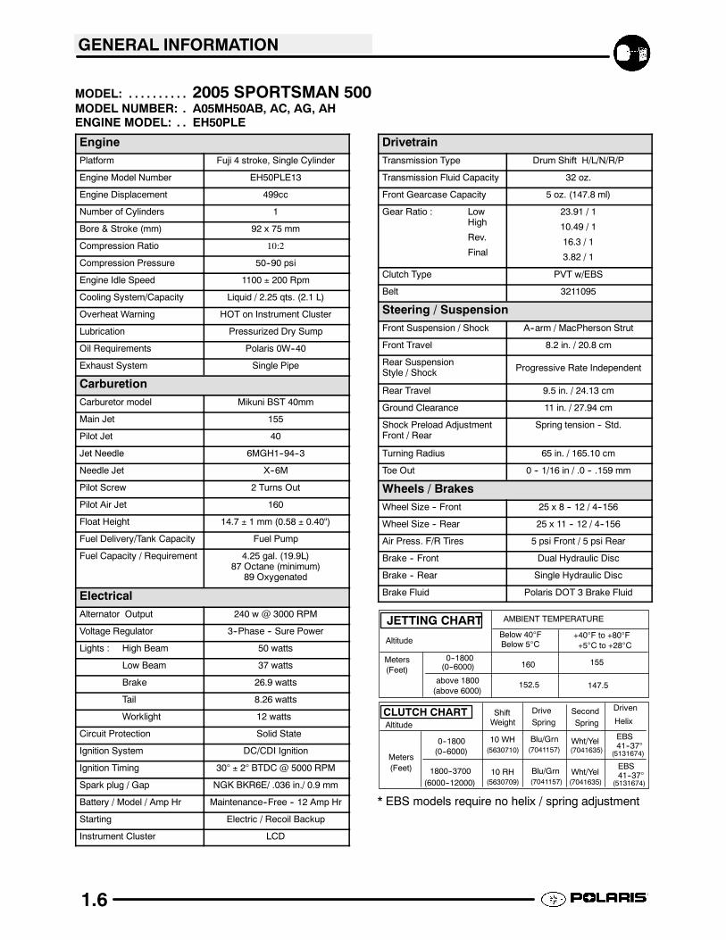
MODEL: 2005 SPORTSMAN 500. . . . . . . . . .MODEL NUMBER: A05MH50AB, AC, AG, AH.ENGINE MODEL: EH50PLE. .
EnginePlatform Fuji 4 stroke, Single Cylinder
Engine Model Number EH50PLE13
Engine Displacement 499cc
Number of Cylinders 1
Bore & Stroke (mm) 92 x 75 mm
Compression Ratio 10:2
Compression Pressure 50--90 psi
Engine Idle Speed 1100 ± 200 Rpm
Cooling System/Capacity Liquid / 2.25 qts. (2.1 L)
Overheat Warning HOT on Instrument Cluster
Lubrication Pressurized Dry Sump
Oil Requirements Polaris 0W--40
Exhaust System Single Pipe
CarburetionCarburetor model Mikuni BST 40mm
Main Jet 155
Pilot Jet 40
Jet Needle 6MGH1--94--3
Needle Jet X--6M
Pilot Screw 2 Turns Out
Pilot Air Jet 160
Float Height 14.7 ± 1 mm (0.58 ± 0.40“)
Fuel Delivery/Tank Capacity Fuel Pump
Fuel Capacity / Requirement 4.25 gal. (19.9L)87 Octane (minimum)
89 Oxygenated
ElectricalAlternator Output 240 w @ 3000 RPM
Voltage Regulator 3--Phase -- Sure Power
Lights : High Beam 50 watts
Low Beam 37 watts
Brake 26.9 watts
Tail 8.26 watts
Worklight 12 watts
Circuit Protection Solid State
Ignition System DC/CDI Ignition
Ignition Timing 30° ± 2° BTDC @ 5000 RPM
Spark plug / Gap NGK BKR6E/ .036 in./ 0.9 mm
Battery / Model / Amp Hr Maintenance--Free -- 12 Amp Hr
Starting Electric / Recoil Backup
Instrument Cluster LCD
DrivetrainTransmission Type Drum Shift H/L/N/R/P
Transmission Fluid Capacity 32 oz.
Front Gearcase Capacity 5 oz. (147.8 ml)
Gear Ratio : LowHigh
Rev.
Final
23.91 / 1
10.49 / 1
16.3 / 1
3.82 / 1
Clutch Type PVT w/EBS
Belt 3211095
Steering / SuspensionFront Suspension / Shock A--arm / MacPherson Strut
Front Travel 8.2 in. / 20.8 cm
Rear SuspensionStyle / Shock Progressive Rate Independent
Rear Travel 9.5 in. / 24.13 cm
Ground Clearance 11 in. / 27.94 cm
Shock Preload AdjustmentFront / Rear
Spring tension -- Std.
Turning Radius 65 in. / 165.10 cm
Toe Out 0 -- 1/16 in / .0 -- .159 mm
Wheels / BrakesWheel Size -- Front 25 x 8 -- 12 / 4--156
Wheel Size -- Rear 25 x 11 -- 12 / 4--156
Air Press. F/R Tires 5 psi Front / 5 psi Rear
Brake -- Front Dual Hydraulic Disc
Brake -- Rear Single Hydraulic Disc
Brake Fluid Polaris DOT 3 Brake Fluid
JETTING CHART
Altitude
Meters(Feet)
AMBIENT TEMPERATURE
0--1800(0--6000)
above 1800(above 6000)
Below 40°FBelow 5°C
+40°F to +80°F+5°C to +28°C
160 155
152.5 147.5
CLUTCH CHARTAltitude
Meters(Feet)
0--1800(0--6000)
1800--3700(6000--12000)
Shift DriveSpring
Driven
HelixWeight
10 WH
10 RH
EBS41--37°
SecondSpring
Wht/Yel(5630710)
(5630709)
(7041635) (5131674)
(7041635)(7041157)
(7041157)
Wht/Yel(5131674)
Blu/Grn
Blu/Grn
EBS41--37°
* EBS models require no helix / spring adjustment

GENERAL INFORMATION
1.7
SPECIAL TOOLSPART NUMBER TOOL DESCRIPTION CHAPTER TOOL USED IN
PA--44689 Valve Clutch Adjuster 2
2872105 Water Pump Mechanical Seal Puller 2
8712100 or 8712500 Tachometer 2,10
2200634 Valve Seat Reconditioning Kit 3
2870390 Piston Support Block 3
2871043 Flywheel Puller 3
2871283 Crankshaft/Water Pump Seal Install Kit 3
5131135 Water Pump Install Kit 3
2870569 Crankshaft Truing Stand 5
2872314 Carburetor Float Adjustment Tool 4
2870975 Mity Vact Pressure Test Tool 3, 4, 9
2870871 Ball Joint Replacement Tool 5
2870872 Shock Spanner Wrench 2, 5
2870623 Shock Absorber Spring Compression Tool 5
2871572 Strut Rod Wrench 5
2871573 LH Strut Spring Compressor 5
2871574 RH Strut Spring Compressor 5
7052069 Charging Needle 5
2200421 Gas Shock Recharging Kit 5
2871352 Shock Rod Holding Tool 5
2871351 Foxt Shock IFP Depth Tool 5
2870506 Clutch Puller 6
9314177 Clutch Holding Wrench 6
2871358 Clutch Holding Fixture 6
2870341 Drive Clutch Spider Removal and Install Tool 6
2870654 Clutch Offset Alignment Tool 6
2870913 Driven Clutch Puller 6
2870910 Roller Pin Tool 6
2871226 Clutch Bushing Replacement Tool Kit 6
2870386 Piston Pin Puller 6
2872292 EBS Clutch Alignment Tool 6
2201379 EBS Bushing Replacement Kit 6
8700220 Clutch Compression Tool 6
2871025 Clutch Bushing Replacement Tool Kit 6
2871199 Seal Sleeve Installation Tool Kit 5, 7
2870888 Hilliard Clutch Garter Spring Installation Tool 7
2872608 Roller Pin Removal Tool 7
8700226 CV Boot Clamp Pliers 7
2871701 (Part of 2871702 Kit) 2 1/8 inch Wrench 8
2871697 (Part of 2871702 Kit) Center Drive Bushing Tool 8
2871695 (Part of 2871702 Kit) Backlash Setting Tool 8
2871698 (Part of 2871702 Kit) Rear Output Seal Driver 8
2871699 (Part of 2871702 Kit) Rear Driveshaft Seal Guide 8
2871282 Bearing Seal Driver (50 mm) 8
PV--43568 Fluket77 Digital Multimeter 10
2870630 Timing Light 10
2870836 Battery Hydrometer 10

GENERAL INFORMATION
1.8
SPECIAL TOOLS, CONT’D2460761 Hall Sensor Probe Harness 10
2871745 Static Timing Light Harness 10
NOTE: Polaris dealers can order the tools listed above through their Polaris Special Service Tools catalog.
SPECIAL TOOLSSpecial Tools maybe required while servicing yourmachine. Some of the tools listed are mandatory andother tools maybe substituted with a similar tool, ifavailable. Polaris reccommends the use of Polarisspecial tools when servicing any Polaris product.
Standard Tools and Engine Tools
PU--45432 -- Caliper orA Basic Caliper
Basic Micrometer
2871043 -- Flywheel Puller
2870773 -- C--Clip Install Tool
2870967 -- Slotted Nut Socket
8700229 -- Flywheel Holder & Adapter
Standard Tools and Engine Tools
2870569 -- Crankshaft True Kit
2870386 -- Piston Pin Puller
2871445 -- Piston Pin Puller Adapter
2870968 -- Counter Balance Puller
PA--44689 -- Valve/Clutch Adjuster
2870390 -- Piston Support Block
PV--43527 Oil Filter Wrench

GENERAL INFORMATION
1.9
Standard Tools and Engine Tools
2870303 -- Hone Kit
2870305 -- Stone Replacement Kit
2870459 -- Dial Indicator
2870588 -- Hone Oil (12 oz.)
2872105 -- Water Pump Seal Puller
PV--35667--A -- Cylinder Leakdown Tester
2200634 -- Valve SeatReconditioning Kit
Clutch (PVT) Tools
2870506 -- Drive Clutch Puller
2870913 -- Driven Clutch Puller
2870654 -- ATV Clutch Align Tool
2872292 -- EBS Clutch Align Tool
9914177--A -- Drive Clutch Holding Tool
8700220 -- Clutch Compression Tool
2871283 -- Crank/Water Pump SealInstall Kit

GENERAL INFORMATION
1.10
Clutch (PVT) Tools
2870341 -- Drive Clutch SpiderRemoval Tool
2870910 -- Roll Pin Tool
2871226 -- Clutch BushingReplacement Kit
2201379 -- EBS BushingReplacement Kit
2870338 -- Spider Nut Socket
2871358 -- Clutch Holding Fixture
2871025 -- Clutch Bushing ReplaceTool Kit
Suspension Tools
2870871 -- ATV Ball Joint Tool Kit
2871071 -- Shock Body Holding Tool
2870623 -- Shock Spring Compressor
2871572 -- Strut Rod Wrench
2871573 & 2871574 -- StrutSpring Compressor
8700225 & 8700226 -- CV BootClamp Pliers

GENERAL INFORMATION
1.11
Suspension Tools
2870872 -- Shock Spanner Wrench
2872608 -- Roll Pin Removal Tool
Transmission Tools
2871702 -- Shaft Drive Transmission& Front Gearcase Tool Kit
2871351 -- Shock IFP Depth Tool
2871282 -- Bearing/Seal Driver(50 mm)
Electrical Tools
PV--43568 --Fluke 77 Multimeter
2870836 -- Battery Hydrometer
8712500 --Tachometer
RPM
PV--39951--A --Tachometer
PV--39617 -- Current Clamp
Fuel & Brake Systems
2870975 -- Mity Vac

GENERAL INFORMATION
1.12
Electrical Tools
2870630 -- Timing Light
2871745 --Static Timing Light Harness
2460761 -- Hall Sensor Probe Harness
PV--39991 -- Peak Reading Adapter
PV--37453 -- Christie Se--SulfatingMulti--Battery Charger
PV--63070 -- Christie Multi--BatteryCharger
GENERAL INFORMATION
1.13
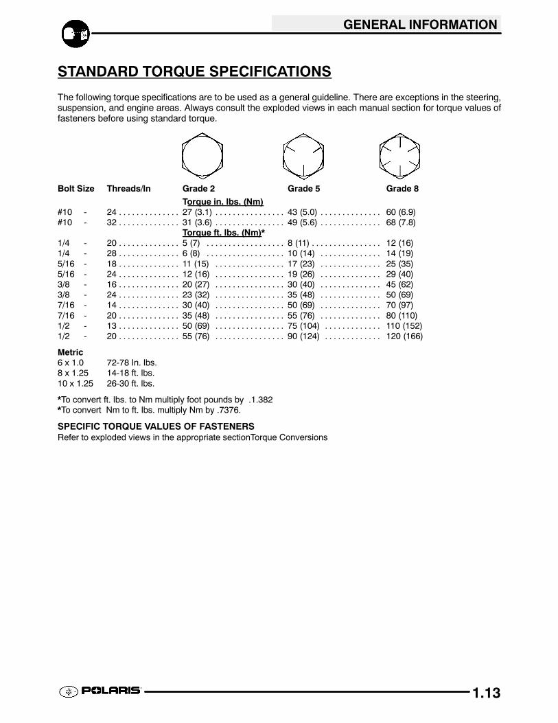
STANDARD TORQUE SPECIFICATIONS
The following torque specifications are to be used as a general guideline. There are exceptions in the steering,suspension, and engine areas. Always consult the exploded views in each manual section for torque values offasteners before using standard torque.
Bolt Size Threads/In Grade 2 Grade 5 Grade 8
Torque in. lbs. (Nm)#10 - 24 27 (3.1) 43 (5.0) 60 (6.9). . . . . . . . . . . . . . . . . . . . . . . . . . . . . . . . . . . . . . . . . . . .#10 - 32 31 (3.6) 49 (5.6) 68 (7.8). . . . . . . . . . . . . . . . . . . . . . . . . . . . . . . . . . . . . . . . . . . .
Torque ft. lbs. (Nm)*1/4 - 20 5 (7) 8 (11) 12 (16). . . . . . . . . . . . . . . . . . . . . . . . . . . . . . . . . . . . . . . . . . . . . . . .1/4 - 28 6 (8) 10 (14) 14 (19). . . . . . . . . . . . . . . . . . . . . . . . . . . . . . . . . . . . . . . . . . . . . .5/16 - 18 11 (15) 17 (23) 25 (35). . . . . . . . . . . . . . . . . . . . . . . . . . . . . . . . . . . . . . . . . . . .5/16 - 24 12 (16) 19 (26) 29 (40). . . . . . . . . . . . . . . . . . . . . . . . . . . . . . . . . . . . . . . . . . . .3/8 - 16 20 (27) 30 (40) 45 (62). . . . . . . . . . . . . . . . . . . . . . . . . . . . . . . . . . . . . . . . . . . .3/8 - 24 23 (32) 35 (48) 50 (69). . . . . . . . . . . . . . . . . . . . . . . . . . . . . . . . . . . . . . . . . . . .7/16 - 14 30 (40) 50 (69) 70 (97). . . . . . . . . . . . . . . . . . . . . . . . . . . . . . . . . . . . . . . . . . . .7/16 - 20 35 (48) 55 (76) 80 (110). . . . . . . . . . . . . . . . . . . . . . . . . . . . . . . . . . . . . . . . . . . .1/2 - 13 50 (69) 75 (104) 110 (152). . . . . . . . . . . . . . . . . . . . . . . . . . . . . . . . . . . . . . . . . . .1/2 - 20 55 (76) 90 (124) 120 (166). . . . . . . . . . . . . . . . . . . . . . . . . . . . . . . . . . . . . . . . . . .
Metric6 x 1.0 72-78 In. lbs.8 x 1.25 14-18 ft. lbs.10 x 1.25 26-30 ft. lbs.
*To convert ft. lbs. to Nm multiply foot pounds by .1.382*To convert Nm to ft. lbs. multiply Nm by .7376.
SPECIFIC TORQUE VALUES OF FASTENERSRefer to exploded views in the appropriate sectionTorque Conversions
GENERAL INFORMATION
1.14
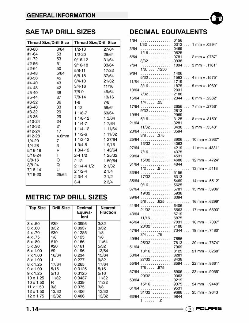
SAE TAP DRILL SIZES
Thread Size/Drill Size Thread Size/Drill Size
#0-80 3/64#1-64 53#1-72 53#2-56 51#2-64 50#3-48 5/64#3-56 45#4-40 43#4-48 42#5-40 38#5-44 37#6-32 36#6-40 33#8-32 29#8-36 29#10-24 24#10-32 21#12-24 17#12-28 4.6mm1/4-20 71/4-28 35/16-18 F5/16-24 I3/8-16 O3/8-24 Q7/16-14 U7/16-20 25/64
1/2-13 27/641/2-20 29/649/16-12 31/649/16-18 33/645/8-11 17/325/8-18 37/643/4-10 21/323/4-16 11/167/8-9 49/647/8-14 13/161-8 7/81-12 59/641 1/8-7 63/641 1/8-12 1 3/641 1/4-7 1 7/641 1/4-12 1 11/641 1/2-6 1 11/321 1/2-12 1 27/641 3/4-5 1 9/161 3/4-12 1 43/642-4 1/2 1 25/322-12 1 59/642 1/4-4 1/2 2 1/322 1/2-4 2 1/42 3/4-4 2 1/23-4 2 3/4
METRIC TAP DRILL SIZES
Tap Size Drill Size DecimalEquiva-
lent
NearestFraction
3 x .503 x .604 x .704 x .755 x .805 x .906 x 1.007 x 1.008 x 1.008 x 1.259 x 1.009 x 1.2510 x 1.2510 x 1.5011 x 1.5012 x 1.5012 x 1.75
#393/32#301/8#19#20#916/64J17/645/165/1611/32R3/813/3213/32
0.09950.09370.12850.1250.1660.1610.1960.2340.2770.2650.31250.31250.34370.3390.3750.4060.406
3/323/321/81/811/645/3213/6415/649/3217/645/165/1611/3211/323/813/3213/32
DECIMAL EQUIVALENTS1/64 .0156. . . . . . . . . . . . . . . .
1/32 .0312 1 mm = .0394″. . . . . . . . . . . . . .3/64 .0469. . . . . . . . . . . . . . . .
1/16 .0625. . . . . . . . . . .5/64 .0781 2 mm = .0787″. . . . . . . . . . . . . . . . . . .
3/32 .0938. . . . . . . . . . .7/64 .1094 3 mm = .1181″. . . . . . . . . . . . . . . . .
1/8. .1250. . .9/64 .1406. . . . . . . . . . . . . . . .
5/32 .1563 4 mm = .1575″. . . . . . . . . . . . . .11/64 .1719. . . . . . . . . . . . . . .
3/16 .1875 5 mm = .1969″. . . . . . . . . . . . . .13/64 .2031. . . . . . . . . . . . . . .
7/32 .2188. . . . . . . . . . .15/64 .2344 6 mm = .2362″. . . . . . . . . . . . . . . . . .
1/4 .25. . . .17/64 .2656 7 mm = .2756″. . . . . . . . . . . . . . . . . .
9/32 .2813. . . . . . . . . . .19/64 .2969. . . . . . . . . . . . . . .
5/16 .3125 8 mm = .3150″. . . . . . . . . . . . . .21/64 .3281. . . . . . . . . . . . . . .
11/32 .3438 9 mm = .3543″. . . . . . . . . . . . .23/64 .3594. . . . . . . . . . . . . . .
3/8 .375. . . .25/64 .3906 10 mm = .3937″. . . . . . . . . . . . . . . . . .
13/32 .4063. . . . . . . . .27/64 .4219 11 mm = .4331″. . . . . . . . . . . . . . . . . .
7/16 .4375. . . . . . . . . . .29/64 .4531. . . . . . . . . . . . . . .
15/32 .4688 12 mm = .4724″. . . . . . . . . . . .31/64 .4844. . . . . . . . . . . . . . .
1/2 .5 13 mm = .5118. . . . . . . . . . . . . . . . . .33/64 .5156. . . . . . . . . . . . . . .
17/32 .5313. . . . . . . . .35/64 .5469 14 mm = .5512″. . . . . . . . . . . . . . . . . .
9/16 .5625. . . . . . . . . . .37/64 .5781 15 mm = .5906″. . . . . . . . . . . . . . . . . .
19/32 .5938. . . . . . . . .39/64 .6094. . . . . . . . . . . . . . .
5/8 .625 16 mm = .6299″. . . . . . . . . . . . . . . .41/64 .6406. . . . . . . . . . . . . . .
21/32 .6563 17 mm = .6693″. . . . . . . . . . . .43/64 .6719. . . . . . . . . . . . . .
11/16 .6875. . . . . . . . . .45/64 .7031 18 mm = .7087″. . . . . . . . . . . . . . . . . .
23/32 .7188. . . . . . . . .47/64 .7344 19 mm = .7480″. . . . . . . . . . . . . . . . . .
3/4 .75. . . .49/64 .7656. . . . . . . . . . . . . . .
25/32 .7813 20 mm = .7874″. . . . . . . . . . . .51/64 .7969. . . . . . . . . . . . . . .
13/16 .8125 21 mm = .8268″. . . . . . . . . . . .53/64 .8281. . . . . . . . . . . . . . .
27/32 .8438. . . . . . . . .55/64 .8594 22 mm = .8661″. . . . . . . . . . . . . . . . . .
7/8 .875. . . .57/64 .8906 23 mm = .9055″. . . . . . . . . . . . . . . . . .
29/32 .9063. . . . . . . . .59/64 .9219. . . . . . . . . . . . . .
15/16 .9375 24 mm = .9449″. . . . . . . . . . . .61/64 .9531. . . . . . . . . . . . . . .
31/32 .9688 25 mm = .9843. . . . . . . . . . . .63/64 .9844. . . . . . . . . . . . . . .
1 1.0. . . . .
GENERAL INFORMATION
1.15
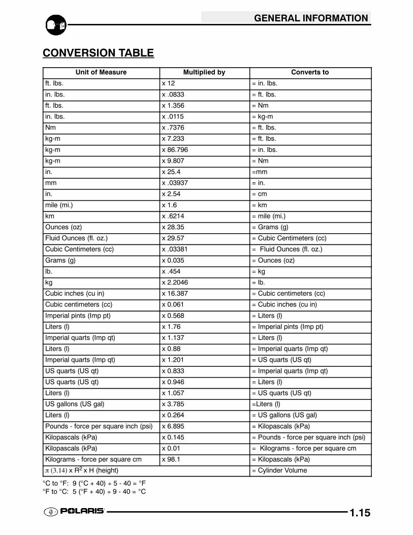
CONVERSION TABLE
Unit of Measure Multiplied by Converts to
ft. lbs. x 12 = in. lbs.
in. lbs. x .0833 = ft. lbs.
ft. lbs. x 1.356 = Nm
in. lbs. x .0115 = kg-m
Nm x .7376 = ft. lbs.
kg-m x 7.233 = ft. lbs.
kg-m x 86.796 = in. lbs.
kg-m x 9.807 = Nm
in. x 25.4 =mm
mm x .03937 = in.
in. x 2.54 = cm
mile (mi.) x 1.6 = km
km x .6214 = mile (mi.)
Ounces (oz) x 28.35 = Grams (g)
Fluid Ounces (fl. oz.) x 29.57 = Cubic Centimeters (cc)
Cubic Centimeters (cc) x .03381 = Fluid Ounces (fl. oz.)
Grams (g) x 0.035 = Ounces (oz)
lb. x .454 = kg
kg x 2.2046 = lb.
Cubic inches (cu in) x 16.387 = Cubic centimeters (cc)
Cubic centimeters (cc) x 0.061 = Cubic inches (cu in)
Imperial pints (Imp pt) x 0.568 = Liters (l)
Liters (l) x 1.76 = Imperial pints (Imp pt)
Imperial quarts (Imp qt) x 1.137 = Liters (l)
Liters (l) x 0.88 = Imperial quarts (Imp qt)
Imperial quarts (Imp qt) x 1.201 = US quarts (US qt)
US quarts (US qt) x 0.833 = Imperial quarts (Imp qt)
US quarts (US qt) x 0.946 = Liters (l)
Liters (l) x 1.057 = US quarts (US qt)
US gallons (US gal) x 3.785 =Liters (l)
Liters (l) x 0.264 = US gallons (US gal)
Pounds - force per square inch (psi) x 6.895 = Kilopascals (kPa)
Kilopascals (kPa) x 0.145 = Pounds - force per square inch (psi)
Kilopascals (kPa) x 0.01 = Kilograms - force per square cm
Kilograms - force per square cm x 98.1 = Kilopascals (kPa)
π (3.14) x R2 x H (height) = Cylinder Volume
°C to °F: 9 (°C + 40) ÷ 5 - 40 = °F°F to °C: 5 (°F + 40) ÷ 9 - 40 = °C

GENERAL INFORMATION
1.16
GLOSSARY OF TERMSABDC: After bottom dead center.ACV: Alternating current voltage.Alternator: Electrical generator producing voltage alternating current.ATDC: After top dead center.BBDC: Before bottom dead center.BDC: Bottom dead center.BTDC: Before top dead center.CC: Cubic centimeters.Center Distance: Distance between center of crankshaft and center of driven clutch shaft.Chain Pitch: Distance between chain link pins (No. 35 = 3/8″ or 1 cm). Polaris measures chain length in number of pitches.CI: Cubic inches.Clutch Buttons: Plastic bushings which aid rotation of the movable sheave in the drive and driven clutch.ClutchOffset: Drive and driven clutches are offset so that drive belt will stay nearly straight as it moves along the clutch face.Clutch Weights: Three levers in the drive clutch which relative to their weight, profile and engine RPM cause the driveclutch to close and grip the drive belt.Crankshaft Run-Out: Run-out or “bend” of crankshaft measured with a dial indicator while crankshaft is supportedbetween centers on V blocks or resting in crankcase. Measure at various points especially at PTO.DCV: Direct current voltage.Dial Bore Gauge: A cylinder measuring instrument which uses a dial indicator. Good for showing taper andout-of-round in the cylinder bore.Electrical Open: Open circuit. An electrical circuit which isn’t complete.Electrical Short: Short circuit. An electrical circuit which is completed before the current reaches the intended load.(i.e. a bare wire touching the chassis).End Seals: Rubber seals at each end of the crankshaft.Engagement RPM: Engine RPM at which the drive clutch engages to make contact with the drive belt.ft.: Foot/feet.Foot Pound: Ft. lb. A force of one pound at the end of a lever one foot in length, applied in a rotational direction.g: Gram. Unit of weight in the metric system.gal.: Gallon.ID: Inside diameter.in.: Inch/inches.Inch Pound: In. lb. 12 in. lbs. = 1 ft. lb.
kg/cm2
: Kilograms per square centimeter.kg-m: Kilogram meters.Kilogram/meter: A force of one kilogram at the end of a lever one meter in length, applied in a rotational direction.l or ltr: Liter.
lbs/in2
: Pounds per square inch.Left or Right Side: Always referred to based on normal operating position of the driver.m: Meter/meters.Mag: Magneto.Magnetic Induction: As a conductor (coil) is moved through a magnetic field, a voltage will be generated in thewindings. Mechanical energy is converted to electrical energy in the stator.mi.: Mile/miles.mm: Millimeter. Unit of length in the metric system. 1mm = approximately .040″.Nm: Newton meters.OD: Outside diameter.Ohm: The unit of electrical resistance opposing current flow.oz.: Ounce/ounces.Piston Clearance: Total distance between piston and cylinder wall.psi.: Pounds per square inch.PTO: Power take off.PVT: Polaris Variable Transmission (Drive Clutch System)qt.: Quart/quarts.Regulator: Voltage regulator. Regulates battery charging system output at approx. 14.5 DCV as engine RPM increases.Reservoir Tank: The fill tank in the liquid cooling system.Resistance: In the mechanical sense, friction or load. In the electrical sense, ohms, resulting in energy conversion to heat.RPM: Revolutions per minute.Seized Piston: Galling of the sides of a piston. Usually there is a transfer of aluminum from the piston onto the cylinder wall.Possible causes: 1) improper lubrication; 2) excessive temperatures; 3) insufficient piston clearance; 4) stuck piston rings.Stator Plate: The plate mounted under the flywheel supporting the battery charging coils.TDC: Top dead center. Piston’s most outward travel from crankshaft.Volt: The unit of measure for electrical pressure of electromotive force. Measured by a voltmeter in parallel with the circuit.Watt: Unit of electrical power. Watts = amperes x volts.WOT: Wide open throttle.

MAINTENANCE
2.1
Periodic Maintenance Chart 2.2-2.5. . . . . . . . . . . . . . .
Lubricant and Maintenance Product Numbers 2.6--2.7
ATV Component Locations 2.8. . . . . . . . . . . . . . . .
Lubrication Charts 2.9. . . . . . . . . . . . . . . . . . . . . . . .Front Gearcase Lubrication 2.10-2.11. . . . . . . . . . . . . . . .
Transmission Lubrication 2.11-2.12. . . . . . . . . . . . . . . . . .
Lubrications Points 2.12--2.13. . . . . . . . . . . . . . . . . . . . . . .
Transmission Linkage Adjustment 2.13. . . . . . . . . .
Carburetor / Throttle Adjustments 2.13-2.16. . . . . . . . . .
Fuel System 2.16-2.17. . . . . . . . . . . . . . . . . . . . . . . . . . . . .Compression Test 2.18. . . . . . . . . . . . . . . . . . . . . . . .
Battery Maintenance 2.19. . . . . . . . . . . . . . . . . . . . . .
Coolant System Maintenance 2.19-2.21. . . . . . . . . . . . . .
Air Filter Service 2.21-2.22. . . . . . . . . . . . . . . . . . . . . . . . .
Air Box Sediment Tube Service 2.22. . . . . . . . . . . .Breather Filter 2.23. . . . . . . . . . . . . . . . . . . . . . . . . . .
Recoil Housing 2.23. . . . . . . . . . . . . . . . . . . . . . . . . . .
Oil Change/Filter 2.24-2.26. . . . . . . . . . . . . . . . . . . . . . . . .
Valve Clearance 2.26-2.27. . . . . . . . . . . . . . . . . . . . . . . . .
Steering and Toe Alignment 2.27-2.30. . . . . . . . . . . . . . .Exhaust System Maintenance 2.31. . . . . . . . . . . . .
Brake System Service 2.31-2.32. . . . . . . . . . . . . . . . . . . .
Suspension Service 2.33. . . . . . . . . . . . . . . . . . . . . .
Controls 2.33. . . . . . . . . . . . . . . . . . . . . . . . . . . . . . . . .
Wheel Removal/Installation 2.34. . . . . . . . . . . . . . . .
Tire Inspection 2.34. . . . . . . . . . . . . . . . . . . . . . . . . . .Compartment Storage 2.35. . . . . . . . . . . . . . . . . . . .
Warnt Winch Operation 2.36--2.37. . . . . . . . . . . . . . . . . .
Cleaning and Storage of ATV 2.38--2.39. . . . . . . . . . . . . .

MAINTENANCE
2.2
PERIODIC MAINTENANCE CHARTCareful periodic maintenance will help keep your vehicle in the safest, most reliable condition. Inspection,adjustment and lubrication of important components are explained in the periodic maintenance chart.
Inspect, clean, lubricate, adjust and replace parts as necessary. When inspection reveals the need forreplacement parts, use genuine Polaris parts available from your Polaris dealer.
NOTE: Service and adjustments are critical. If you’re not familiar with safe service and adjustmentprocedures, have a qualified dealer perform these operations.
Maintenance intervals in the following chart are based upon average riding conditions and an average vehiclespeed of approximately 10 miles per hour. Vehicles subjected to severe use must be inspected and serviced morefrequently.
Severe Use Definition
S Frequent immersion in mud, water or sandS Racing or race-style high RPM useS Prolonged low speed, heavy load operation
S Extended idleS Short trip cold weather operation
Pay special attention to the oil level. A rise in oil level during cold weather can indicate contaminants collectingin the oil sump or crankcase. Change oil immediately if the oil level begins to rise. Monitor the oil level, and ifit continues to rise, discontinue use and determine the cause or see your dealer.
Maintenance Chart KeyThe following symbols denote potential items to be aware of during maintenance:
H= CAUTION: Due to the nature of these adjustments, it is recommended this service be performedby an authorized Polaris dealer.
"= SEVERE USE ITEM ----If vehicle is subjected to severe use, decrease interval by 50%(Severe Use is defined as frequent vehicle immersion in mud, water or sand, racing or race-style high rpmuse, prolonged low speed - heavy load operation or extended idle. More preventative maintenance isrequired under these conditions. Fluid changes, cable, chain and chassis lubrication are required morefrequently. For engine oil, short trip cold weather riding also constitutes severe use. Pay special attentionto oil level. A rising oil level in cold weather can indicate contaminants collecting in the oil sump orcrankcase. Change oil immediately and monitor level. If oil level begins to rise, discontinue use anddetermine cause.)E= Emission Control System Service (California).NOTE: Inspection may reveal the need for replacement parts. Always use genuine Polaris parts.
WARNING: Improperly performing the procedures marked with a J could result in component failure and leadto serious injury or death. Have an authorized Polaris dealer perform these services.