sporting clays instruction manual - native outdoors · features and benefits of the easy bird...
TRANSCRIPT
EASYBIRD AUTO-FEED
DOUBLES 12VDC Part No. 45322
Instruction ManualT
WARNING: THIS MACHINE CAN CAUSE SERIOUS INJURY OR DEATH!
HOROUGHLY READ INSTRUCTIONS BEFORE INSTALLING OR OPERATING TRAP!

Table of Contents
Section Page I. Introduction ....................................................................................... 1
II. Safety ............................................................................................... 2
III. Assembly and Installation ................................................................ 5 1. Contents of Package ...................................................................................5 2. Unpacking....................................................................................................6 3. Mounting the Trap .......................................................................................6 4. Mounting the Magazine Assemblies............................................................8 5. Mounting the Throwing Arm Path Indicator .................................................8 6. Installing the Mainspring..............................................................................9 7. Power supply and release cord installation .................................................10
IV. Operation .......................................................................................... 11
V. Adjustments ...................................................................................... 13 1. Throwing arm limit switch ...........................................................................13 2. Elevation Adjustment...................................................................................14 3. Distance Adjustment....................................................................................15 4. ATA Doubles Setting ................................................................... 16
VI. Troubleshooting ................................................................................ 17
VII. Maintenance ..................................................................................... 18
VIII. Replacement Parts.............................................................................................18 IX. Warranty Information ........................................................................................19 X. Contact Information............................................................................................20

1
I. Introduction The EasyBird Auto-Feed Doubles Trap is designed for the active sporting clays, trap, and skeet shooter looking for an automatic, lightweight, and portable machine for practice shooting. Features and benefits of the Easy Bird Auto-Feed Doubles Trap: Safety
On-Off-Safe Release switch provides safe method to uncock arm. Arm safety ring provides visual indication of throwing arm path for safety. 30 amp circuit breaker protects electrical wires and motor.
Convenience
Lightweight and portable - approximately 50 lbs. Detachable magazines each hold 50 targets. Throws standard 108 mm or 110mm international clay targets. 50 ft. release cord with foot pedal release. Easily mounts to Champion Trap Taxi 40261 (sold separately). Three legged adjustable stand provides stable launch platform.
Performance
Fast, 1-second cycle time. Adjustable throwing range from 35 to 50 yards. Can be used exclusively for singles or doubles presentations. Adjustable to throw an ATA doubles presentation. Runs off 12 volt battery (deep cycle type recommended). Balanced throwing arms with replaceable flight rails. Will throw 3000 – 5000 targets with a fully charged battery. No throwing plate to adjust. Targets delivered directly to throwing arms.
II. Safety
WARNING: THIS MACHINE CAN CAUSE SERIOUS INJURY OR DEATH!!!! READ THOROUGHLY INSTRUCTIONS AND WARNINGS BEFORE INSTALLING OR OPERATING TRAP!
DO NOT STAND IN FRONT OF THE TRAP WHEN IT IS IN THE COCKED POSITION. SERIOUS INJURY OR DEATH CAN RESULT.
THIS TRAP IS CAPABLE OF THROWING TARGETS OVER 50 YARDS. USE ONLY IN AREAS WHERE THERE IS NO RISK OF CAUSING DAMAGE OR HITTING A PERSON WITH A TARGET.
Caution: The Easybird Auto-Feed Doubles Trap must have ample clearance around the trap. The on/off/safe release switch for the trap is located on the rear of the trap and allows the trap to be uncocked before approaching it.
WARNING: IF THERE ARE TARGETS ON THE THROWING ARMS, SAFE RELEASING THE TRAP WILL THROW THE TARGETS. DO NOT STAND IN FRONT OF THE TRAP WHILE SAFE RELEASING.
DO NOT INSTALL THE TRAP IN AN AREA THAT DOES NOT ALLOW SAFE (REAR) ACCESS TO THE TRAP AND THE ON/OFF/SAFE RELEASE SWITCH DURING LOADING AND USE.
2

WARNING: BEFORE PERFORMING ANY REPAIR, MAINTENANCE, OR ASSEMBLY, MAKE SURE THE THROWING ARMS ARE IN THE UNCOCKED POSITION (SEE PHOTO BELOW), THE ON/OFF/SAFE RELEASE SWITCH LOCATED ON THE REAR OF THE TRAP IS IN THE ‘OFF‘ POSITION (SEE PHOTO BELOW) , AND THE BATTERY IS DISCONNECTED FROM THE TRAP.
1. If the throwing arms are in the cocked arm position (see photo below), Uncock the throwing arms by first connecting the red battery lead to the positive (+) terminal and the black battery lead to the negative (-) terminal on the battery. Momentarily press the on/off/safe release switch to the “SAFE RELEASE” position to fire the trap. After the trap fires, release the on/off/safe release switch allowing it to return to the “OFF” position. The throwing arms should now be in the uncocked position. Disconnect the battery from the trap.
Throwing Arm Flight Rail
Cocked Arm Position Uncocked “Safe Release” Arm Position
On/Off/Safe Release Switch
Circuit Breaker
3

All personnel operating the trap should be thoroughly familiar with the operating instructions and the safety issues relating to the trap. 2. Do not leave trap in the cocked position. Not only is this potentially dangerous,
but it puts undue stress on the mainspring. 3. Always load the trap magazine from the rear of the trap. 4. Keep hands and body outside the trap and throwing arm path indicator areas
while the trap is operating. This ring shows the throwing arm’s path when throwing a target, and should always be attached to the trap when it is in use.
5. Be aware that a cracked or broken target thrown from the trap will sometimes scatter pieces out the right side of the machine as the arms throw. These pieces may hit nearby unsuspecting bystanders.
6. Always wear eye and hearing protection when shooting.
WARNING: FAILURE TO FOLLOW SAFETY RULES CAN RESULT IN SERIOUS INJURY OR DEATH!
4

III. Assembly and Installation 1. Contents of Trap Box N - Contents of Stand Boxes
ITEM DESCRIPTION
A. EASYBIRD AUTO-FEED TRAP B. Instruction Manual C. Arm Path Indicator Tubing - 3 ea D. Magazine Rod – 8 ea. E. Front Tube Support - 2 ea. F. Mainspring G. Magazine Top Plate - 2 ea. H. Mainspring Bolt I. Mainspring Bushing J. Flat Washer K. Tension Adjustment Flange Nut L. Tension Adjustment Lock Nut M. Magazine Top Plate Screws – 8 N. Three Legged Stand Boxes
N2
N2 N1
N3
N4 N7 N6 N5N4
C – Arm Path Indicator TubingD - Magazine Rods
8 included
F - Mainspring
E – Front Tube Supports
G - Magazine Top Plates 2 included
H - Mainspring Bolt
I - Mainspring Bushing
L - Tension Adjustment Lock Nut
K - Tension Adjustment Flange Nut J - Flat Washer
M - Magazine Top Plate Screws 8 included5

2. Unpacking
1. Carefully inspect the carton and trap machine to be sure that damage hasn’t occurred during shipping. Report any damage found immediately to the shipper.
2. Check that all parts were included in shipping box. If any parts are missing, call the CHAMPION Customer Service Department at (800) 635-7656 to obtain replacement parts.
3. Carefully remove trap and all other components from cardboard shipping box. 4. Remove the carriage bolts, large washers, lock washers, and wing nuts that
secure the trap to the shipping board. Save these for mounting the trap if needed.
5. Save all packing material and box if trap should ever need to be returned for service or replacement.
6. Refer to the following installation instructions prior to assembling the trap.
3. Mounting the Trap
Caution: The Easybird Auto-Feed Trap must be bolted down to a flat, solid surface, the three legged stand, or the Trap Taxi trailer to minimize movement of the trap while operating. Failure to do so may damage the machine and void warranty.
Provide ample clearance around the trap.
The on/off/safe release switch for the trap is located on the rear of the trap and allows the trap to be uncocked before approaching it.
WARNING: IF THERE ARE TARGETS ON THE THROWING ARMS, SAFE RELEASING THE TRAP WILL THROW THE TARGETS. DO NOT STAND IN FRONT OF THE TRAP WHILE SAFE RELEASING THE TRAP. DO NOT INSTALL THE TRAP IN AN AREA THAT DOES NOT ALLOW SAFE (REAR) ACCESS TO THE TRAP AND THE ON/OFF/SAFE RELEASE SWITCH DURING LOADING AND USE. 1. The trap may be mounted to any suitable platform or surface, providing it is
sturdy and provides a means to bolt the trap down in at least two places. Carefully lift the trap and place it on the mounting surface. Install using bolts, washers, and nuts provided to securely fasten trap to mounting surface. Add additional bolts and nuts if necessary.
6

2. To assemble and mount the trap to the three-legged stand:
N7 N1
N3 N6N2
N2
Front of Machine
7
N4 N4Slide each front leg pad (N4) over front leg (N2) and
attach with (N5) 50mm long hex bolts, washers, and nuts. Slide each leg (N1 and N2) into frame plate (N3) as shown. Attach each leg to frame plate with (N6) 50mm long hex head bolts, washers, and lock nuts. Attach trap to frame plate with (N7) 20mm long hex head bolts, washers, and lock nuts. Tighten all nuts and bolts securely.
N5
5
For initial setup left front leg should be set longer as shown with bolt in 3rd hole of left front leg pad. If using the Trap Taxi or a mounting plate, block up the left wheel or side of the plate approximately 2 inches.
N

4. Mounting the Magazine Assemblies
The eight (8) Magazine Rods (D) are attached to the trap by slipping them over the studs mounted to the trap top plate. Attach each Magazine Top Plate (G) with four (4) Magazine Top Plate Screws (M) keeping the opening of the Magazine Top Plate toward the rear of the machine. Rear of
Machine
5. Mounting the Throwing Arm Path Indicator
Magazine Top Plate Magazine Rods
1. Attach the two (2) Front Tube Supports (E) to front sides of trap body using the four (4) bolts in the lower front body (two on each side). Make sure that warning labels are upright. Tighten all four (4) bolts on Front Tube Supports securely. 2. Slide three (3) pieces of Arm Path Indicator Tubing (C) over ends of Front Tube Supports and Rear Tube Support Studs at rear of trap body. This ring indicates the approximate path of the Throwing Arm.
WARNING: FAILURE TO KEEP HANDS AND BODY OUTSIDE THE THROWING ARM PATH INDICATOR AREA CAN RESULT IN SERIOUS INJURY OR DEATH FROM BEING STRUCK BY THE THROWING ARM DURING USE. Caution: Do not lift trap by throwing arm path indicator, or front tube supports, these were not designed to be a lifting point.
Arm Path Indicator Tubing
Rear Tube
Support Stud Front Tube Supports
8

6. Installing the Mainspring
1. Remove the plastic tie holding the arm in place and rotate the top arm counter clockwise 180° so it is facing forward of the trap in the 12 o’clock position. (If arm cannot be rotated to 180° position, connect the trap to a battery as shown in step 7 and briefly push and release the safe release switch, this will move the drive bar out of the way and allow the arm to be moved forward, REMOVE BATTERY CONNECTIONS after top arm is in 180° - 12 o’clock position)
2. Remove Mainspring (F) and all remaining hardware from shipping cartons and bags.
3. Mainspring Hex Bolt (H) should be assembled into Mainspring (F) through largest opening with the threaded end of mainspring bolt showing.
4. Attach the hook end of the mainspring through the crankshaft eyebolt located inside of trap body (eyebolt should be pointing toward rear of trap)
5. Push threaded end of Mainspring Bolt through hole in rear of body. 6. Slide Mainspring Bushing (I) over Mainspring Hex Bolt so small end fits into
trap body 7. Attach Flat Washer (J) and Tension Adjustment Flange Nut (K) 8. With the throwing arm still facing forward of the trap, tighten the Tension
Adjustment Flange Nut until all the slack is taken up in the spring and bolt. This is the minimum spring tension point and operating the trap at any less tension will cause “spring slap” that can damage the machine. Add the Tension Adjustment Lock Nut (L) and tighten against 1st nut.
9
Mainspring Bolt
9. The throwing arms are now in the uncocked position and is under minimum tension.
Rear of Trap
Flat Washer
Tension Adjustment Lock Nut
Tension Adjustment Flange Nut Mainspring
Bushing

7. Power Supply and Release Cord Installation
WARNING: MAKE SURE THAT THE “ON-OFF-SAFE RELEASE” SWITCH IS SET TO THE “OFF” POSITION BEFORE CONNECTING POWER TO THE TRAP.
1. Connect the red battery lead to the positive (+) terminal and the black battery
lead to the negative (-) terminal of an adequately charged deep cycle 12V battery.
Remote Release Cord
10

IV. Operation
WARNING: DO NOT STAND IN FRONT OF TRAP OR IN THE PATH OF THE THROWING ARM! SERIOUS INJURY OR DEATH MAY RESULT!
1. The throwing arm path indicator must be mounted properly before using trap. 2. Make sure that the trap is located to allow ample clearance around machine
and provides safe access to the rear of the trap during operation. The trap must be located so that the user has safe access to the rear to operate the On/Off/Safe Release switch and reload the trap.
3. Make sure that the On/Off/Safe Release switch is in the “OFF” position, and the arms are in the uncocked position (page 3)
4. To throw doubles presentation, load both magazines. To throw single targets, load left or right magazine only.
5. Place four (4) targets into each magazine and hold them flat. The targets should be resting on the slide plate.
Target Retainer Loading Bars
Slide Plate
6. If the trap has been safe released and the throwing arms are in the uncocked position it may be necessary to pull back on the Target Retainer Bar and then place the targets into each magazine and hold the targets flat.
11

Target Retainer
7. Release the Target Retainer Bar(s) if it was being held. The rubber target retainer should be pressing on the 2nd target. The notch in the target retainer is at the bottom to clear the first target. Continue to load targets into the magazine columns.
8. Make sure that there is an adequately charged 12VDC battery connected to the trap and that the remote release cord is safely away from and behind the trap.
9. Turn the On/Off/Safe Release switch to the “ON” position. 10. The trap should cock the throwing arms and at the same time drop the
targets onto the throwing arms as they are cocking. If the arms do not stop, or the targets don’t drop, the limit switch will need to be adjusted.
11. Activate the Remote Release “fire” button and the EasyBird Auto-Feed Doubles will release the throwing arms (launching the targets), re-cock the throwing arms and deliver targets to the throwing arms.
WARNING: IF THERE ARE TARGETS ON THE THROWING ARMS, SAFE RELEASING THE TRAP WILL THROW THE TARGETS. DO NOT STAND IN FRONT OF THE TRAP. 12. When reloading the trap, first move the ON/OFF/SAFE RELEASE switch on
the trap to the “Safe Release” position momentarily to uncock the throwing arm. Allow the switch to return to the ‘OFF’ position. The target magazines can then be safely reloaded with targets from the rear of the trap.
12

V. Adjustments1. Throwing Arm Limit Switch
WARNING: BEFORE MAKING ANY ADJUSTMENTS, MAKE SURE THE THROWING ARMS ARE IN THE UNCOCKED POSITION, THE ON/OFF/SAFE RELEASE SWITCH IS IN THE “OFF” POSITION, AND THE BATTERY IS DISCONNECTED FROM THE TRAP.
The machine is set at the factory. Only make adjustments to the limit switch if targets do not drop onto the throwing arms as the throwing arms are cocking, or the throwing arms continuously fire. TEST MACHINE FIRST WITHOUT ANY TARGETS.
13
1. The limit switch controls the stop position of the throwing arms during the traps cocking cycle. The limit switch is located under the trap near the front. Adjustments to the limit switch are made by loosening the two mounting screws and moving the switch slightly. Move the switch towards the center of the trap for the arm to stop further away from the edge of the main body. Move the switch towards the end of the trap for the arm to stop closer to the edge of the main body. Re-tighten the mounting screws after adjusting the switch.
Move switch this direction to stop arm closer to edge of top
plate
Slide plate lines up with
top plate
2. Adjust switch so that targets drop onto the throwing arms as the arms are cocking. The tip of the top arm should stop within 4.5” to 5.5” from the edge of the top plate of the trap. The openings in the sliding plate should line up with the openings in the top plate and allow targets to drop.
Move switch this direction to stop arm further from edge of
top plate 4.5” – 5.5“
Caution: Adjusting the arm to stop at a point too far away from the spring’s over-center point can result in a delayed release or improper loading and targets breaking.
WARNING: ADJUSTING THE ARM TO STOP AT A POINT TOO CLOSE TO THE SPRING’S OVER-CENTER POINT CAN RESULT IN THE ARM CONTINUOUSLY FIRING AND CAUSING POTENTIAL INJURY FROM BEING STRUCK BY THE ARM.

2. Elevation Adjustment
WARNING: BEFORE MAKING ANY ADJUSTMENTS, MAKE SURE THE THROWING ARMS ARE IN THE UNCOCKED POSITION, THE ON/OFF/SAFE RELEASE SWITCH IS IN THE “OFF” POSITION, AND THE BATTERY IS DISCONNECTED FROM THE TRAP. 1. To adjust the elevation, slightly loosen the four nuts--two on each side of the
trap. 2. Change the elevation by grasping the trap main body and pivoting the trap to
the desired position. 3. Re-tighten the four nuts to secure the trap in the new position.
Elevation Adjustment
14

3. Distance Adjustment
WARNING: BEFORE MAKING ANY ADJUSTMENTS, MAKE SURE THE THROWING ARMS ARE IN THE UNCOCKED POSITION, THE ON/OFF/SAFE RELEASE SWITCH IS IN THE “OFF” POSITION, AND THE BATTERY IS DISCONNECTED FROM THE TRAP. THIS TRAP IS CAPABLE OF THROWING TARGETS OVER 50 YARDS. USE ONLY IN AREAS WHERE THERE IS NO RISK OF CAUSING DAMAGE OR HITTING A PERSON WITH A TARGET. The trap has an adjustable throwing range of approximately 35 to 50 yards. Adjustments to throwing distance are made by adjusting the mainspring tension. 1. Loosen the Tension Adjustment Lock Nut. Turn the Tension Adjustment
Flange Nut clockwise to increase spring tension and target distance, or counter-clockwise to decrease spring tension and target distance.
2. Maximum spring tension is set when the Mainspring Bushing contacts the shoulder in the mainspring bolt and the Tension Adjustment Flange Nut cannot be turned any farther. DO NOT EXCEED THIS AMOUNT.
3. Make sure the spring tension is not reduced to the point that there is slack in the spring when the top arm is in the twelve o’clock position (straight out in front). Take up any slack in the spring when the arm is in this position. This is the minimum tension point to ensure that damaging spring slap does not occur.
4. After adjusting the spring to the desired tension, tighten the Tension Adjustment Lock Nut against the Tension Adjustment Flange Nut to lock the setting in place.
Mainspring Bushing
Tension Adjustment Flange Nut
Tension Adjustment Lock Nut
15
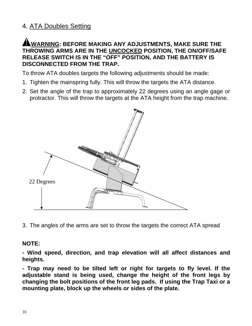
4. ATA Doubles Setting
WARNING: BEFORE MAKING ANY ADJUSTMENTS, MAKE SURE THE THROWING ARMS ARE IN THE UNCOCKED POSITION, THE ON/OFF/SAFE RELEASE SWITCH IS IN THE “OFF” POSITION, AND THE BATTERY IS DISCONNECTED FROM THE TRAP. To throw ATA doubles targets the following adjustments should be made: 1. Tighten the mainspring fully. This will throw the targets the ATA distance. 2. Set the angle of the trap to approximately 22 degrees using an angle gage or
protractor. This will throw the targets at the ATA height from the trap machine.
22 Degrees
3. The angles of the arms are set to throw the targets the correct ATA spread NOTE: - Wind speed, direction, and trap elevation will all affect distances and heights. - Trap may need to be tilted left or right for targets to fly level. If the adjustable stand is being used, change the height of the front legs by changing the bolt positions of the front leg pads. If using the Trap Taxi or a mounting plate, block up the wheels or sides of the plate.
16

17
VI. Troubleshooting
I. THE MOTOR WILL NOT START 1. The “ON-OFF-SAFE RELEASE” switch on the trap is in the “OFF”
position. 2. Circuit breaker on rear of trap is tripped - determine cause before
resetting. 3. Battery is inadequately charged - recharge battery. 4. Electrical connections are loose or damaged. 5. Check battery wires for correct polarity. 6. The motor is burned out. 7. The throwing arms are blocked from rotating.
II. THE MOTOR STARTS, BUT DOES NOT COCK THROWING ARM 1. Battery is inadequately charged - recharge battery. 2. Drive bar broken on motor – inspect and replace 3. Coupler broken between gearbox and motor – inspect and replace
III. THE TRAP COCKS, BUT DOES NOT FIRE 1. The “ON-OFF-SAFE RELEASE” switch is in the “OFF” position. 2. Electrical connections are loose or damaged. 3. The remote fire button or wireless release system is damaged.
IV. THE THROWING ARM STOPS, BUT A TARGET DOESN’T DROP 1. The throwing arm limit switch is damaged or out of adjustment. 2. Adjust limit switch so arm stops closer to the edge of the top plate
V. THE THROWING ARM DOES NOT STOP AND CONTINUES FIRING 1. The throwing arm limit switch is damaged or out of adjustment. 2. Adjust limit switch so arm stops farther away from the edge of the top
plate 3. Remote release system fire button stuck in the “on” position. 4. Remote release system cord wires are shorted together.
VI. EXCESSIVE TRAP NOISE OR VIBRATION 1. Check all bolts to make sure they are tight. 2. The mainspring is loose causing “spring slap”. Check to make sure there
is no slack in the spring when the top throwing arm is at 12 o’clock position.

VII. Maintenance
WARNING: BEFORE PERFORMING ANY MAINTENANCE ON THE EASYBIRD AUTO-FEED DOUBLES TRAP MAKE SURE THAT THE THROWING ARMS ARE IN THE UNCOCKED POSITION, THE ON/OFF/SAFE RELEASE SWITCH IS IN THE “OFF” POSITION AND THE BATTERY HAS BEEN DISCONNECTED FROM THE TRAP.
Preventive Maintenance Action Frequency Remove dust, dirt, and target debris with soft brush Before every use Check mounting bolts to insure they remain tight Every month or 8,000 cycles Lubricate moving parts with a good quality Teflon Every month or 8,000 cycles based lubricating oil such as OUTERS Tri-Lube Disconnect Battery After Every use
VIII. Replacement Parts
Replacement parts are available by calling Onalaska Operations’ Customer Service Department at (800) 635-7656. PART NUMBER DESCRIPTION 45305 Mainspring (see page 5) 40226 Flight Rail (see page 3)
18

Warranty Card (Please fill out completely & return with a copy of the receipt) Owner’s Name: _______________________________________________________
Owner’s Signature:_____________________________________________________
Address: ___________________________________Ph #: ___________________
City: _______________________________ State: _______ Zip: ______________
Date of Purchase: ________________
Business Where Trap was Purchased:____________________________________
WARRANTY CERTIFICATE
Congratulations on the purchase of your new CHAMPION EASYBIRD AUTO-FEED DOUBLES trap machine. Your new EASYBIRD AUTO-FEED DOUBLES is warranted to be free from defects in material or workmanship for a period of six (6) months from the date of purchase. This warranty is extended only to the original consumer purchaser. Should you believe that your CHAMPION EASYBIRD AUTO-FEED DOUBLES is defective in material or workmanship, you should contact the ONALASKA OPERATIONS Customer Service Department via phone at 800-635-7656. Your information may also be faxed to 608-781-0368. In the event a warranty repair is required, all parts will be provided at no charge. THIS WARRANTY DOES NOT COVER DEFECTS OR DAMAGE RESULTING FROM: CARELESSNESS, MISUSE, IMPROPER INSTALLATION, MODIFICATION, OR NORMAL WEAR AND TEAR.
IN ORDER FOR THIS WARRANTY TO BE IN EFFECT, YOU MUST FILL OUT THIS WARRANTY CARD AND RETURN IT TO ONALASKA OPERATIONS WITHIN 30 DAYS OF PURCHASE. THE ATTACHED WARRANTY CARD MUST BE FILLED OUT COMPLETELY AND SIGNED BY THE OWNER IN ORDER TO BE VALID. WARRANTY SERVICES CANNOT BE PROVIDED WITHOUT MEETING THE ABOVE REQUIREMENT. Retain this warranty certificate for future reference. THE IMPLIED WARRANTIES OF MERCHANTABILITY AND FITNESS FOR A PARTICULAR PURPOSE AR ELIMITED TO THE DURATION OF THIS LIMITED WARRANTY.
ONALASKA OPERATIONS IS NOT LIABLE FOR DAMAGES IN EXCESS OF THE PURCHASE PRICE OF THE PRODUCT AND UNDER NO CIRCUMSTANCES SHALL ONALASKA OPERATIONS BE LIABLE FOR CONSEQUENTIAL OR INCIDENTAL DAMAGES. HOWEVER, SOME STATES DO NOT ALLOW LIMITATIONS ON INCIDENTAL, OR CONSEQUENTIAL DAMAGES, SO THE ABOVE LIMITATION OR EXCLUSION MAY NOT APPLY TO YOU.
The above warranty provides the sole and exclusive warranty available to the customer in the event of a defect in material or workmanship in the CHAMPION EASYBIRD AUTO-FEED DOUBLES. This warranty gives you specific legal rights, and you may also have other rights which vary from State to State.
ONALASKA OPERATIONS N5549 CTH Z, P.O. BOX 39
ONALASKA, WI 54650 1-800-635-7656
www.championtarget.com
19

CONTACT INFORMATION
Champion Traps and Targets Onalaska Operations
N5549 CTH Z PO Box 39
Onalaska, WI 54650 Toll Free: (800) 635-7656
Internet: www.championtarget.com Email: [email protected]
MADE IN CHINA PRINTED IN CHINA
11/12/07
20