sponsoring committee: professor kenneth goldberg...
TRANSCRIPT

Sponsoring Committee: Professor Kenneth Goldberg, Chairperson
Professor Frances R. Curcio,
Professor Joseph McDonald
STUDENTS’ CONCEPTIONS OF GEOMETRY IN A DYNAMIC
GEOMETRY SOFTWARE ENVIRONMENT
Daniel Philip Scher
Program in Mathematics Education
Department of Teaching and Learning
Submitted in partial fulfillment
of the requirements for the degree of
Doctor of Philosophy in the
School of Education
New York University
2002

iii
ACKNOWLEDGMENTS
Without Paul Goldenberg, this interview study would not exist. His thinking on
the subject of dynamic geometry influenced nearly every aspect of this
dissertation. Together, we developed and implemented the interviews described
within.
Ken Goldberg kept his door wide open during the entire dissertation process and
provided nearly instantaneous feedback on all of my drafts. His commitment to
my progress was strong and reassuring.
Fran Curcio’s eagle-eyed editing skills greatly improved the text.
Joe McDonald showed a keen understanding of mathematics education issues and
has been an enthusiastic supporter of my work.
Mary Anne Gallagher Landi contributed to the analysis and provided constant
encouragement throughout the writing process.
Special thanks to my parents, Joan and Michael.
The videotaping described in this dissertation was supported by the National
Science Foundation (NSF) grant RED-9453864 as part of the Epistemology of
Dynamic Geometry Project at Education Development Center, Inc. in Newton,
Massachusetts. The opinions expressed in this document are not necessarily those
of the NSF.
1
Students’ Conceptions of Geometry
in a Dynamic Geometry
Software Environment
Daniel Scher
New York University
January, 2002
CHAPTER I
THE RESEARCH OBJECTIVE
When students study plane geometry, they work within a domain whose tools
have remained essentially unchanged for more than 2,000 years. Known as
“Euclidean geometry,” the subject bears the name of Euclid (ca. B.C.E. 300), the
Greek mathematician credited with developing an axiomatic approach to
systematize the field.
Euclidean geometry’s tools consist of paper, pencil, straightedge, compass,
blackboard, and chalk. Geometric constructions built with these items possess two
notable characteristics:
1. They are static. Any illustration drawn on paper or blackboard remains
fixed in place and cannot be altered without some erasing.
2. They are particular. Any constructed square represents a specific square
with a particular side length. As defined, squares can have any side length,
but no single, stationary picture captures the generality of this definition.
Now at the beginning of the 21st century, a fresh medium for building
geometric constructions stands alongside these familiar tools of the trade. A breed
of software programs known collectively as “dynamic geometry” (DG) has
established itself in schools, teaching journals, and university mathematics
departments as an attractive alternative to straightedge and compass (Olive,
1998). The Geometer’s Sketchpad (Jackiw, 1995) and Cabri Geometry (Texas
Instruments, 1994), two of the earliest and most popular DG software packages,
reached the mathematics community in the early 1990s.
The characteristics of DG software contrast to the capabilities of traditional
geometric tools1:
1 Readers unfamiliar with the features and capabilities of dynamic geometry will
find a description of the software in Appendix A.

2
1. Geometric objects can be moved and reshaped interactively. By clicking
and “dragging” with the computer mouse, the software user can animate
static images, thereby making them “dynamic” in nature. Segments can
stretch and shrink, angles can change measurement, objects can rotate and
translate across the screen.
2. A single onscreen image represents a whole class of geometric objects.
By constructing built-in constraints, a DG user can build a square that
will change its size and orientation when dragged, but still retain the
invariant features common to all squares—four equal sides and four
90-degree angles.
Mathematics educators and teachers have embraced dynamic geometry in part
because interactivity and motion seem, on an intuitive level, like sound
educational features of software (Hoyles & Noss, 1994; King & Schattschneider,
1997b). A square that can be resized with a simple click and drag of a mouse
holds definite appeal for a generation accustomed to the static, hands-off nature of
textbook illustrations.
Yet DG software is more than a copy of Euclidean geometry with interactive,
eye-catching graphics. The tools, definitions, exploration techniques, and visual
representations associated with dynamic geometry contribute to a learning
environment fundamentally removed from its straightedge-and-compass
counterpart (Laborde, 1998). How students come to understand geometry in this
setting remains an open question in the mathematics education literature
(Goldenberg, 1998).
Dynamic geometry software allows for interactivity via the computer mouse.
Does the malleability of DG objects make certain aspects of geometry more
transparent than might otherwise be the case in a static representation? Or does
the interactivity foster geometric misconceptions unique to the medium?
Characterizing the properties of an object as it grows, shrinks, and rotates may
yield descriptions that would not arise from viewing its static counterpart. What
language do students use to describe the motion they observe?
Dynamic geometry’s construction tools do not function identically to a
traditional straightedge and compass. Are there instances where a particular DG
tool or technique blocks a student from completing a construction task (Laborde,
1993)? Or do Sketchpad’s tools promote novel constructions that might not
surface in a static setting?
Educational research aimed at studying these issues serves several functions.
From an academic perspective, the investigation of how a particular technological
innovation (in this case, dynamic geometry) affects geometric conceptions affords
a fascinating opportunity to test—and perhaps modify—existing theories of
geometric development (Hölzl, 1996).

3
On a practical level, research into DG learning can benefit three populations in
the education community: teachers, curriculum developers, and software
designers. Teachers faced with limited time and a crowded computer lab of
students might use research results to anticipate DG-related pitfalls and to
recognize the germ of fruitful ideas in the language and construction actions of
their students. Curriculum developers accustomed to writing texts for paper-and-
pencil geometry might find inspiration for new activities targeted to the needs of
dynamic geometry learners. And software developers engaged in designing future
incarnations of dynamic geometry programs might benefit from the knowledge of
how well current DG tools support students’ geometric explorations.
Motivated by the factors above, I participated in the design and execution of a
student interview study focused on the learning of geometry in a dynamic
geometry software environment. The study was conducted in collaboration with
Senior Scientist E. Paul Goldenberg at Education Development Center, Inc.
during the summer of 1997.
In the central portion of our interviews, middle-school students (working
individually or in pairs) received pre-built “mystery”/black-box constructions on
The Geometer’s Sketchpad. These constructions included such common
geometric objects as squares, rectangles, isosceles triangles, and perpendicular
bisector lines. Interviewees were asked to explore these objects by dragging each
of their parts with the computer mouse.
As they experimented, students described what they observed on screen and
explained how they thought each object might have been constructed. Beginning
then with a fresh blank screen, students attempted to reconstruct the identical
objects from scratch. Throughout the interview, videotape recorded the precise
mouse movements and menu selections of the students, as well as their
accompanying commentary. The detailed nature of these tapes makes them an
ideal source for analyzing the geometric conceptions of students in a dynamic
geometry setting.
Research Questions Investigated
In brief, interviewees faced three responsibilities for each black-box task in our
study:
1. Exploring how each object and its component parts moved in response to
mouse dragging,
2. Describing orally the motions observed and other noteworthy behaviors,
3. Constructing an identical object using Sketchpad’s tools.
The research areas addressed by my dissertation can be summarized by three
keywords corresponding to the division above: motion, language, and
construction. Each of these descriptors serves as the focus for one of three

4
analysis chapters in this dissertation. With these overarching themes as a guide, I
developed the following set of research questions and subquestions to structure
my viewing of the videotapes:
1. How do students explore and interpret the behavior of pre-built constructions
in a dynamic geometry setting?
a. What mouse actions do students perform when examining onscreen
geometric objects?
b. How do students characterize invariant geometric properties like
parallelism, equality of lengths, and perpendicularity?
c. Are students able to differentiate between geometric behavior that is
an artifact of Sketchpad’s design and behavior that is inherent to
geometry itself?
2. How do students use Sketchpad’s tools when moving from a pre-made
construction to building one that displays identical behavior?
Organizational Structure
This dissertation begins in Chapter II by addressing the need behind dynamic
geometry research. It introduces four areas of concern, all pointing to the benefits
of conducting DG-based interviews.
Chapter III surveys the field’s related literature. In doing so, it steps back to
highlight findings from static geometry. As an older and more established field,
static geometry research offers support to its cousin, dynamic geometry. Chapter
III also introduces a theoretical framework for framing my own analyses.
Chapter IV describes the genesis of our dynamic geometry interviews and
supplies details of the study’s design. It also addresses the limitations and
delimitations of the work.
Chapter V takes a closer look at our black-box mystery constructions. It
describes in a step-by-step manner how each construction was built, and explains
the motivation behind the various tasks.
Chapter VI is the first of three analysis chapters and focuses on the issue of
motion. Through the use of interview excerpts, it establishes three thematic
consistencies in the manner that students interpreted onscreen movement.
Chapter VII devotes itself to the study of interviewees’ language. It examines
interviewees’ kinesthetic descriptions of parallelism as well as the metaphors they
employed to capture onscreen behavior.
Chapter VIII describes interviewees’ attempts at rebuilding a DG square from
scratch. It details interviewees’ ability to subvert Sketchpad’s construction tools
and build geometric models that succeed on their own terms.

5
Chapter IX, the concluding chapter, summarizes the themes of this dissertation
and examines the implications of its findings for teachers and curriculum
developers. It also offers suggestions and related research questions for
mathematics educators pursuing the study of dynamic geometry.
CHAPTER II
NEED FOR THE STUDY
Each spring, the National Council of Teachers of Mathematics (NCTM)
publishes a yearbook that collects articles on a timely theme in mathematics
education. In 1987, the yearbook topic was geometry (Lindquist & Shulte, 1987).
Of the 20 collected articles, only two examine computer-based geometry learning,
and neither entertains thoughts of a motion-based, geometric software
environment. Today, fourteen years later, the situation has changed considerably.
Activities incorporating dynamic geometry appear on a nearly monthly basis in
the NCTM classroom journal, the Mathematics Teacher. In 1997, the
Mathematical Association of America published Geometry Turned On (King &
Schattschneider, 1997a), an entire volume devoted to applications of the software.
Several secondary curricula include DG explorations in their texts (Scher, 2002;
Education Development Center, 2000; Gay, 1998; Serra, 1997). And the new
Principles and Standards for School Mathematics (National Council of Teachers
of Mathematics, 2000), the guiding beliefs document of the NCTM, recommends
the use of the software to promote mathematical investigations.
Given this flurry of new curricular ideas, it is important to remember that
making a successful transition to a DG-centered course involves more than
switching from one textbook to another. Enthusiasm for the software will mean
little if students fail to connect with dynamic geometry because of unforeseen
learning considerations. The discussion below highlights four issues pointing to
the need for a close study of students’ interactions with DG software:
1. Motion’s effects on learning,
2. An increased reliance on visual interpretations,
3. The role of mathematical invariants,
4. Differences between dynamic and Euclidean geometry.
Motion’s Affects on Learning
In his 1947 treatise, Vision in Motion, artist and photographer Moholy-Nagy
notes that in an increasingly technological world, people’s ability to attach
meaning to images of motion cannot be taken for granted:

6
A rendering of vision in motion is given in photographs of fireworks, in
the diagram of the continuous flight of a skywriting plane…as well as in
industrial time and motion studies. People have to be educated in
deciphering and understanding them, just as they are taught to read and
write. In days to come, when more science and technology will be
introduced in the daily routine, there will be more need for space-time
rendering and their punctilious interpretation. (p. 121)
Roughly fifty years later, mathematics education researchers such as
Dreyfus (1994) and Tsuyuki (1998) offer similar cautionary notes regarding
students’ ability to interpret moving images on the computer screen.
Says Dreyfus:
In every case, visual [computer] representations need to be carefully
constructed and their cognitive properties for the student need to be
investigated in detail. The adaptation and correction of features of these
visual representations on the basis of student reaction to them is an
integral part of the development, and in some cases has been reported in
the literature. (p. 119)
Goldenberg (1998) lists some specific types of student “reactions” worth tracking
with dynamic geometry software:
Although research still leaves many unanswered questions about how
students use static visualizations, DG raises the ante and requires us to
understand how students glean geometric ideas from pictures that involve
motion, often quite complex. How do students develop a sense of where to
look, what objects to track, what questions to ask, what experiments to
perform? (p. 364)
The three needs-related sections that follow each address issues arising from
dynamic geometry’s motion capabilities.
An Increased Reliance on Visual Interpretations
In a traditional geometry textbook, a problem might read: “Figure 1 shows an
arbitrary quadrilateral ABCD. The midpoints of its four sides are E, F, G, and H.
Prove that the quadrilateral EFGH is a parallelogram.”

7
B
A
D
C
G
H
E
F
Figure 1. An arbitrary quadrilateral ABCD with its midpoints connected.
The above problem tells students exactly what they must prove. It could have
asked them to form their own hypothesis, but geometry texts dissuade their
readers from making conjectures based on the limited evidence provided by a
single picture. To stress this point, they will sometimes distort illustrations to
discourage unfounded visual assumptions. “Don’t be too quick to trust what you
see” is the message imparted to students.
With dynamic geometry, students are no longer limited to single textbook
illustrations that may or may not be accurately drawn. Using The Geometer’s
Sketchpad’s tools, students can build their own interactive model of Figure 1 and
freely change the locations of ABCD’s vertices. By doing so, they will see a
wealth of precise, highly accurate illustrations, three of which are displayed in
Figure 2. In each case, the midpoint quadrilateral sitting inside ABCD appears to
have opposite sides that are equal in length and parallel—the very qualities of
a parallelogram.
B
A
D
C
G
H
E
F B
A
D
C
G
H
E
F
B A
D
C
G
H
E
F
Figure 2. Three individual snapshots of Figure 1’s construction.

8
No amount of visual evidence in mathematics can ever serve as a replacement
for an airtight deductive proof because there will always remain untested cases.
But the sheer quantity of visual data collected in a dynamic geometry
environment does allow students to make strong conjectures that later can be
verified or rejected through formal proof.
As such, dynamic geometry curricula push students to formulate their own
working hypotheses based on their visual interpretations of onscreen behavior.
Bennett says that Sketchpad “…encourag[es] a process of discovery that more
closely reflects the way mathematics is invented: a mathematician first visualizes
and analyzes a problem, making conjectures before attempting a proof” (1998, p.
vii).
This shift to a discovery-based approach places a higher premium on the art of
visual observation than older geometry curricula (Laborde & Laborde, 1995).
Students exploring the parallelogram in Figure 2, for example, must be able to
focus on some geometric property of EFGH as its shape shifts on the computer
screen. Can they sense that opposite sides of EFGH stay parallel? Or perhaps that
each pair of opposite sides is equal in length? Research does not yet have answers
to these types of questions.
The Role of Mathematical Invariants
Within each branch of mathematics sits a collection of domain–specific
terminology and techniques. Yet cutting across topics are concepts with universal
mathematical applicability. One such unifying theme is the presence of
invariants: those features of a mathematical system that stay fixed while others
change (Cuoco et al., 1996). Consider the steps for finding the x value satisfying
3x + 7 = 25:
i. 3x + 7 = 25
ii. 3x = 18 (subtract 7 from both sides)
iii. x = 6 (divide by 3 on both sides)
While equations (i) to (iii) appear different, they each share the same solution
set. One can subtract seven or divide by three on both sides of the equation
because these operations are guaranteed to leave invariant the value of x that
satisfies the original equation.
The manipulation of algebraic equations is a time-honored example of
invariants familiar to all middle-school mathematics teachers. In the field of
geometry, however, DG software introduces subtle notions of invariants not found
in its paper-and-pencil counterpart. Take, for example, an isosceles triangle. In
Euclidean geometry, any triangle with exactly two sides equal in length is
isosceles. But in a dynamic geometry world, this measurement test no longer
suffices. One must drag the vertices of the triangle to check whether it remains

9
isosceles when perturbed. If the triangle changes its size and shape but retains two
equal lengths, the triangle was constructed and fits the DG definition of isosceles
(Finzer & Bennett, 1995; Glass & Deckert, 2001).
Should, however, the triangle deform into an arbitrary triangle with no equal
lengths, it is a drawing and not considered isosceles (see Appendix A for a
complete description of the drawing-versus-construction distinction and how to
construct an isosceles triangle). Stated succinctly, a DG triangle is isosceles
only when the equality of its two sides remains invariant under dragging.
The presence of invariants in dynamic geometry software marks a fundamental
shift in what it means to be an isosceles triangle or, for that matter, an equilateral
triangle, square, rectangle, or parallelogram. Many teachers have likely not
considered the implication of invariants on geometric definitions, geometric
constructions, and student learning. Are students able to recognize geometric
shapes by the invariant properties they retain under dragging? Can they build their
own shapes with the necessary invariant features? Just as students in a static
geometry environment might recognize an isosceles triangle but be unable to
build one with a straightedge and compass, so might they have difficulty
constructing one with Sketchpad’s unique tool set (Laborde, 1993).
Differences Between Dynamic and Euclidean Geometry
At a time when we become surprised if something on our computer screen
doesn’t move, it might seem obvious, even natural, that the static figures from
Euclidean geometry should give way to dynamic ones. But “obvious” would be
an inappropriate word to describe the foundations of dynamic geometry. Despite
the similarity of straightedge-and-compass geometry to its software counterpart,
the crafting of Sketchpad and Cabri was not a straightforward matter of
transporting Euclid’s axioms to the computer. Cabri author Jean-Marie Laborde
explains that some departures from Euclidean axioms were inevitable (Scher,
2000):
The general principle was to make the distance [between Cabri and
Euclid] as small as possible, but at the very beginning, I was not aware
that it would remain finally at some distance…People weren’t happy at all
[with the] expression ‘Cabri geometry.’ But we decided nevertheless to
introduce that concept to make definite the point that what comes from the
screen is not Euclidean geometry, it’s not projective geometry…It has to
be different. (p. 42)
Nicholas Jackiw, the designer and programmer of Sketchpad, echoes these
comments in a November 1994 posting to the online Swarthmore Geometry
Forum:

10
‘Why hasn’t anyone done this before?’ is the most common initial reaction
to seeing something like Sketchpad. But then...one realizes something
strange is going on behind the curtain—something that may seem
intuitive, but which is by no means obvious, and by no means
predetermined by the geometry and mathematics we understood before the
advent of these programs.
As Jackiw implies, many of Sketchpad’s features were not foregone
conclusions of Euclidean geometry’s structure. How objects moved onscreen and
the construction techniques used to create them were more an issue of industrial
design than mathematical necessity.
Consider, for example, illustration (i) in Figure 3. On segment AB lies a
randomly placed point C. As point B is dragged to the right, lengthening the
segment, should point C keep its same distance from point B (illustration (ii)) or
maintain the original ratio of AC to CB (illustration iii)? Euclidean geometry has
no answers to these questions because it concerns only stationary objects. In this
particular case, both Sketchpad and Cabri adopt the latter option of keeping ratios
constant, but there are other instances where their choices are different.
A BC
A BC
A BC
(i)
(ii)
(iii)
Figure 3. Two possible behaviors for point C when point B is dragged.
While a skilled teacher can filter out these software-dependent features, a
neophyte might have more trouble. Nemirovsky et al. (1998) liken the situation to
x-ray interpretation:
Many of us have participated in a conversation with a physician analyzing
an x-ray photograph from a part of the body. Often the physician points to
a small gray area on the image and says ‘See this?’ to help us focus on a
little spot that otherwise might be absolutely unremarkable to us. The
patterns of significance expressed by the physician can be very
counterintuitive to a lay person; what looks salient may be an irrelevant
optical artifact of the x-ray device. (p. 8)

11
With Sketchpad, students must play a role similar to that of a physician as they
separate software “artifacts” from genuine geometric observations. Are they
capable of doing so?
CHAPTER III
RELATED RESEARCH AND THEORY
Chapter II established the need for studying students’ conceptions of geometry
in a dynamic geometry software environment. In the nearly ten years since the
introduction of Sketchpad and Cabri, educational research has begun to make
inroads into this territory. This chapter examines some of the trends, research, and
theories that inform this dissertation. In doing so, it steps back to include work
from the field of static geometry research. Broadening the scope of the discussion
frames my work in an historical context and acknowledges the continued
importance of established theories.
The literature review below is sorted by the three themes of this dissertation—
motion, language, and construction.
Motion
The multimedia capabilities of today’s computers may lead some to assume
that interest in motion geometry is a new phenomenon. Yet a search of the
mathematics education literature reveals a foreshadowing of dynamic geometry
in both film and hands-on devices. Dynamic geometry software fits into a
tradition that has harnessed the technology of the time to achieve non-static
representations. Syer, in 1945, describes the ability of film to create “continuous”
geometric images. His advocacy of the moving picture reads much as a modern-
day justification for dynamic geometry software:
In addition to true-life demonstrations of solid geometry, it would be
interesting to make greater use of the peculiar advantage of moving
pictures over ordinary models. In plane geometry films, we used figures
that changed shapes, position, and color without distracting pauses or
outside aid. This continuous and swift succession of illustrations is fast
enough to keep up with a spoken description, or even as fast as the
thought processes that are developing the idea. Thus no time is lost
erasing pictures from the blackboard, changing lantern slides, or
holding up illustrations, because the illustrations and thought
move simultaneously. (p. 344)
Burnes in 1954 uses the very word “dynamic” when describing the benefits of
malleable mathematical devices:

12
Effective results from the laboratory method are related to three simple
principles: (a) the device or material should be simple, and whenever
possible, flexible or dynamic as opposed to a static piece… (p. 142)
A theory known as the “prototype phenomenon,” explained below, helps to
explain the appeal of motion as it relates to the learning of geometry.
The Prototype Phenomenon
In studies conducted with static, paper-and-pencil geometry, researchers note a
trend regarding the identification of geometric objects. When shown a collection
of triangles on paper, students are more likely to identify a triangle as isosceles
(one with exactly two sides equal in length) when its base is sitting horizontally
on the paper (see Figure 4). Similarly, students are better able to spot a right
triangle when it sits in an “upright” position, with the sides forming its right angle
parallel to the edges of the paper (Clements & Battista, 1992; Yerushalmy &
Chazan, 1993). Again, see Figure 4.
Figure 4. Two prototypic triangle positions.
Hasegawa (1997) refers to such findings as the “prototype phenomenon”:
through everyday experiences and their work in school, students develop
prototypic mental images of geometric shapes, which often are not robust (see
also Mequita, 1998; Schifter, 1999). A single textbook illustration of an isosceles
triangle might, for example, cause students to over-generalize and assume that
only triangles sitting on their base qualify as isosceles.
The purpose of the Geometric Supposer (Schwartz & Yerushalmy, 1991), a
software precursor to dynamic geometry, was to address this issue by generating
multiple static images of geometric shapes, all in random sizes and orientations
(such as the “tilted” isosceles triangles in Figure 5).
Sketchpad takes this notion one step further, allowing students to drag shapes
into whatever positions they choose, and watch the objects shift in a continuous,
fluid manner. On an intuitive level, it is plausible to hypothesize that Sketchpad’s

13
motion capabilities free students from overgeneralizing the particulars of a static
image. Chapter VI of this dissertation examines the strength of this claim through
the analysis of videotape data.
Figure 5. Several isosceles triangles in “tilted” positions.
Language
The work of Dutch educators Pierre and Dina van Hiele stands as perhaps the
most celebrated research into the learning of static geometry. Introduced in the
late 1950s and still influential today, their model of geometric knowledge maps
students’ development through a five-level hierarchy of skills (Clements &
Battista, 1992). In brief, these stages are:
a. Stage 1: Visual
Students recognize objects based on overall appearance, not their
geometric properties. A rectangle might be identified by its similarity in
shape to a door frame.
b. Stage 2: Descriptive/Analytic
Students describe geometric objects based on their properties rather than
appearance. An object is a square, for example, because it contains four
right angles and four equal sides.
c. Stage 3: Abstract/Relational
Students use the properties of geometric objects to classify them
hierarchically. A square, for example, is a special case of a rectangle.
See Kim (1994, 2000) for an excellent example of Stage 3 thinking.
d. Stage 4: Formal Description
Students can construct proofs within an axiomatic system.
e. Stage 5: Rigor/Mathematical
Students can apply formal reasoning to compare different
axiomatic systems.
According to the van Hiele model, learners progress through these stages in
order without skipping any levels in the process (Clements & Battista, 1992; van

14
Hiele, 1986). The model suggests that attainment of higher levels depends more
upon the method of instruction rather than one’s age. The van Hiele structure has
served as the basis not only for static-geometry research (see, for example, Fuys,
Geddes, & Tischler, 1988), but also as the foundation for at least two dynamic
geometry curricula (Battista, 1998; Choi, 1996).
Stages one through three of the van Hiele model all describe students’ use of
language when viewing static geometric shapes. Do any of these three stages
remain relevant in the world of dynamic geometry? Yes. Just as a student at van
Hiele stage one might describe a rectangle as a door, so did our interviewees
invoke metaphors in their oral accounts. Yet rather than classify objects by their
shape (as with the rectangle), our students described objects in ways that related
to their onscreen movement. Much more will be said on this issue in Chapter VII,
but below is an account of “situated description,” a theory that suggests why such
results might be expected.
Situated Description
While students can study geometry with either straightedge and compass or
computer software, the geometric conceptions developed in these two mediums
may not be the same. Mathematics education research reveals that the setting or
“situation” in which learning occurs affects the way knowledge is acquired and
interpreted (Fennema & Franke, 1992). The term “situated knowledge” signifies
that learning is not independent of its setting.
Hölzl (1996) proposes a theory of “situated description” whereby students who
use mathematical software develop language mirroring the types of interactions
they experience with the software. These computer-centered descriptions often
include active verbs, especially those expressing movement.
Construction
Chapter II introduced the distinction between a dynamic geometry drawing
and construction. Finzer and Bennett (1995) refine this dichotomy further,
presenting a four-stage structure for describing and assessing students’ shape-
building efforts :
a. Stage 1: Drawing
Students build a square by sketching an arbitrary quadrilateral onscreen
and then tinkering with its sides until it satisfies the square definition.
Dragging any part of the so-called square, however, causes it to deform
back into a random quadrilateral.

15
b. Stage 2: Underconstraint
Here, students might be able to guarantee that the quadrilateral’s angles
remain ninety degrees when tugged, but its side lengths do not all
remain equal.
c. Stage 3: Overconstraint
Now, the object students build is indeed a constructed square, but only
one particular square: dragging any of its vertices does not cause it to
grow or shrink.
d. Stage 4: Appropriate Constraints
Finally, at this level, the square maintains its shape while dragged and also
has the flexibility to change its size.
In theory at least, Finzer and Bennett’s categories seem to provide a complete
classification scheme for analyzing students’ construction efforts. In practice, we
found that these stages, while helpful, were not as unambiguous and distinct as we
thought. Chapter VIII re-examines Finzer and Bennett’s theory from the point of
view of two interviewees building a dynamic geometry square.
CHAPTER IV
THE RESEARCH STUDY
Origins of the Study
The 1980s saw the introduction of a powerful piece of educational technology:
the graphing calculator. Unlike traditional calculators that displayed purely
numerical results, the graphing calculator allowed students to enter an equation
and see its corresponding graph in the calculator’s viewing window. The ability to
create graphs, choose axis scaling, and vary an equation’s parameters captured the
interest of educators, positioning the calculators for a wide introduction into
secondary mathematics curricula.
Tempering this enthusiasm were some voices of concern. Senior
Scientist E. Paul Goldenberg of Education Development Center, Inc. (EDC)
questioned whether the unique tools and visual representations of the
graphing calculator might alter the way students understood functions and
their graphs. Goldenberg’s research team set out to develop a series of
interview tasks to elicit students’ conceptions of functions in a graphing-
calculator environment (Goldenberg, 1988).
Videotaped interviews revealed that technology did affect students’
understanding of the subject. A simple change in the calculator’s viewing
window dimensions, for example, influenced whether students regarded two

16
parallel lines as horizontal translations of each other or vertical translations.
Such observations gleaned from an analysis of the interviews led to a collection
of recommendations aimed at teachers and curriculum developers (Goldenberg,
1988, 1991; Harvey, 1991).
With the coming of dynamic geometry software in the 1990s, Goldenberg
recognized a situation mirroring the introduction of the graphing calculator. Once
again, a new technology was entering schools without a thorough understanding
of how it might affect students’ conceptions of the corresponding subject matter
(in this case, geometry).
At the May 1993 meeting of the NATO Advanced Research Workshop,
Goldenberg (1995) presented the paper “Ruminations About Dynamic Imagery
(and a Strong Plea for Research),” in which he urged DG researchers to consider
the same types of epistemological questions he had explored with graphing
calculators: How did the tools and visual representations unique to DG software
influence students’ geometric conceptions?
One year later, Goldenberg won a grant from the National Science Foundation
(NSF) to study these issues both with middle-school and college students
(Goldenberg, 1994). In the spring of 1997, I joined his Epistemology of Dynamic
Geometry project as a Research Associate. At the time, Goldenberg had
interviewed undergraduates but not middle schoolers. We soon developed DG
interview items for this younger age group.
Development of the Interview Questions
The timing of our interview study coincided with the conclusion of another
geometry-related effort at EDC—Connected Geometry (Education Development
Center, 2000). Developed and piloted over a five-year period with funding from
the NSF, Connected Geometry is a geometry text for middle and high school-level
mathematics. Paul Goldenberg and I were both members of the writing team and
had authored the dynamic geometry portion of the text. Since Connected
Geometry had been field tested in classrooms and reviewed by mathematicians
and mathematics educators, we felt that its DG section would serve as appropriate
and sound source material for our interviews.
When adapting Connected Geometry for our study, we made one significant
change to its format. The textbook, as written, told students explicitly to build
such objects as rectangles and isosceles triangles. Since one purpose of our
interviews was to probe students’ conceptions of onscreen geometric figures, we
felt that telling students what to build would create a missed opportunity. Rather,
we decided to build objects such as a rectangle prior to the interview, and then,
during the session, ask the interviewees to explore and describe these “mystery
constructions” by dragging their parts. Only then would we ask them to build the
identical objects from scratch.

17
To test the soundness of this approach, we piloted our interview with two
middle-school students whose parents were EDC employees. The analysis of the
sessions led to slight modifications in the DG construction tasks (see Chapter V
and Recommendation Nine in Chapter IX for details). The final interview
protocol was then approved by other EDC mathematics educators who served as
consultants to the project.
The Students Interviewed
Our interview study targeted middle-school students with no prior dynamic
geometry experience. Interviewees participated on a voluntary basis and were
recruited through local schools in Newton, Massachusetts.
In total, we interviewed three sixth graders and five seventh graders from two
Newton middle schools (six boys and two girls). Students from regular-track
mathematics classes accounted for six of the interviewees, with the remaining two
drawn from the upper-track program.
The eight students were interviewed in the summer of 1997. Each student
participated in two interview sessions held on separate days, with individual
sessions running approximately two hours. The participants received twenty
dollars for each day, and signed an EDC consent form stating they were free to
view any of the tapes made during the sessions.
The Interview Setting and Procedures
The interview study was conducted in an EDC office equipped with a
Macintosh computer loaded with The Geometer’s Sketchpad, version 3.0.
A videotape recording of the sessions (as opposed to audiotape) made sense,
as we wished to capture the actions occurring on the computer screen as
interviewees discussed their work. If a student were to say, “Something strange
happens to my line when I move point B over here,” the videotape would allow us
to pinpoint the exact behavior under scrutiny.
We were fortunate to have the resources to videotape the sessions from two
different camera angles (see Figure 6). Aside from a camera that recorded the
computer screen, another camera videotaped the interviewee. These separate
images were transferred to a mixing board sitting outside the interview room,
where a technician combined the shots to produce a split-screen composite tape.
Thus even when our interviewees remained silent during their investigations, we
were able to monitor their facial expressions and gestures as clues to onscreen
activity that surprised or puzzled them.

18
Mixing Board
Computer
S
I
Video Camera
Video Camera
S = studentI = interviewer
Figure 6. The arrangement of the interview space.
For the first of the two interview sessions, students worked in pairs. By
interviewing students together, we hoped they would be more likely to discuss
their mouse actions and interpretations of onscreen images. This arrangement,
however, tended to result in one student remaining silent or not having sufficient
opportunity to use the computer mouse. As a result, many of the second-round
interviews were conducted on a one-to-one basis.
The Roles of the Interviewer
Before beginning the first of the two sessions, the interviewer (either Paul
Goldenberg or myself) began by providing students with a brief summary of the
study’s purpose and their role in the research. A paraphrased account of this
introduction follows:
We’ve invited you here to learn about a new kind of geometry software
called The Geometer’s Sketchpad. As you explore the software, we’re
going to be videotaping your actions on the computer screen. This study is
not intended to be a test of your ability; we’re not going to be marking you
‘correct’ or ‘incorrect’ in your work. Instead, we’re looking to see how
bright students like yourself use the software, and what lessons we can
learn that will help people to design better curriculum and software. Since
we won’t always know what’s going on inside your head, we’re going to
be asking you a lot of questions about what you’re doing and what
you’re thinking.

19
As the students progressed through the interview tasks (described below), the
interviewer sat by their side and asked them to explain their actions and
observations. The setting was informal, with students able to analyze and build
geometric constructions without time limits, and the researcher free to change the
direction of an interview if a particular item caused problems. By not imposing a
strict protocol on the interviews, we kept ourselves open to noticing unanticipated
student ideas and thinking. During the sessions, the interviewer functioned in two
roles:
1. When a student was uncertain whether Sketchpad contained a particular
feature or forgot where it was located, the interviewer offered assistance.
Throughout the session, the interviewer reminded students that the interview
was not a test of how well they had memorized the software commands;
rather, it was intended to uncover how they thought about the objects
on screen.
2. As students worked through the construction challenges, the interviewer
would periodically ask questions like, “What are you trying to do? Describe to
me what you’re seeing. Can you explain why that line behaves the way it
does? How might you test your theory?” The interviewer would also restate or
rephrase some of the students’ observations to spotlight comments that would
benefit from their further attention. Confrey (1993) terms this method “close
listening”:
Close listening involves an act of decentering by an adult or possibly a
peer, in order to imagine what the view of the child might be like. It
includes repeated requests for a child to explain what the problem is that
she is addressing, what she sees herself doing, and how she feels about her
progress. It requires one to ask for elaboration from the child about what,
where, how, and why. (p. 311)
The Interview Questions
The interview was divided into three parts, with Parts I and II designed to give
students a concise introduction to the tools and techniques of Sketchpad. These
parts occupied roughly the first two-hour block of the interview. Returning for a
second day of taping, students began Part III, where the focus shifted to
construction challenges requiring applications of the techniques from Parts I and
II. This portion of the interview also spanned two hours.
Below is a brief summary of all three interview parts. Appendix B contains the
interview questions from Parts I and II. Chapter V contains a detailed account of
the items found in Part III.

20
Part I: Getting Comfortable with Drawing Tools
Students experimented with Sketchpad’s point, segment, line, ray, and circle
tools to create simple drawings. Appendix B lists specific tasks, but we did not
rush into these, choosing instead to give students time for unstructured
“doodling.” To emphasize that figures, once drawn, could be translated, rotated,
stretched, or shrunk, we asked interviewees to drag objects and describe the
resulting effects. Several drawing tasks (1(f), 1(i), and 1(j) in Appendix B)
emphasized that order of construction frequently mattered: for a point to travel
only along a segment, the segment needed to be drawn first, followed by the point
on top of it.
Part II: Building Geometric Constructions
Students explored Sketchpad’s construction menu items by building midpoints,
parallel lines, and perpendicular lines. Appendix B also describes a guided
construction of a spinning “windmill” that provided an engaging application of
perpendicular bisectors.
Part III: Analyzing and Reconstructing Pre-Made Sketches
Now, with a basic understanding of Sketchpad’s drawing and construction
features, students moved to the central portion of the interview: interpreting and
reconstructing pre-made sketches. Prior to the sessions, we built constructions—
many with hidden parts—and saved them. When students opened our sketches,
we asked them to drag each sketch element with their mouse and describe the
resulting onscreen actions. They were encouraged to consider the types of motion,
the constraints that might be present in the construction, and the geometric
relationships of the objects. With these conjectures in hand, students attempted to
build the identical sketches from scratch.
While not every student was able to complete the constructions, our intention
was not to mark them as either “successful” or “unsuccessful” in their attempts.
Rather, we wished to document the experimentation techniques and spoken
commentary underlying their work.
These sketches could all be considered “black boxes” (Galindo, 1998; Laborde,
1998) as we built them ourselves and hid some of their parts. In this sense, they
served our interviewing purposes well, requiring students to examine novel
constructions. It is worth noting that the need to interpret pre-made sketches is not
entirely artificial. Whether swapping constructions with a fellow classmate,
observing a teacher operate a demonstration sketch, or interacting online with a
Java geometry applet, students must be adept at on-the-fly visual analysis. Even
returning to one’s own sketch after some time away requires a short period of
reorientation.

21
Throughout the remainder of this dissertation, the reader will notice that the
points in our black-box constructions are labeled and identified by single letters.
This is traditional notation, but not the one we chose for our interviews. Objects in
Sketchpad can be labeled by any text one chooses. A point J, for example, can be
renamed as point Joan or point Michael. To give our activities a personal touch,
we replaced point labels by the names of our participants. In the interest of
keeping the notational system consistent throughout this dissertation, however, I
have chosen to adopt single-letter notation.
Analysis of the Interview Tapes
In total, our interviews of eight middle-school students yielded 20 hours of
videotape along with a complete set of written transcriptions. With this much raw
data, I decided to focus on just one section of the interviews—the black-box
sketches from Part III. Appendices C and D contain complete information and
examples of my analysis method. Appendix C also describes an alternative means
of analysis proposed by Schoenfeld (1985) as a point of contrast.
Limitations and Delimitations
Despite the advantages afforded by videotaping, there are certain limitations
inherent in this dissertation’s design and execution. The interviews include eight
students in total, and as such, cannot be generalized to a larger population. Several
of these interviews were conducted in pairs, and the interactions of the students
may have influenced the outcome (Artzt & Armour-Thomas, 1992).
Interviewees’ introduction to the basics of Sketchpad took place in a short
period of time—two hours. In a classroom setting, students would likely devote
more time to simple drawing tasks before progressing to the relatively
sophisticated constructions under analysis here.
My study did not include an assessment of student’s geometric knowledge
prior to their work with Sketchpad. As such, it was often hard to pinpoint the root
cause of their difficulties. When an interviewee struggled with a question, was it
due to a conceptual, Sketchpad-related issue or something more simple, like a gap
in her geometry vocabulary? In analyzing my interview tapes, I could not always
tell the difference. Furthermore, any results of my analysis that focus on
Sketchpad-specific features do not apply to other dynamic geometry programs
such as Cabri.
I do wish to emphasize that although the results in this dissertation cannot be
generalized, there is still value in finding themes among my small data sample.
One could conceivably ask three hundred students to go home, construct a
Sketchpad square, and then submit their efforts on disk. Their work could be
reviewed and marked as either “successful” or “unsuccessful.” One could even
categorize the nature of the participants’ difficulties. But without some form of

22
interviews, the researcher’s ability to say anything about the interviewees’
thoughts during their square construction is extremely limited. Detailed interviews
with a limited sample size provided me with greater access to the thinking that
accompanied my students’ mouse actions.
CHAPTER V
THE BLACK-BOX INTERVIEW ITEMS
Consider the challenges inherent in identifying a square. If the square appears
on paper, we see a quadrilateral with specific sidelengths and a specific
orientation on the page. Should this given image not trigger our recognition, we’re
stuck. Unless the interviewer is kind enough to show us another picture, we must
make do with the one provided.
Now consider the same identification task transplanted to the world of dynamic
geometry. The square sitting in front of us on the computer screen seems just like
the one on paper; it has a particular length and orientation on screen. Yet this
square has something the static square didn’t possess—a behavior. We can drag
any of its four vertices with the computer mouse and watch how the square
responds. The quadrilateral might change its length and orientation in response to
our dragging, but certain features remain invariant. It will always retain four equal
sides and four, ninety-degree angles.
The new information obtainable through dragging might either be a help or an
added challenge in the identification task. From one perspective, perhaps it is
easier to spot a square when viewing multiple squares as opposed to just one. But
these squares do not exist as individual snapshots on screen. The user sees a
continuous image of a square as it grows, shrinks, and rotates. Interpreting this
motion (or perhaps filtering it out) could be difficult.
The nature of a dynamic geometry environment also adds a wrinkle to the
challenge of recreating a black-box sketch from scratch. Because a DG square
possesses a behavior when dragged, reproducing an identical square from scratch
is not simply a matter of drawing a quadrilateral with sides that look equal and
angles that look to be ninety degrees. The quadrilateral must maintain its
“squareness” when dragged. According Pimm (1995):
With black-box situations, the challenge is thus not just to make a static,
visually indistinguishable screen image copy, but also to create a drawing
that is dynamically identical as well. This is a mathematically new task,
one that was not offerable prior to the development of such software
environments. (p. 55)

23
Our Black-Box Items
The uniqueness of black-box identification and construction challenges made
them a natural choice for the central portion of our dynamic geometry interviews.
Their novelty, however, required us to exercise care in introducing them to our
interviewees. We prefaced the tasks with a verbal description of DG’s drawing-
versus-construction distinction. Our explanation was not formal; we chose a
factory metaphor to convey the information in a simple way. Below is a quotation
from the interviewer:
I’m going to draw a square…it looks pretty good [the interviewer sketches
(as opposed to constructs) a square]. You’re going to be part of a factory.
The customer calls up and orders a square, and you deliver them. And in
fact, they don’t want just a single square; they want a square that can be
any size and never be anything else. They would be really sad if it turned
out like this [grabs a corner of the square and deforms it into an arbitrary
quadrilateral]. If you delivered this thing to them, the customer would
grumble and complain. He’d say, ‘Look, this isn’t a square any more. I
want it to stay a square no matter what happens. This is going to get
kicked around the living room, the cat’s going to sleep on it. It can change
size, but it must stay a square. I don’t want it ever to break.’
The remainder of this chapter describes our black-box questions and the
rationale behind their inclusion. Readers unfamiliar with Sketchpad will benefit
from the brief introduction to the software in Appendix A.
Order of Operations
Aside from labeling differences, the two circles in Figure 7 look identical.
When interviewees experimented with these objects on screen, however, they
discovered some differences.
Points P and R were both “control points” of their respective circles. Dragging
either point shrunk or expanded its circle’s size depending on whether the point
moved toward or away from the stationary center.
When we built the leftmost circle prior to the interview, we placed Sketchpad’s
point tool directly onto the circle’s circumference to draw point F. Doing so
confined point F to traveling solely along the circumference. It could not be
dragged off the circle.
By contrast, point V was drawn separately from its circle and then dragged
onto it afterward. Interviewees who moved point V found that it could travel
anywhere on screen, on or off the circle.
To recreate the two circles, interviewees needed to carry out their constructions
in a sequential fashion. One could not, for example, draw point F and then

24
overlay a circle onto it. For point F to travel only along the circumference, the
circle needed to be drawn first. Most Sketchpad constructions in Version 3.0
require the user to pay attention to such sequencing details.
F
P
V
R
Figure 7. Two constructions that look the same but behave differently.
The Isosceles Triangle
Figure 8 shows the next black-box sketch consisting of two isosceles triangles.
In initial appearance, triangles !TNJ and !EHW looked identical, with TJ = TN
and EW = EH respectively.
T
N
J
E
H
W
Figure 8. Two isosceles triangles with different behavior.
Triangle TNJ concealed a circle with center, T, and points N and J on its
circumference. Dragging either N or J produced a collection of isosceles triangles
with sidelengths
!
TN and
!
TJ remaining unchanged. In !EHW, there was one
construction difference: point H behaved like N and J, but point W served as the
control point for the circle centered at E. Dragging point W yielded a collection of
isosceles triangles whose sidelengths changed as the hidden circle grew and
shrank. Appendix A contains more information about isosceles triangles for the
interested reader.

25
The Square and the Rectangle
Upon opening the next black-box sketch, interviewees saw two quadrilaterals
sitting side by side (see Figure 9). Both appeared to be squares, but dragging the
objects revealed two distinct quadrilaterals: a square and a rectangle.2
Figure 9. A square and a rectangle.
Figure 10 shows our Sketchpad square construction (for other methods, see
Pereira (1997) and Appendix E). Two perpendicular segments, DA and DC,
constructed from the circle’s center, point A, guarantee the side lengths of the
quadrilateral will be equal and at right angles to each other.
A B
CD
Figure 10. One method for building a Sketchpad square.
Note that although a square is symmetric, the square in Figure 10 does not
behave identically when each of its individual vertices are dragged. Dragging
point D causes the entire square to grow and shrink with point C staying fixed.
Dragging point B translates the square across the computer screen without it
changing size or orientation.
2 In our pilot interview, we only presented a square.

26
The Perpendicular Bisector
The square, rectangle, and triangle problems above share something in
common with static geometry identification tasks: participants are asked to
recognize self-contained geometric shapes. There are no stray objects—a point or
a segment—sitting by themselves on the computer screen.
With dynamic geometry it is possible to arrange a black-box task where
interviewees must identify geometric relationships as opposed to geometric
shapes. Because elements of a sketch can be hidden from sight, two objects in
Sketchpad can be related geometrically without touching. In the problem
described below, the featured relationships are bisection and perpendicularity.
To prepare the black-box sketch, we drew a segment AB, constructed its
midpoint C, and then constructed line j perpendicular to
!
AB through point C (see
Figure 11). If A and B were points drawn on paper, then j would be the line
formed by folding point A directly onto point B.
A
B
C
j
Figure 11. Line j is the perpendicular bisector of
!
AB .
To camouflage some of the sketch elements, we hid
!
AB (minus its
endpoints) and point C.3 See Figure 12.
A
B
A
B
A
B
AB
Figure 12. Four snapshots of the perpendicular bisector construction.
3 In our pilot interview, we did not hide segment AB or point C.
27
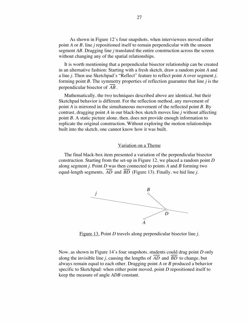
As shown in Figure 12’s four snapshots, when interviewees moved either
point A or B, line j repositioned itself to remain perpendicular with the unseen
segment AB. Dragging line j translated the entire construction across the screen
without changing any of the spatial relationships.
It is worth mentioning that a perpendicular bisector relationship can be created
in an alternative fashion: Starting with a fresh sketch, draw a random point A and
a line j. Then use Sketchpad’s “Reflect” feature to reflect point A over segment j,
forming point B. The symmetry properties of reflection guarantee that line j is the
perpendicular bisector of
!
AB .
Mathematically, the two techniques described above are identical, but their
Sketchpad behavior is different. For the reflection method, any movement of
point A is mirrored in the simultaneous movement of the reflected point B. By
contrast, dragging point A in our black-box sketch moves line j without affecting
point B. A static picture alone, then, does not provide enough information to
replicate the original construction. Without exploring the motion relationships
built into the sketch, one cannot know how it was built.
Variation on a Theme
The final black-box item presented a variation of the perpendicular bisector
construction. Starting from the set-up in Figure 12, we placed a random point D
along segment j. Point D was then connected to points A and B forming two
equal-length segments,
!
AD and
!
BD (Figure 13). Finally, we hid line j.
A
Bj
D
Figure 13. Point D travels along perpendicular bisector line j.
Now, as shown in Figure 14’s four snapshots, students could drag point D only
along the invisible line j, causing the lengths of
!
AD and
!
BD to change, but
always remain equal to each other. Dragging point A or B produced a behavior
specific to Sketchpad: when either point moved, point D repositioned itself to
keep the measure of angle ADB constant.

28
A
B
D
A
B
D
A
B
D
A
B
D
Figure 14. Four snapshots of point D moving along the hidden line j.
CHAPTER VI
MOTION
In Figure 15 lies a quadrilateral. It is a specific quadrilateral with a length of
3.4 inches, a width of 1.3 inches, and sides parallel to the edges of this paper.
None of these particulars matter of course when the quadrilateral applies for
membership in the club of rectangles. For those purposes, only the general
properties of rectangular shapes bear any importance. Two pairs of parallel sides?
Yes. Four right angles? Yes. The quadrilateral is a rectangle.
A
D
B
C
Figure 15. A particular rectangle.
Separating the non-essential particulars of a given rectangle from the universal
properties of all rectangles is something teachers do automatically. But as
described in Chapter III, students, as geometric neophytes, may find a solitary,
static illustration too limiting for reaching generalized conclusions.
Well before the coming of the personal computer and dynamic geometry,
researchers have suggested a way to broaden the information represented in a
single picture: the addition of motion. Art psychologist Rudolf Arnheim writes
in 1969:
The usual illustrations in textbooks and on the blackboard help to make a
problem visible, but they also freeze it at one phase of the range to

29
which the proposition refers. Therefore, they tempt the student to mistake
accidental circumstances for essential ones. The solution is not to
leave out illustrations but either to produce mobile models, for instance,
by means of film animation, or, at least, to use immobile illustrations
in such a way that the student realizes which of their dimensions
are variables. (p. 182)
In describing the educational benefit of setting geometric shapes into motion,
Arnheim concludes, “A static concept has been replaced with a dynamic one.
Generality intended is now represented by generality perceived” (1969, p. 180).
Arnheim’s argument has remained relevant, and indeed gained backing, 32
years later in today’s world of dynamic geometry. The ability of Sketchpad to
display not one rectangle, one square, or one isosceles triangle, but a seemingly
infinite variety of these objects represents to many educators a compelling
example of geometric shapes presented in generalized form (Olive, 2000).
Is this confidence in dynamic geometry well founded? Does DG software
allow students to perceive generalities and cast aside particulars? My interview
analysis suggest that the answer to the second question is at least sometimes no.
In this chapter, I describe how students continued to search for—and found—
particulars amidst Sketchpad’s array of seemingly generalized images. Through
mouse manipulations of onscreen isosceles triangles and rectangles, interviewees
uncovered restrictive movement patterns created not by the dictates of
mathematics, but rather by the uniqueness of Sketchpad’s design. These
restrictions fell into three categories:
1. Certain points moved while others stood still when objects
were dragged,
2. Certain points could only be dragged along hidden paths,
3. Certain points, when dragged, restricted the movements of the objects
upon which they sat.
Throughout this chapter, I offer examples of the above phenomena and describe
how interviewees paid as much, if not more, attention to these particulars than to
the general properties of shapes.
What Moves and What Does Not
Stated broadly, a rectangle constructed with Sketchpad can grow and shrink via
the dragging of the computer mouse. This is a loose description of Sketchpad’s
motion feature; one requiring some elaboration. What does it mean to say a
rectangle “grows and shrinks”?
30
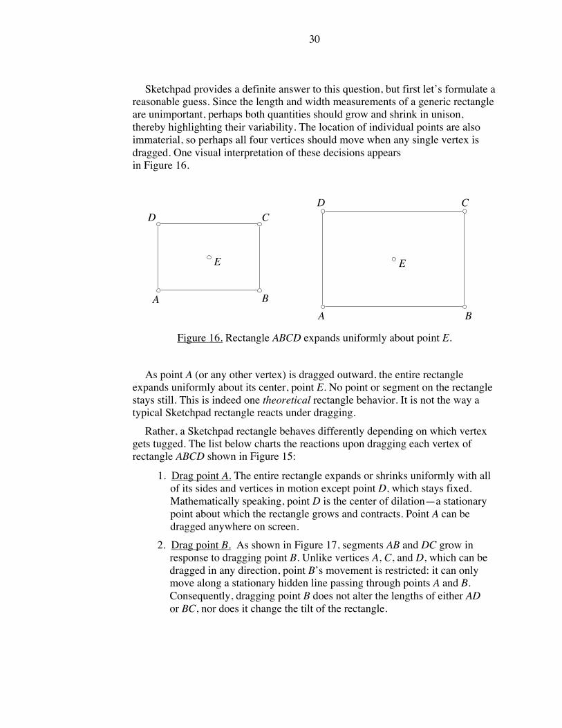
Sketchpad provides a definite answer to this question, but first let’s formulate a
reasonable guess. Since the length and width measurements of a generic rectangle
are unimportant, perhaps both quantities should grow and shrink in unison,
thereby highlighting their variability. The location of individual points are also
immaterial, so perhaps all four vertices should move when any single vertex is
dragged. One visual interpretation of these decisions appears
in Figure 16.
E
BA
D C
E
BA
D C
Figure 16. Rectangle ABCD expands uniformly about point E.
As point A (or any other vertex) is dragged outward, the entire rectangle
expands uniformly about its center, point E. No point or segment on the rectangle
stays still. This is indeed one theoretical rectangle behavior. It is not the way a
typical Sketchpad rectangle reacts under dragging.
Rather, a Sketchpad rectangle behaves differently depending on which vertex
gets tugged. The list below charts the reactions upon dragging each vertex of
rectangle ABCD shown in Figure 15:
1. Drag point A. The entire rectangle expands or shrinks uniformly with all
of its sides and vertices in motion except point D, which stays fixed.
Mathematically speaking, point D is the center of dilation—a stationary
point about which the rectangle grows and contracts. Point A can be
dragged anywhere on screen.
2. Drag point B. As shown in Figure 17, segments AB and DC grow in
response to dragging point B. Unlike vertices A, C, and D, which can be
dragged in any direction, point B’s movement is restricted: it can only
move along a stationary hidden line passing through points A and B.
Consequently, dragging point B does not alter the lengths of either AD
or BC, nor does it change the tilt of the rectangle.

31
A
D
B
C
A
D
B
C
A
D
B
C
Figure 17. Three snapshots of ABCD as point B is dragged to the right.
3. Drag point C. The entire rectangle is translated across the screen without
any change to its dimensions. Point C can be dragged anywhere on
screen.
4. Drag point D. The entire rectangle grows and shrinks about the stationary
center of dilation, point A. Point D can be dragged anywhere on screen.
Note that not one of the movements listed above is identical to the growth
pattern depicted in Figure 16. Nor is this type of behavior limited to rectangles: all
shapes constructed with Sketchpad exhibit similar movement patterns. Each
vertex of an object when dragged will move certain elements of the overall shape
while leaving others stationary.
For educators examining a Sketchpad rectangle, the quirky behavior described
above is perhaps momentarily surprising. More likely, it passes unnoticed. Yes,
point D stays fixed when dragging point A, but this invariant is of no particular
consequence when describing the general properties of rectangles. By contrast,
students in our interviews often paid considerable attention to the stationary
nature of points. The following three examples illustrate this tendency.
David and Ben
The interview excerpts below find David and Ben4 examining two pre-built
isosceles triangles. Chapter V contains a complete description of these triangles,
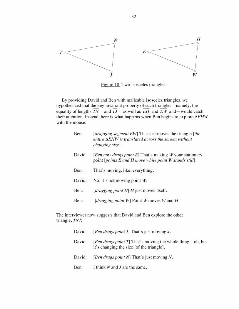
but a picture of them appears again in Figure 18 for reference. Recall that
although these triangles look identical, the behavior of points J and W is different:
whereas dragging point J keeps the lengths of
!
TN and
!
TJ intact, dragging point
W lengthens or shortens
!
EH and
!
EW simultaneously.
4 The names of all students in this dissertation are pseudonyms.
32
T
N
J
E
H
W
Figure 18. Two isosceles triangles.
By providing David and Ben with malleable isosceles triangles, we
hypothesized that the key invariant property of such triangles—namely, the
equality of lengths
!
TN and
!
TJ as well as
!
EH and
!
EW and—would catch
their attention. Instead, here is what happens when Ben begins to explore !EHW
with the mouse:
Ben: [dragging segment EW] That just moves the triangle [the
entire !EHW is translated across the screen without
changing size].
David: [Ben now drags point E] That’s making W your stationary
point [points E and H move while point W stands still].
Ben: That’s moving, like, everything.
David: No, it’s not moving point W.
Ben: [dragging point H] H just moves itself.
Ben: [dragging point W] Point W moves W and H.
The interviewer now suggests that David and Ben explore the other
triangle, TNJ:
David: [Ben drags point J] That’s just moving J.
David: [Ben drags point T] That’s moving the whole thing…oh, but
it’s changing the size [of the triangle].
David: [Ben drags point N] That’s just moving N.
Ben: I think N and J are the same.

33
David: N and J have the same movements.
Ben: Yeah.
In the quotations above, David and Ben make no indication that they recognize
either triangle to be isosceles. Rather, their discussion focuses on causalities
regarding individual points. These causalities are of the type, “Moving point X
causes point Y to move, but leaves point Z stationary.” Notice, however, that
David and Ben do progress beyond a “move/does not move” categorization of
points by mentioning that points N and J “have the same movements” (both N and
J are constrained to a circular path). Asking how a point moves is a
natural follow-up to the simpler question, “Does the point move?” I will
discuss this theme further when revisiting David and Ben’s progress in an
upcoming section.
Rick and Allen
In the conversation excerpted below, Rick and Allen have experimented with
our pre-built rectangle and identified its shape correctly. Their attempt to build a
fresh rectangle from scratch has hit a roadblock, so at the interviewer’s
prompting, they think again about the features they’d like in their construction.
Rick returns to our rectangle (see Figure 15) and drags its vertices as he talks:
Rick: I think we want…all these points to have different
characteristics. Point A moves on point D [Rick drags point A
and sees the rectangle rotate and grow around the stationary
point D]…Point D moves on point A [Rick drags point D,
creating the same behavior].
Allen: That’s also changing the size [of the rectangle].
Rick: Oh it does, yeah…Point C moves the rectangle [Rick drags
point C, thereby translating the rectangle].
Unlike David and Ben, Rick and Allen do know what shape they’re trying to
build. Yet from their perspective, a rectangle must include not only right angles
and parallel sides, but also the specific behaviors associated with each vertex of a
Sketchpad rectangle. The interviewer senses this problem and directs the pair
back on course:
Int.: Don’t worry for the moment about the characteristics of the
points. I think that’s possibly distracting. Think about the
34
shape. What features do you want to preserve in the shape?
Because in fact, the customer doesn’t really care about the
points; the customer cares about the shape.
It is worth mentioning here that the attention of Rick and Allen (as well as
David and Ben) to point behavior may be a by-product of our black-box interview
style. Since interviewees were told they would need to duplicate our onscreen
objects, this directive could be seen as extending to all aspects of the
construction—including points. More will be said about this issue in the
concluding chapter.
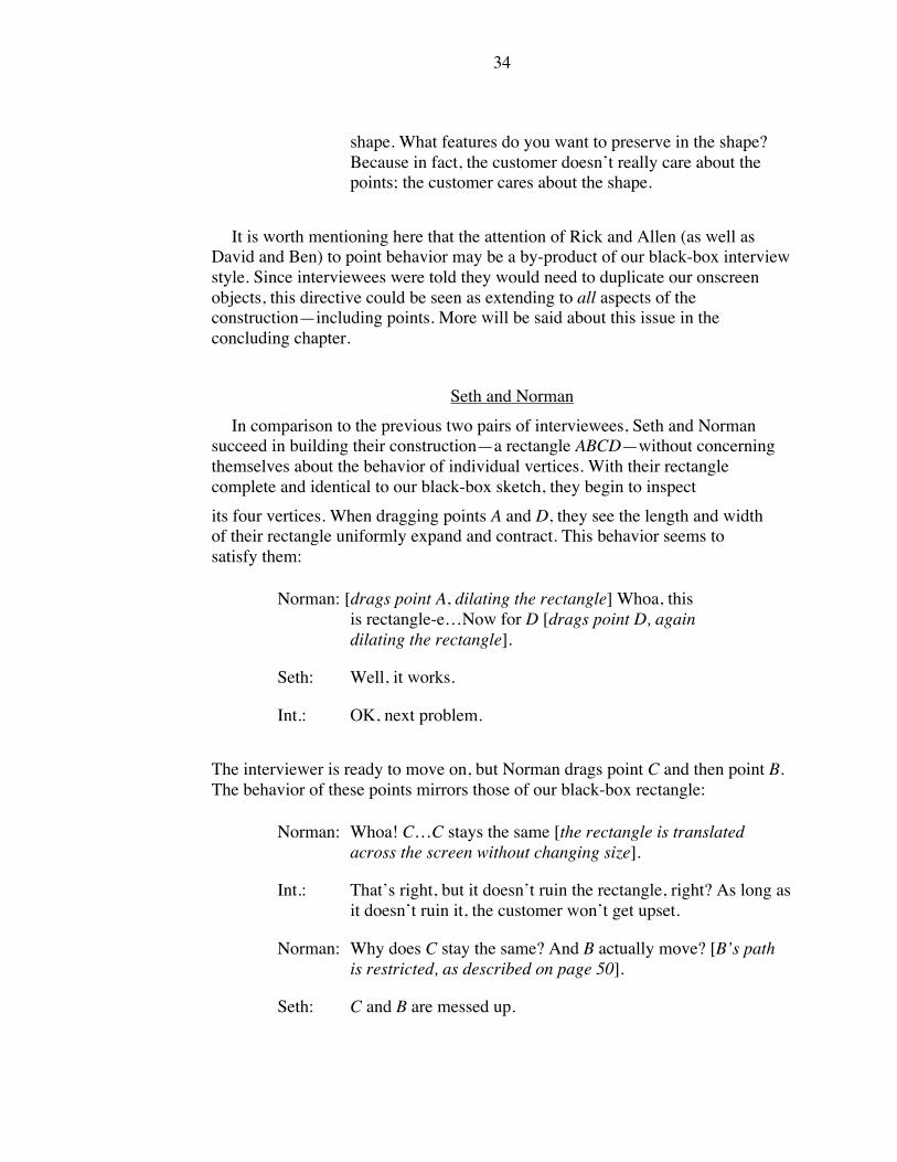
Seth and Norman
In comparison to the previous two pairs of interviewees, Seth and Norman
succeed in building their construction—a rectangle ABCD—without concerning
themselves about the behavior of individual vertices. With their rectangle
complete and identical to our black-box sketch, they begin to inspect
its four vertices. When dragging points A and D, they see the length and width
of their rectangle uniformly expand and contract. This behavior seems to
satisfy them:
Norman: [drags point A, dilating the rectangle] Whoa, this
is rectangle-e…Now for D [drags point D, again
dilating the rectangle].
Seth: Well, it works.
Int.: OK, next problem.
The interviewer is ready to move on, but Norman drags point C and then point B.
The behavior of these points mirrors those of our black-box rectangle:
Norman: Whoa! C…C stays the same [the rectangle is translated
across the screen without changing size].
Int.: That’s right, but it doesn’t ruin the rectangle, right? As long as
it doesn’t ruin it, the customer won’t get upset.
Norman: Why does C stay the same? And B actually move? [B’s path
is restricted, as described on page 50].
Seth: C and B are messed up.

35
Norman: Yeah.
Seth: Points A and D work great.
From these quotations, it appears that Seth and Norman would like all four
vertices to grow and shrink their rectangle. The more restrictive behavior of C and
B leads Seth to pronounce them “messed up.”
Uncovering Hidden Paths
The preceding three examples spotlighted students’ attention to the mobility
and immobility of individual points. Such point behaviors—pure artifacts of
Sketchpad’s design—did little to aid interviewees in uncovering and recreating
the generalized mathematical properties of each mystery shape.
In this section, I present two further examples highlighting students’ attention
to point behavior. Now, however, their interest lies not merely in determining
whether a given point moves, but rather, in describing how a point moves when
dragged.
Consider vertex N of isosceles triangle TNJ in Figure 18. From this static
picture alone, there is no reason to suppose that one couldn’t take the computer
mouse, click on point N, and drag it randomly across the screen. Testing this
theory yields a surprise: point N’s behavior (as well as point J’s) is restricted to an
unseen circle with center at point T and radius of length TN. See Figure 19.
T
N
J
Figure 19. A hidden circle represented by dashed segments.
The circle, tucked away from sight until one chooses Sketchpad’s “Show All
Hidden” menu option, functions similarly to an architect’s blueprints. Just as most

36
of us remain cheerfully oblivious to the construction features buried behind our
walls, so do we not see the circle once the constructor has hidden it. The circle
provides the scaffolding needed to build an isosceles triangle without calling
undue attention to itself.
Prior to the start of our interviews, we hid the circles that formed the backbone
of our isosceles triangles. To our surprise, interviewees soon
found them.
David and Ben Revisited
This chapter began by describing David and Ben’s exploration of an isosceles
triangle. Recall that the pair had dragged individual vertices of their triangle, but
had not identified it as isosceles. Sensing that they needed a little help, the
interviewer provides a big hint:
Int.: How about the lengths of some of the segments? Is there
anything about those that stay the same?
David: These two lengths stay the same [pointing onscreen to TN and
TJ, Figure 18].
Ben: Yeah it’s always a…what is it? An isosceles or whatever?
David and Ben now attempt to build their own isosceles triangle. They draw
(as opposed to construct) a triangle that looks isosceles, but they cannot keep two
lengths equal when dragging its vertices. At this stage, David and Ben still do not
realize that a circle is necessary to assure the equality of lengths.
Ben now returns to our pre-built isosceles triangle, TNJ. He begins to drag
point N. His mouse movements, slow and tentative at first, cause N to rock back
and forth along a small arc of the hidden circle (Figure 19). Point N vacillates in
this manner for approximately seven times, never spanning more than half the
entire circle’s arc.
David and the interviewer continue to talk while Ben stares at point N’s
movement. Soon Ben interjects, “OK, that’s a circle!” Once Ben announces his
discovery, he begins to move point N rapidly, now twirling it around the entire
circle. Ben spins the point again and again, as if to confirm his statement.
David is quick to understand the significance of Ben’s observation:
David: Oh, OK, there we go. That helps. So that’s the center point of
the circle [gestures at point T].

37
The pair now construct their own isosceles triangle, complete with hidden circle,
without difficulty.
Ellen and Lynne
Ellen and Lynne pursue their isosceles triangle investigation (Figure 18) in a
manner virtually identical to David and Ben:
Lynne: [dragging point H in a full circle] When H moves, oh, I think
H is on a circle or something. So the circle is hidden, [and]
when H moves, it is attached to the circle and it moves only in
a circle.
Int.: Why do you say that?
Lynne: Because when you move E, you can move it in [towards W]
and you can move it anywhere, but H is restricted, you can’t
move it into the center, and it seems to go around in a kind of
a circular motion.
Int.: So basically you’re saying you think it’s a circle because it
kind of looks like one.
Ellen: It’s like a protractor [makes a circular motion with her hands
that resembles a compass].
Lynne: Yeah.
With some effort, Ellen and Lynne reconstruct both isosceles triangles. At no
time, however, do the pair identify the triangles as isosceles or mention the
equality of lengths. The interviewer does not press them on this matter, so it
cannot be said whether they recognize the general properties of their two
triangles. Yet like David and Ben, Ellen and Lynne certainly use their discovery
of the hidden circle as an entry point into the construction process.
Commentary
As the examples above illustrate, the detective work of uncovering hidden
paths provided an effective, if unexpected, route to rebuilding constructions from
scratch. Prior to the interviews, we hypothesized that a student who successfully
explored and recreated isosceles triangle TNJ might perform the following
hypothetical line of reasoning:
Hmmm…By dragging the vertices of triangle TNJ and watching the entire
triangle grow and shrink, I see certain key features of its shape remain

38
invariant. In particular, two of its lengths, TN and TJ, always stay equal to
each other. That must mean I’m dealing with an isosceles triangle. So how
can I build one of my own? Well, a circle is a good tool to use when I
need to guarantee the equality of two lengths. Let’s try that…
There are several assumptions contained in this thought process:
1. Sketchpad’s seemingly infinite supply of generalized isosceles triangles
would help students to perceive visible invariants. Interviewees would pay
attention to such visible geometric invariants as the equality of TN and TJ
when viewing !TNJ.
2. Faced with the need for creating two equal sidelengths, interviewees
would puzzle out in their minds the necessary geometric construction.
During our interviews, this chain of events did not occur. Interviewees broke with
the above assumptions in the following ways:
1. Interviewees did not (except in one case when prompted) inform us that
the lengths of TN and TJ remained equal or note !TNJ was isosceles.
2. Interviewees paid particular attention to invariants that were invisible. In
particular, Point N was restrained in its movement to a hidden circle.
Rather than deduce on their own the mathematical need for a circle,
interviewees uncovered the circle through dragging and observing point
N’s path.
3. Interviewees did not seem to consider their task as building an isosceles
triangle with two equal lengths. Rather, their view of the triangle
construction was tied to the hidden circle: build a triangle whose two
vertices travel along the circumference of a circle, and whose third vertex
serves as the circle’s center. This definition has embedded within it the
properties that assure the triangle is isosceles and contains two equal
lengths, but these traits were never mentioned explicitly.
Reducing the Generality of a Dynamic Illustration
Earlier in this chapter, I described the various ways a Sketchpad rectangle
ABCD reacts when tugged on each of its vertices. Dragging point A produces a
seemingly infinite number of rectangles, three of which are shown below in
Figure 20:

39
A
D
B
CA
D
B
C
A
D
B
C
Figure 20. Three general snapshots of rectangle ABCD.
The snapshots above illustrate rectangle ABCD in a general form. The
numerical values of its length and width vary from picture to picture, as does the
tilt of the rectangle on the page.
By contrast, dragging point B yields a more restricted range of rectangles,
illustrated again in Figure 21 below:
A
D
B
C
A
D
B
C
A
D
B
C
Figure 21. Dragging point B restricts the movement of ABCD.
As B is dragged to the right in a sliding, trombone-like fashion, certain features
of the rectangle remain invariant. The lengths of AD and BC do not change; the
distance between parallel lines DC and AB stays constant; the rectangle does not
tilt. The progression of rectangles in Figure 21 displays more generality than a
single rectangle image, but less generality than the snapshots in Figure 20. The
interview excerpts below describe how interviewees sometimes preferred the
reduced generality of Figure 21.
Lynne
Lynne begins her study of rectangle ABCD by dragging each vertex
individually. She experiments with vertices A and D—the two points that change
the length, width, and tilt of the rectangle—but says she’s “not really sure about
these yet.” She does, however, repay several visits to vertex B, examining

40
both the restricted movement of the point and the rectangle (Figure 21).
Lynne comments:
Lynne: I think that B must be on…I think there might be like a
parallel line or something going…going this way [motioning
with her finger in the direction of segment AB]. Point B can’t
really adjust; it only stays in the same…never mind.
Int.: What suggested the parallel to you?
Lynne: I think the fact that when you select B it does not move in the
way the others do [pointing to A and D]. Point B can’t adjust
like that. It can only adjust this way, keeping the same lengths
[pointing to segments AD and BC, both of which maintain the
same lengths when B is dragged].
In her final quotation above, Lynne mentions that the lengths of
!
AD and
!
BC
remain constant while dragging point B. Noticing the invariance of these two
lengths (and point B’s inability to move closer to
!
DC ) might be helping her to see
that
!
AB and
!
DC are parallel. Whereas dragging point A or D changes the tilt
and the distances between both pairs of ABCD’s parallel sides, dragging point B
restricts this generality, perhaps allowing Lynne to focus on just the one pair of
parallel sides.
Rick and Allen Revisited
Recall that when we checked the progress of Rick and Allen, they had been
unsuccessful in their attempts to build rectangle ABCD. When Rick dragged
points A and D, the rectangle’s length and width expanded and contracted, but he
paid attention to the stationary nature of the points instead:
Rick: Point A moves on point D [Rick drags point A and sees the
rectangle rotate and grow around the stationary point
D]…Point D moves on point A [Rick drags point D, creating
the same behavior].
When Rick drags point B (Figure 21), he notices more essential features of the
rectangle:
Rick: I think we want to keep all the angles 90 degrees, and we want
to keep the lines parallel…these horizontal lines [pointing to
!
AB and
!
DC ].

41
As with Lynne, Rick seems to focus on the one pair of parallel segments that
grows and shrinks when point B is dragged.
Commentary
By dragging point B and restricting the movement of their Sketchpad
rectangles, both Rick and Lynne exhibit behavior resembling the “prototype
phenomenon” described in Chapter III. Recall that students, when presented with
a static image such as an isosceles triangle, were more successful in identifying
the object when it sat with its base horizontal to the paper (Figure 4). Textbooks,
whose images are often limited to such “prototypic” positions, had unwittingly
narrowed students conceptions of what counted as isosceles.
Here now, in the case of dynamic geometry and rectangle ABCD, students are
engaging in some narrowing of their own, restricting the types of rectangles they
see to make it simpler to identify the quadrilateral’s features.
Indeed it might be unrealistic to expect that students can attend to the necessary
attributes of a rectangle (or other shape, for that matter) when all of its sides grow,
shrink, or rotate simultaneously. Just because we can create an idealized rectangle
with near-complete variability does not mean, from a pedagogical standpoint, that
we should. Perhaps the restrictive rectangle represents a valuable middle ground,
where generality is tempered by some specificity.
CHAPTER VII
LANGUAGE
Chapter VI examined the influence of motion on the geometric explorations
conducted by our interviewees. In this chapter, the focus shifts to issues of
language. What verbal descriptions did interviewees use to describe the images
they observed on screen? Was their language that of traditional geometry or more
informal in nature?
In these language-related issues, motion will continue to play an important
role. Chapter III described a theory of “situated description” whereby students
who work with computers adopt language reflecting the types of interactions
promoted by the software. The Geometer’s Sketchpad promotes motion-based
interactions with malleable geometric figures. As such, interviewees’ choice of
words and descriptions were often tied to the motion they viewed onscreen.

42
Motion-Based Descriptions of Parallelism
Among its other traits, a rectangle possesses two pairs of parallel sides.
Without using the word “parallel” explicitly, one might say the sides have the
same slope. Or one could note that if the sides were extended indefinitely, the two
resulting lines would never intersect.
This section presents two interviewees whose descriptions of a
rectangle’s parallel sides were neither of the familiar possibilities offered above.
Rather, their words show the influence of working within Sketchpad’s motion-
centered environment.
Interviewee Ben draws a quadrilateral ABCD that looks nearly rectangular. He
uses no construction tools, so dragging any vertex will deform ABCD into an
arbitrary quadrilateral. When Ben tugs on his quadrilateral, he realizes that has not
constructed a rectangle. As he drags point A to various locations (seen in Figure
22’s three snapshots), he talks about the behavior he would like to see from
ABCD:
Ben: Well, it’s not exactly a rectangle, but if you move point A out
[Figure 22(i)], then D has to come out with it. If you move
point A up [Figure 22(ii)], B has to come. If you move point A
diagonal [Figure 22(iii)], then they [points B and D] have to
go up and to the side.
D C
BA
D C
B
A
D C
B
A
(i) "out" (ii) "up" (iii) "diagonal"
Figure 22. The results of moving point A “out, up, and diagonal.”
Ben’s quotation adopts a “follow-the-leader” description of how a proper
rectangle should behave. When point A slides “out” to the left (Figure 22(i)), then
point D has to “come out with it.” When point A moves up (Figure 22(ii)), then
point B must follow suit. Finally, if point A moves in a northwest direction
(Figure 22(iii)), then points B and D must move north and west, respectively.

43
All of the actions described here can be encapsulated into a single, more formal
statement: regardless of point A’s location, opposite sides of ABCD must remain
parallel.
Rick, in a separate interview, describes parallelism much the same as Ben. He
draws—as opposed to constructs—a rectangle ABCD. When he drags point A and
sees that point D does not move with it (Figure 23) he says, “Somehow [points A
and D] need to be attached so that when I pull on point A, both A and D move this
way or that.”
A
D C
B A
D C
B
Figure 23. When point A is dragged, point D does not follow.
Ben and Rick’s language, while unexpected, does describe parallelism in a
dynamic geometry environment. Their words lack specificity, and it is here that a
teacher can press students on the issue: when point A moves, where exactly
should point D move? As point A moves, what features of the rectangle should be
kept intact? Research results and classroom experience can help teachers develop
their own internal database of DG-inspired language and prepare them to
capitalize on situations where such language is used.
In the next section, the study of language turns to two DG-related metaphors
devised by our interviewees. It is here with metaphors that we will see how
language can serve as either a barrier or an entryway into geometric constructions.
Movement-Based Metaphors
Simple and abstract, a static circle or rectangle can serve as the basis for
countless metaphors. A circle might trigger an image of a Frisbee; a rectangle
might resemble a door. In both instances, it is the object’s shape that inspires
the association.
A broader role for metaphor emerges in the world of dynamic geometry. Each
object created with The Geometer’s Sketchpad possesses not only a shape, but a
movement associated with the dragging of its parts. Together, shape and
movement may suggest metaphors not apparent through a static picture alone.

44
This section offers two metaphors that arose during interviewees’ exploration
of our black-box sketches. While both metaphors had the potential to aid in the
identification and reconstruction task, only the pair of Ellen and Lynne were able
to use their metaphor effectively. What factors contributed to their success? Why
did our other interviewee, Norman, encounter more difficulty? The interview
excerpts and analyses point to some intriguing possibilities.
Ellen and Lynne
Figure 24 shows four snapshots of our final black-box sketch. Chapter V
describes this construction in detail, but in brief, point D sits on a hidden line j
that is the perpendicular bisector of segment AB. Lengths AD and BD are always
equal.
A
B
D
A
B
D
A
B
D
A
B
D
Figure 24. Four snapshots of point D moving along the hidden line j.
Lynne begins her investigation of Figure 24 by dragging points A, B, and D.
Her partner, Ellen, comments on the movement of point D:
Ellen: It’s like one of those like…what do you call them? Slingshots.
You throw a rubber band and then it…[moves her hand back
and then forward as if tightening and releasing a rubber
band]…When you move D, it does a little slingshot thing…
Int.: What makes it look like a slingshot to you?
Lynne: A slingshot? Well, OK, I was thinking about looking at a
slingshot from the top…You know, how it's like a ‘Y’? [uses
her hands to trace a big ‘Y’ in the air]. That’s the two points
of the ‘Y’ [points A and B] from the top and point D is the
rubber band.
As a metaphor for capturing the movement of point D, Ellen’s choice of a
slingshot is an apt one. Figure 25 shows a ‘Y’-shaped slingshot with tips at points
A and B and a stretched rubber band between them. The center of the rubber band,

45
point D (the contact point for a wad of gum or other projectile), does move like its
onscreen Sketchpad counterpart.
Ellen’s slingshot metaphor serves as conversational shorthand for what would
otherwise be a lengthier geometric description. After listening to Ellen’s
explanation above, Lynne offers such a geometric take on the situation:
Lynne: I think I might have an idea…I think that points A and B are
on the same line…they are perpendicular to a different line
that point D is on.
D
B
A
Figure 25. A slingshot model of the construction in Figure 24.
Lynne illustrates her statement by moving Sketchpad’s selection arrow
between points A and B to indicate the hidden segment connecting them. She then
moves the arrow in the direction of the hidden perpendicular bisector, line j
(Figure 13).
Lynne is correct; her geometric analysis will allow her to reconstruct the
sketch. At this point, it would be natural enough for the interviewer to forgo
Ellen’s informal metaphor in favor of Lynne’s more familiar approach. Instead,
he challenges the pair to reconcile their two, complementary views of the
situation. He addresses Lynne:
Int.: Describe your thing again. You [Ellen] see if you can, while
she’s describing it, see if you can picture your slingshot. See if
the things Lynne describes fits that picture. Because I’m
curious. You have one image, [Ellen] has another image. They
both are clearly describing what each of you are seeing. The
question is whether you’re seeing the same thing.
46
The interviewer has asked Lynne to repeat her explanation, but she offers more,
tying her geometric description to Ellen’s slingshot model:
Lynne: One of the reasons it looks most like a slingshot is because it
doesn’t curve everywhere. It just stays in the same straight
path.
The center of a slingshot’s rubber band pulls straight back and springs straight
forward. Its path is not “curvy.” Geometrically speaking, point D moves along a
line.
Lynne: When D is passing through A and B like a slingshot, it doesn’t
go closer to A or closer to B. It just stays in the center of them
both…[drags point D so that it forms one continuous segment
ADB with D at the midpoint]…It would make sense [dragging
point A as she speaks] because everywhere, if you can
imagine, the straight line there [gesturing with her hand to
indicate the hidden perpendicular bisector line j], they [the
lines] would always be perpendicular.
In the above quotation, Lynne explains that regardless of the location of slingshot
tips A and B, the path of point D will always be perpendicular to segment AB.
The interested reader will find an extended excerpt from this interview in
Appendix D.
Commentary
When the interviewer asks Ellen to explain her slingshot idea, it is simple
enough for her to mimic a slingshot’s movement with her hands. The ultimate test
of her metaphor, however, comes in what might be called the “translation phase”
of the task. Recreating a slingshot-like movement with Sketchpad requires Lynne
to examine how a slingshot’s movement can be coded into the language of
geometry. Such translation work is a new skill, one not required in traditional,
static geometry.
In the second interview excerpted below, Norman must also translate his
informal observations into geometric terminology. He fares less well than Lynne.

47
Norman
Figure 26 shows four snapshots of our perpendicular bisector sketch. Chapter
V describes this sketch in detail, but in brief, the line between A and B is the
perpendicular bisector of a hidden segment connecting the two points.
Norman explores the construction by dragging point A with his mouse:
Norman: [dragging point A to point B] That’s weird. How does it do
that? How does it [point A] keep away from the line? It’s like
a magnet to the line. As I get it closer [point A closer to point
B], the line moves farther away. And if I really try hard, I can
get [the points] to come together in the center [drags point A
onto point B]…But how does it do that?
The interviewer asks Norman to expand upon his magnet metaphor. Norman
drags point B as he speaks:
Norman: …this [point A] seems to be the pressure point…Only [there]
can the dot [point B] touch the line.
Int.: So now describe the line in relation to the two dots…
Norman: …as you push [the line] with this dot [point B], it moves
towards the other dot [point A]. Any way you do it [he
illustrates that regardless of where point B begins, the line is
“pushed” towards point A as point B is dragged to point A].
A
B
A
B
A
B
AB
Figure 26. Four snapshots of the perpendicular bisector construction..
Later in the conversation, the question of whether Sketchpad has a command or
menu item that creates magnet-like behavior arises:
Int.: You know what? Figuring out the software is not the object of
this exercise. You can ask any questions about the software.
48
You tell me what it is that you want to do. You want these
points to do something.
Norman: I want these points to interact with the line.
Int.: OK, in what way? Describe the relationship that you want.
Norman: Like, when the point moves nearer to the line, the line moves
away and towards the other point.
Int.: There’s no instruction that I know of that does exactly that.
The interested reader will find an extended excerpt of this interview in
Appendix D.
Commentary
Norman’s description of the perpendicular bisector construction is not without
merits. His descriptions of the onscreen behaviors are accurate. As point A
approaches point B, the line moves away from A. And point A can only touch the
line when the two points, A and B, coincide.
With these observations in hand, Norman must answer an important question:
what accounts for these movements? He couches his descriptions in terms of
magnetism.
As one drags point A in the direction of point B, it certainly does feel as if the
point “pushes” (to use Norman’s word) the line away. If this black-box
arrangement appeared as part of a physics simulation, then associating the
pushing to a magnetic force might serve Norman well. One could imagine
Norman selecting a magnetism option from the software’s menu items to simulate
such behavior.
But Sketchpad operates under the rules of geometry, and geometry knows
nothing of pushing or magnets. There are no menu items corresponding to
“pushing” and “pressure points.” Norman must, as did Lynne, translate his
observations from a physical model to the corresponding language of geometry.
Why does it feel like point A pushes the line away? Because the line always
passes through the midpoint of segment AB. See Figure 27:

49
A B A B A B
Figure 27. Three snapshots showing point A approaching point B.
Movement-inspired metaphors such as Ellen’s slingshot and Norman’s magnet
both serve as potential entries into the process of deconstructing the geometry that
lies behind black-box sketches. But users must recognize metaphors as informal,
transitional tools to be reinterpreted in terms of formalized geometry. For
Norman, who says that if he “really tries hard” he can bring points A and B
together, the magnetism interpretation may be very real to him and not a metaphor
at all.
CHAPTER VIII
CONSTRUCTION
With their attention to issues of language and motion, Chapters VI and VII
focused on interviewees’ investigative mouse dragging. Now, in this final analysis
chapter, the spotlight shifts to their efforts at rebuilding black-box constructions
from scratch. Specifically, it details the work of several interviewees as they
assemble a Sketchpad square.
Compared to other geometric shapes, a square is a relatively simple object to
construct, typically built with the aid of Sketchpad’s circle tool and its
Perpendicular and Parallel Line commands. The interviews excerpted below,
however, offer student construction techniques that depart from standard methods.
With each technique comes the same question: have the interviewees built a
square? While this may sound like a simple matter to answer, it is, in fact, a
thornier issue than one might suppose in the world of dynamic geometry.
What Qualifies as a Sketchpad Square?
Chapter III presented a structure for classifying constructions in a dynamic
geometry setting. Recall three of Finzer and Bennett’s (1995) construction
categories: drawing, underconstraint, and appropriate constraints.

50
Figure 28 shows a square that reveals itself to be a drawing when points B and
D are dragged. In this instance, the supposed square was created by eyeballing the
location of four segments so they would appear equal in length and positioned at
right angles. Without any geometric constraints built into the picture, any
perturbation to the object deforms it into an arbitrary quadrilateral.
A B
CD
D
C
B
A
Figure 28. ABCD looks like a square, but isn’t.
Figure 29 shows an underconstrained square. It has four built-in right
angles, but no constraints to keep its lengths equal. Dragging vertex B deforms the
square into a rectangle.
A B
CD
A B
CD
Figure 29. ABCD looks like a square, but is actually a rectangle.
Finally, Figure 30 shows a common method for building a bona fide square
with appropriate constraints. Segments DA and DC are radii of a circle, ensuring
the equality of ABCD’s lengths. Segments AB and CB are constructed
perpendicular to DA and DC respectively, guaranteeing that all four of the
quadrilateral’s angles measure ninety degrees. With these construction features in
place, ABCD may grow or shrink when tugged on a vertex, but will always
remain square.
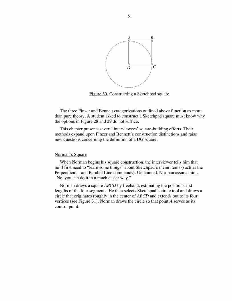
51
A B
CD
Figure 30. Constructing a Sketchpad square.
The three Finzer and Bennett categorizations outlined above function as more
than pure theory. A student asked to construct a Sketchpad square must know why
the options in Figure 28 and 29 do not suffice.
This chapter presents several interviewees’ square-building efforts. Their
methods expand upon Finzer and Bennett’s construction distinctions and raise
new questions concerning the definition of a DG square.
Norman’s Square
When Norman begins his square construction, the interviewer tells him that
he’ll first need to “learn some things” about Sketchpad’s menu items (such as the
Perpendicular and Parallel Line commands). Undaunted, Norman assures him,
“No, you can do it in a much easier way.”
Norman draws a square ABCD by freehand, estimating the positions and
lengths of the four segments. He then selects Sketchpad’s circle tool and draws a
circle that originates roughly in the center of ABCD and extends out to its four
vertices (see Figure 31). Norman draws the circle so that point A serves as its
control point.
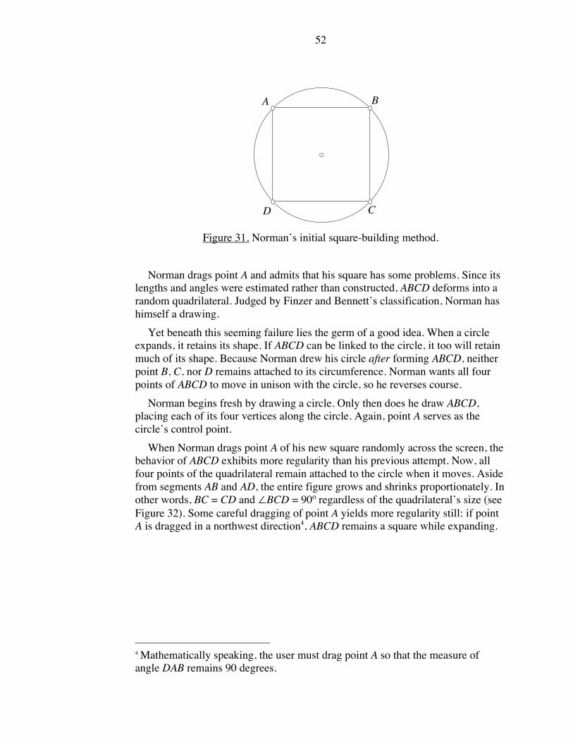
52
A B
CD
Figure 31. Norman’s initial square-building method.
Norman drags point A and admits that his square has some problems. Since its
lengths and angles were estimated rather than constructed, ABCD deforms into a
random quadrilateral. Judged by Finzer and Bennett’s classification, Norman has
himself a drawing.
Yet beneath this seeming failure lies the germ of a good idea. When a circle
expands, it retains its shape. If ABCD can be linked to the circle, it too will retain
much of its shape. Because Norman drew his circle after forming ABCD, neither
point B, C, nor D remains attached to its circumference. Norman wants all four
points of ABCD to move in unison with the circle, so he reverses course.
Norman begins fresh by drawing a circle. Only then does he draw ABCD,
placing each of its four vertices along the circle. Again, point A serves as the
circle’s control point.
When Norman drags point A of his new square randomly across the screen, the
behavior of ABCD exhibits more regularity than his previous attempt. Now, all
four points of the quadrilateral remain attached to the circle when it moves. Aside
from segments AB and AD, the entire figure grows and shrinks proportionately. In
other words, BC = CD and "BCD = 90º regardless of the quadrilateral’s size (see
Figure 32). Some careful dragging of point A yields more regularity still: if point
A is dragged in a northwest direction4, ABCD remains a square while expanding.
4 Mathematically speaking, the user must drag point A so that the measure of
angle DAB remains 90 degrees.

53
A B
CD
AB
CD
Figure 32. The result of dragging point A.
Commentary
Norman’s square-building technique stays clear of the Perpendicular and
Parallel Line construction tools. Without the use of these menu items, it is hard to
imagine how anything he builds could rise above the category of drawing. Yet
through the clever use of a circle, he manages to build a quadrilateral ABCD that
grows and shrinks, all the while approximating a square, provided point A moves
in a controlled path.
Norman’s efforts fall short of an appropriately constrained object, but there is
still much to admire in his work. Compared to the underconstrained square in
Figure 29, his construction holds several advantages:
1. Economy and speed. Building Figure 29’s underconstrained square
demands multiple trips to Sketchpad’s Perpendicular and Parallel Line
commands. It also requires the user to hide construction lines and replace
them by segments. By contrast, Norman’s method involves no hidden lines
and no menu selections. It can be completed in less than half a minute,
qualifying it as a quick-and-dirty means of illustrating a multitude of
squares.
2. Mathematical integrity. None of the construction elements built into Figure
29’s underconstrained square help to keep its four sides equal in length. By
contrast, Norman’s method uses the symmetry of a circle to achieve four
(sometimes) equal lengths.
Because Norman’s construction exhibits square behavior, one might classify it
as an underconstrained square. This assessment, however, leaves room for
disagreement. Norman drew his square by eyeballing the correct locations for its
vertices. As such, the angle measures of ABCD were not precisely ninety degrees,
and its lengths were not perfectly equal. These inaccuracies can be corrected by
measuring and adjusting the particulars of ABCD, but is measuring a legitimate
part of the construction process? Traditionalists would likely say no.
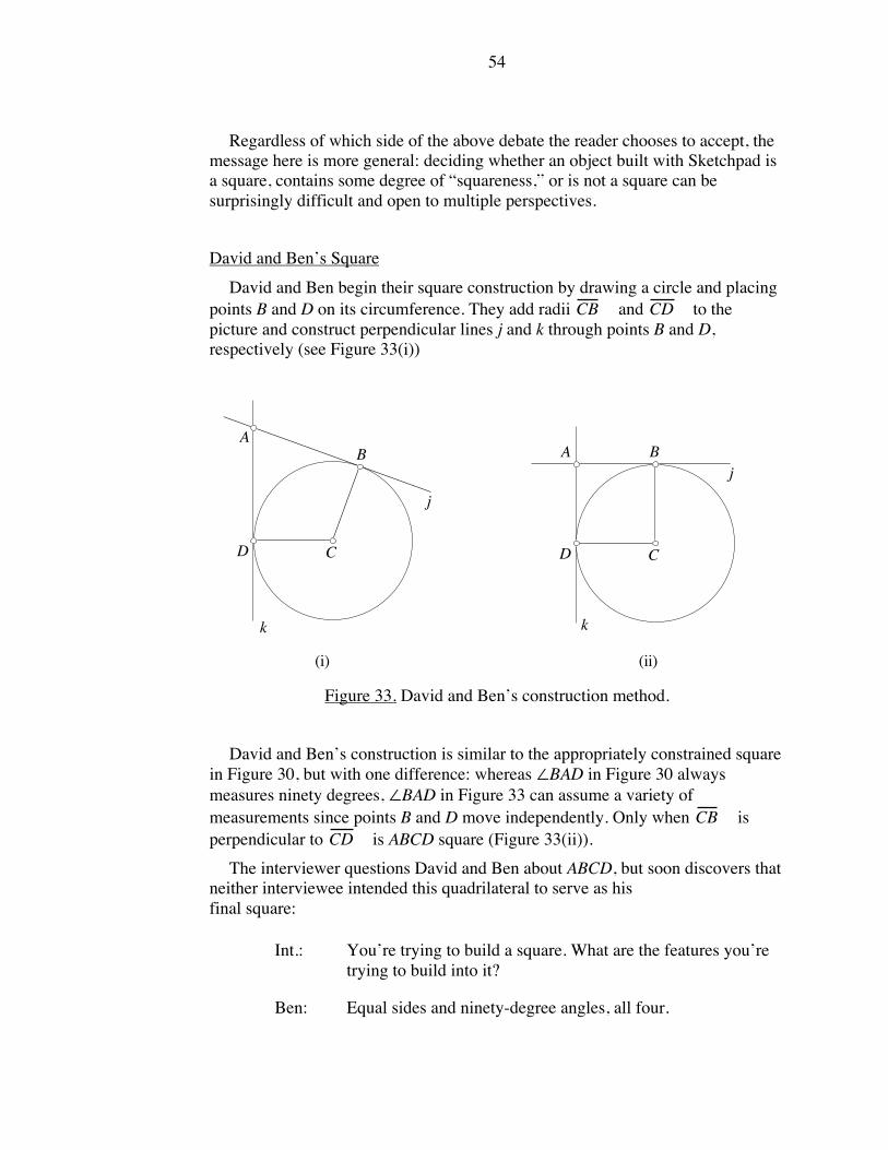
54
Regardless of which side of the above debate the reader chooses to accept, the
message here is more general: deciding whether an object built with Sketchpad is
a square, contains some degree of “squareness,” or is not a square can be
surprisingly difficult and open to multiple perspectives.
David and Ben’s Square
David and Ben begin their square construction by drawing a circle and placing
points B and D on its circumference. They add radii
!
CB and
!
CD to the
picture and construct perpendicular lines j and k through points B and D,
respectively (see Figure 33(i))
(ii)(i)
k
j
D C
BA
k
j
D C
BA
Figure 33. David and Ben’s construction method.
David and Ben’s construction is similar to the appropriately constrained square
in Figure 30, but with one difference: whereas "BAD in Figure 30 always
measures ninety degrees, "BAD in Figure 33 can assume a variety of
measurements since points B and D move independently. Only when
!
CB is
perpendicular to
!
CD is ABCD square (Figure 33(ii)).
The interviewer questions David and Ben about ABCD, but soon discovers that
neither interviewee intended this quadrilateral to serve as his
final square:
Int.: You’re trying to build a square. What are the features you’re
trying to build into it?
Ben: Equal sides and ninety-degree angles, all four.

55
Int.: Check this thing out by moving it in various ways. And find
out whether any of the properties that you’re looking for are
there. For example, you do have some ninety-degree angles
that stay all the time.
Ben: Well, we don’t have a full square yet so we can’t really tell.
David: Yeah we do. That’s a full square [points to ABCD].
Ben: Oh yeah. I wasn’t looking at that part.
David: Actually, I wasn’t really thinking of that [either]. I was
thinking we’d go all the way around it [the circle].
Ben: Yeah, I was too.
David and Ben plan to build a square that circumscribes (goes “all the way
around”) their circle. They resume their construction by placing points E and F on
the circle’s circumference, drawing
!
CE and
!
CF , and constructing lines
perpendicular to the two segments (see Figure 34(i)).
FF
(ii)(i)
ED C
BA
E
D C
BA
Figure 34. David and Ben continue their square construction.
By dragging points E and F to their proper locations, David and Ben are able to
make their quadrilateral look like a square (see Figure 34(ii)). Of course any
subsequent dragging of either D, B, E, or F will deform the square back into an
arbitrary quadrilateral.
At this point, the interviewer intervenes, explaining that since segments BF and
DE were drawn (as opposed to constructed) perpendicular to each other, the
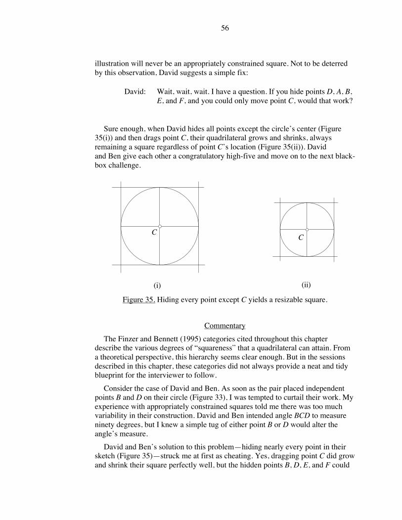
56
illustration will never be an appropriately constrained square. Not to be deterred
by this observation, David suggests a simple fix:
David: Wait, wait, wait. I have a question. If you hide points D, A, B,
E, and F, and you could only move point C, would that work?
Sure enough, when David hides all points except the circle’s center (Figure
35(i)) and then drags point C, their quadrilateral grows and shrinks, always
remaining a square regardless of point C’s location (Figure 35(ii)). David
and Ben give each other a congratulatory high-five and move on to the next black-
box challenge.
CC
(i) (ii)
Figure 35. Hiding every point except C yields a resizable square.
Commentary
The Finzer and Bennett (1995) categories cited throughout this chapter
describe the various degrees of “squareness” that a quadrilateral can attain. From
a theoretical perspective, this hierarchy seems clear enough. But in the sessions
described in this chapter, these categories did not always provide a neat and tidy
blueprint for the interviewer to follow.
Consider the case of David and Ben. As soon as the pair placed independent
points B and D on their circle (Figure 33), I was tempted to curtail their work. My
experience with appropriately constrained squares told me there was too much
variability in their construction. David and Ben intended angle BCD to measure
ninety degrees, but I knew a simple tug of either point B or D would alter the
angle’s measure.
David and Ben’s solution to this problem—hiding nearly every point in their
sketch (Figure 35)—struck me at first as cheating. Yes, dragging point C did grow
and shrink their square perfectly well, but the hidden points B, D, E, and F could

57
“mess up” the shape. Was it fair to remove these points from view, thus making
them inaccessible to mouse dragging?
Strictly speaking, yes. Hiding extraneous construction points is perfectly legal
under the laws of Sketchpad constructions. Dragging any of the quadrilateral’s
vertices such as point A does maintain its square shape, so from this perspective, it
is difficult to argue with David and Ben’s technique.
But Ben made a remark prior to starting his next black-box item that caused me
some concern. He asked, “Is that the only way to get it [the square]?” Throughout
this dissertation, I have explained how the tools of dynamic geometry are not
identical to their traditional counterparts. How one constructs a square with
Sketchpad is not identical to straightedge and compass. Yet despite its
differences, Sketchpad does maintain the mathematical integrity of the
construction. Aside from knowing how to use such Sketchpad commands as
“Perpendicular Line” and “Parallel Line,” there are no special software tricks
needed to build a DG square.
Sketchpad’s square construction is no less mathematical than the steps required
for straightedge and compass. For Ben to think that he needed to hide
misbehaving points struck me as unfortunate. If David and Ben had constructed
(as opposed to drawn) segments BF and DE perpendicular to each other, then
there would be no need to hide points. Any point, visible or otherwise, would
maintain the quadrilateral’s square shape when dragged.
Sorting through the correctness of David and Ben’s work is tricky business. Is
their square appropriately constrained, underconstrained, or a mix of both? Or
might it, like Norman’s construction, qualify only as a drawing since one must
measure and adjust the square’s four angles to guarantee ninety-degree angle
measurements at each vertex? My dissertation does not provide answers to these
questions. In presenting interviewees’ work, my purpose is to raise an awareness
of the complexities that arise when judging the merits of a Sketchpad
construction.
CHAPTER IX
CONCLUSION AND RECOMMENDATIONS
In his 1992 review of The Geometer’s Sketchpad, mathematician Robert
Devaney communicates an appreciation of dynamic geometry that persists among
the mathematics community to this day:
The Geometer’s Sketchpad is one of the most effective pieces of software
I have ever encountered. I expect that it will revolutionize the way
secondary geometry is taught. Any prospective mathematics teacher,
elementary, high-school, or college, should be exposed at some point in
their education to this software. (p. 2)
58
As a long-time Sketchpad user, I, too, have experienced the satisfaction of
building, animating, and investigating geometric objects on my computer screen.
The interview summaries provided in this dissertation focused on students’
intellectual inquiries, but they could equally well have told a story of their
engagement with the software. Our interviewees expressed surprise and frequent
delight with the animated images they viewed and constructed on screen. Some
requested copies of their sketches so that they could share them with friends.
In the face of such enthusiastic support, it is easy to overlook questions that
reveal a more nuanced appraisal of dynamic geometry. Without detracting from
its obvious emotional and creative appeal, research must look past the novelty of
Sketchpad’s animation capabilities and ask what they contribute from an
educational perspective.
Some reasonable hypotheses are easy to generate: viewing an isosceles triangle
grow and shrink will help students to perceive the general features of all isosceles
triangles. Building a resizable square can only be accomplished using commands
like “Parallel Line.”
These claims seem plausible because teachers and researchers
are seasoned mathematics consumers who bring their years of static geometry
experience to the world of Sketchpad. But the intuition of veteran geometers
cannot compete with the information obtainable by interviewing actual students.
Below are six themes that arose from analyzing our videotape data of middle-
school students exploring and recreating black-box mystery items. The remainder
of this chapter interprets these findings as they relate to teachers and curriculum
developers, and offers a collection of related issues for future study.
Theme One: Students did not always draw a distinction between geometric
properties specific to Sketchpad and geometric properties attributable to
mathematics.
In mathematical terms, a rectangle is a quadrilateral with four right angles.
This property applies to all rectangles, whether static or “dynamic.” By contrast, a
Sketchpad rectangle possesses properties unique to the computer medium.
Interviewees Rick and Allen (Chapter VI) noticed that each vertex of our pre-built
rectangle, when dragged, behaved differently. From a mathematical perspective,
such movement patterns had no bearing on the rectangle. Nonetheless, Rick and
Allen viewed these properties as no less critical than the right-angle measures.
Theme Two: When describing the properties of geometric shapes, students
sometimes paid more attention to hidden construction features than to visible
attributes.
David and Ben, along with Ellen and Lynne (Chapter VI), used their mouse to
explore an isosceles triangle. Such triangles possess two sides of equal length, but
neither pair mentioned this visible feature. Rather, interviewees uncovered the
hidden circle used to regulate the triangle’s movement. This strategy, unavailable

59
to generations of students raised on static geometry, allowed the students to
reconstruct the triangle from scratch without ever identifying it by name.
Theme Three: When exploring pre-built objects with their mouse, students
sometimes found it helpful to restrict the shapes’ movement in their efforts to
identify its features.
The Geometer’s Sketchpad allows students to vary the width, length, and tilt of
a rectangle simultaneously. Lynne, along with Rick and Allen (Chapter VI),
investigated this option, but ultimately found it more manageable to restrict the
variability of the rectangle. By viewing the rectangle as its tilt and one pair of
sides remained fixed, the interviewees were able to identify its geometric features.
Theme Four: Some students described geometric shapes using metaphors that
reflected how these objects moved onscreen. The success of these metaphors
rested upon students’ ability to shift them into geometric language.
The sensations derived from dragging an object with the computer mouse
and observing the resulting behavior led some interviewees to describe our
sketches in informal, metaphorical terms. Norman classified a perpendicular
bisector line as magnet-like in its movement patterns. A variation of this sketch
reminded Ellen of a slingshot (Chapter VII).
The use of such metaphors recalls stage one of the van Hiele model for static
geometry. Here, however, rather than classify an object by its shape (e.g., a
rectangle is a door), students described objects by their behavior. How well these
metaphors served our interviewees depended upon their ability to translate the
metaphor into geometric terms. Lynne, for example, was able to extract from
Ellen’s slingshot description those geometric properties of slingshots that allowed
her to reconstruct one from scratch.
Theme Five: Students’ efforts at building geometric shapes from scratch
sometimes defied categorization as “right” or “wrong.” The prevailing
classification structure, while helpful, did not account for creative construction
techniques.
In dynamic geometry language, a square is either a drawing or a construction.
More specific still, a square is either a drawing, underconstrained,
overconstrained, or appropriately constrained. Theoretically, the differences
among these four Finzer and Bennett (1995) categories create an unambiguous
scheme for classifying students’ construction attempts. In practice, these
distinctions proved decidedly murky. Norman, David, and Ben (Chapter VIII)
built squares without using common Sketchpad tools like “Perpendicular Line.”
Through clever use of a circle’s symmetry, these students were able to build
squares that, to varying degrees, maintained their “squareness” when dragged.
Such non-traditional approaches serve as a challenge to teachers who assess the
construction efforts of their students. The recommendation section below provides
suggestions for addressing this issue.

60
Theme Six: The mathematical insights that students derived from dynamic
geometry software were not always those intended by the interviewers.
This theme encompasses much of the material summarized above. In a paper-
and-pencil geometry setting, students’ relationship to objects is limited by the
static nature of the medium. By contrast, a dynamic geometry environment
allowed our interviewees to scrutinize objects with their mouse and call upon a
powerful set of construction tools. With this freedom, it was perhaps natural that
interviewees’ responses and actions did not always yield the mathematical
insights we expected. But the uncovering of a hidden circle (Chapter VI), the use
of metaphors (Chapter VII), and the exploitation of a circle’s symmetry (Chapter
VIII) all represent unanticipated mathematical discoveries that often served our
interviewees well.
Recommendations for Teachers of Dynamic Geometry
Based on my research findings, I have assembled recommendations that may
assist teachers who use dynamic geometry software as part of their mathematics
curricula.
1. As informed consumers of geometry, teachers view onscreen motion through
a lens that extracts pertinent geometric information while siphoning out
irrelevant, software-specific behavior. Students may have a more difficult
time pinpointing salient aspects of a sketch. While an interest in point
behavior may be inappropriate in one situation, it could be central to another
investigation.
Due to these concerns, teachers may wish to begin younger students in a
static, rather than dynamic, realm. Displaying six different static rectangles
may be preferable to one malleable rectangle. Static pictures can, of course,
fall prey to the prototype effect, but typically this occurs because of space-
saving concerns of textbook publishers. A well-chosen sample of six
rectangles offers the variability not possible with just a single image.
2. The potential confusion arising from black-box sketches raises a question:
Should teachers avoid these tasks entirely? I would suggest any sketch that
students explore, whether self-made or teacher-constructed, contains elements
of a black box. If a student draws something as simple as a segment on screen
and drags it, she may know the name of the object, but only gradually come to
understand how it behaves. What happens when its endpoint is dragged? How
does this contrast to dragging the segment itself? A given activity may not
address these questions directly, but the student will develop theories
nonetheless. It is best to confront software-specific behaviors head on, rather
than leave students to draw their own conclusions in silence. Black-box
sketches, accompanied by class discussion, can serve this purpose.

61
3. Appendix E offers alternative square and isosceles triangle constructions in
which the behavior of individual vertices departs from those in our interview.
Teachers might assemble a sketch containing two squares or two isosceles
triangles, each with different movement patterns. Students can then explore
the two shapes side by side and describe those features common to both. In
this manner, students can distinguish attributes of a square from features of
Sketchpad.
4. The movement patterns of daily life include ceiling fans rotating at the flick of
a switch and bicycle tires spinning across pavement. The exact nature of these
movements may be mysterious (What mechanism drives the fan?) but their
sources are identifiable: electricity fuels the fan and our feet pedal the bicycle.
In the case of dynamic geometry objects, what is the source of their movement
patterns? What causes two points and a line to behave (in Norman’s words)
like a magnet?
For teachers, the answer is simple: geometry. Through the use of a
perpendicular bisector, the points and line acquired magnet-like movements.
For students, however, how odd to realize that geometry creates movement!
Formal words like “perpendicular” and “bisector” acquire new significance
when viewed as tools to build and control onscreen behavior. Teachers may
need to emphasize this functionality to nudge students’ metaphors into the
domain of formal geometric language. Given a construction and its student-
assigned metaphor, a teacher can ask the class to identify those geometric
properties that invest the construction with its observed movement patterns.
Metaphors serve as a powerful shorthand for describing onscreen activity,
provided their connection to geometry receives attention.
5. Assessing students’ object-building skill is a delicate balancing act. Their
work may not fit strict construction standards, yet still contain nuggets of
mathematical insight. If a student builds a square that sometimes, but not
always, maintains its squareness (and is thus “underconstrained”), should she
be commended for her work? I would argue yes. While the quadrilateral lacks
“appropriate constraints,” it is no small achievement to elevate a square above
the category of “drawing.” Teachers must look freshly at each of their
students’ DG constructions and not adopt a lockstep appraisal method.
If several students in a class build squares using different techniques, a
teacher can use this opportunity to ask them to compare and contrast the
merits of each construction. What characteristics of each object qualify it as a
square? Where does each square fall short? Can the class form a consensus on
how a Sketchpad square should behave? Student-led critiques may be more
effective than teacher-imposed definitions.

62
Recommendations for Developers of Dynamic Geometry Curricula
Curriculum developers and publishers looking to move in the direction of
dynamic geometry would do well to consider the adoption road forged by
graphing calculator proponents in the 1990s. In the early days of the graphing
calculator, textbooks added special starred sections that provided applications and
problems to be solved with these handheld devices. In this manner, those teachers
who chose not to introduce the new technology could simply skip the
supplemental material. Eventually, graphing calculators became so commonplace
and accepted that their use became integrated throughout entire textbooks.
The gradual introduction of graphing calculators into textbooks illustrates that
the adoption of a new technology need not be an all-or-nothing affair. Curriculum
developers and publishers have several options open to them:
1. Incorporating minimal DG software use into existing texts. Traditional
geometry textbooks define objects in traditional ways. A rectangle is any
quadrilateral whose angles measure ninety degrees—there is no mention
of dragging, underconstraint, or appropriate constraints. For those
publishers who wish to test the waters with a nominal degree of dynamic
geometry interspersed through their existing texts, the best advice might
be to remain in traditional territory. In particular, this could mean
providing students with a sketch displaying a collection of rectangles, all
with different orientations and sizes. Rather than asking students to drag
these shapes and resize them, a text might instead restrict students to using
Sketchpad’s measurement tools to answering the question, “Do the given
quadrilaterals satisfy the (traditional) definition of a rectangle?” This idea
ignores the power of Sketchpad’s motion features, but it does allow a
publisher to modify a text with a minimum of effort and without
introducing new dragging-related terminology.
2. Rewriting existing texts to reflect the definitions and capabilities of DG
software. Publishers who wish to make dynamic geometry a more central
component of their texts will need to focus attention on several DG-related
issues. From a terminology standpoint, texts must adapt their definitions of
geometric objects to reflect the nature of dragging. Connected Geometry
(Everyday Learning, 2000), for example, introduces the informal words
“MessUpAble” and “UnMessUpAble” to emphasize that an object such as
a rectangle must maintain its ninety-degree angle measurements when
dragged. Also, given what is already a growing diversity of DG software
programs, publishers must either align themselves with a particular
program, or provide more generic directions that can be applied to any
software package. Finally, the teacher editions that accompany these texts
should document some DG-related learning issues of the type discussed in
this dissertation.
3. Addressing the issue of DG evidence and proof. Dynamic geometry
software allows publishers to create discovery-style texts in which

63
students create visually compelling evidence for well-known theorems.
Students who connect the midpoints of a triangle’s three sides to the three
opposite vertices will see that these segments meet at a single point (the
centroid) regardless of how they drag and reposition the triangle’s
vertices. Such a demonstration is compelling and allows students to
develop their own conjectures rather than rely on the text or teacher to
state theorems directly. Publishers must be careful, however, that students
do not accept the visual evidence gathered with DG as a substitute for
formal proof.
Recommendations for Future Research Study
Given its small pool of interviewees, this study does not offer theories with
guaranteed universal applicability. Rather, it uncovered themes specific to the
work of eight individuals. It remains for future studies to refine these themes
further. With an eye towards this work, I provide ten suggestions below for the
interested dynamic geometry researcher.
1. Our student interviewees were middle schoolers with a limited geometry
background. Conducting identical interviews with high-school students would
help to determine whether increased mathematical maturity yields different
results. Do older students, for example, pay less attention to the
mobile/immobile nature of Sketchpad’s points?
2. Our students had never seen Sketchpad prior to their first interview session.
One might choose instead to interview experienced users of the program. Are
students with extended exposure to Sketchpad more adept with the tools
needed to reconstruct black-box items?
3. This dissertation focused attention on The Geometer’s Sketchpad. Other
dynamic geometry software operates differently. The study described here
could be conducted again using Cabri Geometry to gauge the stability of the
outcomes.
4. The interviews conducted in this study used Sketchpad version 3.0, first
released in 1995. The newest version of Sketchpad, version 4.0 (Jackiw, 2001)
allows for more construction flexibility. In Sketchpad version 3.0, a point’s
movement can be restricted to the circumference of a circle only if the point is
built directly onto the circle. With the newer Sketchpad, a point can be placed
anywhere on screen and then attached to the circle later using a “merge”
command. This feature, along with other software changes, might affect the
interview outcomes.
5. Students in our study received no pre-test of their geometric ability. To gain a
better sense of interviewees’ prior knowledge, researchers might give students
a list of terms to define like “rectangle”, “square”, “isosceles triangle”,
“equilateral triangle”, “perpendicular bisector” prior to their work with the
software. The pre-test should also cover material beyond the scope of the

64
black-box items so that interviewees do not make a connection between the
two tasks.
6. The students we interviewed often paid undue attention to the
mobile/immobile nature of points. Dragging a vertex of our black-box square
might, for example, move three of the quadrilateral’s four vertices, leaving the
fourth vertex stationary.
A B
CD
E
A B
CD
E
A B
CD
E
A B
CD
E
Figure 36. Square ABCD expands uniformly about point E.
Consider instead a different square with a center, E, that stays fixed in place as
vertices A, B, C, and D move outward uniformly (see Figure 36). Might the
symmetric movement of the vertices alter interviewees’ perception of the
shape? Appendix E contains directions for building Figure 36’s square.
7. When building an isosceles triangle, our interviewees were aided by their
discovery of a hidden circle. Imagine a different animation of an isosceles
triangle where no point moves in a circular fashion when dragged.
E
H
W
E
H W
E
H
W
E
H W
Figure 37. Four snapshots of isosceles triangle EHW as it expands.

65
Figure 37 above shows an isosceles triangle expanding uniformly, without any
circular motion. Might this new movement make it more challenging for
interviewees to construct the triangle? Appendix E contains directions for
building Figure 37’s triangle.
8. Rather than provide students with black-box animations, an interviewer might
simply instruct students to build a square, rectangle, and isosceles triangle.
Does the omission of the exploratory stage of the black-box task affect
students’ construction abilities?
9. The interviewees in our study worked solely within the computer environment
of Sketchpad. Typically, however, Sketchpad is just one component of a
geometry class that also includes hands-on activities. In our trial interview
questions, we included a task that tested interviewees’ ability to translate their
work from a physical model to a Sketchpad simulation. Students received a
piece of paper containing two points and were asked to fold one point onto the
other. They then opened the paper and examined the resulting crease line.
Moving to Sketchpad, the students drew two points on screen and constructed
the same crease line geometrically. Note that this paper-folding construction is
identical to our perpendicular bisector black-box item. Researchers might
design more questions of this type to explore the connections between hands-
on constructions and their Sketchpad counterparts.
10. As readers of this dissertation might attest, it is not always easy to follow the
written descriptions of interviewees’ mouse actions. A so-called “videopaper”
format (Carraher, Nemirovsky, DiMattia, Lara-Meloy, & Earnest, 1999) could
offer some help. Videopapers are electronic word-processing or web-based
documents that contain embedded videoclips. These clips replace the role of
static illustrations. A reader who wished to see the original work of
interviewee Ellen, for example, could click on the appropriate videoclip and
watch an excerpted portion of my videotape. Such access to the original tape
not only makes it easier for readers to understand the accompanying
commentary, but also allows them to detect events that might have been
missed by the author.
Conclusion
Throughout this dissertation, a single theme reappears in the contexts of
motion, language, and construction. This theme can be summarized in a
mathematical way: static geometry ! dynamic geometry. Static geometry is not
the same as dynamic geometry. How students learn and think with a paper and
pencil is not equivalent to how they function with computer screen and mouse.
66
Laborde (1993) reminds us of the challenges involved in introducing a
new piece of software—and by extension, a new way of thinking—into the
geometry classroom:
A cognitive process does not emerge spontaneously from observation of
marvelous drawings moving on the screen of a computer. It must take
place in an oriented and organized environment towards learning. It means
that the task of the teacher remains important as ever, the only difference
being that the teacher now has a lot of powerful tools for organizing the
learning environment. In one sense his/her task is more complex. (p. 60)
The complexities behind the simple statement static geometry ! dynamic
geometry are undeniable, but DG research helps to clarify the distinctions
between these decidedly different means of geometric communication.
Will the themes presented throughout these chapters resurface in future
studies? It is impossible to say. But the relatively new field of dynamic geometry
research needs some theories to test and ideas to debate. This dissertation serves
as a springboard for further investigation and discussion.
BIBLIOGRAPHY
Arnheim, R. (1969). Visual thinking. Berkeley, CA: University of
California Press.
Arnheim, R. (1974). Virtues and vices of the visual media. In D. R. Olson
(Ed.), Media and symbols: The forms of expression, communication, and
education (pp. 180-210). Chicago, IL: University of Chicago Press.
Artzt, A. F. & Armour-Thomas, E. (1992). Development of a cognitive-
metacognitive framework for protocol analysis of mathematical problem solving
in small groups. Cognition and Instruction, 9, 137-175.
Battista. M. T. (1998). Shape makers: Developing geometric reasoning with
The Geometer’s Sketchpad. Emeryville, CA: Key Curriculum Press.
Bennett, D. (1998). Exploring geometry with The Geometer’s Sketchpad.
Emeryville, CA: Key Curriculum Press.
Burnes, F. M. (1954). Illustrative aids for the senior high school. In J. R.
Clark (Ed.), Emerging practices in mathematics education (pp. 142-151).
Washington, DC: National Council of Teachers of Mathematics.
Carraher, D., Nemirovsky, R., DiMattia, C., Lara-Meloy, T., & Earnest, D.
(1999). Writing in video. Hands on!, 22, 4-7.

67
Choi, S. S. (1996). Students’ learning of geometry using computer software
as a tool: Three case studies (Doctoral dissertation, University of Georgia, 1996).
Dissertation Abstracts International, 58, AAT 9722455.
Clements, D. H., & Battista, M. T. (1992). Geometry and spatial reasoning.
In D.A. Grouws (Ed.), Handbook of research on mathematics teaching and
learning (pp. 420-464). New York, NY: Simon & Schuster Macmillan.
Confrey, J. (1991). Learning to listen: A student’s understanding of powers
of ten. In E.v. Glasersfeld (Ed.), Radical Constructivism in mathematics
education (pp. 111-138). The Netherlands: Kluwer Academic Publishers.
Confrey, J. (1993). A proposal for teaching exponential functions
constructively. Paper presented at the joint meetings of the American
Mathematics Society and the Mathematical Association of America, January 13-
16, 1993, San Antonio, TX.
Cuoco, A., Goldenberg, E. P., & Mark, J. (1996). Habits of mind: An
organizing principle for mathematics curricula. Journal of Mathematical
Behavior, 15, 375-402.
Devaney, R. L. (1992). The Geometer’s Sketchpad. UME Trends, 4, 2.
Dreyfus, T. (1994). Imagery and reasoning in mathematics and mathematics
education. In D. F. Robitaille, D. H. Wheeler, & C. Kieran (Eds.), Selected
lectures from the 7th International Conference on Mathematics Education (pp.
107-122). Sainte-Foy, Quebec: Les Presses de l’Université Laval.
Education Development Center (2000). Connected geometry. Chicago, IL:
Everyday Learning Corporation.
Fennema, E., & Franke, M. L. (1992). Teachers’ knowledge and its impact.
In D.A. Grouws (Ed.), Handbook of research on mathematics teaching and
learning (pp. 147-164). New York, NY: Simon & Schuster Macmillan.
Finzer, W. F., & Bennett, D. (1995). From drawing to construction with The
Geometer’s Sketchpad. Mathematics Teacher, 88, 428-431.
Fuys, D., Geddes, D., & Tischler, R. (1988). The Van Hiele model of
thinking in geometry among adolescents. Journal for Research in Mathematics
Education, Monograph Number 3. Reston, VA: National Council of Teachers of
Mathematics.
68
Galindo, E. (1998). Assessing justification and proof in geometry courses
taught using dynamic software. Mathematics Teacher, 91, 76-81.
Gay, D. (1998). Geometry by discovery. New York, NY: John Wiley
& Sons, Inc.
Glass, B. & Deckert, W. (2001). Making better use of computer tools in
geometry. Mathematics Teacher, 94, 224-229.
Goldenberg, E. P. (1988). Mathematics, metaphors, and human factors:
Mathematical, technical, and pedagogical challenges in the graphical
representation of functions. Journal of Mathematical Behavior, 7, 135-174.
Goldenberg, E. P. (1991). The difference between graphing software and
educational graphing software. In W. Zimmerman & S. Cunningham (Eds.),
Visualization in teaching and learning mathematics (pp. 77-86). Washington, DC:
Mathematical Association of America.
Goldenberg, E. P. (1994). An epistemology of dynamic geometry. Grant
proposal submitted to the National Science Foundation.
Goldenberg, E. P. (1995). Ruminations about dynamic imagery (and a strong
plea for research). In R. Sutherland & J. Mason (Eds.), Exploiting mental imagery
with computers in mathematics education (pp. 203-224). Germany: Springer-
Verlag.
Goldenberg, E. P. (1998). What is dynamic geometry? In R. Lehrer & D.
Chazan (Eds.), Designing learning environments for developing understanding of
geometry and space (pp. 351-367). Mahwah, NJ: Lawrence Erlbaum Associates.
Harvey, W. (1991). Improving the teaching and learning of algebra using a
visual approach (Report No. 91-2). Newton, MA: Education Development
Center.
Hasegawa, J. (1997). Concept formation of triangles and quadrilaterals in the
second grade. Educational Studies in Mathematics, 32, 157-179.
Hölzl, R. (1996). How does ‘dragging’ affect the learning of geometry.
International Journal of Computers for mathematical learning, 1, 169-187.
Hoyles, C., & Noss, R. (1994). Dynamic geometry environments: What’s the
point? Mathematics Teacher, 87, 716-717.
69
Jackiw, N. (1994). Re: Dynamics of a point on a line and interesting triangle
behavior. [On-line]. Available: http://forum.swarthmore.edu/ epigone/geometry-
software-dynamic.
Jackiw, N. (1995). The Geometer’s Sketchpad (Version 3.0) [Computer
software]. Berkeley, CA: Key Curriculum Press.
Jackiw, N. (2001). The Geometer’s Sketchpad (Version 4.0) [Computer
software]. Emeryville, CA: KCP Technologies, Inc.
Kim, S. (1994). NewMedia magazine puzzle workout. New York: Random
House, Inc.
Kim, S. (2000). Four sides to every problem. Discover, 21, 126.
King, J., & Schattschneider, D. (Eds.). (1997a). Geometry turned on.
Washington, DC: Mathematical Association of America.
King, J., & Schattschneider, D. (1997b). Preface: Making geometry dynamic.
In J. King & D. Schattschneider (Eds.), Geometry turned on (pp. ix-xiv).
Washington, DC: Mathematical Association of America.
Laborde, C. (1993). The computer as part of the learning environment: The
case of geometry. In C. Keitel & K. Ruthven (Eds.), Learning from computers:
Mathematics education and technology (pp. 48-67). Germany: Springer-Verlag.
Laborde, C. (1998). Visual phenomena in the teaching/learning of geometry
in a computer-based environment. In C. Mammana & V. Villani (Eds.),
Perspectives on the teaching of geometry for the 21st century (pp. 113-121). The
Netherlands: Kluwer Academic Publishers.
Laborde, C. & Laborde, J. M. (1995). What about a learning environment
where Euclidean concepts are manipulated with a mouse? In A. A. diSessa, C.
Hoyles, & R. Noss (Eds.), Computers and exploratory learning (pp. 241-262).
Germany: Springer-Verlag.
Lindquist, M. M., & Shulte, A. P. (Eds.). (1987). Learning and teaching
geometry, K–12: 1987 yearbook. Reston, VA: National Council of Teachers
of Mathematics.
Mequita, A. L. (1998). On conceptual obstacles linked with external
representation in geometry. Journal of Mathematical Behavior, 17, 183-195.
Moholy-Nagy, L. (1947). Vision in motion. Chicago, IL: Paul Theobald
& Co.

70
National Council of Teachers of Mathematics (2000). Principles and
standards for school mathematics. Reston, VA: National Council of Teachers of
Mathematics.
Nemirovsky, R., Tierney, C., & Wright, T. (1998). Body motion and
graphing (Report No. 2-97). Cambridge, MA: TERC Communications.
Olive, J. (1998). Opportunities to explore and integrate mathematics with
The Geometer’s Sketchpad. In R. Lehrer & D. Chazan (Eds.), Designing learning
environments for developing understanding of geometry and space (pp. 395-417).
Mahwah, NJ: Lawrence Erlbaum Associates.
Olive, J. (2000). Implications of using dynamic geometry technology for
teaching and learning. Paper presented at the Conference on Teaching and
Learning Problems in Geometry, May 6-9, 2000, Fundao, Portugal. [On-line].
Available: http://jwilson.coe.uga.edu/olive/Portugal/ Portugal_paper.html.
Pereira, P. (1997). Notes on a square: Explorations off and on a computer. In
R. Allen, J. Cederberg, D. Pearson, & M. Wallace (Eds.), Proceedings of the
inquiry-based geometry throughout the secondary curriculum national
conference. St. Olaf College, Northfield, MN.
Pimm, D. (1995). Symbols and meanings in school mathematics.
London: Routledge.
Scher, D. (2000). Lifting the curtain: The evolution of The Geometer’s
Sketchpad. The Mathematics Educator, 10, 42-48.
Scher, D. (2002). Exploring conic sections with The Geometer’s Sketchpad.
Emeryville, CA: Key Curriculum Press.
Schifter, D. (1999). Learning geometry: Some insights drawn from teacher
writing. Teaching Children Mathematics, 5, 360-365.
Schoenfeld, A. (1985). Mathematical problem solving. Orlando, FA:
Academic Press, Inc.
Schwartz, J., & Yerushalmy, M. (1991). The Geometric Supposer.
[Computer software]. Pleasantville, NY: Sunburst Communications.
Serra, M. (1997). Discovering geometry: An inductive approach. Emeryville,
CA: Key Curriculum Press.
Syer, H. W. (1945). Making and using motion pictures for the teaching of
mathematics. In W. D. Reeve (Ed.), Multi-sensory aids in the teaching of

71
mathematics (pp. 325-345). New York, NY: Bureau of Publications,
Teachers College.
Texas Instruments (1994). Cabri Geometry II [Computer software].
Dallas, TX.
Tsuyuki, S. (1998). Grasp meanings with interactive Java animation on
WWW. Paper presented at the Third Asian Technology Conference in
Mathematics (ATCM ’98). [On-line]. Available: http://www.cs.runet.
edu/~atcm/EPATCM98/fullpapers.html.
van Hiele, P. M. (1986). Structure and insight: Theory of mathematics
education. Orlando, FA: Academic Press.
Yerushalmy, M., & Chazan, D. (1993). Overcoming visual obstacles with the
aid of the Supposer. In J.L. Schwartz, M. Yerushalmy, & B. Wilson (Eds.), The
Geometric Supposer: What is it a case of? (pp. 25-56). Hillsdale, NJ: Lawrence
Erlbaum Associates.
APPENDIX A
AN OVERVIEW OF DYNAMIC GEOMETRY
AND THE GEOMETER’S SKETCHPAD
This appendix provides a brief introduction to the terminology and features of
so-called “dynamic geometry” (DG) software programs. In particular, it focuses
on The Geometer’s Sketchpad, the DG software used in this dissertation’s
interview study. There is no substitute for interacting with Sketchpad directly, but
the information below conveys the essence of the program.
Dragging: A Central Aspect of Dynamic Geometry
In straightedge-and-compass geometry, the shape and size of a triangle drawn
on paper remain fixed once the pencil is lifted from the page. By contrast, a
triangle built with a dynamic geometry software package has more flexibility. The
leftmost picture of Figure 38 shows an arbitrary triangle ABC as it might appear
on a computer screen. With Sketchpad or any other DG program, one can click
and hold point A with the mouse and then move the mouse across its mousepad.
This action, known as “dragging,” generates a continuum of onscreen triangles,
all with the same base
!
BC but with different locations of vertex A. The middle
and rightmost diagrams of Figure 38 show the triangle as point A is dragged
from left to right. Of course, the “snapshots” shown here cannot adequately

72
capture the “dynamic” aspect of viewing the triangle reshape itself in a fluid,
continuous motion.
B C
A
B C
A
B C
A
Figure 38. Three snapshots of !ABC as point A is dragged to the right.
Defining “Dynamic Geometry”
Finzer and Jackiw (1998) propose three drag-related attributes as defining
features of any “dynamic geometry” software program:
1. Manipulation is direct. When users drag point A of Figure 38, they do not
think to themselves that they are dragging the mouse, which in turn moves
point A. Rather, they sense that they are dragging point A itself.
2. Motion is continuous. As point A of Figure 38 moves, it does so without
any discernible jumps or gaps in its movement. Motion flows like film
animation.
3. The environment is immersive. The behavior of circles, squares, and other
onscreen objects seems as real as their physical counterparts.
Individual dynamic geometry programs differ in terms of menu items and
drawing techniques, but the features listed above are common to them all, and
will most likely continue to define the software genre.
Sketchpad’s Tools
When a Sketchpad user opens a new file, the screen appears blank, much the
same as a fresh word-processing file. Whereas an author combines typing and
menu commands to write and format text on a word processor, a Sketchpad user
employs a mix of onscreen tools and menu commands to draw and build
geometric objects. An author’s completed text is a word-processing “document”;
a Sketchpad user’s completed work is called a “sketch.”
Figure 39 shows a sketch consisting of a segment AB, a circle with center at
point C, and a lone point E. The buttons labeled along the left side of the screen
include a selection arrow along with point, circle, segment, ray, and line tools.
These tools function similarly to the drawing palettes found in software
illustration programs. To draw a segment, for example, the user clicks on the
segment tool button and moves the cursor onto the blank screen. She then clicks
the mouse button to indicate the location of one endpoint of the segment. Keeping

73
the mouse button depressed, she drags the mouse across the mousepad. In the
process, a segment appears on screen that changes its length and direction in
response to the mouse action. Releasing the mouse button sets the location of the
segment’s other endpoint.
Figure 39. A typical Sketchpad window with labeled toolbar.
Altering a segment once it has been drawn can be accomplished in several
ways. A user can click and drag point A (Figure 39), keeping point B fixed but
changing point A’s location. Alternately, one can click and drag the segment
itself. This action translates the segment, changing neither its length nor slope.
Just as a segment is defined by its two endpoints, the circle in Figure 39 is also
defined by two points—its center, C, and a “control point” D. The same click-
and-drag technique for drawing a segment applies to circles. The user clicks a
location for the circle’s center, drags the mouse away from the center, and
releases the mouse at the desired spot for the control point. To change the size of
the circle, the user can click and drag either the center or the control point,
moving it across the screen while keeping the other point in place. To translate the
circle across the screen without changing its size, the user clicks and drags
anywhere on the circle’s circumference other than its control point.

74
Building Geometric Relationships Between Objects
The point, segment, and circle in Figure 39 all operate independently of each
other. Dragging the segment, for example, has no impact on the point or circle. It
is possible, however, to use Sketchpad’s tools to create more complex
relationships between objects. Figure 40(i) shows a segment AB. In 40(ii), a user
has selected the point tool, moved the cursor onto the segment, and clicked to
create point C.
Now, when the user clicks and drags point C with the selection arrow, the point
will only move along the segment (as shown in Figures 40(iii) and (iv)). It is
worth noting that not all points can be made to travel strictly along a segment. If a
point is placed off by itself when drawn (such as point as E in Figure 39) it cannot
later be “attached” to
!
AB by dragging it onto the segment. Such a point will
remain “free” and can move anywhere on screen.
A
B
A
B
C
A
B
C
A
B
C
(i) (ii) (iii) (iv)
Figure 40. Point C travels only along segment AB.
Figure 41(i) shows a circle with a control point at B and three points, C, D, and
E, that were created on the circle itself. A user can connect points C, D, and E
with line segments to form a triangle CDE whose vertices lie on the circle’s
circumference (see Figure 41(ii)). Now, if any of the vertices are dragged, the
triangle will change shape but continue to lie on the circle without changing the
circle’s size (see Figure 41(iii)). Note that if control point B were used as a vertex
of the triangle, dragging B would not only change the shape of the triangle but
also affect the size of the circle as well.

75
B
C
D
E
B
C
D
E
B
C
D
E
(i) (ii) (iii)
Figure 41. Triangle CDE’s vertices travel only along the circle’s circumference.
Construction Versus Drawing
By selecting Sketchpad’s segment tool, a Sketchpad user can draw easily a
random triangle on screen. Choosing Sketchpad’s measuring feature, the user can
then measure the side lengths of her triangle and drag the vertices until the
measurements indicate that two sides are equal in length. The result is an isosceles
triangle. This process works through experimental refinement. If the original
triangle does not have two equal sides, one tinkers with the picture until it does.
While the user’s finished triangle certainly satisfies the traditional definition of
isosceles, its claim to this designation is tenuous. Should one drag any of its
vertices, the triangle will deform into an arbitrary triangle without two equal side
lengths. Any geometric object created strictly by eyeballing, measuring, and then
adjusting for the desired features is called a “drawing” (Finzer & Bennett, 1995).
By contrast, a “construction” of an isosceles triangle must satisfy a more
rigorous test. Should a constructed isosceles triangle have its vertices dragged, its
size or shape might change, but it will continue to remain isosceles. The circle in
Figure 42(i) has its center at C and control point at A. Segments extend from C to
point A and to a random point B created on the circle’s circumference. Since
segments CA and CB are both radii of the circle, their lengths are equal, making
triangle ABC isosceles.
Dragging point B moves the point around the circle (Figure 42(ii)) without
changing the circle’s size. Since the circle’s radius remains fixed in length, so do
the lengths of CA and CB. Suppose, for the sake of argument, that the radius of
the circle is one inch. As point B moves, we see all possible isosceles triangles
whose equal sides are one-inch long.
By contrast, dragging control point A changes the size of the circle (Figure
42(iii)) and, in the process, the lengths of segments CA and CB. Since the two
lengths always remain equal to each other, however, the triangle stays isosceles.

76
C
A
B
C
A
B
C
A
B
(i) (ii) (iii)
Figure 42. Three views of an isosceles triangle construction.
While the circle was necessary to build the isosceles triangle, it need not
remain visible once the construction is complete. Typically, having finished a
construction, a user will select Sketchpad’s “hide” feature to remove from sight
any of the building-block elements that unnecessarily clutter the screen. Once
hidden, the circle in our isosceles triangle example continues to perform its same
function—keeping segments CA and CB equal—only now out of view.
Some constructions that require multi-step procedures with straightedge and
compass can be streamlined using Sketchpad’s specialized menu commands. To
construct the midpoint C of a segment AB for example, the user first clicks on
!
AB
with her mouse to select the segment. She then chooses “Point at Midpoint” from
the “Construct” menu. Point C appears and remains at the center of
!
AB , even
when the segment’s length is shortened or lengthened. To construct a line
perpendicular to
!
AB through point C, the user selects
!
AB and C with her mouse,
and then chooses “Perpendicular Line” from the “Construct” menu (see Figure
43).

77
Figure 43. Constructing a perpendicular to segment AB through midpoint C.
Figure 44 shows several different orientations of the completed construction,
illustrating that the perpendicular relationship is maintained when either point A
or B is dragged.
A
B
C A
B
C
A
B
C
Figure 44. Three different configurations of the
perpendicular bisector construction from Figure 6.

78
APPENDIX B
INTERVIEWEES’ INTRODUCTION TO SKETCHPAD
The items in this appendix served as interviewees’ first introduction to The
Geometer’s Sketchpad. Interviewees received the directions and pictures
reproduced below after a brief period of unstructured exploration. Throughout
the session, they were free to ask the interviewer for help in interpreting the
instructions and locating Sketchpad-specific features.
Part I: Getting Comfortable with Drawing Tools
1. a. Draw some points.
b. Make a triangle out of line segments.
c. Make two circles with a line segment connecting them (place the
segment’s endpoints on the circles).
d. Make a line.
e. Make a ray.
f. Make a point that travels only along a segment.
g. Use the selection tool to drag the points, circles, segments, lines, and
rays in the drawings above. Observe the effects.
h. Use Sketchpad’s ‘Undo’ feature to remove some or all of your sketch
elements.
i. Create a triangle with two vertices that can be moved about freely,
and one vertex that can be moved only on a circle.
j. Draw two lines. Then construct a triangle with two vertices that can be
moved only along one line, and one vertex that lies on the other line.
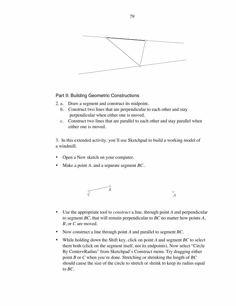
79
Part II: Building Geometric Constructions
2. a. Draw a segment and construct its midpoint.
b. Construct two lines that are perpendicular to each other and stay
perpendicular when either one is moved.
c. Construct two lines that are parallel to each other and stay parallel when
either one is moved.
3. In this extended activity, you’ll use Sketchpad to build a working model of
a windmill.
• Open a New sketch on your computer.
• Make a point A, and a separate segment BC.
C
B
A
• Use the appropriate tool to construct a line, through point A and perpendicular
to segment BC, that will remain perpendicular to BC no matter how points A,
B, or C are moved.
• Now construct a line through point A and parallel to segment BC.
• While holding down the Shift key, click on point A and segment BC to select
them both (click on the segment itself, not its endpoints). Now select “Circle
By Center+Radius” from Sketchpad’s Construct menu. Try dragging either
point B or C when you’re done. Stretching or shrinking the length of BC
should cause the size of the circle to stretch or shrink to keep its radius equal
to BC.

80
C
B
A
• Place points where the circle intersects the lines. Drag either point
B or C to make sure these points stay at the intersections.
• Draw segments from the center of the circle to each of the four intersection
points.
• Hide (don’t delete) the circle and lines. Don’t hide the segments. Your sketch
should look like this:
A
B
C
• Drag point B and observe what happens to the segments. Now select the
four points at the end of your “windmill.” Go under Sketchpad’s Display
menu and choose “Trace Points.” Drag point B again and observe the
paths traced by the four points. Try dragging point B slowly and tracing
your name.

81
APPENDIX C
THE ANALYSIS OF THE DYNAMIC
GEOMETRY INTERVIEW TAPES
The interviews conducted in our dynamic geometry study yielded 20 hours of
videotape data. This appendix describes the process involved in shaping the raw
footage into organized, thematic strands. Central to this task were two
considerations:
1. How should the videotape data be coded into a corresponding paper format?
In doing so, what level of detail should be extracted?
2. In deciding which mathematical episodes to include in this dissertation,
what criteria should be used to select “noteworthy” events?
The discussion that follows addresses these areas of concern. The appendix
concludes by contrasting my analysis technique to an alternative method proposed
by Schoenfeld (1985).
Transferring the Interviews Into Paper Format
At the heart of any interview study are the words spoken by interviewees.
Transcribing speech into written form provides the researcher with a convenient
medium for subsequent analysis. If words alone, however, are the only events
recorded, certain pieces of data are likely to be lost. These include pauses in
speech, tone of voice, and facial expressions.
The inadequacy of word-by-word transcriptions was particularly acute in our
interviews. Nearly all of the conversations between interviewer and interviewees
centered on the actions occurring on a computer screen. Typical of our written
transcripts was this line spoken by an interviewee: “You see, we need to move
point A. You see, over here…Oh, it’s X that does this…We’ve got this…And so
far, I can move this.”
Where, exactly is “here”? And what are we to make of the three references to
“this”?
From the start, I knew that bringing meaning to our interview transcripts
required a second level of transcription; one of a pictorial nature. As I viewed the
tapes, I needed a way to capture the geometric activity that accompanied our
interviewees’ words.
Practically speaking, I could not draw every image that appeared on screen.
Interviewees reconfigured their geometric constructions hundreds, perhaps
thousands, of times during the course of their interviews, whether it was dragging
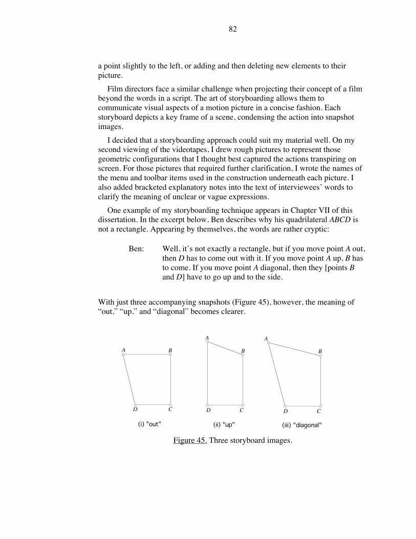
82
a point slightly to the left, or adding and then deleting new elements to their
picture.
Film directors face a similar challenge when projecting their concept of a film
beyond the words in a script. The art of storyboarding allows them to
communicate visual aspects of a motion picture in a concise fashion. Each
storyboard depicts a key frame of a scene, condensing the action into snapshot
images.
I decided that a storyboarding approach could suit my material well. On my
second viewing of the videotapes, I drew rough pictures to represent those
geometric configurations that I thought best captured the actions transpiring on
screen. For those pictures that required further clarification, I wrote the names of
the menu and toolbar items used in the construction underneath each picture. I
also added bracketed explanatory notes into the text of interviewees’ words to
clarify the meaning of unclear or vague expressions.
One example of my storyboarding technique appears in Chapter VII of this
dissertation. In the excerpt below, Ben describes why his quadrilateral ABCD is
not a rectangle. Appearing by themselves, the words are rather cryptic:
Ben: Well, it’s not exactly a rectangle, but if you move point A out,
then D has to come out with it. If you move point A up, B has
to come. If you move point A diagonal, then they [points B
and D] have to go up and to the side.
With just three accompanying snapshots (Figure 45), however, the meaning of
“out,” “up,” and “diagonal” becomes clearer.
D C
BA
D C
B
A
D C
B
A
(i) "out" (ii) "up" (iii) "diagonal"
Figure 45. Three storyboard images.

83
Shortcomings of a Storyboard Approach
If the storyboard method was to be effective (both for myself in analyzing the
data and for readers who could not view the actual tapes), I knew my transcripts
and storyboards would need to stand on their own as a meaningful account of the
interviews. With my hand-drawn sketches complete, I put the work aside and then
returned to the data with fresh eyes.
As I read the interviewees’ words and viewed my accompanying pictures, I
knew that on one level, the experiment was a success—I could reconstruct the
sequence of geometric actions that occurred during the course of the interview. At
the same time, though, I felt that something had been lost. The exact nature of this
loss remained unclear until I sat down to view the tapes again.
My storyboards presented freeze-frame views of the actions occurring
onscreen. In Storyboard #1, point A might be in the top right corner of the screen.
In Storyboard #2, the same point might now be in the lower left corner. How it
moved from one location to another was not indicated.
In many instances, the details behind this change of location were either
uninteresting or simple: point A moved from one corner to the other by being
dragged in a straight line. Yet sometimes, the movement involved was more
intriguing and could not be represented strictly through pictures. Just as tone of
voice could be a clue to one’s thoughts, so could, I realized, the speed and nature
of one’s mouse movements onscreen. Consider the passage below which is drawn
from Chapter VI of this dissertation.
Ben now returns to our pre-built isosceles triangle, TNJ. He begins to drag
point N. His mouse movements, slow and tentative at first, cause N to rock
back and forth along a small arc of the hidden circle. Point N vacillates in
this manner for approximately seven times, never spanning more than half
the entire circle’s arc.
David and the interviewer continue to talk while Ben stares at point N’s
movement. Soon Ben interjects, “OK, that’s a circle!” Once Ben
announces his discovery, he begins to move point N rapidly, now twirling
it around the entire circle. Ben spins the point again and again, as if to
confirm his statement.
Neither a picture of !TNJ nor Ben’s quotation (“OK, that’s a circle!) are enough
to appreciate Ben’s gradual uncovering of the hidden circle.
I decided on a case-by-case basis whether my storyboards and written
transcriptions required additional descriptive commentary. If the descriptions
became too long, I simply flagged the corresponding videotape excerpt as
something that I would need to watch rather than annotate.

84
The reader can find two of my annotated interview excerpts in
Appendix D.
What Counts as a Noteworthy Event?
With my descriptive coding complete, I began to consider a broad question:
How did interviewees perform on our black-box tasks? The answer to this
question depended on the lens I applied to the data. If I chose to focus on whether
interviewees knew the technicalities of each Sketchpad command and menu item,
there were plenty of minor mistakes to report. These included:
• Interviewees did not hold down the “Shift” key when trying to select
more than one object on screen.
• In trying to create points that traveled along lines, interviewees
mistakenly constructed the points before the lines.
From a software design perspective, such observations could be valuable
(indeed the newest version of Sketchpad eliminates the need for the “Shift” key
and for creating lines before points). But these findings seemed bland in light of
our study’s goal—to uncover those areas of students’ geometric thinking that
were shaped by the dynamic geometry software.
While much of our interviewees’ work was routine in nature, there were
excerpts of videotape—some spanning no more than a minute, others longer—
where interviewees performed a certain action or gave a verbal description that
clearly surprised the interviewer. These were places where interviewees’ ideas did
not fit either the “normal” approach or a predictable misstep (such as the bulleted
items above). Confrey (1991) describes the value of finding such occurrences:
Seldom are students’ responses careless or capricious. We must seek out
their systematic qualities which are typically grounded in the conceptions
of the student…Frequently when students’ responses deviate from our
expectations, they possess the seeds of alternative approaches which can
be compelling, historically supported and legitimate if we are willing to
challenge our assumptions…It is at points of contact, at moments of
discrepancy, that we have the highest probability of gaining insight into
another person’s perspective. (p. 122)
Readers of this dissertation will find that nearly all of the data excerpted
throughout this work fits the general criteria below:
• The interviewees’ work is unorthodox. While neglecting to hold
down the “Shift” key would not be a great surprise to anyone familiar
85
with the software, the methods employed by our interviewees were
not predictable prior to conducting the study.
• The interviewees’ work is clever. This is not to say their methods
were always productive (see in particular Chapter VII for Jonathan’s
problems with a magnet metaphor). But in all cases, interviewees
approached their constructions in entirely reasonable ways.
• The geometric ways of thinking involved are specific to dynamic
geometry software. Uncovering hidden paths (Chapter VI), describing
objects in terms of movement metaphors (Chapter VII), and finding
alternative ways to build a square (Chapter VIII) all depend on the
tools made available by the software.
In choosing examples that conformed to these criteria, my challenge, working
from Confrey’s perspective described above, was to chronicle the unforeseen and
sensible use of Sketchpad, as compared to its misuse.
This goal was aided by the style of our interviews. As interviewers with years
of experience using the software, we were comfortable enough with Sketchpad so
that interviewees’ tiny missteps did not bother us. We gave aid where appropriate
and did not dismiss ideas that others with less software knowledge might have
deemed unworkable.
Developing My Interpretations
At this stage in the analysis process, I knew which interview excerpts I would
develop into narratives. I envisioned each narrative as consisting of three parts.
First, I would describe for the reader the “normal” manner in which a particular
construction could be accomplished with Sketchpad. Then, I would offer an
interviewee’s method, highlighting the ways in which it differed from the norm.
Finally, I would analyze the interviewee’s work, attempting to uncover the merits
of her reasoning.
This entire interpretive process was shaped by an admonition of Confrey
(1993) similar to the one I quoted previously:
…when interpreting data, the interviewer must demonstrate his/her own
willingness to examine his/her own assumptions and challenge the validity
of those assumptions…one can come to see how frequently what is
labeled as student’s inadequacy is really the result of our own inflexibility
in considering alternative perspectives. (p. 6)
Chapter VIII of this dissertation provides an example of this approach. It would
have been easy to dismiss the work of Jonathan, Marcus, and Sam as incorrect
86
ways of building a square. Instead, I found aspects of their work that while
problematic, still displayed ingenuity.
Sharing My Interpretations
Having developed my own theories of interviewees’ motivations, I needed a
way to validate my findings. To gain feedback and alternative perspectives, I
requested the assistance of a fellow Mathematics Education Ph.D. student in New
York University’s Department of Teaching and Learning.
For our first few meetings together, I did not bring videotapes. Rather, I sat
with my colleague at a computer and introduced her to the features of Sketchpad.
When she developed some familiarity with the software, I presented her with the
various black-box items from our interviews and allowed her to explore and then
recreate them on her own.
At this stage, I was ready to share the videotapes. For each excerpt, I first
allowed my colleague to view the tapes without any interruption. However, in
places where she needed a brief clarifying comment, I paused or rewound the tape
to offer an explanation. I then assumed the role of interviewer as I asked my
colleague to analyze what she saw and heard on the tapes. The questions of most
interest to me in nearly all cases were, “What do you think interviewees are trying
to accomplish here? What ideas are guiding their exploration/construction? Do
their ideas seem reasonable?”
This interviewing process gave way to discussions in which I shared, defended,
and reworked my own interpretations of the video data. Through this
collaboration, I was able to provide support to my theories as well as consider
new possibilities and themes suggested by my colleague.
Soliciting Feedback from Authorities in the Field
In January of 2001, I returned to my former workplace, Education
Development Center, Inc. in Newton, Massachusetts, to share and discuss my
dissertation draft with my former research partner E. Paul Goldenberg. I also
forwarded my draft to William Finzer, another leading authority in the field of
dynamic geometry curriculum and research. The feedback that I received from
both individuals helped to confirm the reasonableness of my interpretations. In the
case of William Finzer, for example, he noted that although my descriptions of
square constructions provided a challenge to his categories of drawing,
underconstraint, and appropriate constraints (Chapter VIII), he felt my analysis
added some worthwhile nuances to the categories.
An Alternative Approach

87
One of the more detailed descriptions of interview analysis techniques appears
in Schoenfeld’s Mathematical Problem Solving (1985). It is instructive to
consider his approach as a means of highlighting where (and why) I pursued a
different course.
Similar to our dynamic geometry study, Schoenfeld’s interviews focus on
geometry, though of the paper-and-pencil variety. He, too, provides transcripts of
the sessions along with illustrative pictures. But there the similarity ends.
Schoenfeld’s interest lies in charting the cognitive strategies of students. For
these purposes, he describes six problem-solving categories: Read, Analyze,
Explore, Plan, Implement, and Verify. Each interview is “parsed” into a timeline
showing which category best describes an inerviewee’s behavior at any given
moment. Particular attention is paid to junctures where students switch from one
strategy to another.
With this coding, the larger scope and progression of a student’s work assume
priority over specific incidents:
At the risk of flogging a dead horse, I wish to stress that…matters of
detail…are virtually irrelevant. A coding scheme should highlight major
decisions. (p. 289)
Because the coding stays general in nature, Schoenfeld maintains that the
process of analyzing an interview can be remarkably standardized, even for those
without graduate training. He says, “A team of undergraduate coders can be
trained to parse the protocols with accuracy and reliability” (p. 315).
Schoenfeld’s broad coding allows him to address issues of metacognition—
specifically, “the overall quality of the students’ monitoring, assessing, and
executive decision making” (p. 310). Sometimes the quality can be low, leading
students on “wild goose chases” or to choosing “ill-chosen approaches” (p. 282).
There is a definite appeal to Schoenfeld’s analysis technique. It introduces
some of the reliability found in quantitative methods into qualitative work. It does
not force us to reconsider our own methods of solving mathematical problems.
I accept that Schoenfeld’s method may yield more uniformity than my
approach. But I also maintain that this technique overlooks as much as it finds. I
believe that small incidents do matter: perhaps Jonathan’s magnet description of
perpendicularity in Chapter VII is a “wild goose chase,” but it’s a delightful one
because his use of a movement metaphor tells us something about the software we
did not know before.

88
APPENDIX D
TWO ANNOTATED INTERVIEW EXCERPTS
The two extended interview excerpts below are both drawn from Chapter VII
of this dissertation. Each focuses on the theme of metaphor. In the first excerpt,
Lynne connects her mathematical description of a construction to her partner
Ellen’s slingshot metaphor. In the second excerpt, Norman analyzes a
perpendicular bisector construction that he finds magnet-like in its behavior.
Extended Excerpt One
L
V
D
122. INT So here is another one
[opens a black box
sketch].
L
VD
Moving V "closer into the center"
“D gets smaller” = D moves closer to
L and V [interesting…Lynne says the
point itself gets smaller—it doesn’t].
“it gets big” = the lengths of LD and
VD get longer while D moves away
from L and V.
123. LYNNE Should we experiment?
If you move V closer
into the center [pt. L], it
gets smaller, when you
move it outwards, the D
stretches more out, but
L stays put. And when
you move L into V, D
gets smaller. When you
move it outwards again,
it gets big. When you
move D, it just—
Ellen motions with her hand showing
the motion of a rubber band as it’s
pulled back and then released.
*METAPHOR!*
124. ELLEN It’s one of those
like…what do you call
them? Slingshots. You
throw a rubber band and
then it— 125. LYNNE That’s cool [drags L]. I
think that…Here, would
you [Ellen] like to play
with it? I have a
hypothesis. I like that

89
word now. Ever since
yesterday. 126. ELLEN This looks cool.
“everything goes around L” = L stays
in place while D and V move.
127. LYNNE Well, when you move
V, everything goes
around L. Ah, where is
it?…and when you
move L, everything
goes around V. And
when you move D, it
does a little slingshot
thing.
“D and V might be on a line segment”
= when D and V are far apart, it
doesn’t appear that the distance
between them is changing (it is—it’s
just hard to see). But when L and V
get closer together, Lynne realizes the
distance between D and V isn’t
constant. [Again, another example of
informal language. It’s also not
always easy to judge whether certain
segments are constant or variable in
length just by eyeing them.]
128. ELLEN Yes. I think that maybe,
actually …well, I
think…I think that
maybe…that’s strange.
Well, I was about to say
that D and V might be
on a line segment.
When they go like this,
they don’t move apart.
But when you move
them in and they go
closer. So it is not true. 129. INT Wait, say more about—
you said you tried
something. You said,
“Ooh, strange.” But
that meant it wasn’t like
what you were thinking.
But I didn’t know what
you were thinking.
Lynne demonstrates that the distance
between D and V isn’t always the
same.
130. LYNNE I was about to say—I
don’t believe this is
correct—but I was
about to say that I just
—when I was going like
that, I didn’t really see
the width between D
and L changing. I was
about to say they were
on a line segment. But
they do change when
you do move it in and
out. So I don’t think that
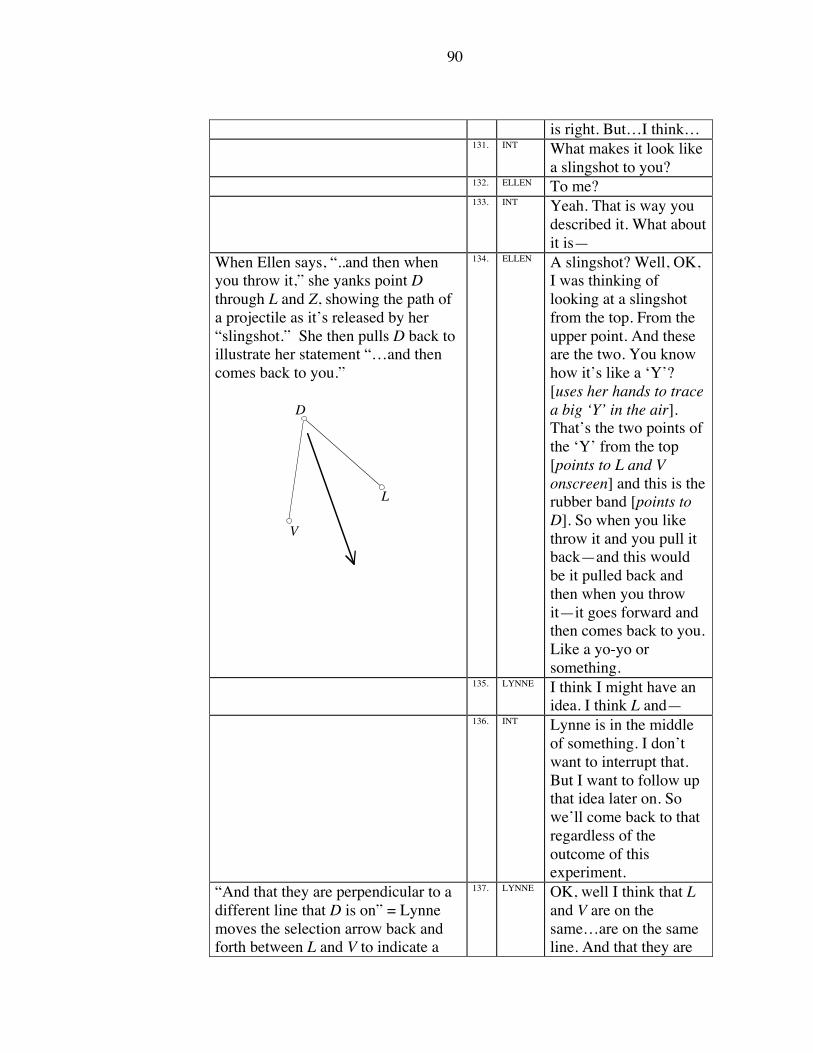
90
is right. But…I think… 131. INT What makes it look like
a slingshot to you? 132. ELLEN To me? 133. INT Yeah. That is way you
described it. What about
it is—
When Ellen says, “..and then when
you throw it,” she yanks point D
through L and Z, showing the path of
a projectile as it’s released by her
“slingshot.” She then pulls D back to
illustrate her statement “…and then
comes back to you.”
L
V
D
134. ELLEN A slingshot? Well, OK,
I was thinking of
looking at a slingshot
from the top. From the
upper point. And these
are the two. You know
how it’s like a ‘Y’?
[uses her hands to trace
a big ‘Y’ in the air].
That’s the two points of
the ‘Y’ from the top
[points to L and V
onscreen] and this is the
rubber band [points to
D]. So when you like
throw it and you pull it
back—and this would
be it pulled back and
then when you throw
it—it goes forward and
then comes back to you.
Like a yo-yo or
something. 135. LYNNE I think I might have an
idea. I think L and— 136. INT Lynne is in the middle
of something. I don’t
want to interrupt that.
But I want to follow up
that idea later on. So
we’ll come back to that
regardless of the
outcome of this
experiment.
“And that they are perpendicular to a
different line that D is on” = Lynne
moves the selection arrow back and
forth between L and V to indicate a
137. LYNNE OK, well I think that L
and V are on the
same…are on the same
line. And that they are

91
hidden segment. She then uses the
arrow to indicate a hidden line passing
through point D, perpendicular to LV.
“So that when you move…when you
move V up…” = Lynne shows that
when V is in a different position, the
same perpendicular relationship still
holds.
perpendicular to a
different line that D is
on. So that when you
move…when you move
V up, the line would be
going across through L
and V. And then if you
moved D like that,
another line would be
going through point D
and they would be
perpendicular. 138. INT Would you want to try
making a construction
like that somewhere to
see whether that works
that way? And first of
all, by the way, does
that make sense to you
[Ellen]? 139. ELLEN Well I got some of it.
There is going to be a
perpendicular line like
that and like that and
then there will be one
and then another against
each other sort of? 140. INT I was wondering
whether that… Yes, I
think that is what she
said. But I was actually
wondering whether that
fit—whether that
matched with your
picture of the slingshot.
As she was describing
that, can you fit that to
the picture that you
already had? 141. ELLEN Um…I think so. I mean
I don’t really know how
it’s like that. 142. INT Describe your thing
again [to Lynne]. You
see if you can, while she

92
is describing what she is
describing, you see if
you can picture your
slingshot. And see if the
things that she describes
fits that picture.
Because I’m curious.
You have one image,
you have another image.
They both are clearly
describing what each of
you are seeing. The
question is whether you
are seeing the same
thing.
When Lynne says, “I mean, when D is
passing through L and V like a
slingshot, it doesn’t go closer to L or
closer to V. It just stays in the center
of them both” she positions D like
this:
L
V
D
143. LYNNE Okay, well I think…It
looks…one of the
reasons it looks most
like a slingshot is
because it doesn’t curve
everywhere. It just stays
in the same straight
path, D does, when it is
going through L and V
[drags D back and
forth]. I mean, when D
is passing through L and
V like a slingshot, it
doesn’t go closer to L or
closer to V. It just stays
in the center of them
both.
Lynne shows that regardless of the
location of L and V, the path of point
D is always perpendicular to the
hidden segment LV.
LYNNE So I think that it would
make sense if D was on
a straight line going
through L and V. And L
and V…and if a straight
line was going through
D, and a straight line
was going through L
and V, it would make
sense because
everywhere, if you
could imagine the
straight lines there,

93
they’d always be
perpendicular. And so
could I try constructing
it? 144. INT Sure. Do you see the
slingshot in her
description? [Ellen
nods] Yeah. So near as
you can tell anyway,
until she constructs it, it
fits your picture…Sure,
give it a construction.
Extended Excerpt Two
*METAPHOR!*
A
B
“How does it keep away from the
line?” = when Norman drags A away
from B, the line follows A, but does
not ever reach it.
6. NRMN That’s weird. How does
it do that? How does it
[pt. A] keep away from
the line? It’s like a
magnet to the line.
“As I get it closer…” = when Norman
drags A towards B, the line moves
away from A, closer to B.
AB = the points
"coming together"
Notice how Norman emphasizes the
word “really”—he seems invested in
NRMN As I get it [pt. A] closer,
the line moves farther
away. And if I really try
hard, I can get them to
come together in the
center [drags pt. A onto
pt. B]…But how does it
do that?

94
the magnet metaphor. 7. INT Well, describe the ‘that’
again. What’s what?
You’re getting the—
“why won’t the dot just go right to the
line..” = point A causes the line to
move; the line doesn’t stay still
allowing the “dot” to reach it. The two
are connected and move in unison.
informal language: point = “dot”
8. NRMN Well, how does it—why
won’t the dot just go
right to the line rather
than take a while to—
why does the line move
back? [when pt. A is
dragged away from pt.
B] 9. INT Aha, what is the line
doing as you’re moving
this back? 10. NRMN Yeah. 11. INT What is the line doing
as you’re moving it
back? 12. NRMN It’s moving away from
the dot. 13. INT Is that true for both
dots?
Norman now drags point B and shows
that it, too, causes the same behavior
as point A. Note that point A is now
stationary.
14. NRMN Yeah. See, look. It
moves away.
15. INT What if you move the
dot away from the line?
Norman shows that if he drags point
B, then point A (the “other dot”) is a
“pressure point”—i.e., only when
point B rests directly on top of point A
do the points and the line all coincide.
16. NRMN The line follows it.
And, like, this [pt. A]
seems to be the pressure
point where the other—
where the other dot is, it
seems to be the place
where the dot— you
can’t touch the line, but
only there can the dot
touch the line; only
where the other dot is
can the dot touch the
line. 17. INT So now describe the line
in relation to the two
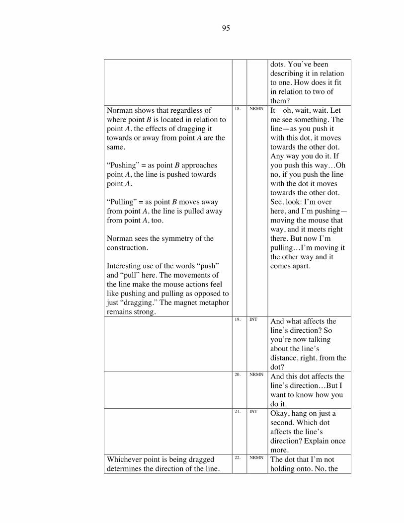
95
dots. You’ve been
describing it in relation
to one. How does it fit
in relation to two of
them?
Norman shows that regardless of
where point B is located in relation to
point A, the effects of dragging it
towards or away from point A are the
same.
“Pushing” = as point B approaches
point A, the line is pushed towards
point A.
“Pulling” = as point B moves away
from point A, the line is pulled away
from point A, too.
Norman sees the symmetry of the
construction.
Interesting use of the words “push”
and “pull” here. The movements of
the line make the mouse actions feel
like pushing and pulling as opposed to
just “dragging.” The magnet metaphor
remains strong.
18. NRMN It—oh, wait, wait. Let
me see something. The
line—as you push it
with this dot, it moves
towards the other dot.
Any way you do it. If
you push this way…Oh
no, if you push the line
with the dot it moves
towards the other dot.
See, look: I’m over
here, and I’m pushing—
moving the mouse that
way, and it meets right
there. But now I’m
pulling…I’m moving it
the other way and it
comes apart.
19. INT And what affects the
line’s direction? So
you’re now talking
about the line’s
distance, right, from the
dot? 20. NRMN And this dot affects the
line’s direction…But I
want to know how you
do it. 21. INT Okay, hang on just a
second. Which dot
affects the line’s
direction? Explain once
more.
Whichever point is being dragged
determines the direction of the line.
22. NRMN The dot that I’m not
holding onto. No, the

96
dot that I am holding
onto.
APPENDIX E
CONSTRUCTION VARIATIONS
Two recommendations in Chapter IX suggest testing alternative
constructions of the square and isosceles triangle. Below are step-by-step
instructions for building these objects.
The Square (see Figure 46)
1. Draw a circle with center, A, and control point B.
2. Construct a diameter BC through points A and B.
3. Construct a diameter DE perpendicular to
!
BC through point A.
4. Connect C, E, B, and D to form a square.
5. Hide point A, the two diameters, and the circle.
6. Drag point B to expand and shrink the square.
A
B
C
A
B
C
D
E
Figure 46. Constructing square CEBD.

97
The Isosceles Triangle (see Figure 47)
1. Draw a circle with center, A, and control point B.
2. Place a random point C on the circle’s circumference. Connect A, B, and C
to form isosceles triangle ABC.
3. Hide the circle.
4. Place a random point D on
!
AB . Construct segment DE parallel to
!
BC .
5. Hide
!
AB ,
!
BC , and
!
AC . Connect A to D and A to E to form isosceles
triangle ADE.
6. Drag point A or D to expand and shrink the triangle.
A
B C
A
B C
D E
Figure 47. Constructing isosceles triangle ADE.