spl port hedland boodarie strategic industrial area
TRANSCRIPT
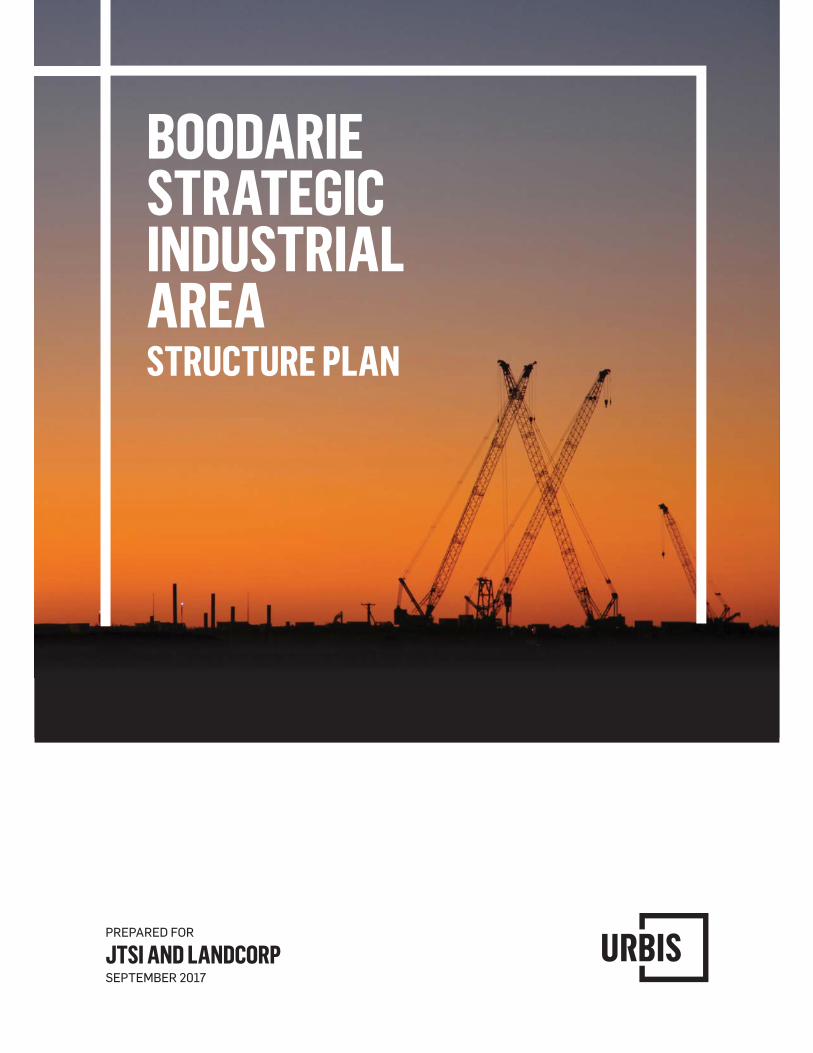
BOODARIE STRATEGIC INDUSTRIAL AREASTRUCTURE PLAN
PREPARED FOR
JTSI AND LANDCORPSEPTEMBER 2017

URBIS STAFF RESPONSIBLE FOR THIS REPORT WERE:
Director Karen Wright Associate Director Sally Birkhead Consultant Stephanie Norgaard Project Code PA0929 Report Number V5 FINAL

Schedule of Amendments
Amendment No. Summary of the Amendment
Amendment Type Date Approved by WAPC
EXECUTIVE SUMMARY The Boodarie Strategic Industrial Area (BSIA) is located approximately 10km south west of Port Hedland in WA’s Pilbara Region.
The BSIA Structure Plan provides for the nationally significant, long term strategic industrial development of the area. It will coordinate the detailed land use and development of the BSIA, including the provision of proponent funded services and infrastructure.
The structure plan ensures that the State and National drive for diversified industry has been recognised and maintained, whilst balancing the needs of industrial users, along with a focus on the sustainability of the local community.
To facilitate the effective functioning of the BSIA, strategic infrastructure corridors are identified, connecting the BSIA to the Port of Port Hedland. The BSIA is positioned to accommodate strategic downstream resource processing industries related to the ore and petro-gas resources of the Pilbara region.
Development of land in the Boodarie Strategic Industrial Area under the control of the Pilbara Ports Authority (PPA) (which is under the Port Authorities Act 1999) or held as a Reserve under the Land Administration Act 1997) including part of the proposed infrastructure corridor, requires the approval of the PPA.
The proximity of the Port to the BSIA has the potential to create a world-class heavy industrial estate which specialises in multi-product, downstream resource processing.
STRUCTURE PLAN OBJECTIVES The objectives of the BSIA Structure Plan are as follows:
Provide a framework to guide coordinated development of the BSIA and future planning approvals in order to optimise capacity for strategic industrial use.
Provide industry with a comprehensive information pack, in the form of this structure plan and associated reports, to facilitate appropriate types and forms of development within the BSIA.
Establish specific infrastructure corridors that provide an essential link between the Port and the BSIA.
Establish Port capacity and access to enable optimal industrial development and export within the BSIA.
Facilitate development through the Town of Port Hedland Town Planning Scheme No.5 (TPS5) and a structure plan process consistent with the WAPC’s Structure Plan Framework; and
Recognise the governance structure for the implementation of the structure plan.
STATUTORY SUPPORT The BSIA is zoned ‘Strategic Industry’ under the Town of Port Hedland’s Town Planning Scheme 5 (TPS5), requiring comprehensive planning prior to the commencement of industrial development. The structure plan reinforces and elaborates on the intent, objectives and planning requirements for the BSIA.
INDUSTRIAL SEPARATION The structure plan, and in particular the identification of precincts and preferred land uses, has been prepared based on the outcomes of a series of relevant emission assessments including acoustic, quantitative risk, and air quality assessments.
Externally, the protection of the BSIA from incompatible uses, or proximity to sensitive uses is provided for by the Boodarie Industrial Buffer Special Control Area (SCA).
INDUSTRIAL ECOLOGY The industrial ecology input and output assessment provides the foundation for utility demand forecasting, and assists in identifying industrial synergy opportunities for the BSIA. The input and output assessment has implications for industrial land use placement, relationship to infrastructure corridors, and transport connections.
Industry clustering is a critical element to allow for the development of synergies within the BSIA and the surrounding region, as well as a mechanism to optimise utility infrastructure and associated costs. Industry clustering is facilitated through the designation of industry precincts and the placement of associated industries within them.
INDUSTRIAL DESIGN CONSIDERATIONS The success of the BSIA largely depends on providing for industry operational requirements and efficient access to the Port. This in turn requires a carefully considered layout of infrastructure corridors.
The preparation of the BSIA Structure Plan was based on a set of criteria including:
An estimation of industries’ requirements relative to central infrastructure corridor access. Infrastructure corridor componentry. Port capacity. Proximity to Port. Industrial synergies. Industrial layout and separation requirements.
The design of the BSIA has been developed with consideration to the above criteria, and tested against the emission assessments, to ensure it is appropriate for the anticipated industrial uses. A summary of this information is provided on the BSIA Opportunities and Constraints Plan (refer Figure 7).
Key consideration was also given to achieving integration between the Port Hedland Port Authority Multi User Outer Harbour Port Master Plan, the Inner Harbour and development proposed within the BSIA. To this extent, Worley Parsons was engaged to consider the interface between the Port Master Plan and the BSIA Structure Plan; identifying requisite development and design outcomes.
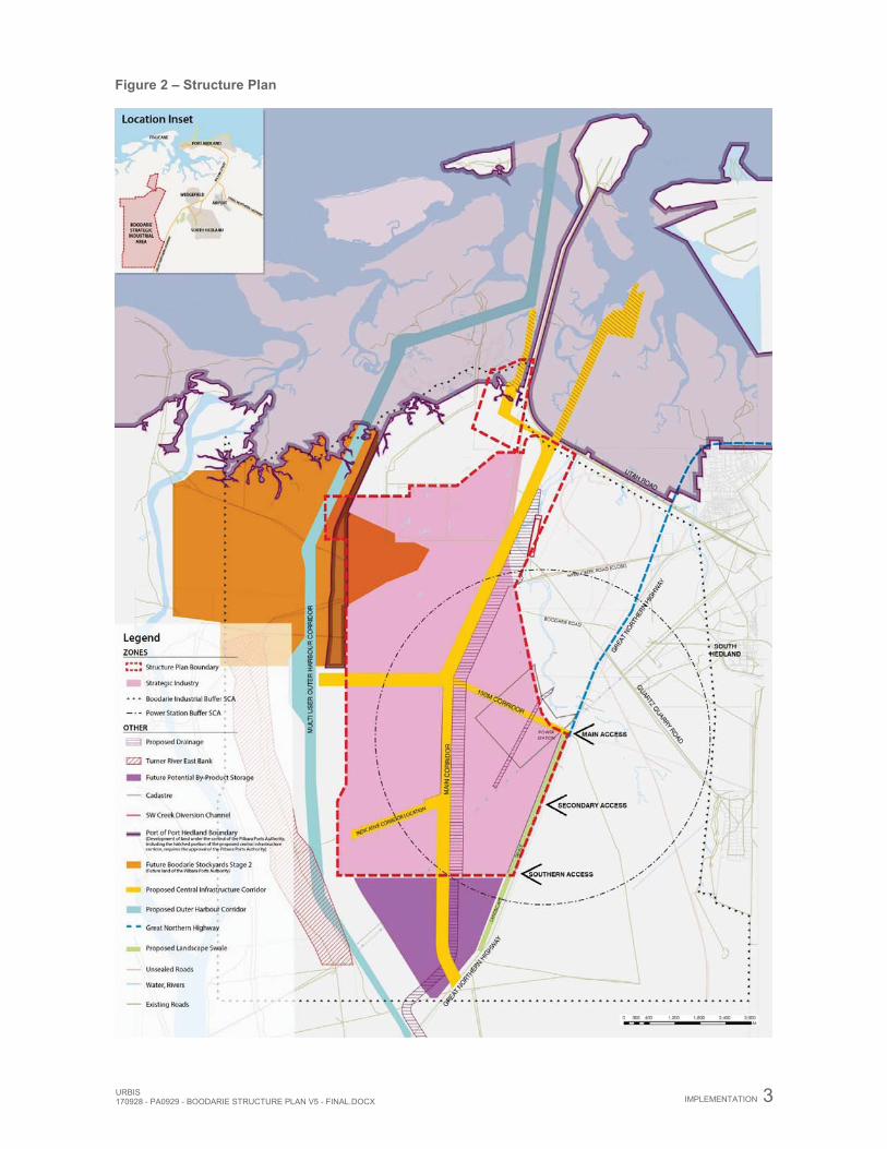
The BSIA Structure Plan (Figure 2), incorporates a site responsive approach which provides for the development of diversified industry through providing flexibility for industrial operational needs, whilst taking into account environmental considerations.
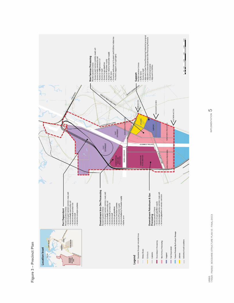
The structure plan and supporting precinct plan (Figure 3) are intended to guide the location of land uses within the BSIA. As industries locate over time, the Precincts can be reassessed. If an industrial developer demonstrates as part of its business case that it should be located in an alternative location to the preferred precinct, favourable consideration may be given, subject to business case approval by the Department of Jobs Tourism Science and Innovation (JTSI) and LandCorp.
DEVELOPMENT IMPLEMENTATION AND GOVERNANCE JTSI is the Lead Agency for the BSIA with the ongoing management of the BSIA undertaken by LandCorp.
The development of the BSIA is to be proponent driven as guided by JTSI and LandCorp. Proponents are therefore responsible for the construction of all infrastructure required to service their sites. Where necessary, this infrastructure may extend beyond its own landholding. The benefits associated with shared services are acknowledged and LandCorp and JTSI will require that the proponent’s servicing strategy investigate the opportunity for the construction of shared services to benefit the whole of the BSIA.
LandCorp will hold tenure of the BSIA, and land will be leased to proponents. When considering Business Case submissions from industry proponents seeking to establish within the BSIA the JTSI and LandCorp will consider the proposal in the context of the Structure Plan, the supporting technical reports and operational requirements of the BSIA.
Prior to lodgement of proponents’ planning application for consideration by the Town of Port Hedland, or undertaking works, it is a requirement that proposals be endorsed by JTSI and LandCorp.
Development of land in the Boodarie Strategic Industrial Area that is vested in the PPA under the Port Authorities Act 1999, including part of the proposed Infrastructure Corridor, requires the approval of the PPA.
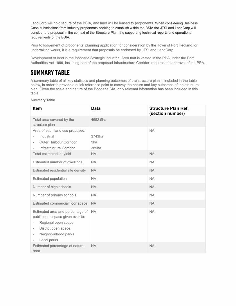
SUMMARY TABLE A summary table of all key statistics and planning outcomes of the structure plan is included in the table below, in order to provide a quick reference point to convey the nature and key outcomes of the structure plan. Given the scale and nature of the Boodarie SIA, only relevant information has been included in this table.
Summary Table
Item Data Structure Plan Ref. (section number)
Total area covered by the structure plan
4652.5ha
Area of each land use proposed: - Industrial - Outer Harbour Corridor - Infrastructure Corridor
3743ha 9ha 389ha
NA
Total estimated lot yield NA NA
Estimated number of dwellings NA NA
Estimated residential site density NA NA
Estimated population NA NA
Number of high schools NA NA
Number of primary schools NA NA
Estimated commercial floor space NA NA
Estimated area and percentage of public open space given over to: - Regional open space - District open space - Neighbourhood parks - Local parks
NA NA
Estimated percentage of natural area
NA NA
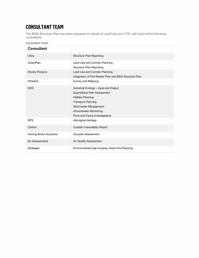
CONSULTANT TEAM The BSIA Structure Plan has been prepared on behalf of LandCorp and JTSI, with input of the following consultants:
Consultant Team
Consultant
Urbis Structure Plan Reporting
UrbanPlan Land Use and Corridor Planning
Structure Plan Reporting
Worley Parsons Land Use and Corridor Planning
Integration of Port Master Plan and BSIA Structure Plan
Whelans Survey and Mapping
GHD Industrial Ecology – Input and Output
Quantitative Risk Assessment
Utilities Planning
Transport Planning
Stormwater Management
Groundwater Monitoring
Flora and Fauna Investigations
RPS Aboriginal Heritage
Cardno Coastal Vulnerability Report
Herring Storer Acoustics Acoustic Assessment
Air Assessments Air Quality Assessment
Strategen Environmental Gap Analysis, Bush Fire Planning
URBIS 170928 - PA0929 - BOODARIE STRUCTURE PLAN V5 - FINAL.DOCX
TABLE OF CONTENTS
1. Implementation ..................................................................................................................................... 1 1.1. Structure Plan Area ............................................................................................................................... 1 1.2. Structure Plan Objectives ..................................................................................................................... 1 1.3. Structure Plan Content.......................................................................................................................... 1 1.4. Operation .............................................................................................................................................. 1 1.5. Subdivision and Development Requirements ....................................................................................... 4 1.5.1. Subdivision Principles ........................................................................................................................... 4 1.5.2. Land Use and Development ................................................................................................................. 4 1.6. Additional Information ........................................................................................................................... 6 2. Explanatory Section .............................................................................................................................. 8 2.1. Planning Background ............................................................................................................................ 8 2.2. Introduction and Purpose ...................................................................................................................... 8 2.3. Purpose of Strategic Industrial Areas ................................................................................................... 8 2.3.1. Background to Structure Plan ............................................................................................................... 8 2.3.2. Consultation .......................................................................................................................................... 9 2.4. Land Description ................................................................................................................................. 10 2.4.1. Location .............................................................................................................................................. 10 2.4.2. Area and Use ...................................................................................................................................... 10 2.4.3. Legal Description and Ownership ....................................................................................................... 10 2.5. Planning Framework ........................................................................................................................... 10 2.5.1. Zoning and Reservations .................................................................................................................... 10 2.5.2. Planning Strategies ............................................................................................................................. 13 2.5.3. Planning Strategies ............................................................................................................................. 14 2.5.4. Other Approvals and Decisions .......................................................................................................... 16 2.6. Implementation Structure .................................................................................................................... 16 2.6.1. Governance Structure ......................................................................................................................... 16 2.6.2. Lease and Development of Lots ......................................................................................................... 17 2.6.3. Developer Funding .............................................................................................................................. 17 2.6.4. Time Management – PAM Reserve .................................................................................................... 17 2.6.5. Integration with Port Hedland Port ...................................................................................................... 17 2.7. Precinct Requirements........................................................................................................................ 18 3. Site Conditions and Constraints ......................................................................................................... 19 3.1. Biodiversity and Natural Area Assets ................................................................................................. 19 3.1.1. Vegetation Description ........................................................................................................................ 19 3.1.2. Vegetation Extent Type and Status .................................................................................................... 19 3.1.3. Vegetation Condition........................................................................................................................... 19 3.1.4. Threatened Ecological Communities .................................................................................................. 20 3.1.5. Flora Species ...................................................................................................................................... 20 3.1.6. Significant Flora Species .................................................................................................................... 20 3.1.7. Introduced Flora .................................................................................................................................. 20 3.1.8. Mulgara Fauna .................................................................................................................................... 20 3.2. Landform and Soils ............................................................................................................................. 20 3.2.1. Land Systems ..................................................................................................................................... 20 3.2.2. Geology ............................................................................................................................................... 21 3.2.3. Soils .................................................................................................................................................... 21 3.2.4. Geotechnical Analysis......................................................................................................................... 21
URBIS170928 - PA0929 - BOODARIE STRUCTURE PLAN V5 - FINAL.DOCX
3.2.5. Acid Sulphate Soils ............................................................................................................................. 22 3.3. Groundwater and Surface Water ........................................................................................................ 23 3.4. Bushfire Hazard .................................................................................................................................. 26 3.5. Heritage .............................................................................................................................................. 27 3.5.1. Native Title .......................................................................................................................................... 27 3.5.2. Heritage Survey .................................................................................................................................. 27 3.5.3. Aboriginal Site Identification ............................................................................................................... 27 3.5.4. Archaeological Sites ........................................................................................................................... 28 3.5.5. Ethnographic Survey........................................................................................................................... 28 3.6. Context and other Land Use Constraints and Opportunities .............................................................. 28 4. Design Philosophy, Land Use and Subdivision/Development Requirements .................................... 31 4.1. Boodarie Strategic Industrial Area – Structure Plan ........................................................................... 31 4.1.1. Vision .................................................................................................................................................. 31 4.1.2. Objectives ........................................................................................................................................... 31 4.1.3. Overview ............................................................................................................................................. 31 4.2. Spatial Land Use Considerations ....................................................................................................... 32 4.2.1. Industrial Ecology ................................................................................................................................ 32 4.2.2. Utility Demand Forecasting ................................................................................................................. 32 4.2.3. Centralised Water, Energy, By-Product Facilities ............................................................................... 32 4.2.4. Centralised Industry Feedwater Facility .............................................................................................. 32 4.2.5. Centralised Energy Facility ................................................................................................................. 33 4.2.6. Centralised By-Product Facility ........................................................................................................... 33 4.2.7. Precincts and Industry Clustering ....................................................................................................... 33 4.3. Infrastructure and Corridor Considerations......................................................................................... 33 4.3.1. Industry Association to Port ................................................................................................................ 33 4.3.2. Compatibility of Industry, Staging and Perceived Port Facility Needs ................................................ 34 4.3.3. Infrastructure Corridors and Componentry ......................................................................................... 35 4.3.4. Shipping Tonnages ............................................................................................................................. 37 4.3.5. Direct Port Access .............................................................................................................................. 37 4.4. Industrial Separation ........................................................................................................................... 38 4.4.1. Acoustic Assessment .......................................................................................................................... 38 4.4.2. Air Quality Assessment ....................................................................................................................... 38 4.4.3. Quantitative Risk Assessment ............................................................................................................ 39 4.4.4. Spatial Land Use Considerations Summary ....................................................................................... 39 4.5. Design Elements ................................................................................................................................. 40 4.6. Estate Design ...................................................................................................................................... 41 4.7. Proposed Precincts ............................................................................................................................. 42 4.8. Common Infrastructure ....................................................................................................................... 42 4.9. Port Capacity and Access ................................................................................................................... 45 4.10. Movement Network ............................................................................................................................. 46 4.10.1. Traffic Generation ............................................................................................................................... 46 4.10.2. Forecast Traffic Volumes at Intersections with GNH .......................................................................... 46 4.10.3. Internal Roads and Intersection Controls ........................................................................................... 46 4.10.4. Great Northern Highway ..................................................................................................................... 49 4.10.5. GNH Intersection Analysis .................................................................................................................. 49 4.10.6. Interim Development ........................................................................................................................... 49 4.10.7. Austroads Intersection Treatment ....................................................................................................... 50 4.10.8. Off and On Road Parking ................................................................................................................... 50 4.10.9. High Wide Loads (HWL) ..................................................................................................................... 50
URBIS 170928 - PA0929 - BOODARIE STRUCTURE PLAN V5 - FINAL.DOCX
4.11. Utilities ................................................................................................................................................ 50 4.11.1. Infrastructure Capacity ........................................................................................................................ 50 4.11.2. Communications ................................................................................................................................. 52 4.11.3. Power .................................................................................................................................................. 52 4.11.4. Water Supply ...................................................................................................................................... 52 4.11.5. Gas Supply ......................................................................................................................................... 53 4.11.6. Priority Basic Raw Materials and Key Extraction Areas ..................................................................... 53 5. Technical Studies Appendices Index .................................................................................................. 54 TECHNICAL APPENDICES ............................................................................................................................ 56 GENERAL APPENDICES ............................................................................................................................... 57 Appendix A BSIA Land Tenure and Interests ............................................................................................ 58 Appendix B Aboriginal Heritage ................................................................................................................. 59 Appendix C Pilbara Ports Authority – Berth Placement ............................................................................. 60 Appendix D BHP Billiton Amended Loop Corridor ..................................................................................... 61 Appendix E Stakeholder Consultation ....................................................................................................... 62 Appendix F Department of Water and Environmental Regulation Approval ............................................. 67 Appendix G Draft Subdivision Conditions .................................................................................................. 68 Appendix H RUIC Limited Bush Fire Management Plan ........................................................................... 70 Appendix I WAPC ref: 153431 – Plan of Subdivision and Subdivision Approval ..................................... 71 Appendix J DWER Approval to DWMS ..................................................................................................... 72 Appendix K Summary of Submissions ....................................................................................................... 73 Appendix L Gazettal Notice – Amendment 71 .......................................................................................... 74 EXTERNAL REPORT APPENDICES ............................................................................................................. 75 Appendix I: Current Land Use and Interests Report ....................................................................................... 76 Appendix II: GHD BSIA Traffic Report ............................................................................................................. 77 Appendix III: GHD BSIA District Water Management Strategy ....................................................................... 78 Appendix IV: GHD BSIA Geotechnical Report ................................................................................................ 79 Appendix V: GHD BSIA Flora and Fauna Assessment ................................................................................... 80 Appendix VI: GHD Groundwater Monitoring.................................................................................................... 81 Appendix VII: GHD Turner River Flood Study ................................................................................................. 82 Appendix VIII: RPS Aboriginal Heritage Assessment ..................................................................................... 83 Appendix IX: GHD BSIA Industrial Ecology Strategy ...................................................................................... 84 Appendix X: Herring Storer Acoustic BSIA Environmental Noise Assessment ............................................... 85 Appendix XI: Air Assessments Air Quality Assessment .................................................................................. 86 Appendix XII: GHD BSIA Concept Plan for Quantitative Risk Assessment .................................................... 87 Appendix XIII: Worley Parsons Technical Note ............................................................................................... 88 Appendix XIV: Cardno Coastal Vulnerability Report ....................................................................................... 89 Appendix XV: Strategen Bush Fire Assessment ............................................................................................. 90
URBIS170928 - PA0929 - BOODARIE STRUCTURE PLAN V5 - FINAL.DOCX
FIGURES: Figure 1 – Location Plan .................................................................................................................................. 2 Figure 2 – Structure Plan ................................................................................................................................. 3 Figure 3 – Precinct Plan ................................................................................................................................... 5 Figure 4 – Scheme Zoning ............................................................................................................................. 11 Figure 5 – Pilbara Port City Growth Plan ..................................................................................................... 15 Figure 6 – Opportunities and Constraints Plan ........................................................................................... 30 Figure 7 – Central Infrastructure Corridor Cross Section .......................................................................... 44 Figure 8 – Movement Network ....................................................................................................................... 48 Figure 9 – Utilities ........................................................................................................................................... 51
TABLES: Table 1 – Requirements for Applications for Subdivision Approval ........................................................... 6 Table 2 – BSIA Material and Service Inputs ................................................................................................. 32 Table 3 – BSIA Key Indicative Outputs ......................................................................................................... 32 Table 4 – Relationship of Industries to Port ................................................................................................ 34 Table 5 – Infrastructure Corridors Component Summary .......................................................................... 36 Table 6 – Industrial Layout Summary ........................................................................................................... 40 Table 7 – Summary of Industry by Precinct ................................................................................................. 42 Table 8 – Technical Studies Appendices Index ........................................................................................... 54
URBIS 170928 - PA0929 - BOODARIE STRUCTURE PLAN V5 - FINAL.DOCX
IMPLEMENTATION 1
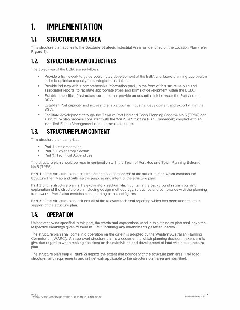
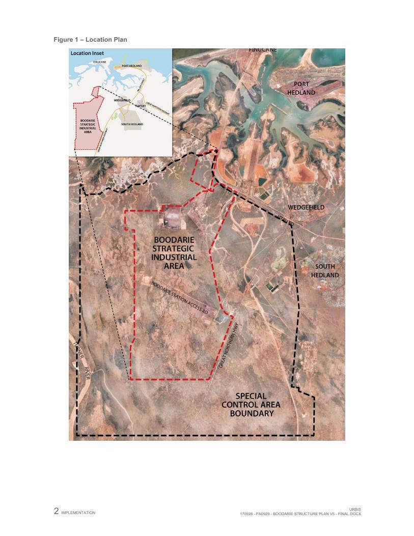
1. IMPLEMENTATION 1.1. STRUCTURE PLAN AREA This structure plan applies to the Boodarie Strategic Industrial Area, as identified on the Location Plan (refer Figure 1).
1.2. STRUCTURE PLAN OBJECTIVES The objectives of the BSIA are as follows:
Provide a framework to guide coordinated development of the BSIA and future planning approvals in order to optimise capacity for strategic industrial use.
Provide industry with a comprehensive information pack, in the form of this structure plan and associated reports, to facilitate appropriate types and forms of development within the BSIA.
Establish specific infrastructure corridors that provide an essential link between the Port and the BSIA.
Establish Port capacity and access to enable optimal industrial development and export within the BSIA.
Facilitate development through the Town of Port Hedland Town Planning Scheme No.5 (TPS5) and a structure plan process consistent with the WAPC’s Structure Plan Framework; coupled with an identified Estate Management and approvals structure.
1.3. STRUCTURE PLAN CONTENT This structure plan comprises:
Part 1: Implementation Part 2: Explanatory Section Part 3: Technical Appendices
The structure plan should be read in conjunction with the Town of Port Hedland Town Planning Scheme No.5 (TPS5).
Part 1 of this structure plan is the implementation component of the structure plan which contains the Structure Plan Map and outlines the purpose and intent of the structure plan.
Part 2 of this structure plan is the explanatory section which contains the background information and explanation of the structure plan including design methodology, relevance and compliance with the planning framework. Part 2 also contains all supporting plans and figures.
Part 3 of this structure plan includes all of the relevant technical reporting which has been undertaken in support of the structure plan.
1.4. OPERATION Unless otherwise specified in this part, the words and expressions used in this structure plan shall have the respective meanings given to them in TPS5 including any amendments gazetted thereto.
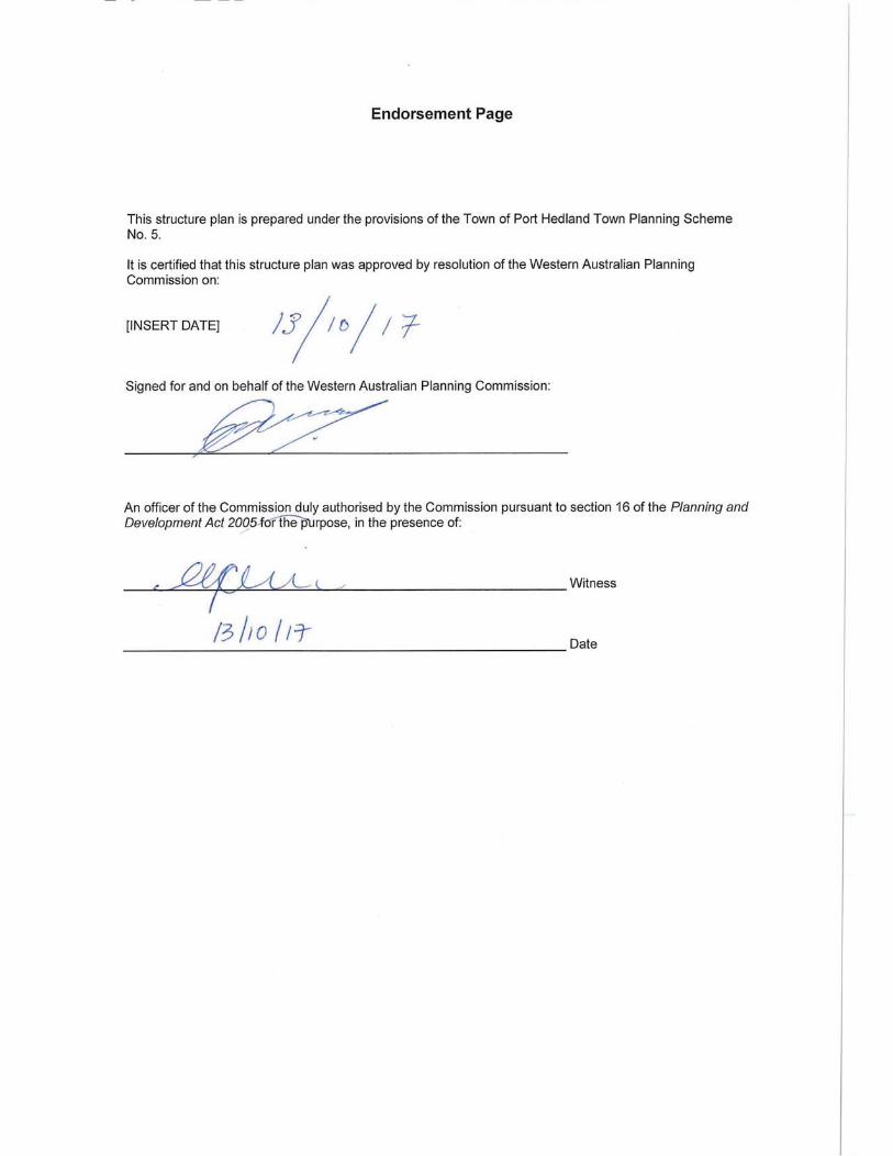
The structure plan shall come into operation on the date it is adopted by the Western Australian Planning Commission (WAPC). An approved structure plan is a document to which planning decision makers are to give due regard to when making decisions on the subdivision and development of land within the structure plan.
The structure plan map (Figure 2) depicts the extent and boundary of the structure plan area. The road structure, land requirements and rail network applicable to the structure plan area are identified.
2 IMPLEMENTATION URBIS170928 - PA0929 - BOODARIE STRUCTURE PLAN V5 - FINAL.DOCX
Figure 1 – Location Plan
URBIS 170928 - PA0929 - BOODARIE STRUCTURE PLAN V5 - FINAL.DOCX
IMPLEMENTATION 3
Figure 2 – Structure Plan
4 IMPLEMENTATION URBIS170928 - PA0929 - BOODARIE STRUCTURE PLAN V5 - FINAL.DOCX
1.5. SUBDIVISION AND DEVELOPMENT REQUIREMENTS 1.5.1. Subdivision Principles
i. The nature of the BSIA development and servicing requirements of particular future industries means that conventional reticulated servicing requirements may not be applicable in all circumstances. As proponents requirements can vary considerably between projects and from one site to another, the types and methods of service provision should be considered on a case-by-case basis. Where proposals require services to be extended to the site, this should be undertaken in a coordinated way with the rest of the BSIA.
ii. Within the BSIA, proponents will be required to investigate, fund and implement the specific infrastructure and services they require for their developments (eg. power, water, telecoms and wastewater solutions).
1.5.2. Land Use and Development i. The structure plan applies to the area zoned ‘Strategic Industry’ and ‘Other Public Purposes’
(Port Facilities and Infrastructure) pursuant to the Town of Port Hedland TPS5. ii. Development within the structure plan shall be consistent with the prescribed zonings and
reservations as detailed on the structure plan map as reflected in Figure 2, and as defined under TPS5.
iii. Land use permissibility is to be in accordance with the relevant zone as set out in the Zoning Table and section 7.2 of TPS5.
iv. As proponents’ development requirements can vary considerably based on the type of industry, associated operational requirements and site specific characteristics, the imposition of generic Development Approval conditions will not always be appropriate and may not reflect the flexibility required in the BSIA. Conditions of development approval should be considered on a case-by-case basis and have due regard to the objectives and provisions of the structure plan, including to Table 1.
v. Proponents are responsible for meeting the requirements of other State and Federal legislation that are applicable to the development application and proposal. This includes, but is not limited to, the requirements of the Environmental Protection Act 1986 (EP Act) and/or Environment Protection and Biodiversity Conservation Act 1999 (EPBC Act).
vi. Development of land in the Boodarie Strategic Industrial Area that is under the control of the PPA (which is under the Port Authorities Act 1999, or held as a Reserve under the Land Administration Act 1997) including part of the proposed Infrastructure Corridor, requires the approval of the PPA.
UR
BIS
17
0928
- PA
0929
- BO
OD
ARIE
STR
UC
TUR
E PL
AN V
5 - F
INAL
.DO
CX
IMPL
EM
ENTA
TIO
N 5
Figu
re 3
– P
reci
nct P
lan
6 IMPLEMENTATION URBIS170928 - PA0929 - BOODARIE STRUCTURE PLAN V5 - FINAL.DOCX
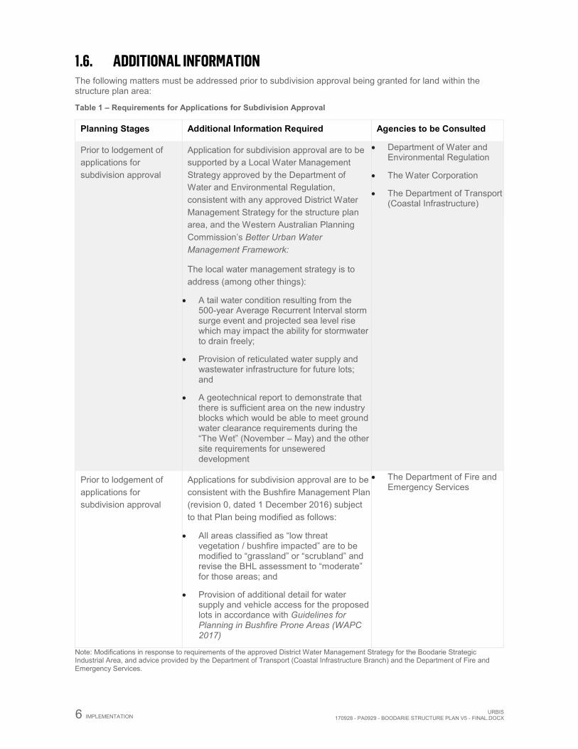
1.6. ADDITIONAL INFORMATION The following matters must be addressed prior to subdivision approval being granted for land within the structure plan area:
Table 1 – Requirements for Applications for Subdivision Approval
Planning Stages Additional Information Required Agencies to be Consulted
Prior to lodgement of applications for subdivision approval
Application for subdivision approval are to be supported by a Local Water Management Strategy approved by the Department of Water and Environmental Regulation, consistent with any approved District Water Management Strategy for the structure plan area, and the Western Australian Planning Commission’s Better Urban Water Management Framework:
The local water management strategy is to address (among other things):
A tail water condition resulting from the 500-year Average Recurrent Interval storm surge event and projected sea level rise which may impact the ability for stormwater to drain freely;
Provision of reticulated water supply and wastewater infrastructure for future lots; and
A geotechnical report to demonstrate that there is sufficient area on the new industry blocks which would be able to meet ground water clearance requirements during the “The Wet” (November – May) and the other site requirements for unsewered development
Department of Water and Environmental Regulation
The Water Corporation
The Department of Transport (Coastal Infrastructure)
Prior to lodgement of applications for subdivision approval
Applications for subdivision approval are to be consistent with the Bushfire Management Plan (revision 0, dated 1 December 2016) subject to that Plan being modified as follows:
All areas classified as “low threat vegetation / bushfire impacted” are to be modified to “grassland” or “scrubland” and revise the BHL assessment to “moderate” for those areas; and
Provision of additional detail for water supply and vehicle access for the proposed lots in accordance with Guidelines for Planning in Bushfire Prone Areas (WAPC 2017)
The Department of Fire and Emergency Services
Note: Modifications in response to requirements of the approved District Water Management Strategy for the Boodarie Strategic Industrial Area, and advice provided by the Department of Transport (Coastal Infrastructure Branch) and the Department of Fire and Emergency Services.
URBIS 170928 - PA0929 - BOODARIE STRUCTURE PLAN V5 - FINAL.DOCX
IMPLEMENTATION 7
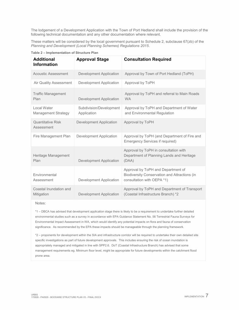
The lodgement of a Development Application with the Town of Port Hedland shall include the provision of the following technical documentation and any other documentation where relevant.
These matters will be considered by the local government pursuant to Schedule 2, subclause 67(zb) of the Planning and Development (Local Planning Schemes) Regulations 2015.
Table 2 – Implementation of Structure Plan
Additional Information
Approval Stage Consultation Required
Acoustic Assessment Development Application Approval by Town of Port Hedland (ToPH)
Air Quality Assessment Development Application Approval by ToPH
Traffic Management Plan Development Application
Approval by ToPH and referral to Main Roads WA
Local Water Management Strategy
Subdivision/Development Application
Approval by ToPH and Department of Water and Environmental Regulation
Quantitative Risk Assessment
Development Application Approval by ToPH
Fire Management Plan Development Application Approval by ToPH (and Department of Fire and Emergency Services if required)
Heritage Management Plan Development Application
Approval by ToPH in consultation with Department of Planning Lands and Heritage (DAA)
Environmental Assessment Development Application
Approval by ToPH and Department of Biodiversity Conservation and Attractions (in consultation with OEPA *1)
Coastal Inundation and Mitigation Development Application
Approval by ToPH and Department of Transport (Coastal Infrastructure Branch) *2
Notes:
*1 – DBCA has advised that development application stage there is likely to be a requirement to undertake further detailed
environmental studies such as a survey in accordance with EPA Guidance Statement No. 56 Terrestrial Fauna Surveys for
Environmental Impact Assessment in WA, which would identify any potential impacts on flora and fauna of conservation
significance. As recommended by the EPA these impacts should be manageable through the planning framework.
*2 – proponents for development within the SIA and infrastructure corridor will be required to undertake their own detailed site
specific investigations as part of future development approvals. This includes ensuring the risk of ocean inundation is
appropriately managed and mitigated in line with SPP2.6. DoT (Coastal Infrastructure Branch) has advised that some
management requirements eg. Minimum floor level, might be appropriate for future developments within the catchment flood
prone area.
8 EXPLANATORY SECTION URBIS170928 - PA0929 - BOODARIE STRUCTURE PLAN V5 - FINAL.DOCX
2. EXPLANATORY SECTION 2.1. PLANNING BACKGROUND
2.2. INTRODUCTION AND PURPOSE The purpose of this structure plan is to facilitate the development of the BSIA for a variety of heavy industrial developments, specialising in downstream resource processing. The structure plan fulfils the statutory requirements of the Town of Port Hedland’s TPS5 and the Planning and Development Regulations 2015 in establishing the appropriate framework for development.
The structure plan will coordinate the detailed land use and development of the BSIA, including the provision of proponent funded services and infrastructure. This structure plan was commissioned under the Heavy Use Industrial Lands Strategy (HUILS) to guide heavy industrial development in the Precinct. JTSI and LandCorp are implementing the HUILS which aims to bring key new industrial estates towards a basic “project ready” status, by achieving land-based approvals in preparation for occupancy by significant industrial projects.
The BSIA is in close proximity to the Port Hedland Port with connections to the inner harbour, the proposed outer harbour and Lumsden Point through strategic infrastructure corridors and linkages. The proximity of the Port to the BSIA has the potential to create a world-class heavy industrial estate which specialises in multi-product, downstream resource processing.
The development opportunities, synergies and potential connections of the BSIA to surrounding land uses and infrastructure enhance the viability of the locality for heavy industrial uses.
The formulation of the structure plan has involved an analysis of the opportunities, constraints, strengths and weaknesses relating to the BSIA. These are further detailed within the structure plan report.
The structure plan ensures that the State and National drive for diversified industry has been maintained, while balancing the needs of industrial users and sustainability of the local community. Careful attention has been paid to ensuring appropriate integration between development proposed within the BSIA and within Port land. Key local planning documents and State initiatives have been considered within this structure plan.
2.3. PURPOSE OF STRATEGIC INDUSTRIAL AREAS As Australia’s predominant State for the export of gas, iron ore, petroleum and other minerals, Western Australia is pivotal to the supply of resources to the Asian region and beyond. Led by the Department of Jobs, Tourism, Science and Innovation (JTSI) and delivered by LandCorp, SIA’s are industrial land areas designed for investment in downstream processing and other strategic industrial activities. Each estate is selected for its proximity to major resource projects and key infrastructure such as roads, rail and ports.
The BSIA is planned for strategic and downstream processing industries in WA’s Pilbara region. The BSIA has been master planned to accommodate a range of mineral, gas processing and other strategic industries requiring access to the nearby Port. Boodarie is also connected to key regional road, gas, power and water infrastrastructure networks. Proponents that have already chosen to invest in the BSIA include Alinta power station and Sub161 compressed natural gas.
Land is available in the BSIA for large scale noxious and heavy strategic and downstream processing industries based on the local resources such as iron ore, salt and other strategic industrial activity, and will be allocated by the JTSI through the lease arrangement with LandCorp.
2.3.1. Background to Structure Plan In 2014, the Boodarie Development Plan (DP) was prepared in accordance with existing provisions of the Town of Port Hedland Town Planning Scheme No. 5 (TPS5). In this regard, clause 5.2 and Appendix 6 of TPS5 outline the matters which should be addressed, and the advertising requirements, for a DP.
The DP was advertised in accordance with the provisions of Clauses 4.3.3 and 4.3.4 of TPS5 relating to advertising, and advertising occurred concurrently with Amendment 71 which introduced the Boodarie Strategic Industrial Area into the Scheme, and the Strategic Industry Zone as a Development Area. A pre-
URBIS 170928 - PA0929 - BOODARIE STRUCTURE PLAN V5 - FINAL.DOCX
EXPLANATORY SECTION 9
advertising period also occurred when the Town referred the DP informally to relevant agencies prior to the formal advertising period.
The DP was prepared and advertised as if the provisions proposed to be introduced into the Scheme for Boodarie via Amendment 71, had already existed.
The advertising period for the concurrent Amendment and Development Plan ran from 12th November 2014 until the 7th January 2015 with a total of 10 submissions were received primarily from government agencies, with no objections, but providing advice, which will be discussed below. Following minor changes being made to the Amendment documentation, Amendment 71 was gazetted on 19th July 2016.
The Department of Planning Lands and Heritage (DPLH) advised in August 2016 that although the DP was prepared and advertised under existing Scheme provisions at the time, its opinion was that the adoption of the Planning and Development (Local Planning Schemes) Regulations 2015 (‘the Regs), in August 2015, effectively overrode the DP provisions in the Scheme, by the adoption of the Deemed Provisions for local planning schemes via Schedule 2, Part 4, relating to structure plans.
DPLH advised that as there was no ‘head of power’ within the Scheme to deal with initiating, advertising, or finalising the DP, readvertising is required as the Regs were only gazetted after advertising occurred. The WAPC has issued a letter, dated 9th August 2016, which it advised provides the ‘head of power’ required to facilitate the adoption of the DP as a SP, under clause 15(c) of the Regs. The WAPC has determined that a SP ‘for the area is required for the purposes of orderly and proper planning’.
The DPLH further advised that given Boodarie will be advertised and adopted as a structure plan, the DP document would need to be reformatted into a SP consistent with the WAPC Structure Plan Framework (August 2015).
DPLH advised that once the SP has been submitted to the Town, clause 17 of the Regs (and subsequent) provisions are applicable to the process, to ensure the structure plan is adopted via a valid process in accordance with the current planning framework.
2.3.2. Consultation As noted, BSIA has previously been the subject of 2 prior advertising processes. Submissions were received from a range of agencies as follows:
BHP Billiton Iron Ore Department of Biodiversity Conservation and Attractions (formerly Department of Parks and Wildlife) Pilbara Ports Authority Roy Hill Infrastructure Pilbara Development Commission Department of Mines, Industry Regulation and Safety (formerly Department of Mines and Petroleum) Water Corporation Telstra Optus Department of Planning Lands and Heritage (formerly Department of Lands) Department of Planning Lands and Heritage (Department of Indigenous Affairs) Department of Health Main Roads WA Tourism WA Port Hedland Chamber of Commerce
A summary of the submissions received, with the City’s comments and recommendations presented to elected members at the Council’s ordinary meeting of 24 June 2015 is attached as Appendix L.
More recently, JTSI and LandCorp have held discussions with the following agencies with the following outcomes:
Department of Water and Environmental Regulation (formerly Department of Water) Department of Biodiversity Conservation and Attractions (formerly Department of Parks and Wildlife) Department of Transport Coastal Infrastructure Branch
In preparing the structure plan, discussions have also been held with the Department of Planning Lands and Heritage (formerly Department of Planning) and the Town of Port Hedland to confirm the content and direction of the structure plan.
10 EXPLANATORY SECTION URBIS170928 - PA0929 - BOODARIE STRUCTURE PLAN V5 - FINAL.DOCX
2.4. LAND DESCRIPTION 2.4.1. Location Located within the Town of Port Hedland, the BSIA is situated 10km south of Port Hedland and 4km west of South Hedland (Figure 1).
The structure plan applies to the Strategic Industry Zone adjacent the Great Northern Highway.
The area is separated from sensitive uses in the TPS5 by a Special Control Area buffer. The structure plan area includes infrastructure corridors that provide connections to the Port of Port Hedland (‘the Port’). The Structure Plan map conceptually identifies how these corridors extend outside of the structure plan area, connecting into Port land to the north and extending further south from the BSIA.
2.4.2. Area and Use The BSIA consists of approximately 4,652.5ha of largely undeveloped land with small scale land uses in operation. The area within the Boodarie Industrial Buffer Special Control Area (SCA) comprises 15,736 hectares with a number of similarly small scale land uses. These include sand extraction, mineral storage leases and power generation facilities. The site is bisected by a number of regional service mains, including the APA Group gas pipeline, which comprises the main infrastructure servicing the Alinta gas fired power station.
The Structure Plan boundary includes all of that land identified within Amendment No.71, to ensure that the environmental, hydrological and other provisions of the Structure Plan apply to the whole area identified within the Scheme, including the future development of the Boodarie Central Infrastructure Corridor.
2.4.3. Legal Description and Ownership There are many leasehold land tenure arrangements within the BSIA. An extensive land tenure ordinance report undertaken by Whelans - Current Land Use and Interests Report is attached as Appendix I under External Reports.
The majority of the land is currently held by the Crown and is the subject of the “Boodarie” Pastoral Lease held by BHP Billiton (BHPB), the De Grey - Mullewa stock yard route, a Stock Holding Reserve vested in the Town of Port Hedland and a number of General Purpose and Mining Leases for Infrastructure and sand extraction purposes (Refer Appendix A).
The land is subject to numerous power, gas and water easements.
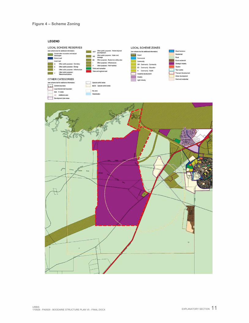
2.5. PLANNING FRAMEWORK 2.5.1. Zoning and Reservations 2.5.1.1. Town of Port Hedland Town Planning Scheme No. 5 The land subject to the BSIA Structure Plan is zoned ‘Strategic Industry’ under the Town of Port Hedland TPS 5 (refer Figure 4). In addition, TPS5 identifies the subject land as being contained within the boundary of the Boodarie Industrial Buffer Special Control Area.
URBIS 170928 - PA0929 - BOODARIE STRUCTURE PLAN V5 - FINAL.DOCX
EXPLANATORY SECTION 11
Figure 4 – Scheme Zoning
12 EXPLANATORY SECTION URBIS170928 - PA0929 - BOODARIE STRUCTURE PLAN V5 - FINAL.DOCX
Parts V to VII of TPS5 require comprehensive planning to be undertaken prior to strategic industrial development occurring on land within the ‘Strategic Industry’ zone.
Clause 5.3.10 of the Scheme identifies the following Precinct Objectives for Boodarie:
Boodarie Strategic Industrial Area
a. Establish synergies and clustering of co-located industries, transport and infrastructure, including port related and upstream industrial activities;
b. Give priority to strategic resource processing industrial development comprising downstream processing such as iron ore processing, petro and gas processing, non-ferrous processing, noxious and port dependent processing, and other strategic industries;
c. Promote proponent initiated industrial subdivision and development to facilitate strategic downstream resource processing;
d. Enable support industries provided they are complimentary to and offer goods and services that directly support and are compatible to downstream resource processing and other strategic industries;
e. Facilitate local employment and economic growth opportunities through downstream resource processing and strategic industrial development.
Under clause 6.7.3 of TPS5, in considering applications for planning approval in the Strategic Industry Zone, Council shall ensure that the proposal:
a. Optimises the effectiveness of the zone as a strategic industrial area and utilises major infrastructure, creates symbiosis with other industries or includes resource processing industry
b. Is significant to the regional and/or state economies, or c. Provides goods and services which directly support or compliment industries described in (a) and (b)
of this subclause; and d. Minimises or offsets impacts on local infrastructure, economic and community development.
Clause 6.7.4 identifies that the purpose of the Strategic Industry Zone is to ‘accommodate strategic industries and, notwithstanding the provisions of any other part of the Scheme, development which may impede the operation of such industries shall not be permitted within the Strategic Industry zone or the Boodarie Industrial Special Control Area’.
All applications for development under TPS5 will be assessed and determined by Council including consultation with relevant State departments and other relevant authorities, as set out in the Scheme and the Structure Plan, to ensure the proposal does not conflict with intentions for industry and infrastructure development in the zone.
Land Use Permissibility is outlined within the Zoning Table of TPS5.
Notwithstanding the above, development within the BSIA shall have due regard to the requirements of the structure plan.
TPS5 includes a range of provisions under Section 7.2 relating to land use permissibility and development within the Boodarie Industrial Buffer Special Control Area (SCA). The SCA comprises an area surrounding the BSIA which provides a buffer between future industrial uses and other more sensitive land uses in the locality.
Generally, these provisions seek to prevent the development of sensitive uses in proximity to industrial activities, however the underlying zoning of the land within the SCA is ‘Rural’. The existing land use permissibility for the ‘Rural’ zone is set out in TPS5, and clause 7.2.1 sets out those uses considered to be ‘sensitive land uses’.
Clause 7.2.2 sets out those matters within the SCA that must be demonstrated within any application for planning approval. In particular, for any application over land within this area, the application shall be referred to relevant State government agencies, Government Trading Enterprises and other stakeholders for comment.
URBIS 170928 - PA0929 - BOODARIE STRUCTURE PLAN V5 - FINAL.DOCX
EXPLANATORY SECTION 13
2.5.2. Planning Strategies 2.5.2.1. State Planning Strategy 2050 The WAPC released the State Planning Strategy in June 2014. The strategy provides a collaborative approach to planning within Western Australia, reflecting the need to inform the planning framework in light of the growth and change occurring within the various sectors.
Key strategic directions are set out to influence the development of Western Australia. The strategic directions and objectives relevant to the development of the BSIA can be summarised as:
Facilitating coordinated and sustainable economic development through innovation and diversity in development and investment in infrastructure.
Facilitating a sustainable supply of affordable land for future development, particularly in regional hotspots.
The State Planning Strategy identifies the North West Sector as a key contributor to Australia’s GDP. This is primarily driven by the expansion in the resources sector and ever increasing demands. The Strategy outlines the opportunities for growth within both the economic and social sector, identifying the key interdependencies between economic and population growth.
Diversification of economic developments and business operations is encouraged in order to secure a sustainable economic future for the North West Sector.
The approaches set out within the Strategy to achieve the relevant objectives include:
Ensure an appropriate and unconstrained land supply is available. Ensure the required infrastructure is in place to support growth and development. Provide opportunities for diversification in the economy. Promote Industrial Ecology and clustering of ancillary industries. Ensure appropriate accessibility is provided through movement networks and connections within
Western Australia, nationally and internationally. Encourage development to occur in defined precincts to avoid incompatible uses restricting
development.
The development of the BSIA is in line with the objectives of the State Planning Strategy. The structure plan facilitates strategic industrial land which provides additional support industries to the existing economic drivers within Port Hedland.
2.5.2.2. Transport Impact Assessment Guidelines In August 2016, the WAPC adopted Transport Impact Assessment Guidelines. Given the considerable scope of work which has already occurred in the transport space for Boodarie, the status of acceptance and approval by MRWA and the Town, and the extensive scale of Boodarie, the DPLH advised in October 2016 that a Transport Impact Assessment is not required in this instance.
2.5.2.3. Transient Workforce Accommodation Strategy The Transient Workforce Accommodation Strategy was prepared by the Town of Port Headland in October 2014. The purpose of the Strategy is to manage the development of future transient workers accommodation (TWAs) within the Town of Port Headland. One of the key aims of the Strategy is to encourage a more permanent accommodation types to be developed which are provide for more integration with the town.
The Strategy provides a preferred location map detailing the where TWA’s should be located. The BSIA is not identified as a preferred location for TWA’s. However, under the Strategy, existing TWA sites approved prior to the release of the Strategy may continue operations. Amendment 71 amended the Zoning Table to preclude TWA sites from the Boodarie area.
2.5.2.4. Port Hedland Area Planning Strategy The Port Hedland Area Planning Study (2003) provides a framework to guide State decision-making and detailed planning at the local level for a planning horizon of 20 to 25 years.
The Strategy identifies the potential for downstream resource processing associated with the resource extraction projects which were at the time, being established in the locality.
14 EXPLANATORY SECTION URBIS170928 - PA0929 - BOODARIE STRUCTURE PLAN V5 - FINAL.DOCX
The need to provide land and infrastructure to provide for the diversifying economy was acknowledged. The Strategy aims to provide for the indicative planning needs, land uses, expansion areas, and future infrastructure within Port Hedland in order to avoid land use conflicts and promote development.
The establishment of the BSIA is a pro-active approach to provide land and infrastructure in a suitable location for strategic industry. The Strategy envisages the BSIA as having a heavy industry core surrounded by support industry, with linkages to the Port.
2.5.2.5. Heavy Use Industrial Land Strategy As mentioned earlier in this report, this structure plan was commissioned under HUILS to guide heavy industrial development in Boodarie, Port Hedland. HUILS identified key new industrial estates for the development of heavy industry within Western Australia.
The HUILS aims to facilitate the initial stages of these estates to reach project ready status and allow significant industrial developments to be established. JTSI is responsible for implementing the strategy, and funding has been allocated to enable this.
The BSIA was identified as a priority estate by JTSI on the basis of its significant potential to support downstream processing in Port Hedland. JTSI has progressed the initial planning phase, leading to the preparation of this structure plan in facilitating the release of land for development.
2.5.2.6. Pilbara Planning and Infrastructure Framework The Pilbara Planning and Infrastructure Framework (2012) provides the strategic framework for the Pilbara region to 2035. The Framework acknowledges that an increase in population within the region will need to be supported by a robust, diverse and sustainable economy. The initial diversification is to stem from the industry supply chain and downstream resource processing. Future diversity is seen to come from an increase in knowledge based industries and increased export capacity.
A well connected transport network is highlighted as a key component in the expansion of economic activity within the Pilbara. Providing for accessibility and connectivity through individual transport networks and between various modes of transportation is required. Facilitating locally, regionally, nationally and internationally connected networks which can be utilised in all weather conditions is paramount in the ongoing viability of development within the region.
The need to supply significant amounts of industrial land to support the expansion of existing projects and facilitate future development is acknowledged. The unique drivers for land are recognised, as are the requirements for large areas of land to meet operational requirements. Strategic Industrial Areas, including the BSIA will provide for much of the demand as outlined within the HUILS.
2.5.3. Planning Strategies 2.5.3.1. Pilbara’s Port City Growth Plan The Town of Port Hedland document provides high level, strategic guidance for the future development of South Hedland, Port Hedland and surrounding areas. The Town of Port Hedland and WAPC endorsed the Pilbara’s Port City Growth Plan in December 2012 as the Town’s Local Planning Strategy, replacing the Land Use Master Plan 2008.
The growth plan seeks to deliver sustained and diversified economic growth, population growth and to enhance community and environmental opportunities through the revitalisation of the Town of Port Hedland locality. The key connections between economic growth and population growth are highlighted consistently within the document.
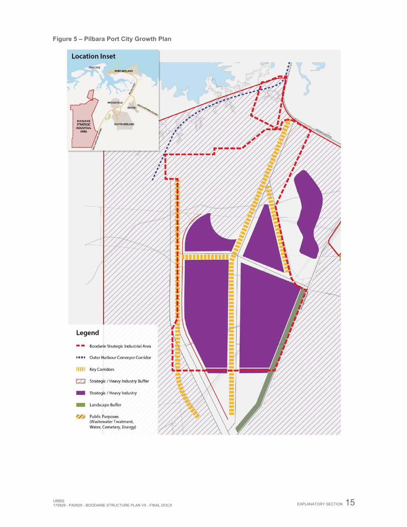
Industrial growth within Port Hedland is to allow for the orderly release of industrial land to allow for economic growth across a range of industries. Land within planned industrial areas such as BSIA is to be released in order to facilitate the movement of heavier industry from the existing industrial areas, such as Wedgefield, and allow for the expansion of additional heavy/strategic industry (refer Figure 5).
The growth plan allows for flexibility in planning areas through the use of the precincts. This allows local level planning to occur in a manner which responds to the opportunities and challenges that occur as the Port Hedland locality grows.
URBIS 170928 - PA0929 - BOODARIE STRUCTURE PLAN V5 - FINAL.DOCX
EXPLANATORY SECTION 15
Figure 5 – Pilbara Port City Growth Plan
16 EXPLANATORY SECTION URBIS170928 - PA0929 - BOODARIE STRUCTURE PLAN V5 - FINAL.DOCX
2.5.4. Other Approvals and Decisions 2.5.4.1. Scheme Amendment No. 71 Amendment 71 was gazetted on 19th July 2016. A copy of the gazettal notice has been provided in Appendix M.
The Amendment facilitated the following changes to TPS5 for Boodarie:
Identify the Boodarie Strategic Industrial Area as a Structure Plan Area under the Scheme. Insert Objectives for the Boodarie Strategic Industrial Area to indicate the preferred land uses
and development and provide additional guidance for Council in determining development applications.
Modify Section 7.2 relating to the ‘Boodarie Industrial Buffer Special Control Area’ to provide more detailed guidance on land uses appropriate within the buffer and preclude sensitive uses, defined through the Scheme Amendment, and providing guidance to the Town when determining planning applications for the area.
Inserting a clause requiring the Town to refer proposals within the Boodarie Industrial Buffer Special Control Area to relevant stakeholders for comment.
Rezoning a portion of Lot 203 from ‘Rural’ to reserve for ‘Other Purposes: Infrastructure’ to allow for the construction of infrastructure linking the port to the Boodarie Strategic Industrial Area.
Inserting additional use provisions relating to Lot 5164 Shoata Road, South Hedland, which is located within the buffer, to allow the conditional continuation of the Golf Course and Horse Training Facility land uses.
Amending Appendix 5 to identify the BSIA and Lot 203 as ‘Other Purposes Infrastructure’ and Lot 372 as ‘Other Public Purposes: Port Facilities’ as a Development Plan area.
Insert additional matters to be addressed by Structure Plans for the ‘Strategic Industry’ zone in Appendix 10, and allowing for a Development Plan to require additional conditions.
Amending the zoning table to allow for the development of a ‘Fuel Depot’ within the Strategic Industry zone, subject to Councils discretion and the adverting of any proposal for that use; and changing ‘Transient Workforce Accommodation’ to a not permitted use.
Amending the Scheme Map.
2.5.4.2. Subdivision Lots 366 and 600 Boodarie Station Access Road were approved for subdivision March 2016 (WAPC Ref: 153431). The lots comprise approximately 180ha of land located 14km south-west of the Port Headland town centre within the Boodarie Strategic Industrial area. The subdivision allowed for the creation of the following lots: Lot 366: Create two (2) lots, including one (1) balance lot, three (3) roads and one (1) drainage reserve for the purposes of industrial development and associated infrastructure. Lot 600: Create two (2) lots, including one (1) balance lot for the purposes of industrial development. Lot 366 and Lot 600 are zoned Strategic Industry under the structure plan. The subdivision is in accordance with the intentions of the structure plan and will facilitate the development of the sites for industrial uses on a lease arrangement.
A copy of the approved subdivision plan and WAPC subdivision approval has been provided in Appendix J.
2.6. IMPLEMENTATION STRUCTURE 2.6.1. Governance Structure JTSI is the Lead Agency for the BSIA with the ongoing management of the BSIA undertaken by LandCorp. The PPA is the management authority of approvals on Port land depicted within the structure plan at Figure 2.
The development of the BSIA is to be proponent driven as guided by JTSI and LandCorp. Proponents are therefore responsible for the construction of all infrastructure required to service their sites. The benefits associated with shared services are acknowledged and LandCorp and JTSI will require that the proponent’s servicing strategy investigate the opportunity for the construction of shared services to benefit the whole of the BSIA.
URBIS 170928 - PA0929 - BOODARIE STRUCTURE PLAN V5 - FINAL.DOCX
EXPLANATORY SECTION 17
Expressions of Interest on the lease of lots shall include a business case which appropriately justifies the location and activity in accordance with the structure plan and Precinct Plan contained within this report. These will be reviewed by JTSI and LandCorp. If an industrial developer demonstrates as part of the business case that it should be located in an alternative location to the preferred precinct, this may occur subject to business case approval by JTSI and LandCorp.
Prior to lodgement of a Development Application with the Town of Port Hedland, endorsement of a proponent’s proposal must be obtained from LandCorp and JTSI.
As a proponent driven development, staged development of the BSIA does not imply a commitment from either State or Local Governments to provide serviced land or the infrastructure required to make the area function. Proponents are therefore responsible for the construction of infrastructure required for their business.
As part of the determination and approval process, proponents are required to undertake detailed site investigations in accordance with the TPS5 and other State Policies and achieve associated approvals from relevant referral agencies.
If considered necessary, the Town of Port Hedland may permit the structure plan to be extended outside the BSIA to facilitate by-product Storage, where in its opinion this would not prejudice the orderly and proper development of the area.
2.6.2. Lease and Development of Lots LandCorp will hold tenure of the BSIA, and land will be leased to proponents. When considering Business Case submissions from industry proponents seeking to establish within the BSIA the JTSI and LandCorp will consider the proposal in the context of the Structure Plan, the supporting technical reports and operational requirements of the BSIA. The PPA will hold tenure of port land and will consider any development proposals and grant leases, licences and easements.
Prior to lodgement of proponents’ planning application for consideration by the Town of Port Hedland, or undertaking works, it is a requirement that proposals be endorsed by JTSI and LandCorp.
In the event that green title subdivisions are pursued in assembling land to be leased to proponents, it is anticipated that standard conditions of subdivision would be applied on a case-by-case basis (as referred to in section 1.5.2 (iv), together with those outlined in Appendix G.
2.6.3. Developer Funding As a result of the size, nature and staging and development timeframes associated with the development of the BSIA, all infrastructure and servicing is to be proponent driven and funded.
To facilitate the appropriate timing of infrastructure and cost recovery for the foundation tenants, details of and arrangements for the delivery of such infrastructure and servicing should be provided as part of the Servicing Strategy.
There is no commitment from either State or Local Governments to produce serviced land or provide the necessary infrastructure required to make the area function.
2.6.4. Time Management – PAM Reserve When in use the pre-Assembled Modules (PAM’s) reserve will require time use management to regulate any impact on the operation of the BHP Goldsworthy Rail Line. Preparation of an agreement between rail operators and the Estate manager will be required.
2.6.5. Integration with Port Hedland Port LandCorp and JTSI have consulted with the PPA regarding infrastructure connections and berthing which are under the Port’s jurisdiction. Ensuring sufficient allocation of berths in the inner and proposed outer harbours, and connections to and from the BSIA is critically important. The PPA is supportive of the development of the BSIA, and has recently worked with LandCorp to resolve the interface with the Port. PPA has finalised its Multi User Outer Harbour (MUOH) Port Master Plan.
18 EXPLANATORY SECTION URBIS170928 - PA0929 - BOODARIE STRUCTURE PLAN V5 - FINAL.DOCX
Worley Parsons was commissioned by JTSI to prepare a Combined Port Area and Boodarie Master Plan Technical note (refer Appendix XIII) in recognition of the need for co-ordination between the Port and the BSIA. The purpose of this technical note is to document the preparation of the resulting Combined Port Area and BSIA Master Plan, adopting the two plans as the basis of this process and addressing any outstanding issues at the interface with these plans.
As a consequence of the findings and recommendations of the Worley Parsons Technical Note, modifications have been made to the structure plan including fine tuning to the alignment of the shared infrastructure corridors. The various supporting reports included as Appendices of the BSIA Structure Plan have been reviewed in the context of the technical note and it was concluded that it did not have any consequence to the findings of the supporting reports. It was determined that it was therefore not necessary to update the supporting reports to reflect the modified structure plan.
2.7. PRECINCT REQUIREMENTS i. The Precinct Plan (Figure 3) contained within the structure plan is intended to guide the location of
land uses within the BSIA. As industries locate over time, the Precincts can be reassessed. If an industrial developer demonstrates as part of the business case that the activity should be located in an alternative location to the preferred precinct, this may occur subject to business case approval by JTSI and LandCorp.
ii. Land use and development within the structure plan is to be in accordance with TPS5 Appendices 5 and 10. All subdivision and development is to be in accordance with the requirements of TPS5.
iii. Notwithstanding the above, development within the BSIA is subject to the requirements of the structure plan and may only be permitted when it has regard to these requirements.
iv. Additional to complying with the provisions of the structure plan, proponents are required to seek planning approval prior to the commencement of any works in accordance with the TPS5 provisions.
v. A departure or alteration to the BSIA Structure Plan may be advertised for public comment in accordance with the TPS5.
URBIS 170928 - PA0929 - BOODARIE STRUCTURE PLAN V5 - FINAL.DOCX
SITE CONDITIONS AND CONSTRAINTS 19
3. SITE CONDITIONS AND CONSTRAINTS 3.1. BIODIVERSITY AND NATURAL AREA ASSETS 3.1.1. Vegetation Description A Flora and Fauna Assessment was undertaken by GHD in June 2010. The results of this are summarised below, with the full report attached at Appendix V.
The BSIA falls within the Roebourne sub region of the Pilbara Biogeographic region of Western Australia. The environment of this sub region has been described as coastal and sub-coastal plains with a grass savannah of mixed bunch and hummock grasses and dwarf shrub steppe of Acacia stellaticeps or A. pyrifolia and A. inaequilatera (Kendrick and Stanley, 2001). The uplands of the region support Triodia hummock grasslands and the ephemeral drainage lines support Eucalyptus victrix or Corymbia hamersleyana (Kendrick and Stanley, 2001).
Broad scale mapping (Beard, 1979) indicates two vegetation associations are present within the BSIA. The majority of the BSIA is within vegetation association 589, described as Short bunch grassland - savanna / grass plain (Pilbara) / Hummock grasslands, grass steppe; soft Spinifex. The northern and southern parts of the BSIA are within vegetation association 647 described as Hummock grasslands, dwarf- shrub steppe; Acacia translucens over soft Spinifex.
The vegetation in the BSIA was classified into nine vegetation types, including cleared/disturbed vegetation, where clearing or other activities have fundamentally altered the composition of the native vegetation. There is considerable overlap between vegetation communities due to the similarity of underlying geology and landform.
The vegetation within the study area is dominated by low open heath over tussock grasslands, with changes due to differing dominance of individual grass/Triodia species, fire and other disturbances. Tussock grasslands are present with emergent tree overstorey species (Eucalypt and Acacia) on the sandplains.
Of note, there are three vegetation communities that samples have not been obtained from. These included areas with very few species present, such as open tidal flats/creekline and cleared/degraded areas. The tidal flats vegetation is too open to incorporate traditional plot based or relief surveys. In the cleared/degraded areas vegetation is absent, or with flora species known to respond to disturbances.
If the invert levels estimated for the pit tests become deeper than currently proposed or the road swale locations drastically deviate from the current locations proposed, between the time of writing this report and when construction commences, then GHD suggests further soil investigation may be required.
3.1.2. Vegetation Extent Type and Status A vegetation type is considered underrepresented if there is less than 30 percent of its original distribution remaining. The remaining extent of the vegetation associations present within the BSIA is considered intact, with close to 100% of the pre-European extent of the vegetation types considered to be remaining.
3.1.3. Vegetation Condition The vegetation condition of the BSIA was rated using the vegetation condition rating scale developed by Keighery (1994) that recognises the intactness of vegetation as defined by the following:
Completeness of structural levels. Extent of weed invasion; Historical disturbance from tracks and other clearing or dumping. The potential for natural or assisted regeneration.
The native vegetation within the study area was assessed to be predominately in Excellent condition. The vegetation structure within much of the BSIA however, has been severely impacted by fire with evidence of fire scarring occurring. Other disturbances across the study area include tracks/roads, power lines, cattle grazing, and the existing Alinta power station.
Weed species are present within the study area, with the most common, Buffel grass, occurring primarily along the edges of tracks and roads and in other previously disturbed areas. Kapok Bush was also widespread along the creekline within the proposed powerline route.
20 SITE CONDITIONS AND CONSTRAINTS URBIS170928 - PA0929 - BOODARIE STRUCTURE PLAN V5 - FINAL.DOCX
3.1.4. Threatened Ecological Communities No Threatened Ecological Communities or Protected Ecological Communities were identified as occurring within the study area during the survey.
3.1.5. Flora Species Vegetation within the study area is considered to represent a moderate degree of species diversity. A total of 144 taxa from 48 families were recorded from the study area. This list includes subspecies (subsp.), variations (var.), and hybrids (x). Two collections could only be identified to general level or could not be positively identified to species level due to lack of flowering parts or fruiting bodies.
3.1.6. Significant Flora Species No Declared Rare or Priority Flora species were recorded during the field survey.
One of the species collected from the site Stemodia lathraia (identification confirmed by Robert Davis WA Herbarium) represents a significant (500km) range extension for this species. This species has only previously been collected from the Kimberley region.
A previously undescribed species of Phyllanthus (Phyllanthus simplex sen.lat) currently being described by Ian Telford at Australian National Herbarium) was collected. This species is not recognised as being of conservation significance.
3.1.7. Introduced Flora Three weed species were recorded within the survey area; *Cenchrus ciliaris (Buffel Grass), *Aerva javanica (Kapok Bush), and *Chloris barbata (Purpletop Chloris). These species were generally concentrated in previously disturbed areas such as along tracks and roads.
3.1.8. Mulgara Fauna Mulgara (Dasycercus cristicauda) is a conservation significant fauna species that is known to occur within the Port Hedland area. Mulgara have recently been recorded in the Wedgefield area in Port Hedland. Evidence of Mulgara fauna (scats and burrows) was observed within the BSIA during the field survey. A detailed fauna survey would be required to verify the presence of this species.
On 25th November 2016, DPaW advised JTSI by email that:
‘there has been a change in the species of Mulgara considered to be present in the Port Hedland area. It is likely that all Mulgara observed in Port Hedland are the Priority 4 species of Mulgara (Dasycercus blythi) rather than threatened Mulgara (Dasycercus cristicauda), ranked vulnerable under the Commonwealth Environment and Biodiversity Protection Act 1999. During detailed environmental studies these changes should be accounted for.’
The majority of the study area was found to contain native vegetation in excellent condition, offering suitable habitat for native fauna. Some areas of the study area have been subject to inappropriate fire regimes that have reduced the habitat value in those areas. Clearing for tracks, roads, power lines, and other infrastructure (including the power station) have also reduced the habitat value within some sections of the study area.
The vegetation type described as Acacia stellaticeps low closed heath over tussock grassland of Triodia schinzii and T. epactia was found to contain prime habitat for Mulgara as evidence of the Mulgara species has been found throughout this vegetation type. These areas contained particularly high habitat value.
LandCorp has received approval for the clearing of not more than 81.35Ha of this habitat from the Department of Water and Environmental Regulation, which is attached as Appendix F. Importantly, the approval includes a management plan setting out a process for the identification of Mulgara and relocation to suitable habitat. It is anticipated that this process would be typical for the balance of the BSIA.
3.2. LANDFORM AND SOILS 3.2.1. Land Systems Land systems are described in terms of geology, landscape, soil and vegetation types. Van Vreeswyk et al. (2004) completed an inventory of the 102 land systems occurring in the Pilbara Region.
URBIS 170928 - PA0929 - BOODARIE STRUCTURE PLAN V5 - FINAL.DOCX
SITE CONDITIONS AND CONSTRAINTS 21
The BSIA is predominately within the Uaroo land system that is described as broad sandy plains supporting shrubby hard and soft spinifex grasslands. Land to the north of the BSIA is within the Littoral land system. The Littoral land system is described as bare coastal mudflats with mangroves on seaward fringes, samphire flats, sandy islands, coastal dunes and beaches.
3.2.2. Geology The study area is located within the Abydos Plain. The geology of this area is described as Quarternary alluvium near the coast, with Archean granite; other Archean rocks outcropping in small hills, ranges and dykes being located further inland.
The geology of the Uaroo land system is described as Quaternary colluvium and alluvium. The geology of the Littoral land system consists of quaternary mudflat deposits, clay, salt and sand and eolian sand.
3.2.3. Soils The gradients within the BSIA are very moderate, with the majority between 0% and 1%. Essentially the site grades south to north from the highest point of 18 metres AHD to the lowest of 8 metres adjacent to the South West Creek near the Port Authority’s boundary.
A prominent sand ridge transvers the western margin of the site on a north to south trend and having an average elevation of 16 metres AHD. This ridge and a second ridge further west co-jointly act as a physical flood barrier to Turner River.
The site comprises Pindan clayey sands consisting of Pleistocene red brown flood plain alluvium comprising silty sands.
3.2.4. Geotechnical Analysis GHD undertook Geotechnical Investigations and an Acid Sulphate Soil investigation over the BSIA in January 2013. The results of this are summarised below, with the full report attached at Appendix IV.
Generally, the investigation indicates that the soil conditions are reasonably consistent across the entire structure plan area and comprise of a topsoil layer overlying mixed flood plain deposits. The floodplain deposits were observed to consist of an upper silty sand unit overlying clayey sand. Further, iron cemented layers were locally intersected within the clayey sand.
To expedite the initial stages of the development, LandCorp required more detailed investigations to facilitate the early release of Stage 1 and Stage 2, with the balance of the development area to be completed when practical. Stage 1 comprises an area of approximately 460 hectares to the south of Boodarie Station Access Road, whilst Stage 2 is approximately 310 hectares in area located north of Boodarie Station Access Road. The balance of the study area designated ‘Preliminary Study Area’ is approximately 4,000 hectares in area.
Stage 1:
Stage 1 is located to the south of Boodarie Station Access Road and is generally flat lying, situated within an elevation range of RL+10.0mAHD to RL+11.5mAHD (Australian Height Datum). The surface is lightly vegetated with low lying shrubs and grass.
A basic summary of findings for the Stage 1 area is as follows:
Topsoil within Stage 1 comprises fine to medium grained sand / silty sand, ranging in depth from 0.2 to 0.3 metres with variable organic content.
The upper silty sand unit comprising pale brown to brown, fine to medium grained sand, ranging in depth 0.0 to 1.6 metre with low to none plasticity silt, and is considered appropriate for re-use as an engineered fill.
The clayey sand unit, typically comprises brown, fine to medium grained sand, extending beyond the depth of the test pits, with low to medium plasticity clay and a trace to some gravel. These soils are reactive and are sensitive to variations in moisture content.
Stage 2:
Stage 2 is located north of Boodarie Station Access Road and is generally flat, similar to Stage 1, situated within an elevation range of RL+11.5mAHD to RL+12.0mAHD.
22 SITE CONDITIONS AND CONSTRAINTS URBIS170928 - PA0929 - BOODARIE STRUCTURE PLAN V5 - FINAL.DOCX
A basic summary of the results for the Stage 2 area is provided below:
Topsoil within the Stage 2 area was intersected in all locations at depths between 0.2 and 0.4 metres and consisted of loose, pale brown, fine to medium grained sand.
The upper silty sand unit observed in Stage 2 was similar to that in Stage 1, comprising pale brown, fine to medium grained sand, with nil to low plasticity silt ranging in depth from 0.0 to 1.8 metres. This sand unit is considered appropriate for re-use as engineered fill.
Similar to Stage 1, the clayey sand unit extended beyond the depth of test pits and consists of brown, fine to medium grained sand, with low to medium plasticity clay and traces of gravel. These soils are reactive and are sensitive to variations in moisture content.
Preliminary Study Area The Preliminary Study Area is predominately situated within an approximated elevation range of between RL+7.5mAHD and RL+17.5mAHD, with a gentle decline (approximately 1(V) in 750(H)) from south to north. A south to north trending ridge is situated along the western boundary of the site. The ridge is generally indicated to be elevated around 2m to 3m above the surrounding ground levels except at the southern extent where it is up to 5m higher in elevation.
The surface vegetation across the site generally comprises low lying shrubs and grass, with localised areas supporting young to mature trees. Existing fence lines were observed throughout the site, in particular along the fringes of Boodarie Station Access Road and the Great Northern Highway.
A total of 85 test pits were excavated to depths of between 1.0m and 4.5m. The selection of test pits was set out to provide a representative coverage of the BSIA. A basic summary of the results for the Preliminary Study Area is provided below:
Topsoil observed in all test pit locations except one, was intersected in all locations at depths between 0.2 and 0.3 metres and consisted of loose, pale brown, fine to medium grained sand.
The upper silty sand unit was observed at approximately half of the test pit locations and comprised pale brown to brown, fine to medium grained sand, with nil to low plasticity silt ranging in depth from 0.0 to 1.5 metres. This sand unit is considered appropriate for re-use as engineered fill.
The clayey sand unit was intersected in all of the test pit locations and extended beyond the depth of test pits. The clayey sand unit consists of brown, fine to medium grained sand, with low to medium plasticity clay and traces of gravel. These soils are reactive and are sensitive to variations in moisture content. The majority of the BSIA is located within a low lying area which is prone to flooding. Placement of fill will be required to achieve proposed development levels across the site. Foundation bearing capacity and soil settlement estimates note that lightly loaded industrial structures can be accommodated on the final engineered fill. Additional geotechnical investigation and analysis is necessary to support the design of heavily loaded or settlement sensitive structures. Groundwater was intersected in test pit TP76, situated at the north-west corner of the BSIA. The groundwater depth, estimated to be 4.2m from a ground surface elevation, is approximately RL +7 metres AHD. It should be noted that the groundwater level intersected during the field investigation does not necessary represent the highest expected groundwater levels.
3.2.5. Acid Sulphate Soils A review of Department of Water and Environmental Regulation Acid Sulphate Soil (ASS) risk mapping indicates the BSIA overlies an area of no known ASS risk within 3m of the natural soil surface. It does not prove conclusively there is no ASS in the area.
All sample locations for the combined geotechnical and ASS test pits were positioned within Stage areas 1 and 2 of early development or at road swale locations and drainage inverts. Soil samples were taken to 3 metres depth with the expectation on that drainage invert levels will be between 1.5 to 2.0 metres below ground level.1
1 If the invert levels estimated for the pit tests become deeper than currently proposed or the road swale locations drastically deviate from the current locations proposed, between the time of writing this report and when construction commences, then GHD suggests further soil investigation may be required.
URBIS 170928 - PA0929 - BOODARIE STRUCTURE PLAN V5 - FINAL.DOCX
SITE CONDITIONS AND CONSTRAINTS 23
Based on the fairly consistent lithological observations and the negligible potential acid generation as indicated by the laboratory results, the risk of excavating ASS during excavation of the road swales in potential early stages of development is very low. For these reasons, it is anticipated the soils to be excavated during construction of the swales to a depth of 2.0 metres below ground level will not require treatment for ASS.
3.3. GROUNDWATER AND SURFACE WATER 3.3.1.1. Groundwater Monitoring GHD installed monitoring bores at strategic locations within the BSIA and undertook baseline groundwater monitoring to determine predevelopment groundwater levels and groundwater quality over a period of 12 months. The results of this are summarised below, with the full report attached at Appendix VI.
A total of 7 groundwater monitoring wells were installed in December 2012 and the first round of groundwater level and groundwater quality monitoring was undertaken shortly thereafter. Between the third sampling in August 2013 and the fourth in October 2013, groundwater levels have stabilised, following the significant rain events recorded during the previous quarter, with reducing levels observed at two sampling sites. A groundwater level decline is observed in well GW6, which is possibly attributed to drilling activities in the area. A drop in levels has recorded at GW1, with a significant drop in groundwater levels was also noted in well GW2.
Groundwater quality has remained relatively stable with comparison to the initial round of monitoring. Groundwater quality at GW1 and GW2 is the most saline, possibly indicative of salt-water intrusion from the coast. Groundwater becomes fresher with distance to the south.
The DWMS has since been updated by GHD to include an addendum. This was at the DPLH request for the additional reserved land to be included in the Structure Plan boundary.
3.3.1.2. Watercourses Waterways and wetland areas within the Pilbara region are ephemeral, and typically flow or fill during seasonal rainfall events. A search of the Western Australian EPBC Act Protected Matters Search Tool indicates no wetlands or watercourses of significance in or adjacent to the study area. South West Creek is an ephemeral watercourse/tidal creekline.
3.3.1.3. Public Drinking Water Source Area Public Drinking Water Source Areas is a collective term used for the description of Water Reserves, Catchment Areas and Underground Pollution Control Areas as declared under the provisions of the Metropolitan Water Supply, Sewage and Drainage (MWSSD) Act 1909 or the Country Area Water Supply (CAWS) Act 1947.
The DWER has recently arranged for the abolition of the Turner River Water Reserve, which was located within the structure plan area. The DWER has confirmed that the CAWS Act 1947 no longer applies to land use activities within the structure plan area.
3.3.1.4. South West Creek – Flooding Flooding of SW Creek and storm surge areas are influential to determining the development parameters of the BSIA. Preliminary flooding and storm surge knowledge was derived from the GEMS study. Site specific detail has been provided through GHD’s District Water Management Strategy (DWMS) as outlined in Section 7.0. The final DWMS was approved by the DWER on 14th June 2016. The letter of approval is contained within Appendix K.
Studies undertaken by Jim Davies and Associates Pty Ltd (JDA) between 1994 and 2005 assessed the flooding potential of the BSIA and other infrastructure in the vicinity. The report reveals that there was significant uncertainty as to the interactions between the Turner River, South Creek and South West Creek that could result in additional flow to South West Creek during flooding of the Turner River.
Subsequent to JDA 1995, Global Environmental Modelling Systems (GEMS) undertook the Greater Port Hedland Storm-surge Study (GEMS 2000ii). GEMS suggested that the application of the predicted 100-year
24 SITE CONDITIONS AND CONSTRAINTS URBIS170928 - PA0929 - BOODARIE STRUCTURE PLAN V5 - FINAL.DOCX
storm surge level as a downstream boundary condition to the flood modelling (as adopted by JDA 1995) represents a highly unlikely event and therefore adopted the high spring tide for their flood model.
3.3.1.5. Port Hedland Coastal Vulnerability Study The Port Hedland Coastal Vulnerability Report (Cardno 2012), included as Appendix XIV under External Reports, was undertaken in order to identify the opportunities and constraints in meeting the infrastructure requirements Port Hedland faces as population and development opportunities grow. The full report is available from the Town of Port Hedland.
Port Hedland is noted to be vulnerable to impacts from tropical cyclones and pending climate change. The study covers a great deal of analysis and interpretation of modelling results to determine the combined influence of storm surge impacts in combination with flood analysis and coastal inundation. The BSIA is located within the study area, within Area 3; however, there are no results specific to the BSIA.
The DoT advised JTSI on 24th November 2016 that the inundation hazard will be the major concern for the implementation of the Structure Plan. Some management requirements eg. Minimum floor level, might be appropriate for future developments within those catchment flood prone areas.
The modelling work undertaken by Cardno (refer Appendix XIV under External Reports) specifically focuses on this BSIA locality in order to predict the impacts of flooding on the development area, along with the BSIA central infrastructure corridor, and the surrounding developments. In addition, the DWMS addresses site-specific drainage assessment, and provides further detail specific to development on the site.
The DWMS has established guidelines and a drainage master plan to which all industries must comply. This will be particularly important for sites such as Boodarie where the cost of fill is a significant factor in project development costs. All developers will require a complying framework within which to manage drainage at the boundaries of their sites to ensure effective functioning and viability of overall site drainage and fill levels. On the sites where smaller scale development takes place, such as support industrial areas, a uniform approach to coastal vulnerability and inundation must be clearly defined and enforced.
3.3.1.6. Turner River GHD undertook a study on BSIA Hydrologic and Hydraulic Analysis of the Turner River Catchment, west of the BSIA, to assess implications for the structure plan. The results of this are summarised below, with the full report attached at Appendix VII. This study conducted hydraulic modelling of the Turner River to estimate the peak 100 year water levels along the Turner River and subsequently highlight constraints on the BSIA.
The study highlighted:
Flood levels associated with the Turner River and potential effects and risks to the BSIA. Options for future sand mining around the Turner River.
The BSIA is currently afforded flood protection by the sand ridge adjacent to the Turner River. The 100 year ARI flood levels are contained within the low lying valley between Turner River flood plain east bank and the sand ridge.
In order to ensure this level of protection remains and the operations of the BSIA are not compromised by further sand mining operations, the recommendations include:
Provide for mining of the sand ridge subject to BSIA drainage levels. This is on the proviso that levels remain above the 100 year peak flood level (plus 50cm freeboard).
Construct a levee between the two ridges to eliminate flood water within the low lying valley. This would provide for mining in line with the BSIA drainage levels.
Provide for mining of the sand ridge to an extent which maintains a bund at a height consistent with the peak flood level and 500mm freeboard.
Amendment No.71
Amendment No. 71 to the Town of Port Hedland Town Planning Scheme includes several new provisions under clause 7.2.2 to provide for the appropriate consideration of the Turner River and the adjacent sand ridge as part of any new development, including extractive industry. The new clauses comprise the following:

URBIS 170928 - PA0929 - BOODARIE STRUCTURE PLAN V5 - FINAL.DOCX
SITE CONDITIONS AND CONSTRAINTS 25
(d) the likelihood of the proposed development adversely affecting the efficiency and capacity of the Turner River and surrounding landscape to safely carry and discharge floodwaters, including any backwater flows;
(e) The likelihood of the proposed development adversely affecting the safety of land zoned ‘Strategic Industry’ during flood events; and
(f) The likelihood of the proposed development adversely affecting the safety of Pilbara Port Authority land and any other adjoinin gland areas during flood events.
And inserting a new clause 7.2.3 as follows: When considering an application for planning approval with respect to land wholly or partly within the Boodarie Industrial Buffer Special Control Area, the Council shall refer the proposal to the relevant State Government Agencies, Government Trading Enterprises and other stakeholders for comment.
26 SITE CONDITIONS AND CONSTRAINTS URBIS170928 - PA0929 - BOODARIE STRUCTURE PLAN V5 - FINAL.DOCX
3.4. BUSHFIRE HAZARD A Bushfire Management Plan (BMP) was prepared by RUIC as part of an application to subdivide Lot 366 Boodarie Station Access Road into 17 industrial lots (refer Appendix I).
The BMP measured the level and type of vegetation located within the subdivision area. Most of the vegetation was found to be of low threat primarily comprising of Class C Shrub. A BAL rating of 12.5 was implemented over the majority of the site with select portions having a BAL rating of 29. This includes proposed Lots 1, 22, and 14 which required asset protection zone to be implemented with a minimum width of 3m to reduce the BAL to BAL-29.
A BMP has also been prepared by Strategen to support the structure plan (refer Appendix XIV). The outcomes of the BMP are as follows:
The BMP has been prepared based on the existing state of the on-site and surrounding fire environment
A pre-development bushfire hazard level assessment identifies the BSIA as having a ‘Low’ ‘Moderate’ bushfire hazard level. The post development state will result in even lower levels
A bushfire approaching the BSIA from the northwest or noth is likely to be the worst case bushfire scenario
A range of bushfire management measures are recommended including:
o provision of minimum 20 m Asset Protection Zones to achieve a maximum BAL–29 rating under Australian Standard AS 3959–2009 Construction of Buildings in Bushfire-prone Areas (SA 2009)
o staged vegetation clearing within development areas in advance to achieve 100 m low fuel buffers where necessary to ensure habitable building construction is not inhibited by temporary vegetation extent located within adjacent stages yet to be cleared
o construction of habitable buildings to meet the standard appropriate to the BAL for that location, regardless of building class, and to not exceed BAL–29
o design at future planning stages to ensure that all occupiers and visitors are provided with at least two vehicular access routes connecting to the surrounding public road network at all times, including during development staging
o any proposed public roads, cul-de-sacs, private driveways longer than 50 m, emergency accessways or fire service access routes to meet or exceed technical requirements of the Guidelines for Planning in Bushfire-Prone Areas (WAPC 2015b)
o implementation of and compliance with provisions of the Town of Port Hedland annual firebreak Notice
o staged implementation of water supply services as development progresses to provide a non-reticulated system that ensures an all year round supply of water to meet emergency water supply requirements
o at subsequent planning stages, preparation of and implementation of a detailed plan demonstrating the location and capacity of fire emergency water infrastructure
o at subsequent planning stages, BMPs to include a requirement for notification to be placed on title for all lots within bushfire prone areas as a condition of subdivision to ensure landowners and prospective purchasers are aware that increased building construction standards and the BMP may apply
o at development application stage, preparation and implementation of emergency evacuation plans and risk management plans for proposed high risk land uses located in areas of BAL-12.5 to BAL-29
o individual BMPs and revision of existing BMPs, including detailed BAL contour assessment on an individual lot basis, to be required at appropriate future planning stages (such as subdivision) to ensure the management measures and BAL ratings and separation distances are consistent with the final development proposal.
Implementation of bushfire management measures within the BSIA will apply to developers, prospective landowners and local government to ensure bushfire management measures are adopted and implemented on an ongoing basis. An indicative works program has been provided within the BMP to guide future planning and will need to be revised and updated as part of further bushfire planning requirements as planning stages progress.
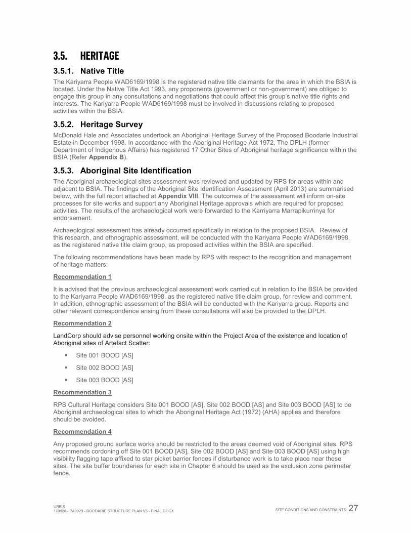
URBIS 170928 - PA0929 - BOODARIE STRUCTURE PLAN V5 - FINAL.DOCX
SITE CONDITIONS AND CONSTRAINTS 27
3.5. HERITAGE 3.5.1. Native Title The Kariyarra People WAD6169/1998 is the registered native title claimants for the area in which the BSIA is located. Under the Native Title Act 1993, any proponents (government or non-government) are obliged to engage this group in any consultations and negotiations that could affect this group’s native title rights and interests. The Kariyarra People WAD6169/1998 must be involved in discussions relating to proposed activities within the BSIA.
3.5.2. Heritage Survey McDonald Hale and Associates undertook an Aboriginal Heritage Survey of the Proposed Boodarie Industrial Estate in December 1998. In accordance with the Aboriginal Heritage Act 1972, The DPLH (former Department of Indigenous Affairs) has registered 17 Other Sites of Aboriginal heritage significance within the BSIA (Refer Appendix B).
3.5.3. Aboriginal Site Identification The Aboriginal archaeological sites assessment was reviewed and updated by RPS for areas within and adjacent to BSIA. The findings of the Aboriginal Site Identification Assessment (April 2013) are summarised below, with the full report attached at Appendix VIII. The outcomes of the assessment will inform on-site processes for site works and support any Aboriginal Heritage approvals which are required for proposed activities. The results of the archaeological work were forwarded to the Karriyarra Marrapikurrinya for endorsement.
Archaeological assessment has already occurred specifically in relation to the proposed BSIA. Review of this research, and ethnographic assessment, will be conducted with the Kariyarra People WAD6169/1998, as the registered native title claim group, as proposed activities within the BSIA are specified.
The following recommendations have been made by RPS with respect to the recognition and management of heritage matters:
Recommendation 1
It is advised that the previous archaeological assessment work carried out in relation to the BSIA be provided to the Kariyarra People WAD6169/1998, as the registered native title claim group, for review and comment. In addition, ethnographic assessment of the BSIA will be conducted with the Kariyarra group. Reports and other relevant correspondence arising from these consultations will also be provided to the DPLH.
Recommendation 2
LandCorp should advise personnel working onsite within the Project Area of the existence and location of Aboriginal sites of Artefact Scatter:
Site 001 BOOD [AS]
Site 002 BOOD [AS]
Site 003 BOOD [AS]
Recommendation 3
RPS Cultural Heritage considers Site 001 BOOD [AS], Site 002 BOOD [AS] and Site 003 BOOD [AS] to be Aboriginal archaeological sites to which the Aboriginal Heritage Act (1972) (AHA) applies and therefore should be avoided.
Recommendation 4
Any proposed ground surface works should be restricted to the areas deemed void of Aboriginal sites. RPS recommends cordoning off Site 001 BOOD [AS], Site 002 BOOD [AS] and Site 003 BOOD [AS] using high visibility flagging tape affixed to star picket barrier fences if disturbance work is to take place near these sites. The site buffer boundaries for each site in Chapter 6 should be used as the exclusion zone perimeter fence.
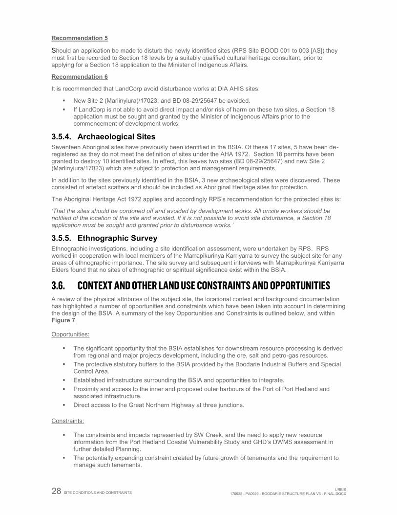
28 SITE CONDITIONS AND CONSTRAINTS URBIS170928 - PA0929 - BOODARIE STRUCTURE PLAN V5 - FINAL.DOCX
Recommendation 5
Should an application be made to disturb the newly identified sites (RPS Site BOOD 001 to 003 [AS]) they must first be recorded to Section 18 levels by a suitably qualified cultural heritage consultant, prior to applying for a Section 18 application to the Minister of Indigenous Affairs.
Recommendation 6
It is recommended that LandCorp avoid disturbance works at DIA AHIS sites:
New Site 2 (Marlinyiura)/17023; and BD 08-29/25647 be avoided. If LandCorp is not able to avoid direct impact and/or risk of harm on these two sites, a Section 18
application must be sought and granted by the Minister of Indigenous Affairs prior to the commencement of development works.
3.5.4. Archaeological Sites Seventeen Aboriginal sites have previously been identified in the BSIA. Of these 17 sites, 5 have been de-registered as they do not meet the definition of sites under the AHA 1972. Section 18 permits have been granted to destroy 10 identified sites. In effect, this leaves two sites (BD 08-29/25647) and new Site 2 (Marlinyiura/17023) which are subject to protection and management requirements.
In addition to the sites previously identified in the BSIA, 3 new archaeological sites were discovered. These consisted of artefact scatters and should be included as Aboriginal Heritage sites for protection.
The Aboriginal Heritage Act 1972 applies and accordingly RPS’s recommendation for the protected sites is:
‘That the sites should be cordoned off and avoided by development works. All onsite workers should be notified of the location of the site and avoided. If it is not possible to avoid site disturbance, a Section 18 application must be sought and granted prior to disturbance works.’
3.5.5. Ethnographic Survey Ethnographic investigations, including a site identification assessment, were undertaken by RPS. RPS worked in cooperation with local members of the Marrapikurinya Karriyarra to survey the subject site for any areas of ethnographic importance. The site survey and subsequent interviews with Marrapikurinya Karriyarra Elders found that no sites of ethnographic or spiritual significance exist within the BSIA.
3.6. CONTEXT AND OTHER LAND USE CONSTRAINTS AND OPPORTUNITIES A review of the physical attributes of the subject site, the locational context and background documentation has highlighted a number of opportunities and constraints which have been taken into account in determining the design of the BSIA. A summary of the key Opportunities and Constraints is outlined below, and within Figure 7. Opportunities:
The significant opportunity that the BSIA establishes for downstream resource processing is derived from regional and major projects development, including the ore, salt and petro-gas resources.
The protective statutory buffers to the BSIA provided by the Boodarie Industrial Buffers and Special Control Area.
Established infrastructure surrounding the BSIA and opportunities to integrate. Proximity and access to the inner and proposed outer harbours of the Port of Port Hedland and
associated infrastructure. Direct access to the Great Northern Highway at three junctions.
Constraints:
The constraints and impacts represented by SW Creek, and the need to apply new resource information from the Port Hedland Coastal Vulnerability Study and GHD’s DWMS assessment in further detailed Planning.
The potentially expanding constraint created by future growth of tenements and the requirement to manage such tenements.
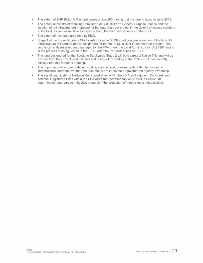
URBIS 170928 - PA0929 - BOODARIE STRUCTURE PLAN V5 - FINAL.DOCX
SITE CONDITIONS AND CONSTRAINTS 29
The extent of BHP Billiton’s Pastoral Lease on Lot 203, noting that it is due to lapse in June 2015. The potential constraint resulting from some of BHP Billiton’s General Purpose Leases and the
location of rail infrastructure proposed for the outer harbour project in the vicinity of access corridors to the Port, as well as multiple stockyards along the northern boundary of the BSIA.
The extent of the lease area held by FMG. Stage 1 of the future Boodarie Stockyards (Reserve 50892) part contains a section of the Roy Hill
Infrastructure rail corridor and is designated for the future Multi User Outer Harbour corridor. This land is currently reserved and managed by the PPA under the Land Administration Act 1997 and is in the process of being vested in the PPA under the Port Authorities Act 1999.
The land designated for the Boodarie Stockyards Stage 2 will be cleared of Native Title and will be excised from the current pastoral land and reserved for vesting in the PPA – PPA has recently advised that this matter is ongoing.
The importance of accommodating existing service corridor easements within future road or infrastructure corridors, whether the easements are in private or government agency ownership.
The significant cluster of Heritage Registered Sites within the BSIA and adjacent SW Creek and potential Registered Sites within the PPA (note the recommendation to seek a Section 18 determination and pursue mitigative research if the protection of these sites is not possible).
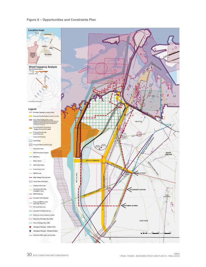
30 SITE CONDITIONS AND CONSTRAINTS URBIS170928 - PA0929 - BOODARIE STRUCTURE PLAN V5 - FINAL.DOCX
Figure 6 – Opportunities and Constraints Plan
URBIS 170928 - PA0929 - BOODARIE STRUCTURE PLAN V5 - FINAL.DOCX
DESIGN PHILOSOPHY, LAND USE AND SUBDIVISION/DEVELOPMENT
REQUIREMENTS 31
4. DESIGN PHILOSOPHY, LAND USE AND SUBDIVISION/DEVELOPMENT REQUIREMENTS
4.1. BOODARIE STRATEGIC INDUSTRIAL AREA – STRUCTURE PLAN
4.1.1. Vision The BSIA is positioned to accommodate strategic downstream resource processing industries related to the ore and petro-gas resources of the Pilbara region. The proximity of the BSIA to the Port has the potential to create a world-class heavy industrial estate which specialises in multi-product, downstream resource processing.
The location, connectivity and synergies between existing and future land uses associated with the BSIA highlight its position as a strategic long term heavy industrial development. These attributes further demonstrate the national significance of the BSIA in providing for the diversification of industry.
4.1.2. Objectives The preparation of the BSIA has been guided by the following objectives:
To provide a framework to guide coordinated development of the BSIA and future planning approvals in order to optimise capacity for strategic industrial use.
To provide industry with a comprehensive information pack, in the form of this structure plan and associated reports, to facilitate appropriate types and forms of development within the BSIA.
To establish specific infrastructure corridors that provide an essential link between the Port and the BSIA.
To establish Port capacity and access to enable optimal industrial development and export within the BSIA.
To facilitate development through the Planning Scheme and a structure plan process, coupled with an Estate Management and approvals structure.
4.1.3. Overview The establishment of heavy industry at Boodarie is inevitably linked to production and export that rely heavily on feedstocks including iron ore, oil and gas from the Pilbara and North West Shelf. Demand for land for industrial development will increase, fuelled in part by accelerating resource development activity in the Kimberley.
The land available at Boodarie can accommodate the increased resource processing and associated industries, but an efficient, carefully planned linkage to the Port is critical to allow its full capacity to be exploited. The infrastructure corridor between the Port and the industrial estate must accommodate:
Proponents’ servicing roads Movement of materials by pipelines and conveyors Movement of Pre-Assembled Modules (PAMs) to support the increased activity expected in the area
for transport of modular plant and building structures Power distribution and miscellaneous services
To ensure the full potential of the BSIA can be achieved, the design team have allocated land for corridors of sufficient width to accommodate the above requirements.
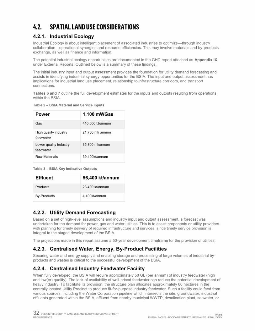
32 DESIGN PHILOSOPHY, LAND USE AND SUBDIVISION/DEVELOPMENT REQUIREMENTS URBIS
170928 - PA0929 - BOODARIE STRUCTURE PLAN V5 - FINAL.DOCX
4.2. SPATIAL LAND USE CONSIDERATIONS 4.2.1. Industrial Ecology Industrial Ecology is about intelligent placement of associated industries to optimize—through industry collaboration—operational synergies and resource efficiencies. This may involve materials and by-products exchange, as well as finance and information.
The potential industrial ecology opportunities are documented in the GHD report attached as Appendix IX under External Reports. Outlined below is a summary of these findings.
The initial industry input and output assessment provides the foundation for utility demand forecasting and assists in identifying industrial synergy opportunities for the BSIA. The input and output assessment has implications for industrial land use placement, relationship to infrastructure corridors, and transport connections.
Tables 6 and 7 outline the full development estimates for the inputs and outputs resulting from operations within the BSIA.
Table 2 – BSIA Material and Service Inputs
Power 1,100 mWGas
Gas 410,000 tJ/annum
High quality industry feedwater
21,700 ml/ annum
Lower quality industry feedwater
35,800 ml/annum
Raw Materials 39,400kt/annum
Table 3 – BSIA Key Indicative Outputs
Effluent 56,400 kt/annum
Products 23,400 kt/annum
By-Products 4,400kt/annum
4.2.2. Utility Demand Forecasting Based on a set of high-level assumptions and industry input and output assessment, a forecast was undertaken for the demand for power, gas and water utilities. This is to assist proponents or utility providers with planning for timely delivery of required infrastructure and services, since timely service provision is integral to the staged development of the BSIA.
The projections made in this report assume a 50-year development timeframe for the provision of utilities.
4.2.3. Centralised Water, Energy, By-Product Facilities Securing water and energy supply and enabling storage and processing of large volumes of industrial by-products and wastes is critical to the successful development of the BSIA.
4.2.4. Centralised Industry Feedwater Facility When fully developed, the BSIA will require approximately 58 GL (per annum) of industry feedwater (high and low(er) quality). The lack of availability of well-priced feedwater can reduce the potential development of heavy industry. To facilitate its provision, the structure plan allocates approximately 60 hectares in the centrally located Utility Precinct to produce fit-for-purpose industry feedwater. Such a facility could feed from various sources, including the Water Corporation pipeline which intersects the site, groundwater, industrial effluents generated within the BSIA, effluent from nearby municipal WWTP, desalination plant, seawater, or
URBIS 170928 - PA0929 - BOODARIE STRUCTURE PLAN V5 - FINAL.DOCX
DESIGN PHILOSOPHY, LAND USE AND SUBDIVISION/DEVELOPMENT
REQUIREMENTS 33
a combination of these sources. In order to future proof the provision of water within the BSIA, the structure plan assumes supply from variable water sources, allowing for the use of any of them as development progresses.
4.2.5. Centralised Energy Facility Given the potentially significant energy requirements of the BSIA, it is proposed to allocate about 60 hectares for the development of a new centralised and joint industry energy facility in the Utility Precinct. This will create economies of scale and avoid the need for multiple smaller and underutilised facilities throughout the BSIA. Such a facility could produce electricity, steam, and chilled and/or hot air for industries in its proximity. Allowance should be made for the facility to feed from various energy sources, including gas, coal, renewables, and industry waste heat. Co-location of the centralised energy facility and the industry feedwater facility is recommended to enable the generation of feedwater or seawater desalination with industry waste heat.
4.2.6. Centralised By-Product Facility Significant amounts of industrial by-products (both inorganic and organic) will likely be generated by operations within the BSIA. Rather than stockpiling large volume industrial by-products within the strategic core of the BSIA, there is potential to transfer them to a centralised storage facility in the southern part of the buffer zone. Such a centralised facility within the buffer would maximise industrial land use in the strategic core and could also facilitate the processing of industrial by-products into reusable materials.
4.2.7. Precincts and Industry Clustering The clustering of associated industries is at the heart of industrial ecology. Industry clustering is a critical element to allow for the development of synergies within the BSIA and the surrounding region, as well as a mechanism to optimise utility infrastructure and associated costs.
Industry clustering is facilitated through the designation of industry precincts and the placement of associated industries within them. Industry clustering options can be based on various parameters, such as water and energy consumption, risk profile, services and support, and processing of organic and/or inorganic materials. This assessment provides guidance on the types of industry clustering that can occur in the BSIA.
Based on the industry input and output assessment, previous research and reports, regional industrial synergies, and industry placement identified in the Industrial Ecology report, the Design Team located the industrial precincts within the BSIA according to the following criteria:
Port Dependent and Material Intensive Industries Downstream Iron Ore Processing Downstream Petroleum / Gas / Coal Processing Resource Processing Support industries By-product storage
The Precinct Plan is included as Figure 3.
4.3. INFRASTRUCTURE AND CORRIDOR CONSIDERATIONS The success of the BSIA largely depends on industry operational requirements and efficient access to the Port. This need for access in turn requires carefully considered infrastructure corridors. Without these, the full development of the BSIA will be difficult to realise. As previously mentioned, a Worley Parsons study was undertaken, providing recommendations to ensure infrastructure integration between the Port area and the BSIA. The results of this investigation were integral to preparation of the structure plan.
Outlined below are the key landuse considerations required to prepare a structure plan that can facilitate the effective and efficient development of the BSIA.
4.3.1. Industry Association to Port Based on the cross-correlation between the Industrial Ecology outcomes and the PPA’s Port Structure Plan, the relationship of the proposed industries to the Port is summarised in the following Table 4.
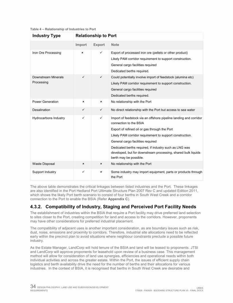
34 DESIGN PHILOSOPHY, LAND USE AND SUBDIVISION/DEVELOPMENT REQUIREMENTS URBIS
170928 - PA0929 - BOODARIE STRUCTURE PLAN V5 - FINAL.DOCX
Table 4 – Relationship of Industries to Port
Industry Type Relationship to Port
Import Export Note
Iron Ore Processing Export of processed iron ore (pellets or other product)
Likely PAM corridor requirement to support construction.
General cargo facilities required
Dedicated berths required.
Downstream Minerals Processing
Could potentially involve import of feedstock (alumina etc)
Likely PAM corridor requirement to support construction.
General cargo facilities required
Dedicated berths required.
Power Generation No relationship with the Port
Desalination No direct relationship with the Port but access to sea water
Hydrocarbons Industry Import of feedstock via an offshore pipeline landing and corridor connection to the BSIA
Export of refined oil or gas through the Port
Likely PAM corridor requirement to support construction.
General cargo facilities required
Dedicated berths required, if industry such as LNG was developed, but for downstream processing, shared bulk liquids berth may be possible.
Waste Disposal No relationship with the Port
Support Industry Some industry may import equipment, parts or products through the Port
The above table demonstrates the critical linkages between listed industries and the Port. These linkages are also identified in the Port Hedland Port Ultimate Structure Plan 2007 Rev C and updated Edition 2011, which shows the likely Port berth scenario to consist of four berths in South West Creek and a corridor connection to the Port to enable the BSIA (Refer Appendix C).
4.3.2. Compatibility of Industry, Staging and Perceived Port Facility Needs The establishment of industries within the BSIA that require a Port facility may drive preferred land selection to sites closer to the Port, creating competition for land and access to the corridors. However, proponents may have other considerations for preferred industrial placement.
The compatibility of adjacent uses is another important consideration, as are boundary issues such as risk, dust, noise, emissions and proximity to corridors. Therefore, industrial site allocations need to be reflected early within the precinct plan to avoid situations where neighbour constraints preclude a possible future industry.
As the Estate Manager, LandCorp will hold tenure of the BSIA and land will be leased to proponents. JTSI and LandCorp will approve proponents for leasehold upon review of a business case. This management method will allow for consideration of land use synergies, efficiencies and operational needs within both individual activities and across the greater estate. Within the Port, the issues of efficient supply chain logistics and berth availability drive the need for the number of berths and their allocations for various industries. In the context of BSIA, it is recognised that berths in South West Creek are desirable and
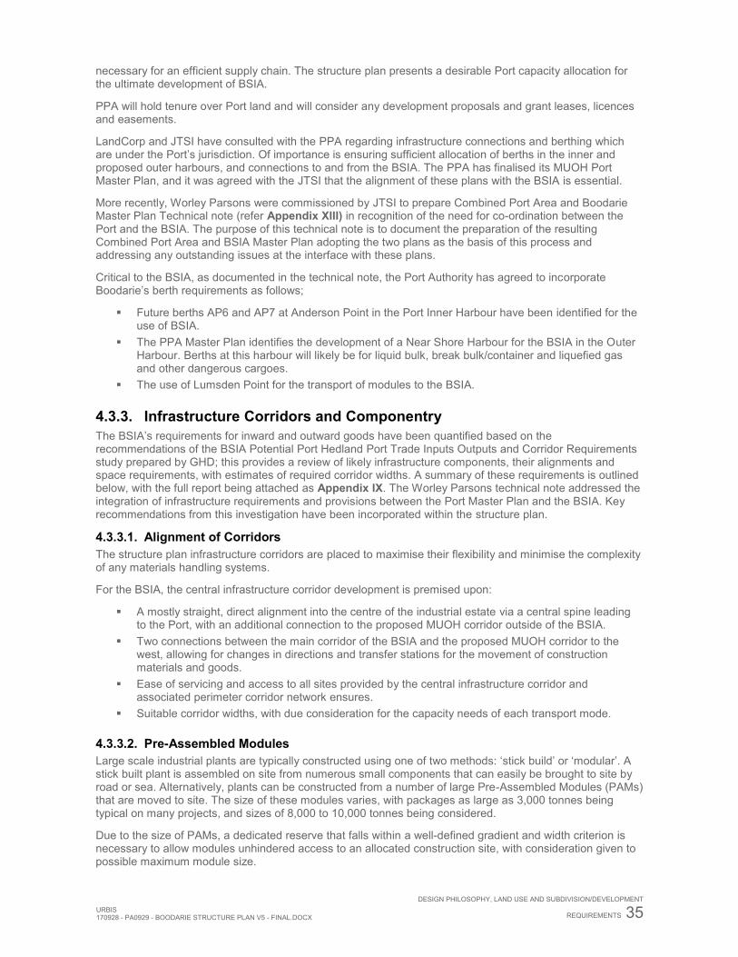
URBIS 170928 - PA0929 - BOODARIE STRUCTURE PLAN V5 - FINAL.DOCX
DESIGN PHILOSOPHY, LAND USE AND SUBDIVISION/DEVELOPMENT
REQUIREMENTS 35
necessary for an efficient supply chain. The structure plan presents a desirable Port capacity allocation for the ultimate development of BSIA.
PPA will hold tenure over Port land and will consider any development proposals and grant leases, licences and easements.
LandCorp and JTSI have consulted with the PPA regarding infrastructure connections and berthing which are under the Port’s jurisdiction. Of importance is ensuring sufficient allocation of berths in the inner and proposed outer harbours, and connections to and from the BSIA. The PPA has finalised its MUOH Port Master Plan, and it was agreed with the JTSI that the alignment of these plans with the BSIA is essential.
More recently, Worley Parsons were commissioned by JTSI to prepare Combined Port Area and Boodarie Master Plan Technical note (refer Appendix XIII) in recognition of the need for co-ordination between the Port and the BSIA. The purpose of this technical note is to document the preparation of the resulting Combined Port Area and BSIA Master Plan adopting the two plans as the basis of this process and addressing any outstanding issues at the interface with these plans.
Critical to the BSIA, as documented in the technical note, the Port Authority has agreed to incorporate Boodarie’s berth requirements as follows;
Future berths AP6 and AP7 at Anderson Point in the Port Inner Harbour have been identified for the use of BSIA.
The PPA Master Plan identifies the development of a Near Shore Harbour for the BSIA in the Outer Harbour. Berths at this harbour will likely be for liquid bulk, break bulk/container and liquefied gas and other dangerous cargoes.
The use of Lumsden Point for the transport of modules to the BSIA.
4.3.3. Infrastructure Corridors and Componentry The BSIA’s requirements for inward and outward goods have been quantified based on the recommendations of the BSIA Potential Port Hedland Port Trade Inputs Outputs and Corridor Requirements study prepared by GHD; this provides a review of likely infrastructure components, their alignments and space requirements, with estimates of required corridor widths. A summary of these requirements is outlined below, with the full report being attached as Appendix IX. The Worley Parsons technical note addressed the integration of infrastructure requirements and provisions between the Port Master Plan and the BSIA. Key recommendations from this investigation have been incorporated within the structure plan.
4.3.3.1. Alignment of Corridors The structure plan infrastructure corridors are placed to maximise their flexibility and minimise the complexity of any materials handling systems.
For the BSIA, the central infrastructure corridor development is premised upon:
A mostly straight, direct alignment into the centre of the industrial estate via a central spine leading to the Port, with an additional connection to the proposed MUOH corridor outside of the BSIA.
Two connections between the main corridor of the BSIA and the proposed MUOH corridor to the west, allowing for changes in directions and transfer stations for the movement of construction materials and goods.
Ease of servicing and access to all sites provided by the central infrastructure corridor and associated perimeter corridor network ensures.
Suitable corridor widths, with due consideration for the capacity needs of each transport mode.
4.3.3.2. Pre-Assembled Modules Large scale industrial plants are typically constructed using one of two methods: ‘stick build’ or ‘modular’. A stick built plant is assembled on site from numerous small components that can easily be brought to site by road or sea. Alternatively, plants can be constructed from a number of large Pre-Assembled Modules (PAMs) that are moved to site. The size of these modules varies, with packages as large as 3,000 tonnes being typical on many projects, and sizes of 8,000 to 10,000 tonnes being considered.
Due to the size of PAMs, a dedicated reserve that falls within a well-defined gradient and width criterion is necessary to allow modules unhindered access to an allocated construction site, with consideration given to possible maximum module size.
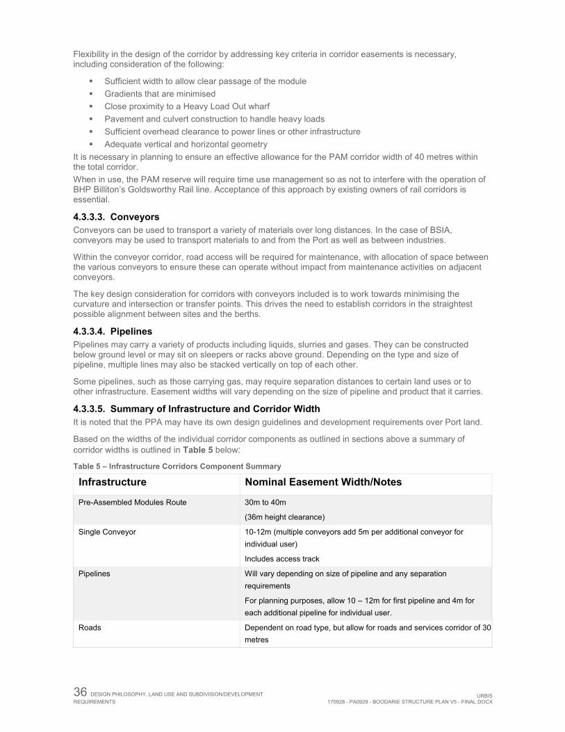
36 DESIGN PHILOSOPHY, LAND USE AND SUBDIVISION/DEVELOPMENT REQUIREMENTS URBIS
170928 - PA0929 - BOODARIE STRUCTURE PLAN V5 - FINAL.DOCX
Flexibility in the design of the corridor by addressing key criteria in corridor easements is necessary, including consideration of the following:
Sufficient width to allow clear passage of the module Gradients that are minimised Close proximity to a Heavy Load Out wharf Pavement and culvert construction to handle heavy loads Sufficient overhead clearance to power lines or other infrastructure Adequate vertical and horizontal geometry
It is necessary in planning to ensure an effective allowance for the PAM corridor width of 40 metres within the total corridor. When in use, the PAM reserve will require time use management so as not to interfere with the operation of BHP Billiton’s Goldsworthy Rail line. Acceptance of this approach by existing owners of rail corridors is essential.
4.3.3.3. Conveyors Conveyors can be used to transport a variety of materials over long distances. In the case of BSIA, conveyors may be used to transport materials to and from the Port as well as between industries.
Within the conveyor corridor, road access will be required for maintenance, with allocation of space between the various conveyors to ensure these can operate without impact from maintenance activities on adjacent conveyors.
The key design consideration for corridors with conveyors included is to work towards minimising the curvature and intersection or transfer points. This drives the need to establish corridors in the straightest possible alignment between sites and the berths.
4.3.3.4. Pipelines Pipelines may carry a variety of products including liquids, slurries and gases. They can be constructed below ground level or may sit on sleepers or racks above ground. Depending on the type and size of pipeline, multiple lines may also be stacked vertically on top of each other.
Some pipelines, such as those carrying gas, may require separation distances to certain land uses or to other infrastructure. Easement widths will vary depending on the size of pipeline and product that it carries.
4.3.3.5. Summary of Infrastructure and Corridor Width It is noted that the PPA may have its own design guidelines and development requirements over Port land.
Based on the widths of the individual corridor components as outlined in sections above a summary of corridor widths is outlined in Table 5 below:
Table 5 – Infrastructure Corridors Component Summary
Infrastructure Nominal Easement Width/Notes
Pre-Assembled Modules Route 30m to 40m
(36m height clearance)
Single Conveyor 10-12m (multiple conveyors add 5m per additional conveyor for individual user)
Includes access track
Pipelines Will vary depending on size of pipeline and any separation requirements
For planning purposes, allow 10 – 12m for first pipeline and 4m for each additional pipeline for individual user.
Roads Dependent on road type, but allow for roads and services corridor of 30 metres
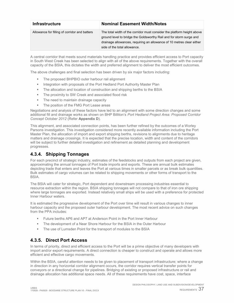
URBIS 170928 - PA0929 - BOODARIE STRUCTURE PLAN V5 - FINAL.DOCX
DESIGN PHILOSOPHY, LAND USE AND SUBDIVISION/DEVELOPMENT
REQUIREMENTS 37
Infrastructure Nominal Easement Width/Notes
Allowance for filling of corridor and batters The total width of the corridor must consider the platform height above ground level to bridge the Goldsworthy Rail and for storm surge and drainage allowances, requiring an allowance of 10 metres clear either side of the total allowance.
A central corridor that meets sound materials handling practice and provides efficient access to Port capacity in South West Creek has been selected to align with all of the above requirements. Together with the overall capacity of the BSIA, this dictates the width and preferred alignment to deliver the most efficient outcomes.
The above challenges and final selection has been driven by six major factors including:
The proposed BHPBIO outer harbour rail alignment Integration with proposals of the Port Hedland Port Authority Master Plan The allocation and location of construction and shipping berths to the BSIA The proximity to SW Creek and associated flood risk The need to maintain drainage capacity The position of the FMG Port Lease areas
Negotiations and analysis of these factors have led to an alignment with some direction changes and some additional fill and drainage works as shown on BHP Billiton’s Port Hedland Project Area: Proposed Corridor Concept October 2012 (Refer Appendix D).
This alignment, and associated connection points, has been further refined by the outcomes of a Worley Parsons investigation. This investigation considered more recently available information including the Port Master Plan, the allocation of import and export shipping berths, revisions to alignments due to heritage matters and drainage crossings. It is expected that the precise location, width and content of the corridors will be subject to further detailed investigation and refinement as detailed planning and development progresses.
4.3.4. Shipping Tonnages For each precinct of strategic industry, estimates of the feedstocks and outputs from each project are given, approximating the annual tonnages of Port trade imports and exports. These are annual bulk estimates depicting trade that enters and leaves the Port at various times in smaller parcels or as break bulk quantities. Bulk estimates of cargo volumes can be related to shipping movements or other forms of transport to the BSIA.
The BSIA will cater for strategic, Port dependent and downstream processing industries essential to resource extraction within the region. BSIA shipping tonnages will not compare to that of iron ore shipping where large tonnages are exported. Instead relatively small ships will be used with a preference for protected Inner Harbour waters.
It is estimated the progressive development of the Port over time will result in various changes to inner harbour capacity and the proposed outer harbour development. The most recent advice on such changes from the PPA includes:
Future berths AP6 and AP7 at Anderson Point in the Port Inner Harbour The development of a Near Shore Harbour for the BSIA in the Outer Harbour The use of Lumsden Point for the transport of modules to the BSIA
4.3.5. Direct Port Access In terms of priority, direct and efficient access to the Port will be a prime objective of many developers with import and/or export requirements. A direct connection is cheaper to construct and operate and allows more efficient and effective cargo movements.
Within the BSIA, careful attention needs to be given to placement of transport infrastructure; where a change in direction in any horizontal corridor alignment occurs, the corridor requires vertical transfer points for conveyors or a directional change for pipelines. Bridging of existing or proposed infrastructure or rail and drainage allocation has additional space needs. All of these requirements have cost, space, interface
38 DESIGN PHILOSOPHY, LAND USE AND SUBDIVISION/DEVELOPMENT REQUIREMENTS URBIS
170928 - PA0929 - BOODARIE STRUCTURE PLAN V5 - FINAL.DOCX
management and timing implications to be resolved each time an installation of additional corridor infrastructure occurs.
The most direct Port access is via the proposed central infrastructure corridor with secondary and less direct connection being provided by a road link to the east to Lumsden Point berths. Infrastructure corridor connections are also provided on an east-west alignment connecting the central corridor within the BSIA and the outer harbour infrastructure corridor to the west.
4.4. INDUSTRIAL SEPARATION Consideration of separation distances between incompatible and sensitive land uses is a key aspect in providing for the operation of anticipated uses within the BSIA.
In order to determine appropriate separation distances, location of precincts and indicative development options, a series of emission assessments including acoustic, quantitative risk, and air quality have been taken into account. These studies are summarised below, with full reports being located within the Appendices under External Reports.
4.4.1. Acoustic Assessment Herring Storer Acoustics developed an acoustic model to predict noise emissions from the proposed BSIA. The report, titled Boodarie Industrial Estate South Hedland Environmental Noise Assessment, is summarised below, with the full report attached at Appendix X.
The acoustic assessment shows allowable maximum sound power levels applicable to each industry if the BSIA was filled to capacity with a range of industries. The modelling demonstrates that a wide range of noise producing developments can be accommodated within the BSIA.
While the overall combined noise emissions from the BSIA would exceed the assigned LA10 night time noise level of 35 dB(A) at the boundary of the buffer. Compliance with the Regulations would still be achieved (as shown in Herring Storer Acoustics Appendix C of Appendix X, Figure C2), with noise emissions from individual industries complying with the ‘significantly contributing’ requirements of the Regulations2. In order to demonstrate compliance, noise emissions from each industry, when received at the boundary of the buffer zone, need to achieve an LA10 noise level of 30 dB(A), 5 dB below the assigned LA10 night time noise level.
While acoustic modelling indicates that the current BSIA buffer will provide suitable protection to surrounding noise sensitive premises, consideration of the required distances between industries and neighbouring industry premise boundaries will be needed during structure planning stages should the locations and operations of uses differ from those anticipated. The compliance with noise levels will require individual developments to provide mitigating works and/or strategies at the cost of the proponents.
4.4.2. Air Quality Assessment The BSIA Air Quality Report prepared by Air Assessments (August 2012) describes a review of the adequacy of the BSIA buffer for the management of air quality impacts from future industries. The findings of the report are summarised below, with the full report attached at Appendix XI.
The methodology used dispersion modelling based on estimated air emissions and typical annual meteorology to predict ambient concentrations for comparison to criteria for acceptable impacts outside the buffer.
Dust (as PM10) and NOx as NO2 are two air emissions common to the type of industrial developments anticipated for the BSIA and as such were considered –
Dust (as PM10) from low level sources For dust assessments in the state, generally the DWER assess predicted levels (including background levels) against the NEPM PM10 criterion of a 24-hour average standard of 50 μg/m3, not to be exceeded more than 5 times per year. For the Port Hedland region however, this is impractical since the criterion is
2 For the purposes of subregulation (1) (a), a noise emission is taken to ‘significantly contribute to’ a level of noise if the noise emission
as determined under subregulation (3) exceeds a value which is 5 dB below the assigned level at the point of reception.
URBIS 170928 - PA0929 - BOODARIE STRUCTURE PLAN V5 - FINAL.DOCX
DESIGN PHILOSOPHY, LAND USE AND SUBDIVISION/DEVELOPMENT
REQUIREMENTS 39
often exceeded due to background dust contributions alone (Note: exceedances due to background dust were 6 for the modelled year). Modelling with the background dust and the existing developments at Port Hedland, indicates that the number of exceedances would be 10 at Wedgefield, 7 at South Hedland and 6 at Bosna.
Modelling in this study including the proposed full iron ore handling development scenario (which is outside the BSIA) and existing and background dust sources, indicated that the number of exceedances of the NEPM PM10 standard would increase to 18 at Wedgefield, 10 at South Hedland and 10 at Bosna. This modelling did not include dust due to the potential processing plant stack emissions as they are relatively minor compared to dust off their stockpile areas and has negligible impact.
Instead of the NEPM standard, the Port Hedland Dust Management Taskforce (Government of WA, 2010) adopted in March 2010 an interim (5 year) guideline measure for PM10 concentrations of 70 μg/m3 (24 hour average) with 10 exceedances per calendar year. This was for the area east of Taplin Street in Port Hedland. This criterion was based on advice from expert toxicologists that the NEPM PM10 standard was designed for an urban setting and never intended for iron ore dust. Modelling with the proposed full development scenario, together with existing and background dust, indicated that the number of exceedances of this criterion would increase from 2 to 3 at Wedgefield, from 1 to 2 at South Hedland and remain at 1 (due to background sources) at Bosna. These are all well below the criterion level of 10.
Notwithstanding the adequacy of the buffer to accommodate any dust issues, proponents should be required to propose appropriate mitigation techniques to reduce the potential of any dust issues.
NOx/NO2 from elevated sources Two industrial development scenarios for process industries were considered:
One consisting of seven gas feedstock processing industries A more intensive scenario consisting of ten heavy industries used as a noise impact assessment
scenario In both cases, the buffer is more than adequate for the dispersion of NO2 emissions required to meet ambient standards.
4.4.3. Quantitative Risk Assessment A Quantitative Risk Assessment (QRA) was undertaken by GHD in order to determine if the existing Special Control Area Buffer was adequate, and to ensure the BSIA and individual industries could be developed to their full potential. The findings of the Report for Boodarie Strategic Industrial Area: Concept Plan Quantitative Risk Assessment (July 2012) are summarised below, with the full report attached at Appendix XII.
Based on the indicative industry locations outlined within the Industrial Ecology Study, the QRA reviewed the risks associated with the locations of user groups in the BSIA. Seven (7) Major Risk Generators (MRG) were identified – being: Chlor-Alkali, Ammonia, Ethane Extraction, Titanium, Sodium Cyanide, Methanol and Ethylene Dichloride. The QRA reviewed the risks associated with these in order to confirm that cumulative risks generated could be contained within the buffer, and individual risk on site.
The QRA determined that the proposed buffer zone was adequate for the risk generated by the proposed user groups.
4.4.4. Spatial Land Use Considerations Summary There are a number of factors that must be considered when developing a suitable layout for large scale industrial uses. Through the background investigations, technical reports and concept design layout options, the following factors, as outlined in Table 10, have been taken into account in the preparation of the structure plan.
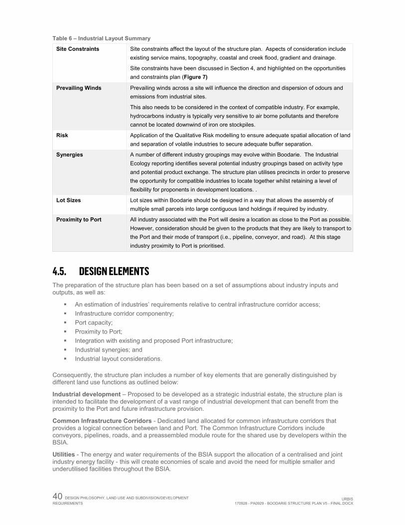
40 DESIGN PHILOSOPHY, LAND USE AND SUBDIVISION/DEVELOPMENT REQUIREMENTS URBIS
170928 - PA0929 - BOODARIE STRUCTURE PLAN V5 - FINAL.DOCX
Table 6 – Industrial Layout Summary
Site Constraints Site constraints affect the layout of the structure plan. Aspects of consideration include existing service mains, topography, coastal and creek flood, gradient and drainage.
Site constraints have been discussed in Section 4, and highlighted on the opportunities and constraints plan (Figure 7)
Prevailing Winds Prevailing winds across a site will influence the direction and dispersion of odours and emissions from industrial sites.
This also needs to be considered in the context of compatible industry. For example, hydrocarbons industry is typically very sensitive to air borne pollutants and therefore cannot be located downwind of iron ore stockpiles.
Risk Application of the Qualitative Risk modelling to ensure adequate spatial allocation of land and separation of volatile industries to secure adequate buffer separation.
Synergies A number of different industry groupings may evolve within Boodarie. The Industrial Ecology reporting identifies several potential industry groupings based on activity type and potential product exchange. The structure plan utilises precincts in order to preserve the opportunity for compatible industries to locate together whilst retaining a level of flexibility for proponents in development locations. .
Lot Sizes Lot sizes within Boodarie should be designed in a way that allows the assembly of multiple small parcels into large contiguous land holdings if required by industry.
Proximity to Port All industry associated with the Port will desire a location as close to the Port as possible. However, consideration should be given to the products that they are likely to transport to the Port and their mode of transport (i.e., pipeline, conveyor, and road). At this stage industry proximity to Port is prioritised.
4.5. DESIGN ELEMENTS The preparation of the structure plan has been based on a set of assumptions about industry inputs and outputs, as well as:
An estimation of industries’ requirements relative to central infrastructure corridor access; Infrastructure corridor componentry; Port capacity; Proximity to Port; Integration with existing and proposed Port infrastructure; Industrial synergies; and Industrial layout considerations.
Consequently, the structure plan includes a number of key elements that are generally distinguished by different land use functions as outlined below:
Industrial development – Proposed to be developed as a strategic industrial estate, the structure plan is intended to facilitate the development of a vast range of industrial development that can benefit from the proximity to the Port and future infrastructure provision.
Common Infrastructure Corridors - Dedicated land allocated for common infrastructure corridors that provides a logical connection between land and Port. The Common Infrastructure Corridors include conveyors, pipelines, roads, and a preassembled module route for the shared use by developers within the BSIA.
Utilities - The energy and water requirements of the BSIA support the allocation of a centralised and joint industry energy facility - this will create economies of scale and avoid the need for multiple smaller and underutilised facilities throughout the BSIA.
URBIS 170928 - PA0929 - BOODARIE STRUCTURE PLAN V5 - FINAL.DOCX
DESIGN PHILOSOPHY, LAND USE AND SUBDIVISION/DEVELOPMENT
REQUIREMENTS 41
External influences and opportunities – Whilst not included within the boundary of the structure plan, there are a number of externalities that either influence the industrial design within the structure plan or are required to support Development:
By-Product Storage - Significant amounts of industrial by-products (both inorganic and organic) will likely be generated by operations within the BSIA. It is intended that the stockpiling of the industrial by-products will occur in a centralised storage facility in the southern part of the buffer zone.
Multi User Outer Harbour CIC – PPA has designated a corridor to the west of BSIA which is referred to as the MUOH Corridor. The alignment of the MUOH Corridor will be finalised after detailed environmental, heritage and engineering studies have been undertaken. Whilst outside of the boundary of the structure plan, this is an important future corridor connection from the BSIA to both the BSIA Near Shore Harbour and the Outer Harbour and allows for public and private access roads, services easements, pipelines and conveyors.
Sand Ridge - The BSIA is currently afforded flood protection by the sand ridge adjacent to the Turner River. The 100 year ARI flood levels are contained within the low lying valley between Turner River flood plain east bank and the sand ridge. A level of protection has been afforded to the Turner River via the proposed amendment in order to ensure this level of protection remains and the operations of the BSIA are not compromised.
4.6. ESTATE DESIGN The BSIA Structure Plan, (Figure 2) reflects a site responsive approach that gives full consideration to environmental quality, while responding to industrial operational needs and providing for the development of diversified industry.
The final lot layouts will be proponent driven and will evolve over time in accordance with the placement of infrastructure within corridors and layout of respective Precincts outlined within the structure plan.
A transitional industrial placement model has been incorporated into the following locational criteria:
The relationship of industrial land use to the Port is prioritised from downstream minerals processing, iron ore processing, then hydrocarbons and other industries, noting the central location of the energy precinct.
When prioritising industrial Port location, consideration has been given to the nature of products transported and proximity to that transportation,
Proximity to the common infrastructure corridors that provides a logical connection between land and Port. The Common Infrastructure Corridors include conveyors, pipelines, roads, and a preassembled module route for the shared use by developers within the BSIA.
Prevailing winds influence the dispersion of emissions and therefore with QRA input, more volatile industries have been placed west or central within the BSIA.
Preserve the opportunity for a transition of industrial uses to achieve compatible industrial location. Design of industrial precincts to allow multiple small parcels to be assembled into large contiguous
land holdings. The Coastal Vulnerability Study assessment and recent water management strategies. Hazardous industrial uses warranting separation from sensitive uses, are located toward the core of
the BSIA. Volatile Industries are proposed on the western margins of the Boodarie Strategic Industrial Area
with adequate separation from adjoining volatile industries (these industries are to satisfy the requirements of Section 7.0 of the Planning Scheme).
Less Hazardous industries are proposed on the eastern margins of the BSIA including support industries warranting high levels of access, which are placed adjacent to the Great Northern Highway.
Support industries to be located in precincts adjacent the Great Northern Highway. By-product storage areas derived from BSIA industries are located outside the BSIA Strategic
Industrial Zone with proximity to the Central Infrastructure Corridor.
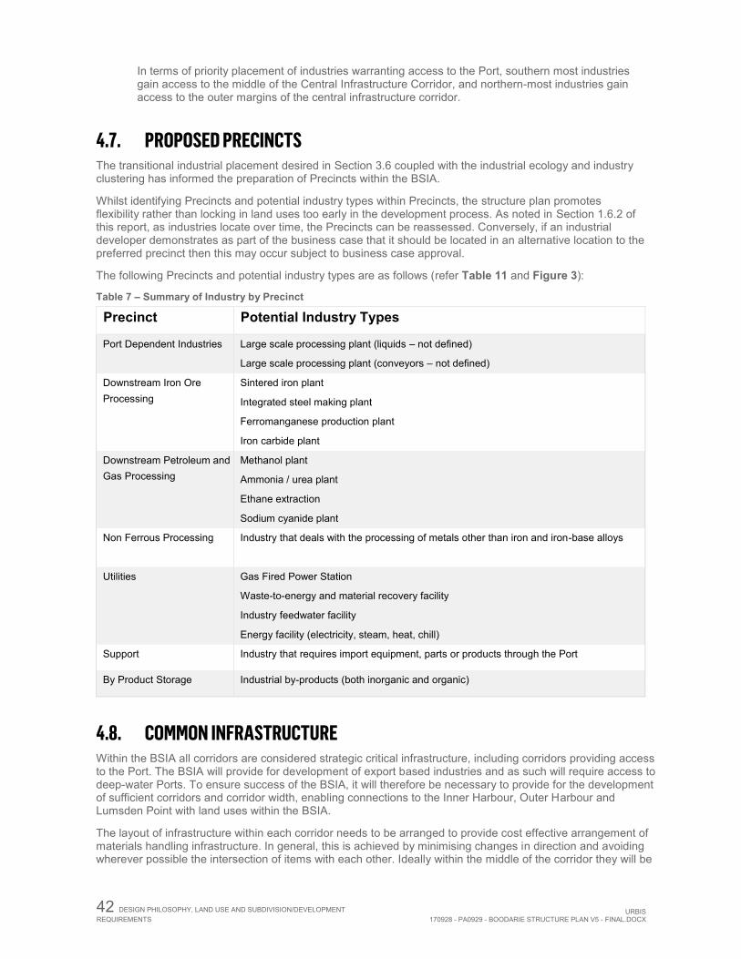
42 DESIGN PHILOSOPHY, LAND USE AND SUBDIVISION/DEVELOPMENT REQUIREMENTS URBIS
170928 - PA0929 - BOODARIE STRUCTURE PLAN V5 - FINAL.DOCX
In terms of priority placement of industries warranting access to the Port, southern most industries gain access to the middle of the Central Infrastructure Corridor, and northern-most industries gain access to the outer margins of the central infrastructure corridor.
4.7. PROPOSED PRECINCTS The transitional industrial placement desired in Section 3.6 coupled with the industrial ecology and industry clustering has informed the preparation of Precincts within the BSIA.
Whilst identifying Precincts and potential industry types within Precincts, the structure plan promotes flexibility rather than locking in land uses too early in the development process. As noted in Section 1.6.2 of this report, as industries locate over time, the Precincts can be reassessed. Conversely, if an industrial developer demonstrates as part of the business case that it should be located in an alternative location to the preferred precinct then this may occur subject to business case approval.
The following Precincts and potential industry types are as follows (refer Table 11 and Figure 3):
Table 7 – Summary of Industry by Precinct
Precinct Potential Industry Types
Port Dependent Industries Large scale processing plant (liquids – not defined)
Large scale processing plant (conveyors – not defined)
Downstream Iron Ore Processing
Sintered iron plant
Integrated steel making plant
Ferromanganese production plant
Iron carbide plant
Downstream Petroleum and Gas Processing
Methanol plant
Ammonia / urea plant
Ethane extraction
Sodium cyanide plant
Non Ferrous Processing
Industry that deals with the processing of metals other than iron and iron-base alloys
Utilities Gas Fired Power Station
Waste-to-energy and material recovery facility
Industry feedwater facility
Energy facility (electricity, steam, heat, chill)
Support Industry that requires import equipment, parts or products through the Port
By Product Storage Industrial by-products (both inorganic and organic)
4.8. COMMON INFRASTRUCTURE Within the BSIA all corridors are considered strategic critical infrastructure, including corridors providing access to the Port. The BSIA will provide for development of export based industries and as such will require access to deep-water Ports. To ensure success of the BSIA, it will therefore be necessary to provide for the development of sufficient corridors and corridor width, enabling connections to the Inner Harbour, Outer Harbour and Lumsden Point with land uses within the BSIA.
The layout of infrastructure within each corridor needs to be arranged to provide cost effective arrangement of materials handling infrastructure. In general, this is achieved by minimising changes in direction and avoiding wherever possible the intersection of items with each other. Ideally within the middle of the corridor they will be
URBIS 170928 - PA0929 - BOODARIE STRUCTURE PLAN V5 - FINAL.DOCX
DESIGN PHILOSOPHY, LAND USE AND SUBDIVISION/DEVELOPMENT
REQUIREMENTS 43
sequenced to accommodate the logical alignments with berth locations which are suited to particular ship types and loading systems. In this regard, preliminary planning has been undertaken for the corridors to assess the space required and the necessary operating and installation infrastructure necessary for a viable corridor alignment. Subject to the staging of development of the BSIA, the sequencing will be confirmed and will be subject to design at the development stage.
The location and design of the Common Infrastructure Corridors is based on:
Provision of sufficient land for infrastructure corridors connecting industries to each other and to transportation hubs like the Port.
The most critical infrastructure corridors will be those providing access to the Port from the BSIA - accordingly corridor width and straight alignment is critical.
The allocation of shipping berths to the BSIA, guiding the location of transport for imports, exports and construction materials.
Applying the key criteria for PAM Reserves including width, pavement for heavy loads, overhead clearance, and adequate vertical and horizontal geometry.
Placement of infrastructure within the corridor is sequenced so that those furthest from the Port occupy the central infrastructure corridor with those closest to the Port occupying the edge to minimise infrastructure crossing.
Ensuring a straight corridor for conveyors to minimise the number of transfer stations. Consideration of some pipeline separation requirements, such as those carrying gas, otherwise a
degree of flexibility in the placement exists. Enabling the exchange of materials between industries within the BSIA. Design of intersections and carriageways within the BSIA to accommodate the turning movements of
quad road trains. The structure plan includes key infrastructure corridors (being the main north-south Central and Western corridors) and two east-west corridors intersecting with main central corridor and providing an efficient connection to the outer harbour corridor to the west. Most of the outer harbour corridor is located outside of the BSIA, except for a small portion which enters the structure plan area to the northwest. The inclusion of the north south and east west corridors is driven by the location of berths as provided for by PPA in the Port Hedland Port Master Plan. The common infrastructure corridors are illustrated within Figure 8 as follows;
Central CIC - The central infrastructure corridor requirement, including the PAM and road requirements, is 300 metres. When allowance is made for the finished corridor levels, including line, grade separation of the Goldsworthy Rail, batters and drainage, an allowance of at least 300 metres gross width in plan form is considered appropriate, since batters to the central infrastructure corridor alone require significant space.
Central Diversion CIC - The 300m Infrastructure Corridor diverts into two corridors in the vicinity of the Goldsworthy Rail. The first of these corridors is proposed to be 200m wide and travels along the same alignment as the original 300m corridor towards the inner harbour. The second corridor is 120m wide and travels west initially before rerouting in a northbound direction and joining the Multi User Outer Harbour Corridor.
West CIC - Feeding into the central infrastructure corridor, the west CIC has been reduced to an allowance of 100 metres on the basis that it is in the southern portion of the BSIA and is likely to service a smaller number of industrial entities. This corridor will only be provided if and when it is required and has therefore been nominated as an indicative corridor location.
North CIC – Initial designs indicated the need for a northern infrastructure corridor of 100m in width on a north-west/south-east alignment. This corridor would have connected the central corridor with the outer harbour corridor. The north CIC has been deleted and replaced with a direct east-west corridor linking the central corridor and a relocated outer harbour corridor. Due to this alignment, servicing additional industrial land and having a direct connection, its width has been increased to approximately 200m.
Multi User Outer Harbour CIC – As noted in Section 3.5 above, PPA has designated a corridor to the west of BSIA which is referred to as the MUOH Corridor. Whilst outside of the boundary of the structure plan, this is an important future corridor connection from the BSIA to both the BSIA Near Shore Harbour and the Outer Harbour and allows for public and private access roads, services easements, pipelines and conveyors. Given its future importance, the MUOH Corridor is identified on the structure plan for context purposes.
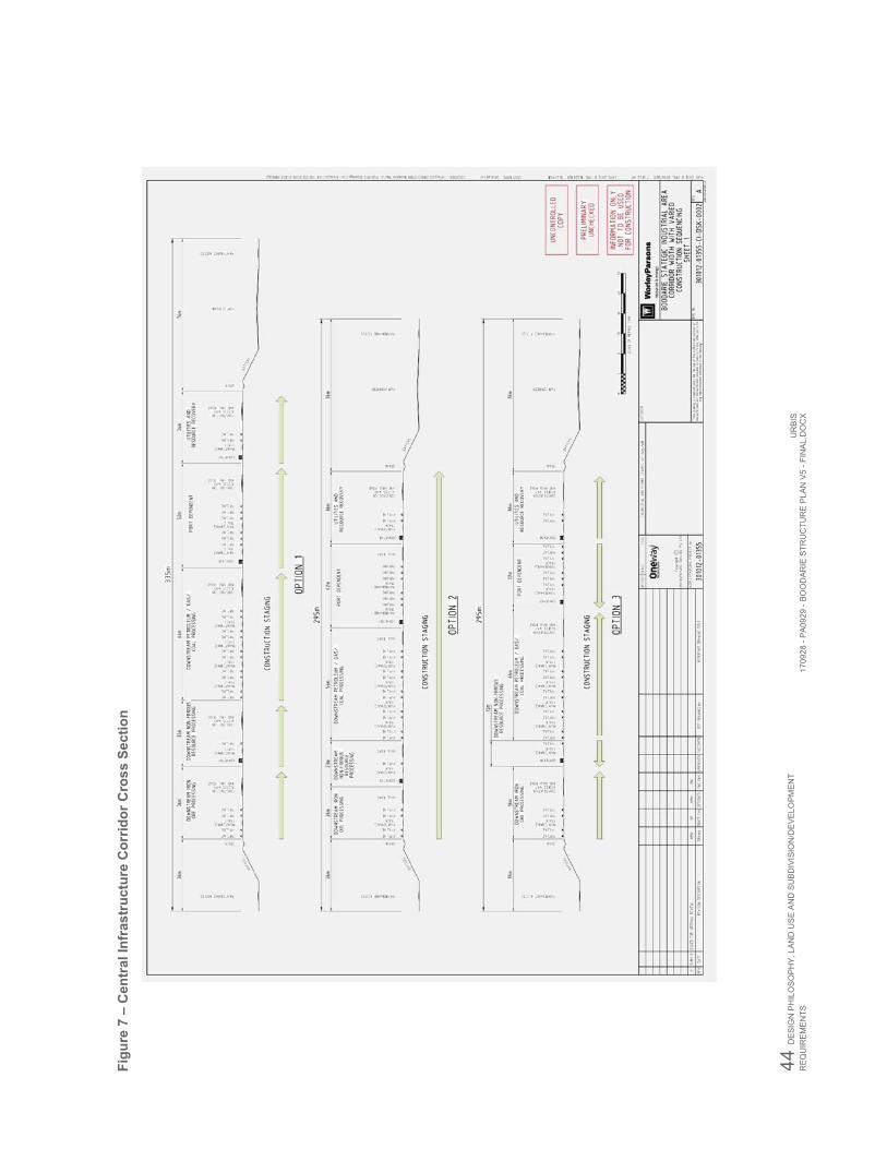
44 DE
SIG
N P
HIL
OSO
PHY,
LAN
D U
SE
AN
D S
UBD
IVIS
ION
/DEV
ELO
PMEN
T R
EQU
IREM
ENTS
U
RBI
S17
0928
- PA
0929
- BO
OD
ARIE
STR
UC
TUR
E PL
AN V
5 - F
INAL
.DO
CX
Figu
re 7
– C
entr
al In
fras
truc
ture
Cor
ridor
Cro
ss S
ectio
n

URBIS 170928 - PA0929 - BOODARIE STRUCTURE PLAN V5 - FINAL.DOCX
DESIGN PHILOSOPHY, LAND USE AND SUBDIVISION/DEVELOPMENT
REQUIREMENTS 45
4.9. PORT CAPACITY AND ACCESS The industrial ecology outcomes highlighted within the BSIA Industrial Ecology Report for the ultimate development of the BSIA provide the basis of the assessment of demand for Port facilities. In particular, likely industries in the BSIA include those that can be characterised as Port users with the following needs:
Typically utilise panamax size ships or smaller for the majority of trade; Are not tidally constrained as for Iron Ore vessels; Are engaged in bulk liquids and dry bulk trade; Require dedicated berths to maintain their supply chain reliability and throughput; and Will have direct linkage via the corridor to the industrial estate.
These criteria are the basis for allocating the berths required for each user, assuming where possible multi-user facilities, and where necessary, dedicated berths.
From the industrial ecology outcomes, as supported by LandCorp and JTSI, the multi-user berth requirement can be summarised as follows:
1 Bulk Liquids berth; 2 Dry Bulk berths; and 1 heavy load out facility to meet PAM requirements.
A range of vessel sizes is applied to estimate future berth requirements at the Port. While the individual berth capacity will not always be fully utilised due to freight logistics, these assumptions provide the guidance needed to plan for the long-term development of the BSIA.
Based on the mix of industries in the scenario proposed by GHD a total of 3 to 4 berths are required. Should the means of import/export into BSIA change, this will also influence the number of berths required.
Further, a Special Purpose Mooring (SPM) or possibly a berth for bulk liquid feedstocks such as oil and gas may be required.
The need to provide a corridor to the Outer Harbour is highlighted through the needs analysis.
Further clarity on this matter is provided within the Worley Parsons Combined Port Area and Boodarie Master Plan Technical note (refer Appendix XIII).
Berth availability – Given the magnitude of the iron ore industry in the Pilbara region, berth availability is limited within Port Hedland. The original intent was that up to four berths would be made available within South West Creek for BSIA use including the export of product and import of feedstock. The significant growth in the iron ore export potential within the Pilbara region has seen this allocated capacity reduced to two berths and the need for outer harbour capacity to supplement this need.
Future berths AP6 and AP7 at Anderson Point have been identified for the use of BSIA. This berth capacity is necessary in order to allow throughput for products destined for and originating for the BSIA. It is also important that the land backing and supporting these berths to accommodate corridor alignments and berth approaches also be secured to support the product handling and module load out requirements.
BSIA Near Shore Harbour – While bulk products can be handled on exposed offshore berths in the outer harbour, PPA has considered protected harbour basin solutions as many unit cargoes and bulk liquids may require a more protected berth than what is available in exposed conditions.
The PPA Master Plan identifies the development of a Near Shore Harbour for BSIA in the Outer Harbour. Berths at this harbour would be for liquid bulk, break bulk/container and liquefied gas and other dangerous cargoes. It should be noted that the BSIA Near Shore Harbour would require significant funding to develop and may be difficult to justify in a Phase 1 development for smaller projects. As such, whilst its development possibility must be secured to align with the full development potential of the BSIA, any first proponent who might also be required to develop other enabling infrastructure might benefit from an inner harbour berth where development costs for Port facilities might help shed some of the establishment costs at the BSIA. This further reinforces the need to ensure that berths AP6 and AP7 are reserved for the use of BSIA, and in parallel secure the proposed outer harbour to secure the future development potential.
46 DESIGN PHILOSOPHY, LAND USE AND SUBDIVISION/DEVELOPMENT REQUIREMENTS URBIS
170928 - PA0929 - BOODARIE STRUCTURE PLAN V5 - FINAL.DOCX
Lumsden Point – This location was investigated as a potential option for the transport of modules to the BSIA. The proposal is that modules of the scale of up to 5,000 tonnes may need to be moved from a berth to the BSIA. This places significant constraints on the alignment and grade of the proposed haul road alignment. In fact, the preference to keep such large packages outside of general public traffic and the complexity of moving such large items over long distances on public roads including Great Northern Highway limits the applicability of Lumsden Point to bulk construction materials and pieces of smaller size.
Berths AP6 and AP7 at Anderson Point are considered to be the best workable solution for large module transport working with a Lumsden facility for the bulk of other construction materials. The two facilities will work hand in hand to support the construction effort and volumes of materials to be moved. It should also be noted that the facilities at Berth AP6 and AP7 would best be considered as a versatile design which can support module load out along with product handling. The configuration of the materials handling on the berths was not considered in detail.
4.10. MOVEMENT NETWORK The BSIA Traffic Assessment was undertaken by GHD in April 2013. A summary of these requirements is outlined below and illustrated within Figure 9, with the full report being attached as Appendix II. 4.10.1. Traffic Generation Traffic generation was estimated by an analysis of:
The purpose, geography and layout of the planned industrial estate The materials input and output analysis derived from the industrial ecology scenario and associated
haulage estimates Expected employee numbers Bus transfers Individual daily trips
The traffic analysis considered the full development to 2031, in addition to interim development. Intersection treatments to the three main access points into the BSIA from Great Northern Highway (GNH) were integral to the assessment. 4.10.2. Forecast Traffic Volumes at Intersections with GNH The structure plan provides for three main access points from to the BSIA from GNH. These access points will ultimately provide appropriate levels of accessibility to the development. The location of these access points has been based on:
Separation distances that allow for sufficient merging Future grade separated interchanges Posted speed limits of 110 km/h Recommendations from Main Roads
The report has noted that if access to the Port is not available via the BSIA central infrastructure corridor then there will be additional haulage impacts to the three main proposed intersections with GNH. 4.10.3. Internal Roads and Intersection Controls The preferred internal road hierarchy and forecast traffic volumes on key roads are identified in GHD’s report. The forecast traffic volumes on the access roads connecting to GNH are estimated at 1,350 to 3,050vpd. This indicates that a single carriageway is likely to accommodate the BSIA development traffic with no anticipated capacity issues. In view of the road train activity accessing the BSIA, the three main access roads from GNH should accommodate right turn facilities to allow following traffic to pass. Internal intersections with the main access roads that connect with the Great Northern Highway should be channelised to include right and left turn

URBIS 170928 - PA0929 - BOODARIE STRUCTURE PLAN V5 - FINAL.DOCX
DESIGN PHILOSOPHY, LAND USE AND SUBDIVISION/DEVELOPMENT
REQUIREMENTS 47
lanes on the access roads. The cross section of access roads should comprise an overall reserve width of 35.2m consisting of: 2 x 5.1m verge, 2 x 5m traffic lane, 15m median with turn lanes where required. This excludes servicing requirements. It is considered that all other internal road pavements should be 10m wide within a 25m reserve excluding necessary servicing requirements.
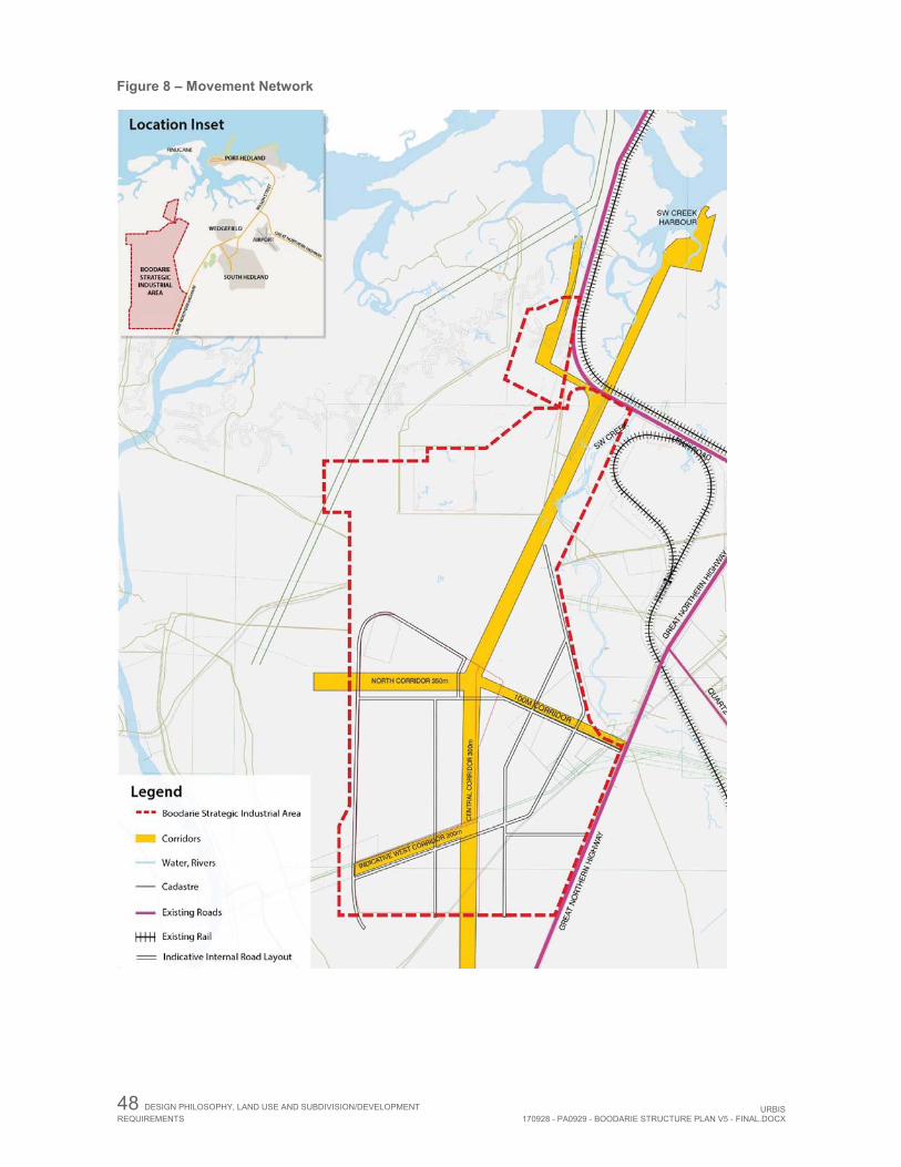
48 DESIGN PHILOSOPHY, LAND USE AND SUBDIVISION/DEVELOPMENT REQUIREMENTS URBIS
170928 - PA0929 - BOODARIE STRUCTURE PLAN V5 - FINAL.DOCX
Figure 8 – Movement Network
URBIS 170928 - PA0929 - BOODARIE STRUCTURE PLAN V5 - FINAL.DOCX
DESIGN PHILOSOPHY, LAND USE AND SUBDIVISION/DEVELOPMENT
REQUIREMENTS 49
4.10.4. Great Northern Highway The current road capacity of the GNH single carriageway is 12,000vpd. The increase in traffic volumes to 2031 without the BSIA development is estimated at 5,720vpd and is therefore well within the current road capacity. With the addition of BSIA development, it is estimated additional traffic of 1500 to 6170vpd would occur, increasing the daily volume from 7,220 to 11,890vpd. This will be at the upper level of capacity for a single carriageway. In view of the increased activity associated with the BSIA, it is considered that the speed limit on GNH should be reduced adjacent to the site from 110km/h to 90km/h. 4.10.5. GNH Intersection Analysis The analysis of the three main access intersections with GNH, namely, North, Central and South considered the following:
Minor modification to the existing intersection to allow two egress lanes in the main access road have been assumed; and
A speed limit of 110km/h is maintained on GNH. Figures within the GHD report recommended intersection layouts for the ultimate development for the three main access roads. The traffic analysis has concluded that a right and left turn lane in GNH are required together with a two lane approach in each of the main access roads and the left turn under stop sign control. For the north and central main access, an acceleration lane is recommended for right turning traffic and in view of the heavy vehicle movement, an acceleration lane for the south access is desirable. It is understood that only 25% of development is likely to occur by 2031, whereas the traffic analysis assumes full development by 2031. Therefore, the intersection construction should be staged to effect:
T Intersections with left and right turn lanes in the first stage. As development increases, the intersections will need to be upgraded to include acceleration lanes
for the right turn movement at the northern and central main access points. To support these decisions, the traffic generated by the development should be carefully monitored over time and intersection upgrade introduced when required. 4.10.6. Interim Development Analysis of the traffic has been undertaken assuming the development of initial stages gain access via the existing Boodarie Station Access Road.
The analysis indicates that a single approach lane in the Boodarie Station Access Road is likely to operate satisfactorily for the interim development. It is noted that southbound through traffic speed on GNH is likely to be impacted at peak times. Therefore, localised widening should be considered to reduce the risk of rear end collision caused by traffic being unable to pass right turning traffic.
50 DESIGN PHILOSOPHY, LAND USE AND SUBDIVISION/DEVELOPMENT REQUIREMENTS URBIS
170928 - PA0929 - BOODARIE STRUCTURE PLAN V5 - FINAL.DOCX
4.10.7. Austroads Intersection Treatment An annual traffic growth rate of 6% over 5 years on GNH represents 338vph resulting in approximately 16 right turning movements into the BSIA. The current right turn into Boodarie Station Access Road during the am peak hour is likely to be around 16 turning movements. These movements are approaching the threshold of Austroads standards, confirming the need for intersection upgrade as traffic volumes increase on the GNH and from within the site.
4.10.8. Off and On Road Parking The car parking demand for each land use should be justified by proponents as part of future development applications. It is considered that car parking restrictions should be imposed to prohibit parking on verges to avoid conflicting movements.
4.10.9. High Wide Loads (HWL) Adequate access should be provided for High Wide Load activity within the BSIA. A preferred route through the BSIA from Great Northern Highway is via the central main access road. It is recommended a secondary route via the South main access road be provided to improve accessibility and circulation for oversize loads. High Wide Load access would connect to the Central Corridor road system and would likely form part of the PAM corridor access.
4.11. UTILITIES 4.11.1. Infrastructure Capacity Provision of infrastructure to developments is to be proponent driven. Whilst industry proponents will be required to generate their own enabling infrastructure such as power and water, constructing and servicing infrastructure for their own needs, the benefits associated with shared services are acknowledged.
LandCorp and JTSI will require a proponents servicing strategy to investigate the opportunity for these to be constructed as shared services to benefit the whole of the BSIA. In this regard, initial investigations have been undertaken in relation to the sharing of some infrastructure items as discussed in further detail within this section of the report.
The existing infrastructure capacity in terms of communications, power, water supply, and gas supply are outlined below and depicted in Figure 10.
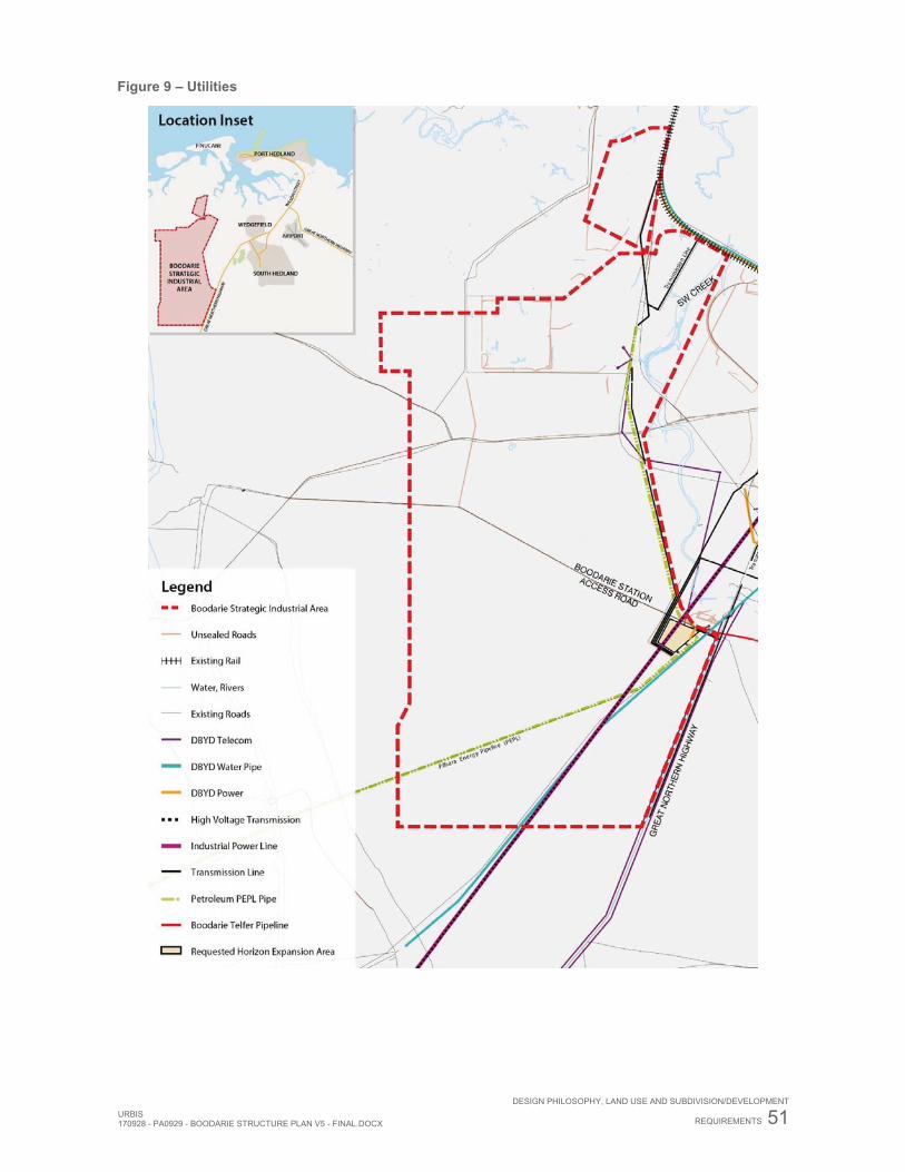
URBIS 170928 - PA0929 - BOODARIE STRUCTURE PLAN V5 - FINAL.DOCX
DESIGN PHILOSOPHY, LAND USE AND SUBDIVISION/DEVELOPMENT
REQUIREMENTS 51
Figure 9 – Utilities
52 DESIGN PHILOSOPHY, LAND USE AND SUBDIVISION/DEVELOPMENT REQUIREMENTS URBIS
170928 - PA0929 - BOODARIE STRUCTURE PLAN V5 - FINAL.DOCX
4.11.2. Communications There is an optic fibre cable installed to the former HBI plant and Alinta Energy Power Station. Telstra will require a site for an exchange and possibly further sites for mobile phone towers.
Reticulation through the BSIA will be undertaken through standard pit and pipe networks, possibly to NBN standards, with the long development time frames expected.
4.11.3. Power Power reticulation and main distribution will originate from the Alinta Energy and Horizon Power station and switchyard/HV infrastructure located at Boodarie and Wedgefield Sub Station, possibly with augmentation from the Hedland Terminal.
Depending upon timing of demand, distribution is expected to consist of a network of HV feeders and substations, with reticulation networks supplying individual industries or clusters of lots. Once more load distribution data is available from potential industries, then fine tuning of the locations closer to the centre of gravity of the demand can be undertaken, as well as the spread of the 33 kV / 415 V substations locations.
To supply the initial stages of development, Horizon Power have indicated that a new 33MVA 66/22kV transformer and switchboard would be required to support the load connection at the Wedgefield Sub Station. A new 22kV feeder of approximately 7kms is required to supply the requested load.
A gas-fired power station with a permanent generation capacity of approximately 200MW is planned for Lot 601. Construction will commence in 2014 and the plant is proposed to be fully commissioned by mid-2016. Power from the plant will be available to support mine and Port infrastructure in the Pilbara, as well as Horizon Power’s residential load.
4.11.4. Water Supply Untreated water is currently supplied to the Alinta Energy Power Station from the Water Corporation’s Yule Borefield pressure main which traverses the BSIA to the Corporation’s South Hedland tank site, with BHPB being directly supplied from that tank site.
The quantity of low and high quality feedwater required for the industrial proponents is high and is to be provided from a combination of sources including existing and new borefields and aquifers, desalination, effluent re-use from wastewater, and possible surface water sources.
Existing WaterCorp infrastructure is at or near capacity, with additional supply expected to come from upgraded or new borefields and desalination. Other sources could include the de-activated Turner River Aquifer and surface water harnessing.
Low quality untreated water supply could also include sources from groundwater and desalination, as well as effluent re-use and surface water harvesting. The Water Corporation is currently investigating a non-potable scheme to supply industry in Port Hedland, and will look at all options for supply and demand from potential industry proponents.
If required by proponents, high quality/potable water for future development of Boodarie, particularly for the initial development, may be supplied by either direct feed from the Water Corporation’s South Hedland Tank Site or from a new tank storage facility potentially located on the higher ground to the south west of the BSIA, up from the nearby Turner River. The new storage facility would be supplied from the South Hedland Tank Site, or other alternative high quality water sources as and when established.
A possible interim option in lieu of new tanks is to utilise existing de-commissioned tanks owned by the Corporation at their Turner River borefield and landholdings; however, this would be subject to further planning and asset condition assessment.
To enable the first stage of development, the Water Corporation has recently agreed in principle to servicing the first 10 lots of development with potable water from the South Hedland scheme.
For the Strategic Industry Area, water could be direct fed from the Corporation’s South Hedland facility. Once many industries require supply, however, it may be more efficient to have a centrally located supply storage facility.
Consideration in the structure plan has also been given to the establishment of a centrally located industry feedwater facility within the BSIA to harvest, recycle and produce water from various potential water sources for industrial use.
URBIS 170928 - PA0929 - BOODARIE STRUCTURE PLAN V5 - FINAL.DOCX
DESIGN PHILOSOPHY, LAND USE AND SUBDIVISION/DEVELOPMENT
REQUIREMENTS 53
During consultation for the structure plan, the WaterCorp advised that it is the license holder for water supply and wastewater in Port Hedland and South Hedland. The BSIA is partly within the current Water Services Licence Area issued by the Economic Regulation Authority (ERA). The central and south-western portions of the BSIA are not covered by the licence area, and should Stage 1 be in this area the proponents would need to submit a formal request to WaterCorp to become the licensed water service provider, and apply to the Economic Regulation Authority (ERA) to extend the licence area.
The preferred proposal would be for water supply via a 150mm to 200mm reticulation size main from the vicinity of the Elevated Tank at South Hedland. A less preferable alternative would be an off-take from the bore water main, with either an elevated tank or booster pump near the first stages of development.
An agreement in principle would be required from LandCorp, the Town of Port Hedland and Pilbara Cities prior to finalisation of a subdivision agreement. All proposals will be fully funded by the proponent.
4.11.5. Gas Supply Gas is currently supplied to the site via the APA Group pipeline, which supplies gas to BHPB, the Alinta Energy Power Stations (through agreement with BHPB) and through to Telfer. Current mains are already at contracted capacity, and will either require further upgrading or new mains to supply any new demand. Proponents are required to liaise with APA to determine individual gas requirements and servicing if required.
4.11.6. Priority Basic Raw Materials and Key Extraction Areas Sand extraction for the construction industry from a sand ridge along the western margin of the site is currently the only significant raw material extraction. BJ Young undertakes this under an allocated mining lease M45/681, expiring 9 June 2017. The company is pursuing an extension of the lease further along the sand ridge.
Whilst it is recognised that sand is an important material for the development of the region, future extraction operations should not impact the development of the BSIA. In particular, future sand extraction projects must consider the potential of flooding as a result of mining the sand ridge along the western boundary of the BSIA. The height of the sand ridge should be maintained at appropriate levels to mitigate against the potential flooding from the Turner River.
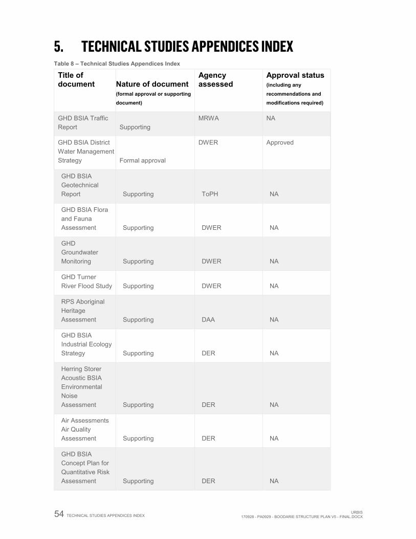
54 TECHNICAL STUDIES APPENDICES INDEX URBIS170928 - PA0929 - BOODARIE STRUCTURE PLAN V5 - FINAL.DOCX
5. TECHNICAL STUDIES APPENDICES INDEX Table 8 – Technical Studies Appendices Index
Title of document Nature of document
(formal approval or supporting document)
Agency assessed
Approval status (including any
recommendations and modifications required)
GHD BSIA Traffic Report Supporting
MRWA NA
GHD BSIA District Water Management Strategy Formal approval
DWER Approved
GHD BSIA Geotechnical Report Supporting ToPH NA
GHD BSIA Flora and Fauna Assessment Supporting DWER NA
GHD Groundwater Monitoring Supporting DWER NA
GHD Turner River Flood Study Supporting DWER NA
RPS Aboriginal Heritage Assessment Supporting DAA NA
GHD BSIA Industrial Ecology Strategy Supporting DER NA
Herring Storer Acoustic BSIA Environmental Noise Assessment Supporting DER NA
Air Assessments Air Quality Assessment Supporting DER NA
GHD BSIA Concept Plan for Quantitative Risk Assessment Supporting DER NA
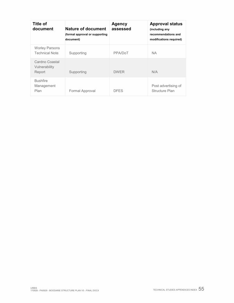
URBIS 170928 - PA0929 - BOODARIE STRUCTURE PLAN V5 - FINAL.DOCX
TECHNICAL STUDIES APPENDICES INDEX 55
Title of document Nature of document
(formal approval or supporting document)
Agency assessed
Approval status (including any
recommendations and modifications required)
Worley Parsons Technical Note Supporting PPA/DoT NA
Cardno Coastal Vulnerability Report Supporting DWER N/A
Bushfire Management Plan Formal Approval DFES
Post advertising of Structure Plan
URBIS 170928 - PA0929 - BOODARIE STRUCTURE PLAN V5 - FINAL.DOCX
APPENDICES
DISCLAIMER This report is dated 7 October 2016 and incorporates information and events up to that date only and excludes any information arising, or event occurring, after that date which may affect the validity of Error! Reference source not found.’s (Urbis) opinion in this report. Urbis prepared this report on the instructions, and for the benefit only, of LandCorp (Instructing Party) for the purpose of the Boodarie Strategic Industrial Area Structure Plan (Purpose) and not for any other purpose or use. To the extent permitted by applicable law, Urbis expressly disclaims all liability, whether direct or indirect, to the Instructing Party which relies or purports to rely on this report for any purpose other than the Purpose, and to any other person which relies or purports to rely on this report for any purpose whatsoever (including the Purpose).
In preparing this report, Urbis was required to make judgements which may be affected by unforeseen future events, the likelihood and effects of which are not capable of precise assessment.
All surveys, forecasts, projections and recommendations contained in or associated with this report are made in good faith and on the basis of information supplied to Urbis at the date of this report, and upon which Urbis relied. Achievement of the projections and budgets set out in this report will depend, among other things, on the actions of others over which Urbis has no control.
In preparing this report, Urbis may rely on or refer to documents in a language other than English, which Urbis may arrange to be translated. Urbis is not responsible for the accuracy or completeness of such translations and disclaims any liability for any statement or opinion made in this report being inaccurate or incomplete arising from such translations.
Whilst Urbis has made all reasonable inquiries it believes necessary in preparing this report, it is not responsible for determining the completeness or accuracy of information provided to it. Urbis (including its officers and personnel) is not liable for any errors or omissions, including in information provided by the Instructing Party or another person or upon which Urbis relies, provided that such errors or omissions are not made by Urbis recklessly or in bad faith.
This report has been prepared with due care and diligence by Urbis and the statements and opinions given by Urbis in this report are given in good faith and in the reasonable belief that they are correct and not misleading, subject to the limitations above.