spin tracking in rhic with one full snake and one partial ... · spin tracking in rhic with one...
TRANSCRIPT

C-A/AP/#100 June 2003
Spin Tracking in RHIC with one Full Snake and one Partial Snake. Effect of Orbit Harmonics
A. U. Luccio
Collider-Accelerator Department Brookhaven National Laboratory
Upton, NY 11973

Spin Tracking in RHIC with one Full Snake and one
Partial Snake. Effect of Orbit Harmonics
A.U. Luccio
June 25, 2003
1 Introduction
Both rings in RHIC, Blue and Yellow are furnished with two helical full snakes to allowthe acceleration of polarized protons to the highest energy of the machine with minimalpolarization loss. During the polarized proton run in the Spring of 2003 the coils of thecentral sections of one of the two snakes of the Yellow Ring were damaged, so the snakecould not be operated as a full snake. However, by adjusting the currents in the outer snakecoils, this snake could still be used as a partial snake. The polarization of the beam couldstill be preserved, altough to a lesser degree. This report describes tracking of the spin withthe code Spink in RHIC-Yellow, with one full snake and one partial snake, to show whatare the value of the beam polarization that can be obtained in these conditions.
2 Spin rotation in the snakes
The snakes in RHIC are made up of four helical dipoles. If all helices are working properly,the snake is rotating the spin by µ = 1800, from the vertical up to down (or vice-versa)around an axis laying in the horizontal plane and making an angle of ±450 with the longi-tudinal azis z. The angle µ is independent of the energy of the protons. This situation isshown in Fig. 1. Field, orbit and spin components in a partial snake, with no inner helices,are shown in Fig. 2. This snake is set to produce a spin rotation of µ = 1580 around an axisat −450. The orbit has a vertical excursion that depends on energy: maximum at the lowestenergy in RHIC (the figure shows a vertical bump of about 5cm at γ = 26 -injection energy).To respect the clearance of the snake, a vertical bump should be put in RHIC-Yellow toupset half of this excursion. The created bump should be of ∼ 4cm at injection and shoulddecay completely for γ = 50.
3 MAD work
Spink reads the accelerator configuration from MAD. In the present case we wanted toconfigure MAD to take into consideration the machine imperfections -foremost the measuredvertical displacement of the machine magnets- and to correct the orbit in MAD with theMicado algorithm to produce an orbit as horizontal possible. At variance with more commonconditions, where the orbit is corrected to make it centered in the machine multipoles, this isthe best condition to preserve polarization: spin orientation is best preserved when carriedby particles moving in an horizontal plane. In MAD, the commands to achieve this condionsare listed in Table 1.
After the output of MAD is obtained, we run the Spink pre-processor mad-read to preparethe input to Spink in the form of a file -call it “xxx.sy” - containing the transfer maps fromMAD, the Twiss functions, the errors, the COD orbit and finally the one-turn orbit map,made symplectic. An example of entry in that file is given in Table A.
1

0 4 8 12−1
−0.5
0
0.5
1 −0.005
0
0.005
0.01−4
−2
0
2
4
AUL 030416−001
Bx
By
X
Y
Sx
Sy
γ=100
Figure 1: Full snake. From top to bottom: Field, orbit, spin. Proton energy γ = 100. Spinand field along the trajectory.
0 4 8 12−1
−0.5
0
0.5
1 −0.06
−0.04
−0.02
0.00
0.02−6
−4
−2
0
2
4
6
AUL 030416−004
Gγ∴4=46.6 γ=26 B=4TBx
By
Bz
X
Y
Sx
Sy
Sz
Figure 2: partial snake. Field, orbit, spin. Proton energy γ = 26
2

� ��� ����� ��� �� � �� ���� ������������������ � ���� ! �"#��$% � ����$ �& � �
'() *(+ ,
-� ./� ��� �
� � �� � - � �� " �
� � �0 12
3 � �� 456 78 �� �� �� �
�" 9 :
;
�
;<=>
(?(@(A B,
�� � �3 � �
�� � ����
�� � �C � �#� "
�� � �� � �D�$
%
E F
G� H.I <
J K�3
F �=E =E FL >>>>>>� M>>
� � �" � �D� �
! ;0ON��"2
! F0 ��� ���� �2
����
$ � �
! � :!
/� � �! � :!
%
; �F;<>HH>>9>>>�QP>F
> �>>>>>>>>>>>>� M>>> �>>>>>>>>>>>>� M>>> �>>>>>>>>>>>>� M>>> �>>>>>>>>>>>>� M>>> �>>>>>>>>>>>>� M>>
� � � �
R S
R T
R U
RV0 �� � � ��" 2
RW0 � � ��" �2
RX0 � � ��" �2
.K� �"
.! ;
.! F
.! Y
%
> �>>>>>>>>>>>>� M>>9 �;>>>>>>>>>>>� P>E
> �>>>>>>>>>>>>� M>>> �>>>>>>>>>>>>� M>>> �>>>>>>>>>>>>� M>>> �>>>>>>>>>>>>� M>>
%
> �>>>>>>>>>>>>� M>>> �>>>>>>>>>>>>� M>>> �>>>>>>>>>>>>� M>>> �>>>>>>>>>>>>� M>>
Z� .�/� �D� �
S\[
] S [
T [
] T [
%
PE �;L;==E ;YE H>>� P>L; �F<YH9;<Y<H>>� P>LPH�;;H
L <;YH9H>>� P>H
; �;99H9H9;<>>>� P>H
� #��� �
^�_
` _
^�a
` a
%
; �HH=9=LLLL>>>� M>>; �H9;<FLL Y=>>>� M>;PF�;E 9
;ELE YY>>>� M>>E �HY>FH9YF<>>>� M>;
Z� .��� �" �
S�bcd
] S bcd
T bcd
] T bcd
�:�� " � ��� �
%
PF�Y
>L =F9>;F>>>� P>L; �F<Y<9;HEL>>>� P>LPY�Y<
F=YL 9F=>>>� P>H
; �;99H9H9;L>>>� P>H
; �>=<ELE YFH>>>� M>F
� � �� �
- �� ��
%
=�==
=F<><>>>>>�QP>;F �=E =YHE F>9YL =� M>>P;�>F=
E =<=9=9;<� P>L; �;EE H=<LE>LE <� P>H
> �>>>>>>>>>>>>� M>>; �L =YYFY;;E ;<H�QP>F
%
PH�>;Y
<=L Y>>>>>� P>H=�==
=F<><F9E >9� P>;F �>FYYYE 9<9;<F�QP;>P;�>YF
E HHE >;H;L� P>L
> �>>>>>>>>>>>>� M>>; �F;<>YYH>;L FH�QP>F
%
; �>YFE HHE >>>>>�QP>L; �F>HH>>=>YE FH� P>H
; �>>>>>>>>>>>>� M>>F �=E =E F<=>>>>>� M>>> �>>>>>>>>>>>>� M>>PF�H
>E;E><==YL =�QP>H
%
; �=L ;H<=E >>>>>�QP;>; �>YHY99E >F=E F� P>L=�>H9
H>FF9L 9F=�QP;L
; �>>>>>>>>>>>>� M>>> �>>>>>>>>>>>>� M>>P
E �L 9;99=;<<E 9Y�QP>9
%
P;�F
;<>YYH>>>>>� P>FP;�L =
YYFY>>H>=H�QP>F
E �=>LEE FF=9L H<�QP>9
PF�H
>E;E><==F9>� P>H
; �>>>>>>>>>>>>� M>>PY�;<9=
HYE HL YHE�QP>H
%
> �>>>>>>>>>>>>� M>>> �>>>>>>>>>>>>� M>>> �>>>>>>>>>>>>� M>>> �>>>>>>>>>>>>� M>>> �>>>>>>>>>>>>� M>>; �>>>>>>>>>>>>� M>>
eff B(+ ,
g _
g a
h i
��D� ��D�$
%
F �9FF>>FYE H>>>� M>;F �=FF==L 9Y=>>>� M>;F �F=<9E Y<FF>>>� M>;Y �9FLE =>H=>>>>� M>Y
����P� � ��� ��
%
9 �L >E >F9;L =<><�QP>;9 �=YE =<F>L F99=� M>>P
E �==FE Y>;HEL;F� P>Y
; �>E Y<E FF;F>FE� P>;
> �>>>>>>>>>>>>� M>>E �9=;E =Y9Y=>EE�QP>F
%
P;�<
>;HE 9F9<HF=� P>;P
E �=HHE <>L 9;=LE�QP>;PY�>Y9
9FHE =FY>F� P>Y
P<�>H<
9H<E Y<9>;� P>Y
> �>>>>>>>>>>>>� M>>PF�H
LEE YY<Y=Y>9�QP>Y
%
PY�Y9
Y<H<9H;9L ;� P>FPF�=
FY<L <>FH;>H�QP>;P;�YY
L >;;E H<Y=Y� P>F=�9<
E ;9><E >F;<� M>>> �>>>>>>>>>>>>� M>>P;�E <<
;Y=>YY>L 9�QP>F
%
F �H<<L >;<;>YH>�QP>EP9�>E 9
L ;=H>Y<9Y�QP>YP;�>;<=
9<F;>;L <� P>;F �<YYEE =;Y9;>F� P>;
> �>>>>>>>>>>>>� M>>; �;=E HL F;;L 9E F�QP>Y
%
PH�HH
<H;FF>FF9Y� P>YP
L �<=9L =YHY9Y>>�QP>E; �YE HH;9;>Y>EE�QP>Y
P;�H<
L F><=L F99>� P>F
; �>>>>>>>>>>>>� M>>P
L �F>;=YYF9E <E H� M>>
%
> �>>>>>>>>>>>>� M>>> �>>>>>>>>>>>>� M>>> �>>>>>>>>>>>>� M>>> �>>>>>>>>>>>>� M>>> �>>>>>>>>>>>>� M>>; �>>>>>>>>>>>>� M>>
� ��� ��� ��
%
F �;===FYL H9Y9>�QP>;F �Y>>HHELLE F<<� P>;
3

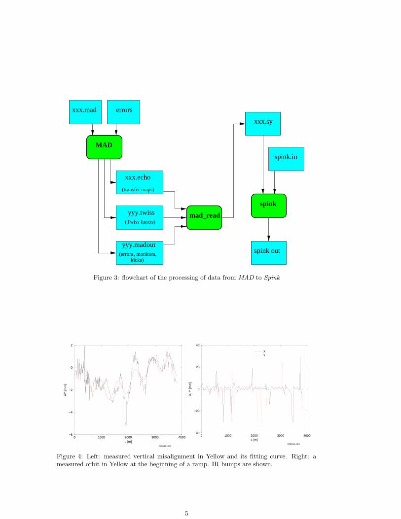
Table 1: MAD8 commands as in file xxx.mad, see diagram of Fig. 3
command resultYMON := 0 set reference level for BPMsUSE, RHIC (“RHIC” set to “Yellow”)CALL, filename = ’align-mad.dat’ file containing alignment errorsSETOPTS, echo set up echo fileCORRECT, error = 3.e-4, iterate = 10 invoke Micado, c2list, m1list ,m2list print list of correctors and monitorsSELECT, flag=FIRST, range =full write first order transfer maps to echo filePRINT, RHIC set up output file .madoutTWISS, tape=’yellow.twiss’ calculate twiss values and print optics to a fileSELECT, error ,range=full use errorsEPRINT,range=full print imperfection table to madout
The complete cycle of codes/pre-processors for this process is diagrammatically shownin Fig. 3.
4 Spin Tracking in Yellow with Alignment Errors
Fig. 4 shows the measured vertical alignment errors in Yellow and their FFT. A 1.st and6.th harmonic are apparent. The curve is best fit with the following function
y = a0 + a1 sin
(
62π
Ls + a2
)
+ a3 sin
(
2π
Ls + a4
)
,
with L = 3827.49 the length of the machine, and
a0 = −0.8604, a1 = −0.7728, a2 = 1.4339, a3 = −1.2411, a4 = 5.6503
The figure also shows a typical measured closed orbit. This orbit is measured at the begin-ning of the ramp, however it did not change appreciably later in the ramp. The orbit showssome very marked peaks in correspondence to the Intersection Regions, where bumps whereapplied. Artificially cleaning the IR bumps, the orbits appears as in Fig. 5, together withits harmonic analysis. The figure shows a sizable content of harmonics 1, 2, 6, 12 and 18.
Spink tracks polarized protons through RHIC. We are showing the results of one particletracking during the acceleration ramp, from injection at γ = 26 to γ = 107 with the machineset for β∗ = 10m in all IR’s. The particle was selected on the contour of phase space ellipsewith emittances 20 and 15 mm-mrad in x and y, respectively. Vertical displacement errorsin the elements of the machine are included, as well as an orbit bump that offsets thevertical orbit in the partial snake, according to the specification described in Sec. 2. Thebump is maximum at injection and decays linearly to zero in 50,000 turns, i.e. when theenergy increases from injection to γ = 34.9(Gγ = 62.637). Fig. 6 shows the behaviour ofthe vertical component of the spin when using two full snakes, or a full snake and a partialsnake. The orbit is corrected with Micado to y = 0. For both tracking the spin was put inthe matched position at the beginning, i.e. the orientation coincident with the stable spindirection at that point in the lattice, found by stroboscopic averaging in Spink. The stablespin axis for the second case has coordinates (Sx, Sy, Sz) = (0.106427, 0.989719,−0.095544).
5 Orbit Harmonics
Some of the polarization losses observed during the experiment may have been caused byimperfection resonances that can be simulated by introducing harmonics in the distorted
4
spink.in
spink
spink out
xxx.sy
mad_read
(errors , monitors,kicks)
yyy.madout
(Twiss functs)
yyy.twiss
(transfer maps)
MAD
xxx.echo
xxx.mad errors
Figure 3: flowchart of the processing of data from MAD to Spink
0 1000 2000 3000 4000L [m]
−6
−4
−2
0
2
δY [m
m]
030618−004
0 1000 2000 3000 4000L [m]
−40
−20
0
20
40
X, Y
[mm
]
XY
030618−001
Figure 4: Left: measured vertical misalignment in Yellow and its fitting curve. Right: ameasured orbit in Yellow at the beginning of a ramp. IR bumps are shown.
5

0 1000 2000 3000 4000L [m]
−0.01
−0.005
0
0.005
0.01
X, Y
[mm
]
030618−002
0 2 4 6 8 10 12 14 16 18 20harmonic #
030618−003
Figure 5: Left: measured orbit in Yellow at the beginning of a ramp. IR bumps removed.Right: FFT of the vertical orbit. Harmonics 1, 2, 6, 12 and 18 are evident.
40 60 80 100 120 140 160 180 200Gγ
0.85
0.9
0.95
1
0.95
0.96
0.97
0.98
0.99
1
030619−004
Figure 6: Top: tracking with errors corrected by Micado to y = 0 plus orbit bump. Use 2full snakes. Lower: Use a full snake + a partial snake + plus orbit bump..
6
-0.006
-0.004
-0.002
0
0.002
0.004
0.006
0 500 1000 1500 2000 2500 3000 3500 4000
030609-002
’COD.dat’ u 1:2’COD.dat’ u 1:3
’test.xOrbAtMON’ u 1:2’test.yOrbAtMON’ u 1:3
0.001
0.01
0.1
1
10
2 4 6 8 10 12
030609-003
’test-FFt.dat’ u 1:3’test-FFt.dat’ u 1:4
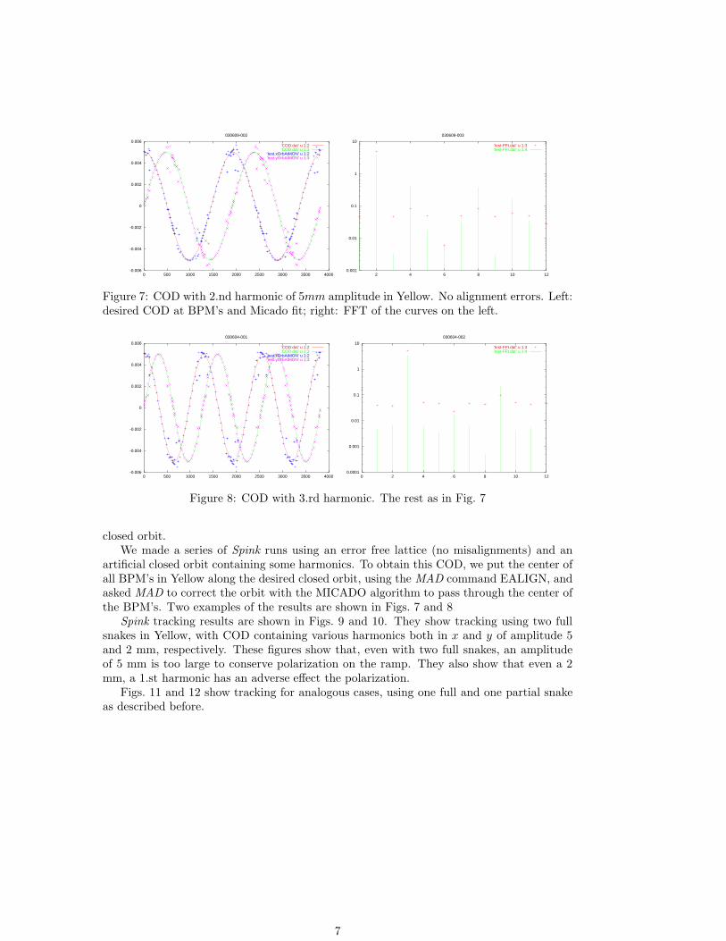
Figure 7: COD with 2.nd harmonic of 5mm amplitude in Yellow. No alignment errors. Left:desired COD at BPM’s and Micado fit; right: FFT of the curves on the left.
-0.006
-0.004
-0.002
0
0.002
0.004
0.006
0 500 1000 1500 2000 2500 3000 3500 4000
030604-001
’COD.dat’ u 1:2’COD.dat’ u 1:3
’test.xOrbAtMON’ u 1:2’test.yOrbAtMON’ u 1:3
0.0001
0.001
0.01
0.1
1
10
0 2 4 6 8 10 12
030604-002
’test-FFt.dat’ u 1:3’test-FFt.dat’ u 1:4
Figure 8: COD with 3.rd harmonic. The rest as in Fig. 7
closed orbit.We made a series of Spink runs using an error free lattice (no misalignments) and an
artificial closed orbit containing some harmonics. To obtain this COD, we put the center ofall BPM’s in Yellow along the desired closed orbit, using the MAD command EALIGN, andasked MAD to correct the orbit with the MICADO algorithm to pass through the center ofthe BPM’s. Two examples of the results are shown in Figs. 7 and 8
Spink tracking results are shown in Figs. 9 and 10. They show tracking using two fullsnakes in Yellow, with COD containing various harmonics both in x and y of amplitude 5and 2 mm, respectively. These figures show that, even with two full snakes, an amplitudeof 5 mm is too large to conserve polarization on the ramp. They also show that even a 2mm, a 1.st harmonic has an adverse effect the polarization.
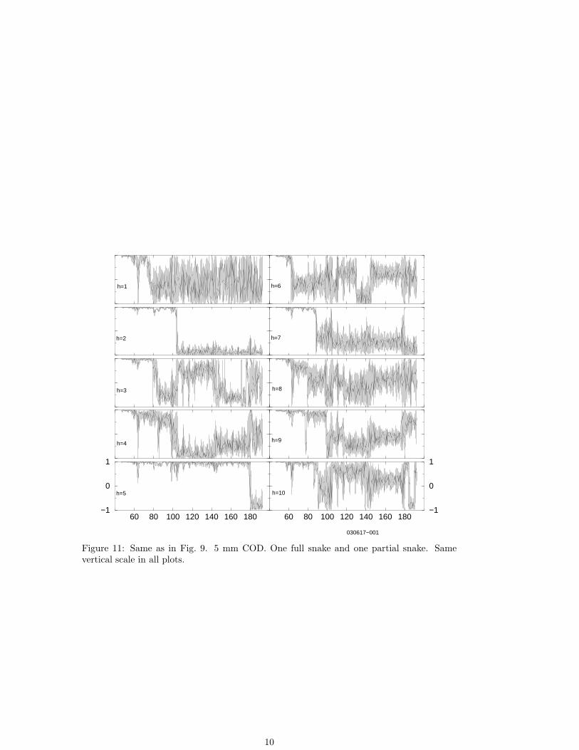
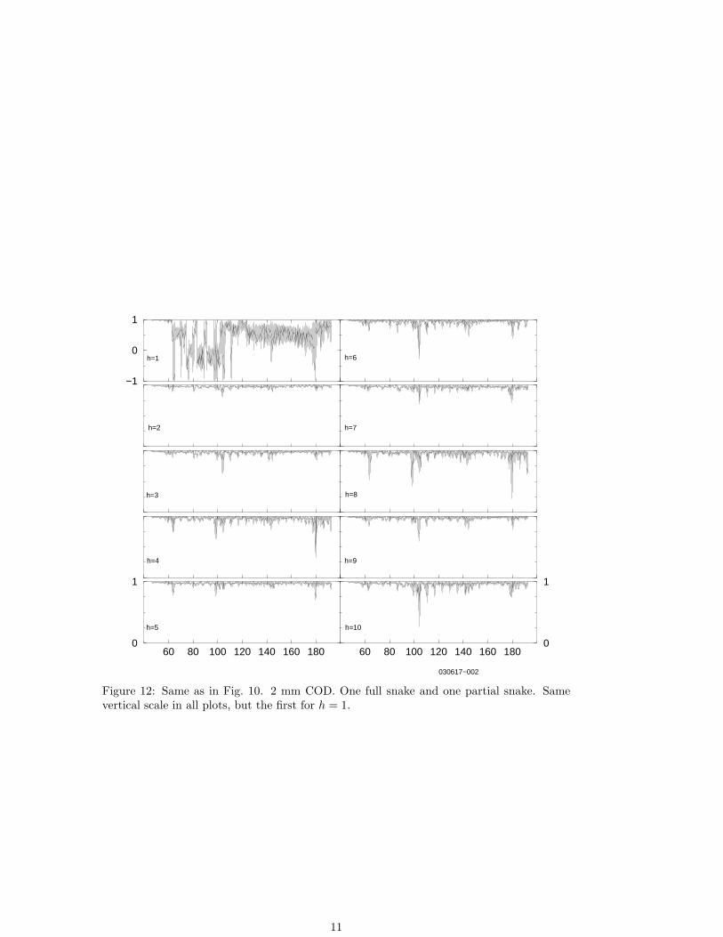
Figs. 11 and 12 show tracking for analogous cases, using one full and one partial snakeas described before.
7

60 80 100 120 140 160 180−1
0
1
60 80 100 120 140 160 180−1
0
1
030617−003
h=1
h=2
h=3
h=4
h=5
h=6
h=7
h=8
h=9
h=10
Figure 9: Track in a COD with several harmonic content of 5mm amplitude in Yellow. Twofull snakes.No alignment errors. Vertical component of spin vs. G|gamma. The verticalscale is the same in all plots. The curves show polarization loss and spin flips in variousenergy regions.
8

60 80 100 120 140 160 1800
1
−1
0
1
60 80 100 120 140 160 1800
1
030617−004
h=1
h=2
h=3
h=4
h=5
h=6
h=7
h=8
h=9
h=10
Figure 10: Same as in Fig. 9 with full snakes. 2mm COD amplitude. The vertical scale isthe same in all plots, but the first for h = 1.
9
60 80 100 120 140 160 180−1
0
1
60 80 100 120 140 160 180−1
0
1
030617−001
h=1
h=2
h=3
h=4
h=5
h=6
h=7
h=8
h=9
h=10
Figure 11: Same as in Fig. 9. 5 mm COD. One full snake and one partial snake. Samevertical scale in all plots.
10
60 80 100 120 140 160 1800
1
−1
0
1
60 80 100 120 140 160 1800
1
030617−002
h=1
h=2
h=3
h=4
h=5
h=6
h=7
h=8
h=9
h=10
Figure 12: Same as in Fig. 10. 2 mm COD. One full snake and one partial snake. Samevertical scale in all plots, but the first for h = 1.
11