spherically imploding plasma liners as a standoff driver
TRANSCRIPT

IEEE TRANSACTIONS ON PLASMA SCIENCE, VOL. 40, NO. 5, MAY 2012 1287
Spherically Imploding Plasma Liners as a StandoffDriver for Magnetoinertial Fusion
S. C. Hsu, T. J. Awe, S. Brockington, A. Case, J. T. Cassibry, G. Kagan, S. J. Messer,M. Stanic, X. Tang, D. R. Welch, and F. D. Witherspoon
(Invited Paper)
Abstract—Spherically imploding plasma liners formed by merg-ing an array of high Mach number plasma jets are a proposedstandoff driver for magnetoinertial fusion (MIF). This paper givesan updated concept-level overview of plasma liner MIF, includingadvanced notions such as standoff methods for forming and mag-netizing the fuel target and liner shaping to optimize dwell time.Results from related 1-D radiation-hydrodynamic simulations oftargetless plasma liner implosions are summarized along with newanalysis on the efficiency of conversion of the initial liner kineticenergy to stagnation thermal energy. The plasma liner experiment(PLX), a multi-institutional collaboration led by the Los AlamosNational Laboratory, plans to explore the feasibility of formingspherically imploding plasma liners via 30 merging plasma jets.In the near term, with modest pulsed power stored energy of�1.5 MJ, PLX is focusing on the generation of centimeter-,microsecond-, and megabar-scale plasmas for the fundamentalstudy of high energy density laboratory plasmas. In the longerterm, PLX can enable a research and development path to plasmaliner MIF ultimately requiring compressing magnetized fusionfuel to �100 Mbar.
Index Terms—Fusion reactors, plasmas.
I. INTRODUCTION
THIS paper describes the concept of spherically implodingplasma liners as a standoff driver for magnetoinertial
fusion (MIF) [1], [2] as well as a nascent research program [3]that can ultimately assess and demonstrate the concept’s feasi-
Manuscript received September 13, 2011; revised December 5, 2011;accepted January 28, 2012. Date of publication March 12, 2012; date ofcurrent version May 9, 2012. This work was supported in part by the Officeof Fusion Energy Sciences of the U.S. Department of Energy under ContractDE-AC52-06NA25396, Contract DE-FG02-05ER54810, Contract DE-FG02-05ER54835, and Contract DE-SC0003560, and in part by the Los AlamosNational Laboratory Directed Research and Development (LDRD) Program.
S. C. Hsu is with the Physics Division, Los Alamos National Laboratory, LosAlamos, NM 87545 USA (e-mail: [email protected]).
T. J. Awe was with the Physics Division, Los Alamos National Laboratory,Los Alamos, NM 87545 USA. He is currently with Sandia National Laborato-ries, Albuquerque, NM 87185 USA.
S. Brockington, A. Case, S. J. Messer, and F. D. Witherspoon are withHyperV Technologies Corporation, Chantilly, VA 20151 USA.
J. T. Cassibry and M. Stanic are with the Propulsion Research Center,University of Alabama in Huntsville, Huntsville, AL 35899 USA.
G. Kagan and X. Tang are with the Theoretical Division, Los AlamosNational Laboratory, Los Alamos, NM 87545 USA.
D. R. Welch is with Voss Scientific, Albuquerque, NM 87108 USA.Color versions of one or more of the figures in this paper are available online
at http://ieeexplore.ieee.org.Digital Object Identifier 10.1109/TPS.2012.2186829
bility. The imploding spherical plasma liners are to be formedby an array of merging plasma jets launched by electromagneticplasma accelerators from the periphery of a large sphericalvacuum chamber. Once formed, the spherical plasma liner im-plodes toward the origin (carrying the initial momentum of theplasma jets). In principle, at least two distinct MIF approachesmight be enabled by this scheme: 1) plasma liner compressionof a preformed magnetized target plasma, similar to magnetizedtarget fusion (MTF) concepts [4]–[7], and 2) the imploding(“composite”) plasma liner itself carries the main fusion fuelat its leading edge, and the fuel is magnetized prior to compres-sion. In either case, the imploding liner may be a compositeliner carrying a dense deuterium–tritium (D-T) “afterburner”layer in front to provide additional fuel that may burn andamplify the total fusion yield if it can be heated to the necessaryconditions by the α particles and radiation from the compressedburning main target fuel. For the first approach described above,it is envisioned that a subset of plasma jets (fired first) wouldcarry the main D-T fuel, which would get magnetized prior tocompression, whereas the remainder of the jets (fired slightlylater) carry the composite liner material consisting of the D-Tafterburner layer in front and a heavier inert species in therear. Much further research is required to develop credibleimplementations of either approach and to determine whichapproach is more favorable for fusion energy.
The spherically imploding plasma liner concept for MIFwas first proposed by Thio et al. [8], [9] in the late 1990s,inspired by Thio’s extensive work in the area of electromagneticplasma accelerators coupled with a desire for an MIF standoffdriver that would avoid repetitive destruction of solid liners andtransmission lines. Analytic calculations [8] and 3-D hydro-dynamic simulations [10] were performed to provide the firstassessments of the plasma jet parameters required to form aplasma liner and compress a magnetized target plasma to fusionconditions. It was realized that electromagnetic plasma acceler-ators at the time could not achieve the required combinationof mass, density, and velocity (described in Section III-A).Consequently, Thio carried out research [11] that led to a the-oretical understanding, supported by numerical modeling [12],of how to improve on existing electromagnetic plasma accel-erators to achieve the required jet parameters. The key insightswere to use a preionized plasma rather than a neutral gas fill inthe accelerator stage and to prevent blowby instability [12] by
0093-3813/$31.00 © 2012 IEEE

1288 IEEE TRANSACTIONS ON PLASMA SCIENCE, VOL. 40, NO. 5, MAY 2012
shaping the accelerator electrodes, which allowed most of theplasma fill mass to get accelerated to high velocity.
In 2004, an experimental research program and HyperVTechnologies Corp. were initiated to build and optimize elec-tromagnetic plasma accelerators based on the new insightsdeveloped over the prior several years. Since then, HyperVhas demonstrated steady advances and set records for thecombination of jet mass, density, and velocity [13]. Their initialwork focused on the larger coaxial guns with shaped electrodes[14], [15], as suggested by Thio’s research. In the past fewyears, HyperV’s focus has shifted (temporarily) to simpler morecompact parallel plate “mini-railguns” that were originallyintended only to ionize and inject the plasma prefill into thecoaxial guns. However, it was realized that the mini-railguns,much simpler and less expensive than the coaxial guns, couldachieve the combination of mass (few milligrams), ion density(1017 cm−3), and velocity (50 km/s) required for subscale (andtargetless) spherical plasma liner formation and the implosionexperiments to be carried out on the plasma liner experiment(PLX) [3] at the Los Alamos National Laboratory (LANL).Thus, for reasons of cost and expediency, mini-railguns arereceiving most of the present research attention, although itmust be emphasized that the coaxial guns (and their furtherdevelopment) are needed for fusion energy relevant plasmaliner implosions due to their projected ability to accelerate largemasses (10–100 mg) to high velocities (�100 km/s), their po-tential for forming composite (layered) jets, and their lower im-purity levels. There is also potential for other fusion energy [16]spin-off applications, such as tokamak refueling or edge local-ized mode pacing, for HyperV’s plasma guns.
In 2008, a workshop [17] was held at LANL to ponderthe next steps for developing the plasma liner MIF concept.Several studies, summarized in [17], suggested that this concepthas promise both for reaching high energy density (HED)conditions and for MIF, but support for the concept was notunanimous among the attendees [18]. The workshop providedan update on the status of plasma gun development, showingthat the gun technology was ready for a subscale plasma linerformation demonstration. In addition, included in the workshopwere several presentations related to a code development effortto combine the electromagnetic particle-in-cell (PIC) capabilityof the Large Scale Plasma (LSP) simulation code [19] withPrism Computational Sciences’ [20] advanced equation-of-state (EOS) and opacity models. Such a modeling capabilityis required to fully assess the plasma liner MIF concept, partic-ularly with respect to modeling plasma jet formation and gunphysics, as well the significant portions of the liner evolutionwhere radiative and kinetic effects are important. Furthermore,such a code capability would benefit the entire field of HEDlaboratory plasma research. A large subset of the workshopattendees believed that much more research was warranted andneeded to fully assess the potential of the concept. A teamwas assembled to formulate the present PLX research programaimed at exploring and demonstrating the feasibility of formingspherically imploding plasma liners via merging plasma jets toreach 1 Mbar of peak pressure upon stagnation. With a rela-tively modest investment, PLX promises near term assessmentof the feasibility and quality of plasma liner formation via
merging plasma jets while establishing a unique experimen-tal facility capable of forming centimeter-, microsecond-, andmegabar-scale plasmas for HED scientific studies. PLX is alsoa logical first step toward a potential plasma liner MIF researchand development program.
Construction of the PLX facility at LANL was completed inAugust 2011, and experimental physics campaigns on single-jet propagation and two-jet merging are now underway [3].Thirty jet experiments to form and study converging plasmaliners (without a magnetized target) expected to reach 1 Mbarof peak pressure are to begin in 2013 (subject to availability offunding). Radiation-hydrodynamic simulations [21] using the1-D Lagrangian RAVEN code [22] have explored both PLX-and MIF-relevant liner parameter spaces (without a magnetizedtarget) and established a physical picture of liner implosion,stagnation, and poststagnation dynamics. Ideal hydrodynamicssimulations using the 3-D Smooth Particle HydrodynamicsCode (SPHC) [24] are being used to evaluate important issuesof 30 jet implosions and peak pressure scaling with initial jetparameters [25]. The LSP code with EOS/opacity modelingcapability is run using a two-fluid model (with collisions be-tween ions and electrons modeled as drag terms in the fluidequations of motion) [26] to generate detailed predictions of jetpropagation. For jet merging predictions, the LSP code is runusing a collisional hybrid PIC model with kinetic ions and fluidelectrons. Synthetic interferometry and spectroscopy data aregenerated from the simulation output, all of which will guideinitial experiments and be compared directly with experimentaldata. Tech-X Corp.’s Nautilus code [27], a Eulerian two-fluidmagnetohydrodynamics (MHD) code with EOS modeling, isalso being used as an independent comparison with the LSPresults. Detailed research results from the SPHC, LSP, andNautilus codes will be reported in separate forthcoming papers.The PLX facility will also be used to study cosmically relevantcollisionless shocks [28] generated by the head-on collision oftwo lower-density but higher-velocity plasma jets. The facilityhas the potential to become a unique experimental platform forscientific studies of many of the research areas recognized inthe report on HED laboratory physics research needs [29].
The rest of this paper is organized as follows. Section II de-scribes the key features of MIF. Section III provides a concept-level description of plasma liner MIF. Section IV summa-rizes recent 1-D radiation-hydrodynamic scaling studies of thePLX- and MIF-relevant parameter space of imploding sphericalplasma liners (without a magnetized target), and Section Vdescribes the PLX facility and research plan. The final sectionprovides a summary.
II. KEY FEATURES OF MIF
MIF [1], [2] is a class of pulsed fusion approaches thatincludes a strong magnetic field in the compressed fusion fuel.The key resultant physics effects of the magnetic field are that itreduces thermal conduction within and enhances fusion chargedproduct heating of the compressed burning fuel. The primarybenefits are a significant enlargement of the areal density (ρr)parameter space for ignition [2] and relaxed requirements onimplosion velocity. Batch burn (as opposed to propagating

HSU et al.: SPHERICALLY IMPLODING PLASMA LINERS AS A STANDOFF DRIVER FOR MIF 1289
burn) ignition becomes possible at ρr � 0.01 g/cm2, and Brrather than ρr becomes the key figure of merit for fusion igni-tion [30]. In the ρr ∼ 0.01 g/cm2 ignition regime, MIF exploitslower required implosion velocities (1–100 km/s), allowing theuse of more economic efficient pulsed power drivers (comparedto laser drivers) with up to 50% “wall-plug” efficiency [31],[32]. With such efficiencies, MIF energy gains as low as 20could give a gain efficiency product of 10, which is the nominalrequirement for a viable inertial fusion energy (IFE) concept.It is important to note that, unlike in pure inertial confinementfusion (ICF), where the inertial confinement is determined bythe fuel ρr � 1 g/cm2, in MIF, the inertial confinement isprovided by the liner ρr, which is much higher than the fuelρr ∼ 0.01 g/cm2. For plasma liner MIF, the aim is to achieve in-ertial confinement times approaching 1 μs, potentially enablingfuel burn-up fractions of 5–10%.
A recent paper [33] has shown why the ρr ∼ 0.01 g/cm2
MIF regime represents a “sweet spot” in thermonuclear fu-sion parameter space. Using physics first principles to identifythe thermonuclear parameter space and taking into accountplasma size, energy, and power, a model is developed thataccurately predicts the order-of-magnitude capital cost of ITER(∼US $10B), NIF (∼US $1B), as well as pulsed power facilitiessuch as Z or ATLAS (∼US $100M) that are suitable for an MIFbreakeven demonstration attempt. Note that these costs are onlyfor the fusion core/driver and do not include the substantial ad-ditional costs needed for an actual fusion reactor, such as for tri-tium breeding and steady-state or repetitive operation. There areplans in the near future to field a breakeven-class MIF schemecalled MagLIF [34] on Z. A conclusion of Lindemuth’s paperis the following: given the seriousness of the world’s energyproblem, a potentially lower-cost fusion development path suchas MIF warrants more examination than it has received to date.
Other ongoing MIF research activities include the solidliner MTF collaboration [5] between LANL and the Air ForceResearch Laboratory at Kirtland Air Force Base, the aforemen-tioned MagLIF on Z [34], magnetized laser-driven implosionson the OMEGA laser at the University of Rochester (whereenhanced neutron yields were observed recently in laser drivenimplosions of capsules with a seed magnetic field) [35], mag-netokinetic and plasma liner compression of field-reversed con-figurations [7], [36], and piston-driven liquid liner compressionof a compact toroid at General Fusion [6]. In addition, there isinterest [37] in plasma liner MIF in Russia, which has a longhistory in MIF [38]. Most MIF concepts are based on cylin-drical geometry and compression. The spherical compressionof plasma liner MIF means that the fuel temperature increasesmore strongly as R−2, eliminating the need to preheat the fuelto several hundred electronvolts as in cylindrical MIF concepts.
III. CONCEPTUAL DESCRIPTION OF PLASMA LINER MIF
This section gives a concept-level description, as shownschematically in Fig. 1, of plasma liner MIF in sequential stepsand the scientific key issues associated with each step. Ad-vanced features such as the use of a dense D-T fuel afterburnerlayer in the liner (to amplify energy gain) and liner profileshaping (to optimize the burn time) are also discussed.
Fig. 1. Cross-sectional view of the composite plasma liner MIF concept.(a) High Mach number plasma jets (length ∼10 cm) with D-T in the front and aheavy pusher element in the back (e.g., Xe) are launched from the periphery ofa ∼6-m radius spherical vacuum chamber. The D-T at the front of the jet mightcontain a lower-density hotter-fuel layer surrounded by a higher-density colderafterburner layer for the targetless version of the concept. In (a), a preformedtarget (formed by a subset of plasma jets fired earlier) is shown. (b) The jetsmerge at the merging radius Rm ∼ 1 m, forming an imploding plasma linerthat further converges toward the origin. The preformed target is not shownhere. (c) Prior to stagnation, lasers are launched (red) for beat wave current drivemagnetization of the D-T fuel (D-T radius at this stage ∼5 cm). (d) Stagnationand peak pressure are reached (R ∼ 0.5 cm), followed by a precipitous dropof pressure and disassembly of the entire system when the outward going shockreaches the tail end of the incoming liner. Figures are not to scale, and subfigure(a) is adapted from [9].
The important question of achievable energy gain of plasmaliner MIF is being studied using a 1-D Lagrangian hydrody-namic code [39]. These initial studies are idealized in that mag-netic field effects are not treated self-consistently but are ratherapproximated by reducing or turning off thermal transport inthe code, and α-particle deposition is an adjustable parameter.In addition, these studies thus far have used only an ideal gasEOS and have neglected radiation losses. With these caveatsin mind, preliminary (unoptimized) results [39] show energygains around 10 with a 44-MJ plasma liner, with slightly lessthan half of the yield coming from the main D-T fuel layer andslightly more than half from the afterburner layer. The volume-and time-integrated yields were calculated based on the localdensity and temperature profiles. The initial conditions for thisparticular run are: 4.6 cm radius spherical D-T target withuniform n = 4.3 × 1018 cm−3, T = 90 eV, v = 45 km/s, sur-rounded by a 0.136-cm-thick D-T afterburner with average n =1.6 × 1020 cm−3, T = 2.4 eV, v = 39 km/s, surrounded by a3.5-cm-thick xenon liner with average n = 1.1 × 1020 cm−3,T = 1.4 eV, v = 45 km/s. The 14.1-MeV neutron plus3.5-MeV α-particle fusion yield is 447 MJ. Detailed resultsfrom these and related studies will be reported in a sepa-rate forthcoming paper. Physics and engineering optimizationscould further improve the gain values, whereas inclusion ofmore self-consistent physics in the simulations such as radiationtransport in the D-T fuel and 3-D effects could reduce the gain.Therefore, much more work is needed with a state-of-the-art3-D radiation-MHD code such as HYDRA [40] or GORGON[41] to explore further the viability of plasma liner MIF forfusion energy and to optimize the required initial conditionsprior to compression.

1290 IEEE TRANSACTIONS ON PLASMA SCIENCE, VOL. 40, NO. 5, MAY 2012
TABLE ISUMMARY OF ACHIEVED AND REQUIRED PLASMA JET PARAMETERS.
NOTE THAT COAXIAL GUNS HAVE ONLY BEEN TESTED UP TO
HUNDREDS OF KILOAMPERES THUS FAR, AND THAT SEVERAL
MEGAAMPERES ARE REQUIRED TO APPROACH THE
FUSION-RELEVANT JET PARAMETERS
A. Plasma Jets Launched From Periphery of Vacuum Chamber
Plasma jets of the required species, total mass, density, andvelocity (see Table I) are formed and launched from electro-magnetic plasma accelerators mounted at the surface of a largevacuum chamber (with a radius of several meters). One ap-proach is to use a subset of jets (fired first) to form a D-T targetthat needs to get magnetized (see Section III-C) by the time itreaches the origin, with the remainder of the jets (fired slightlylater) carrying the afterburner D-T layer and the heavy pusherlayer (consisting of argon, krypton, or xenon). The secondapproach is for the jets to be fired all at once, carrying the mainD-T fuel, D-T afterburner, and pusher layers. In either case,the main D-T fuel eventually needs to become compressed andmagnetized to a level (order 100 T) required for fusion burn(see Section III-C regarding magnetization), and the afterburnerD-T layer (if present) is intended to provide a buffer betweenthe main D-T fuel and the outer pusher material against thecooling effects of the mix. The afterburner is also intendedto supply additional fuel that could also burn to amplify theenergy gain. The heavy pusher layer is envisioned to fulfillfour separate physics functions: 1) it provides higher mass for agiven (gun-limited) number density to provide the needed initialjet kinetic energy at more modest velocities; 2) the heavierelement with both higher mi and lower effective γ enhancesthe jet Mach number M ∼ (mi/γ)1/2, which is a key figureof merit for reaching high liner stagnation pressures ∼M3/2
[21]; 3) the jet/liner is kept cool and compressible during prop-agation/convergence due to the effective atomic line radiationand cooling associated with having many bound electrons; and4) upon stagnation and burn, the heavy pusher element helpsto trap the radiation from the burning core, thus enhancing theenergy confinement time.
The number of jets N needed is determined by severalcompeting and interdependent requirements. A higher N (upto hundreds) is favored for point designs with larger Rm, forpotentially better liner symmetry and uniformity, to minimizethe merging angle (and hence shock heating, see Section III-B1)between adjacent jets and to reduce the required size, energy,and mass of each jet for a given Rm. A lower N (severaldozen) is favored for point designs with smaller Rm, for bettercompatibility with liquid first wall reactor implementations(see Section III-E), and for simpler facility engineering andmaintenance.
Fig. 2. (Top) Interferometer data of sight-line-integrated electron density (nl)of a plasma jet, transverse to its direction of propagation, 1 cm outside theend of the 5-cm diameter plasma gun nozzle. (Bottom) Photodiode intensity(normalized) signals at two different axial distances from the end of the gunnozzle.
Claims that very high initial jet Mach numbers M > 60 areneeded [18], [42] were based on the requirement of minimizingdensity degradation due to jet thermal expansion during jetpropagation from the chamber wall to Rm. However, thoseclaims did not take into account that the jet temperature fallsand M increases during propagation due to adiabatic expansionand radiative cooling, with the latter expected to be dominantin the case of a high atomic number liner species. Recentnumerical modeling [21], [43], [44] has shown that argon jetswith initial temperatures in the 3–10 eV range quickly coolto less than 1 eV well before the jet reaches Rm. This meansthat it is possible to form and accelerate a highly ionizedplasma jet with modest M and then subsequently achieve thedesirable situation, where M doubles by the time the jet reachesRm to a value needed to ultimately reach fusion-relevant linerstagnation pressures. Radiative cooling is not as effective inthe D-T fuel layers, although it still enjoys cooling in transitvia adiabatic expansion. More research is needed to arrive atoptimized composite jet initial parameters and profiles and, forthat matter, the ability to form the required composite jets inthe laboratory. Another ongoing area of research is determiningthe effects of jet density and temperature profiles on jet propa-gation, merging, peak liner stagnation pressure, and dwell time.
A PLX prototype railgun has generated plasma jets of morethan 5-mg argon mass (measured by a ballistic pendulum)exceeding 25 km/s (Fig. 2) at around 38-kV gun voltage and380-kA gun current [13]. By increasing the railgun current to500–600 kA as planned, the PLX design goal of 8 mg at 50 km/sshould be attainable. The data in Fig. 2 imply a peak jet electrondensity in the 1017 cm−3 range and a jet velocity exceeding25 km/s. The jet velocity is estimated as follows: the photodiode

HSU et al.: SPHERICALLY IMPLODING PLASMA LINERS AS A STANDOFF DRIVER FOR MIF 1291
sightlines are separated by 20 cm, and the signal peaks areseparated by about 4 μs, implying a bulk jet speed of (20 cm)/(4 μs) > 25 km/s. Spectroscopy and time-of-flight data confirma speed in the 25-km/s range for this shot. Jets exceeding40 km/s based on photodiode array measurements have alsobeen obtained [13], but density and mass measurements forthose jets are still in progress. PLX plans to merge jets with atotal kinetic energy for the 30 jets exceeding 300 kJ to achievea peak stagnation pressure of around 1 Mbar. A fusion-relevantliner implosion would require higher jet mass/velocity and totalliner energy (perhaps in the 30- to 50-MJ range) to reach peakpressures �100 Mbar [21], [39] (see Table I). In general, higherplasma jet mass and velocity require higher gun current, whichrequires higher capacitive stored energy and charge voltage.While railguns are suitable for single-shot exploratory linerstudies on PLX, coaxial guns operating at a few megaamperesand up to 100 kV will be needed for fusion-relevant linerimplosions. For a pulse length of 1 μs, this would translate toa few Coulombs per gun per shot, a challenging requirementfor switching. A dedicated sustained coaxial gun developmentprogram to achieve fusion-relevant jet parameters would berequired. Plasma gun and pulsed power issues for fusion-relevant repetitive operation are discussed in Section III-E.
B. Jets Merge to Form Imploding Plasma Liner andSubsequent Liner Convergence
1) Jet Merging: At the merging radius Rm, the leadingedges of the jets meet to form the leading edge of the implodingspherical plasma liner. Since the jets are supersonic, shocksmay form even at oblique merging angles θ > 2 arcsin(1/M),where θ (in radians) is the angle between adjacent jets. Shockheating may defeat the beneficial cooling aspects discussedabove, and too much shock heating will reduce the jet M andultimately degrade the peak stagnation pressure. The shocksmay also prove troublesome for maintaining the required linersymmetry and uniformity (see Section III-B2).
However, the picture is not so straightforward. The shocksare predicted to form in a pure fluid treatment of the problemdescribed above. In reality, the ion collisional mean free pathof the merging jets is less than but on the same order as the jetradius, and thus, some interpenetration of jet ions is expected.Whether a shock would even form is an open question. Anaccurate treatment of this problem requires two-fluid or hybridPIC models because, due to the high ion directed velocity(>50 km/s) and cold electron temperature (< few eV) of thejets, the collisional mean free paths of the jet ions are dominatedby the physical mechanism of ions of one jet stopping onelectrons of the other jet, i.e., a proper estimate is obtained viaa test particle calculation with ion–electron collision rate givenby ν
i|es ≈ 1.6 × 10⁻⁹μ−1T
−3/2e neZ
2 ln Λ [45]. For nominalexpected PLX argon jet parameters at Rm of v = 50 km/s,ne = 1016 cm−3, and Te ∼ 1 eV, the collisional mean free path∼v/ν
i|es = (50 km/s)/(1.83 × 106 s−1) = 2.7 cm, which is a
nonnegligible fraction of the expected jet diameter at Rm.2) Liner Convergence: After the jets merge to form an
imploding spherical liner, the liner converges toward the centerof the chamber. Both theoretical [18] and numerical modeling
[21] have shown that the liner density rises during the quasi-steady-state prestagnation phase of convergence as ρ ∼ ρ0r
−2.However, as the liner approaches stagnation, different dynamicstake over (discussed below in Section III-D). A key issue duringthe convergence phase is the degree of liner nonuniformity(inherited at Rm upon jet merging) and the evolution of thisnonuniformity, the reason being that nonuniformity is expectedto reduce the achievable peak pressure at stagnation and exac-erbate any convergent instabilities that may arise.
Examples of the expected 1-D evolution of liner pressure P ,density ρ, temperature T , and velocity v during convergence(albeit for a single species, noncomposite liner; detailed studiesof composite liners are ongoing) are given in [21, Fig. 4]; itshould be mentioned that these results are for an ideal gas EOSwith γ = 5/3, and that refinements to P (r), ρ(r), and T (r) areexpected when better EOS models are applied (also the subjectof ongoing research). The importance of these refinements isthat they are expected to give a better prediction of the linerthermodynamic state just prior to stagnation, which in turndetermines the peak pressure and temperature upon stagnationand ultimately the fusion yield.
The uniformity of the liner during convergence is beingexamined using 3-D SPHC simulations. Initial results [47],[48] are promising in the sense that the relatively substantialnonuniformity present upon jet merging at Rm gets “smeared”by the time the liner reaches stagnation. Fig. 3 shows 3-D SPHCsimulation results comparing the evolution of an initially spher-ically symmetric liner with the evolution of a liner formed bythe merging of 30 discrete plasma jets. It is seen that the initialnonuniformity of the discrete jet case gets mostly smeared outduring convergence so as to resemble the initially symmetricliner case at stagnation. The peak pressure achieved in bothcases is similar. This is a promising initial result suggesting thatvery stringent requirements on the initial liner uniformity maynot be required.
Related to liner nonuniformity are convergent instabilities(e.g., Rayleigh–Taylor) and associated material mix within animploding composite liner. Even if the gross liner uniformityis deemed relatively unimportant for achieving a given peakpressure, instabilities and instability-induced material mix, i.e.,trailing colder pusher material mixing and advancing ahead ofthe leading hotter fuel material, could degrade the peak pressureand temperature of the fuel at liner stagnation and thereforethe fusion yield. For the case of a liner imploding on vacuum,initial SPHC modeling [48] shows that there are only very shortdurations of Rayleigh–Taylor instability when the jets mergeand then again when the central pressure peaks up and theliner has not yet begun to decelerate strongly. Further studiesare needed for this case, and for the case with a preformedmagnetized target, to determine if and how Rayleigh–Taylorand other convergent instabilities and associated mix affect thequality of the implosion.
C. Liner Magnetization
Crucial to the plasma liner MIF concept (and all low ρrMIF concepts) is fuel magnetization, which reduces thermaltransport so that significant fusion burn is realized at modest

1292 IEEE TRANSACTIONS ON PLASMA SCIENCE, VOL. 40, NO. 5, MAY 2012
Fig. 3. Surface plots in the x−y plane of plasma liner pressure (logarithmic) from 3-D ideal hydrodynamic simulations. The top row shows the evolution of aninitially spherically symmetric liner, and the bottom row shows the evolution of a liner formed from 30 discrete plasma jets.
implosion velocities of order 100 km/s or less. The requiredmagnetic field magnitude in the fuel at peak compression iscrudely determined by the condition ωciτi � 1 (where ωci andτi are the ion gyro-frequency and collision time, respectively)such that particle heat transport is suppressed due to the mag-netic field. For a representative compressed D-T fuel density of1021 cm−3 and temperature of 10 keV, the condition becomesB � 7.1 T. Because it is not known how to directly applysuch a field within the compressed hot fuel, MIF conceptsgenerally compress a more modest “seed” field of order 1 Tto order 100 T by virtue of field compression that scales asthe compression ratio squared, i.e., Bf = BiC
2 = Bi(ri/rf )2,where for MTF concepts C ≈ 10. For plasma liner MIF, theobjective is to introduce the required seed magnetic field inthe D-T fuel prior to peak compression such that the neededfield strength is achieved at peak compression. The question ofachieving a particular field topology is set aside for now andconsidered briefly later in this section.
At present, the favored liner magnetization scheme is basedon the idea of using beat waves [49], [50] generated bylasers to drive electrical current, which has the substantialadvantage of also being a standoff system that would avoiddestruction with every shot. This technique relies on resonantacceleration of plasma electrons (and therefore current driveand introduction of magnetic field) by a beat wave generatedby two electromagnetic waves separated by a correctly tunedfrequency. This has been demonstrated in low density plasmasusing microwaves [51]. For the case of plasma liner MIF, itis envisioned that the D-T fuel will have a density of order1017−1018 cm−3 when it is about 5–10 cm away from theorigin. This sets requirements on both the minimum centralfrequency of the two electromagnetic waves (for penetratingthe plasma) and the difference frequency (so that the beat wave
Fig. 4. Contours of the logarithm of the electron density (per cubic centime-ter) as a function of the difference (δλ) and central (λ0) wavelengths of theinjected electromagnetic waves of frequency ω1 and ω2, satisfying the beatwave resonance condition |ω1 − ω2| = ωpe.
is on the same order as the electron plasma frequency). Fig. 4shows that electromagnetic waves with central wavelengthλo = (λ1 + λ2)/2 ∼ 1 μm and a difference wavelength δλ =|λ1 − λ2| ∼ 0.1 μm (e.g., Nd:YAG and/or Nd:YLF lasers) orλ0 ∼ 10 μm and δλ ∼ 1 μm (e.g., CO2 lasers) are needed. Arecently initiated research project at University of California,Davis, has refurbished two CO2 lasers for exploring the lasergenerated beat wave current drive technique, with estimated ex-pected efficiency ∼6 × 10⁻⁷ A/W and resultant ∼60-A drivencurrents at 100 MW of laser power [52]. There is also arecently initiated coordinated PIC numerical modeling effort

HSU et al.: SPHERICALLY IMPLODING PLASMA LINERS AS A STANDOFF DRIVER FOR MIF 1293
Fig. 5. LSP simulation result for counter-propagating laser beams of (left) growing current density versus time and (right) fast Fourier transform of the currentdensity with a peak at the beat frequency.
of the beat wave generation and wave–particle interactions atPLX-relevant densities. The primary objectives of the model-ing effort are to help optimize experiments on the beat wavegeneration and wave–particle coupling processes and to explorethe important issue of current drive efficiency and how it scalesup to plasma liner MIF relevant regimes. The simulations ex-amined counter-propagating laser beam injection into a plasmawith peak density of 3 × 1016 cm−3. Fig. 5 shows initial 2-DLSP collisional PIC simulation results confirming the growthof electrical current density and the presence of the beat wavenear the expected 1.07-THz envelope frequency for injectedbeams at 10.4- and 10.8-μm wavelengths and 1013 W/cm2
intensities (corresponding to available CO2 lasers [52]). Theelectron acceleration proceeds in the direction of the higher fre-quency beam. In addition, the electron pressure exhibits strongaxial modulation at the 5-μm beat wave wavelength. Ongoingsimulations are studying varying angles between injected laserbeams and density gradients with the goal of optimizing thecurrent drive with minimal heating.
The issue of field topology is an important one for plasmaliner MIF. For the typically slower implosion MTF concepts, itis generally believed that closed flux surfaces in the preformedtarget are required to provide sufficient thermal insulation.It would be difficult (but not impossible, with some propri-etary ideas being considered) to generate closed, mirror-like,or other flux surfaces via laser-generated beat wave currentdrive. However, a recent interesting work [53] suggests that arandom field with sufficient connection length might providesufficient thermal insulation for MIF, and this would open upthe possibilities for fuel magnetization methodologies. Ongoingstudies are evaluating different possible magnetic field topolo-gies for plasma liner MIF that might be compatible with lasermagnetization.
Another potential fuel magnetization scheme, perhaps a nat-ural choice considering the conclusions in [53], would rely oncompressing the initial magnetic fields embedded in the plasmajets themselves. However, this would be challenging becausethe magnitudes of the initially embedded magnetic fields areon the order of 0.1–1 T. At jet densities of ∼1017 cm−3 andtemperatures of ∼1 eV, that field decays with an exponentialtime constant on the order of a few microseconds and thuswould decrease to � 1 T by the time the jets reached Rm.Understanding how the field would evolve and whether it wouldget amplified during subsequent convergence, and what field
topologies and structures are possible in the initial jet, wouldrequire further studies.
D. Stagnation and Disassembly
As the leading edge of the imploding liner reaches its mini-mum distance from the origin, it is compressed to high densityand heated to high temperature, and stagnation is reached. Anoutgoing shock is formed and propagates outward into theincoming liner. This shock effectively converts the incomingliner kinetic energy into thermal energy of the postshockedstagnation region, which is the intended region for fusion burn(in the case of a composite liner with a D-T layer in theleading edge). The postshock region, after spiking to very highpressure, settles to a lower pressure and is maintained (withina factor of a few) until the outward propagating shock meetsthe back end of the incoming liner (see [21, Fig. 3]), at whichtime a rarefaction wave propagates inward quickly, leading todisassembly of the high pressure postshock region. The latter isqualitatively consistent with an analysis based on a self-similarmodel [54] and was anticipated in [8]. These dynamics areintegral in determining the “dwell time” of the stagnated plasmaand ultimately the fuel burn-up fraction, which is linearlyproportional to the dwell time.
Recent theoretical work [55] based on a family of self-similaranalytic solutions (so-called spherical quasi-simple waves) [56]to the spherically symmetric ideal hydrodynamic equations hasled to the identification of an interesting potential method foroptimizing the dwell time via specially chosen initial linerprofiles of density and velocity, i.e., “shaped liners.” Suchprofiles admit an implosion solution (see Fig. 6) where thepostshock high pressure region is maintained at constant pres-sure and zero velocity, with the region growing in size at arate determined by the outgoing shock velocity. Physically,the outgoing shock converts the entire kinetic energy of theincoming liner into the thermal energy of the growing stagnatedpostshock region. Radiation-hydrodynamic numerical model-ing is now proceeding to test these analytic solutions withfinite liner thicknesses (the theory is exact only for infinitethickness liners), and eventually realistic effects such as thermaland radiation transport will be included to see if the solutionsremain viable in realistic systems. Shaped liners, if they turnout to be viable, may be particularly well matched to the use ofan afterburner D-T fuel layer because the outward shock could

1294 IEEE TRANSACTIONS ON PLASMA SCIENCE, VOL. 40, NO. 5, MAY 2012
Fig. 6. Analytic solution for a self-similar imploding liner solution: normal-ized liner velocity u, sound speed c, and pressure p versus R for six successivetimes t1 through t6. (Left) Liner converges toward origin. (Right) Stagnationshock propagates outward leaving a constant high pressure postshock regionthat grows in volume.
bring the afterburner layer up to the same (fusion-relevant)pressure of the inner compressed fuel. More studies are neededto investigate the feasibility of this scenario and whether anyamplification of energy gain could be realized over the casewithout an afterburner layer.
E. Reactor Considerations
The plasma liner MIF concept was originally conceived[8] largely with the motivation of making an attractive fusionreactor by introducing a standoff driver embodiment to theotherwise attractive aspects of MIF. Such an embodiment elimi-nates repetitive destruction of materials such as solid liners andtransmission lines and alleviates the “kopek problem” [57] oftraditional MTF concepts, where the cost of the target packagemust be kept to a small fraction of the value of electricity thatcan be generated for each shot. Plasma liner MIF is also po-tentially amenable to other reactor-friendly technologies suchas liquid plasma facing and tritium breeding technologies thatwould avoid a costly and time-consuming radiation-resistantmaterials development program. Power plant studies for MTFhave been performed [57]–[59], and an initial reactor study ofplasma liner MIF is in process [60]. The intention for plasmaliner MIF is to aggressively pursue reactor-friendly technolo-gies that are faster and cheaper to develop.
A key difference between plasma liner MIF and other MTFconcepts is that the former, with its standoff driver, can inprinciple fire at higher repetition rates, e.g., ∼1 Hz ratherthan ∼0.1 Hz. This would allow for lower energy yield pershot for the same average power, i.e., ∼100 MJ rather than∼1 GJ per shot for 100-MW average fusion power, whichreduces thermal and radiative loading stresses on reactor com-ponents. For a 6-m diameter spherical first wall, this is arelatively modest 0.9 MW/m2 of heat flux. On the other hand,the higher repetition rate places greater demands on pulsedpower technology, including capacitor, plasma gun, and switchperformance. The key issues are gun electrode erosion andpulsed power component lifetimes (at 1-Hz operation, this is3.15 × 107 shots/year). Clearly, much pulsed power researchand development is needed to make pulsed power-based fusion
concepts, including plasma liner MIF, a reality. Solid-stateswitch technology is a promising choice for repetitive opera-tion. Laser gated and pumped thyristor switches [61] developedfor the KrF laser IFE program [62] have demonstrated tenmillion shot runs with small prototypes operating at 5 Hz whileholding off 16.4 kV and switching 2.5 kA/cm2 with dI/dt of25 kA/μs/cm2. Repackaging into larger arrays to yield peakswitched currents in the 200- to 300-kA (at least) range andincreased voltage standoff would still need to be demonstrated.
Because the guns will likely be exposed to fusion neutronsand X-rays, they are deliberately chosen to be “low technol-ogy” and low cost in that they can potentially be made ofradiation-resistant materials that are available today. The aim isto periodically replace the guns with minimal plant down time.Survivability of the jets themselves during the ∼1 μs durationof the fusion blast will also require detailed assessment. Thedown time and shot repetition rate could be further reducedby operating several relatively low-cost imploding plasma linerfusion reactor cores (i.e., spherical chamber with plasma guns,standoff magnetization lasers, and liquid first wall) in paral-lel while sharing the same (more expensive) central tritiumprocessing and electricity-generating balance-of-plant systems.
The hydrodynamic efficiency of a plasma liner (discussed inSection IV) is expected to be lower than that of a solid liner, anddepending on how high of an energy gain is ultimately realiz-able, it may be necessary to implement technologies to recoverpart of the energy in the outgoing, poststagnation liner to keepthe engineering gain as high as possible. Examples of potentialliner energy recovery techniques were briefly discussed in [54]and would need further assessment for any plasma liner MIFreactor design. Additional studies are also needed to determinehow much energy remains in the outgoing poststagnation liner(and how much is lost due to radiation).
Many of the reactor technologies envisioned for plasma linerMIF share commonalities with ICF reactors, particularly withheavy ion beam driven fusion, which has a substantial body ofresearch, e.g., [63], from which to draw. In particular, flowingmolten salts (such as FLiBe) as a plasma facing componentand tritium breeding medium have been considered extensivelyfor heavy ion fusion. The interesting technique of localizedvortex liquid flows [64] on the inside surface of the vacuumchamber appears particularly well suited for plasma liner MIF,which requires gun penetrations distributed around the entirespherical chamber. Although the guns themselves would besacrificial to neutron and hard X-ray damage (and would needperiodic replacement), the spaces between guns would havelocalized vortex flows of a thick liquid molten salt that wouldprotect the structure from neutrons and X-rays as well as breedtritium and serve as the coolant for driving the steam cycleto generate electricity. Adapting the vortex surface liquid flowmethod to plasma liner MIF and determining required flow ratesand recirculating power are interesting and needed studies.
IV. SUMMARY OF 1-D IMPLODING SPHERICAL PLASMA
LINER MODELING RESULTS
This section briefly summarizes the key results of recent 1-Dradiation-hydrodynamic simulations [21] to study the PLX- and
HSU et al.: SPHERICALLY IMPLODING PLASMA LINERS AS A STANDOFF DRIVER FOR MIF 1295
MIF-relevant parameter space for imploding spherical plasmaliners without a preformed magnetized target. Equivalent stud-ies with a magnetized target are still needed. References toother PLX-relevant modeling efforts to date were provided inSection I and will not be discussed further here. The key resultsreported in [21] were 1) the qualitative evolution of an im-ploding spherical plasma liner, as described in Sections III-B2and III-D; 2) that radiation and thermal transport must beincluded in simulations to avoid nonphysical extreme plasmatemperatures at the origin, which artificially limit liner con-vergence and peak stagnation pressure; 3) a period τstag ofhigh postshock pressure is maintained according to τstag ∼ΔRo/vo, where ΔRo is the initial liner thickness, and vo is theinitial liner velocity; and 4) stagnation pressure Pstag (averaged
over τstag) scales as v15/40 , n
1/20 , and M
3/2o for a fixed initial
liner geometry. The simulation results indicate that, for the caseof 1-D spherically symmetric plasma liner implosion, a 376-kJliner (achievable on PLX) can reach a maximum pressure of∼1.3 Mbar with sustained pressure of ∼0.1 Mbar for over∼4 μs (run 6 of [21]). A more recent simulation, not containedin but adhering to the approach of [21], shows that a fusion-relevant pressure of ∼50 Mbar sustained for ∼0.6 μs may beachieved with liner v0 ∼ 150 km/s and initial energy of 50 MJ.An important caveat is that these simulations are for targetlesspure argon liners using an ideal gas EOS with (obviously) nofusion burn and no profile optimization. Further studies areneeded to refine the velocity and liner energy requirements.As mentioned in Section III, initial 1-D ideal hydrodynamicstudies [39] with a magnetized target and fusion burn suggestthat implosion velocities <50 km/s and liner energy of 44 MJcould give energy gains of around 10. It is hoped to keep theimplosion velocity <100 km/s to ease the requirements onthe guns.
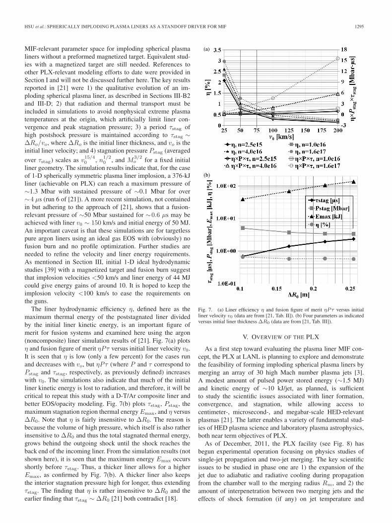
The liner hydrodynamic efficiency η, defined here as themaximum thermal energy of the poststagnated liner dividedby the initial liner kinetic energy, is an important figure ofmerit for fusion systems and examined here using the argon(noncomposite) liner simulation results of [21]. Fig. 7(a) plotsη and fusion figure of merit ηPτ versus initial liner velocity v0.It is seen that η is low (only a few percent) for the cases runand decreases with vo, but ηPτ (where P and τ correspond toPstag and τstag, respectively, as previously defined) increaseswith v0. The simulations also indicate that much of the initialliner kinetic energy is lost to radiation, and therefore, it will becritical to repeat this study with a D-T/Ar composite liner andbetter EOS/opacity modeling. Fig. 7(b) plots τstag, Pstag, themaximum stagnation region thermal energy Emax, and η versusΔR0. Note that η is fairly insensitive to ΔR0. The reason isbecause the volume of high pressure, which itself is also ratherinsensitive to ΔR0 and thus the total stagnated thermal energy,grows behind the outgoing shock until the shock reaches theback end of the incoming liner. From the simulation results (notshown here), it is seen that the maximum energy Emax occursshortly before τstag. Thus, a thicker liner allows for a higherEmax, as confirmed by Fig. 7(b). A thicker liner also keepsthe interior stagnation pressure high for longer, thus extendingτstag. The finding that η is rather insensitive to ΔR0 and theearlier finding that τstag ∼ ΔR0 [21] both contradict [18].
Fig. 7. (a) Liner efficiency η and fusion figure of merit ηPτ versus initialliner velocity v0 (data are from [21, Tab. II]). (b) Four parameters as indicatedversus initial liner thickness ΔR0 (data are from [21, Tab. III]).
V. OVERVIEW OF THE PLX
As a first step toward evaluating the plasma liner MIF con-cept, the PLX at LANL is planning to explore and demonstratethe feasibility of forming imploding spherical plasma liners bymerging an array of 30 high Mach number plasma jets [3].A modest amount of pulsed power stored energy (∼1.5 MJ)and kinetic energy of ∼10 kJ/jet, as planned, is sufficientto study the scientific issues associated with liner formation,convergence, and stagnation, while allowing access tocentimeter-, microsecond-, and megabar-scale HED-relevantplasmas [21]. The latter enables a variety of fundamental stud-ies of HED plasma science and laboratory plasma astrophysics,both near term objectives of PLX.
As of December, 2011, the PLX facility (see Fig. 8) hasbegun experimental operation focusing on physics studies ofsingle-jet propagation and two-jet merging. The key scientificissues to be studied in phase one are 1) the expansion of thejet due to adiabatic and radiative cooling during propagationfrom the chamber wall to the merging radius Rm, and 2) theamount of interpenetration between two merging jets and theeffects of shock formation (if any) on jet temperature and

1296 IEEE TRANSACTIONS ON PLASMA SCIENCE, VOL. 40, NO. 5, MAY 2012
Fig. 8. Photograph of the PLX vacuum chamber (9′ diameter) at LANL(Nov. 30, 2011), where single plasma jet experiments are underway. In theforeground are capacitor banks for the first two plasma guns.
compressibility. An eight-chord interferometer [65] is beingused to measure the chord-averaged density at different jetpropagation positions and the Abel-inverted density profiles inone plane of the jet transverse to the propagation direction. Avisible and infrared spectroscopy system is being used in coor-dination with atomic physics modeling to evaluate the densityand temperature evolution of the jet plasma as it propagatesand expands. A laser-based Schlieren system that is sensitive togradients in plasma density will be employed to image shockformation and evolution in the two-jet merging experiments.PLX diagnostics are described in more detail elsewhere [66].Detailed diagnostic setup geometries have been utilized to gen-erate synthetic interferometer and spectroscopy data based onLSP and Nautilus simulation results of single-jet propagationand two-jet merging. Comparisons with experimental data areunderway.
Phase two of the experiment (planned for 2013, subject toavailable funding) will use 30 guns to investigate sphericalplasma liner formation, convergence, and stagnation. Key sci-entific issues to be studied in phase two include the following:1) peak pressure at stagnation as a function of initial jet param-eters; 2) effects of liner nonuniformity on convergence and stag-nation; and 3) stagnation and poststagnation liner dynamics. Forthe higher densities and temperatures expected in phase two,a vacuum ultraviolet spectroscopy system along with soft X-ray bolometry will be used to estimate the peak densities andtemperatures of the stagnated liner [66].
VI. SUMMARY
Plasma liner MIF is a standoff embodiment of MIF withmany potentially attractive features for a fusion reactor. Anupdated concept-level description of plasma liner MIF is de-scribed in this paper. It is proposed to magnetize the D-T fueljust prior to peak compression via laser generated beat wavecurrent drive, a technique that has been demonstrated experi-mentally at lower tokamak-relevant densities. Plasma liner MIFis intended to take advantage of many reactor-friendly features,including the use of a standoff driver to potentially increaseshot repetition rate and improve cost-of-electricity economicsas well as compatibility with integrated liquid first wall andtritium breeding approaches.
Theory and modeling efforts over the past few years haveimproved the understanding of the evolution of merging plasmajets and imploding plasma liners and have explored noveltechniques such as the use of shaped liners to optimize thefusion-relevant performance of imploding plasma liners. Theseefforts have focused attention on key open scientific issues tobe ultimately resolved by experiment, such as the beneficialradiative cooling of jets resulting in an increase rather thandecrease in Mach number during jet propagation, the details ofshock formation (if any) during jet merging and whether thereis any substantial heating and Mach number downshift, lineruniformity, and material mix during convergence that couldpotentially degrade the peak pressure and temperature at stag-nation, and the poststagnation dynamics of an imploded plasmaliner that determine the confinement time and, ultimately, thefusion performance of a plasma liner MIF system. State-of-the-art 3-D radiation-MHD simulations of a full plasma liner MIFimplosion are still needed for the best possible predictions ofachievable fusion energy gain and for refining the concept.
The PLX at LANL plans to explore and demonstrate the fea-sibility of forming an imploding plasma liner via the mergingof 30 plasma jets in spherically convergent geometry. As ofDecember 2011, PLX has begun experimental operation, withinitial campaigns focusing on scientific issues relating to single-jet propagation and two-jet merging. Subsequently, starting in2013, 30 jet experiments on PLX will focus on studying linerformation, convergence, and stagnation with expected peakpressures of 1 Mbar sustained for order 1 μs. In the near term,PLX will enable a unique scientific platform for fundamentalstudies of spherically imploded HED plasmas by generatingcentimeter-, microsecond-, and megabar-scale plasmas, and inthe longer term, it could provide a platform to further exploreand develop the plasma liner MIF concept.
ACKNOWLEDGMENT
The authors would like to thank Dr. Y. C. F. Thio forencouragement, extensive discussions, and sharing initial 1-Dhydrodynamic simulation results on fusion energy gain for theplasma liner MIF concept. The authors would also like to thankall their collaborators at LANL, HyperV Technologies, Uni-versity of Alabama in Huntsville, University of New Mexico,FAR-TECH, Voss Scientific, Prism Computational Sciences,Tech-X, University of California, Davis, and University ofChicago.

HSU et al.: SPHERICALLY IMPLODING PLASMA LINERS AS A STANDOFF DRIVER FOR MIF 1297
REFERENCES
[1] I. R. Lindemuth and R. C. Kirkpatrick, “Parameter space for magnetizedfuel targets in inertial confinement fusion,” Nucl. Fusion, vol. 23, no. 3,pp. 263–284, Mar. 1983.
[2] R. C. Kirkpatrick, I. R. Lindemuth, and M. S. Ward, “Magnetized targetfusion: An overview,” Fusion Technol., vol. 27, pp. 201–214, 1995.
[3] S. C. Hsu, F. D. Witherspoon, J. T. Cassibry, and M. A. Gilmore,“Overview of the plasma liner experiment,” in Proc. Bull. Amer. Phys.Soc., 2011, vol. 56, p. 307.
[4] I. R. Lindemuth, R. E. Reinovsky, R. E. Chrien, J. M. Christian,C. A. Ekdahl, J. H. Goforth, R. C. Haight, G. Idzorek, N. S. King,R. C. Kirkpatrick, R. E. Larson, G. L. Morgan, B. W. Olinger, H. Oona,P. T. Sheehey, J. S. Shlachter, R. C. Smith, L. R. Veeser, B. J. Warthen,S. M. Younger, V. K. Chernyshev, V. N. Mokhov, A. N. Demin,Y. N. Dolin, S. F. Garanin, V. A. Ivanov, V. P. Korchagin, O. D. Mikhailov,I. V. Morozov, S. V. Pak, E. S. Pavlovskii, N. Y. Seleznev, A. N. Skobelev,G. I. Volkov, and V. A. Yakubov, “Target plasma formation for magneticcompression/magnetized target fusion,” Phys. Rev. Lett., vol. 75, no. 10,pp. 1953–1956, Sep. 1995.
[5] T. Intrator, S. Y. Zhang, J. H. Degnan, I. Furno, C. Grabowski, S. C. Hsu,E. L. Ruden, P. G. Sanchez, J. M. Taccetti, M. Tuszewski, W. J. Waganaar,and G. A. Wurden, “A high density field reversed configuration (FRC)target for magnetized target fusion: First internal profile measurementsof a high density FRC,” Phys. Plasmas, vol. 11, no. 5, pp. 2580–2585,May 2004.
[6] M. Laberge, “Experimental results for an acoustic driver for MTF,”J. Fusion Energy, vol. 28, no. 2, pp. 179–182, Jun. 2009.
[7] G. Votroubek and J. Slough, “The plasma liner compression experiment,”J. Fusion Energy, vol. 29, no. 6, pp. 571–576, Dec. 2010.
[8] Y. C. F. Thio, E. Panarella, R. C. Kirkpatrick, C. E. Knapp,F. Wysocki, P. Parks, and G. Schmidt, “Magnetized target fusion in aspheroidal geometry with standoff drivers,” in Proc. 2nd Int. Symp.—Current Trends International Fusion Research, E. Panarella, Ed., 1999,p. 113.
[9] Y. C. F. Thio, C. E. Knapp, R. C. Kirkpatrick, R. E. Siemon, andP. J. Turchi, “A physics exploratory experiment on plasma liner forma-tion,” J. Fusion Energy, vol. 20, no. 1/2, pp. 1–11, Jun. 2001.
[10] C. E. Knapp, “An implicit smooth particle hydrodynamic code,” Ph.D.dissertation, Univ. New Mexico, Albuquerque, NM, 2000.
[11] Y. C. F. Thio, J. T. Cassibry, and T. E. Markusic, “Pulsed electromagneticacceleration of plasmas,” presented at the 38th AIAA/ASME/SAE/ASEEJoint Propulsion Conf. Exhibit, Indianapolis, IN, Jul. 7–10, 2002, PaperAIAA-2002-3803.
[12] J. T. Cassibry, Y. C. F. Thio, and S. T. Wu, “Two-dimensional axisym-metric magnetohydrodynamic analysis of blow-by in a coaxial plasmaaccelerator,” Phys. Plasmas, vol. 13, no. 5, pp. 053101-1–053101-13,May 2006.
[13] F. D. Witherspoon, S. Brockington, A. Case, S. J. Messer, L. Wu,R. Elton, S. C. Hsu, J. T. Cassibry, and M. A. Gilmore, “Development ofminirailguns for the plasma liner experiment,” in Proc. Bull. Amer. Phys.Soc., 2011, vol. 56, p. 311.
[14] F. D. Witherspoon, A. Case, S. J. Messer, R. Bomgardner, jr.,M. W. Phillips, S. Brockington, and R. Elton, “A contoured gap coaxialplasma gun with injected plasma armature,” Rev. Sci. Instrum., vol. 80,no. 8, p. 083506, Aug. 2009.
[15] A. Case, S. Messer, R. Bomgardner, and F. D. Witherspoon, “Interferom-eter density measurements of a high-velocity plasmoid,” Phys. Plasmas,vol. 17, no. 5, p. 053503, May 2010.
[16] W. Liu and S. C. Hsu, “Ideal magnetohydrodynamic simulations of un-magnetized dense plasma jet injection into a hot strongly magnetizedplasma,” Nucl. Fusion, vol. 51, no. 7, p. 073026, Jul. 2011.
[17] S. C. Hsu, “Technical summary of the first U.S. plasma jet workshop,”J. Fusion Energy, vol. 28, no. 3, pp. 246–257, Sep. 2009.
[18] P. B. Parks, “On the efficacy of imploding plasma liners for magnetizedfusion target compression,” Phys. Plasmas, vol. 15, no. 6, p. 062506,Jun. 2008.
[19] D. R. Welch, D. V. Rose, M. E. Cuneo, R. B. Campbell, andT. A. Mehlhorn, “Integrated simulation of the generation and transportof proton beams from laser-target interaction,” Phys. Plasmas, vol. 13,no. 6, p. 063105, Jun. 2006.
[20] [Online]. Available: http://www.prism-cs.com[21] T. J. Awe, C. S. Adams, J. S. Davis, D. S. Hanna, S. C. Hsu, and
J. T. Cassibry, “One-dimensional radiation-hydrodynamic scaling studiesof imploding spherical plasma liners,” Phys. Plasmas, vol. 18, no. 7,p. 072705, Jul. 2011.
[22] R. J. Kanzleiter, W. L. Atchison, R. L. Bowers, R. L. Fortson,J. A. Guzik, R. T. Olson, J. L. Stokes, and P. J. Turchi, “Using pulsed
power for hydrodynamic code validation,” IEEE Trans. Plasma Sci.,vol. 30, no. 5, pp. 1755–1763, Oct. 2002.
[23] J. J. Monaghan, “Smoothed particle hydrodynamics,” Ann. Rev. Astron.Astrophys., vol. 30, pp. 543–574, Sep. 1992.
[24] C. A. Wingate and R. F. Stellingwerf, “Smooth particle hydrodynamics—The sphynx and SPHC codes,” Los Alamos Nat. Lab., Los Alamos, NM,Tech. Rep. LA-UR-93-1938, 1993.
[25] J. T. Cassibry, M. D. Stanic, T. J. Awe, D. S. Hanna, J. S. Davis,S. C. Hsu, and F. D. Witherspoon, “Theory and modeling of the plasmaliner experiment,” in Proc. Bull. Amer. Phys. Soc., 2010, vol. 55, p. 359.
[26] C. Thoma, D. R. Welch, R. E. Clark, N. Bruner, J. J. MacFarlane, andI. E. Golovkin, “Two-fluid electromagnetic simulations of plasma-jet ac-celeration with detailed equation-of-state,” Phys. Plasmas, vol. 18, no. 10,p. 103507, Oct. 2011.
[27] J. Loverich and A. Hakim, “Two-dimensional modeling of ideal mergingplasma jets,” J. Fusion Energy, vol. 29, no. 6, pp. 532–539, Dec. 2010.
[28] R. P. Drake, “The design of laboratory experiments to producecollisionless shocks of cosmic relevance,” Phys. Plasmas, vol. 7, no. 77,pp. 4690–4698, Nov. 2000.
[29] “Basic research needs for high energy density laboratory physics—Reportof the DOE Workshop on HEDLP Research Needs,” U.S. Dept. Energy,Washington, DC, Nov. 15–18, 2009.
[30] M. M. Basko, A. J. Kemp, and J. M. ter Vehn, “Ignition conditions formagnetized target fusion in cylindrical geometry,” Nucl. Fusion, vol. 40,no. 1, pp. 59–68, Jan. 2000.
[31] R. H. Lovberg and C. L. Daily, “Large inductive thruster performancemeasurement,” AIAA J., vol. 20, no. 7, pp. 971–977, Jul. 1982.
[32] D. E. Johnson and D. P. Bauer, “The effect of rail resistance onrailgun efficiency,” IEEE Trans. Magn., vol. 25, no. 1, pp. 271–276,Jan. 1989.
[33] I. R. Lindemuth and R. E. Siemon, “The fundamental parameter spaceof controlled thermonuclear fusion,” Amer. J. Phys., vol. 77, no. 5,pp. 407–416, May 2009.
[34] S. A. Slutz, M. C. Herrmann, R. A. Vesey, A. B. Sefkow, D. B. Sinars,D. C. Rovang, K. J. Peterson, and M. E. Cuneo, “Pulsed-power-drivencylindrical liner implosions of laser preheated fuel magnetized with anaxial field,” Phys. Plasmas, vol. 17, no. 5, p. 056303, May 2010.
[35] P. Y. Chang, P. Y. Chang, G. Fiksel, M. Hohenberger, J. P. Knauer,R. Betti, F. J. Marshall, D. D. Meyerhofer, F. H. Séguin, andR. D. Petrasso, “Fusion yield enhancement in magnetized laser-drivenimplosions,” Phys. Rev. Lett., vol. 107, no. 3, pp. 035006-1–035006-4,Jul. 2011.
[36] J. Slough, S. Andreason, H. Gota, C. Pihl, and G. Votroubek, “The pulsedhigh density experiment: Concept, design, and initial results,” J. FusionEnergy, vol. 26, no. 1/2, pp. 199–205, Jun. 2007.
[37] A. Y. Chirkov and S. V. Ryzhkov, “The plasma jet/laser driven com-pression of compact plasmoids to fusion conditions,” J. Fusion Energy,vol. 31, no. 1, pp. 7–12, Feb. 2012.
[38] S. F. Garanin, “The MAGO system,” IEEE Trans. Plasma Sci., vol. 26,no. 4, pp. 1230–1238, Aug. 1998.
[39] Y. C. F. Thio, private communication, 2011.[40] M. M. Marinak, R. E. Tipton, O. L. Landen, T. J. Murphy, P. Amendt,
S. W. Haan, S. P. Hatchett, C. J. Keane, R. McEachern, and R. Wallace,“Three-dimensional simulations of NOVA high growth factor capsuleimplosion experiments,” Phys. Plasmas, vol. 3, no. 5, pp. 2070–2076,May 1996.
[41] A. Ciardi, S. V. Lebedev, A. Frank, E. G. Blackman, J. P. Chittenden,C. J. Jennings, D. J. Ampleford, S. N. Bland, S. C. Bott, J. Rapley,G. N. Hall, F. A. Suzuki-Vidal, A. Marocchino, T. Lery, and C. Stehle,“The evolution of magnetic tower jets in the laboratory,” Phys. Plasmas,vol. 14, no. 5, pp. 056501-1–056501-10, May 2007.
[42] P. J. Turchi, N. F. Roderick, J. H. Degnan, M. H. Frese, andD. J. Amdahl, “Review of plasma gun techniques for fusion at megagaussenergy densities,” IEEE Trans. Plasma Sci., vol. 38, no. 8, pp. 1864–1873,Aug. 2010.
[43] J. R. Thompson, N. I. Bogatu, S. A. Galkin, J. S. Kim, D. R. Welch,C. Thoma, J. J. MacFarlane, F. D. Witherspoon, J. T. Cassibry, T. J. Awe,and S. C. Hsu, “Plasma jet propagation and stability modeling for theplasma liner experiment,” in Proc. Bull. Amer. Phys. Soc., 2010, vol. 55,p. 360.
[44] C. Thoma, private communication, 2011.[45] J. D. Huba, NRL Plasma Formulary, 2009.[46] R. Samulyak, P. Parks, and L. Wu, “Spherically symmetric simulation of
plasma liner driven magnetoinertial fusion,” Phys. Plasmas, vol. 17, no. 9,p. 092702, Sep. 2010.
[47] J. T. Cassibry, M. Stanic, R. Hatcher, S. Hsu, D. Witherspoon, M. Gilmore,and W. Luo, “The tendency of plasma liners formed by hypersonic jets to

1298 IEEE TRANSACTIONS ON PLASMA SCIENCE, VOL. 40, NO. 5, MAY 2012
evolve toward good spherical symmetry during implosion,” in Proc. Bull.Amer. Phys. Soc., 2011, vol. 56, p. 311.
[48] J. T. Cassibry, M. Stanic, S. C. Hsu, S. I. Abarzhi, and F. D. Witherspoon,“Tendency of spherically imploding plasmas liners formed by merg-ing plasma jets to evolve toward spherical symmetry,” submitted forpublication.
[49] M. N. Rosenbluth and C. S. Liu, “Excitation of plasma waves by two laserbeams,” Phys. Rev. Lett., vol. 29, no. 11, pp. 701–705, Sep. 1972.
[50] A. N. Kaufman and B. I. Cohen, “Nonlinear interaction of electromagneticwaves in a plasma density gradient,” Phys. Rev. Lett., vol. 30, no. 26,pp. 1306–1309, Jun. 1973.
[51] J. H. Rogers and D. Q. Hwang, “Measurements of beat-wave-acceleratedelectrons in a toroidal plasma,” Phys. Rev. Lett., vol. 68, no. 26, pp. 3877–3880, Jun. 1992.
[52] F. Liu, R. Horton, D. Q. Hwang, R. Evans, Z. F. Huang, and A. Semet,“Laser-driven beat-wave current drive in an unmagnetized plasma,” pre-sented at the 38th European Physical Society Conf. Plasma Physics,Strasbourg, France, 2011, paper P2.023.
[53] D. D. Ryutov, “Adiabatic compression of a dense plasma ‘mixed’ withrandom magnetic fields,” Fus. Sci. Tech., vol. 56, no. 4, pp. 1489–1494,Nov. 2009.
[54] J. T. Cassibry, R. J. Cortez, S. C. Hsu, and F. D. Witherspoon, “Estimatesof confinement time and energy gain for plasma liner driven magnetoiner-tial fusion using an analytic self-similar converging shock model,” Phys.Plasmas, vol. 16, no. 11, p. 112707, Nov. 2009.
[55] G. Kagan, X. Tang, S. C. Hsu, and T. J. Awe, “Bounce-free sphericalhydrodynamic implosion,” Phys. Plasmas, vol. 18, no. 12, p. 120702,Dec. 2011.
[56] R. Courant and K. O. Friedrichs, Supersonic Flow and Shock Waves.Berlin, Germany: Springer-Verlag, 1976.
[57] R. L. Miller, “Perspectives on magnetized target fusion power plants,”J. Fusion Energy, vol. 26, no. 1/2, pp. 119–121, Jun. 2007.
[58] R. W. Moses, R. A. Krakowski, and R. L. Miller, “A conceptual designof the fast-liner reactor (FLR) for fusion power,” Los Alamos Nat. Lab.,Los Alamos, NM, Tech. Rep. LA-7686-MS, 1979.
[59] R. L. Miller, “Liner-driven pulsed magnetized target fusion power plant,”Fusion Sci. Technol., vol. 52, no. 3, pp. 427–431, Oct. 2007.
[60] R. L. Miller, private communication, 2011.[61] D. Weidenheimer, D. Morton, G. James, D. Giorgi, T. Navapanich,
D. Knudsen, and R. Knight, “Scaled-up LGPT (laser gated andpumped thyristor) devices at KrF IFE (inertial fusion energy) operatingparameters,” in Conf. Rec. 27th Int. Power Modulator Symp., 2006,pp. 201–206.
[62] J. D. Sethian, M. Friedman, J. L. Giuliani, R. H. Lehmberg,S. P. Obenschain, P. Kepple, M. Wolford, F. Hegeler, S. B. Swanekamp,D. Weidenheimer, D. Welch, D. V. Rose, and S. Searles, “Electron beampumped KrF lasers for fusion energy,” Phys. Plasmas, vol. 10, no. 5,pp. 2142–2146, May 2003.
[63] R. W. Moir, “The high-yield lithium-injection fusion-energy (HYLIFE)-II inertial fusion energy (IFE) power plant concept and implications forIFE,” Phys. Plasmas, vol. 2, no. 6, pp. 2447–2452, Jun. 1995.
[64] P. M. Bardet, B. F. Supiot, P. F. Peterson, and O. Savas, “Liquid vortexshielding for fusion energy applications,” Fusion Sci. Technol., vol. 47,no. 4, pp. 1192–1196, May 2005.
[65] E. C. Merritt, A. G. Lynn, M. A. Gilmore, and S. C. Hsu, “Multi-chordfiber-coupled interferometer with a long coherence length laser,” Rev. Sci.Instrum., accepted for publication, 2012.
[66] A. G. Lynn, E. Merritt, M. Gilmore, S. C. Hsu, F. D. Witherspoon, andJ. T. Cassibry, “Diagnostics for the plasma liner experiment,” Rev. Sci.Instrum., vol. 81, no. 10, p. 10E115, Oct. 2010.
S. C. Hsu, photograph and biography not available at the time of publication.
T. J. Awe, photograph and biography not available at the time of publication.
S. Brockington, photograph and biography not available at the time ofpublication.
A. Case, photograph and biography not available at the time of publication.
J. T. Cassibry, photograph and biography not available at the time ofpublication.
G. Kagan, photograph and biography not available at the time of publication.
S. J. Messer, photograph and biography not available at the time ofpublication.
M. Stanic, photograph and biography not available at the time of publication.
X. Tang, photograph and biography not available at the time of publication.
D. R. Welch, photograph and biography not available at the time of publication.
F. D. Witherspoon, photograph and biography not available at the time ofpublication.