spg mitteilungen communications de la ssp auszug - … · different accelerator types during the...
TRANSCRIPT

Nr. 45März 2015
SPG MITTEILUNGENCOMMUNICATIONS DE LA SSP
AUSZUG - EXTRAIT
This article has been downloaded from:http://www.sps.ch/fileadmin/articles-pdf/2014/Mitteilungen_Anecdotes_18.pdf
© see http://www.sps.ch/bottom_menu/impressum/
Physics Anecdotes (18)The importance of mechanical clocks or tandem Van de Graaff accelerators for
high-resolution nuclear spectroscopyBernhard Braunecker

37
Communications de la SSP No. 44
Physics Anecdotes (18)The importance of mechanical clocks or tandem Van de Graaff accelerators for
high-resolution nuclear spectroscopyBernhard Braunecker
IntroductionThe following report looks at the history of tandem Van de Graaff accelerators. They were installed worldwide at many universities during the 1960s, and many of them are still in use today, e.g. in medicine, material or space science. Their original application was in high-precision nuclear spectros-copy using mono-energetic beams of heavy ions with ener-gies < 100 MeV, either in a continuous or in a pulsed mode.In Part I we explain why the tandems were ideal for certain studies. However, they also created for us students a par-ticular social atmosphere. Hard work in technology - seldom in physics! - gave young physicists the confidence to scruti-nise the socio-political structures of the time in the academic world.In Part II (which will appear in one of the next "SPS Com-munications") we show that driving an accelerator needed a profound understanding of beam generation and accelera-tion physics, even if the machine was a commercial product. As a counter example we illustrate how wrong handling of the operators led to a serious fire damage of the Tandem ion source at Erlangen University.
Part I
Different Accelerator TypesDuring the early years most tandems were installed and maintained by HVEC in Burlington, USA. At the same time the development of the large electron and proton synchro-trons and linear accelerators was largely left to the pow-erful machines which recently succeeded in proving the existence of the Higgs particle at CERN. Their main dif-ference from their smaller relatives, the tandems, was that the big machines produced and produce huge amounts of data, from which sophisticated algorithms identify those few events predicted by theory. Tandems, on the other hand, were operated in a more deterministic way to systemati-cally probe nuclear fine structures. To this end one could choose the most appropriate particles, their energy, and in certain cases even their energy spread. Hydrogen and deu-terium beams could be accelerated as polarised particles. One could acquire a beam in a continuous mode to meas-ure absorption/scattering cross-sections or alternatively in a pulsed mode to analyse the time-dependent reactions of the target nucleus under study.
Technical Features of TandemsTandems were characterised by some outstanding param-eters.
(1) A large variety of heavy ions, apart from H and D, which could be accelerated: He, N, C, O, Si, Cl, P, S,.., U, including expensive isotopes like 13C or 37Cl.
(2) Extremely good energy stability together with an en-ergy spread of only a few keV, allowing fine-tuning of energy and ensuring constant beam intensities at the target.
(3) Excellent beam quality (spatial coherence) for loss-less beam transfer, narrow spot focusing and precise shaping of the intensity profile.
(4) The possibility of generating polarised H and D parti-cles and keeping the degree of polarisation from the ion source to the targets to analyse nuclear spin-spin interactions.
(5) Tunable generation of nanosecond pulses for dynam-ical studies such as nuclear decay processes after Coulomb excitation or time-of-flight measurements to identify fission products after nuclear reactions.
Social AspectsThe experimental work at and around the accelerator was challenging, but also stimulating. Since the accelerator was operated by a professional service team only during the daytime, the tandem had to be run at night by physicists. Thus every student had to learn a number of technologies to obtain their tandem driving licence. This training on the job helped them considerably with their own experiments and, more importantly, created a unique team spirit. Principle of OperationThe central part of the tandem Van de Graaff (Figure 1) was the high voltage terminal which was loaded by a moving belt charger to positive voltages between 6 and 10 MV, depend-ing on the tandem type, and in some special cases even up to +25 MV. The terminal was placed inside a pressure ves-sel some 10 m to 25 m in length with a diameter of several metres and filled with gas of 6 to 8 atm, either nitrogen or, preferably, SF6 to minimise 'tank sparks'. These were unpre-dictable flashes from the terminal to the tank walls, which sounded like hammer strokes and were acoustically moni-tored by microphones. It was a favourite prank to hit the tank during long night sessions with a rubber mallet to wake up the colleague at the operator desk, who would panic and immediately drive down the terminal voltage.Two vacuum tubes for the beam transport connected the terminal to the tandem's entry and exit flanges, both lying at ground potential. Each tube consisted of a series of glued ceramic segments with metal electrodes (some were grid-ded), which were connected by a resistor chain from the terminal to the ground. Then both column currents caused well-defined potential distributions along both tubes, which not only accelerated the ions, but also focused the incom-ing collimated beam onto the terminal, and, vice versa, pro-duced a collimated beam at the tandem exit.
Negative to Positive IonsThe conversion of the arriving negative ions to positive ions was accomplished by electron stripping reactions within a gas target inside the terminal. However, gas targets were soon replaced by targets of thin carbon layers, which had not only better conversion efficiency but also reduced the occurrence of dangerous 'tube sparks'. They also defined

38
SPG Mitteilungen Nr. 44
exactly where the positive ions were generated, knowledge needed for correct adjustment of the beam optics at the high end. Since the lifetime of the carbon targets was limited to a few hours or days, however, depending on the operation, about twenty of them were mounted on a revolving wheel by us physicists. This target holder was driven by a mechani-cal clock and switched via an insulating nylon string from outside the tank.The positive ions were post-accelerated down to ground po-tential. If, for example, we injected O- into the terminal at +8 MV, where the stripping conversion to O5+ was dominant, the second acceleration led to the final beam energy of 48 MeV.
Beam OpticsIon optical components were needed to guide and manipu-late the beam from the ion source to the experimental set-ups in the target halls.Beam lenses: focusing elements at the low end side were electrostatic collimator or Einzel lenses consisting of two, respective three cylindrical electrodes, where in the latter case the first and the third ones were at the same potential, whereas the potential of the second one was changeable in order to vary the focal length. The combination of many cylindrical segments at different potential for focusing has already been mentioned. When the beam was deflected by a magnet either to bend the ions into another direction or for momentum analysis, the beam component normal to the magnet field lines was also focused, and the component in field direction was defocused. The focusing / defocusing properties of deflecting magnets could be further influenced by the shape and the orientation of the pole shoes. To com-pensate for the resulting astigmatism or in some cases to enforce it (when focusing on a slit was required) quadrupole lenses (electrostatic for low energy beams and magneto-static for high energy beams) were installed at both sides
of the tandem. The spherical and the astigmatic focusing power could be varied.Beam steerers: these were condensator plates for shifting the beam in both lateral directions. They were installed out-side and inside the tandem to treat without loss the beam through both acceleration tubes and from the accelerator to the target halls. Operators needed some experience to steer the beam correctly through all the optical elements, slits and magnets. Wrong steering could cause the beam to hit the metal electrodes in the ceramic tube segments and thus trigger dangerous 'tube sparks', which could result in 'burned-in' traces in the ceramic insulators. If this happened too often, one had to short-circuit the damaged tube seg-ment, which reduced the focusing properties of the whole tube. As a last resort one would have to replace the very expensive tube!
MonochromacyThe terminal voltage fluctuations had direct impact on the final ion energy. Even under the best conditions the voltage of several MV varied between 500 and 1,000 V. The main reasons for this were unavoidable material inhomogenei-ties of the rubber impregnation of the charging belt, which stochastically varied the charge current but were periodic with the belt frequency of some Hertz. To stabilise the termi-nal voltage a special 'corona point' module (see Figure 1), placed close to the terminal and sucking off positive charg-es, was connected to the anode of a triode placed outside the tank.The triode current was controlled twice: first, by the signal of a capacitive pick-off detector (CPO) inside the tank, which monitored fast terminal voltage fluctuations and, second, by the difference signal of two electrodes, installed inside the beam tube between both 90° bending magnets. Both electrodes were adjusted to define a narrow slit < 0.5 mm, on which the beam was focused by the optics, i.e. by the
Figure 1: Negative ions are injected, converted to positive ions and post-accelerated
39
Communications de la SSP No. 44
second acceleration tube segments, a magnetic quadrupole lens and the first 90° bending magnet. The magnet field was tuned such that only ions of the desired momentum could pass through the slit. Slower or faster ions consequently hit one of the electrodes and the resulting difference signal changed the triode current and thus the terminal volt-age. The combination of both con-trol mechanisms kept the ion energy fluctuations at few keV.
Pulsing SystemThe pulsing system for the HVEC tandem accelerator at the University of Erlangen was a combination of a pre-injection klystron buncher and a post-acceleration chopper. It was developed to produce pulses of protons, deuterons and es-pecially heavy ions up to mass 16 with pulse widths of some nanoseconds. The beam chopper, installed at the tandem high end (Figure 2), was a beam steerer, driven by a si-nusoidal deflection voltage of about 15 kV amplitude for rf frequencies between 3 and 10 MHz. The electric field swept the beam across a second slit pair, oriented orthogonally to the one used for energy stabilisation, to cut out beam pulses of nanosecond duration. The purpose of the beam buncher, installed at the tandem low end for technical reasons, was to increase the pulse intensity of the chopped beam. It was a two-gap klystron, where the central electrode was modu-lated by a sinusoidal voltage of about 4 kV amplitude and the same chopper frequency. The phase relation between both modulation voltages had to be carefully adjusted and kept constant to sweep the chopped beam exactly across the slit when the pre-bunched ion pulse arrived.
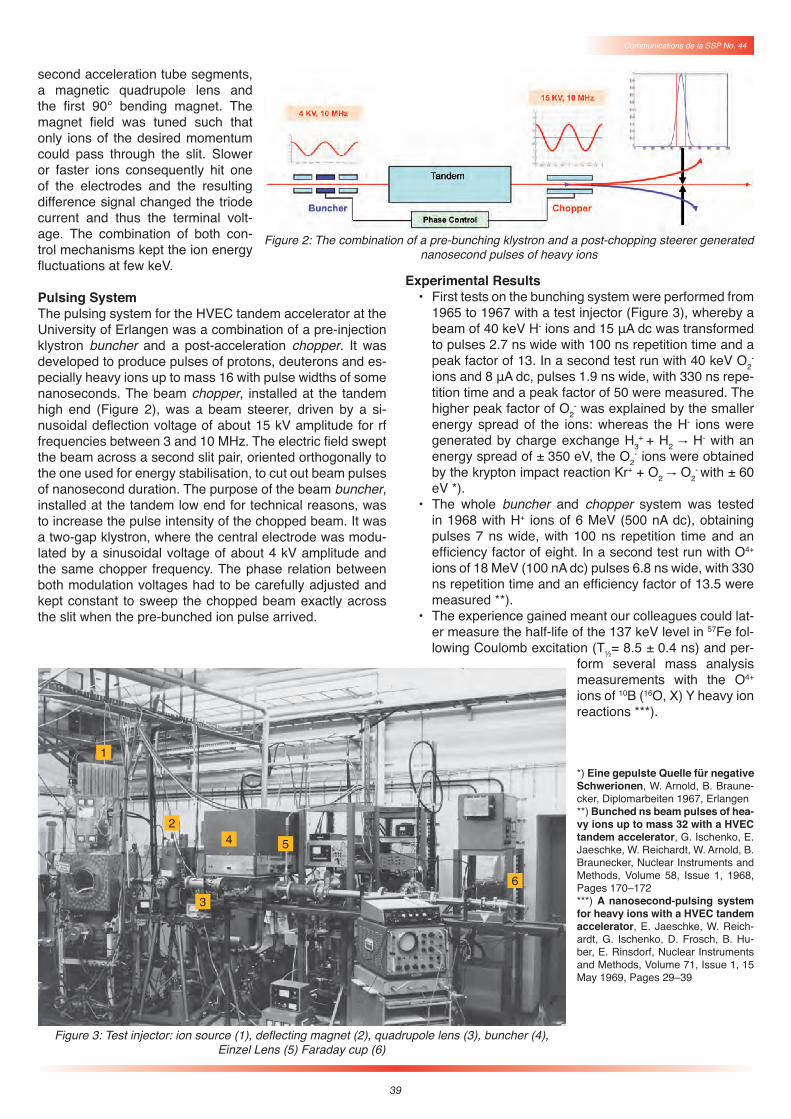
Experimental Results• First tests on the bunching system were performed from
1965 to 1967 with a test injector (Figure 3), whereby a beam of 40 keV H- ions and 15 μA dc was transformed to pulses 2.7 ns wide with 100 ns repetition time and a peak factor of 13. In a second test run with 40 keV O2
- ions and 8 μA dc, pulses 1.9 ns wide, with 330 ns repe-tition time and a peak factor of 50 were measured. The higher peak factor of O2
- was explained by the smaller energy spread of the ions: whereas the H- ions were generated by charge exchange H3
+ + H2 " H- with an energy spread of ± 350 eV, the O2
- ions were obtained by the krypton impact reaction Kr+ + O2 " O2
- with ± 60 eV *).
• The whole buncher and chopper system was tested in 1968 with H+ ions of 6 MeV (500 nA dc), obtaining pulses 7 ns wide, with 100 ns repetition time and an efficiency factor of eight. In a second test run with O4+ ions of 18 MeV (100 nA dc) pulses 6.8 ns wide, with 330 ns repetition time and an efficiency factor of 13.5 were measured **).
• The experience gained meant our colleagues could lat-er measure the half-life of the 137 keV level in 57Fe fol-lowing Coulomb excitation (T½= 8.5 ± 0.4 ns) and per-
form several mass analysis measurements with the O4+ ions of 10B (16O, X) Y heavy ion reactions ***).
*) Eine gepulste Quelle für negative Schwerionen, W. Arnold, B. Braune-cker, Diplomarbeiten 1967, Erlangen**) Bunched ns beam pulses of hea-vy ions up to mass 32 with a HVEC tandem accelerator, G. Ischenko, E. Jaeschke, W. Reichardt, W. Arnold, B. Braunecker, Nuclear Instruments and Methods, Volume 58, Issue 1, 1968, Pages 170–172***) A nanosecond-pulsing system for heavy ions with a HVEC tandem accelerator, E. Jaeschke, W. Reich-ardt, G. Ischenko, D. Frosch, B. Hu-ber, E. Rinsdorf, Nuclear Instruments and Methods, Volume 71, Issue 1, 15 May 1969, Pages 29–39
Figure 2: The combination of a pre-bunching klystron and a post-chopping steerer generated nanosecond pulses of heavy ions
Figure 3: Test injector: ion source (1), deflecting magnet (2), quadrupole lens (3), buncher (4),Einzel Lens (5) Faraday cup (6)
1
2
3
4
6
5