speeding up algorithm for building the stl … · software that can read the stl file, slicing it...
TRANSCRIPT

83 PT 6, 201April 21-19Conference, AMMEInt. ht7Proceedings of the 1
17th International Conference on Applied Mechanics and Mechanical Engineering.
Military Technical College Kobry El-Kobbah,
Cairo, Egypt.
SPEEDING UP ALGORITHM FOR BUILDING THE STL MODEL USING 3D PRINTING
M. Hamoud1, A. I. EL-Wahab2 and A. Barakat3
ABSTRACT Recently, developing 3D printing (3DP) technologies have been substantially increased, because its advantages toward the direct fabricating of 3D physical model from the CAD system. Although several advantages over the subtractive method, there are still many difficulties and problems for building a precise and efficient part. Building time and Accuracy are two important concerns in 3DP. To speed up the building process and improve the accuracy at the same time, an algorithm based on mathematical models will be presented. The algorithm presents variable slicing strategy by adjusting the layer thickness to consider the curvature and flatness of the 3D CAD surfaces, in order to reduce the number of building layers, staircase effect, and consequently decrease the building time and cost. Through this proposed analytical study and the results, the number of layers were saved by 54% that will decrease the building time by the same percentage. KEY WORDS 3D Printing (3DP), Optimum Layer Thickness, Effective Slicing Algorithm, and Standard Transformation Language (STL) File. 1 Assistant Professor, Faculty of Engineering, Helwan University, Cairo, Egypt,
[email protected] 2 Professor, Faculty of Engineering, Helwan University, Cairo, Egypt,
[email protected] 3 Professor, Faculty of Engineering, Helwan University, Cairo, Egypt,

84 PT 6, 201April 21-19Conference, AMMEInt. ht7Proceedings of the 1
NOMENCLATURE A Layer Area (mm2) E12 Facet Edge extended from vertex #1 to vertex # 2 E23 Facet Edge extended from vertex #2 to vertex # 3 E31 Facet Edge extended from vertex #3 to vertex # 4 F Facet coordinates Lt Layer thickness (mm) Ltmax Max. layer thickness(mm) Ltmin Min. layer thickness (mm) MH Max height of the model (mm) N Total number of points in STL file nc Number of coordinate points per layer Nf Total number of facets NL Number of Layers O Orientation angle (degree) P Point coordinates of layer V Vertices coordinates X X- coordinates of STL model Xmax Max. coord. In X direction for STL model Xmin Min. coord. In X direction for STL model Y Y- coordinates of STL model Ymax Max. coord. In Y direction for STL model Ymin Min. coord. In Y direction for STL model Z Z- coordinates of STL model Zmax Max. coord. In Z direction for STL model Zmaxf Max. coord. In Z direction for facet Zmin Min. coord. In Z direction for STL model Zminf Min. coord. In Z direction for facet Zpl Z – value of the slicing plane (mm)
INTRODUCTION Over the last few decades, designers, engineers, and technicians commonly use various computer-assisted technologies to evaluate their products at each stage in the product development cycle. These computer-assisted technologies comprise Computer Aided Design (CAD), Computer Aided Manufacturing (CAM) and Computer Aided Engineering (CAE) [1, 2, 3]. 3D Printing (3DP) belong to the CAD/CAM system that use the additive production method unlike subtractive or forming processes to create the model. In all commercial 3DP processes, the part is fabricated by deposition of layers contoured in a (x-y) plane from the math data eliminating all tooling [4, 5]. 3DP systems are the ones that use additive processes to deliver finished parts directly It is also known as Layered Manufacturing (LM), Rapid Prototyping (RP), Solid Freeform Fabrication (SSF), Material Additive Manufacturing (AM), or Desktop Manufacturing [6]. The major impact of 3DP would be the possibility of fabricating complex parts for end use, prototyping models for surgical planning, and manufacturing implants for medical applications. In addition, it has been widely used in several domains to accelerate, check and validate product design, and implementation of product [7].

85 PT 6, 201April 21-19Conference, AMMEInt. ht7Proceedings of the 1
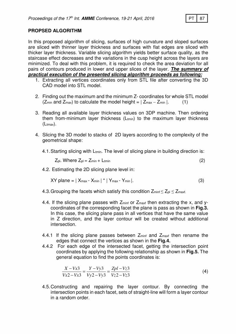
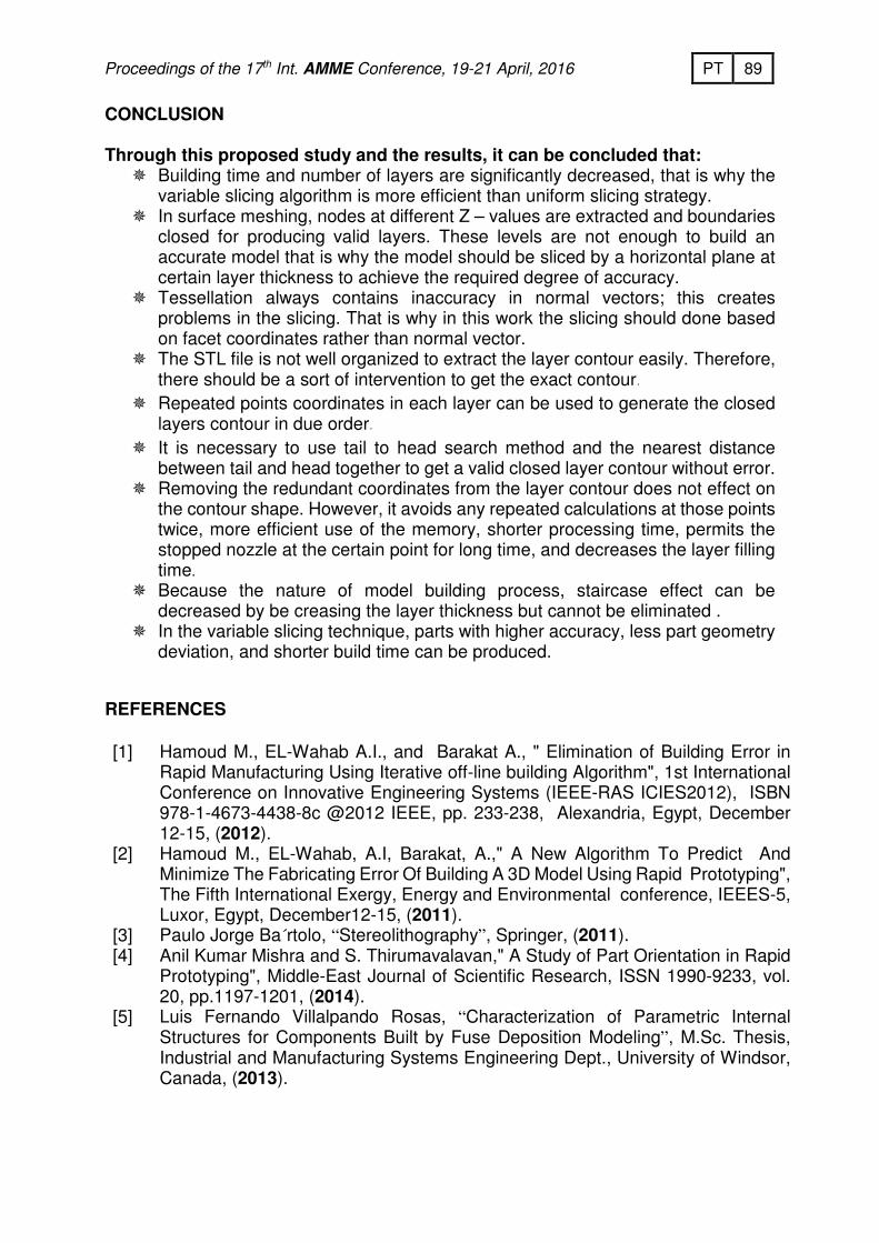
Many material addition techniques are used including Fused Deposition Modeling (FDM), Selective Laser Sintering (SLS), Selective Laser Melting (SLM), Electron Beam Melting (EBM), and Stereolithography (SLA). All techniques shear the same basic process (Fig.1) which start with creating of a 3D CAD solid model, converting the CAD file to STL file format, slicing of the converted file into 2D cross-sectional layers, constructing the model and finally post-processing of the model [8]. Although several advantages 3DP over the subtractive method, there are still many difficulties and problems facing this technology to build a precise and an efficient part. Building time and accuracy are two important concerns in 3DP. To produce a model with low building time , the model slices with the largest layer thickness which case a stair stepping effect (Fig.2) and the vice versa. To speed up the building process and improve the accuracy of the model at the same time, speeding up algorithm with variable slicing strategy based on mathematical models will be presented. The algorithm adjusts the layer thickness to consider the curvature of the surface of the solid model and its sloped edges in the building direction, to reduce the staircase effect, and to decrease the number of layers and consequently decrease the building time and cost. This research will provide guidance and valuable information to the designers and 3D printing users to get an efficient model through the following research benefits. The mathematical models will show the dependency of 3DP model on process parameters, the 3DP users will be guided to make a better decision in fabricating parts before actually making them, the layer thickness will be automatically chosen with little human intervention, the part will be produced with short building time and high accuracy with minimum post processing operation, the machine utilization will be improved, The preparation time will decrease, the productivity of the machine will be increased, the chance of competition will be increased, and the manufacturer will be able to decide whether to use 3DP m/c or CNC m/c to produce the model. LITERATURE RIVIEW
In recent years, investigations have taken up interest in improving part accuracy, error, and in the optimization. Processing accuracy and surface smoothness are important areas studied in 3DP. Accuracy and surface smoothness depend on many factors, such as, the 3DP technique, material, and process parameters used to build the part. Constant slicing is widely used in 3DP systems due to its simplicity in implementation. One of the simplest slicing algorithms for STL files is to intersect all triangles with each z-plane and connect the resulting line segments into closed polygons, one slice at a time. This approach used by Hamoud et. al. [9] that proposes an algorithm to read the STL file, remove the undesired data, extract the required coordinates only and remove the redundant coordinates from the file. A presented algorithm used for controlling the CAD orientate and slicing the oriented model by constant layer thickness. Manmadhachary et. al. [10] developed smoothing algorithm with combination of Interpolation and mesh construction methods for producing an accurate and smoother STL file. The proposed algorithm was implanted on STL file in the study. The STL file was primarily split into slices of equal thickness along the Z-axis direction. Each slice contour data information was created as a

86 PT 6, 201April 21-19Conference, AMMEInt. ht7Proceedings of the 1
Common Layer Interface (CLI) file. These contour data points were increased further improved contour accuracy by Fast Fourier Transform (FFT) method. As well as, these contour data points were used to generate a surface and STL file simultaneously by the Delaunay triangulation method. By applying this novel combination method, the generated STL file accuracy and smoothness were improved when compared to the initial STL file.
Chen et. al. [11] developed a robotic machining system with layer-based algorithms to build large part models. A model represented as a StereoLithography Contour (SLC) file is machined layer by layer. The stock adaptive layer thickness is determined based a visibility pyramid concept. Each stock layer is, in turn, machined by many machining layers. Ma and He [12] presented an adaptive slicing algorithm, which operates directly on a NURBs based CAD surface. A selective hatching strategy was also proposed to reduce the build time by solidifying/depositing kernel regions of the part with the maximum allowable thick layers.
Sabourin et. al. [13] proposed an approach by subdividing the model space into uniform slabs with the maximum thickness acceptably a RP process. Each of these slabs in further divided into thinner layers so the cusp height is within a given tolerance. Xu et.
al. [14] carried out an adaptive slicer in a CAD system to convert the solid model to RP without using the STL file. The slicer application employs a genetic algorithm to find the minimum layer thickness allowed at referenced height with a given cusp height tolerance .
Kulkami and Dutta [15] developed a procedure to determine the variety of sliced thickness for a given part. The staircase effect is analyzed in this paper. Normally, the extra material deposited in RP process is polished by post processing operation for smoother surface. Therefore, the authors classed the approximations into two types of containment. The first one is the positive tolerance .In this case, all staircase effect was considered outside the original model. The second one is the negative tolerance. In this case, all staircase effect was considered inside the original model. From this paper, it can be concluded the adaptive slicing method has more advantages than the uniform slicing model .
Tyberg and Bohn [16] presented an approach for adaptive slicing technique that was used to reduce the building time. In this approach, the individual parts and their features were identified and sliced independently based on the geometry of each part. This approach improves the slicing operation by eliminating most of the slices that do not effectively enhance the overall part surface quality. The previous efforts provided good contributions, but they do not present an analytical method to choose the optimum layer thickness according to the geometrical shape of the CAD model. Furthermore, they presented neither good explanations for different problems nor detailed algorithms to help the researchers make software to study the effect of different parameters in 3DP without the experimental work. The objective of this paper is present an algorithm with an analytical study to build a software that can read the STL file, slicing it by different values of layer thickness in order to speed up the building operation with little deviations between physical and CAD model and eliminate the post processing operations.
87 PT 6, 201April 21-19Conference, AMMEInt. ht7Proceedings of the 1
PROPSED ALGORITHM In this proposed algorithm of slicing, surfaces of high curvature and sloped surfaces are sliced with thinner layer thickness and surfaces with flat edges are sliced with thicker layer thickness. Variable slicing algorithm yields better surface quality, as the staircase effect decreases and the variations in the cusp height across the layers are minimized. To deal with this problem, it is required to check the area deviation for all pairs of contours produced in lower and upper slices of the layer. The summary of practical execution of the presented slicing algorithm proceeds as following:
1. Extracting all vertices coordinates only from STL file after converting the 3D CAD model into STL model.
2. Finding out the maximum and the minimum Z- coordinates for whole STL model (Zmin and Zmax) to calculate the model height = | Zmax – Zmin |. (1)
3. Reading all available layer thickness values on 3DP machine. Then ordering
them from-minimum layer thickness (Ltmin) to the maximum layer thickness (Ltmax).
4. Slicing the 3D model to stacks of 2D layers according to the complexity of the
geometrical shape:
4.1. Starting slicing with Ltmin. The level of slicing plane in building direction is:
Zpl. Where Zpl = Zmin + Ltmin (2)
4.2. Estimating the 2D slicing plane level in: XY plane = | Xmax - Xmin | * | Ymax - Ymin |. (3)
4.3. Grouping the facets which satisfy this condition Zminf ≤ Zpl ≤ Zmaxf. 4.4. If the slicing plane passes with Zminf or Zmaxf then extracting the x, and y-
coordinates of the corresponding facet the plane is pass as shown in Fig.3. In this case, the slicing plane pass in all vertices that have the same value in Z direction, and the layer contour will be created without additional intersection.
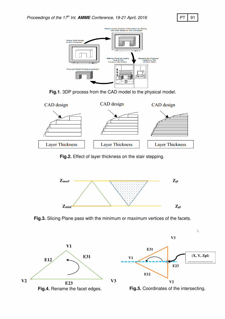
4.4.1 If the slicing plane passes between Zminf and Zmaxf then rename the
edges that connect the vertices as shown in the Fig.4. 4.4.2 For each edge of the intersected facet, getting the intersection point
coordinates by applying the following relationship as shown in Fig.5. The general equation to find the points coordinates is:
32
3
32
3
32
3
VzVz
VzZpl
VyVy
VyY
VxVx
VxX
−
−
=
−
−
=
−
−
(4)
4.5. Constructing and repairing the layer contour. By connecting the
intersection points in each facet, sets of straight-line will form a layer contour in a random order.

88 PT 6, 201April 21-19Conference, AMMEInt. ht7Proceedings of the 1
4.6. Removing the redundant points from the repaired layer contour.
4.7. Calculate the area (A (k)) of the layer contour from the bottom of the model by using the following relationship:
(k) = 1/2 |∑ ���� ∗ �� + � − ��� + ∗ ��� ����
��� | (5)
where k is the current layer contour, xi and yi are the coordinates initial and ending points of the line segments of the polygon in the layer.
4.8. Calculating the area (A (k+1)) of the next layer contour in building direction. The value of Zpl will be:
Zpl = Zpl + Ltmin. (6)
4.9. Compare the two areas with each other. If there is a deviation |A (k) - A (k+1)| ≠ 0, then applying the steps from 4.1 to 4.8. Otherwise, put
Zpl = Zpl + Ltmax. (7)
4.10. The algorithm gives the number of slicing layers and the corresponding layer thickness for each region of the model.
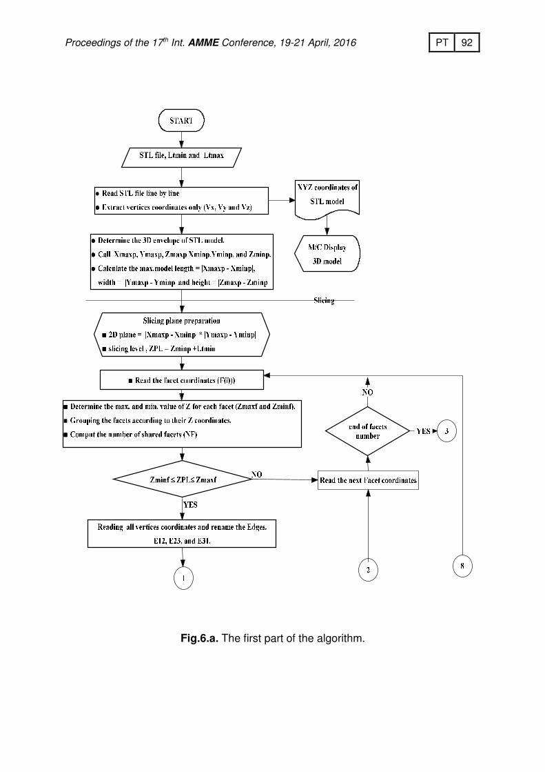
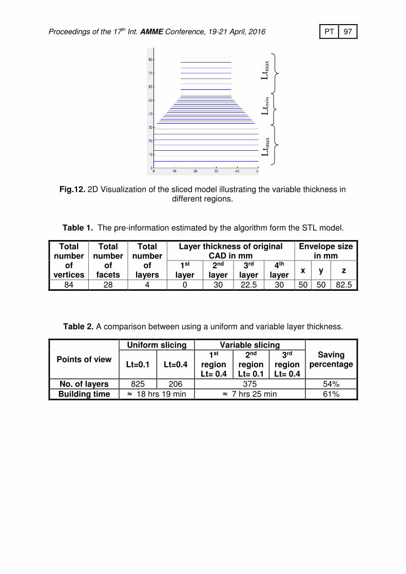
The Off-line Variable Slicing Algorithm flowchart is shown in Fig. 6. SYSTEM IMPLEMENTATION AND CASE STUDY Fig.7. shows the 3D CAD solid model designed in Solid Edge ST4 and exported as STL file to be built on 3DP m/c that has max. and min layer thickness equal to 0.4 and 0.1 mm respectively. This model is chosen to verify the methodology dedicated to slice a part while the staircase effect is minimized. The part is divided to three regions according to its change in cross sections among the building direction (Z – axis). RESULTS The algorithm starts to extract all coordinates in STL file and save it in ASCII file, then display the STL model in 3D view for verification as shown in Fig.8. The pre-information calculated by the algorithm, such as number of points, number of facets, number of original layers, number of points in each layer, and envelope, are represented in Table 1. Slicing the CAD model form the bottommost at Z=0. It continues moving upward at Z-direction by adding minimum thickness of 0.1mm. The generated slicing plane dimension is x = 50 mm and y = 50 mm according to the envelope size. The algorithm repairs the random points arrangements and produce the layer contour in due order compared with layer contour of the CAD model as shown in Fig.9 and Fig.10. The algorithm divides the 3D STL model according to its geometry and slices each region with suitable layer thickness then produces the contours of each region according to the area of each layer. The results of the 3D model after variable slicing module are shown in Fig.11 and Fig.12. A comparison between the uniform and variable layer thickness methods presented in Table 2.
89 PT 6, 201April 21-19Conference, AMMEInt. ht7Proceedings of the 1
CONCLUSION Through this proposed study and the results, it can be concluded that:
� Building time and number of layers are significantly decreased, that is why the variable slicing algorithm is more efficient than uniform slicing strategy.
� In surface meshing, nodes at different Z – values are extracted and boundaries closed for producing valid layers. These levels are not enough to build an accurate model that is why the model should be sliced by a horizontal plane at certain layer thickness to achieve the required degree of accuracy.
� Tessellation always contains inaccuracy in normal vectors; this creates problems in the slicing. That is why in this work the slicing should done based on facet coordinates rather than normal vector.
� The STL file is not well organized to extract the layer contour easily. Therefore, there should be a sort of intervention to get the exact contour.
� Repeated points coordinates in each layer can be used to generate the closed layers contour in due order.
� It is necessary to use tail to head search method and the nearest distance between tail and head together to get a valid closed layer contour without error.
� Removing the redundant coordinates from the layer contour does not effect on the contour shape. However, it avoids any repeated calculations at those points twice, more efficient use of the memory, shorter processing time, permits the stopped nozzle at the certain point for long time, and decreases the layer filling time.
� Because the nature of model building process, staircase effect can be decreased by be creasing the layer thickness but cannot be eliminated .
� In the variable slicing technique, parts with higher accuracy, less part geometry deviation, and shorter build time can be produced.
REFERENCES
[1] Hamoud M., EL-Wahab A.I., and Barakat A., " Elimination of Building Error in Rapid Manufacturing Using Iterative off-line building Algorithm", 1st International Conference on Innovative Engineering Systems (IEEE-RAS ICIES2012), ISBN 978-1-4673-4438-8c @2012 IEEE, pp. 233-238, Alexandria, Egypt, December 12-15, (2012).
[2] Hamoud M., EL-Wahab, A.I, Barakat, A.," A New Algorithm To Predict And Minimize The Fabricating Error Of Building A 3D Model Using Rapid Prototyping", The Fifth International Exergy, Energy and Environmental conference, IEEES-5, Luxor, Egypt, December12-15, (2011).
[3] Paulo Jorge Ba´rtolo, “Stereolithography”, Springer, (2011). [4] Anil Kumar Mishra and S. Thirumavalavan," A Study of Part Orientation in Rapid
Prototyping", Middle-East Journal of Scientific Research, ISSN 1990-9233, vol. 20, pp.1197-1201, (2014).
[5] Luis Fernando Villalpando Rosas, “Characterization of Parametric Internal Structures for Components Built by Fuse Deposition Modeling”, M.Sc. Thesis, Industrial and Manufacturing Systems Engineering Dept., University of Windsor, Canada, (2013).

90 PT 6, 201April 21-19Conference, AMMEInt. ht7Proceedings of the 1
[6] Kun Tong, “Parametric Error Modeling and Software Error Compensation for Rapid Prototyping”, Ph.D. Thesis, Industrial Engineering and Operations Research Dept., the Pennsylvania State University, (2005).
[7] Ali Ahmad, Saber Darmoul, Wadea Ameen, Mustufa H. Abidi, And Abdulrahman M. Al-Ahmari,” Rapid Prototyping for Assembly Training and Validation”, 15th IFAC Symposium on Information Control Problems in Manufacturing — INCOM 2015, Volume 48, Issue 3, Pages 412–417, (2015).
[8] Hamoud M.A., "Effective Fabrication Of A 3D Model Using Rapid Prototyping", Ph.D. Thesis, Mechanical Engineering Dept., Faculty Of Engineering, Helwan University, Egypt,(2015).
[9] Hamoud M., EL-Wahab, A.I, Barakat, A. and Khalid, M. ,“ A Simple Algorithm To Orient And Slice The CAD Model For Rebuilding Using Rapid Prototyping ”, proceeding of 9th Cairo University International Conference on Mechanical Design & Production (MDP-9), Cairo – Egypt, January 8-10, pp. 298 – 312 , (2008).
[10] Manmadhachary A. ∗, Ravi Kumar Y., and Krishnanand L, “Improve the accuracy, surface smoothing and material adaption in STL file for RP medical models”, Journal of Manufacturing Processes, Volume 21 46–55, (2016).
[11] Chen, Y.H.Song, Y. “The Development Of A Layer Based Machining System”,
computer Aided Design, vol. 33, no. 2, pp. 331-342, (2001).
[12] Ma, W.Y., He, P., “An Adaptive Slicing and Selective Hatching Strategy for Layered Manufacturing”, Journal of materials processing Technology, pp. 191-197, (1999).
[13] Sabourin, E., Houser, S.A. and J.H., Bohn, “Accurate Exterior, Fast Interior Layered Manufacturing”, Rapid Prototyping Journal, vol.3, no.2, pp. 44-52, (1997).
[14] Xu. F., Wong Y.S., Loh H.T., Fuh J.Y.H. and T. Miyazawa, "Optimal Orientation With Variable Slicing In Stereolithgraphy", Rapid Prototyping Journal, vol.3, pp. 76-88, (1997).
[15] Kulkarni, P. and D. Dutta, "An Accurate Slicing Procedure for Layered Manufacturing", computer aided design, vol.28, pp. 683-697, (1996).
[16] Tyberg, J and J.H. Bohn, " Local Adaptive Slicing", Rapid Prototyping journal, vol.4, no. 3, pp. 118 – 127, (1998).
91 PT 6, 201April 21-19Conference, AMMEInt. ht7Proceedings of the 1
Fig.1. 3DP process from the CAD model to the physical model.
.steppingEffect of layer thickness on the stair . 2Fig.
\
maxfZ plZ
plZ minfZ
.Slicing Plane pass with the minimum or maximum vertices of the facets. 3Fig.
V1
V2 V3
E12 E31
E23
Fig.4. Rename the facet edges.
V1
E12
E31
V2
V3
E23
.intersecting the of Coordinates .5Fig.
(X, Y, Zpl)
92 PT 6, 201April 21-19Conference, AMMEInt. ht7Proceedings of the 1
.algorithm the of part first The .a.Fig.6

93 PT 6, 201April 21-19Conference, AMMEInt. ht7Proceedings of the 1
Fig.6.b. The second part of the algorithm.

94 PT 6, 201April 21-19Conference, AMMEInt. ht7Proceedings of the 1
Fig.6.c. The third part of the algorithm. Fig.6.d. The forth part of the algorithm.

95 PT 6, 201April 21-19Conference, AMMEInt. ht7Proceedings of the 1
Fig.6.e. The fifth part of the algorithm.
Fig.6. The proposed variable slicing algorithm.

96 PT 6, 201April 21-19Conference, AMMEInt. ht7Proceedings of the 1
Fig.7.a. Original 3D CAD solid model. Fig.7.b. Dividing model into regions.
Fig.7. Model designed on Solid Edge CAD package.
Fig.8. STL model in 3D view. Fig.9. Distorted layer contour in 2D.
Fig.10. Layer contour after repairing at
Z=9mm.
Fig.11. 3D visualization of model slicing using variable layer thickness algorithm.
97 PT 6, 201April 21-19Conference, AMMEInt. ht7Proceedings of the 1
Fig.12. 2D Visualization of the sliced model illustrating the variable thickness in different regions.
Table 1. The pre-information estimated by the algorithm form the STL model.
Table 2. A comparison between using a uniform and variable layer thickness.
Total number
of vertices
Total number
of facets
Total number
of layers
Layer thickness of original CAD in mm
Envelope size in mm
1st layer
2nd layer
3rd layer
4th layer
x y z
84 28 4 0 30 22.5 30 50 50 82.5
Points of view
Uniform slicing Variable slicing Saving
percentage Lt=0.1 Lt=0.4 1st
region Lt= 0.4
2nd region Lt= 0.1
3rd region Lt= 0.4
No. of layers 825 206 375 54%
Building time ≈ 18 hrs 19 min ≈ 7 hrs 25 min 61%
max
Lt
min
Lt
m
ax
Lt