speedcontrolin industrial refrigeration: theory ... · speedcontrolin industrial refrigeration:...
TRANSCRIPT
SPEED CONTROL IN INDUSTRIAL REFRIGERATION: THEORY, APPLICATION & CASE STUDIES
Marcus H. Wilcox, P.E. President Cascade Energy Engineering Portland, OR
ABSTRACTIt is often standard practice in the field of industrial refrigeration to design and operate systems with little regardtoward part-load performance. T'his approach is understandable, whether viewed from the standpoint of the designengineer, plant manager or chief operator. As long a space temperature and production rates are maintained duringpeak periods, the refrigeration system is viewed as operating "correctly".
The truth is, most refrigeration systems spend some, if not most operating hours at reduced capacity. Screwcompressors back off slide valves, evaporator coils utilize back-pressure regulators (BPRs) or liquid solenoids, andcondensers cycle fans. Unfortunately, these control methods do not provide the maximum attainable reduction inbrake horsepower (BHP) as refrigeration capacity is reduced.
This paper will discuss the application of variable speed drive (VSD, also called "variable frequency drive","adjustable speed drive'" "inverter", or simply "freq. drive") technology to capacity control of screw compressors,evaporator fans, and condenser fans. As shown through theory and case study, speed control of these componentsprovides maximum flexibility, control and energy efficiency.
SPEED CONTROL BACKGROUNDIn standard system design, electric motors are intended to operate at a fixed speed. This speed is determined by thefrequency of power supplied by the utility and motor design (number of poles). The shaft load on the motor isdetermined by the product of shaft speed and torque. With a fixed speed, motor power is determined by the torqueof the load. With a change in speed, motor load will not only benefit from the speed reduction, but also anyreduction in torque with speed. Two types of motor loads exist; constant torque and variable torque.
Positive displacement compressors (e.g., screw, reciprocating, rotary vane) are constant torque devices. That is, thetwisting force required to tum the shaft is constant, regardless of speed. Therefore, the shaft power is determined byoperating conditions (pressures) and method of capacity control, which both affect torque. In general, a reduction inspeed (e.g., to 50%) would provide a proportional reduction in shaft power (e.g., also 50%).
Fans are variable torque devices. That is, the twisting force required to turn the shaft is not constant, but rather asquared function of shaft speed. This means that shaft power, which is the product of speed and torque, will vary asthe cube of speed. This is quite important, since a reduction in speed (e.g., to 50%) will provide a dramatic cubicreduction in power (e.ge, 50%3, or 12.5%)
Unless some means of speed control is made available, speed will be held constant for compressors and fans.Fortunately, the advent of VSDs enables most existing motors to vary speed while supplying full-load torque at allspeeds. A VSD receives standard 60 Hz, 3-phase power, and outputs a user selectable frequency (typically 0 to 72Hz). With this additional equipment, speed control can be implemented in refrigeration systems.
GENERAL VSD APPLICATIONSWhy utilize speed for capacity control when a variety of alternative control strategies exist? The general answer isimproved control and efficiency, whether for compressors or fans.
There are several incentives for speed control on screw compressors:
261
4) Speed control will reduce the power penalty associated with slide valve capacity control. On compressors withno capacity control, speed control will eliminate other poor control strategies.
• Speed control will reduce wear and tear associated with slide valve action.• Speed control allows a precise suction pressure to be maintained.
For evaporator fans, several incentives exist for speed control:
e Speed control provides dramatic fan power reductions at reduced speed. This also translates into reduced motorheat loads in refrigerated spaces.
«& Speed control provides outstanding space temperature controL
Similar to evaporator fans, several incentives favor speed control on condenser fans:
• Speed control provides dramatic fan power savings relative to fan cycling... All condenser fans can be ramped together in speed, rather than staged by familiar Penn or Mercoid switches
over a range of condensing pressures. Not only does this allow maximum use of coil surface area relative tofan power, but ensures that all condenser fans can operate to minimize condensing pressure when possible.
@) A wet-bulb approach feature can be used to match delivered condenser capacity to actual heat rejectionrequirements, regardless of ambient conditions. This prevents possible "over-condensing" while maintainingthe lowest possible condensing pressure.
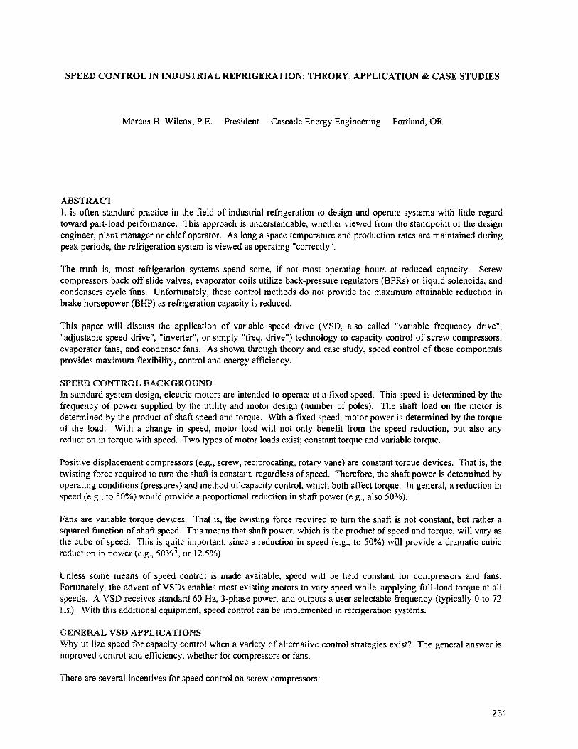
SCREW COMPRESSOR OPERATIONNearly all rotary screw compressors utilize a slide valve for unloading. The slide valve moves along the length ofthe rotors, reducing the compression length within the rotors. An internal view of a screw compressor is shown inFigure 1.
Figure 1: Compressor Internal View
DISCHA.RGEPLATE
SPINDLE
Compressor-Exploded ViewROTOR CASING
/
tfEMAl.E ROTOR
HYDRAULICUNLOADERCYLINDER
, ~j\
UNl.OADERPISTON
Although this method of control is infinitely adjustable and provides reasonable suction pressure control, there canbe a substantial power penalty associated with slide valve control. As the compressor unloads, there is not aproportional reduction in power. A typical screw compressor part-load curve is shown in Figure 2.
262
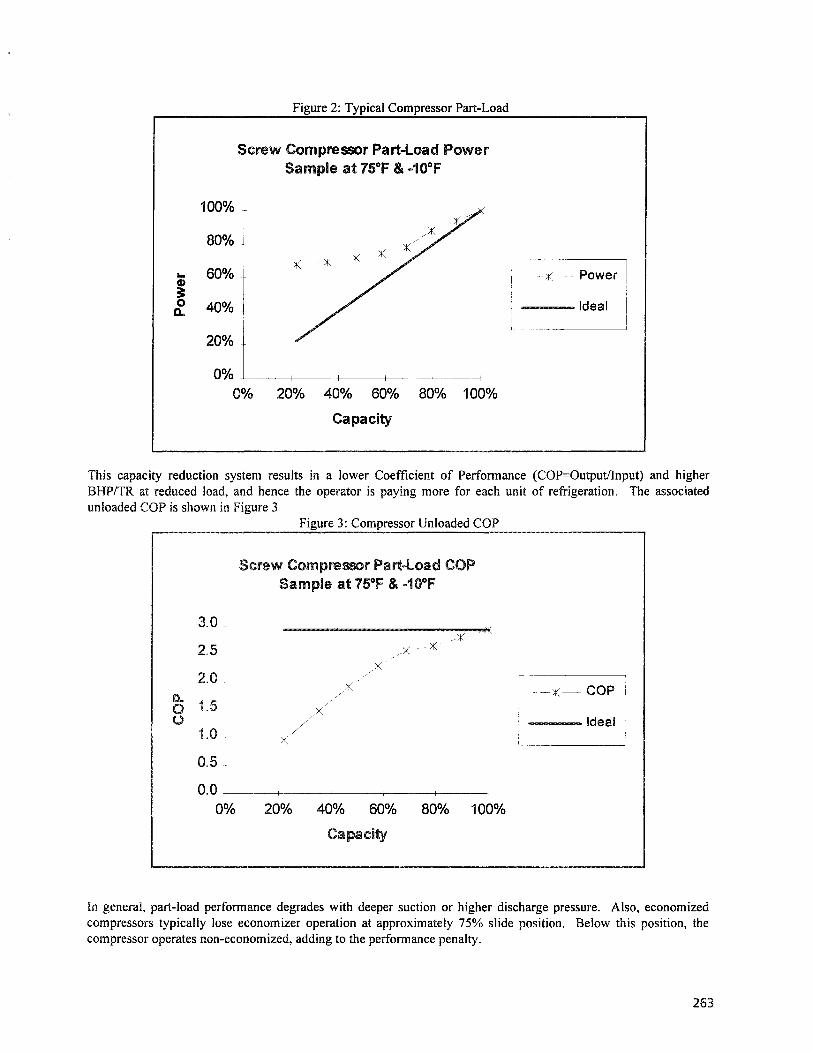
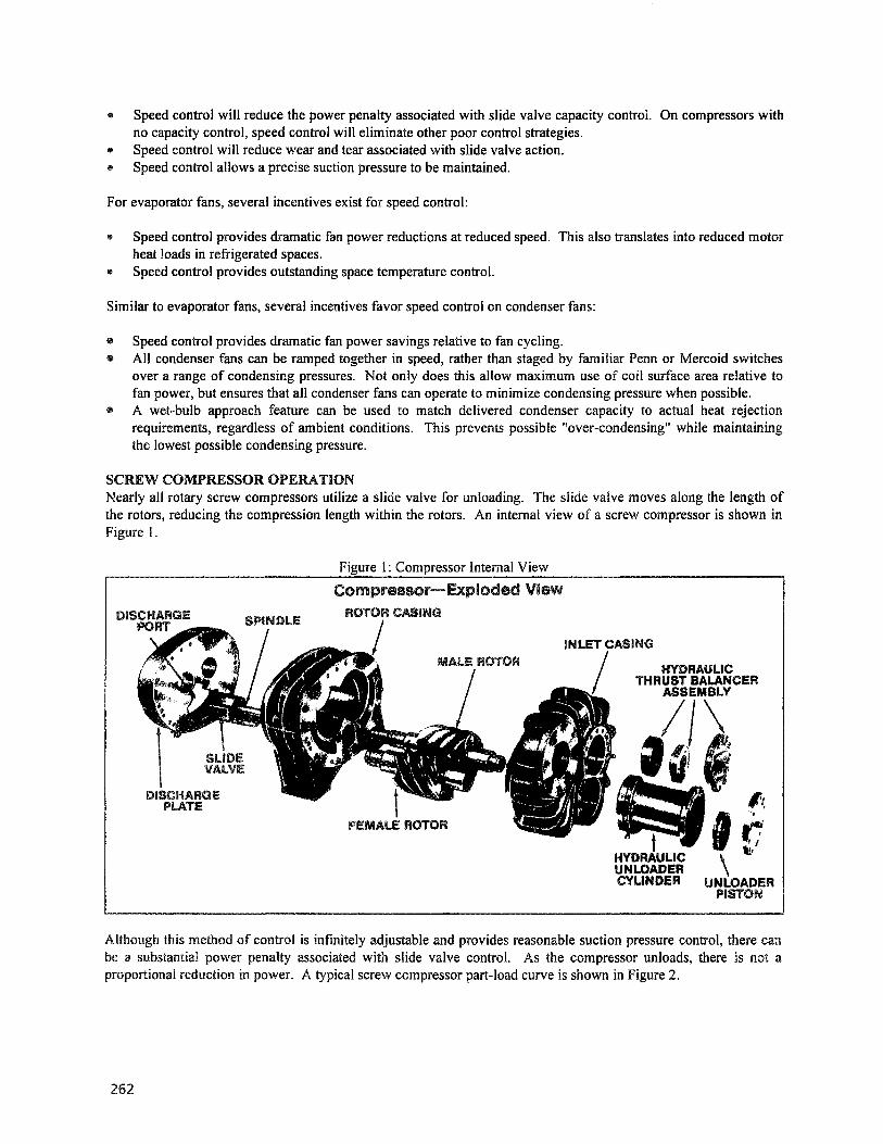
Figure 2: Typical Compressor Part-Load
Screw Compressor Part-Load PowerSample at15°F & ..10°F
100%
800/0
600/0
400/0
200/0
0% +----f-----+----j-----+-----1
0% 200/0 40% 60% 800/0 100%
Capacity
---Ideal
This capacity reduction system results in a lower Coefficient of Performance (COP=Output/lnput) and higherBHP/TR at reduced load, and hence the operator is paying more for each unit of refrigeration. The associatedunloaded COP is shown in Figure 3
Figure 3: Compressor Unloaded COP
Screw Compressor PartwLoad COPSample at 75°F & mo10°F
3.0
2.5
2.0~
1.500
1.0
0.5
0.0Q0A> 20%
COP
---Ideal
Capacity
In general, part-load performance degrades with deeper suction or higher discharge pressure. Also, economizedcompressors typically lose economizer operation at approximately 75% slide position. Below this position, thecompressor operates non-economized, adding to the perfonnance penalty.
263
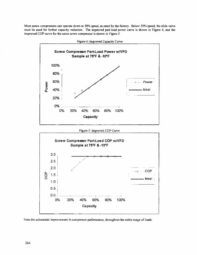
Most screw compressors can operate down to 50% speed, as rated by the factory. Below 50% speed, the slide valvemust be used for further capacity reduction. The improved part-load power curve is shown in Figure 4, and theimproved COP curve for the same screw compressor is shown in Figure 5.
Figure 4: Improved Capacity Curve
Screw Compressor Part-Load Power wNFDSample at 75°F & ...10°F
Power
---Ideal
20°A> 40% 60% BO°A> 100°A>
Capacity
100%
80%
IL- 60%;0 40°A>Q.
20%
0%0%
Figure 5: Improved COP Curve
Screw Compressor Part-Load COP wNFDSample at 75°f & m100f
COP
---Ideal1 --'
800/0 100%20% 40% 60%
Capacity
3.0
2.5
2.0
1.5
1.0
0.5
0.0 -t------+------f----+-----+--------l
0%
Note the substantial improvement in compressor perfonnance, throughout the entire range of loads.
264
SCREW COMPRESSOR VSD APPLICATIONBefore installation of a VSD on a screw compressor, several issues should be researched or examined. Theseinclude:
Compressor Minimum Speed: Check with the factory to verify the authorized minimum speed. Often thiswill be 50% of full speed (typically 1800 of 3600 rpm).Motor Capabilities: Check with the motor manufacturer to ensure that the motor can operate with a constanttorque load at 50% speed.. Motor cooling..is typically the limiting factor. Applications may work with existingopen-drip-proof or totally-enclosed fan-cooled motors.Constant Torque VSD: Ensure that the VSD is a capable of constant torque output. Many VSD vendors havetwo model lines of drives, rated for .either variable (fans) orconstant torque loads(compressors).Trim Compressor: In installations with more than one c0tllpressof, savings are maximized by always usingthe compressor with a VSDto perform all capacitytrhnming. .It will rarely be necessary or economicallyprudent to install more than one compressorVSD.Metbod of Control: Two fac.etsof control are important. First, the control system must ensure that speedcontrol is used exclusively down to 50% speed, with theslide·••·valve completely .open. At 50% speed, thecompressor speed must be maintained and continued capacity reduction performed with the slide valve.Second, a refrigeration system control system must be sophisticated enough to sequence compressors in such away that trimming is always performed with the compressor utilizing VSD control.
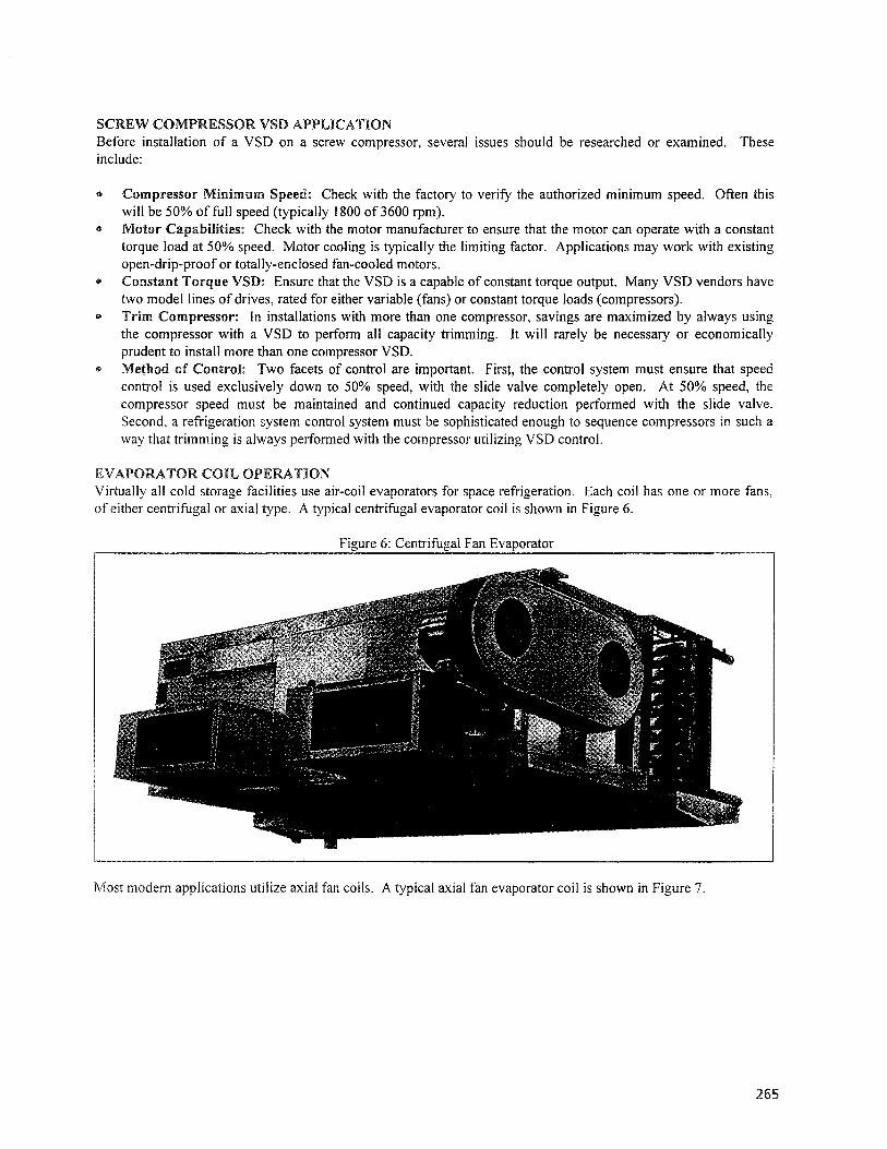
EVAPORATOR COIL OPERATIONV irtually all cold storage facilities use air-coil evaporators for space refrigeration. Each coil has one or more fans,of either centrifugal or axial type. A typical centrifugal evaporator coil is shown in Figure 6.
Figure 6: Centrifugal Fan Evaporator
Most modern applications utilize axial fan coils. A typical axial fan evaporator coil is shown in Figure 7.
265
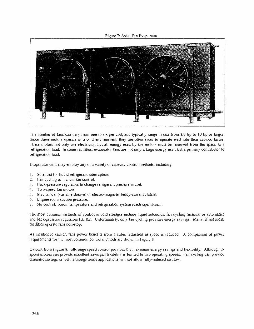
Figure 7: Axial Fan Evaporator
The number of fans can vary from one to six per coil, and typically range in size from 1/3 hp to 10 hp or larger.Since these motors operate in a cold environment, they are often sized to operate well into their service factor.These motors not only use electricity, but all energy used by the motors must be removed from the space as arefrigeration load. In some facilities, evaporator fans are not only a large energy user, but a primary contributor torefrigeration load.
Evaporator coils may employ any of a variety of capacity control methods, including:
I . Solenoid for liquid refrigerant interruption.2. Fan cycling or manual fan control.3. Back-pressure regulators to change refrigerant pressure in coiL4. Two-speed fan motors.5. Mechanical sheave) or electro-magnetic (eddy-current clutch).6. room pressure.7. No control. Room temperature and refrigeration system reach equilibrium.
The most common methods of control in cold storages include liquid solenoids, fan cycling (manual or automatic)and regulators (BPRs). Unfortunately, only fan cycling provides energy savings. Many, if not most,facilities operate fans non-stop.
As mentioned earlier, fans power benefits from a cubic reduction as speed is reduced. A comparison of powerrequirements for the most common control methods are shown in Figure 8.
Evident from 8, full-range speed control provides the maximum energy savings and flexibility. Although 2-motors can provide excellent savings, flexibility is limited to two operating speeds. Fan cycling can provide
dramatic as well, although some applications will not allow fully-reduced air flow.
266
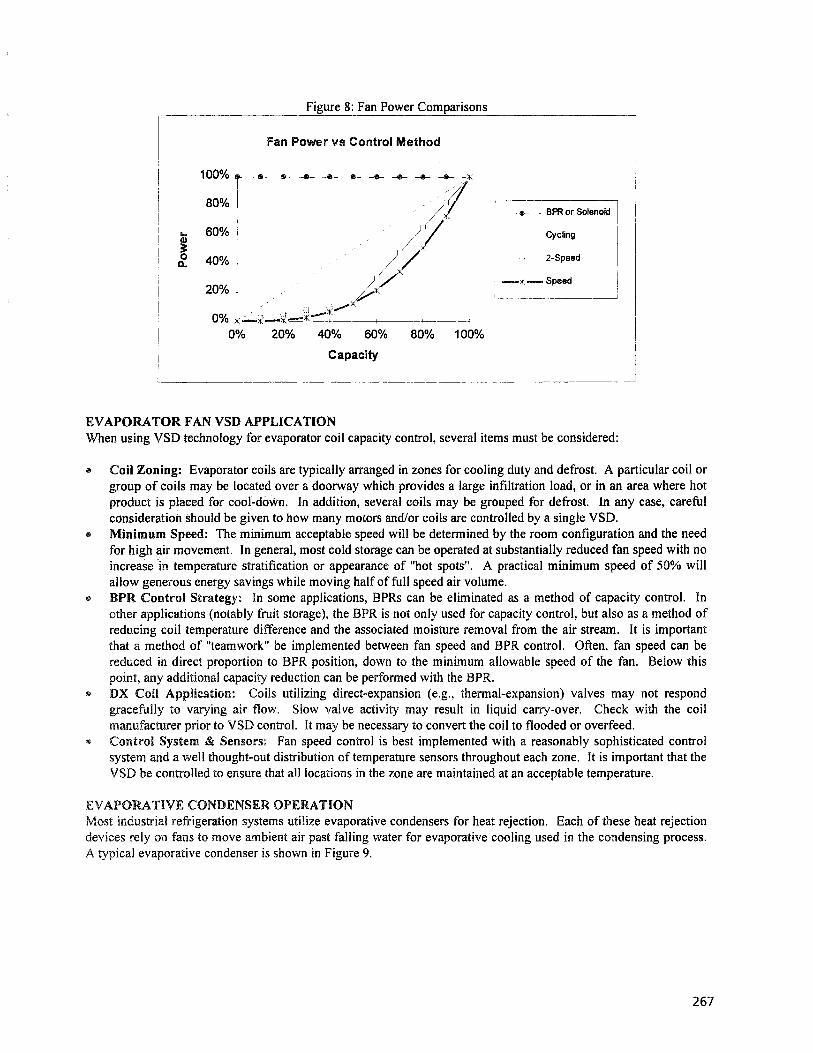
Figure 8: Fan Power Comparisons
Fan Power vs Control Method
e-- BPR or ~OlenOidl
Cycling I
- 2-Speed
--;( ......- Spelld I
EVAP0)UTORFA.N VSD APRLI.CATIONWhen using VSDtechnology for evaporator coil capacity control, several items must be considered:
increase in temperature stratification or appearance of "hotspots". A practical minimum speed of 50% willallow generous energy savings while moving half of full speed air volume.BPR Control Strategy: In some applications, BPRs can be eliminated as a method of capacity control. Inother applications (notably fruit storage), the BPR is not only used for capacity control, but also as a method ofreducing coil temperature difference and the associated moisture removal from the air stream. It is importantthat a method of "teamwork" be implemented between fan speed andBPR control. Often, fan speed can bereduced in direct proportion to BPR position, down to the minimum allowable speed of the fan. Below thispoint, any additional capacity reduction can be performed with the BPR.DX Coil Application: Coils utilizing direct...expansion (e.g., thermal-expansion) valves may not respondgracefully to varying air flow. Slow valve activity may result in liquid carry-over. Check with the coilmanufacturer prior to VSD control. It may be necessary to convert the coil to flooded or overfeed.Control System & Sensors: Fan speed control is best implemented with a reasonably sophisticated controlsystem and a well thought-out distribution of temperature sensors throughout each zone. It is important that theVSD be controlled to ensure that all locations in the zone are maintained at an acceptable temperature.
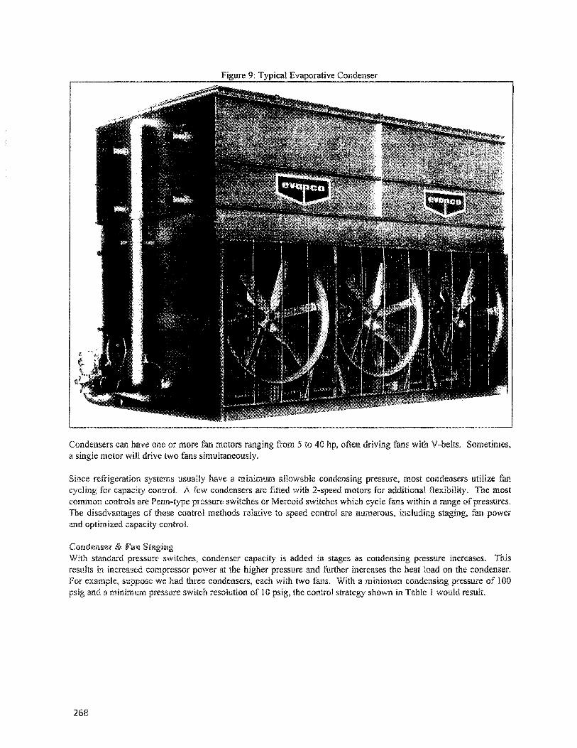
EVAPORATIVE CONDENSER OPERATIONMost industrial refrigeration systems utilize evaporative condensers for heat rejection. Each of these heat rejectiondevices rely on fans to move ambient air past falling water for evaporative cooling used in the condensing process.A typical evaporative condenser is shown in Figure 9.
267
a
Figure 9: Typical Evaporative Condenser
Lo.nac~nserscan have one or more motors a~"'&'R"""".Fl from 5 to 40 hp, oftenmotor win drive two fans surlul1:an€~ou,sly
fans with V-belts.
have a allowable pressure, most condensers utilize fanA few condensers are fitted with motors for additional The most
common controls are pressure switches or Mercoid switches which fans within a rangeThe of these control methods relative to control are numerous, staging, fan powerand controL
Condenser & Fan ~tal2nll2:
With standard pressure condenser is added in as condensing pressure increases. Thisresu.lts in increased compressor power at the pressure and further increases the heat load on the condenser.For suppose we had three each with two fans. With a minimum pressure of 100
and a minimum pressure switch resolution of 10 the control shown in Table 1 would result.
268

Table 1: Condenser Fan Example
Capacity Stage1st Condenser, 1st Fan:1st Condenser, 2nd Fan:2nd Condenser, 1st Fan:2nd Condenser, 2nd Fan:3rd Condenser, 1st Fan:3rd Condenser, 2nd Fan:
CyclesOfr
(psjg)100105110115120125
CyclesOn
(pUg)110115120125130135
In this example of cycling and pressure switch control, the condensing pressure must reach 135 psig before totalcondenser capacity is on-line. This results in excessive condensing pressure, higher compressor power and poor useof available condenser surface area. With speed control, a single target pressure setpoint can be maintained, with allcondenser capacity available ifnecessary.
Fan PowerIn the previous example, condenser fan power varies directly with capacity contribution. No advantage is taken ofthe cubic relationship between fan speed and power. As a follow-up, assume that each of the fans in the previousexample were 10 hp each. A comparison between fan power associated with cycling control and speed control isshown in Table 2 and graphically in Figure 10.
Table 2: Condenser Fan Power ExampleCondensing G/o Cycle VSDCapacity StaKe ~ H£ Hf1st Condenser, Ist Fan: 17% 10 0.31st Condenser, 2nd Fan: 33% 20 2.22nd Condenser, 1st Fan: 50% 30 7.52nd Condenser, 2nd Fan: 67% 40 18.13rd Condenser, 1st Fan: 83% 50 34.33rd Condenser, 2nd Fan: 100% 60 60.0
Figure 10: Condenser Fan Power
Condenser Fan Power Example
60
50
a... 40;0
30Q.,(\)
f!0 20:x:
10
0
0%
II
II
I
,,~
""""""
20°J'o 40°J'o 60% 80% 100%
Total Condenser Capacity
--11--- Cycling
269
It is clear that speed control offers superior power reduction at all levels of condenser capacity. This, coupled withreduced condensing pressure, can offer substantial compressor and condenser fan savings.
Optimized Capacity ControlA strong incentive exists to operate condenser fans to drive down condensing pressure. The savings in compressorpower can be substantial. Unfortunately, pressure switches are simple devices. The condenser fans only know tooperate when the condensing pressure reaches a particular setpoint, regardless of actual heat rejection load. Thisresults in "over-condensing", where less than 100% condenser capacity is desirable, but the simple control systemcannot match capacity to load.
Often, the compressor energy savings is reduced or even offset by the increased condenser fan power required todrive down the condensing pressure. It is important that some type of optimized condenser capacity control be usedto minimize combined compressor/condenser power. VSD control adds the necessary flexibility and fan powersavings to fully optimize condenser/compressor interaction.
CONDENSER FAN VSD APPLICATIONSeveral important VSD application considerations and control features are recommended to ensure maximumenergy efficiency when utilizing VSD technology on condenser or cooling tower fans.
\$ Fan/Condenser VSD Grouping: To ensure full energy savings with reasonable control and maintenanceabilities, it is often best to install one VSD for each condenser. This provides a balance between flexibility andfirst cost.
@ Simultaneous Ramping: It is very important that all condensers be ramped together in speed, not sequentially.This will ensure maximum energy savings and simple control strategies.
\$ Wet Bulb Approach: A wet bulb approach feature should be used to control condensing capacity. That is,condenser fan speed should be varied to maintain a condensing temperature that is held at a user specifiedtemperature difference above the ambient wet bulb. This temperature difference is commonly set between 10°Fand 15°F. The setpoint should allow the condenser to spend most operating time in the range of 50% to 80%speed when above the minimum condensing pressure setpoint.
\$ Control System: A control system will provide the best method of condenser fan VSD control, although somesystems may work satisfactorily with simple PLCs. The system should handle wet bulb approach, simultaneousramping, and a user selected minimum condensing pressure setpoint. It may also be necessary to bumpcondensing pressure up during hot gas defrost.
GENERAL IMPLEMENTATION NOTESSeveral items of interest concerning installation of VSDs in refrigeration are listed below:
1" Harmonics: All VSDs generate harmonics. The quality and installation of the drive detennine the existenceand magnitude of harmonic problems. Buy quality drives and have them installed by someone with experiencein VSD installations. Often, an isolation transformer may be required to prevent undesirable feedback into themain power system.
2$ Line Reactors and Transformers: Most drive manufacturers recommend separate output and inputwiring runs in applications with multiple VSDs. Wiring input and/or output leads from multiple drives in asingle gutter or conduit can result in degraded wave form quality and cross-talk. In addition, for installationswith multiple small motors on a single drive and/or long wiring runs, it may be necessary to install line reactorsclose to the motors to eliminate motor wear or failure associated with excessive voltage and "ringing". Finally,it may also be necessary to install a choke on the output of the VSD to protect the drive from the same voltagefluctuations.
3.. Motor Selection or Review: Most motor manufacturers offer a line of "inverter-duty" motors. Typically,these motors are designed for the high dV/dt and diminished motor cooling experienced with VSD applications.Often, motor manufacturers will suggest premium efficiency motors for inverter duty. In retrofit applications,it may be possible to use existing motors with VSDs, as long as issues of motor insulation and output wave
270
form quality are addressed. For some retrofit projects using existing motors, operating 460 volt motors at 230volts with VSDs and line reactors will provide sufficient "cushion" to prevent motor degradation.
40 VSD/Motor System Design: It is often prudent to budget for a VSD application specialist to assist in overallsystem implementation as well as post-installation measurements of performance. A system-wide analysis priorto installation will ensure that all necessary components have been reviewed for compatibility and satisfactoryoperation.
50 Manual Override: Consider providing for manual override in the case of VSD or control system failure. Thismight include auxiliary starters and pressure switch controls.
60 2-Speed vs VSD: Closely examine the cost of 2-speed motors versus VSDs. When including the 2-speedstarter and considering the decreasing price of VSDs, there is little reason left to install 2-speed motors. Inaddition, 2-speed motors have poor efficiencies, even relative to the 95-98% efficiency of a VSD.
7" Limit of Fan Savings: There is little reason to reduce fan speed below 500/0, since theoretical input power isonly 12.5% at this point.
~t Necessity of Good Controls: Although some VSD installations may be operated with simple controls or aPLC, it really requires a sophisticated (not necessarily complicated or proprietary) control system to ensureproper operation and maximum savings.
9" Compressor Selection vs VSD Control: A VSD may not always be the answer to compressor capacitycontrol. Selecting compressors at proper sizes may allow sequencing for energy savings. Often, areciprocating compressor can be used for trim, since they have reasonable part-load power curves. Considercost, savings, maintenance, and space prior to choosing a form of capacity control.
lOs Don't Operate Above 60 Hz: Although some compressors can operate as high as 4500 rpm (rather than thestandard 3600 rpm), avoid the temptation to wring additional performance from the VSD/motor/compressorcombination. Also, operating a fan above 60 Hz can bum out a VSD and/or motor due to excessive load.Operating a fan at 65 Hz results in a load increase of nearly 300/0 over 60 Hz operation.
1j D Select Right Type and Size of VSD: It can't be emphasized enough that the right VSD must be chosen tomatch the load (constant or variable torque) and the motor. Some applications (e.g., evaporator fans) arenotorious for operating into the motor service factor. Ensure that the electrical contractor or other involvedparties are aware of all necessary component operating loads prior to selecting the type and size of a drive.
12" Check With Manufacturers: Contact the manufacturer of the compressor, VSD and motor to verify correctoperation at reduced speed. Set a minimum operational speed for each component of the project.
CASE STUDIESSeveral case studies ofVSD technology applied to industrial refrigeration are presented below:
A 250,000 sq.ft. - 10°F freezer and 78,000 sq.ft. repack area at 55°F. Refrigeration systems consists of the followingcomponents:
(3) 500 hp screw compressors at -28°F suction.(]) 125 hp screw compressor at 30°F suction.(2) Evaporative condensers with 80 hp of fans.(22) Evaporator coils with 269 hp of fans.
VSDs were installed on the following components:
271

(I) 500 hp VSD on a screw compressor.(2) 40 hp VSDs on the evaporative condensers.(16) VSDs totaling 375 hp on evaporator and O.A. fans.
Sysco - Wilsonville, Oregon
A 80,000 sq.ft.cold storage facility used for food products. Refrigeration system consists of the followingcomponents:
( I) 150 hp screw compressor(2) 125 hp screw compressors( 1) 100 hp screw compressor( I) Evap. condenser with 30 hp of 2-speed fans.(26) Evaporator coils with 81 hp of fans.
VSDs were installed on the following components:
(7) VSDs totaling 36 hp on evaporator fans.
Naumes #6, 7 & 8 "" Medford, Oregon
A 45,000 sq.ft. storage for bulk, boxed and controlled atmosphere fruit. Refrigeration system consists of thefollowing components:
(2) 250 hp screw compressors(I) 150 hp screw compressor(2) Evaporative condensers with 33 hp of fans.(36) Evaporator coils with 208 hp of fans.
VSDs were installed on the following components:
(1) 150 hp VSD on the 150 hp compressor.(5) VSDs totaling 180 hp on evaporator fans.
Naumes #1, 3 & 9 - Medford, Oregon
A 38,000 storage for bulk, boxed and controlled atmosphere fruit. Refrigeration system consists of thefoHowing components:
( I) 300 hp screw compressor( 1) 150 hp screw compressor(1) 75 hp screw compressor(2) Evaporative condensers with 50 hp of fans.(28) Evaporator coils with 104 hp of fans.
VSDs were installed on the following components:
(2) VSDs totaling 50 hp on condenser fans.(7) VSDs totaling 120 hp on evaporator fans.
UuckJwaJII.... t-J~oolev Fruit Co.., ... Oden, Oregon
272
A 156,000 sq.ft. storage for bulk, boxed and controlled atmosphere fruit. Refrigeration system consists of thefollowing components:
(3) Screw compressors totaling 700 hp.(5) Reciprocating compressors totaling 305 hp.(6) Evaporative condensers with 77.5 hp of fans.(110) Evaporator coils with 224 hp of fans.
VSDs were installed on the following components:
(1) 150 hp screw compressor(28) VSDs totaling 250 hp on all evaporator coils.(6) VSDs totaling 80 hp on all condenser fans.
Columbia Coistor, - Woodland, Washington
A 105,000 sq.ft. storage and blast facility held at _5°P. Refrigeration system consists of the following components:
(2) 350 hp screw compressors.(1) 400 hp screw compressor.(1) 30 hp & (1) 60 hp reciprocating compressor.( 1) Evaporative condenser with 60 hp of fans.(12) Evaporator coils with 126 hp of fans.
VSDs were installed on the following components:
(1) 60 hp VSD on evaporative condenser.2-speed fans on all evaporator coils.
Umpqua Dairy.". Roseburg, OR
A dairy producing a variety of products, including milk, ice cream, cottage cheese, cream, sour cream andbuttennilk. Refrigeration system consists of the following:
(2) 150 hp screw compressors.(1) 125 hp screw compressor.(4) 60 hp reciprocating compressors.(1) 40 hp reciprocating compressor.(3) Evaporative condensers with 35 hp of fans.(10) Evaporator coils with 42.5 hp of fans.
VSDs were installed on the following components:
(2) VSDs for all evaporative condenser fans.(10) VSDs for all evaporator coils.
Several other facilities are currently installing VSDs to control equipment capacity.
RESEARCHGraduate student research is currently taking place at Oregon State University. A refrigerant flow meter will beused to accurately model economized screw compressor performance at reduced capacity, both with and withoutspeed control. Additional work will be performed on evaporator and condenser VSD installations.
273