industrial refrigeration control valves -...
TRANSCRIPT
aerospaceclimate controlelectromechanicalfiltrationfluid & gas handlinghydraulicspneumaticsprocess controlsealing & shielding
Industrial Refrigeration Control ValvesCatalog C12
Catalog C12, Industrial Refrigeration Control Valves
Refrigerating Specialties Division
We’ve been the world leader in industrial refrigeration for more than 96 years. Our engineering expertise, customer service and manufacturing excellence combine to create a product breadth that is second to none. Products include solenoid valves, pressure regulators, hand valves, liquid level controls, strainers, probes and more.
Parker Industrial’s Refrigeration Group (Refrigerating Specialties and HERL) is the premier valve and control supplier to the food and beverage industry.
As the world’s population grows, so does the need for large scale, refrigerated food preparation and storage
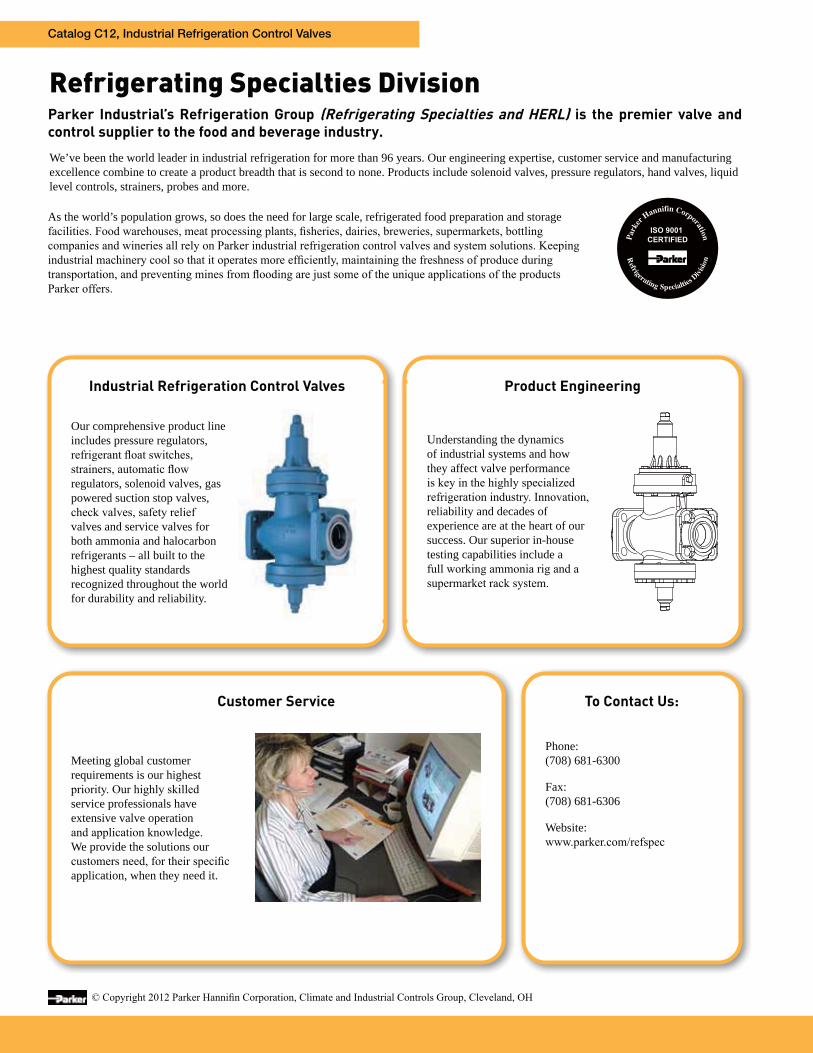
Industrial Refrigeration Control Valves
Customer Service
Our comprehensive product line includes pressure regulators,
regulators, solenoid valves, gas powered suction stop valves,
valves and service valves for both ammonia and halocarbon refrigerants – all built to the highest quality standards recognized throughout the world for durability and reliability.
Understanding the dynamics of industrial systems and how they affect valve performance
reliability and decades of experience are at the heart of our success. Our superior in-house testing capabilities include a
Product Engineering
Meeting global customer requirements is our highest
service professionals have extensive valve operation
We provide the solutions our
application, when they need it.
To Contact Us:
Phone:(708) 681-6300
Fax:(708) 681-6306
Website:
TOC
Catalog C12, Industrial Refrigeration Control Valves
3
Table of ContentsA4 Adaptomode ® Pressure Regulators . . . . . . . 5
ModulesA4A/A4W Suction Capacity TablesA4A/A4W Liquid Capacity TablesA4A/A4W Oil Capacity TablesA4AO Hot Gas Bypass Capacity Tables
810172021
Adaptor Rings . . . . . . . . . . . . . . . . . . . . . . . . . . . . . . 71
Appendix A: Schematic Flow Diagrams . . . . . . . . 160
Appendix B: Dimensional Diagrams . . . . . . . . . . 166
Appendix C: Valve Bolt Torque Specifications . . 216
Appendix D: PED Valve Classification . . . . . . . . . 219
Appendix E: Safety Information . . . . . . . . . . . . . . 221
Check ValvesCK-1 General InformationCK-1 Capacity TablesCK-3 General InformationCK4A General InformationCK4A Capacity Tables
6061646566
Coil Information . . . . . . . . . . . . . . . . . . . . . . . . . . . . . 58
Compact Pressure Regulators . . . . . . . . . . . . . . . 22A2 Suction Capacity TablesA2 Liquid Capacity Tables
2430
Constant Pressure Expansion Valve (PDA) . . . . . 159
Defrost Controller . . . . . . . . . . . . . . . . . . . . . . . . . . . 74
Dual Position Control Valves . . . . . . . . . . . . . . . . . . 56S4AD Capacity TablesCK-2D/CK-6D Capacity Tables
3549
Flanges . . . . . . . . . . . . . . . . . . . . . . . . . . . . . . . . . . . . 70
Flange Unions . . . . . . . . . . . . . . . . . . . . . . . . . . . . . . 71
Gas Powered Valves . . . . . . . . . . . . . . . . . . . . . . . . . 47CK-2/CK-5 Suction Capacity TablesS9A/S9W Suction Capacity TablesGravity Flooded Capacity Tables
495255
General Information . . . . . . . . . . . . . . . . . . . . . . . . . 4
Hand Shut-Off Valves (HV) . . . . . . . . . . . . . . . . . . . . 80
Hand Expansion Valves (HEV) . . . . . . . . . . . . . . . . 81Liquid Overfeed Capacity Tables - Globe “T”Liquid Overfeed Capacity Tables - AngleLiquid Overfeed Capacity Tables - Globe “Y”Liquid Make Up Capacity Tables - Globe “T”Liquid Make Up Capacity Tables - AngleLiquid Make Up Capacity Tables - Globe “Y”
8395
107113119125
Hot Gas Defrost Valve Capacity Tables . . . . . . . . . 72
Level Master Control (LMC) . . . . . . . . . . . . . . . . . . 154Design PrecautionsCapacity Tables
155157
Liquid Level ControlsLiquid Level Control Sensor (HBLC)Liquid Level Sight Glass (SG1)Liquid Level Switches (HBSR, HBSO1 & HBC2)Liquid Level Transmitter (HBLT-A1)Oil Level Control Sensor (HBOC)Refrigerant Float Switch (LLSS)Sight Glass (SA K87 & SA K90)
136139135134137138158
Modulating Refrigerant Valve (MVS) . . . . . . . . . . 129Liquid Make Up Capacity Tables (LPR)Liquid Make Up Capacity Tables (HPR)
130132
Rapid Purger . . . . . . . . . . . . . . . . . . . . . . . . . . . . . . . 128
Refrigerant Distributors . . . . . . . . . . . . . . . . . . . . . 147
Replaceable Core Filter Dryer . . . . . . . . . . . . . . . . 152
Safety Relief ValvesH SeriesSR SeriesSRH SeriesSRLQ Series
75777879
Solenoid ValvesS6N, S8F, SV2, S4A, S5A, S7A General InformationCapacity TablesXJH & XOP General Information
3335
151
StrainersRSF & RSW General InformationXD & Y General Information
69153
Thermostatic Expansion Valves (TXV) . . . . . . . . 140Capacity TablesOil Cooling Thermostatic ChargesSelection Procedure
143145146
TOC
Catalog C12, Industrial Refrigeration Control Valves
4
How to Use this Catalog
expansion.
Temperature increase in a valved off piping section completely full of liquid will cause high pressure due to the expanding liquid which can
removed.
removed.
system. This method is preferred since it operates automatically and requires little attention.
ODS connections are not suitable for ammonia service.
SAFETY PRACTICES
General Information
! WARNING: FAILURE OR IMPROPER SELECTION OR IMPROPER USE OF REFRIGERATING SPECIALTIES DIVISION PRODUCTS, ASSEMBLIES OR RELATED ITEMS
(“PRODUCTS”) CAN CAUSE DEATH, PERSONAL INJURY, AND PROPERTY DAMAGE. POSSIBLE CONSEQUENCES OF FAILURE OR IMPROPER SELECTION OR IMPROPER USE OF
THESE PRODUCTS INCLUDE BUT ARE NOT LIMITED TO:
Before selecting or using any of these Products, it is important that you read and follow the instructions below.
TOC
Catalog C12, Industrial Refrigeration Control Valves
5
Re
gu
lato
rs
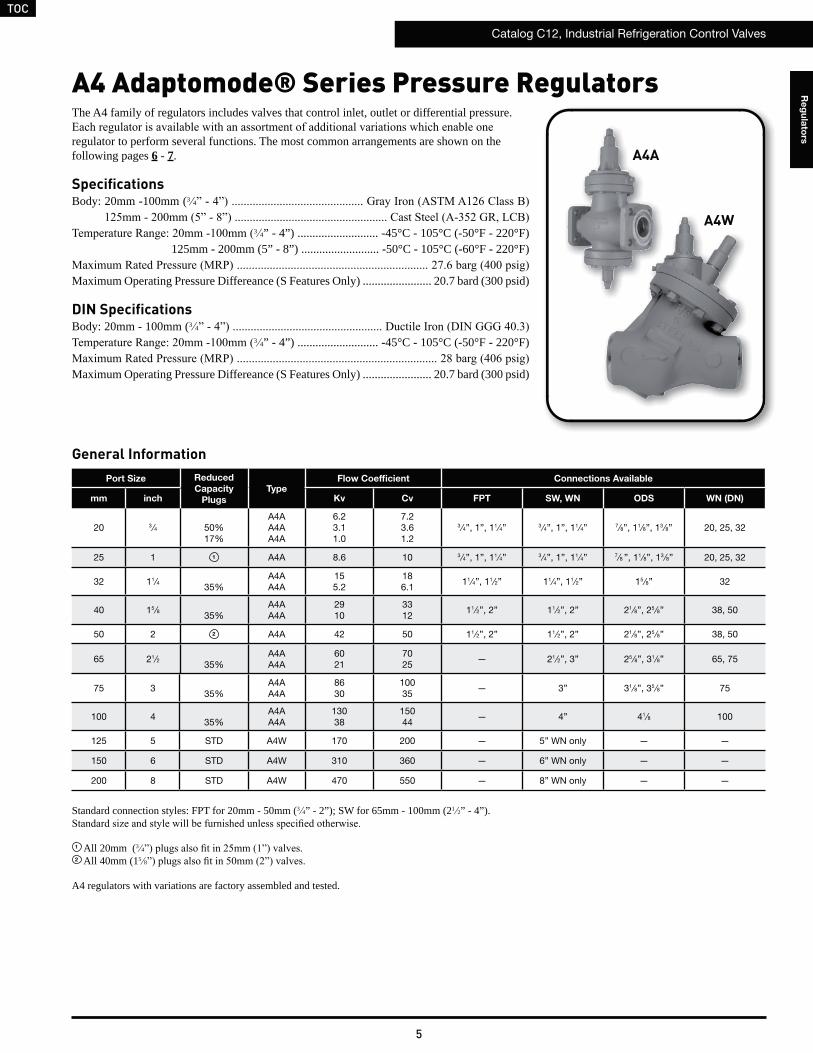
The A4 family of regulators includes valves that control inlet, outlet or differential pressure.
regulator to perform several functions. The most common arrangements are shown on the following pages 6 - 7.
SpecificationsBody: 20mm -100mm (3 4
3 4” - 4”) ........................... -45°C - 105°C (-50°F - 220°F)125mm - 200mm (5” - 8”) .......................... -50°C - 105°C (-60°F - 220°F)
Maximum Operating Pressure Differeance (S Features Only) ....................... 20.7 bard (300 psid)
DIN SpecificationsBody: 20mm - 100mm (3 4
3 4” - 4”) ........................... -45°C - 105°C (-50°F - 220°F)
Maximum Operating Pressure Differeance (S Features Only) ....................... 20.7 bard (300 psid)
A4 Adaptomode® Series Pressure Regulators
Standard connection styles: FPT for 20mm - 50mm (3 4” - 2”); SW for 65mm - 100mm (21 2” - 4”).
1 All 20mm (3 4
2 All 40mm (15 8
A4 regulators with variations are factory assembled and tested.
A4A
A4W
General InformationPort Size Reduced
Capacity
Plugs
TypeFlow Coefficient Connections Available
mm inch Kv Cv FPT SW, WN ODS WN (DN)
20 3 ⁄4 50%17%
A4AA4AA4A
6.23.11.0
7.23.61.2
3 ⁄4”, 1”, 11⁄4” 3 ⁄4”, 1”, 11⁄4” 7⁄8”, 11⁄8”, 13 ⁄8” 20, 25, 32
25 1 1 A4A 8.6 10 3 ⁄4”, 1”, 11⁄4” 3 ⁄4”, 1”, 11⁄4” 7⁄8 ”, 11⁄8”, 13 ⁄8” 20, 25, 32
32 11⁄435%
A4AA4A
155.2
186.1
11⁄4”, 11⁄2” 11⁄4”, 11⁄2” 15 ⁄8” 32
40 15 ⁄835%
A4AA4A
2910
3312
11⁄2”, 2” 11⁄2”, 2” 21⁄8”, 25 ⁄8” 38, 50
50 2 2 A4A 42 50 11⁄2”, 2” 11⁄2”, 2” 21⁄8”, 25 ⁄8” 38, 50
65 21⁄235%
A4AA4A
6021
7025
— 21⁄2”, 3” 25 ⁄8”, 31⁄8” 65, 75
75 335%
A4AA4A
8630
10035
— 3” 31⁄8”, 35 ⁄8” 75
100 435%
A4AA4A
13038
15044
— 4” 41⁄8 100
125 5 STD A4W 170 200 — 5” WN only — —
150 6 STD A4W 310 360 — 6” WN only — —
200 8 STD A4W 470 550 — 8” WN only — —
A4A
A4W
TOC
Catalog C12, Industrial Refrigeration Control Valves
6
Re
gu
lato
rs
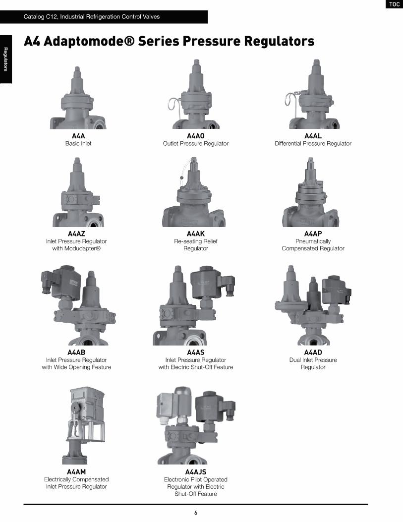
A4AJSElectronic Pilot Operated Regulator with Electric
Shut-Off Feature
A4AMElectrically CompensatedInlet Pressure Regulator
A4 Adaptomode® Series Pressure Regulators
A4ABasic Inlet
A4AOOutlet Pressure Regulator
A4ALDifferential Pressure Regulator
A4AZInlet Pressure Regulator
with Modudapter®
A4AKRe-seating Relief
Regulator
A4APPneumatically
Compensated Regulator
A4ABInlet Pressure Regulator
with Wide Opening Feature
A4ASInlet Pressure Regulator
with Electric Shut-Off Feature
A4ADDual Inlet Pressure
Regulator
TOC
Catalog C12, Industrial Refrigeration Control Valves
7
Re
gu
lato
rs
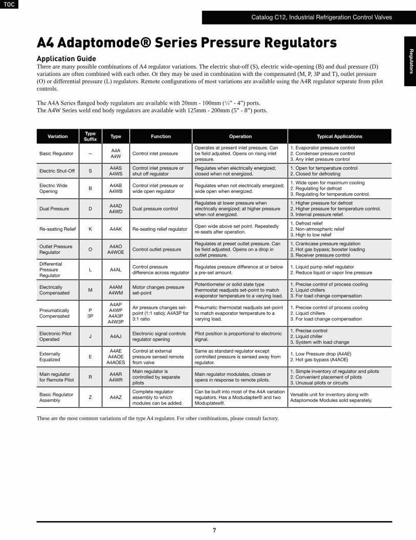
A4 Adaptomode® Series Pressure RegulatorsApplication GuideThere are many possible combinations of A4 regulator variations. The electric shut-off (S), electric wide-opening (B) and dual pressure (D) variations are often combined with each other. Or they may be used in combination with the compensated (M, P, 3P and T), outlet pressure
controls.
3 4” - 4”) ports.The A4W Series weld end body regulators are available with 125mm - 200mm (5” - 8”) ports.
VariationType
SuffixType Function Operation Typical Applications
Basic Regulator —A4A A4W
Control inlet pressureOperates at present inlet pressure. Can be field adjusted. Opens on rising inlet pressure.
1. Evaporator pressure control 2. Condenser pressure control 3. Any inlet pressure control
Electric Shut-Off SA4AS A4WS
Control inlet pressure or shut off regulator
Regulates when electrically energized; closed when not energized.
1. Open for temperature control 2. Closed for defrosting
Electric Wide Opening
BA4AB A4WB
Control inlet pressure or wide open regulator
Regulates when not electrically energized; wide open when energized.
1. Wide open for maximum cooling 2. Regulating for defrost 3. Regulating for temperature control.
Dual Pressure DA4AD A4WD
Dual pressure controlRegulates at lower pressure when electrically energized; at higher pressure when not energized.
1. Higher pressure for defrost 2. Higher pressure for temperature control. 3. Internal pressure relief.
Re-seating Relief K A4AK Re-seating relief regulatorOpen wide above set point. Repeatedly re-seats after operation.
1. Defrost relief 2. Non-atmospheric relief 3. High to low relief
Outlet Pressure Regulator
OA4AO
A4WOEControl outlet pressure
Regulates at preset outlet pressure. Can be field adjusted. Opens on a drop in outlet pressure.
1. Crankcase pressure regulation 2. Hot gas bypass; booster loading 3. Receiver pressure control
Differential Pressure Regulator
L A4ALControl pressure difference across regulator
Regulates pressure difference at or below a pre-set amount.
1. Liquid pump relief regulator 2. Reduce liquid or vapor line pressure
Electrically Compensated
MA4AM A4WM
Motor changes pressure set-point
Potentiometer or solid state type thermostat readjusts set-point to match evaporator temperature to a varying load.
1. Precise control of process cooling 2. Liquid chillers 3. For load change compensation
Pneumatically Compensated
P3P
A4AP A4WP A4A3P A4W3P
Air pressure changes set-point (1:1 ratio); A4A3P for 3:1 ratio
Pneumatic thermostat readjusts set-point to match evaporator temperature to a varying load.
1. Precise control of process cooling 2. Liquid chillers 3. For load change compensation
Electronic Pilot Operated
J A4AJElectronic signal controls regulator opening
Pilot position is proportional to electronic signal.
1. Precise control 2. Liquid chiller 3. System with load change
Externally Equalized
EA4AE
A4AOEA4AOES
Control at external pressure sensed remote from valve
Same as standard regulator except controlled pressure is sensed away from regulator.
1. Low Pressure drop (A4AE) 2. Hot gas bypass (A4AOE)
Main regulator for Remote Pilot
RA4AR A4WR
Main regulator is controlled by separate pilots
Main regulator modulates, closes or opens in response to remote pilots.
1. Simple inventory of regulator and pilots 2. Convenient placement of pilots 3. Unusual pilots or circuits
Basic Regulator Assembly
Z A4AZComplete regulator assembly to which modules can be added.
Can be built into most of the A4A variation regulators. Has a Modudapter® and two Moduplates®.
Versatile unit for inventory along with Adaptomode Modules sold separately.
These are the most common variations of the type A4 regulator. For other combinations, please consult factory.
TOC
Catalog C12, Industrial Refrigeration Control Valves
8
Re
gu
lato
rs
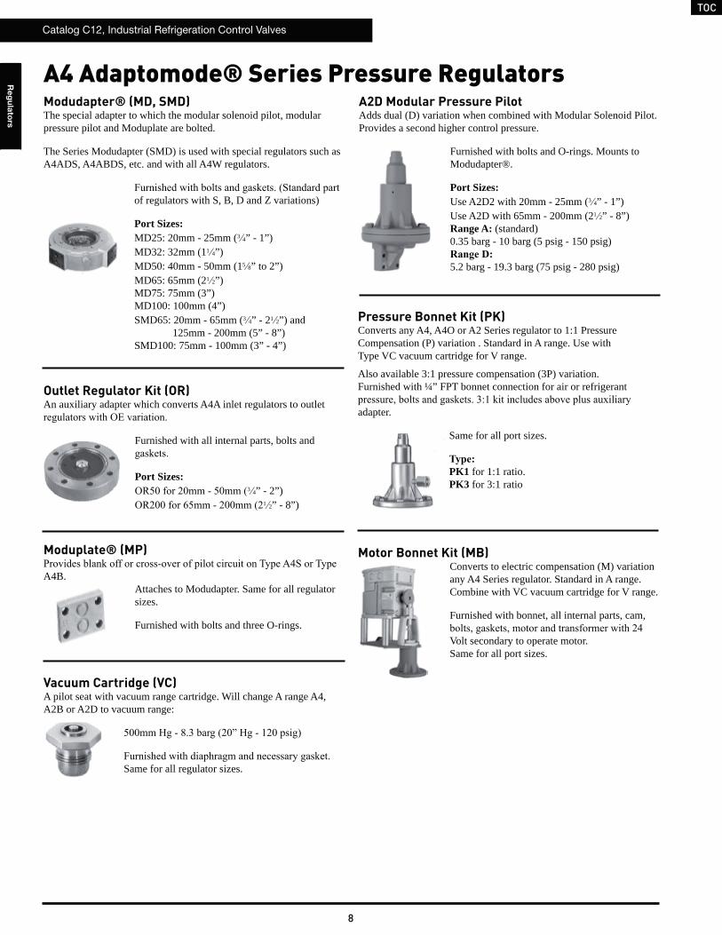
A4 Adaptomode® Series Pressure RegulatorsA2D Modular Pressure PilotAdds dual (D) variation when combined with Modular Solenoid Pilot. Provides a second higher control pressure.
Furnished with bolts and O-rings. Mounts to Modudapter®.
Port Sizes: Use A2D2 with 20mm - 25mm (3 4” - 1”)Use A2D with 65mm - 200mm (21 2” - 8”)Range A: (standard) 0.35 barg - 10 barg (5 psig - 150 psig)
5.2 barg - 19.3 barg (75 psig - 280 psig)
Outlet Regulator Kit (OR)An auxiliary adapter which converts A4A inlet regulators to outlet
Furnished with all internal parts, bolts and
Port Sizes:3 4” - 2”)
1 2” - 8”)
Motor Bonnet Kit (MB)Converts to electric compensation (M) variation any A4 Series regulator. Standard in A range. Combine with VC vacuum cartridge for V range.
Furnished with bonnet, all internal parts, cam,
Volt secondary to operate motor. Same for all port sizes.
Moduplate® (MP)
A4B.Attaches to Modudapter. Same for all regulator sizes.
Furnished with bolts and three O-rings.
Pressure Bonnet Kit (PK)Converts any A4, A4O or A2 Series regulator to 1:1 Pressure Compensation (P) variation . Standard in A range. Use withType VC vacuum cartridge for V range.
Also available 3:1 pressure compensation (3P) variation.Furnished with ¼” FPT bonnet connection for air or refrigerant
adapter.
Same for all port sizes.
PK1 for 1:1 ratio.PK3 for 3:1 ratio
Modudapter® (MD, SMD)The special adapter to which the modular solenoid pilot, modular pressure pilot and Moduplate are bolted.
The Series Modudapter (SMD) is used with special regulators such as A4ADS, A4ABDS, etc. and with all A4W regulators.
of regulators with S, B, D and Z variations)
Port Sizes:MD25: 20mm - 25mm (3 4” - 1”)MD32: 32mm (11 4”)MD50: 40mm - 50mm (15 8” to 2”)MD65: 65mm (21 2”)MD75: 75mm (3”)MD100: 100mm (4”)SMD65: 20mm - 65mm (3 4” - 21 2”) and
125mm - 200mm (5” - 8”)SMD100: 75mm - 100mm (3” - 4”)
Vacuum Cartridge (VC)A pilot seat with vacuum range cartridge. Will change A range A4, A2B or A2D to vacuum range:
Same for all regulator sizes.
TOC
Catalog C12, Industrial Refrigeration Control Valves
9
Re
gu
lato
rs
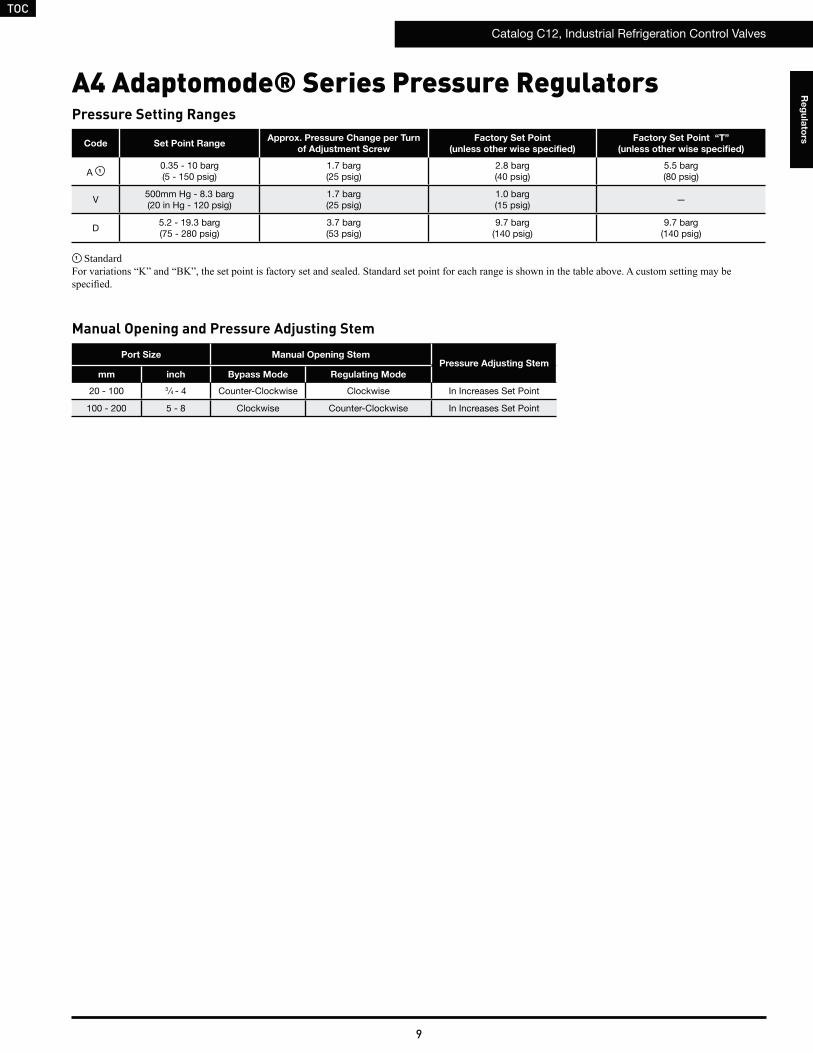
A4 Adaptomode® Series Pressure RegulatorsPressure Setting Ranges
Code Set Point RangeApprox. Pressure Change per Turn
of Adjustment Screw
Factory Set Point
(unless other wise specified)
Factory Set Point “T”
(unless other wise specified)
A 10.35 - 10 barg(5 - 150 psig)
1.7 barg(25 psig)
2.8 barg (40 psig)
5.5 barg(80 psig)
V500mm Hg - 8.3 barg(20 in Hg - 120 psig)
1.7 barg(25 psig)
1.0 barg(15 psig)
—
D5.2 - 19.3 barg(75 - 280 psig)
3.7 barg(53 psig)
9.7 barg(140 psig)
9.7 barg(140 psig)
1 Standard
Port Size Manual Opening StemPressure Adjusting Stem
mm inch Bypass Mode Regulating Mode
20 - 100 3 ⁄4 - 4 Counter-Clockwise Clockwise In Increases Set Point
100 - 200 5 - 8 Clockwise Counter-Clockwise In Increases Set Point
Manual Opening and Pressure Adjusting Stem
TOC
Catalog C12, Industrial Refrigeration Control Valves
10
Re
gu
lato
rs
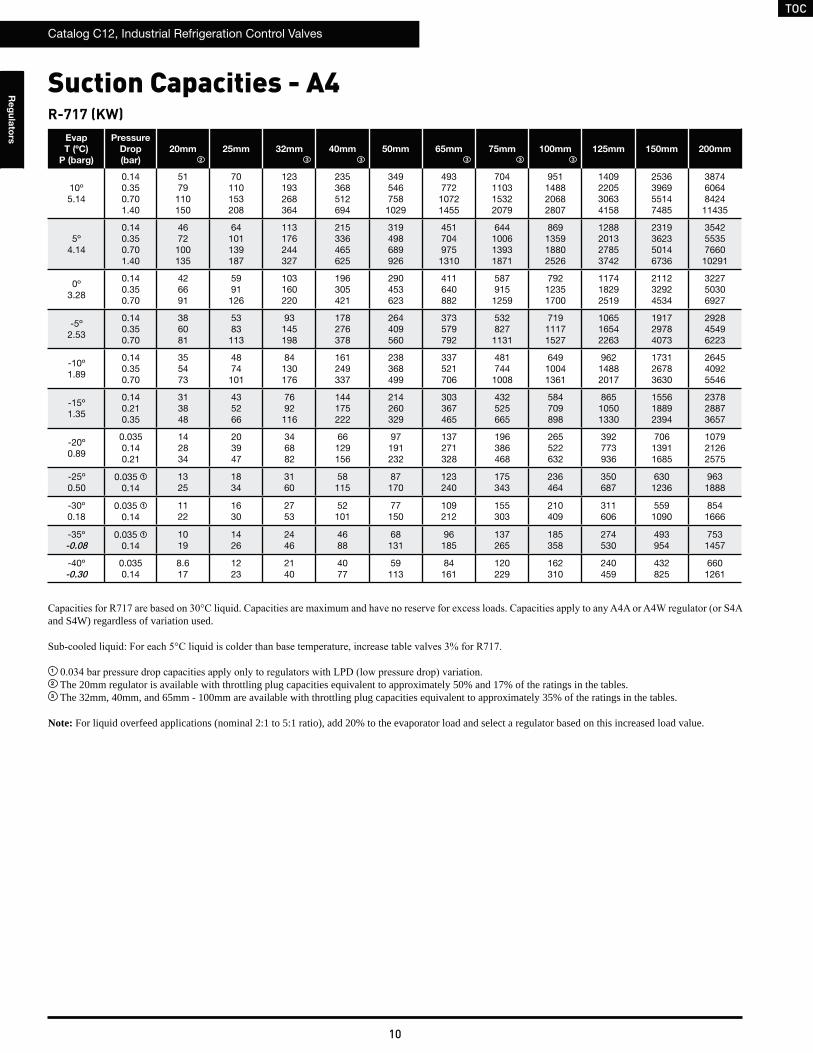
R-717 (KW)Evap
T (ºC)
P (barg)
Pressure
Drop
(bar)
20mm 25mm 32mm 40mm 50mm 65mm 75mm 100mm 125mm 150mm 200mm
10º5.14
0.140.350.701.40
5179110150
70110153208
123193268364
235368512694
349546758
1029
493772
10721455
704110315322079
951148820682807
1409220530634158
2536396955147485
38746064842411435
5º4.14
0.140.350.701.40
4672100135
64101139187
113176244327
215336465625
319498689926
451704975
1310
644100613931871
869135918802526
1288201327853742
2319362350146736
35425535766010291
0º3.28
0.140.350.70
426691
5991126
103160220
196305421
290453623
411640882
587915
1259
79212351700
117418292519
211232924534
322750306927
-5º2.53
0.140.350.70
386081
5383113
93145198
178276378
264409560
373579792
532827
1131
71911171527
106516542263
191729784073
292845496223
-10º1.89
0.140.350.70
355473
4874101
84130176
161249337
238368499
337521706
481744
1008
64910041361
96214882017
173126783630
264540925546
-15º1.35
0.140.21 0.35
313848
435266
7692116
144175222
214260329
303367465
432525665
584709898
86510501330
155618892394
237828873657
-20º0.89
0.0350.140.21
142834
203947
346882
66129156
97191232
137271328
196386468
265522632
392773936
70613911685
107921262575
-25º0.50
0.035 1
0.141325
1834
3160
58115
87170
123240
175343
236464
350687
6301236
9631888
-30º0.18
0.035 1
0.141122
1630
2753
52101
77150
109212
155303
210409
311606
5591090
8541666
-35º-0.08
0.035 1
0.141019
1426
2446
4688
68131
96185
137265
185358
274530
493954
7531457
-40º-0.30
0.0350.14
8.617
1223
2140
4077
59113
84161
120229
162310
240459
432825
6601261
and S4W) regardless of variation used.
1
2 The 20mm regulator is available with throttling plug capacities equivalent to approximately 50% and 17% of the ratings in the tables.3 The 32mm, 40mm, and 65mm - 100mm are available with throttling plug capacities equivalent to approximately 35% of the ratings in the tables.
Note: For liquid overfeed applications (nominal 2:1 to 5:1 ratio), add 20% to the evaporator load and select a regulator based on this increased load value.
Suction Capacities - A4
32 3 3 3 3
TOC
Catalog C12, Industrial Refrigeration Control Valves
11
Re
gu
lato
rs
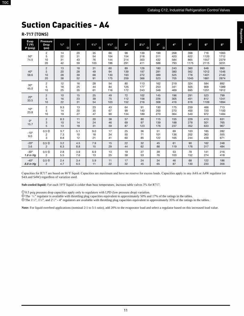
Suction Capacities - A4R-717 (TONS)
Evap
T (ºF)
P (psig)
Pressure
Drop
(psi)
3 ⁄4” 1” 11 ⁄4” 15 ⁄8” 2” 21 ⁄2” 3” 4” 5” 6” 8”
50º74.5
251020
14223142
20314359
355476103
66104144196
98154214291
139218303411
199311432588
268420584793
398622865
1175
716112015572115
1093171223793231
40º58.6
251020
13202838
18283952
31496891
6094
130175
89139193259
126197272366
180281389523
243380525705
360562778
1045
648101214011881
990154621402874
30º45.0
2510
121825
162535
284461
5484
116
80125172
113177243
162253348
219341469
324505695
584909
1251
89213891912
20º33.5
2510
101622
152331
253954
4975
103
72112152
102158216
145226308
196305416
291451616
523812
1109
79912411694
10º23.8
2510
9.31419
132027
233547
436790
6499
134
91140189
130200270
175270364
259400540
466720972
71311001484
0º15.7
235
8.31013
111418
202431
384659
576987
8097
123
115139176
155188237
229278352
413501633
631765967
-10º9.0
0.5 1
23
3.77.38.8
5.11012
9.01821
173441
255060
367185
51101122
69136165
103202244
185363439
282555671
-20º3.6
0.5 1
23.26.3
4.58.8
7.915
1529
2244
3262
4588
61119
90176
162317
248484
-30º1.6 in Hg
0.5 1
22.85.5
3.97.6
6.913
1325
1938
2753
3976
53103
78152
141274
216418
-40º8.8 in Hg
0.5 1
22.44.7
3.46.5
5.911
1122
1732
2445
3465
4687
68130
122233
186356
S4A and S4W) regardless of variation used.
1
2 The 3 4 ” regulator is available with throttling plug capacities equivalent to approximately 50% and 17% of the ratings in the tables.3 The 11 4”, 15 8”, and 21 2” - 4” regulators are available with throttling plug capacities equivalent to approximately 35% of the ratings in the tables.
Note: For liquid overfeed applications (nominal 2:1 to 5:1 ratio), add 20% to the evaporator load and select a regulator based on this increased load value.
32 3 3 3
TOC
Catalog C12, Industrial Refrigeration Control Valves
12
Re
gu
lato
rs
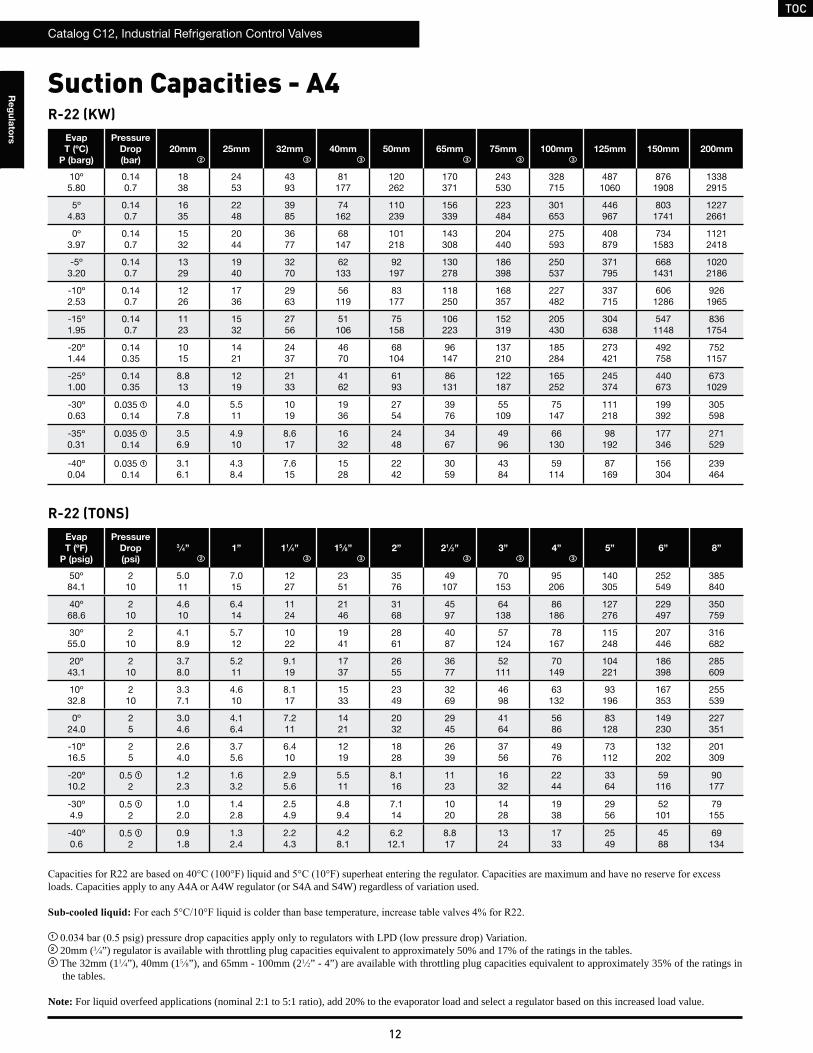
Suction Capacities - A4R-22 (KW)
Evap
T (ºC)
P (barg)
Pressure
Drop
(bar)
20mm 25mm 32mm 40mm 50mm 65mm 75mm 100mm 125mm 150mm 200mm
10º5.80
0.140.7
1838
2453
4393
81177
120262
170371
243530
328715
4871060
8761908
13382915
5º4.83
0.140.7
1635
2248
3985
74162
110239
156339
223484
301653
446967
8031741
12272661
0º3.97
0.140.7
1532
2044
3677
68147
101218
143308
204440
275593
408879
7341583
11212418
-5º3.20
0.140.7
1329
1940
3270
62133
92197
130278
186398
250537
371795
6681431
10202186
-10º2.53
0.140.7
1226
1736
2963
56119
83177
118250
168357
227482
337715
6061286
9261965
-15º1.95
0.140.7
1123
1532
2756
51106
75158
106223
152319
205430
304638
5471148
8361754
-20º1.44
0.140.35
1015
1421
2437
4670
68104
96147
137210
185284
273421
492758
7521157
-25º1.00
0.140.35
8.813
1219
2133
4162
6193
86131
122187
165252
245374
440673
6731029
-30º0.63
0.035 1 0.14
4.07.8
5.511
1019
1936
2754
3976
55109
75147
111218
199392
305598
-35º0.31
0.035 1
0.143.56.9
4.910
8.617
1632
2448
3467
4996
66130
98192
177346
271529
-40º0.04
0.035 1
0.143.16.1
4.38.4
7.615
1528
2242
3059
4384
59114
87169
156304
239464
R-22 (TONS)Evap
T (ºF)
P (psig)
Pressure
Drop
(psi)
3 ⁄4” 1” 11 ⁄4” 15 ⁄8” 2” 21 ⁄2” 3” 4” 5” 6” 8”
50º84.1
210
5.011
7.015
1227
2351
3576
49107
70153
95206
140305
252549
385840
40º68.6
210
4.610
6.414
1124
2146
3168
4597
64138
86186
127276
229497
350759
30º55.0
210
4.18.9
5.712
1022
1941
2861
4087
57124
78167
115248
207446
316682
20º43.1
210
3.78.0
5.211
9.119
1737
2655
3677
52111
70149
104221
186398
285609
10º32.8
210
3.37.1
4.610
8.117
1533
2349
3269
4698
63132
93196
167353
255539
0º24.0
25
3.04.6
4.16.4
7.211
1421
2032
2945
4164
5686
83128
149230
227351
-10º16.5
25
2.64.0
3.75.6
6.410
1219
1828
2639
3756
4976
73112
132202
201309
-20º10.2
0.5 1
21.22.3
1.63.2
2.95.6
5.511
8.116
1123
1632
2244
3364
59116
90177
-30º4.9
0.5 1
21.02.0
1.42.8
2.54.9
4.89.4
7.114
1020
1428
1938
2956
52101
79155
-40º0.6
0.5 1
20.91.8
1.32.4
2.24.3
4.28.1
6.212.1
8.817
1324
1733
2549
4588
69134
loads. Capacities apply to any A4A or A4W regulator (or S4A and S4W) regardless of variation used.
1
2 20mm (3 4”) regulator is available with throttling plug capacities equivalent to approximately 50% and 17% of the ratings in the tables.3 The 32mm (11 4”), 40mm (15 8”), and 65mm - 100mm (21 2” - 4”) are available with throttling plug capacities equivalent to approximately 35% of the ratings in
the tables.
Note: For liquid overfeed applications (nominal 2:1 to 5:1 ratio), add 20% to the evaporator load and select a regulator based on this increased load value.
2
2
3 3 3 3 3
3 3 3 3 3
TOC
Catalog C12, Industrial Refrigeration Control Valves
13
Re
gu
lato
rs
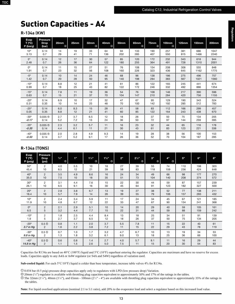
Suction Capacities - A4R-134a (KW)
Evap
T (ºC)
P (barg)
Pressure
Drop
(bar)
20mm 25mm 32mm 40mm 50mm 65mm 75mm 100mm 125mm 150mm 200mm
10º3.13
0.140.7
1429
1941
3371
64136
94202
133285
190407
257550
381815
6861466
10472240
5º2.48
0.140.7
1226
1736
3064
57122
85180
120255
172364
232491
343728
6181310
9442001
0º1.91
0.140.7
1123
1532
2756
51108
76160
108226
154323
208436
308645
5551162
8481775
-5º1.42
0.140.7
1020
1428
2450
4695
68140
96198
138284
186383
275567
4961021
7571560
-10º0.99
0.140.7
8.818
1225
2143
4182
61122
86172
122246
165332
245492
441886
6741354
-15º0.63
0.140.7
7.815
1121
1937
3670
54104
76147
108210
146284
217420
390756
5961155
-20º0.31
0.140.35
6.910
1014
1725
3248
4770
67100
95142
129192
190285
343512
524783
-25º0.05
0.140.35
6.08.8
8.312
1521
2841
4160
5885
83122
112164
166243
299438
457670
-30º-0.17
0.035 1 0.14
2.75.2
3.77.2
6.513
1224
1836
2650
3772
5097
75144
134259
205395
-35º-0.35
0.035 1
0.142.34.4
3.26.1
5.711
1121
1630
2343
3261
4483
65123
116221
178338
-40º-0.50
0.035 1
0.142.03.7
2.85.2
4.99.1
9.317
1426
1936
2852
3870
56104
100187
153285
R-134a (TONS)Evap
T (ºF)
P (psig)
Pressure
Drop
(psi)
3 ⁄4” 1” 11 ⁄4” 15 ⁄8” 2” 21 ⁄2” 3” 4” 5” 6” 8”
50º45.4
210
4.08.5
5.512
1021
1839
2758
3983
55118
74159
110236
198424
303648
40º35.0
210
3.57.5
4.910
8.618
1635
2451
3473
49104
66140
98208
177374
270572
30º26.1
210
3.16.5
4.49.1
7.616
1530
2245
3064
4491
59123
87182
157327
239500
20º18.4
210
2.85.7
3.87.9
6.714
1326
1939
2755
3879
52106
77157
138283
211432
10º11.9
210
2.44.8
3.46.7
5.912
1122
1733
2447
3467
4590
67134
121241
185368
0º6.5
25
2.13.2
2.94.4
5.17.7
1015
1422
2031
2944
4059
5988
105159
161242
-10º1.9
25
1.82.7
2.53.7
4.46.5
8.412
1318
1826
2537
3450
5175
91134
139205
-20º3.7 in Hg
0.5 1
20.81.6
1.12.2
2.03.8
3.77.2
5.511
7.815
1122
1529
2243
4078
61119
-30º9.8 in Hg
0.5 1
20.71.3
1.01.8
1.73.2
3.26.1
4.79.0
6.713
1018
1325
1936
3466
53100
-40º14.8 in Hg
0.5 1
20.61.1
0.81.5
1.42.6
2.75.0
4.07.5
5.711
8.115
1120
1630
2954
4483
loads. Capacities apply to any A4A or A4W regulator (or S4A and S4W) regardless of variation used.
1
2 20mm (3 4”) regulator is available with throttling plug capacities equivalent to approximately 50% and 17% of the ratings in the tables.3 The 32mm (11 4”), 40mm (15 8”), and 65mm - 100mm (21 2” - 4”) are available with throttling plug capacities equivalent to approximately 35% of the ratings in
the tables.
Note: For liquid overfeed applications (nominal 2:1 to 5:1 ratio), add 20% to the evaporator load and select a regulator based on this increased load value.
2
2 3 3 3 3 3
3 3 3 3 3
TOC
Catalog C12, Industrial Refrigeration Control Valves
14
Re
gu
lato
rs
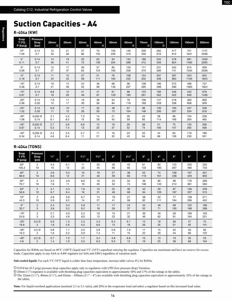
R-404a (KW)Evap
T (ºC)
P (barg)
Pressure
Drop
(bar)
20mm 25mm 32mm 40mm 50mm 65mm 75mm 100mm 125mm 150mm 200mm
10º7.26
0.140.7
1533
2146
3780
70152
103226
146319
209456
282616
417912
7511641
11472508
5º6.11
0.140.7
1430
1941
3372
63138
94204
132288
189412
255556
378824
6811483
10402265
0º5.09
0.140.7
1227
1737
3065
57124
85183
120259
171370
231500
342741
6151334
9392038
-5º4.18
0.140.7
1124
1533
2758
51111
76164
108232
154332
207448
307663
5531194
8451824
-10º3.38
0.140.7
1021
1430
2452
4699
68146
96207
138295
186398
275590
4961063
7571624
-15º2.67
0.140.7
8.819
1226
2146
4187
61129
86183
123261
166352
246522
442940
6761436
-20º2.06
0.140.35
7.912
1117
1930
3656
5484
76118
109169
147228
218338
393608
600928
-25º1.52
0.140.35
6.911
1015
1726
3250
4873
67104
96148
130200
193297
347534
530816
-30º1.06
0.035 1 0.14
3.16.1
4.38.5
7.515
1428
2142
3059
4385
58114
86169
154304
236465
-35º0.67
0.035 1
0.142.75.3
3.87.4
6.613
1325
1937
2652
3874
51100
75147
135265
206406
-40º0.34
0.035 1
0.142.44.6
3.36.4
5.711
1121
1632
2345
3364
4486
65128
118230
180351
R-404a (TONS)Evap
T (ºF)
P (psig)
Pressure
Drop
(psi)
3 ⁄4” 1” 11 ⁄4” 15 ⁄8” 2” 21 ⁄2” 3” 4” 5” 6” 8”
50º105.3
210
4.410
6.113
1123
2045
3066
4393
61133
82180
122267
220480
335733
40º86.9
210
3.98.6
5.512
1021
1840
2759
3883
55119
74161
109238
197429
301655
30º70.7
210
3.57.6
4.911
8.619
1635
2452
3474
49106
66143
98212
176381
269583
20º56.6
210
3.16.7
4.39.4
7.616
1531
2246
3066
4394
59126
87187
156337
239515
10º44.3
210
2.85.9
3.88.2
6.714
1327
1941
2758
3882
52111
77164
138296
211452
0º33.7
25
2.43.8
3.45.2
5.99.2
1118
1726
2437
3452
4671
68105
122189
186288
-10º24.6
25
2.13.3
3.04.6
5.28.0
1015
1523
2132
3046
4062
5991
106164
163251
-20º16.8
0.5 1
20.91.8
1.32.6
2.34.5
4.38.6
6.413
9.118
1326
1835
2651
4792
72141
-30º10.3
0.5 1
20.81.6
1.12.2
2.03.9
3.87.4
5.611
7.915
1122
1530
2244
4080
62122
-40º4.9
0.5 1
20.71.4
1.01.9
1.73.3
3.26.3
4.89.3
6.813
1019
1325
1938
3568
53104
loads. Capacities apply to any A4A or A4W regulator (or S4A and S4W) regardless of variation used.
1
2 20mm (3 4”) regulator is available with throttling plug capacities equivalent to approximately 50% and 17% of the ratings in the tables.3 The 32mm (11 4”), 40mm (15 8”), and 65mm - 100mm (21 2” - 4”) are available with throttling plug capacities equivalent to approximately 35% of the ratings in
the tables.
Note: For liquid overfeed applications (nominal 2:1 to 5:1 ratio), add 20% to the evaporator load and select a regulator based on this increased load value.
Suction Capacities - A4
2
2 3 3 3 3 3
3 3 3 3 3
TOC
Catalog C12, Industrial Refrigeration Control Valves
15
Re
gu
lato
rs
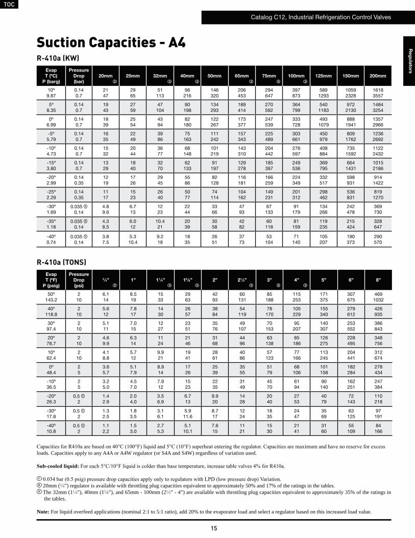
R-410a (KW)Evap
T (ºC)
P (barg)
Pressure
Drop
(bar)
20mm 25mm 32mm 40mm 50mm 65mm 75mm 100mm 125mm 150mm 200mm
10º9.87
0.140.7
2147
2965
51113
98216
146320
206453
294647
397873
5891293
10592328
16183557
5º8.35
0.140.7
1943
2759
47104
90198
134293
189414
270592
364799
5401183
9722130
14843254
0º6.99
0.140.7
1839
2554
4394
82180
122267
173377
247539
333728
4931079
8881941
13572966
-5º5.79
0.140.7
1635
2249
3986
75163
111242
157343
225489
303661
450979
8091762
12362692
-10º4.73
0.140.7
1532
2044
3677
68148
101219
143310
204442
276597
408884
7351592
11222432
-15º3.80
0.140.7
1329
1840
3270
62133
91197
129278
185397
249536
369795
6641431
10152186
-20º2.99
0.140.35
1219
1726
2945
5586
82128
116181
166259
224349
332517
598931
9141422
-25º2.29
0.140.35
1117
1523
2640
5077
74114
104162
149231
201312
298462
536831
8191270
-30º1.69
0.035 1 0.14
4.89.6
6.713
1223
2244
3366
4793
67133
91179
134266
242478
369730
-35º1.18
0.035 1
0.144.38.5
6.012
10.421
2039
3058
4282
60118
81159
119235
215424
328647
-40º0.74
0.035 1
0.143.87.5
5.310.4
9.218
1835
2651
3773
53104
71140
105207
190373
290570
R-410a (TONS)Evap
T (ºF)
P (psig)
Pressure
Drop
(psi)
3 ⁄4” 1” 11 ⁄4” 15 ⁄8” 2” 21 ⁄2” 3” 4” 5” 6” 8”
50º143.2
210
6.114
8.519
1533
2963
4293
60131
85188
115253
171375
307675
4691032
40º118.8
210
5.612
7.817
1430
2657
3884
54119
78170
105229
155340
279612
426935
30º97.4
210
5.111
7.015
1227
2351
3576
49107
70153
95207
140307
253552
386843
20º78.7
210
4.69.9
6.314
1124
2146
3168
4496
63138
85186
126275
228495
348756
10º62.4
210
4.18.8
5.712
9.921
1941
2861
4086
57123
77166
113245
204441
312674
0º48.4
25
3.65.7
5.17.9
8.914
1726
2539
3555
5179
68106
101158
182284
278434
-10º36.5
25
3.25.0
4.57.0
7.912
1523
2235
3149
4570
6194
90140
162251
247384
-20º26.3
0.5 1
21.42.9
2.04.0
3.56.9
6.713
9.920
1428
2040
2753
4079
72143
110218
-30º17.8
0.5 1
21.32.5
1.83.5
3.16.1
5.911.6
8.717
1224
1835
2447
3569
63125
97191
-40º10.8
0.5 1
21.12.2
1.53.0
2.75.3
5.110.1
7.615
1121
1530
2141
3160
55109
84166
Suction Capacities - A4
2
2
loads. Capacities apply to any A4A or A4W regulator (or S4A and S4W) regardless of variation used.
1
2 20mm (3 4”) regulator is available with throttling plug capacities equivalent to approximately 50% and 17% of the ratings in the tables.3 The 32mm (11 4”), 40mm (15 8”), and 65mm - 100mm (21 2” - 4”) are available with throttling plug capacities equivalent to approximately 35% of the ratings in
the tables.
Note: For liquid overfeed applications (nominal 2:1 to 5:1 ratio), add 20% to the evaporator load and select a regulator based on this increased load value.
3 3 3 3 3
3 3 3 3 3
TOC
Catalog C12, Industrial Refrigeration Control Valves
16
Re
gu
lato
rs
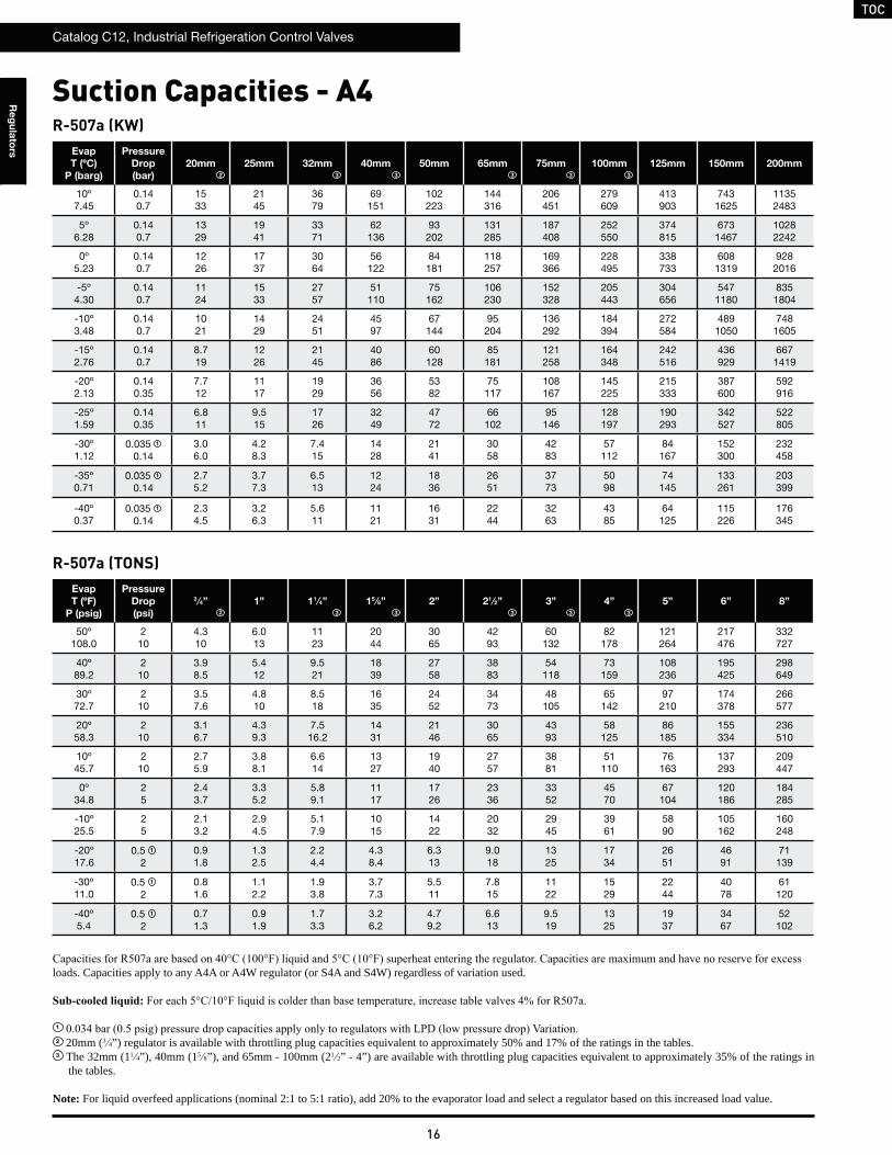
R-507a (KW)Evap
T (ºC)
P (barg)
Pressure
Drop
(bar)
20mm 25mm 32mm 40mm 50mm 65mm 75mm 100mm 125mm 150mm 200mm
10º7.45
0.140.7
1533
2145
3679
69151
102223
144316
206451
279609
413903
7431625
11352483
5º6.28
0.140.7
1329
1941
3371
62136
93202
131285
187408
252550
374815
6731467
10282242
0º5.23
0.140.7
1226
1737
3064
56122
84181
118257
169366
228495
338733
6081319
9282016
-5º4.30
0.140.7
1124
1533
2757
51110
75162
106230
152328
205443
304656
5471180
8351804
-10º3.48
0.140.7
1021
1429
2451
4597
67144
95204
136292
184394
272584
4891050
7481605
-15º2.76
0.140.7
8.719
1226
2145
4086
60128
85181
121258
164348
242516
436929
6671419
-20º2.13
0.140.35
7.712
1117
1929
3656
5382
75117
108167
145225
215333
387600
592916
-25º1.59
0.140.35
6.811
9.515
1726
3249
4772
66102
95146
128197
190293
342527
522805
-30º1.12
0.035 1 0.14
3.06.0
4.28.3
7.415
1428
2141
3058
4283
57112
84167
152300
232458
-35º0.71
0.035 1
0.142.75.2
3.77.3
6.513
1224
1836
2651
3773
5098
74145
133261
203399
-40º0.37
0.035 1
0.142.34.5
3.26.3
5.611
1121
1631
2244
3263
4385
64125
115226
176345
R-507a (TONS)Evap
T (ºF)
P (psig)
Pressure
Drop
(psi)
3 ⁄4” 1” 11 ⁄4” 15 ⁄8” 2” 21 ⁄2” 3” 4” 5” 6” 8”
50º108.0
210
4.310
6.013
1123
2044
3065
4293
60132
82178
121264
217476
332727
40º89.2
210
3.98.5
5.412
9.521
1839
2758
3883
54118
73159
108236
195425
298649
30º72.7
210
3.57.6
4.810
8.518
1635
2452
3473
48105
65142
97210
174378
266577
20º58.3
210
3.16.7
4.39.3
7.516.2
1431
2146
3065
4393
58125
86185
155334
236510
10º45.7
210
2.75.9
3.88.1
6.614
1327
1940
2757
3881
51110
76163
137293
209447
0º34.8
25
2.43.7
3.35.2
5.89.1
1117
1726
2336
3352
4570
67104
120186
184285
-10º25.5
25
2.13.2
2.94.5
5.17.9
1015
1422
2032
2945
3961
5890
105162
160248
-20º17.6
0.5 1
20.91.8
1.32.5
2.24.4
4.38.4
6.313
9.018
1325
1734
2651
4691
71139
-30º11.0
0.5 1
20.81.6
1.12.2
1.93.8
3.77.3
5.511
7.815
1122
1529
2244
4078
61120
-40º5.4
0.5 1
20.71.3
0.91.9
1.73.3
3.26.2
4.79.2
6.613
9.519
1325
1937
3467
52102
loads. Capacities apply to any A4A or A4W regulator (or S4A and S4W) regardless of variation used.
1
2 20mm (3 4”) regulator is available with throttling plug capacities equivalent to approximately 50% and 17% of the ratings in the tables.3 The 32mm (11 4”), 40mm (15 8”), and 65mm - 100mm (21 2” - 4”) are available with throttling plug capacities equivalent to approximately 35% of the ratings in
the tables.
Note: For liquid overfeed applications (nominal 2:1 to 5:1 ratio), add 20% to the evaporator load and select a regulator based on this increased load value.
Suction Capacities - A4
2
2
3 3 3 3 3
3 3 3 3 3
TOC
Catalog C12, Industrial Refrigeration Control Valves
17
Re
gu
lato
rs
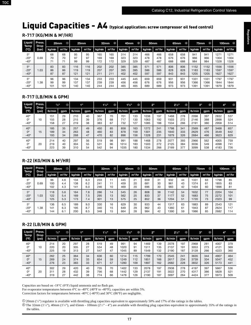
R-717 (KG/MIN & M3/HR)Liquid
Temp
(ºC)
Press.
Drop
(bar)
20mm 25mm 32mm 40mm 50mm 65mm 75mm 100mm
kg/min m3/hr kg/min m3/hr kg/min m3/hr kg/min m3/hr kg/min m3/hr kg/min m3/hr kg/min m3/hr kg/min m3/hr
5º-20º-40º
0.69687071
687071
959799
959799
165169172
165169172
314323329
314323329
466478487
466478487
658676688
658676688
941966984
941966984
127113041328
127113041328
5º-20º-40º
1.03838687
838687
116119121
116119121
202207211
202207211
385395402
385395402
571586597
571586597
806828843
806828843
115211831205
115211831205
155615971627
155615971627
5º-20º-40º
1.389699101
9699101
134137140
134137140
233239244
233239244
445456465
445456465
659676689
659676689
931956973
931956973
133113661391
133113661391
179718441879
179718441879
Liquid Capacities - A4 (typical application: screw compressor oil feed control)
R-717 (LB/MIN & GPM)Liquid
Temp
(ºF)
Press.
Drop
(psi)
3 ⁄4” 1” 11 ⁄4” 15 ⁄8” 2” 21 ⁄2” 3” 4”
lb/min gpm lb/min gpm lb/min gpm lb/min gpm lb/min gpm lb/min gpm lb/min gpm lb/min gpm
40º0º
-40º10
151155158
292827
210215219
403938
367376383
706867
701717732
133130127
103810631085
197192188
146815031534
278272266
209821462191
397388380
283228982958
537524514
40º0º
-40º15
185189193
353434
257263268
494847
450460470
858382
858878896
163159156
127213011328
241235231
179818401879
341333326
256926292684
487476466
346835493623
657642629
40º0º
-40º20
214219223
404039
297304310
565554
519531542
989694
99110141035
188183180
146815031534
278272266
207721252169
393384377
296630363099
562549538
400540984183
759741726
R-22 (KG/MIN & M3/HR)Liquid
Temp
(ºC)
Press.
Drop
(bar)
20mm 25mm 32mm 40mm 50mm 65mm 75mm 100mm
kg/min m3/hr kg/min m3/hr kg/min m3/hr kg/min m3/hr kg/min m3/hr kg/min m3/hr kg/min m3/hr kg/min m3/hr
5º-20º-40º
0.6996100102
4.64.44.3
134138141
6.36.26.0
233241246
111110
445459469
212020
659681696
313030
932961983
444342
133113741404
636160
179818551896
858381
5º-20º-40º
1.03118122125
5.65.45.3
164169173
7.87.57.4
286295301
141313
545562575
262525
808833852
383736
114211771204
545251
163216831720
777573
220422722323
10410199
5º-20º-40º
1.38136141144
6.56.36.1
189195200
9.08.78.5
330340348
161515
629649664
302928
933962984
444342
131713601390
636159
188319431986
898785
254326242682
121117114
R-22 (LB/MIN & GPM)Liquid
Temp
(ºF)
Press.
Drop
(psi)
3 ⁄4” 1” 11 ⁄4” 15 ⁄8” 2” 21 ⁄2” 3” 4”
lb/min gpm lb/min gpm lb/min gpm lb/min gpm lb/min gpm lb/min gpm lb/min gpm lb/min gpm
40º0º
-40º10
214220225
202019
297305313
282727
519534547
494847
99110201045
949189
146915111549
139135132
207821372190
197191187
296830533128
281273266
400741214223
379369360
40º0º
-40º15
262269276
252423
364374383
343333
636654671
605957
121412491280
115112109
179918511897
170166162
254526172682
241234228
363537393832
344334326
490750475173
464452441
40º0º
-40º20
302311319
292827
420432442
403938
735756774
706866
140214421478
133129126
207821372190
197191187
293830223097
278270264
419743174424
397386377
566758285973
536521509
For evaporator temperatures between 4°C to -40°C (40°F to -40°F), capacities are within 5%.Correction factors for temperatures between -40°C (-40°F) and 30°C (86°F) are negligible.
1 20mm (3 4”) regulator is available with throttling plug capacities equivalent to approximately 50% and 17% of the ratings in the tables.2 The 32mm (11 4”), 40mm (15 8”), and 65mm - 100mm (21 2” - 4”) are available with throttling plug capacities equivalent to approximately 35% of the ratings in
the tables.
1
1
1
1
2 2 22 2
2 2 22 2
2 2 22 2
2 2 22 2
TOC
Catalog C12, Industrial Refrigeration Control Valves
18
Re
gu
lato
rs
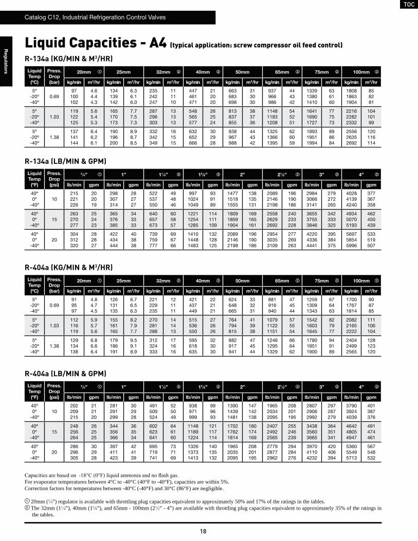
R-134a (KG/MIN & M3/HR)Liquid
Temp
(ºC)
Press.
Drop
(bar)
20mm 25mm 32mm 40mm 50mm 65mm 75mm 100mm
kg/min m3/hr kg/min m3/hr kg/min m3/hr kg/min m3/hr kg/min m3/hr kg/min m3/hr kg/min m3/hr kg/min m3/hr
5º-20º-40º
0.6997100102
4.64.44.3
134139142
6.36.16.0
235242247
111110
447461471
212020
663683698
313030
937966986
444342
133913801410
636160
180818631904
858281
5º-20º-40º
1.03119122125
5.65.45.3
165170173
7.77.57.3
287296303
131313
548565577
262524
813837855
383736
114811831208
545251
164116901727
777573
221622822332
10410199
5º-20º-40º
1.38137141144
6.46.26.1
190196200
8.98.78.5
332342349
161515
632652666
302928
938967988
444342
132513661395
626059
189319511994
898684
255626352692
120116114
R-134a (LB/MIN & GPM)Liquid
Temp
(ºF)
Press.
Drop
(psi)
3 ⁄4” 1” 11 ⁄4” 15 ⁄8” 2” 21 ⁄2” 3” 4”
lb/min gpm lb/min gpm lb/min gpm lb/min gpm lb/min gpm lb/min gpm lb/min gpm lb/min gpm
40º0º
-40º10
215221226
202019
298307314
282727
522537550
494846
99710241049
939189
147715181555
138135131
208921462198
196190186
298430663141
279272265
402841394240
377367358
40º0º
-40º15
263270277
252423
365376385
343333
640657673
605857
122112541285
114111109
180918591904
169165161
255826292692
240233228
365537553846
342333325
493450705193
462450439
40º0º
-40º20
304312320
282827
422434444
403838
739759777
696766
141014481483
132128125
208921462198
196190186
295430353109
277269263
422043364441
395384375
569758545996
533519507
R-404a (KG/MIN & M3/HR)Liquid
Temp
(ºC)
Press.
Drop
(bar)
20mm 25mm 32mm 40mm 50mm 65mm 75mm 100mm
kg/min m3/hr kg/min m3/hr kg/min m3/hr kg/min m3/hr kg/min m3/hr kg/min m3/hr kg/min m3/hr kg/min m3/hr
5º-20º-40º
0.69919597
4.84.74.5
126131135
6.76.56.3
221229235
121111
421437449
222121
624648665
333231
881916940
474544
125913091343
676463
170017671814
908785
5º-20º-40º
1.03112116119
5.95.75.6
155161165
8.27.97.7
270281288
141413
515536550
272626
764794815
413938
107911221151
575554
154216031645
827977
208221652222
111106104
5º-20º-40º
1.38129134138
6.86.66.4
179186191
9.59.18.9
312324333
171616
595618635
323030
882917941
474544
124612951329
666462
178018511900
949189
240424992565
128123120
R-404a (LB/MIN & GPM)Liquid
Temp
(ºF)
Press.
Drop
(psi)
3 ⁄4” 1” 11 ⁄4” 15 ⁄8” 2” 21 ⁄2” 3” 4”
lb/min gpm lb/min gpm lb/min gpm lb/min gpm lb/min gpm lb/min gpm lb/min gpm lb/min gpm
40º0º
-40º10
202209215
212120
281291299
302928
491509524
525049
938971999
999693
139014391481
147142138
196520342095
208201195
280729062992
297287279
379039244039
401387376
40º0º
-40º15
248256264
262525
344356366
363534
602623641
646160
114811891224
121117114
170217621814
180174169
240724922565
255246239
343835603665
364351341
464248054947
491474461
40º0º
-40º20
286296305
302928
397411423
424139
695719741
737169
132613731413
140135132
196520352095
208201195
277928772962
294284276
397041104232
420406394
536055495713
567548532
For evaporator temperatures between 4°C to -40°C (40°F to -40°F), capacities are within 5%.Correction factors for temperatures between -40°C (-40°F) and 30°C (86°F) are negligible.
1 20mm (3 4”) regulator is available with throttling plug capacities equivalent to approximately 50% and 17% of the ratings in the tables.2 The 32mm (11 4”), 40mm (15 8”), and 65mm - 100mm (21 2” - 4”) are available with throttling plug capacities equivalent to approximately 35% of the ratings in
the tables.
1
1
1
1
2 2 22 2
2 2 22 2
2 2 22 2
2 2 22 2
Liquid Capacities - A4 (typical application: screw compressor oil feed control)
TOC
Catalog C12, Industrial Refrigeration Control Valves
19
Re
gu
lato
rs
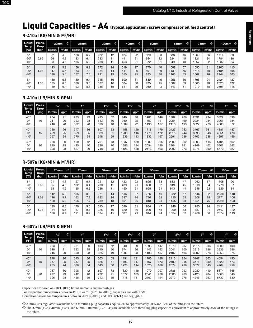
R-410a (KG/MIN & M3/HR)Liquid
Temp
(ºC)
Press.
Drop
(bar)
20mm 25mm 32mm 40mm 50mm 65mm 75mm 100mm
kg/min m3/hr kg/min m3/hr kg/min m3/hr kg/min m3/hr kg/min m3/hr kg/min m3/hr kg/min m3/hr kg/min m3/hr
5º-20º-40º
0.69929698
4.84.64.5
128133136
6.76.46.2
222232238
121111
424441453
222121
629654672
333231
888924949
464543
126913211357
666462
171417841832
898684
5º-20º-40º
1.03113117120
5.95.65.5
156163167
8.27.87.6
272284291
141413
519541555
272625
770801823
403938
108811321163
575553
155516181662
817876
210021852244
110105103
5º-20º-40º
1.38130135139
6.86.56.4
180188193
9.49.08.8
315327336
161615
600624641
313029
889925950
464543
125613071343
666361
179518681919
949088
242425232591
127122118
R-410a (LB/MIN & GPM)Liquid
Temp
(ºF)
Press.
Drop
(psi)
3 ⁄4” 1” 11 ⁄4” 15 ⁄8” 2” 21 ⁄2” 3” 4”
lb/min gpm lb/min gpm lb/min gpm lb/min gpm lb/min gpm lb/min gpm lb/min gpm lb/min gpm
40º0º
-40º10
204211218
212020
283293302
292828
495513529
525048
946980
1009
989592
140114521496
146141137
198220542116
206199193
283129343022
294284276
382239614080
398384372
40º0º
-40º15
250259267
262524
347359370
363534
607629648
636159
115812001236
120116113
171617791832
179172167
242725152591
252244236
346735933702
361348338
468148514997
487470456
40º0º
-40º20
288299308
302928
400415427
424039
701726748
737068
133713861428
139134130
198220542116
206199193
280229042992
292281273
400341494274
416402390
540556015770
562542527
R-507a (KG/MIN & M3/HR)Liquid
Temp
(ºC)
Press.
Drop
(bar)
20mm 25mm 32mm 40mm 50mm 65mm 75mm 100mm
kg/min m3/hr kg/min m3/hr kg/min m3/hr kg/min m3/hr kg/min m3/hr kg/min m3/hr kg/min m3/hr kg/min m3/hr
5º-20º-40º
0.69919598
4.84.64.5
127132135
6.76.46.3
221230236
121111
422439450
222121
625650668
333231
883919943
474544
126213131348
676462
170517731820
908784
5º-20º-40º
1.03112116120
5.95.75.5
155162166
8.27.97.7
271282289
141413
516537551
272626
766796818
403938
108211251155
575553
154616081651
827876
208821712229
110106103
5º-20º-40º
1.38129134138
6.86.66.4
179187191
9.59.18.9
313325334
171615
596620637
313029
884920944
474544
124912991334
666362
178518571906
949188
241125072574
127122119
R-507a (LB/MIN & GPM)Liquid
Temp
(ºF)
Press.
Drop
(psi)
3 ⁄4” 1” 11 ⁄4” 15 ⁄8” 2” 21 ⁄2” 3” 4”
lb/min gpm lb/min gpm lb/min gpm lb/min gpm lb/min gpm lb/min gpm lb/min gpm lb/min gpm
40º0º
-40º10
203210216
212120
281292300
302928
493510525
525049
940974
1003
999693
139314431486
147142137
197020412102
207200194
281529153002
296286278
380039364053
400386375
40º0º
-40º15
248257265
262524
345357368
363534
603625643
636160
115111931228
121117114
170617671820
180173168
241324992574
254245238
344735713677
363350340
465448204964
490473459
40º0º
-40º20
287297306
302928
398412425
424039
697722743
737169
132913771418
140135131
197020412102
207200194
278628862972
293283275
398041234246
419404393
537455665732
565546530
For evaporator temperatures between 4°C to -40°C (40°F to -40°F), capacities are within 5%.Correction factors for temperatures between -40°C (-40°F) and 30°C (86°F) are negligible.
1 20mm (3 4”) regulator is available with throttling plug capacities equivalent to approximately 50% and 17% of the ratings in the tables.2 The 32mm (11 4”), 40mm (15 8”), and 65mm - 100mm (21 2” - 4”) are available with throttling plug capacities equivalent to approximately 35% of the ratings in
the tables.
1
1
1
1
2 2 22 2
2 2 22 2
2 2 22 2
2 2 22 2
Liquid Capacities - A4 (typical application: screw compressor oil feed control)
TOC
Catalog C12, Industrial Refrigeration Control Valves
20
Re
gu
lato
rs
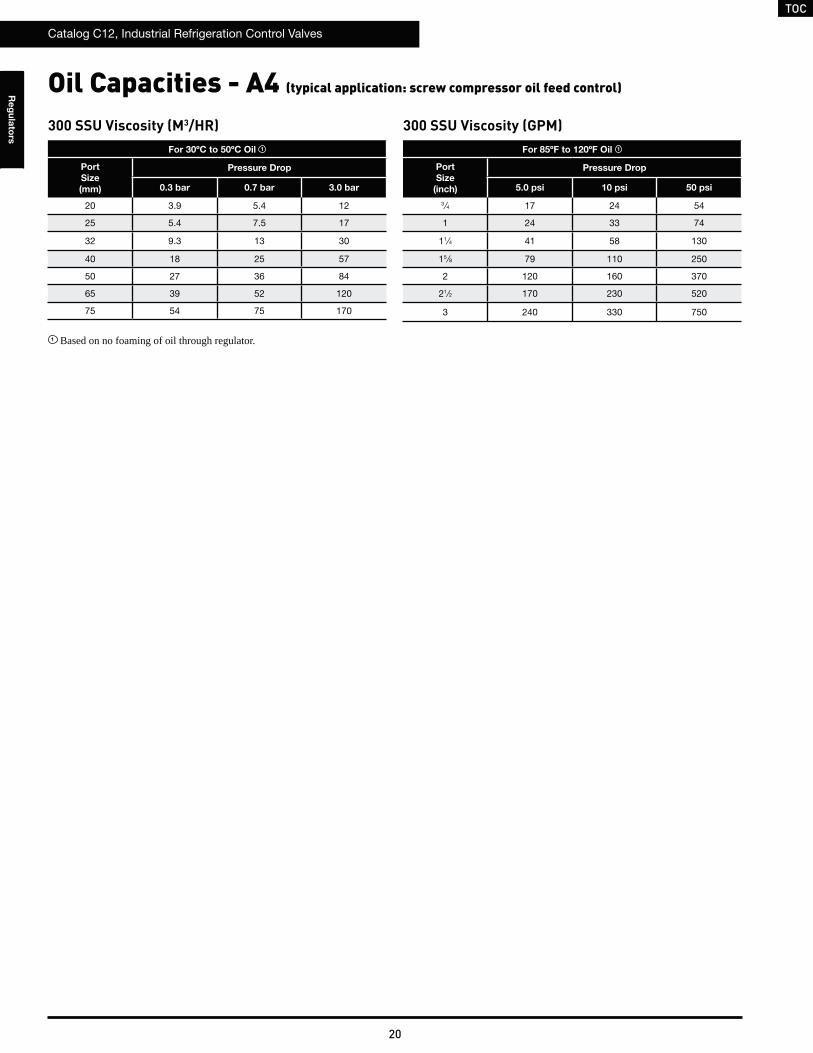
Oil Capacities - A4 (typical application: screw compressor oil feed control)
300 SSU Viscosity (M3/HR)For 30ºC to 50ºC Oil 1
Port
Size
(mm)
Pressure Drop
0.3 bar 0.7 bar 3.0 bar
20 3.9 5.4 12
25 5.4 7.5 17
32 9.3 13 30
40 18 25 57
50 27 36 84
65 39 52 120
75 54 75 170
1 Based on no foaming of oil through regulator.
300 SSU Viscosity (GPM)For 85ºF to 120ºF Oil 1
Port
Size
(inch)
Pressure Drop
5.0 psi 10 psi 50 psi
3 ⁄4 17 24 54
1 24 33 74
11⁄4 41 58 130
15 ⁄8 79 110 250
2 120 160 370
21⁄2 170 230 520
3 240 330 750
TOC
Catalog C12, Industrial Refrigeration Control Valves
21
Re
gu
lato
rs
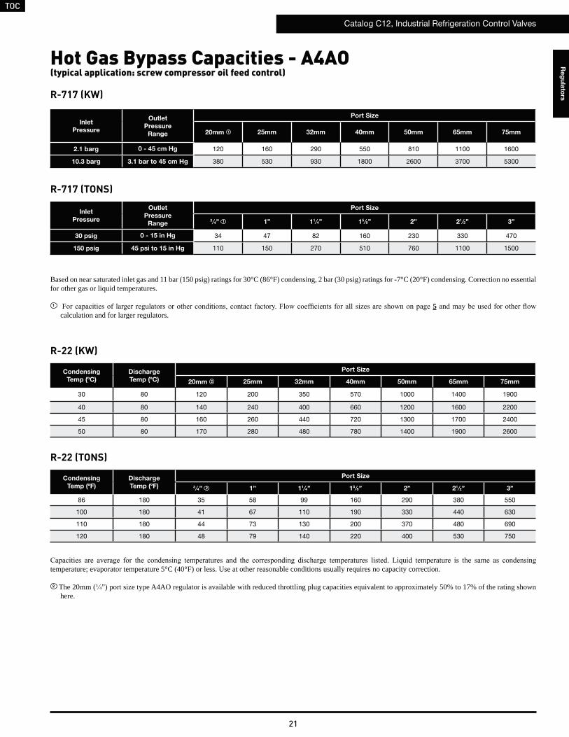
Hot Gas Bypass Capacities - A4AO (typical application: screw compressor oil feed control)
R-22 (KW)
Based on near saturated inlet gas and 11 bar (150 psig) ratings for 30°C (86°F) condensing, 2 bar (30 psig) ratings for -7°C (20°F) condensing. Correction no essential for other gas or liquid temperatures.
1 5calculation and for larger regulators.
R-717 (KW)
temperature; evaporator temperature 5°C (40°F) or less. Use at other reasonable conditions usually requires no capacity correction.
2 The 20mm (3 4”) port size type A4AO regulator is available with reduced throttling plug capacities equivalent to approximately 50% to 17% of the rating shown here.
R-22 (TONS)
R-717 (TONS)
Condensing
Temp (ºF)
Discharge
Temp (ºF)
Port Size
3 ⁄4” 2 1” 11 ⁄4” 15 ⁄8” 2” 21 ⁄2” 3”
86 180 35 58 99 160 290 380 550
100 180 41 67 110 190 330 440 630
110 180 44 73 130 200 370 480 690
120 180 48 79 140 220 400 530 750
Condensing
Temp (ºC)
Discharge
Temp (ºC)
Port Size
20mm 2 25mm 32mm 40mm 50mm 65mm 75mm
30 80 120 200 350 570 1000 1400 1900
40 80 140 240 400 660 1200 1600 2200
45 80 160 260 440 720 1300 1700 2400
50 80 170 280 480 780 1400 1900 2600
Inlet
Pressure
Outlet
Pressure
Range
Port Size
20mm 1 25mm 32mm 40mm 50mm 65mm 75mm
2.1 barg 0 - 45 cm Hg 120 160 290 550 810 1100 1600
10.3 barg 3.1 bar to 45 cm Hg 380 530 930 1800 2600 3700 5300
Inlet
Pressure
Outlet
Pressure
Range
Port Size
3 ⁄4” 1 1” 11 ⁄4” 15 ⁄8” 2” 21 ⁄2” 3”
30 psig 0 - 15 in Hg 34 47 82 160 230 330 470
150 psig 45 psi to 15 in Hg 110 150 270 510 760 1100 1500
TOC
Catalog C12, Industrial Refrigeration Control Valves
22
Re
gu
lato
rs
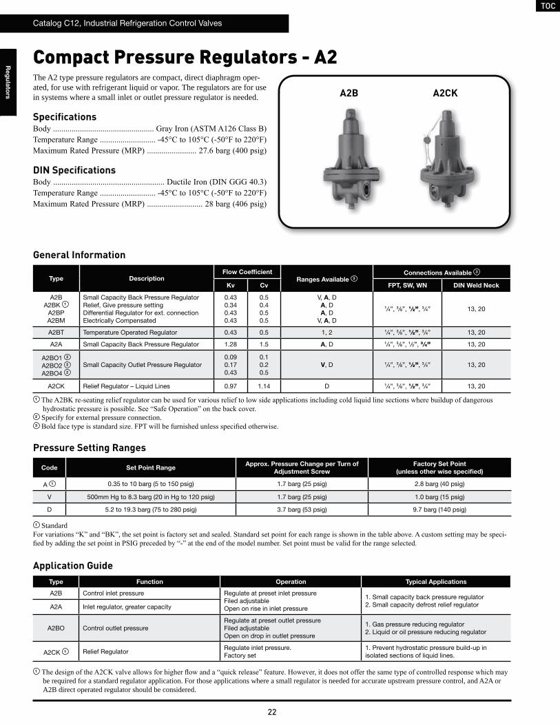
Compact Pressure Regulators - A2
Application Guide
The A2 type pressure regulators are compact, direct diaphragm oper-ated, for use with refrigerant liquid or vapor. The regulators are for use in systems where a small inlet or outlet pressure regulator is needed.
Specifications
DIN Specifications
A2B A2CK
Type Function Operation Typical Applications
A2B Control inlet pressure Regulate at preset inlet pressureFiled adjustableOpen on rise in inlet pressure
1. Small capacity back pressure regulator2. Small capacity defrost relief regulatorA2A Inlet regulator, greater capacity
A2BO Control outlet pressureRegulate at preset outlet pressureFiled adjustableOpen on drop in outlet pressure
1. Gas pressure reducing regulator2. Liquid or oil pressure reducing regulator
A2CK 1 Relief RegulatorRegulate inlet pressure.Factory set
1. Prevent hydrostatic pressure build-up in isolated sections of liquid lines.
Type DescriptionFlow Coefficient
Ranges Available 3
Connections Available 3
Kv Cv FPT, SW, WN DIN Weld Neck
A2BA2BK 1
A2BPA2BM
Small Capacity Back Pressure RegulatorRelief, Give pressure settingDifferential Regulator for ext. connectionElectrically Compensated
0.430.340.430.43
0.50.40.50.5
V, A, DA, DA, D
V, A, D
1 ⁄4”, 3 ⁄8”, 1⁄2”, 3 ⁄4” 13, 20
A2BT Temperature Operated Regulator 0.43 0.5 1, 2 1 ⁄4”, 3 ⁄8”, 1⁄2”, 3 ⁄4” 13, 20
A2A Small Capacity Back Pressure Regulator 1.28 1.5 A, D 1 ⁄4”, 3 ⁄8”, 1 ⁄2”, 3 ⁄4” 13, 20
A2BO1 2
A2BO2 2
A2BO4 2
Small Capacity Outlet Pressure Regulator0.090.170.43
0.10.20.5
V, D 1 ⁄4”, 3 ⁄8”, 1⁄2”, 3 ⁄4” 13, 20
A2CK Relief Regulator – Liquid Lines 0.97 1.14 D 1 ⁄4”, 3 ⁄8”, 1⁄2”, 3 ⁄4” 13, 20
1 be required for a standard regulator application. For those applications where a small regulator is needed for accurate upstream pressure control, and A2A or A2B direct operated regulator should be considered.
Pressure Setting Ranges
1
2 Specify for external pressure connection.3
Code Set Point RangeApprox. Pressure Change per Turn of
Adjustment Screw
Factory Set Point
(unless other wise specified)
A 1 0.35 to 10 barg (5 to 150 psig) 1.7 barg (25 psig) 2.8 barg (40 psig)
V 500mm Hg to 8.3 barg (20 in Hg to 120 psig) 1.7 barg (25 psig) 1.0 barg (15 psig)
D 5.2 to 19.3 barg (75 to 280 psig) 3.7 barg (53 psig) 9.7 barg (140 psig)
1 Standard-
General Information
TOC
Catalog C12, Industrial Refrigeration Control Valves
23
Re
gu
lato
rs
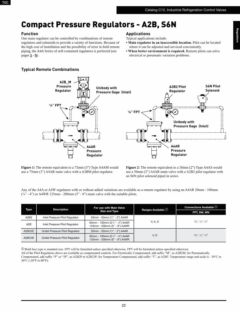
FunctionOne main regulator can be controlled by combinations of remote regulators and solenoids to provide a variety of functions. Because of
piping, the A4A Series of self-contained regulators is preferred (see pages 5 - 9).
Typical Remote Combinations
Compact Pressure Regulators - A2B, S6N
Figure 1: The remote equivalent to a 75mm (3”) Type A4AM would
ApplicationsTypical applications include:
Pilot can be located
electrical or pneumatic variation problems.
Type DescriptionFor use with Main Valve
Size and TypeRanges Available 1
Connections Available 1
FPT, SW, WN
A2B2 Inlet Pressure Pilot Regulator 20mm - 50mm (3 ⁄4” - 2”) A4AR
V, A, D 3 ⁄8”, 1 ⁄2”, 3 ⁄4”A2B Inlet Pressure Pilot Regulator
65mm - 100mm (21⁄2” - 4”) A4AR125mm - 200mm (5” - 8”) A4WR
A2BO2E Outlet Pressure Pilot Regulator 20mm - 50mm (3 ⁄4” - 2”) A4AR
V, D 3 ⁄8”, 1 ⁄2”, 3 ⁄4”A2BO4E Outlet Pressure Pilot Regulator
65mm - 100mm (21⁄2” - 4”) A4AR125mm - 200mm (5” - 8”) A4WR
1
30°C (-20°F to 80°F).
Unibody withPressure Gage (Inlet)
A2B2 PilotRegulator
S6N PilotSolenoid
A4AR Pressure Regulator
A2B_M Pressure
Regulator
3 ⁄8” FPT
3 ⁄8” FPT
A4AR Pressure Regulator
Unibody withPressure Gage (Inlet)
Figure 2: The remote equivalent to a 50mm (2”) Type A4AS would
TOC
Catalog C12, Industrial Refrigeration Control Valves
24
Re
gu
lato
rs
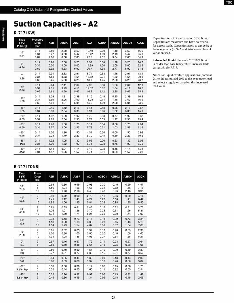
R-717 (KW)Evap
T (ºC)
P (barg)
Pressure
Drop
(bar)
A2B A2BK A2BP A2A A2BO1 A2BO2 A2BO4 A2CK
10º5.14
0.140.340.69
3.505.477.60
2.804.386.08
3.505.477.60
10.4916.4222.8
0.701.091.52
1.402.193.04
3.505.477.60
16.025.134.9
5º4.14
0.140.340.69
3.205.006.92
2.564.005.53
3.205.006.92
9.5914.9920.7
0.641.001.38
1.282.002.77
3.205.006.92
14.722.931.8
0º3.28
0.140.340.69
2.914.546.25
2.333.635.00
2.914.546.25
8.7413.6218.7
0.580.911.25
1.161.822.50
2.914.546.25
13.420.828.7
-5º2.53
0.140.340.69
2.644.115.62
2.113.294.50
2.644.115.62
7.9312.3216.8
0.530.821.12
1.061.642.25
2.644.115.62
12.118.825.8
-10º1.89
0.140.340.69
2.393.695.01
1.912.964.01
2.393.695.01
7.1611.0815.0
0.480.741.00
0.951.482.00
2.393.695.01
10.916.923.0
-15º1.35
0.140.34
2.153.30
1.722.64
2.153.30
6.449.91
0.430.66
0.861.32
2.153.30
9.8715.1
-20º0.89
0.140.34
1.922.93
1.532.34
1.922.93
5.758.79
0.380.59
0.771.17
1.922.93
8.8213.4
-25º0.50
0.140.34
1.702.57
1.362.06
1.702.57
5.117.72
0.340.51
0.681.03
1.702.57
7.8411.8
-30º0.18
0.140.34
1.502.23
1.201.79
1.502.23
4.516.70
0.300.45
0.600.89
1.502.23
6.9210.2
-35º-0.08
0.140.34
1.321.90
1.051.52
1.321.90
3.955.71
0.260.38
0.530.76
1.321.90
6.058.75
-40º-0.30
0.140.34
1.141.57
0.911.26
1.141.57
3.424.71
0.230.31
0.460.63
1.141.57
5.247.23
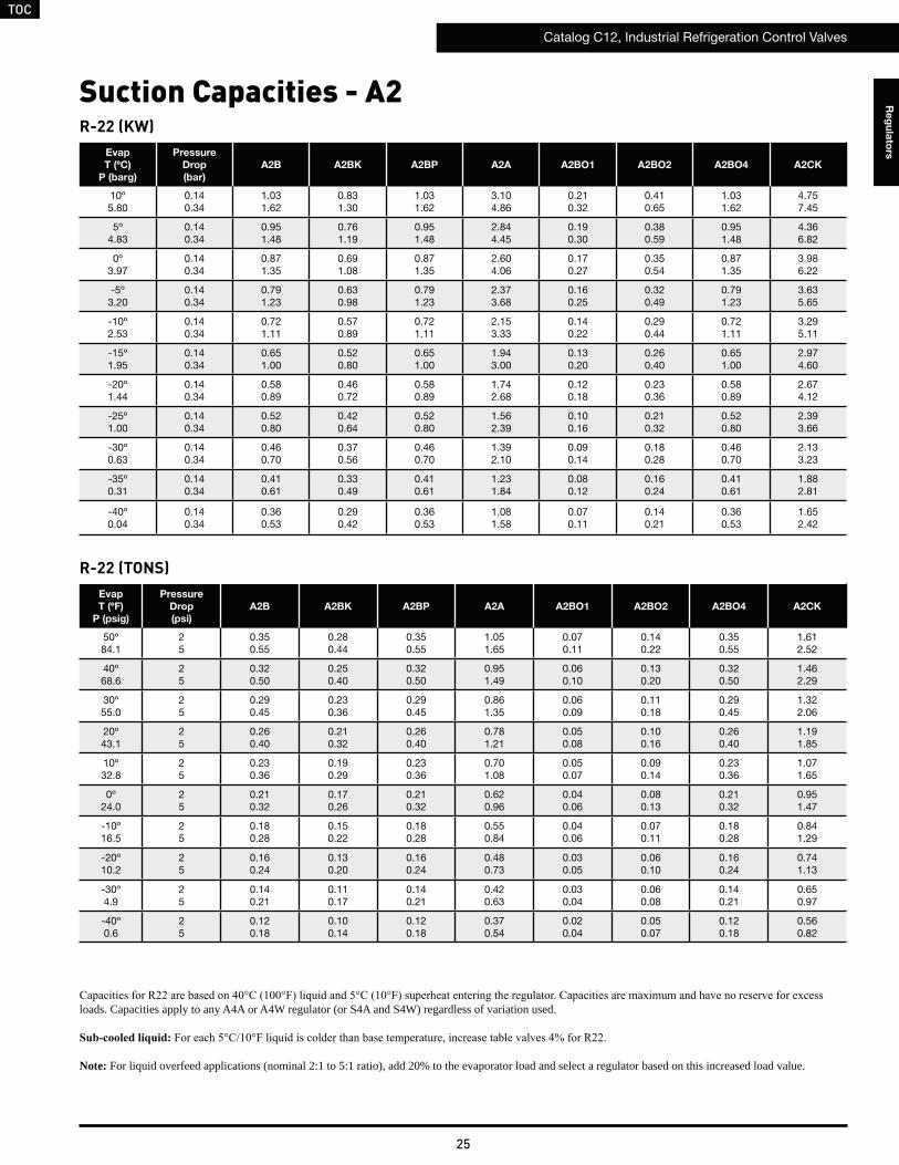
Capacities are maximum and have no reserve for excess loads. Capacities apply to any A4A or A4W regulator (or S4A and S4W) regardless of variation used.
is colder than base temperature, increase table
ote: For liquid overfeed applications (nominal 2:1 to 5:1 ratio), add 20% to the evaporator load and select a regulator based on this increased load value.
Suction Capacities - A2
R-717 (TONS)Evap
T (ºF)
P (psig)
Press
Drop
(psi)
A2B A2BK A2BP A2A A2BO1 A2BO2 A2BO4 A2CK
50º74.5
2510
0.991.562.16
0.801.241.73
0.991.562.16
2.984.676.49
0.200.310.43
0.400.620.86
0.991.562.16
4.577.169.95
40º58.6
2510
0.901.411.95
0.721.121.56
0.901.411.95
2.704.225.84
0.180.280.39
0.360.560.78
0.901.411.95
4.146.478.95
30º45.0
2510
0.811.261.74
0.651.011.39
0.811.261.74
2.433.795.21
0.160.250.35
0.320.510.70
0.811.261.74
3.735.817.99
20º33.5
2510
0.731.131.54
0.580.901.23
0.731.131.54
2.183.384.62
0.150.230.31
0.290.450.62
0.731.131.54
3.345.197.08
10º23.8
2510
0.651.001.35
0.520.801.08
0.651.001.35
1.943.004.05
0.130.200.27
0.260.400.54
0.651.001.35
2.984.606.21
0º15.7
25
0.570.88
0.460.70
0.570.88
1.722.64
0.110.18
0.230.35
0.570.88
2.644.05
-10º9.0
25
0.500.77
0.400.61
0.500.77
1.512.30
0.100.15
0.200.31
0.500.77
2.323.52
-20º3.6
25
0.440.66
0.350.53
0.440.66
1.321.97
0.090.13
0.180.26
0.440.66
2.023.02
-30º1.6 in Hg
25
0.380.55
0.300.44
0.380.55
1.141.65
0.080.11
0.150.22
0.380.55
1.752.54
-40º8.8 in Hg
25
0.320.45
0.260.36
0.320.45
0.971.34
0.060.09
0.130.18
0.320.45
1.492.06
TOC
Catalog C12, Industrial Refrigeration Control Valves
25
Re
gu
lato
rs
R-22 (KW)Evap
T (ºC)
P (barg)
Pressure
Drop
(bar)
A2B A2BK A2BP A2A A2BO1 A2BO2 A2BO4 A2CK
10º5.80
0.140.34
1.031.62
0.831.30
1.031.62
3.104.86
0.210.32
0.410.65
1.031.62
4.757.45
5º4.83
0.140.34
0.951.48
0.761.19
0.951.48
2.844.45
0.190.30
0.380.59
0.951.48
4.366.82
0º3.97
0.140.34
0.871.35
0.691.08
0.871.35
2.604.06
0.170.27
0.350.54
0.871.35
3.986.22
-5º3.20
0.140.34
0.791.23
0.630.98
0.791.23
2.373.68
0.160.25
0.320.49
0.791.23
3.635.65
-10º2.53
0.140.34
0.721.11
0.570.89
0.721.11
2.153.33
0.140.22
0.290.44
0.721.11
3.295.11
-15º1.95
0.140.34
0.651.00
0.520.80
0.651.00
1.943.00
0.130.20
0.260.40
0.651.00
2.974.60
-20º1.44
0.140.34
0.580.89
0.460.72
0.580.89
1.742.68
0.120.18
0.230.36
0.580.89
2.674.12
-25º1.00
0.140.34
0.520.80
0.420.64
0.520.80
1.562.39
0.100.16
0.210.32
0.520.80
2.393.66
-30º0.63
0.140.34
0.460.70
0.370.56
0.460.70
1.392.10
0.090.14
0.180.28
0.460.70
2.133.23
-35º0.31
0.140.34
0.410.61
0.330.49
0.410.61
1.231.84
0.080.12
0.160.24
0.410.61
1.882.81
-40º0.04
0.140.34
0.360.53
0.290.42
0.360.53
1.081.58
0.070.11
0.140.21
0.360.53
1.652.42
R-22 (TONS)Evap
T (ºF)
P (psig)
Pressure
Drop
(psi)
A2B A2BK A2BP A2A A2BO1 A2BO2 A2BO4 A2CK
50º84.1
25
0.350.55
0.280.44
0.350.55
1.051.65
0.070.11
0.140.22
0.350.55
1.612.52
40º68.6
25
0.320.50
0.250.40
0.320.50
0.951.49
0.060.10
0.130.20
0.320.50
1.462.29
30º55.0
25
0.290.45
0.230.36
0.290.45
0.861.35
0.060.09
0.110.18
0.290.45
1.322.06
20º43.1
25
0.260.40
0.210.32
0.260.40
0.781.21
0.050.08
0.100.16
0.260.40
1.191.85
10º32.8
25
0.230.36
0.190.29
0.230.36
0.701.08
0.050.07
0.090.14
0.230.36
1.071.65
0º24.0
25
0.210.32
0.170.26
0.210.32
0.620.96
0.040.06
0.080.13
0.210.32
0.951.47
-10º16.5
25
0.180.28
0.150.22
0.180.28
0.550.84
0.040.06
0.070.11
0.180.28
0.841.29
-20º10.2
25
0.160.24
0.130.20
0.160.24
0.480.73
0.030.05
0.060.10
0.160.24
0.741.13
-30º4.9
25
0.140.21
0.110.17
0.140.21
0.420.63
0.030.04
0.060.08
0.140.21
0.650.97
-40º0.6
25
0.120.18
0.100.14
0.120.18
0.370.54
0.020.04
0.050.07
0.120.18
0.560.82
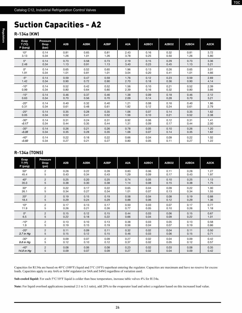
loads. Capacities apply to any A4A or A4W regulator (or S4A and S4W) regardless of variation used.
Note: For liquid overfeed applications (nominal 2:1 to 5:1 ratio), add 20% to the evaporator load and select a regulator based on this increased load value.
Suction Capacities - A2
TOC
Catalog C12, Industrial Refrigeration Control Valves
26
Re
gu
lato
rs
Suction Capacities - A2R-134a (KW)
Evap
T (ºC)
P (barg)
Pressure
Drop
(bar)
A2B A2BK A2BP A2A A2BO1 A2BO2 A2BO4 A2CK
10º3.13
0.140.34
0.811.26
0.651.01
0.811.26
2.433.78
0.160.25
0.320.50
0.811.26
3.725.80
5º2.48
0.140.34
0.731.13
0.580.91
0.731.13
2.193.40
0.150.23
0.290.45
0.731.13
3.365.21
0º1.91
0.140.34
0.651.01
0.520.81
0.651.01
1.963.04
0.130.20
0.260.41
0.651.01
3.014.66
-5º1.42
0.140.34
0.590.90
0.470.72
0.590.90
1.762.70
0.120.18
0.230.36
0.590.90
2.694.14
-10º0.99
0.140.34
0.520.80
0.420.64
0.520.80
1.562.39
0.100.16
0.210.32
0.520.80
2.393.66
-15º0.63
0.140.34
0.460.70
0.370.56
0.460.70
1.382.09
0.090.14
0.180.28
0.460.70
2.123.21
-20º0.31
0.140.34
0.400.61
0.320.48
0.400.61
1.211.82
0.080.12
0.160.24
0.400.61
1.862.79
-25º0.05
0.140.34
0.350.52
0.280.41
0.350.52
1.061.56
0.070.10
0.140.21
0.350.52
1.622.38
-30º-0.17
0.140.34
0.310.44
0.240.35
0.310.44
0.921.31
0.060.09
0.120.17
0.310.44
1.412.00
-35º-0.35
0.140.34
0.260.35
0.210.28
0.260.35
0.781.06
0.050.07
0.100.14
0.260.35
1.201.62
-40º-0.50
0.140.34
0.220.27
0.180.21
0.220.27
0.660.80
0.040.05
0.090.11
0.220.27
1.021.22
R-134a (TONS)Evap
T (ºF)
P (psig)
Pressure
Drop
(psi)
A2B A2BK A2BP A2A A2BO1 A2BO2 A2BO4 A2CK
50º45.4
25
0.280.43
0.220.34
0.280.43
0.831.29
0.060.09
0.110.17
0.280.43
1.271.97
40º35.0
25
0.250.38
0.200.30
0.250.38
0.741.14
0.050.08
0.100.15
0.250.38
1.131.75
30º26.1
25
0.220.34
0.170.27
0.220.34
0.651.01
0.040.07
0.090.13
0.220.34
1.001.55
20º18.4
25
0.190.29
0.150.24
0.190.29
0.580.88
0.040.06
0.080.12
0.190.29
0.881.36
10º11.9
25
0.170.26
0.130.21
0.170.26
0.500.77
0.030.05
0.070.10
0.170.26
0.771.18
0º6.5
25
0.150.22
0.120.18
0.150.22
0.440.66
0.030.04
0.060.09
0.150.22
0.671.01
-10º1.9
25
0.130.19
0.100.15
0.130.19
0.380.56
0.030.04
0.050.07
0.130.19
0.580.86
-20º3.7 in Hg
25
0.110.15
0.090.12
0.110.15
0.320.46
0.020.03
0.040.06
0.110.15
0.500.71
-30º9.8 in Hg
25
0.090.12
0.070.10
0.090.12
0.270.37
0.020.02
0.040.05
0.090.12
0.420.57
-40º14.8 in Hg
25
0.080.09
0.060.07
0.080.09
0.230.27
0.020.02
0.030.04
0.080.09
0.350.42
loads. Capacities apply to any A4A or A4W regulator (or S4A and S4W) regardless of variation used.
Note: For liquid overfeed applications (nominal 2:1 to 5:1 ratio), add 20% to the evaporator load and select a regulator based on this increased load value.
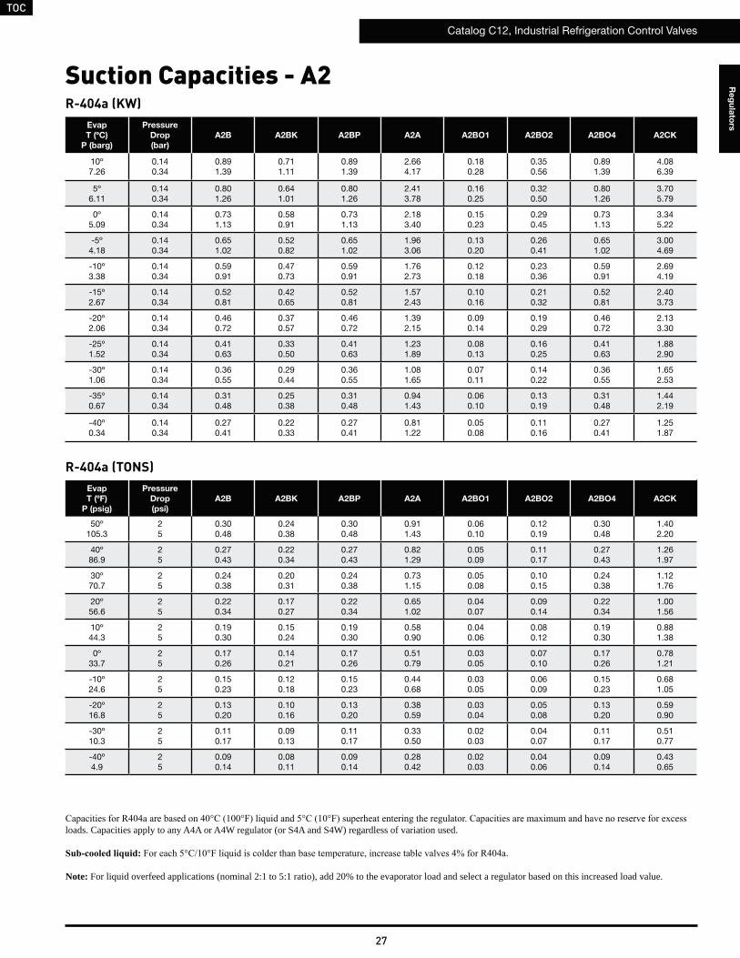
TOC
Catalog C12, Industrial Refrigeration Control Valves
27
Re
gu
lato
rs
Suction Capacities - A2R-404a (KW)
Evap
T (ºC)
P (barg)
Pressure
Drop
(bar)
A2B A2BK A2BP A2A A2BO1 A2BO2 A2BO4 A2CK
10º7.26
0.140.34
0.891.39
0.711.11
0.891.39
2.664.17
0.180.28
0.350.56
0.891.39
4.086.39
5º6.11
0.140.34
0.801.26
0.641.01
0.801.26
2.413.78
0.160.25
0.320.50
0.801.26
3.705.79
0º5.09
0.140.34
0.731.13
0.580.91
0.731.13
2.183.40
0.150.23
0.290.45
0.731.13
3.345.22
-5º4.18
0.140.34
0.651.02
0.520.82
0.651.02
1.963.06
0.130.20
0.260.41
0.651.02
3.004.69
-10º3.38
0.140.34
0.590.91
0.470.73
0.590.91
1.762.73
0.120.18
0.230.36
0.590.91
2.694.19
-15º2.67
0.140.34
0.520.81
0.420.65
0.520.81
1.572.43
0.100.16
0.210.32
0.520.81
2.403.73
-20º2.06
0.140.34
0.460.72
0.370.57
0.460.72
1.392.15
0.090.14
0.190.29
0.460.72
2.133.30
-25º1.52
0.140.34
0.410.63
0.330.50
0.410.63
1.231.89
0.080.13
0.160.25
0.410.63
1.882.90
-30º1.06
0.140.34
0.360.55
0.290.44
0.360.55
1.081.65
0.070.11
0.140.22
0.360.55
1.652.53
-35º0.67
0.140.34
0.310.48
0.250.38
0.310.48
0.941.43
0.060.10
0.130.19
0.310.48
1.442.19
-40º0.34
0.140.34
0.270.41
0.220.33
0.270.41
0.811.22
0.050.08
0.110.16
0.270.41
1.251.87
R-404a (TONS)Evap
T (ºF)
P (psig)
Pressure
Drop
(psi)
A2B A2BK A2BP A2A A2BO1 A2BO2 A2BO4 A2CK
50º105.3
25
0.300.48
0.240.38
0.300.48
0.911.43
0.060.10
0.120.19
0.300.48
1.402.20
40º86.9
25
0.270.43
0.220.34
0.270.43
0.821.29
0.050.09
0.110.17
0.270.43
1.261.97
30º70.7
25
0.240.38
0.200.31
0.240.38
0.731.15
0.050.08
0.100.15
0.240.38
1.121.76
20º56.6
25
0.220.34
0.170.27
0.220.34
0.651.02
0.040.07
0.090.14
0.220.34
1.001.56
10º44.3
25
0.190.30
0.150.24
0.190.30
0.580.90
0.040.06
0.080.12
0.190.30
0.881.38
0º33.7
25
0.170.26
0.140.21
0.170.26
0.510.79
0.030.05
0.070.10
0.170.26
0.781.21
-10º24.6
25
0.150.23
0.120.18
0.150.23
0.440.68
0.030.05
0.060.09
0.150.23
0.681.05
-20º16.8
25
0.130.20
0.100.16
0.130.20
0.380.59
0.030.04
0.050.08
0.130.20
0.590.90
-30º10.3
25
0.110.17
0.090.13
0.110.17
0.330.50
0.020.03
0.040.07
0.110.17
0.510.77
-40º4.9
25
0.090.14
0.080.11
0.090.14
0.280.42
0.020.03
0.040.06
0.090.14
0.430.65
loads. Capacities apply to any A4A or A4W regulator (or S4A and S4W) regardless of variation used.
Note: For liquid overfeed applications (nominal 2:1 to 5:1 ratio), add 20% to the evaporator load and select a regulator based on this increased load value.
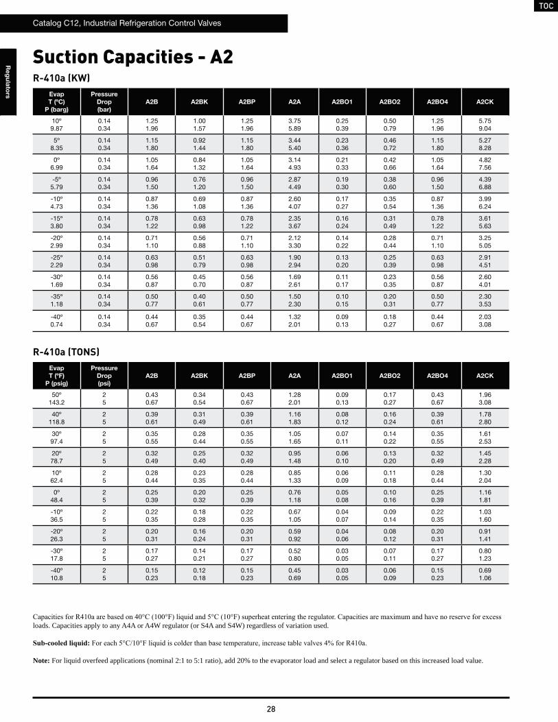
TOC
Catalog C12, Industrial Refrigeration Control Valves
28
Re
gu
lato
rs
R-410a (KW)Evap
T (ºC)
P (barg)
Pressure
Drop
(bar)
A2B A2BK A2BP A2A A2BO1 A2BO2 A2BO4 A2CK
10º9.87
0.140.34
1.251.96
1.001.57
1.251.96
3.755.89
0.250.39
0.500.79
1.251.96
5.759.04
5º8.35
0.140.34
1.151.80
0.921.44
1.151.80
3.445.40
0.230.36
0.460.72
1.151.80
5.278.28
0º6.99
0.140.34
1.051.64
0.841.32
1.051.64
3.144.93
0.210.33
0.420.66
1.051.64
4.827.56
-5º5.79
0.140.34
0.961.50
0.761.20
0.961.50
2.874.49
0.190.30
0.380.60
0.961.50
4.396.88
-10º4.73
0.140.34
0.871.36
0.691.08
0.871.36
2.604.07
0.170.27
0.350.54
0.871.36
3.996.24
-15º3.80
0.140.34
0.781.22
0.630.98
0.781.22
2.353.67
0.160.24
0.310.49
0.781.22
3.615.63
-20º2.99
0.140.34
0.711.10
0.560.88
0.711.10
2.123.30
0.140.22
0.280.44
0.711.10
3.255.05
-25º2.29
0.140.34
0.630.98
0.510.79
0.630.98
1.902.94
0.130.20
0.250.39
0.630.98
2.914.51
-30º1.69
0.140.34
0.560.87
0.450.70
0.560.87
1.692.61
0.110.17
0.230.35
0.560.87
2.604.01
-35º1.18
0.140.34
0.500.77
0.400.61
0.500.77
1.502.30
0.100.15
0.200.31
0.500.77
2.303.53
-40º0.74
0.140.34
0.440.67
0.350.54
0.440.67
1.322.01
0.090.13
0.180.27
0.440.67
2.033.08
R-410a (TONS)Evap
T (ºF)
P (psig)
Pressure
Drop
(psi)
A2B A2BK A2BP A2A A2BO1 A2BO2 A2BO4 A2CK
50º143.2
25
0.430.67
0.340.54
0.430.67
1.282.01
0.090.13
0.170.27
0.430.67
1.963.08
40º118.8
25
0.390.61
0.310.49
0.390.61
1.161.83
0.080.12
0.160.24
0.390.61
1.782.80
30º97.4
25
0.350.55
0.280.44
0.350.55
1.051.65
0.070.11
0.140.22
0.350.55
1.612.53
20º78.7
25
0.320.49
0.250.40
0.320.49
0.951.48
0.060.10
0.130.20
0.320.49
1.452.28
10º62.4
25
0.280.44
0.230.35
0.280.44
0.851.33
0.060.09
0.110.18
0.280.44
1.302.04
0º48.4
25
0.250.39
0.200.32
0.250.39
0.761.18
0.050.08
0.100.16
0.250.39
1.161.81
-10º36.5
25
0.220.35
0.180.28
0.220.35
0.671.05
0.040.07
0.090.14
0.220.35
1.031.60
-20º26.3
25
0.200.31
0.160.24
0.200.31
0.590.92
0.040.06
0.080.12
0.200.31
0.911.41
-30º17.8
25
0.170.27
0.140.21
0.170.27
0.520.80
0.030.05
0.070.11
0.170.27
0.801.23
-40º10.8
25
0.150.23
0.120.18
0.150.23
0.450.69
0.030.05
0.060.09
0.150.23
0.691.06
loads. Capacities apply to any A4A or A4W regulator (or S4A and S4W) regardless of variation used.
Note: For liquid overfeed applications (nominal 2:1 to 5:1 ratio), add 20% to the evaporator load and select a regulator based on this increased load value.
Suction Capacities - A2
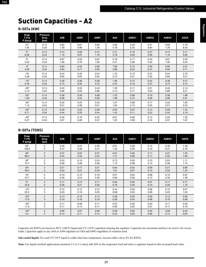
TOC
Catalog C12, Industrial Refrigeration Control Valves
29
Re
gu
lato
rs
R-507a (KW)Evap
T (ºC)
P (barg)
Pressure
Drop
(bar)
A2B A2BK A2BP A2A A2BO1 A2BO2 A2BO4 A2CK
10º7.45
0.140.34
0.821.29
0.610.96
0.821.29
2.664.18
0.200.32
0.410.64
0.821.29
4.106.43
5º6.28
0.140.34
0.741.16
0.560.87
0.741.16
2.413.78
0.190.29
0.370.58
0.741.16
3.715.82
0º5.23
0.140.34
0.671.05
0.500.79
0.671.05
2.183.41
0.170.26
0.340.52
0.671.05
3.355.24
-5º4.30
0.140.34
0.600.94
0.450.71
0.600.94
1.963.06
0.150.24
0.300.47
0.600.94
3.014.71
-10º3.48
0.140.34
0.540.84
0.400.63
0.540.84
1.752.73
0.130.21
0.270.42
0.540.84
2.704.21
-15º2.76
0.140.34
0.480.75
0.360.56
0.480.75
1.562.43
0.120.19
0.240.37
0.480.75
2.413.74
-20º2.13
0.140.34
0.430.66
0.320.50
0.430.66
1.392.15
0.110.17
0.210.33
0.430.66
2.143.31
-25º1.59
0.140.34
0.380.58
0.280.44
0.380.58
1.221.89
0.090.15
0.190.29
0.380.58
1.882.91
-30º1.12
0.140.34
0.330.51
0.250.38
0.330.51
1.071.65
0.080.13
0.170.25
0.330.51
1.652.53
-35º0.71
0.140.34
0.290.44
0.220.33
0.290.44
0.941.42
0.070.11
0.140.22
0.290.44
1.442.19
-40º0.37
0.140.34
0.250.37
0.190.28
0.250.37
0.811.22
0.060.09
0.120.19
0.250.37
1.251.87
R-507a (TONS)Evap
T (ºF)
P (psig)
Pressure
Drop
(psi)
A2B A2BK A2BP A2A A2BO1 A2BO2 A2BO4 A2CK
50º108.0
25
0.300.47
0.240.38
0.300.47
0.911.42
0.060.09
0.120.19
0.300.47
1.392.18
40º89.2
25
0.270.42
0.220.34
0.270.42
0.811.27
0.050.08
0.110.17
0.270.42
1.251.95
30º72.7
25
0.240.38
0.190.30
0.240.38
0.731.13
0.050.08
0.100.15
0.240.38
1.111.74
20º58.3
25
0.210.34
0.170.27
0.210.34
0.641.01
0.040.07
0.090.13
0.210.34
0.991.54
10º45.7
25
0.190.30
0.150.24
0.190.30
0.570.89
0.040.06
0.080.12
0.190.30
0.871.36
0º34.8
25
0.170.26
0.130.21
0.170.26
0.500.78
0.030.05
0.070.10
0.170.26
0.771.19
-10º25.5
25
0.150.23
0.120.18
0.150.23
0.440.68
0.030.05
0.060.09
0.150.23
0.671.04
-20º17.6
25
0.130.19
0.100.16
0.130.19
0.380.58
0.030.04
0.050.08
0.130.19
0.580.89
-30º11.0
25
0.110.17
0.090.13
0.110.17
0.330.50
0.020.03
0.040.07
0.110.17
0.500.76
-40º5.4
25
0.090.14
0.070.11
0.090.14
0.280.42
0.020.03
0.040.06
0.090.14
0.430.64
loads. Capacities apply to any A4A or A4W regulator (or S4A and S4W) regardless of variation used.
Note: For liquid overfeed applications (nominal 2:1 to 5:1 ratio), add 20% to the evaporator load and select a regulator based on this increased load value.
Suction Capacities - A2

TOC
Catalog C12, Industrial Refrigeration Control Valves
30
Re
gu
lato
rs
R-717 (KG/MIN & M3/HR)Liquid
Temp
(ºC)
Press.
Drop
(bar)
A2B A2BK A2BP A2A A2BO1 A2BO2 A2BO4 A2CK
kg/min m3/hr kg/min m3/hr kg/min m3/hr kg/min m3/hr kg/min m3/hr kg/min m3/hr kg/min m3/hr kg/min m3/hr
5º-20º-40º
0.694.44.54.6
0.40.40.4
3.33.43.4
0.30.30.3
4.44.54.6
0.40.40.4
141515
1.41.31.3
1.11.11.1
0.10.10.1
2.22.32.3
0.20.20.2
4.44.54.6
0.40.40.4
222323
2.12.02.0
5º-20º-40º
1.035.45.55.6
0.50.50.5
4.04.14.2
0.40.40.4
5.45.55.6
0.50.50.5
181818
1.71.61.6
1.31.41.4
0.10.10.1
2.72.82.8
0.30.20.2
5.45.55.6
0.50.50.5
272828
2.62.52.4
5º-20º-40º
1.386.26.46.5
0.60.60.6
4.74.84.9
0.40.40.4
6.26.46.5
0.60.60.6
202121
1.91.91.8
1.61.61.6
0.10.10.1
3.13.23.3
0.30.30.3
6.26.46.5
0.60.60.6
313233
3.02.92.8
Liquid Capacities - A2
R-717 (LB/MIN & GPM)Liquid
Temp
(ºF)
Press.
Drop
(psi)
A2B A2BK A2BP A2A A2BO1 A2BO2 A2BO4 A2CK
lb/min gpm lb/min gpm lb/min gpm lb/min gpm lb/min gpm lb/min gpm lb/min gpm lb/min gpm
40º0º
-40º10
101111
2.01.91.9
8.48.68.8
1.61.61.5
101111
2.01.91.9
313233
6.05.85.7
2.12.12.2
0.40.40.4
4.24.34.4
0.80.80.8
101111
2.01.91.9
484950
9.18.98.8
40º0º
-40º15
131313
2.42.42.3
101111
1.91.91.9
131313
2.42.42.3
393940
7.37.17.0
2.62.62.7
0.50.50.5
5.15.35.4
1.01.00.9
131313
2.42.42.3
596062
111111
40º0º
-40º20
151515
2.82.72.7
121212
2.22.22.2
151515
2.82.72.7
444646
8.48.28.1
3.03.03.1
0.60.50.5
5.96.16.2
1.11.11.1
151515
2.82.72.7
687071
131312
R-22 (KG/MIN & M3/HR)Liquid
Temp
(ºC)
Press.
Drop
(bar)
A2B A2BK A2BP A2A A2BO1 A2BO2 A2BO4 A2CK
kg/min m3/hr kg/min m3/hr kg/min m3/hr kg/min m3/hr kg/min m3/hr kg/min m3/hr kg/min m3/hr kg/min m3/hr
5º-20º-40º
0.696.26.46.6
0.30.30.3
4.74.84.9
0.20.20.2
6.26.46.6
0.30.30.3
202121
1.00.90.9
1.61.61.6
0.10.10.1
3.13.23.3
0.10.10.1
6.26.46.6
0.30.30.3
313233
1.51.41.4
5º-20º-40º
1.037.67.98.0
0.40.40.3
5.75.96.0
0.30.30.3
7.67.98.0
0.40.40.3
252626
1.21.11.1
1.92.02.0
0.10.10.1
3.83.94.0
0.20.20.2
7.67.98.0
0.40.40.3
383940
1.81.81.7
5º-20º-40º
1.388.89.19.3
0.40.40.4
6.66.87.0
0.30.30.3
8.89.19.3
0.40.40.4
293030
1.41.31.3
2.22.32.3
0.10.10.1
4.44.54.6
0.20.20.2
8.89.19.3
0.40.40.4
444546
2.12.02.0
R-22 (LB/MIN & GPM)Liquid
Temp
(ºF)
Press.
Drop
(psi)
A2B A2BK A2BP A2A A2BO1 A2BO2 A2BO4 A2CK
lb/min gpm lb/min gpm lb/min gpm lb/min gpm lb/min gpm lb/min gpm lb/min gpm lb/min gpm
40º0º
-40º10
151516
1.41.41.3
121213
1.11.11.1
151516
1.41.41.3
454647
4.24.14.0
3.03.13.1
0.30.30.3
5.96.16.3
0.60.50.5
151516
1.41.41.3
687072
6.56.36.1
40º0º
-40º15
181919
1.71.71.6
151515
1.41.31.3
181919
1.71.71.6
555657
5.25.04.9
3.63.73.8
0.30.30.3
7.37.57.7
0.70.70.7
181919
1.71.71.6
848688
7.97.77.5
40º0º
-40º20
212222
2.01.91.9
171718
1.61.51.5
212222
2.01.91.9
636566
6.05.85.7
4.24.34.4
0.40.40.4
8.48.68.8
0.80.80.8
212222
2.01.91.9
9799
102
9.18.98.7
For evaporator temperatures between 4°C to -40°C (40°F to -40°F), capacities are within 5%.Correction factors for temperatures between -40°C (-40°F) and 30°C (86°F) are negligible.
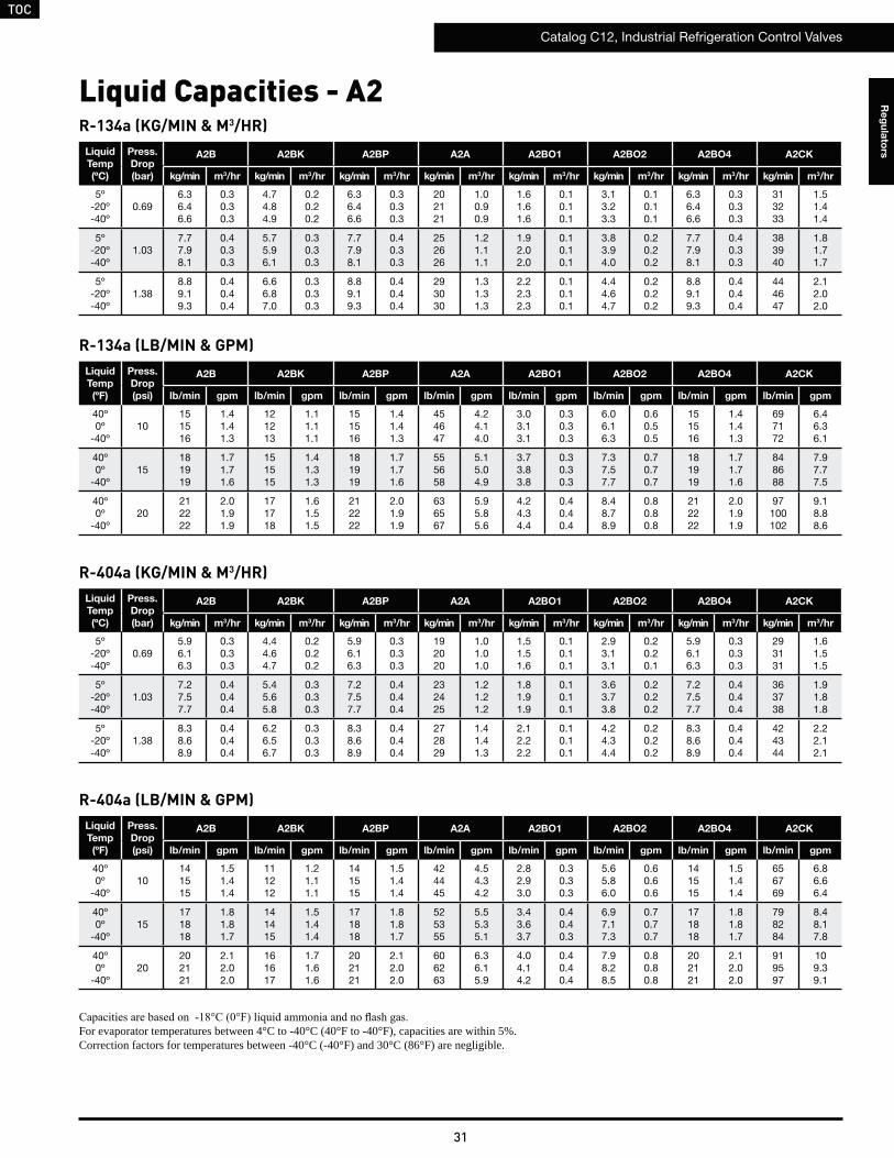
TOC
Catalog C12, Industrial Refrigeration Control Valves
31
Re
gu
lato
rs
Liquid Capacities - A2R-134a (KG/MIN & M3/HR)
Liquid
Temp
(ºC)
Press.
Drop
(bar)
A2B A2BK A2BP A2A A2BO1 A2BO2 A2BO4 A2CK
kg/min m3/hr kg/min m3/hr kg/min m3/hr kg/min m3/hr kg/min m3/hr kg/min m3/hr kg/min m3/hr kg/min m3/hr
5º-20º-40º
0.696.36.46.6
0.30.30.3
4.74.84.9
0.20.20.2
6.36.46.6
0.30.30.3
202121
1.00.90.9
1.61.61.6
0.10.10.1
3.13.23.3
0.10.10.1
6.36.46.6
0.30.30.3
313233
1.51.41.4
5º-20º-40º
1.037.77.98.1
0.40.30.3
5.75.96.1
0.30.30.3
7.77.98.1
0.40.30.3
252626
1.21.11.1
1.92.02.0
0.10.10.1
3.83.94.0
0.20.20.2
7.77.98.1
0.40.30.3
383940
1.81.71.7
5º-20º-40º
1.388.89.19.3
0.40.40.4
6.66.87.0
0.30.30.3
8.89.19.3
0.40.40.4
293030
1.31.31.3
2.22.32.3
0.10.10.1
4.44.64.7
0.20.20.2
8.89.19.3
0.40.40.4
444647
2.12.02.0
R-134a (LB/MIN & GPM)Liquid
Temp
(ºF)
Press.
Drop
(psi)
A2B A2BK A2BP A2A A2BO1 A2BO2 A2BO4 A2CK
lb/min gpm lb/min gpm lb/min gpm lb/min gpm lb/min gpm lb/min gpm lb/min gpm lb/min gpm
40º0º
-40º10
151516
1.41.41.3
121213
1.11.11.1
151516
1.41.41.3
454647
4.24.14.0
3.03.13.1
0.30.30.3
6.06.16.3
0.60.50.5
151516
1.41.41.3
697172
6.46.36.1
40º0º
-40º15
181919
1.71.71.6
151515
1.41.31.3
181919
1.71.71.6
555658
5.15.04.9
3.73.83.8
0.30.30.3
7.37.57.7
0.70.70.7
181919
1.71.71.6
848688
7.97.77.5
40º0º
-40º20
212222
2.01.91.9
171718
1.61.51.5
212222
2.01.91.9
636567
5.95.85.6
4.24.34.4
0.40.40.4
8.48.78.9
0.80.80.8
212222
2.01.91.9
97100102
9.18.88.6
R-404a (KG/MIN & M3/HR)Liquid
Temp
(ºC)
Press.
Drop
(bar)
A2B A2BK A2BP A2A A2BO1 A2BO2 A2BO4 A2CK
kg/min m3/hr kg/min m3/hr kg/min m3/hr kg/min m3/hr kg/min m3/hr kg/min m3/hr kg/min m3/hr kg/min m3/hr
5º-20º-40º
0.695.96.16.3
0.30.30.3
4.44.64.7
0.20.20.2
5.96.16.3
0.30.30.3
192020
1.01.01.0
1.51.51.6
0.10.10.1
2.93.13.1
0.20.20.1
5.96.16.3
0.30.30.3
293131
1.61.51.5
5º-20º-40º
1.037.27.57.7
0.40.40.4
5.45.65.8
0.30.30.3
7.27.57.7
0.40.40.4
232425
1.21.21.2
1.81.91.9
0.10.10.1
3.63.73.8
0.20.20.2
7.27.57.7
0.40.40.4
363738
1.91.81.8
5º-20º-40º
1.388.38.68.9
0.40.40.4
6.26.56.7
0.30.30.3
8.38.68.9
0.40.40.4
272829
1.41.41.3
2.12.22.2
0.10.10.1
4.24.34.4
0.20.20.2
8.38.68.9
0.40.40.4
424344
2.22.12.1
R-404a (LB/MIN & GPM)Liquid
Temp
(ºF)
Press.
Drop
(psi)
A2B A2BK A2BP A2A A2BO1 A2BO2 A2BO4 A2CK
lb/min gpm lb/min gpm lb/min gpm lb/min gpm lb/min gpm lb/min gpm lb/min gpm lb/min gpm
40º0º
-40º10
141515
1.51.41.4
111212
1.21.11.1
141515
1.51.41.4
424445
4.54.34.2
2.82.93.0
0.30.30.3
5.65.86.0
0.60.60.6
141515
1.51.41.4
656769
6.86.66.4
40º0º
-40º15
171818
1.81.81.7
141415
1.51.41.4
171818
1.81.81.7
525355
5.55.35.1
3.43.63.7
0.40.40.3
6.97.17.3
0.70.70.7
171818
1.81.81.7
798284
8.48.17.8
40º0º
-40º20
202121
2.12.02.0
161617
1.71.61.6
202121
2.12.02.0
606263
6.36.15.9
4.04.14.2
0.40.40.4
7.98.28.5
0.80.80.8
202121
2.12.02.0
919597
109.39.1
For evaporator temperatures between 4°C to -40°C (40°F to -40°F), capacities are within 5%.Correction factors for temperatures between -40°C (-40°F) and 30°C (86°F) are negligible.
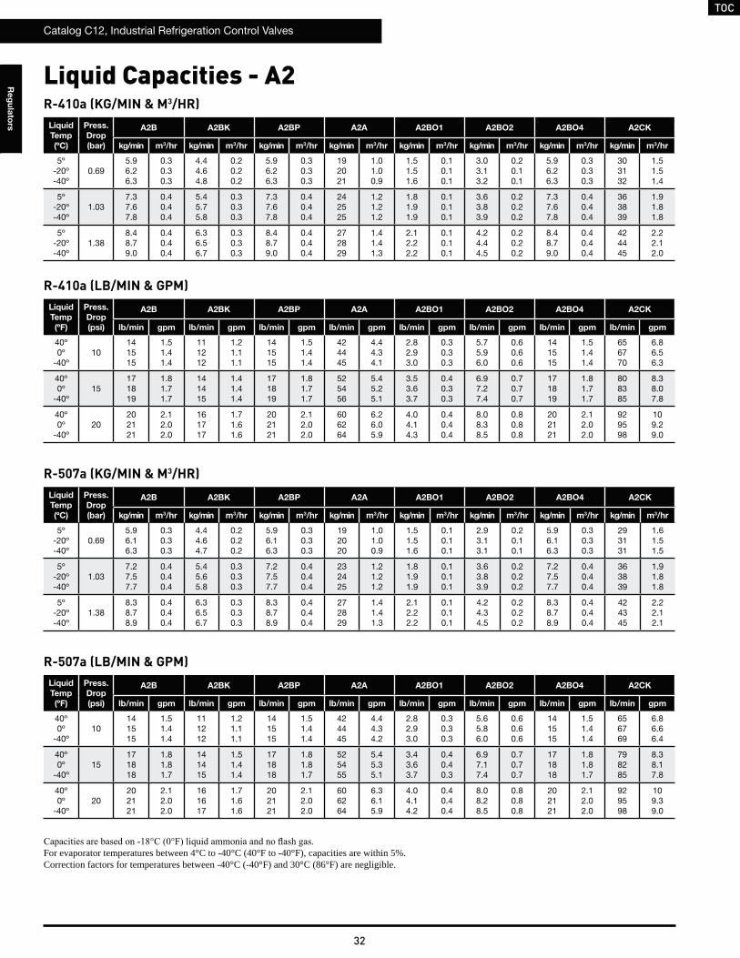
TOC
Catalog C12, Industrial Refrigeration Control Valves
32
Re
gu
lato
rs
Liquid Capacities - A2R-410a (KG/MIN & M3/HR)
Liquid
Temp
(ºC)
Press.
Drop
(bar)
A2B A2BK A2BP A2A A2BO1 A2BO2 A2BO4 A2CK
kg/min m3/hr kg/min m3/hr kg/min m3/hr kg/min m3/hr kg/min m3/hr kg/min m3/hr kg/min m3/hr kg/min m3/hr
5º-20º-40º
0.695.96.26.3
0.30.30.3
4.44.64.8
0.20.20.2
5.96.26.3
0.30.30.3
192021
1.01.00.9
1.51.51.6
0.10.10.1
3.03.13.2
0.20.10.1
5.96.26.3
0.30.30.3
303132
1.51.51.4
5º-20º-40º
1.037.37.67.8
0.40.40.4
5.45.75.8
0.30.30.3
7.37.67.8
0.40.40.4
242525
1.21.21.2
1.81.91.9
0.10.10.1
3.63.83.9
0.20.20.2
7.37.67.8
0.40.40.4
363839
1.91.81.8
5º-20º-40º
1.388.48.79.0
0.40.40.4
6.36.56.7
0.30.30.3
8.48.79.0
0.40.40.4
272829
1.41.41.3
2.12.22.2
0.10.10.1
4.24.44.5
0.20.20.2
8.48.79.0
0.40.40.4
424445
2.22.12.0
R-410a (LB/MIN & GPM)Liquid
Temp
(ºF)
Press.
Drop
(psi)
A2B A2BK A2BP A2A A2BO1 A2BO2 A2BO4 A2CK
lb/min gpm lb/min gpm lb/min gpm lb/min gpm lb/min gpm lb/min gpm lb/min gpm lb/min gpm
40º0º
-40º10
141515
1.51.41.4
111212
1.21.11.1
141515
1.51.41.4
424445
4.44.34.1
2.82.93.0
0.30.30.3
5.75.96.0
0.60.60.6
141515
1.51.41.4
656770
6.86.56.3
40º0º
-40º15
171819
1.81.71.7
141415
1.41.41.4
171819
1.81.71.7
525456
5.45.25.1
3.53.63.7
0.40.30.3
6.97.27.4
0.70.70.7
171819
1.81.71.7
808385
8.38.07.8
40º0º
-40º20
202121
2.12.02.0
161717
1.71.61.6
202121
2.12.02.0
606264
6.26.05.9
4.04.14.3
0.40.40.4
8.08.38.5
0.80.80.8
202121
2.12.02.0
929598
109.29.0
R-507a (KG/MIN & M3/HR)Liquid
Temp
(ºC)
Press.
Drop
(bar)
A2B A2BK A2BP A2A A2BO1 A2BO2 A2BO4 A2CK
kg/min m3/hr kg/min m3/hr kg/min m3/hr kg/min m3/hr kg/min m3/hr kg/min m3/hr kg/min m3/hr kg/min m3/hr
5º-20º-40º
0.695.96.16.3
0.30.30.3
4.44.64.7
0.20.20.2
5.96.16.3
0.30.30.3
192020
1.01.00.9
1.51.51.6
0.10.10.1
2.93.13.1
0.20.10.1
5.96.16.3
0.30.30.3
293131
1.61.51.5
5º-20º-40º
1.037.27.57.7
0.40.40.4
5.45.65.8
0.30.30.3
7.27.57.7
0.40.40.4
232425
1.21.21.2
1.81.91.9
0.10.10.1
3.63.83.9
0.20.20.2
7.27.57.7
0.40.40.4
363839
1.91.81.8
5º-20º-40º
1.388.38.78.9
0.40.40.4
6.36.56.7
0.30.30.3
8.38.78.9
0.40.40.4
272829
1.41.41.3
2.12.22.2
0.10.10.1
4.24.34.5
0.20.20.2
8.38.78.9
0.40.40.4
424345
2.22.12.1
R-507a (LB/MIN & GPM)Liquid
Temp
(ºF)
Press.
Drop
(psi)
A2B A2BK A2BP A2A A2BO1 A2BO2 A2BO4 A2CK
lb/min gpm lb/min gpm lb/min gpm lb/min gpm lb/min gpm lb/min gpm lb/min gpm lb/min gpm
40º0º
-40º10
141515
1.51.41.4
111212
1.21.11.1
141515
1.51.41.4
424445
4.44.34.2
2.82.93.0
0.30.30.3
5.65.86.0
0.60.60.6
141515
1.51.41.4
656769
6.86.66.4
40º0º
-40º15
171818
1.81.81.7
141415
1.51.41.4
171818
1.81.81.7
525455
5.45.35.1
3.43.63.7
0.40.40.3
6.97.17.4
0.70.70.7
171818
1.81.81.7
798285
8.38.17.8
40º0º
-40º20
202121
2.12.02.0
161617
1.71.61.6
202121
2.12.02.0
606264
6.36.15.9
4.04.14.2
0.40.40.4
8.08.28.5
0.80.80.8
202121
2.12.02.0
929598
109.39.0
For evaporator temperatures between 4°C to -40°C (40°F to -40°F), capacities are within 5%.Correction factors for temperatures between -40°C (-40°F) and 30°C (86°F) are negligible.
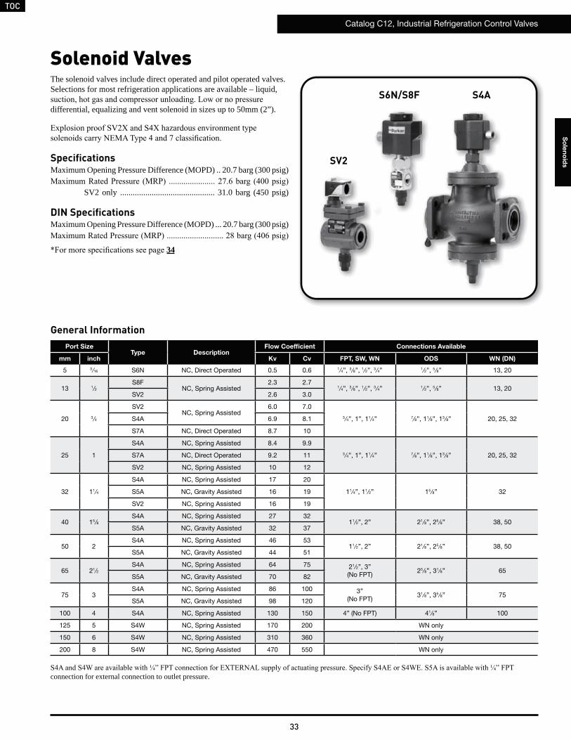
TOC
Catalog C12, Industrial Refrigeration Control Valves
33
So
len
oid
s
Solenoid ValvesThe solenoid valves include direct operated and pilot operated valves. Selections for most refrigeration applications are available – liquid,
differential, equalizing and vent solenoid in sizes up to 50mm (2”).
SpecificationsMaximum Opening Pressure Difference (MOPD) .. 20.7 barg (300 psig)
SV2 only ............................................. 31.0 barg (450 psig)
DIN SpecificationsMaximum Opening Pressure Difference (MOPD) ... 20.7 barg (300 psig)
34
S6N/S8F S4A
Port SizeType Description
Flow Coefficient Connections Available
mm inch Kv Cv FPT, SW, WN ODS WN (DN)
5 3 ⁄16 S6N NC, Direct Operated 0.5 0.6 1⁄4”, 3 ⁄8”, 1 ⁄2”, 3 ⁄4” 1 ⁄2”, 5 ⁄8” 13, 20
13 1⁄2S8F
NC, Spring Assisted2.3 2.7
1⁄4”, 3 ⁄8”, 1 ⁄2”, 3 ⁄4” 1 ⁄2”, 5 ⁄8” 13, 20SV2 2.6 3.0
20 3 ⁄4
SV2NC, Spring Assisted
6.0 7.0
3 ⁄4”, 1”, 11⁄4” 7⁄8”, 11⁄8”, 13 ⁄8” 20, 25, 32S4A 6.9 8.1
S7A NC, Direct Operated 8.7 10
25 1
S4A NC, Spring Assisted 8.4 9.9
3 ⁄4”, 1”, 11⁄4” 7⁄8”, 11⁄8”, 13 ⁄8” 20, 25, 32S7A NC, Direct Operated 9.2 11
SV2 NC, Spring Assisted 10 12
32 11⁄4
S4A NC, Spring Assisted 17 20
11⁄4”, 11⁄2” 15 ⁄8” 32S5A NC, Gravity Assisted 16 19
SV2 NC, Spring Assisted 16 19
40 15 ⁄8S4A NC, Spring Assisted 27 32
11⁄2”, 2” 21⁄8”, 25 ⁄8” 38, 50S5A NC, Gravity Assisted 32 37
50 2S4A NC, Spring Assisted 46 53
11⁄2”, 2” 21⁄8”, 25 ⁄8” 38, 50S5A NC, Gravity Assisted 44 51
65 21⁄2S4A NC, Spring Assisted 64 75 21⁄2”, 3”
(No FPT)25 ⁄8”, 31⁄8” 65
S5A NC, Gravity Assisted 70 82
75 3S4A NC, Spring Assisted 86 100 3”
(No FPT)31⁄8”, 35 ⁄8” 75
S5A NC, Gravity Assisted 98 120
100 4 S4A NC, Spring Assisted 130 150 4” (No FPT) 41⁄8” 100
125 5 S4W NC, Spring Assisted 170 200 WN only
150 6 S4W NC, Spring Assisted 310 360 WN only
200 8 S4W NC, Spring Assisted 470 550 WN only
connection for external connection to outlet pressure.
SV2
General Information
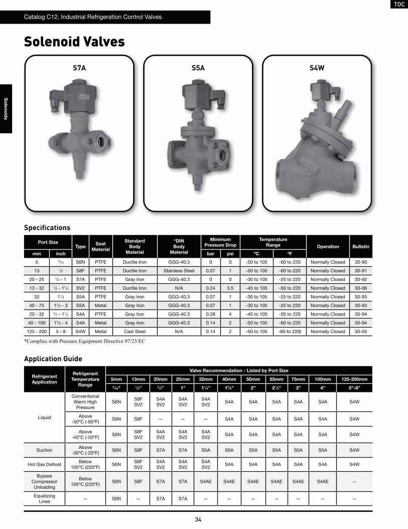
TOC
Catalog C12, Industrial Refrigeration Control Valves
34
So
len
oid
s
Solenoid Valves
Application Guide
Refrigerant
Application
Refrigerant
Temperature
Range
Valve Recommendation - Listed by Port Size
5mm 13mm 20mm 25mm 32mm 40mm 50mm 65mm 75mm 100mm 125-200mm
3⁄16” 1 ⁄2” 3 ⁄4” 1” 11 ⁄4” 15 ⁄8” 2” 21 ⁄2” 3” 4” 5”-8”
Liquid
Conventional Warm High Pressure
S6NS8FSV2
S4ASV2
S4ASV2
S4ASV2
S4A S4A S4A S4A S4A S4W
Above -50ºC (-60ºF)
S6N S8F — — — S4A S4A S4A S4A S4A S4W
Above -45ºC (-50ºF)
S6NS8FSV2
S4ASV2
S4ASV2
S4ASV2
S4A S4A S4A S4A S4A S4W
SuctionAbove
-30ºC (-25ºF)S6N S8F S7A S7A S5A S5A S5A S5A S5A S5A S4W
Hot Gas DefrostBelow
105ºC (220ºF)S6N
S8FSV2
S4ASV2
S4ASV2
S4ASV2
S4A S4A S4A S4A S4A S4W
BypassCompressorUnloading
Below 105ºC (220ºF)
S6N S8F S7A S7A S4AE S4AE S4AE S4AE S4AE S4AE —
EqualizingLines
— S6N — S7A S7A — — — — — — —
Specifications
S4WS5AS7A
Port SizeType
Seat
Material
Standard
Body
Material
*DIN
Body
Material
Minimum
Pressure Drop
Temperature
Range Operation Bulletin
mm inch bar psi ºC ºF
5 3 ⁄16 S6N PTFE Ductile Iron GGG-40.3 0 0 -50 to 105 -60 to 220 Normally Closed 30-90
13 1⁄2 S8F PTFE Ductile Iron Stainless Steel 0.07 1 -50 to 105 -60 to 220 Normally Closed 30-91
20 - 25 3 ⁄4 - 1 S7A PTFE Gray Iron GGG-40.3 0 0 -30 to 105 -25 to 220 Normally Closed 30-92
13 - 32 1⁄2 - 11⁄4 SV2 PTFE Ductile Iron N/A 0.24 3.5 -45 to 105 -50 to 220 Normally Closed 30-06
32 11⁄4 S5A PTFE Gray Iron GGG-40.3 0.07 1 -30 to 105 -25 to 220 Normally Closed 30-93
40 - 75 15 ⁄8 - 3 S5A Metal Gray Iron GGG-40.3 0.07 1 -30 to 105 -25 to 220 Normally Closed 30-93
20 - 32 3 ⁄4 - 11⁄4 S4A PTFE Gray Iron GGG-40.3 0.28 4 -45 to 105 -50 to 220 Normally Closed 30-94
40 - 100 15 ⁄8 - 4 S4A Metal Gray Iron GGG-40.3 0.14 2 -50 to 105 -60 to 220 Normally Closed 30-94
125 - 200 5 - 8 S4W Metal Cast Steel N/A 0.14 2 -50 to 105 -60 to 220) Normally Closed 30-05
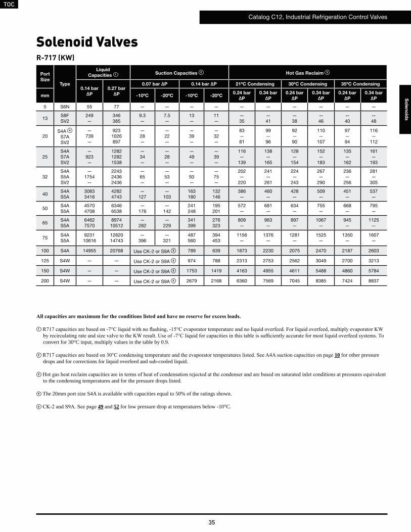
TOC
Catalog C12, Industrial Refrigeration Control Valves
35
So
len
oid
s
Solenoid Valves
Port
SizeType
Liquid
Capacities 1 Suction Capacities 2 Hot Gas Reclaim 3
0.14 bar
ΔP
0.27 bar
ΔP
0.07 bar ΔP 0.14 bar ΔP 21ºC Condensing 30ºC Condensing 35ºC Condensing
mm -10ºC -20ºC -10ºC -20ºC0.24 bar
ΔP
0.34 bar
ΔP
0.24 bar
ΔP
0.34 bar
ΔP
0.24 bar
ΔP
0.34 bar
ΔP
5 S6N 55 77 — — — — — — — — — —
13S8FSV2
249—
346385
9.3—
7.5—
13—
11—
—35
—41
—38
—46
—40
—48
20S4A 4
S7ASV2
—739—
9231026897
—28—
—22—
—39—
—32—
83—81
99—96
92—90
110—
107
97—94
116—
112
25S4AS7ASV2
—923—
128212821538
—34—
—28—
—49—
—39—
116—
139
138—
165
128—
154
152—
183
135—
162
161—
193
32S4AS5ASV2
—1754
—
224324362436
—65—
—53—
—93—
—75—
202—
220
241—
261
224—
243
267—
290
236—
256
281—
305
40S4AS5A
30833416
42824743
—127
—103
163180
132146
386—
460—
428—
509—
451—
537—
50S4AS5A
45704708
63466538
—176
—142
241248
195201
572—
681—
634—
755—
668—
795—
65S4AS5A
64627570
897410512
—282
—229
341399
276323
809—
963—
897—
1067—
945—
1125—
75S4AS5A
923110616
1282014743
—396
—321
487560
394453
1156—
1376—
1281—
1525—
1350—
1607—
100 S4A 14955 20768 Use CK-2 or S9A 5 789 639 1873 2230 2075 2470 2187 2603
125 S4W — — Use CK-2 or S9A 5 974 788 2313 2753 2562 3049 2700 3213
150 S4W — — Use CK-2 or S9A 5 1753 1419 4163 4955 4611 5488 4860 5784
200 S4W — — Use CK-2 or S9A 5 2679 2168 6360 7569 7045 8385 7424 8837
1
convert for 30°C input, multiply values in the table by 0.9.
2 10 for other pressure drops and for corrections for liquid overfeed and sub-cooled liquid.
3 to the condensing temperatures and for the pressure drops listed.
4 The 20mm port size S4A is available with capacities equal to 50% of the ratings shown.
5 49 and 52 for low pressure drop at temperatures below -10°C.
R-717 (KW)
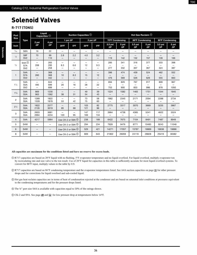
TOC
Catalog C12, Industrial Refrigeration Control Valves
36
So
len
oid
s
Solenoid ValvesR-717 (TONS)
Port
SizeType
Liquid
Capacities 1 Suction Capacities 2 Hot Gas Reclaim 3
2 psi
ΔP
4 psi
ΔP
1 psi ΔP 2 psi ΔP 70ºF Condensing 86ºF Condensing 95ºF Condensing
Inch 20ºF 0ºF 20ºF 0ºF3.5 psi
ΔP
5 psi
ΔP
3.5 psi
ΔP
5 psi
ΔP
3.5 psi
ΔP
5 psi
ΔP
3 ⁄16 S6N 16 22 — — — — — — — — — —
1⁄2S8FSV2
70—
99110
2.8—
2.2—
4.0—
3.2—
—119
—142
—132
—157
—139
—166
3 ⁄4S4A 4
S7ASV2
—208—
265295258
—8.3—
—6.6—
—12—
—9.3—
285—
277
341—
332
316—
307
377—
367
333—
324
398—
387
1S4AS7ASV2
—260—
368368442
—10—
—8.3—
—15—
—12—
396—
476
474—
569
439—
526
524—
629
462—
555
552—
663
11⁄4S4AS5ASV2
—495—
644699699
—20—
—16—
—28—
—22—
694—
753
829—
900
767—
833
917—
996
809—
878
967—
1050
15 ⁄8S4AS5A
869963
12301362
—38
—31
4954
3943
1324—
1582—
1465—
1751—
1544—
1845—
2S4AS5A
12891328
18221878
—53
—42
7375
5860
1962—
2345—
2171—
2594—
2288—
2734—
21⁄2S4AS5A
18222135
25773019
—85
—68
103121
8296
2775—
3317—
3070—
3669—
3235—
3867—
3S4AS5A
26032994
36814234
—120
—95
147169
117134
3964—
4738—
4385—
5241—
4622—
5524—
4 S4A 4217 5964 Use CK-2 or S9A 5 238 189 6422 7675 7104 8491 7487 8949
5 S4W — — Use CK-2 or S9A 5 294 234 7928 9476 8771 10483 9243 11048
6 S4W — — Use CK-2 or S9A 5 529 421 14271 17057 15787 18869 16638 19886
8 S4W — — Use CK-2 or S9A 5 809 643 21802 26059 24119 28828 25419 30382
1
convert for 86°F input, multiply values in the table by 0.9.
2 11 for other pressure drops and for corrections for liquid overfeed and sub-cooled liquid.
3 to the condensing temperatures and for the pressure drops listed.
4 The ¾” port size S4A is available with capacities equal to 50% of the ratings shown.
5 49 and 52 for low pressure drop at temperatures below 14°F.
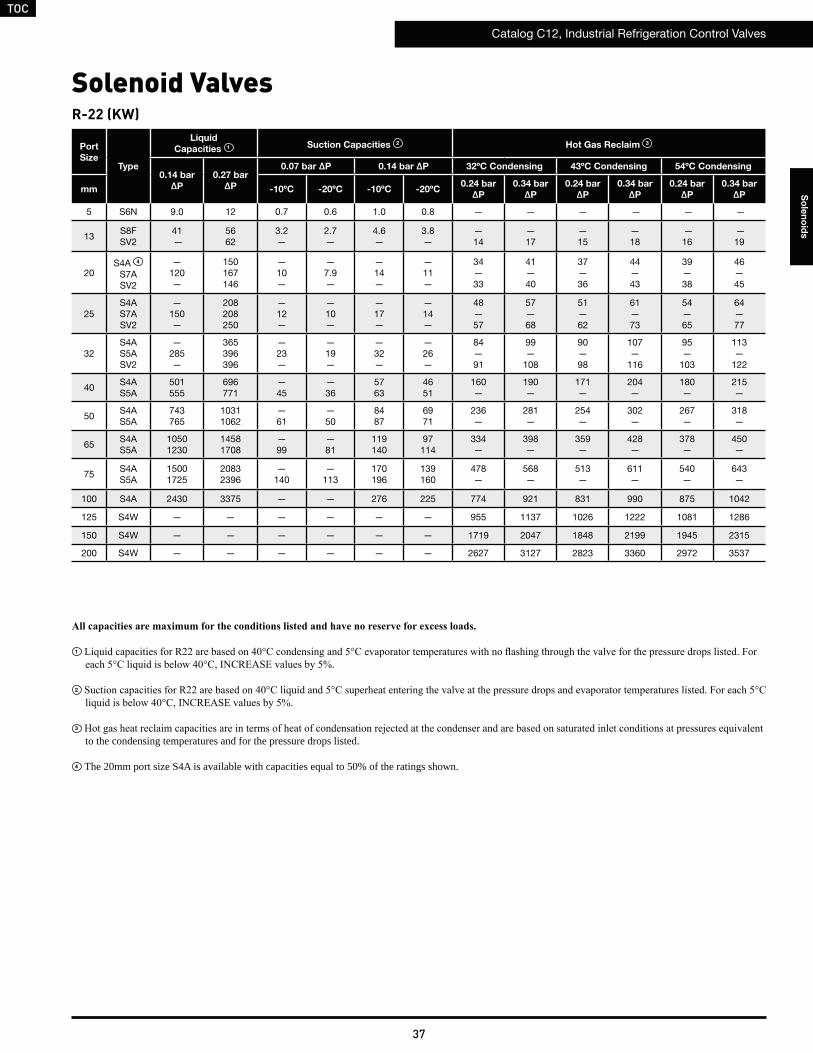
TOC
Catalog C12, Industrial Refrigeration Control Valves
37
So
len
oid
s
Solenoid Valves
Port
SizeType
Liquid
Capacities 1 Suction Capacities 2 Hot Gas Reclaim 3
0.14 bar
ΔP
0.27 bar
ΔP
0.07 bar ΔP 0.14 bar ΔP 32ºC Condensing 43ºC Condensing 54ºC Condensing
mm -10ºC -20ºC -10ºC -20ºC0.24 bar
ΔP
0.34 bar
ΔP
0.24 bar
ΔP
0.34 bar
ΔP
0.24 bar
ΔP
0.34 bar
ΔP
5 S6N 9.0 12 0.7 0.6 1.0 0.8 — — — — — —
13S8FSV2
41 —
5662
3.2—
2.7—
4.6—
3.8—
— 14
— 17
— 15
— 18
—16
—19
20S4A 4
S7ASV2
— 120—
150167146
—10—
—7.9—
—14—
—11—
34—33
41—40
37—36
44—43
39—38
46—45
25S4AS7ASV2
— 150—
208208250
—12—
—10—
—17—
—14—
48—57
57—68
51—62
61—73
54—65
64—77
32S4AS5ASV2
— 285—
365396396
—23—
—19—
—32—
—26—
84—91
99—
108
90—98
107—
116
95—
103
113—
122
40S4AS5A
501555
696771
—45
—36
5763
4651
160—
190—
171—
204—
180—
215—
50S4AS5A
743765
10311062
—61
—50
8487
6971
236—
281—
254—
302—
267—
318—
65S4AS5A
10501230
14581708
—99
—81
119140
97114
334—
398—
359—
428—
378—
450—
75S4AS5A
15001725
20832396
—140
—113
170196
139160
478—
568—
513—
611—
540—
643—
100 S4A 2430 3375 — — 276 225 774 921 831 990 875 1042
125 S4W — — — — — — 955 1137 1026 1222 1081 1286
150 S4W — — — — — — 1719 2047 1848 2199 1945 2315
200 S4W — — — — — — 2627 3127 2823 3360 2972 3537
R-22 (KW)
1
2
3 to the condensing temperatures and for the pressure drops listed.
4 The 20mm port size S4A is available with capacities equal to 50% of the ratings shown.

TOC
Catalog C12, Industrial Refrigeration Control Valves
38
So
len
oid
s
Solenoid ValvesR-22 (TONS)
Port
SizeType
Liquid
Capacities 1 Suction Capacities 2 Hot Gas Reclaim 3
2 psi
ΔP
4 psi
ΔP
1 psi ΔP 2 psi ΔP 90ºF Condensing 110ºF Condensing 130ºF Condensing
Inch 20ºF 0ºF 20ºF 0ºF3.5 psi
ΔP
5 psi
ΔP
3.5 psi
ΔP
5 psi
ΔP
3.5 psi
ΔP
5 psi
ΔP
3 ⁄16 S6N 2.6 3.7 0.2 0.2 0.3 0.3 — — — — — —
1⁄2S8FSV2
12 —
1718
1.0—
0.8—
1.4—
1.1—
— 49
— 59
—53
— 63
— 56
— 66
3 ⁄4S4A 4
S7ASV2
— 35—
444943
—3.0—
—2.4—
—4.2—
—3.4—
118—
115
141—
137
127—
123
151—
147
133—
130
159—
155
1S4AS7ASV2
— 43—
616173
—3.7—
—3.0—
—5.2—
—4.2—
164—
197
196—
235
176—
211
210—
252
185—
222
221—
266
11⁄4S4AS5ASV2
— 82—
107116116
—7.0—
—5.6—
—9.9—
—8.0—
287—
311
343—
372
308—
334
368—
400
324—
352
388—
421
15 ⁄8S4AS5A
145160
204227
—14
—11
1719
1416
547—
654—
588—
703—
619—
740—
2S4AS5A
210221
303312
—19
—15
2627
2121
811—
969—
871—
1042—
917—
1096—
21⁄2S4AS5A
303350
429502
—30
—24
3743
2934
1147—
1370—
1232—
1473—
1297—
1550—
3S4AS5A
433498
612704
—43
—34
5260
4248
1638—
1958—
1760—
2104—
1853—
2215—
4 S4A 701 992 — — 85 68 2653 3171 2852 3409 3002 3588
5 S4W — — — — — — 3276 3915 3521 4208 3706 4429
6 S4W — — — — — — 5896 7048 6337 7575 6671 7973
8 S4W — — — — — — 9009 10767 9682 11572 10191 12181
1
2
3 to the condensing temperatures and for the pressure drops listed.
4 The ¾” port size S4A is available with capacities equal to 50% of the ratings shown.
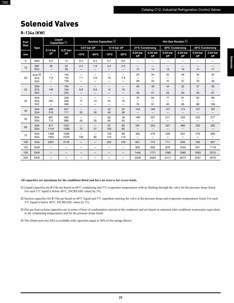
TOC
Catalog C12, Industrial Refrigeration Control Valves
39
So
len
oid
s
Port
SizeType
Liquid
Capacities 1 Suction Capacities 2 Hot Gas Reclaim 3
0.14 bar
ΔP
0.27 bar
ΔP
0.07 bar ΔP 0.14 bar ΔP 21ºC Condensing 30ºC Condensing 35ºC Condensing
mm -10ºC -20ºC -10ºC -20ºC0.24 bar
ΔP
0.34 bar
ΔP
0.24 bar
ΔP
0.34 bar
ΔP
0.24 bar
ΔP
0.34 bar
ΔP
5 S6N 8.4 12 0.5 0.4 0.7 0.6 — — — — — —
13S8FSV2
38 —
5258
2.4—
1.9—
3.4—
2.6—
— 12
— 14
— 13
— 16
— 14
— 17
20S4A 4
S7ASV2
— 112—
140155136
—7.1—
—5.6—
—10—
—7.9—
29—28
34—33
32—31
38—37
34—33
40—39
25S4AS7ASV2
— 140—
194194233
—8.8—
—6.9—
—12—
—10—
40—48
48—57
44—53
52—63
47—56
56—67
32S4AS5ASV2
— 265—
339368368
—17—
—13—
—24—
—19—
70—76
84—91
77—83
91—99
82—89
98—
106
40S4AS5A
466516
647717
—33
—26
4246
3336
134—
160—
147—
174—
157—
187—
50S4AS5A
691712
959988
—45
—35
6264
4950
199—
237—
217—
259—
233—
277—
65S4AS5A
9771144
13571589
—72
—57
87102
6980
281—
335—
307—
366—
329—
392—
75S4AS5A
13961605
19382229
—100
—80
125144
98113
402—
478—
439—
522—
470—
560—
100 S4A 2261 3140 — — 202 159 651 774 711 846 762 907
125 S4W — — — — — — 803 956 878 1045 941 1119
150 S4W — — — — — — 1446 1721 1580 1880 1693 2015
200 S4W — — — — — — 2209 2629 2414 2873 2587 3079
R-134a (KW)
Solenoid Valves
1
2
3 to the condensing temperatures and for the pressure drops listed.
4 The 20mm port size S4A is available with capacities equal to 50% of the ratings shown.
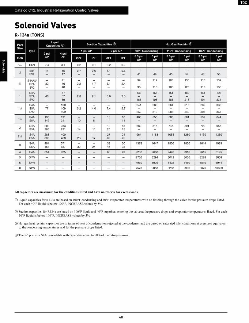
TOC
Catalog C12, Industrial Refrigeration Control Valves
40
So
len
oid
s
R-134a (TONS)
Port
SizeType
Liquid
Capacities 1 Suction Capacities 2 Hot Gas Reclaim 3
2 psi
ΔP
4 psi
ΔP
1 psi ΔP 2 psi ΔP 90ºF Condensing 110ºF Condensing 130ºF Condensing
Inch 20ºF 0ºF 20ºF 0ºF3.5 psi
ΔP
5 psi
ΔP
3.5 psi
ΔP
5 psi
ΔP
3.5 psi
ΔP
5 psi
ΔP
3 ⁄16 S6N 2.4 3.4 0.2 0.1 0.2 0.2 — — — — — —
1⁄2S8FSV2
11—
1517
0.7—
0.6—
1.1—
0.8—
—41
—49
—45
—54
—48
—58
3 ⁄4S4A 4
S7ASV2
—32—
414640
—2.2—
—1.7—
—3.1—
—2.4—
99—96
119—
115
108—
105
130—
126
116—
113
139—
135
1S4AS7ASV2
— 40—
575769
—2.8—
—2.1—
—3.9—
—3.0—
138—
165
165—
198
151—
181
180—
216
161—
194
193—
231
11⁄4S4AS5ASV2
— 77—
100109109
—5.2—
—4.0—
—7.4—
—5.7—
241—
262
288—
313
264—
286
315—
342
282—
307
338—
367
15 ⁄8S4AS5A
135149
191211
—10
—8
1314
1011
460—
550—
503—
601—
539—
644—
2S4AS5A
200206
283291
—14
—11
1920
1515
682—
815—
745—
891—
799—
955—
21⁄2S4AS5A
283330
400468
—23
—17
2732
2125
964—
1153—
1054—
1260—
1130—
1350—
3S4AS5A
404464
571657
—32
—24
3945
3035
1378—
1647—
1506—
1800—
1614—
1929—
4 S4A 654 925 — — 63 49 2232 2668 2440 2916 2615 3125
5 S4W — — — — — — 2756 3294 3012 3600 3228 3858
6 S4W — — — — — — 4960 5929 5422 6480 5810 6944
8 S4W — — — — — — 7578 9058 8283 9900 8876 10609
Solenoid Valves
1
2
3 to the condensing temperatures and for the pressure drops listed.
4 The ¾” port size S4A is available with capacities equal to 50% of the ratings shown.

TOC
Catalog C12, Industrial Refrigeration Control Valves
41
So
len
oid
s
Port
SizeType
Liquid
Capacities 1 Suction Capacities 2 Hot Gas Reclaim 3
0.14 bar
ΔP
0.27 bar
ΔP
0.07 bar ΔP 0.14 bar ΔP 21ºC Condensing 30ºC Condensing 35ºC Condensing
mm -10ºC -20ºC -10ºC -20ºC0.24 bar
ΔP
0.34 bar
ΔP
0.24 bar
ΔP
0.34 bar
ΔP
0.24 bar
ΔP
0.34 bar
ΔP
5 S6N 5.7 7.9 0.6 0.5 0.8 0.7 — — — — — —
13S8FSV2
26—
3640
2.6—
2.1—
3.7—
3.0—
—13
—16
—14
—16
—13
—16
20S4A 4
S7ASV2
— 76—
9510693
—7.8—
—6.2—
—11—
—8.7—
32—31
38—36
33—32
39—38
32—31
38—37
25S4AS7ASV2
— 95 —
132132159
—9.7—
—7.7—
—14—
—11—
44—53
52—63
45—54
54—65
45—53
53—64
32S4AS5ASV2
— 181—
232252252
—19—
—15—
—26—
—21—
77—83
91—99
79—86
94—
103
78—85
93—
101
40S4AS5A
318353
442490
—36
—29
4651
3740
146—
174—
151—
180—
149—
177—
50S4AS5A
472486
655675
—50
—39
6870
5456
217—
258—
224—
267—
220—
262—
65S4AS5A
667782
9271086
—80
—63
96113
7790
307—
365—
317—
378—
312—
371—
75S4AS5A
9541097
13241523
—110
—89
138158
109126
438—
521—
453—
540—
445—
530—
100 S4A 1545 2145 — — 223 178 710 845 734 874 721 858
125 S4W — — — — — — 876 1043 907 1079 890 1060
150 S4W — — — — — — 1577 1877 1632 1942 1603 1908
200 S4W — — — — — — 2409 2868 2493 2967 2449 2915
R-404a (KW)
Solenoid Valves
1
2
3 to the condensing temperatures and for the pressure drops listed.
4 The 20mm port size S4A is available with capacities equal to 50% of the ratings shown.
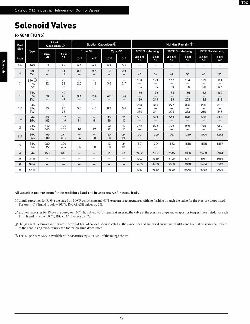
TOC
Catalog C12, Industrial Refrigeration Control Valves
42
So
len
oid
s
R-404a (TONS)
Port
SizeType
Liquid
Capacities 1 Suction Capacities 2 Hot Gas Reclaim 3
2 psi
ΔP
4 psi
ΔP
1 psi ΔP 2 psi ΔP 90ºF Condensing 110ºF Condensing 130ºF Condensing
Inch 20ºF 0ºF 20ºF 0ºF3.5 psi
ΔP
5 psi
ΔP
3.5 psi
ΔP
5 psi
ΔP
3.5 psi
ΔP
5 psi
ΔP
3 ⁄16 S6N 1.7 2.4 0.2 0.1 0.3 0.2 — — — — — —
1⁄2S8FSV2
7.6—
1112
0.8—
0.6—
1.2—
0.9—
—45
—54
—47
—56
—46
—55
3 ⁄4S4A 4
S7ASV2
— 22—
283228
—2.5—
—1.9—
—3.5—
—2.7—
108—
105
129—
126
112—
109
134—
130
109—
106
131—
127
1S4AS7ASV2
— 28—
404047
—3.1—
—2.4—
—4.3—
—3.4—
150—
180
179—
215
155—
186
186—
223
152—
182
182—
218
11⁄4S4AS5ASV2
— 53—
697575
—5.8—
—4.5—
—8.3—
—6.4—
263—
285
314—
341
272—
295
325—
353
266—
289
318—
345
15 ⁄8S4AS5A
93103
132146
—11
—9
1516
1113
501—
599—
519—
620—
508—
607—
2S4AS5A
140143
196202
—16
—12
2222
1717
743—
888—
769—
919—
753—
900—
21⁄2S4AS5A
196230
277324
—25
—20
3036
2428
1051—
1256—
1087—
1299—
1064—
1272—
3S4AS5A
280322
396455
—35
—28
4350
3439
1501—
1794—
1553—
1856—
1520—
1817—
4 S4A 453 641 — — 71 55 2432 2907 2515 3006 2463 2944
5 S4W — — — — — — 3003 3589 3105 3711 3041 3635
6 S4W — — — — — — 5405 6460 5589 6680 5474 6542
8 S4W — — — — — — 8257 9869 8539 10206 8363 9995
Solenoid Valves
1
2
3 to the condensing temperatures and for the pressure drops listed.
4 The ¾” port size S4A is available with capacities equal to 50% of the ratings shown.
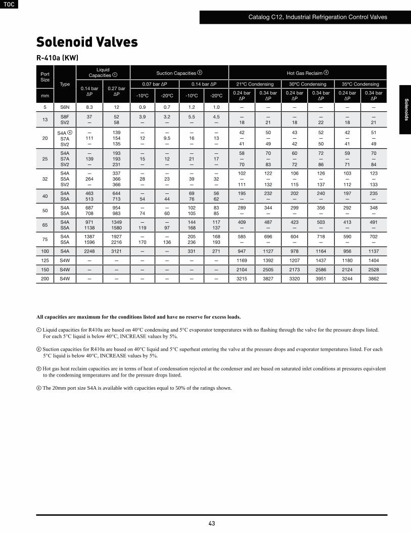
TOC
Catalog C12, Industrial Refrigeration Control Valves
43
So
len
oid
s
Port Size
Type
LiquidCapacities 1 Suction Capacities 2 Hot Gas Reclaim 3
0.14 barΔP
0.27 barΔP
0.07 bar ΔP 0.14 bar ΔP 21ºC Condensing 30ºC Condensing 35ºC Condensing
mm -10ºC -20ºC -10ºC -20ºC0.24 bar
ΔP0.34 bar
ΔP0.24 bar
ΔP0.34 bar
ΔP0.24 bar
ΔP0.34 bar
ΔP
5 S6N 8.3 12 0.9 0.7 1.2 1.0 — — — — — —
13S8FSV2
37—
5258
3.9—
3.2—
5.5—
4.5—
—18
—21
—18
—22
—18
—21
20S4A 4
S7ASV2
— 111—
139154135
—12—
—9.5—
—16—
—13—
42—41
50—49
43—42
52—50
42—41
51—49
25S4AS7ASV2
— 139—
193193231
—15—
—12—
—21—
—17—
58—70
70—83
60—72
72—86
59—71
70—84
32S4AS5ASV2
— 264—
337366366
—28—
—23—
—39—
—32—
102—
111
122—
132
106—
115
126—
137
103—
112
123—
133
40S4AS5A
463513
644713
—54
—44
6976
5662
195—
232—
202—
240—
197—
235—
50S4AS5A
687708
954983
—74
—60
102105
8385
289—
344—
299—
356—
292—
348—
65S4AS5A
9711138
13491580
—119
—97
144168
117137
409—
487—
423—
503—
413—
491—
75S4AS5A
13871596
19272216
—170
—136
205236
168193
585—
696—
604—
718—
590—
702—
100 S4A 2248 3121 — — 331 271 947 1127 978 1164 956 1137
125 S4W — — — — — — 1169 1392 1207 1437 1180 1404
150 S4W — — — — — — 2104 2505 2173 2586 2124 2528
200 S4W — — — — — — 3215 3827 3320 3951 3244 3862
R-410a (KW)
Solenoid Valves
1
2
3 to the condensing temperatures and for the pressure drops listed.
4 The 20mm port size S4A is available with capacities equal to 50% of the ratings shown.

TOC
Catalog C12, Industrial Refrigeration Control Valves
44
So
len
oid
s
R-410a (TONS)
Port
SizeType
Liquid
Capacities 1 Suction Capacities 2 Hot Gas Reclaim 3
2 psi
ΔP
4 psi
ΔP
1 psi ΔP 2 psi ΔP 90ºF Condensing 110ºF Condensing 130ºF Condensing
Inch 20ºF 0ºF 20ºF 0ºF3.5 psi
ΔP
5 psi
ΔP
3.5 psi
ΔP
5 psi
ΔP
3.5 psi
ΔP
5 psi
ΔP
3 ⁄16 S6N 2.4 3.4 0.3 0.2 0.4 0.3 — — — — — —
1⁄2S8FSV2
11—
1517
1.2—
1.0—
1.7—
1.4—
—60
—72
—62
—74
—60
—72
3 ⁄4S4A 4
S7ASV2
— 32—
414640
—3.6—
—2.9—
—5.1—
—4.1—
144—
140
172—
168
149—
145
178—
173
145—
141
173—
168
1S4AS7ASV2
— 40—
575769
—4.5—
—3.6—
—6.4—
—5.1—
200—
240
239—
287
207—
248
247—
296
201—
242
241—
289
11⁄4S4AS5ASV2
— 77—
100109109
—8.5—
—6.9—
—12—
—9.7—
351—
381
419—
455
362—
393
432—
469
352—
383
421—
457
15 ⁄8S4AS5A
135150
191212
—17
—13
2124
1719
669—
800—
690—
825—
673—
804—
2S4AS5A
200206
283292
—23
—18
3132
2526
992—
1185—
1023—
1223—
997—
1191—
21⁄2S4AS5A
283330
400469
—37
—30
4452
3642
1402—
1676—
1447—
1730—
1410—
1685—
3S4AS5A
404465
572658
—52
—41
6473
5159
2003—
2395—
2067—
2471—
2014—
2407—
4 S4A 655 927 — — 102 82 3246 3879 3349 4003 3262 3899
5 S4W — — — — — — 4007 4789 4134 4942 4028 4814
6 S4W — — — — — — 7212 8621 7442 8895 7250 8665
8 S4W — — — — — — 11019 13170 11370 13589 11076 13238
Solenoid Valves
1
2
3 to the condensing temperatures and for the pressure drops listed.
4 The ¾” port size S4A is available with capacities equal to 50% of the ratings shown.

TOC
Catalog C12, Industrial Refrigeration Control Valves
45
So
len
oid
s
Port
SizeType
Liquid
Capacities 1 Suction Capacities 2 Hot Gas Reclaim 3
0.14 bar
ΔP
0.27 bar
ΔP
0.07 bar ΔP 0.14 bar ΔP 21ºC Condensing 30ºC Condensing 35ºC Condensing
mm -10ºC -20ºC -10ºC -20ºC0.24 bar
ΔP
0.34 bar
ΔP
0.24 bar
ΔP
0.34 bar
ΔP
0.24 bar
ΔP
0.34 bar
ΔP
5 S6N 5.5 7.7 0.6 0.5 0.8 0.7 — — — — — —
13S8FSV2
25—
3538
2.6—
2.1—
3.7—
2.9—
—13
—16
—13
—16
—13
—16
20S4A 4
S7ASV2
— 74—
9210390
—7.8—
—6.2—
—11—
—8.7—
31—31
37—36
32—31
39—37
31—31
37—36
25S4AS7ASV2
— 92—
128128154
—10—
—7.7—
—14—
—11—
44—52
52—62
45—54
54—64
44—52
52—62
32S4AS5ASV2
— 175—
224243243
—18—
—15—
—26—
—21—
76—83
91—99
79—85
94—
102
76—83
91—99
40S4AS5A
308341
428474
—36
—29
4651
3640
146—
174—
150—
179—
146—
174—
50S4AS5A
457471
634654
—49
—39
6870
5456
216—
257—
223—
265—
216—
258—
65S4AS5A
646757
8971051
—80
—63
96113
7689
306—
364—
315—
375—
306—
364—
75S4AS5A
9231061
12811474
—110
—89
137158
109125
437—
520—
450—
535—
437—
520—
100 S4A 1495 2076 — — 222 176 708 842 728 867 708 843
125 S4W — — — — — — 874 1040 899 1070 874 1040
150 S4W — — — — — — 1572 1872 1619 1927 1573 1873
200 S4W — — — — — — 2402 2859 2473 2944 2404 2861
R-507a (KW)
Solenoid Valves
1
2
3 to the condensing temperatures and for the pressure drops listed.
4 The 20mm port size S4A is available with capacities equal to 50% of the ratings shown.
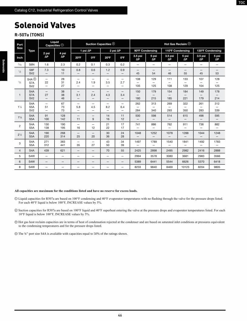
TOC
Catalog C12, Industrial Refrigeration Control Valves
46
So
len
oid
s
R-507a (TONS)
Port
SizeType
Liquid
Capacities 1 Suction Capacities 2 Hot Gas Reclaim 3
2 psi
ΔP
4 psi
ΔP
1 psi ΔP 2 psi ΔP 90ºF Condensing 110ºF Condensing 130ºF Condensing
Inch 20ºF 0ºF 20ºF 0ºF3.5 psi
ΔP
5 psi
ΔP
3.5 psi
ΔP
5 psi
ΔP
3.5 psi
ΔP
5 psi
ΔP
3 ⁄16 S6N 1.6 2.3 0.2 0.1 0.3 0.2 — — — — — —
1⁄2S8FSV2
7.3—
1011
0.8—
0.6—
1.2—
0.9—
—45
—54
—46
—55
—45
—53
3 ⁄4S4A 4
S7ASV2
— 22—
283127
—2.4—
—1.9—
—3.5—
—2.7—
108—
105
129—
125
111—
108
133—
129
107—
104
128—
125
1S4AS7ASV2
— 27—
383846
—3.1—
—2.4—
—4.3—
—3.4—
150—
180
179—
215
154—
185
184—
221
149—
179
178—
214
11⁄4S4AS5ASV2
— 51—
677373
—5.8—
—4.5—
—8.2—
—6.4—
262—
284
313—
340
269—
293
322—
350
261—
283
312—
339
15 ⁄8S4AS5A
91100
128142
—11
—9
1416
1112
500—
598—
514—
615—
498—
595—
2S4AS5A
130138
190195
—16
—12
2122
1717
741—
886—
762—
911—
738—
882—
21⁄2S4AS5A
190220
268314
—25
—20
3036
2428
1048—
1252—
1078—
1288—
1044—
1248—
3S4AS5A
271312
383441
—35
—27
4350
3439
1497—
1789—
1540—
1841—
1492—
1783—
4 S4A 439 621 — — 70 55 2425 2898 2495 2982 2416 2888
5 S4W — — — — — — 2994 3578 3080 3681 2983 3566
6 S4W — — — — — — 5389 6441 5544 6626 5370 6418
8 S4W — — — — — — 8233 9840 8469 10123 8204 9805
Solenoid Valves
1
2
3 to the condensing temperatures and for the pressure drops listed.
4 The ¾” port size S4A is available with capacities equal to 50% of the ratings shown.
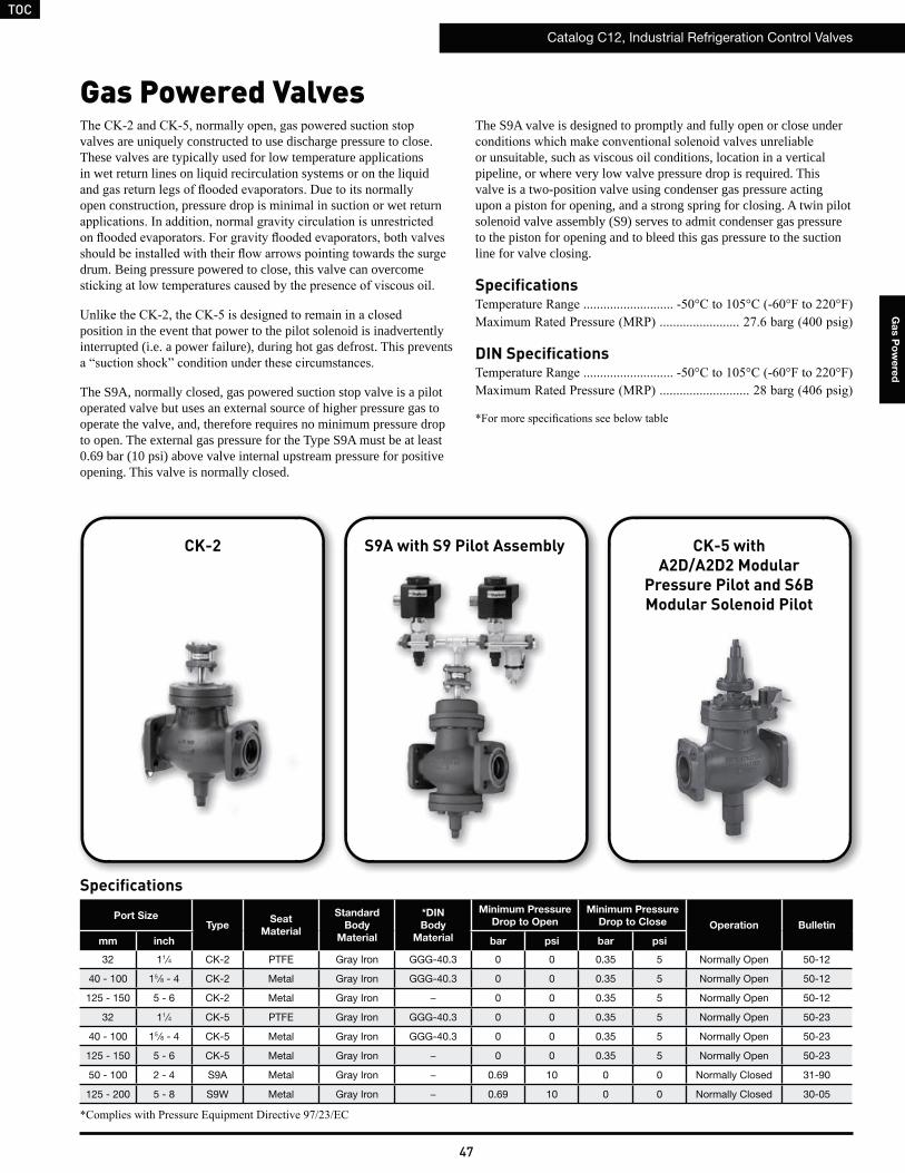
TOC
Catalog C12, Industrial Refrigeration Control Valves
47
Ga
s P
ow
ere
d
Gas Powered Valves
Specifications
valves are uniquely constructed to use discharge pressure to close. These valves are typically used for low temperature applications in wet return lines on liquid recirculation systems or on the liquid
open construction, pressure drop is minimal in suction or wet return
drum. Being pressure powered to close, this valve can overcome
position in the event that power to the pilot solenoid is inadvertently interrupted (i.e. a power failure), during hot gas defrost. This prevents
The S9A, normally closed, gas powered suction stop valve is a pilot operated valve but uses an external source of higher pressure gas to operate the valve, and, therefore requires no minimum pressure drop to open. The external gas pressure for the Type S9A must be at least 0.69 bar (10 psi) above valve internal upstream pressure for positive opening. This valve is normally closed.
CK-2 S9A with S9 Pilot Assembly CK-5 withA2D/A2D2 Modular
Pressure Pilot and S6B Modular Solenoid Pilot
The S9A valve is designed to promptly and fully open or close under
or unsuitable, such as viscous oil conditions, location in a vertical pipeline, or where very low valve pressure drop is required. This valve is a two-position valve using condenser gas pressure acting upon a piston for opening, and a strong spring for closing. A twin pilot solenoid valve assembly (S9) serves to admit condenser gas pressure to the piston for opening and to bleed this gas pressure to the suction line for valve closing.
Specifications
DIN Specifications
Port SizeType
Seat
Material
Standard
Body
Material
*DIN
Body
Material
Minimum Pressure
Drop to Open
Minimum Pressure
Drop to Close Operation Bulletin
mm inch bar psi bar psi
32 11⁄4 CK-2 PTFE Gray Iron GGG-40.3 0 0 0.35 5 Normally Open 50-12
40 - 100 15 ⁄8 - 4 CK-2 Metal Gray Iron GGG-40.3 0 0 0.35 5 Normally Open 50-12
125 - 150 5 - 6 CK-2 Metal Gray Iron − 0 0 0.35 5 Normally Open 50-12
32 11⁄4 CK-5 PTFE Gray Iron GGG-40.3 0 0 0.35 5 Normally Open 50-23
40 - 100 15 ⁄8 - 4 CK-5 Metal Gray Iron GGG-40.3 0 0 0.35 5 Normally Open 50-23
125 - 150 5 - 6 CK-5 Metal Gray Iron − 0 0 0.35 5 Normally Open 50-23
50 - 100 2 - 4 S9A Metal Gray Iron − 0.69 10 0 0 Normally Closed 31-90
125 - 200 5 - 8 S9W Metal Gray Iron − 0.69 10 0 0 Normally Closed 30-05
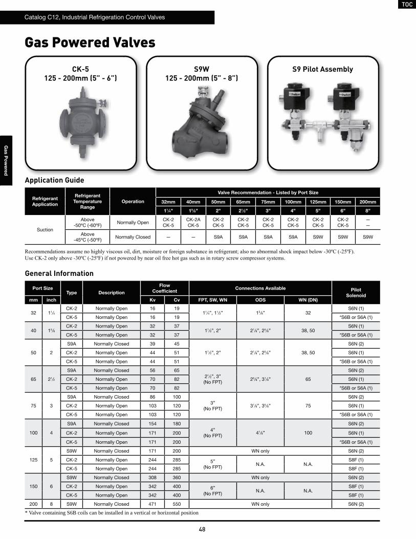
TOC
Catalog C12, Industrial Refrigeration Control Valves
48
Ga
s P
ow
ere
d
Port SizeType Description
Flow
CoefficientConnections Available Pilot
Solenoidmm inch Kv Cv FPT, SW, WN ODS WN (DN)
32 11⁄4CK-2 Normally Open 16 19
11⁄4”, 11⁄2” 15 ⁄8” 32S6N (1)
CK-5 Normally Open 16 19 *S6B or S6A (1)
40 15 ⁄8CK-2 Normally Open 32 37
11⁄2”, 2” 21⁄8”, 25 ⁄8” 38, 50S6N (1)
CK-5 Normally Open 32 37 *S6B or S6A (1)
50 2
S9A Normally Closed 39 45
11⁄2”, 2” 21⁄8”, 25 ⁄8” 38, 50
S6N (2)
CK-2 Normally Open 44 51 S6N (1)
CK-5 Normally Open 44 51 *S6B or S6A (1)
65 21⁄2
S9A Normally Closed 56 6521⁄2”, 3”(No FPT)
25 ⁄8”, 31⁄8” 65
S6N (2)
CK-2 Normally Open 70 82 S6N (1)
CK-5 Normally Open 70 82 *S6B or S6A (1)
75 3
S9A Normally Closed 86 1003”
(No FPT)31⁄8”, 35 ⁄8” 75
S6N (2)
CK-2 Normally Open 103 120 S6N (1)
CK-5 Normally Open 103 120 *S6B or S6A (1)
100 4
S9A Normally Closed 154 1804”
(No FPT)41⁄8” 100
S6N (2)
CK-2 Normally Open 171 200 S6N (1)
CK-5 Normally Open 171 200 *S6B or S6A (1)
125 5
S9W Normally Closed 171 200 WN only S6N (2)
CK-2 Normally Open 244 285 5”(No FPT)
N.A. N.A.S8F (1)
CK-5 Normally Open 244 285 S8F (1)
150 6
S9W Normally Closed 308 360 WN only S6N (2)
CK-2 Normally Open 342 400 6”(No FPT)
N.A. N.A.S8F (1)
CK-5 Normally Open 342 400 S8F (1)
200 8 S9W Normally Closed 471 550 WN only S6N (2)
Gas Powered Valves
General Information
Application Guide
Refrigerant
Application
Refrigerant
Temperature
Range
Operation
Valve Recommendation - Listed by Port Size
32mm 40mm 50mm 65mm 75mm 100mm 125mm 150mm 200mm
11⁄4” 15 ⁄8” 2” 21 ⁄2” 3” 4” 5” 6” 8”
Suction
Above -50ºC (-60ºF)
Normally OpenCK-2CK-5
CK-2ACK-5
CK-2CK-5
CK-2CK-5
CK-2CK-5
CK-2CK-5
CK-2CK-5
CK-2CK-5
——
Above -45ºC (-50ºF)
Normally Closed — — S9A S9A S9A S9A S9W S9W S9W
S9W125 - 200mm (5” - 8”)
S9 Pilot Assembly
* Valve containing S6B coils can be installed in a vertical or horizontal position
CK-5 125 - 200mm (5” - 6”)
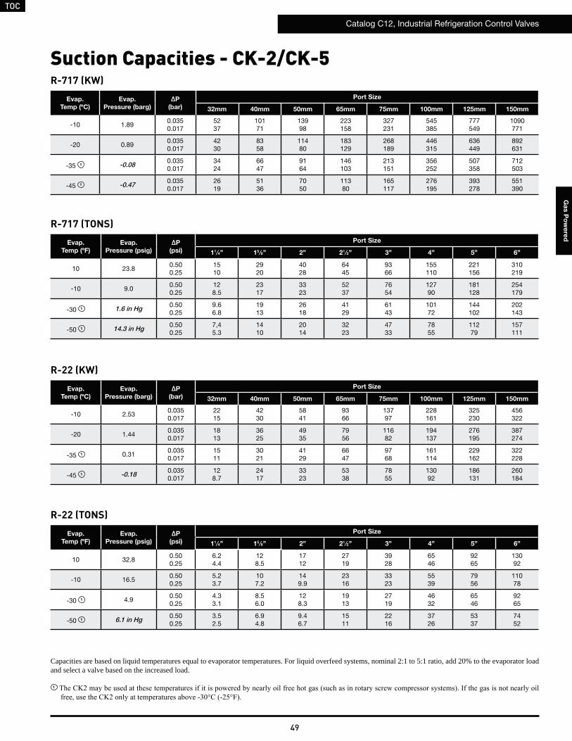
TOC
Catalog C12, Industrial Refrigeration Control Valves
49
Ga
s P
ow
ere
d
Suction Capacities - CK-2/CK-5R-717 (KW)
R-717 (TONS)
Evap.
Temp (ºC)
Evap.
Pressure (barg)
ΔP
(bar)
Port Size
32mm 40mm 50mm 65mm 75mm 100mm 125mm 150mm
-10 1.890.0350.017
5237
10171
13998
223158
327231
545385
777549
1090771
-20 0.890.0350.017
4230
8358
11480
183129
268189
446315
636449
892631
-35 1 -0.08 0.0350.017
3424
6647
9164
146103
213151
356252
507358
712503
-45 1 -0.47 0.0350.017
2619
5136
7050
11380
165117
276195
393278
551390
Evap.
Temp (ºF)
Evap.
Pressure (psig)
ΔP
(psi)
Port Size
11⁄4” 15 ⁄8” 2” 21 ⁄2” 3” 4” 5” 6”
10 23.80.500.25
1510
2920
4028
6445
9366
155110
221156
310219
-10 9.00.500.25
128.5
2317
3323
5237
7654
12790
181128
254179
-30 1 1.6 in Hg 0.500.25
9.66.8
1913
2618
4129
6143
10172
144102
202143
-50 1 14.3 in Hg 0.500.25
7,45.3
1410
2014
3223
4733
7855
11279
157111
Capacities are based on liquid temperatures equal to evaporator temperatures. For liquid overfeed systems, nominal 2:1 to 5:1 ratio, add 20% to the evaporator load and select a valve based on the increased load.
1
R-22 (KW)
R-22 (TONS)
Evap.
Temp (ºC)
Evap.
Pressure (barg)
ΔP
(bar)
Port Size
32mm 40mm 50mm 65mm 75mm 100mm 125mm 150mm
-10 2.530.0350.017
2215
4230
5841
9366
13797
228161
325230
456322
-20 1.440.0350.017
1813
3625
4935
7956
11682
194137
276195
387274
-35 1 0.310.0350.017
1511
3021
4129
6647
9768
161114
229162
322228
-45 1 -0.18 0.0350.017
128.7
2417
3323
5338
7855
13092
186131
260184
Evap.
Temp (ºF)
Evap.
Pressure (psig)
ΔP
(psi)
Port Size
11⁄4” 15 ⁄8” 2” 21 ⁄2” 3” 4” 5” 6”
10 32.80.500.25
6.24.4
128.5
1712
2719
3928
6546
9265
13092
-10 16.50.500.25
5.23.7
107.2
149.9
2316
3323
5539
7956
11078
-30 1 4.90.500.25
4.33.1
8.56.0
128.3
1913
2719
4632
6546
9265
-50 1 6.1 in Hg 0.500.25
3.52.5
6.94.8
9.46.7
1511
2216
3726
5337
7452
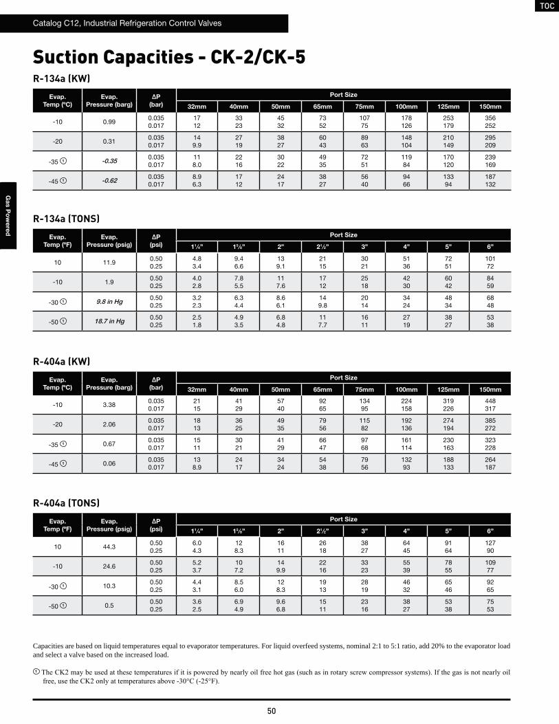
TOC
Catalog C12, Industrial Refrigeration Control Valves
50
Ga
s P
ow
ere
d
Suction Capacities - CK-2/CK-5R-134a (KW)
R-134a (TONS)
Evap.
Temp (ºC)
Evap.
Pressure (barg)
ΔP
(bar)
Port Size
32mm 40mm 50mm 65mm 75mm 100mm 125mm 150mm
-10 0.990.0350.017
1712
3323
4532
7352
10775
178126
253179
356252
-20 0.310.0350.017
149.9
2719
3827
6043
8963
148104
210149
295209
-35 1 -0.35 0.0350.017
118.0
2216
3022
4935
7251
11984
170120
239169
-45 1 -0.62 0.0350.017
8.96.3
1712
2417
3827
5640
9466
13394
187132
Evap.
Temp (ºF)
Evap.
Pressure (psig)
ΔP
(psi)
Port Size
11⁄4” 15 ⁄8” 2” 21 ⁄2” 3” 4” 5” 6”
10 11.90.500.25
4.83.4
9.46.6
139.1
2115
3021
5136
7251
10172
-10 1.90.500.25
4.02.8
7.85.5
117.6
1712
2518
4230
6042
8459
-30 1 9.8 in Hg 0.500.25
3.22.3
6.34.4
8.66.1
149.8
2014
3424
4834
6848
-50 1 18.7 in Hg 0.500.25
2.51.8
4.93.5
6.84.8
117.7
1611
2719
3827
5338
Capacities are based on liquid temperatures equal to evaporator temperatures. For liquid overfeed systems, nominal 2:1 to 5:1 ratio, add 20% to the evaporator load and select a valve based on the increased load.
1
R-404a (KW)
R-404a (TONS)
Evap.
Temp (ºC)
Evap.
Pressure (barg)
ΔP
(bar)
Port Size
32mm 40mm 50mm 65mm 75mm 100mm 125mm 150mm
-10 3.380.0350.017
2115
4129
5740
9265
13495
224158
319226
448317
-20 2.060.0350.017
1813
3625
4935
7956
11582
192136
274194
385272
-35 1 0.670.0350.017
1511
3021
4129
6647
9768
161114
230163
323228
-45 1 0.060.0350.017
138.9
2417
3424
5438
7956
13293
188133
264187
Evap.
Temp (ºF)
Evap.
Pressure (psig)
ΔP
(psi)
Port Size
11⁄4” 15 ⁄8” 2” 21 ⁄2” 3” 4” 5” 6”
10 44.30.500.25
6.04.3
128.3
1611
2618
3827
6445
9164
12790
-10 24.60.500.25
5.23.7
107.2
149.9
2216
3323
5539
7855
10977
-30 1 10.30.500.25
4.43.1
8.56.0
128.3
1913
2819
4632
6546
9265
-50 1 0.50.500.25
3.62.5
6.94.9
9.66.8
1511
2316
3827
5338
7553
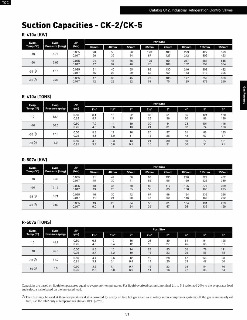
TOC
Catalog C12, Industrial Refrigeration Control Valves
51
Ga
s P
ow
ere
d
Suction Capacities - CK-2/CK-5R-410a (KW)
R-410a (TONS)
Evap.
Temp (ºC)
Evap.
Pressure (barg)
ΔP
(bar)
Port Size
32mm 40mm 50mm 65mm 75mm 100mm 125mm 150mm
-10 4.730.0350.017
2820
5539
7654
12387
180127
299212
427302
599423
-20 2.990.0350.017
2417
4834
6646
10575
154109
257182
367259
515364
-35 1 1.180.0350.017
2115
4028
5539
8963
13092
216153
308218
432306
-45 1 0.380.0350.017
1712
3323
4532
7251
10675
177125
252178
353250
Evap.
Temp (ºF)
Evap.
Pressure (psig)
ΔP
(psi)
Port Size
11⁄4” 15 ⁄8” 2” 21 ⁄2” 3” 4” 5” 6”
10 62.40.500.25
8.15.7
1611
2215
3525
5136
8560
12186
170120
-10 36.50.500.25
7.04.9
149.6
1913
3021
4431
7352
10474
146103
-30 1 17.80.500.25
5.84.1
118.0
1611
2518
3726
6143
8862
12387
-50 1 5.00.500.25
4.83.4
9.36.6
139.1
2115
3021
5036
7251
10171
Capacities are based on liquid temperatures equal to evaporator temperatures. For liquid overfeed systems, nominal 2:1 to 5:1 ratio, add 20% to the evaporator load and select a valve based on the increased load.
1
R-507a (KW)
R-507a (TONS)
Evap.
Temp (ºC)
Evap.
Pressure (barg)
ΔP
(bar)
Port Size
32mm 40mm 50mm 65mm 75mm 100mm 125mm 150mm
-10 3.480.0350.017
2115
4230
5841
9365
13596
226160
322228
452319
-20 2.130.0350.017
1813
3625
5035
8056
11783
195138
277196
389275
-35 1 0.710.0350.017
1611
3021
4230
6747
9869
164116
233165
328232
-45 1 0.090.0350.017
139.0
2518
3424
5539
8157
13495
191135
269190
Evap.
Temp (ºF)
Evap.
Pressure (psig)
ΔP
(psi)
Port Size
11⁄4” 15 ⁄8” 2” 21 ⁄2” 3” 4” 5” 6”
10 45.70.500.25
6.14.3
128.4
1612
2619
3927
6445
9165
12891
-10 25.50.500.25
5.33.7
107.2
1410
2316
3323
5539
7956
11178
-30 1 11.00.500.25
4.43.1
8.66.1
128.4
1914
2820
4733
6647
9366
-50 1 3.00.500.25
3.62.6
7.15.0
9.76.9
1611
2316
3827
5438
7654
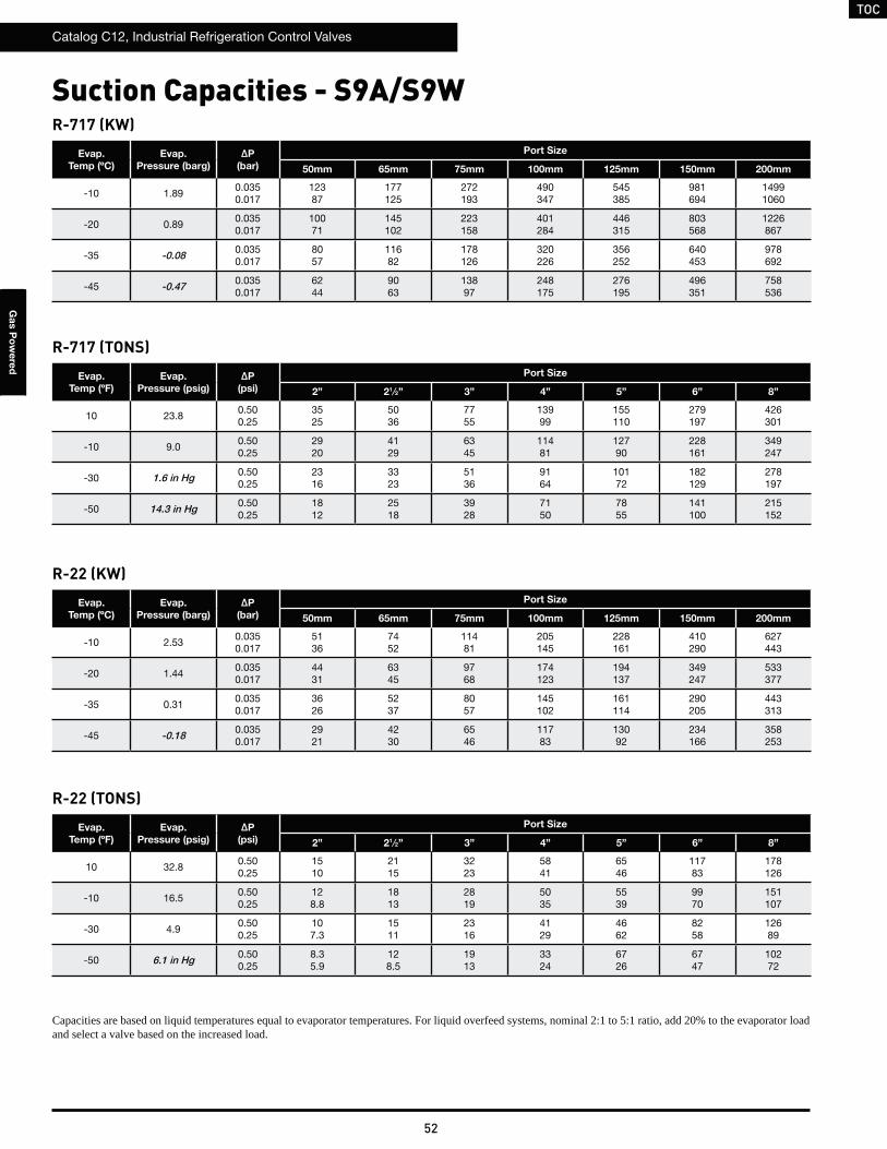
TOC
Catalog C12, Industrial Refrigeration Control Valves
52
Ga
s P
ow
ere
d
Suction Capacities - S9A/S9WR-717 (KW)
R-717 (TONS)
Evap.
Temp (ºC)
Evap.
Pressure (barg)
ΔP
(bar)
Port Size
50mm 65mm 75mm 100mm 125mm 150mm 200mm
-10 1.890.0350.017
12387
177125
272193
490347
545385
981694
14991060
-20 0.890.0350.017
10071
145102
223158
401284
446315
803568
1226867
-35 -0.08 0.0350.017
8057
11682
178126
320226
356252
640453
978692
-45 -0.47 0.0350.017
6244
9063
13897
248175
276195
496351
758536
Evap.
Temp (ºF)
Evap.
Pressure (psig)
ΔP
(psi)
Port Size
2” 21⁄2” 3” 4” 5” 6” 8”
10 23.80.500.25
3525
5036
7755
13999
155110
279197
426301
-10 9.00.500.25
2920
4129
6345
11481
12790
228161
349247
-30 1.6 in Hg 0.500.25
2316
3323
5136
9164
10172
182129
278197
-50 14.3 in Hg 0.500.25
1812
2518
3928
7150
7855
141100
215152
R-22 (KW)
R-22 (TONS)
Evap.
Temp (ºC)
Evap.
Pressure (barg)
ΔP
(bar)
Port Size
50mm 65mm 75mm 100mm 125mm 150mm 200mm
-10 2.530.0350.017
5136
7452
11481
205145
228161
410290
627443
-20 1.440.0350.017
4431
6345
9768
174123
194137
349247
533377
-35 0.310.0350.017
3626
5237
8057
145102
161114
290205
443313
-45 -0.18 0.0350.017
2921
4230
6546
11783
13092
234166
358253
Evap.
Temp (ºF)
Evap.
Pressure (psig)
ΔP
(psi)
Port Size
2” 21⁄2” 3” 4” 5” 6” 8”
10 32.80.500.25
1510
2115
3223
5841
6546
11783
178126
-10 16.50.500.25
128.8
1813
2819
5035
5539
9970
151107
-30 4.90.500.25
107.3
1511
2316
4129
4662
8258
12689
-50 6.1 in Hg 0.500.25
8.35.9
128.5
1913
3324
6726
6747
10272
Capacities are based on liquid temperatures equal to evaporator temperatures. For liquid overfeed systems, nominal 2:1 to 5:1 ratio, add 20% to the evaporator load and select a valve based on the increased load.

TOC
Catalog C12, Industrial Refrigeration Control Valves
53
Ga
s P
ow
ere
d
Suction Capacities - S9A/S9WR-134a (KW)
R-134a (TONS)
Evap.
Temp (ºC)
Evap.
Pressure (barg)
ΔP
(bar)
Port Size
50mm 65mm 75mm 100mm 125mm 150mm 200mm
-10 0.990.0350.017
4028
5841
8963
160113
178126
320226
489346
-20 0.310.0350.017
3323
4834
7452
13394
148104
266188
406287
-35 -0.35 0.0350.017
2719
3927
6042
10776
11984
215152
328232
-45 -0.62 0.0350.017
2115
3021
4733
8460
9466
168119
257182
Evap.
Temp (ºF)
Evap.
Pressure (psig)
ΔP
(psi)
Port Size
2” 21⁄2” 3” 4” 5” 6” 8”
10 11.90.500.25
118.0
1612
2518
4632
5136
9164
13998
-10 1.90.500.25
9.46.7
149.6
2115
3827
4230
7653
11582
-30 9.8 in Hg 0.500.25
7.65.4
447.8
1712
3122
3424
6143
9366
-50 18.7 in Hg 0.500.25
6.04.2
8.66.1
139.4
2417
2719
4834
7352
R-404a (KW)
R-404a (TONS)
Evap.
Temp (ºC)
Evap.
Pressure (barg)
ΔP
(bar)
Port Size
50mm 65mm 75mm 100mm 125mm 150mm 200mm
-10 3.380.0350.017
5036
7351
11279
202142
224158
403285
616435
-20 2.060.0350.017
4331
6344
9668
173122
192136
346245
529374
-35 0.670.0350.017
3626
5237
8157
145103
161114
291205
444314
-45 0.060.0350.017
3021
4330
6647
11984
13293
237168
363256
Evap.
Temp (ºF)
Evap.
Pressure (psig)
ΔP
(psi)
Port Size
2” 21⁄2” 3” 4” 5” 6” 8”
10 44.30.500.25
1410
2115
3223
5741
6445
11581
175124
-10 24.60.500.25
128.7
1813
2719
4935
5539
9870
150104
-30 10.30.500.25
107.3
1511
2316
4129
4632
8358
12689
-50 0.50.500.25
8.46.0
128.6
1913
3424
3827
6848
10373
Capacities are based on liquid temperatures equal to evaporator temperatures. For liquid overfeed systems, nominal 2:1 to 5:1 ratio, add 20% to the evaporator load and select a valve based on the increased load.
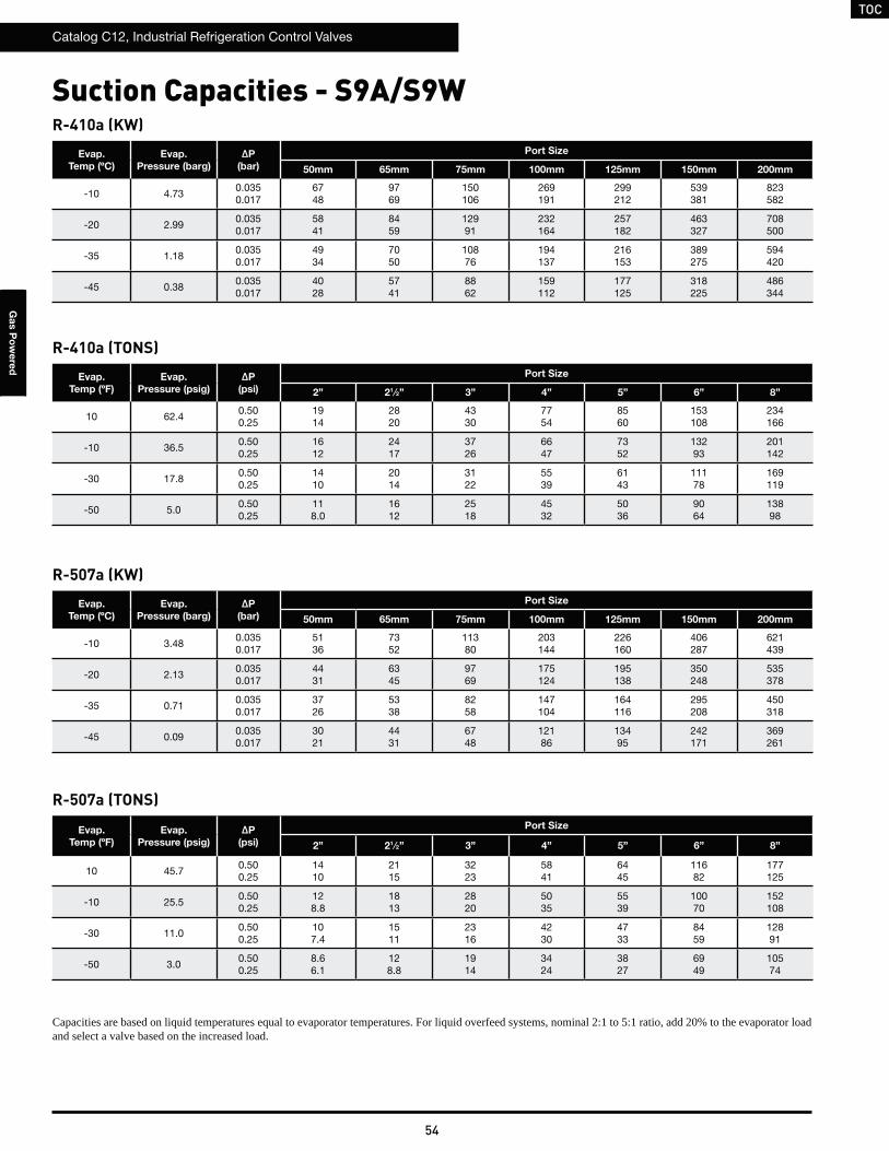
TOC
Catalog C12, Industrial Refrigeration Control Valves
54
Ga
s P
ow
ere
d
Suction Capacities - S9A/S9WR-410a (KW)
R-410a (TONS)
Evap.
Temp (ºC)
Evap.
Pressure (barg)
ΔP
(bar)
Port Size
50mm 65mm 75mm 100mm 125mm 150mm 200mm
-10 4.730.0350.017
6748
9769
150106
269191
299212
539381
823582
-20 2.990.0350.017
5841
8459
12991
232164
257182
463327
708500
-35 1.180.0350.017
4934
7050
10876
194137
216153
389275
594420
-45 0.380.0350.017
4028
5741
8862
159112
177125
318225
486344
Evap.
Temp (ºF)
Evap.
Pressure (psig)
ΔP
(psi)
Port Size
2” 21⁄2” 3” 4” 5” 6” 8”
10 62.40.500.25
1914
2820
4330
7754
8560
153108
234166
-10 36.50.500.25
1612
2417
3726
6647
7352
13293
201142
-30 17.80.500.25
1410
2014
3122
5539
6143
11178
169119
-50 5.00.500.25
118.0
1612
2518
4532
5036
9064
13898
R-507a (KW)
R-507a (TONS)
Evap.
Temp (ºC)
Evap.
Pressure (barg)
ΔP
(bar)
Port Size
50mm 65mm 75mm 100mm 125mm 150mm 200mm
-10 3.480.0350.017
5136
7352
11380
203144
226160
406287
621439
-20 2.130.0350.017
4431
6345
9769
175124
195138
350248
535378
-35 0.710.0350.017
3726
5338
8258
147104
164116
295208
450318
-45 0.090.0350.017
3021
4431
6748
12186
13495
242171
369261
Evap.
Temp (ºF)
Evap.
Pressure (psig)
ΔP
(psi)
Port Size
2” 21⁄2” 3” 4” 5” 6” 8”
10 45.70.500.25
1410
2115
3223
5841
6445
11682
177125
-10 25.50.500.25
128.8
1813
2820
5035
5539
10070
152108
-30 11.00.500.25
107.4
1511
2316
4230
4733
8459
12891
-50 3.00.500.25
8.66.1
128.8
1914
3424
3827
6949
10574
Capacities are based on liquid temperatures equal to evaporator temperatures. For liquid overfeed systems, nominal 2:1 to 5:1 ratio, add 20% to the evaporator load and select a valve based on the increased load.
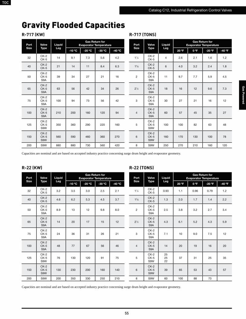
TOC
Catalog C12, Industrial Refrigeration Control Valves
55
Ga
s P
ow
ere
d
R-717 (KW) R-717 (TONS)
Port
Size
Valve
Type
Liquid
Leg
Gas Return for
Evaporator Temperature
-10 ºC -20 ºC -30 ºC -40 ºC
32CK-2CK-5
14 9.1 7.3 5.6 4.2
40CK-2CK-5
21 14 11 8.4 6.3
50CK-2CK-5S9A
39 34 27 21 16
65CK-2CK-5S9A
63 56 42 34 26
75CK-2CK-5S9A
100 94 73 56 42
100CK-2CK-5S9A
210 200 160 120 94
125CK-2CK-5S9W
350 360 290 220 160
150CK-2CK-5S9W
560 590 460 360 270
200 S9W 880 880 730 560 420
Capacities are nominal and are based on accepted industry practice concerning surge drum height and evaporator geometry.
Gravity Flooded Capacities
Port
Size
Valve
Type
Liquid
Leg
Gas Return for
Evaporator Temperature
20 ºF 0 ºF -20 ºF -40 ºF
11⁄4CK-2CK-5
4 2.6 2.1 1.6 1.2
15 ⁄8CK-2CK-5
6 4.0 3.2 2.4 1.8
2CK-2CK-5S9A
11 9.7 7.7 5.9 4.5
21⁄2CK-2CK-5S9A
18 16 12 9.6 7.3
3CK-2CK-5S9A
30 27 21 16 12
4CK-2CK-5S9A
60 57 45 35 27
5CK-2CK-5S9W
100 100 82 63 48
6CK-2CK-5S9W
160 170 130 100 78
8 S9W 250 270 210 160 120
R-22 (KW) R-22 (TONS)
Port
Size
Valve
Type
Liquid
Leg
Gas Return for
Evaporator Temperature
-10 ºC -20 ºC -30 ºC -40 ºC
32CK-2CK-5
3.2 3.5 3.0 2.5 2.1
40CK-2CK-5
4.6 6.2 5.3 4.5 3.7
50CK-2CK-5S9A
8.9 13 12 9.8 8.0
65CK-2CK-5S9A
14 20 17 15 12
75CK-2CK-5S9A
24 36 31 26 21
100CK-2CK-5S9A
48 77 67 56 46
125CK-2CK-5S9W
76 130 120 91 75
150CK-2CK-5S9W
130 230 200 160 140
200 S9W 200 350 330 250 210
Port
Size
Valve
Type
Liquid
Leg
Gas Return for
Evaporator Temperature
20 ºF 0 ºF -20 ºF -40 ºF
11⁄4CK-2CK-5
0.93 1.1 0.96 0.79 1.2
15 ⁄8CK-2CK-5
1.3 2.0 1.7 1.4 2.2
2CK-2CK-5S9A
2.5 3.8 3.2 2.7 3.4
21⁄2CK-2CK-5S9A
4.3 6.1 5.2 4.3 5.9
3CK-2CK-5S9A
7.1 10 9.0 7.5 12
4CK-2CK-5S9A
14 20 19 16 20
5CK-2CK-5S9W
252522
37 31 25 35
6CK-2CK-5S9W
39 65 53 43 57
8 S9W 60 100 88 73
Capacities are nominal and are based on accepted industry practice concerning surge drum height and evaporator geometry.
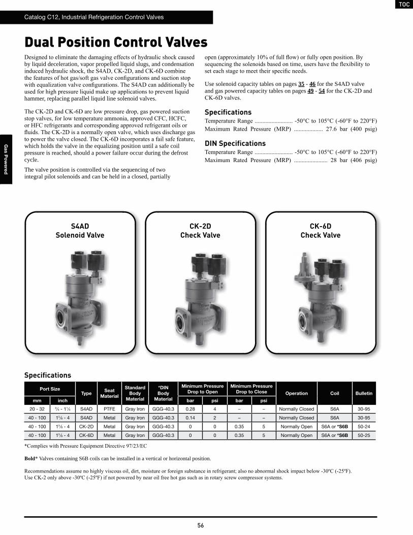
TOC
Catalog C12, Industrial Refrigeration Control Valves
56
Ga
s P
ow
ere
d
Dual Position Control Valves
S4ADSolenoid Valve
CK-2DCheck Valve
CK-6DCheck Valve
by liquid deceleration, vapor propelled liquid slugs, and condensation
hammer, replacing parallel liquid line solenoid valves.
which holds the valve in the equalizing position until a safe coil pressure is reached, should a power failure occur during the defrost cycle.The valve position is controlled via the sequencing of two integral pilot solenoids and can be held in a closed, partially
Specifications
Use solenoid capacity tables on pages 35 - 46 for the S4AD valve and gas powered capacity tables on pages 49 - 54
Specifications
DIN Specifications
Valves containing S6B coils can be installed in a vertical or horizontal position.
Port SizeType
Seat
Material
Standard
Body
Material
*DIN
Body
Material
Minimum Pressure
Drop to Open
Minimum Pressure
Drop to Close Operation Coil Bulletin
mm inch bar psi bar psi
20 - 32 3 ⁄4 - 11⁄4 S4AD PTFE Gray Iron GGG-40.3 0.28 4 − − Normally Closed S6A 30-95
40 - 100 15 ⁄8 - 4 S4AD Metal Gray Iron GGG-40.3 0.14 2 − − Normally Closed S6A 30-95
40 - 100 15 ⁄8 - 4 CK-2D Metal Gray Iron GGG-40.3 0 0 0.35 5 Normally Open S6A or *S6B 50-24
40 - 100 15 ⁄8 - 4 CK-6D Metal Gray Iron GGG-40.3 0 0 0.35 5 Normally Open S6A or *S6B 50-25
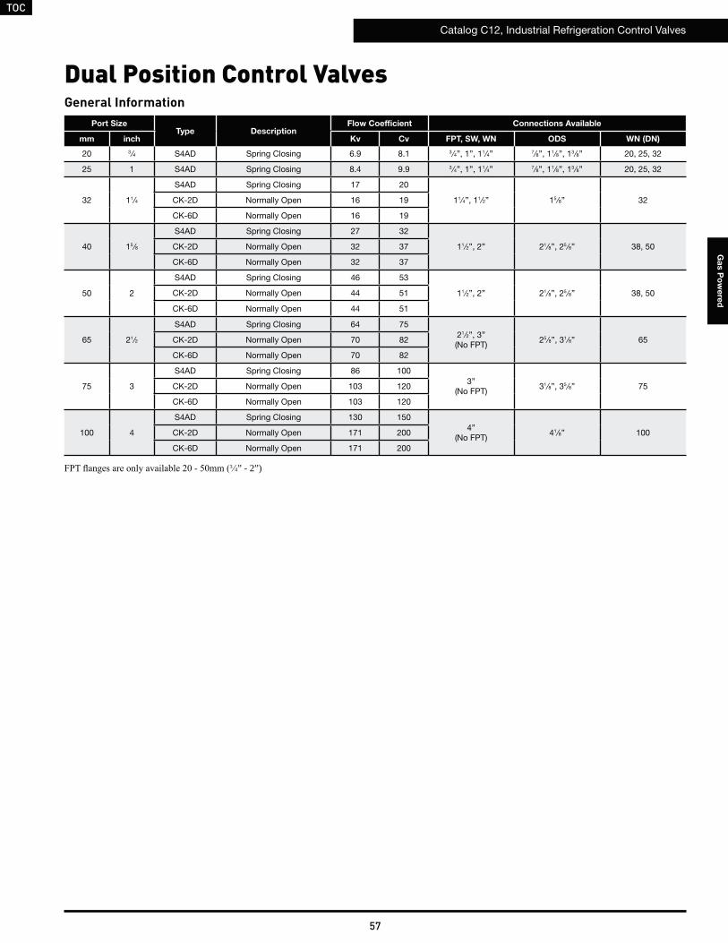
TOC
Catalog C12, Industrial Refrigeration Control Valves
57
Ga
s P
ow
ere
d
Port SizeType Description
Flow Coefficient Connections Available
mm inch Kv Cv FPT, SW, WN ODS WN (DN)
20 3 ⁄4 S4AD Spring Closing 6.9 8.1 3 ⁄4”, 1”, 11⁄4” 7⁄8”, 11⁄8”, 13 ⁄8” 20, 25, 32
25 1 S4AD Spring Closing 8.4 9.9 3 ⁄4”, 1”, 11⁄4” 7⁄8”, 11⁄8”, 13 ⁄8” 20, 25, 32
32 11⁄4
S4AD Spring Closing 17 20
11⁄4”, 11⁄2” 15 ⁄8” 32CK-2D Normally Open 16 19
CK-6D Normally Open 16 19
40 15 ⁄8
S4AD Spring Closing 27 32
11⁄2”, 2” 21⁄8”, 25 ⁄8” 38, 50CK-2D Normally Open 32 37
CK-6D Normally Open 32 37
50 2
S4AD Spring Closing 46 53
11⁄2”, 2” 21⁄8”, 25 ⁄8” 38, 50CK-2D Normally Open 44 51
CK-6D Normally Open 44 51
65 21⁄2
S4AD Spring Closing 64 7521⁄2”, 3”(No FPT)
25 ⁄8”, 31⁄8” 65CK-2D Normally Open 70 82
CK-6D Normally Open 70 82
75 3
S4AD Spring Closing 86 1003”
(No FPT)31⁄8”, 35 ⁄8” 75CK-2D Normally Open 103 120
CK-6D Normally Open 103 120
100 4
S4AD Spring Closing 130 1504”
(No FPT)41⁄8” 100CK-2D Normally Open 171 200
CK-6D Normally Open 171 200
General Information
3 4” - 2”)
Dual Position Control Valves
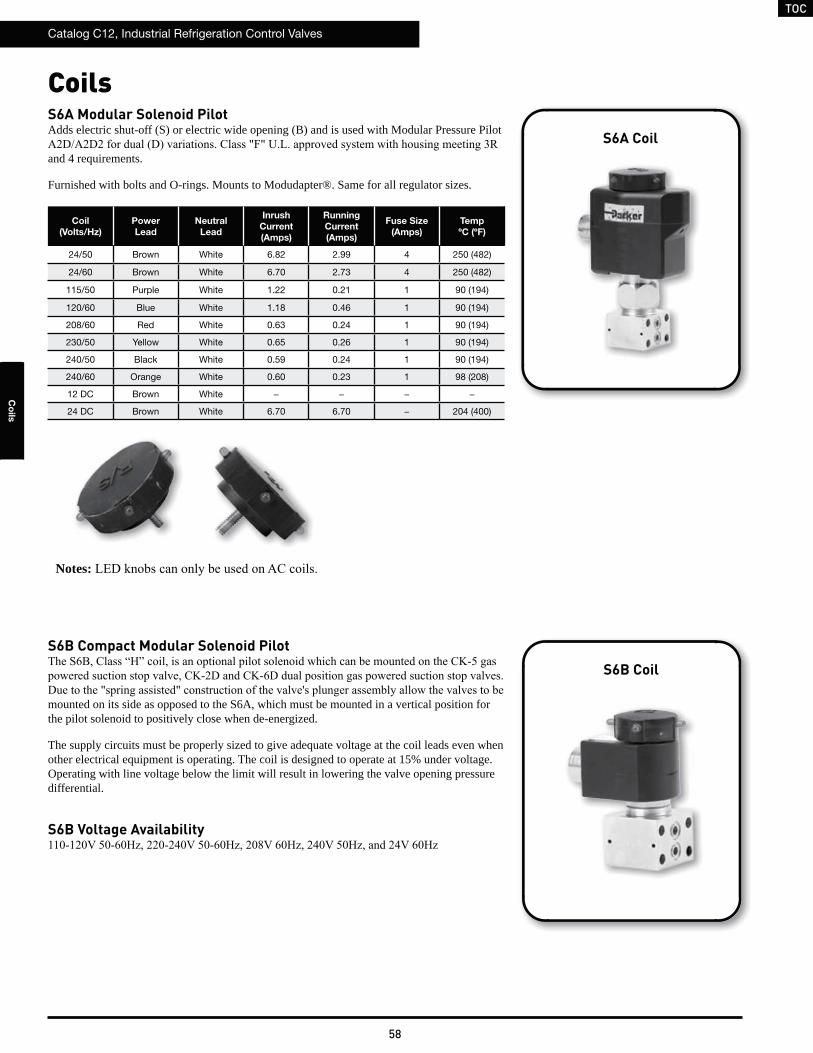
TOC
Catalog C12, Industrial Refrigeration Control Valves
58
Co
ils
S6A Modular Solenoid PilotAdds electric shut-off (S) or electric wide opening (B) and is used with Modular Pressure Pilot
and 4 requirements.
Furnished with bolts and O-rings. Mounts to Modudapter®. Same for all regulator sizes.
S6B Compact Modular Solenoid Pilot
mounted on its side as opposed to the S6A, which must be mounted in a vertical position for the pilot solenoid to positively close when de-energized.
The supply circuits must be properly sized to give adequate voltage at the coil leads even when other electrical equipment is operating. The coil is designed to operate at 15% under voltage. Operating with line voltage below the limit will result in lowering the valve opening pressure differential.
Coil
(Volts/Hz)
Power
Lead
Neutral
Lead
Inrush
Current
(Amps)
Running
Current
(Amps)
Fuse Size
(Amps)
Temp
ºC (ºF)
24/50 Brown White 6.82 2.99 4 250 (482)
24/60 Brown White 6.70 2.73 4 250 (482)
115/50 Purple White 1.22 0.21 1 90 (194)
120/60 Blue White 1.18 0.46 1 90 (194)
208/60 Red White 0.63 0.24 1 90 (194)
230/50 Yellow White 0.65 0.26 1 90 (194)
240/50 Black White 0.59 0.24 1 90 (194)
240/60 Orange White 0.60 0.23 1 98 (208)
12 DC Brown White − − − −
24 DC Brown White 6.70 6.70 − 204 (400)
Coils
Notes:
S6A Coil
S6B Coil
S6B Voltage Availability
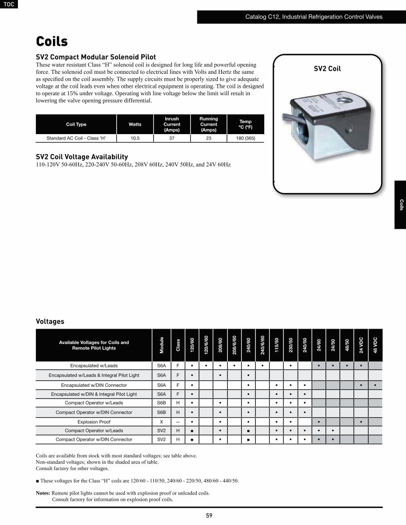
TOC
Catalog C12, Industrial Refrigeration Control Valves
59
Co
ils
Coils
Consult factory for other voltages.
Notes:Consult factory for information on explosion proof coils.
Available Voltages for Coils and
Remote Pilot Lights
Mo
du
le
Cla
ss
120/6
0
120/6
/60
208/6
0
208/6
/60
240/6
0
240/6
/60
115/5
0
230/5
0
240/5
0
24/6
0
24/5
0
48/5
0
24 V
DC
48 V
DC
Encapsulated w/Leads S6A F
Encapsulated w/Leads & Integral Pilot Light S6A F
Encapsulated w/DIN Connector S6A F
Encapsulated w/DIN & Integral Pilot Light S6A F
Compact Operator w/Leads S6B H
Compact Operator w/DIN Connector S6B H
Explosion Proof X —
Compact Operator w/Leads SV2 H
Compact Operator w/DIN Connector SV2 H
Voltages
Coil Type Watts
Inrush
Current
(Amps)
Running
Current
(Amps)
Temp
ºC (ºF)
Standard AC Coil - Class ‘H’ 10.5 37 23 180 (365)
SV2 Coil Voltage Availability
SV2 CoilSV2 Compact Modular Solenoid Pilot
voltage at the coil leads even when other electrical equipment is operating. The coil is designed to operate at 15% under voltage. Operating with line voltage below the limit will result in lowering the valve opening pressure differential.
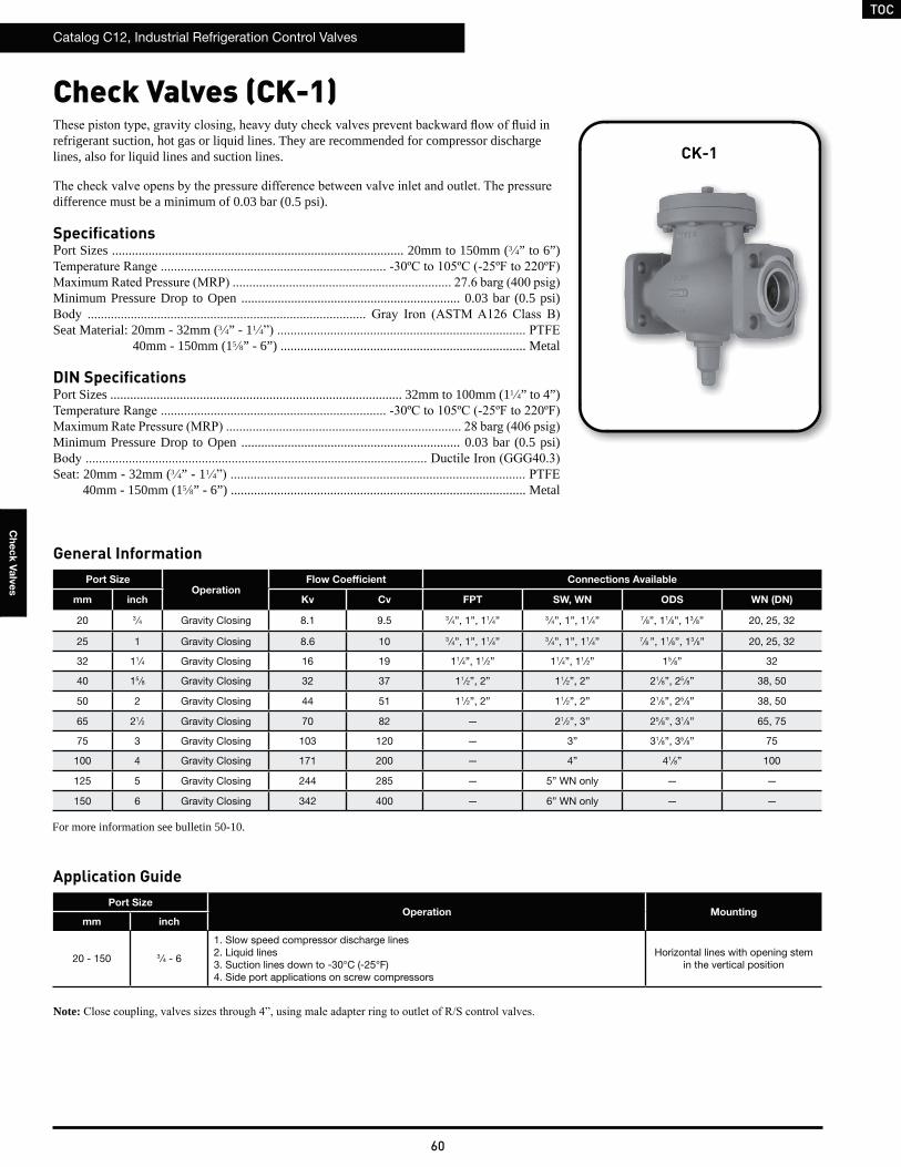
TOC
Catalog C12, Industrial Refrigeration Control Valves
60
Ch
ec
k V
alv
es
Check Valves (CK-1)
Application GuidePort Size
Operation Mountingmm inch
20 - 150 3 ⁄4 - 6
1. Slow speed compressor discharge lines2. Liquid lines3. Suction lines down to -30°C (-25°F)4. Side port applications on screw compressors
Horizontal lines with opening stem in the vertical position
Note:
Port SizeOperation
Flow Coefficient Connections Available
mm inch Kv Cv FPT SW, WN ODS WN (DN)
20 3 ⁄4 Gravity Closing 8.1 9.5 3 ⁄4”, 1”, 11⁄4” 3 ⁄4”, 1”, 11⁄4” 7⁄8”, 11⁄8”, 13 ⁄8” 20, 25, 32
25 1 Gravity Closing 8.6 10 3 ⁄4”, 1”, 11⁄4” 3 ⁄4”, 1”, 11⁄4” 7⁄8 ”, 11⁄8”, 13 ⁄8” 20, 25, 32
32 11⁄4 Gravity Closing 16 19 11⁄4”, 11⁄2” 11⁄4”, 11⁄2” 15 ⁄8” 32
40 15 ⁄8 Gravity Closing 32 37 11⁄2”, 2” 11⁄2”, 2” 21⁄8”, 25 ⁄8” 38, 50
50 2 Gravity Closing 44 51 11⁄2”, 2” 11⁄2”, 2” 21⁄8”, 25 ⁄8” 38, 50
65 21⁄2 Gravity Closing 70 82 — 21⁄2”, 3” 25 ⁄8”, 31⁄8” 65, 75
75 3 Gravity Closing 103 120 — 3” 31⁄8”, 35 ⁄8” 75
100 4 Gravity Closing 171 200 — 4” 41⁄8” 100
125 5 Gravity Closing 244 285 — 5” WN only — —
150 6 Gravity Closing 342 400 — 6” WN only — —
refrigerant suction, hot gas or liquid lines. They are recommended for compressor discharge lines, also for liquid lines and suction lines.
difference must be a minimum of 0.03 bar (0.5 psi).
SpecificationsPort Sizes ........................................................................................ 20mm to 150mm (3 4” to 6”)
Minimum Pressure Drop to Open .................................................................. 0.03 bar (0.5 psi)
Seat Material: 20mm - 32mm (3 4” - 11 4
40mm - 150mm (15 8” - 6”) .......................................................................... Metal
DIN SpecificationsPort Sizes ........................................................................................ 32mm to 100mm (11 4” to 4”)
Minimum Pressure Drop to Open .................................................................. 0.03 bar (0.5 psi)
Seat: 20mm - 32mm (3 4” - 11 4
40mm - 150mm (15 8” - 6”) ......................................................................................... Metal
CK-1
General Information
For more information see bulletin 50-10.
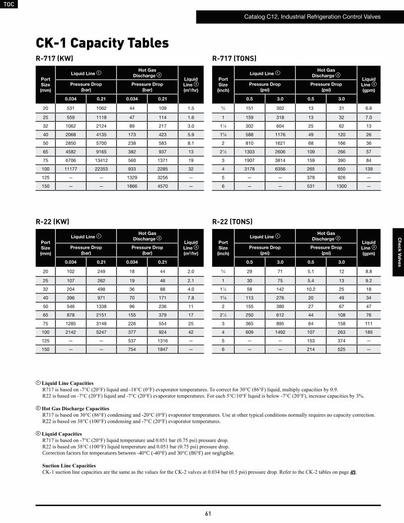
TOC
Catalog C12, Industrial Refrigeration Control Valves
61
Ch
ec
k V
alv
es
R-717 (KW)
Port
Size
(mm)
Liquid Line 1Hot Gas
Discharge 2
Liquid
Line 3
(m3/hr)
Pressure Drop
(bar)
Pressure Drop
(bar)
0.034 0.21 0.034 0.21
20 531 1062 44 109 1.5
25 559 1118 47 114 1.6
32 1062 2124 89 217 3.0
40 2068 4135 173 423 5.9
50 2850 5700 238 583 8.1
65 4582 9165 382 937 13
75 6706 13412 560 1371 19
100 11177 22353 933 2285 32
125 — — 1329 3256 —
150 — — 1866 4570 —
CK-1 Capacity TablesR-717 (TONS)
Port
Size
(inch)
Liquid Line 1Hot Gas
Discharge 2
Liquid
Line 3
(gpm)
Pressure Drop
(psi)
Pressure Drop
(psi)
0.5 3.0 0.5 3.0
3 ⁄4 151 302 13 31 6.6
1 159 318 13 32 7.0
11⁄4 302 604 25 62 13
15 ⁄8 588 1176 49 120 26
2 810 1621 68 166 36
21⁄2 1303 2606 109 266 57
3 1907 3814 159 390 84
4 3178 6356 265 650 139
5 — — 378 926 —
6 — — 531 1300 —
R-22 (KW)
Port
Size
(mm)
Liquid Line 1Hot Gas
Discharge 2
Liquid
Line 3
(m3/hr)
Pressure Drop
(bar)
Pressure Drop
(bar)
0.034 0.21 0.034 0.21
20 102 249 18 44 2.0
25 107 262 19 46 2.1
32 204 498 36 88 4.0
40 396 971 70 171 7.8
50 546 1338 96 236 11
65 878 2151 155 379 17
75 1285 3148 226 554 25
100 2142 5247 377 924 42
125 — — 537 1316 —
150 — — 754 1847 —
R-22 (TONS)
Port
Size
(inch)
Liquid Line 1Hot Gas
Discharge 2
Liquid
Line 3
(gpm)
Pressure Drop
(psi)
Pressure Drop
(psi)
0.5 3.0 0.5 3.0
3 ⁄4 29 71 5.1 12 8.8
1 30 75 5.4 13 9.2
11⁄4 58 142 10.2 25 18
15 ⁄8 113 276 20 49 34
2 155 380 27 67 47
21⁄2 250 612 44 108 76
3 365 895 64 158 111
4 609 1492 107 263 185
5 — — 153 374 —
6 — — 214 525 —
1
2
3
Correction factors for temperatures between -40°C (-40°F) and 30°C (86°F) are negligible.
49.
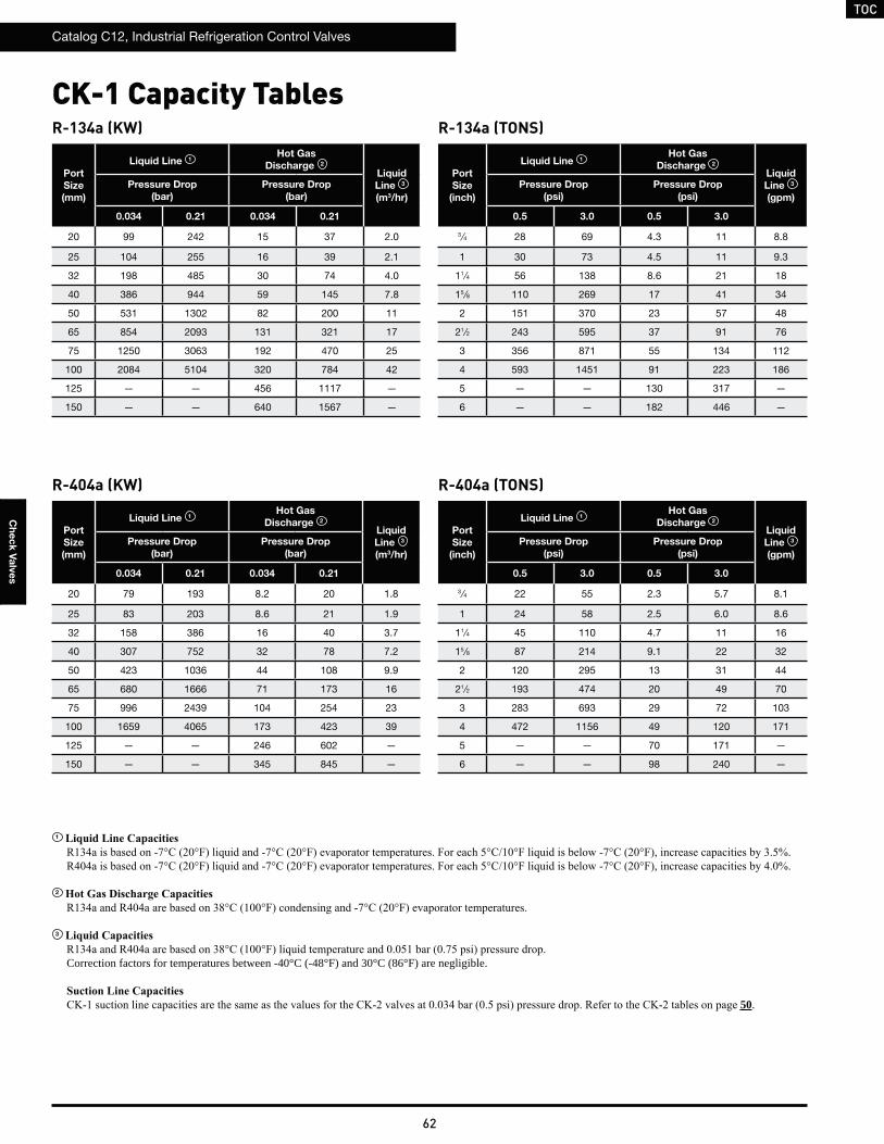
TOC
Catalog C12, Industrial Refrigeration Control Valves
62
Ch
ec
k V
alv
es
R-134a (KW)
Port
Size
(mm)
Liquid Line 1Hot Gas
Discharge 2
Liquid
Line 3
(m3/hr)
Pressure Drop
(bar)
Pressure Drop
(bar)
0.034 0.21 0.034 0.21
20 99 242 15 37 2.0
25 104 255 16 39 2.1
32 198 485 30 74 4.0
40 386 944 59 145 7.8
50 531 1302 82 200 11
65 854 2093 131 321 17
75 1250 3063 192 470 25
100 2084 5104 320 784 42
125 — — 456 1117 —
150 — — 640 1567 —
R-134a (TONS)
Port
Size
(inch)
Liquid Line 1Hot Gas
Discharge 2
Liquid
Line 3
(gpm)
Pressure Drop
(psi)
Pressure Drop
(psi)
0.5 3.0 0.5 3.0
3 ⁄4 28 69 4.3 11 8.8
1 30 73 4.5 11 9.3
11⁄4 56 138 8.6 21 18
15 ⁄8 110 269 17 41 34
2 151 370 23 57 48
21⁄2 243 595 37 91 76
3 356 871 55 134 112
4 593 1451 91 223 186
5 — — 130 317 —
6 — — 182 446 —
R-404a (KW)
Port
Size
(mm)
Liquid Line 1Hot Gas
Discharge 2
Liquid
Line 3
(m3/hr)
Pressure Drop
(bar)
Pressure Drop
(bar)
0.034 0.21 0.034 0.21
20 79 193 8.2 20 1.8
25 83 203 8.6 21 1.9
32 158 386 16 40 3.7
40 307 752 32 78 7.2
50 423 1036 44 108 9.9
65 680 1666 71 173 16
75 996 2439 104 254 23
100 1659 4065 173 423 39
125 — — 246 602 —
150 — — 345 845 —
R-404a (TONS)
Port
Size
(inch)
Liquid Line 1Hot Gas
Discharge 2
Liquid
Line 3
(gpm)
Pressure Drop
(psi)
Pressure Drop
(psi)
0.5 3.0 0.5 3.0
3 ⁄4 22 55 2.3 5.7 8.1
1 24 58 2.5 6.0 8.6
11⁄4 45 110 4.7 11 16
15 ⁄8 87 214 9.1 22 32
2 120 295 13 31 44
21⁄2 193 474 20 49 70
3 283 693 29 72 103
4 472 1156 49 120 171
5 — — 70 171 —
6 — — 98 240 —
CK-1 Capacity Tables
1
2
3
Correction factors for temperatures between -40°C (-48°F) and 30°C (86°F) are negligible.
50.
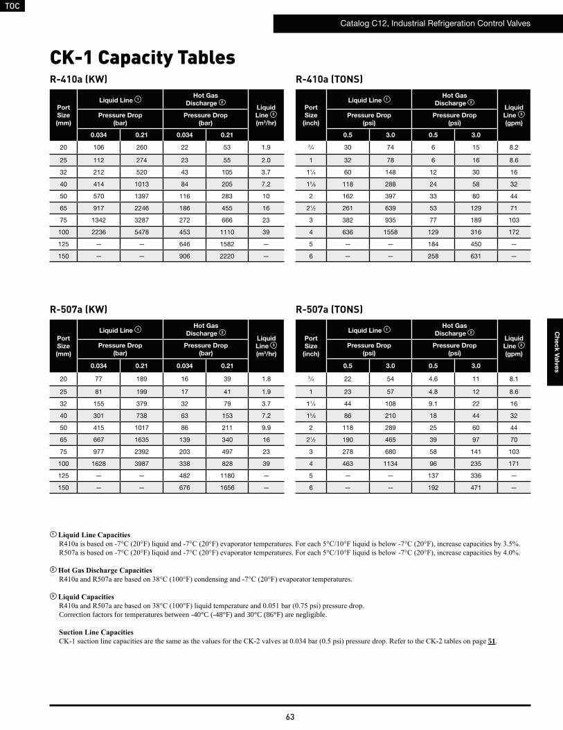
TOC
Catalog C12, Industrial Refrigeration Control Valves
63
Ch
ec
k V
alv
es
R-410a (KW)
Port
Size
(mm)
Liquid Line 1Hot Gas
Discharge 2
Liquid
Line 3
(m3/hr)
Pressure Drop
(bar)
Pressure Drop
(bar)
0.034 0.21 0.034 0.21
20 106 260 22 53 1.9
25 112 274 23 55 2.0
32 212 520 43 105 3.7
40 414 1013 84 205 7.2
50 570 1397 116 283 10
65 917 2246 186 455 16
75 1342 3287 272 666 23
100 2236 5478 453 1110 39
125 — — 646 1582 —
150 — — 906 2220 —
R-410a (TONS)
Port
Size
(inch)
Liquid Line 1Hot Gas
Discharge 2
Liquid
Line 3
(gpm)
Pressure Drop
(psi)
Pressure Drop
(psi)
0.5 3.0 0.5 3.0
3 ⁄4 30 74 6 15 8.2
1 32 78 6 16 8.6
11⁄4 60 148 12 30 16
15 ⁄8 118 288 24 58 32
2 162 397 33 80 44
21⁄2 261 639 53 129 71
3 382 935 77 189 103
4 636 1558 129 316 172
5 — — 184 450 —
6 — — 258 631 —
R-507a (KW)
Port
Size
(mm)
Liquid Line 1Hot Gas
Discharge 2
Liquid
Line 3
(m3/hr)
Pressure Drop
(bar)
Pressure Drop
(bar)
0.034 0.21 0.034 0.21
20 77 189 16 39 1.8
25 81 199 17 41 1.9
32 155 379 32 79 3.7
40 301 738 63 153 7.2
50 415 1017 86 211 9.9
65 667 1635 139 340 16
75 977 2392 203 497 23
100 1628 3987 338 828 39
125 — — 482 1180 —
150 — — 676 1656 —
R-507a (TONS)
Port
Size
(inch)
Liquid Line 1Hot Gas
Discharge 2
Liquid
Line 3
(gpm)
Pressure Drop
(psi)
Pressure Drop
(psi)
0.5 3.0 0.5 3.0
3 ⁄4 22 54 4.6 11 8.1
1 23 57 4.8 12 8.6
11⁄4 44 108 9.1 22 16
15 ⁄8 86 210 18 44 32
2 118 289 25 60 44
21⁄2 190 465 39 97 70
3 278 680 58 141 103
4 463 1134 96 235 171
5 — — 137 336 —
6 — — 192 471 —
CK-1 Capacity Tables
1
2
3
Correction factors for temperatures between -40°C (-48°F) and 30°C (86°F) are negligible.
51.
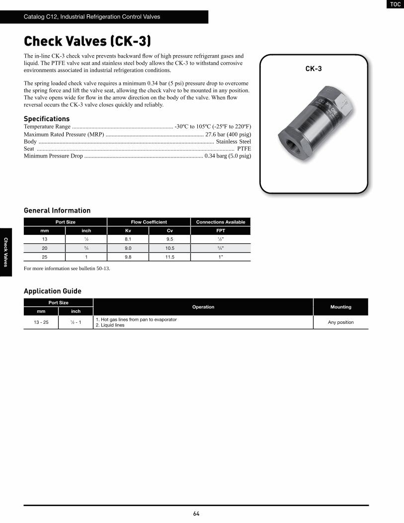
TOC
Catalog C12, Industrial Refrigeration Control Valves
64
Ch
ec
k V
alv
es
Check Valves (CK-3)
Application GuidePort Size
Operation Mountingmm inch
13 - 25 1⁄2 - 11. Hot gas lines from pan to evaporator2. Liquid lines
Any position
General InformationPort Size Flow Coefficient Connections Available
mm inch Kv Cv FPT
13 1⁄2 8.1 9.5 1⁄2”
20 3 ⁄4 9.0 10.5 3 ⁄4”
25 1 9.8 11.5 1”
environments associated in industrial refrigeration conditions.
Specifications
.................................................................. 27.6 bar (400 psig)Body ...................................................................................................................... Stainless Steel
Minimum Pressure Drop ................................................................................ 0.34 barg (5.0 psig)
CK-3
For more information see bulletin 50-13.
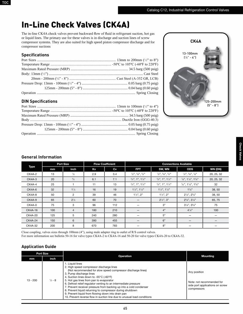
TOC
Catalog C12, Industrial Refrigeration Control Valves
65
Ch
ec
k V
alv
es
In-Line Check Valves (CK4A)
Application GuidePort Size
Operation Mountingmm inch
13 - 200 1⁄2 - 8
1. Liquid lines2. High speed compressor discharge lines (Not recommended for slow speed compressor discharge lines)3. Pump discharge lines4. Suction lines down to -55°C (-60°F)5. Hot gas lines from pan to evaporator6. Defrost relief regulator venting to an intermediate pressure7. Prevent receiver pressure from backing up into a cold condenser8. Prevent liquid returning to compressor during shutdown9. Prevent liquid from flowing down into drain pan10. Prevent reverse flow in suction line due to unusual load conditions
Any position
Note: not recommended for side port applications on screw compressors
General Information
TypePort Size Flow Coefficient Connections Available
mm inch Kv Cv FPT SW, WN ODS WN (DN)
CK4A-2 13 1⁄2 2.9 3.4 1⁄2”, 3 ⁄8”, 3 ⁄4” 1 ⁄2”, 3 ⁄8”, 3 ⁄4” 1 ⁄2”, 5 ⁄8”, 7⁄8” 20, 25, 32
CK4A-3 20 3 ⁄4 6.1 7.1 3 ⁄4”, 1”, 11⁄4” 3 ⁄4”, 1”, 11⁄4” 7⁄8”, 11⁄8”, 13 ⁄8” 20, 25, 32
CK4A-4 25 1 11 13 3 ⁄4”, 1”, 11⁄4” 3 ⁄4”, 1”, 11⁄4” 7⁄8 ”, 11⁄8”, 13 ⁄8” 32
CK4A-6 32 11⁄4 16 19 11⁄4”, 11⁄2” 11⁄4”, 11⁄2” 15 ⁄8” 38, 50
CK4A-8 50 2 39 46 11⁄2”, 2” 11⁄2”, 2” 21⁄8”, 25 ⁄8” 38, 50
CK4A-9 65 21⁄2 60 70 — 21⁄2”, 3” 25 ⁄8”, 31⁄8” 65, 75
CK4A-0 75 3 96 112 — 3” 31⁄8”, 35 ⁄8” 75
CK4A-16 100 4 180 210 — 4” 41⁄8” 100
CK4A-20 125 5 240 280 — 5” — —
CK4A-24 150 6 390 455 — 6” — —
CK4A-32 200 8 670 783 — 8” — —
or liquid lines. The primary use for these valves is in discharge and suction lines of screw compressor systems. They are also suited for high speed piston compressor discharge and for compressor suctions
SpecificationsPort Sizes ........................................................................................ 13mm to 200mm (1 2” to 8”)
................................................................ 34.5 barg (500 psig)Body: 13mm (1 2”) ......................................................................................................... Cast Steel
20mm - 200mm (3 4
Pressure Drop: 13mm - 100mm (1 2” - 4”) ................................................... 0.05 barg (0.75 psig)125mm - 200mm (5” - 8”) .................................................. 0.04 barg (0.60 psig)
Operation .............................................................................................................. Spring Closing
DIN SpecificationsPort Sizes ........................................................................................ 13mm to 100mm (1 2” to 4”)
................................................................. 34.5 barg (500 psig)
Pressure Drop: 13mm - 100mm (1 2” - 4”) .................................................... 0.05 barg (0.75 psig)125mm - 200mm (5” - 8”) .................................................. 0.04 barg (0.60 psig)
Operation .............................................................................................................. Spring Closing
CK4A
125-200mm
(5” - 8”)
13-100mm
(1⁄2” - 4”)
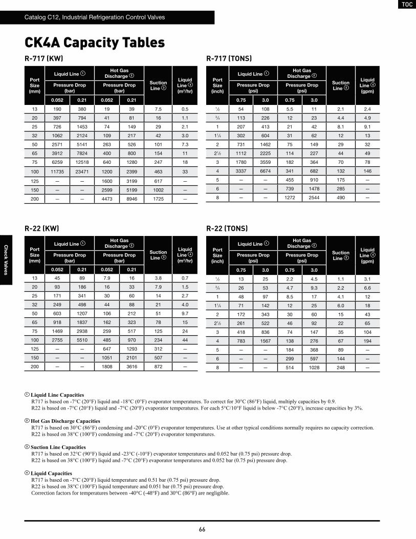
TOC
Catalog C12, Industrial Refrigeration Control Valves
66
Ch
ec
k V
alv
es
R-717 (KW)
Port
Size
(mm)
Liquid Line 1Hot Gas
Discharge 2
Suction
Line 3
Liquid
Line 4
(m3/hr)
Pressure Drop
(bar)
Pressure Drop
(bar)
0.052 0.21 0.052 0.21
13 190 380 19 39 7.5 0.5
20 397 794 41 81 16 1.1
25 726 1453 74 149 29 2.1
32 1062 2124 109 217 42 3.0
50 2571 5141 263 526 101 7.3
65 3912 7824 400 800 154 11
75 6259 12518 640 1280 247 18
100 11735 23471 1200 2399 463 33
125 — — 1600 3199 617 —
150 — — 2599 5199 1002 —
200 — — 4473 8946 1725 —
R-717 (TONS)
Port
Size
(inch)
Liquid Line 1Hot Gas
Discharge 2
Suction
Line 3
Liquid
Line 4
(gpm)
Pressure Drop
(psi)
Pressure Drop
(psi)
0.75 3.0 0.75 3.0
1 ⁄2 54 108 5.5 11 2.1 2.4
3 ⁄4 113 226 12 23 4.4 4.9
1 207 413 21 42 8.1 9.1
11⁄4 302 604 31 62 12 13
2 731 1462 75 149 29 32
21⁄2 1112 2225 114 227 44 49
3 1780 3559 182 364 70 78
4 3337 6674 341 682 132 146
5 — — 455 910 175 —
6 — — 739 1478 285 —
8 — — 1272 2544 490 —
CK4A Capacity Tables
R-22 (KW)
Port
Size
(mm)
Liquid Line 1Hot Gas
Discharge 2
Suction
Line 3
Liquid
Line 4
(m3/hr)
Pressure Drop
(bar)
Pressure Drop
(bar)
0.052 0.21 0.052 0.21
13 45 89 7.9 16 3.8 0.7
20 93 186 16 33 7.9 1.5
25 171 341 30 60 14 2.7
32 249 498 44 88 21 4.0
50 603 1207 106 212 51 9.7
65 918 1837 162 323 78 15
75 1469 2938 259 517 125 24
100 2755 5510 485 970 234 44
125 — — 647 1293 312 —
150 — — 1051 2101 507 —
200 — — 1808 3616 872 —
R-22 (TONS)
Port
Size
(inch)
Liquid Line 1Hot Gas
Discharge 2
Suction
Line 3
Liquid
Line 4
(gpm)
Pressure Drop
(psi)
Pressure Drop
(psi)
0.75 3.0 0.75 3.0
1 ⁄2 13 25 2.2 4.5 1.1 3.1
3 ⁄4 26 53 4.7 9.3 2.2 6.6
1 48 97 8.5 17 4.1 12
11⁄4 71 142 12 25 6.0 18
2 172 343 30 60 15 43
21⁄2 261 522 46 92 22 65
3 418 836 74 147 35 104
4 783 1567 138 276 67 194
5 — — 184 368 89 —
6 — — 299 597 144 —
8 — — 514 1028 248 —
1
2
3
4
Correction factors for temperatures between -40°C (-48°F) and 30°C (86°F) are negligible.
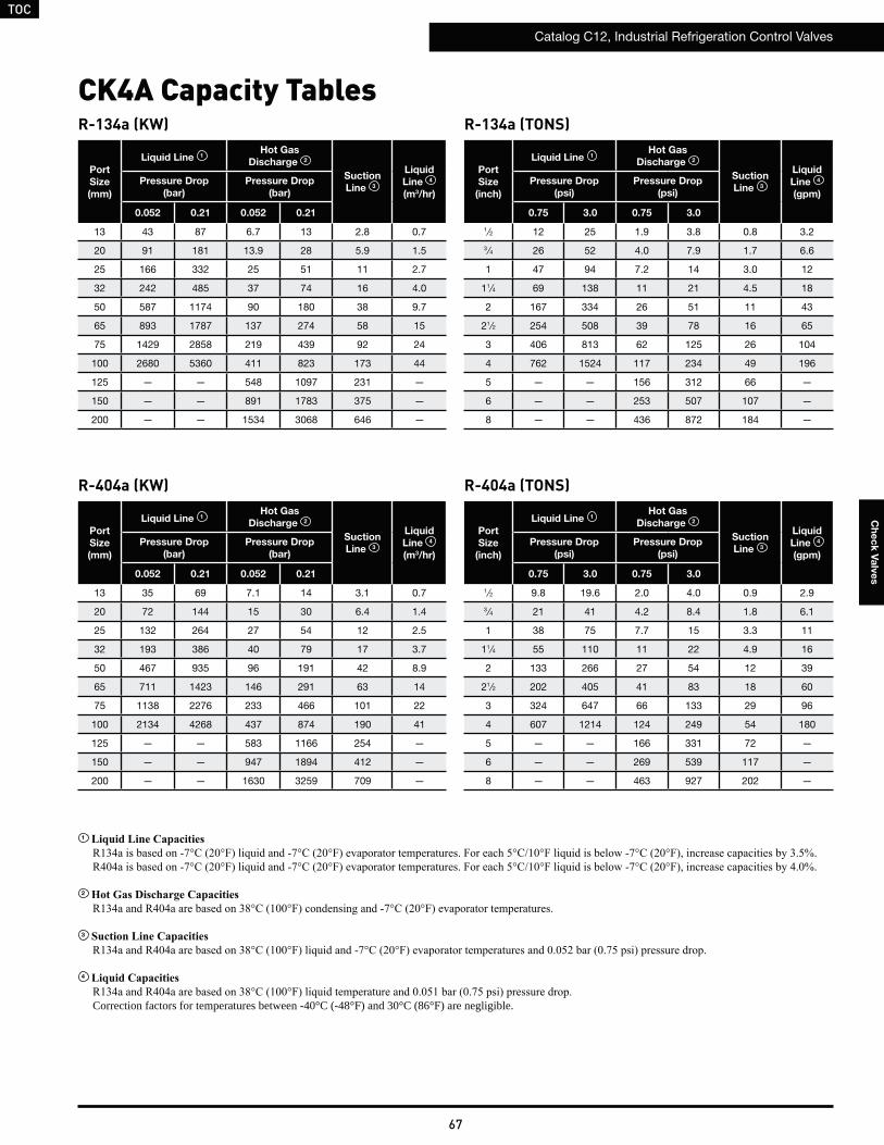
TOC
Catalog C12, Industrial Refrigeration Control Valves
67
Ch
ec
k V
alv
es
R-134a (KW)
Port
Size
(mm)
Liquid Line 1Hot Gas
Discharge 2
Suction
Line 3
Liquid
Line 4
(m3/hr)
Pressure Drop
(bar)
Pressure Drop
(bar)
0.052 0.21 0.052 0.21
13 43 87 6.7 13 2.8 0.7
20 91 181 13.9 28 5.9 1.5
25 166 332 25 51 11 2.7
32 242 485 37 74 16 4.0
50 587 1174 90 180 38 9.7
65 893 1787 137 274 58 15
75 1429 2858 219 439 92 24
100 2680 5360 411 823 173 44
125 — — 548 1097 231 —
150 — — 891 1783 375 —
200 — — 1534 3068 646 —
R-134a (TONS)
Port
Size
(inch)
Liquid Line 1Hot Gas
Discharge 2
Suction
Line 3
Liquid
Line 4
(gpm)
Pressure Drop
(psi)
Pressure Drop
(psi)
0.75 3.0 0.75 3.0
1 ⁄2 12 25 1.9 3.8 0.8 3.2
3 ⁄4 26 52 4.0 7.9 1.7 6.6
1 47 94 7.2 14 3.0 12
11⁄4 69 138 11 21 4.5 18
2 167 334 26 51 11 43
21⁄2 254 508 39 78 16 65
3 406 813 62 125 26 104
4 762 1524 117 234 49 196
5 — — 156 312 66 —
6 — — 253 507 107 —
8 — — 436 872 184 —
CK4A Capacity Tables
R-404a (KW)
Port
Size
(mm)
Liquid Line 1Hot Gas
Discharge 2
Suction
Line 3
Liquid
Line 4
(m3/hr)
Pressure Drop
(bar)
Pressure Drop
(bar)
0.052 0.21 0.052 0.21
13 35 69 7.1 14 3.1 0.7
20 72 144 15 30 6.4 1.4
25 132 264 27 54 12 2.5
32 193 386 40 79 17 3.7
50 467 935 96 191 42 8.9
65 711 1423 146 291 63 14
75 1138 2276 233 466 101 22
100 2134 4268 437 874 190 41
125 — — 583 1166 254 —
150 — — 947 1894 412 —
200 — — 1630 3259 709 —
R-404a (TONS)
Port
Size
(inch)
Liquid Line 1Hot Gas
Discharge 2
Suction
Line 3
Liquid
Line 4
(gpm)
Pressure Drop
(psi)
Pressure Drop
(psi)
0.75 3.0 0.75 3.0
1 ⁄2 9.8 19.6 2.0 4.0 0.9 2.9
3 ⁄4 21 41 4.2 8.4 1.8 6.1
1 38 75 7.7 15 3.3 11
11⁄4 55 110 11 22 4.9 16
2 133 266 27 54 12 39
21⁄2 202 405 41 83 18 60
3 324 647 66 133 29 96
4 607 1214 124 249 54 180
5 — — 166 331 72 —
6 — — 269 539 117 —
8 — — 463 927 202 —
1
2
3
4
Correction factors for temperatures between -40°C (-48°F) and 30°C (86°F) are negligible.
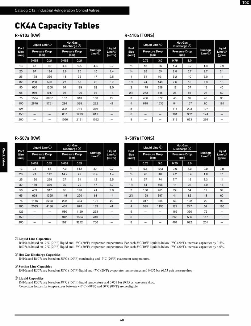
TOC
Catalog C12, Industrial Refrigeration Control Valves
68
Ch
ec
k V
alv
es
R-410a (KW)
Port
Size
(mm)
Liquid Line 1Hot Gas
Discharge 2
Suction
Line 3
Liquid
Line 4
(m3/hr)
Pressure Drop
(bar)
Pressure Drop
(bar)
0.052 0.21 0.052 0.21
13 47 93 4.8 9.5 4.6 0.7
20 97 194 9.9 20 10 1.4
25 178 356 18 36 17 2.5
32 260 520 27 53 26 3.7
50 630 1260 64 129 62 9.0
65 959 1917 98 196 94 14
75 1534 3067 157 313 150 22
100 2876 5751 294 588 282 41
125 — — 392 784 376 —
150 — — 637 1273 611 —
200 — — 1096 2191 1052 —
R-410a (TONS)
Port
Size
(inch)
Liquid Line 1Hot Gas
Discharge 2
Suction
Line 3
Liquid
Line 4
(gpm)
Pressure Drop
(psi)
Pressure Drop
(psi)
0.75 3.0 0.75 3.0
1 ⁄2 13 26 1.4 2.7 1.3 2.9
3 ⁄4 28 55 2.8 5.7 2.7 6.1
1 51 101 5.2 10 5.0 11
11⁄4 74 148 7.6 15 7.3 16
2 179 358 18 37 18 40
21⁄2 273 545 28 56 27 60
3 436 872 45 89 43 96
4 818 1635 84 167 80 181
5 — — 111 223 107 —
6 — — 181 362 174 —
8 — — 312 623 299 —
CK4A Capacity Tables
R-507a (KW)
Port
Size
(mm)
Liquid Line 1Hot Gas
Discharge 2
Suction
Line 3
Liquid
Line 4
(m3/hr)
Pressure Drop
(bar)
Pressure Drop
(bar)
0.052 0.21 0.052 0.21
13 34 68 7.0 14.1 3.1 0.7
20 71 142 14.7 29 6.4 1.4
25 130 259 27 54 12 2.5
32 189 379 39 79 17 3.7
50 459 917 95 190 41 9.0
65 698 1395 145 290 63 14
75 1116 2233 232 464 101 22
100 2093 4186 435 870 189 41
125 — — 580 1159 253 —
150 — — 942 1884 410 —
200 — — 1621 3242 706 —
R-507a (TONS)
Port
Size
(inch)
Liquid Line 1Hot Gas
Discharge 2
Suction
Line 3
Liquid
Line 4
(gpm)
Pressure Drop
(psi)
Pressure Drop
(psi)
0.75 3.0 0.75 3.0
1 ⁄2 9.6 19.3 2.0 4.0 0.9 2.9
3 ⁄4 20 40 4.2 8.4 1.8 6.1
1 37 74 7.7 15 3.3 11
11⁄4 54 108 11 22 4.9 16
2 130 261 27 54 12 39
21⁄2 198 397 41 82 18 60
3 317 635 66 132 29 96
4 595 1190 124 247 54 180
5 — — 165 330 72 —
6 — — 268 536 117 —
8 — — 461 922 201 —
1
2
3
4
Correction factors for temperatures between -40°C (-48°F) and 30°C (86°F) are negligible.
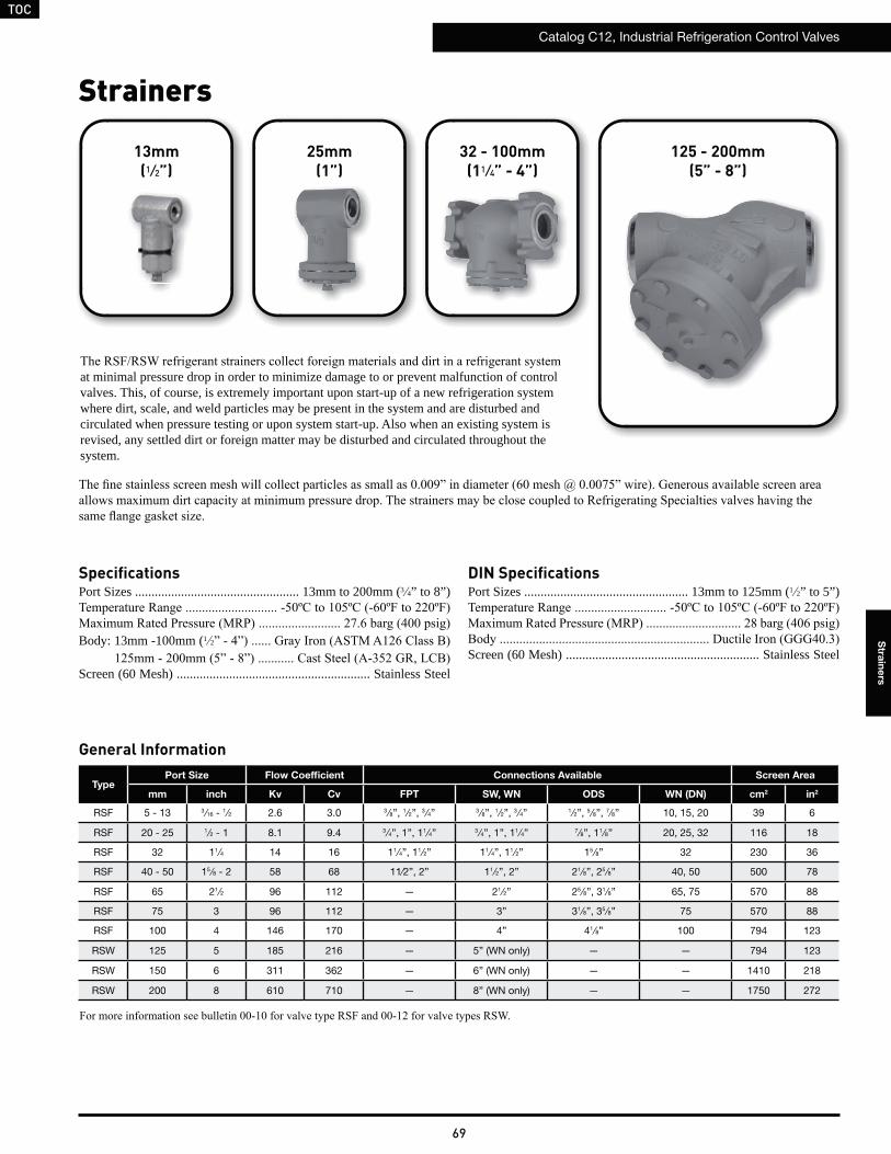
TOC
Catalog C12, Industrial Refrigeration Control Valves
69
Stra
ine
rs
Strainers
General Information
TypePort Size Flow Coefficient Connections Available Screen Area
mm inch Kv Cv FPT SW, WN ODS WN (DN) cm2 in2
RSF 5 - 13 3 ⁄16 - 1 ⁄2 2.6 3.0 3 ⁄8”, 1 ⁄2”, 3 ⁄4” 3 ⁄8”, 1 ⁄2”, 3 ⁄4” 1 ⁄2”, 5 ⁄8”, 7⁄8” 10, 15, 20 39 6
RSF 20 - 25 1⁄2 - 1 8.1 9.4 3 ⁄4”, 1”, 11⁄4” 3 ⁄4”, 1”, 11⁄4” 7⁄8”, 11⁄8” 20, 25, 32 116 18
RSF 32 11⁄4 14 16 11⁄4”, 11⁄2” 11⁄4”, 11⁄2” 15 ⁄8” 32 230 36
RSF 40 - 50 15 ⁄8 - 2 58 68 11⁄2”, 2” 11⁄2”, 2” 21⁄8”, 25 ⁄8” 40, 50 500 78
RSF 65 21⁄2 96 112 — 21⁄2” 25 ⁄8”, 31⁄8” 65, 75 570 88
RSF 75 3 96 112 — 3” 31⁄8”, 35 ⁄8” 75 570 88
RSF 100 4 146 170 — 4” 41⁄8” 100 794 123
RSW 125 5 185 216 — 5” (WN only) — — 794 123
RSW 150 6 311 362 — 6” (WN only) — — 1410 218
RSW 200 8 610 710 — 8” (WN only) — — 1750 272
SpecificationsPort Sizes .................................................. 13mm to 200mm (3 4” to 8”)
Body: 13mm -100mm (1 2
Screen (60 Mesh) ........................................................... Stainless Steel
at minimal pressure drop in order to minimize damage to or prevent malfunction of control valves. This, of course, is extremely important upon start-up of a new refrigeration system where dirt, scale, and weld particles may be present in the system and are disturbed and circulated when pressure testing or upon system start-up. Also when an existing system is revised, any settled dirt or foreign matter may be disturbed and circulated throughout the system.
125 - 200mm(5” - 8”)
32 - 100mm(11 ⁄4” - 4”)
25mm(1”)
13mm(1 ⁄2”)
DIN SpecificationsPort Sizes .................................................. 13mm to 125mm (1 2” to 5”)
Screen (60 Mesh) ........................................................... Stainless Steel
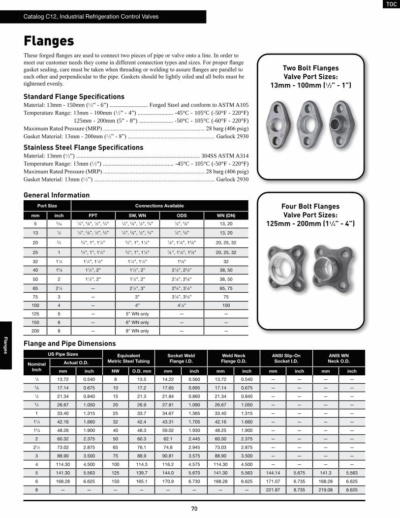
TOC
Catalog C12, Industrial Refrigeration Control Valves
70
Fla
ng
es
Flanges
tightened evenly.
Standard Flange SpecificationsMaterial: 13mm - 150mm (1 2” - 6”) .......................... Forged Steel and conform to ASTM A105
1 2” - 4”) ........................ -45°C - 105°C (-50°F - 220°F)125mm - 200mm (5” - 8”) ....................... -50°C - 105°C (-60°F - 220°F)
1 2
Stainless Steel Flange SpecificationsMaterial: 13mm (1 2”) .................................................................................... 304SS ASTM A314
1 2”) ................................................ -45°C - 105°C (-50°F - 220°F)
1 2
Port Size Connections Available
mm inch FPT SW, WN ODS WN (DN)
5 3 ⁄161 ⁄4”, 3 ⁄8”, 1 ⁄2”, 3 ⁄4” 1 ⁄4”, 3 ⁄8”, 1 ⁄2”, 3 ⁄4” 1 ⁄2”, 5 ⁄8” 13, 20
13 1⁄2 1 ⁄4”, 3 ⁄8”, 1 ⁄2”, 3 ⁄4” 1 ⁄4”, 3 ⁄8”, 1 ⁄2”, 3 ⁄4” 1 ⁄2”, 5 ⁄8” 13, 20
20 3 ⁄4 3 ⁄4”, 1”, 11⁄4” 3 ⁄4”, 1”, 11⁄4” 7⁄8”, 11⁄8”, 13 ⁄8” 20, 25, 32
25 1 3 ⁄4”, 1”, 11⁄4” 3 ⁄4”, 1”, 11⁄4” 7⁄8 ”, 11⁄8”, 13 ⁄8” 20, 25, 32
32 11⁄4 11⁄4”, 11⁄2” 11⁄4”, 11⁄2” 15 ⁄8” 32
40 15 ⁄8 11⁄2”, 2” 11⁄2”, 2” 21⁄8”, 25 ⁄8” 38, 50
50 2 11⁄2”, 2” 11⁄2”, 2” 21⁄8”, 25 ⁄8” 38, 50
65 21⁄2 — 21⁄2”, 3” 25 ⁄8”, 31⁄8” 65, 75
75 3 — 3” 31⁄8”, 35 ⁄8” 75
100 4 — 4” 41⁄8” 100
125 5 — 5” WN only — —
150 6 — 6” WN only — —
200 8 — 8” WN only — —
Four Bolt FlangesValve Port Sizes:
125mm - 200mm (11 ⁄4” - 4”)
General Information
US Pipe Sizes Equivalent
Metric Steel Tubing
Socket Weld
Flange I.D.
Weld Neck
Flange O.D.
ANSI Slip-On
Socket I.D.
ANIS WN
Neck O.D.Nominal
Inch
Actual O.D.
mm inch NW O.D. mm mm inch mm inch mm inch mm inch
1 ⁄4 13.72 0.540 8 13.5 14.22 0.560 13.72 0.540 — — — —
3⁄8 17.14 0.675 10 17.2 17.65 0.695 17.14 0.675 — — — —
1⁄2 21.34 0.840 15 21.3 21.84 0.860 21.34 0.840 — — — —
3⁄4 26.67 1.050 20 26.9 27.81 1.090 26.67 1.050 — — — —
1 33.40 1.315 25 33.7 34.67 1.365 33.40 1.315 — — — —
11⁄4 42.16 1.660 32 42.4 43.31 1.705 42.16 1.660 — — — —
15⁄8 48.26 1.900 40 48.3 59.02 1.930 48.25 1.900 — — — —
2 60.32 2.375 50 60.3 62.1 2.445 60.30 2.375 — — — —
21⁄2 73.02 2.875 65 76.1 74.8 2.945 73.03 2.875 — — — —
3 88.90 3.500 75 88.9 90.81 3.575 88.90 3.500 — — — —
4 114.30 4.500 100 114.3 116.2 4.575 114.30 4.500 — — — —
5 141.30 5.563 125 139.7 144.0 5.670 141.30 5.563 144.14 5.675 141.3 5.563
6 168.28 6.625 150 165.1 170.9 6.730 168.28 6.625 171.07 6.735 168.28 6.625
8 — — — — — — — — 221.87 8.735 219.08 8.625
Flange and Pipe Dimensions
Two Bolt FlangesValve Port Sizes:
13mm - 100mm (1 ⁄2” - 1”)
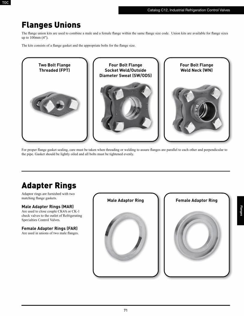
TOC
Catalog C12, Industrial Refrigeration Control Valves
71
Fla
ng
es
Two Bolt FlangeThreaded (FPT)
Four Bolt FlangeSocket Weld/Outside
Diameter Sweat (SW/ODS)
Four Bolt FlangeWeld Neck (WN)
Flanges Unions
up to 100mm (4”).
Adapter RingsAdaptor rings are furnished with two
Male Adapter Rings (MAR)
Specialties Control Valves.
Female Adapter Rings (FAR)
Male Adaptor Ring Female Adaptor Ring
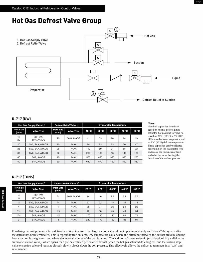
TOC
Catalog C12, Industrial Refrigeration Control Valves
72
Ho
t Ga
s D
efro
st
Hot Gas Defrost Valve Group
Evaporator
S
Hot Gas
Suction
Liquid
Defrost Relief to Suction
S
S
S
1
2
1. Hot Gas Supply Valve
2. Defrost Relief Valve
R-717 (KW)
Hot Gas Supply Valve 1 Defrost Relief Valve 2 Evaporator Temperature
Port Size
(mm)Valve Type
Port Size
(mm)Valve Type -10 ºC -20 ºC -30 ºC -40 ºC -50 ºC
1320
S8F, SV250% A4AOS
20 50% A4AOS 41 33 28 24 19
20 SV2, S4A, A4AOS 20 A4AK 78 73 63 56 47
25 SV2, S4A, A4AOS 25 A4AK 110 89 91 85 72
32 SV2, S4A, A4AOS 32 A4AK 210 190 16 140 120
40 S4A, A4AOS 40 A4AK 500 430 390 320 260
50 S4A, A4AOS 50 A4AK 640 570 460 390 330
R-717 (TONS)
Hot Gas Supply Valve 1 Defrost Relief Valve 2 Evaporator Temperature
Port Size
(inch)Valve Type
Port Size
(inch)Valve Type 20 ºF 0 ºF -20 ºF -40 ºF -60 ºF
1 ⁄23 ⁄4
S8F, SV250% A4AOS
3⁄4 50% A4AOS 14 10 7.9 6.7 5.2
3 ⁄4 SV2, S4A, A4AOS 3⁄4 A4AK 27 22 18 16 13
1 SV2, S4A, A4AOS 1 A4AK 38 27 26 24 20
11⁄4 SV2, S4A, A4AOS 11⁄4 A4AK 72 56 45 40 34
15 ⁄8 S4A, A4AOS 15 ⁄8 A4AK 170 130 110 90 72
2 S4A, A4AOS 2 A4AK 220 170 130 110 91
the defrost has been terminated. This is especially true on large, low temperature coils, where the difference between the defrost pressure and the house suction is the greatest, and where the internal volume of the coil is largest. The addition of a vent solenoid (usually piped in parallel to the automatic suction valve), which opens for a pre-determined period after defrost (when the hot gas solenoid de-energizes, and the suction stop valve or suction solenoid remains closed), slowly bleeds down the coil pressure. This effectively allows the defrost to terminate in a “soft” and safe manner.
Notes:
based on normal defrost times saturated hot gas inlet to valve no
difference between evaporator, and an 8°C (47°F) defrost temperature.
depending on the evaporator type
and other factors affecting the duration of the defrost process.
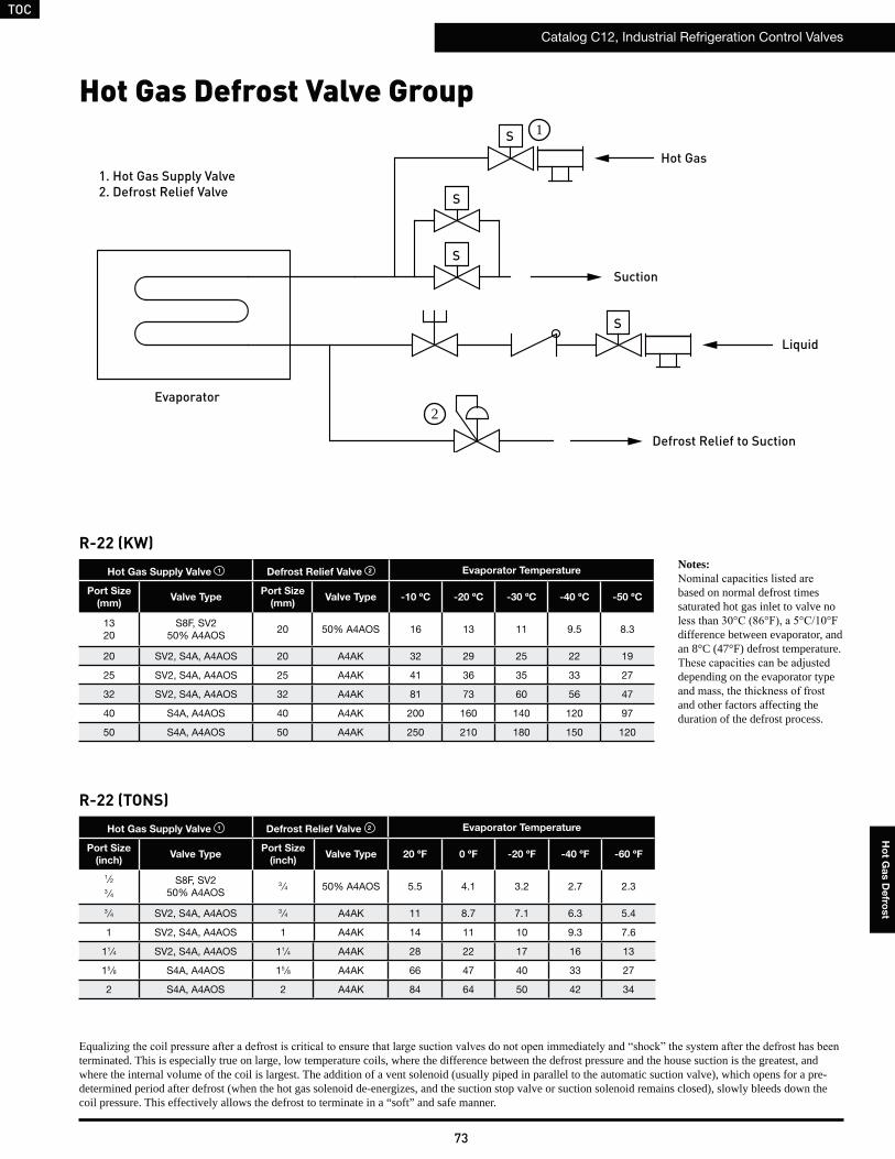
TOC
Catalog C12, Industrial Refrigeration Control Valves
73
Ho
t Ga
s D
efro
st
Hot Gas Defrost Valve Group
terminated. This is especially true on large, low temperature coils, where the difference between the defrost pressure and the house suction is the greatest, and where the internal volume of the coil is largest. The addition of a vent solenoid (usually piped in parallel to the automatic suction valve), which opens for a pre-determined period after defrost (when the hot gas solenoid de-energizes, and the suction stop valve or suction solenoid remains closed), slowly bleeds down the coil pressure. This effectively allows the defrost to terminate in a “soft” and safe manner.
Notes:
based on normal defrost times saturated hot gas inlet to valve no
difference between evaporator, and an 8°C (47°F) defrost temperature.
depending on the evaporator type
and other factors affecting the duration of the defrost process.
R-22 (KW)
Hot Gas Supply Valve 1 Defrost Relief Valve 2 Evaporator Temperature
Port Size
(mm)Valve Type
Port Size
(mm)Valve Type -10 ºC -20 ºC -30 ºC -40 ºC -50 ºC
1320
S8F, SV250% A4AOS
20 50% A4AOS 16 13 11 9.5 8.3
20 SV2, S4A, A4AOS 20 A4AK 32 29 25 22 19
25 SV2, S4A, A4AOS 25 A4AK 41 36 35 33 27
32 SV2, S4A, A4AOS 32 A4AK 81 73 60 56 47
40 S4A, A4AOS 40 A4AK 200 160 140 120 97
50 S4A, A4AOS 50 A4AK 250 210 180 150 120
R-22 (TONS)
Hot Gas Supply Valve 1 Defrost Relief Valve 2 Evaporator Temperature
Port Size
(inch)Valve Type
Port Size
(inch)Valve Type 20 ºF 0 ºF -20 ºF -40 ºF -60 ºF
1 ⁄23 ⁄4
S8F, SV250% A4AOS
3⁄4 50% A4AOS 5.5 4.1 3.2 2.7 2.3
3 ⁄4 SV2, S4A, A4AOS 3⁄4 A4AK 11 8.7 7.1 6.3 5.4
1 SV2, S4A, A4AOS 1 A4AK 14 11 10 9.3 7.6
11⁄4 SV2, S4A, A4AOS 11⁄4 A4AK 28 22 17 16 13
15 ⁄8 S4A, A4AOS 15 ⁄8 A4AK 66 47 40 33 27
2 S4A, A4AOS 2 A4AK 84 64 50 42 34
Evaporator
S
Hot Gas
Suction
Liquid
Defrost Relief to Suction
S
S
S
1
2
1. Hot Gas Supply Valve
2. Defrost Relief Valve
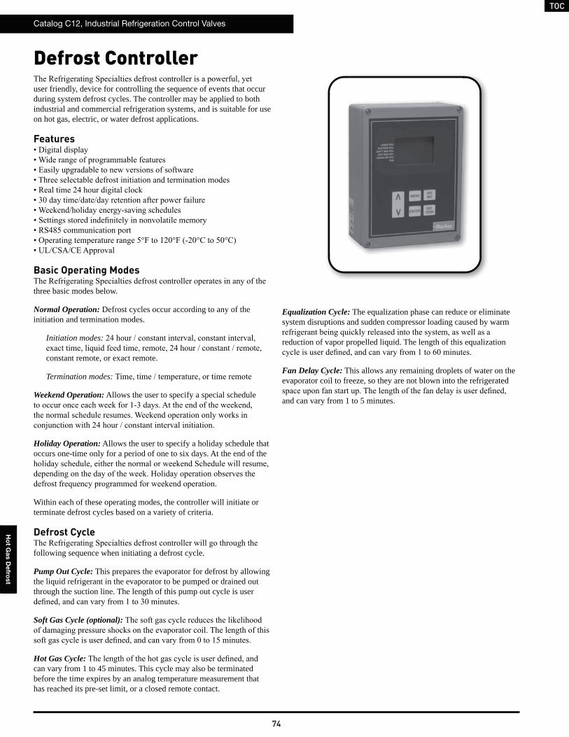
TOC
Catalog C12, Industrial Refrigeration Control Valves
74
Ho
t Ga
s D
efro
st
Defrost Controller
user friendly, device for controlling the sequence of events that occur during system defrost cycles. The controller may be applied to both industrial and commercial refrigeration systems, and is suitable for use on hot gas, electric, or water defrost applications.
Features
Basic Operating Modes
three basic modes below.
Normal Operation: Defrost cycles occur according to any of the initiation and termination modes.
Initiation modes:
constant remote, or exact remote.
Termination modes:
Weekend Operation: Allows the user to specify a special schedule
Holiday Operation: Allows the user to specify a holiday schedule that occurs one-time only for a period of one to six days. At the end of the
Within each of these operating modes, the controller will initiate or terminate defrost cycles based on a variety of criteria.
Defrost Cycle
following sequence when initiating a defrost cycle.
Pump Out Cycle: This prepares the evaporator for defrost by allowing the liquid refrigerant in the evaporator to be pumped or drained out through the suction line. The length of this pump out cycle is user
Soft Gas Cycle (optional):
Hot Gas Cycle:can vary from 1 to 45 minutes. This cycle may also be terminated before the time expires by an analog temperature measurement that has reached its pre-set limit, or a closed remote contact.
Equalization Cycle: The equalization phase can reduce or eliminate system disruptions and sudden compressor loading caused by warm
reduction of vapor propelled liquid. The length of this equalization
Fan Delay Cycle: This allows any remaining droplets of water on the evaporator coil to freeze, so they are not blown into the refrigerated
and can vary from 1 to 5 minutes.
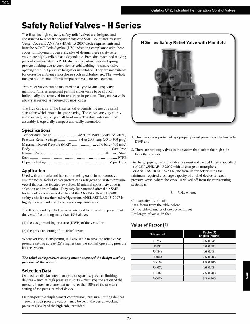
TOC
Catalog C12, Industrial Refrigeration Control Valves
75
SR
Vs
Safety Relief Valves - H Series
valves are highly reliable and dependable. Precision machined moving
opening at the set pressure long after installation. They are not suitable for corrosive ambient atmospheres such as chlorine, etc. The two-bolt
Two relief valves can be mounted on a Type M dual stop valve manifold. This arrangement permits either valve to be shut off individually and removed for repairs or inspection. Thus, one valve is always in service as required by most codes.
size valve which results in space saving. The valves are very sturdy and compact, requiring small headroom. The dual valve manifold assembly is especially compact and easily assembled.
Specifications
.......................... 27.6 barg (400 psig)
ApplicationUsed with ammonia and halocarbon refrigerants in noncorrosive
vessel that can be isolated by valves. Municipal codes may govern
highly recommended if there is no compulsory code.
the vessel from rising more than 10% above:
(2) the pressure setting of the relief device.
Whenever conditions permit, it is advisable to have the relief valve pressure setting at least 25% higher than the normal operating pressure for the system.
The relief valve pressure setting must not exceed the design working pressure of the vessel.
Selection DataOn positive displacement compressor systems, pressure limiting devices – such as high pressure cutouts – must stop the action of the pressure imposing element at no higher than 90% of the pressure setting of the pressure relief device.
On non-positive displacement compressors, pressure limiting devices
pressure (DWP) of the high side, provided:
1. The low side is protected bya properly sized pressure at the low side DWP and
2. There are not stop valves in the system that isolate the high side from the low side.
minimum required discharge capacity of a relief device for each pressure vessel where the vessel is valved off from the refrigerating systems is:
ƒ = a factor from the table belowD = outside diameter of the vessel in feet
Value of Factor (ƒ)
RefrigerantFactor (ƒ)
English (Metric)
R-717 0.5 (0.041)
R-22 1.6 (0.131)
R-134a 1.6 (0.131)
R-404a 2.5 (0.203)
R-410a 2.5 (0.203)
R-407c 1.6 (0.131)
R-502 2.5 (0.203)
R-507a 2.5 (0.203)
H Series Safety Relief Valve with Manifold
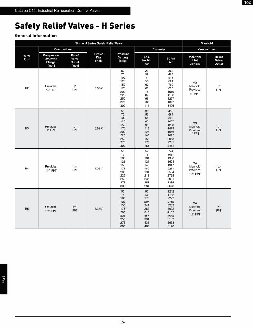
TOC
Catalog C12, Industrial Refrigeration Control Valves
76
SR
Vs
Safety Relief Valves - H SeriesGeneral Information
Single H Series Safety Relief Valve Manifold
Valve
Type
Connections
Orifice
Dia.
(inch)
Pressure
Setting
(psig)
Capacity Connections
Companion
Mounting
Flange
(inch)
Relief
Valve
Outlet
(inch)
Lbs.
Per Min
Air
SCFM
Air
Manifold
Inlet
Bottom
Relief
Valve
Outlet
H2Provides3 ⁄4” FPT
1”FPT
0.625”
5075
100125150175200225250275300
233241506069788796
105114
302422541661780899
10191138125713771496
M2Manifold Provides3 ⁄4” FPT
1”FPT
H3Provides1” FPT
11⁄4”FPT
0.825”
5075
100125150175200225250275300
3853688398
113128143158173188
498694890
10871283147916761872206822652461
M3ManifoldProvides1” FPT
11⁄4”FPT
H4Provides11⁄4” FPT
11⁄2”FPT
1.031”
5075
100125150175200225250275300
5779
101124146169191213236258281
7441037133016241917221125042798309133853678
M4ManifoldProvides11⁄2” FPT
11⁄2”FPT
H5Provides11⁄4” FPT
2”FPT
1.375”
5075
100125150175200225250275300
95132170207244282319357394431469
12421732222227123202369241824672516256536143
M4ManifoldProvides11⁄2” FPT
2”FPT
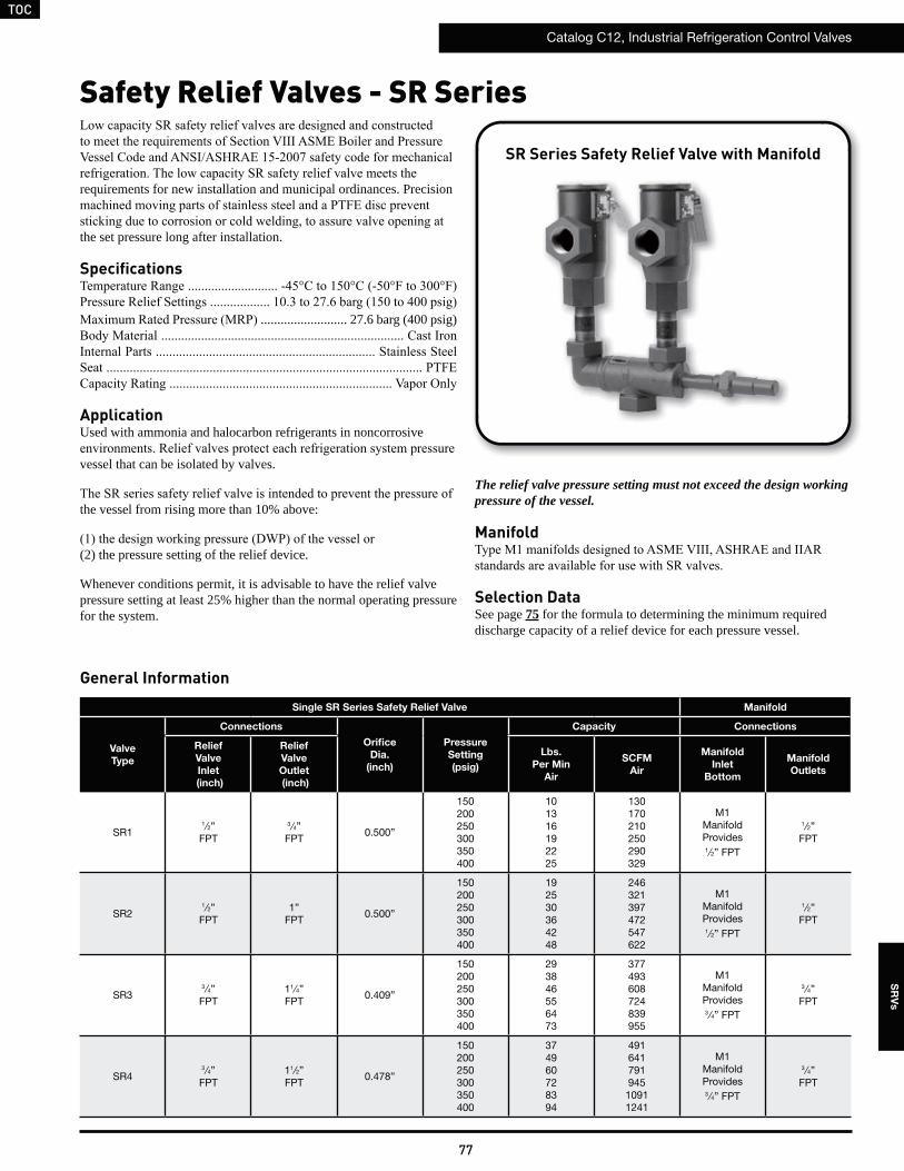
TOC
Catalog C12, Industrial Refrigeration Control Valves
77
SR
Vs
Safety Relief Valves - SR Series
General Information
Single SR Series Safety Relief Valve Manifold
Valve
Type
Connections
Orifice
Dia.
(inch)
Pressure
Setting
(psig)
Capacity Connections
Relief
Valve
Inlet
(inch)
Relief
Valve
Outlet
(inch)
Lbs.
Per Min
Air
SCFM
Air
Manifold
Inlet
Bottom
Manifold
Outlets
SR11⁄2”FPT
3 ⁄4”FPT
0.500”
150200250300350400
101316192225
130170210250290329
M1Manifold Provides1⁄2” FPT
1⁄2”FPT
SR21⁄2”FPT
1”FPT
0.500”
150200250300350400
192530364248
246321397472547622
M1ManifoldProvides1⁄2” FPT
1⁄2”FPT
SR33 ⁄4”FPT
11⁄4”FPT
0.409”
150200250300350400
293846556473
377493608724839955
M1ManifoldProvides3 ⁄4” FPT
3 ⁄4”FPT
SR43 ⁄4”FPT
11⁄2”FPT
0.478”
150200250300350400
374960728394
491641791945
10911241
M1ManifoldProvides3 ⁄4” FPT
3 ⁄4”FPT
requirements for new installation and municipal ordinances. Precision
the set pressure long after installation.
Specifications
.......................... 27.6 barg (400 psig)
ApplicationUsed with ammonia and halocarbon refrigerants in noncorrosive
vessel that can be isolated by valves.
the vessel from rising more than 10% above:
(2) the pressure setting of the relief device.
Whenever conditions permit, it is advisable to have the relief valve pressure setting at least 25% higher than the normal operating pressure for the system.
The relief valve pressure setting must not exceed the design working pressure of the vessel.
Manifold
Selection DataSee page 75 for the formula to determining the minimum required discharge capacity of a relief device for each pressure vessel.
SR Series Safety Relief Valve with Manifold
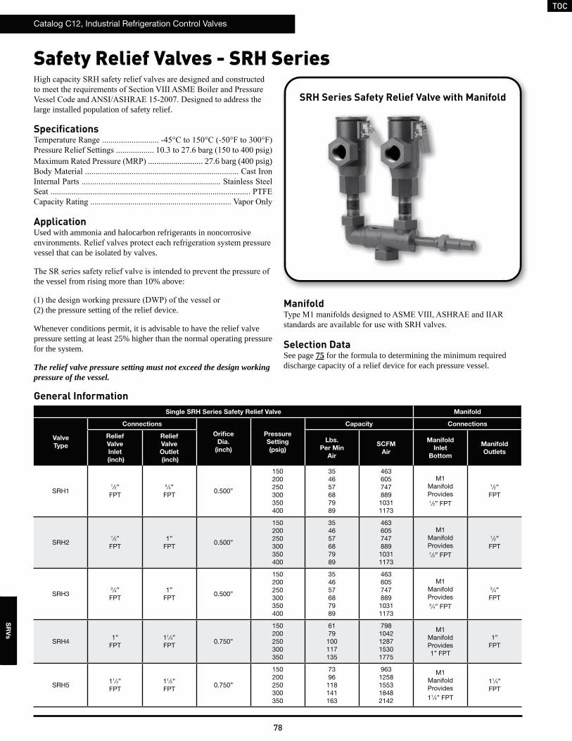
TOC
Catalog C12, Industrial Refrigeration Control Valves
78
SR
Vs
Safety Relief Valves - SRH Series
General InformationSingle SRH Series Safety Relief Valve Manifold
Valve
Type
Connections
Orifice
Dia.
(inch)
Pressure
Setting
(psig)
Capacity Connections
Relief
Valve
Inlet
(inch)
Relief
Valve
Outlet
(inch)
Lbs.
Per Min
Air
SCFM
Air
Manifold
Inlet
Bottom
Manifold
Outlets
SRH11⁄2”FPT
3 ⁄4”FPT
0.500”
150200250300350400
354657687989
463605747889
10311173
M1Manifold Provides1⁄2” FPT
1⁄2”FPT
SRH21⁄2”FPT
1”FPT
0.500”
150200250300350400
354657687989
463605747889
10311173
M1ManifoldProvides1⁄2” FPT
1⁄2”FPT
SRH33 ⁄4”FPT
1”FPT
0.500”
150200250300350400
354657687989
463605747889
10311173
M1ManifoldProvides3 ⁄4” FPT
3 ⁄4”FPT
SRH41”
FPT11⁄4”FPT
0.750”
150200250300350
6179
100117135
7981042128715301775
M1ManifoldProvides1” FPT
1”FPT
SRH511⁄4”FPT
11⁄2”FPT
0.750”
150200250300350
7396
118141163
9631258155318482142
M1ManifoldProvides11⁄4” FPT
11⁄4”FPT
large installed population of safety relief.
Specifications
.......................... 27.6 barg (400 psig)
ApplicationUsed with ammonia and halocarbon refrigerants in noncorrosive
vessel that can be isolated by valves.
the vessel from rising more than 10% above:
(2) the pressure setting of the relief device.
Whenever conditions permit, it is advisable to have the relief valve pressure setting at least 25% higher than the normal operating pressure for the system.
The relief valve pressure setting must not exceed the design working pressure of the vessel.
SRH Series Safety Relief Valve with Manifold
Manifold
Selection DataSee page 75 for the formula to determining the minimum required discharge capacity of a relief device for each pressure vessel.
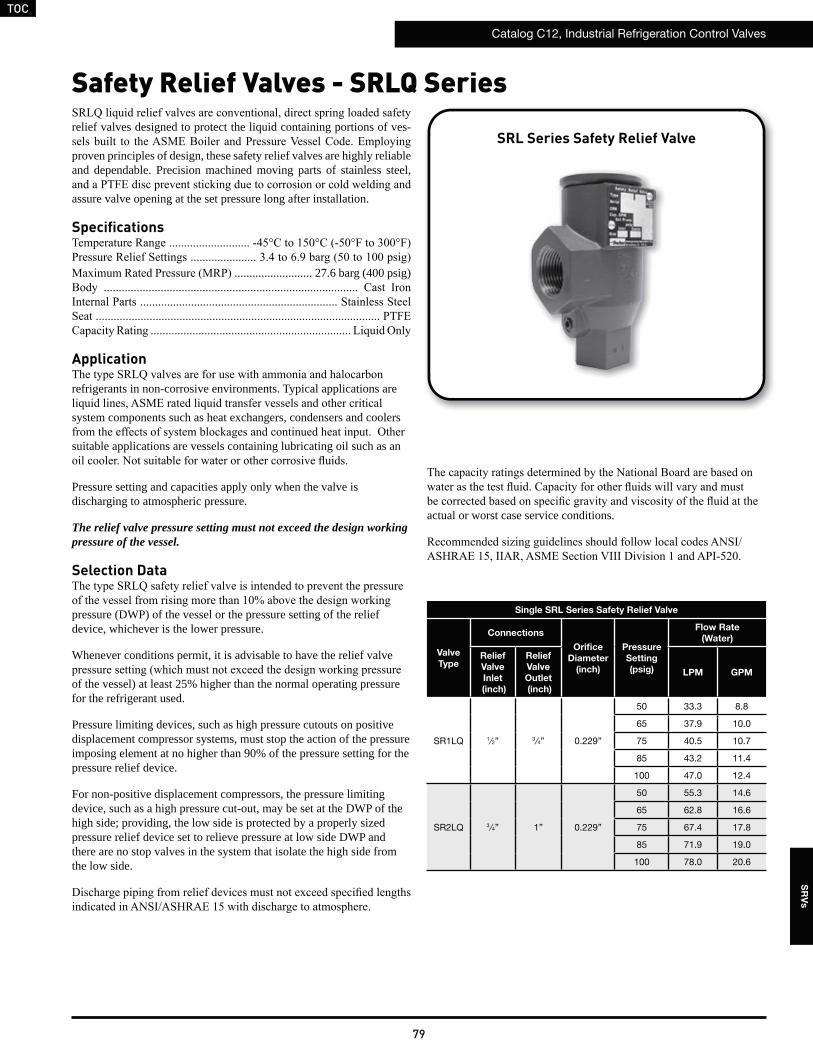
TOC
Catalog C12, Industrial Refrigeration Control Valves
79
SR
Vs
Safety Relief Valves - SRLQ Series
relief valves designed to protect the liquid containing portions of ves-
proven principles of design, these safety relief valves are highly reliable and dependable. Precision machined moving parts of stainless steel,
assure valve opening at the set pressure long after installation.
Specifications
.......................... 27.6 barg (400 psig)
Application
refrigerants in non-corrosive environments. Typical applications are
system components such as heat exchangers, condensers and coolers
suitable applications are vessels containing lubricating oil such as an
Pressure setting and capacities apply only when the valve is discharging to atmospheric pressure.
The relief valve pressure setting must not exceed the design working pressure of the vessel.
Selection Data
pressure (DWP) of the vessel or the pressure setting of the relief device, whichever is the lower pressure.
Whenever conditions permit, it is advisable to have the relief valve
of the vessel) at least 25% higher than the normal operating pressure for the refrigerant used.
Pressure limiting devices, such as high pressure cutouts on positive displacement compressor systems, must stop the action of the pressure imposing element at no higher than 90% of the pressure setting for the pressure relief device.
For non-positive displacement compressors, the pressure limiting device, such as a high pressure cut-out, may be set at the DWP of the high side; providing, the low side is protected by a properly sized pressure relief device set to relieve pressure at low side DWP and there are no stop valves in the system that isolate the high side from the low side.
actual or worst case service conditions.
SRL Series Safety Relief Valve
Single SRL Series Safety Relief Valve
Valve
Type
Connections
Orifice
Diameter
(inch)
Pressure
Setting
(psig)
Flow Rate
(Water)
Relief
Valve
Inlet
(inch)
Relief
Valve
Outlet
(inch)
LPM GPM
SR1LQ 1⁄2” 3 ⁄4” 0.229”
50 33.3 8.8
65 37.9 10.0
75 40.5 10.7
85 43.2 11.4
100 47.0 12.4
SR2LQ 3⁄4” 1” 0.229”
50 55.3 14.6
65 62.8 16.6
75 67.4 17.8
85 71.9 19.0
100 78.0 20.6
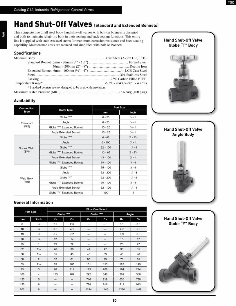
TOCTOC
Catalog C12, Industrial Refrigeration Control Valves
80
HV
s
Catalog C12, Industrial Refrigeration Control Valves
80
Hand Shut-Off Valves (Standard and Extended Bonnets)
Port SizeFlow Coefficient
Globe “T” Globe “Y” Angle
mm inch Kv Cv Kv Cv Kv Cv
6 1⁄4 2.2 2.6 — — 3.1 3.6
10 3 ⁄8 3.5 4.1 — — 4.7 5.5
13 1⁄2 6.2 7.2 — — 6.9 8.0
20 3 ⁄4 12 14 — — 15 17
25 1 19 22 — — 23 27
32 11⁄4 26 30 41 47 30 35
38 11⁄2 35 43 46 53 40 46
50 2 52 61 80 93 73 85
65 21⁄2 89 103 131 153 128 149
75 3 98 114 179 208 184 214
100 4 173 202 292 340 301 350
125 5 — — 716 718 635 739
150 6 — — 788 916 811 943
200 8 — — 1244 1446 1280 1489
General Information
Hand Shut-Off ValveGlobe “T” Body
Hand Shut-Off ValveAngle Body
Hand Shut-Off ValveGlobe “Y” Body
Connection
TypeBody Type
Port Size
mm Inch
Threaded(FPT)
Globe “T” 6 - 25 1⁄4 -1
Angle 6 - 25 1⁄4 -1
Globe “T” Extended Bonnet 13 - 25 1⁄2 -1
Angle Extended Bonnet 13 - 25 1⁄2 -1
Socket Weld(SW)
Globe “T” 6 - 65 1⁄4 - 21⁄2
Angle 6 - 100 1⁄4 - 4
Globe “Y” 32 - 100 11⁄4 - 4
Globe “T” Extended Bonnet 13 - 65 1⁄2 - 21⁄2
Angle Extended Bonnet 13 - 100 1⁄2 - 4
Globe “Y” Extended Bonnet 75 - 100 3 - 4
Weld Neck(WN)
Globe “T” 75 - 100 3 - 4
Angle 32 - 200 11⁄4 - 8
Globe “Y” 32 - 200 11⁄4 - 8
Globe “T” Extended Bonnet 75 - 100 3 - 4
Angle Extended Bonnet 32 - 100 11⁄4 - 4
Globe “Y” Extended Bonnet 100 4
Availability
This complete line of all steel body hand shut-off valves with bolt-on bonnets is designed
SpecificationsMaterial: Body ...........................
Standard Bonnet: 6mm - 38mm (1 4” - 11 2”) ............................................. Forged Steel
1 4
Stem ................................................................................................ 304 Stainless Steel
* Standard bonnets are not designed to be used with insolation.......................................................... 27.6 barg (400 psig)
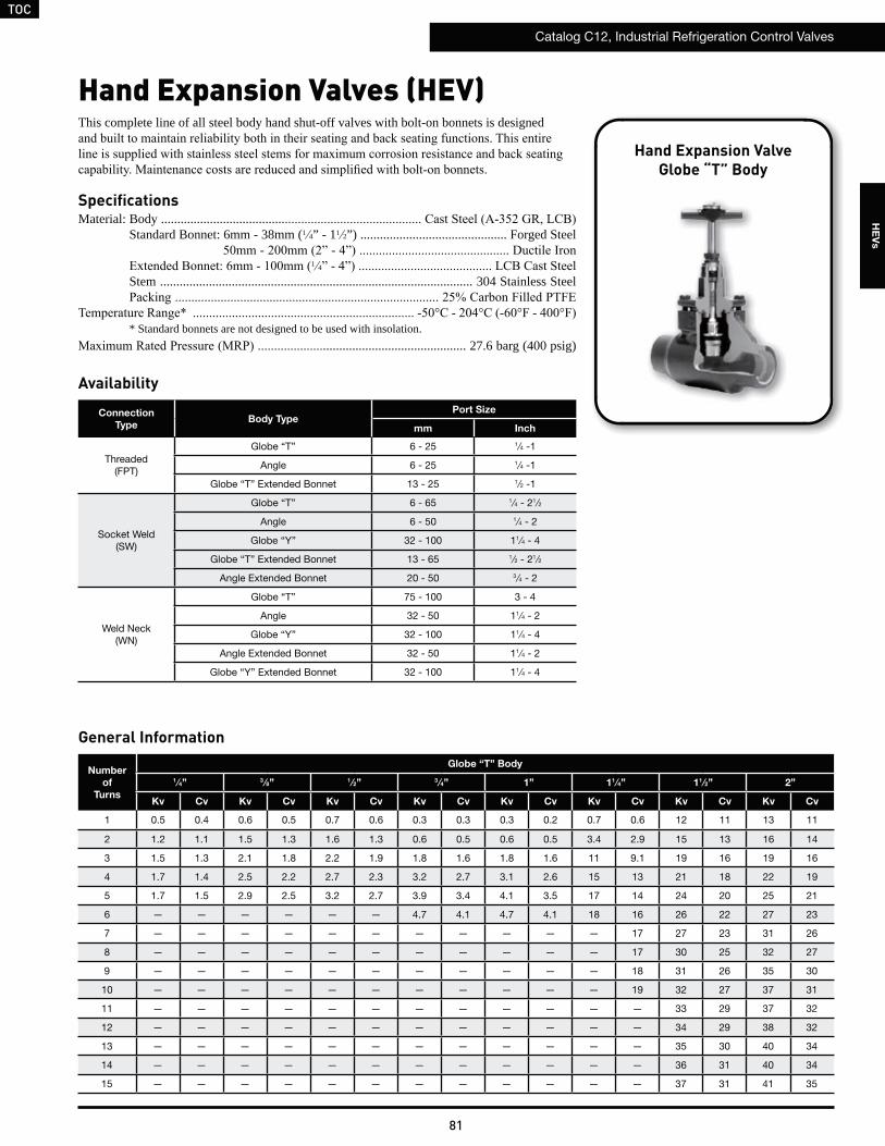
TOC
Catalog C12, Industrial Refrigeration Control Valves
81
HE
Vs
Hand Expansion Valves (HEV)
Hand Expansion ValveGlobe “T” Body
Number
of
Turns
Globe “T” Body
1⁄4” 3 ⁄8” 1 ⁄2” 3 ⁄4” 1” 11 ⁄4” 11 ⁄2” 2”
Kv Cv Kv Cv Kv Cv Kv Cv Kv Cv Kv Cv Kv Cv Kv Cv
1 0.5 0.4 0.6 0.5 0.7 0.6 0.3 0.3 0.3 0.2 0.7 0.6 12 11 13 11
2 1.2 1.1 1.5 1.3 1.6 1.3 0.6 0.5 0.6 0.5 3.4 2.9 15 13 16 14
3 1.5 1.3 2.1 1.8 2.2 1.9 1.8 1.6 1.8 1.6 11 9.1 19 16 19 16
4 1.7 1.4 2.5 2.2 2.7 2.3 3.2 2.7 3.1 2.6 15 13 21 18 22 19
5 1.7 1.5 2.9 2.5 3.2 2.7 3.9 3.4 4.1 3.5 17 14 24 20 25 21
6 — — — — — — 4.7 4.1 4.7 4.1 18 16 26 22 27 23
7 — — — — — — — — — — — 17 27 23 31 26
8 — — — — — — — — — — — 17 30 25 32 27
9 — — — — — — — — — — — 18 31 26 35 30
10 — — — — — — — — — — — 19 32 27 37 31
11 — — — — — — — — — — — — 33 29 37 32
12 — — — — — — — — — — — — 34 29 38 32
13 — — — — — — — — — — — — 35 30 40 34
14 — — — — — — — — — — — — 36 31 40 34
15 — — — — — — — — — — — — 37 31 41 35
General Information
Connection
TypeBody Type
Port Size
mm Inch
Threaded(FPT)
Globe “T” 6 - 25 1⁄4 -1
Angle 6 - 25 1⁄4 -1
Globe “T” Extended Bonnet 13 - 25 1⁄2 -1
Socket Weld(SW)
Globe “T” 6 - 65 1⁄4 - 21⁄2
Angle 6 - 50 1⁄4 - 2
Globe “Y” 32 - 100 11⁄4 - 4
Globe “T” Extended Bonnet 13 - 65 1⁄2 - 21⁄2
Angle Extended Bonnet 20 - 50 3 ⁄4 - 2
Weld Neck(WN)
Globe “T” 75 - 100 3 - 4
Angle 32 - 50 11⁄4 - 2
Globe “Y” 32 - 100 11⁄4 - 4
Angle Extended Bonnet 32 - 50 11⁄4 - 2
Globe “Y” Extended Bonnet 32 - 100 11⁄4 - 4
Availability
This complete line of all steel body hand shut-off valves with bolt-on bonnets is designed
SpecificationsMaterial: Body ......................................
Standard Bonnet: 6mm - 38mm (1 4” - 11 2”) ............................................. Forged Steel
1 4
Stem ................................................................................................ 304 Stainless Steel
* Standard bonnets are not designed to be used with insolation............................................. 27.6 barg (400 psig)
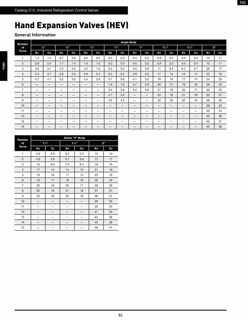
TOC
Catalog C12, Industrial Refrigeration Control Valves
82
HE
Vs
Hand Expansion Valves (HEV)
Number
of
Turns
Angle Body
1⁄4” 3 ⁄8” 1 ⁄2” 3 ⁄4” 1” 11 ⁄4” 11 ⁄2” 2”
Kv Cv Kv Cv Kv Cv Kv Cv Kv Cv Kv Cv Kv Cv Kv Cv
1 1.4 1.2 0.7 0.6 0.5 0.5 0.3 0.3 0.3 0.3 0.8 0.7 0.4 0.3 13 11
2 2.8 2.4 1.7 1.4 1.5 1.3 0.3 0.3 0.6 0.5 3.9 3.3 0.5 0.5 13 11
3 3.6 3.1 2.3 2.0 2.2 1.9 0.3 0.3 0.9 0.8 11 9.4 6.7 5.7 20 17
4 4.3 3.7 2.8 2.4 2.8 2.4 0.3 0.3 2.9 2.5 17 14 13 11 22 18
5 4.7 4.1 3.5 3.0 3.4 2.9 0.7 0.6 4.1 3.5 18 16 17 14 24 20
6 — — — — — — 1.9 1.6 4.7 4.0 20 17 19 16 26 23
7 — — — — — — 3.0 2.6 5.4 4.6 21 18 20 17 30 25
8 — — — — — — 4.1 3.5 — — 22 18 21 18 32 27
9 — — — — — — 4.9 4.2 — — 23 20 22 19 36 30
10 — — — — — — — — — — — — — — 38 33
11 — — — — — — — — — — — — — — 40 34
12 — — — — — — — — — — — — — — 42 36
13 — — — — — — — — — — — — — — 43 37
14 — — — — — — — — — — — — — — 45 39
General Information
Number
of
Turns
Globe “Y” Body
11⁄4” 11 ⁄2” 2”
Kv Cv Kv Cv Kv Cv
1 0.6 0.5 0.4 0.3 12 10
2 3.0 2.6 0.7 0.6 13 11
3 10 9.0 7.5 6.4 19 16
4 17 14 14 12 21 18
5 18 16 17 15 23 19
6 19 17 19 16 26 22
7 20 18 20 17 30 26
8 22 19 21 18 31 27
9 23 20 22 19 36 31
10 — — — — 39 33
11 — — — — 39 34
12 — — — — 41 35
13 — — — — 44 38
14 — — — — 45 38
15 — — — — 48 41

TOC
Catalog C12, Industrial Refrigeration Control Valves
83
HE
Vs
R-717 (KW)
Port
Size
Pressure
Drop
(bar)
Number of Turns
1 2 3 4 5 6 7 8 9 10 11 12 13 14 15
6mm
0.340.691.031.382.07
1522263037
3955677895
47678294115
517389103126
547693107131
— — — — — — — — — —
10mm
0.340.691.031.382.07
1927333846
47678294115
6693114132162
78111136157192
91128157181222
— — — — — — — — — —
13mm
0.340.691.031.382.07
2029354150
49698497119
7098121139171
84119146168206
99140172199243
— — — — — — — — — —
20mm
0.340.691.031.382.07
1115182126
1725303543
578098113139
98138170196240
122173212244299
147208254294360
— — — — — — — — —
25mm
0.340.691.031.382.07
8.712151721
1825313644
578199115140
95134165190233
128180221255313
147208255294361
— — — — — — — — —
32mm
0.340.691.031.382.07
2232394555
104148181209256
328465569657805
4766738249511165
51873389810371270
563796975
11261379
605856
104912111483
617873
106912341512
661935
114513231620
686971
118913731681
— — — — —
40mm
0.340.691.031.382.07
383542664766939
4726688189451157
580821100511611422
660933114213191615
7361041127514721803
8031135139016051966
8451195146316902069
9221304159818452259
9581355165919162346
9801386169819612401
10341462179120682533
10621502184021252602
10961550189821912684
11171579193422332735
11361606196722712782
50mm
0.340.691.031.382.07
394558683789966
50871887910151243
578817100111561416
682964118113631670
7701089133315391885
8431192145916852064
9461337163818912316
9871396171019752418
10921544189121842675
11371608196922742785
11491625199022982814
11741661203423492877
12261734212324523003
12351746213924703025
12741801220625473120
density and laten heat variations.
A recirculation rate of 4:1 was used to calculate the capacity tables. For other recirculation rates, divide 4 by the new recirculation rate and multiply values shown in table to arrive at new capacity.
n:1 4:1
3:1
3:1
Liquid Overfeed Capacities - Globe “T” Body
4
43

TOC
Catalog C12, Industrial Refrigeration Control Valves
84
HE
Vs
R-717 (TONS)
density and laten heat variations.
A recirculation rate of 4:1 was used to calculate the capacity tables. For other recirculation rates, divide 4 by the new recirculation rate and multiply values shown in table to arrive at new capacity.
Port
Size
Pressure
Drop
(psi)
Number of Turns
1 2 3 4 5 6 7 8 9 10 11 12 13 14 15
1 ⁄4”
510152030
4.46.27.58.711
1116192227
1319232733
1521262936
1522273138
— — — — — — — — — —
3⁄8”
510152030
5.47.69.31113
1319232733
1927333846
2232394555
2637455264
— — — — — — — — — —
1⁄2”
510152030
5.88.2101214
1420242834
2028344049
2434424859
2840495770
— — — — — — — — — —
3⁄4”
510152030
3.04.35.26.07.4
5.07.08.61012
1623283240
2840495669
3549617086
42597384
103
— — — — — — — — —
1”
510152030
2.53.54.35.06.1
5.17.28.81012
1623283340
2738475467
3752637389
42607384
103
— — — — — — — — —
11⁄4”
510152030
6.49.1111316
3042526073
94133163188230
136192236272333
148210257297363
161228279322395
173245300346424
177250306353432
189268328378463
196278340393481
— — — — —
11⁄2”
510152030
110155190219269
135191234270331
166235288332407
189267327377462
211298365421516
230325398459563
242342419483592
264373457528646
274388475548671
281397486561687
296418512592725
304430526608745
313443543627768
320452553639783
325459563650796
2”
510152030
113160195226276
145205252290356
165234286331405
195276338390478
220311381440539
241341418482591
271383469541663
282399489565692
312442541625765
325460563651797
329465569657805
336475582672823
351496607701859
353500612707865
364515631729893
Liquid Overfeed Capacities - Globe “T” Body
n:1 4:1 (Tons)
3:1
3:1 = 37 Tons
4
43

TOC
Catalog C12, Industrial Refrigeration Control Valves
85
HE
Vs
R-22 (KW)
Port
Size
Pressure
Drop
(bar)
Number of Turns
1 2 3 4 5 6 7 8 9 10 11 12 13 14 15
6mm
0.340.691.031.382.07
3.55.06.17.18.6
9.013161822
1115192227
1217212429
1218222530
— — — — — — — — — —
10mm
0.340.691.031.382.07
4.46.27.68.711
1115192227
1522263137
1826313644
2130364251
— — — — — — — — — —
13mm
0.340.691.031.382.07
4.76.78.19.412
1116192328
1623283239
1928343948
2333404656
— — — — — — — — — —
20mm
0.340.691.031.382.07
2.43.44.24.96.0
4.05.77.08.19.9
1319232632
2332394556
2840495769
3448596883
— — — — — — — — —
25mm
0.340.691.031.382.07
2.02.93.54.04.9
4.15.87.18.210
1319232733
2231384454
3042515972
3448596884
— — — — — — — — —
32mm
0.340.691.031.382.07
5.27.49.01013
2434424859
76108132152186
110156191220270
120170208240294
130184226261319
140198243280344
143202248286350
153217265306375
159225275318389
— — — — —
40mm
0.340.691.031.382.07
89126154178217
109155190219268
134190233269329
153216265306374
170241295341418
186263322372455
196277339391479
214302370427523
222314384444543
227321393454556
240339415479587
246348426492603
254359440508622
259366448517634
263372456526644
50mm
0.340.691.031.382.07
91129158183224
118166204235288
134189232268328
158223273316387
178252309357437
195276338390478
219310379438536
229323396457560
253358438506620
263372456527645
266376461532652
272385471544666
284402492568696
286405495572701
295417511590723
density and laten heat variations.
A recirculation rate of 4:1 was used to calculate the capacity tables. For other recirculation rates, divide 4 by the new recirculation rate and multiply values shown in table to arrive at new capacity.
Liquid Overfeed Capacities - Globe “T” Body
n:1 4:1
3:1
3:1
4
43

TOC
Catalog C12, Industrial Refrigeration Control Valves
86
HE
Vs
R-22 (TONS)
Port
Size
Pressure
Drop
(psi)
Number of Turns
1 2 3 4 5 6 7 8 9 10 11 12 13 14 15
1 ⁄4”
510152030
1.01.41.82.02.5
2.63.64.55.26.3
3.14.45.46.37.7
3.44.85.96.88.4
3.65.06.27.18.7
— — — — — — — — — —
3⁄8”
510152030
1.31.82.22.53.1
3.14.45.46.37.7
4.46.27.68.811
5.27.49.01013
6.08.5101215
— — — — — — — — — —
1⁄2”
510152030
1.31.92.32.73.3
3.24.65.66.57.9
4.66.58.0911
5.67.99.71114
6.69.3111316
— — — — — — — — — —
3⁄4”
510152030
0.71.01.21.41.7
1.21.62.02.32.8
3.85.36.57.59.2
6.59.2111316
8.111141620
9.814172024
— — — — — — — — —
1”
510152030
0.60.81.01.21.4
1.21.72.02.42.9
3.85.46.67.69.3
6.38.9111315
8.512151721
9.814172024
— — — — — — — — —
11⁄4”
510152030
1.52.12.63.03.7
6.99.8121417
2231384453
3245556377
3449606984
3753657592
4057708098
41587182
100
44627688
108
46647991
112
— — — — —
11⁄2”
510152030
2536445162
3144546377
3955677794
44627688107
49698598120
537592
107131
567997
112137
6187
106123150
6490
110127156
6592
113130159
6997
119137168
71100122141173
73103126146178
74105128148182
75107131151185
2”
510152030
2637455264
3448586783
3854667794
45647891111
517289102125
567997
112137
6389
109126154
6693
114131161
73103126145178
76107131151185
76108132153187
78110135156191
81115141163199
82116142164201
85120147169207
Liquid Overfeed Capacities - Globe “T” Body
density and laten heat variations.
A recirculation rate of 4:1 was used to calculate the capacity tables. For other recirculation rates, divide 4 by the new recirculation rate and multiply values shown in table to arrive at new capacity.
n:1 4:1 (Tons)
3:1
3:1 = 8.8 Tons
4
43

TOC
Catalog C12, Industrial Refrigeration Control Valves
87
HE
Vs
R-134a (KW)
Port
Size
Pressure
Drop
(bar)
Number of Turns
1 2 3 4 5 6 7 8 9 10 11 12 13 14 15
6mm
0.340.691.031.382.07
3.44.95.96.98.4
8.712151721
1115182126
1216202328
1217212430
— — — — — — — — — —
10mm
0.340.691.031.382.07
4.26.07.48.510
1115182126
1521263036
1825313543
2029354150
— — — — — — — — — —
13mm
0.340.691.031.382.07
4.66.57.99.211
1115192227
1622273138
1927333846
2232394555
— — — — — — — — — —
20mm
0.340.691.031.382.07
2.43.44.14.75.8
3.95.56.87.89.6
1318222531
2231384454
2839485567
3347576681
— — — — — — — — —
25mm
0.340.691.031.382.07
2.02.83.43.94.8
4.05.76.98.09.8
1318222632
2130374352
2941505870
3347576681
— — — — — — — — —
32mm
0.340.691.031.382.07
5.17.28.81012
2433414758
74105128148181
107152186214263
117165202234286
127179220254311
136193236273334
139197241278341
149211258298365
155219268309379
— — — — —
40mm
0.340.691.031.382.07
86122150173212
106151184213261
131185227262320
149210257297364
166235287332406
181256313362443
190269330381466
208294360416509
216305374432529
221312383442541
233330404466571
239339415479586
247349428494605
252356436503616
256362443512627
50mm
0.340.691.031.382.07
89126154178218
114162198229280
130184226260319
154217266307376
173245300347425
190269329380465
213301369426522
222315385445545
246348426492603
256362444512628
259366448518634
265374458529648
276391478553677
278394482557682
287406497574703
density and laten heat variations.
A recirculation rate of 4:1 was used to calculate the capacity tables. For other recirculation rates, divide 4 by the new recirculation rate and multiply values shown in table to arrive at new capacity.
Liquid Overfeed Capacities - Globe “T” Body
n:1 4:1
3:1
3:1
4
43

TOC
Catalog C12, Industrial Refrigeration Control Valves
88
HE
Vs
R-134a (TONS)
Port
Size
Pressure
Drop
(psi)
Number of Turns
1 2 3 4 5 6 7 8 9 10 11 12 13 14 15
1 ⁄4”
510152030
1.01.41.72.02.4
2.53.54.35.06.1
3.04.35.36.17.5
3.34.75.86.78.1
3.54.96.06.98.5
— — — — — — — — — —
3⁄8”
510152030
1.21.72.12.43.0
3.04.35.36.17.5
4.36.07.48.510
5.17.28.81012
5.98.3101214
— — — — — — — — — —
1⁄2”
510152030
1.31.92.32.63.2
3.14.45.46.37.7
4.56.47.89.011
5.47.79.41113
6.49.1111316
— — — — — — — — — —
3⁄4”
510152030
0.71.01.21.41.7
1.11.61.92.22.8
3.75.26.37.39.0
6.38.9111315
7.911141619
9.513161923
— — — — — — — — —
1”
510152030
0.60.81.01.11.4
1.11.62.02.32.8
3.75.26.47.49.1
6.18.7111215
8.212141620
9.513161923
— — — — — — — — —
11⁄4”
510152030
1.52.12.52.93.6
6.79.5121317
2130374252
3143536175
3347586782
3651637389
3955687896
4056698098
43607485
105
44637789
109
— — — — —
11⁄2”
510152030
2535435061
3143536175
3753657592
43607485104
48678295116
527390
104127
557795
109134
6084
103119146
6288
107124152
6390
110127155
6794
116134164
6997
119137168
71100123142173
72102125144177
73104127147180
2”
510152030
2536445162
3346576680
3753657591
44627688108
50708699122
547794
109133
6186
106122150
6490
110128156
71100122141173
73104127147180
74105129148182
76107131152186
79112137158194
80113138160195
82116143165202
density and laten heat variations.
A recirculation rate of 4:1 was used to calculate the capacity tables. For other recirculation rates, divide 4 by the new recirculation rate and multiply values shown in table to arrive at new capacity.
Liquid Overfeed Capacities - Globe “T” Body
n:1 4:1 (Tons)
3:1
3:1 = 8.5 Tons
4
43

TOC
Catalog C12, Industrial Refrigeration Control Valves
89
HE
Vs
R-404a (KW)
Port
Size
Pressure
Drop
(bar)
Number of Turns
1 2 3 4 5 6 7 8 9 10 11 12 13 14 15
6mm
0.340.691.031.382.07
2.73.94.75.56.7
6.99.8121417
8.412151721
9.213161823
9.614171924
— — — — — — — — — —
10mm
0.340.691.031.382.07
3.44.85.86.78.3
8.412151721
1217202429
1420242834
1623283240
— — — — — — — — — —
13mm
0.340.691.031.382.07
3.65.16.37.38.9
8.712151721
1218222531
1521263037
1825313644
— — — — — — — — — —
20mm
0.340.691.031.382.07
1.92.73.33.84.6
3.14.45.46.27.6
1014182025
1825303543
2231384454
2637465364
— — — — — — — — —
25mm
0.340.691.031.382.07
1.62.22.73.13.8
3.24.55.56.47.8
1014182125
1724293442
2332404656
2637465365
— — — — — — — — —
32mm
0.340.691.031.382.07
4.05.77.08.09.9
1926323746
5983102118144
85120147170209
93131161186227
101143175202247
108153188217265
110156191221270
118167205237290
123174213246301
— — — — —
40mm
0.340.691.031.382.07
6997119137168
85120146169207
104147180208254
118167204236289
132186228263323
144203249287352
151214262302370
165233286330404
171242297343420
175248304351430
185262321370453
190269329380466
196277340392480
200283346400490
203287352406498
50mm
0.340.691.031.382.07
71100122141173
91128157182223
103146179207253
122173211244299
138195239275337
151213261302369
169239293338414
177250306353433
195276338391479
203288352407498
206291356411504
210297364420515
219310380439537
221313383442541
228322395456558
density and laten heat variations.
A recirculation rate of 4:1 was used to calculate the capacity tables. For other recirculation rates, divide 4 by the new recirculation rate and multiply values shown in table to arrive at new capacity.
Liquid Overfeed Capacities - Globe “T” Body
n:1 4:1
3:1
3:1
4
43

TOC
Catalog C12, Industrial Refrigeration Control Valves
90
HE
Vs
R-404a (TONS)
Port
Size
Pressure
Drop
(psi)
Number of Turns
1 2 3 4 5 6 7 8 9 10 11 12 13 14 15
1 ⁄4”
510152030
0.81.11.41.61.9
2.02.83.54.04.9
2.43.44.24.85.9
2.63.74.65.36.5
2.83.94.85.56.8
— — — — — — — — — —
3⁄8”
510152030
1.01.41.71.92.4
2.43.44.24.85.9
3.44.85.96.88.3
4.05.77.08.19.9
4.76.68.19.311
— — — — — — — — — —
1⁄2”
510152030
1.01.51.82.12.6
2.53.54.35.06.1
3.65.16.27.28.8
4.36.17.58.711
5.17.28.91013
— — — — — — — — — —
3⁄4”
510152030
0.50.80.91.11.3
0.91.31.61.82.2
2.94.15.05.87.1
5.07.18.71012
6.38.9111315
7.611131519
— — — — — — — — —
1”
510152030
0.40.60.80.91.1
0.91.31.61.82.2
2.94.25.15.97.2
4.96.98.59.812
6.69.3111316
7.611131519
— — — — — — — — —
11⁄4”
510152030
1.21.62.02.32.8
5.47.69.31113
1724293441
2435424960
2738465365
2941505871
3144546276
3245556378
3448596883
3550617186
— — — — —
11⁄2”
510152030
2028343948
2434424960
3042526073
3448596883
3854667693
41587283
101
43617587
106
47678295
116
49708599
121
507187
101124
537592
106130
557795
109134
568098
113138
578199
115141
5883101117143
2”
510152030
2029354150
2637455264
3042515973
3550617086
4056697997
43617587
106
49698497
119
517288
102124
567997
112138
5883
101117143
5984
102118145
6085
105121148
6389
109126154
6490
110127156
6693113131160
density and laten heat variations.
A recirculation rate of 4:1 was used to calculate the capacity tables. For other recirculation rates, divide 4 by the new recirculation rate and multiply values shown in table to arrive at new capacity.
Liquid Overfeed Capacities - Globe “T” Body
n:1 4:1 (Tons)
3:1
3:1 = 6.8 Tons
4
43
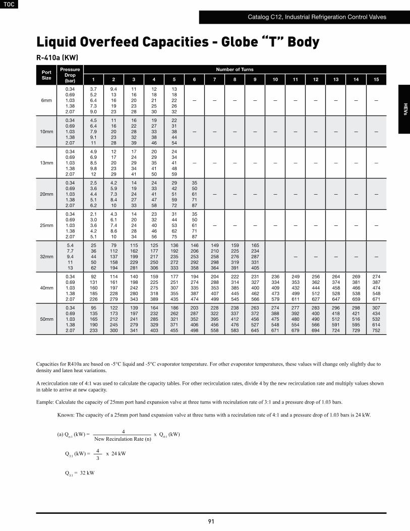
TOC
Catalog C12, Industrial Refrigeration Control Valves
91
HE
Vs
R-410a (KW)
Port
Size
Pressure
Drop
(bar)
Number of Turns
1 2 3 4 5 6 7 8 9 10 11 12 13 14 15
6mm
0.340.691.031.382.07
3.75.26.47.39.0
9.413161923
1116202328
1218212530
1318222632
— — — — — — — — — —
10mm
0.340.691.031.382.07
4.56.47.99.111
1116202328
1622283239
1927333846
2231384454
— — — — — — — — — —
13mm
0.340.691.031.382.07
4.96.98.59.812
1217202329
1724293441
2029354150
2434414859
— — — — — — — — — —
20mm
0.340.691.031.382.07
2.53.64.45.16.2
4.25.97.38.410
1419242733
2433414758
2942515972
3550617187
— — — — — — — — —
25mm
0.340.691.031.382.07
2.13.03.64.25.1
4.36.17.48.610
1420242834
2332404656
3144536275
3550617187
— — — — — — — — —
32mm
5.47.79.41113
2536445062
79112137158194
115162199229281
125177217250306
136192235272333
146206253292358
149210258298364
159225276319391
165234287331405
— — — — —
40mm
0.340.691.031.382.07
92131160185226
114161197228279
140198242280343
159225275318389
177251307355435
194274335387474
204288353407499
222314385445545
231327400462566
236334409473579
249353432499611
256362444512627
264374458528647
269381466538659
274387474548671
50mm
0.340.691.031.382.07
95135165190233
122173212245300
139197241279341
164232285329403
186262321371455
203287352406498
228322395456558
238337412476583
263372456527645
274388475548671
277392480554679
283400490566694
296418512591724
298421516595729
307434532614752
density and laten heat variations.
A recirculation rate of 4:1 was used to calculate the capacity tables. For other recirculation rates, divide 4 by the new recirculation rate and multiply values shown in table to arrive at new capacity.
Liquid Overfeed Capacities - Globe “T” Body
n:1 4:1
3:1
3:1
4
43

TOC
Catalog C12, Industrial Refrigeration Control Valves
92
HE
Vs
R-410a (TONS)
Port
Size
Pressure
Drop
(psi)
Number of Turns
1 2 3 4 5 6 7 8 9 10 11 12 13 14 15
1 ⁄4”
510152030
1.11.51.82.12.6
2.73.84.75.46.6
3.34.65.76.58.0
3.65.06.27.18.7
3.75.36.47.49.1
— — — — — — — — — —
3⁄8”
510152030
1.31.82.32.63.2
3.34.65.76.58.0
4.66.57.99.111
5.47.79.41113
6.38.9111315
— — — — — — — — — —
1⁄2”
510152030
1.42.02.42.83.4
3.44.85.86.78.2
4.86.88.49.712
5.88.2101214
6.99.7121417
— — — — — — — — — —
3⁄4”
510152030
0.71.01.31.51.8
1.21.72.12.43.0
3.95.56.87.89.6
6.89.6121417
8.512151721
1014182025
— — — — — — — — —
1”
510152030
0.60.91.01.21.5
1.21.72.12.53.0
4.05.66.97.99.7
6.69.3111316
8.813151822
1014182025
— — — — — — — — —
11⁄4”
510152030
1.62.22.73.13.8
7.210131418
2332394656
3347576681
3651627288
3955687896
42597384
103
43607486
105
46657992
112
48678295
117
— — — — —
11⁄2”
510152030
2738465365
3346576580
4057708099
46657991112
517288102125
567996
111136
5983
101117143
6490
111128157
6694
115133163
6896
118136166
72101124143176
74104128147180
76107132152186
77109134155190
79111136157193
2”
510152030
2739475567
3550617086
4057698098
47678295116
537592107131
5883
101117143
6693
114131161
6897
119137168
76107131151185
79111137158193
80113138159195
81115141163199
85120147170208
86121148171210
88125153177216
density and laten heat variations.
A recirculation rate of 4:1 was used to calculate the capacity tables. For other recirculation rates, divide 4 by the new recirculation rate and multiply values shown in table to arrive at new capacity.
Liquid Overfeed Capacities - Globe “T” Body
n:1 4:1 (Tons)
3:1
3:1 = 9.2 Tons
4
43
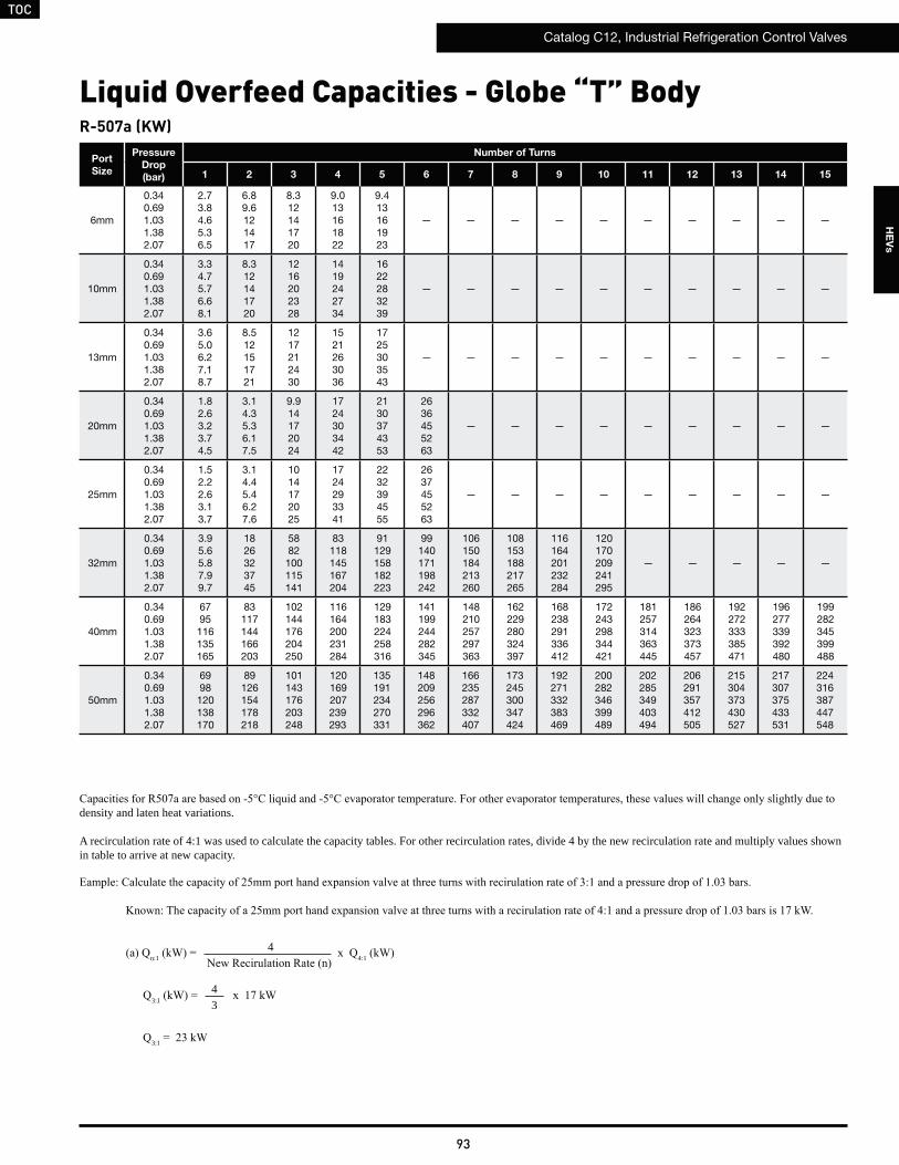
TOC
Catalog C12, Industrial Refrigeration Control Valves
93
HE
Vs
R-507a (KW)
Port
Size
Pressure
Drop
(bar)
Number of Turns
1 2 3 4 5 6 7 8 9 10 11 12 13 14 15
6mm
0.340.691.031.382.07
2.73.84.65.36.5
6.89.6121417
8.312141720
9.013161822
9.413161923
— — — — — — — — — —
10mm
0.340.691.031.382.07
3.34.75.76.68.1
8.312141720
1216202328
1419242734
1622283239
— — — — — — — — — —
13mm
0.340.691.031.382.07
3.65.06.27.18.7
8.512151721
1217212430
1521263036
1725303543
— — — — — — — — — —
20mm
0.340.691.031.382.07
1.82.63.23.74.5
3.14.35.36.17.5
9.914172024
1724303442
2130374353
2636455263
— — — — — — — — —
25mm
0.340.691.031.382.07
1.52.22.63.13.7
3.14.45.46.27.6
1014172025
1724293341
2232394555
2637455263
— — — — — — — — —
32mm
0.340.691.031.382.07
3.95.65.87.99.7
1826323745
5882100115141
83118145167204
91129158182223
99140171198242
106150184213260
108153188217265
116164201232284
120170209241295
— — — — —
40mm
0.340.691.031.382.07
6795116135165
83117144166203
102144176204250
116164200231284
129183224258316
141199244282345
148210257297363
162229280324397
168238291336412
172243298344421
181257314363445
186264323373457
192272333385471
196277339392480
199282345399488
50mm
0.340.691.031.382.07
6998120138170
89126154178218
101143176203248
120169207239293
135191234270331
148209256296362
166235287332407
173245300347424
192271332383469
200282346399489
202285349403494
206291357412505
215304373430527
217307375433531
224316387447548
density and laten heat variations.
A recirculation rate of 4:1 was used to calculate the capacity tables. For other recirculation rates, divide 4 by the new recirculation rate and multiply values shown in table to arrive at new capacity.
Liquid Overfeed Capacities - Globe “T” Body
n:1 4:1
3:1
3:1
4
43
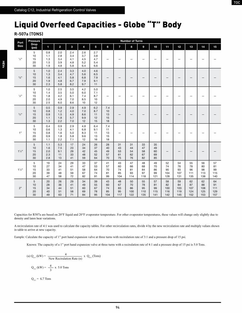
TOC
Catalog C12, Industrial Refrigeration Control Valves
94
HE
Vs
R-507a (TONS)
Port
Size
Pressure
Drop
(psi)
Number of Turns
1 2 3 4 5 6 7 8 9 10 11 12 13 14 15
1 ⁄4”
510152030
0.81.11.31.51.9
2.02.83.43.94.8
2.43.44.14.85.8
2.63.74.55.26.4
2.73.84.75.46.6
— — — — — — — — — —
3⁄8”
510152030
1.01.31.61.92.3
2.43.44.14.85.8
3.34.75.86.78.2
4.05.66.87.99.7
4.66.57.99.111
— — — — — — — — — —
1⁄2”
510152030
1.01.41.82.02.5
2.53.54.24.96.0
3.55.06.17.08.6
4.26.07.48.510
5.07.18.71012
— — — — — — — — — —
3⁄4”
510152030
0.50.80.91.11.3
0.91.21.51.82.2
2.94.04.95.77.0
4.97.08.69.912
6.28.7111215
7.410131518
— — — — — — — — —
1”
510152030
0.40.60.80.91.1
0.91.31.61.82.2
2.94.15.05.87.1
4.86.88.39.612
6.49.1111316
7.411131518
— — — — — — — — —
11⁄4”
510152030
1.11.62.02.32.8
5.37.59.11113
1723293341
2434424859
2637455264
2840495770
3143536175
3144546276
3347586782
3549606985
— — — — —
11⁄2”
510152030
1927333947
2434414858
2941515972
3347586782
3753647491
4157708199
43607485
104
47668193
114
48688497
118
49708699
121
527490
104128
547693
107131
557896
111135
568098
113138
578199115140
2”
510152030
2028344049
2636445163
2941515871
3449606984
3955677895
43607485
104
48678395
117
507086
100122
557895
110135
578199
115141
5882
100116142
5984
103119145
6287
107124152
6288
108125153
6491111129157
density and laten heat variations.
A recirculation rate of 4:1 was used to calculate the capacity tables. For other recirculation rates, divide 4 by the new recirculation rate and multiply values shown in table to arrive at new capacity.
Liquid Overfeed Capacities - Globe “T” Body
n:1 4:1 (Tons)
3:1
3:1 = 6.7 Tons
4
43
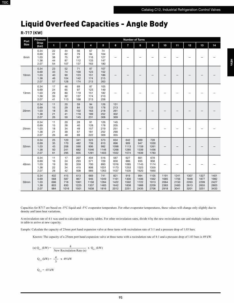
TOC
Catalog C12, Industrial Refrigeration Control Valves
95
HE
Vs
R-717 (KW)
Port
Size
Pressure
Drop
(bar)
Number of Turns
1 2 3 4 5 6 7 8 9 10 11 12 13 14
6mm
0.340.691.031.382.07
2231384454
44627587107
567997112137
6794116133163
74104127147180
— — — — — — — — —
10mm
0.340.691.031.382.07
2333404657
527490104128
71100123142174
87123151174213
107152186215263
— — — — — — — — —
13mm
0.340.691.031.382.07
1724293341
46658092113
6997119137168
87123151174213
105149182210258
— — — — — — — — —
20mm
0.340.691.031.382.07
1115182126
2029354150
5984102118145
94133163189231
126178218252308
151213261302369
— — — — — — — —
25mm
0.340.691.031.382.07
1115182126
2028343948
2840495769
91128157181222
126178219252309
145205251290355
— — — — — — — —
32mm
0.340.691.031.382.07
2535435061
120170208241295
341482590682835
52373990610461281
573810992
11461403
634896
109812681552
642909
111312851574
669947
115913391639
7281030126114561783
— — — — —
40mm
0.340.691.031.382.07
1116192228
1724303442
207293359415508
404571700808989
516729893
10311263
587830
101611731437
627886
108512531535
661935
114513231620
678958
117413551660
— — — — —
50mm
0.340.691.031.382.07
402568696803984
4155877188301016
613867106112251501
669946115813371638
7411049128414831816
8211161142216422012
9191300159218382251
9941406172219882435
11051562191322092706
11911685206423832918
12411756215024833041
13071848226326133201
13271877229926553251
14011982242728033433
density and laten heat variations.
A recirculation rate of 4:1 was used to calculate the capacity tables. For other recirculation rates, divide 4 by the new recirculation rate and multiply values shown in table to arrive at new capacity.
Liquid Overfeed Capacities - Angle Body
n:1 4:1
3:1
3:1
4
43
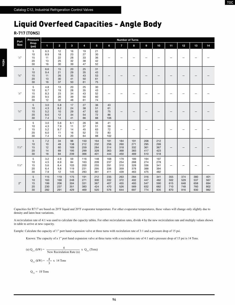
TOC
Catalog C12, Industrial Refrigeration Control Valves
96
HE
Vs
R-717 (TONS)
density and laten heat variations.
A recirculation rate of 4:1 was used to calculate the capacity tables. For other recirculation rates, divide 4 by the new recirculation rate and multiply values shown in table to arrive at new capacity.
Port
Size
Pressure
Drop
(psi)
Number of Turns
1 2 3 4 5 6 7 8 9 10 11 12 13 14
1 ⁄4”
510152030
6.38.9111316
1218222530
1623283239
1927333847
2130364252
— — — — — — — — —
3⁄8”
510152030
6.69.4111316
1521263037
2029354150
2535435061
3143536175
— — — — — — — — —
1⁄2”
510152030
4.86.78.39.512
1319232632
2028343948
2535435061
3043526074
— — — — — — — — —
3⁄4”
510152030
3.04.35.26.07.4
5.88.2101214
1724293441
2738475466
3651627288
43617586
106
— — — — — — — —
1”
510152030
3.04.35.26.07.4
5.67.99.71114
8.111141620
2637455264
3651637288
41597283
102
— — — — — — — —
11⁄4”
510152030
7.210121418
3449606984
98138169195239
150212259299366
164232284328401
181256314363444
184260318368450
191271332383469
208295361417510
212299367423518
— — — —
11⁄2”
510152030
3.24.55.66.47.9
4.96.98.49.812
5984103119145
116163200231283
148209255295361
168237291336411
179254310359439
189268328378463
194274336388475
197278341394482
— — — —
2”
510152030
115163199230282
119168206237291
175248304351429
191271331383469
212300367424520
235332407470576
263372455526644
284402493569697
316447547632774
341482590682835
355502615710870
374529648748916
380537658760930
401567694802982
Liquid Overfeed Capacities - Angle Body
n:1 4:1 (Tons)
3:1
3:1 = 19 Tons
4
43

TOC
Catalog C12, Industrial Refrigeration Control Valves
97
HE
Vs
R-22 (KW)
Port
Size
Pressure
Drop
(bar)
Number of Turns
1 2 3 4 5 6 7 8 9 10 11 12 13 14
6mm
0.340.691.031.382.07
5.17.28.91013
1014172025
1318222632
1522273138
1724303442
— — — — — — — — —
10mm
0.340.691.031.382.07
5.47.69.31113
1217212430
1623293340
2029354049
2535435061
— — — — — — — — —
13mm
0.340.691.031.382.07
3.95.56.77.79.5
1115182126
1622273239
2029354049
2434424960
— — — — — — — — —
20mm
0.340.691.031.382.07
2.43.44.24.96.0
4.76.78.19.412
1419242734
2231384453
2941505871
3549617086
— — — — — — — —
25mm
0.340.691.031.382.07
2.43.44.24.96.0
4.56.47.99.111
6.69.3111316
2130364251
2941515872
3448586782
— — — — — — — —
32mm
0.340.691.031.382.07
5.88.2101214
2839485668
79112137158193
121171210242297
133188230265325
147208254294360
149210258298365
155219269310380
169238292337413
— — — — —
40mm
0.340.691.031.382.07
2.63.74.55.26.4
3.95.66.87.99.7
48688396118
94132162187229
119169207239293
136192235272333
145205251290355
153217265306375
157222272314384
— — — — —
50mm
0.340.691.031.382.07
93132161186228
96136166192235
142201246284348
155219268310379
172243297343421
190269329380466
213301369426521
230326399461564
256362443512627
276390478552676
288407498575704
303428524605741
307435533615753
325459562649795
Liquid Overfeed Capacities - Angle Body
density and laten heat variations.
A recirculation rate of 4:1 was used to calculate the capacity tables. For other recirculation rates, divide 4 by the new recirculation rate and multiply values shown in table to arrive at new capacity.
n:1 4:1
3:1
3:1
4
43

TOC
Catalog C12, Industrial Refrigeration Control Valves
98
HE
Vs
R-22 (TONS)
Port
Size
Pressure
Drop
(psi)
Number of Turns
1 2 3 4 5 6 7 8 9 10 11 12 13 14
1 ⁄4”
510152030
1.52.12.52.93.6
2.94.15.05.87.1
3.75.26.47.49.1
4.46.37.78.911
4.96.98.59.812
— — — — — — — — —
3⁄8”
510152030
1.52.22.73.13.8
3.54.96.06.98.5
4.76.78.29.412
5.88.2101214
7.110121417
— — — — — — — — —
1⁄2”
510152030
1.11.61.92.22.7
3.14.35.36.17.5
4.66.47.9911
5.88.2101214
7.09.9121417
— — — — — — — — —
3⁄4”
510152030
0.71.01.21.41.7
1.31.92.32.73.3
3.95.66.87.89.6
6.38.9111315
8.412141720
1014172025
— — — — — — — —
1”
510152030
0.71.01.21.41.7
1.31.82.32.63.2
1.92.73.33.84.6
6.08.5101215
8.412151721
9.614171924
— — — — — — — —
11⁄4”
510152030
1.72.32.93.34.1
8.011141620
2332394555
3549606985
3854667693
42607384
103
43607485
105
44637789
109
48688497
118
— — — — —
11⁄2”
510152030
0.71.11.31.51.8
1.11.62.02.32.8
1419242834
2738465466
3448596884
3955677895
42597283
102
44627688
108
45647890
110
— — — — —
2”
510152030
2738465365
2839485567
41587081100
44637789109
49708598121
557794
109134
6186
106122150
6693
114132162
73104127147180
79112137158194
82117143165202
87123150174213
88125153176216
93132161186228
Liquid Overfeed Capacities - Angle Body
density and laten heat variations.
A recirculation rate of 4:1 was used to calculate the capacity tables. For other recirculation rates, divide 4 by the new recirculation rate and multiply values shown in table to arrive at new capacity.
n:1 4:1 (Tons)
3:1
3:1 = 4.4 Tons
4
43

TOC
Catalog C12, Industrial Refrigeration Control Valves
99
HE
Vs
R-134a (KW)
Port
Size
Pressure
Drop
(bar)
Number of Turns
1 2 3 4 5 6 7 8 9 10 11 12 13 14
6mm
0.340.691.031.382.07
5.07.08.61012
9.814172024
1318222531
1521263037
1723293341
— — — — — — — — —
10mm
0.340.691.031.382.07
5.27.49.11013
1217202429
1623283239
2028343948
2434424859
— — — — — — — — —
13mm
0.340.691.031.382.07
3.85.36.57.59.2
1015182125
1522273138
2028343948
2434414758
— — — — — — — — —
20mm
0.340.691.031.382.07
2.43.44.14.75.8
4.66.57.99.211
1319232733
2130374252
2840495769
3448596883
— — — — — — — —
25mm
0.340.691.031.382.07
2.43.44.14.75.8
4.46.27.68.811
6.49.0111316
2029354150
2840495770
3346576580
— — — — — — — —
32mm
0.340.691.031.382.07
5.68.09.81114
2738475466
77109133154188
118167204236289
129183224258316
143202247286350
145205251290355
151213261302369
164232284328402
— — — — —
40mm
0.340.691.031.382.07
2.53.64.45.16.2
3.85.46.77.79.4
47668193114
91129158182223
116164201232285
132187229264324
141200245282346
149211258298365
153216265305374
— — — — —
50mm
0.340.691.031.382.07
91128157181222
93132162187229
138195239276338
151213261301369
167236289334409
185262321370453
207293359414507
224317388448549
249352431498610
268380465537658
280396485560685
294416510589721
299423518598733
316447547632774
Liquid Overfeed Capacities - Angle Body
density and laten heat variations.
A recirculation rate of 4:1 was used to calculate the capacity tables. For other recirculation rates, divide 4 by the new recirculation rate and multiply values shown in table to arrive at new capacity.
n:1 4:1
3:1
3:1
4
43

TOC
Catalog C12, Industrial Refrigeration Control Valves
100
HE
Vs
R-134a (TONS)
Port
Size
Pressure
Drop
(psi)
Number of Turns
1 2 3 4 5 6 7 8 9 10 11 12 13 14
1 ⁄4”
510152030
1.42.02.52.93.5
2.84.04.95.66.9
3.65.16.27.28.8
4.36.17.58.611
4.86.78.29.512
— — — — — — — — —
3⁄8”
510152030
1.52.12.63.03.7
3.44.85.86.78.3
4.66.58.09.211
5.67.99.71114
6.99.8121417
— — — — — — — — —
1⁄2”
510152030
1.11.51.92.22.6
3.04.25.25.97.3
4.46.37.78.911
5.67.99.71114
6.89.6121417
— — — — — — — — —
3⁄4”
510152030
0.71.01.21.41.7
1.31.92.32.63.2
3.85.46.67.69.4
6.18.6111215
8.111141620
9.714171924
— — — — — — — —
1”
510152030
0.71.01.21.41.7
1.31.82.22.53.1
1.82.63.23.74.5
5.98.3101214
8.212141620
9.413161923
— — — — — — — —
11⁄4”
510152030
1.62.32.83.24.0
7.811131619
2231384454
3448586883
3752647491
41587182
100
42597283
102
43617586
106
47678194
115
— — — — —
11⁄2”
510152030
0.71.01.31.51.8
1.11.61.92.22.7
1319232733
2637455264
3347586782
3854667693
4057708199
43607485
105
44627688
107
— — — — —
2”
510152030
2637455264
2738465466
4056697997
43617586106
48688396117
537592
106130
5984
103119145
6491
111128157
71101124143175
77109133154189
80113139160196
84119146169207
86121149171210
91128157181222
Liquid Overfeed Capacities - Angle Body
density and laten heat variations.
A recirculation rate of 4:1 was used to calculate the capacity tables. For other recirculation rates, divide 4 by the new recirculation rate and multiply values shown in table to arrive at new capacity.
n:1 4:1 (Tons)
3:1
3:1 = 4.3 Tons
4
43

TOC
Catalog C12, Industrial Refrigeration Control Valves
101
HE
Vs
R-404a (KW)
Port
Size
Pressure
Drop
(bar)
Number of Turns
1 2 3 4 5 6 7 8 9 10 11 12 13 14
6mm
0.340.691.031.382.07
4.05.66.97.99.7
7.811131619
1014172024
1217212429
1319232632
— — — — — — — — —
10mm
0.340.691.031.382.07
4.25.97.28.310
9.313161923
1318222531
1622273138
1927333847
— — — — — — — — —
13mm
0.340.691.031.382.07
3.04.25.26.07.3
8.212141620
1217212530
1622273138
1927333846
— — — — — — — — —
20mm
0.340.691.031.382.07
1.92.73.33.84.6
3.65.16.37.38.9
1115182126
1724293441
2332394555
2738475466
— — — — — — — —
25mm
0.340.691.031.382.07
1.92.73.33.84.6
3.55.06.17.08.6
5.17.28.81012
1623283240
2332394555
2637455264
— — — — — — — —
32mm
0.340.691.031.382.07
4.56.37.89.011.0
2230374353
6186106122149
94132162187229
103145178205251
113160196227278
115163199230282
120169207240293
130184226261319
— — — — —
40mm
0.340.691.031.382.07
2.02.83.54.04.9
3.04.35.36.17.5
3752647491
72102125145177
92130160185226
105148182210257
112159194224275
118167205237290
121171210243297
— — — — —
50mm
0.340.691.031.382.07
72102125144176
74105129148182
110155190219269
120169207239293
133188230265325
147208255294360
164233285329403
178252308356436
198280342395484
213302369426522
222314385444544
234331405468573
238336411475582
251355434502614
Liquid Overfeed Capacities - Angle Body
density and laten heat variations.
A recirculation rate of 4:1 was used to calculate the capacity tables. For other recirculation rates, divide 4 by the new recirculation rate and multiply values shown in table to arrive at new capacity.
n:1 4:1
3:1
3:1
4
43
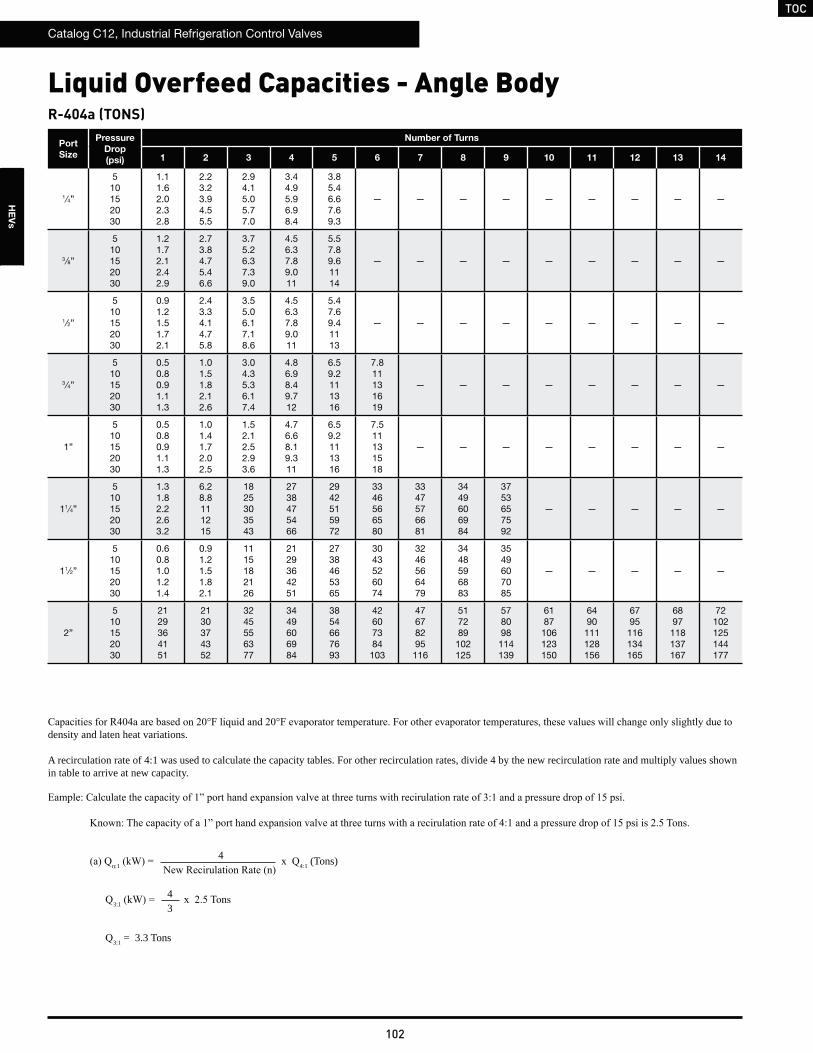
TOC
Catalog C12, Industrial Refrigeration Control Valves
102
HE
Vs
R-404a (TONS)
Port
Size
Pressure
Drop
(psi)
Number of Turns
1 2 3 4 5 6 7 8 9 10 11 12 13 14
1 ⁄4”
510152030
1.11.62.02.32.8
2.23.23.94.55.5
2.94.15.05.77.0
3.44.95.96.98.4
3.85.46.67.69.3
— — — — — — — — —
3⁄8”
510152030
1.21.72.12.42.9
2.73.84.75.46.6
3.75.26.37.39.0
4.56.37.89.011
5.57.89.61114
— — — — — — — — —
1⁄2”
510152030
0.91.21.51.72.1
2.43.34.14.75.8
3.55.06.17.18.6
4.56.37.89.011
5.47.69.41113
— — — — — — — — —
3⁄4”
510152030
0.50.80.91.11.3
1.01.51.82.12.6
3.04.35.36.17.4
4.86.98.49.712
6.59.2111316
7.811131619
— — — — — — — —
1”
510152030
0.50.80.91.11.3
1.01.41.72.02.5
1.52.12.52.93.6
4.76.68.19.311
6.59.2111316
7.511131518
— — — — — — — —
11⁄4”
510152030
1.31.82.22.63.2
6.28.8111215
1825303543
2738475466
2942515972
3346566580
3347576681
3449606984
3753657592
— — — — —
11⁄2”
510152030
0.60.81.01.21.4
0.91.21.51.82.1
1115182126
2129364251
2738465365
3043526074
3246566479
3448596883
3549607085
— — — — —
2”
510152030
2129364151
2130374352
3245556377
3449606984
3854667693
42607384
103
47678295
116
517289
102125
578098
114139
6187
106123150
6490
111128156
6795
116134165
6897
118137167
72102125144177
Liquid Overfeed Capacities - Angle Body
density and laten heat variations.
A recirculation rate of 4:1 was used to calculate the capacity tables. For other recirculation rates, divide 4 by the new recirculation rate and multiply values shown in table to arrive at new capacity.
n:1 4:1 (Tons)
3:1
3:1 = 3.3 Tons
4
43

TOC
Catalog C12, Industrial Refrigeration Control Valves
103
HE
Vs
R-410a (KW)
Port
Size
Pressure
Drop
(bar)
Number of Turns
1 2 3 4 5 6 7 8 9 10 11 12 13 14
6mm
0.340.691.031.382.07
5.37.59.21113
1015182126
1319232733
1623283239
1825313543
— — — — — — — — —
10mm
0.340.691.031.382.07
5.67.99.71114
1318222531
1724303442
2130364251
2637455263
— — — — — — — — —
13mm
0.340.691.031.382.07
4.05.77.08.09.8
1116192227
1723293340
2130364251
2536445162
— — — — — — — — —
20mm
0.340.691.031.382.07
2.53.64.45.16.2
4.96.98.59.812
1420252835
2332394556
3043536174
3651637389
— — — — — — — —
25mm
0.340.691.031.382.07
2.53.64.45.16.2
4.76.78.29.412
6.810121417
2231384454
3043536175
3549617086
— — — — — — — —
32mm
0.340.691.031.382.07
6.08.5101215
2941505871
82116142164201
126178218252309
138195239276338
153216265306374
155219268310379
161228279323395
176248304351430
— — — — —
40mm
0.340.691.031.382.07
2.73.84.75.46.6
4.15.87.18.210
507187100122
97138169195239
124176215249304
141200245283346
151214262302370
159225276319391
163231283327400
— — — — —
50mm
0.340.691.031.382.07
97137168194237
100141173200245
148209256295362
161228279322395
179253310358438
198280343396485
222313384443543
240339415479587
266377461533652
287406498574704
299423518599733
315446546630772
320453554640784
338478585676828
Liquid Overfeed Capacities - Angle Body
density and laten heat variations.
A recirculation rate of 4:1 was used to calculate the capacity tables. For other recirculation rates, divide 4 by the new recirculation rate and multiply values shown in table to arrive at new capacity.
n:1 4:1
3:1
3:1
4
43

TOC
Catalog C12, Industrial Refrigeration Control Valves
104
HE
Vs
R-410a (TONS)
Port
Size
Pressure
Drop
(psi)
Number of Turns
1 2 3 4 5 6 7 8 9 10 11 12 13 14
1 ⁄4”
510152030
1.52.22.73.13.8
3.04.35.26.07.4
3.95.56.77.79.5
4.66.58.09.211
5.17.28.81012
— — — — — — — — —
3⁄8”
510152030
1.62.32.83.23.9
3.65.16.37.28.9
4.97.08.59.912
6.08.5101215
7.411131518
— — — — — — — — —
1⁄2”
510152030
1.21.62.02.32.8
3.24.55.56.47.8
4.86.78.29.512
6.08.5101215
7.310131518
— — — — — — — — —
3⁄4”
510152030
0.71.01.31.51.8
1.42.02.42.83.4
4.15.87.18.210
6.59.2111316
8.712151721
1015182126
— — — — — — — —
1”
510152030
0.71.01.31.51.8
1.41.92.42.73.3
2.02.83.43.94.8
6.38.9111315
8.712151721
1014172025
— — — — — — — —
11⁄4”
510152030
1.72.53.03.54.2
8.312141720
2433414758
3651637289
4056697997
44627688
108
45637789
109
46668093
114
507187
101124
517389
103126
— — — —
11⁄2”
510152030
0.81.11.31.61.9
1.21.72.02.42.9
1420252935
2840485669
3651627188
41587081
100
43617587
106
46657992
112
47668194
115
48678395
117
— — — —
2”
510152030
2839485668
2941505870
42607485104
46668093114
517389103126
578199
114139
6490
110127156
6997
119138169
77108133153188
83117143165202
86122149172211
91128157181222
92130159184225
97137168194238
Liquid Overfeed Capacities - Angle Body
density and laten heat variations.
A recirculation rate of 4:1 was used to calculate the capacity tables. For other recirculation rates, divide 4 by the new recirculation rate and multiply values shown in table to arrive at new capacity.
n:1 4:1 (Tons)
3:1
3:1 = 4.5 Tons
4
43

TOC
Catalog C12, Industrial Refrigeration Control Valves
105
HE
Vs
R-507a (KW)
Port
Size
Pressure
Drop
(bar)
Number of Turns
1 2 3 4 5 6 7 8 9 10 11 12 13 14
6mm
0.340.691.031.382.07
3.95.56.77.89.5
7.610.8131519
9.814172024
11.717202329
12.918222632
— — — — — — — — —
10mm
0.340.691.031.382.07
4.15.87.18.110
9.213161822
1218222531
1522263137
1927333846
— — — — — — — — —
13mm
0.340.691.031.382.07
2.94.15.15.97.2
8.111141620
1217212429
1522263137
1826323745
— — — — — — — — —
20mm
0.340.691.031.382.07
1.82.63.23.74.5
3.65.06.27.18.7
1015182125
1723293341
2231384454
2637465365
— — — — — — — —
25mm
0.340.691.031.382.07
1.82.63.23.74.5
3.44.96.06.98.4
5.07.08.69.912
1622283239
2231384454
2536445162
— — — — — — — —
32mm
0.340.691.031.382.07
4.46.27.68.811
2130374252
6085104120147
92130159184225
101142174201246
111157193222272
113159195226276
117166203235288
128181221256313
— — — — —
40mm
0.340.691.031.382.07
2.02.83.43.94.8
3.04.25.26.07.3
3651637389
71100123142174
90128157181222
103146178206252
110156190220269
116164201232284
119168206238291
— — — — —
50mm
0.340.691.031.382.07
71100122141173
73103126146178
108152186215263
117166203235287
130184225260319
144204250288353
161228279323395
174247302349427
194274336388475
209296362418512
218308377436534
229324397459562
233329403466571
246348426492602
Liquid Overfeed Capacities - Angle Body
density and laten heat variations.
A recirculation rate of 4:1 was used to calculate the capacity tables. For other recirculation rates, divide 4 by the new recirculation rate and multiply values shown in table to arrive at new capacity.
n:1 4:1
3:1
3:1
4
43

TOC
Catalog C12, Industrial Refrigeration Control Valves
106
HE
Vs
R-507a (TONS)
Port
Size
Pressure
Drop
(psi)
Number of Turns
1 2 3 4 5 6 7 8 9 10 11 12 13 14
1 ⁄4”
510152030
1.11.61.92.22.7
2.23.13.84.45.4
2.84.04.95.66.9
3.44.85.86.78.2
3.75.36.47.49.1
— — — — — — — — —
3⁄8”
510152030
1.21.72.02.32.9
2.63.74.65.36.5
3.65.16.27.28.8
4.46.27.68.811
5.47.79.41113
— — — — — — — — —
1⁄2”
510152030
0.81.21.51.72.1
2.33.34.04.65.7
3.54.96.06.98.5
4.46.27.68.811
5.37.59.21113
— — — — — — — — —
3⁄4”
510152030
0.50.80.91.11.3
1.01.41.82.02.5
3.04.25.26.07.3
4.86.78.29.512
6.39.0111316
7.611131519
— — — — — — — —
1”
510152030
0.50.80.91.11.3
1.01.41.72.02.4
1.42.02.52.93.5
4.66.57.99.111
6.49.0111316
7.310131518
— — — — — — — —
11⁄4”
510152030
1.31.82.22.53.1
6.18.6111215
1724303442
2637465365
2941505871
3245556478
3246566579
3448586883
3752647390
— — — — —
11⁄2”
510152030
0.60.81.01.11.4
0.91.21.51.72.1
1015182126
2029354150
2637455264
3042515973
3245556377
3347586782
3448596884
— — — — —
2”
510152030
2029354150
2130364251
3144546276
3448586783
3753657592
41597283
102
46668093
114
507187
100123
567997
111137
6085
104120147
6389
109125153
6693
114132162
6795
116134164
71100122141173
Liquid Overfeed Capacities - Angle Body
density and laten heat variations.
A recirculation rate of 4:1 was used to calculate the capacity tables. For other recirculation rates, divide 4 by the new recirculation rate and multiply values shown in table to arrive at new capacity.
n:1 4:1 (Tons)
3:1
3:1 = 3.3 Tons
4
43
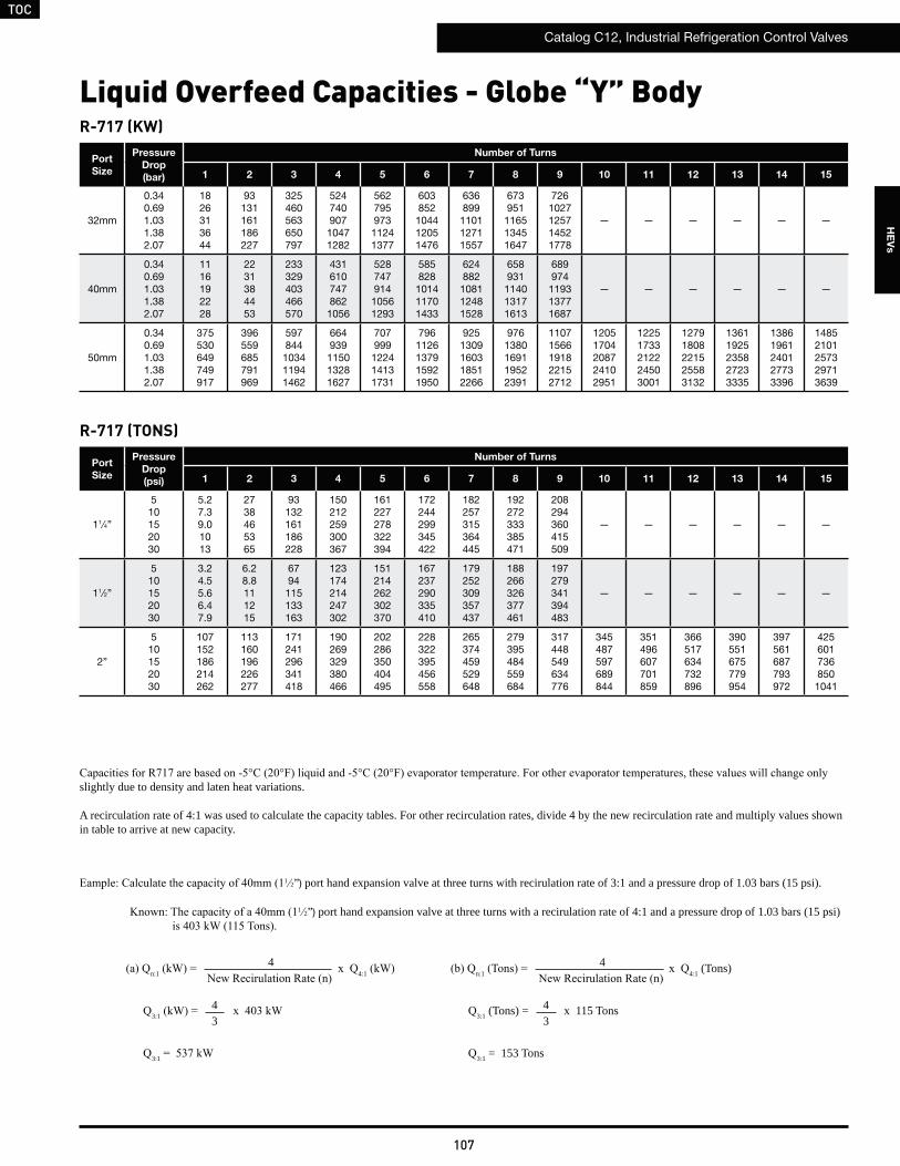
TOC
Catalog C12, Industrial Refrigeration Control Valves
107
HE
Vs
R-717 (KW)
Port
Size
Pressure
Drop
(bar)
Number of Turns
1 2 3 4 5 6 7 8 9 10 11 12 13 14 15
32mm
0.340.691.031.382.07
1826313644
93131161186227
325460563650797
52474090710471282
56279597311241377
603852
104412051476
636899
110112711557
673951
116513451647
7261027125714521778
— — — — — —
40mm
0.340.691.031.382.07
1116192228
2231384453
233329403466570
4316107478621056
52874791410561293
585828
101411701433
624882
108112481528
658931
114013171613
689974
119313771687
— — — — — —
50mm
0.340.691.031.382.07
375530649749917
396559685791969
597844103411941462
664939115013281627
707999122414131731
7961126137915921950
9251309160318512266
9761380169119522391
11071566191822152712
12051704208724102951
12251733212224503001
12791808221525583132
13611925235827233335
13861961240127733396
14852101257329713639
R-717 (TONS)
slightly due to density and laten heat variations.
A recirculation rate of 4:1 was used to calculate the capacity tables. For other recirculation rates, divide 4 by the new recirculation rate and multiply values shown in table to arrive at new capacity.
Port
Size
Pressure
Drop
(psi)
Number of Turns
1 2 3 4 5 6 7 8 9 10 11 12 13 14 15
11⁄4”
510152030
5.27.39.01013
2738465365
93132161186228
150212259300367
161227278322394
172244299345422
182257315364445
192272333385471
208294360415509
— — — — — —
11⁄2”
510152030
3.24.55.66.47.9
6.28.8111215
6794115133163
123174214247302
151214262302370
167237290335410
179252309357437
188266326377461
197279341394483
— — — — — —
2”
510152030
107152186214262
113160196226277
171241296341418
190269329380466
202286350404495
228322395456558
265374459529648
279395484559684
317448549634776
345487597689844
351496607701859
366517634732896
390551675779954
397561687793972
4256017368501041
Liquid Overfeed Capacities - Globe “Y” Body
1 2”) port hand expansion valve at three turns with recirulation rate of 3:1 and a pressure drop of 1.03 bars (15 psi).
1 2”) port hand expansion valve at three turns with a recirulation rate of 4:1 and a pressure drop of 1.03 bars (15 psi)
n:1 4:1 n:1 4:1 (Tons)
3:1 3:1 (Tons) = x 115 Tons
3:1 3:1 = 153 Tons
4
43
4
43
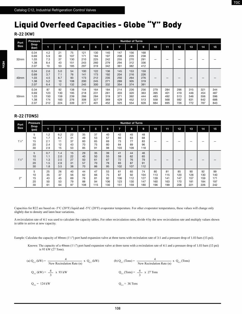
TOC
Catalog C12, Industrial Refrigeration Control Valves
108
HE
Vs
Liquid Overfeed Capacities - Globe “Y” BodyR-22 (KW)
Port
Size
Pressure
Drop
(bar)
Number of Turns
1 2 3 4 5 6 7 8 9 10 11 12 13 14 15
32mm
0.340.691.031.382.07
4.25.97.38.410
2130374353
75107130151185
121171210243297
130184225260319
140197242279342
147208255294361
156220270312382
168238291336412
— — — — — —
40mm
0.340.691.031.382.07
2.63.74.55.26.4
5.07.18.71012
547693108132
100141173200245
122173212245300
136192235271332
145204250289354
153216264305374
159226276319391
— — — — — —
50mm
0.340.691.031.382.07
87123150174212
92130159183224
138195239276339
154218266308377
164231284327401
184261319369452
214303371429525
226320392452554
256363444513628
279395483558684
284401492568695
296419513592726
315446546631772
321454556642787
344487596688843
R-22 (TONS)
Port
Size
Pressure
Drop
(psi)
Number of Turns
1 2 3 4 5 6 7 8 9 10 11 12 13 14 15
11⁄4”
510152030
1.21.72.12.42.9
6.28.7111215
2231374353
3549607085
3753657591
4057698098
42607384
103
45637789
109
48688396
118
— — — — — —
11⁄2”
510152030
0.71.11.31.51.8
1.42.02.52.93.5
1522273138
2940505770
3550617086
3955677895
41597283
102
44627687
107
46657991
112
— — — — — —
2”
510152030
2535435061
2637455364
4056697997
44627688108
47668194115
537592
106130
6187
106123151
6592
112130159
74104127147180
80113139160196
81115141163199
85120147170208
90128157181221
92130159184226
99140171197242
slightly due to density and laten heat variations.
A recirculation rate of 4:1 was used to calculate the capacity tables. For other recirculation rates, divide 4 by the new recirculation rate and multiply values shown in table to arrive at new capacity.
1 2”) port hand expansion valve at three turns with recirulation rate of 3:1 and a pressure drop of 1.03 bars (15 psi).
1 2”) port hand expansion valve at three turns with a recirulation rate of 4:1 and a pressure drop of 1.03 bars (15 psi)
n:1 4:1 n:1 4:1 (Tons)
3:1 3:1 (Tons) = x 27 Tons
3:1 3:1 = 36 Tons
4
43
4
43

TOC
Catalog C12, Industrial Refrigeration Control Valves
109
HE
Vs
R-134a (KW)
Port
Size
Pressure
Drop
(bar)
Number of Turns
1 2 3 4 5 6 7 8 9 10 11 12 13 14 15
32mm
0.340.691.031.382.07
4.15.87.18.210
2130364251
73104127147180
118167204236289
127179219253310
136192235272333
143203248286351
152214263303371
164231283327401
— — — — — —
40mm
0.340.691.031.382.07
2.53.64.45.16.2
4.96.98.59.812
527491105128
97137168194238
119168206238291
132187228264323
141199244281344
148210257297363
155219269310380
— — — — — —
50mm
0.340.691.031.382.07
84119146169207
89126154178218
134190233269329
150212259299367
159225276319390
179254311359440
209295361417511
220311381440539
250353432499611
272384470543665
276390478552676
288408499576706
307434531614752
312442541625765
335473580670820
R-134a (TONS)
Port
Size
Pressure
Drop
(psi)
Number of Turns
1 2 3 4 5 6 7 8 9 10 11 12 13 14 15
11⁄4”
510152030
1.21.72.02.32.9
6.08.5101215
2130364251
3448596883
3651637389
3955677895
41587182
101
43617587
106
47668194
115
— — — — — —
11⁄2”
510152030
0.71.01.31.51.8
1.42.02.42.83.4
1521263037
2839485668
3448596884
3853657693
4057708199
43607485
104
44637789
109
— — — — — —
2”
510152030
2434424859
2636445163
3955677794
43617486105
46657991112
517389
103126
6085
104120146
6389
109126154
72101124143175
78110135156191
79112137158194
83117143165202
88124152176215
90127155179219
96136166192235
Liquid Overfeed Capacities - Globe “Y” Body
slightly due to density and laten heat variations.
A recirculation rate of 4:1 was used to calculate the capacity tables. For other recirculation rates, divide 4 by the new recirculation rate and multiply values shown in table to arrive at new capacity.
1 2”) port hand expansion valve at three turns with recirulation rate of 3:1 and a pressure drop of 1.03 bars (15 psi).
1 2”) port hand expansion valve at three turns with a recirulation rate of 4:1 and a pressure drop of 1.03 bars (15 psi)
n:1 4:1 n:1 4:1 (Tons)
3:1 3:1 (Tons) = x 26 Tons
3:1 3:1 = 35 Tons
4
43
4
43
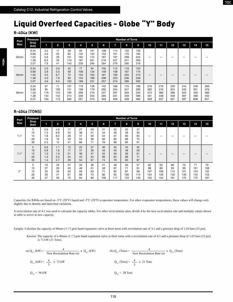
TOC
Catalog C12, Industrial Refrigeration Control Valves
110
HE
Vs
Liquid Overfeed Capacities - Globe “Y” BodyR-404a (KW)
Port
Size
Pressure
Drop
(bar)
Number of Turns
1 2 3 4 5 6 7 8 9 10 11 12 13 14 15
32mm
0.340.691.031.382.07
3.24.65.66.57.9
1723293341
5882101116143
94132162187229
101142174201246
108153187216264
114161197227279
120170208241295
130184225260318
— — — — — —
40mm
0.340.691.031.382.07
2.02.83.54.04.9
3.95.56.77.89.5
42597283102
77109134154189
94134164189231
105148181209257
112158193223274
118167204236289
123174213246302
— — — — — —
50mm
0.340.691.031.382.07
6795116134164
71100123142173
107151185214262
119168206238291
126179219253310
142202247285349
166234287331406
175247303349428
198280343396485
216305373431528
219310380438537
229324396458561
244345422487597
248351430496608
266376460532651
R-404a (TONS)
Port
Size
Pressure
Drop
(bar)
Number of Turns
1 2 3 4 5 6 7 8 9 10 11 12 13 14 15
11⁄4”
510152030
0.91.31.61.92.3
4.86.88.31012
1724293341
2738475466
2941505871
3144546276
3346576580
3549606985
3753657591
— — — — — —
11⁄2”
510152030
0.60.81.01.21.4
1.11.61.92.22.7
1217212429
2231384454
2738475467
3043526074
3245566479
3448596883
3550617187
— — — — — —
2”
510152030
1927333947
2029354150
3143536175
3448596884
3651637389
41587182
100
48678295
117
507187
100123
578199
114140
6288
107124152
6389
109126154
6693
114132161
7099
121140172
71101124143175
76108132153187
slightly due to density and laten heat variations.
A recirculation rate of 4:1 was used to calculate the capacity tables. For other recirculation rates, divide 4 by the new recirculation rate and multiply values shown in table to arrive at new capacity.
1 2”) port hand expansion valve at three turns with recirulation rate of 3:1 and a pressure drop of 1.03 bars (15 psi).
1 2”) port hand expansion valve at three turns with a recirulation rate of 4:1 and a pressure drop of 1.03 bars (15 psi)
n:1 4:1 n:1 4:1 (Tons)
3:1 3:1 (Tons) = x 21 Tons
3:1 3:1 = 28 Tons
4
43
4
43
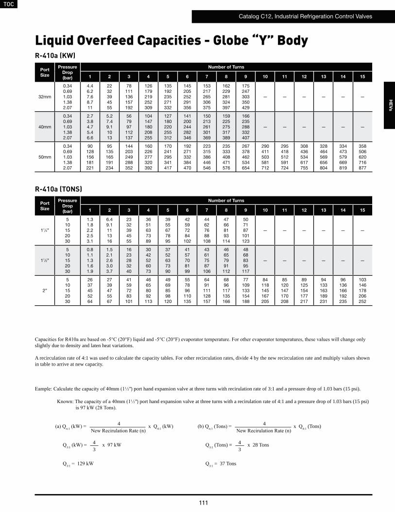
TOC
Catalog C12, Industrial Refrigeration Control Valves
111
HE
Vs
R-410a (KW)
Port
Size
Pressure
Drop
(bar)
Number of Turns
1 2 3 4 5 6 7 8 9 10 11 12 13 14 15
32mm
0.340.691.031.382.07
4.46.27.68.711
2232394555
78111136157192
126179219252309
135192235271332
145205252291356
153217265306375
162229281324397
175247303350429
— — — — — —
40mm
0.340.691.031.382.07
2.73.84.75.46.6
5.27.49.11013
567997112137
104147180208255
127180220255312
141200244282346
150213261301369
159225275317389
166235288332407
— — — — — —
50mm
0.340.691.031.382.07
90128156181221
95135165191234
144203249288352
160226277320392
170241295341417
192271332384470
223315386446546
235333408471576
267378462534654
290411503581712
295418512591724
308436534617755
328464569656804
334473579669819
358506620716877
R-410a (TONS)
Port
Size
Pressure
Drop
(bar)
Number of Turns
1 2 3 4 5 6 7 8 9 10 11 12 13 14 15
11⁄4”
510152030
1.31.82.22.53.1
6.49.1111316
2332394555
3651637389
3955677895
42597284
102
44627688
108
47668193
114
507187
101123
— — — — — —
11⁄2”
510152030
0.81.11.31.61.9
1.52.12.63.03.7
1623283240
3042526073
3752637390
4157708199
43617587
106
46657991
112
48688395
117
— — — — — —
2”
510152030
2637455264
2739475567
41597283101
46658092113
49698598120
557896
110135
6491
111128157
6896
117135166
77109133154188
84118145167205
85120147170208
89125154177217
94133163189231
96136166192235
103146178206252
Liquid Overfeed Capacities - Globe “Y” Body
slightly due to density and laten heat variations.
A recirculation rate of 4:1 was used to calculate the capacity tables. For other recirculation rates, divide 4 by the new recirculation rate and multiply values shown in table to arrive at new capacity.
1 2”) port hand expansion valve at three turns with recirulation rate of 3:1 and a pressure drop of 1.03 bars (15 psi).
1 2”) port hand expansion valve at three turns with a recirulation rate of 4:1 and a pressure drop of 1.03 bars (15 psi)
n:1 4:1 n:1 4:1 (Tons)
3:1 3:1 (Tons) = x 28 Tons
3:1 3:1 = 37 Tons
4
43
4
43

TOC
Catalog C12, Industrial Refrigeration Control Valves
112
HE
Vs
Liquid Overfeed Capacities - Globe “Y” BodyR-507a (KW)
Port
Size
Pressure
Drop
(bar)
Number of Turns
1 2 3 4 5 6 7 8 9 10 11 12 13 14 15
32mm
0.340.691.031.382.07
3.24.55.56.47.8
1623283340
578199114140
92130159184225
99139171197242
106150183212259
112158193223273
118167204236289
127180221255312
— — — — — —
40mm
0.340.691.031.382.07
2.02.83.43.94.8
3.85.46.67.69.4
41587182100
76107131151185
93131160185227
103145178205252
110155190219268
116163200231283
121171209242296
— — — — — —
50mm
0.340.691.031.382.07
6693114131161
6998120139170
105148181209257
117165202233286
124175215248304
140198242279342
162230281325398
171242297343420
194275337389476
211299366423518
215304372430527
224317389449550
239338414478585
243344421487596
261369452521639
R-507a (TONS)
Port
Size
Pressure
Drop
(bar)
Number of Turns
1 2 3 4 5 6 7 8 9 10 11 12 13 14 15
11⁄4”
510152030
0.91.31.61.82.2
4.76.68.19.411
1623283340
2637465365
2840495769
3043536174
3245566479
3448596883
3752637390
— — — — — —
11⁄2”
510152030
0.60.81.01.11.4
1.11.61.92.22.7
1217202329
2231384453
2738465365
3042515972
3145556377
3347586681
3549606985
— — — — — —
2”
510152030
1927333846
2028354049
3043526074
3447586782
3650627187
4057708098
47668193
114
49708599
121
567997
112137
6186
105122149
6287
107124151
6591
112129158
6997
119137168
7099
121140171
75106130150184
slightly due to density and laten heat variations.
A recirculation rate of 4:1 was used to calculate the capacity tables. For other recirculation rates, divide 4 by the new recirculation rate and multiply values shown in table to arrive at new capacity.
1 2”) port hand expansion valve at three turns with recirulation rate of 3:1 and a pressure drop of 1.03 bars (15 psi).
1 2”) port hand expansion valve at three turns with a recirulation rate of 4:1 and a pressure drop of 1.03 bars (15 psi)
n:1 4:1 n:1 4:1 (Tons)
3:1 3:1 (Tons) = x 20 Tons
3:1 3:1 = 27 Tons
4
43
4
43

TOC
Catalog C12, Industrial Refrigeration Control Valves
113
HE
Vs
Liquid Make Up Capacities - Globe “T” BodyR-717 (KW)
Port
Size
Evap.
Temp.
(˚C)
Number of Turns
1 2 3 4 5 6 7 8 9 10 11 12 13 14 15
6mm-5-20-30
146138133
372352338
453427411
494467449
515487468
— — — — — — — — — —
10mm-5-20-30
181171164
453427411
634598575
752710682
870822790
— — — — — — — — — —
13mm-5-20-30
195184177
466441423
668631607
808763733
954901866
— — — — — — — — — —
20mm-5-20-30
1019592
167158152
543513493
940888853
117311081065
141013311280
— — — — — — — — —
25mm-5-20-30
847976
171161155
550519499
912861828
122511571112
141313351283
— — — — — — — — —
32mm-5-20-30
216204196
1002947910
315429792863
456743134145
497847014518
540651064907
581354905277
592455955378
634959965763
658962235981
— — — — —
40mm-5-20-30
367934753340
453642844117
557352635059
633259805747
706666746414
770772796995
811076607362
885583648038
919786868348
941288908544
992893769011
1019996339258
1051999359548
10721101269732
10871102679868
50mm-5-20-30
378735773438
487346034423
554952405036
654461815940
739069796708
812476737375
907885748240
947889528604
1048499029517
10916103109909
110311041810013
112751064810234
117691111510683
118561119710762
122281154911100
R-717 (TONS)
Port
Size
Evap.
Temp.
(˚F)
Number of Turns
1 2 3 4 5 6 7 8 9 10 11 12 13 14 15
1 ⁄4”200
-20
414038
10510197
128123117
140134128
146140134
— — — — — — — — — —
3⁄8”200
-20
514947
128123117
179172164
212204195
246236226
— — — — — — — — — —
1⁄2”200
-20
555351
132126121
189181173
228219209
270258247
— — — — — — — — — —
3⁄4”200
-20
292726
474543
153147141
266255244
331318304
398382365
— — — — — — — — —
1”200
-20
242322
484644
155149143
258247236
346332318
399383366
— — — — — — — — —
11⁄4”200
-20
615856
283272260
891854818
129112371184
140713481291
152814641402
164315751507
167416051536
179417201646
186217851708
— — — — —
11⁄2”200
-20
1040997954
128212291176
157515101445
178917151642
199719141832
217820881998
229221972103
250223992296
259924912384
266025502440
280526892574
288227632644
297328502727
303029042780
307229452818
2”200
-20
10701026982
137713201263
156815031439
184917731697
208820021916
229622012106
256524592354
267925682457
296328402718
308529572830
311729882860
318630542923
332631883051
335032123074
345633133170

TOC
Catalog C12, Industrial Refrigeration Control Valves
114
HE
Vs
Liquid Make Up Capacities - Globe “T” BodyR-22 (KW)
Port
Size
Evap.
Temp.
(˚C)
Number of Turns
1 2 3 4 5 6 7 8 9 10 11 12 13 14 15
6mm-5-20-30
242120
615551
756661
817367
857670
— — — — — — — — — —
10mm-5-20-30
302725
756661
1049386
124110102
143128118
— — — — — — — — — —
13mm-5-20-30
322926
776963
1109891
133119110
157140129
— — — — — — — — — —
20mm-5-20-30
171514
282523
898074
155138128
193172159
232207191
— — — — — — — — —
25mm-5-20-30
141211
282523
918175
150134124
202180166
233208192
— — — — — — — — —
32mm-5-20-30
363229
165147136
519463428
752671620
820731675
890794733
957854789
976870804
1045933861
1085968894
— — — — —
40mm-5-20-30
606540499
747666615
918819756
1043930859
11641038959
126911321046
133511911100
145813011201
151413511248
155013831277
163514581347
167914981384
173215451427
176515751455
179015971475
50mm-5-20-30
624556514
802716661
914815753
1078961888
121710851003
133811931102
149513331232
156113921286
172615401423
179716031481
181616201497
185716561530
193817291597
195217411609
201417961659
R-22 (TONS)
Port
Size
Evap.
Temp.
(˚F)
Number of Turns
1 2 3 4 5 6 7 8 9 10 11 12 13 14 15
1 ⁄4”200
-20
7.06.55.9
181615
222018
242220
252321
— — — — — — — — — —
3⁄8”200
-20
8.78.07.3
222018
302826
363330
423835
— — — — — — — — — —
1⁄2”200
-20
9.48.67.9
222119
323027
393633
464239
— — — — — — — — — —
3⁄4”200
-20
4.84.54.1
8.07.46.8
262422
454238
565248
686257
— — — — — — — — —
1”200
-20
4.03.73.4
8.27.56.9
262422
444037
595450
686257
— — — — — — — — —
11⁄4”200
-20
109.58.7
484441
151139128
219202185
239220202
260239219
279257236
285262240
305281257
317291267
— — — — —
11⁄2”200
-20
177163149
218200184
268246226
304280257
339312286
370341312
390358329
425391359
442406373
452416382
477439402
490451413
505465426
515474435
522480441
2”200
-20
182167154
234215198
267245225
314289265
355327300
390359329
436401368
455419384
504463425
524482443
530488447
542498457
565520477
570524481
587540496

TOC
Catalog C12, Industrial Refrigeration Control Valves
115
HE
Vs
R-134a (KW)
R-134a (TONS)
Port
Size
Evap.
Temp.
(˚C)
Number of Turns
1 2 3 4 5 6 7 8 9 10 11 12 13 14 15
6mm-5-20-30
211715
524439
645448
705952
726154
— — — — — — — — — —
10mm-5-20-30
252219
645448
897567
1068979
12210392
— — — — — — — — — —
13mm-5-20-30
272321
665549
947971
1149685
134113101
— — — — — — — — — —
20mm-5-20-30
141211
232018
766557
13211299
165139124
198167149
— — — — — — — — —
25mm-5-20-30
12109
242018
776558
12810896
172146129
199168149
— — — — — — — — —
32mm-5-20-30
302623
141119106
443375333
642543482
700591526
760642571
817691614
833704626
893754671
927783696
— — — — —
40mm-5-20-30
517437389
638539479
784662589
890752669
994840746
1084916814
1141964857
12451052935
12931093971
13241118994
139611801048
143412121077
147912501111
150812741132
152912921148
50mm-5-20-30
533450400
685579515
780659586
920778691
1039878780
1142965858
12771079959
133311261001
147412461107
153512971153
155113111165
158513401191
165513981243
166714091252
172014531291
Port
Size
Evap.
Temp.
(˚F)
Number of Turns
1 2 3 4 5 6 7 8 9 10 11 12 13 14 15
1 ⁄4”200
-20
6.05.34.7
151412
191615
201816
211917
— — — — — — — — — —
3⁄8”200
-20
7.56.65.8
191615
262320
312724
363228
— — — — — — — — — —
1⁄2”200
-20
8.07.16.3
191715
282421
332926
393531
— — — — — — — — — —
3⁄4”200
-20
4.23.73.2
6.96.15.4
222017
393430
484338
585145
— — — — — — — — —
1”200
-20
3.43.02.7
7.06.25.5
232018
383329
504539
585145
— — — — — — — — —
11⁄4”200
-20
8.97.96.9
413732
130115101
188166146
205181160
223197173
239212186
244216190
261231204
271240211
— — — — —
11⁄2”200
-20
151134118
187165145
229203179
261231203
291257227
317281247
334295260
365323284
379335295
387343302
409362318
420371327
433383337
441391344
447396349
2”200
-20
156138121
201178156
228202178
269238210
304269237
334296261
374331291
390345304
432382336
449398350
454402354
464411362
484429377
488432380
503445392
Liquid Make Up Capacities - Globe “T” Body

TOC
Catalog C12, Industrial Refrigeration Control Valves
116
HE
Vs
R-404a (KW)
R-404a (TONS)
Port
Size
Evap.
Temp.
(˚C)
Number of Turns
1 2 3 4 5 6 7 8 9 10 11 12 13 14 15
6mm-5-20-30
13108.8
322622
393227
433530
453631
— — — — — — — — — —
10mm-5-20-30
161311
393227
554438
655345
756153
— — — — — — — — — —
13mm-5-20-30
171412
403328
584740
705749
836758
— — — — — — — — — —
20mm-5-20-30
8.77.16.1
141210
473833
816657
1028271
1229985
— — — — — — — — —
25mm-5-20-30
7.25.95.0
151210
483933
796455
1068674
1229985
— — — — — — — — —
32mm-5-20-30
191513
877061
273221190
395320276
431349300
468379326
503408351
513416358
550445383
570462398
— — — — —
40mm-5-20-30
318258222
393318274
482391336
548444382
612496427
667541465
702569490
766621535
796645555
815660568
859696599
883716616
911738635
928752647
941763656
50mm-5-20-30
328266229
422342294
480389335
566459395
640518446
703570490
786637548
820665572
907736633
945766659
955774666
976791681
1019826710
1026832716
1058858738
Port
Size
Evap.
Temp.
(˚F)
Number of Turns
1 2 3 4 5 6 7 8 9 10 11 12 13 14 15
1 ⁄4”200
-20
3.83.22.8
108.37.0
12108.6
13119.4
13119.7
— — — — — — — — — —
3⁄8”200
-20
4.74.03.4
12108.6
161412
191714
221916
— — — — — — — — — —
1⁄2”200
-20
5.04.33.7
12108.8
171513
211815
252118
— — — — — — — — — —
3⁄4”200
-20
2.62.21.9
4.33.73.2
141210
242118
302622
363127
— — — — — — — — —
1”200
-20
2.21.91.6
4.43.83.2
141210
242017
322723
363127
— — — — — — — — —
11⁄4”200
-20
5.64.84.1
262219
817060
11810186
12911194
140120102
150129110
153132112
164141120
170146125
— — — — —
11⁄2”200
-20
958270
11710186
144124105
164141120
182157134
199171146
209180153
229197168
238204174
243209178
256220188
263226193
272234199
277238203
281241206
2”200
-20
988472
12610892
143123105
169145124
191164140
210180154
234202172
245210179
271233198
282242207
285245209
291250213
304261223
306263224
316272231
Liquid Make Up Capacities - Globe “T” Body
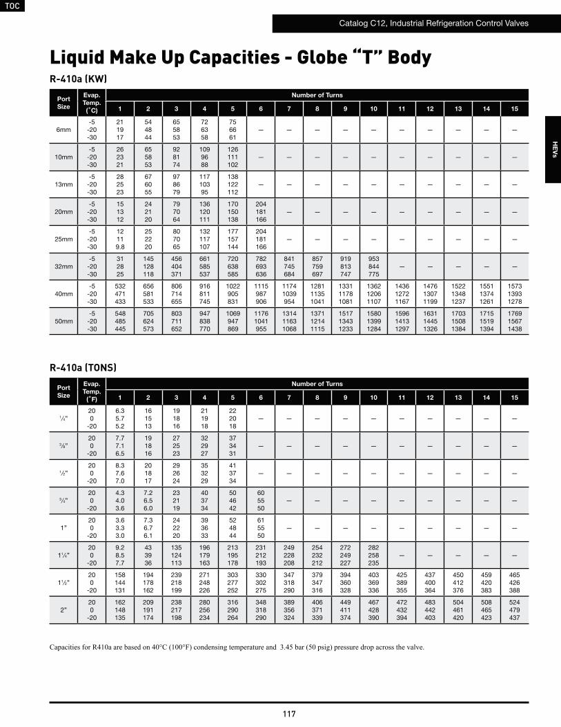
TOC
Catalog C12, Industrial Refrigeration Control Valves
117
HE
Vs
R-410a (KW)
R-410a (TONS)
Port
Size
Evap.
Temp.
(˚C)
Number of Turns
1 2 3 4 5 6 7 8 9 10 11 12 13 14 15
6mm-5-20-30
211917
544844
655853
726358
756661
— — — — — — — — — —
10mm-5-20-30
262321
655853
928174
1099688
126111102
— — — — — — — — — —
13mm-5-20-30
282523
676055
978679
11710395
138122112
— — — — — — — — — —
20mm-5-20-30
151312
242120
797064
136120111
170150138
204181166
— — — — — — — — —
25mm-5-20-30
12119.8
252220
807065
132117107
177157144
204181166
— — — — — — — — —
32mm-5-20-30
312825
145128118
456404371
661585537
720638585
782693636
841745684
857759697
919813747
953844775
— — — — —
40mm-5-20-30
532471433
656581533
806714655
916811745
1022905831
1115987906
11741039954
128111351041
133111781081
136212061107
143612721167
147613071199
152213481237
155113741261
157313931278
50mm-5-20-30
548485445
705624573
803711652
947838770
1069947869
11761041955
131411631068
137112141115
151713431233
158013991284
159614131297
163114451326
170315081384
171515191394
176915671438
Port
Size
Evap.
Temp.
(˚F)
Number of Turns
1 2 3 4 5 6 7 8 9 10 11 12 13 14 15
1 ⁄4”200
-20
6.35.75.2
161513
191816
211918
222018
— — — — — — — — — —
3⁄8”200
-20
7.77.16.5
191816
272523
322927
373431
— — — — — — — — — —
1⁄2”200
-20
8.37.67.0
201817
292624
353229
413734
— — — — — — — — — —
3⁄4”200
-20
4.34.03.6
7.26.56.0
232119
403734
504642
605550
— — — — — — — — —
1”200
-20
3.63.33.0
7.36.76.1
242220
393633
524844
615550
— — — — — — — — —
11⁄4”200
-20
9.28.57.7
433936
135124113
196179163
213195178
231212193
249228208
254232212
272249227
282258235
— — — — —
11⁄2”200
-20
158144131
194178162
239218199
271248226
303277252
330302275
347318290
379347316
394360328
403369336
425389355
437400364
450412376
459420383
465426388
2”200
-20
162148135
209191174
238217198
280256234
316290264
348318290
389356324
406371339
449411374
467428390
472432394
483442403
504461420
508465423
524479437
Liquid Make Up Capacities - Globe “T” Body
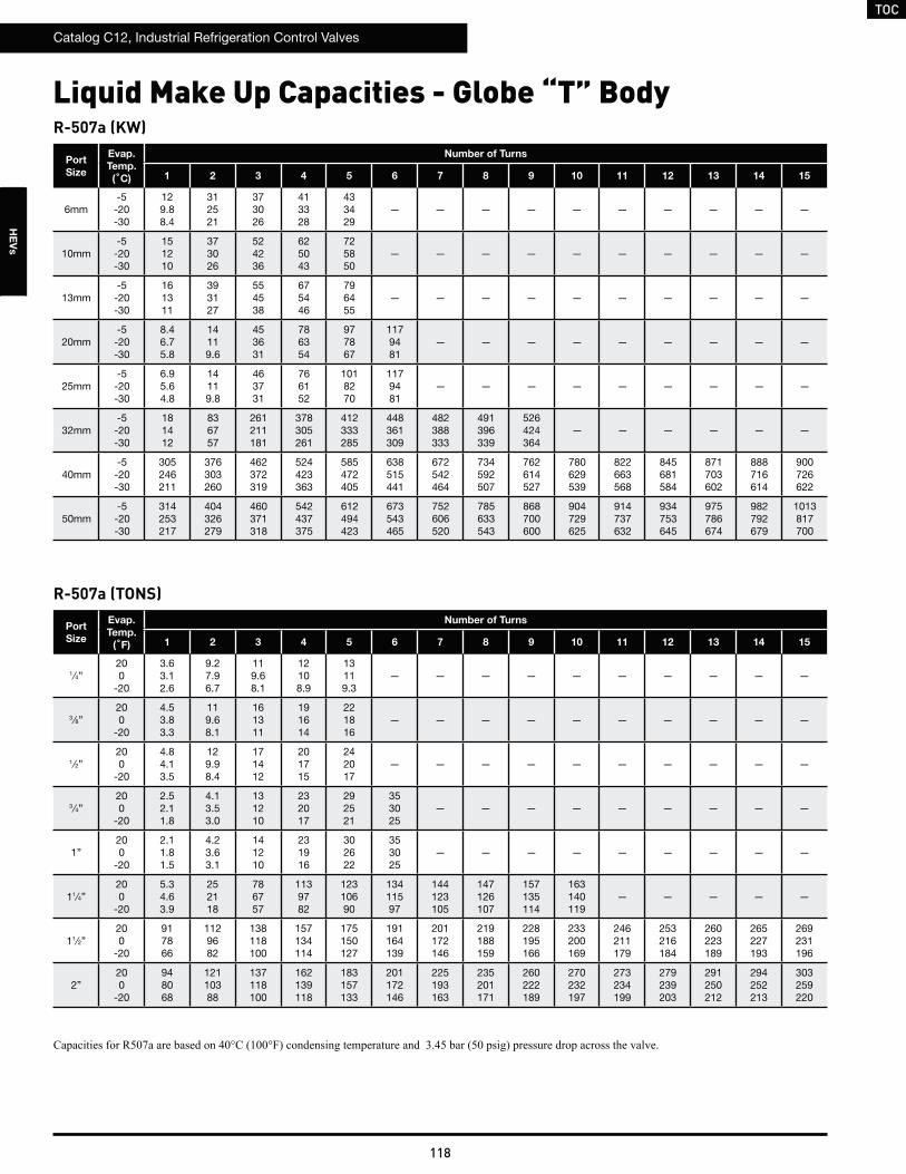
TOC
Catalog C12, Industrial Refrigeration Control Valves
118
HE
Vs
R-507a (KW)
R-507a (TONS)
Port
Size
Evap.
Temp.
(˚C)
Number of Turns
1 2 3 4 5 6 7 8 9 10 11 12 13 14 15
6mm-5-20-30
129.88.4
312521
373026
413328
433429
— — — — — — — — — —
10mm-5-20-30
151210
373026
524236
625043
725850
— — — — — — — — — —
13mm-5-20-30
161311
393127
554538
675446
796455
— — — — — — — — — —
20mm-5-20-30
8.46.75.8
14119.6
453631
786354
977867
1179481
— — — — — — — — —
25mm-5-20-30
6.95.64.8
14119.8
463731
766152
1018270
1179481
— — — — — — — — —
32mm-5-20-30
181412
836757
261211181
378305261
412333285
448361309
482388333
491396339
526424364
— — — — — —
40mm-5-20-30
305246211
376303260
462372319
524423363
585472405
638515441
672542464
734592507
762614527
780629539
822663568
845681584
871703602
888716614
900726622
50mm-5-20-30
314253217
404326279
460371318
542437375
612494423
673543465
752606520
785633543
868700600
904729625
914737632
934753645
975786674
982792679
1013817700
Port
Size
Evap.
Temp.
(˚F)
Number of Turns
1 2 3 4 5 6 7 8 9 10 11 12 13 14 15
1 ⁄4”200
-20
3.63.12.6
9.27.96.7
119.68.1
12108.9
13119.3
— — — — — — — — — —
3⁄8”200
-20
4.53.83.3
119.68.1
161311
191614
221816
— — — — — — — — — —
1⁄2”200
-20
4.84.13.5
129.98.4
171412
201715
242017
— — — — — — — — — —
3⁄4”200
-20
2.52.11.8
4.13.53.0
131210
232017
292521
353025
— — — — — — — — —
1”200
-20
2.11.81.5
4.23.63.1
141210
231916
302622
353025
— — — — — — — — —
11⁄4”200
-20
5.34.63.9
252118
786757
1139782
12310690
13411597
144123105
147126107
157135114
163140119
— — — — —
11⁄2”200
-20
917866
1129682
138118100
157134114
175150127
191164139
201172146
219188159
228195166
233200169
246211179
253216184
260223189
265227193
269231196
2”200
-20
948068
12110388
137118100
162139118
183157133
201172146
225193163
235201171
260222189
270232197
273234199
279239203
291250212
294252213
303259220
Liquid Make Up Capacities - Globe “T” Body
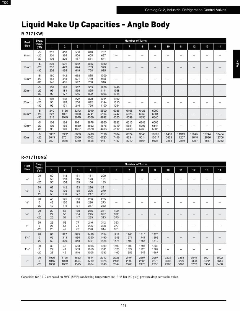
TOC
Catalog C12, Industrial Refrigeration Control Valves
119
HE
Vs
Liquid Make Up Capacities - Angle BodyR-717 (KW)
Port
Size
Evap.
Temp.
(˚C)
Number of Turns
1 2 3 4 5 6 7 8 9 10 11 12 13 14
6mm-5-20-30
212201193
418395379
536506487
640605581
707667641
— — — — — — — — —
10mm-5-20-30
223210202
501473455
682644619
835789758
1030973935
— — — — — — — — —
13mm-5-20-30
160151145
442418401
658621597
835789758
1009953916
— — — — — — — — —
20mm-5-20-30
1019592
195184177
567536515
905855822
120811411096
144813681314
— — — — — — — —
25mm-5-20-30
1019592
188178171
272256246
870822790
121111441100
139213151264
— — — — — — — —
32mm-5-20-30
240227218
115610911049
327230902970
501947414556
550051944992
608557475523
616858265599
642660695833
699066016345
— — — — —
40mm-5-20-30
10810298
164155149
199118801807
387836623520
495046754493
563253195112
601556815460
634959965763
650661445905
— — — — —
50mm-5-20-30
385736433501
398237613615
588355565340
641960625826
711867236461
788474467157
882483348010
954590148664
10606100179627
114381080310383
119191125710819
125451184811387
127441203611567
134541270612212
R-717 (TONS)
Port
Size
Evap.
Temp.
(˚F)
Number of Turns
1 2 3 4 5 6 7 8 9 10 11 12 13 14
1 ⁄4”200
-20
605855
118113108
151145139
181173166
200191183
— — — — — — — — —
3⁄8”200
-20
636058
142136130
193185177
236226217
291279267
— — — — — — — — —
1⁄2”200
-20
454342
125120115
186178171
236226217
285273262
— — — — — — — — —
3⁄4”200
-20
292726
555351
160154147
256245235
341327313
409392375
— — — — — — — —
1”200
-20
292726
535149
777470
246236226
342328314
393377361
— — — — — — — —
11⁄4”200
-20
686562
327313300
925886848
141813601301
155414901426
171916481578
174316711599
181617411666
197518931812
— — — — —
11⁄2”200
-20
302928
464442
563539516
109610501005
139913411283
159215261460
170016291559
179417201646
183817621687
— — — — —
2”200
-20
109010451000
112510791032
166215941525
181417391664
201219281846
222821362044
249423902288
269725862475
299728732750
323230982966
336832293090
354533983252
360134523304
380236443488
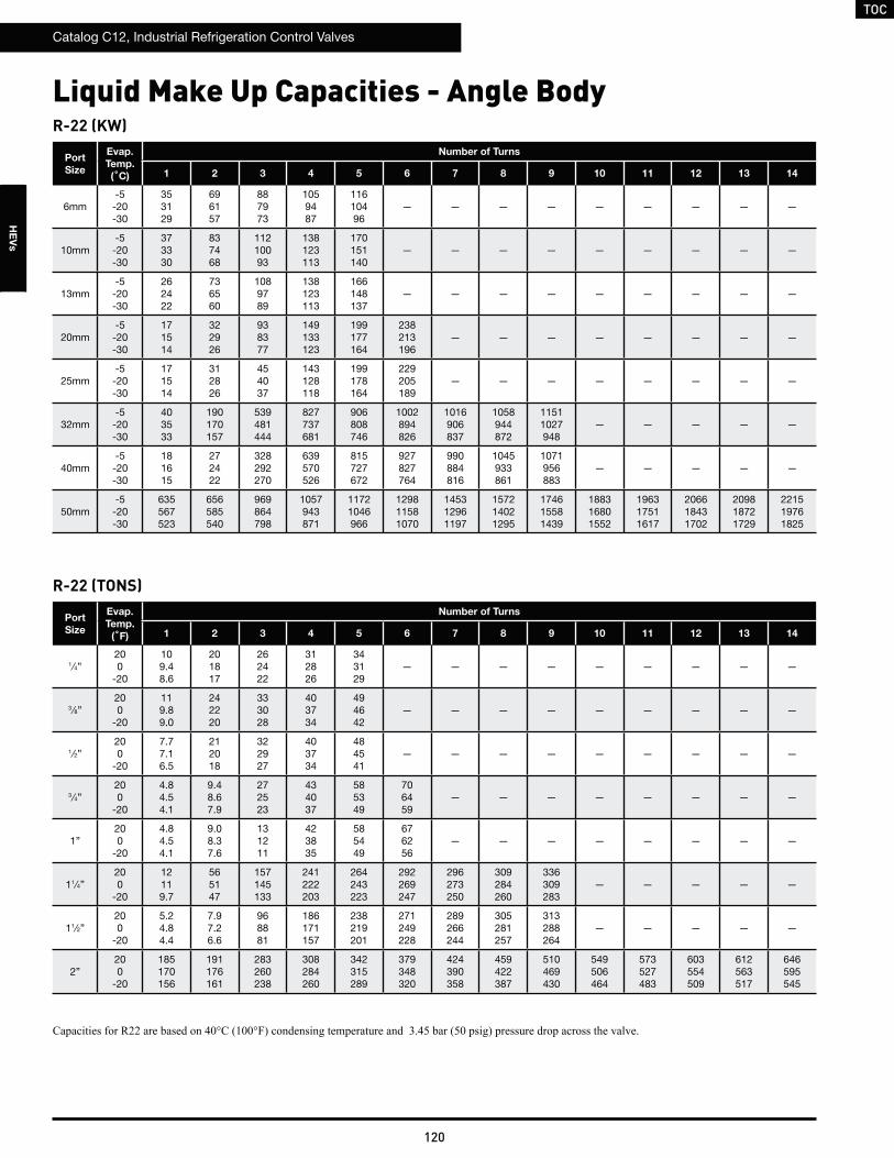
TOC
Catalog C12, Industrial Refrigeration Control Valves
120
HE
Vs
Liquid Make Up Capacities - Angle BodyR-22 (KW)
R-22 (TONS)
Port
Size
Evap.
Temp.
(˚C)
Number of Turns
1 2 3 4 5 6 7 8 9 10 11 12 13 14
6mm-5-20-30
353129
696157
887973
1059487
11610496
— — — — — — — — —
10mm-5-20-30
373330
837468
11210093
138123113
170151140
— — — — — — — — —
13mm-5-20-30
262422
736560
1089789
138123113
166148137
— — — — — — — — —
20mm-5-20-30
171514
322926
938377
149133123
199177164
238213196
— — — — — — — —
25mm-5-20-30
171514
312826
454037
143128118
199178164
229205189
— — — — — — — —
32mm-5-20-30
403533
190170157
539481444
827737681
906808746
1002894826
1016906837
1058944872
11511027948
— — — — —
40mm-5-20-30
181615
272422
328292270
639570526
815727672
927827764
990884816
1045933861
1071956883
— — — — —
50mm-5-20-30
635567523
656585540
969864798
1057943871
11721046966
129811581070
145312961197
157214021295
174615581439
188316801552
196317511617
206618431702
209818721729
221519761825
Port
Size
Evap.
Temp.
(˚F)
Number of Turns
1 2 3 4 5 6 7 8 9 10 11 12 13 14
1 ⁄4”200
-20
109.48.6
201817
262422
312826
343129
— — — — — — — — —
3⁄8”200
-20
119.89.0
242220
333028
403734
494642
— — — — — — — — —
1⁄2”200
-20
7.77.16.5
212018
322927
403734
484541
— — — — — — — — —
3⁄4”200
-20
4.84.54.1
9.48.67.9
272523
434037
585349
706459
— — — — — — — —
1”200
-20
4.84.54.1
9.08.37.6
131211
423835
585449
676256
— — — — — — — —
11⁄4”200
-20
12119.7
565147
157145133
241222203
264243223
292269247
296273250
309284260
336309283
— — — — —
11⁄2”200
-20
5.24.84.4
7.97.26.6
968881
186171157
238219201
271249228
289266244
305281257
313288264
— — — — —
2”200
-20
185170156
191176161
283260238
308284260
342315289
379348320
424390358
459422387
510469430
549506464
573527483
603554509
612563517
646595545
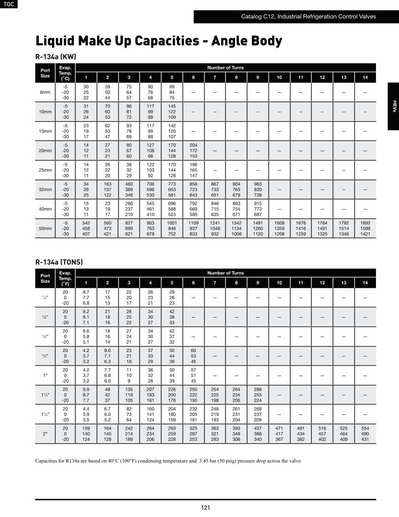
TOC
Catalog C12, Industrial Refrigeration Control Valves
121
HE
Vs
Liquid Make Up Capacities - Angle BodyR-134a (KW)
R-134a (TONS)
Port
Size
Evap.
Temp.
(˚C)
Number of Turns
1 2 3 4 5 6 7 8 9 10 11 12 13 14
6mm-5-20-30
302522
595044
756457
907668
998475
— — — — — — — — —
10mm-5-20-30
312624
706053
968172
1179988
145122109
— — — — — — — — —
13mm-5-20-30
231917
625347
937869
1179988
142120107
— — — — — — — — —
20mm-5-20-30
141211
272321
806760
12710896
170144128
204172153
— — — — — — — —
25mm-5-20-30
141211
262220
383229
12210392
170144128
196165147
— — — — — — — —
32mm-5-20-30
342925
163137122
460389346
706596530
773653581
856723643
867733651
904763679
983830738
— — — — —
40mm-5-20-30
151311
231917
280237210
545461410
696588523
792669595
846715635
893754671
915773687
— — — — —
50mm-5-20-30
542458407
560473421
827699621
903763678
1001846752
1109937833
12411048932
134211341008
149112601120
160813591208
167614161259
176414911325
179215141346
189215981421
Port
Size
Evap.
Temp.
(˚F)
Number of Turns
1 2 3 4 5 6 7 8 9 10 11 12 13 14
1 ⁄4”200
-20
8.77.76.8
171513
222017
262321
292623
— — — — — — — — —
3⁄8”200
-20
9.28.17.1
211816
282522
343027
423833
— — — — — — — — —
1⁄2”200
-20
6.65.85.1
181614
272421
343027
423732
— — — — — — — — —
3⁄4”200
-20
4.23.73.2
8.07.16.3
232118
373329
504439
605346
— — — — — — — —
1”200
-20
4.23.73.2
7.76.86.0
11109
363228
504439
575145
— — — — — — — —
11⁄4”200
-20
9.98.77.7
484237
135119105
207183161
226200176
250222195
254225198
264234206
288255224
— — — — —
11⁄2”200
-20
4.43.93.5
6.76.05.2
827364
160141124
204180159
232205181
248219193
261231204
268237209
— — — — —
2”200
-20
159140124
164145128
242214189
264234206
293259228
325287253
363321283
393348306
437386340
471417367
491434382
516457402
525464409
554490431

TOC
Catalog C12, Industrial Refrigeration Control Valves
122
HE
Vs
Liquid Make Up Capacities - Angle BodyR-404a (KW)
R-404a (TONS)
Port
Size
Evap.
Temp.
(˚C)
Number of Turns
1 2 3 4 5 6 7 8 9 10 11 12 13 14
6mm-5-20-30
181513
362925
463832
554539
615043
— — — — — — — — —
10mm-5-20-30
191613
433530
594841
725950
897262
— — — — — — — — —
13mm-5-20-30
14119.7
383127
574640
725950
877161
— — — — — — — — —
20mm-5-20-30
8.77.16.1
171412
494034
786355
1058573
12510287
— — — — — — — —
25mm-5-20-30
8.77.16.1
161311
241916
756153
1058573
1219884
— — — — — — — —
32mm-5-20-30
211714
1008170
283230198
434352303
476386332
527427367
534433372
556451388
605490422
— — — — —
40mm-5-20-30
9.37.66.5
141110
172140120
336272234
428347299
487395340
521422363
550445383
563456393
— — — — —
50mm-5-20-30
334271233
345279240
509413355
556450387
616499430
682553476
764619533
826670576
918744640
990802691
1032836720
1086880757
1103894769
1164944812
Port
Size
Evap.
Temp.
(˚F)
Number of Turns
1 2 3 4 5 6 7 8 9 10 11 12 13 14
1 ⁄4”200
-20
5.54.74.0
119.37.9
141210
171412
181613
— — — — — — — — —
3⁄8”200
-20
5.84.94.2
13119.5
181513
221916
272319
— — — — — — — — —
1⁄2”200
-20
4.13.63.0
119.88.4
171512
221916
262219
— — — — — — — — —
3⁄4”200
-20
2.62.21.9
5.04.33.7
151311
232017
312723
373227
— — — — — — — —
1”200
-20
2.62.21.9
4.94.23.6
7.06.05.1
221916
312723
363126
— — — — — — — —
11⁄4”200
-20
6.25.34.5
302622
857362
13011195
142122104
157135115
159137117
166143122
181155132
— — — — —
11⁄2”200
-20
2.82.42.0
4.23.63.1
514438
1008673
12811094
145125107
155134114
164141120
168144123
— — — — —
2”200
-20
1008673
1038875
152131111
166143121
184158135
204175149
228196167
246212181
274236201
295254216
308265226
324279237
329283241
347299255
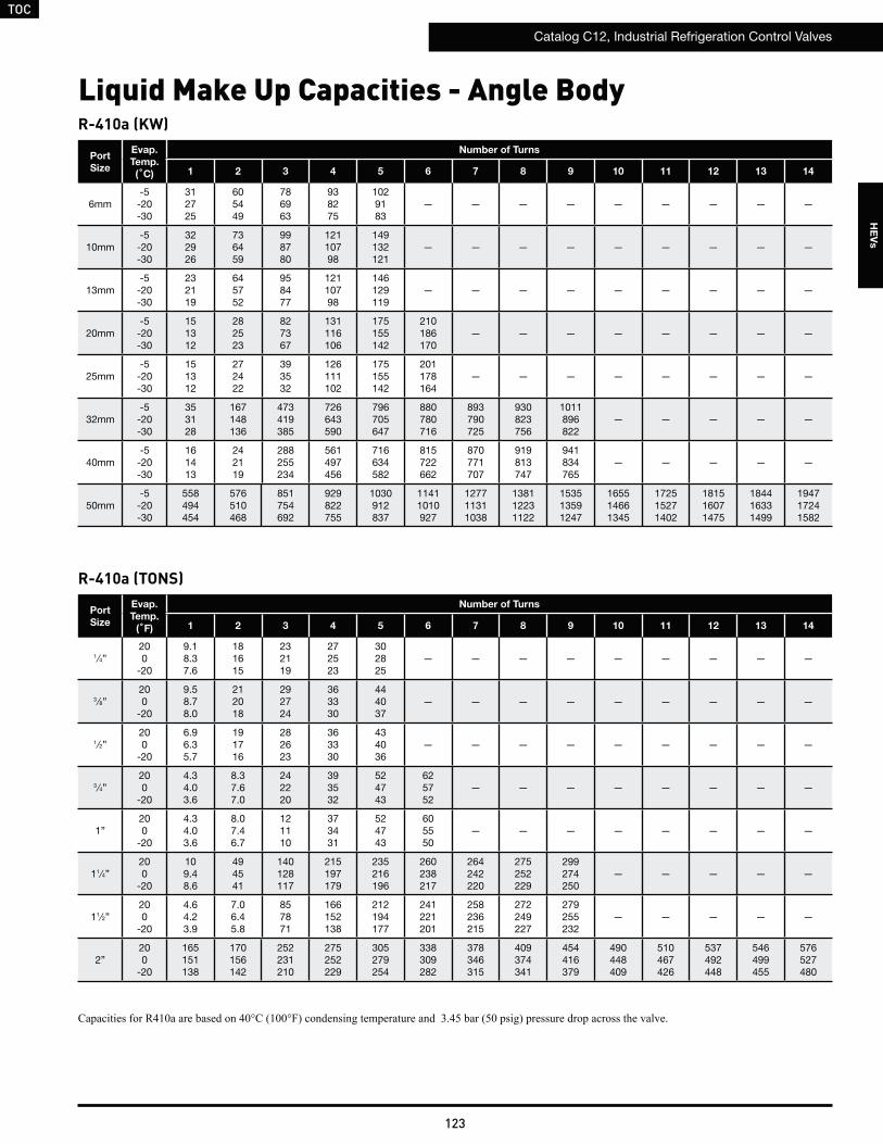
TOC
Catalog C12, Industrial Refrigeration Control Valves
123
HE
Vs
Liquid Make Up Capacities - Angle BodyR-410a (KW)
R-410a (TONS)
Port
Size
Evap.
Temp.
(˚C)
Number of Turns
1 2 3 4 5 6 7 8 9 10 11 12 13 14
6mm-5-20-30
312725
605449
786963
938275
1029183
— — — — — — — — —
10mm-5-20-30
322926
736459
998780
12110798
149132121
— — — — — — — — —
13mm-5-20-30
232119
645752
958477
12110798
146129119
— — — — — — — — —
20mm-5-20-30
151312
282523
827367
131116106
175155142
210186170
— — — — — — — —
25mm-5-20-30
151312
272422
393532
126111102
175155142
201178164
— — — — — — — —
32mm-5-20-30
353128
167148136
473419385
726643590
796705647
880780716
893790725
930823756
1011896822
— — — — —
40mm-5-20-30
161413
242119
288255234
561497456
716634582
815722662
870771707
919813747
941834765
— — — — —
50mm-5-20-30
558494454
576510468
851754692
929822755
1030912837
11411010927
127711311038
138112231122
153513591247
165514661345
172515271402
181516071475
184416331499
194717241582
Port
Size
Evap.
Temp.
(˚F)
Number of Turns
1 2 3 4 5 6 7 8 9 10 11 12 13 14
1 ⁄4”200
-20
9.18.37.6
181615
232119
272523
302825
— — — — — — — — —
3⁄8”200
-20
9.58.78.0
212018
292724
363330
444037
— — — — — — — — —
1⁄2”200
-20
6.96.35.7
191716
282623
363330
434036
— — — — — — — — —
3⁄4”200
-20
4.34.03.6
8.37.67.0
242220
393532
524743
625752
— — — — — — — —
1”200
-20
4.34.03.6
8.07.46.7
121110
373431
524743
605550
— — — — — — — —
11⁄4”200
-20
109.48.6
494541
140128117
215197179
235216196
260238217
264242220
275252229
299274250
— — — — —
11⁄2”200
-20
4.64.23.9
7.06.45.8
857871
166152138
212194177
241221201
258236215
272249227
279255232
— — — — —
2”200
-20
165151138
170156142
252231210
275252229
305279254
338309282
378346315
409374341
454416379
490448409
510467426
537492448
546499455
576527480

TOC
Catalog C12, Industrial Refrigeration Control Valves
124
HE
Vs
Liquid Make Up Capacities - Angle BodyR-507a (KW)
R-507a (TONS)
Port
Size
Evap.
Temp.
(˚C)
Number of Turns
1 2 3 4 5 6 7 8 9 10 11 12 13 14
6mm-5-20-30
181412
352824
443631
534337
594740
— — — — — — — — —
10mm-5-20-30
181513
423329
574639
695648
856959
— — — — — — — — —
13mm-5-20-30
13119.2
373025
544438
695648
846758
— — — — — — — — —
20mm-5-20-30
8.46.75.8
161311
473832
756052
1008169
1209783
— — — — — — — —
25mm-5-20-30
8.46.75.8
161311
221816
725850
1008169
1159380
— — — — — — — —
32mm-5-20-30
201614
967766
271219187
416335287
456367315
504406348
511412353
532429368
579467400
— — — — —
40mm-5
-20-30
8.97.26.2
14119.4
165133114
321259222
410331283
467376322
498402344
526424364
539435372
— — — — —
50mm-5-20-30
319258221
330266228
487393337
532429367
590476408
653527451
731589505
791638546
879709607
947764655
987796682
1039838718
1056851730
1114899770
Port
Size
Evap.
Temp.
(˚F)
Number of Turns
1 2 3 4 5 6 7 8 9 10 11 12 13 14
1 ⁄4”200
-20
5.34.53.8
108.97.5
131110
161412
171513
— — — — — — — — —
3⁄8”200
-20
5.54.74.0
12119.0
171412
211815
262219
— — — — — — — — —
1⁄2”200
-20
4.03.42.9
119.48.0
161412
211815
252118
— — — — — — — — —
3⁄4”200
-20
2.52.11.8
4.84.13.5
141210
221916
302622
363126
— — — — — — — —
1”200
-20
2.52.11.8
4.74.03.4
6.75.84.9
221816
302622
343025
— — — — — — — —
11⁄4”200
-20
5.95.14.3
292521
816959
12410790
13611799
151129110
153131111
159136116
173148126
— — — — —
11⁄2”200
-20
2.72.31.9
4.13.52.9
494236
968270
12310589
139120101
149128108
157135114
161138117
— — — — —
2”200
-20
968269
998472
146125106
159136116
176151128
195167142
219187159
236203172
263225191
283243206
295253215
311266226
316270229
333285242
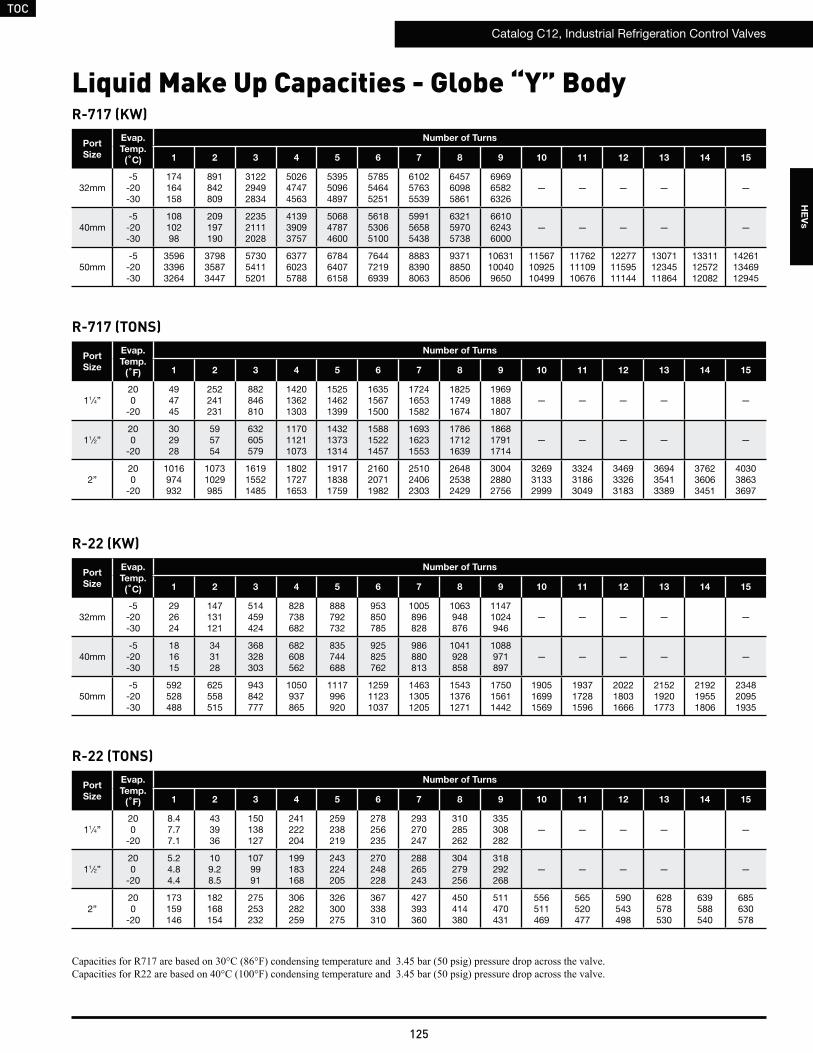
TOC
Catalog C12, Industrial Refrigeration Control Valves
125
HE
Vs
Liquid Make Up Capacities - Globe “Y” BodyR-717 (KW)
Port
Size
Evap.
Temp.
(˚C)
Number of Turns
1 2 3 4 5 6 7 8 9 10 11 12 13 14 15
32mm-5-20-30
174164158
891842809
312229492834
502647474563
539550964897
578554645251
610257635539
645760985861
696965826326
— — — — —
40mm-5-20-30
10810298
209197190
223521112028
413939093757
506847874600
561853065100
599156585438
632159705738
661062436000
— — — — —
50mm-5-20-30
359633963264
379835873447
573054115201
637760235788
678464076158
764472196939
888383908063
937188508506
10631100409650
115671092510499
117621110910676
122771159511144
130711234511864
133111257212082
142611346912945
R-717 (TONS)
Port
Size
Evap.
Temp.
(˚F)
Number of Turns
1 2 3 4 5 6 7 8 9 10 11 12 13 14 15
11⁄4”200
-20
494745
252241231
882846810
142013621303
152514621399
163515671500
172416531582
182517491674
196918881807
— — — — —
11⁄2”200
-20
302928
595754
632605579
117011211073
143213731314
158815221457
169316231553
178617121639
186817911714
— — — — —
2”200
-20
1016974932
10731029985
161915521485
180217271653
191718381759
216020711982
251024062303
264825382429
300428802756
326931332999
332431863049
346933263183
369435413389
376236063451
403038633697
R-22 (KW)
R-22 (TONS)
Port
Size
Evap.
Temp.
(˚C)
Number of Turns
1 2 3 4 5 6 7 8 9 10 11 12 13 14 15
32mm-5-20-30
292624
147131121
514459424
828738682
888792732
953850785
1005896828
1063948876
11471024946
— — — — —
40mm-5-20-30
181615
343128
368328303
682608562
835744688
925825762
986880813
1041928858
1088971897
— — — — —
50mm-5-20-30
592528488
625558515
943842777
1050937865
1117996920
125911231037
146313051205
154313761271
175015611442
190516991569
193717281596
202218031666
215219201773
219219551806
234820951935
Port
Size
Evap.
Temp.
(˚F)
Number of Turns
1 2 3 4 5 6 7 8 9 10 11 12 13 14 15
11⁄4”200
-20
8.47.77.1
433936
150138127
241222204
259238219
278256235
293270247
310285262
335308282
— — — — —
11⁄2”200
-20
5.24.84.4
109.28.5
1079991
199183168
243224205
270248228
288265243
304279256
318292268
— — — — —
2”200
-20
173159146
182168154
275253232
306282259
326300275
367338310
427393360
450414380
511470431
556511469
565520477
590543498
628578530
639588540
685630578
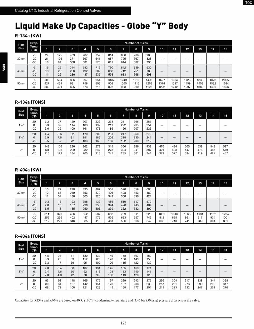
TOC
Catalog C12, Industrial Refrigeration Control Valves
126
HE
Vs
Liquid Make Up Capacities - Globe “Y” BodyR-134a (KW)
R-134a (TONS)
R-404a (KW)
R-404a (TONS)
Port
Size
Evap.
Temp.
(˚C)
Number of Turns
1 2 3 4 5 6 7 8 9 10 11 12 13 14 15
32mm-5-20-30
242118
12510694
439371330
707597531
759641570
814687611
858725644
908767682
980828736
— — — — —
40mm-5-20-30
151311
292522
314266236
582492437
713602535
790668593
842712633
889751668
930785698
— — — — —
50mm-5-20-30
506427380
534451401
806681605
897758673
954806716
1075908807
12491055938
13181113990
149512631123
162713741222
165413971242
172614591297
183815531380
187215821406
200516941506
Port
Size
Evap.
Temp.
(˚F)
Number of Turns
1 2 3 4 5 6 7 8 9 10 11 12 13 14 15
11⁄4”200
-20
7.26.35.6
373229
129114100
207183161
222197173
238211186
251222196
266235207
287254223
— — — — —
11⁄2”200
-20
4.43.93.5
8.67.66.7
928172
170151133
209185163
231205180
247218192
260230203
272241212
— — — — —
2”200
-20
148131115
156138122
236209184
262232205
279247218
315278245
366324285
386341301
438387341
476421371
484428377
505447394
538476419
548485427
587519457
Port
Size
Evap.
Temp.
(˚C)
Number of Turns
1 2 3 4 5 6 7 8 9 10 11 12 13 14 15
32mm-5-20-30
151211
776354
270219188
435353303
467379326
501406349
528428368
559453390
603489421
— — — — —
40mm-5-20-30
9.37.66.5
181513
193157135
358290250
439356306
486394339
519420362
547443382
572464399
— — — — —
50mm-5-20-30
311252217
329266229
496402346
552447385
587476410
662536461
769623536
811657566
920746642
1001812698
1018825710
1063861741
1131917789
1152934804
12341001861
Port
Size
Evap.
Temp.
(˚F)
Number of Turns
1 2 3 4 5 6 7 8 9 10 11 12 13 14 15
11⁄4”200
-20
4.53.93.3
232017
816959
13011295
139120102
149128109
158136115
167143122
180155132
— — — — —
11⁄2”200
-20
2.82.42.0
5.44.64.0
585042
1079278
13111396
145125106
155133113
163140120
171147125
— — — — —
2”200
-20
938068
988472
148127108
165142121
175151128
197170145
229197168
242208177
275236201
299257219
304261223
317273232
338290247
344296252
368317270
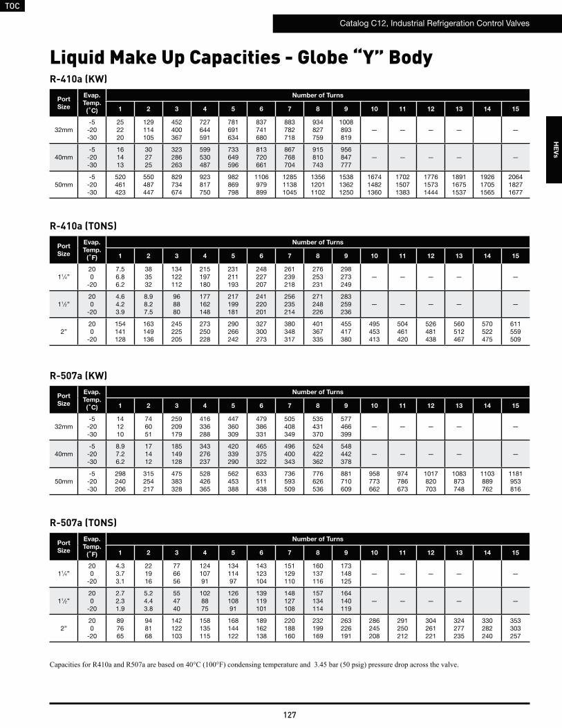
TOC
Catalog C12, Industrial Refrigeration Control Valves
127
HE
Vs
Liquid Make Up Capacities - Globe “Y” BodyR-410a (KW)
R-410a (TONS)
R-507a (KW)
R-507a (TONS)
Port
Size
Evap.
Temp.
(˚C)
Number of Turns
1 2 3 4 5 6 7 8 9 10 11 12 13 14 15
32mm-5-20-30
252220
129114105
452400367
727644591
781691634
837741680
883782718
934827759
1008893819
— — — — —
40mm-5-20-30
161413
302725
323286263
599530487
733649596
813720661
867768704
915810743
956847777
— — — — —
50mm-5-20-30
520461423
550487447
829734674
923817750
982869798
1106979899
128511381045
135612011102
153813621250
167414821360
170215071383
177615731444
189116751537
192617051565
206418271677
Port
Size
Evap.
Temp.
(˚F)
Number of Turns
1 2 3 4 5 6 7 8 9 10 11 12 13 14 15
11⁄4”200
-20
7.56.86.2
383532
134122112
215197180
231211193
248227207
261239218
276253231
298273249
— — — — —
11⁄2”200
-20
4.64.23.9
8.98.27.5
968880
177162148
217199181
241220201
256235214
271248226
283259236
— — — — —
2”200
-20
154141128
163149136
245225205
273250228
290266242
327300273
380348317
401367335
455417380
495453413
504461420
526481438
560512467
570522475
611559509
Port
Size
Evap.
Temp.
(˚C)
Number of Turns
1 2 3 4 5 6 7 8 9 10 11 12 13 14 15
32mm-5-20-30
141210
746051
259209179
416336288
447360309
479386331
505408349
535431370
577466399
— — — — —
40mm-5-20-30
8.97.26.2
171412
185149128
343276237
420339290
465375322
496400343
524422362
548442378
— — — — —
50mm-5-20-30
298240206
315254217
475383328
528426365
562453388
633511438
736593509
776626536
881710609
958773662
974786673
1017820703
1083873748
1103889762
1181953816
Port
Size
Evap.
Temp.
(˚F)
Number of Turns
1 2 3 4 5 6 7 8 9 10 11 12 13 14 15
11⁄4”200
-20
4.33.73.1
221916
776656
12410791
13411497
143123104
151129110
160137116
173148125
— — — — —
11⁄2”200
-20
2.72.31.9
5.24.43.8
554740
1028875
12610891
139119101
148127108
157134114
164140119
— — — — —
2”200
-20
897665
948168
142122103
158135115
168144122
189162138
220188160
232199169
263226191
286245208
291250212
304261221
324277235
330282240
353303257
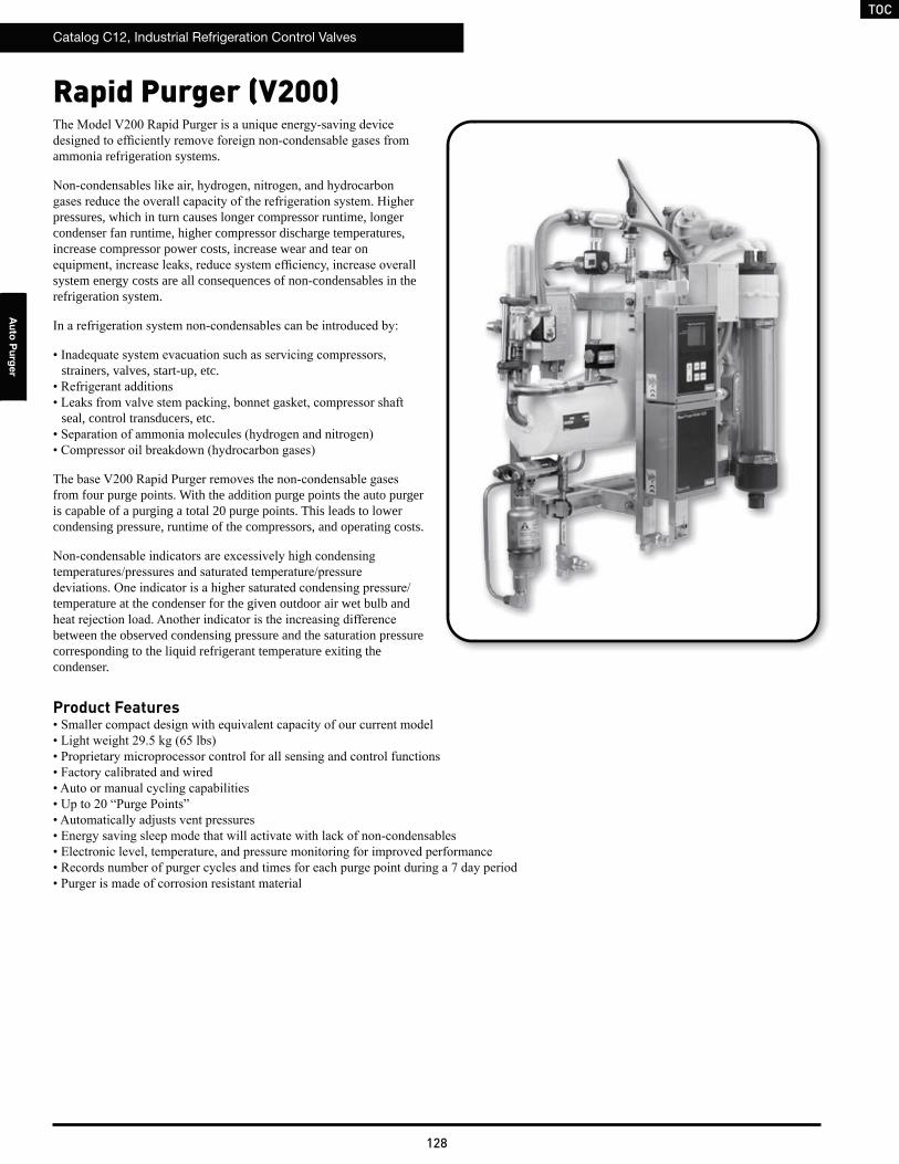
TOC
Catalog C12, Industrial Refrigeration Control Valves
128
Au
to P
urg
er
Rapid Purger (V200)
Product Features
ammonia refrigeration systems.
pressures, which in turn causes longer compressor runtime, longer condenser fan runtime, higher compressor discharge temperatures, increase compressor power costs, increase wear and tear on
system energy costs are all consequences of non-condensables in the refrigeration system.
strainers, valves, start-up, etc.
seal, control transducers, etc.
from four purge points. With the addition purge points the auto purger is capable of a purging a total 20 purge points. This leads to lower condensing pressure, runtime of the compressors, and operating costs.
temperature at the condenser for the given outdoor air wet bulb and
between the observed condensing pressure and the saturation pressure corresponding to the liquid refrigerant temperature exiting the condenser.
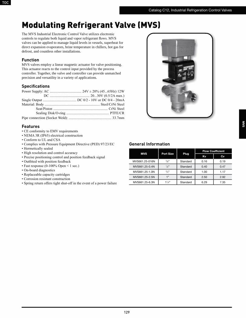
TOC
Catalog C12, Industrial Refrigeration Control Valves
129
MV
S
Modulating Refrigerant Valve (MVS)
valves can be applied to manage liquid levels in vessels, superheat for direct expansion evaporators, brine temperature in chillers, hot gas for defrost, and countless other installations.
FunctionMVS valves employ a linear magnetic actuator for valve positioning. This actuator reacts to the control input provided by the process controller. Together, the valve and controller can provide unmatched precision and versatility in a variety of applications.
SpecificationsPower Supply: A
Pipe connection (Soc
Features
General Information
MVS Port Size PlugFlow Coefficient
Kv Cv
MVS661.25-016N 3 ⁄8” Standard 0.16 0.19
MVS661.25-0.4N 1⁄2” Standard 0.40 0.47
MVS661.25-1.0N 3 ⁄4” Standard 1.00 1.17
MVS661.25-2.5N 1” Standard 2.50 2.92
MVS661.25-6.3N 11⁄4” Standard 6.29 7.35
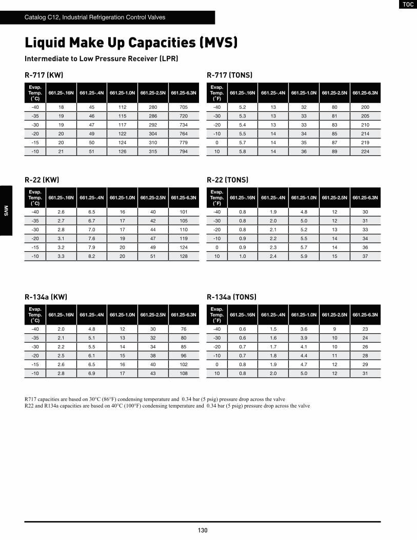
TOC
Catalog C12, Industrial Refrigeration Control Valves
130
MV
S
Liquid Make Up Capacities (MVS)
R-717 (KW)Evap.
Temp.
(˚C)
661.25-.16N 661.25-.4N 661.25-1.0N 661.25-2.5N 661.25-6.3N
-40 18 45 112 280 705
-35 19 46 115 286 720
-30 19 47 117 292 734
-20 20 49 122 304 764
-15 20 50 124 310 779
-10 21 51 126 315 794
R-717 (TONS)Evap.
Temp.
(˚F)
661.25-.16N 661.25-.4N 661.25-1.0N 661.25-2.5N 661.25-6.3N
-40 5.2 13 32 80 200
-30 5.3 13 33 81 205
-20 5.4 13 33 83 210
-10 5.5 14 34 85 214
0 5.7 14 35 87 219
10 5.8 14 36 89 224
Intermediate to Low Pressure Receiver (LPR)
R-22 (KW)Evap.
Temp.
(˚C)
661.25-.16N 661.25-.4N 661.25-1.0N 661.25-2.5N 661.25-6.3N
-40 2.6 6.5 16 40 101
-35 2.7 6.7 17 42 105
-30 2.8 7.0 17 44 110
-20 3.1 7.6 19 47 119
-15 3.2 7.9 20 49 124
-10 3.3 8.2 20 51 128
R-22 (TONS)Evap.
Temp.
(˚F)
661.25-.16N 661.25-.4N 661.25-1.0N 661.25-2.5N 661.25-6.3N
-40 0.8 1.9 4.8 12 30
-30 0.8 2.0 5.0 12 31
-20 0.8 2.1 5.2 13 33
-10 0.9 2.2 5.5 14 34
0 0.9 2.3 5.7 14 36
10 1.0 2.4 5.9 15 37
R-134a (KW)Evap.
Temp.
(˚C)
661.25-.16N 661.25-.4N 661.25-1.0N 661.25-2.5N 661.25-6.3N
-40 2.0 4.8 12 30 76
-35 2.1 5.1 13 32 80
-30 2.2 5.5 14 34 85
-20 2.5 6.1 15 38 96
-15 2.6 6.5 16 40 102
-10 2.8 6.9 17 43 108
R-134a (TONS)Evap.
Temp.
(˚F)
661.25-.16N 661.25-.4N 661.25-1.0N 661.25-2.5N 661.25-6.3N
-40 0.6 1.5 3.6 9 23
-30 0.6 1.6 3.9 10 24
-20 0.7 1.7 4.1 10 26
-10 0.7 1.8 4.4 11 28
0 0.8 1.9 4.7 12 29
10 0.8 2.0 5.0 12 31
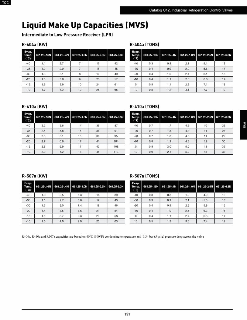
TOC
Catalog C12, Industrial Refrigeration Control Valves
131
MV
S
Liquid Make Up Capacities (MVS)
R-404a (KW)Evap.
Temp.
(˚C)
661.25-.16N 661.25-.4N 661.25-1.0N 661.25-2.5N 661.25-6.3N
-40 1.1 2.7 7 17 42
-35 1.2 2.9 7 18 45
-30 1.3 3.1 8 19 49
-20 1.5 3.6 9 23 57
-15 1.6 3.9 10 24 61
-10 1.7 4.2 10 26 65
R-404a (TONS)Evap.
Temp.
(˚F)
661.25-.16N 661.25-.4N 661.25-1.0N 661.25-2.5N 661.25-6.3N
-40 0.3 0.8 2.1 5.1 13
-30 0.4 0.9 2.2 5.6 14
-20 0.4 1.0 2.4 6.1 15
-10 0.4 1.1 2.6 6.6 17
0 0.5 1.1 2.9 7.1 18
10 0.5 1.2 3.1 7.7 19
Intermediate to Low Pressure Receiver (LPR)
R-410a (KW)Evap.
Temp.
(˚C)
661.25-.16N 661.25-.4N 661.25-1.0N 661.25-2.5N 661.25-6.3N
-40 2.2 5.6 14 35 87
-35 2.4 5.8 14 36 91
-30 2.5 6.1 15 38 95
-20 2.7 6.6 17 41 104
-15 2.8 6.9 17 43 108
-10 2.9 7.2 18 45 113
R-410a (TONS)Evap.
Temp.
(˚F)
661.25-.16N 661.25-.4N 661.25-1.0N 661.25-2.5N 661.25-6.3N
-40 0.7 1.7 4.2 10 26
-30 0.7 1.8 4.4 11 28
-20 0.7 1.8 4.6 11 29
-10 0.8 1.9 4.8 12 30
0 0.8 2.0 5.0 13 32
10 0.9 2.1 5.3 13 33
R-507a (KW)Evap.
Temp.
(˚C)
661.25-.16N 661.25-.4N 661.25-1.0N 661.25-2.5N 661.25-6.3N
-40 1.0 2.5 6.3 16 39
-35 1.1 2.7 6.8 17 43
-30 1.2 3.0 7.4 18 46
-20 1.4 3.5 8.6 21 54
-15 1.5 3.7 9.3 23 58
-10 1.6 4.0 9.9 25 63
R-507a (TONS)Evap.
Temp.
(˚F)
661.25-.16N 661.25-.4N 661.25-1.0N 661.25-2.5N 661.25-6.3N
-40 0.3 0.8 1.9 4.9 12
-30 0.3 0.9 2.1 5.3 13
-20 0.4 0.9 2.3 5.8 15
-10 0.4 1.0 2.5 6.3 16
0 0.4 1.1 2.7 6.8 17
10 0.5 1.2 3.0 7.4 19
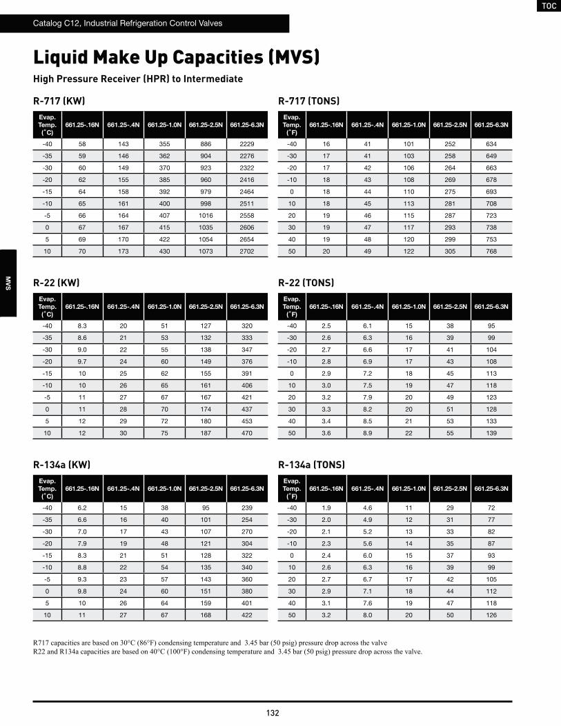
TOC
Catalog C12, Industrial Refrigeration Control Valves
132
MV
S
Liquid Make Up Capacities (MVS)
R-717 (KW)Evap.
Temp.
(˚C)
661.25-.16N 661.25-.4N 661.25-1.0N 661.25-2.5N 661.25-6.3N
-40 58 143 355 886 2229
-35 59 146 362 904 2276
-30 60 149 370 923 2322
-20 62 155 385 960 2416
-15 64 158 392 979 2464
-10 65 161 400 998 2511
-5 66 164 407 1016 2558
0 67 167 415 1035 2606
5 69 170 422 1054 2654
10 70 173 430 1073 2702
R-717 (TONS)Evap.
Temp.
(˚F)
661.25-.16N 661.25-.4N 661.25-1.0N 661.25-2.5N 661.25-6.3N
-40 16 41 101 252 634
-30 17 41 103 258 649
-20 17 42 106 264 663
-10 18 43 108 269 678
0 18 44 110 275 693
10 18 45 113 281 708
20 19 46 115 287 723
30 19 47 117 293 738
40 19 48 120 299 753
50 20 49 122 305 768
R-22 (KW)Evap.
Temp.
(˚C)
661.25-.16N 661.25-.4N 661.25-1.0N 661.25-2.5N 661.25-6.3N
-40 8.3 20 51 127 320
-35 8.6 21 53 132 333
-30 9.0 22 55 138 347
-20 9.7 24 60 149 376
-15 10 25 62 155 391
-10 10 26 65 161 406
-5 11 27 67 167 421
0 11 28 70 174 437
5 12 29 72 180 453
10 12 30 75 187 470
R-22 (TONS)Evap.
Temp.
(˚F)
661.25-.16N 661.25-.4N 661.25-1.0N 661.25-2.5N 661.25-6.3N
-40 2.5 6.1 15 38 95
-30 2.6 6.3 16 39 99
-20 2.7 6.6 17 41 104
-10 2.8 6.9 17 43 108
0 2.9 7.2 18 45 113
10 3.0 7.5 19 47 118
20 3.2 7.9 20 49 123
30 3.3 8.2 20 51 128
40 3.4 8.5 21 53 133
50 3.6 8.9 22 55 139
R-134a (KW)Evap.
Temp.
(˚C)
661.25-.16N 661.25-.4N 661.25-1.0N 661.25-2.5N 661.25-6.3N
-40 6.2 15 38 95 239
-35 6.6 16 40 101 254
-30 7.0 17 43 107 270
-20 7.9 19 48 121 304
-15 8.3 21 51 128 322
-10 8.8 22 54 135 340
-5 9.3 23 57 143 360
0 9.8 24 60 151 380
5 10 26 64 159 401
10 11 27 67 168 422
R-134a (TONS)Evap.
Temp.
(˚F)
661.25-.16N 661.25-.4N 661.25-1.0N 661.25-2.5N 661.25-6.3N
-40 1.9 4.6 11 29 72
-30 2.0 4.9 12 31 77
-20 2.1 5.2 13 33 82
-10 2.3 5.6 14 35 87
0 2.4 6.0 15 37 93
10 2.6 6.3 16 39 99
20 2.7 6.7 17 42 105
30 2.9 7.1 18 44 112
40 3.1 7.6 19 47 118
50 3.2 8.0 20 50 126
High Pressure Receiver (HPR) to Intermediate
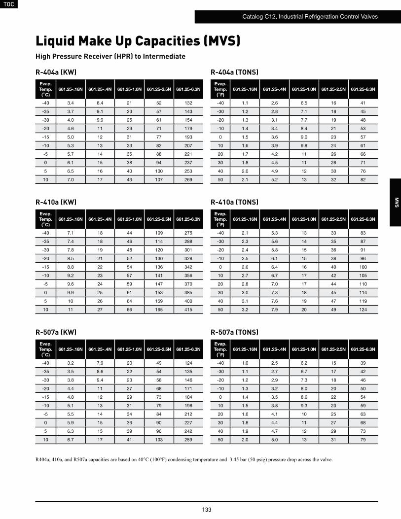
TOC
Catalog C12, Industrial Refrigeration Control Valves
133
MV
S
R-404a (KW)Evap.
Temp.
(˚C)
661.25-.16N 661.25-.4N 661.25-1.0N 661.25-2.5N 661.25-6.3N
-40 3.4 8.4 21 52 132
-35 3.7 9.1 23 57 143
-30 4.0 9.9 25 61 154
-20 4.6 11 29 71 179
-15 5.0 12 31 77 193
-10 5.3 13 33 82 207
-5 5.7 14 35 88 221
0 6.1 15 38 94 237
5 6.5 16 40 100 253
10 7.0 17 43 107 269
R-404a (TONS)Evap.
Temp.
(˚F)
661.25-.16N 661.25-.4N 661.25-1.0N 661.25-2.5N 661.25-6.3N
-40 1.1 2.6 6.5 16 41
-30 1.2 2.8 7.1 18 45
-20 1.3 3.1 7.7 19 48
-10 1.4 3.4 8.4 21 53
0 1.5 3.6 9.0 23 57
10 1.6 3.9 9.8 24 61
20 1.7 4.2 11 26 66
30 1.8 4.5 11 28 71
40 2.0 4.9 12 30 76
50 2.1 5.2 13 32 82
R-410a (KW)Evap.
Temp.
(˚C)
661.25-.16N 661.25-.4N 661.25-1.0N 661.25-2.5N 661.25-6.3N
-40 7.1 18 44 109 275
-35 7.4 18 46 114 288
-30 7.8 19 48 120 301
-20 8.5 21 52 130 328
-15 8.8 22 54 136 342
-10 9.2 23 57 141 356
-5 9.6 24 59 147 370
0 9.9 25 61 153 385
5 10 26 64 159 400
10 11 27 66 165 415
R-410a (TONS)Evap.
Temp.
(˚F)
661.25-.16N 661.25-.4N 661.25-1.0N 661.25-2.5N 661.25-6.3N
-40 2.1 5.3 13 33 83
-30 2.3 5.6 14 35 87
-20 2.4 5.8 15 36 91
-10 2.5 6.1 15 38 96
0 2.6 6.4 16 40 100
10 2.7 6.7 17 42 105
20 2.8 7.0 17 44 110
30 3.0 7.3 18 45 114
40 3.1 7.6 19 47 119
50 3.2 7.9 20 49 124
R-507a (KW)Evap.
Temp.
(˚C)
661.25-.16N 661.25-.4N 661.25-1.0N 661.25-2.5N 661.25-6.3N
-40 3.2 7.9 20 49 124
-35 3.5 8.6 22 54 135
-30 3.8 9.4 23 58 146
-20 4.4 11 27 68 171
-15 4.8 12 29 73 184
-10 5.1 13 31 79 198
-5 5.5 14 34 84 212
0 5.9 15 36 90 227
5 6.3 15 39 96 242
10 6.7 17 41 103 259
R-507a (TONS)Evap.
Temp.
(˚F)
661.25-.16N 661.25-.4N 661.25-1.0N 661.25-2.5N 661.25-6.3N
-40 1.0 2.5 6.2 15 39
-30 1.1 2.7 6.7 17 42
-20 1.2 2.9 7.3 18 46
-10 1.3 3.2 8.0 20 50
0 1.4 3.5 8.6 22 54
10 1.5 3.8 9.3 23 59
20 1.6 4.1 10 25 63
30 1.8 4.4 11 27 68
40 1.9 4.7 12 29 73
50 2.0 5.0 13 31 79
High Pressure Receiver (HPR) to Intermediate
Liquid Make Up Capacities (MVS)
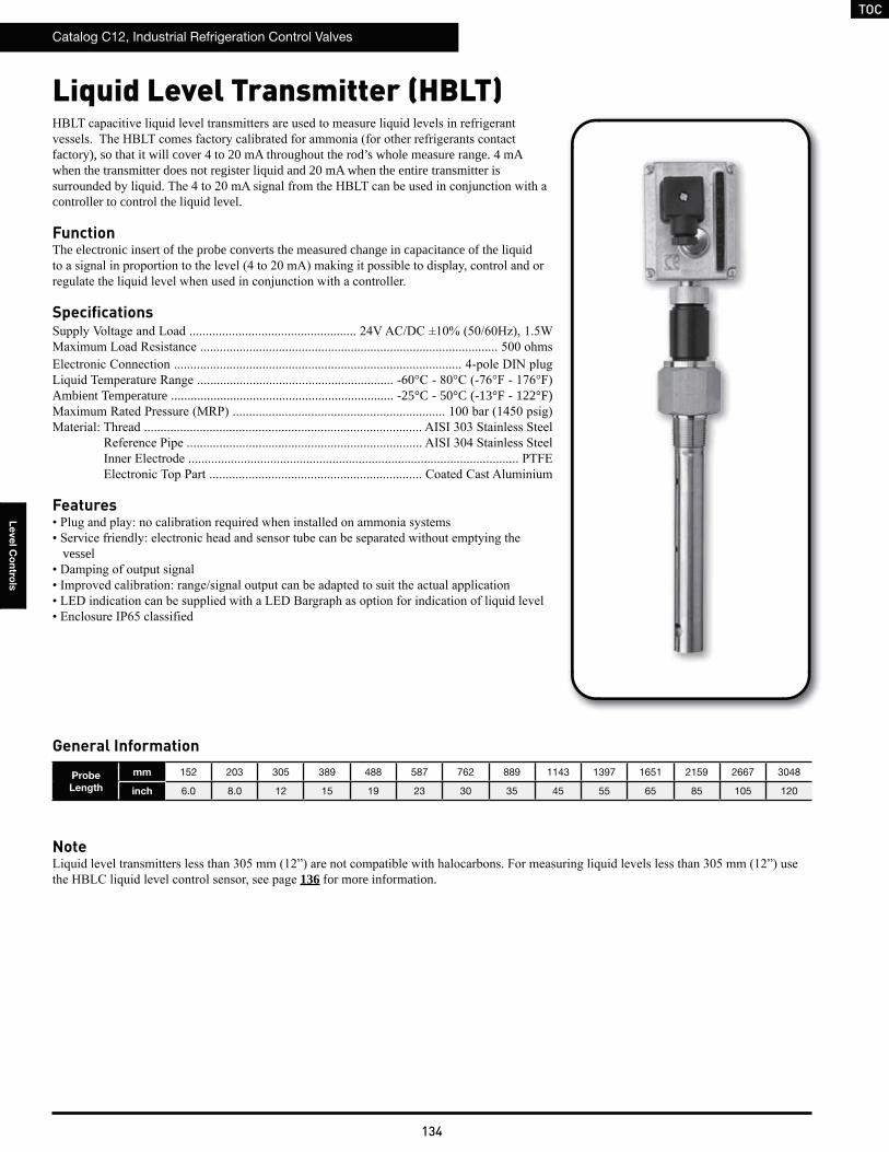
TOC
Catalog C12, Industrial Refrigeration Control Valves
134
Le
ve
l Co
ntro
ls
Liquid Level Transmitter (HBLT)
factory), so that it will cover 4 to 20 mA throughout the rod’s whole measure range. 4 mA when the transmitter does not register liquid and 20 mA when the entire transmitter is
controller to control the liquid level.
FunctionThe electronic insert of the probe converts the measured change in capacitance of the liquid
Specifications
Ambient Temperature .................................................................... -25°C - 50°C (-13°F - 122°F)
Features
vessel
Probe
Length
mm 152 203 305 389 488 587 762 889 1143 1397 1651 2159 2667 3048
inch 6.0 8.0 12 15 19 23 30 35 45 55 65 85 105 120
General Information
Note
136 for more information.
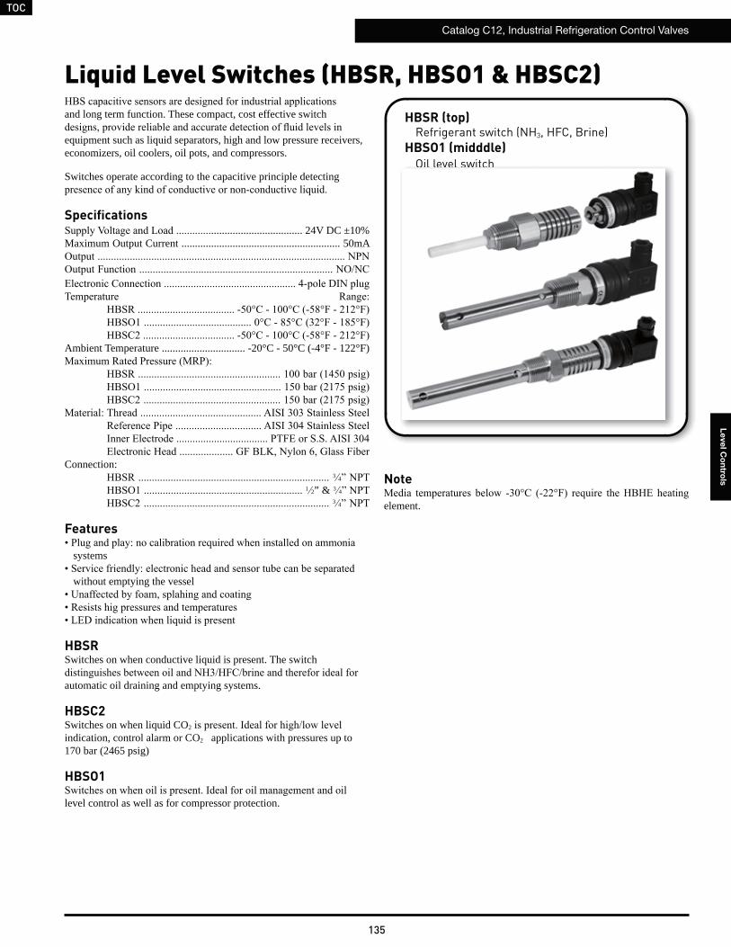
TOC
Catalog C12, Industrial Refrigeration Control Valves
135
Le
ve
l Co
ntro
ls
Liquid Level Switches (HBSR, HBSO1 & HBSC2)
and long term function. These compact, cost effective switch
equipment such as liquid separators, high and low pressure receivers, economizers, oil coolers, oil pots, and compressors.
Switches operate according to the capacitive principle detecting
Specifications.................................. 24V DC ±10%
Maximum Output Current ........................................................... 50mA
Ambient Temperature ............................... -20°C - 50°C (-4°F - 122°F)
Connection:3 4
1 2” & 3 4
3 4
Features
systems
without emptying the vessel
HBSRSwitches on when conductive liquid is present. The switch
automatic oil draining and emptying systems.
HBSC2Switches on when liquid CO2
indication, control alarm or CO2 applications with pressures up to 170 bar (2465 psig)
HBSO1
level control as well as for compressor protection.
HBSR (top)Refrigerant switch (NH3, HFC, Brine)
HBSO1 (midddle)Oil level switch
HBSC2 (bottom)Liquid CO2 switch
Note
element.
Oil level switchHBSC2 (bottom)
Liquid CO2 switch
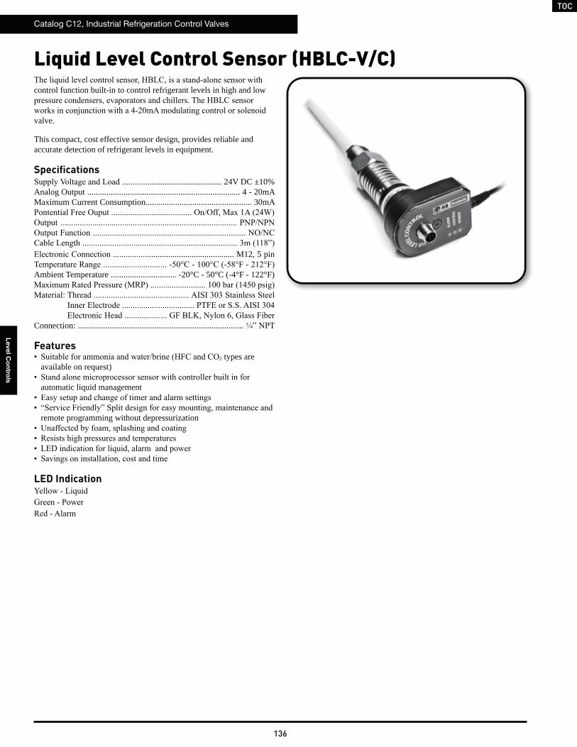
TOC
Catalog C12, Industrial Refrigeration Control Valves
136
Le
ve
l Co
ntro
ls
Liquid Level Control Sensor (HBLC-V/C)
control function built-in to control refrigerant levels in high and low
valve.
This compact, cost effective sensor design, provides reliable and accurate detection of refrigerant levels in equipment.
Specifications.................................. 24V DC ±10%
Analog Output ........................................................................ 4 - 20mAMaximum Current Consumption.................................................. 30mA
........................................ M12, 5 pin
Ambient Temperature ............................... -20°C - 50°C (-4°F - 122°F)
Connection: .............................................................................. 3 4
Features2 types are
available on request)
automatic liquid management
remote programming without depressurization
LED Indication
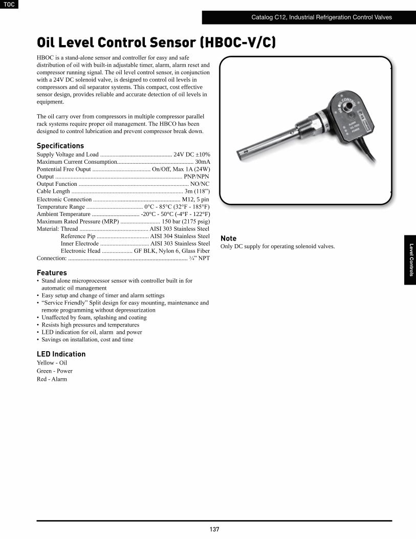
TOC
Catalog C12, Industrial Refrigeration Control Valves
137
Le
ve
l Co
ntro
ls
Oil Level Control Sensor (HBOC-V/C)
with a 24V DC solenoid valve, is designed to control oil levels in compressors and oil separator systems. This compact, cost effective sensor design, provides reliable and accurate detection of oil levels in equipment.
The oil carry over from compressors in multiple compressor parallel
Specifications.................................. 24V DC ±10%
Maximum Current Consumption.................................................. 30mA
........................................ M12, 5 pin
Ambient Temperature ............................... -20°C - 50°C (-4°F - 122°F)
Connection: .............................................................................. 3 4
Features
automatic oil management
remote programming without depressurization
LED IndicationYellow - Oil
NoteOnly DC supply for operating solenoid valves.
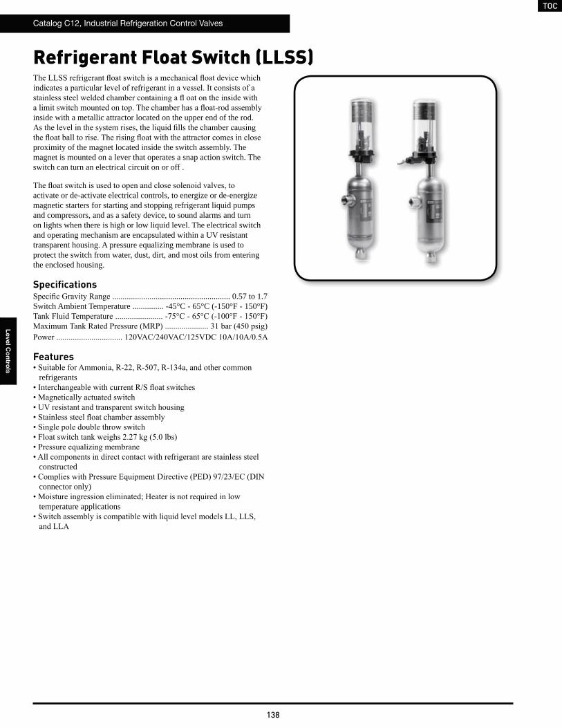
TOC
Catalog C12, Industrial Refrigeration Control Valves
138
Le
ve
l Co
ntro
ls
Refrigerant Float Switch (LLSS)
inside with a metallic attractor located on the upper end of the rod.
proximity of the magnet located inside the switch assembly. The magnet is mounted on a lever that operates a snap action switch. The switch can turn an electrical circuit on or off .
activate or de-activate electrical controls, to energize or de-energize magnetic starters for starting and stopping refrigerant liquid pumps and compressors, and as a safety device, to sound alarms and turn on lights when there is high or low liquid level. The electrical switch and operating mechanism are encapsulated within a UV resistant transparent housing. A pressure equalizing membrane is used to protect the switch from water, dust, dirt, and most oils from entering the enclosed housing.
Specifications.................................. 0.57 to 1.7
Switch Ambient Temperature ............... -45°C - 65°C (-150°F - 150°F)
Features
refrigerants
constructed
connector only)
temperature applications
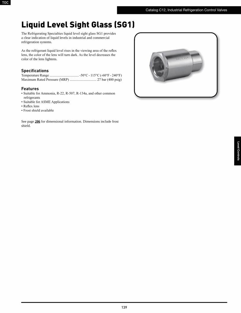
TOC
Catalog C12, Industrial Refrigeration Control Valves
139
Le
ve
l Co
ntro
ls
Liquid Level Sight Glass (SG1)
a clear indication of liquid levels in industrial and commercial refrigeration systems.
color of the lens lightens.
Specifications
Features
refrigerants
See page 206 for dimensional information. Dimensions include frost shield.
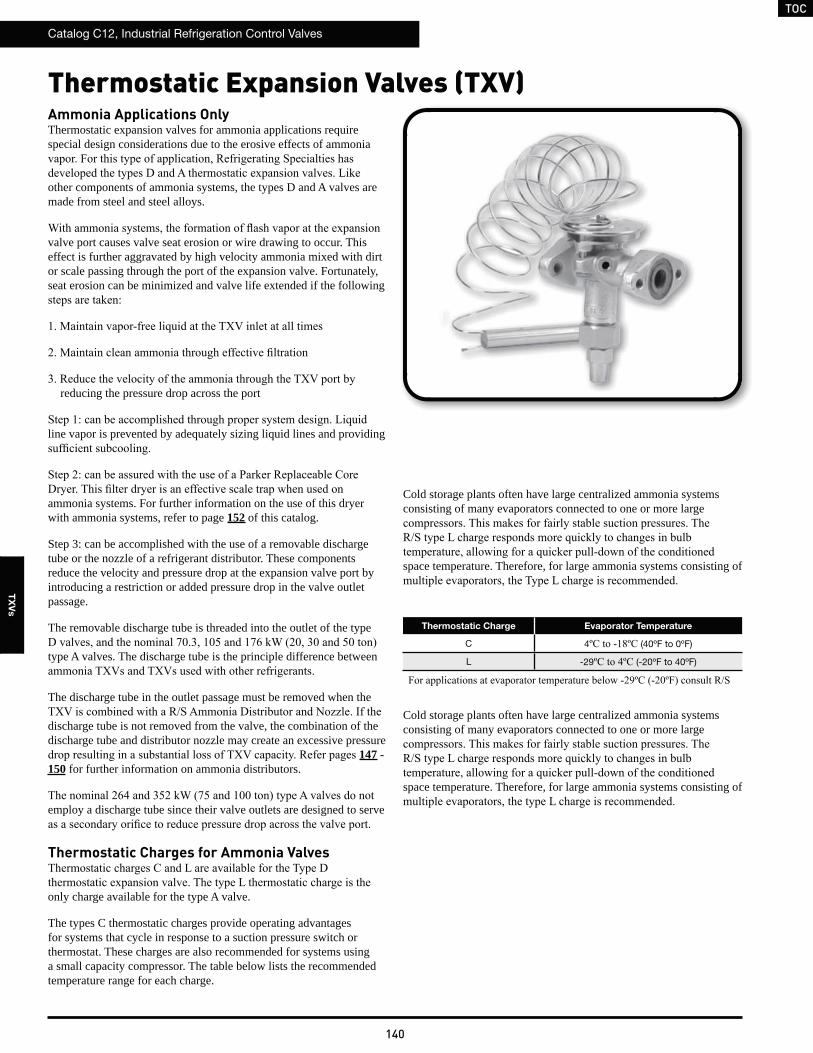
TOC
Catalog C12, Industrial Refrigeration Control Valves
140
TX
Vs
Ammonia Applications OnlyThermostatic expansion valves for ammonia applications require special design considerations due to the erosive effects of ammonia
other components of ammonia systems, the types D and A valves are made from steel and steel alloys.
valve port causes valve seat erosion or wire drawing to occur. This effect is further aggravated by high velocity ammonia mixed with dirt or scale passing through the port of the expansion valve. Fortunately, seat erosion can be minimized and valve life extended if the following
reducing the pressure drop across the port
line vapor is prevented by adequately sizing liquid lines and providing
ammonia systems. For further information on the use of this dryer with ammonia systems, refer to page 152 of this catalog.
Step 3: can be accomplished with the use of a removable discharge tube or the nozzle of a refrigerant distributor. These components reduce the velocity and pressure drop at the expansion valve port by introducing a restriction or added pressure drop in the valve outlet passage.
The removable discharge tube is threaded into the outlet of the type
type A valves. The discharge tube is the principle difference between
The discharge tube in the outlet passage must be removed when the
discharge tube is not removed from the valve, the combination of the discharge tube and distributor nozzle may create an excessive pressure
147 - 150 for further information on ammonia distributors.
employ a discharge tube since their valve outlets are designed to serve
Thermostatic Charges for Ammonia Valves
only charge available for the type A valve.
The types C thermostatic charges provide operating advantages for systems that cycle in response to a suction pressure switch or thermostat. These charges are also recommended for systems using a small capacity compressor. The table below lists the recommended temperature range for each charge.
Thermostatic Expansion Valves (TXV)
Cold storage plants often have large centralized ammonia systems consisting of many evaporators connected to one or more large
space temperature. Therefore, for large ammonia systems consisting of
Cold storage plants often have large centralized ammonia systems consisting of many evaporators connected to one or more large
space temperature. Therefore, for large ammonia systems consisting of
Thermostatic Charge Evaporator Temperature
C 4 (40ºF to 0ºF)
L -29 (-20ºF to 40ºF)
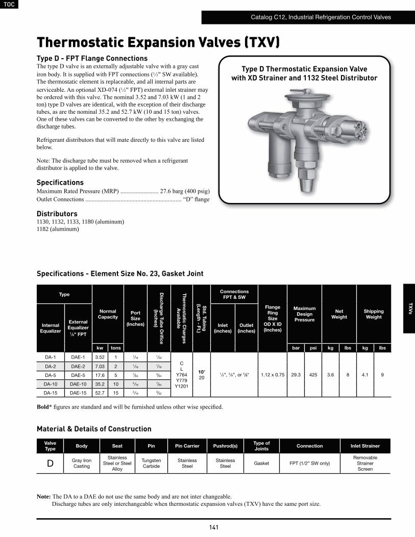
TOC
Catalog C12, Industrial Refrigeration Control Valves
141
TX
Vs
Thermostatic Expansion Valves (TXV)Type D - FPT Flange Connections
1 2” SW available). The thermostatic element is replaceable, and all internal parts are
1 2” FPT) external inlet strainer may
ton) type D valves are identical, with the exception of their discharge
One of these valves can be converted to the other by exchanging the discharge tubes.
below.
distributor is applied to the valve.
Specifications
Distributors1130, 1132, 1133, 1180 (aluminum)1182 (aluminum)
Type D Thermostatic Expansion Valvewith XD Strainer and 1132 Steel Distributor
Specifications - Element Size No. 23, Gasket Joint
Material & Details of Construction
Type
Normal
Capacity Port
Size
(Inches)
Dis
ch
arg
e T
ub
e O
rific
e
(Inc
he
s)
Th
erm
osta
tic C
ha
rge
s
Ava
ilab
le
Std
. Tu
bin
g
(Le
ng
th - F
t.)
Connections
FPT & SW
Flange
Ring
Size
OD X ID
(Inches)
Maximum
Design
Pressure
Net
Weight
Shipping
Weight
Internal
Equalizer
External
Equalizer 1 ⁄8” FPT
Inlet
(inches)
Outlet
(inches)
kw tons bar psi kg lbs kg lbs
DA-1 DAE-1 3.52 1 1⁄161 ⁄32
CL
Y764Y779
Y1201
10*20
1⁄4”, 3 ⁄8”, or 1 ⁄2* 1.12 x 0.75 29.3 425 3.6 8 4.1 9
DA-2 DAE-2 7.03 2 1⁄161⁄16
DA-5 DAE-5 17.6 5 7⁄645⁄64
DA-10 DAE-10 35.2 10 3 ⁄167⁄64
DA-15 DAE-15 52.7 15 3 ⁄165⁄32
Note:
Valve
TypeBody Seat Pin Pin Carrier Pushrod(s)
Type of
JointsConnection Inlet Strainer
D Gray Iron Casting
Stainless Steel or Steel
Alloy
Tungsten Carbide
Stainless Steel
Stainless Steel
Gasket FPT (1/2” SW only)Removable
Strainer Screen
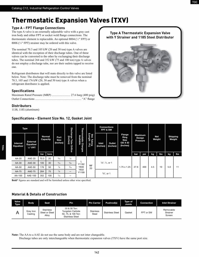
TOC
Catalog C12, Industrial Refrigeration Control Valves
142
TX
Vs
Type
Normal
Capacity Port
Size
(Inches)
Dis
ch
arg
e T
ub
e O
rific
e
(Inc
he
s)
Th
erm
osta
tic C
ha
rge
s
Ava
ilab
le
Std
. Tu
bin
g
(Le
ng
th - F
t.)
Connections
FPT & SW
Flange
Ring
Size
OD X ID
(Inches)
Maximum
Design
Pressure
Net
Weight
Shipping
Weight
Internal
Equalizer
External
Equalizer 1 ⁄8” FPT
Inlet
(inches)
Outlet
(inches)
kw tons bar psi kg lbs kg lbs
AA-20 AAE-20 70.3 20 5⁄161 ⁄8
LY1182Y830Y832Y1199
10*20
1 ⁄2*, 3 ⁄4, or 1
1.75 x 1.25 27.6 400 4.5 10 5.0 11
AA-30 AAE-30 105 30 5⁄165⁄32
AA-50 AAE-50 176 50 3 ⁄8 3⁄16
AA-75 AAE-75 264 75 3 ⁄8 —3 ⁄4*, or 1
AA-100 AAE-100 352 100 7⁄16 —
Valve
TypeBody Seat Pin Pin Carrier Pushrod(s)
Type of
JointsConnection Inlet Strainer
A Gray Iron Casting
Stainless Steel or Steel
Alloy
20 & 30 Ton: Tungsten Carbide50, 75, & 100 Ton:
Stainless Steel
Stainless Steel
Stainless Steel Gasket FPT or SWRemovable
Strainer Screen
Type A - FPT Flange Connections
thermostatic element is replaceable. An optional 8004 (1 2” FPT) or 8006 (3 4” FPT) strainer may be ordered with this valve.
identical with the exception of their discharge tubes. One of these valves can be converted to the other by exchanging their discharge
do not employ a discharge tube, nor are their outlets tapped to receive one.
refrigerant distributor is applied.
Specifications
Distributors1138, 1185 (aluminum)
Thermostatic Expansion Valves (TXV)
Type A Thermostatic Expansion Valvewith Y Strainer and 1185 Steel Distributor
Specifications - Element Size No. 12, Gasket Joint
Material & Details of Construction
Note:
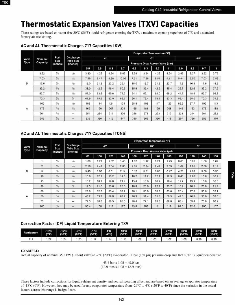
TOC
Catalog C12, Industrial Refrigeration Control Valves
143
TX
Vs
factory air test setting.
Valve
Type
Nominal
Capacity
Port
Size
(inches)
Discharge
Tube Size
(inches)
Evaporator Temperature (ºF)
40º 20º 5º
Pressure Drop Across Valve (psi)
80 100 120 140 100 120 140 160 100 120 140 160
D
1 1⁄161 ⁄32 1.08 1.21 1.32 1.43 1.02 1.12 1.21 1.29 0.85 0.93 1.00 1.07
2 1⁄161⁄16 2.16 2.41 2.64 2.86 2.05 2.24 2.42 2.59 1.69 1.85 2.00 2.14
5 7⁄645⁄64 5.40 6.03 6.61 7.14 5.12 5.61 6.05 6.47 4.23 4.63 5.00 5.35
10 3⁄167⁄64 10.8 12.1 13.2 14.3 10.2 11.2 12.1 12.9 8.45 9.26 10.0 10.7
15 3⁄165⁄32 16.2 18.1 19.8 21.4 15.4 16.8 18.2 19.4 12.7 13.9 15.0 16.0
A
20 5⁄161 ⁄8 19.3 21.6 23.6 25.5 18.8 20.6 22.2 23.7 16.9 18.5 20.0 21.4
30 5⁄165⁄32 28.9 32.3 35.4 38.2 28.1 30.8 33.3 35.6 25.4 27.8 30.0 32.1
50 3 ⁄8 3⁄16 48.2 53.9 59.0 63.7 46.9 51.4 55.5 59.3 42.3 46.3 50.0 53.5
75 3 ⁄8 — 72.3 80.8 88.5 95.6 70.4 77.1 83.3 89.0 63.4 69.4 75.0 80.2
100 7⁄16 — 96.4 108 118 127 93.8 103 111 119 84.5 92.6 100 107
Thermostatic Expansion Valves (TXV) Capacities
AC and AL Thermostatic Charges 717 Capacities (TONS)
Valve
Type
Nominal
Capacity
Port
Size
(inches)
Discharge
Tube Size
(inches)
Evaporator Temperature (ºC)
4º -7º -15º
Pressure Drop Across Valve (bar)
5.5 6.9 8.3 9.7 6.9 8.3 9.7 11 6.9 8.3 9.7 11
D
3.52 1⁄161 ⁄32 3.80 4.25 4.64 5.03 3.59 3.94 4.25 4.54 2.99 3.27 3.52 3.76
7.03 1⁄161⁄16 7.59 8.47 9.28 10.06 7.21 7.88 8.51 9.11 5.94 6.50 7.03 7.52
17.6 7⁄645⁄64 19.0 21.2 23.2 25.1 18.0 19.7 21.3 22.7 14.9 16.3 17.6 18.8
35.2 3⁄167⁄64 38.0 42.5 46.4 50.3 35.9 39.4 42.5 45.4 29.7 32.6 35.2 37.6
52.7 3⁄165⁄32 57.0 63.6 69.6 75.2 54.1 59.1 64.0 68.2 44.7 48.9 52.7 56.3
A
70.3 5⁄161 ⁄8 67.9 75.9 83.0 89.7 66.1 72.4 78.1 83.3 59.4 65.0 70.3 75.2
105 5⁄165⁄32 102 114 124 134 98.8 108 117 125 89.3 97.7 105 113
176 3 ⁄8 3⁄16 169 190 207 224 165 181 195 208 149 163 176 188
264 3 ⁄8 — 254 284 311 336 248 271 293 313 223 244 264 282
352 7⁄16 — 339 380 415 447 330 362 390 418 297 326 352 376
AC and AL Thermostatic Charges 717 Capacities (KW)
Refrigerant-18ºC
(0ºF)
-12ºC
(10ºF)
-7ºC
(20ºF)
-1ºC
(30ºF)
4ºC
(40ºf)
10ºC
(50ºF)
16ºC
(60ºF)
21ºC
(70ºF)
27ºC
(80ºF)
30ºC
(86ºC)
32ºC
(90ºF)
38ºC
(100ºF)
717 1.27 1.24 1.20 1.17 1.14 1.11 1.08 1.05 1.02 1.00 0.99 0.96
45.4 bar x 1.08 = 49.0 bar(12.9 tons x 1.08 = 13.9 tons)
Correction Factor (CF) Liquid Temperature Entering TXV
These factors include corrections for liquid refrigerant density and net refrigerating effect and are based on an average evaporator temperature
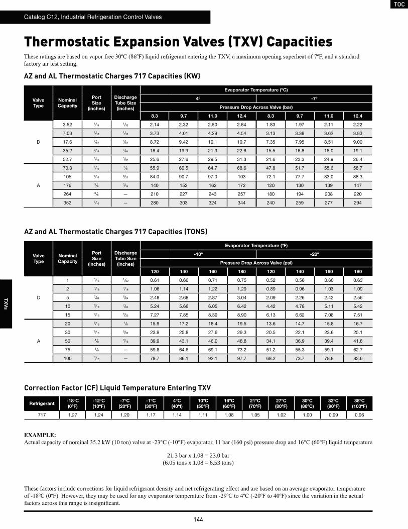
TOC
Catalog C12, Industrial Refrigeration Control Valves
144
TX
Vs
Valve
Type
Nominal
Capacity
Port
Size
(inches)
Discharge
Tube Size
(inches)
Evaporator Temperature (ºC)
4º -7º
Pressure Drop Across Valve (bar)
8.3 9.7 11.0 12.4 8.3 9.7 11.0 12.4
D
3.52 1⁄161 ⁄32 2.14 2.32 2.50 2.64 1.83 1.97 2.11 2.22
7.03 1⁄161⁄16 3.73 4.01 4.29 4.54 3.13 3.38 3.62 3.83
17.6 7⁄645⁄64 8.72 9.42 10.1 10.7 7.35 7.95 8.51 9.00
35.2 3⁄167⁄64 18.4 19.9 21.3 22.6 15.5 16.8 18.0 19.1
52.7 3⁄165⁄32 25.6 27.6 29.5 31.3 21.6 23.3 24.9 26.4
A
70.3 5⁄161 ⁄8 55.9 60.5 64.7 68.6 47.8 51.7 55.6 58.7
105 5⁄165⁄32 84.0 90.7 97.0 103 72.1 77.7 83.0 88.3
176 3 ⁄8 3⁄16 140 152 162 172 120 130 139 147
264 3 ⁄8 — 210 227 243 257 180 194 208 220
352 7⁄16 — 280 303 324 344 240 259 277 294
Refrigerant-18ºC
(0ºF)
-12ºC
(10ºF)
-7ºC
(20ºF)
-1ºC
(30ºF)
4ºC
(40ºf)
10ºC
(50ºF)
16ºC
(60ºF)
21ºC
(70ºF)
27ºC
(80ºF)
30ºC
(86ºC)
32ºC
(90ºF)
38ºC
(100ºF)
717 1.27 1.24 1.20 1.17 1.14 1.11 1.08 1.05 1.02 1.00 0.99 0.96
AZ and AL Thermostatic Charges 717 Capacities (KW)
Correction Factor (CF) Liquid Temperature Entering TXV
21.3 bar x 1.08 = 23.0 bar(6.05 tons x 1.08 = 6.53 tons)
factory air test setting.
Valve
Type
Nominal
Capacity
Port
Size
(inches)
Discharge
Tube Size
(inches)
Evaporator Temperature (ºF)
-10º -20º
Pressure Drop Across Valve (psi)
120 140 160 180 120 140 160 180
D
1 1⁄161 ⁄32 0.61 0.66 0.71 0.75 0.52 0.56 0.60 0.63
2 1⁄161⁄16 1.06 1.14 1.22 1.29 0.89 0.96 1.03 1.09
5 7⁄645⁄64 2.48 2.68 2.87 3.04 2.09 2.26 2.42 2.56
10 3⁄167⁄64 5.24 5.66 6.05 6.42 4.42 4.78 5.11 5.42
15 3⁄165⁄32 7.27 7.85 8.39 8.90 6.13 6.62 7.08 7.51
A
20 5⁄161 ⁄8 15.9 17.2 18.4 19.5 13.6 14.7 15.8 16.7
30 5⁄165⁄32 23.9 25.8 27.6 29.3 20.5 22.1 23.6 25.1
50 3 ⁄8 3⁄16 39.9 43.1 46.0 48.8 34.1 36.9 39.4 41.8
75 3 ⁄8 — 59.8 64.6 69.1 73.2 51.2 55.3 59.1 62.7
100 7⁄16 — 79.7 86.1 92.1 97.7 68.2 73.7 78.8 83.6
AZ and AL Thermostatic Charges 717 Capacities (TONS)
These factors include corrections for liquid refrigerant density and net refrigerating effect and are based on an average evaporator temperature
Thermostatic Expansion Valves (TXV) Capacities
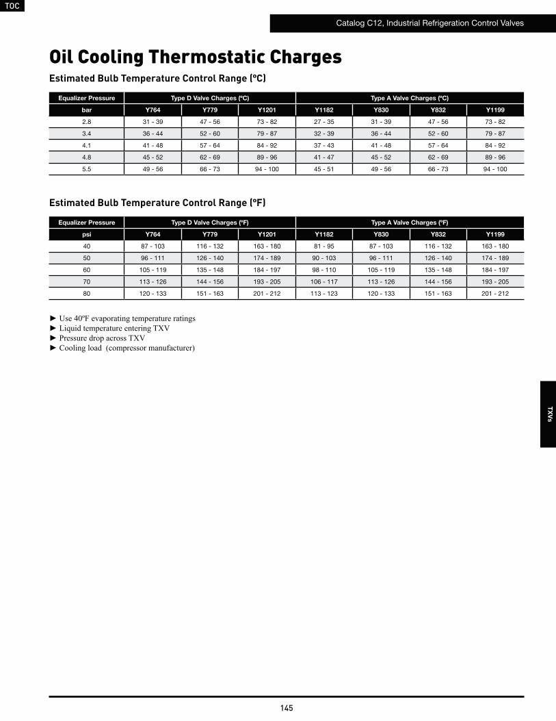
TOC
Catalog C12, Industrial Refrigeration Control Valves
145
TX
Vs
Estimated Bulb Temperature Control Range (ºC)
Oil Cooling Thermostatic Charges
Estimated Bulb Temperature Control Range (ºF)
Equalizer Pressure Type D Valve Charges (ºC) Type A Valve Charges (ºC)
bar Y764 Y779 Y1201 Y1182 Y830 Y832 Y1199
2.8 31 - 39 47 - 56 73 - 82 27 - 35 31 - 39 47 - 56 73 - 82
3.4 36 - 44 52 - 60 79 - 87 32 - 39 36 - 44 52 - 60 79 - 87
4.1 41 - 48 57 - 64 84 - 92 37 - 43 41 - 48 57 - 64 84 - 92
4.8 45 - 52 62 - 69 89 - 96 41 - 47 45 - 52 62 - 69 89 - 96
5.5 49 - 56 66 - 73 94 - 100 45 - 51 49 - 56 66 - 73 94 - 100
Equalizer Pressure Type D Valve Charges (ºF) Type A Valve Charges (ºF)
psi Y764 Y779 Y1201 Y1182 Y830 Y832 Y1199
40 87 - 103 116 - 132 163 - 180 81 - 95 87 - 103 116 - 132 163 - 180
50 96 - 111 126 - 140 174 - 189 90 - 103 96 - 111 126 - 140 174 - 189
60 105 - 119 135 - 148 184 - 197 98 - 110 105 - 119 135 - 148 184 - 197
70 113 - 126 144 - 156 193 - 205 106 - 117 113 - 126 144 - 156 193 - 205
80 120 - 133 151 - 163 201 - 212 113 - 123 120 - 133 151 - 163 201 - 212
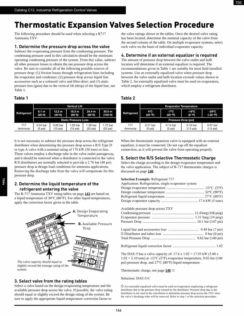
TOC
Catalog C12, Industrial Refrigeration Control Valves
146
TX
Vs
1. Determine the pressure drop across the valveSubtract the evaporating pressure from the condensing pressure. The condensing pressure used in this calculation should be the minimum operating condensing pressure of the system. From this value, subtract all other pressure losses to obtain the net pressure drop across the valve. Be sure to consider all of the following possible sources of pressure drop: (1) friction losses through refrigeration lines including the evaporator and condenser; (2) pressure drop across liquid line
pressure loss (gain) due to the vertical lift (drop) of the liquid line, see Table 1.
These valves employ a discharge tube in the valve outlet passageway, and it should be removed when a distributor is connected to the valve.
pressure drop at design load conditions for ammonia applications.
pressure drop.
2. Determine the liquid temperature of the refrigerant entering the valve
143 are based on a liquid temperature of 30°C (86°F). For other liquid temperatures, apply the correction factor given in the table.
3. Select valve from the rating tablesSelect a valve based on the design evaporating temperature and the
should equal or slightly exceed the design rating of the system. Be sure to apply the appropriate liquid temperature correction factor to
the valve ratings shown in the tables. Once the desired valve rating has been located, determine the nominal capacity of the valve from the second column of the table. On multiple evaporator systems, select each valve on the basis of individual evaporator capacity.
4. Determine if an external equalizer is requiredThe amount of pressure drop between the valve outlet and bulb location will determine if an external equalizer is required. The
systems. Use an externally equalized valve when pressure drop between the valve outlet and bulb location exceeds values shown in Table 2. An externally equalized valve must be used on evaporators, which employ a refrigerant distributor.
When the thermostatic expansion valve is equipped with an external equalizer, it must be connected. Do not cap off the equalizer connection, as it will prevent the valve from operating properly.
5. Select the R/S Selective Thermostatic ChargeSelect the charge according to the design evaporator temperature and
discussed on page 140.
Design evaporator temperature .......................................... -15°C (5°F)Design condenser temperature ........................................... 32°C (90°F)
Condensing pressure ............................................... 11.4 barg (166 psig)
Pressure Drop ............................................................ 10.1 bar (147 psi)
1 Distributor and tubes loss ............................................. 0 bar (0 psi)Total Pressure Drop ................................................. 9.65 bar (140 psi)
1.02 = 5.10 tons) at -15°C (5°F) evaporator temperature, 9.65 bar (140 psi) pressure drop, and 27°C (80°F) liquid temperature.
Thermostatic charge, see page 140: C
1 An externally equalized valve must be used on evaporators employing a refrigerant distributor due to the pressure drop created by the distributor. Pressure drop due to the
Refrigerant
Vertical Lift
6.1 m
(20 ft)
12.2 m
(40 ft)
18.3 m
(60 ft)
24.4 m
(80 ft)
30.5 m
(100 ft)
Static Pressure Loss
717 Ammonia
0.34 bar(5 psi)
0.69 bar(10 psi)
1.03 bar(15 psi)
1.38 bar(20 psi)
1.72 bar(25 psi)
Refrigerant
Evaporator Temperature
4ºC
(40 ºF)
-7ºC
(20 ºF)
-18ºC
(0 ºF)
-29ºC
(-20 ºF)
Pressure Drop (psi)
717 Ammonia
0.21 bar(3 psi)
0.14 bar(2 psi)
0.10 bar(1.5 psi)
0.07 bar(1.0 psi)
Thermostatic Expansion Valves Selection Procedure
Table 1 Table 2
EVAPORATOR TEMPE
20°
SSURE DROP ACROSS V
120 140
160
0.93 1.00 1.07
1.85 2.00 2.14
4.63 5.00 5.35
9.26 10.0 10.7CAPACITY (tons)EVAPORATING TEMPCondensing Temp. (°F)
80° 3.1 5.2 7.2 90° 2.8 5.0 6.9100° 2.5 4.7 6.6
0° 5° 10°
A. Design Evaporating Temperature
B. Available Pressure Drop
The valve capacity should equal or slightly exceed the tonnage rating of the system.
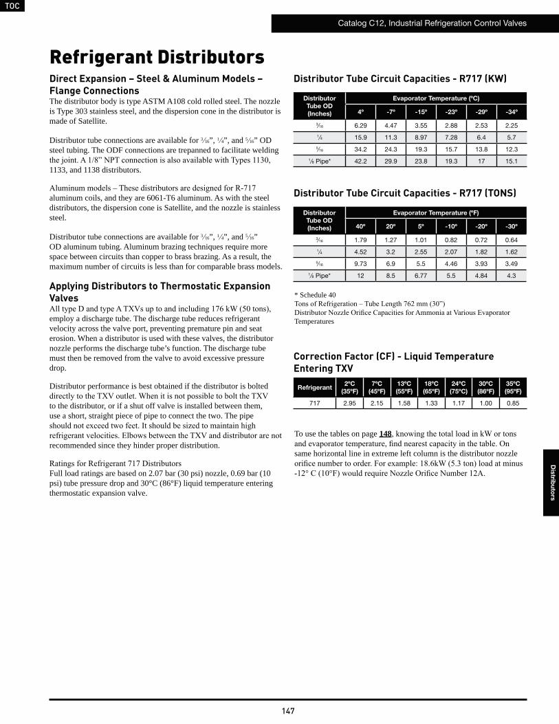
TOC
Catalog C12, Industrial Refrigeration Control Valves
147
Dis
tribu
tors
Refrigerant DistributorsDirect Expansion – Steel & Aluminum Models – Flange ConnectionsThe distributor body is type ASTM A108 cold rolled steel. The nozzle is Type 303 stainless steel, and the dispersion cone in the distributor is made of Satellite.
Distributor tube connections are available for 3 16”, 1 4”, and 5 16” OD steel tubing. The ODF connections are trepanned to facilitate welding
1133, and 1138 distributors.
aluminum coils, and they are 6061-T6 aluminum. As with the steel distributors, the dispersion cone is Satellite, and the nozzle is stainless steel.
Distributor tube connections are available for 3 16”, 1 4”, and 5 16” OD aluminum tubing. Aluminum brazing techniques require more space between circuits than copper to brass brazing. As a result, the maximum number of circuits is less than for comparable brass models.
Applying Distributors to Thermostatic Expansion Valves
employ a discharge tube. The discharge tube reduces refrigerant velocity across the valve port, preventing premature pin and seat erosion. When a distributor is used with these valves, the distributor nozzle performs the discharge tube’s function. The discharge tube must then be removed from the valve to avoid excessive pressure drop.
Distributor performance is best obtained if the distributor is bolted
to the distributor, or if a shut off valve is installed between them, use a short, straight piece of pipe to connect the two. The pipe
recommended since they hinder proper distribution.
Full load ratings are based on 2.07 bar (30 psi) nozzle, 0.69 bar (10 psi) tube pressure drop and 30°C (86°F) liquid temperature entering thermostatic expansion valve.
Distributor Tube Circuit Capacities - R717 (TONS)
To use the tables on page 148
same horizontal line in extreme left column is the distributor nozzle
Refrigerant2ºC
(35ºF)
7ºC
(45ºF)
13ºC
(55ºF)
18ºC
(65ºF)
24ºC
(75ºC)
30ºC
(86ºF)
35ºC
(95ºF)
717 2.95 2.15 1.58 1.33 1.17 1.00 0.85
Correction Factor (CF) - Liquid Temperature Entering TXV
Distributor Tube Circuit Capacities - R717 (KW)
* Schedule 40
Temperatures
Distributor
Tube OD
(Inches)
Evaporator Temperature (ºC)
4º -7º -15º -23º -29º -34º
3⁄16 6.29 4.47 3.55 2.88 2.53 2.25
1⁄4 15.9 11.3 8.97 7.28 6.4 5.7
5⁄16 34.2 24.3 19.3 15.7 13.8 12.3
1⁄8 Pipe* 42.2 29.9 23.8 19.3 17 15.1
Distributor
Tube OD
(Inches)
Evaporator Temperature (ºF)
40º 20º 5º -10º -20º -30º
3⁄16 1.79 1.27 1.01 0.82 0.72 0.64
1⁄4 4.52 3.2 2.55 2.07 1.82 1.62
5⁄16 9.73 6.9 5.5 4.46 3.93 3.49
1⁄8 Pipe* 12 8.5 6.77 5.5 4.84 4.3
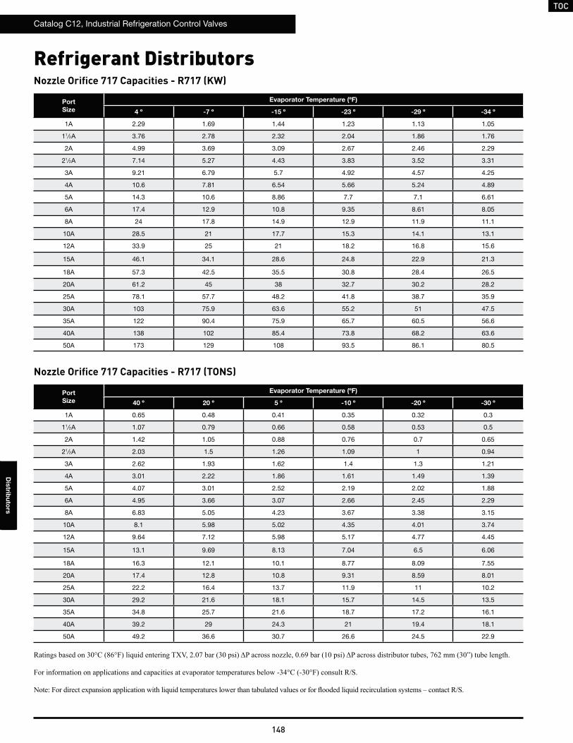
TOC
Catalog C12, Industrial Refrigeration Control Valves
148
Dis
tribu
tors
Refrigerant Distributors
Nozzle Orifice 717 Capacities - R717 (TONS)
Nozzle Orifice 717 Capacities - R717 (KW)
Port
Size
Evaporator Temperature (ºF)
40 º 20 º 5 º -10 º -20 º -30 º
1A 0.65 0.48 0.41 0.35 0.32 0.3
11⁄2A 1.07 0.79 0.66 0.58 0.53 0.5
2A 1.42 1.05 0.88 0.76 0.7 0.65
21⁄2A 2.03 1.5 1.26 1.09 1 0.94
3A 2.62 1.93 1.62 1.4 1.3 1.21
4A 3.01 2.22 1.86 1.61 1.49 1.39
5A 4.07 3.01 2.52 2.19 2.02 1.88
6A 4.95 3.66 3.07 2.66 2.45 2.29
8A 6.83 5.05 4.23 3.67 3.38 3.15
10A 8.1 5.98 5.02 4.35 4.01 3.74
12A 9.64 7.12 5.98 5.17 4.77 4.45
15A 13.1 9.69 8.13 7.04 6.5 6.06
18A 16.3 12.1 10.1 8.77 8.09 7.55
20A 17.4 12.8 10.8 9.31 8.59 8.01
25A 22.2 16.4 13.7 11.9 11 10.2
30A 29.2 21.6 18.1 15.7 14.5 13.5
35A 34.8 25.7 21.6 18.7 17.2 16.1
40A 39.2 29 24.3 21 19.4 18.1
50A 49.2 36.6 30.7 26.6 24.5 22.9
Port
Size
Evaporator Temperature (ºF)
4 º -7 º -15 º -23 º -29 º -34 º
1A 2.29 1.69 1.44 1.23 1.13 1.05
11⁄2A 3.76 2.78 2.32 2.04 1.86 1.76
2A 4.99 3.69 3.09 2.67 2.46 2.29
21⁄2A 7.14 5.27 4.43 3.83 3.52 3.31
3A 9.21 6.79 5.7 4.92 4.57 4.25
4A 10.6 7.81 6.54 5.66 5.24 4.89
5A 14.3 10.6 8.86 7.7 7.1 6.61
6A 17.4 12.9 10.8 9.35 8.61 8.05
8A 24 17.8 14.9 12.9 11.9 11.1
10A 28.5 21 17.7 15.3 14.1 13.1
12A 33.9 25 21 18.2 16.8 15.6
15A 46.1 34.1 28.6 24.8 22.9 21.3
18A 57.3 42.5 35.5 30.8 28.4 26.5
20A 61.2 45 38 32.7 30.2 28.2
25A 78.1 57.7 48.2 41.8 38.7 35.9
30A 103 75.9 63.6 55.2 51 47.5
35A 122 90.4 75.9 65.7 60.5 56.6
40A 138 102 85.4 73.8 68.2 63.6
50A 173 129 108 93.5 86.1 80.5
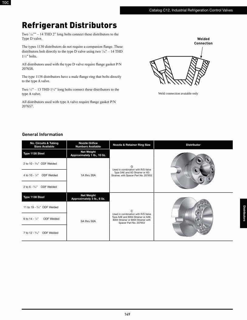
TOC
Catalog C12, Industrial Refrigeration Control Valves
149
Dis
tribu
tors
Two 7 16
Type D valve.
distributors bolt directly to the type D valve using two 7 16
11 2” bolts.
207658.
to the type A valve.
Two 1 2 3 4” long bolts connect these distributors to the type A valve.
207657.
No. Circuits & Tubing
Sizes Available
Nozzle Orifice
Numbers AvailableNozzle & Retainer Ring Size Distributor
Type 1130 SteelNet Weight
Approximately 1 lb., 10 0z.
GUsed in combination with R/S Valve
Type DAE and XD Strainer or XD Strainer, with Spacer Part No. 207652
2 to 10 - 3⁄16” ODF Welded
1A thru 30A4 to 10 - 1 ⁄4” ODF Welded
2 to 6 - 5⁄16” ODF Welded
Type 1138 SteelNet Weight
Approximately 3 lb., 6 0z.
CUsed in combination with R/S Valve Type AAE and 8004 Strainer or AAE, 8004 Strainer or 8004 Strainer with
Spacer Part No. 207653
11 to 19 - 3⁄16” ODF Welded
5A thru 50A6 to 14 - 1 ⁄4” ODF Welded
7 to 12 - 5⁄16” ODF Welded
Refrigerant Distributors
General Information
Weld connection avaiable only
WeldedConnection
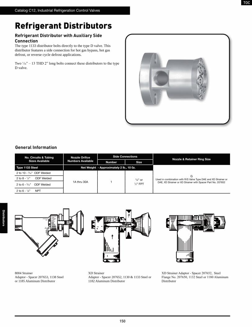
TOC
Catalog C12, Industrial Refrigeration Control Valves
150
Dis
tribu
tors
No. Circuits & Tubing
Sizes Available
Nozzle Orifice
Numbers Available
Side ConnectionsNozzle & Retainer Ring Size
Number Size
Type 1133 Steel Net Weight - Approximately 2 lb., 10 0z.
GUsed in combination with R/S Valve Type DAE and XD Strainer or
DAE, XD Strainer or XD Strainer with Spacer Part No. 207652
2 to 10 - 3⁄16” ODF Welded
1A thru 30A 13 ⁄8” or
1 ⁄2” FPT
2 to 8 - 1 ⁄4” ODF Welded
2 to 6 - 5⁄16” ODF Welded
2 to 6 - 1 ⁄8” NPT
Refrigerant Distributor with Auxiliary Side ConnectionThe type 1133 distributor bolts directly to the type D valve. This distributor features a side connection for hot gas bypass, hot gas defrost, or reverse cycle defrost applications.
Two 7 16
D valve.
8004 Strainer Adaptor - Spacer 207653, 1138 Steel or 1185 Aluminum Distributor
Adaptor - Spacer 207652, 1130 & 1133 Steel or 1182 Aluminum Distributor Distributor
Refrigerant Distributors
General Information
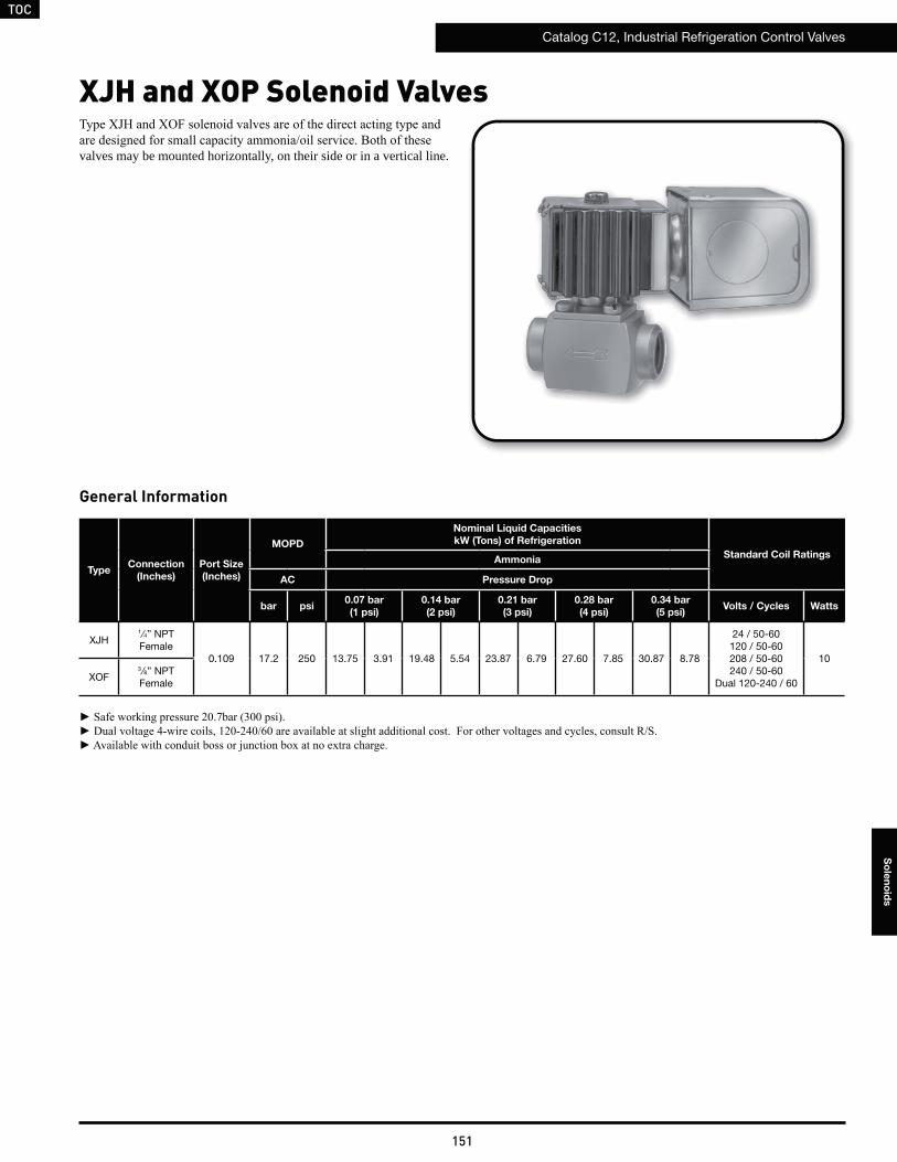
TOC
Catalog C12, Industrial Refrigeration Control Valves
151
So
len
oid
s
TypeConnection
(Inches)
Port Size
(Inches)
MOPD
Nominal Liquid Capacities
kW (Tons) of Refrigeration
Standard Coil RatingsAmmonia
AC Pressure Drop
bar psi0.07 bar
(1 psi)
0.14 bar
(2 psi)
0.21 bar
(3 psi)
0.28 bar
(4 psi)
0.34 bar
(5 psi)Volts / Cycles Watts
XJH1⁄4” NPTFemale
0.109 17.2 250 13.75 3.91 19.48 5.54 23.87 6.79 27.60 7.85 30.87 8.78
24 / 50-60120 / 50-60208 / 50-60240 / 50-60
Dual 120-240 / 60
10
XOF3 ⁄8” NPT Female
valves may be mounted horizontally, on their side or in a vertical line.
XJH and XOP Solenoid Valves
General Information
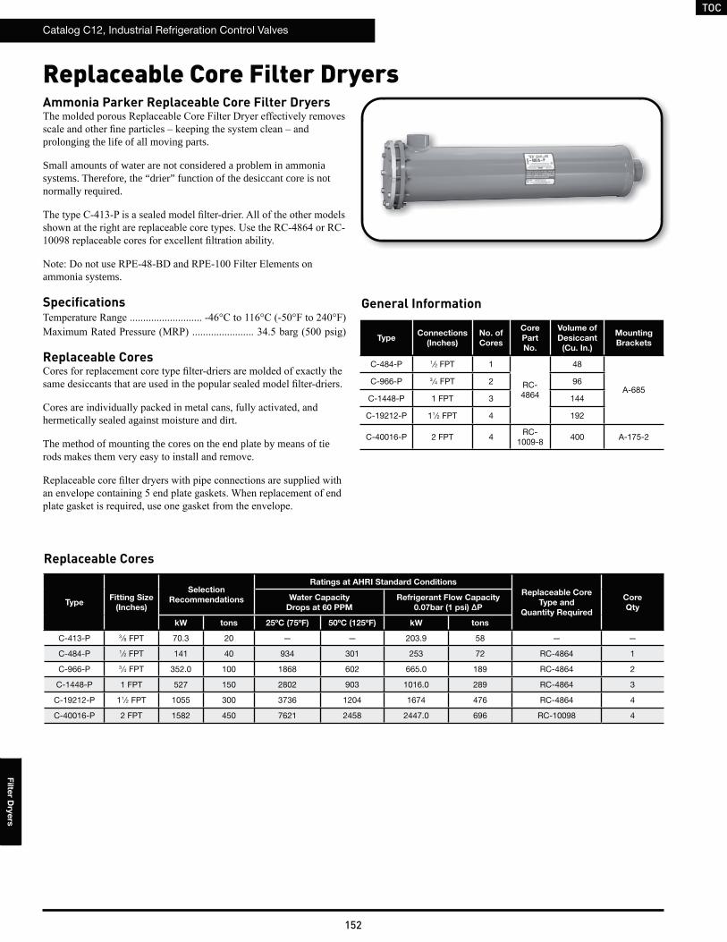
TOC
Catalog C12, Industrial Refrigeration Control Valves
152
Filte
r Dry
ers
Replaceable Core Filter DryersAmmonia Parker Replaceable Core Filter Dryers
prolonging the life of all moving parts.
Small amounts of water are not considered a problem in ammonia systems. Therefore, the “drier” function of the desiccant core is not normally required.
ammonia systems.
Specifications
Replaceable Cores
hermetically sealed against moisture and dirt.
The method of mounting the cores on the end plate by means of tie
TypeConnections
(Inches)
No. of
Cores
Core
Part
No.
Volume of
Desiccant
(Cu. In.)
Mounting
Brackets
C-484-P 1⁄2 FPT 1
RC-4864
48
A-685C-966-P 3 ⁄4 FPT 2 96
C-1448-P 1 FPT 3 144
C-19212-P 11⁄2 FPT 4 192
C-40016-P 2 FPT 4RC-
1009-8400 A-175-2
General Information
Replaceable Cores
TypeFitting Size
(Inches)
Selection
Recommendations
Ratings at AHRI Standard Conditions
Replaceable Core
Type and
Quantity Required
Core
Qty
Water Capacity
Drops at 60 PPM
Refrigerant Flow Capacity
0.07bar (1 psi) ΔP
kW tons 25ºC (75ºF) 50ºC (125ºF) kW tons
C-413-P 3 ⁄8 FPT 70.3 20 — — 203.9 58 — —
C-484-P 1⁄2 FPT 141 40 934 301 253 72 RC-4864 1
C-966-P 3 ⁄4 FPT 352.0 100 1868 602 665.0 189 RC-4864 2
C-1448-P 1 FPT 527 150 2802 903 1016.0 289 RC-4864 3
C-19212-P 11⁄2 FPT 1055 300 3736 1204 1674 476 RC-4864 4
C-40016-P 2 FPT 1582 450 7621 2458 2447.0 696 RC-10098 4
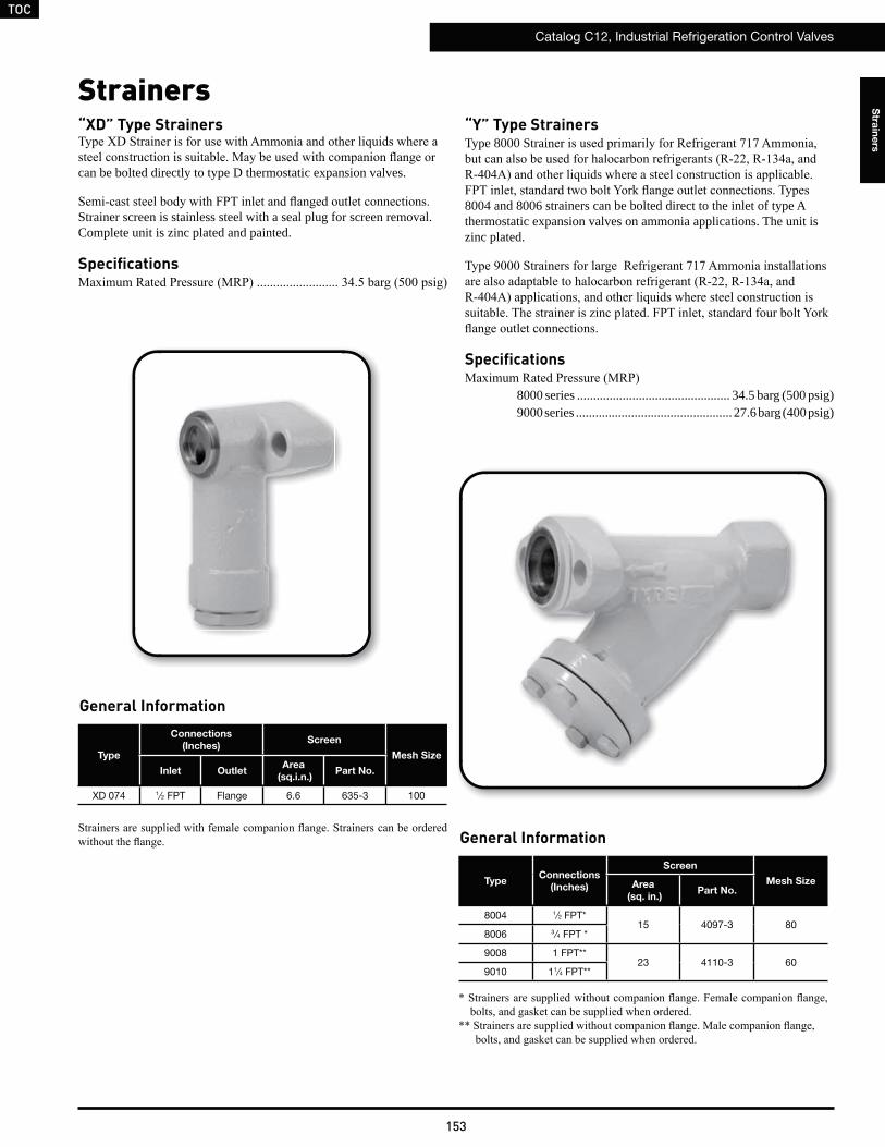
TOC
Catalog C12, Industrial Refrigeration Control Valves
153
Stra
ine
rs
Strainers“XD” Type Strainers
can be bolted directly to type D thermostatic expansion valves.
Strainer screen is stainless steel with a seal plug for screen removal. Complete unit is zinc plated and painted.
Specifications
Type
Connections
(Inches)Screen
Mesh Size
Inlet OutletArea
(sq.i.n.)Part No.
XD 074 1⁄2 FPT Flange 6.6 635-3 100
“Y” Type StrainersType 8000 Strai
8004 and 8006 strainers can be bolted direct to the inlet of type A thermostatic expansion valves on ammonia applications. The unit is zinc plated.
Specifications
8000 series ............................................... 34.5 barg (500 psig)9000 series ................................................ 27.6 barg (400 psig)
TypeConnections
(Inches)
Screen
Mesh SizeArea
(sq. in.)Part No.
8004 1⁄2 FPT*15 4097-3 80
8006 3 ⁄4 FPT *
9008 1 FPT**23 4110-3 60
9010 11⁄4 FPT**
General Information
General Information
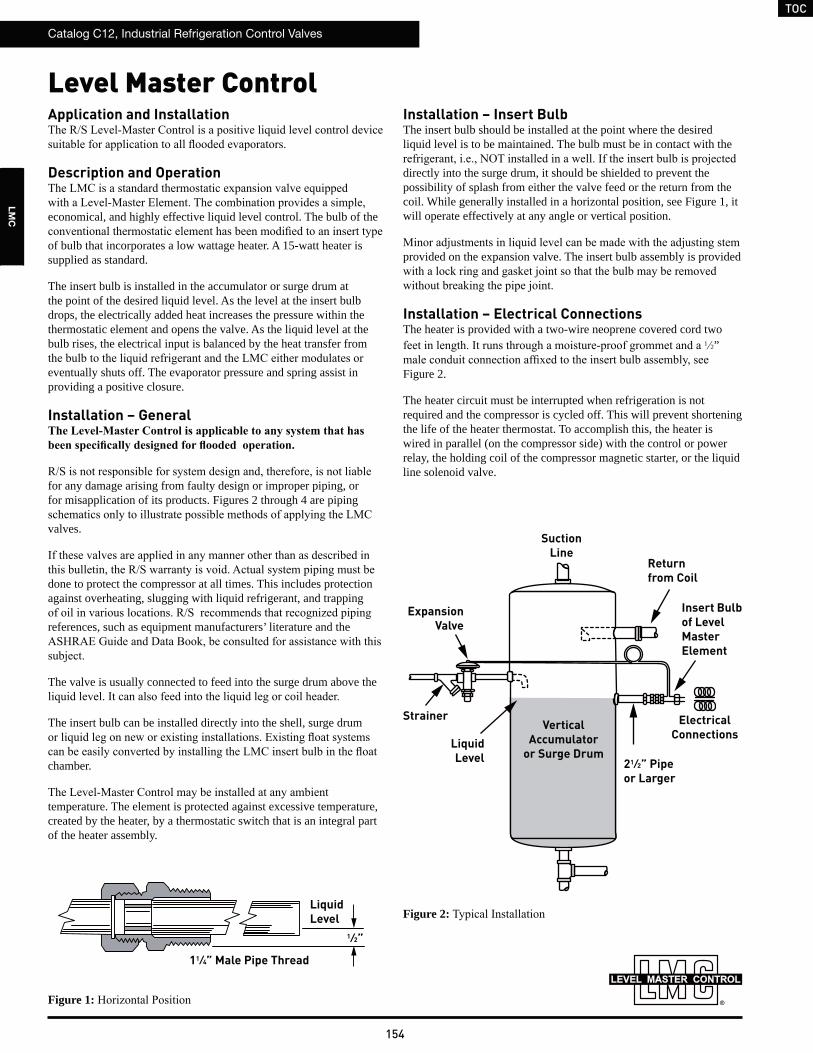
TOC
Catalog C12, Industrial Refrigeration Control Valves
154
LM
C
Level Master ControlApplication and Installation
Description and Operation
economical, and highly effective liquid level control. The bulb of the
of bulb that incorporates a low wattage heater. A 15-watt heater is supplied as standard.
The insert bulb is installed in the accumulator or surge drum at the point of the desired liquid level. As the level at the insert bulb drops, the electrically added heat increases the pressure within the thermostatic element and opens the valve. As the liquid level at the bulb rises, the electrical input is balanced by the heat transfer from
eventually shuts off. The evaporator pressure and spring assist in providing a positive closure.
Installation – General
for any damage arising from faulty design or improper piping, or for misapplication of its products. Figures 2 through 4 are piping
valves.
done to protect the compressor at all times. This includes protection against overheating, slugging with liquid refrigerant, and trapping
references, such as equipment manufacturers’ literature and the
The valve is usually connected to feed into the surge drum above the
The insert bulb can be installed directly into the shell, surge drum
chamber.
temperature. The element is protected against excessive temperature, created by the heater, by a thermostatic switch that is an integral part of the heater assembly.
Installation – Insert BulbThe insert bulb should be installed at the point where the desired liquid level is to be maintained. The bulb must be in contact with the
directly into the surge drum, it should be shielded to prevent the possibility of splash from either the valve feed or the return from the coil. While generally installed in a horizontal position, see Figure 1, it will operate effectively at any angle or vertical position.
provided on the expansion valve. The insert bulb assembly is provided
Installation – Electrical ConnectionsThe heater is provided with a two-wire neoprene covered cord two
1 2”
Figure 2.
The heater circuit must be interrupted when refrigeration is not required and the compressor is cycled off. This will prevent shortening the life of the heater thermostat. To accomplish this, the heater is wired in parallel (on the compressor side) with the control or power relay, the holding coil of the compressor magnetic starter, or the liquid line solenoid valve.
Figure 2:
Figure 1:
Strainer
LiquidLevel
ExpansionValve
VerticalAccumulator
or Surge Drum
SuctionLine
Returnfrom Coil
Insert Bulb of LevelMaster Element
ElectricalConnections
21⁄2” Pipeor Larger
1⁄2”
11⁄4” Male Pipe Thread
LiquidLevel
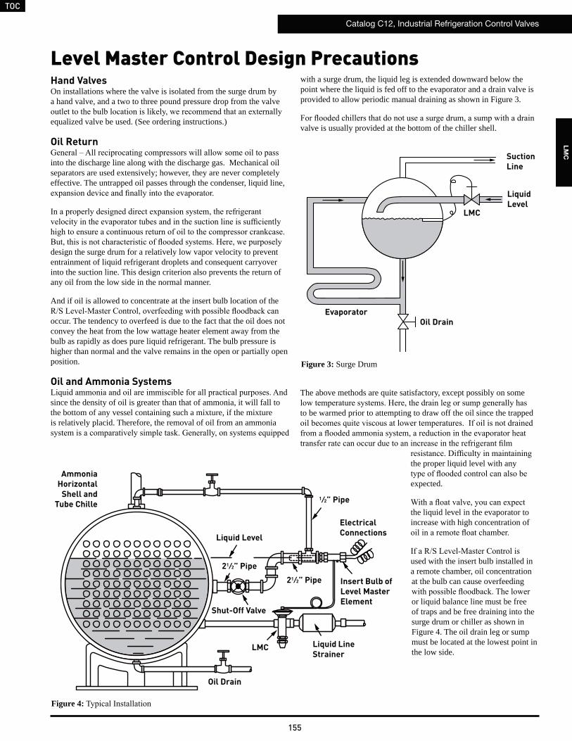
TOC
Catalog C12, Industrial Refrigeration Control Valves
155
LM
C
Hand ValvesOn installations where the valve is isolated from the surge drum by a hand valve, and a two to three pound pressure drop from the valve
equalized valve be used. (See ordering instructions.)
Oil Return
into the discharge line along with the discharge gas. Mechanical oil separators are used extensively; however, they are never completely effective. The untrapped oil passes through the condenser, liquid line,
design the surge drum for a relatively low vapor velocity to prevent entrainment of liquid refrigerant droplets and consequent carryover into the suction line. This design criterion also prevents the return of any oil from the low side in the normal manner.
And if oil is allowed to concentrate at the insert bulb location of the
occur. The tendency to overfeed is due to the fact that the oil does not convey the heat from the low wattage heater element away from the bulb as rapidly as does pure liquid refrigerant. The bulb pressure is higher than normal and the valve remains in the open or partially open position.
Oil and Ammonia Systems
since the density of oil is greater than that of ammonia, it will fall to the bottom of any vessel containing such a mixture, if the mixture is relatively placid. Therefore, the removal of oil from an ammonia
with a surge drum, the liquid leg is extended downward below the point where the liquid is fed off to the evaporator and a drain valve is provided to allow periodic manual draining as shown in Figure 3.
valve is usually provided at the bottom of the chiller shell.
Figure 3: Surge Drum
Figure 4:
Level Master Control Design Precautions
LiquidLevel
SuctionLine
LMC
Oil DrainEvaporator
The above methods are quite satisfactory, except possibly on some
to be warmed prior to attempting to draw off the oil since the trapped
the proper liquid level with any
expected.
the liquid level in the evaporator to increase with high concentration of
used with the insert bulb installed in a remote chamber, oil concentration at the bulb can cause overfeeding
or liquid balance line must be free of traps and be free draining into the surge drum or chiller as shown in Figure 4. The oil drain leg or sump must be located at the lowest point in the low side.
AmmoniaHorizontal
Shell and Tube Chille
Liquid Level
1⁄2” Pipe
Oil Drain
LMC Liquid Line Strainer
Insert Bulb of Level Master Element
ElectricalConnections
21⁄2” Pipe
21⁄2” Pipe
Shut-Off Valve
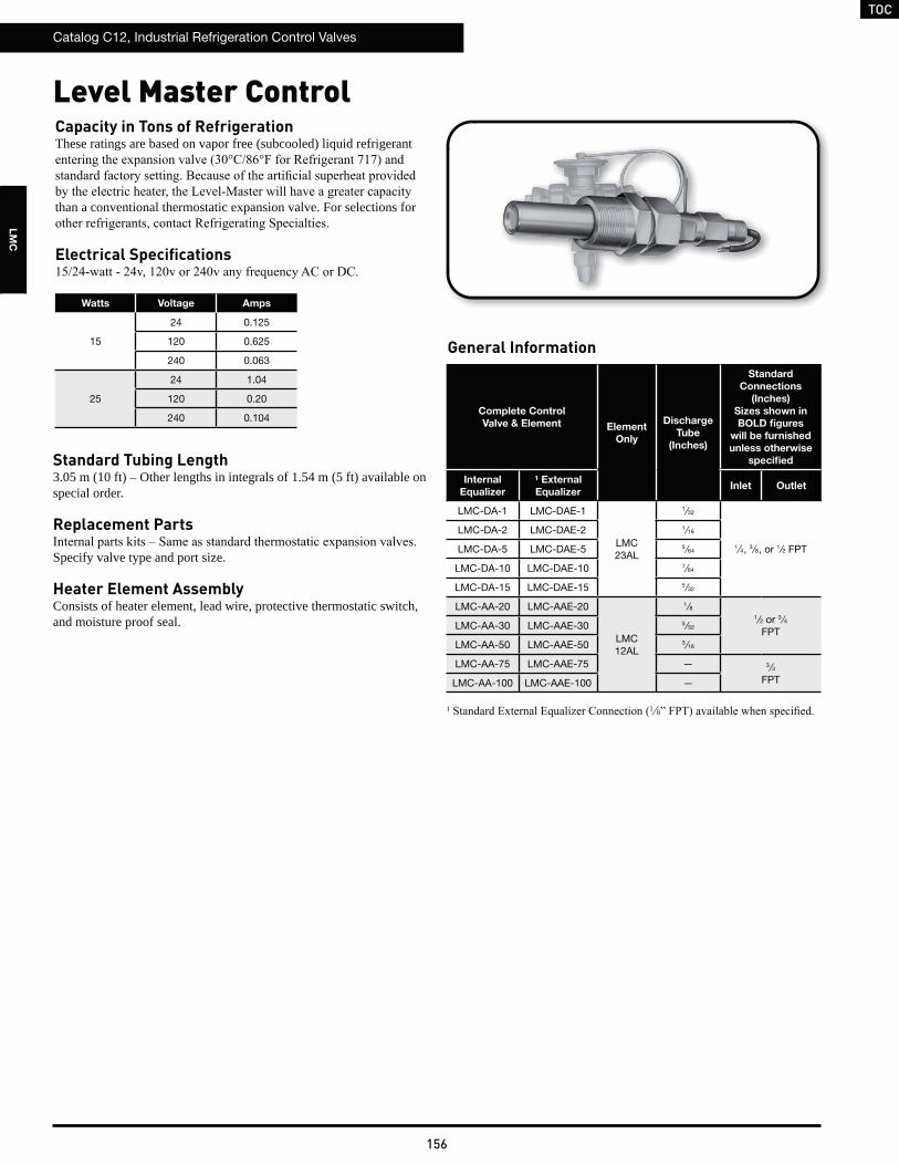
TOC
Catalog C12, Industrial Refrigeration Control Valves
156
LM
C
Capacity in Tons of RefrigerationThese ratings are based on vapor free (subcooled) liquid refrigerant
than a conventional thermostatic expansion valve. For selections for
Electrical Specifications
Complete Control
Valve & Element Element
Only
Discharge
Tube
(Inches)
Standard
Connections
(Inches)
Sizes shown in
BOLD figures
will be furnished
unless otherwise
specified
Internal
Equalizer
¹ External
Equalizer Inlet Outlet
LMC-DA-1 LMC-DAE-1
LMC 23AL
1⁄32
1 ⁄4, 3 ⁄8, or 1 ⁄2 FPT
LMC-DA-2 LMC-DAE-2 1⁄16
LMC-DA-5 LMC-DAE-5 5 ⁄64
LMC-DA-10 LMC-DAE-10 7⁄64
LMC-DA-15 LMC-DAE-15 5 ⁄32
LMC-AA-20 LMC-AAE-20
LMC 12AL
1⁄81 ⁄2 or 3 ⁄4
FPTLMC-AA-30 LMC-AAE-30 5 ⁄32
LMC-AA-50 LMC-AAE-50 3 ⁄16
LMC-AA-75 LMC-AAE-75 — 3⁄4 FPTLMC-AA-100 LMC-AAE-100 —
1 8
General Information
Level Master Control
Watts Voltage Amps
15
24 0.125
120 0.625
240 0.063
25
24 1.04
120 0.20
240 0.104
Standard Tubing Length3.05 m (10 ft) – Other lengths in integrals of 1.54 m (5 ft) available on special order.
Replacement Parts
Specify valve type and port size.
Heater Element AssemblyConsists of heater element, lead wire, protective thermostatic switch, and moisture proof seal.
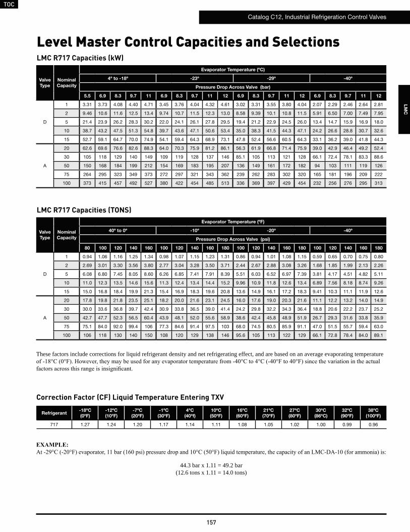
TOC
Catalog C12, Industrial Refrigeration Control Valves
157
LM
C
Valve
Type
Nominal
Capacity
Evaporator Temperature (ºF)
40º to 0º -10º -20º -40º
Pressure Drop Across Valve (psi)
80 100 120 140 160 100 120 140 160 180 100 120 140 160 180 100 120 140 160 180
D
1 0.94 1.06 1.16 1.25 1.34 0.98 1.07 1.15 1.23 1.31 0.86 0.94 1.01 1.08 1.15 0.59 0.65 0.70 0.75 0.80
2 2.69 3.01 3.30 3.56 3.80 2.77 3.04 3.28 3.50 3.71 2.44 2.67 2.88 3.08 3.26 1.68 1.85 1.99 2.13 2.26
5 6.08 6.80 7.45 8.05 8.60 6.26 6.85 7.41 7.91 8.39 5.51 6.03 6.52 6.97 7.39 3.81 4.17 4.51 4.82 5.11
10 11.0 12.3 13.5 14.6 15.6 11.3 12.4 13.4 14.4 15.2 9.96 10.9 11.8 12.6 13.4 6.89 7.56 8.18 8.74 9.26
15 15.0 16.8 18.4 19.9 21.3 15.4 16.9 18.3 19.6 20.8 13.6 14.9 16.1 17.2 18.3 9.41 10.3 11.1 11.9 12.6
A
20 17.8 19.8 21.8 23.5 25.1 18.2 20.0 21.6 23.1 24.5 16.0 17.6 19.0 20.3 21.6 11.1 12.2 13.2 14.0 14.9
30 30.0 33.6 36.8 39.7 42.4 30.9 33.8 36.5 39.0 41.4 24.2 29.8 32.2 34.3 36.4 18.8 20.6 22.2 23.7 25.2
50 42.7 47.7 52.3 56.5 60.4 43.9 48.1 52.0 55.6 58.9 38.6 42.4 45.8 48.9 51.9 26.7 29.3 31.6 33.8 35.9
75 75.1 84.0 92.0 99.4 106 77.3 84.6 91.4 97.5 103 68.0 74.5 80.5 85.9 91.1 47.0 51.5 55.7 59.4 63.0
100 106 118 130 140 150 108 120 129 138 146 95.6 105 113 122 129 66.1 72.8 78.4 84.0 89.1
These factors include corrections for liquid refrigerant density and net refrigerating effect, and are based on an average evaporating temperature
LMC R717 Capacities (TONS)
Level Master Control Capacities and Selections
Refrigerant-18ºC
(0ºF)
-12ºC
(10ºF)
-7ºC
(20ºF)
-1ºC
(30ºF)
4ºC
(40ºf)
10ºC
(50ºF)
16ºC
(60ºF)
21ºC
(70ºF)
27ºC
(80ºF)
30ºC
(86ºC)
32ºC
(90ºF)
38ºC
(100ºF)
717 1.27 1.24 1.20 1.17 1.14 1.11 1.08 1.05 1.02 1.00 0.99 0.96
Correction Factor (CF) Liquid Temperature Entering TXV
44.3 bar x 1.11 = 49.2 bar(12.6 tons x 1.11 = 14.0 tons)
Valve
Type
Nominal
Capacity
Evaporator Temperature (ºC)
4º to -18º -23º -29º -40º
Pressure Drop Across Valve (bar)
5.5 6.9 8.3 9.7 11 6.9 8.3 9.7 11 12 6.9 8.3 9.7 11 12 6.9 8.3 9.7 11 12
D
1 3.31 3.73 4.08 4.40 4.71 3.45 3.76 4.04 4.32 4.61 3.02 3.31 3.55 3.80 4.04 2.07 2.29 2.46 2.64 2.81
2 9.46 10.6 11.6 12.5 13.4 9.74 10.7 11.5 12.3 13.0 8.58 9.39 10.1 10.8 11.5 5.91 6.50 7.00 7.49 7.95
5 21.4 23.9 26.2 28.3 30.2 22.0 24.1 26.1 27.8 29.5 19.4 21.2 22.9 24.5 26.0 13.4 14.7 15.9 16.9 18.0
10 38.7 43.2 47.5 51.3 54.8 39.7 43.6 47.1 50.6 53.4 35.0 38.3 41.5 44.3 47.1 24.2 26.6 28.8 30.7 32.6
15 52.7 59.1 64.7 70.0 74.9 54.1 59.4 64.3 68.9 73.1 47.8 52.4 56.6 60.5 64.3 33.1 36.2 39.0 41.8 44.3
A
20 62.6 69.6 76.6 82.6 88.3 64.0 70.3 75.9 81.2 86.1 56.3 61.9 66.8 71.4 75.9 39.0 42.9 46.4 49.2 52.4
30 105 118 129 140 149 109 119 128 137 146 85.1 105 113 121 128 66.1 72.4 78.1 83.3 88.6
50 150 168 184 199 212 154 169 183 195 207 136 149 161 172 182 94 103 111 119 126
75 264 295 323 349 373 272 297 321 343 362 239 262 283 302 320 165 181 196 209 222
100 373 415 457 492 527 380 422 454 485 513 336 369 397 429 454 232 256 276 295 313
LMC R717 Capacities (kW)
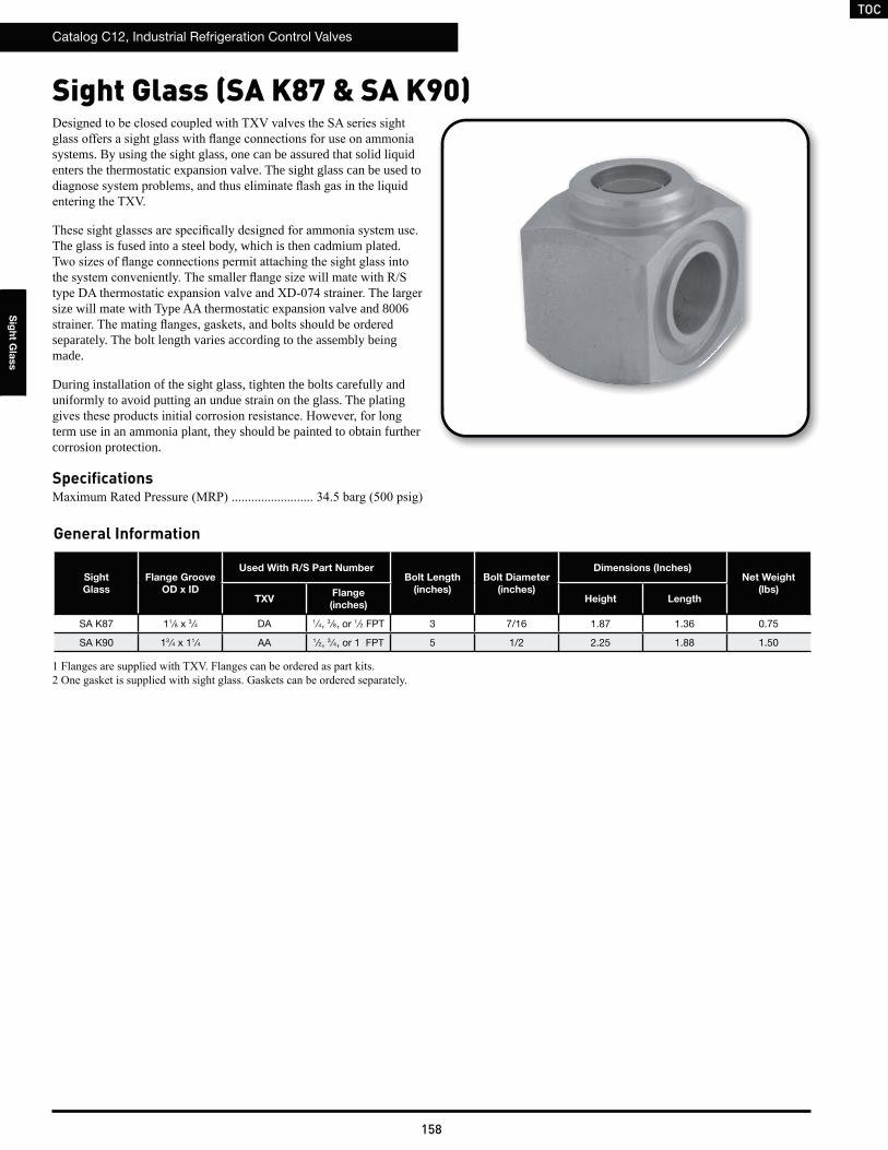
TOC
Catalog C12, Industrial Refrigeration Control Valves
158
Sig
ht G
lass
Sight Glass (SA K87 & SA K90)
systems. By using the sight glass, one can be assured that solid liquid enters the thermostatic expansion valve. The sight glass can be used to
The glass is fused into a steel body, which is then cadmium plated.
size will mate with Type AA thermostatic expansion valve and 8006
separately. The bolt length varies according to the assembly being made.
During installation of the sight glass, tighten the bolts carefully and uniformly to avoid putting an undue strain on the glass. The plating
term use in an ammonia plant, they should be painted to obtain further corrosion protection.
Specifications
General Information
Sight
Glass
Flange Groove
OD x ID
Used With R/S Part NumberBolt Length
(inches)
Bolt Diameter
(inches)
Dimensions (Inches)Net Weight
(lbs)TXV
Flange
(inches)Height Length
SA K87 11⁄8 x 3 ⁄4 DA 1⁄4, 3 ⁄8, or 1 ⁄2 FPT 3 7/16 1.87 1.36 0.75
SA K90 13 ⁄4 x 11⁄4 AA 1⁄2, 3 ⁄4, or 1 FPT 5 1/2 2.25 1.88 1.50
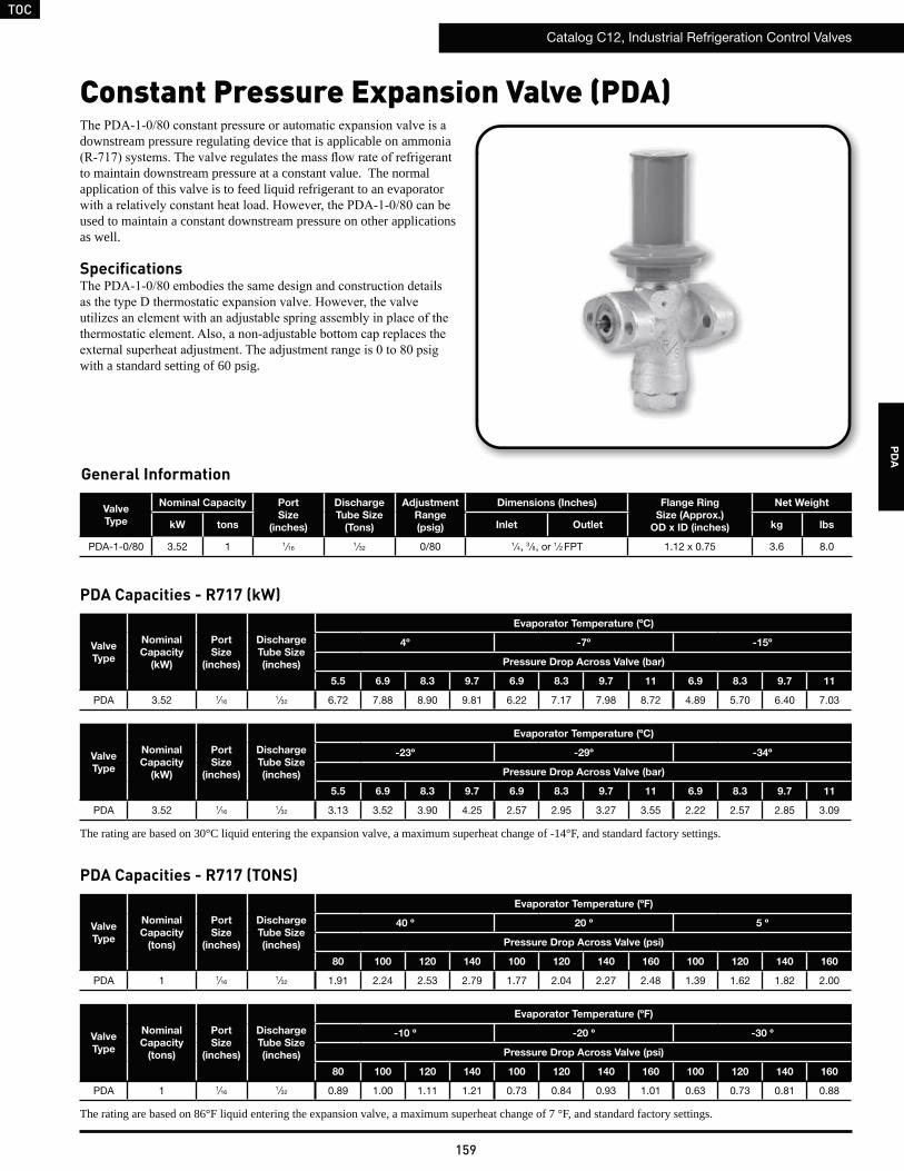
TOC
Catalog C12, Industrial Refrigeration Control Valves
159
PD
A
Constant Pressure Expansion Valve (PDA)
Valve
Type
Nominal Capacity Port
Size
(inches)
Discharge
Tube Size
(Tons)
Adjustment
Range
(psig)
Dimensions (Inches) Flange Ring
Size (Approx.)
OD x ID (inches)
Net Weight
kW tons Inlet Outlet kg lbs
PDA-1-0/80 3.52 1 1⁄161 ⁄32 0/80 1⁄4, 3 ⁄8, or 1 ⁄2 FPT 1.12 x 0.75 3.6 8.0
downstream pressure regulating device that is applicable on ammonia
to maintain downstream pressure at a constant value. The normal application of this valve is to feed liquid refrigerant to an evaporator
used to maintain a constant downstream pressure on other applications as well.
Specifications
with a standard setting of 60 psig.
Valve
Type
Nominal
Capacity
(tons)
Port
Size
(inches)
Discharge
Tube Size
(inches)
Evaporator Temperature (ºF)
40 º 20 º 5 º
Pressure Drop Across Valve (psi)
80 100 120 140 100 120 140 160 100 120 140 160
PDA 1 1⁄161 ⁄32 1.91 2.24 2.53 2.79 1.77 2.04 2.27 2.48 1.39 1.62 1.82 2.00
Valve
Type
Nominal
Capacity
(tons)
Port
Size
(inches)
Discharge
Tube Size
(inches)
Evaporator Temperature (ºF)
-10 º -20 º -30 º
Pressure Drop Across Valve (psi)
80 100 120 140 100 120 140 160 100 120 140 160
PDA 1 1⁄161 ⁄32 0.89 1.00 1.11 1.21 0.73 0.84 0.93 1.01 0.63 0.73 0.81 0.88
The rating are based on 86°F liquid entering the expansion valve, a maximum superheat change of 7 °F, and standard factory settings.
General Information
PDA Capacities - R717 (TONS)
Valve
Type
Nominal
Capacity
(kW)
Port
Size
(inches)
Discharge
Tube Size
(inches)
Evaporator Temperature (ºC)
4º -7º -15º
Pressure Drop Across Valve (bar)
5.5 6.9 8.3 9.7 6.9 8.3 9.7 11 6.9 8.3 9.7 11
PDA 3.52 1⁄161 ⁄32 6.72 7.88 8.90 9.81 6.22 7.17 7.98 8.72 4.89 5.70 6.40 7.03
Valve
Type
Nominal
Capacity
(kW)
Port
Size
(inches)
Discharge
Tube Size
(inches)
Evaporator Temperature (ºC)
-23º -29º -34º
Pressure Drop Across Valve (bar)
5.5 6.9 8.3 9.7 6.9 8.3 9.7 11 6.9 8.3 9.7 11
PDA 3.52 1⁄161 ⁄32 3.13 3.52 3.90 4.25 2.57 2.95 3.27 3.55 2.22 2.57 2.85 3.09
The rating are based on 30°C liquid entering the expansion valve, a maximum superheat change of -14°F, and standard factory settings.
PDA Capacities - R717 (kW)
TOC
Catalog C12, Industrial Refrigeration Control Valves
160
Schematic Flow Diagrams
AA P P E N D I X
A4 Schematic Flow Diagrams 161
Dual Position Valves Schematic Flow Diagrams 165
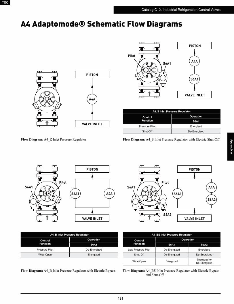
TOC
Catalog C12, Industrial Refrigeration Control Valves
161
Ap
pe
nd
ix A
A4 Adaptomode® Schematic Flow Diagrams
VALVE INLET
PISTON
A4AS6A1
S6A1Pilot
VALVE INLET
PISTON
A4AVALVE INLET
PISTON
A4A
S6A1
S6A1
Pilot
VALVE INLET
PISTON
A4A
S6A1
S6A1Pilot
S6A2
S6A2
and Shut-Off
A4_BS Inlet Pressure Regulator
Control
Function
Operation
S6A1 S6A2
Low Pressure Pilot De-Energized Energized
Shut-Off De-Energized De-Energized
Wide Open Energized Energized orDe-Energized
A4_S Inlet Pressure Regulator
Control
Function
Operation
S6A1
Pressure Pilot Energized
Shut-Off De-Energized
A4_B Inlet Pressure Regulator
Control
Function
Operation
S6A1
Pressure Pilot De-Energized
Wide Open Energized
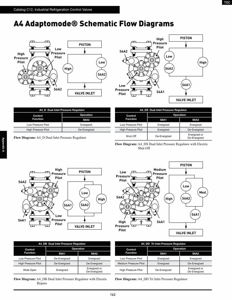
TOC
Catalog C12, Industrial Refrigeration Control Valves
162
Ap
pe
nd
ix A
VALVE INLET
PISTON
Low
High
LowPressure
Pilot
S6A2
S6A2
HighPressure
Pilot
A4 Adaptomode® Schematic Flow Diagrams
A4_DB Dual Inlet Pressure Regulator
Control
Function
Operation
S6A1 S6A2
Low Pressure Pilot De-Energized Energized
High Pressure Pilot De-Energized De-Energized
Wide Open Energized Energized orDe-Energized
Bypass
VALVE INLET
PISTON
Low
High
LowPressure
Pilot
S6A2
S6A2
HighPressure
Pilot
S6A1
S6A1
A4_D Dual Inlet Pressure Regulator
Control
Function
Operation
S6A2
Low Pressure Pilot Energized
High Pressure Pilot De-Energized
VALVE INLET
PISTON
Low
High
LowPressure
Pilot
S6A2
S6A2
HighPressure
Pilot
S6A1
S6A1
A4_DS Dual Inlet Pressure Regulator
Control
Function
Operation
S6A1 S6A2
Low Pressure Pilot Energized Energized
High Pressure Pilot Energized De-Energized
Shut-Off De-EnergizedEnergized orDe-Energized
Shut-Off
VALVE INLET
PISTON
Low
High
LowPressure
Pilot
S6A2S6A2
MediumPressure
Pilot
S6A1
S6A1
A4_DD Tri Inlet Pressure Regulator
Control
Function
Operation
S6A1 S6A2
Low Pressure Pilot Energized Energized
Medium Pressure Pilot Energized De-Energized
High Pressure Pilot De-Energized Energized orDe-Energized
Med.
HighPressure
Pilot
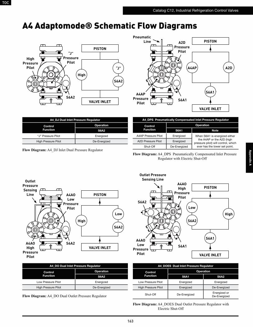
TOC
Catalog C12, Industrial Refrigeration Control Valves
163
Ap
pe
nd
ix A
VALVE INLET
PISTON
“J”
High
“J”Pressure
Pilot
S6A2
S6A2
HighPressure
Pilot
A4 Adaptomode® Schematic Flow Diagrams
A4_DJ Dual Inlet Pressure Regulator
Control
Function
Operation
S6A2
“J” Pressure Pilot Energized
High Pressure Pilot De-Energized
VALVE INLET
PISTON
Low
High
A4AOLow
PressurePilot
S6A2
S6A2A4AOHigh
PressurePilot
A4_DO Dual Inlet Pressure Regulator
Control
Function
Operation
S6A2
Low Pressure Pilot Energized
High Pressure Pilot De-Energized
VALVE INLET
PISTON
Low
High
A4AOLow
PressurePilot
S6A2
S6A2
A4AOHigh
PressurePilot
S6A1
S6A1
A4_DOES Dual Inlet Pressure Regulator
Control
Function
Operation
S6A1 S6A2
Low Pressure Pilot Energized Energized
High Pressure Pilot Energized De-Energized
Shut-Off De-EnergizedEnergized orDe-Energized
Outlet PressureSensing LineOutlet
PressureSensing
Line
VALVE INLET
PISTON
A4AP A2D
A4APPressure
Pilot
A2DPressure
Pilot
S6A1
S6A1
A4_DPS Pneumatically Compensated Inlet Pressure Regulator
Control
Function
Operation
S6A1 Note
A4AP Pressure Pilot Energized When S6A1 is energized either the A4AP or the A2D (high
pressure pilot) will control, which ever has the lower set point.
A2D Pressure Pilot Energized
Shut-Off De-Energized
PneumaticLine
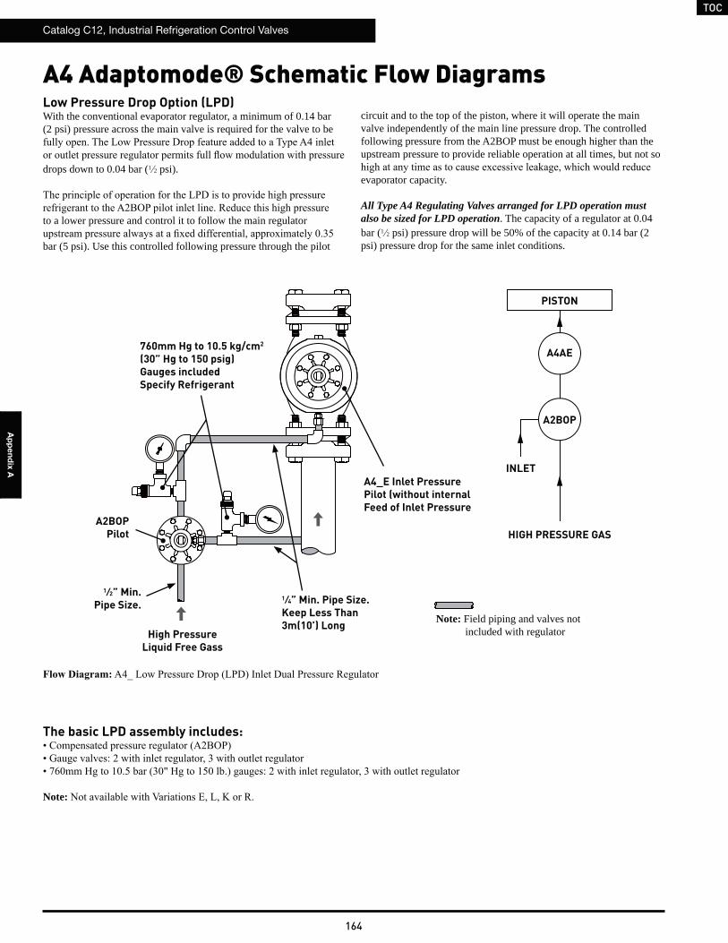
TOC
Catalog C12, Industrial Refrigeration Control Valves
164
Ap
pe
nd
ix A
A4 Adaptomode® Schematic Flow Diagrams
HIGH PRESSURE GAS
PISTON
A2BOP Pilot
A4AE
A4_E Inlet Pressure Pilot (without internal Feed of Inlet Pressure
A2BOP
High Pressure Liquid Free Gass
INLET
1⁄4” Min. Pipe Size.Keep Less Than 3m(10’) Long
1⁄2” Min. Pipe Size.
760mm Hg to 10.5 kg/cm2
(30” Hg to 150 psig)Gauges includedSpecify Refrigerant
Note: Field piping and valves not included with regulator
Low Pressure Drop Option (LPD)With the conventional evaporator regulator, a minimum of 0.14 bar (2 psi) pressure across the main valve is required for the valve to be
drops down to 0.04 bar (1 2 psi).
to a lower pressure and control it to follow the main regulator
bar (5 psi). Use this controlled following pressure through the pilot
circuit and to the top of the piston, where it will operate the main valve independently of the main line pressure drop. The controlled following pressure from the A2BOP must be enough higher than the upstream pressure to provide reliable operation at all times, but not so
evaporator capacity.
All Type A4 Regulating Valves arranged for LPD operation must also be sized for LPD operation. The capacity of a regulator at 0.04 bar (1 2 psi) pressure drop will be 50% of the capacity at 0.14 bar (2 psi) pressure drop for the same inlet conditions.
The basic LPD assembly includes:
Note:
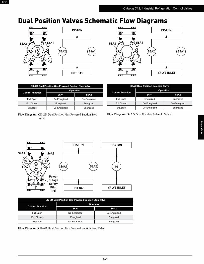
TOC
Catalog C12, Industrial Refrigeration Control Valves
165
Ap
pe
nd
ix A
Dual Position Valves Schematic Flow Diagrams
CK-6D Dual Position Gas Powered Suction Stop Valve
Control FunctionOperation
S6A1 S6A2
Full Open De-Energized De-Energized
Full Closed Energized Energized
Equalize De-Energized Energized
PISTON
P1
Power Outage Safety Pilot(P1)
S6A2
S6A2
S6A1
S6A1
HOT GAS VALVE INLET
PISTON
S6A2 S6A1
S6A2 S6A1
PISTON
HOT GAS
CK-2D Dual Position Gas Powered Suction Stop Valve
Control FunctionOperation
S6A1 S6A2
Full Open De-Energized De-Energized
Full Closed Energized Energized
Equalize De-Energized Energized
Valve
S6A2 S6A1
S6A2 S6A1
PISTON
S4AD Dual Position Solenoid Valve
Control FunctionOperation
S6A1 S6A2
Full Open Energized Energized
Full Closed De-Energized De-Energized
Equalize De-Energized Energized
S4AD Dual Position Solenoid Valve
VALVE INLET
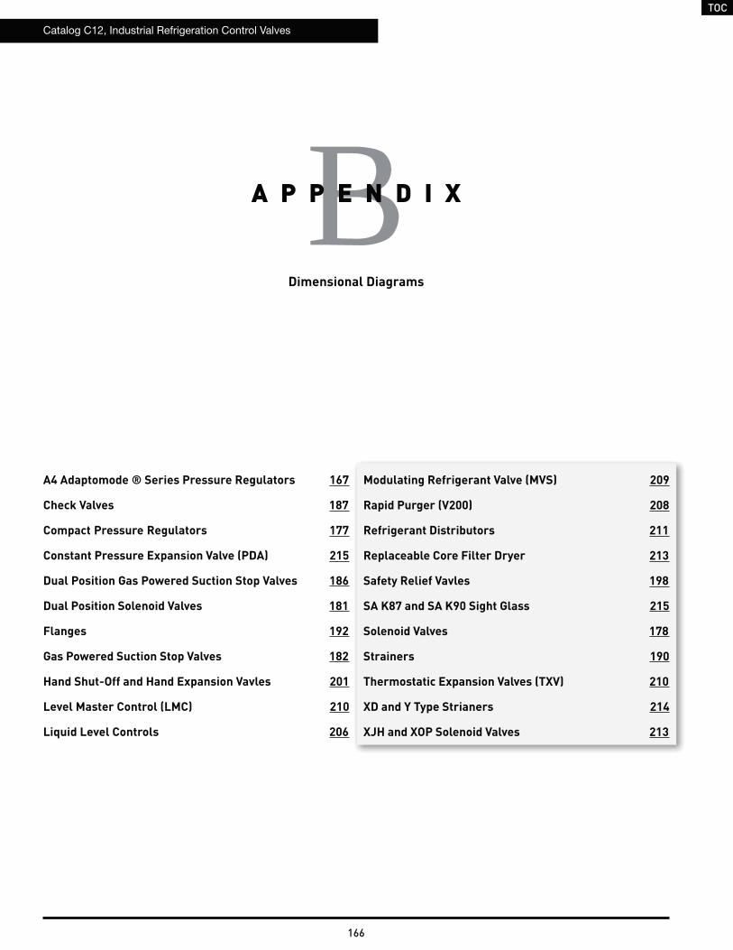
TOC
Catalog C12, Industrial Refrigeration Control Valves
166
Dimensional Diagrams
BA P P E N D I X
A4 Adaptomode ® Series Pressure Regulators 167
Check Valves 187
Compact Pressure Regulators 177
Constant Pressure Expansion Valve (PDA) 215
Dual Position Gas Powered Suction Stop Valves 186
Dual Position Solenoid Valves 181
Flanges 192
Gas Powered Suction Stop Valves 182
Hand Shut-Off and Hand Expansion Vavles 201
Level Master Control (LMC) 210
Liquid Level Controls 206
Modulating Refrigerant Valve (MVS) 209
Rapid Purger (V200) 208
Refrigerant Distributors 211
Replaceable Core Filter Dryer 213
Safety Relief Vavles 198
SA K87 and SA K90 Sight Glass 215
Solenoid Valves 178
Strainers 190
Thermostatic Expansion Valves (TXV) 210
XD and Y Type Strianers 214
XJH and XOP Solenoid Valves 213
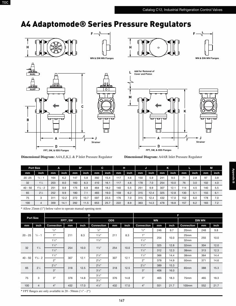
TOC
Catalog C12, Industrial Refrigeration Control Valves
167
Ap
pe
nd
ix B
H
B
A
C
F
J
FPT, SW, & ODS Flanges
WN & DIN WN Flanges
D
Port Size A B* C H J K L M
mm inch mm inch mm inch mm inch mm inch mm inch mm inch mm inch mm inch
20 -25 3 ⁄4 - 1 164 6.2 147 5.8 392 15.4 117 4.6 150 5.9 241 9.5 71 2.8 97 3.8
32 11⁄4 203 8.0 160 6.3 410 16.1 117 4.6 178 7.0 254 10.0 76 3.0 102 4.0
40 - 50 15 ⁄8 - 2 251 9.9 175 6.9 464 18.2 140 5.5 251 9.9 307 12.1 114 4.5 140 5.5
65 21⁄2 252 9.9 180 7.1 483 19.0 159 6.2 315 12.4 325 12.8 130 5.1 155 6.1
75 3 311 12.2 272 10.7 597 23.5 176 7.0 315 12.4 432 17.0 152 6.0 178 7.0
100 4 359 14.1 292 11.5 653 25.7 222 8.9 363 14.3 478 18.8 157 6.2 183 7.2
Strainer
3 4” - 2”)
* Allow 25mm (1”) below valve to operate manual opening stem
A
FPT, SW, & ODS FlangesD
K
M
L
JStrainer
H
F
A4 Adaptomode® Series Pressure Regulators
WN & DIN WN Flanges
Port SizeD F
FPT*, SW ODS WN DIN WN
mm inch Connection mm inch Connection mm inch Connection mm inch Connection mm inch
20 - 25 3 ⁄4 - 1
3 ⁄4”
211 8.3
7⁄8”
211 8.3
3 ⁄4” 246 9.7 20mm 248 9.8
1” 11⁄8” 1”254 10.0
25mm255 10.0
11⁄4” 13 ⁄8” 11⁄4” 32mm
32 11⁄411⁄4”
254 10.0 15 ⁄8” 254 10.011⁄4” 325 12.8 32mm 304 12.0
11⁄2” 11⁄2” 312 12.3 38mm 313 12.3
40 - 50 15 ⁄8 - 211⁄2”
307 12.121⁄8”
307 12.111⁄2” 366 14.4 38mm 364 14.4
2” 25 ⁄8” 2” 378 14.9 50mm 371 14.6
65 21⁄221⁄2”
318 12.525 ⁄8”
318 12.521⁄2” 389 15.3
65mm 388 15.33” 31⁄8” 3” 406 16.0
75 3 3” 376 14.831⁄8”
376 14.8 3” 465 18.3 75mm 465 18.335 ⁄8”
100 4 4” 432 17.0 41⁄8” 432 17.0 4” 551 21.7 100mm 552 21.7
A4AP
A4ALAdd for Removal ofCover and Piston
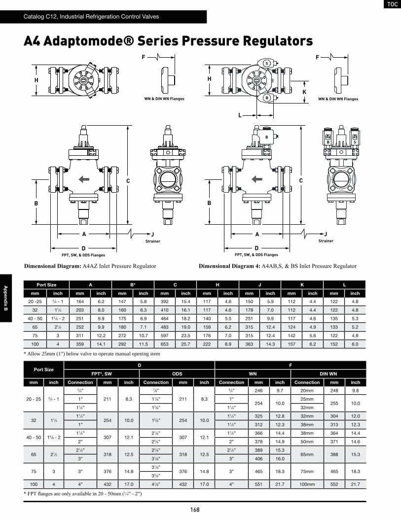
TOC
Catalog C12, Industrial Refrigeration Control Valves
168
Ap
pe
nd
ix B
H
F
WN & DIN WN Flanges
3 4” - 2”)
Port Size A B* C H J K L
mm inch mm inch mm inch mm inch mm inch mm inch mm inch mm inch
20 -25 3 ⁄4 - 1 164 6.2 147 5.8 392 15.4 117 4.6 150 5.9 112 4.4 122 4.8
32 11⁄4 203 8.0 160 6.3 410 16.1 117 4.6 178 7.0 112 4.4 122 4.8
40 - 50 15 ⁄8 - 2 251 9.9 175 6.9 464 18.2 140 5.5 251 9.9 117 4.6 135 5.3
65 21⁄2 252 9.9 180 7.1 483 19.0 159 6.2 315 12.4 124 4.9 133 5.2
75 3 311 12.2 272 10.7 597 23.5 176 7.0 315 12.4 142 5.6 122 4.8
100 4 359 14.1 292 11.5 653 25.7 222 8.9 363 14.3 157 6.2 152 6.0
* Allow 25mm (1”) below valve to operate manual opening stem
A4 Adaptomode® Series Pressure Regulators
Port SizeD F
FPT*, SW ODS WN DIN WN
mm inch Connection mm inch Connection mm inch Connection mm inch Connection mm inch
20 - 25 3 ⁄4 - 1
3 ⁄4”
211 8.3
7⁄8”
211 8.3
3 ⁄4” 246 9.7 20mm 248 9.8
1” 11⁄8” 1”254 10.0
25mm255 10.0
11⁄4” 13 ⁄8” 11⁄4” 32mm
32 11⁄411⁄4”
254 10.0 15 ⁄8” 254 10.011⁄4” 325 12.8 32mm 304 12.0
1” 11⁄2” 312 12.3 38mm 313 12.3
40 - 50 15 ⁄8 - 211⁄2”
307 12.121⁄8”
307 12.111⁄2” 366 14.4 38mm 364 14.4
2” 25 ⁄8” 2” 378 14.9 50mm 371 14.6
65 21⁄221⁄2”
318 12.525 ⁄8”
318 12.521⁄2” 389 15.3
65mm 388 15.33” 31⁄8” 3” 406 16.0
75 3 3” 376 14.831⁄8”
376 14.8 3” 465 18.3 75mm 465 18.335 ⁄8”
100 4 4” 432 17.0 41⁄8” 432 17.0 4” 551 21.7 100mm 552 21.7
F
WN & DIN WN Flanges
H
K
L
S
B
B
A
C
J
DStrainer
FPT, SW, & ODS Flanges
B
A
C
J
DStrainer
FPT, SW, & ODS Flanges
BB S
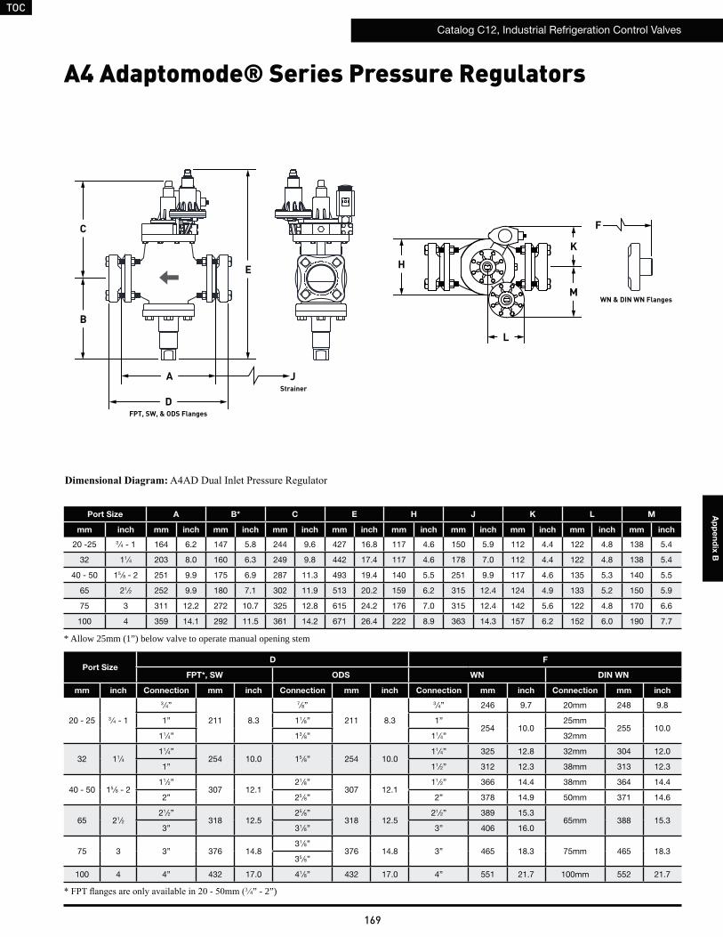
TOC
Catalog C12, Industrial Refrigeration Control Valves
169
Ap
pe
nd
ix B
3 4” - 2”)
Port Size A B* C E H J K L M
mm inch mm inch mm inch mm inch mm inch mm inch mm inch mm inch mm inch mm inch
20 -25 3 ⁄4 - 1 164 6.2 147 5.8 244 9.6 427 16.8 117 4.6 150 5.9 112 4.4 122 4.8 138 5.4
32 11⁄4 203 8.0 160 6.3 249 9.8 442 17.4 117 4.6 178 7.0 112 4.4 122 4.8 138 5.4
40 - 50 15 ⁄8 - 2 251 9.9 175 6.9 287 11.3 493 19.4 140 5.5 251 9.9 117 4.6 135 5.3 140 5.5
65 21⁄2 252 9.9 180 7.1 302 11.9 513 20.2 159 6.2 315 12.4 124 4.9 133 5.2 150 5.9
75 3 311 12.2 272 10.7 325 12.8 615 24.2 176 7.0 315 12.4 142 5.6 122 4.8 170 6.6
100 4 359 14.1 292 11.5 361 14.2 671 26.4 222 8.9 363 14.3 157 6.2 152 6.0 190 7.7
* Allow 25mm (1”) below valve to operate manual opening stem
A4 Adaptomode® Series Pressure Regulators
Port SizeD F
FPT*, SW ODS WN DIN WN
mm inch Connection mm inch Connection mm inch Connection mm inch Connection mm inch
20 - 25 3 ⁄4 - 1
3 ⁄4”
211 8.3
7⁄8”
211 8.3
3 ⁄4” 246 9.7 20mm 248 9.8
1” 11⁄8” 1”254 10.0
25mm255 10.0
11⁄4” 13 ⁄8” 11⁄4” 32mm
32 11⁄411⁄4”
254 10.0 15 ⁄8” 254 10.011⁄4” 325 12.8 32mm 304 12.0
1” 11⁄2” 312 12.3 38mm 313 12.3
40 - 50 15 ⁄8 - 211⁄2”
307 12.121⁄8”
307 12.111⁄2” 366 14.4 38mm 364 14.4
2” 25 ⁄8” 2” 378 14.9 50mm 371 14.6
65 21⁄221⁄2”
318 12.525 ⁄8”
318 12.521⁄2” 389 15.3
65mm 388 15.33” 31⁄8” 3” 406 16.0
75 3 3” 376 14.831⁄8”
376 14.8 3” 465 18.3 75mm 465 18.335 ⁄8”
100 4 4” 432 17.0 41⁄8” 432 17.0 4” 551 21.7 100mm 552 21.7
F
WN & DIN WN Flanges
B
A
C
J
FPT, SW, & ODS FlangesD
Strainer
E H
K
M
L
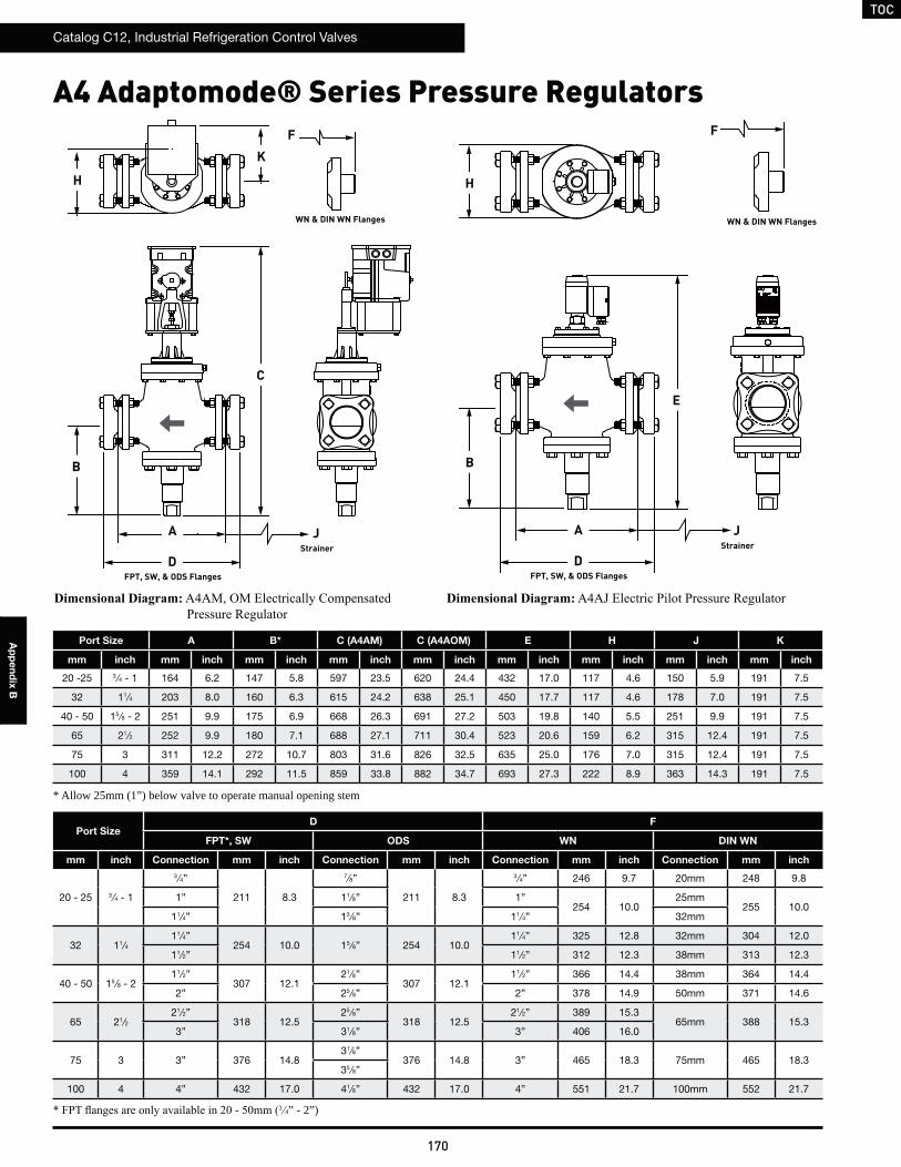
TOC
Catalog C12, Industrial Refrigeration Control Valves
170
Ap
pe
nd
ix B
A4 Adaptomode® Series Pressure Regulators
Port Size A B* C (A4AM) C (A4AOM) E H J K
mm inch mm inch mm inch mm inch mm inch mm inch mm inch mm inch mm inch
20 -25 3 ⁄4 - 1 164 6.2 147 5.8 597 23.5 620 24.4 432 17.0 117 4.6 150 5.9 191 7.5
32 11⁄4 203 8.0 160 6.3 615 24.2 638 25.1 450 17.7 117 4.6 178 7.0 191 7.5
40 - 50 15 ⁄8 - 2 251 9.9 175 6.9 668 26.3 691 27.2 503 19.8 140 5.5 251 9.9 191 7.5
65 21⁄2 252 9.9 180 7.1 688 27.1 711 30.4 523 20.6 159 6.2 315 12.4 191 7.5
75 3 311 12.2 272 10.7 803 31.6 826 32.5 635 25.0 176 7.0 315 12.4 191 7.5
100 4 359 14.1 292 11.5 859 33.8 882 34.7 693 27.3 222 8.9 363 14.3 191 7.5
3 4” - 2”)
Port SizeD F
FPT*, SW ODS WN DIN WN
mm inch Connection mm inch Connection mm inch Connection mm inch Connection mm inch
20 - 25 3 ⁄4 - 1
3 ⁄4”
211 8.3
7⁄8”
211 8.3
3 ⁄4” 246 9.7 20mm 248 9.8
1” 11⁄8” 1”254 10.0
25mm255 10.0
11⁄4” 13 ⁄8” 11⁄4” 32mm
32 11⁄411⁄4”
254 10.0 15 ⁄8” 254 10.011⁄4” 325 12.8 32mm 304 12.0
11⁄2” 11⁄2” 312 12.3 38mm 313 12.3
40 - 50 15 ⁄8 - 211⁄2”
307 12.121⁄8”
307 12.111⁄2” 366 14.4 38mm 364 14.4
2” 25 ⁄8” 2” 378 14.9 50mm 371 14.6
65 21⁄221⁄2”
318 12.525 ⁄8”
318 12.521⁄2” 389 15.3
65mm 388 15.33” 31⁄8” 3” 406 16.0
75 3 3” 376 14.831⁄8”
376 14.8 3” 465 18.3 75mm 465 18.335 ⁄8”
100 4 4” 432 17.0 41⁄8” 432 17.0 4” 551 21.7 100mm 552 21.7
* Allow 25mm (1”) below valve to operate manual opening stem
A J
FPT, SW, & ODS FlangesD
Strainer
B
C
WN & DIN WN Flanges
K
F
H
A J
FPT, SW, & ODS FlangesD
Strainer
B
WN & DIN WN Flanges
F
H
E
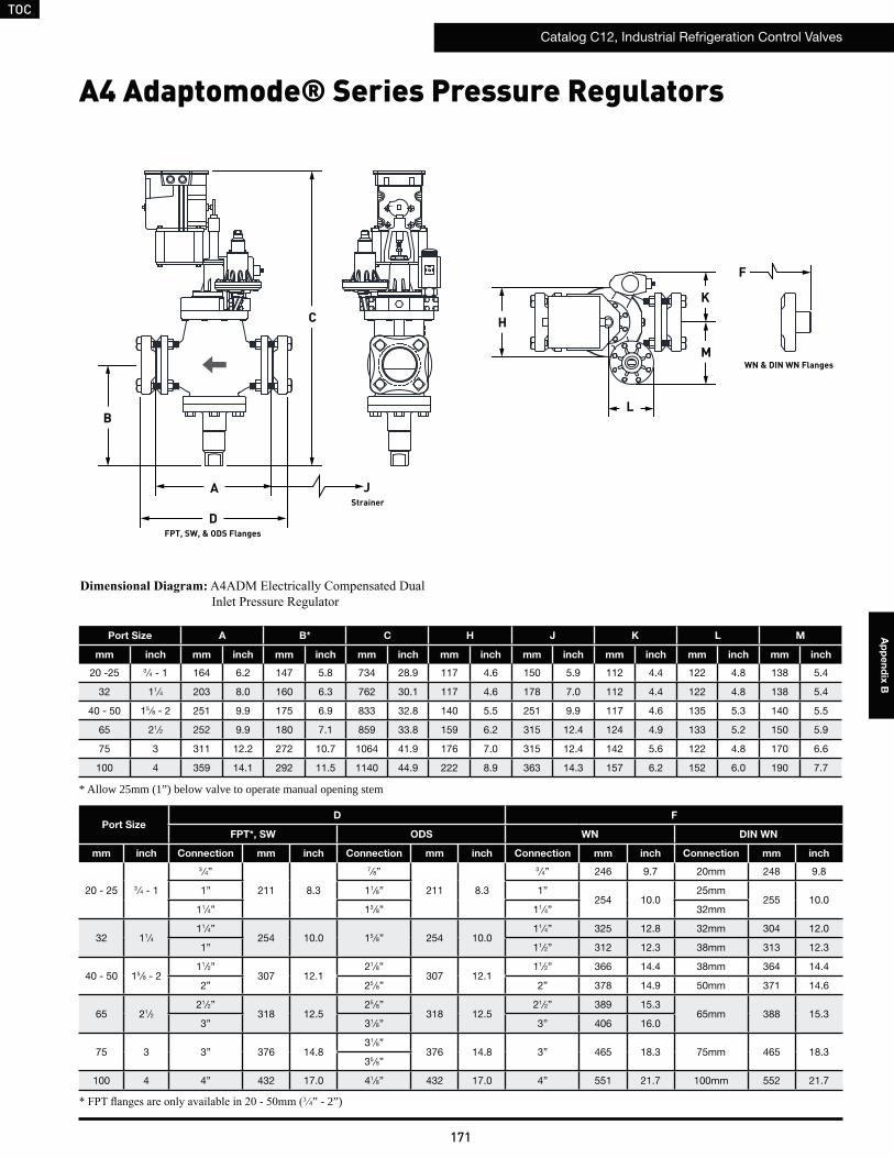
TOC
Catalog C12, Industrial Refrigeration Control Valves
171
Ap
pe
nd
ix B
3 4” - 2”)
Port Size A B* C H J K L M
mm inch mm inch mm inch mm inch mm inch mm inch mm inch mm inch mm inch
20 -25 3 ⁄4 - 1 164 6.2 147 5.8 734 28.9 117 4.6 150 5.9 112 4.4 122 4.8 138 5.4
32 11⁄4 203 8.0 160 6.3 762 30.1 117 4.6 178 7.0 112 4.4 122 4.8 138 5.4
40 - 50 15 ⁄8 - 2 251 9.9 175 6.9 833 32.8 140 5.5 251 9.9 117 4.6 135 5.3 140 5.5
65 21⁄2 252 9.9 180 7.1 859 33.8 159 6.2 315 12.4 124 4.9 133 5.2 150 5.9
75 3 311 12.2 272 10.7 1064 41.9 176 7.0 315 12.4 142 5.6 122 4.8 170 6.6
100 4 359 14.1 292 11.5 1140 44.9 222 8.9 363 14.3 157 6.2 152 6.0 190 7.7
* Allow 25mm (1”) below valve to operate manual opening stem
A4 Adaptomode® Series Pressure Regulators
Port SizeD F
FPT*, SW ODS WN DIN WN
mm inch Connection mm inch Connection mm inch Connection mm inch Connection mm inch
20 - 25 3 ⁄4 - 1
3 ⁄4”
211 8.3
7⁄8”
211 8.3
3 ⁄4” 246 9.7 20mm 248 9.8
1” 11⁄8” 1”254 10.0
25mm255 10.0
11⁄4” 13 ⁄8” 11⁄4” 32mm
32 11⁄411⁄4”
254 10.0 15 ⁄8” 254 10.011⁄4” 325 12.8 32mm 304 12.0
1” 11⁄2” 312 12.3 38mm 313 12.3
40 - 50 15 ⁄8 - 211⁄2”
307 12.121⁄8”
307 12.111⁄2” 366 14.4 38mm 364 14.4
2” 25 ⁄8” 2” 378 14.9 50mm 371 14.6
65 21⁄221⁄2”
318 12.525 ⁄8”
318 12.521⁄2” 389 15.3
65mm 388 15.33” 31⁄8” 3” 406 16.0
75 3 3” 376 14.831⁄8”
376 14.8 3” 465 18.3 75mm 465 18.335 ⁄8”
100 4 4” 432 17.0 41⁄8” 432 17.0 4” 551 21.7 100mm 552 21.7
B
A
C
J
FPT, SW, & ODS FlangesD
Strainer
H
K
M
L
F
WN & DIN WN Flanges
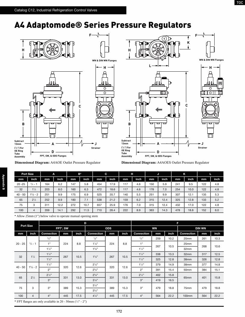
TOC
Catalog C12, Industrial Refrigeration Control Valves
172
Ap
pe
nd
ix B
H
B
A
C
H
F
J
FPT, SW, & ODS Flanges
WN & DIN WN Flanges
DStrainer
A4 Adaptomode® Series Pressure Regulators
Subtract 13mm
(1 ⁄2”) For OE Ring Tube Assembly
Port Size A B* C H J K L
mm inch mm inch mm inch mm inch mm inch mm inch mm inch mm inch
20 -25 3 ⁄4 - 1 164 6.2 147 5.8 454 17.9 117 4.6 150 5.9 241 9.5 122 4.8
32 11⁄4 203 8.0 160 6.3 472 18.6 117 4.6 178 7.0 254 10.0 122 4.8
40 - 50 15 ⁄8 - 2 251 9.9 175 6.9 525 20.7 140 5.5 251 9.9 307 12.1 135 5.3
65 21⁄2 252 9.9 180 7.1 538 21.2 159 6.2 315 12.4 325 12.8 133 5.2
75 3 311 12.2 272 10.7 657 25.9 176 7.0 315 12.4 432 17.0 122 4.8
100 4 359 14.1 292 11.5 710 28.4 222 8.9 363 14.3 478 18.8 152 6.0
3 4” - 2”)
Port SizeD F
FPT*, SW ODS WN DIN WN
mm inch Connection mm inch Connection mm inch Connection mm inch Connection mm inch
20 - 25 3 ⁄4 - 1
3 ⁄4”
224 8.8
7⁄8”
224 8.8
3 ⁄4” 259 10.2 20mm 261 10.3
1” 11⁄8” 1”267 10.5
25mm268 10.6
11⁄4” 13 ⁄8” 11⁄4” 32mm
32 11⁄411⁄4”
267 10.5 15 ⁄8” 267 10.511⁄4” 338 13.3 32mm 317 12.5
11⁄2” 11⁄2” 325 12.8 38mm 326 12.8
40 - 50 15 ⁄8 - 211⁄2”
320 12.621⁄8”
320 12.611⁄2” 379 14.9 38mm 377 14.8
2” 25 ⁄8” 2” 391 15.4 50mm 384 15.1
65 21⁄221⁄2”
331 13.025 ⁄8”
331 13.021⁄2” 402 15.8
65mm 401 15.83” 31⁄8” 3” 419 16.5
75 3 3” 389 15.331⁄8”
389 15.3 3” 479 18.8 75mm 479 18.835 ⁄8”
100 4 4” 445 17.5 41⁄8” 445 17.5 4” 564 22.2 100mm 564 22.2
* Allow 25mm (1”) below valve to operate manual opening stem
K
Subtract 13mm
(1 ⁄2”) For OE Ring Tube Assembly
B
A J
FPT, SW, & ODS FlangesD
Strainer
C
H
H
F
WN & DIN WN Flanges
S
L
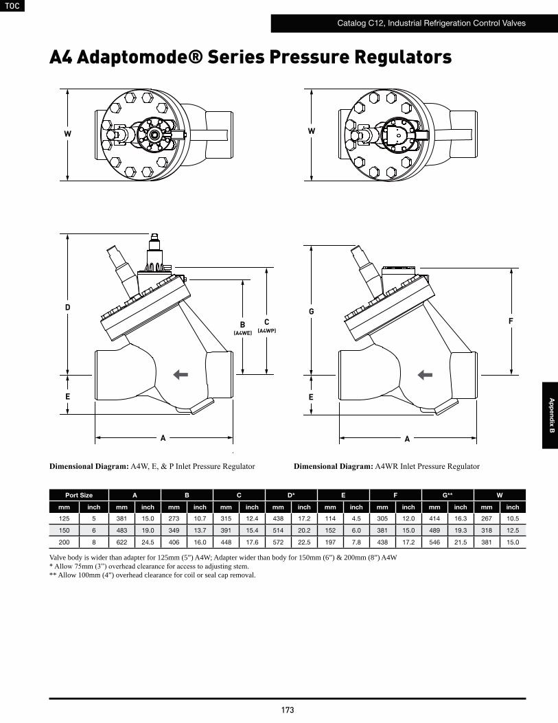
TOC
Catalog C12, Industrial Refrigeration Control Valves
173
Ap
pe
nd
ix B
A4 Adaptomode® Series Pressure Regulators
CB(A4WP)
W
(A4WE)
W
G
E
A
F
Port Size A B C D* E F G** W
mm inch mm inch mm inch mm inch mm inch mm inch mm inch mm inch mm inch
125 5 381 15.0 273 10.7 315 12.4 438 17.2 114 4.5 305 12.0 414 16.3 267 10.5
150 6 483 19.0 349 13.7 391 15.4 514 20.2 152 6.0 381 15.0 489 19.3 318 12.5
200 8 622 24.5 406 16.0 448 17.6 572 22.5 197 7.8 438 17.2 546 21.5 381 15.0
Valve body is wider than adapter for 125mm (5”) A4W; Adapter wider than body for 150mm (6”) & 200mm (8”) A4W
** Allow 100mm (4”) overhead clearance for coil or seal cap removal.
E
D
A
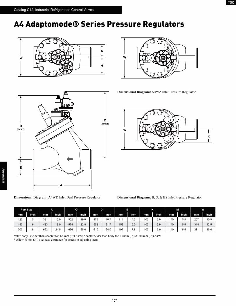
TOC
Catalog C12, Industrial Refrigeration Control Valves
174
Ap
pe
nd
ix B
A4 Adaptomode® Series Pressure Regulators
Port Size A C* D* E K M W
mm inch mm inch mm inch mm inch mm inch mm inch mm inch mm inch
125 5 381 15.0 502 19.8 476 18.7 114 4.5 100 3.9 140 5.5 267 10.5
150 6 483 19.0 578 22.8 552 21.7 152 6.0 100 3.9 140 5.5 318 12.5
200 8 622 24.5 636 25.0 610 24.0 197 7.8 100 3.9 140 5.5 381 15.0
Valve body is wider than adapter for 125mm (5”) A4W; Adapter wider than body for 150mm (6”) & 200mm (8”) A4W
K
S
B
W
W
E
D
A
(A4WZ)
(A4WD)
W
K
C
M
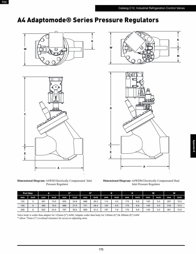
TOC
Catalog C12, Industrial Refrigeration Control Valves
175
Ap
pe
nd
ix B
A4 Adaptomode® Series Pressure Regulators
Port Size A C* D* E K M W
mm inch mm inch mm inch mm inch mm inch mm inch mm inch mm inch
125 5 381 15.0 633 24.9 668 26.3 114 4.5 175 6.9 140 5.5 267 10.5
150 6 483 19.0 686 27.0 721 28.4 152 6.0 175 6.9 140 5.5 318 12.5
200 8 622 24.5 767 30.2 800 31.5 197 7.8 175 6.9 140 5.5 381 15.0
Valve body is wider than adapter for 125mm (5”) A4W; Adapter wider than body for 150mm (6”) & 200mm (8”) A4W
E
D
A
W
K
C
M
E
A
W
K
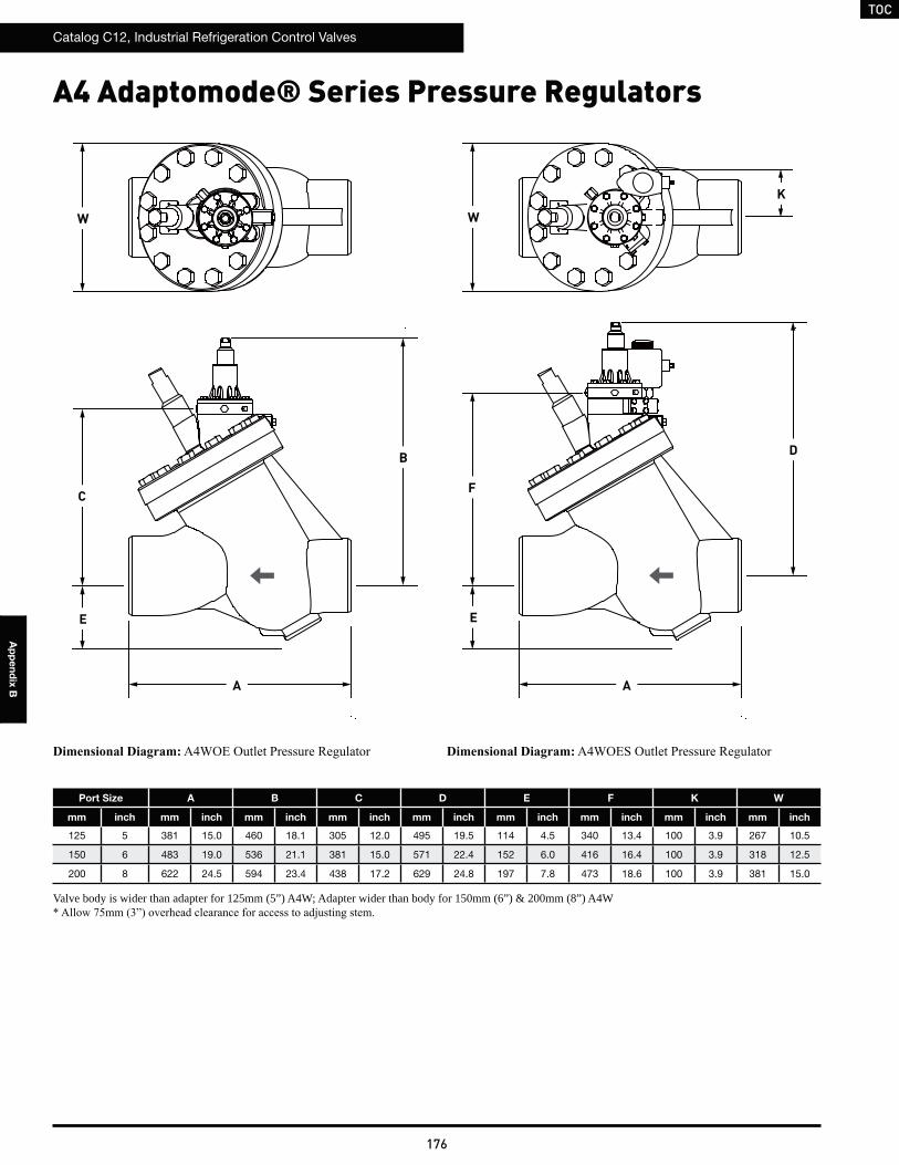
TOC
Catalog C12, Industrial Refrigeration Control Valves
176
Ap
pe
nd
ix B
A4 Adaptomode® Series Pressure Regulators
Port Size A B C D E F K W
mm inch mm inch mm inch mm inch mm inch mm inch mm inch mm inch mm inch
125 5 381 15.0 460 18.1 305 12.0 495 19.5 114 4.5 340 13.4 100 3.9 267 10.5
150 6 483 19.0 536 21.1 381 15.0 571 22.4 152 6.0 416 16.4 100 3.9 318 12.5
200 8 622 24.5 594 23.4 438 17.2 629 24.8 197 7.8 473 18.6 100 3.9 381 15.0
Valve body is wider than adapter for 125mm (5”) A4W; Adapter wider than body for 150mm (6”) & 200mm (8”) A4W
C
B
WW
F
E
D
A A
E
K
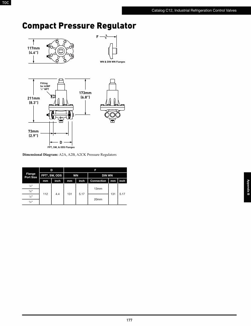
TOC
Catalog C12, Industrial Refrigeration Control Valves
177
Ap
pe
nd
ix B
Compact Pressure Regulator
Flange
Port Size
D F
FPT*, SW, ODS WN DIN WN
mm inch mm inch Connection mm inch
1 ⁄4”
112 4.4 131 5.17
13mm
131 5.173 ⁄8”
1 ⁄2”20mm
3⁄4”
FPT, SW, & ODS Flanges
D
211mm(8.3”)
F
117mm(4.6”)
173mm(6.8”)
Fitting for A2BP1 ⁄4” NPT
73mm(2.9”)
WN & DIN WN Flanges
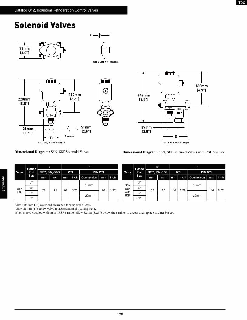
TOC
Catalog C12, Industrial Refrigeration Control Valves
178
Ap
pe
nd
ix B
Valve
Flange
Port
Size
D F
FPT*, SW, ODS WN DIN WN
mm inch mm inch Connection mm inch
S6NS8F
1⁄4”
76 3.0 96 3.77
13mm
96 3.773 ⁄8”
1 ⁄2”20mm
3⁄4”
Allow 100mm (4”) overhead clearance for removal of coil.Allow 25mm (1”) below valve to access manual opening stem.When closed coupled with an 1 2
Strainer
51mm(2.0”)
FPT, SW, & ODS Flanges
D
160mm(6.3”)220mm
(8.8”)
76mm(3.0”)
F
38mm(1.5”)
FPT, SW, & ODS Flanges
D
242mm(9.5”)
160mm(6.3”)
89mm(3.5”)
Solenoid Valves
Valve
Flange
Port
Size
D F
FPT*, SW, ODS WN DIN WN
mm inch mm inch Connection mm inch
S6NS8FwithRSF
1⁄4”
127 5.0 146 5.77
13mm
146 5.773 ⁄8”
1 ⁄2”20mm
3⁄4”
WN & DIN WN Flanges
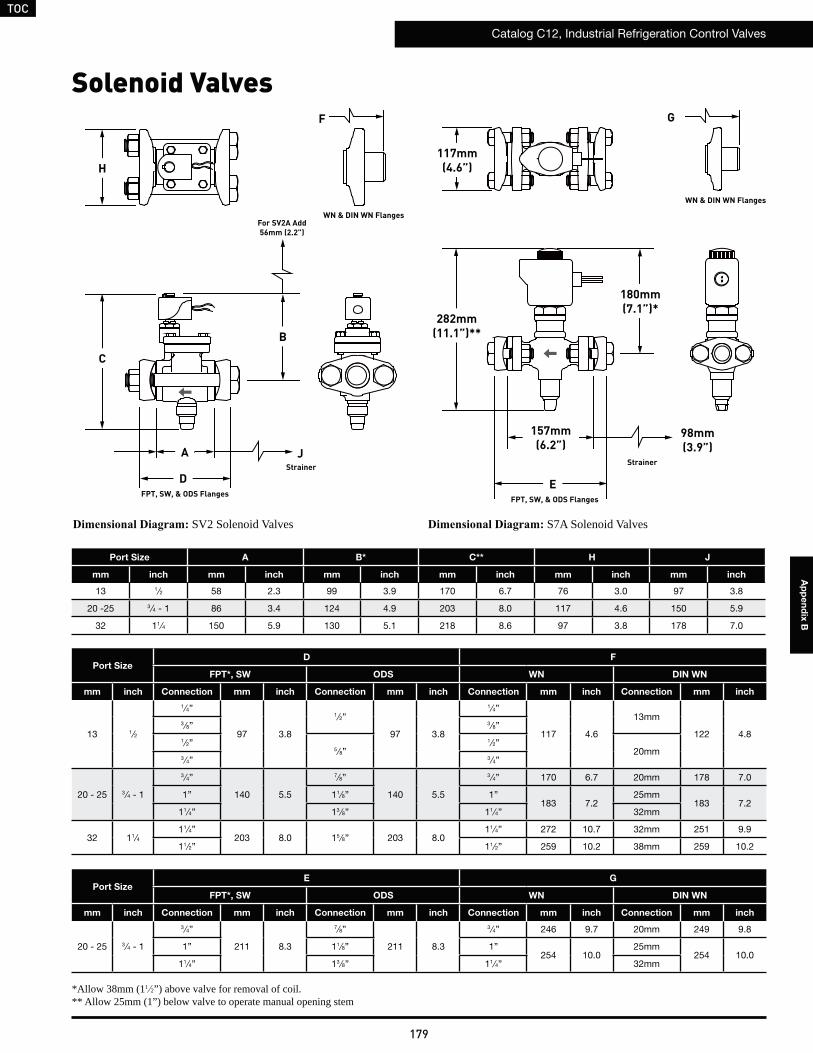
TOC
Catalog C12, Industrial Refrigeration Control Valves
179
Ap
pe
nd
ix B
SV2 Solenoid Valves
JStrainer
FPT, SW, & ODS Flanges
D
A
B
C
H
F
Port Size A B* C** H J
mm inch mm inch mm inch mm inch mm inch mm inch
13 1⁄2 58 2.3 99 3.9 170 6.7 76 3.0 97 3.8
20 -25 3 ⁄4 - 1 86 3.4 124 4.9 203 8.0 117 4.6 150 5.9
32 11⁄4 150 5.9 130 5.1 218 8.6 97 3.8 178 7.0
Port SizeD F
FPT*, SW ODS WN DIN WN
mm inch Connection mm inch Connection mm inch Connection mm inch Connection mm inch
13 1⁄2
1 ⁄4”
97 3.8
1⁄2”
97 3.8
1⁄4”
117 4.6
13mm
122 4.83 ⁄8” 3 ⁄8”
1 ⁄2”5 ⁄8”
1 ⁄2”20mm
3⁄4” 3 ⁄4”
20 - 25 3 ⁄4 - 1
3 ⁄4”
140 5.5
7⁄8”
140 5.5
3 ⁄4” 170 6.7 20mm 178 7.0
1” 11⁄8” 1”183 7.2
25mm183 7.2
11⁄4” 13 ⁄8” 11⁄4” 32mm
32 11⁄411⁄4”
203 8.0 15 ⁄8” 203 8.011⁄4” 272 10.7 32mm 251 9.9
11⁄2” 11⁄2” 259 10.2 38mm 259 10.2
*Allow 38mm (11 2”) above valve for removal of coil.** Allow 25mm (1”) below valve to operate manual opening stem
For SV2A Add56mm (2.2”)
S7A Solenoid Valves
180mm(7.1”)*
282mm(11.1”)**
117mm(4.6”)
157mm(6.2”)
Strainer
98mm(3.9”)
Port SizeE G
FPT*, SW ODS WN DIN WN
mm inch Connection mm inch Connection mm inch Connection mm inch Connection mm inch
20 - 25 3 ⁄4 - 1
3 ⁄4”
211 8.3
7⁄8”
211 8.3
3 ⁄4” 246 9.7 20mm 249 9.8
1” 11⁄8” 1”254 10.0
25mm254 10.0
11⁄4” 13 ⁄8” 11⁄4” 32mm
G
FPT, SW, & ODS Flanges
E
WN & DIN WN Flanges
WN & DIN WN Flanges
Solenoid Valves

TOC
Catalog C12, Industrial Refrigeration Control Valves
180
Ap
pe
nd
ix B
Solenoid Valves
S5A Solenoid Valves S4A Solenoid Valves
H
B
A
C
F
J
FPT, SW, & ODS Flanges
WN & DIN WN Flanges
D
Port Size A B* C** H J K** M
mm inch mm inch mm inch mm inch mm inch mm inch mm inch mm inch
20 -25 3 ⁄4 - 1 164 6.2 147 5.8 376 14.8 117 4.6 150 5.9 – – – –
32 11⁄4 203 8.0 160 6.3 394 15.5 117 4.6 178 7.0 348 13.7 117 4.6
40 - 50 15 ⁄8 - 2 251 9.9 175 6.9 442 17.4 140 5.5 251 9.9 411 16.2 127 5.0
65 21⁄2 252 9.9 180 7.1 467 18.4 159 6.2 315 12.4 437 17.2 137 5.4
75 3 311 12.2 272 10.7 579 22.8 176 7.0 315 12.4 511 20.1 198 7.8
100 4 359 14.1 292 11.5 645 25.4 222 8.9 363 14.3 – – – –
Strainer
3 4” - 2”)
* Allow 25mm (1”) below valve to operate manual opening stem
A
FPT, SW, & ODS Flanges
D
K
M
JStrainer
H
F
WN & DIN WN Flanges
Port SizeD F
FPT*, SW ODS WN DIN WN
mm inch Connection mm inch Connection mm inch Connection mm inch Connection mm inch
20 - 25 3 ⁄4 - 1
3 ⁄4”
211 8.3
7⁄8”
211 8.3
3 ⁄4” 246 9.7 20mm 248 9.8
1” 11⁄8” 1”254 10.0
25mm255 10.0
11⁄4” 13 ⁄8” 11⁄4” 32mm
32 11⁄411⁄4”
254 10.0 15 ⁄8” 254 10.011⁄4” 325 12.8 32mm 304 12.0
11⁄2” 11⁄2” 312 12.3 38mm 313 12.3
40 - 50 15 ⁄8 - 211⁄2”
307 12.121⁄8”
307 12.111⁄2” 366 14.4 38mm 364 14.4
2” 25 ⁄8” 2” 378 14.9 50mm 371 14.6
65 21⁄221⁄2”
318 12.525 ⁄8”
318 12.521⁄2” 389 15.3
65mm 388 15.33” 31⁄8” 3” 406 16.0
75 3 3” 376 14.831⁄8”
376 14.8 3” 465 18.3 75mm 465 18.335 ⁄8”
100 4 4” 432 17.0 41⁄8” 432 17.0 4” 551 21.7 100mm 552 21.7
**Allow 38mm (11 2”) above valve for removal of coil.
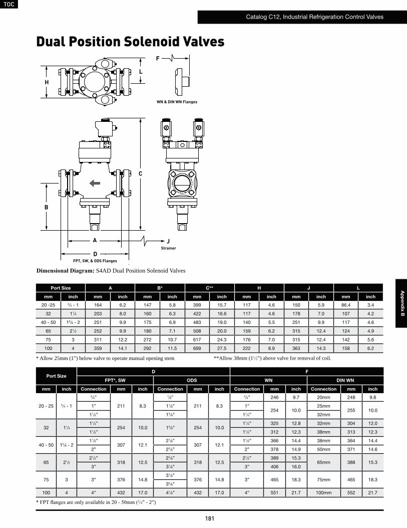
TOC
Catalog C12, Industrial Refrigeration Control Valves
181
Ap
pe
nd
ix B
Dual Position Solenoid Valves
S4AD Dual Position Solenoid Valves
H
B
A
C
F
J
FPT, SW, & ODS Flanges
WN & DIN WN Flanges
D
Port Size A B* C** H J L
mm inch mm inch mm inch mm inch mm inch mm inch mm inch
20 -25 3 ⁄4 - 1 164 6.2 147 5.8 399 15.7 117 4.6 150 5.9 86.4 3.4
32 11⁄4 203 8.0 160 6.3 422 16.6 117 4.6 178 7.0 107 4.2
40 - 50 15 ⁄8 - 2 251 9.9 175 6.9 483 19.0 140 5.5 251 9.9 117 4.6
65 21⁄2 252 9.9 180 7.1 508 20.0 159 6.2 315 12.4 124 4.9
75 3 311 12.2 272 10.7 617 24.3 176 7.0 315 12.4 142 5.6
100 4 359 14.1 292 11.5 699 27.5 222 8.9 363 14.3 158 6.2
Strainer
3 4” - 2”)
* Allow 25mm (1”) below valve to operate manual opening stem
Port SizeD F
FPT*, SW ODS WN DIN WN
mm inch Connection mm inch Connection mm inch Connection mm inch Connection mm inch
20 - 25 3 ⁄4 - 1
3 ⁄4”
211 8.3
7⁄8”
211 8.3
3 ⁄4” 246 9.7 20mm 248 9.8
1” 11⁄8” 1”254 10.0
25mm255 10.0
11⁄4” 13 ⁄8” 11⁄4” 32mm
32 11⁄411⁄4”
254 10.0 15 ⁄8” 254 10.011⁄4” 325 12.8 32mm 304 12.0
11⁄2” 11⁄2” 312 12.3 38mm 313 12.3
40 - 50 15 ⁄8 - 211⁄2”
307 12.121⁄8”
307 12.111⁄2” 366 14.4 38mm 364 14.4
2” 25 ⁄8” 2” 378 14.9 50mm 371 14.6
65 21⁄221⁄2”
318 12.525 ⁄8”
318 12.521⁄2” 389 15.3
65mm 388 15.33” 31⁄8” 3” 406 16.0
75 3 3” 376 14.831⁄8”
376 14.8 3” 465 18.3 75mm 465 18.335 ⁄8”
100 4 4” 432 17.0 41⁄8” 432 17.0 4” 551 21.7 100mm 552 21.7
**Allow 38mm (11 2”) above valve for removal of coil.
L
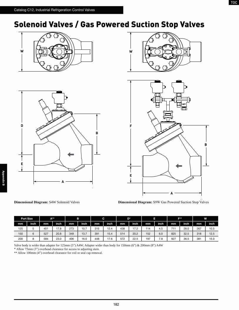
TOC
Catalog C12, Industrial Refrigeration Control Valves
182
Ap
pe
nd
ix B
Solenoid Valves / Gas Powered Suction Stop Valves
B
W
Port Size A** B C D* E F** W
mm inch mm inch mm inch mm inch mm inch mm inch mm inch mm inch
125 5 451 17.8 273 10.7 315 12.4 438 17.2 114 4.5 711 28.0 267 10.5
150 6 527 20.8 349 13.7 391 15.4 514 20.2 152 6.0 825 32.5 318 12.5
200 8 584 23.0 406 16.0 448 17.6 572 22.5 197 7.8 927 36.5 381 15.0
Valve body is wider than adapter for 125mm (5”) A4W; Adapter wider than body for 150mm (6”) & 200mm (8”) A4W
** Allow 100mm (4”) overhead clearance for coil or seal cap removal.
E
D
A
B
W
E
F
A
S4W Solenoid Valves
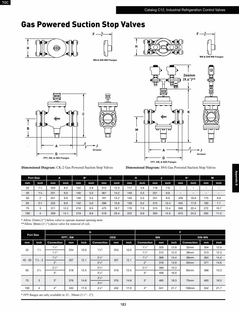
TOC
Catalog C12, Industrial Refrigeration Control Valves
183
Ap
pe
nd
ix B
Gas Powered Suction Stop Valves
H
A
KC
F
J
FPT, SW, & ODS Flanges
WN & DIN WN Flanges
D
Strainer
H
F
A
FPT, SW, & ODS FlangesD
JStrainer
B M
WN & DIN WN Flanges
Port Size A B* C H J K* M
mm inch mm inch mm inch mm inch mm inch mm inch mm inch mm inch
32 11⁄4 203 8.0 122 4.8 312 12.3 117 4.6 178 7.0 – – – –
40 15 ⁄8 251 9.9 140 5.5 361 14.2 140 5.5 251 9.9 – – – –
50 2 251 9.9 140 5.5 161 14.2 140 5.5 251 9.9 429 16.9 175 6.9
65 21⁄2 252 9.9 142 5.6 396 15.6 159 6.2 315 12.4 455 17.9 180 7.1
75 3 311 12.2 216 8.5 475 18.7 176 7.0 315 12.4 569 22.4 272 10.7
100 4 359 14.1 219 8.6 518 20.4 222 8.9 363 14.3 615 24.2 292 11.5
1 4” - 2”)
* Allow 25mm (1”) below valve to operate manual opening stem**Allow 38mm (11 2”) above valve for removal of coil.
Port SizeD F
FPT*, SW ODS WN DIN WN
mm inch Connection mm inch Connection mm inch Connection mm inch Connection mm inch
32 11⁄411⁄4”
254 10.0 15 ⁄8” 254 10.011⁄4” 325 12.8 32mm 304 12.0
11⁄2” 11⁄2” 312 12.3 38mm 313 12.3
40 - 50 15 ⁄8 - 211⁄2”
307 12.121⁄8”
307 12.111⁄2” 366 14.4 38mm 364 14.4
2” 25 ⁄8” 2” 378 14.9 50mm 371 14.6
65 21⁄221⁄2”
318 12.525 ⁄8”
318 12.521⁄2” 389 15.3
65mm 388 15.33” 31⁄8” 3” 406 16.0
75 3 3” 376 14.831⁄8”
376 14.8 3” 465 18.3 75mm 465 18.335 ⁄8”
100 4 4” 432 17.0 41⁄8” 432 17.0 4” 551 21.7 100mm 552 21.7
244mm(9.6”)**
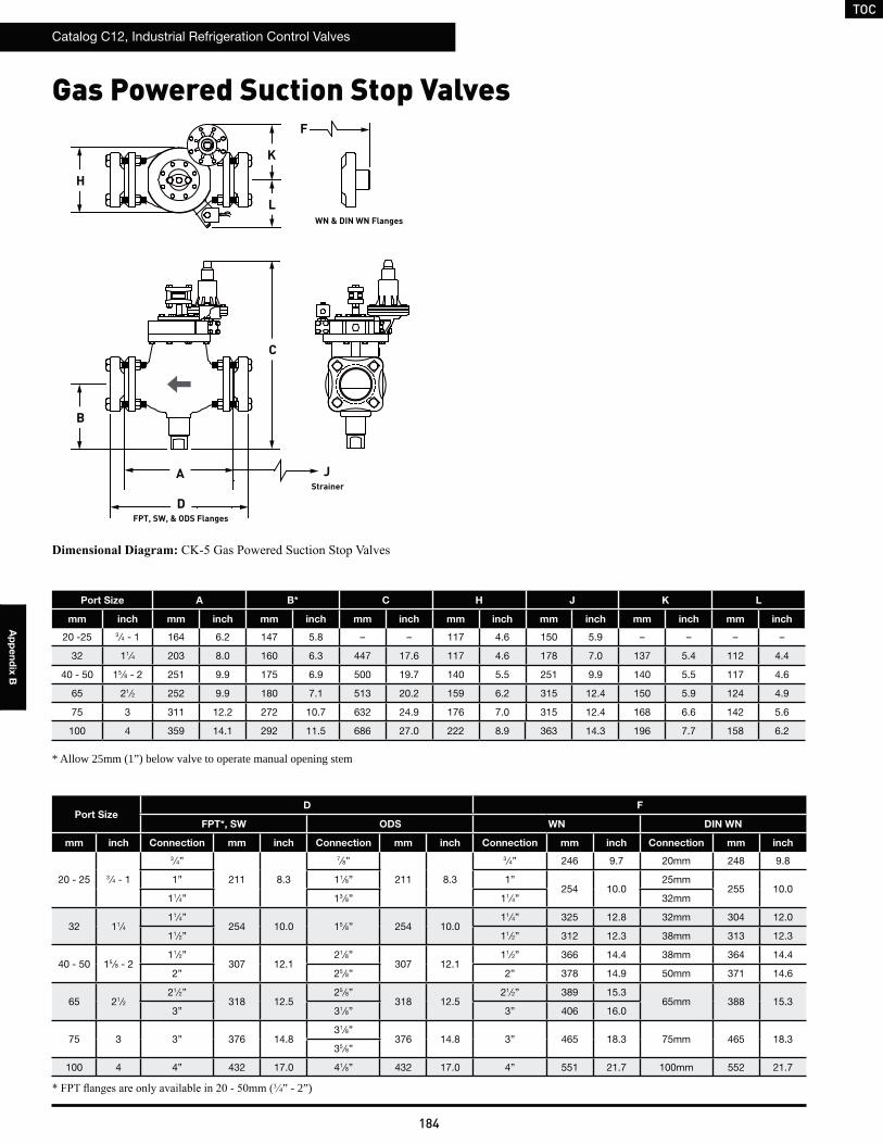
TOC
Catalog C12, Industrial Refrigeration Control Valves
184
Ap
pe
nd
ix B
H
B
A
C
F
J
FPT, SW, & ODS Flanges
WN & DIN WN Flanges
D
Port Size A B* C H J K L
mm inch mm inch mm inch mm inch mm inch mm inch mm inch mm inch
20 -25 3 ⁄4 - 1 164 6.2 147 5.8 – – 117 4.6 150 5.9 – – – –
32 11⁄4 203 8.0 160 6.3 447 17.6 117 4.6 178 7.0 137 5.4 112 4.4
40 - 50 15 ⁄8 - 2 251 9.9 175 6.9 500 19.7 140 5.5 251 9.9 140 5.5 117 4.6
65 21⁄2 252 9.9 180 7.1 513 20.2 159 6.2 315 12.4 150 5.9 124 4.9
75 3 311 12.2 272 10.7 632 24.9 176 7.0 315 12.4 168 6.6 142 5.6
100 4 359 14.1 292 11.5 686 27.0 222 8.9 363 14.3 196 7.7 158 6.2
Strainer
3 4” - 2”)
* Allow 25mm (1”) below valve to operate manual opening stem
K
Port SizeD F
FPT*, SW ODS WN DIN WN
mm inch Connection mm inch Connection mm inch Connection mm inch Connection mm inch
20 - 25 3 ⁄4 - 1
3 ⁄4”
211 8.3
7⁄8”
211 8.3
3 ⁄4” 246 9.7 20mm 248 9.8
1” 11⁄8” 1”254 10.0
25mm255 10.0
11⁄4” 13 ⁄8” 11⁄4” 32mm
32 11⁄411⁄4”
254 10.0 15 ⁄8” 254 10.011⁄4” 325 12.8 32mm 304 12.0
11⁄2” 11⁄2” 312 12.3 38mm 313 12.3
40 - 50 15 ⁄8 - 211⁄2”
307 12.121⁄8”
307 12.111⁄2” 366 14.4 38mm 364 14.4
2” 25 ⁄8” 2” 378 14.9 50mm 371 14.6
65 21⁄221⁄2”
318 12.525 ⁄8”
318 12.521⁄2” 389 15.3
65mm 388 15.33” 31⁄8” 3” 406 16.0
75 3 3” 376 14.831⁄8”
376 14.8 3” 465 18.3 75mm 465 18.335 ⁄8”
100 4 4” 432 17.0 41⁄8” 432 17.0 4” 551 21.7 100mm 552 21.7
L
Gas Powered Suction Stop Valves
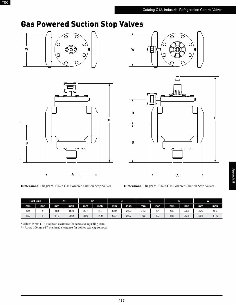
TOC
Catalog C12, Industrial Refrigeration Control Valves
185
Ap
pe
nd
ix B
Gas Powered Suction Stop Valves
Port Size A* B* C D E W
mm inch mm inch mm inch mm inch mm inch mm inch mm inch
125 5 381 15.0 297 11.7 589 23.2 213 8.4 589 23.2 229 9.0
150 6 513 20.2 356 14.0 627 24.7 196 7.7 681 26.8 295 11.6
** Allow 100mm (4”) overhead clearance for coil or seal cap removal.
B
W
EC
A
B
W
A
D
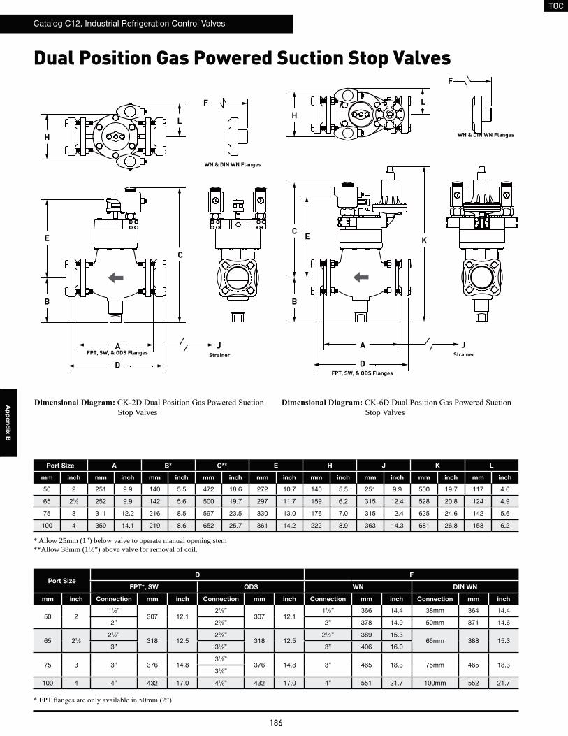
TOC
Catalog C12, Industrial Refrigeration Control Valves
186
Ap
pe
nd
ix B
Stop Valves
Dual Position Gas Powered Suction Stop Valves
H
A
K
C
F
J
FPT, SW, & ODS Flanges
WN & DIN WN Flanges
DStrainer
H
F
AFPT, SW, & ODS Flanges
D
JStrainer
B
WN & DIN WN Flanges
Port Size A B* C** E H J K L
mm inch mm inch mm inch mm inch mm inch mm inch mm inch mm inch mm inch
50 2 251 9.9 140 5.5 472 18.6 272 10.7 140 5.5 251 9.9 500 19.7 117 4.6
65 21⁄2 252 9.9 142 5.6 500 19.7 297 11.7 159 6.2 315 12.4 528 20.8 124 4.9
75 3 311 12.2 216 8.5 597 23.5 330 13.0 176 7.0 315 12.4 625 24.6 142 5.6
100 4 359 14.1 219 8.6 652 25.7 361 14.2 222 8.9 363 14.3 681 26.8 158 6.2
* Allow 25mm (1”) below valve to operate manual opening stem**Allow 38mm (11 2”) above valve for removal of coil.
Port SizeD F
FPT*, SW ODS WN DIN WN
mm inch Connection mm inch Connection mm inch Connection mm inch Connection mm inch
50 211⁄2”
307 12.121⁄8”
307 12.111⁄2” 366 14.4 38mm 364 14.4
2” 25 ⁄8” 2” 378 14.9 50mm 371 14.6
65 21⁄221⁄2”
318 12.525 ⁄8”
318 12.521⁄2” 389 15.3
65mm 388 15.33” 31⁄8” 3” 406 16.0
75 3 3” 376 14.831⁄8”
376 14.8 3” 465 18.3 75mm 465 18.335 ⁄8”
100 4 4” 432 17.0 41⁄8” 432 17.0 4” 551 21.7 100mm 552 21.7
L
E
Stop Valves
L
B
EC
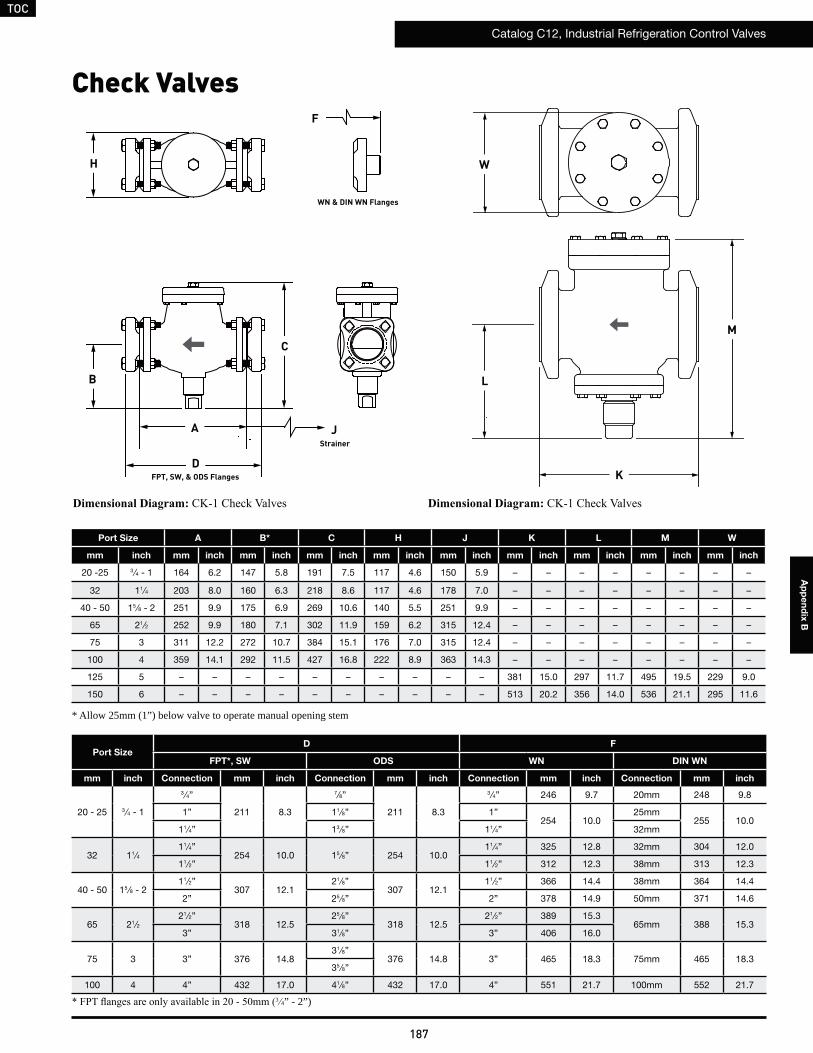
TOC
Catalog C12, Industrial Refrigeration Control Valves
187
Ap
pe
nd
ix B
Check Valves
C
Port Size A B* C H J K L M W
mm inch mm inch mm inch mm inch mm inch mm inch mm inch mm inch mm inch mm inch
20 -25 3 ⁄4 - 1 164 6.2 147 5.8 191 7.5 117 4.6 150 5.9 – – – – – – – –
32 11⁄4 203 8.0 160 6.3 218 8.6 117 4.6 178 7.0 – – – – – – – –
40 - 50 15 ⁄8 - 2 251 9.9 175 6.9 269 10.6 140 5.5 251 9.9 – – – – – – – –
65 21⁄2 252 9.9 180 7.1 302 11.9 159 6.2 315 12.4 – – – – – – – –
75 3 311 12.2 272 10.7 384 15.1 176 7.0 315 12.4 – – – – – – – –
100 4 359 14.1 292 11.5 427 16.8 222 8.9 363 14.3 – – – – – – – –
125 5 – – – – – – – – – – 381 15.0 297 11.7 495 19.5 229 9.0
150 6 – – – – – – – – – – 513 20.2 356 14.0 536 21.1 295 11.6
3 4” - 2”)
* Allow 25mm (1”) below valve to operate manual opening stem
A
FPT, SW, & ODS FlangesD
JStrainer
H
F
WN & DIN WN Flanges
Port SizeD F
FPT*, SW ODS WN DIN WN
mm inch Connection mm inch Connection mm inch Connection mm inch Connection mm inch
20 - 25 3 ⁄4 - 1
3 ⁄4”
211 8.3
7⁄8”
211 8.3
3 ⁄4” 246 9.7 20mm 248 9.8
1” 11⁄8” 1”254 10.0
25mm255 10.0
11⁄4” 13 ⁄8” 11⁄4” 32mm
32 11⁄411⁄4”
254 10.0 15 ⁄8” 254 10.011⁄4” 325 12.8 32mm 304 12.0
11⁄2” 11⁄2” 312 12.3 38mm 313 12.3
40 - 50 15 ⁄8 - 211⁄2”
307 12.121⁄8”
307 12.111⁄2” 366 14.4 38mm 364 14.4
2” 25 ⁄8” 2” 378 14.9 50mm 371 14.6
65 21⁄221⁄2”
318 12.525 ⁄8”
318 12.521⁄2” 389 15.3
65mm 388 15.33” 31⁄8” 3” 406 16.0
75 3 3” 376 14.831⁄8”
376 14.8 3” 465 18.3 75mm 465 18.335 ⁄8”
100 4 4” 432 17.0 41⁄8” 432 17.0 4” 551 21.7 100mm 552 21.7
B
W
K
L
M
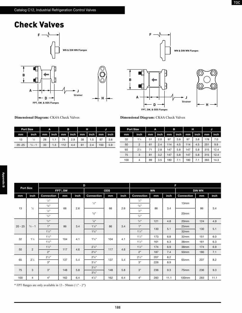
TOC
Catalog C12, Industrial Refrigeration Control Valves
188
Ap
pe
nd
ix B
Check Valves
Port Size A B H J
mm inch mm inch mm inch mm inch mm inch
13 1⁄2 28 1.1 74 2.9 38 1.5 97 3.8
20 -25 3 ⁄4 - 1 33 1.3 112 4.4 61 2.4 150 5.9
Port SizeD F
FPT*, SW ODS WN DIN WN
mm inch Connection mm inch Connection mm inch Connection mm inch Connection mm inch
13 1⁄2
1 ⁄4”
66 2.6
1⁄2”
66 2.6
1⁄4”
86 3.4
13mm
86 3.43 ⁄8” 3 ⁄8”
1 ⁄2”5 ⁄8”
1 ⁄2”20mm
3⁄4” 3 ⁄4”
20 - 25 3 ⁄4 - 1
3 ⁄4”
86 3.4
7⁄8”
86 3.4
3 ⁄4” 121 4.8 20mm 124 4.9
1” 11⁄8” 1”130 5.1
25mm130 5.1
11⁄4” 13 ⁄8” 11⁄4” 32mm
32 11⁄411⁄4”
104 4.1 15 ⁄8” 104 4.111⁄4” 173 6.8 32mm 151 6.0
11⁄2” 11⁄2” 161 6.3 38mm 161 6.3
50 211⁄2”
117 4.621⁄8”
117 4.611⁄2” 174 6.9 38mm 174 6.9
2” 25 ⁄8” 2” 187 7.4 50mm 180 7.1
65 21⁄221⁄2”
137 5.425 ⁄8”
137 5.421⁄2” 207 8.2
65mm 207 8.23” 31⁄8” 3” 226 8.9
75 3 3” 148 5.831⁄8”
148 5.8 3” 236 9.3 75mm 236 9.335 ⁄8”
100 4 4” 162 6.4 41⁄8” 162 6.4 4” 283 11.1 100mm 283 11.1
JStrainer
JStrainer
F F
WN & DIN WN Flanges WN & DIN WN Flanges
A
AFPT, SW, & ODS Flanges
D
FPT, SW, & ODS Flanges
D
BB
H
H
Port Size A B H J
mm inch mm inch mm inch mm inch mm inch
32 11⁄4 51 2.0 97 3.8 97 3.8 178 7.0
50 2 61 2.4 114 4.5 114 4.5 251 9.9
65 21⁄2 71 2.8 147 5.8 147 5.8 315 12.4
75 3 81 3.2 147 5.8 147 5.8 315 12.4
100 4 89 3.5 180 7.1 180 7.1 363 14.3
1 2” - 2”)
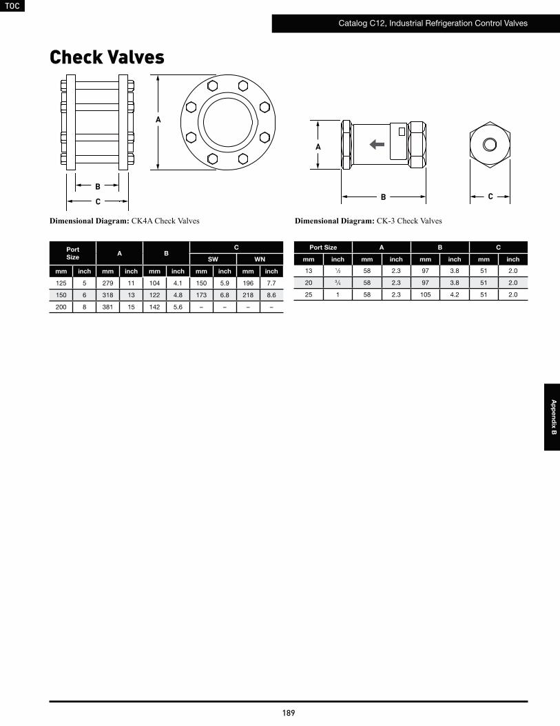
TOC
Catalog C12, Industrial Refrigeration Control Valves
189
Ap
pe
nd
ix B
Port Size A B C
mm inch mm inch mm inch mm inch
13 1⁄2 58 2.3 97 3.8 51 2.0
20 3 ⁄4 58 2.3 97 3.8 51 2.0
25 1 58 2.3 105 4.2 51 2.0
B
A
C
Check Valves
A
B
Port
SizeA B
C
SW WN
mm inch mm inch mm inch mm inch mm inch
125 5 279 11 104 4.1 150 5.9 196 7.7
150 6 318 13 122 4.8 173 6.8 218 8.6
200 8 381 15 142 5.6 – – – –
C
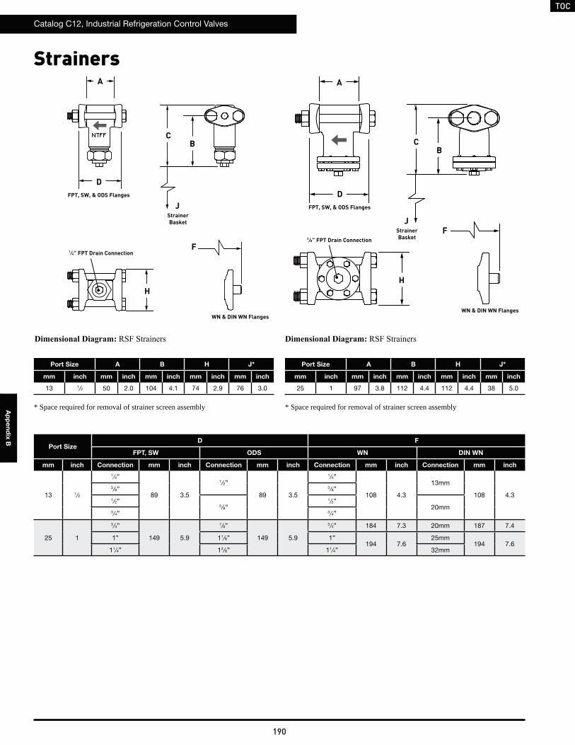
TOC
Catalog C12, Industrial Refrigeration Control Valves
190
Ap
pe
nd
ix B
H
B
A
C
F
FPT, SW, & ODS Flanges
WN & DIN WN Flanges
D
A
FPT, SW, & ODS Flanges
D
CB
F
H
WN & DIN WN Flanges
JStrainerBasket J
StrainerBasket
Port Size A B H J*
mm inch mm inch mm inch mm inch mm inch
13 1⁄2 50 2.0 104 4.1 74 2.9 76 3.0
Port SizeD F
FPT, SW ODS WN DIN WN
mm inch Connection mm inch Connection mm inch Connection mm inch Connection mm inch
13 1⁄2
1 ⁄4”
89 3.5
1⁄2”
89 3.5
1⁄4”
108 4.3
13mm
108 4.33 ⁄8” 3 ⁄8”
1 ⁄2”5 ⁄8”
1 ⁄2”20mm
3⁄4” 3 ⁄4”
25 1
3 ⁄4”
149 5.9
7⁄8”
149 5.9
3 ⁄4” 184 7.3 20mm 187 7.4
1” 11⁄8” 1”194 7.6
25mm194 7.6
11⁄4” 13 ⁄8” 11⁄4” 32mm
Port Size A B H J*
mm inch mm inch mm inch mm inch mm inch
25 1 97 3.8 112 4.4 112 4.4 38 5.0
Strainers
* Space required for removal of strainer screen assembly * Space required for removal of strainer screen assembly
1 ⁄4” FPT Drain Connection
3 ⁄8” FPT Drain Connection
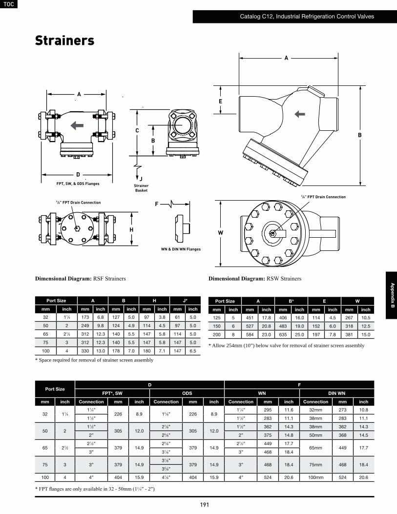
TOC
Catalog C12, Industrial Refrigeration Control Valves
191
Ap
pe
nd
ix B
1 4” - 2”)
Port SizeD F
FPT*, SW ODS WN DIN WN
mm inch Connection mm inch Connection mm inch Connection mm inch Connection mm inch
32 11⁄411⁄4”
226 8.9 15 ⁄8” 226 8.911⁄4” 295 11.6 32mm 273 10.8
11⁄2” 11⁄2” 283 11.1 38mm 283 11.1
50 211⁄2”
305 12.021⁄8”
305 12.011⁄2” 362 14.3 38mm 362 14.3
2” 25 ⁄8” 2” 375 14.8 50mm 368 14.5
65 21⁄221⁄2”
379 14.925 ⁄8”
379 14.921⁄2” 449 17.7
65mm 449 17.73” 31⁄8” 3” 468 18.4
75 3 3” 379 14.931⁄8”
379 14.9 3” 468 18.4 75mm 468 18.435 ⁄8”
100 4 4” 404 15.9 41⁄8” 404 15.9 4” 524 20.6 100mm 524 20.6
Port Size A B H J*
mm inch mm inch mm inch mm inch mm inch
32 11⁄4 173 6.8 127 5.0 97 3.8 61 5.0
50 2 249 9.8 124 4.9 114 4.5 97 5.0
65 21⁄2 312 12.3 140 5.5 147 5.8 114 5.0
75 3 312 12.3 140 5.5 147 5.8 147 5.0
100 4 330 13.0 178 7.0 180 7.1 147 6.5
* Space required for removal of strainer screen assembly
A
FPT, SW, & ODS Flanges
D
C
B
F
H
WN & DIN WN Flanges
JStrainerBasket
B
W
Port Size A B* E W
mm inch mm inch mm inch mm inch mm inch
125 5 451 17.8 406 16.0 114 4.5 267 10.5
150 6 527 20.8 483 19.0 152 6.0 318 12.5
200 8 584 23.0 635 25.0 197 7.8 381 15.0
E
StrainersA
* Allow 254mm (10”) below valve for removal of strainer screen assembly
3 ⁄8” FPT Drain Connection
3 ⁄8” FPT Drain Connection
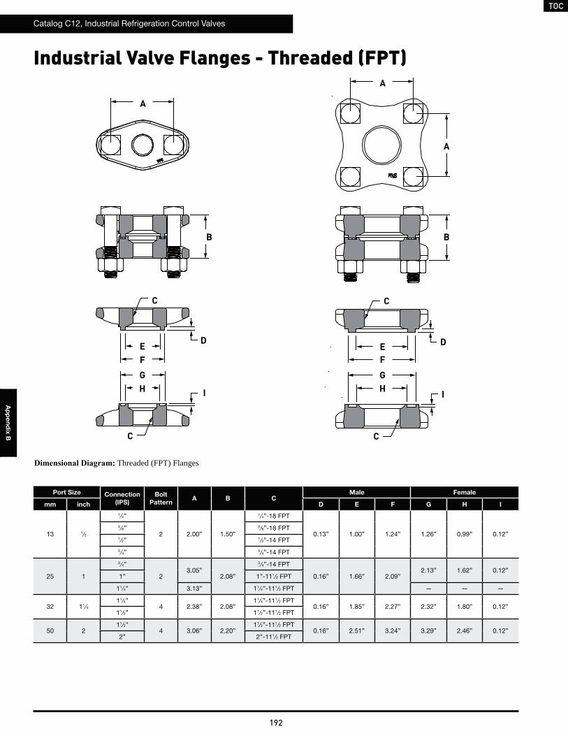
TOC
Catalog C12, Industrial Refrigeration Control Valves
192
Ap
pe
nd
ix B
Industrial Valve Flanges - Threaded (FPT)
Port Size Connection
(IPS)
Bolt
PatternA B C
Male Female
mm inch D E F G H I
13 1⁄2
1 ⁄4”
2 2.00” 1.50”
1⁄4”-18 FPT
0.13” 1.00” 1.24” 1.26” 0.99” 0.12”3 ⁄8” 3 ⁄8”-18 FPT
1⁄2” 1 ⁄2”-14 FPT
3 ⁄4” 3 ⁄4”-14 FPT
25 1
3 ⁄4”
23.05”
2.08”
3 ⁄4”-14 FPT
0.16” 1.66” 2.09”2.13” 1.62” 0.12”
1” 1”-111⁄2 FPT
11⁄4” 3.13” 11⁄4”-111⁄2 FPT — — —
32 11⁄411⁄4”
4 2.38” 2.08”11⁄4”-111⁄2 FPT
0.16” 1.85” 2.27” 2.32” 1.80” 0.12”11⁄2” 11⁄2”-111⁄2 FPT
50 211⁄2”
4 3.06” 2.20”11⁄2”-111⁄2 FPT
0.16” 2.51” 3.24” 3.29” 2.46” 0.12”2” 2”-111⁄2 FPT
Threaded (FPT) Flanges
A
D D
B B
A
A
EF
GH I
C
EF
GH
C
C
C
I
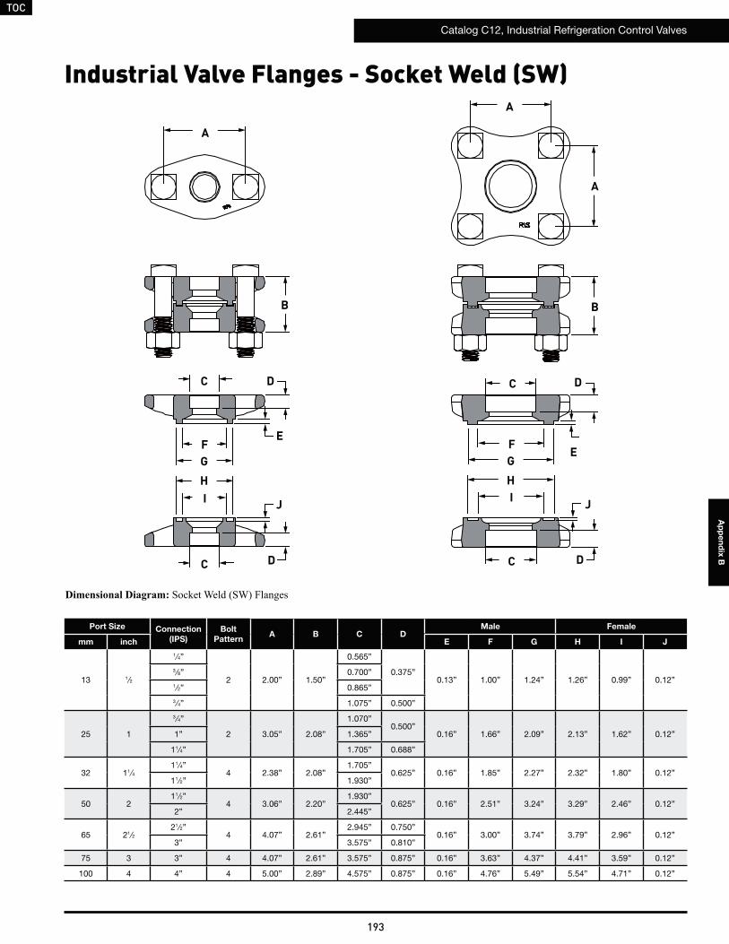
TOC
Catalog C12, Industrial Refrigeration Control Valves
193
Ap
pe
nd
ix B
Industrial Valve Flanges - Socket Weld (SW)
Port Size Connection
(IPS)
Bolt
PatternA B C D
Male Female
mm inch E F G H I J
13 1⁄2
1 ⁄4”
2 2.00” 1.50”
0.565”
0.375”0.13” 1.00” 1.24” 1.26” 0.99” 0.12”
3 ⁄8” 0.700”
1⁄2” 0.865”
3 ⁄4” 1.075” 0.500”
25 1
3 ⁄4”
2 3.05” 2.08”
1.070”0.500”
0.16” 1.66” 2.09” 2.13” 1.62” 0.12”1” 1.365”
11⁄4” 1.705” 0.688”
32 11⁄411⁄4”
4 2.38” 2.08”1.705”
0.625” 0.16” 1.85” 2.27” 2.32” 1.80” 0.12”11⁄2” 1.930”
50 211⁄2”
4 3.06” 2.20”1.930”
0.625” 0.16” 2.51” 3.24” 3.29” 2.46” 0.12”2” 2.445”
65 21⁄221⁄2”
4 4.07” 2.61”2.945” 0.750”
0.16” 3.00” 3.74” 3.79” 2.96” 0.12”3” 3.575” 0.810”
75 3 3” 4 4.07” 2.61” 3.575” 0.875” 0.16” 3.63” 4.37” 4.41” 3.59” 0.12”
100 4 4” 4 5.00” 2.89” 4.575” 0.875” 0.16” 4.76” 5.49” 5.54” 4.71” 0.12”
A
A
A
B B
C
C C
C
D
D D
D
EFG
HI
FG
HI J J
E
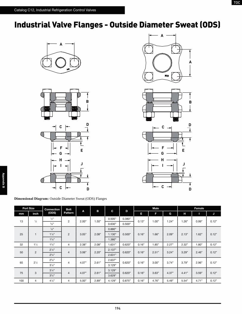
TOC
Catalog C12, Industrial Refrigeration Control Valves
194
Ap
pe
nd
ix B
Industrial Valve Flanges - Outside Diameter Sweat (ODS)
Port Size Connection
(ODS)
Bolt
PatternA B C D
Male Female
mm inch E F G H I J
13 1⁄21 ⁄2”
2 2.00” 1.50”0.505” 0.380”
0.13” 1.00” 1.24” 1.26” 0.99” 0.12”5 ⁄8” 0.630” 0.500”
25 1
7⁄8”
2 3.05” 2.08”
0.880”
0.500” 0.16” 1.66” 2.09” 2.13” 1.62” 0.12”11⁄8” 1.130”
13 ⁄8” 1.380”
32 11⁄4 15 ⁄8” 4 2.38” 2.08” 1.631” 0.620” 0.16” 1.85” 2.27” 2.32” 1.80” 0.12”
50 221⁄8”
4 3.06” 2.20”2.137”
0.620” 0.16” 2.51” 3.24” 3.29” 2.46” 0.12”25 ⁄8” 2.631”
65 21⁄225 ⁄8”
4 4.07” 2.61”2.637”
0.620” 0.16” 3.00” 3.74” 3.79” 2.96” 0.12”31⁄8” 3.129”
75 331⁄8”
4 4.07” 2.61”3.129”
0.620” 0.16” 3.63” 4.37” 4.41” 3.59” 0.12”35 ⁄8” 3.629”
100 4 41⁄8” 4 5.00” 2.89” 4.129” 0.875” 0.16” 4.76” 5.49” 5.54” 4.71” 0.12”
Outside Diameter Sweat (ODS) Flanges
A
A
A
B B
C
C C
C
D
D D
D
EFG
HI
FG
HI J J
E
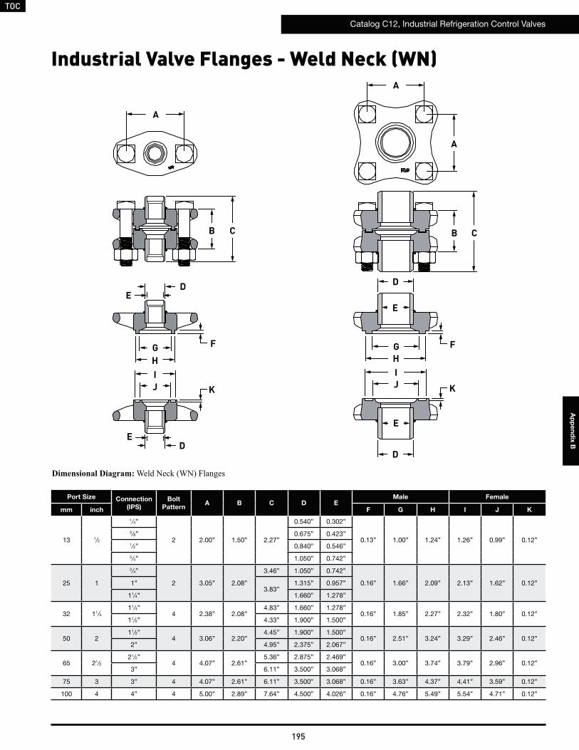
TOC
Catalog C12, Industrial Refrigeration Control Valves
195
Ap
pe
nd
ix B
Industrial Valve Flanges - Weld Neck (WN)
Port Size Connection
(IPS)
Bolt
PatternA B C D E
Male Female
mm inch F G H I J K
13 1⁄2
1 ⁄4”
2 2.00” 1.50” 2.27”
0.540” 0.302”
0.13” 1.00” 1.24” 1.26” 0.99” 0.12”3 ⁄8” 0.675” 0.423”
1⁄2” 0.840” 0.546”
3 ⁄4” 1.050” 0.742”
25 1
3 ⁄4”
2 3.05” 2.08”
3.46” 1.050” 0.742”
0.16” 1.66” 2.09” 2.13” 1.62” 0.12”1”3.83”
1.315” 0.957”
11⁄4” 1.660” 1.278”
32 11⁄411⁄4”
4 2.38” 2.08”4.83” 1.660” 1.278”
0.16” 1.85” 2.27” 2.32” 1.80” 0.12”11⁄2” 4.33” 1.900” 1.500”
50 211⁄2”
4 3.06” 2.20”4.45” 1.900” 1.500”
0.16” 2.51” 3.24” 3.29” 2.46” 0.12”2” 4.95” 2.375” 2.067”
65 21⁄221⁄2”
4 4.07” 2.61”5.36” 2.875” 2.469”
0.16” 3.00” 3.74” 3.79” 2.96” 0.12”3” 6.11” 3.500” 3.068”
75 3 3” 4 4.07” 2.61” 6.11” 3.500” 3.068” 0.16” 3.63” 4.37” 4.41” 3.59” 0.12”
100 4 4” 4 5.00” 2.89” 7.64” 4.500” 4.026” 0.16” 4.76” 5.49” 5.54” 4.71” 0.12”
A
A
A
B BC C
DE
D
E
DD
EE
GHIJ K
F GHIJ K
F
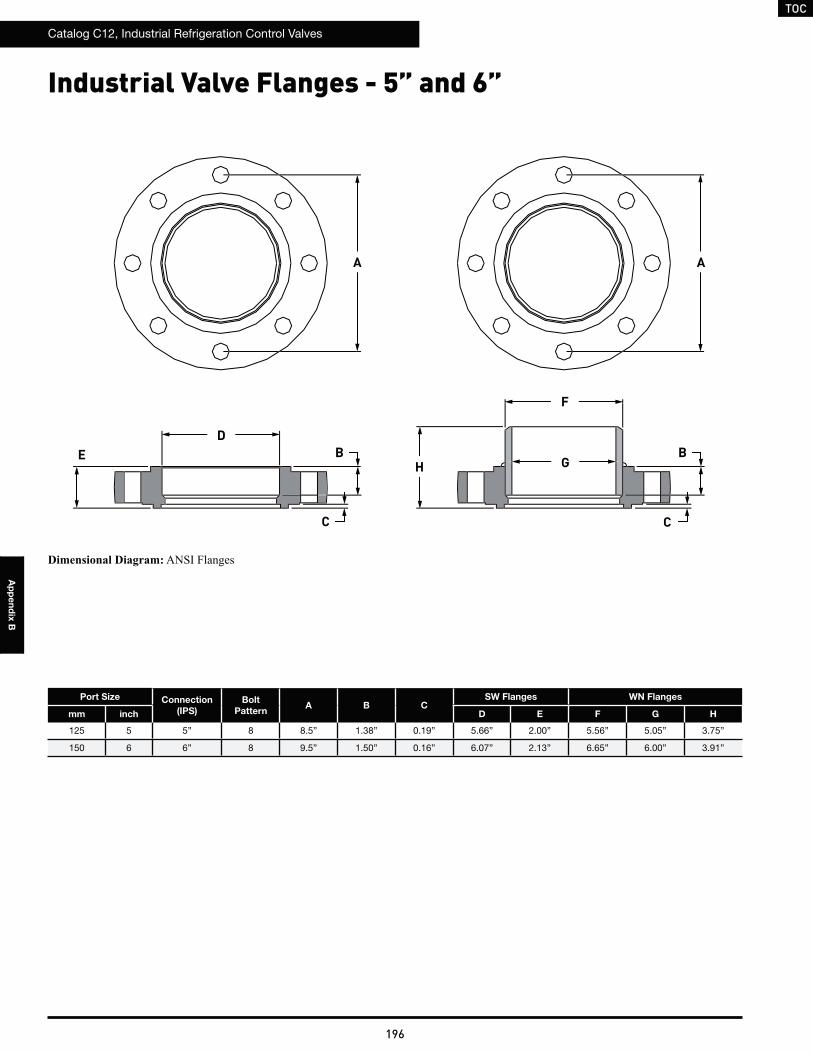
TOC
Catalog C12, Industrial Refrigeration Control Valves
196
Ap
pe
nd
ix B
Industrial Valve Flanges - 5” and 6”
Port Size Connection
(IPS)
Bolt
PatternA B C
SW Flanges WN Flanges
mm inch D E F G H
125 5 5” 8 8.5” 1.38” 0.19” 5.66” 2.00” 5.56” 5.05” 3.75”
150 6 6” 8 9.5” 1.50” 0.16” 6.07” 2.13” 6.65” 6.00” 3.91”
E
A A
B
F
CC
H
D
GB
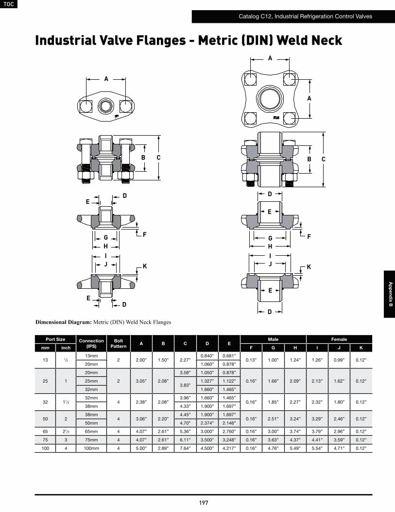
TOC
Catalog C12, Industrial Refrigeration Control Valves
197
Ap
pe
nd
ix B
Industrial Valve Flanges - Metric (DIN) Weld Neck
Port Size Connection
(IPS)
Bolt
PatternA B C D E
Male Female
mm inch F G H I J K
13 1⁄213mm
2 2.00” 1.50” 2.27”0.840” 0.681”
0.13” 1.00” 1.24” 1.26” 0.99” 0.12”20mm 1.060” 0.878”
25 1
20mm
2 3.05” 2.08”
3.58” 1.050” 0.878”
0.16” 1.66” 2.09” 2.13” 1.62” 0.12”25mm3.83”
1.327” 1.122”
32mm 1.660” 1.465”
32 11⁄432mm
4 2.38” 2.08”3.96” 1.660” 1.465”
0.16” 1.85” 2.27” 2.32” 1.80” 0.12”38mm 4.33” 1.900” 1.697”
50 238mm
4 3.06” 2.20”4.45” 1.900” 1.697”
0.16” 2.51” 3.24” 3.29” 2.46” 0.12”50mm 4.70” 2.374” 2.146”
65 21⁄2 65mm 4 4.07” 2.61” 5.36” 3.000” 2.760” 0.16” 3.00” 3.74” 3.79” 2.96” 0.12”
75 3 75mm 4 4.07” 2.61” 6.11” 3.500” 3.248” 0.16” 3.63” 4.37” 4.41” 3.59” 0.12”
100 4 100mm 4 5.00” 2.89” 7.64” 4.500” 4.217” 0.16” 4.76” 5.49” 5.54” 4.71” 0.12”
A
A
A
B BC C
DE
D
E
DD
EE
GHIJ K
F GHIJ K
F
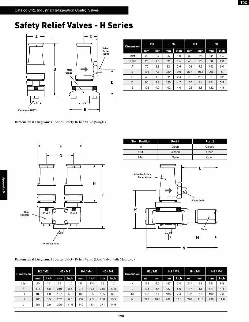
TOC
Catalog C12, Industrial Refrigeration Control Valves
198
Ap
pe
nd
ix B
Safety Relief Valves - H Series
DimensionH2 / M2 H3 / M3 H4 / M4 H5 / M4
mm inch mm inch mm inch mm inch
Inlet 20 3 ⁄4 25 1.0 32 11⁄4 32 11⁄4
F 171 6.8 219 8.6 273 10.8 318 12.5
G 102 4.0 127 5.0 165 6.5 165 6.5
H 166 6.5 202 8.0 237 9.3 266 10.5
J 251 9.9 295 11.6 340 13.4 371 14.6
Stem Position Port 1 Port 2
In Open Closed
Out Closed Open
Mid Open Open
DimensionH2 / M2 H3 / M3 H4 / M4 H5 / M4
mm inch mm inch mm inch mm inch
K 152 6.0 187 7.4 211 83 224 8.8
L 136 5.4 127 5.0 117 4.6 111 4.4
M 187 7.4 188 7.4 192 7.6 192 7.6
N 273 10.8 282 11.1 298 11.8 298 11.8
DimensionH2 H3 H4 H5
mm inch mm inch mm inch mm inch
Inlet 20 3 ⁄4 25 1.0 32 11⁄4 32 11⁄4
Outlet 25 1.0 32 11⁄4 40 11⁄2 50 2.0
A 70 2.8 92 3.6 108 4.3 152 6.0
B 193 7.6 229 9.0 267 10.5 296 11.7
C 49 1.9 62 2.4 75 2.9 81 3.2
D 96 3.8 120 4.7 137 5.4 151 5.9
E 102 4.0 102 4.0 122 4.8 122 4.8
D
E
K
L
G
H
J
A
B
C
F
M
N
Valve Inlet (NPT)
ValveOutlet(NPT)
Manifold Inlet
Valve Outlet
Dual Manifold
H Series Safety Relief Valve
Male Flange
Stem
Port 1Port 2
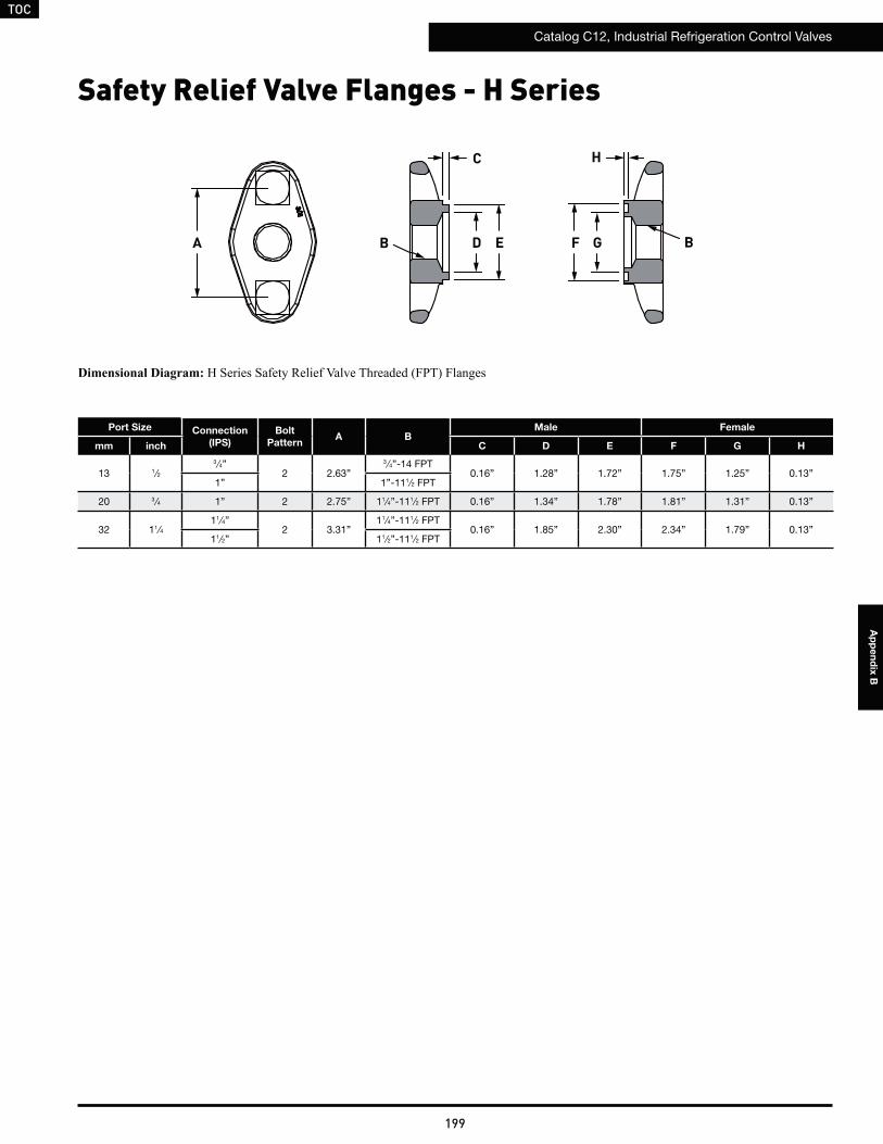
TOC
Catalog C12, Industrial Refrigeration Control Valves
199
Ap
pe
nd
ix B
Safety Relief Valve Flanges - H Series
Port Size Connection
(IPS)
Bolt
PatternA B
Male Female
mm inch C D E F G H
13 1⁄23 ⁄4”
2 2.63”3 ⁄4”-14 FPT
0.16” 1.28” 1.72” 1.75” 1.25” 0.13”1” 1”-111⁄2 FPT
20 3 ⁄4 1” 2 2.75” 11⁄4”-111⁄2 FPT 0.16” 1.34” 1.78” 1.81” 1.31” 0.13”
32 11⁄411⁄4”
2 3.31”11⁄4”-111⁄2 FPT
0.16” 1.85” 2.30” 2.34” 1.79” 0.13”11⁄2” 11⁄2”-111⁄2 FPT
A DB E F G
HC
B
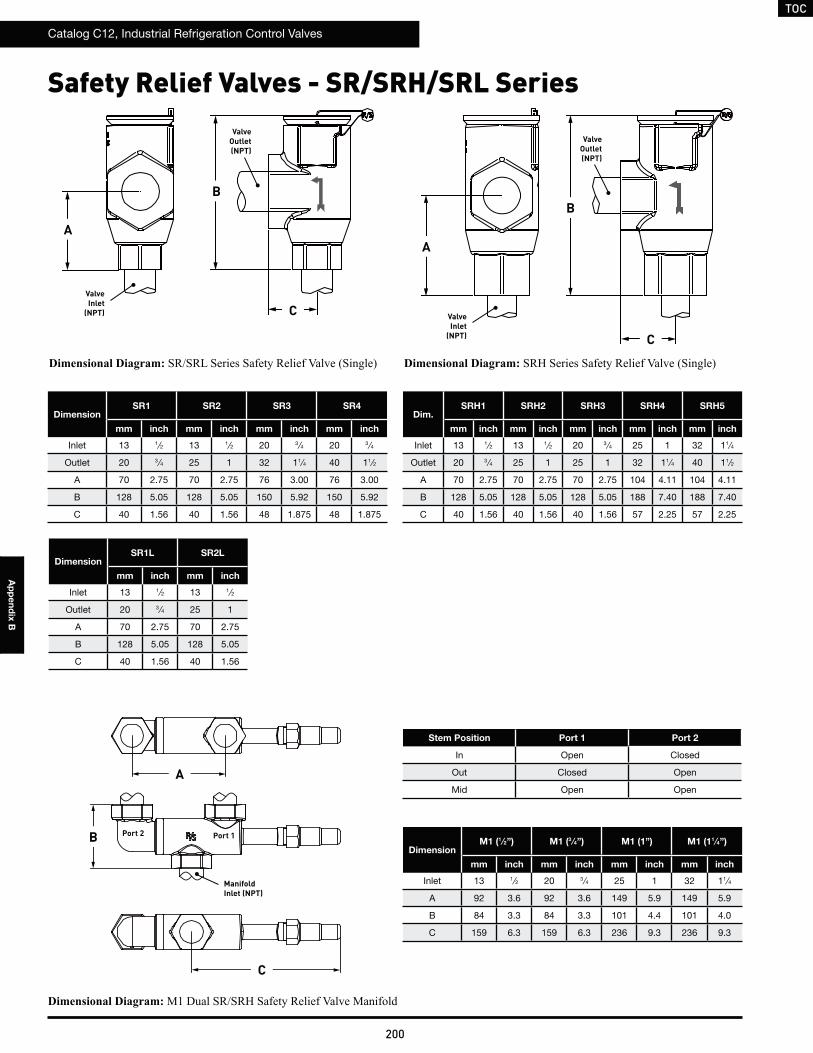
TOC
Catalog C12, Industrial Refrigeration Control Valves
200
Ap
pe
nd
ix B
Safety Relief Valves - SR/SRH/SRL Series
DimensionSR1 SR2 SR3 SR4
mm inch mm inch mm inch mm inch
Inlet 13 1⁄2 13 1⁄2 20 3 ⁄4 20 3 ⁄4
Outlet 20 3 ⁄4 25 1 32 11⁄4 40 11⁄2
A 70 2.75 70 2.75 76 3.00 76 3.00
B 128 5.05 128 5.05 150 5.92 150 5.92
C 40 1.56 40 1.56 48 1.875 48 1.875
Stem Position Port 1 Port 2
In Open Closed
Out Closed Open
Mid Open Open
DimensionSR1L SR2L
mm inch mm inch
Inlet 13 1⁄2 13 1⁄2
Outlet 20 3 ⁄4 25 1
A 70 2.75 70 2.75
B 128 5.05 128 5.05
C 40 1.56 40 1.56
Dim.SRH1 SRH2 SRH3 SRH4 SRH5
mm inch mm inch mm inch mm inch mm inch
Inlet 13 1⁄2 13 1⁄2 20 3 ⁄4 25 1 32 11⁄4
Outlet 20 3 ⁄4 25 1 25 1 32 11⁄4 40 11⁄2
A 70 2.75 70 2.75 70 2.75 104 4.11 104 4.11
B 128 5.05 128 5.05 128 5.05 188 7.40 188 7.40
C 40 1.56 40 1.56 40 1.56 57 2.25 57 2.25
DimensionM1 (1 ⁄2”) M1 (3 ⁄4”) M1 (1”) M1 (11 ⁄4”)
mm inch mm inch mm inch mm inch
Inlet 13 1⁄2 20 3 ⁄4 25 1 32 11⁄4
A 92 3.6 92 3.6 149 5.9 149 5.9
B 84 3.3 84 3.3 101 4.4 101 4.0
C 159 6.3 159 6.3 236 9.3 236 9.3
A
B
CValve Inlet
(NPT)
Valve Outlet(NPT)
A
B
C
Valve Inlet
(NPT)
Valve Outlet(NPT)
A
B
C
ManifoldInlet (NPT)
Port 1Port 2
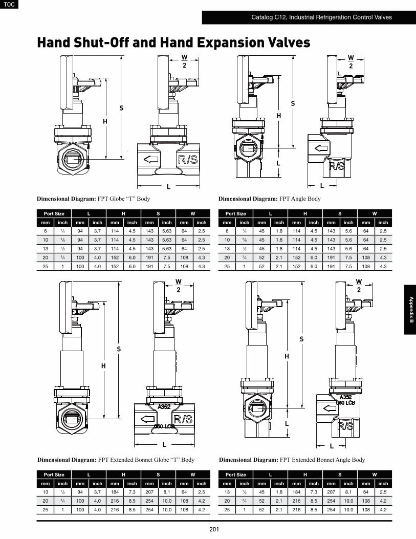
TOC
Catalog C12, Industrial Refrigeration Control Valves
201
Ap
pe
nd
ix B
Hand Shut-Off and Hand Expansion Valves
FPT Angle Body
Port Size L H S W
mm inch mm inch mm inch mm inch mm inch
6 1⁄4 94 3.7 114 4.5 143 5.63 64 2.5
10 3 ⁄8 94 3.7 114 4.5 143 5.63 64 2.5
13 1⁄2 94 3.7 114 4.5 143 5.63 64 2.5
20 3 ⁄4 100 4.0 152 6.0 191 7.5 108 4.3
25 1 100 4.0 152 6.0 191 7.5 108 4.3
Port Size L H S W
mm inch mm inch mm inch mm inch mm inch
6 1⁄4 45 1.8 114 4.5 143 5.6 64 2.5
10 3 ⁄8 45 1.8 114 4.5 143 5.6 64 2.5
13 1⁄2 45 1.8 114 4.5 143 5.6 64 2.5
20 3 ⁄4 52 2.1 152 6.0 191 7.5 108 4.3
25 1 52 2.1 152 6.0 191 7.5 108 4.3
Port Size L H S W
mm inch mm inch mm inch mm inch mm inch
13 1⁄2 94 3.7 184 7.3 207 8.1 64 2.5
20 3 ⁄4 100 4.0 216 8.5 254 10.0 108 4.2
25 1 100 4.0 216 8.5 254 10.0 108 4.2
Port Size L H S W
mm inch mm inch mm inch mm inch mm inch
13 1⁄2 45 1.8 184 7.3 207 8.1 64 2.5
20 3 ⁄4 52 2.1 216 8.5 254 10.0 108 4.2
25 1 52 2.1 216 8.5 254 10.0 108 4.2
S
H
L L
LL
S
HH
S
S
H
L
L
W2
W2
W2
W2
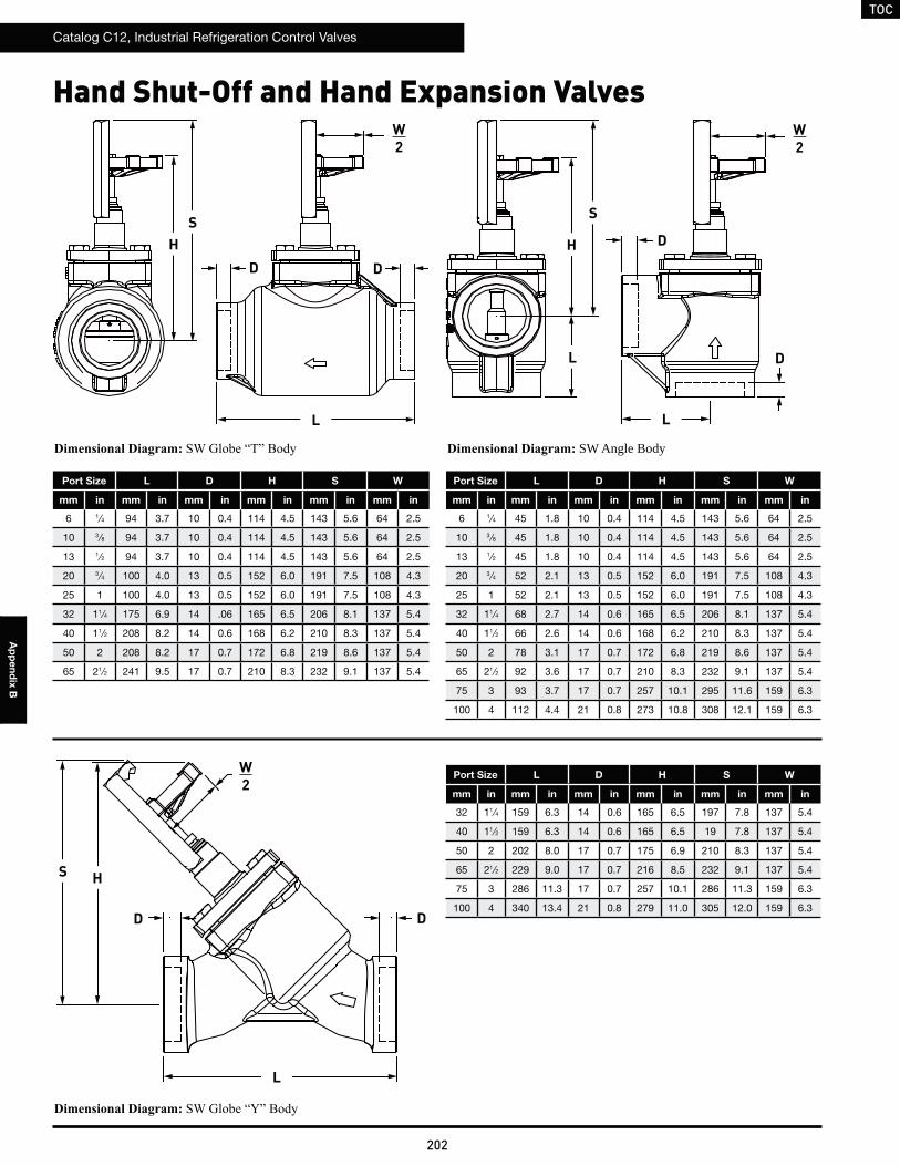
TOC
Catalog C12, Industrial Refrigeration Control Valves
202
Ap
pe
nd
ix B
Hand Shut-Off and Hand Expansion Valves
SW Angle Body
Port Size L D H S W
mm in mm in mm in mm in mm in mm in
6 1⁄4 94 3.7 10 0.4 114 4.5 143 5.6 64 2.5
10 3 ⁄8 94 3.7 10 0.4 114 4.5 143 5.6 64 2.5
13 1⁄2 94 3.7 10 0.4 114 4.5 143 5.6 64 2.5
20 3 ⁄4 100 4.0 13 0.5 152 6.0 191 7.5 108 4.3
25 1 100 4.0 13 0.5 152 6.0 191 7.5 108 4.3
32 11⁄4 175 6.9 14 .06 165 6.5 206 8.1 137 5.4
40 11⁄2 208 8.2 14 0.6 168 6.2 210 8.3 137 5.4
50 2 208 8.2 17 0.7 172 6.8 219 8.6 137 5.4
65 21⁄2 241 9.5 17 0.7 210 8.3 232 9.1 137 5.4
Port Size L D H S W
mm in mm in mm in mm in mm in mm in
6 1⁄4 45 1.8 10 0.4 114 4.5 143 5.6 64 2.5
10 3 ⁄8 45 1.8 10 0.4 114 4.5 143 5.6 64 2.5
13 1⁄2 45 1.8 10 0.4 114 4.5 143 5.6 64 2.5
20 3 ⁄4 52 2.1 13 0.5 152 6.0 191 7.5 108 4.3
25 1 52 2.1 13 0.5 152 6.0 191 7.5 108 4.3
32 11⁄4 68 2.7 14 0.6 165 6.5 206 8.1 137 5.4
40 11⁄2 66 2.6 14 0.6 168 6.2 210 8.3 137 5.4
50 2 78 3.1 17 0.7 172 6.8 219 8.6 137 5.4
65 21⁄2 92 3.6 17 0.7 210 8.3 232 9.1 137 5.4
75 3 93 3.7 17 0.7 257 10.1 295 11.6 159 6.3
100 4 112 4.4 21 0.8 273 10.8 308 12.1 159 6.3
Port Size L D H S W
mm in mm in mm in mm in mm in mm in
32 11⁄4 159 6.3 14 0.6 165 6.5 197 7.8 137 5.4
40 11⁄2 159 6.3 14 0.6 165 6.5 19 7.8 137 5.4
50 2 202 8.0 17 0.7 175 6.9 210 8.3 137 5.4
65 21⁄2 229 9.0 17 0.7 216 8.5 232 9.1 137 5.4
75 3 286 11.3 17 0.7 257 10.1 286 11.3 159 6.3
100 4 340 13.4 21 0.8 279 11.0 305 12.0 159 6.3
SH
L
W2
W2
D D
D
D
DD
W2
S
S
H
H
L
L
L
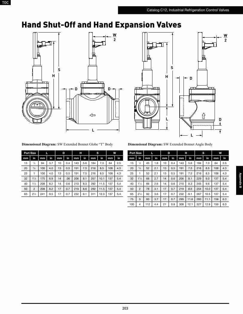
TOC
Catalog C12, Industrial Refrigeration Control Valves
203
Ap
pe
nd
ix B
Hand Shut-Off and Hand Expansion Valves
Port Size L D H S W
mm in mm in mm in mm in mm in mm in
13 1⁄2 94 3.7 10 0.4 143 5.6 184 7.3 64 2.5
20 3 ⁄4 100 4.0 13 0.5 191 7.5 216 8.5 108 4.3
25 1 100 4.0 13 0.5 191 7.5 216 8.5 108 4.3
32 11⁄4 175 6.9 14 .06 206 8.1 257 10.1 137 5.4
40 11⁄2 208 8.2 14 0.6 210 8.3 292 11.5 137 5.4
50 2 208 8.2 17 0.7 219 8.6 292 11.5 137 5.4
65 21⁄2 241 9.5 17 0.7 232 9.1 311 12.3 137 5.4
Port Size L D H S W
mm in mm in mm in mm in mm in mm in
13 1⁄2 45 1.8 10 0.4 143 5.6 184 7.3 64 2.5
20 3 ⁄4 52 2.1 13 0.5 191 7.5 216 8.5 108 4.3
25 1 52 2.1 13 0.5 191 7.5 216 8.5 108 4.3
32 11⁄4 68 2.7 14 0.6 206 8.1 229 9.0 137 5.4
40 11⁄2 66 2.6 14 0.6 210 8.3 245 9.6 137 5.4
50 2 78 3.1 17 0.7 219 8.6 254 10.0 137 5.4
65 21⁄2 92 3.6 17 0.7 232 9.1 267 10.5 137 5.4
75 3 93 3.7 17 0.7 295 11.6 283 11.1 159 6.3
100 4 112 4.4 21 0.8 308 12.1 327 12.9 159 6.3
SH
L
W2
D D
W2
D
D
S
H
L
L
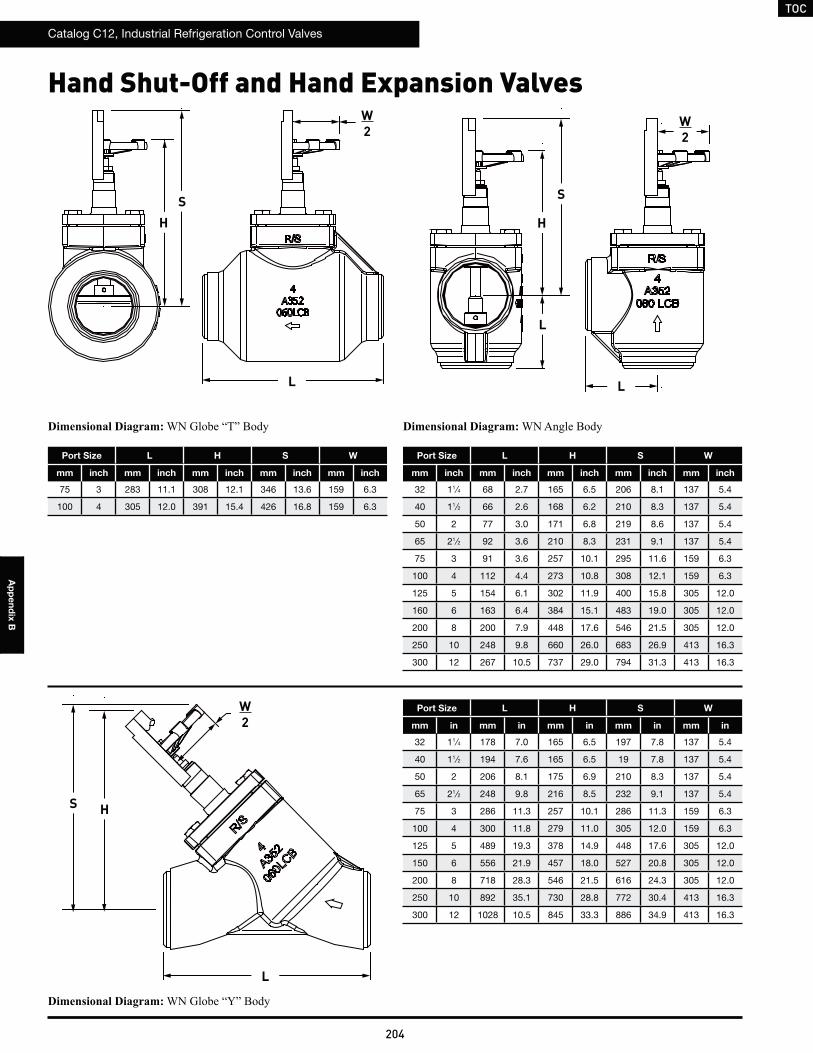
TOC
Catalog C12, Industrial Refrigeration Control Valves
204
Ap
pe
nd
ix B
Port Size L H S W
mm inch mm inch mm inch mm inch mm inch
75 3 283 11.1 308 12.1 346 13.6 159 6.3
100 4 305 12.0 391 15.4 426 16.8 159 6.3
Port Size L H S W
mm inch mm inch mm inch mm inch mm inch
32 11⁄4 68 2.7 165 6.5 206 8.1 137 5.4
40 11⁄2 66 2.6 168 6.2 210 8.3 137 5.4
50 2 77 3.0 171 6.8 219 8.6 137 5.4
65 21⁄2 92 3.6 210 8.3 231 9.1 137 5.4
75 3 91 3.6 257 10.1 295 11.6 159 6.3
100 4 112 4.4 273 10.8 308 12.1 159 6.3
125 5 154 6.1 302 11.9 400 15.8 305 12.0
160 6 163 6.4 384 15.1 483 19.0 305 12.0
200 8 200 7.9 448 17.6 546 21.5 305 12.0
250 10 248 9.8 660 26.0 683 26.9 413 16.3
300 12 267 10.5 737 29.0 794 31.3 413 16.3
Port Size L H S W
mm in mm in mm in mm in mm in
32 11⁄4 178 7.0 165 6.5 197 7.8 137 5.4
40 11⁄2 194 7.6 165 6.5 19 7.8 137 5.4
50 2 206 8.1 175 6.9 210 8.3 137 5.4
65 21⁄2 248 9.8 216 8.5 232 9.1 137 5.4
75 3 286 11.3 257 10.1 286 11.3 159 6.3
100 4 300 11.8 279 11.0 305 12.0 159 6.3
125 5 489 19.3 378 14.9 448 17.6 305 12.0
150 6 556 21.9 457 18.0 527 20.8 305 12.0
200 8 718 28.3 546 21.5 616 24.3 305 12.0
250 10 892 35.1 730 28.8 772 30.4 413 16.3
300 12 1028 10.5 845 33.3 886 34.9 413 16.3
Hand Shut-Off and Hand Expansion Valves
SH
L
W2
W2
W2
S
S
H
H
L
L
L
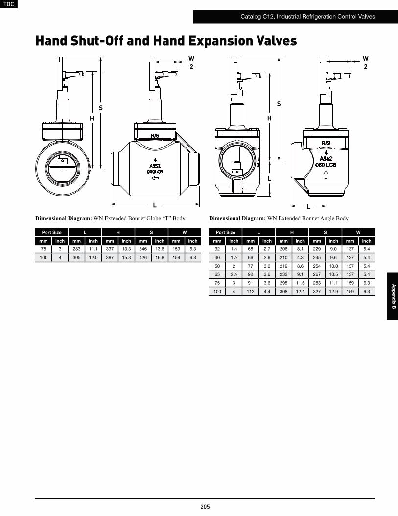
TOC
Catalog C12, Industrial Refrigeration Control Valves
205
Ap
pe
nd
ix B
Port Size L H S W
mm inch mm inch mm inch mm inch mm inch
75 3 283 11.1 337 13.3 346 13.6 159 6.3
100 4 305 12.0 387 15.3 426 16.8 159 6.3
Port Size L H S W
mm inch mm inch mm inch mm inch mm inch
32 11⁄4 68 2.7 206 8.1 229 9.0 137 5.4
40 11⁄2 66 2.6 210 4.3 245 9.6 137 5.4
50 2 77 3.0 219 8.6 254 10.0 137 5.4
65 21⁄2 92 3.6 232 9.1 267 10.5 137 5.4
75 3 91 3.6 295 11.6 283 11.1 159 6.3
100 4 112 4.4 308 12.1 327 12.9 159 6.3
Hand Shut-Off and Hand Expansion Valves
SH
L
W2
W2
S
H
L
L
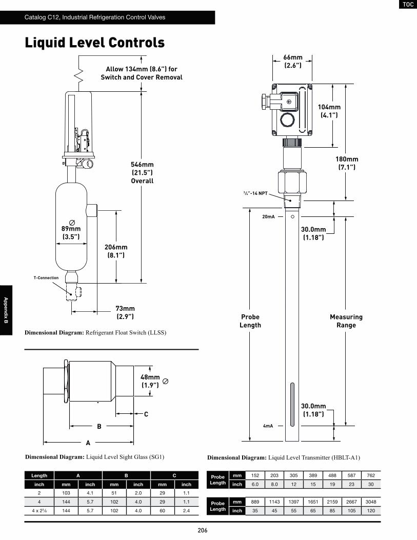
TOC
Catalog C12, Industrial Refrigeration Control Valves
206
Ap
pe
nd
ix B
Liquid Level Controls
T-Connection
Length A B C
inch mm inch mm inch mm inch
2 103 4.1 51 2.0 29 1.1
4 144 5.7 102 4.0 29 1.1
4 x 23 ⁄8 144 5.7 102 4.0 60 2.4
Probe
Length
mm 152 203 305 389 488 587 762
inch 6.0 8.0 12 15 19 23 30
Probe
Length
mm 889 1143 1397 1651 2159 2667 3048
inch 35 45 55 65 85 105 120
546mm(21.5”)Overall
206mm(8.1”)
73mm(2.9”)
89mm(3.5”)
Allow 134mm (8.6”) for Switch and Cover Removal
B
48mm(1.9”)
A
C
30.0mm(1.18”)
104mm(4.1”)
180mm(7.1”)
66mm(2.6”)
30.0mm(1.18”)
ProbeLength
MeasuringRange
3 ⁄4”-14 NPT
20mA
4mA
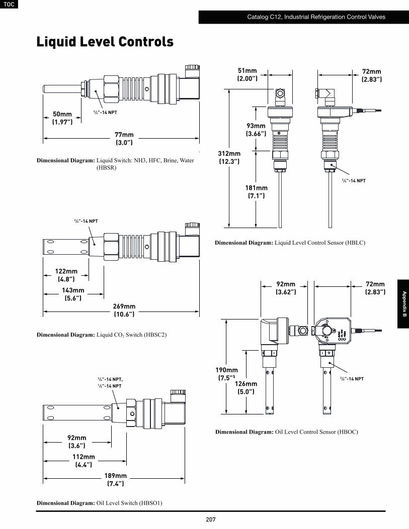
TOC
Catalog C12, Industrial Refrigeration Control Valves
207
Ap
pe
nd
ix B
Liquid Level Controls
2
3 ⁄4”-14 NPT
3 ⁄4”-14 NPT,1 ⁄2”-14 NPT
3 ⁄4”-14 NPT50mm(1.97”)
77mm(3.0”)
122mm(4.8”)
269mm(10.6”)
143mm(5.6”)
92mm(3.6”)
189mm(7.4”)
112mm(4.4”)
181mm(7.1”)
312mm(12.3”)
93mm(3.66”)
72mm(2.83”)
51mm(2.00”)
3 ⁄4”-14 NPT
72mm(2.83”)
92mm(3.62”)
190mm(7.5”)
126mm(5.0”)
3 ⁄4”-14 NPT
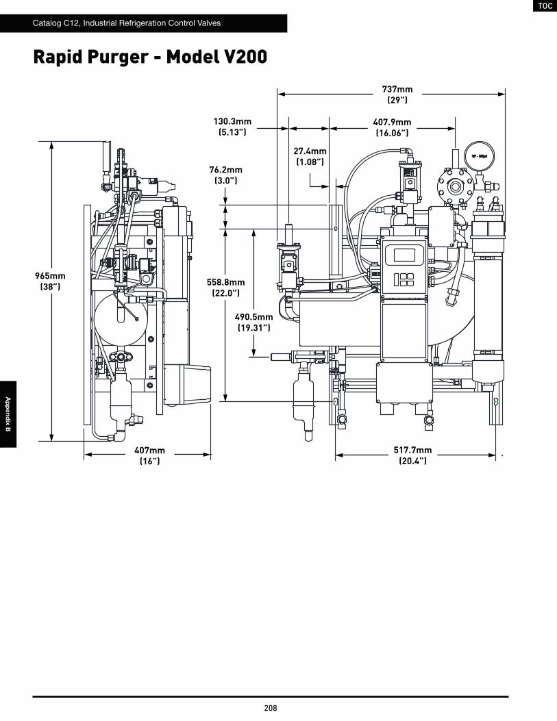
TOC
Catalog C12, Industrial Refrigeration Control Valves
208
Ap
pe
nd
ix B
Rapid Purger - Model V200
965mm(38”)
407mm(16”)
558.8mm(22.0”)
737mm(29”)
517.7mm(20.4”)
407.9mm(16.06”)
490.5mm(19.31”)
27.4mm(1.08”)
76.2mm(3.0”)
130.3mm(5.13”)
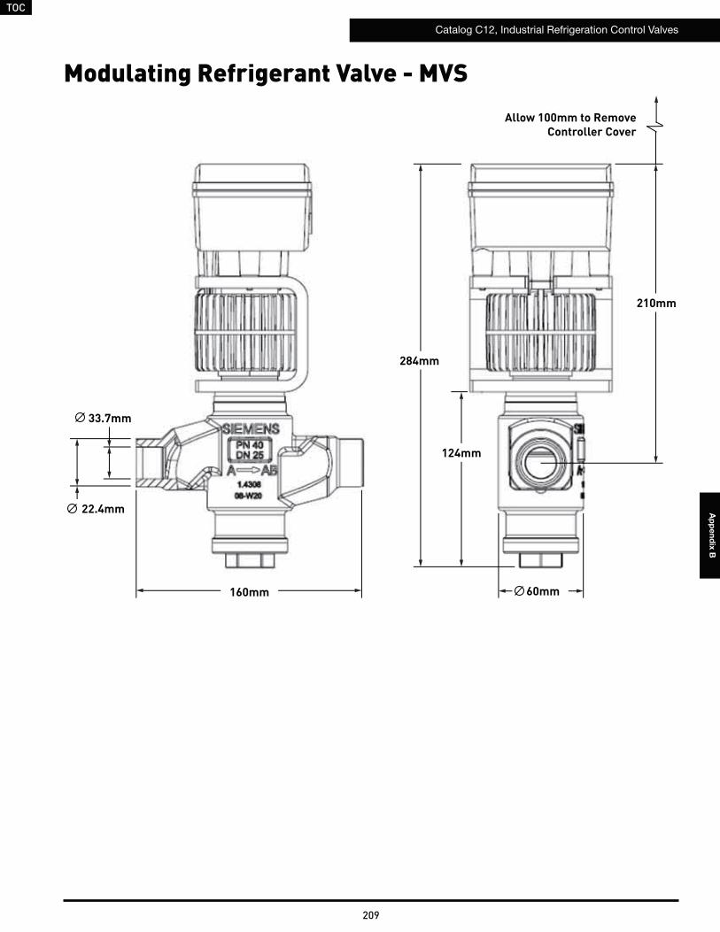
TOC
Catalog C12, Industrial Refrigeration Control Valves
209
Ap
pe
nd
ix B
Modulating Refrigerant Valve - MVS
160mm 60mm
124mm
284mm
210mm
33.7mm
22.4mm
Allow 100mm to Remove Controller Cover
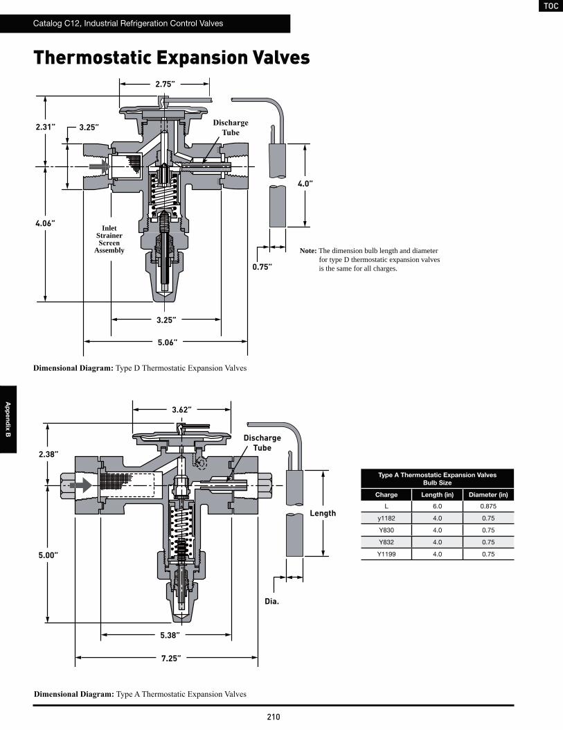
TOC
Catalog C12, Industrial Refrigeration Control Valves
210
Ap
pe
nd
ix B
3.25”
2.75”
2.31”
4.06” InletStrainer
Assembly
3.25”
5.06”
4.0”
0.75”
Thermostatic Expansion Valves
2.38”
3.62”
5.00”
5.38”
Discharge Tube
Dia.
Length
7.25”
Type A Thermostatic Expansion Valves
Bulb Size
Charge Length (in) Diameter (in)
L 6.0 0.875
y1182 4.0 0.75
Y830 4.0 0.75
Y832 4.0 0.75
Y1199 4.0 0.75
Note: The dimension bulb length and diameter for type D thermostatic expansion valves is the same for all charges.
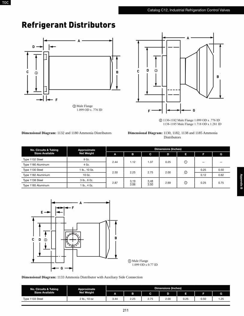
TOC
Catalog C12, Industrial Refrigeration Control Valves
211
Ap
pe
nd
ix B
Male Flange 1
2
C
D
A
B
F
12C D
A
B
F G
Refrigerant Distributors
1132 and 1180 Ammonia Distributors 1130, 1182, 1138 and 1185 Ammonia Distributors
No. Circuits & Tubing
Sizes Available
Approximate
Net Weight
Dimensions (Inches)
A B C D E F G
Type 1132 Steel 9 0z.2.44 1.12 1.37 0.25 1 — —
Type 1180 Aluminum 4 0z.
Type 1130 Steel 1 lb., 10 0z.2.50 2.25 2.75 2.00 2
0.25 0.50
Type 1182 Aluminium 10 0z. 0.12 0.62
Type 1138 Steel 3 lb., 6 0z.2.87
3.193.06
3.483.50
2.69 2 0.25 0.75Type 1185 Aluminum 1 lb., 4 0z.
No. Circuits & Tubing
Sizes Available
Approximate
Net Weight
Dimensions (Inches)
A B C D E F G
Type 1133 Steel 2 lb., 10 oz 3.44 2.25 2.75 2.00 0.25 0.50 1.25
1C D
A
B
F
Male Flange1
G
E
1133 Ammonia Distributor with Auxiliary Side Connection
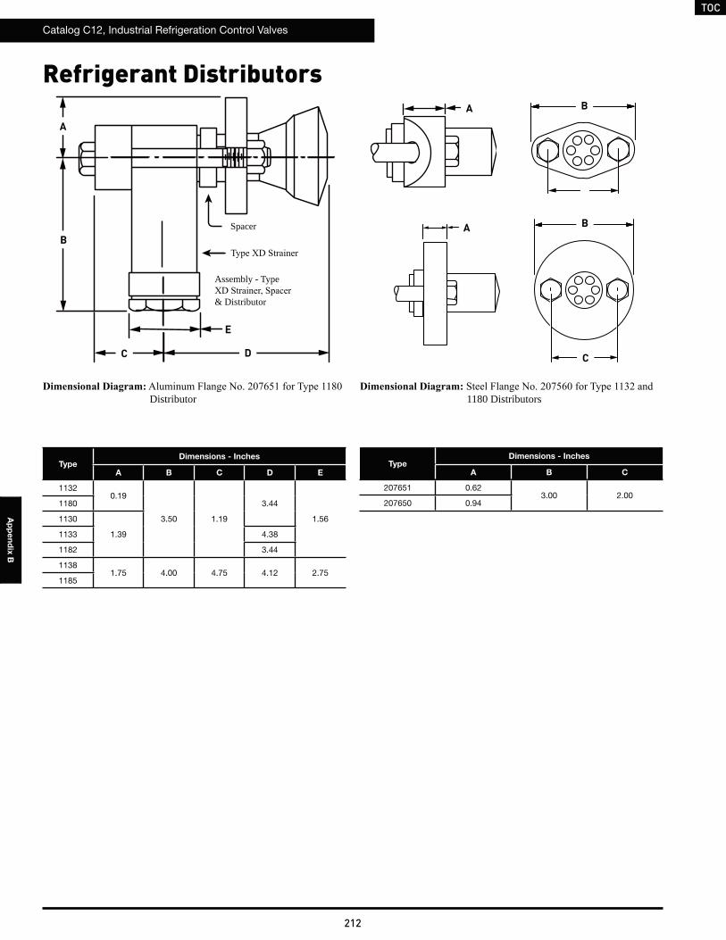
TOC
Catalog C12, Industrial Refrigeration Control Valves
212
Ap
pe
nd
ix B
TypeDimensions - Inches
A B C D E
11320.19
3.50 1.19
3.44
1.56
1180
1130
1.391133 4.38
1182 3.44
11381.75 4.00 4.75 4.12 2.75
1185
Spacer
Assembly - Type
& Distributor
C D
A
B
E
A B
A
C
B
Refrigerant Distributors
TypeDimensions - Inches
A B C
207651 0.623.00 2.00
207650 0.94
Distributor 1180 Distributors
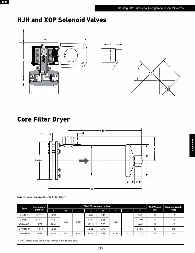
TOC
Catalog C12, Industrial Refrigeration Control Valves
213
Ap
pe
nd
ix B
TypeConnections
(Inches)
Shell Dimensions Inches Net Weight
(lbs)
Shipping Weight
(lbs)A B C D E F G *P
C-484-P 1⁄2 FPT 9.08
6.00 5.00
5.85 3.41
4.75 —
7.50 10 12
C-966-P 3 ⁄4 FPT 14.67 11.44 3.48 13.00 14 16
C-1448-P 1 FPT 20.42 17.19 3.66 18.62 17 20
C-19212-P 11⁄2 FPT 25.85 22.62 3.76 24.25 20 23
C-40016-P 2 FPT 34.44 7.50 6.25 30.38 4.38 6.00 — 32.12 46 51
Diameter
C
D
A
B
G*P
E
G
Core Filter Dryer
Core Filter Dryer
* “P” Dimension is the pull space required to change core.
HJH and XOP Solenoid Valves
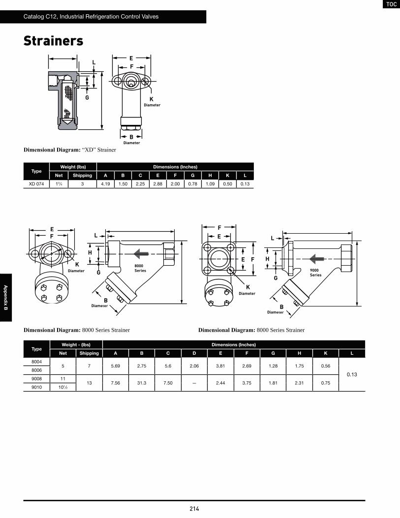
TOC
Catalog C12, Industrial Refrigeration Control Valves
214
Ap
pe
nd
ix B
Strainers
TypeWeight (lbs) Dimensions (Inches)
Net Shipping A B C E F G H K L
XD 074 13 ⁄4 3 4.19 1.50 2.25 2.88 2.00 0.78 1.09 0.50 0.13
TypeWeight - (lbs) Dimensions (Inches)
Net Shipping A B C D E F G H K L
80045 7 5.69 2.75 5.6 2.06 3.81 2.69 1.28 1.75 0.56
0.138006
9008 1113 7.56 31.3 7.50 — 2.44 3.75 1.81 2.31 0.75
9010 101⁄2
DiameterB
EF
G KDiameter
L
DiameterB
H
G
LEF L
G
H8000Series 9000
Series
DiameterB
DiameterK
DiameterK
F
F
E
E
8000 Series Strainer 8000 Series Strainer
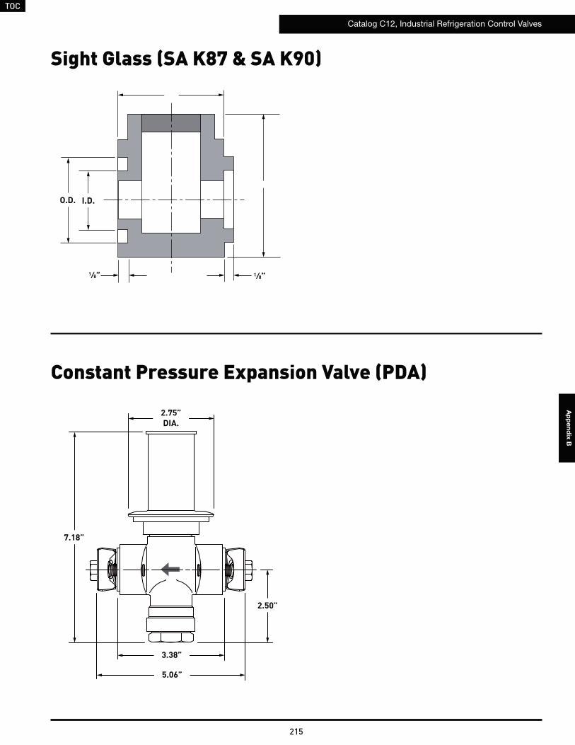
TOC
Catalog C12, Industrial Refrigeration Control Valves
215
Ap
pe
nd
ix B
Sight Glass (SA K87 & SA K90)
O.D. I.D.
1⁄8”1⁄8”
Constant Pressure Expansion Valve (PDA)
2.50”
3.38”
5.06”
2.75”DIA.
7.18”
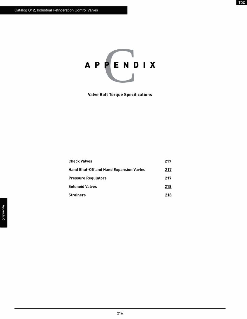
TOC
Catalog C12, Industrial Refrigeration Control Valves
216
Ap
pe
nd
ix C
Valve Bolt Torque Specifications
CA P P E N D I X
Check Valves 217
Hand Shut-Off and Hand Expansion Vavles 217
Pressure Regulators 217
Solenoid Valves 218
Strainers 218
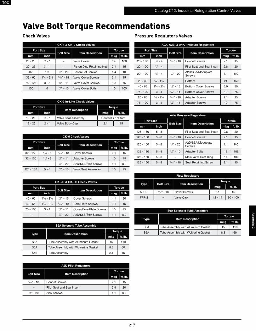
TOC
Catalog C12, Industrial Refrigeration Control Valves
217
Ap
pe
nd
ix C
Valve Bolt Torque Recommendations
A2A, A2B, & A4A Pressure Regulators
Port SizeBolt Size Item Description
Torque
mm inch mkg ft. lb.
20 - 100 3 ⁄4 - 4 5 ⁄16” - 18 Bonnet Screws 2.1 15
20 - 100 3 ⁄4 - 4 – Pilot Seat and Seal Insert 2.8 20
20 - 100 3 ⁄4 - 4 1⁄4” - 20A2D/S6A/Moduplate Screws
1.1 8.0
20 - 32 3 ⁄4 - 11⁄4 – Bottom 21 150
40 - 65 15 ⁄8 - 21⁄2 1 ⁄2” - 13 Bottom Cover Screws 6.9 50
75 - 100 3 - 4 5 ⁄8” - 11 Bottom Cover Screws 10 75
20 - 65 3 ⁄4 - 21⁄2 5 ⁄16” - 18 Adapter Screws 2.1 15
75 - 100 3 - 4 5 ⁄8” - 11 Adapter Screws 10 75
A4W Pressure Regulators
Port SizeBolt Size Item Description
Torque
mm inch mkg ft. lb.
125 - 150 5 - 8 – Pilot Seat and Seal Insert 2.8 20
125 - 150 5 - 8 5 ⁄16” - 18 Bonnet Screws 2.1 15
125 - 150 5 - 8 1⁄4” - 20A2D/S6A/Moduplate Screws
1.1 8.0
125 - 150 5 - 8 3 ⁄4” - 10 Adapter Bolts 15 105
125 - 150 5 - 8 – Main Valve Seat Ring 14 100
125 - 150 5 - 8 5 ⁄16” - 18 Seat Retaining Screw 2.1 15
Flow Regulators
Type Bolt Size Item DescriptionTorque
mkg ft. lb.
AFR-3 5 ⁄16” - 18 Cover Screws 2.1 15
FFR-2 – Valve Cap 12 - 14 90 - 100
Pressure Regulators Valves
CK-1 & CK-2 Check Valves
Port SizeBolt Size Item Description
Torque
mm inch mkg ft. lb.
20 - 25 3 ⁄4 - 1 – Valve Cover 14 100
20 - 25 3 ⁄4 - 1 – Piston Disc Retaining Nut 2.1 15
32 11⁄4 1 ⁄4” - 20 Piston Set Screws 1.4 10
32 - 65 11⁄4 - 21⁄2 5 ⁄16” - 18 Valve Cover Screws 2.1 15
75 - 125 3 - 5 5 ⁄8” - 11 Valve Cover Screws 10 75
150 6 3 ⁄4” - 10 Valve Cover Bolts 15 105
CK-3 In-Line Check Valves
Port SizeItem Description
Torque
mm inch mkg ft. lb.
13 - 25 1⁄2 - 1 Valve Seat Assembly Contact + 1/4 turn
13 - 25 1⁄2 - 1 Valve Body Cap 2.1 15
CK-5 Check Valves
Port SizeBolt Size Item Description
Torque
mm inch mkg ft. lb.
32 - 150 11⁄4 - 6 5 ⁄16” - 18 Cover Screws 2.1 15
32 - 150 11⁄4 - 6 5 ⁄8” - 11 Adapter Screws 10 75
– – 1⁄4” - 20 A2D/S6B/S6A Screws 1.1 8.0
125 - 150 5 - 6 3 ⁄4” - 10 Valve Seat Assembly 10 75
Check Valves
S6A Solenoid Tube Assembly
Type Item DescriptionTorque
mkg ft. lb.
S6A Tube Assembly with Aluminum Gasket 15 110
S6A Tube Assembly with Wolverine Gasket 8.3 60
S6A Solenoid Tube Assembly
Type Item DescriptionTorque
mkg ft. lb.
S6A Tube Assembly with Aluminum Gasket 15 110
S6A Tube Assembly with Wolverine Gasket 8.3 60
S6B Tube Assembly 2.1 15
CK-2D & CK-6D Check Valves
Port SizeBolt Size Item Description
Torque
mm inch mkg ft. lb.
40 - 65 15 ⁄8 - 21⁄2 3 ⁄8” - 16 Cover Screws 4.1 30
40 - 65 15 ⁄8 - 21⁄2 5 ⁄16” - 18 Bore Plate Screws 2.1 15
75 - 100 3 - 4 5 ⁄8” - 11 Cover/Bore Plate Screws 10 75
– – 1⁄4” - 20 A2D/S6B/S6A Screws 1.1 8.0
A2D Pilot Regulators
Bolt Size Item DescriptionTorque
mkg ft. lb.
5 ⁄16” - 18 Bonnet Screws 2.1 15
– Pilot Seat and Seal Insert 2.8 20
1⁄4” - 20 A2D Screws 1.1 8.0
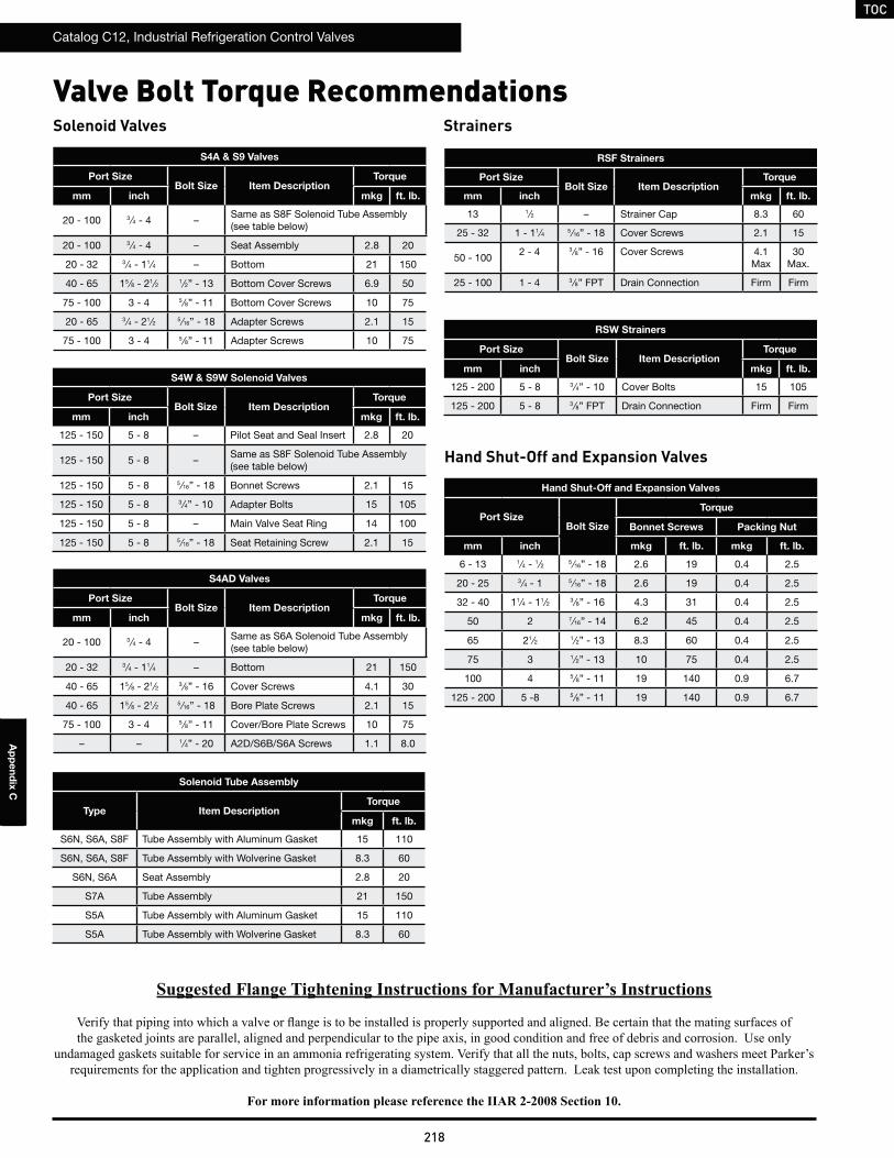
TOC
Catalog C12, Industrial Refrigeration Control Valves
218
Ap
pe
nd
ix C
Valve Bolt Torque Recommendations
S4A & S9 Valves
Port SizeBolt Size Item Description
Torque
mm inch mkg ft. lb.
20 - 100 3 ⁄4 - 4 –Same as S8F Solenoid Tube Assembly (see table below)
20 - 100 3 ⁄4 - 4 – Seat Assembly 2.8 20
20 - 32 3 ⁄4 - 11⁄4 – Bottom 21 150
40 - 65 15 ⁄8 - 21⁄2 1 ⁄2” - 13 Bottom Cover Screws 6.9 50
75 - 100 3 - 4 5 ⁄8” - 11 Bottom Cover Screws 10 75
20 - 65 3 ⁄4 - 21⁄2 5 ⁄16” - 18 Adapter Screws 2.1 15
75 - 100 3 - 4 5 ⁄8” - 11 Adapter Screws 10 75
S4W & S9W Solenoid Valves
Port SizeBolt Size Item Description
Torque
mm inch mkg ft. lb.
125 - 150 5 - 8 – Pilot Seat and Seal Insert 2.8 20
125 - 150 5 - 8 –Same as S8F Solenoid Tube Assembly (see table below)
125 - 150 5 - 8 5 ⁄16” - 18 Bonnet Screws 2.1 15
125 - 150 5 - 8 3 ⁄4” - 10 Adapter Bolts 15 105
125 - 150 5 - 8 – Main Valve Seat Ring 14 100
125 - 150 5 - 8 5 ⁄16” - 18 Seat Retaining Screw 2.1 15
Solenoid Tube Assembly
Type Item DescriptionTorque
mkg ft. lb.
S6N, S6A, S8F Tube Assembly with Aluminum Gasket 15 110
S6N, S6A, S8F Tube Assembly with Wolverine Gasket 8.3 60
S6N, S6A Seat Assembly 2.8 20
S7A Tube Assembly 21 150
S5A Tube Assembly with Aluminum Gasket 15 110
S5A Tube Assembly with Wolverine Gasket 8.3 60
Solenoid Valves
RSF Strainers
Port SizeBolt Size Item Description
Torque
mm inch mkg ft. lb.
13 1⁄2 – Strainer Cap 8.3 60
25 - 32 1 - 11⁄4 5 ⁄16” - 18 Cover Screws 2.1 15
50 - 1002 - 4 3 ⁄8” - 16 Cover Screws 4.1
Max30
Max.
25 - 100 1 - 4 3 ⁄8” FPT Drain Connection Firm Firm
RSW Strainers
Port SizeBolt Size Item Description
Torque
mm inch mkg ft. lb.
125 - 200 5 - 8 3 ⁄4” - 10 Cover Bolts 15 105
125 - 200 5 - 8 3 ⁄8” FPT Drain Connection Firm Firm
Strainers
Hand Shut-Off and Expansion Valves
Port SizeBolt Size
Torque
Bonnet Screws Packing Nut
mm inch mkg ft. lb. mkg ft. lb.
6 - 13 1⁄4 - 1 ⁄2 5 ⁄16” - 18 2.6 19 0.4 2.5
20 - 25 3 ⁄4 - 1 5 ⁄16” - 18 2.6 19 0.4 2.5
32 - 40 11⁄4 - 11⁄2 3 ⁄8” - 16 4.3 31 0.4 2.5
50 2 7⁄16” - 14 6.2 45 0.4 2.5
65 21⁄2 1 ⁄2” - 13 8.3 60 0.4 2.5
75 3 1⁄2” - 13 10 75 0.4 2.5
100 4 5 ⁄8” - 11 19 140 0.9 6.7
125 - 200 5 -8 5 ⁄8” - 11 19 140 0.9 6.7
Hand Shut-Off and Expansion Valves
S4AD Valves
Port SizeBolt Size Item Description
Torque
mm inch mkg ft. lb.
20 - 100 3 ⁄4 - 4 –Same as S6A Solenoid Tube Assembly (see table below)
20 - 32 3 ⁄4 - 11⁄4 – Bottom 21 150
40 - 65 15 ⁄8 - 21⁄2 3 ⁄8” - 16 Cover Screws 4.1 30
40 - 65 15 ⁄8 - 21⁄2 5 ⁄16” - 18 Bore Plate Screws 2.1 15
75 - 100 3 - 4 5 ⁄8” - 11 Cover/Bore Plate Screws 10 75
– – 1⁄4” - 20 A2D/S6B/S6A Screws 1.1 8.0
TOC
Catalog C12, Industrial Refrigeration Control Valves
219
Ap
pe
nd
ix D
Valve Classification: Pressure Equipment Directive (PED)
DA P P E N D I X
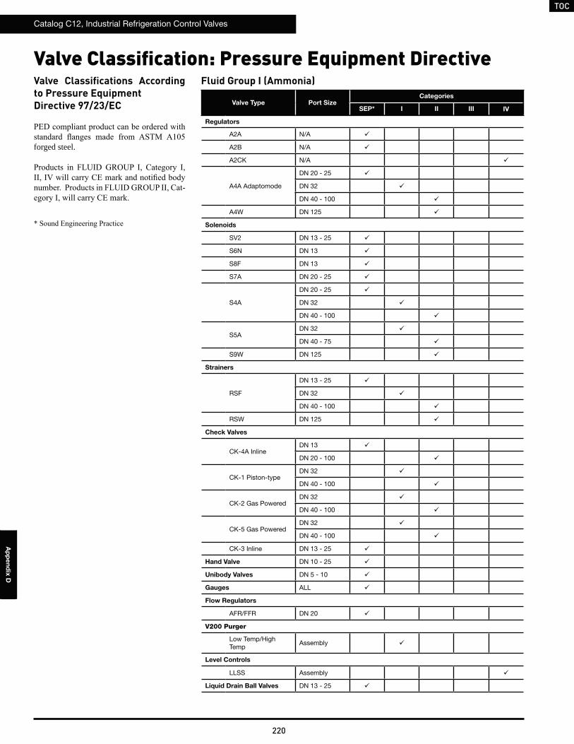
TOC
Catalog C12, Industrial Refrigeration Control Valves
220
Ap
pe
nd
ix D
Valve Classifications According to Pressure EquipmentDirective 97/23/EC
forged steel.
-
Fluid Group I (Ammonia)
Valve Type Port SizeCategories
SEP* I II III IV
Regulators
A2A N/A
A2B N/A
A2CK N/A
A4A Adaptomode
DN 20 - 25
DN 32
DN 40 - 100
A4W DN 125
Solenoids
SV2 DN 13 - 25
S6N DN 13
S8F DN 13
S7A DN 20 - 25
S4A
DN 20 - 25
DN 32
DN 40 - 100
S5ADN 32
DN 40 - 75
S9W DN 125
Strainers
RSF
DN 13 - 25
DN 32
DN 40 - 100
RSW DN 125
Check Valves
CK-4A InlineDN 13
DN 20 - 100
CK-1 Piston-typeDN 32
DN 40 - 100
CK-2 Gas PoweredDN 32
DN 40 - 100
CK-5 Gas PoweredDN 32
DN 40 - 100
CK-3 Inline DN 13 - 25
Hand Valve DN 10 - 25
Unibody Valves DN 5 - 10
Gauges ALL
Flow Regulators
AFR/FFR DN 20
V200 Purger
Low Temp/High Temp
Assembly
Level Controls
LLSS Assembly
Liquid Drain Ball Valves DN 13 - 25
Valve Classification: Pressure Equipment Directive
TOC
Catalog C12, Industrial Refrigeration Control Valves
221
Ap
pe
nd
ix E
221
Safety Information
A P P E N D I X
Safety Guide 222
Safety Procedures: Control Valves 224
Safety Procedures: Hand Shut-Off Valves 228
TOC
Catalog C12, Industrial Refrigeration Control Valves
222
Ap
pe
nd
ix E
Safety Guide
failure of these products and related accessories will not endanger persons or property.
for the products considered or selected.
analyze all technical parameters that must be considered in selecting a product. The user, through its own analysis and testing, is solely responsible for:
presents no health or safety hazards.
1.5. Safety Devices: Safety devices should not be removed or defeated.
catalog.
are designed for use in general purpose industrial applications. Typical refrigerants used with these products are explosive, corrosive, caustic, or greenhouse gases. Compliance with government, industry or environmental standards is required.
Selecting and Using Parker Products and Related Accessories
! WARNING: FAILURE OR IMPROPER SELECTION OR IMPROPER USE OF REFRIGERATING SPECIALTIES DIVISION PRODUCTS, ASSEMBLIES OR RELATED ITEMS (“PRODUCTS”) CAN CAUSE DEATH, PERSONAL INJURY, AND PROPERTY DAMAGE. POSSIBLE CONSEQUENCES OF FAILURE OR IMPROPER SELECTION OR IMPROPER USE OF THESE PRODUCTS INCLUDE BUT ARE NOT LIMITED TO:
Before selecting or using any of these Products, it is important that you read and follow the instructions below.
TOC
Catalog C12, Industrial Refrigeration Control Valves
223
Ap
pe
nd
ix E
failure occurs. A maintenance program must be established and followed by the user and, at minimum, must include instructions 4.2 through 4.6.
to be serviced or replaced on routine intervals. Service intervals need to be established based on:
property damage:
from the component. See 4.3 above.
representative for replacement labels.
Safety GuideSelecting and Using Parker Products and Related Accessories - Continued
TOC
Catalog C12, Industrial Refrigeration Control Valves
224
Ap
pe
nd
ix E
Safety ProceduresRefrigeration Control Valves
industrial refrigerant control valves. Additional free copies are available and should be distributed to all concerned personnel. This bulletin is intended to help you protect your personnel, product and plant. Because of space imitations, this bulletin must be supplemented by accepted and
proper performance the valves must be correctly chosen, properly installed and periodically serviced. Because safe operation is of primary
for the installer and eventual user. Do not remove the protective covering from the inlet and outlet of the control valve until the valve is ready to be installed.
other threaded parts. Contact the factory for torque values not furnished in current literature.
For extensive repairs on valves or regulators, especially those more than three years old, the valves or regulators should be returned to the
replacement valve should not be installed until the reason for the previous failure is determined and corrected. Adequate protection should be
liquid expansion when a section of line is isolated by positive shut off valves. This condition may occur whenever the ambient temperature could be higher than the liquid temperature. This could even occur in a refrigerant or oil line other than a “liquid” line.
Temperature increase in a section with trapped liquid can cause extremely high pressures due to the expanding liquid and possibly rupture a
removed before the hand valves are closed on both sides of a control valve or any other component. Also, liquid must be removed before a hand valve is closed at the inlet of a solenoid valve or a regulator with positive electric shut-off, or some outlet pressure regulators, or at the outlet of a
Caution:
TOC
Catalog C12, Industrial Refrigeration Control Valves
225
Ap
pe
nd
ix E
used instead.
mentioned on the nameplate or in the pertinent bulletin.
Installation
installed without disassembly, they should be manually opened.
Valves must not be installed in locations where they can be damaged by material handling or other equipment. Control valves should be installed such that the inlet pipe is straight for a minimum of 6 pipe diameters. Trapped ice build-up must be avoided at or between valves and other equipment. Provide reasonable access to all control valves for maintenance purposes.
InsulationWhen it is necessary to insulate the control valves, the insulation must be applied to allow access for proper operation and maintenance of the
Since most maintenance problems caused by dirt occur at the start-up of a system, it is advisable to delay insulating the control valves and
up.
testing.
2 (300 psig) may cause setting shift and
Only properly qualified electricians should handle the electrical portions of control valves and their circuitry. All power supplies
Safety ProceduresRefrigeration Control Valves - Continued
TOC
Catalog C12, Industrial Refrigeration Control Valves
226
Ap
pe
nd
ix E
and wiring must be adequate to provide the proper voltage and current to the solenoid coils. The power supply must be capable of
Pump OutFor the protection of personnel, product, and plant, all refrigerant possible must be removed from a valve or any other component of the system,
of strainers and other sections of piping which may trap liquid refrigerant which will require a considerable length of time to remove. Pump out
pump out.
At times it may be necessary to discharge some small amount of refrigerant from the isolated section. When this becomes necessary, certain
sure that the discharge hose remains submerged at all times. (Be sure that no pressure reversals can occur that may pull water into the system.) Water may have to be refreshed to absorb all the ammonia; about one gallon of fresh water is needed for one pound of ammonia. To prevent pulling excessive air and moisture into a system, avoid opening the system when it is under vacuum.
Caution:safety face shield for added safety to protect the eyes. Protective equipment should be readily available and all personnel involved should be thoroughly trained in its use. Personnel should be especially protected against falling because they may be startled by escaping refrigerant.
caps must be removed with caution because liquid refrigerant could accumulate under such a cap. Avoid contact with any liquid refrigerant.
solenoid with the coil housing or plunger assembly removed.
pressure in the system to be opened is reduced to, and remains, at atmospheric pressure before valve pressure containment seals are released.
Re-assembly
Protect the valves from foreign material during storage and installation. The protective plugs on the valve openings should remain in place until the valves are ready to be installed. Once a section of a system is installed, and before it is put into operation, it is advisable to charge it with
and the screens should be washed with proper solvent. Strainer inspection and cleaning should be continued until dirt accumulation ceases.
Safety ProceduresRefrigeration Control Valves - Continued
TOC
Catalog C12, Industrial Refrigeration Control Valves
227
Ap
pe
nd
ix E
system dirt collected. When the cloth bag no longer collects dirt, it must be discarded.
maximum or should ambient temperatures exceed 125’ F., consult the factory.
Safety ProceduresRefrigeration Control Valves - Continued

TOC
Catalog C12, Industrial Refrigeration Control Valves
228
Ap
pe
nd
ix E
Safety ProceduresRefrigeration Hand Shut-Off Valves
refrigerant valves. Additional free copies are available and should be distributed to all concerned personnel. This bulletin is intended to help you
practices and local code requirements.
performance, the valves must be properly installed and maintained. Because safe operation is of primary concern, this bulletin emphasizes
the valve until the valve is ready to be installed.
Caution:
parts. Contact the factory for torque values not furnished in current literature.
be sure current parts are being used.
should not be installed until the reason for the previous failure is determined and corrected.
expansion when a section of line is isolated by positive shut off valves. This condition may occur whenever the ambient temperature could be
pipe, or valve. When low temperature liquid lines are used, as in a liquid overfeed (recirculation) system, and the lines may be exposed to warm
removed before the hand valves are closed on both sides of a control valve or any other component. Also, liquid must be removed before a hand valve is closed at the inlet of a solenoid valve or a regulator with positive electric shut-off, or some outlet pressure regulators, or at the outlet of a
Caution:
safety practices in the industry.
orientation.
applicable piping codes.
TOC
Catalog C12, Industrial Refrigeration Control Valves
229
Ap
pe
nd
ix E
Safety ProceduresRefrigeration Hand Shut-Off Valves - Continued
weld and reside there, setting up corrosion products. Oxygen entrapped in such notch sites, combined with the presence of ammonia, will promote
be reduced to near-atmospheric only shortly before the evacuation process is started. The segment should subsequently be evacuated to no more
remove all possible debris from the piping section.
and limits the heat conducted from the body to the seat ring on the disc and avoids any arcs between the beveled seat of the body and the disc assembly. Actual body temperatures achieved during welding cannot be predicted precisely because they vary with welding current and technique,
The potential for interference with material and components yet to be installed such as insulation, electrical equipment, and structural additions for maintenance access or equipment protection, need to be considered. The completed construction overall should be arranged to preclude the potential for contact with moving part machinery, material handling equipment, and similar conditions. Valves on cold lines will often accumulate
minimizes frictional force on the stem, and rotational torque is very low. Combined with the wiping and forming action of the conical seat bead,
cases, this precludes any need to retighten the valve.
seal. This results in a valve that requires considerably different user inputs to actuate particularly as compared to other valves remaining entirely
mechanical failure.
Valves must not be installed in locations where they can be damaged by material handling or other equipment. Trapped ice build-up must be avoided at or between valves and other equipment. Provide reasonable access to all control valves for maintenance purposes.
InsulationWhen it is necessary to insulate the valves, the insulation must be applied to allow proper operation and maintenance of the valves. The actuator
valve to be disassembled. Since most maintenance problems caused by dirt occur at the start-up of a system, it is advisable to delay insulating the valves until the system has operated for several days.
TOC
Catalog C12, Industrial Refrigeration Control Valves
230
Ap
pe
nd
ix E
Protect the valves from foreign material during storage and installation. The protective plugs on the valve openings should remain in place until the valves are ready to be installed. Once a section of a system is installed, and before it is put into operation, it is advisable to charge it with proper
corroded parts.
and low side test pressures are used. Use proper refrigerant or gas for pressure testing; that is do not use halocarbons or C02 to test an ammonia
Caution:face shield to protect the eyes. Protective equipment should be readily available and all personnel involved should be thoroughly trained in its use.
because liquid refrigerant could accumulate under such a cap. Avoid contact with any liquid refrigerant.
Pump OutFor the protection of personnel, product, and plant, all refrigerant possible must be removed from a valve or any other component of the system,
of strainers and other sections of piping which may trap liquid refrigerant which will require a considerable length of time to remove. Pump out as
At times, it may be necessary to discharge some small amount of refrigerant from the isolated section. When this becomes necessary, certain
into the system.) Water may have to be changed to absorb all the ammonia; about one gallon of fresh water is needed for one pound of ammonia.
To prevent ingress of excessive air and moisture into a system, avoid opening the system when it is under vacuum.
pressure in the system to be opened is reduced to, and remains, at atmospheric pressure before opening the valve. A pressure gauge should be connected to the section of the system to be evacuated.
Re-Assembly
where shown otherwise on the nameplate. They are suitable for use under most temperature conditions encountered in refrigeration systems.
exceed 125° F., please consult factory.
Safety ProceduresRefrigeration Hand Shut-Off Valves - Continued

TOC
Catalog C12, Industrial Refrigeration Control Valves
231
Notes

TOC
Catalog C12, Industrial Refrigeration Control Valves
232
Notes

TOC
Catalog C12, Industrial Refrigeration Control Valves
233
Notes

TOC
Catalog C12, Industrial Refrigeration Control Valves
234
Notes
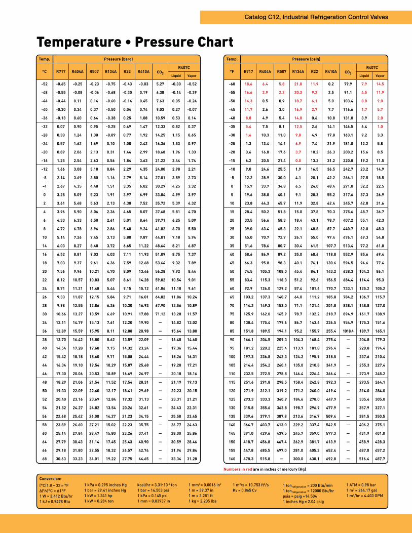
Catalog C12, Industrial Refrigeration Control Valves
Conversion:
(°C)1.8 + 32 = °F
Δ(5 ⁄9)°C = Δ1°F
1 W = 3.412 Btu/hr
1 kJ = 0.9478 Btu
1 kPa = 0.295 inches Hg
1 bar = 29.41 inches Hg
1 kW = 1.341 hp
1 kW = 0.284 ton
kcal/hr = 3.31 10-4 ton
1 bar = 14.503 psi
1 kPa = 0.145 psi
1 mm = 0.03937 in
1 mm2 = 0.0016 in2
1 m = 39.37 in
1 m = 3.281 ft
1 kg = 2.205 lbs
1 m2/s = 10.753 ft2/s
Kv = 0.865 Cv
1 tonrefigeration = 200 Btu/min
1 tonrefigeration = 12000 Btu/hr
psia = psig +14.504
1 inches Hg = 2.04 psig
1 ATM = 0.98 bar
1 m3 = 264.17 gal
1 m3/hr = 4.403 GPM
Temp. Pressure (psig)
°F R717 R404A R507 R134A R22 R410A CO2
R407C
Liquid Vapor
-60 18.6 6.4 5.8 21.8 11.9 0.2 79.9 7.9 14.5
-55 16.6 2.9 2.2 20.3 9.2 2.5 91.1 4.5 11.9
-50 14.3 0.5 0.9 18.7 6.1 5.0 103.4 0.8 9.0
-45 11.7 2.6 3.0 16.9 2.7 7.7 116.6 1.7 5.7
-40 8.8 4.9 5.4 14.8 0.6 10.8 131.0 3.9 2.0
-35 5.4 7.5 8.1 12.5 2.6 14.1 146.5 6.4 1.0
-30 1.6 10.3 11.0 9.8 4.9 17.8 163.1 9.2 3.3
-25 1.3 13.4 14.1 6.9 7.4 21.9 181.0 12.2 5.8
-20 3.6 16.8 17.6 3.7 10.2 26.3 200.2 15.6 8.5
-15 6.2 20.5 21.4 0.0 13.2 31.2 220.8 19.2 11.5
-10 9.0 24.6 25.5 1.9 16.5 36.5 242.7 23.2 14.9
-5 12.2 28.9 30.0 4.1 20.1 42.2 266.1 27.5 18.5
0 15.7 33.7 34.8 6.5 24.0 48.4 291.0 32.2 22.5
5 19.6 38.8 40.1 9.1 28.3 55.2 317.6 37.3 26.9
10 23.8 44.3 45.7 11.9 32.8 62.4 345.7 42.8 31.6
15 28.4 50.2 51.8 15.0 37.8 70.3 375.6 48.7 36.7
20 33.5 56.6 58.3 18.4 43.1 78.7 407.2 55.1 42.3
25 39.0 63.4 65.3 22.1 48.8 87.7 440.7 62.0 48.3
30 45.0 70.7 72.7 26.1 55.0 97.4 476.1 69.3 54.8
35 51.6 78.6 80.7 30.4 61.5 107.7 513.4 77.2 61.8
40 58.6 86.9 89.2 35.0 68.6 118.8 552.9 85.6 69.4
45 66.3 95.8 98.3 40.1 76.1 130.6 594.5 94.6 77.4
50 74.5 105.3 108.0 45.4 84.1 143.2 638.3 104.2 86.1
55 83.4 115.3 118.3 51.2 92.6 156.5 684.4 114.4 95.3
60 92.9 126.0 129.2 57.4 101.6 170.7 733.1 125.2 105.2
65 103.2 137.3 140.7 64.0 111.2 185.8 784.2 136.7 115.7
70 114.2 149.3 153.0 71.1 121.4 201.8 838.1 148.8 127.0
75 125.9 162.0 165.9 78.7 132.2 218.7 894.9 161.7 138.9
80 138.4 175.4 179.6 86.7 143.6 236.5 954.9 175.3 151.6
85 151.8 189.5 194.1 95.2 155.7 255.4 1018.4 189.7 165.1
90 166.1 204.5 209.3 104.3 168.4 275.4 — 204.8 179.3
95 181.2 220.2 225.4 113.9 181.8 296.4 — 220.8 194.4
100 197.3 236.8 242.3 124.2 195.9 318.5 — 237.6 210.4
105 214.4 254.2 260.1 135.0 210.8 341.9 — 255.3 227.4
110 232.5 272.5 278.8 146.4 226.4 366.4 — 273.9 245.2
115 251.6 291.8 298.5 158.4 242.8 392.3 — 293.5 264.1
120 271.9 312.1 319.2 171.2 260.0 419.4 — 314.0 284.0
125 293.3 333.3 340.9 184.6 278.0 447.9 — 335.4 305.0
130 315.8 355.6 363.8 198.7 296.9 477.9 — 357.9 327.1
135 339.6 379.1 387.8 213.6 316.7 509.4 — 381.5 350.5
140 364.7 403.7 413.0 229.2 337.4 542.5 — 406.2 375.1
145 391.0 429.6 439.5 245.7 359.0 577.3 — 431.9 401.0
150 418.7 456.8 467.4 262.9 381.7 613.9 — 458.9 428.3
155 447.8 485.5 497.0 281.0 405.3 652.4 — 487.0 457.2
160 478.3 515.8 — 300.0 430.1 692.8 — 516.4 487.7
Numbers in red are in inches of mercury (Hg)
Temp. Pressure (barg)
°C R717 R404A R507 R134A R22 R410A CO2
R407C
Liquid Vapor
-52 -0.65 -0.25 -0.23 -0.75 -0.43 -0.03 5.27 -0.30 -0.52
-48 -0.55 -0.08 -0.06 -0.68 -0.30 0.19 6.38 -0.14 -0.39
-44 -0.44 0.11 0.14 -0.60 -0.14 0.45 7.63 0.05 -0.24
-40 -0.30 0.34 0.37 -0.50 0.04 0.74 9.03 0.27 -0.07
-36 -0.13 0.60 0.64 -0.38 0.25 1.08 10.59 0.53 0.14
-32 0.07 0.90 0.95 -0.25 0.49 1.47 12.33 0.82 0.37
-28 0.30 1.24 1.30 -0.09 0.77 1.92 14.25 1.15 0.65
-24 0.57 1.62 1.69 0.10 1.08 2.42 16.36 1.53 0.97
-20 0.89 2.06 2.13 0.31 1.44 2.99 18.68 1.96 1.33
-16 1.25 2.54 2.63 0.56 1.84 3.63 21.22 2.44 1.74
-12 1.66 3.08 3.18 0.84 2.29 4.35 24.00 2.98 2.21
-8 2.14 3.69 3.80 1.16 2.79 5.14 27.01 3.59 2.73
-4 2.67 4.35 4.48 1.51 3.35 6.02 30.29 4.25 3.32
0 3.28 5.09 5.23 1.91 3.97 6.99 33.84 4.99 3.97
2 3.61 5.48 5.63 2.13 4.30 7.52 35.72 5.39 4.32
4 3.96 5.90 6.06 2.36 4.65 8.07 37.68 5.81 4.70
6 4.33 6.33 6.50 2.61 5.01 8.64 39.71 6.25 5.09
8 4.72 6.78 6.96 2.86 5.40 9.24 41.82 6.70 5.50
10 5.14 7.26 7.45 3.13 5.80 9.87 44.01 7.18 5.94
14 6.03 8.27 8.48 3.72 6.65 11.22 48.64 8.21 6.87
16 6.52 8.81 9.03 4.03 7.11 11.93 51.09 8.75 7.37
18 7.03 9.37 9.61 4.36 7.59 12.68 53.64 9.32 7.89
20 7.56 9.96 10.21 4.70 8.09 13.46 56.28 9.92 8.44
22 8.12 10.57 10.83 5.07 8.61 14.28 59.02 10.54 9.01
24 8.71 11.21 11.48 5.44 9.15 15.12 61.86 11.18 9.61
26 9.33 11.87 12.15 5.84 9.71 16.01 64.82 11.86 10.24
28 9.98 12.55 12.86 6.26 10.30 16.93 67.90 12.56 10.89
30 10.66 13.27 13.59 6.69 10.91 17.88 71.12 13.28 11.57
34 12.11 14.79 15.13 7.61 12.20 19.90 — 14.82 13.02
36 12.89 15.59 15.95 8.11 12.88 20.98 — 15.64 13.80
38 13.70 16.42 16.80 8.62 13.59 22.09 — 16.48 14.60
40 14.54 17.28 17.68 9.15 14.32 23.24 — 17.36 15.44
42 15.42 18.18 18.60 9.71 15.08 24.44 — 18.26 16.31
44 16.34 19.10 19.54 10.29 15.87 25.68 — 19.20 17.21
46 17.30 20.06 20.53 10.89 16.69 26.97 — 20.18 18.16
48 18.29 21.06 21.54 11.52 17.54 28.31 — 21.19 19.13
50 19.33 22.09 22.60 12.17 18.41 29.69 — 22.23 20.15
52 20.40 23.16 23.69 12.84 19.32 31.13 — 23.31 21.21
54 21.52 24.27 24.82 13.54 20.26 32.61 — 24.43 22.31
56 22.68 25.42 26.00 14.27 21.23 34.15 — 25.58 23.45
58 23.89 26.60 27.21 15.02 22.23 35.75 — 26.77 24.63
60 25.14 27.84 28.47 15.80 23.26 37.41 — 28.00 25.86
64 27.79 30.43 31.14 17.45 25.43 40.90 — 30.59 28.46
66 29.18 31.80 32.55 18.32 26.57 42.74 — 31.94 29.84
68 30.63 33.23 34.01 19.22 27.75 44.65 — 33.34 31.28

Parker Hannifin CorporationRefrigerating Specialties Division2445 South 25th AvenueBroadview, Illinois 60155-3858 USA
Parker Hannifin CorporationHERL Refrigerating Specialties DivisionWankelstrasse 40Cologne, Germany D-50996
RSDC12 04/2013© 2013 Parker Hannifin Corporation
Product specifications subject to change without notice. Visit www.parker.com/refspec for current product information, including the latest version of this catalog.
Regulator, Solenoids, & Check Valves
Valve
Type
Port
Size
Min. PSI Drop
to Open
Manual Open
Position
A4AA4WA2BA2A
AFR-3FFR-2
3⁄4” - 4”5” - 8”
1⁄4” - 3⁄4”1⁄4” - 3⁄4”1⁄2” - 3⁄4”1⁄2” - 3⁄4”
VariesVariesVariesVariesVariesVaries
OUTIN
N/AN/AN/AN/A
S6NS8FS4AS4AS4WS7AS5ASV2S9AS9WCK2
3⁄16”1⁄2”
3⁄4” - 11⁄4”15⁄8” - 4”5” - 8”
3⁄4” - 1”11⁄4” - 3”
1⁄2” - 11⁄4”2” - 4”5” - 8”
11⁄4”- 6”
014201
3.52
10100
ININ
OUTOUTININININ
OUTININ
CK-1CK-3CK4ACK4A
3⁄4” - 6”1⁄2” - 1”1⁄2” - 4”5” - 8”
0.55.0
0.750.6
INN/AN/AN/A
Press. Reg.: Stem In - Increases SetpointFlow Reg.: Stem Out - Increases Flow