specifications and contract documents substation … · 01040 project coordination 2 01090...
TRANSCRIPT
SPECIFICATIONS AND CONTRACT DOCUMENTS
SUBSTATION POWER TRANSFORMER
WITH LOAD TAP CHANGER
FOR
PITTS LANE SUBSTATION
MURFREESBORO ELECTRIC DEPARTMENT
MURFREESBORO, TENNESSEE
engineers • planners
402 BNA Drive, Suite 208
Nashville, TN 37217-2518
JOB NO.: 81742.4
DATE: October, 2018

090718 81742.4
M021596-EU CERTIFICATIONS 00002 - 1
DOCUMENT 00002
CERTIFICATIONS
The Plans and Specifications covered by these Contract Documents were prepared under the
supervision and direction of the undersigned Registered Engineers and/or Architects, whose seals
are affixed below.
_________________________________________________
Joe Nims, P.E.
Electrical Engineer
END OF DOCUMENT

090718 81742.4
M092896-EU CONTENTS 00003 - 1
DOCUMENT 00003
CONTENTS
DIVISIONS 0 and 1 - CONTRACT DOCUMENTS AND GENERAL REQUIREMENTS
Pages
00001 TITLE SHEET 1
00002 CERTIFICATIONS 1
00003 TABLE OF CONTENTS 1
00004 LIST OF DRAWINGS, TABLES & SCHEDULES 1
00021 INVITATION TO BIDDERS 1
00102 INSTRUCTIONS TO BIDDERS 2
00302 BID FORM 7
00531 MATERIALS CONTRACT 3
00711 GENERAL CONDITIONS 7
00811 SUPPLEMENTARY CONDITIONS 2
00900 ADDENDA 1
01040 PROJECT COORDINATION 2
01090 REFERENCE STANDARDS 2
01301 SUBMITTALS 2
01341 SHOP DRAWINGS 4
01721 PROJECT RECORD DOCUMENTS 4
DIVISION 16 - ELECTRICAL
16320 SUBSTATION POWER TRANSFORMER 26
16320D DATA SHEET - SUBSTATION POWER TRANSFORMER 9
16327 LOAD TAP CHANGER 5
END OF DOCUMENT

090718 81742.4
M092096-EU LIST OF DRAWINGS, TABLES & SCHEDULES 00004 - 1
DOCUMENT 00004
LIST OF DRAWINGS, TABLES & SCHEDULES
The following is a list of Contract Drawings which this contract is to be based. These drawings are
entitled Pitts Lane 46/13 kV Substation and dated September 2018 with revision dates (if any), as
noted. They will be supplemented by additional shop and dimensional drawings of materials and
equipment and other drawings where specified.
Drawing Revision
Number Sub-Title Date
E2.1 GENERAL ARRANGEMENT PLAN
END OF DOCUMENT

090718 81742.4
M0073012-EU INVITATION TO BIDDERS 00021 - 1
DOCUMENT 00021
INVITATION TO BIDDERS
Sealed proposals for two 46/13 kV Substation Power Transformers with Load Tap Chargers for the
Pitts Lane Substation will be received by Murfreesboro Electric Department at their office in
Murfreesboro until 2:00 PM local time on November 8, 2018 and immediately thereafter will be
opened, and publicly read.
Proposals shall be received by:
Murfreesboro Electric Department
ATTN: PD Mynatt, General Manager
205 North Walnut Street
Murfreesboro, Tennessee 37130
Transformer Bid Opening: November 8, 2018
The Owner’s preferred carrier is FedEx®.
The Owner reserves the right to reject any or all bids and to waive any informalities or technicalities
therein.
No Bidder may withdraw a bid for a period of thirty (30) days after the date set for opening of bids.
By: Mr. PD Mynatt, General Manager
Murfreesboro Electric Department
END OF DOCUMENT

090718 81742.4
M062912-EU INSTRUCTIONS TO BIDDERS 00102 - 1
DOCUMENT 00102
INSTRUCTIONS TO BIDDERS
Each Bidder shall examine carefully the site of the work to be acquainted with working conditions
and all difficulties that may be involved therein, and shall examine carefully all drawings,
specifications, and other contract documents to be familiar with all of the requirements, terms, and
conditions thereof. Any information relating to the work furnished by the Owner or others, or
failure to make these examinations shall in no way relieve any Bidder from the responsibility of
fulfilling all of the terms of the contract.
The Proposal provides for quotation of a price for one or more bid items, which may be lump sum
bid prices, alternate bid prices or a combination thereof. No payment will be made for items not
set up in the Proposal, unless otherwise provided by contract amendment. All Bidders are
cautioned that they should include in the prices quoted for the various bid items all necessary
allowances for the performance of all work required for the satisfactory completion of the Project.
Bidder is cautioned to verify the completeness of this specification package as listed in Document
00003 - CONTENTS.
Bidder will submit two (2) copies of Document 00302 - PROPOSAL and all of the supporting
documents specified.
Bids that are sent by U.S. Postal Service or private carrier shall be clearly marked "BID ENVELOPE
ENCLOSED." The bid shall be sealed in a separate envelope and shall have the following
information, shown on the outside of the envelope.
BID FOR: Two (2) 46:13 kV 18/24/30 MVA Power Transformer with LTC
BID DUE: November 8, 2018 – 2:00 PM Local Time
OWNER: Murfreesboro Electric Department
ATTN: PD Mynatt, General Manager
205 North Walnut Street
Murfreesboro, TN 37130
The Engineer for this project is:
Allen & Hoshall
Engineers Planners
STREET: BNA Corporate Center
402 BNA Drive, Suite 208
Nashville, Tennessee 37217-2518
PHONE: (615) 399-2661
FAX: (615) 399-2657
CONTACT: Joe Nims, P.E.
ALTERNATE: Jody Cathey, P.E.
The Engineer will represent the Owner in all matters pertaining to this project, including but not
limited to, answering technical questions of prospective bidders, recommendation of awards,
acceptance of shop drawings and similar documents, and approval of invoices prior to payment by
the Owner.

090718 81742.4
M062912-EU INSTRUCTIONS TO BIDDERS 00102 - 2
CHECKLIST FOR BIDDERS - Submit two (2) copies of Document 00302 - PROPOSAL and all
supporting documents as specified:
DOCUMENT 00101: Bid Envelope Information: Enter on sealed bid envelope
DOCUMENT 00302: Date
DOCUMENT 00302: Bid Price:
Base Bid
Alternate Bid
DOCUMENT 00302: Warranty Extension Adder
DOCUMENT 00302: Guaranteed Losses
DOCUMENT 00302: Auxiliary Losses
DOCUMENT 00302: Place of Manufacture
DOCUMENT 00302: Surety Bond Adder
DOCUMENT 00302: Delivery Method
DOCUMENT 00302: Alternate Delivery Date
DOCUMENT 00302: Shop Drawing Schedule
DOCUMENT 00302: FRA Test Adder
DOCUMENT 00302: Labor Contract Expiration Date
DOCUMENT 00302: Required Submittal Data
DOCUMENT 00302: Addenda (if any)
DOCUMENT 00302: Exceptions to the Specifications (if any)
DOCUMENT 00302: Signature
END OF DOCUMENT

090718 81742.4
M052617-EU BID FORM 00302 - 1
DOCUMENT 00302
BID FORM
Date: November 8, 2018 To: Mr. PD Mynatt, General Manager Murfreesboro Electric Department 205 North Walnut Street Murfreesboro, TN 37130 Gentlemen: The undersigned, hereinafter called the "Materialman", hereby proposes to sell and deliver to ______________________________hereinafter called the "Owner" upon the terms and conditions herein stated, the material specified in the attached Specifications dated ______________________, for the following sum:
BASE BID:
ITEM QUANTITY DESCRIPTION UNIT BID PRICE TOTAL BID PRICE
1 2 46/13 kV 18/24/30 MVA Power Transformer with LTC
$______________ $________________
2 LOT Spare Parts: One Spare H, X and X0 bushing (if different than X bushing).
$________________
Losses shall be quoted on a per unit basis. The Guaranteed Evaluated Losses are calculated as outlined in Section 16320 - SUBSTATION POWER TRANSFORMER and Section 16320D – DATA SHEET. The guaranteed losses per unit for the BASE BID are as follows:
No Load Losses Rated Voltage (20°C)
Load Losses, ONAN rating (75°C) Guaranteed Total Losses (excluding auxiliary losses) LTC @ Neutral LTC @ 15 Raise
_______________ kW _________ kW _________ kW _______________ kW, per unit
Auxiliary Losses: First Step of Forced Cooling
Second Step of Forced Cooling
Total Auxiliary Losses
_______________ kW _______________ kW _______________ kW, per unit
Proposals excluding Load Losses at 15 Raise will be rejected.
The LTC mechanism being proposed is a type ___________ (resistive or reactive), manufactured by ___________________ with a maximum current rating of ________ A. The coil construction of the tap winding is a _________________________ (helical, etc) and is _____________ (fully or partially) distributed. If a series transformer is proposed, windings have a _______________ (circular or rectangular) construction. The excited winding has a rated voltage of _____________ V.

090718 81742.4
M052617-EU BID FORM 00302 - 2
If a reactance-type LTC is proposed, loading on the power transformer is limited to ______ percent of its maximum rating if the LTC mechanism stops in a mid-tap position. Other limitations should be discussed as part of the manufacturer’s proposal. If a reactance-type LTC is proposed, the preventative autotransformer (PA) uses _______________ (circular or rectangular) construction. If rectangular construction is proposed, details of the manufacturer’s PA design should be a part of the proposal. OPTIONAL ADDERS WITH PRICING:
The Owner requests an adder for a 4-year extension to the warranty specified in Section 16320 SUBSTATION POWER TRANSFORMER. During this additional 4-year period, the Materialman’s responsibilities are identical to those specified in Section 16320 except that transportation, removal and installation is excluded. The BASE BID price ADDER per unit is $_______________________. The BASE BID price ADDER per unit to provide a 100% surety bond is $______________. The BASE BID price ADDER per unit to have nighttime delivery is $______________. The place of manufacture for the BASE BID is _________________________________.
PROJECT LOCATION AND SCHEDULE: Destination: Pitts Lane 46/13 kV Substation 1733 Wenlon Dr. Murfreesboro, TN 37153 Delivery, Assembly and Field Test Period:
First Unit: November 18, 2019 to December 13, 2019. Second Unit: March 9, 2020 to March 20, 2020. Field test reports shall be submitted within 5 business days after test crews leave the Project Site. Liquidation damages apply to each unit if field tests are not completed within the stated period. Liquidated damages also apply if field tests are not submitted within 5 business day after crews leave the Project Site.
Delivery Constraints: Daytime Delivery: Shipments arriving after 2:00 p.m. on weekdays
(Monday through Thursday) or arriving on weekends or holidays shall not be offloaded until the next working day and the Materialman shall be responsible for any demurrage.
Nighttime Delivery: Each units shall be delivered on different nights to the
Destination beginning at 11:00 p.m. and completed before 4:00 a.m. Materialman shall provide Owner with a copy of its TDOT permit immediately after receipt, Owner requires Materialman’s TDOT permit to coordinate a local permit with the City of Murfreesboro. The Materialman is responsible for any additional costs due to delays in Owner’s receipt of the TDOT permit.
Site Conditions: The transformer(s) are part of rehabilitation of an existing substation. The
substation will be energized during offloading, assembly and field testing. Materialman is responsible for assessing and including an appropriate delivery

090718 81742.4
M052617-EU BID FORM 00302 - 3
method in its BID. Materialman’s shipment lead time is ______________ weeks. Materialman will provide transportation to the Destination by ______________ (e.g., truck, rail, ocean vessel). An alternate Delivery Period of __________ to ____________ is proposed by the Materialman. If this alternate Delivery Period is accepted by the Owner, a price DEDUCT per unit of $___________________ is offered. The Materialman shall provide shop drawings, as specified in Section 01341 – SHOP DRAWINGS, _________ weeks after receipt of order. The Materialman shall provide "FOR CONSTRUCTION" drawings at least 6 weeks prior to shipping. Field Assembly, when required, will be performed by field service representatives from ______________________________ (supply name of Field Service Firm).
LABOR RELATIONS:
The nearest labor contract expiration date associated with the design, manufacture, delivery or installation of the transformer is __________________.
GENERAL:
In submitting this BID FORM, the Materialman agrees as follows: The prices set forth herein include any and all sums which are or may be payable by the Materialman on account of taxes imposed by any taxing authority upon the sale, purchase, or use of the equipment. If any such tax is applicable to the sale, purchase, or use of the equipment, the amount thereof shall be added to the purchase price and paid by the Owner. Owner is exempt from
Tennessee Sales and Use Taxes (§ TCA 67-6-209(e).
The Materialman agrees to the terms and conditions of the Document 00531 - MATERIALS CONTRACT. The prices set forth herein are firm if accepted by the Owner within the period specified in
Document 00021 - INVITATION TO BIDDERS and shall include the cost of:
1. Delivery to the Destination. 2. Offloading onto an Owner furnished concrete pad. 3. Assembly, if any, of bushings, radiators and/or equipment shipped separately from the
main body of the transformer. This includes the cost of a crane and other tools required to complete this assembly.
4. Field Service Representative for inspection, testing, and certification. 5. All other labor or other costs to provide the Owner with transformer filled with insulating
liquid and ready for external connection.
The Evaluated Losses are guaranteed by the Materialman. If transformer test losses exceed the

090718 81742.4
M052617-EU BID FORM 00302 - 4
guaranteed losses, the Contract Amount will be adjusted as described in Section 16320 - SUBSTATION POWER TRANSFORMER.
DELIVERY AND INSTALLATION:
The transformer(s) shall be delivered to the Destination during the Delivery Period specified above. The Delivery Period defines the time during the project schedule from completion of the concrete pad until other project tasks could make the pad inaccessible. Delivery outside the specified Delivery Period could result in liquidated damages being assessed. Field assembly shall be completed on or before the Field Assembly Completion Date.
The Materialman shall be responsible for securing all permits required for shipping to the Destination and shall be responsible for any damages to road and utilities or other damages caused by the Materialman or his Delivery Agent during shipment to Destination. Notice of Shipment - The Materialman shall notify the Owner and Engineer at the following times:
1. 10 days prior to shipment. 2. 24 hours prior to shipment. 3. 24 hours prior to delivery.
Failure to provide notice shall result in Materialman being responsible for any demurrage charges resulting from the unavailability of equipment to unload equipment. The Materialman agrees that all requests for time extensions shall be in writing, and that only such time extensions as are granted by the Owner in writing shall be considered. Time is of the essence in order for the Owner to comply with established construction schedules. Should the Materialman fail to complete the terms of this BID FORM by the Completion Date, after all time extensions granted by the Owner have been added, then in that event the Owner shall have and is hereby given the right to deduct and retain out of such monies which may then be due, or which may become due and payable to the Materialman, the DAMAGE AMOUNT per calendar day as liquidated damages for each and every day that Certification is delayed beyond the Completion Date. The Materialman and Owner agree that liquidated damages are for costs associated with project delay and not as a penalty and that proof of such losses or damages shall not be required. The DAMAGE AMOUNT shall be $ 300 per day.
EVALUATION OF BIDS: In order to determine the lowest responsive and responsible Vendor, the Owner will consider, in addition to the price quoted on the BID FORM, the following:
1. Evaluated Losses. 2. Stated exceptions to the specifications. 3. Method of delivery. 4. Warranty. 5. Delivery time. 6. Work history on previous projects. 7. Qualifications of the Field Service Representatives or Field Service Firm.
The bid prices submitted for spare parts will not be used in the evaluation.

090718 81742.4
M052617-EU BID FORM 00302 - 5
The Materialman shall submit bids on this BID FORM. Submit (2) two unaltered copies of the BID FORM with all blank spaces completed. Each completed BID FORM should also include a copy of the required attachments. There shall be no exceptions for basic bid submitted by the Materialman; however, an alternate, with exceptions, may be bid as an attachment to a basic bid.
BID ATTACHMENTS: Additional information and drawings shall be attached to and become a part of this BID FORM including, but not be limited to, the following:
1. Outline Drawings. 2. Transformer Dimensions, Weights. 3. Transformer Insulating Liquid Capacity (Tank & Total). 4. Winding Design Type. 5. Impedance. 6. Regulation Value. 7. Load Tap Changer Data. 8. Sound Levels At All Ratings. 9. Qualifications of the Materialman’s Field Services Representative. 10. A schedule of field tests, if different from those specified in Section 16320. 11. Complete listing of transformers of proposed design and rating of this manufacturer that
have been short-circuit tested. The listing shall include all units tested and designated as development test or test required by customer specification. Test results, winding type and winding material shall be included. Unsuccessful tests shall be explained with appropriate comments as to design changes and subsequent testing and results.
Failure to submit bid evaluation data as specified can lead to bid rejection.
TITLE AND RISK OF LOSS: Title of each equipment item shall pass to the Owner when all of the following have occurred:
1. Delivery and placement of equipment onto foundation at location specified. 2. Satisfactory inspection for in transit damage. 3. Satisfactory installation and field test by the Materialman's Field Services Representative. 4. Certification that the unit is ready to place in service. 5. Acceptance by the Owner following completion of Item 4. 6. Payment: See Document 00531 - MATERIALS CONTRACT, Article II Payment.
The Materialman acknowledges that he has received the following Addenda (insert Addenda number(s) and date(s) or NONE): ADDENDUM NUMBER DATE _________________________________________ _________ _________________________________________ _________

090718 81742.4
M052617-EU BID FORM 00302 - 6
EXCEPTIONS: Any and all exceptions that the Materialman takes to the attached specifications
shall be itemized on this BID FORM. All items or exceptions not listed on this BID FORM will be
deemed in full compliance of these specifications. Detailed description of the exceptions may be provided elsewhere in the bid materials. The Bidder shall indicate to which specification sections and paragraphs the exceptions apply or indicate no exceptions. Specification Section Associated with EXCEPTION Description of Exception

090718 81742.4
M052617-EU BID FORM 00302 - 7
It is understood by the undersigned that the Owner retains the privilege of accepting or rejecting all or any part of this BID FORM and to waive any informalities or technicalities therein. MATERIALMAN: BY: TITLE: MAILING ADDRESS: DATE: TELEPHONE: FAX:
E-MAIL:__ STREET ADDRESS:
OVERNIGHT SHIPMENT ADDRESS:
PRINCIPAL CONTACT TELEPHONE: E-MAIL:__ ALTERNATE CONTACT TELEPHONE: E-MAIL:__ END OF DOCUMENT
090718 81742.4
M093016-EU MATERIALS CONTRACT 00531 - 1
DOCUMENT 00531
MATERIALS CONTRACT
AGREEMENT made as of___________________________, between Murfreesboro Electric Department
(hereinafter called the "Owner"), a Municipal Electric Utility organized and existing under the laws of
the State of Tennessee and _______________________________ (hereinafter called the "Materialman"), a
corporation organized and existing under the laws of the State of ______________________________.
WHEREAS, the Owner and the Materialman desire to enter into this contract for the furnishing of
materials, supplies and equipment (hereinafter called "Materials") for the Project,
NOW THEREFORE, in consideration of the mutual undertakings herein contained, the parties hereto
agree as follows:
ARTICLE I - GENERAL
SECTION 1. The Materialman agrees to sell and deliver to the Owner and the Owner agrees to
purchase and receive from the Materialman the following Materials in accordance with the provisions of
the Table of Contents, Invitation to Bidders, Bidding Instructions, Materialman's Proposal, General
Conditions, Supplementary Conditions, Specifications and other items, attached hereto and made part
hereof:
Two (2) 46-13 kV Substation Power Transformers with LTC.
Total Contract Price $______________________
ARTICLE II – PAYMENT
Upon the shipment of any Materials hereunder, the Materialman shall submit to the Engineer a detailed
invoice duplicate of the Materials shipped. After verifying the amount is correct, the invoice will be
forwarded to the Owner with a recommendation for payment. Owner shall, within 30 days after receipt
thereof, pay Materialman the amount of 95 percent of the value of the equipment and materials
delivered at the destination but not prior to the Delivery Period contained in the specifications. After
energization of the equipment or within four (4) calendar months after delivery, whichever is first, the
Owner will promptly pay the additional 5 percent due less any sum Owner is entitled to set off,
including but not limited to liquidated damages to which Owner is entitled.
ARTICLE III - DEFECTIVE MATERIALS AND WORKMANSHIP
SECTION 1. All materials furnished hereunder shall be subject to the inspection, tests, and approval of
the Owner and the Materialman shall furnish all information required concerning the nature or source of
any Materials and provide adequate facilities for testing and inspecting the Materials at the Plant of the
Materialman.
SECTION 2. The materials furnished hereunder shall become the property of the Owner when delivery
at the specified location is made; no transit damage is noted after delivery; Materialman has
satisfactorily installed, tested and certified the materials are ready to be placed in service; Owner has
accepted installation and field tests completed by Materialman; and payment, as defined in Article II,
has been made. Owner may reject any such materials as do not comply with the Specifications for
090718 81742.4
M093016-EU MATERIALS CONTRACT 00531 - 2
materials and warranties of the Materialman and manufacturers and any defective materials either
before or after incorporation of such materials into the Project; provided such rejection is made in
accordance with Warranty requirements of the attached technical section of this Specification. Upon
any such rejection, the Materialman shall replace the rejected Materials with Materials complying with
the Specifications for Materials and warranties at the original delivery destination(s). The Owner shall
return the rejected materials at the same destination(s). In the event of the failure of the Materialman
to replace rejected Materials, the Owner may make such replacement and the cost and expense thereof
shall be paid by and recoverable from the Materialman.
ARTICLE IV - MISCELLANEOUS
SECTION 1. All manufacturer's guaranties of Materials shall be transferred and assigned to the Owner
upon delivery of any Materials and before payment is made for such Materials. Such guaranties shall
be in addition to those required of the Materialman by other provisions of this contract.
SECTION 2. The Materialman shall hold harmless and indemnify the Owner, its agents and employees,
from any and all claims, suits and proceedings for infringement of any patent or patents covering
Materials purchased hereunder. The Materialman shall defend any suit or proceeding brought against
the Owner, its agents or employees, based upon a claim that the materials or any part thereof
constitute an infringement of any patent, or if the Materialman shall fail to defend such suit or
proceeding, the Owner may do so and the Materialman shall make reimbursement for the expense of
such litigation. If the Materials, or any part thereof, are held to constitute infringement and the use
thereof is enjoined the Materialman shall, at its own expense, either procure for the Owner the right to
continue to use the Materials, or such part thereof, or shall replace the Materials, or such part thereof,
with non-infringing materials.
SECTION 3. Simultaneously with the final payment to the Materialman, as provided herein, the
Materialman shall deliver to the Owner duplicate original releases of lien of subcontractors, if any.
SECTION 4. In the event that any of the provisions of this contract are violated by the Materialman or
by any of the Materialman's subcontractors, the Owner may serve a written notice of intention to
terminate such contract upon the Materialman, which notice shall specify the reasons therefor. Unless
within ten (10) days after the serving of such notice upon the Materialman such violation shall cease
and an arrangement for the correction thereof satisfactory to the Owner be made, this contract shall,
upon the expiration of the said ten days, cease and terminate. In the event of any such termination,
the Owner may purchase the Materials necessary for complete performance of this contract for the
account and at the expense of the Materialman, and the Materialman shall be liable to the Owner for
any excess cost occasioned thereby. The foregoing shall be in addition to every right or remedy now
or hereafter existing at law or in equity or by statute.
SECTION 5. Each and all of the covenants and agreements, herein contained shall extend to and be
binding upon the successors and assigns of the parties hereto. However, the Materialman shall not
assign this contract or any part thereof or enter into any contract with any person, firm or corporation
for the performance of the Materialman's obligations hereunder, or any part thereof, without the
approval in writing, of the Owner.
090718 81742.4
M093016-EU MATERIALS CONTRACT 00531 - 3
IN WITNESS WHEREOF, the parties hereto have caused this Agreement to be executed by their duly
authorized representatives all as of the day and year first above written.
Owner: Murfreesboro Electric Department Materialman:
205 North Walnut Street
Murfreesboro, TN 37130
Signed: Signed: _______________________________________
Type/Print: Type/Print: _____________________________________
Title: Title: ___________________________________________
END OF DOCUMENT

090718 81742.4
M061596-EU GENERAL CONDITIONS 00711 - 1
DOCUMENT 00711
GENERAL CONDITIONS
TABLE OF CONTENTS
1. DEFINITIONS ..................................................................................................... 2
2. ENGINEER/ARCHITECT'S DECISION ..................................................................... 2
3. DRAWINGS AND SPECIFICATIONS ..................................................................... 3
4. STANDARD PUBLICATIONS ............................................................................... 3
5. STANDARD EQUIPMENT AND EQUIPMENT INSTALLATION ................................... 3
6. STANDARDS FOR MATERIALS ............................................................................ 4
7. PATENTS ......................................................................................................... 4
8. CONTRACT SECURITY ....................................................................................... 4
9. SUBCONTRACTING ............................................................................................ 4
10. LIQUIDATED DAMAGES ..................................................................................... 5
11. NOTICES AND SERVICE THEREOF ....................................................................... 5
12. RIGHTS OF THE OWNER TO TERMINATE CONTRACT ............................................ 6
13. ASSIGNMENT OF CONTRACT ............................................................................. 6
14. WARRANTY ...................................................................................................... 6
15. MODIFICATIONS TO GENERAL CONDITIONS ........................................................ 7

090718 81742.4
M061596-EU GENERAL CONDITIONS 00711 - 2
DOCUMENT 00711
GENERAL CONDITIONS
1. DEFINITIONS
A. The word "Owner" means the person(s), or organization, or municipality to which the
Proposal is addressed.
B. The words "Engineer", "Architect", "Engineer/Architect" mean ALLEN & HOSHALL,
Architects Engineers.
C. The word “Materialman”, “Contractor”, or “Bidder” means the successful Bidder to whom
the contract is awarded.
D. The words "install", "furnish", "provide", or words of like import mean the Materialman
shall install, furnish, or provide, and similarly the words "approved", "authorized",
"required", "satisfactory", "acceptable", or words of like import mean approved by,
authorized by, required by, satisfactory to, or acceptable to the Engineer/Architect, unless
otherwise expressly stated.
E. The words "indicated", "shown", "detailed", or "scheduled" mean indicated, shown,
detailed, or scheduled on the contract documents, specifications, or drawings, unless
otherwise expressly stated.
F. The word "work" means the labor, materials, equipment, supplies, and services to be
furnished under the contract, and the performing of all duties and obligations required by
the contract documents.
G. The word "submit" means the Materialman shall submit to the Engineer/Architect for
approval, unless otherwise expressly stated.
H. The word "provide" means the Materialman shall furnish and install, complete and ready for
use, unless otherwise expressly stated.
I. The word "selected" means selected by the Engineer/Architect, unless otherwise expressly
stated.
2. ENGINEER/ARCHITECT'S DECISION
A. The Engineer/Architect shall in all cases determine the amount, quality, acceptability, and
fitness of the several kinds of finished work and materials which are to be paid for
hereunder, and shall decide all questions which may arise as to fulfillment of this contract
on the part of the Materialman, and the Engineer/Architect’s interpretation of the contract
and the Engineer/Architect’s determination and decision thereon shall be final and
conclusive; such determinations and decisions, in case any question arises, shall be a
condition precedent to the Materialman’s right to receive any money hereunder. The
Engineer/Architect shall have the right to correct all clerical, mathematical, or minor errors
or omissions in the specifications when such corrections are necessary for the proper
coordination of the contract documents.

090718 81742.4
M061596-EU GENERAL CONDITIONS 00711 - 3
3. DRAWINGS AND SPECIFICATIONS
A. The drawings accompanying these specifications and forming a part thereof are listed
elsewhere and together with the specifications they cover the work to be performed under
the Contract. The Materialman and each Subcontractor employed on this work shall
carefully examine all contract drawings and read all specifications. They will be bound by
all things therein affecting their special work no matter under what heading they may
appear.
B. The drawings and specifications are mutually explanatory and supplementary, and all
features covered in one and not in the other shall have the same force and effect as though
covered in both. In the event of any conflicts between the drawings and specifications,
the Engineer/Architect’s decision shall govern. Should any error, discrepancy, or variance
be discovered in the drawings or specifications, the Materialman (or Subcontractor, as the
case may be) shall immediately notify the Engineer/Architect before beginning the work and
submit the question to the Engineer/Architect for his interpretation and decision. The
Engineer/Architect will be governed by overall meaning of the documents.
C. No deviations from the drawings and specifications shall be made without the
Engineer/Architect’s prior written approval.
D. The GENERAL CONDITIONS and the SUPPLEMENTARY CONDITIONS shall apply to each
and every division and/or section of the Technical Specifications, as fully as if quoted
verbatim therein.
4. STANDARD PUBLICATIONS
A. Wherever in these documents reference is made to standard specifications, standards,
codes, or other standard publications, such as "ASTM" (American Society for Testing and
Materials), "AASHTO" (American Association of State Highway and Transportation
Officials), "ANSI" (American National Standards Institute), "AWWA" (American
Waterworks Association), "ACI" (American Concrete Institute), "AISC" (American Institute
of Steel Construction), "AWS" (American Welding Society), Federal Specifications, "NEC"
(National Electrical Code), or others, in all cases the latest published editions of such
referenced standard publications in effect at the time of receipt of bids shall apply.
5. STANDARD EQUIPMENT AND EQUIPMENT INSTALLATION
A. Except where special equipment is required, it is the general intent of the Technical
Specifications that manufacturers' standard equipment shall be furnished, and minor
variations from the Technical Specifications to accommodate manufacturers' standard
equipment will be permissible, provided that the proposed equipment complies substantially
with the Technical Specifications, and that it will accomplish the required results, all to the
Engineer/Architect’s satisfaction.
1. In addition to the requirements specified in the Technical Specifications, each item of
equipment shall have all features and accessories as standard with its manufacturer
and/or required for a complete operational unit.
090718 81742.4
M061596-EU GENERAL CONDITIONS 00711 - 4
6. STANDARDS FOR MATERIALS
A. All materials shall be new. Used or salvaged materials shall not be considered unless
specifically authorized by the Engineer/Architect.
7. PATENTS
A. The Materialman shall hold and save harmless the Owner and its officers, agents, servants,
and employees from liability of any patented or unpatented invention, process, article, or
appliance manufactured or used in the performance of the contract, including its use by the
Owner, unless otherwise specifically stipulated in the Contract Documents.
8. CONTRACT SECURITY
A. The Materialman shall furnish a surety bond in an amount equal to at least 100 percent of
the contract price as security for the faithful performance of this contract and for the
payment of all persons performing labor and furnishing materials in connection therewith.
The surety shall be a bonding company or companies legally authorized to do business in
the State in which the work is located.
B. The Owner shall have the right to waive the surety bond requirements, in which case the
Materialman shall reduce his bid price in the amount of the Materialman’s cost for such
security.
9. SUBCONTRACTING
A. The Materialman shall not award any subcontract to any Subcontractor without the
Engineer/Architect’s prior approval. Only those Subcontractors of proven ability whose
reputation is known to the Engineer/Architect for executing first-class work, will be
approved. The Engineer/Architect’s approval will not be given until the Materialman
submits to the Engineer/Architect an itemized written statement designating the name of
each Subcontractor, and the amount of each subcontract. This statement shall also
designate the items of the contract which the Materialman proposes to execute directly
with his own organization. The amount of these items, combined with the amounts of the
various subcontract proposals, shall correspond to the contract price for the entire project.
The contract will not be signed until all subcontracts have been approved.
B. The Materialman shall be as fully responsible to the Owner for the acts and omissions of
his Subcontractors, and of persons either directly or indirectly employed by them, as he is
for the acts and omissions of persons directly employed by him.
C. The Materialman shall cause appropriate provisions to be inserted in all subcontracts
relative to the work to bind Subcontractors to the Materialman by the terms of the General
Provisions and other Contract Documents insofar as applicable to the work of
Subcontractors, and give the Materialman the same power as regards terminating any
subcontract that the Owner may exercise over the Materialman under any provisions of the
Contract Documents.
D. Nothing contained in this contract shall create any contractual relation between any
Subcontractor and the Owner. It is specifically pointed out that the contractual relationship
shall exist between the Owner and the Materialman only. It is the Materialman’s duty, in
his own interest, to enter into subcontractural agreements in strict accordance with all

090718 81742.4
M061596-EU GENERAL CONDITIONS 00711 - 5
provisions of the Contract Documents. The failure of the Materialman to make the proper
agreements with his Subcontractors and suppliers shall in no way relieve the Materialman
of his responsibilities and obligations to the Owner.
E. The Materialman and all Subcontractors for the various branches of work employed on the
project shall cooperate fully with each other to facilitate the progress of the work, and to
avoid all interferences between the various parts of the work.
F. Whenever his work is in progress, each Subcontractor shall have present at the job site a
Job Superintendent, foreman, or other duly authorized agent with authority to control the
Subcontractor's work. This duly authorized agent shall meet with the approval of the
Engineer/Architect and the Owner. The Owner reserves the right to remove from the
project the Subcontractor's agent or any other employee of the Subcontractor, if, in the
Engineer/Architects or Owners judgement, such removal is necessary to protect the
Owner’s interest.
10. LIQUIDATED DAMAGES
A. If so stated in the PROPOSAL, the time of completion of the construction is of the essence
of the contract and should the Materialman neglect, refuse, or fail to complete the work to
be done under the contract within the time stated in the PROPOSAL, after all extensions of
time granted by the Owner have been added, then in that event the Owner shall have and
is hereby given the right to deduct and retain out of such monies which may then be due,
or which may become due and payable to the Materialman for the work to be done under
this contract, the amount stated in the PROPOSAL per calendar day for each and every day
that the work is delayed in its completion beyond the specified time. The amount stated in
the PROPOSAL will be held by the Owner to pay Engineering, Architectural, and legal fees
and other costs occasioned by the delay in completion of construction.
11. NOTICES AND SERVICE THEREOF
A. All notices, demands, requests, instructions, approvals, and claims shall be in writing.
B. Each notice to or demand upon the Materialman shall be sufficiently given if delivered at
the office of the Materialman shown by him in the Bid (or at such other office as the
Materialman may from time to time designate to the Owner in writing), or if deposited in
the United States mail in a sealed postage-prepaid envelope, or if delivered with charges
prepaid to any telegraph company for transmission, in each case addressed to such office.
C. Unless otherwise specified in writing to the Materialman, all papers required to be delivered
to the Owner shall be delivered to the Engineer/Architect, and each notice to or demand
upon the Owner shall be sufficiently given if delivered to the Engineer/Architect’s office, or
if deposited in the United States mail in a sealed postage-prepaid envelope, or delivered
with charges prepaid to any telegraph company for transmission, in each case addressed to
the Engineer/Architect, or to such other representative of the Owner or to such other
address as the Owner may subsequently specify in writing to the Materialman for such
purposes.
D. Each such notice or demand shall be deemed to have been given or made as of the time of
actual delivery, or (in the case of mailing) when it should have been received in due course
of post, or (in case of telegrams) at the time of actual receipt, as the case may be.

090718 81742.4
M061596-EU GENERAL CONDITIONS 00711 - 6
12. RIGHTS OF THE OWNER TO TERMINATE CONTRACT
A. If the Materialman should be adjudged bankrupt, or if he should make a general assignment
for the benefit of his creditors, or if a receiver should be appointed for the Materialman or
any of his property, or if he should persistently or repeatedly refuse or fail to supply enough
properly skilled workmen or proper material, or if he should refuse or fail to make prompt
payment to persons supplying labor or material for the work under the Contract, or
persistently disregard instructions or fail to observe or perform any provisions of the
Owner’s instructions, or fail to observe or perform any provisions of the Contract
Documents, or otherwise be guilty of a substantial violation of any provision of the
Contract Documents, then the Owner may by at least five days prior written notice to the
Materialman without prejudice to any other rights or remedies of the Owner in the
premises, terminate the Materialman’s right to proceed with the work. The foregoing
provisions are in addition to, and not in limitation of, the rights of the Owner under all other
provisions of the Contract Documents.
13. ASSIGNMENT OF CONTRACT
A. The Materialman shall not assign the whole or any part of this contract or any monies due
or to become due hereunder without the Owner’s written consent. In case the Materialman
assigns all or any part of any monies due or to become due under this contract, the
instrument of assignment shall contain a clause substantially to the effect that it is agreed
that the right of the assignee in and to any monies due or to become due to the
Materialman shall be subject to prior liens of all persons, firms, and corporations for
services rendered or materials supplied for the performance of the work called for in this
contract.
14. WARRANTY
A. All material furnished by the Materialman, covered by the drawings and specifications and
official modifications thereof, shall be warranted by the Materialman for a period of one
year from the date of acceptance by the Owner. All necessary repairs required during this
period due to defective workmanship or material shall be made promptly by the
Materialman at his facilities or at the customer's site, whichever is best, without cost to
the Owner, including all costs for transportation in both directions between the
manufacturer's facilities and the delivery site, including Owners costs for removal and
installation, at times convenient to the Owner.
B. After the beginning of the warranty period, the Materialman shall not be responsible for
lubrication, filter servicing, adjusting of belts and other items normally requiring periodic
adjustments, cleaning out strainers, and other normal maintenance operations, all of which
shall be the Owner’s responsibility.
C. The Engineer/Architect shall have the sole right to establish the beginning of the warranty
period for all portions of the project, and if so stated in the SUPPLEMENTARY CONDITIONS
or the TECHNICAL SPECIFICATIONS, the guarantee period shall not begin until a trial run
has been completed with satisfactory operation for the period of time stated in the
SUPPLEMENTARY CONDITIONS or the TECHNICAL SPECIFICATIONS.

090718 81742.4
M061596-EU GENERAL CONDITIONS 00711 - 7
15. MODIFICATIONS TO GENERAL CONDITIONS
A. Modifications to these GENERAL CONDITIONS, if any, shall be as specified in
SUPPLEMENTARY CONDITIONS.
END OF DOCUMENT

090718 81742.4
M082616-EU SUPPLEMENTARY CONDITIONS 00811 - 1
DOCUMENT 00811
SUPPLEMENTARY CONDITIONS
7.PATENTS
1. Delete Paragraph A and insert in its place:
A. The Materialman shall hold harmless and indemnify the Owner, its agents and
employees, from any and all claims, suits and proceedings for infringement of any
patent or patents covering Materials purchased hereunder. The Materialman shall
defend any suit or proceeding brought against the Owner, its agents or
employees, based upon a claim that the materials or any part thereof constitute
an infringement of any patent, or if the Materialman shall fail to defend such suit
or proceeding, the Owner may do so and the Materialman shall make
reimbursement for the expense of such litigation. If the Materials, or any part
thereof, are held to constitute infringement and the use thereof is enjoined the
Materialman shall, at its own expense, either procure for the Owner the right to
continue to use the Materials, or such part thereof, or shall replace the Materials,
or such part thereof, with non-infringing materials.
8. CONTRACT SECURITY
1. Delete phrase in Paragraph B “, in which case the Materialman shall reduce his bid
price in the amount of the Materialman’s cost for such security”.
2. The Bidder shall provide the cost for a 100% performance bond on the Bid Form.
14. BASIC WARRANTY
1. The length of warranty shall be as established in the appropriate technical sections of
the Contract Documents and Specifications.
2. Bids will not be accepted from a Materialman that does not provide a Bid Price Adder
for the 4-year warranty extension.
12. RIGHTS OF THE OWNER TO TERMINATE CONTRACT
1. Paragraph A, ninth line delete "five" and substitute "ten" therefore.
15. MODIFICATIONS TO GENERAL CONDITIONS
1. Add a new paragraph immediately after Paragraph A which is to be read as follows:
B. Prior to Execution of the Contract, The liability insurance shall be provided with
the following as to limits of coverage and certain other special provisions (if any):
1. Workers’ Compensation - In accordance with the laws of the State.
2. Contractor shall provide Comprehensive General Liability insurance, written
on a Job Site Basis and name the Owner and Engineer as additionally
insured, as follows on an Occurrence Form:

090718 81742.4
M082616-EU SUPPLEMENTARY CONDITIONS 00811 - 2
General Liability - General Aggregate: $1,000,000
Completed Operations: $1,000,000
Property Damage: $1,000,000 each occurrence
Personal Injury: $1,000,000 annual aggregate
Each Occurrence: $1,000,000
Auto Liability - Combined Single Limit: $1,000,000
Bodily Injury and $ 500,000 each person
Property Damage: $ 500,000 each accident
$1,000,000 annual aggregate]
[Umbrella Liability - Aggregate: $3,000,000
Each Occurrence: $3,000,000
3. The required insurance policies shall include a waiver of subrogation in
favor of the Owner and Engineer.
4. All insurance must be written with an insurance company authorized to do
business in the State of Tennessee and shall be placed with insurers with
an A.M. Best rating of A- VIII or better.
END OF DOCUMENT

090718 81742.4
M081712-EU ADDENDA 00900 - 1
DOCUMENT 00900
ADDENDA
1. INTERPRETATIONS - ADDENDA
A. Interpretations and Addenda for questions concerning the meaning or intent of the Contract
Documents and response of these will be made through the issuing of Addenda.
B. All Addenda are incorporated, by reference, into the Contract. Failure of any Bidder or sub-
bidder to receive any addenda shall not relieve the Bidder of any obligation with respect to
their Bid.
C. All Addenda and modifications to the Contract Documents shall be inserted and indexed
numerically in this location behind this page and coordinated as instructed in each
Addendum.
END OF DOCUMENT
090718 81742.4
060100-EU PROJECT COORDINATION 01040 - 1
SECTION 01040
PROJECT COORDINATION
PART 1. GENERAL
1.01 SECTION INCLUDES
A. Coordination
B. Project Representatives and Addresses
1.02 COORDINATION
A. All work, submittals, and testing shall be coordinated with the Work listed in the Contract
Documents to assure efficient progress of the Project Construction. 1.03 PROJECT REPRESENTATIVES AND ADDRESS
A. Owner: Murfreesboro Electric Department
MAIL: P.O. Box 9(37133-0009) STREET: 205 North Walnut Street
Murfreesboro, TN 37130
PHONE: (615) 893-5514 FAX: (615) 893-8375
Contact: Mr. Jackie Whitaker Alternate: Mr. Mark Peek
B. Engineer: Allen & Hoshall
Engineers Planners
STREET: BNA Corporate Center 402 BNA Drive, Suite 208 Nashville, Tennessee 37217-2518
PHONE: (615) 399-2661 FAX: (615) 399-2657 Contact: Mr. Joe Nims e-mail: [email protected] Alternate: Mr. Jody Cathey e-mail: [email protected]
C. All correspondence to the Owner shall be addressed as in Article 1.03, A.
D. All correspondence, submittals, shop drawings, test reports, instruction manuals, operation manuals and any other pertinent Project materials shall be addressed to the Engineer as in Article 1.03, B.
E. Forward a copy of all correspondence addressed to the Owner to the Engineer.
090718 81742.4
060100-EU PROJECT COORDINATION 01040 - 2
F. Notify Owner and Engineer of the Primary Project Representative, Alternate Project Representative, mailing address, package delivery address, phone number (normal working hours), phone number (after working hours) and fax number.
G. All correspondence, submittals or other items associated with the Contract shall be
identified by the Project Owner and Project name as listed in the Contract Documents.
PART 2. PRODUCTS
(NOT USED)
PART 3. EXECUTION
(NOT USED)
END OF SECTION

090718 81742.4
060100-EU REFERENCE STANDARDS 01090 - 1
SECTION 01090
REFERENCE STANDARDS
PART 1. GENERAL
1.01 SECTION INCLUDES
A. Quality Assurance
B. Schedule of References
1.02 QUALITY ASSURANCE
A. Comply with latest revision of the standard for all equipment, materials and labor, except
when more rigid requirements are specified or are required by applicable codes.
B. Request clarification from Engineer before proceeding, should specified reference standards
conflict with Contract Documents.
1.03 SCHEDULE OF REFERENCE
A. Documents and/or Standards from the following agencies may be referenced in the
Contract Documents:
AA Aluminum Association
AASHTO American Association of State Highway and Transportation Officials
ACI American Concrete Institute
AISC American Institute of Steel Construction
ANSI American National Standards Institute
ASCE American Society of Civil Engineers
ASME American Society of Mechanical Engineers
ASTM American Society for Testing and Materials
AWS American Welding Society
CRSI Concrete Reinforcing Steel Institute
CSI Construction Specifications Institute
EEI Edison Electric Institute
EPA Environmental Protection Agency
ICEA Insulated Cable Engineers' Association

090718 81742.4
060100-EU REFERENCE STANDARDS 01090 - 2
IEEE Institute of Electrical and Electronics Engineers
NEC National Electrical Code
NEMA National Electrical Manufacturers' Association
NESC National Electrical Safety Code
NFPA National Fire Protection Association
OSHA Occupational Safety and Health Administration
SSPC Steel Structures Painting Council
RUS Rural Utility Service
UL Underwriters' Laboratories, Inc.
END OF DOCUMENT
090718 81742.4
M032415-EU SUBMITTALS 01301 - 1
SECTION 01301
SUBMITTALS
PART 1. GENERAL
1.01 SECTION INCLUDES
A. Submittal Procedures
B. Submittal Schedule
1.02 RELATED SECTIONS
A. DIVISIONS 0 and 1 - CONTRACT DOCUMENTS, and GENERAL REQUIREMENTS: These
shall apply to all work included in this section.
B. Section 01040 - PROJECT COORDINATION
C. Section 01341 - SHOP DRAWINGS
D. Section 01721 - PROJECT RECORD DOCUMENTS
1.03 SUBMITTAL PROCEDURES
A. Transmit each submittal with transmittal letter or Engineer accepted form.
B. Submit shop drawings as specified in Section 01341 - SHOP DRAWINGS
C. Identify Owner’s name, project title, pertinent drawing sheet and detail number(s), and
specification section number, as appropriate.
D. Schedule submittals to expedite the project, and deliver to Engineer with copy of
transmittal letter to Owner's representative as identified in Section 01040 - PROJECT
COORDINATION. Coordinate submission of related items.
E. Identify variations from Contract Documents and product or system limitations which may
be detrimental to successful performance of the completed Work.
F. Provide space for Contractor and Engineer review stamps.
G. Revise and resubmit submittals as required, identify all changes made since previous
submittal.
1.04 SUBMITTAL SCHEDULE
A. Provide a submittal schedule indicating review dates and return dates required to maintain
project schedule.

090718 81742.4
M032415-EU SUBMITTALS 01301 - 2
1.05 SUBMITTAL MATRIX
A. The following matrix shows the types of submittals required under each section of the
technical specifications. Details can be found in the appropriate technical sections.
Section
Num
ber
Bill of
Mate
rials
Shop
Dra
win
gs
Pro
duct
Data
Calc
ula
tions
Cert
ific
ations
MIX
Desig
n
Test
Report
s
O&
M
Manuals
16320 X X X X
16327 X X X
END OF SECTION
090718 81742.4
M091616-EU SHOP DRAWINGS 01341 - 1
SECTION 01341
SHOP DRAWINGS
PART 1. GENERAL
1.01 SECTION INCLUDES
A. Shop Drawing submittals
B. Final/Record/As-Built Drawings are specified in Section 01721 - PROJECT RECORD
DOCUMENTS
1.02 RELATED SECTIONS
A. DIVISIONS 0 and 1 - CONTRACT DOCUMENTS, and GENERAL REQUIREMENTS: These
shall apply to all work included in this section.
B. Section 01301 - SUBMITTALS
C. Section 01721 - PROJECT RECORD DOCUMENTS
1.03 SHOP DRAWINGS
A. Shop drawings shall include: fabrication, erection, layout, and setting drawings; material
lists; manufacturer's catalog sheets and/or descriptive data for materials and equipment
showing dimensions, performance characteristics, and capacities; wiring and control
diagrams; electrical characteristics, and capacities; and other pertinent information as
required to obtain approval of the items involved.
B. Drawings shall be presented in a clear and thorough manner.
1. Details shall be identified by reference to sheet and detail numbers shown on Contract
Drawings and Specification Sections.
C. Minimum sheet size: 8½" x 11".
D. Maximum sheet size: 22" x 34"
1.04 PRODUCT DATA
A. Preparation:
1. Clearly mark each copy to identify pertinent products or models.
2. Show performance characteristics and capacities.
3. Show dimensions and clearances required.
B. Manufacturer's standard schematic drawings and diagrams:
1. Modify drawings and diagrams to delete information which is not applicable to the
Work.
090718 81742.4
M091616-EU SHOP DRAWINGS 01341 - 2
2. Supplement standard information to provide information specifically applicable to the
Work.
1.05 MATERIALMAN RESPONSIBILITIES
A. Designate in the submittal schedules, the dates for submission and the dates that reviewed
Shop Drawings and product data will be required to maintain delivery schedule.
B. Review Shop Drawings and Product Data prior to submission. Materialman shall allocate
10 business days (excluding holidays) in the project schedule for the Engineer’s initial
review. Additional time may be necessary for resubmissions.
C. Determine and verify:
1. Catalog numbers and similar data
2. Conformance with specifications
D. Coordinate each submittal with requirements of the Work and of Contract Documents.
E. Notify the Engineer in writing (include e-mail), in advance of submission, of any deviations
in the submittals from requirements of the Contract Documents. Materialman requested
deviations may require additional supporting documentation before the Engineer acts on the
request.
F. Begin no fabrication or work which required submittals until return of submittals with
satisfactory review.
1.06 SUBMISSION REQUIREMENTS
A. Make submittals promptly in accordance with approved schedule.
B. Number of submittals required:
1. Shop Drawings: Submit one (1) copy of electronic data files of all drawings prepared
for the project. Electronic data files shall be either a Design Web Format (.DWF) or a
Portable Document Format (PDF) format. Raster based scans (.TIF, .PCX, or .GIF)
files of manual drawings are not acceptable.
2. Product Data: Submit one electronic (1) copy of product data of all items for which
product data is specified in other sections. Electronic data files shall be in a PDF
format.
3. Shop Drawings and Product Data can be provided on a CD-ROM or via e-mail. When
submittal data is delivered via e-mail, it is the Materialman’s responsibility to verify
receipt by the Engineer.
C. Submittals shall contain:
1. Submittal identification number. Submittals shall be numbered consecutively. Re-
submittals shall use the same submittal number with an alphabetic suffix added.

090718 81742.4
M091616-EU SHOP DRAWINGS 01341 - 3
2. The date of submission and the dates of any previous submissions.
3. The Owner’s name, project title and number.
4. Contract identification.
5. Identification of the project, with the specification section number.
6. Relation to adjacent or critical features of the work or materials.
7. Applicable standards, such as ASTM or Federal Specification numbers.
8. Identification of deviations from Contract Documents.
9. Identification of revisions on resubmittals.
10. A 3"x 3" blank space for Materialman and Engineer stamps.
1.07 RETURN FOR RESUBMISSION
A. The Engineer will return for resubmission all shop drawings submitted without the above
specified approval and certification which in the Engineers opinion contain numerous
discrepancies, have not been checked, or do not meet the requirements for submission.
1.08 REVIEW OF SUBMITTALS
A. The Engineer will review, mark and date all submitted shop drawings. One (1) electronic set
will be returned to the Materialman and remaining sets will be retained by the Engineer.
When submittal data is returned via e-mail, it is the Engineer’s responsibility to verify
receipt by the Materialman. Materialman shall make corrections and changes as indicated.
B. Resubmit shop drawings as specified above, until satisfactory review has been obtained.
Corrections and/or changes indicated on shop drawings by Engineer/Owner shall not be
considered as an extra work order.
C. After satisfactory "Review" or "Furnish as Corrected" has been obtained for all shop
drawings, a set of shop drawings marked "FOR CONSTRUCTION" shall be furnished to the
Engineer in the format specified in Article 1.06 above. Materialman shall provide “FOR
CONSTRUCTION” drawings within 21 days of receipt of the Engineer’s satisfactory review
of all shop drawings.
D. Review of shop drawings by the Engineer will be general only, and such review will not
relieve the Materialman of responsibility for accuracy of such shop drawings, proper fitting,
coordination, construction of work, and furnishing materials required by the Specifications
but not indicated on shop drawings. Review of shop drawings shall not be construed as
approving departures from the Specifications.
1.09 ENGINEER DUTIES
A. Review submittals with reasonable promptness and in accordance with schedule.
B. Affix stamp and initials or signature, and indicate requirements for resubmittal, or
satisfactory review of submittal.

090718 81742.4
M091616-EU SHOP DRAWINGS 01341 - 4
C. Return submittals to Materialman for distribution, or for resubmission.
PART 2. PRODUCTS
(NOT USED)
PART 3. EXECUTION
(NOT USED)
END OF SECTION

090718 81742.4
M062918-EU PROJECT RECORD DOCUMENTS 01721 - 1
SECTION 01721
PROJECT RECORD DOCUMENTS
PART 1. GENERAL
1.01 SECTION INCLUDES
A. Final “As-Built” record drawings
B. Factory test results
C. Operation/Maintenance manuals
1.02 RELATED SECTIONS
A. DIVISIONS 0 and 1 - CONTRACT DOCUMENTS, and GENERAL REQUIREMENTS: These
shall apply to all work included in this document.
B. Other requirements affecting Project Record Documents may appear in pertinent other
Sections of these Specifications.
1.03 SUBMITTALS
A. Comply with pertinent provisions of GENERAL CONDITIONS and Section 01301 -
SUBMITTALS.
B. Prior to submitting request for final payment, submit the final Project Record Documents to
the Engineer/Architect for approval.
1.04 MATERIALMAN RESPONSIBILITIES
A. The Materialman shall provide final "As-Built" record drawings of the work with all revisions
in incorporated.
B. The Materialman shall provide factory test results, as applicable, for all material furnished.
C. The Materialman shall provide complete operation and maintenance manuals for all
equipment furnished.
PART 2. PRODUCTS
(NOT USED)
PART 3. EXECUTION
3.01 FINAL DRAWINGS
A. At completion of project, the Materialman shall incorporate all revisions into the shop
drawings to provide a complete set of final drawings. The drawings shall be marked as
"Final-As Constructed".

090718 81742.4
M062918-EU PROJECT RECORD DOCUMENTS 01721 - 2
B. One (1) copy of electronic data files of all drawings prepared for the project. Format shall
be AutoCAD 2000 or later, vector based (.DWG or .DXF) files. Raster based scans (e.g.,
TIF, .PCX, or .GIF) files of manual drawings are not acceptable. Media shall be CD-ROM or
via e-mail.
3.02 FACTORY TEST RESULTS
A. The Materialman shall provide, as a minimum, results for all routine or production tests
required by the industry standards referenced in the technical sections.
B. The Materialman shall also provide results for any non-routine tests specified in the
technical sections.
C. When required in the technical sections, required test results shall be forwarded to the
Engineer prior to shipping.
D. Engineer shall have two (2) weeks to review factory test results before shipping.
3.03 OPERATION AND MAINTENANCE MANUALS
A. The Materialman shall provide One (1) complete set of the Operation, Maintenance and
Instruction Manual covering all equipment furnished for the project in each unit shipped.
B. For each unit, Two (2) complete sets of Operation, Maintenance and Instruction Manuals
covering all equipment furnished for the project shall be sent to the Engineer at the address
in SECTION 01040 - PROJECT COORDINATION.
C. Contents of Manuals
1. Table of Contents and index tabs.
2. Description of the equipment.
3. Operating instructions.
4. Installation instructions including rigging and lifting details.
5. Maintenance instructions.
6. Instruction manuals for installation, operation and maintenance of each accessory
device, including oil filling procedures.
7. Assembly drawings.
8. Parts lists.
9. List of recommended spare parts.
10. List of maintenance tools furnished with the equipment.
11. Nameplate information and shop order numbers for each item of equipment and
090718 81742.4
M062918-EU PROJECT RECORD DOCUMENTS 01721 - 3
component part.
12. Final As-Constructed shop drawings.
13. Photographs (if required in specifications).
14. Certified factory test results.
D. Format
1. All Manuals shall be bound in an ultra-heavy duty, three-ring binder of suitable size
(maximum 4") for the material to be inserted. Binder rings will be Slant-D using a gap
free design. Binders will be Wilson Jones® Ultra Duty Binders or an Engineer approved
substitute.
2. CDs, DVDs or USB Flash Drives containing electronic data files shall be placed in poly
sleeve three-ring binder page and inserted in manual binder.
3. Binders shall be white in color with clear jacket for the insertion of printed cover and
edge identification sheets.
4. Instruction manuals for microprocessor based relays shall be provided in:
a. The manufacturers’ original binding or
b. A three-ring binder produced by the Materialman with dividers identical to the
relay manufacturers’ manual. The provided binder shall be ultra-heavy duty using
gap free Slant-D rings. Binders will be Wilson Jones® Ultra Duty Binders or an
Engineer approved substitute.
5. All information bound shall be 8½" x 11" or accordion folded to this size.
6. Page dividers with plastic reinforced holes and tabs shall be used to organize
Operations and Maintenance Manuals.
7. Binder cover and edge inserts shall contain Owner’s name, project title, date and
subject matter of the manual.
E. Organization
1. Table of Contents shall list all information contained.
2. Contact information for all major equipment suppliers, Materialman, and
subcontractors.
3. Organize manual by equipment item. Contents as specified above.
3.04 FINAL SUBMITTAL
A. All Record Documents, including final drawings and Operation, Maintenance and Instruction
Manuals shall be submitted to Engineer prior to submitting final payment request.
3.05 CHANGES SUBSEQUENT TO ACCEPTANCE
090718 81742.4
M062918-EU PROJECT RECORD DOCUMENTS 01721 - 4
A. The Materialman has no responsibility for recording changes in the Work subsequent to
Final Completion, except for changes resulting from work performed under Warranty.
END OF SECTION

090718 81742.4
M063017-EU SUBSTATION POWER TRANSFORMER 16320 - 1
SECTION 16320
SUBSTATION POWER TRANSFORMER
PART 1. GENERAL
1.01 SECTION INCLUDES
A. This specification section in conjunction with Section 16320D - DATA SHEET -
SUBSTATION POWER TRANSFORMER includes the fabrication and delivery of substation
power transformer(s), as required to meet the Materialman’s obligations, as stated in the
proposal section of these specifications.
B. This specification includes two-winding transformers, three-winding transformers, and
autotransformers.
C. Service Conditions.
1.02 RELATED SECTIONS
A. DIVISIONS 0 and 1 - PROPOSAL DOCUMENTS, MATERIALS CONTRACT AND GENERAL
REQUIREMENTS: These shall apply to all work included in this section.
B. Section 01301 - SUBMITTALS
C. Section 01341 - SHOP DRAWINGS
D. Section 01721 - PROJECT RECORD DRAWINGS
E. Section 16320D - DATA SHEET - SUBSTATION POWER TRANSFORMER
F. Section 16327 - LOAD TAP CHANGER
1.03 REFERENCE STANDARDS
A. Published Specifications, standards, tests, or recommended methods of trade, industry, or
governmental organizations apply to work in this section where cited in Section 01090 -
REFERENCE STANDARDS and in the listing below. For dated references only the edition
cited applies. For undated references, the latest edition of the referenced document applies.
1. IEEE C57.12.00 – IEEE Standard for General Requirements for Liquid-Immersed
Distribution, Power, and Regulating Transformers
2. IEEE C57.12.10 - IEEEE Standard Requirements for Liquid-Immersed Power
Transformers
3. IEEE C57.12.28 - IEEE Standard Pad-Mounted Equipment-Enclosure Integrity
4. IEEE C57.12.90 - IEEE Standard Test Code for Liquid-Immersed Distribution, Power
and Regulating Transformers
5. IEEE C57.13 - IEEE Standard Requirements for Instrument Transformers

090718 81742.4
M063017-EU SUBSTATION POWER TRANSFORMER 16320 - 2
6. IEEE C57.19.00 - IEEE Standard General Requirements and Test Procedures for
Power Apparatus Bushings
7. IEEE C57.19.01 - IEEE Standard Performance Characteristics and Dimensions for
Outdoor Apparatus Bushings
8. IEEE C57.91 - IEEE Guide for Loading Mineral-Oil-Immersed Transformers and Step-
Voltage Regulators
9. IEEE C57.93 - IEEE Guide for Installation and Maintenance of Liquid-Immersed Power
Transformers
10. IEEE C57.98 - IEEE Guide for Transformer Impulse Tests
11. IEEE C57.106 - IEEE Guide for Acceptance and Maintenance of Insulating Mineral Oil
in Electrical Equipment
12. IEEE C57.147 – IEEE Guide for Acceptance and Maintenance of Natural Ester Fluids
in Transformers
13. IEEE C57.148 - IEEE Standard for Control Cabinets for Power Transformers
14. IEEE C62.1 - IEEE Standard for Surge Arresters for AC Power Circuits
15. IEEE C62.11 - IEEE Standard for Metal-Oxide Surge Arresters for AC Power Circuits
(>1 kV)
16. IEEE Standard 693 - IEEE Recommended Practice for Seismic Design of Substations.
17. NEMA No. TR-1 - Transformers, Regulators, and Reactors.
1.04 SERVICE CONDITIONS AND SYSTEM DESCRIPTION
A. Service conditions and a system description are shown in the DATA SHEET.
1.05 PERFORMANCE REQUIREMENTS
A. Loss Evaluation
1. The formulas used to calculate the Evaluated Losses and Total Evaluated Cost are
shown in the DATA SHEET.
2. Losses provided by the Materialman on the BID FORM will be used to calculate the
Equivalent Load Losses and the Total Evaluated Cost. The Total Evaluated Cost will
be a part of the bid evaluation.
3. Guaranteed Total Losses are the sum of No-Load Losses and Equivalent Load Losses.
The reference temperature for No-Load Losses is 20°C. The referenced temperature
for the Equivalent Load Losses will the average winding temperature rise of the base
ONAN rating plus 20°C (75°C for 55°C transformers and 85°C for 65°C
transformers).

090718 81742.4
M063017-EU SUBSTATION POWER TRANSFORMER 16320 - 3
4. Equivalent Load Losses shall be calculated at the ONAN rating of the transformer
unless different load conditions are specified in the DATA SHEET.
5. Equivalent Load Losses shall be calculated with the H-Winding de-energized tap
changer in the nominal rated voltage tap position unless a different tap is specified in
the DATA SHEET.
6. For two-winding transformers without Load Tap Changers (LTCs), the Equivalent Load
Losses are equal to the Materialman’s quoted load losses.
7. For two-winding transformers with LTC transformers, the Equivalent Load Losses are
the average of the measured load losses with the LTC in the neutral and 15 Raise
positions.
8. For three-winding or autotransformers with stabilizing windings or an unloaded
tertiary, the Equivalent Load Losses are equal to the Materialman’s quoted load losses.
9. For three-winding or autotransformers with a loaded tertiary winding, the Equivalent
Load Losses will be calculated using the Materialman’s quoted load losses for each
pair of windings (i.e., H-X, H-Y and X-Y) and converted to an equivalent wye. Load
losses will be calculated for each winding based on the loading condition specified in
the DATA SHEET. The Equivalent Load Losses are the arithmetic sum of each
winding’s calculated load losses at the specified loading condition.
10. All units will be evaluated independently.
B. Loss Guarantee
1. The Guaranteed Total Evaluated Losses are calculated using the Evaluated Losses
formula in the DATA SHEET and losses provided by the Materialman on the BID
FORM.
2. Test methods described in the latest revision of IEEE Standard C57.12.90 are
acceptable for no-load loss and load loss measurements.
3. Tolerances for transformer losses or Materialman’s test system, as allowed in the
latest revision of IEEE C57.12.00, do not apply for the calculation of loss penalty.
4. Should the tested Evaluated Losses exceed the Guaranteed Total Evaluated Losses, a
loss penalty shall be computed. The penalty will be the difference between the actual
Evaluated Losses and the Guaranteed Evaluated Losses. In no case shall a unit price
be increased for loss costs less than guaranteed. The final payment shall be reduced
by the amount of the penalty calculated by the Engineer. The Engineer will certify final
payment by the Owner.
1.06 SUBMITTALS
A. Shop drawings shall be submitted for approval in accordance with Section 01301 -
SUBMITTALS and Section 01341 - SHOP DRAWINGS.
B. Submittals shall consist of, but not limited to, the following:
1. Outline Dimension Drawing with Weights.
090718 81742.4
M063017-EU SUBSTATION POWER TRANSFORMER 16320 - 4
2. Certified seismic qualification tests and analyses, in accordance with IEEE Std. 693-
2005.
3. Details of manufacturer’s solution to tank rupture mitigation, Section 16320 Article
2.03 E.
4. Nameplate Drawing.
5. Schematics.
6. Wiring Connection Diagrams.
7. Current Transformer Data.
8. Bushing Data/Drawings.
9. Control Cabinet nameplate schedule.
10. Control Cabinet Layout Drawings.
11. Temperature Rise Calculations.
12. Programming of microprocessor-based monitor.
13. Photographs (submitting before factory testing).
14. Preliminary Factory Test Reports (for Engineer’s approval).
15. Installation Instructions.
16. Operating Instructions.
17. Programming of electronic winding temperature indicator, if applicable.
18. Final Certified Test Report.
19. Refiner’s Certificate that mineral oil meets ASTM D3487, if applicable.
20. Installation Field Test Report (preliminary plan and final results).
C. Final Drawings, Manuals, and Test Reports shall be provided prior to shipment in
accordance with Section 01721 - PROJECT RECORD DOCUMENTS.
D. Transformer outline dimension drawings shall indicate the center of gravity of the unit for
shipping and installation purposes.
1.07 PHOTOGRAPHS
A. Three sets of color photographs shall be included in accordance with Section 01721 -
PROJECT RECORD DOCUMENTS. Photographs shall be minimum 8 x 10 inches in size. All
photographs shall be identified with Materialman’s name and unit serial number.
1. Core and coil assembly prior to installation into tank. Five views shall be provided
including top and all sides. Digital copies of these photographs shall be forwarded to
the Engineer prior to factory testing. Printed copies shall be provided with each
Instruction Manual on photo quality paper with a resolution of at least 300 dpi. One
electronic copy for each unit shall also be included on a digital media.
2. Nameplate photo after engraving/stamping impedance data.
1.08 SHIPPING
A. Transformer shall be shipped filled with insulating liquid or dry air in an upright position. If
shipped without insulating liquid, the transformer shall be liquid filled under vacuum after
delivery as outlined in Materialman’s installation procedures and directives.
B. Upon delivery all necessary certification shall be given to Owner stating the insulating liquid
has no detectable levels of PCBs (<2.0 ppm).
C. Transformer and associated equipment shall be shipped with a 3-axis impact recorder
attached, regardless of mode of transportation. Impact recorders shall provide data on the

090718 81742.4
M063017-EU SUBSTATION POWER TRANSFORMER 16320 - 5
magnitude of axial, transverse, and vertical forces on transformer during transit. The
information derived from the records will determine extent of inspection tests. Charts,
where applicable, shall be delivered to Engineer and become property of Owner. Where
impact recorder data is stored electronically, recorded data shall be provided to the Owner
and Engineer in a format useable by Microsoft Excel. If on-line monitoring is possible, the
Materialman shall provide all data necessary for the Owner and Engineer to access the on-
line data.
D. For transportation that includes a maritime vessel, the Owner reserves the right to hire an
independent consultant/inspector to review and approve the Materialman’s transportation
plan. Additionally, this independent consultant/inspector will perform an SFRA test in the
transportation configuration at the factory before shipment and at other transport points.
All expected costs associated with the independent consultant/inspector shall be added to
the Materialman’s proposal.
1.09 WARRANTY
A. All materials, insulating liquids, and equipment supplied under this specification shall be
new and warranted to the Owner against failure due to design or to defects in
workmanship for a period of one (1) year after the transformer is first energized by Owner
or one and one-half (1-1/2) years from date of delivery, whichever occurs first. Should any
failure to conform to this warranty appear within the specified time, the Materialman shall
correct such non-conformity at his facilities or at the customer's site, whichever is best, all
at no cost to the Owner and including all costs for transportation in both directions
between the Materialman's facilities and the delivery site, including Owner's costs for
removal and installation.
PART 2. PRODUCTS
2.01 MATERIALMEN
A. Approved Materialmen are shown in the DATA SHEET.
B. The Materialman shall include in the BID FORM the most immediate date a labor contract
associated with the design, manufacture, delivery or installation of the transformer is set to
expire.
2.02 GENERAL LOADING AND RATINGS
A. Each transformer and all associated components and accessories shall be as specified in
the DATA SHEET.
B. Thermal Ratings and Required Data
1. Without exceeding normal loss of life as defined in IEEE C57.91, the transformer shall
be constructed for continuous operation at its maximum rated load with the ambient
conditions stated in the DATA SHEET. At the same ambient conditions with an
equivalent load before peak of 70 percent of the maximum nameplate, the transformer
shall be capable of serving an 8-hour peak load of 110 percent of the maximum
nameplate without additional loss of life.
2. Current carrying capability of the unit shall only be limited by the capacity of the core
and windings. Accessory components shall not limit load rating.
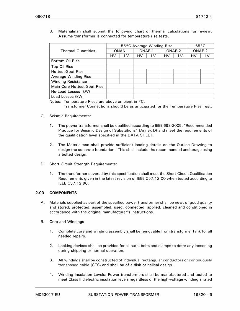
090718 81742.4
M063017-EU SUBSTATION POWER TRANSFORMER 16320 - 6
3. Materialman shall submit the following chart of thermal calculations for review.
Assume transformer is connected for temperature rise tests.
Thermal Quantities
55°C Average Winding Rise 65°C
ONAN ONAF-1 ONAF-2 ONAF-2
HV LV HV LV HV LV HV LV
Bottom Oil Rise
Top Oil Rise
Hottest-Spot Rise
Average Winding Rise
Winding Resistance
Main Core Hottest Spot Rise
No-Load Losses (kW)
Load Losses (kW)
Notes: Temperature Rises are above ambient in °C.
Transformer Connections should be as anticipated for the Temperature Rise Test.
C. Seismic Requirements:
1. The power transformer shall be qualified according to IEEE 693-2005, “Recommended
Practice for Seismic Design of Substations” (Annex D) and meet the requirements of
the qualification level specified in the DATA SHEET.
2. The Materialman shall provide sufficient loading details on the Outline Drawing to
design the concrete foundation. This shall include the recommended anchorage using
a bolted design.
D. Short Circuit Strength Requirements:
1. The transformer covered by this specification shall meet the Short-Circuit Qualification
Requirements given in the latest revision of IEEE C57.12.00 when tested according to
IEEE C57.12.90.
2.03 COMPONENTS
A. Materials supplied as part of the specified power transformer shall be new, of good quality
and stored, protected, assembled, used, connected, applied, cleaned and conditioned in
accordance with the original manufacturer’s instructions.
B. Core and Windings
1. Complete core and winding assembly shall be removable from transformer tank for all
needed repairs.
2. Locking devices shall be provided for all nuts, bolts and clamps to deter any loosening
during shipping or normal operation.
3. All windings shall be constructed of individual rectangular conductors or continuously
transposed cable (CTC) and shall be of a disk or helical design.
4. Winding Insulation Levels: Power transformers shall be manufactured and tested to
meet Class II dielectric insulation levels regardless of the high-voltage winding’s rated

090718 81742.4
M063017-EU SUBSTATION POWER TRANSFORMER 16320 - 7
voltage. Insulation levels for the phase and neutral end (where applicable) of each
winding are specified in the DATA SHEET.
5. The surface moisture content of the solid insulation at delivery, determined by the
dew point temperature of the shipping gas, shall be no greater than 0.5% moisture by
dry weight.
6. Additional requirements for windings associated with load tap changing are contained
in Section 16327 LOAD TAP CHANGER – EQUIPMENT AND CONTROLS when
specified in the DATA SHEET.
7. The core ground connection shall be external to the transformer tank. Individual core
ground leads shall be brought to the tank cover and exit the transformer tank, each
lead through a separate suitable bushing. Each lead and bushing shall be labeled to
indicate its origin. The Core Ground bushing(s) and ground connection(s) shall be
protected in an enclosure mounted on main tank’s cover.
The sides of the core ground enclosure shall be welded to cover of the main tank with
an overlapping enclosure cover that has a mineral oil-resistance gasket. The enclosure
cover shall either be hinged with a latch or secured with bolts. If secured with bolts,
a minimum of four bolts shall be used and the holes shall not result in a direct opening
into the enclosure. The enclosure cover shall be marked as ‘Core Ground’ and include
indication of its origin (e.g. Main, Series, PA). A detail of the core ground enclosure
shall be included on the outline drawing.
8. Autotransformer windings shall be fully distributed and designed for the control of
short-circuit forces for a fault at the transformer terminals.
9. If the stabilizing winding is brought out of the tank as an open delta (with two
bushings) and shorted and grounded externally, the Materialman shall provide:
a. A removable link between the bushings of suitably sized flexible braid or
laminated conductor. The selected link shall not damage the bushings due to
thermal expansion and contraction between -20°C and 105°C.
b. A two-hole grounding pad shall be welded to the tank adjacent to the bushings.
c. A suitable sized flexible lead between the two-hole pad and one of the bushings.
C. De-energized Tap Changer (DETC)
1. A hand operated, Category 2 de-energized tap changer fully compliant with C57.131-
2013 shall be provided for the H-winding.
2. Tap positions shall be as specified in the DATA SHEET.
3. The operating handle shall be located to allow personnel to change tap settings from
the ground. Tap setting indicator will be clearly visible to the operator. Provisions
shall be made to lock the operating handle.
4. The DETC shall have silver plating on the movable copper contacts and shall be
capable of passing a functional life test. The functional life test is conducted by
passing 2 times rated load current through the tap changer in a mineral oil bath of
130º C for 8 hours followed by 16 hours of cool-down with no load and no heat
supplied to the bath. A complete and valid test consists of 30 complete cycles.

090718 81742.4
M063017-EU SUBSTATION POWER TRANSFORMER 16320 - 8
Electrical resistance across the contacts is measured at the start and following each
thermal cycle. The test is considered successfully passed if the change in resistance
over 30 complete cycles is less than 25% and stability is reached at the completion of
the test.
D. Load Tap Changer
1. When specified in the DATA SHEET, the Materialman should refer to Section 16327
LOAD TAP CHANGER for the technical requirements for the Load Tap Changer’s
mechanism, controls and associated windings.
E. Tank
1. Tank shall be suitable for full vacuum filling and remain intact for static pressures
related to normal operations (e.g. energization, through faults).
2. The transformer cover shall be welded to tank and designed to allow removal and re-
installation. Cover shall include manholes to provide access to the interior.
3. Rupture Mitigation: Tank shall be designed to assure the predicted failure point will be
the top of the transformer to minimize the loss of insulating liquid. The energy
containment requirement is an Arc Energy of 2000 kJ (69 kV and below) and 4000 kJ
(above 69 kV).
4. Base shall be suitable for rolling or skidding in any direction.
5. When bushings are mounted on the cover, the tank design shall allow
removal/replacement of current transformers without removal of the tank cover.
6. Jacking pads shall be provided for lifting complete transformer assembly. Pulling eyes
for pulling complete transformer assembly shall also be provided.
F. Cooling Equipment
1. Cooling Fans
a. Automatically controlled fans shall give continuous forced cooling to deliver the
specified ONAF/ONAF capacity (at the specified ambient conditions and average
winding temperature rises) in the DATA SHEET.
b. All fan motors shall be totally enclosed and weatherproof; sealed and
permanently lubricated ball bearings; individually protected and rated for 55° C
ambient temperature, continuous operation.
c. All fan motors shall be connected in the circuit through weatherproof plug-in
fittings for easy removal of any fan without disturbing the others.
d. All cooling fans shall be equipped with OSHA-compliant guards over the fan
blades.
e. Cooling Fans shall be manufactured by Krenz & Company.
f. Status of each stage of cooling shall be provided for SCADA monitoring or as an

090718 81742.4
M063017-EU SUBSTATION POWER TRANSFORMER 16320 - 9
input to a transformer monitor.
g. The Cooling Control Circuit shall be provided as shown in Figure A.6 of C57.148
when a traditional winding temperature gauge is specified and a modified version
of Figure A.7 when a microprocessor-based transformer monitor is specified.
Figure A.7 shall be modified to include fan control by a traditional liquid
temperature indicator for instances when the microprocessor-based transformer
monitor has failed.
2. Radiators
a. Radiators shall be detachable with shut-off valves located on transformer tank.
b. Exterior surfaces of the radiators shall be galvanized or painted stainless steel.
c. Radiator drain and vent fittings shall be provided for all radiator units.
d. Oil tight covers shall be provided for use when radiators are detached.
e. Lifting eyes shall be provided with each detachable radiator/cooling unit.
G. Conduits
1. All circuits for forced-air cooling devices, temperature indication, alarms, current
transformers, and the power supply for cooling devices shall be installed in galvanized
steel Rigid Metal Conduit (RMC) securely fastened to the transformer. All RMC shall
be connected to cooling devices, instruments, shock-mounted cabinets (when
applicable) and other devices, with liquid proof flexible conduit. All conduit fittings
shall have weatherproof, mineral oil resistant gaskets. Insofar as practical, all
conduits shall be grouped in one general location. Conduits, conduit bodies and
conduit fittings shall meet applicable ANSI/NEMA/UL standards. There shall not be any
type of exposed wire or cable on the transformer except as approved by Engineer.
2. When conduit is cut and threaded, the length of the thread shall be one thread short
to prevent the conduit from butting inside the coupling.
3. Where junction boxes are used they shall be NEMA Type 4X, constructed of 0.080”
aluminum, with continuously welded seams, continuous hinged cover with a mineral
oil-resistance gasket, stainless steel clamps and screws. The junction box shall be E-
Box series AN4X, or as approved by Engineer.
4. Tank brace bands, which normally only contain atmospheric air, may be used in lieu of
conduit if adequate wiring supports and handholes (with covers) are provided.
5. Use of adequately designed and protected power cables in lieu of flexible conduit for
connection to cooling fan motors is acceptable.
H. Grounding
1. Tank Grounding – Two-hole grounding pads shall be welded on all four corners of the
tank, 6 inches above the base, for grounding of transformer with bolt type connectors
for connection to 1/0 AWG to 4/0 AWG stranded copper conductor. The connectors
shall be included.
090718 81742.4
M063017-EU SUBSTATION POWER TRANSFORMER 16320 - 10
2. Neutral Grounding - When the neutral bushing’s mounting location is not specified to
be on the Sidewall, clamps suitable for one vertically mounted 2 inch Schedule 80
PVC conduit (Owner supplied) shall be furnished. The clamps shall be equally spaced
(36 inch minimum interval) and below each neutral bushing.
3. Air terminal chamber (when specified in DATA SHEET) shall be equipped with
24”x2”x0.375” copper ground bus. Ground bus shall be drilled at one end for the
installation for one (1) 2-hole NEMA pad. The Materialman shall provide a 4/0 copper
conductor from the NEMA 2-hole pad to a grounding pad located on the tank wall near
the ATC. Ground bus shall be located to provide unimpeded installation of power cable
shield ground conductors and surge arrester grounding. The Materialman shall provide
and install arrester grounding jumpers and required connectors.
4. Surge Arrester Grounding.
a. When the phase bushings are cover-mounted, two-hole grounding pads shall be
welded at the top of the transformer tank walls for grounding the surge arresters.
Three of these pads shall be located approximately three inches (3") from the top
of tank in Segment 1. Three additional pads shall be located approximately three
inches (3") from the top of tank in Segment 3 (when an ATC is not specified).
b. When an ATC is specified, a grounding pad for each surge arrester shall be
provided inside ATC and connected to the ATC’s ground bus with a 4/0 copper
conductor. The connectors shall be included.
c. Materialman shall also provide a bolt type connector (conductor range 1/0 AWG
to 4/0 AWG kcmil) for each grounding pad to connect the surge arresters’ ground
terminal to with a stranded copper conductor.
5. Power Cable Shield Grounding – When an ATC is specified in the DATA SHEET
6. Control Cabinet Grounding - All control wiring ground connections shall be at the
control cabinet’s ground bus bar.
I. Insulating Liquid Preservation System
1. The transformer shall be equipped with a positive pressure, inert gas preservation
system consisting of the following:
a. A standard, commercially available supply cylinder (Linde Size K or approved
equivalent) with control valve. Equipment shall be compatible with US-DOT
Standards.
b. Three stage pressure reducers.
c. Pressure relief valve.
d. Run-fill valve.
e. Oil sump.
f. Gauges indicating transformer tank pressure and supply cylinder pressure.
g. Pressure switches indicating low tank pressure, high tank pressure and low
cylinder pressure. All alarm contacts shall be wired to terminal blocks located in
main control cabinet mounted on main body of transformers unit for connection
to external alarm circuits. When Form C contacts are provided for alarms, the
Materialman shall indicate on the schematic drawings the contact position in the

090718 81742.4
M063017-EU SUBSTATION POWER TRANSFORMER 16320 - 11
normal operating condition.
h. All instruments and gauges shall be scaled in °C for temperature and pounds per
square inch (psi) for pressure. Scale may include SI (metric) units.
i. Piping and valves necessary to control the flow of gas to and from the
transformer tank.
j. The complete preservation system, including inert gas cylinder, shall be enclosed
in a weatherproof cabinet mounted on the main body of the transformer.
J. Insulating Liquids
1. Acceptable Insulating Liquids are specified in the DATA SHEET.
2. All insulating liquid supplied with the transformer shall be tested for polychlorinated
biphenyls (PCBs) by ASTM D4059 or EPA 8082 and shall contain no detectable levels
(<2.0 ppm) of PCBs.
3. Mineral oil, when specified, shall be unused and meet all requirements of ASTM
D3487 and testing limits of ANSI/IEEE C57.106 for new oil. Mineral oil also shall
include DBPC (2-6 ditertiary butyl para-cresol) as an inhibitor and state such on the
nameplate.
4. Natural ester liquids, when specified, shall be unused and meet all the requirements of
ASTM D6871 - 03 and C57.147 for new liquids. Envirotemp® FR3 manufactured by
Cargill and Biotemp® manufactured by ABB are approved for use.
5. The Materialman shall demonstrate the insulating liquid is non-corrosive when tested
according to ASTM D1275. Results of this modified test shall be included with the
Materialman’s Field Test Report.
K. Bushings
1. Bushings rated above 110 kV BIL shall be oil filled and shall meet all requirements of
IEEE C57.19.00 and C57.19.01. Nameplate shall state that oil has no detectable
levels of PCBs (<2.0 ppm).
2. Porcelain parts of each bushing shall be of one-piece construction.
3. All mounting bolts, studs, nuts and lockwashers associated with bushings shall be
stainless steel. The Materialman’s application should address potential galling.
4. All dimensions for bushings shall be shown on submittal drawings.
5. Bushing ratings and location shall be as shown in the DATA SHEET.
6. Bushing terminals shall be as specified in the DATA SHEET.
7. When an Air Terminal Chamber (ATC) is specified on DATA SHEET, the phase
bushings shall be inside the ATC while the neutral bushing shall be on the cover.
L. Surge Arresters
1. Surge arresters shall be installed for each winding or as shown in the DATA SHEET
and shall meet all requirements of IEEE Standard C62.11.
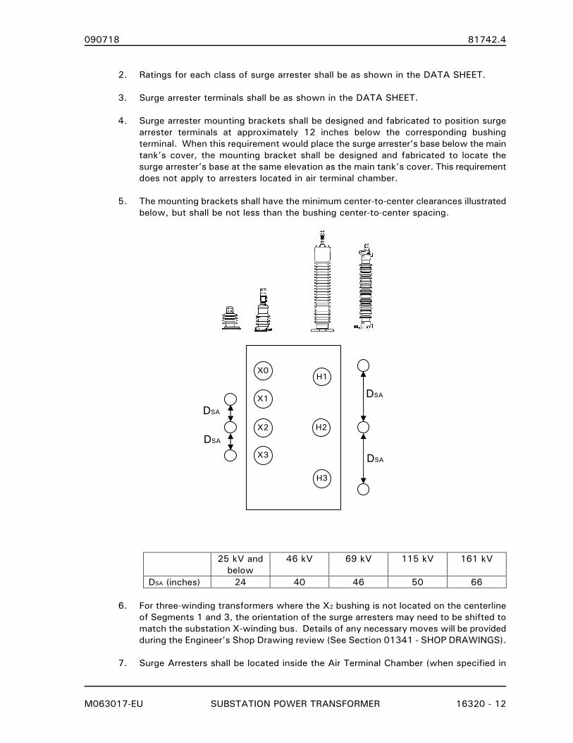
090718 81742.4
M063017-EU SUBSTATION POWER TRANSFORMER 16320 - 12
2. Ratings for each class of surge arrester shall be as shown in the DATA SHEET.
3. Surge arrester terminals shall be as shown in the DATA SHEET.
4. Surge arrester mounting brackets shall be designed and fabricated to position surge
arrester terminals at approximately 12 inches below the corresponding bushing
terminal. When this requirement would place the surge arrester’s base below the main
tank’s cover, the mounting bracket shall be designed and fabricated to locate the
surge arrester’s base at the same elevation as the main tank’s cover. This requirement
does not apply to arresters located in air terminal chamber.
5. The mounting brackets shall have the minimum center-to-center clearances illustrated
below, but shall be not less than the bushing center-to-center spacing.
25 kV and
below
46 kV 69 kV 115 kV 161 kV
DSA (inches) 24 40 46 50 66
6. For three-winding transformers where the X2 bushing is not located on the centerline
of Segments 1 and 3, the orientation of the surge arresters may need to be shifted to
match the substation X-winding bus. Details of any necessary moves will be provided
during the Engineer’s Shop Drawing review (See Section 01341 - SHOP DRAWINGS).
7. Surge Arresters shall be located inside the Air Terminal Chamber (when specified in
H3
H1
H2
X3
X2
X1
X0
DSA
DSA
DSA
DSA
090718 81742.4
M063017-EU SUBSTATION POWER TRANSFORMER 16320 - 13
DATA SHEET).
M. Current Transformers
1. All relay class bushing current transformers (BCT) shall be 5 lead, multi-ratio type with
fully distributed windings with a minimum continuous current rating factor of 2.0.
Ratio, Accuracy Class and location shall be as indicated in the DATA SHEET.
2. Revenue metering bushing current transformers, when specified in the DATA SHEET,
shall be provided with the Ratio, Accuracy Class and location indicated and with the
following additional requirements:
a. Four (4) copies of the Certified Test Report (CTR) shall be provided for each
metering BCT supplied. Tests on prototypes or similar units are not acceptable.
b. The CTR shall include a ratio and phase-angle test on each ratio of each CT.
Tests shall be made at 10 percent and 100 percent current for each burden and
accuracy class specified.
c. Revenue metering current transformers shall have a minimum continuous current
factor of 2.0.
3. Bushing Current Transformer Wiring:
a. All bushing current transformer leads shall be pre-wired to shorting type terminal
blocks in the main control cabinet. From these terminal blocks, leads will be pre-
wired to GE 6-pole PK-2 test blocks. The ratio and connection (wye or delta) will
be formed at the shorting type terminal blocks. Therefore, for a three-phase
transformer, one 6-pole PK-2 block will be required for each set of three-phase
BCTs. A 4-pole PK-2 test block should be used for BCT circuit that is not a three-
phase set.
b. Incoming BCT wiring to the PK-2 test blocks shall be terminated on the bottom of
the block and the outgoing (relay/meter) wiring shall be terminated on the top of
the block. For three-phase BCT sets, the H1 or X1 polarity lead shall be on left as
viewed from the front of the panel.
c. Wiring from PK-2 blocks to terminal blocks for connection to external circuits
shall be provided.
d. The shorting type terminal blocks shall be marked to identify CT ratio
connections.
e. An example showing the specified three-phase BCT circuit is shown below:
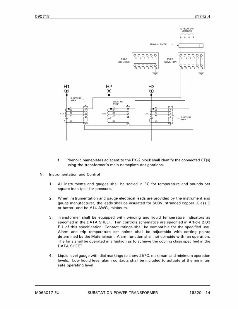
090718 81742.4
M063017-EU SUBSTATION POWER TRANSFORMER 16320 - 14
H3H2H1
X1
X2
X3
X4
X5
CTC
X1
X2
X3
X4
X5
CTB
X1
X2
X3
X4
X5
CTA
1357911
24681012
TO RELAY'S OR
METERING
SHORTING
STRIP
SHORTING
STRIPSHORTING
STRIP
TERMINAL BLOCK
1357911
24681012
PK2-3
COVER ON
PK2-3
COVER OFF
f. Phenolic nameplates adjacent to the PK-2 block shall identify the connected CT(s)
using the transformer’s main nameplate designations.
N. Instrumentation and Control
1. All instruments and gauges shall be scaled in °C for temperature and pounds per
square inch (psi) for pressure.
2. When instrumentation and gauge electrical leads are provided by the instrument and
gauge manufacturer, the leads shall be insulated for 600V, stranded copper (Class C
or better) and be #14 AWG, minimum.
3. Transformer shall be equipped with winding and liquid temperature indicators as
specified in the DATA SHEET. Fan controls schematics are specified in Article 2.03
F.1 of this specification. Contact ratings shall be compatible for the specified use.
Alarm and trip temperature set points shall be adjustable with setting points
determined by the Materialman. Alarm function shall not coincide with fan operation.
The fans shall be operated in a fashion as to achieve the cooling class specified in the
DATA SHEET.
4. Liquid level gauge with dial markings to show 25°C, maximum and minimum operation
levels. Low liquid level alarm contacts shall be included to actuate at the minimum
safe operating level.

090718 81742.4
M063017-EU SUBSTATION POWER TRANSFORMER 16320 - 15
5. Pressure-Vacuum gauge with scale range of plus or minus 10 PSI. This may be
integrally part of the insulating liquid preservation system.
6. Sudden pressure relay (63) ABB part number 8524A42G02. The 63 relay shall be
connected to an auxiliary seal-in relay (63X), Qualitrol model 909-200-01 or 909-210-
01. The seal-in relay’s Form C alarm contacts shall be used for annunciation. The
seal-in relay’s Form A tripping contact shall be used in the protection scheme.
7. Pressure relief device mechanically operated with signal indicator visible from the
ground. One (1) set of isolated, Form C alarm contacts shall be provided for remote
annunciation.
8. Auxiliary relays used to provide the required alarm and trip output contacts shall be
mounted such that vibration from other devices will not cause a misoperation of the
auxiliary relays. Auxiliary relays shall not be mounted adjacent to contactors used for
fan control or auxiliary power to transformer. The Materialman shall illustrate
mounting and shock isolation methods on shop drawings.
9. Leads for alarm and trip circuits shall be pre-wired to terminal blocks for external
connection. These terminal blocks shall be marked to identify leads and shall be
mounted in the main control cabinet.
10. Contacts identified in the DATA SHEET as Trip Contacts shall be rated as specified in
C37.90-1989 (5A continuous, 30A for 200ms).
O. Control Cabinet
1. Control Cabinet shall meet the specifications outlined IEEE C57.148. Optional items
and specifications that are different from C57.148 are outlined here or tabulated in the
DATA SHEET in the format shown in Annex B of C57.148.
2. All devices within the control cabinet shall have nameplates attached with screws
suitable for the application or as approved by the Engineer. The nameplates shall be
black phenolic with white core. The Material shall submit a nameplate schedule for the
Engineer’s approval.
3. Control cabinet doors shall capable of being opened and secured at a minimum of a
105 degree position. Swing panels shall be opened and secured at a minimum of a 90
degree position. Materialman shall detail on the Control Cabinet Layout drawings both
the door(s) and swing panel(s) in the opened and secured position. This detail shall
include items mounted on the inside of the cabinet door(s) (e.g. instruction manual
pockets, latching mechanism) and items on the swing panel that extend beyond
surface (e.g. test switches, instrumentation).
P. Wiring
1. All wiring shall have pressure grip solderless lugs of the uninsulated ring-type
terminators. Spade lugs will not be permitted.
2. Suitable grommets and cable/conductor protection shall be used at locations of
cable/conductor contact with edges, corners and openings of the control cabinet.
3. No splices are allowed (except in CT outlet or junction box) within the control, current
090718 81742.4
M063017-EU SUBSTATION POWER TRANSFORMER 16320 - 16
transformer, or instrument wiring leads. All connections shall utilize terminal blocks
located in the control cabinet or junction boxes. Splices or ring-type terminals are
allowed at the Bushing CT outlet or junction box.
4. For easy access and permit an orderly arrangement of all leads terminating on each
block. Wiring associated with one circuit, along with spare conductors shall be
connected on adjacent terminals.
5. All alarm and trip contacts (not specified to be wired to an electronic transformer
monitor) shall be wired to terminal blocks located in the main control cabinet, mounted
on the main body of the transformer unit, for connection to external alarm and trip
circuits.
6. For every ten (10) used terminals, two (2) spare terminals shall be provided.
Q. Supply Voltages
1. Supply Voltages furnished by the Owner are specified in the DATA SHEET.
R. Nameplates
1. Nameplate shall contain all information for Nameplate C, set forth in IEEE Standard
C57.12.00 and the following information:
a. State the insulating liquid is inhibited.
b. When appropriate, statement that windings are fully insulated (not graded or
reduced insulation level).
c. State the maximum loading at an average ambient of 0°C.
2. A seismic qualification identification plate shall be designed and attached to the
equipment to last its service life. The plate shall follow the format show in IEEE 693-
2005 A.8. The seismic qualification identification plate shall be mounted below the
transformer’s main nameplate.
PART 3. EXECUTION
3.01 FABRICATION
A. Minimum external clearance between live parts of different phases shall be 24 inches for
25 kV and below, 30 inches for 46 kV and 36 inches for 69 kV. These clearances shall
also be maintained between the neutral bushing’s stud and the live parts of the closest
phase.
B. Bushing spacing shall not compromise bushing flashover characteristics. Bushing located in
air terminal chamber shall be spaced to allow installation of specified power cables with
adequate working space.
C. Center of gravity for shipping shall be identified on all sides that are visible without
obstruction when the transformer is assembled for shipping. The center of gravity for
operations shall be identified on all sides visible without obstruction when the transformer
is completely assembled. In no case shall these markings be on less than two sides.
090718 81742.4
M063017-EU SUBSTATION POWER TRANSFORMER 16320 - 17
D. All bolts, studs, nuts and lockwashers used to mount radiators, fans, cabinets, junction
boxes, accessories and conduit shall be stainless steel.
E. Galvanized RMC systems shall be installed as detailed in NECA 101 – Standard for
Installing Steel Conduits (Rigid, IMC EMT) including:
1. Threading shall be one thread short of the chase to prevent butting of the conduit in a
coupling allowing the coupling to cover all of the conduit threads when tightened.
2. Threads shall be protected with an electrically-conductive, corrosion resistant
compound (UL category “FOIZ”) or a zinc-rich paint.
3. Conduit Bodies and Fittings shall comply with NEMA FB2.10 - Selection and
Installation Guidelines For Fittings for Use With Non-Flexible Metallic Conduit or Tubing
(Rigid Metal Conduit, Intermediate Metal Conduit, and Electrical Metallic Tubing).
F. Air Terminal Chamber (ATC) (when specified in the DATA SHEET)
1. The ATC shall be weatherproof and have hinged access doors complete with handle-
type, 3 point, latching mechanism and provisions for padlocking in close position. The
ATC shall be furnished with stainless steel bug screens and fine mesh filters at all
ventilating openings. Louvers shall be installed over these openings to prevent rain
from entering the cabinet
2. The bottom plate of the ATC shall have a removable, gasketed blank face to allow
field drilling for the cable entrance conduits. The blank face shall be sized to
accommodate the cable entrance conduits specified in the DATA SHEET.
3. The ATC shall be sized to accommodate the size and number of cables specified in the
DATA SHEET. Consideration shall be given to the cable’s minimum bending radius (20
times cable diameter) and the cable weight applied to the bushing terminal. Bushing
terminals shall be braced, if necessary, to support the cable’s weight and forces
applied by cable bending. The Materialman shall supply all necessary insulators and
supports to accomplish support of the bushing terminals. If the Materialman proposes
to use the bushings to support all cable weight and bending forces, information
necessary to substantiate this practice shall be provided.
4. Surge Arresters shall be mounted in the air terminal chamber adjacent to the X-
Winding bushings in a location that will not interfere with power cable installation.
Materialman to provide and install surge arrester to bushing terminal jumper and
required connectors. Arrester jumper connection at the bushing terminal shall not
interfere with phase conductor installation in any way. Jumper shall be minimum No.2
copper.
5. Minimum Clearances inside the ATC will be as specified in IEEE C57.12.00 Table 11
and NEMA TR-1. For convenience, these values are is partially reproduced below:
BIL (kV) Minimum Clearances (inches)
Live Parts to Ground Live Parts Phase to Phase
110 6 6-1/2
150 8 9

090718 81742.4
M063017-EU SUBSTATION POWER TRANSFORMER 16320 - 18
G. Painting/Finishing
1. All steel parts, except galvanized or stainless (if used), shall have a coating system
that meets or exceeds the coating system requirements of ANSI C57.12.28 –1999
(including salt spray test).
2. The complete transformer shall be painted the color specified in the DATA SHEET. The
paint film shall be uniform in color and free from blisters, sags, flaking and peeling.
Galvanized and stainless steel surfaces (e.g., conduits, etc.) shall not be painted. Use
of other colors, such as “silver” to mimic galvanized parts is prohibited.
3. Exterior surfaces of the radiators shall be galvanized or painted stainless steel. The
Materialman’s thermal calculations shall allow for the lower emissivity of the radiator’s
surface finish. The interior radiator surfaces shall not be painted, but shall be flushed
with mineral oil and sealed to protect against rust before final installation.
4. Interior of tank, control and accessory cabinets shall be painted white semi-gloss.
Surfaces that are inaccessible after fabrication shall be protected for the life of the
unit.
5. Surfaces composed of corrosion-resistant metal or galvanized steel (including
aluminum and stainless steel junction boxes; conduit bodies and fittings) shall be
appropriately masked or covered during the painting process.
6. Painting of Galvanized RMC is only allowed when the Materialman’s coating system is
specified as compatible with galvanized steel by the paint manufacturer and proposed
coating system is approved in advance by the Engineer.
7. Galvanized surfaces shall comply with ASTM A123/A123M-02 Standard Specification
for Zinc (Hot-Dip Galvanized) Coatings on Iron and Steel Products. The minimum
acceptable coating grade shall be 100.
8. Two (2) one-quart containers of touch-up paint, equivalent in all respects to the
original paint applied during fabrication, shall be supplied with the unit upon delivery.
Instructions for applying paint shall be supplied.
3.02 FACTORY TESTS
A. The Owner shall be notified two weeks prior to performance of factory transformer testing
to permit Owner’s representative to observe the tests.
B. All factory tests shall be completed with the type of insulating liquid being provided for
field installation. Mixing different types of insulating liquids is not permitted.
C. All transformers shall be tested as a Class II transformer in accordance with the latest
revision of IEEE C57.12.00, C57.12.90, and C57.98. These tests shall be made for every
unit provided under this specification.
D. Required Tests: The Materialman shall conduct all tests designated as routine for Class II
power transformers in the latest revision of IEEE C57.12.00. Complete testing shall be
conducted on all units of the design.
1. If the stabilizing winding is brought out of the tank as an open delta (with two
090718 81742.4
M063017-EU SUBSTATION POWER TRANSFORMER 16320 - 19
bushings) and shorted and grounded externally, the winding resistance of the
stabilizing winding shall be measured between the two bushings with the external link
removed.
2. Insulation Resistance between windings, each winding to ground and core(s) to
ground. Any values less than 1000 Megohms shall be investigated and justified to the
Engineer.
3. Insulation Power Factor/Dielectric Loss Test.
a. Power Factor/Dielectric Loss on all windings.
b. Power Factor/Dielectric Loss (or hot collar watts-loss) on all bushings.
4. Single Phase Excitation shall be performed on all of the de-energized tap positions of
the high voltage winding. Additionally for transformers with a LTC, the single phase
excitation shall also be performed with the high voltage winding on the nominal tap
and the LTC in every position from 1L to 16R, inclusive.
5. Load Loss and Impedance Voltage Tests. For units with LTCs, the Materialman shall
complete the additional tests specified in Table 18 of C57.12.00 for each unit. The
Materialman shall also complete a load loss and impedance voltage test at 15 Raise to
verify compliance with guaranteed losses.
6. Temperature Rise. Temperature rise test shall be performed as described by IEEE
C57.12.90 on each unit provided under this specification.
a. When a microprocessor-based transformer monitor is specified in the DATA
SHEET, the transformer monitor shall be powered up and receiving current from
the source CTs. Additionally, the transformer monitor shall be programed as
approved by the Engineer except that data logging/signal profile sampling rate
shall be 5 minutes. When the temperature rise tests are complete, the recorded
data shall be retrieved from the transformer monitor and the data file sent with
the certified test reports.
b. Data from the temperature rise tests included on the certified test report shall
include the data outlined in IEEE C57.91 Clause 4.4 items a) through k) including
the conditions (load ambient temperature, tap, etc.) under which measurements
for a) through g) were made.
c. The certified test report shall include the cold-resistance measurements made
prior to loading and hot-resistance measurements made after shut down for each
load level. The first hot-resistance measurement shall be made within four
minutes of shut down. Hot-resistance measurements shall be tabulated and
graphed. Graphed measurements shall also show the cooling curve fitted to the
measurements and extrapolated to shut down. Additionally, the winding and oil
time constants shall be calculated and included in the certified test report.
d. Time, in hours, required to complete the temperature rise test shall be included
on the certified test report.
e. Materialman shall state in the certified test report the transformer’s maximum
continuous capacity in MVA at an average ambient of 0°C. The maximum
capacity shall be at the combination of connections and taps that give the

090718 81742.4
M063017-EU SUBSTATION POWER TRANSFORMER 16320 - 20
highest average winding temperature rise. Materialman shall note requirement in
Article 2.02 Paragraph B that ancillary devices (e.g., LTC mechanism, DETC,
bushing, etc.) shall not limit loading.
7. Audible Sound Emissions. Audible sound tests shall performed as described by IEEE
C57.12.90 on each unit provided under this specification as required in the DATA
SHEET.
a. DETC and LTC (where applicable) tap positions shall be selected to produce the
highest sound level.
8. Impulse Test.
a. Impulse testing shall be as described in IEEE C57.12.90.
b. Front of wave test will not be required.
9. Applied-Voltage Test shall be completed using the test values in Table 4 of IEEE
C57.12.00-2010.
a. If the stabilizing winding is brought out of the tank as an open delta (with two
bushings) and shorted and grounded externally, the applied-voltage test shall be
performed on the stabilizing winding at a test level corresponding to winding’s
nominal phase-to-phase voltage.
10. Induced-Voltage Test shall be completed using the test values in Table 4 of IEEE
C57.12.00-2010.
a. During the induced-voltage test, the pressure inside the transformer tank shall not
be artificially increased by more than 0.5 lbf/in2.
b. If the stabilizing winding is brought out of the tank as an open delta (with two
bushings) and shorted and grounded externally, the corner of the stabilizing
winding should be grounded during the induced-voltage test.
c. Partial Discharge test shall be acceptable if the Partial Discharge does not exceed
250 pC or 100 µV. Additionally, during the one hour test period, levels do not
increase by more the 50 pC or 30 µV. Background levels shall be less than 100
pC.
11. Dissolved Gas-In-Oil.
a. At a minimum, samples will be drawn prior to transformer testing, before
temperature rise testing, after the completion of temperature rise testing (no
more than 6 hours after load is shut down) and at the completion of dielectric
testing.
b. Samples shall be drawn in accordance with ASTM D923 in a container suitable
for DGA analysis.
c. Gas generation rates shown below will be used to determine if the transformer
passed or failed.
Gas Generation Rates (ppm/hour)
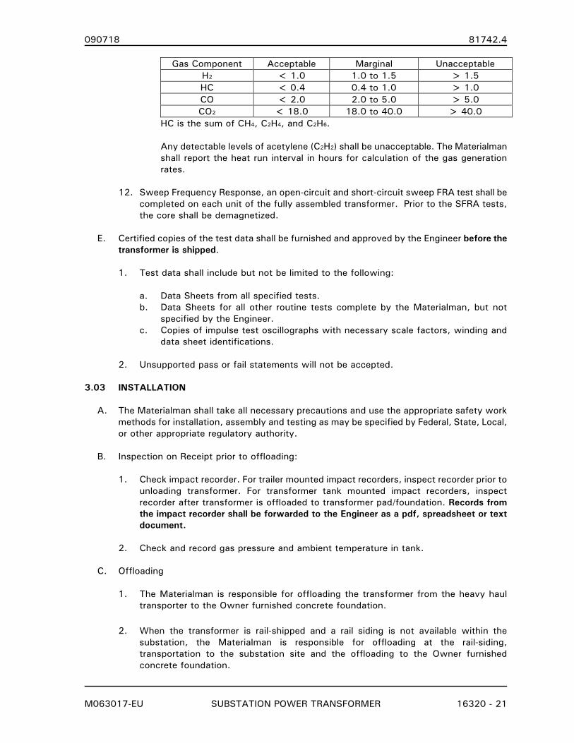
090718 81742.4
M063017-EU SUBSTATION POWER TRANSFORMER 16320 - 21
Gas Component Acceptable Marginal Unacceptable
H2 < 1.0 1.0 to 1.5 > 1.5
HC < 0.4 0.4 to 1.0 > 1.0
CO < 2.0 2.0 to 5.0 > 5.0
CO2 < 18.0 18.0 to 40.0 > 40.0
HC is the sum of CH4, C2H4, and C2H6.
Any detectable levels of acetylene (C2H2) shall be unacceptable. The Materialman
shall report the heat run interval in hours for calculation of the gas generation
rates.
12. Sweep Frequency Response, an open-circuit and short-circuit sweep FRA test shall be
completed on each unit of the fully assembled transformer. Prior to the SFRA tests,
the core shall be demagnetized.
E. Certified copies of the test data shall be furnished and approved by the Engineer before the
transformer is shipped.
1. Test data shall include but not be limited to the following:
a. Data Sheets from all specified tests.
b. Data Sheets for all other routine tests complete by the Materialman, but not
specified by the Engineer.
c. Copies of impulse test oscillographs with necessary scale factors, winding and
data sheet identifications.
2. Unsupported pass or fail statements will not be accepted.
3.03 INSTALLATION
A. The Materialman shall take all necessary precautions and use the appropriate safety work
methods for installation, assembly and testing as may be specified by Federal, State, Local,
or other appropriate regulatory authority.
B. Inspection on Receipt prior to offloading:
1. Check impact recorder. For trailer mounted impact recorders, inspect recorder prior to
unloading transformer. For transformer tank mounted impact recorders, inspect
recorder after transformer is offloaded to transformer pad/foundation. Records from
the impact recorder shall be forwarded to the Engineer as a pdf, spreadsheet or text
document.
2. Check and record gas pressure and ambient temperature in tank.
C. Offloading
1. The Materialman is responsible for offloading the transformer from the heavy haul
transporter to the Owner furnished concrete foundation.
2. When the transformer is rail-shipped and a rail siding is not available within the
substation, the Materialman is responsible for offloading at the rail-siding,
transportation to the substation site and the offloading to the Owner furnished
concrete foundation.

090718 81742.4
M063017-EU SUBSTATION POWER TRANSFORMER 16320 - 22
D. External Inspection after offloading
1. Check for evidence of hits, scrapes, and abrasions.
2. Check for damage to components (e.g., bushings, gauges, conduits and valves).
3. Record the condition of the paint.
4. Check that external parts have not become loose and that external compartments
remain sealed.
5. Check inside the control cabinets for visible damage, loose parts, foreign matter and
moisture accumulation.
6. For liquid-filled shipping, check for signs of leaks.
E. Internal Inspection after offloading
1. If receiving gas pressure (units shipped gas-filled) are neither positive nor negative,
test the dew point temperature of the shipping gas. If dew point temperature indicates
the solid insulation surface moisture content is above 0.5%, the insulation must be
dried until this requirement is met. The Materialman shall provide the installation
contractor data to correlate moisture content with dew point temperature.
2. The Materialman shall follow OSHA confined space practices and procedures.
3. The transformer shall not be opened when the relative humidity exceeds 60 percent,
when precipitation is threatening or when the interior of the transformer is appreciably
cooler than the ambient.
4. Dry air with a Dew Point of -60°F or better shall be continuously supplied while the
transformer is opened.
5. Record time the tank seal is broken and reestablished. The amount of time the tank is
open to the atmosphere should be limited to 2 hours.
6. The Internal Inspection will include, as a minimum, removing of all shipping blocks and
provide an examination of core, windings, leads and support structures.
7. All tools shall be accounted for after the internal inspection.
F. Assembly of Fittings
1. Materialman is responsible for supplying all tools necessary for the final assembly of
the transformer. This includes a crane, as needed, to install bushing and radiators.
2. The transformer shall not be opened for final assembly when the relative humidity
exceeds 60 percent, when precipitation is threatening or when the interior of the
transformer is appreciably cooler than the ambient.
3. Bushings and Radiators shall be installed according to transformer and bushing
manufacturers’ recommendations. This includes tightening the mounting bolts to the
090718 81742.4
M063017-EU SUBSTATION POWER TRANSFORMER 16320 - 23
bushing manufacturer’s recommendations.
4. Damage, touch up and replacement. Care should be used to avoid scratching painted
or galvanized surfaces.
a. If primer is exposed and intact, lightly sand the damaged paint to smooth the
rough edges. Next, restore the original thickness with a brush or spray. The paint
used for the finish coat shall be the same color and quality as the original.
b. If metal becomes exposed, the area must be sanded down to blend the damaged
area into the undamaged paint surface. Wipe the area with a commercial safety
solvent and then dry. Brush or spray the area with a primer compatible with the
surface and finish coat. Apply a finish coat using paint of the same color and
quality as the original.
c. Galvanized surfaces that are damaged during shipping or installation shall be
repaired in accordance with ASTM A780-01 Standard Practice for Repair of
Damaged and Uncoated Areas of Hot-Dip Galvanized Coatings. Galvanizing repair
paint shall have 95 percent zinc by weight. Touch-up of galvanized surfaces with
aerosol spray, silver paint, bright paint, Brite Paint, or aluminum paints is not
acceptable.
d. Radiators with holes or dents shall be replaced unless the Engineer has approved
a repair plan in advance.
e. Bushings with chipped or cracked porcelain shall be replaced.
G. Vacuum Filling
1. In cases where the insulating liquid is shipped separately from the transformer, the
Materialman shall furnish all necessary equipment, parts, and labor to vacuum fill the
transformer after installation in the field, as outlined in Materialman’s installation
procedures and directives.
2. The insulating liquid shall have the following characteristics before being allowed to
enter the transformer:
a. Liquid temperature shall be between 60°C and 80°C.
b. Water content (ASTM D1533) shall not exceed 10 ppm for mineral oil or 150
ppm for natural ester liquids.
c. Total dissolved combustible gas content shall not exceed 0.5 percent.
d. Dielectric Strength shall exceed 30 kV (ASTM D1816 – 0.04 inch gap).
3.04 FIELD TESTING AFTER INSTALLATION
A. After installation at the specified location, the following tests shall be performed by the
Materialman:
1. Operational checks of all indicating and control devices, fans, and LTC controls (where
applicable).
2. Insulation Resistance between windings, each winding to ground and core(s) to
ground.
3. Power Factor/Dielectric Loss on all windings.

090718 81742.4
M063017-EU SUBSTATION POWER TRANSFORMER 16320 - 24
4. Power Factor/Dielectric Loss (or hot collar watts-loss) on all bushings.
5. Single Phase Excitation shall be performed on all of the de-energized tap positions of
the high voltage winding. Additionally for transformers with a LTC, the single phase
excitation shall also be performed with the high voltage winding on the nominal tap
and the LTC in every position from 1L to 16R, inclusive.
6. Transformer Turns Ratio (TTR) shall be performed for all factory test tap combinations
specified in C57.12.00.
7. Winding Resistance Test shall be made on all windings and at all tap positions
(corrected to 75C).
a. If the stabilizing winding is brought out of the tank as an open delta (with two
bushings) and shorted and grounded externally, the winding resistance of the
stabilizing winding shall be measured between the two bushings with the external
link removed.
8. Insulating liquid samples shall be retrieved in a suitable container under the provisions
in ASTM D923 and shall have the following testing conducted:
a. Dissolved Gas-in-Oil, D3612.
b. Dielectric Strength, D1816 (0.04 inch gap).
c. Power Factor at 25C and 100C, D924.
d. Interfacial Tension, D971.
e. Neutralization Number, D974.
f. Moisture Content, D1533.
g. Oxidation inhibitor content, D2668 (mineral oil only).
h. Fire point, ASTM D92 (natural esters only).
i. Kinematic Viscosity, D445 (natural esters only).
j. PCB Content, D4059.
k. Corrosive Sulfur, D1275 (mineral oil only)..
9. Bushing Current Transformers shall be tested in accordance with IEEE C57.13.1 as
follows:
a. Turns ratio.
b. Insulation Resistance.
c. Polarity.
d. Excitation.
B. The Owner shall use the follow acceptance criteria to determine the suitability of the
Materialman’s installation:
1. Insulation resistance shall not be less than 100 megohm for the power transformer
winding and core measurements.
2. Power factor of the windings shall not exceed 0.5 percent corrected to 20°C.
3. Power factor and capacitances of the bushings shall not exceed the nameplate by
more than 10.0 percent.
4. Turns ratio shall be within 0.5% of the calculated value.

090718 81742.4
M063017-EU SUBSTATION POWER TRANSFORMER 16320 - 25
5. Winding Resistance, after temperature correction, shall be within 1.0 percent of the
factory test values.
6. Mineral oil test results shall meet the criteria in C57.106 for new mineral oil received
in new equipment for the voltage class >69 - <230 kV (regardless of the
transformer’s highest voltage). Natural ester liquid test results shall meet the
requirements of same voltage class in C57.147. Total dissolved gases shall be less
than 0.5 percent and PCB content shall be less than 2 ppm.
7. Bushing current transformer ratio and excitation tests shall not deviate significantly
from the manufacturer’s published data. Polarity shall match the power transformer’s
nameplate. Insulation resistance shall not be less than 100 megohms.
C. Materialman shall provide comparison of installation test data and data from factory tests.
Deviation from factory test results shall be explained in writing to the Engineer.
3.05 FIELD TEST REPORT
A. The Materialman shall provide a blank copy of the Field Report as a part of the submittal
procedure. The contents of this Field Report shall require the Engineer’s approval.
B. The Materialman shall report to the Engineer the conditions found during the external
inspection of the transformer. This should include the following:
1. Maximum impact.
2. Number of Zone 3 impacts.
3. Number of one-G impacts.
4. Tank Pressure
5. Ambient Temperature.
6. Insulation Temperature and method for determining this value.
7. Dew Point of Shipping Gas.
8. Results of core ground insulation resistance test(s).
In addition, a statement of the overall condition of the tank and accessories noting any
damage, leaks or rust shall be included.
C. The Materialman shall report to the Engineer the conditions found during the internal
inspection of the transformer including:
1. Ambient Temperature.
2. Relative Humidity.
3. Time the transformer is opened.
4. Time the transformer is sealed.
In addition, a statement on the condition of the transformer’s internal components noting
any damage or rust shall be included.
D. When the transformer is vacuum filled in the field, the Materialman shall provide the
Engineer a report detailing the filling process with hourly log of the procedure.
E. The Materialman shall report to the Engineer the results of all tests performed after the
installation.

090718 81742.4
M063017-EU SUBSTATION POWER TRANSFORMER 16320 - 26
END OF SECTION
090718 81742.4
M063017-EU DATA SHEET - SUBSTATION POWER TRANSFORMER 16320D - 1
SECTION 16320D
DATA SHEET
SUBSTATION POWER TRANSFORMER
PART 1. GENERAL
1.01 SECTION INCLUDES
A. This Data Sheet includes the design and material data information for the fabrication of the
Substation Power Transformer(s), as specified in Section 16320 - SUBSTATION POWER
TRANSFORMER. This includes two and three winding transformers as well as
autotransformers.
1.02 SERVICE CONDITIONS:
A. The maximum ambient temperature will not exceed 40°C and the 24-hour average ambient
temperature will not exceed 30°C. Additionally, the transformer(s) will not be subjected to
liquid temperatures below -20°C.
B. The transformer(s) will be installed outdoors at an approximate elevation of 600 feet above
mean sea level.
C. The transformer(s) secondary load current will not exceed a harmonic factor of 0.05 per
unit.
D. The transformer(s) will be used as step-down substation power transformer(s).
E. Bushing external terminals and bus connections are designed for a 40°C temperature rise
over ambient. This exceeds the usual service conditions in C57.19.00-2004 of a 30°C
temperature rise over ambient.
F. The transformer(s) will be located in an area with Medium contamination as defined in
C57.19.100.
G. The transformer(s) must be suitable for parallel operation with an identical unit purchased
under this contract.
H. Seismic Requirements:
1. Seismic Qualification Level: Moderate
2. PGA = 0.17 g
3. Importance Factor (Earthquake) (IFE) = 1.25
Anchorage = 2.00
4. Site Class: D
5. Seismic coefficients:
SMS= 0.44 SM1= 0.30
SDS= 0.29 SD1= 0.20
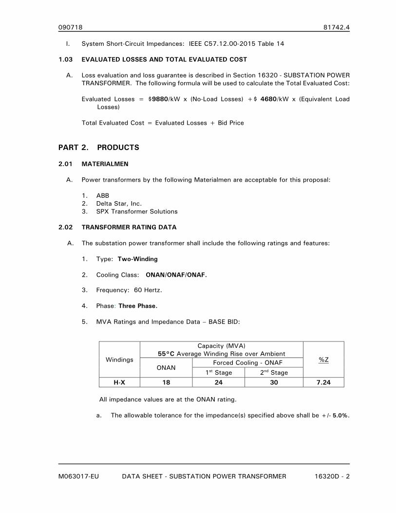
090718 81742.4
M063017-EU DATA SHEET - SUBSTATION POWER TRANSFORMER 16320D - 2
I. System Short-Circuit Impedances: IEEE C57.12.00-2015 Table 14
1.03 EVALUATED LOSSES AND TOTAL EVALUATED COST
A. Loss evaluation and loss guarantee is described in Section 16320 - SUBSTATION POWER
TRANSFORMER. The following formula will be used to calculate the Total Evaluated Cost:
Evaluated Losses = $9880/kW x (No-Load Losses) +$ 4680/kW x (Equivalent Load
Losses)
Total Evaluated Cost = Evaluated Losses + Bid Price
PART 2. PRODUCTS
2.01 MATERIALMEN
A. Power transformers by the following Materialmen are acceptable for this proposal:
1. ABB
2. Delta Star, Inc.
3. SPX Transformer Solutions
2.02 TRANSFORMER RATING DATA
A. The substation power transformer shall include the following ratings and features:
1. Type: Two-Winding
2. Cooling Class: ONAN/ONAF/ONAF.
3. Frequency: 60 Hertz.
4. Phase: Three Phase.
5. MVA Ratings and Impedance Data – BASE BID:
Windings
Capacity (MVA)
55°C Average Winding Rise over Ambient %Z
ONAN Forced Cooling - ONAF
1st Stage 2nd Stage
H-X 18 24 30 7.24
All impedance values are at the ONAN rating.
a. The allowable tolerance for the impedance(s) specified above shall be +/- 5.0%.

090718 81742.4
M063017-EU DATA SHEET - SUBSTATION POWER TRANSFORMER 16320D - 3
6. Voltage Rating (Nominal) and Insulation Levels:
Winding Voltage Connection Grounding BIL
Line Neutral
H 45000 Delta n/a 250 n/a
X 13090Y/7560 Wye Solid 110 110
7. Tap Voltages: Manual, de-energized tap changer on the HV Winding:
a. 47,400/46,200/45,000/43,800/42,600 Volts.
8. Tap Voltages: Manual, de-energized tap changer on the LV Winding:
a. None.
9. Angular Displacement: XL-N lagging HL-N by 30°.
10. Winding Material: Copper.
11. Winding Construction: Round.
12. Insulating Liquid: Mineral Oil
13. Temperature Rise: The average winding temperature rise shall not exceed 55°C at the
ONAN capacity when tested in accordance with IEEE C57.12.90. An additional
capacity of 12% shall be available when the average winding temperature rise is 65°C.
Winding temperature rise by resistance shall not exceed 65°C, hottest-spot winding
temperature rise shall not exceed 80°C.
14. Audible Sound Levels: The transformer(s) shall be designed to have average sound
pressure levels dB (A) not exceeding those listed in Table 1 of NEMA TR1–2013.
2.03 TRANSFORMER FEATURES
A. Load Tap Changer
1. A Load Tap Changer and controls shall be supplied in accordance with Section
16327 - LOAD TAP CHANGER.
B. Air Terminal Chamber (ATC):
1. An ATC is not required.
C. Bushings: At 25 kV and above, bushings shall be ABB Type ‘O Plus C’ or an engineer
approved equivalent. For 15 kV Class and below, ABB Type ‘A’ or an engineer approved
equivalent bushing shall be used. Bushings with BIL ratings below 450 kV BIL shall have a
Test Tap to measure power factor, capacitance, and partial discharge. Bushings with BIL
ratings of 450 kV BIL and above shall have a Voltage Tap. All bushings shall be ANSI #70
light gray. Bushings shall be rated as follows:

090718 81742.4
M063017-EU DATA SHEET - SUBSTATION POWER TRANSFORMER 16320D - 4
Bushing Voltage Class
(kV) BIL (kV)
Arrangement
Location Mounting
H 69 350 Segment 3 Cover
X 25 150 Segment 1 Cover
X0 25 150 Segment 1 Cover
1. Terminals/Connectors: All bushings shall have tinned NEMA 4-hole pads or as required
when Air Terminal Chamber is specified (see Section 16320).
D. Surge Arresters: All surge arresters supplied with transformer shall be Ohio Brass, Station
Class, Type SVN above 69 kV and Type EVP for 69 kV and below. Arrester color shall be
ANSI #70 Light Gray.
Winding MCOV (kV) Terminal
H 29 Galvanized NEMA 4-Hole Pads
X 8.4 Galvanized NEMA 4-Hole Pads
1. Surge arresters shall be tank mounted adjacent to the bushings or as required when an
Air Terminal Chamber is specified (see Section 16320).
E. Bushing Current Transformers: Bushing Current Transformers to be wired as described in
Section 16320 - SUBSTATION POWER TRANSFORMER. Ratio, Accuracy Class and
location shall be as follows (CT positions are designated as 1,2,3, etc, with one (1) being
closest to winding and the highest number being farthest from the winding):
Ratio Accuracy Class
H-Winding:
Position 1
(closest to winding)
600:5 C400
X-Winding:
Position 1 2000:5 C400
Xo Bushing:
Position 1 1200:5 C400
F. Revenue Meter Current Transformers
1. Are not required.
G. Tank Finish
1. Paint Color shall be ANSI #70 Light Gray.
2.04 INSTRUMENTATION AND CONTROL
A. Liquid Temperature Indicator (LTI) and Control
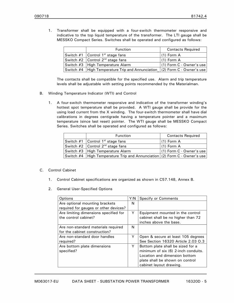
090718 81742.4
M063017-EU DATA SHEET - SUBSTATION POWER TRANSFORMER 16320D - 5
1. Transformer shall be equipped with a four-switch thermometer responsive and
indicative to the top liquid temperature of the transformer. The LTI gauge shall be
MESSKO Compact Series. Switches shall be operated and configured as follows:
Function Contacts Required
Switch #1 Control 1st stage fans (1) Form A
Switch #2 Control 2nd stage fans (1) Form A
Switch #3 High Temperature Alarm (1) Form C - Owner’s use
Switch #4 High Temperature Trip and Annunciation_ (2) Form C - Owner’s use
The contacts shall be compatible for the specified use. Alarm and trip temperature
levels shall be adjustable with setting points recommended by the Materialman.
B. Winding Temperature Indicator (WTI) and Control
1. A four-switch thermometer responsive and indicative of the transformer winding’s
hottest spot temperature shall be provided. A WTI gauge shall be provide for the
using load current from the X winding. The four-switch thermometer shall have dial
calibrations in degrees centigrade having a temperature pointer and a maximum
temperature (since last reset) pointer. The WTI gauge shall be MESSKO Compact
Series. Switches shall be operated and configured as follows:
Function Contacts Required
Switch #1 Control 1st stage fans (1) Form A
Switch #2 Control 2nd stage fans (1) Form A
Switch #3 High Temperature Alarm (1) Form C - Owner’s use
Switch #4 High Temperature Trip and Annunciation (2) Form C - Owner’s use
C. Control Cabinet
1. Control Cabinet specifications are organized as shown in C57.148, Annex B.
2. General User-Specified Options
Options Y/N Specify or Comments
Are optional mounting brackets
required for gauges or other devices?
N
Are limiting dimensions specified for
the control cabinet?
Y Equipment mounted in the control
cabinet shall be no higher than 72
inches above the base.
Are non-standard materials required
for the cabinet construction?
N
Are non-standard door handles
required?
Y Open & secure at least 105 degrees
See Section 16320 Article 2.03 O.3
Are bottom plate dimensions
specified?
Y Bottom plate shall be sized for a
minimum of six (6) 2-inch conduits.
Location and dimension bottom
plate shall be shown on control
cabinet layout drawing.
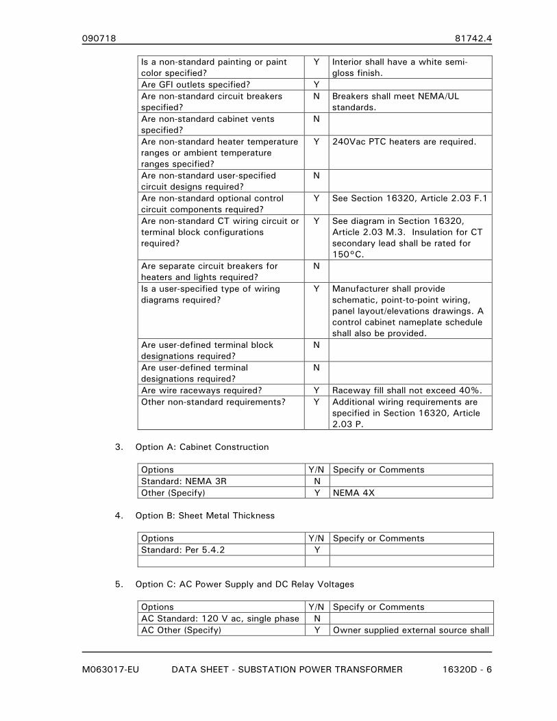
090718 81742.4
M063017-EU DATA SHEET - SUBSTATION POWER TRANSFORMER 16320D - 6
Is a non-standard painting or paint
color specified?
Y Interior shall have a white semi-
gloss finish.
Are GFI outlets specified? Y
Are non-standard circuit breakers
specified?
N Breakers shall meet NEMA/UL
standards.
Are non-standard cabinet vents
specified?
N
Are non-standard heater temperature
ranges or ambient temperature
ranges specified?
Y 240Vac PTC heaters are required.
Are non-standard user-specified
circuit designs required?
N
Are non-standard optional control
circuit components required?
Y See Section 16320, Article 2.03 F.1
Are non-standard CT wiring circuit or
terminal block configurations
required?
Y See diagram in Section 16320,
Article 2.03 M.3. Insulation for CT
secondary lead shall be rated for
150°C.
Are separate circuit breakers for
heaters and lights required?
N
Is a user-specified type of wiring
diagrams required?
Y Manufacturer shall provide
schematic, point-to-point wiring,
panel layout/elevations drawings. A
control cabinet nameplate schedule
shall also be provided.
Are user-defined terminal block
designations required?
N
Are user-defined terminal
designations required?
N
Are wire raceways required? Y Raceway fill shall not exceed 40%.
Other non-standard requirements? Y Additional wiring requirements are
specified in Section 16320, Article
2.03 P.
3. Option A: Cabinet Construction
Options Y/N Specify or Comments
Standard: NEMA 3R N
Other (Specify) Y NEMA 4X
4. Option B: Sheet Metal Thickness
Options Y/N Specify or Comments
Standard: Per 5.4.2 Y
5. Option C: AC Power Supply and DC Relay Voltages
Options Y/N Specify or Comments
AC Standard: 120 V ac, single phase N
AC Other (Specify) Y Owner supplied external source shall
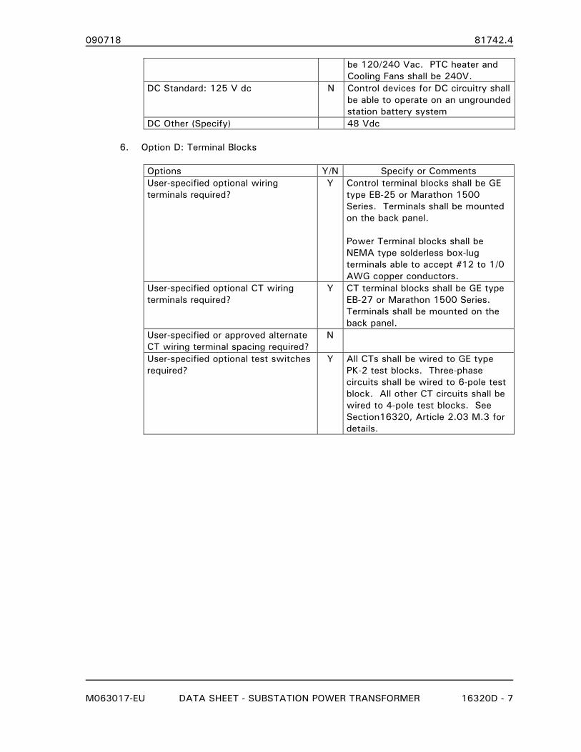
090718 81742.4
M063017-EU DATA SHEET - SUBSTATION POWER TRANSFORMER 16320D - 7
be 120/240 Vac. PTC heater and
Cooling Fans shall be 240V.
DC Standard: 125 V dc N Control devices for DC circuitry shall
be able to operate on an ungrounded
station battery system
DC Other (Specify) 48 Vdc
6. Option D: Terminal Blocks
Options Y/N Specify or Comments User-specified optional wiring
terminals required? Y Control terminal blocks shall be GE
type EB-25 or Marathon 1500
Series. Terminals shall be mounted
on the back panel.
Power Terminal blocks shall be
NEMA type solderless box-lug
terminals able to accept #12 to 1/0
AWG copper conductors.
User-specified optional CT wiring
terminals required? Y CT terminal blocks shall be GE type
EB-27 or Marathon 1500 Series.
Terminals shall be mounted on the
back panel.
User-specified or approved alternate
CT wiring terminal spacing required? N
User-specified optional test switches
required? Y All CTs shall be wired to GE type
PK-2 test blocks. Three-phase
circuits shall be wired to 6-pole test
block. All other CT circuits shall be
wired to 4-pole test blocks. See
Section16320, Article 2.03 M.3 for
details.

090718 81742.4
M063017-EU DATA SHEET - SUBSTATION POWER TRANSFORMER 16320D - 8
7. Option E: Cooling Control Switches
Y/N Specify or Comments
Do not include the standard
Auto/Off/Manual switch N
Do not include the standard manual
stage selector switch N
Supply optional lead stage selector
Switch Y Not required if a microprocessor-
based control is specified that can
provide this function.
Other N
8. Option F: Annunciator
Y/N Specify or Comments
Supply optional annunciator N
9. Option G: Automatic Transfer Switch (ATS)
Y/N Specify or Comments
Supply optional ATS N
10. Option H: Dead Front Design
Y/N Specify or Comments
Supply optional dead front design Y Swing panel(s) shall be provided
inside the control cabinet’s exterior
door(s). Cooling Control Switches,
CT circuit PK-2 blocks and LTC
controls (where applicable) shall be
mounted on the swing panel(s).
Devices mounted on the swing
panel(s) shall not prevent the outer
door(s) and swing panel(s) from
being secured in the open position.
Padlocking provisions should not be
provided on swing panel(s).
11. Option I: Visible Air Gap
Y/N Specify or Comments
Supply optional single switch on AC
power supply N
Supply optional single switch on DC
circuit
N
Supply optional multiple switches N
2.05 ADDITIONAL REQUIREMENTS
090718 81742.4
M063017-EU DATA SHEET - SUBSTATION POWER TRANSFORMER 16320D - 9
A. The following Spare Parts are to be quoted as a separate item on the Bid Form:
1. One (1) spare H, X, and Xo Bushing (if different from the X bushing)
END OF SECTION
090718 81742.4
M051515-EU LOAD TAP CHANGER 16327 - 1
SECTION 16327
LOAD TAP CHANGER
PART 1. GENERAL
1.01 SECTION INCLUDES
A. Performance and functional requirements for a Load Tap Changer.
B. Requirements for LTC control, instrumentation and communications.
1.02 RELATED SECTIONS
A. DIVISIONS O and 1 - CONTRACT DOCUMENTS AND GENERAL REQUIREMENTS: These
shall apply to all work included in this section.
B. Section 16320 - SUBSTATION POWER TRANSFORMER.
1.03 REFERENCES
A. Published Specifications, standards, tests, or recommended methods of trade, industry, or
governmental organizations apply to work in this section where cited in Section 01090 -
REFERENCE STANDARDS and in the listing below.
1. IEEE C57.12.00 - Standard for General Requirements for Liquid-Immersed
Distribution, Power, and Regulating Transformers
2. IEEE C57.12.10 - Standard Requirements for Liquid-Immersed Power Transformers
3. IEEE C57.131 - Standard Requirements for Tap Changers
1.04 SUBMITTALS
A. Shop drawings shall be submitted for approval in accordance with Section 01301 -
SUBMITTALS and Section 01341 - SHOP DRAWINGS.
B. Submittals shall consist of, but not limited to, the following:
1. Outline and Details
2. LTC Nameplate Drawing
3. Schematics and Wiring Diagrams
4. LTC Operating Instructions
5. Tap Changer Control/Instrumentation Data and Instruction Manuals
C. Final Drawings and Manuals shall be provided prior to shipment in accordance with Section
01721 - PROJECT RECORD DOCUMENTS.

090718 81742.4
M051515-EU LOAD TAP CHANGER 16327 - 2
1.05 WARRANTY
A. Warranty shall be the same as the substation power transformer supplied or Materialman’s
standard which ever affords greater protection to the Owner.
PART 2. PRODUCTS
2.01 MANUFACTURERS
A. ABB Electric Type UZE, UZF
B. Waukesha Type UZD
C. Reinhausen Type RMV-II
2.02 COMPONENTS
A. Load Tap Changer (LTC)
1. The LTC shall be designed, manufactured and tested to IEEE Standard C57.131 and
IEEE Standard C57.12.10.
2. The active part of the LTC shall be in a separate compartment. There shall be no
mixing of oil between compartments, and each compartment shall have sample and
draining provisions independent of the other compartment.
3. The preferred physical location of the LTC is on the tank wall of Segment 2.
4. LTC shall be the high-speed resistive or vacuum interrupter-reactance type.
5. The LTC shall not limit the transformer from being loaded in accordance with IEEE
Standard C57.91. LTC taps shall have full rated kVA capacity on taps above normal
and a current rating corresponding to full load current at rated voltage on taps below
normal voltage.
6. Drive mechanism motor shall be rated 230 Vac and be connected to an Owner
supplied 120/240 Vac source.
7. Resistive-type LTCs shall complete a tap change once started, either electrically or
manually. LTC shall not be capable of remaining in a mid-tap position due to loss of
operating voltage during electrical operation or during manual operation.
Manufacturers proposing a reactance-type LTC shall address the impact of losing
control power when the mechanism is in a mid-tap position as part of their proposal.
If the LTC provided is capable of this condition, an alarm shall be provided for
indication.
B. LTC Features
1. The position indicator shall have drag hands to indicate both the maximum raise and
lower position. The reset means for the drag hands may be either electrical or
mechanical. If mechanical reset is used, the reset lever shall be no higher than 72
inches above the base of the transformer.
2. The LTC’s oil compartment shall be equipped with a mechanical pressure relief device
and a magnetic liquid level gauge. Alarm contacts shall be provided for both devices
090718 81742.4
M051515-EU LOAD TAP CHANGER 16327 - 3
as specified in Section 16320.
3. A dehydrating breather shall be provided for the LTC’s oil compartment.
4. An Oil Filtration System shall be provided for arcing-in-oil designs. The Filtration
System shall be manufactured by Waukesha Electric Systems or as approved by
Engineer.
5. LTCs that use arcing-under-oil designs shall have a sudden pressure relay and
associated equipment for the LTC’s oil compartment to initiate de-energizing of the
power transformer. The sudden pressure relay provided shall be as specified in
Section 16320.
6. An operations counter shall be provided to indicate the number of tap changer
operations.
7. A neutral position cam operated switch shall be included and wired to the
transformer’s control cabinet for use with a neutral position light indicator.
C. Windings
1. The tap winding shall be fully distributed and wound on a separate winding tube from
the high and low voltage windings. Winding conductors shall be copper. Where
partially distributed windings are proposed, the tap sections must be arranged
symmetrically about the magnetic and electric center of the main windings. The
Materialman must discuss the details of the partially distributed design as part of the
Proposal to receive full consideration.
2. A series transformer, when required, shall be constructed to Class 2 power
transformer standards including circular core and coil design using disc or helical type
winding construction with all copper conductors.
3. When a reactance-type LTC is provided, the preventative autotransformer (PA) shall be
constructed to Class 2 power transformer standards including circular core and coil
design using disc or helical type winding construction with all copper conductors.
An alternate PA design incorporating a rectangular coil with full height copper strip
conductor is acceptable. Windings shall be designed as a 2:1 autotransformer with
two windings of equal turns and current carrying capacity. Windings shall be wound
in a radially interleaved arrangement. Resulting design shall exhibit essentially zero
axial and radial forces during short circuits.
D. Nameplate
1. A separate nameplate shall be attached to the LTC mechanism providing LTC data
required in C57.131 and also including but not limited to:
a. Model Number, Type, Serial Number
b. Quantity of oil in compartment(s)
c. Instruction Manual Number
d. Vacuum capability of barrier between LTC and transformer main tank

090718 81742.4
M051515-EU LOAD TAP CHANGER 16327 - 4
E. Drive Mechanism Enclosure
1. The Drive Mechanism enclosure shall meet the specifications for the Control Cabinet
and Wiring detailed in Sections 16320 and 16320D.
F. Controls and Instrumentation
1. All controls required to allow independent or parallel operation with an identical unit
purchased under this contract shall be provided. Parallel operation shall utilize the
circulating current method.
2. The LTC controls required shall include:
a. Beckwith model M-2001D Digital Tapchanger Control, Style M-2001D-6-V-4S-20-
F-0-S-0-0, combined with an M-2270B Adapter Panel. The M-2270B shall
include the option control switches for SCADA Cutout, Voltage Reduction and
SCAMP.
b. Auxiliary CTs as required for the M-2001 control’s line drop compensation
function shall be provided.
c. Beckwith M-0329B back-up control shall be provided.
d. Beckwith parallel balancing module M-0115A shall be provided to allow for
parallel operation with an identical LTC transformer. Isolated dry contacts wired
to terminal blocks shall be provided to indicate switch position (parallel or
independent) for SCADA indication.
e. Beckwith AC current relay, Module M-0127A, shall be included in the circulating
current circuit of paralleled LTC transformers to guard against excessive
circulating current.
3. To accommodate access to the LTC control’s settings and data logging, one copy of
the Beckwith M-2029 "Tap Talk" communications software shall be provided.
4. Tap Position Tracking
a. Materialman shall provide an INCON Model 1250-LTC with a 0-1 mA analog
output to signal the LTC’s tap position to the M-2001 control. Materialman shall
also provide a Beckwith M-2025B (Current Loop Interface Module) and other
accessories necessary to track the LTC’s tap position with the M-2001 control.
b. Wired analog connections shall use #16 AWG shielded twisted pair wire.
c. Materialman is responsible for programming, setup and calibration of the INCON
device.
5. The LTC controls shall be mounted in the transformer main control cabinet on a
hinged, swing-out inner panel for easy access behind the panel. All controls,
operations counter, position indicator reset or other devices requiring operation by
utility personnel shall be no higher than 72 inches above base of transformer. In
addition to the controls listed, the following features shall also be included:
Project Date A/H EU MASTER
M051515-EU LOAD TAP CHANGER 16327 - 5
6. All interconnection wiring between the control modules, current transformers, auxiliary
equipment, and field terminal blocks shall be provided to achieve a completely
functional automatic voltage regulating control system. Wiring shall meet the
specifications listed in Section 16320. Terminations shall include all interconnections
between the available input/output functions of the M-2001 including but not limited
to the following:
a. External sensing voltage input.
b. LTC paralleling connections.
c. Self-Test alarm contact outputs.
d. User programmable alarm contact input.
e. Tap change inhibit contact input.
f. Multi-step voltage reduction.
g. LTC tap position transducer output.
h. Sensing voltage input.
G. Auxiliary and Control Power
1. Owner-supplied external source(s) are shown in the DATA SHEET. Materialman
selected devices shall be rated to operate at the specified voltages.
2. Sensing voltage for the LTC controls shall be 120 VAC, 10/ , 60 Hz, and will be
supplied by the OWNER.
2.03 FABRICATION
A. Bolted access covers on the LTC compartment shall be hinged and removable.
B. There shall be a spill lip at the bottom edge of the load tap changer cabinet to prevent oil
spillage when the cabinet is opened for maintenance.
C. LTC design shall be capable of withstanding full vacuum in the main transformer tank
without damage to LTC compartment or components. If the barrier between the main tank
and the LTC compartment requires an equalizing vacuum, warning signs should be placed
near the appropriate main tank fittings and in the instruction manual.
D. When operating the hand crank with the transformer under load is not appropriate, a
warning sign should be placed near the hand crank coupling.
PART 3. EXECUTION
(NOT USED)
END OF SECTION
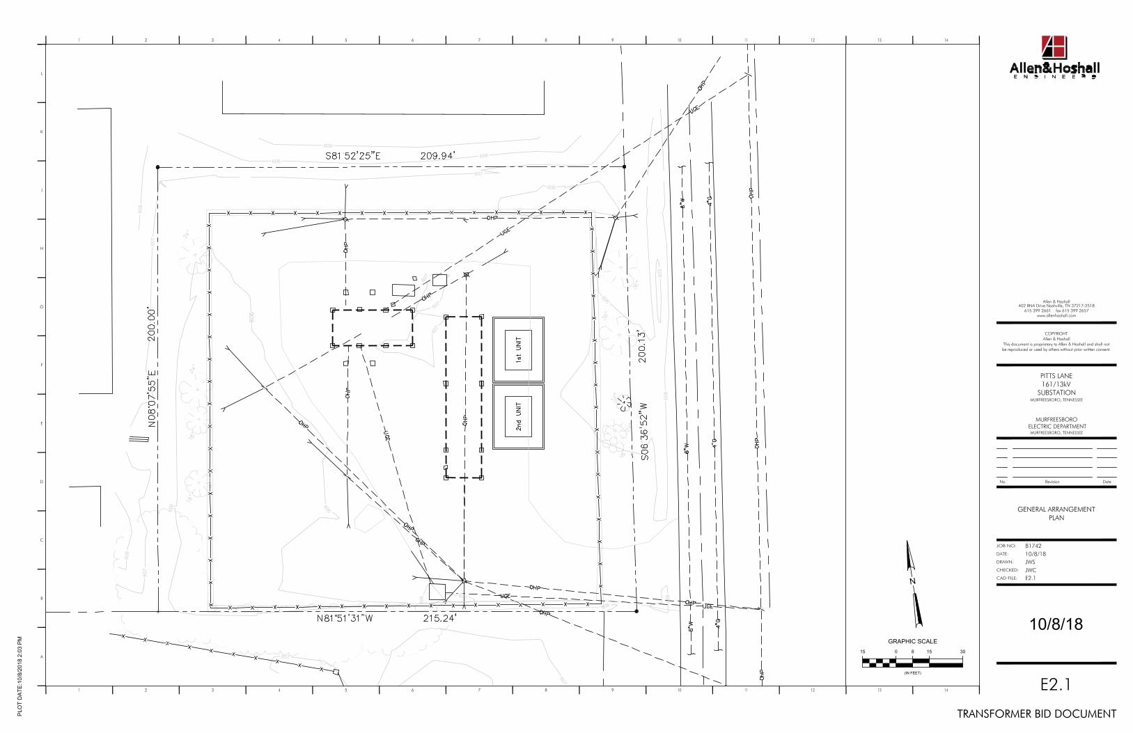
605
606
606
606
607
607
607
607
608
609
606606 606
607
606
607
606
608
607
608608
607
606
15 0 8 15 30
GRAPHIC SCALE
(IN FEET)
N
1 2
A
B
3 4 5 6 7 8 9 10 11 12 13 14
D
E
F
G
H
J
K
L
1 2 3 4 5 6 7 8 9 10 11 12 13 14
No. Revision Date
DATE:
JOB NO:
DRAWN:
CAD FILE:
CHECKED:
C
COPYRIGHTAllen & Hoshall
This document is proprietary to Allen & Hoshall and shall notbe reproduced or used by others without prior written consent.
8174210/8/18
402 BNA Drive Nashville, TN 37217-2518615 399 2661 fax 615 399 2657
Allen & Hoshall
www.allenhoshall.com
PL
OT
DA
TE
:10
/8/2
01
8 2
:03
PM
PITTS LANE161/13kV
SUBSTATIONMURFREESBORO, TENNESSEE
MURFREESBORO ELECTRIC DEPARTMENT
MURFREESBORO, TENNESSEE
TRANSFORMER BID DOCUMENT
E2.1
GENERAL ARRANGEMENTPLAN
JWSJWCE2.1
10/8/18