specification – masonry · masonry units, pavers, flags and segmental retaining wall units -...
TRANSCRIPT
SPECIFICATION – MASONRY Scope This section covers the construction of masonry in buildings, including unreinforced brickwork and blockwork wall, piers and lintels. It also includes the construction of reinforced hollow blockwork.
Note Additional requirements for the construction of reinforced hollow concrete blockwork for stems of gravity retaining walls is set out in Concrete Masonry Association of Australia Manual MA51.
Building Regulations and Standards All materials and construction shall comply with the most recent version of:
• the relevant parts of the Building Regulations; • the Standards referred to therein; • other Standards nominated in this specification; and • other relevant Regulations.
Relevant Standards AS 3700 Masonry structures AS 4773.1 Residential masonry Part 1: Design AS 4773.2 Residential masonry Part 1: Construction AS/NZS 4455 Masonry units, pavers, flags and segmental retaining wall units - Masonry units AS/NZS 4456 Masonry units and segmental pavers and flags– Methods of test AS/NZS 2904 Damp-proof courses and flashings AS/NZS 2699.1 Built-in components for masonry construction - Wall ties AS/NZS 2699.2 Built-in components for masonry construction - Connectors and accessories AS/NZS 2699.3 Built-in components for masonry construction - Lintels and shelf angles (durability requirements) AS 3972 Portland and blended cements AS 1316 Masonry composite cement AS 1672.1 Limes and Limestone - Limes for building AS 2758.1 Aggregates and rock for engineering purposes - Concrete aggregates AS 3660.1 Termite management – New Building work AS 3660.2 Termite management – In and around existing buildings and structures - Guidelines AS/NZS 4680 Hot-dip galvanised (zinc) coatings on fabricated ferrous articles AS/NZS 4534 Zinc and zinc/aluminium-alloy coatings on steel wire AS 2837 Wrought alloy steels – stainless steel bars and semi-finished products AS/NZS 4792 Hot-dip galvanised (zinc) coatings on ferrous hollow sections, applied a continuous
or specialised process AS/NZS 4791 Hot-dip galvanised (zinc) coatings on ferrous open sections, applied by an in-line process AS/NZS 4671 Steel reinforcing materials AS 1397 Steel sheet and strip AS 3600 Concrete structures AS 2870 Residential slabs and footings – Construction
Mortar For general applications (except as listed for M4), Type M3 mortar shall be used, and shall consist by volume of:
1 part GP or GB cement, 1 part lime, 6 parts sand (water thickener optional) 1 part GP or GB cement, 5 parts sand plus water thickener 1 part masonry cement, 4 parts sand.
For the applications listed below, Type M4 mortar shall be used, and shall consist by volume of:
1 part GP or GB cement, 0.5 part lime, 4.5 parts sand (water thickener optional) 1 part GP or GB cement, 4 parts sand plus water thickener 1 part GP or GB cement, 0-0.25 parts lime, 3 parts sand (water thickener optional) 1 part masonry cement, 3 parts sand.
This applies to: • Elements in interior environments subject to saline wetting and drying • Elements below a damp-proof course or in contact with ground in aggressive soils • Elements in severe marine environments • Elements in saline or contaminated water including tidal splash zones • Elements within 1 km of an industry producing chemical pollutants.
Damp-Proof Course Damp-proof-courses shall be built into the masonry in accordance with the Drawings, Building Regulations and relevant Standard (AS 3700, AS 4773.1, AS 4773.2). Unless stated otherwise, damp-proof-courses shall be: • Placed under walls to provide a continuous damp-proof barrier around the building • Lapped not less than 150 mm at joints • Projecting through the entire width of the masonry and project beyond the external face of the
masonry • Stepped at changes of floor level • Positioned (if applicable) under the coping of any parapet more than 300 mm above adjoining
roof cladding • Positioned (if applicable) in chimney stacks, 150 mm to 300 mm above the highest junction of
roof and chimney • At least 75 mm above finished surface level of adjacent paved, concreted or landscaped
areas that slope away from the wall • At least 50 mm above finished paved or concreted areas sloping at least 50 mm over the first
1 m from the building and protected from the direct effects of the weather by a carport, verandah or similar
• At least 150 mm above the adjacent finished ground in all other cases.

Flashings Flashings shall be built into the masonry in accordance with the Drawings, Building Regulations and relevant Standard (AS 3700, AS 4773.1, AS 4773.2). Unless stated otherwise, flashings shall be: • Fixed with clouts to timber studs or built into an inner leaf of masonry as applicable • Built into the external leaf of walls exposed to weather, extending across the cavity, • Turned up 150 mm and nailed to the frame or built 30 mm into an inner leaf of masonry, • Positioned at openings (unless they are protected by an overhang), where they shall extend
100 mm past the end of opening and be turned up to prevent leakage.
Termite Protection Termite protection measures shall comply with the Building Regulations and the relevant Standard (AS 3660.1) The aim of most termite barriers is to force the termites to the surface of the structure, where they are visible and can be easily eradicated. Some termite barriers also include chemicals that deter the termites from passing. Other systems, involving chemical dosing and graded stone barriers may be applicable, but must be properly maintained. Refer to the relevant materials specifications. Termite protection shall provide a continuous barrier that prevents termites from entering the building undetected. The critical areas for termite entry, including the external perimeter, construction joints and plumbing penetrations, shall be protected and treated by a termite management system. The system installation shall conform to the manufacturer’s guidelines. A manufacturer’s warranty for a minimum of fifty (50) years shall be provided. The warranty shall be renewable on an annual basis, base on annual inspection by the system installation organisation. Such a warranty shall provide for timber replacement should a system breach occur. A certificate permanently fixed to the building in a prominent location, such as a meter box, kitchen cupboard, or similar, shall indicate the following: • Method of protection. • Date of installation. • Life expectancy of any termiticide and the required re-injection date. • Installer’s or manufacturer’s recommendations for the scope and frequency of future
inspections for termite activity, not greater than 12 months.
Sheet material acting as a termite barrier within the masonry and their joints shall be constructed of termite-resistant materials, such that termites are unable to pass through them. The maximum aperture size of a perforated sheet material barrier shall be sufficiently small as to deny access to foraging termite species of the region. Combinations of materials likely to cause electrolytic reaction shall not be used, e.g. stainless steel mesh shall not be used in contact with mild steel reinforcement. Slip Joints Slip joint material shall be placed between unreinforced masonry walls and any supported concrete slab.
Wall Ties Wall ties shall be installed in accordance with the Drawings, Building Regulations and relevant Standard (AS 3700, AS 4773.1, AS 4773.2). Joint Reinforcement One layer of joint reinforcement shall be incorporated into concrete or calcium silicate masonry at points of potential cracking such as at the corners of door or window openings. Lintels and Arch Bars Lintels and arch bars shall be built in over openings in excess of 1.0 metre accordance with the Drawings, Building Regulations and relevant Standard (AS 3700, AS 4773.1, AS 4773.2). Anchorages Anchorages, including those to tie down roof structures, shall be installed at specified locations, and in accordance with the Drawings, Building Regulations and relevant Standard (AS 3700, AS 4773.1, AS 4773.2). Mortar Joints Mortar joints shall comply with the Drawings, Building Regulations and relevant Standard (AS 3700, AS 4773.1, AS 4773.2). Unless stated otherwise, mortar joints shall comply with the following: • Mortar joint shall be 10 mm thick. • Mortar joints in solid or cored face masonry shall be fully bedded. Joints shall be as specified
on the drawings. • Mortar joints in solid or cored backup or non-face masonry shall be fully bedded and flush
jointed. • Mortar joints in hollow blockwork, shall be face shell bedded and shall be ironed, unless a
flush joint is specified for aesthetic reasons. Weepholes Weepholes shall comply with the Drawings, Building Regulations and relevant Standard (AS 3700, AS 4773.1, AS 4773.2). Unless stated otherwise, weep holes shall be built into the external leaf of cavity walls or veneer walls at centres not exceeding 1.2 metres in the course immediately above a DPC or flashing, except where the head or sill opening is less than 1.0 metre wide.
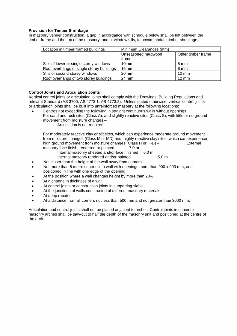
Provision for Timber Shrinkage In masonry veneer construction, a gap in accordance with schedule below shall be left between the timber frame and the top of the masonry, and at window sills, to accommodate timber shrinkage.
Location in timber framed buildings Minimum Clearances (mm) Unseasoned hardwood
frame Other timber frame
Sills of lower or single storey windows 10 mm 5 mm Roof overhangs of single storey buildings 16 mm 8 mm Sills of second storey windows 20 mm 10 mm Roof overhangs of two storey buildings 24 mm 12 mm
Control Joints and Articulation Joints Vertical control joints or articulation joints shall comply with the Drawings, Building Regulations and relevant Standard (AS 3700, AS 4773.1, AS 4773.2). Unless stated otherwise, vertical control joints or articulation joints shall be built into unreinforced masonry at the following locations: • Centres not exceeding the following in straight continuous walls without openings
For sand and rock sites (Class A), and slightly reactive sites (Class S), with little or no ground movement from moisture changes – Articulation is not required For moderately reactive clay or silt sites, which can experience moderate ground movement from moisture changes (Class M or MD) and highly reactive clay sites, which can experience high ground movement from moisture changes (Class H or H-D) – External masonry face finish, rendered or painted 7.0 m
Internal masonry sheeted and/or face finished 6.0 m Internal masonry rendered and/or painted 5.0 m
• Not closer than the height of the wall away from corners • Not more than 5 metre centres in a wall with openings more than 900 x 900 mm, and
positioned in line with one edge of the opening • At the position where a wall changes height by more than 20% • At a change in thickness of a wall • At control joints or construction joints in supporting slabs • At the junctions of walls constructed of different masonry materials • At deep rebates • At a distance from all corners not less than 500 mm and not greater than 3000 mm.
Articulation and control joints shall not be placed adjacent to arches. Control joints in concrete masonry arches shall be saw-cut to half the depth of the masonry unit and positioned at the centre of the arch.
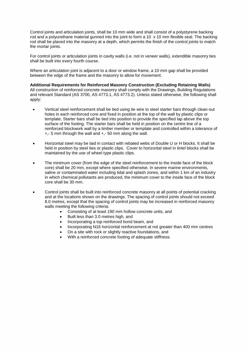
Control joints and articulation joints, shall be 10 mm wide and shall consist of a polystyrene backing rod and a polyurethane material gunned into the joint to form a 10 x 10 mm flexible seal. The backing rod shall be placed into the masonry at a depth, which permits the finish of the control joints to match the mortar joints. For control joints or articulation joints in cavity walls (i.e. not in veneer walls), extendible masonry ties shall be built into every fourth course. Where an articulation joint is adjacent to a door or window frame, a 10 mm gap shall be provided between the edge of the frame and the masonry to allow for movement. Additional Requirements for Reinforced Masonry Construction (Excluding Retaining Walls) All construction of reinforced concrete masonry shall comply with the Drawings, Building Regulations and relevant Standard (AS 3700, AS 4773.1, AS 4773.2). Unless stated otherwise, the following shall apply: • Vertical steel reinforcement shall be tied using tie wire to steel starter bars through clean-out
holes in each reinforced core and fixed in position at the top of the wall by plastic clips or template. Starter bars shall be tied into position to provide the specified lap above the top surface of the footing. The starter bars shall be held in position on the centre line of a reinforced blockwork wall by a timber member or template and controlled within a tolerance of +,- 5 mm through the wall and +,- 50 mm along the wall.
• Horizontal steel may be laid in contact with rebated webs of Double U or H blocks. It shall be
held in position by steel ties or plastic clips. Cover to horizontal steel in lintel blocks shall be maintained by the use of wheel type plastic clips.
• The minimum cover (from the edge of the steel reinforcement to the inside face of the block
core) shall be 20 mm, except where specified otherwise. In severe marine environments, saline or contaminated water including tidal and splash zones, and within 1 km of an industry in which chemical pollutants are produced, the minimum cover to the inside face of the block core shall be 30 mm.
• Control joints shall be built into reinforced concrete masonry at all points of potential cracking
and at the locations shown on the drawings. The spacing of control joints should not exceed 8.0 metres, except that the spacing of control joints may be increased in reinforced masonry walls meeting the following criteria:
• Consisting of at least 190 mm hollow concrete units, and • Built less than 3.0 metres high, and • Incorporating a top reinforced bond beam, and • Incorporating N16 horizontal reinforcement at not greater than 400 mm centres • On a site with rock or slightly reactive foundations, and • With a reinforced concrete footing of adequate stiffness.

Masonry Units Masonry units shall be fired clay, concrete or calcium silicate units complying with the Drawings, Building Regulations and relevant Standard (AS/NZS 4455.1). Unless stated otherwise, properties shall be not less than: • Masonry units shall comply with Dimensional Category DW1, except that split or irregular faces
may be DW0. Concrete units usually comply with Dimensional Category DW4 , which is more stringent than for DW1.
• Masonry units shall meet General Purpose Salt Attack Resistance Grade, except for applications requiring Exposure Grade. Applications requiring Exposure Grade are:
saline wetting or drying, aggressive soils, severe marine environments, saline or contaminated water including tidal or splash zones, or within 1 km of a industry producing chemical pollutants
• Masonry units shall have a Characteristic Compressive Strength not less than a value specified by the Engineer. In the absence of such specification, masonry units shall have Characteristic Compressive Strengths not less than the following values.
Minimum Characteristic Compressive Strength of Masonry Units 1 Application Hollow units2
Solid, cored or horizontally cored units3
Reinforced masonry 15.0 MPa Loadbearing masonry 15.0 MPa 10.0 MPa Non-loadbearing masonry 10.0 MPa 3.0 MPa Notes 1. Values of minimum characteristic compressive strength specified by the Engineer over-ride the values given in this table. Designers and specifiers should check with the manufacturers the availability of particular strength grades. 2. For hollow units, compressive strength is measured using face shell bedding. 3. For solid, cored or horizontally cored units, compressive strength is measured using full bedding.
• Masonry units intended for face applications and exposed to the weather shall have: Permeability not more than 2 mm/minute Efflorescence Potential of Nil or Slight Colour and texture within an agreed range.
• Masonry units intended for exposure to lateral loads in excess of 0.5 kPa shall have a Characteristic Lateral Modulus of Rupture not less than 0.8 MPa.
• Concrete masonry units shall have a Mean Coefficient of Residual Drying Contraction not
more than 0.6 mm/m.

• Masonry units for reinforced masonry applications shall have the following properties:
If units are intended to incorporate both horizontal and vertical reinforcement and are not protected both sides by a waterproof membrane, they shall be “H” or “Double U” configuration;
Units may be fully grouted and may be reinforced both vertically and horizontally; Grout may flow easily around and enclose the reinforcement in all cores; and Cover is consistent with the requirements for durability, strength and fire resistance
as appropriate Definitions • Dimensional Category DW0 - No Requirements • Dimensional Category DW1 - Average deviation of a sample of 20 units; +,- 2.5 mm
(dimensions under 150 mm); +,- 4.5 mm (dimensions 150 to 250 mm); +,- 5.0 mm (dimensions over 250 mm)
• Dimensional Category DW4 - For a sample of 20 units, the standard deviation of work sizes shall be not more than 2 mm, and the difference between the mean and the work size shall be not more than 3 mm. For split faces, the dimensional deviations shall not apply to the width of the unit, provided the average width is not less than 90% of the work size.
• General Purpose Salt Attack Resistance Grade - Performance such that it is possible to demonstrate that the product has a history of surviving under non-saline environmental conditions similar to those existing at the site considered, but not expected to meet the mass loss criterion for Exposure Grade Salt Attack Resistance Grade.
• Exposure Grade Salt Attack Resistance Grade - Performance such that it is possible to demonstrate that the product has a history of surviving under saline environmental conditions similar to those existing at the site considered; and less than 0.2 grams mass loss in 40 cycles in AS/NZS 4456.10, Method B test.
Cement Cement shall be Type GP portland cement or GB blended cement complying with the relevant Standard.(AS 3972). Masonry Cement Masonry cement shall comply with the relevant Standard (AS 1316). Lime Lime shall be hydrated building lime complying with complying with the relevant Standard (AS 1672). Water Thickener Water thickener shall be methyl-cellulose based.

Sand Sand shall be well graded and free from salts, vegetable matter and impurities. Sand shall not contain more than 10% of the material passing the 75 micron sieve. Sand within the following grading limits complies with this requirement and is deemed suitable for concrete masonry. Sieve Percent Passing 4.76 mm 100 2.36 mm 95–100 1.18 mm 60–100 600 µn 30–100 300 µm 10–50 150 µm 0–10 75 µm 0–4 Concrete Grout Concrete grout shall comply with the Drawings, Building Regulations and relevant Standard (AS 3700, AS 4773.1, AS 4773.2). Unless stated otherwise, properties shall be:
• a minimum portland cement content of 300 kg/cubic metre; • a maximum aggregate size of 10 mm; • sufficient slump to completely fill the cores; and • minimum compressive cylinder strength of 20 MPa
Joint Material Joint material shall comply with the Drawings, Building Regulations and relevant Standard (AS 3700, AS 4773.1, AS 4773.2). Unless stated otherwise:
• Backing rod for control joints, expansion joints and articulation joints shall be expanded polystyrene tube or bead or, rigid steel backing profile with closed cell foam adhered to the metal profile face.
• Joint sealant shall be gun grade multi-purpose polyurethane sealant. • Control joints and articulation joints shall incorporate de-bonding tape.
Intumescent seals shall be acrylic co-polymer sealant capable of providing the requisite fire performance as specified in the Drawings and/or Building Regulations as appropriate. Damp Proof Course Damp-proof courses (DPCs) shall comply with the Drawings, Building Regulations and relevant Standard (AS 3700, AS/NZS 2904). Unless stated otherwise damp-proof courses (DPCs) shall consist of one of the following options.
• A material complying with the Standard AS/NZS 2904; • Embossed black polyethylene film of high impact resistance and low slip, with a nominal
thickness of 0.5 mm prior to embossing, and meeting the requirements of the relevant Standard (Clause 7.6 of AS/NZS 2904);
• Polyethylene coated metal damp proof courses with an aluminium core not less than 0.1 mm thick, shall be coated both sides with bitumen adhesive enclosed in polyethylene film not less than 0.1 mm thick on each face, and has a nominal total thickness of not less than 0.5 mm prior to embossing;

• Bitumen impregnated materials of not less than 2.5 mm thickness, that meet the requirements of the relevant Standard (Clause 7.5 of AS/NZS 2904), when used in walls that are not higher than 7.8 m above the level of the DPC;
• Termite shields (with no penetrations) continuous throughout the wall or pier.
Notes: Metal and metal-cored damp-proof courses and termite shields shall not be used in locations with saline ground water or subject to rising salt damp.
Flashings Flashings shall comply with the Drawings, Building Regulations and relevant Standard (AS 3700, AS/NZS 2904).
• Metal and metal-cored flashings shall not be used in locations that expose them to saline ground water or rising salt damp.
• Metal flashings shall be compatible with the materials with which they are in contact, and shall not give rise to electrolytic action. If there is potential for electrolytic action to occur, flashings shall be isolated by inert materials.
• Flashings intended to hold their shape shall be manufactured from rigid material. (e.g. metal cored material)
Unless stated otherwise flashings shall consist of one of the following options: Flashing in Concealed Locations (e.g. cavity flashings) shall be one of the following:
• Uncoated annealed lead having a mass not less than 10 kg/m2 in lengths not exceeding 1.5 m, but shall not be used on any roof that is used to catch potable water;
• Uncoated copper having a mass not less than 2.8 kg/m2 and having a thickness of 0.3 to 0.5 mm;
• Bitumen coated metal (normally aluminium) with a total coated thickness of 0.6 mm to 1.0 mm;
• Zinc coated steel with a thickness not less than 0.6 mm; • Embossed/quilted polyethylene sheet with an average thickness not less than 0.5 mm
Flashings in Exposed Locations (e.g. flashings from the roof to masonry wall) shall be one of the following:
• Uncoated annealed lead having a mass not less than 20 kg/m2 in lengths not exceeding 1.5 m, but shall not be used on any roof that is used to catch potable water;
• Uncoated copper having a mass not less than 2.8 kg/m2 and having a thickness of 0.3 to 0.5 mm;
• Bitumen coated metal (normally aluminium) with a total coated thickness of 0.6 mm to 1.0 mm;
• Zinc coated steel of thickness not less than 0.6 mm.

Termite Barriers Consisting of Woven Stainless Steel Mesh Woven stainless steel mesh acting as a termite barrier shall comply with the Drawings, Building Regulations and relevant Standard (AS 3660.1). Unless stated otherwise, properties shall be not less than the following:
• Mesh shall be woven wire from a fine wire loom. • Wire shall be stainless steel grade 304 or 316 (AS 1449). • Wire diameter shall be not less than 0.18 mm. • Aperture size shall be not greater than 0.66 mm × 0.45 mm, except in those locations where a
very small species of heterotermes vagus is present (e.g. parts of northern Australia), the aperture shall be reduced to a maximum of 0.40 × 0.40 mm
• Pipe collars, manufactured from woven stainless steel mesh with a 50 mm annulus, shall be attached to any penetrating service by a stainless steel clamp. Such collars shall be:
Embedded in the concrete; or Clamped and parged to the top surface of the slab, and protected from damage by covering with a tile mortar bed or a false floors of cupboards or vanities. The clamp shall be sealed with the parging mix.
Termite Barrier Parging Material for Woven Stainless Steel Mesh Parging material, for woven stainless steel mesh acting as a termite barrier, shall comply with the Drawings, Building Regulations and relevant Standard (AS 3660.1). Unless stated otherwise, parging material shall be a highly modified cementitious grout of a water-dispersed copolymer with a dry mixture of Type GP portland cement and sieved aggregate of a size that passes readily through the woven stainless steel mesh. Hardened parging material shall provide:
• Termite resistance, when in contact with soil and termite workings; • Bond strength (mesh to substrate) of not less than 1 kN/m at 28 days for a temperature range
of 10°C to 30°C at a relative humidity range of 10%RH to 70%RH; and for at least 60 freeze-thaw cycles in saline solution between −15°C and 18°C.
Termite Barriers Consisting of Composite Fibre Blanket and Plastic Membrane with Termiticide Impregnation Termite barriers, consisting of composite fibre blanket and plastic membrane with termiticide impregnation, shall comply with the Drawings, Building Regulations and relevant Standard (AS 3660.1). Unless stated otherwise, properties shall be not less than:
• Internal non-woven fibre blanket, not less than 200 grams per square metre, • Impregnated with termiticide of pyrethroid deltametherin crystals to a loading of not less than
1 gram per square metre (low toxicity to warm blooded animals which both strongly repels and kills termites),
• Bonded to a top moisture vapour barrier of low density polyethylene (LDPE), not less than 200 microns thick,
• Bonded to a bottom membrane of low density polyethylene (LDPE) not less than 50 microns thick, to prevent the termiticide leaching into soil.
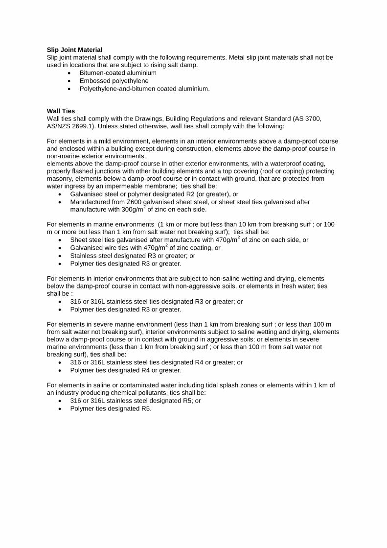
Slip Joint Material Slip joint material shall comply with the following requirements. Metal slip joint materials shall not be used in locations that are subject to rising salt damp.
• Bitumen-coated aluminium • Embossed polyethylene • Polyethylene-and-bitumen coated aluminium.
Wall Ties Wall ties shall comply with the Drawings, Building Regulations and relevant Standard (AS 3700, AS/NZS 2699.1). Unless stated otherwise, wall ties shall comply with the following: For elements in a mild environment, elements in an interior environments above a damp-proof course and enclosed within a building except during construction, elements above the damp-proof course in non-marine exterior environments, elements above the damp-proof course in other exterior environments, with a waterproof coating, properly flashed junctions with other building elements and a top covering (roof or coping) protecting masonry, elements below a damp-proof course or in contact with ground, that are protected from water ingress by an impermeable membrane; ties shall be:
• Galvanised steel or polymer designated R2 (or greater), or • Manufactured from Z600 galvanised sheet steel, or sheet steel ties galvanised after
manufacture with 300g/m2 of zinc on each side.
For elements in marine environments (1 km or more but less than 10 km from breaking surf ; or 100 m or more but less than 1 km from salt water not breaking surf); ties shall be:
• Sheet steel ties galvanised after manufacture with 470g/m2 of zinc on each side, or • Galvanised wire ties with 470g/m2 of zinc coating, or • Stainless steel designated R3 or greater; or • Polymer ties designated R3 or greater.
For elements in interior environments that are subject to non-saline wetting and drying, elements below the damp-proof course in contact with non-aggressive soils, or elements in fresh water; ties shall be :
• 316 or 316L stainless steel ties designated R3 or greater; or • Polymer ties designated R3 or greater.
For elements in severe marine environment (less than 1 km from breaking surf ; or less than 100 m from salt water not breaking surf), interior environments subject to saline wetting and drying, elements below a damp-proof course or in contact with ground in aggressive soils; or elements in severe marine environments (less than 1 km from breaking surf ; or less than 100 m from salt water not breaking surf), ties shall be:
• 316 or 316L stainless steel ties designated R4 or greater; or • Polymer ties designated R4 or greater.
For elements in saline or contaminated water including tidal splash zones or elements within 1 km of an industry producing chemical pollutants, ties shall be:
• 316 or 316L stainless steel designated R5; or • Polymer ties designated R5.
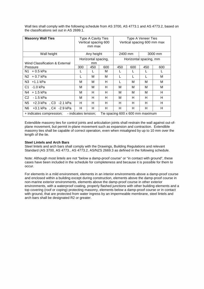
Wall ties shall comply with the following schedule from AS 3700, AS 4773.1 and AS 4773.2, based on the classifications set out in AS 2699.1. Masonry Wall Ties Type A Cavity Ties
Vertical spacing 600 mm max
Type A Veneer Ties Vertical spacing 600 mm max
Wall height Any height 2400 mm 3000 mm
Wind Classification & External Pressure
Horizontal spacing, mm
Horizontal spacing, mm
300 450 600 450 600 450 600 N1 + 0.5 kPa L L M L L L L N2 + 0.7 kPa L M M L L L M N3 +1.1 kPa M M H L M M M C1 -1.0 kPa M M H M M M M N4 + 1.5 kPa M H H M M M H C2 - 1.5 kPa M H H M H H H N5 +2.3 kPa , C3 -2.1 kPa H H H H H H H N6 +3.1 kPa , C4 -2.9 kPa H H H H H H H + indicates compression; - indicates tension; Tie spacing 600 x 600 mm maximum Extendible masonry ties for control joints and articulation joints shall restrain the wall against out-of-plane movement, but permit in-plane movement such as expansion and contraction. Extendible masonry ties shall be capable of correct operation, even when misaligned by up to 10 mm over the length of the tie. Steel Lintels and Arch Bars Steel lintels and arch bars shall comply with the Drawings, Building Regulations and relevant Standard (AS 3700, AS 4773., AS 4773.2, AS/NZS 2669.3 as defined in the following schedule. Note: Although most lintels are not “below a damp-proof course” or “in contact with ground”, these cases have been included in the schedule for completeness and because it is possible for them to occur. For elements in a mild environment, elements in an interior environments above a damp-proof course and enclosed within a building except during construction, elements above the damp-proof course in non-marine exterior environments, elements above the damp-proof course in other exterior environments, with a waterproof coating, properly flashed junctions with other building elements and a top covering (roof or coping) protecting masonry, elements below a damp-proof course or in contact with ground, that are protected from water ingress by an impermeable membrane, steel lintels and arch bars shall be designated R2 or greater.

For elements in interior environments that are subject to non-saline wetting and drying, elements below the damp-proof course in contact with non-aggressive soils, elements in marine environments, elements in fresh water; steel lintels and arch bars shall be R3 or greater. For elements in external applications 1 km or more from breaking surf or 100 m or more from salt water not subject to breaking surf (Classified “Moderate”), BCA Vol 2 Clause Table 3.4.4.2 permits the following protection:
2 coats alkyd primer, or 2 coats alkyd gloss, or Hot dip galvanised to 300 g/m2, or Hot dip galvanised to 100 g/m2 plus 1 coat solvent based vinyl primer or 1 coat vinyl gloss or alkyd.
For elements in interior environments subject to saline wetting and drying, elements below a damp-proof course or in contact with ground in aggressive soils, elements in severe marine environments; steel lintels and arch bars shall be designated R4 or greater. For elements in saline or contaminated water including tidal splash zones, elements within 1 km of an industry producing chemical pollutants; steel lintels and arch bars shall be designated R5. For external applications in heavy industrial areas (Classified “Severe”), steel lintels may be hot dip galvanised to 600 g/m2.
Maximum Opening for Steel Lintels and Arch Bars (mm) 1 2
Span mm
Load Type A 3 Supporting masonry only
Load Type B 4 Supporting Tiled Roof
Load Type C 5 Supporting Metal Roof
Load Type D 6 Supporting Timber Floor
Load Type E 7 Supporting Brickwork Only (up to 3000 mm)
75 x 8 FMS 640 250 640 100 x 10 FMS 820 250 250 250 820 90 x 90 x 6 EA 3060 1550 1930 1680 2640 90 x 90 x 8 EA 3310 1670 2100 1820 2800 100 x 100 x 6 EA 3400 1730 2160 1870 2870 100 x 100 x 8 EA 3660 1870 2340 2020 3040 150 x 90 x 8 UA 4200 2710 3380 2840 3920 150 x 100 x 10 UA
4330 3490 3610 3010
150 UB 14.0 4200 3140 3840 3270 4200 150 UB 18.0 4200 3480 4140 3590 4200 180 UB 22.2 4200 4000 4200 4050 4200
1. The spans tabulated are clear opening widths. To determine the overall length of a lintel, add at least 300 mm to the clear opening, thus providing at least 150 mm bearing length at each end.
2. For openings up to 1000 mm, the required bearing length may be reduced to 100 mm at each end.
3. Load Type A applies to a lintel supporting a masonry leaf up to 600 mm high without roof or floor loads.
4. Load Type B applies to a lintel supporting up to 600 mm of masonry and a tiled roof up 6.6 metres load width.
5. Load Type C applies to a lintel supporting up to 600 mm of masonry and a metal roof up 6.6 metres load width.
6. Load Type D applies to a lintel supporting a masonry leaf over 2100 mm high with or without tiled roof or metal roof up 6 metres load width and/or timber floor up 3.0 metres load width.
7. Load Type E applies to a lintel supporting a masonry leaf up to 3000 mm high without roof or floor loads.
Reinforced Concrete Lintels Reinforced concrete lintels shall comply with the Drawings, Building Regulations and relevant Standard (AS 3700, AS 3600). Reinforced Hollow Masonry Lintels Reinforced hollow masonry lintels shall comply with the Drawings, Building Regulations and relevant Standard (AS 3700, AS 4773.1, AS 4773.2). Reinforced Masonry Bed Joint Lintels Reinforced masonry bed joint lintels shall comply with the Drawings, Building Regulations and relevant Standard (AS 3700, AS 4773.1, AS 4773.2). For applications in external walls, reinforcement shall be Grade 316 austenitic stainless steel, 6 mm diameter (or 8 mm or 10 mm for heavy duty applications in wide joints). Anchorages Anchorages shall comply with the Drawings, Building Regulations and relevant Standard (AS 3700, AS 4773.1, AS 4773.2). Mechanical expansion anchors shall not be used where the expansion action is likely to damage the masonry. Acoustic Isolation Ties Acoustic isolation ties shall comply with the Drawings, Building Regulations and relevant Standard (AS 3700, AS/NZS 2699.1). Unless stated otherwise, acoustic isolation ties, intended to acoustically isolate one leaf of plasterboard from a frame shall provide the specified sound attenuation. They shall consist of galvanized steel or stainless steel (with additional powder coated finishes as required), and incorporate cellular urethane foam inserts. The ties shall have the following features:
• Stiffness of 0.7 kN/mm (linear) up to 0.16 kN • Maximum deflection of resilient material of 2.3mm.
Joint Reinforcement Joint reinforcement shall comply with the Drawings, Building Regulations and relevant Standard (AS 3700, AS/NZS 2699.1)
• For external walls, in applications requiring structural enhancement of wall strength or for significant crack control, joint reinforcement shall be Grade 316 austenitic stainless steel, 6 mm diameter (or 8 mm or 10 mm for heavy duty applications in wide joints).
• For non-structural applications in protected internal walls, external walls, joint reinforcement
shall be stainless steel (as per external / structural applications) or two 3.0 mm galvanised wires joined at intervals by cross wires.
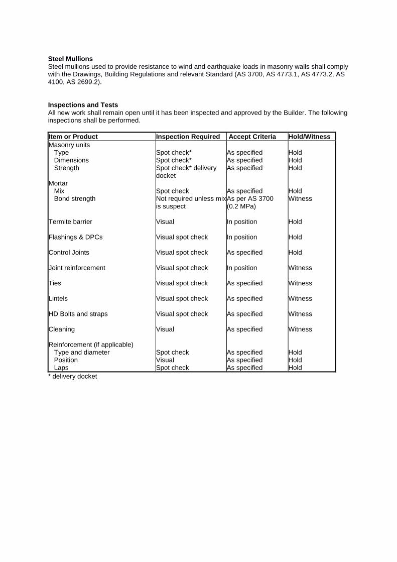
Steel Mullions Steel mullions used to provide resistance to wind and earthquake loads in masonry walls shall comply with the Drawings, Building Regulations and relevant Standard (AS 3700, AS 4773.1, AS 4773.2, AS 4100, AS 2699.2). Inspections and Tests All new work shall remain open until it has been inspected and approved by the Builder. The following inspections shall be performed. Item or Product Inspection Required Accept Criteria Hold/Witness Masonry units Type Dimensions Strength Mortar Mix Bond strength Termite barrier Flashings & DPCs Control Joints Joint reinforcement Ties Lintels HD Bolts and straps Cleaning Reinforcement (if applicable) Type and diameter Position Laps
Spot check* Spot check* Spot check* delivery docket Spot check Not required unless mix is suspect Visual Visual spot check Visual spot check Visual spot check Visual spot check Visual spot check Visual spot check Visual Spot check Visual Spot check
As specified As specified As specified As specified As per AS 3700 (0.2 MPa) In position In position As specified In position As specified As specified As specified As specified As specified As specified As specified
Hold Hold Hold Hold Witness Hold Hold Hold Witness Witness Witness Witness Witness Hold Hold Hold
* delivery docket