specification for dispersion slope compensating … for dispersion slope compensating module for ......
TRANSCRIPT

Specification for Dispersion Slope Compensating Module for
TW-RS Transmission Fiber in the C-band
TWRS-DK
Version 1.12 – 2015-09-09

OFS TWRS-DK Specification
1 Ordering information Order code format: The following table lists the nominal dispersion for the various compensation lengths: Compensated fiber length [km]
Nominal Dispersion 1550 nm [ps/nm]
Order Code
20 -90 TWRSDK_S_020-yy-zz 40 -180 TWRSDK_S_040-yy-zz 60 -270 TWRSDK_S_060-yy-zz 80 -360 TWRSDK_S_080-yy-zz
100 -450 TWRSDK_S_100-yy-zz 120 -540 TWRSDK_S_120-yy-zz 140 -630 TWRSDK_S_140-yy-zz 160 -720 TWRSDK_S_160-yy-zz 180 -810 TWRSDK_S_180-yy-zz 200 -900 TWRSDK_S_200-yy-zz 220 -990 TWRSDK_S_220-yy-zz 240 -1080 TWRSDK_S_240-yy-zz 260 -1170 TWRSDK_S_260-yy-zz 280 -1260 TWRSDK_S_280-yy-zz 300 -1350 TWRSDK_S_300-yy-zz
Custom compensation lengths available on request ‘yy’ in order code reflects choice of connectors:
Connector code Connector type 01 LC/PC connectors, 0.9 mm cable 02 SC/UPC connectors, 2.7 mm cable 03 FC/APC connectors (wide key), 3 mm cable 04 FMU/UPC connectors, 1.7 mm cable 05 SC/APC connectors, 3 mm cable 06 LC/APC connectors, 0.9 mm cable 07 SC/APC connectors, 0.9 mm cable 08 FC/APC connectors (narrow key), 0.9 mm cable 09 E2000 connectors, 2.7 mm cable 10 FC/PC connectors, 3 mm cable Other connector types available on request
‘zz’ in order code reflects choice of mechanical solution (see section 4 for details)
Mechanical code Mechanical package 01 Standard spool 10 Standard DSCM box Other spool sizes and DSCM box types available on request
Example: TWRSDK_S_180-01-01: DSCM for compensation of 180 km TWRS, with LC/FC connectors, standard spool.
TWRSDK-S-xxx-yy-zzMechanical option
Connector option
Compensation length [km]

OFS TWRS-DK Specification
1.1 Rack for mounting standard DSCM box: The standard box can be rack mounted in a 19” or 21” rack with the following rack mounts:
Order code Rack type DSCM-Rack-19-1 19” rack mount DSCM-Rack-21-1 21” rack mount
See section 4 for details and drawings.
2 Operating and Storage Conditions
2.1 Operating and Storage Temperature & Humidity Item Symbol Min Max Unit
Environmental operating temperature TOP -5 +70 °C
Environmental operating (relative) humidity XOP 5 85 %
Environmental storage temperature TST -40 +70 °C
Environmental storage (relative) humidity XST 5 85 %
2.2 Operating Wavelength Range The operating wavelength range of the TWRS-DK DSCM modules is 1530 nm – 1565 nm
2.3 Absolute Maximum Ratings Applicable for the full operating temperature range TOP without causing irreversible damage to the module. Item Symbol Max Unit Remarks Total optical input power PTOT 23 dBm Connector face is clean

OFS TWRS-DK Specification
3 Optical Properties This section describes the optical properties of the TWRS-DK DSCM. Unless otherwise stated, all parameters are valid EOL, over temperature and wavelength.
3.1 Residual Dispersion The residual dispersion RD is defined as
( ) ( ) ( )λλλ DSCMTWRS DDRD += , with
( ) λλ 045.025.65 +−=LEAFD , where λ is the wavelength in units of nm. The dispersion model above leads to a dispersion of 4.5 ps/nm/km and a slope of 0.045 ps/nm2/km at 1550 nm. The table below shows the residual dispersion spec of the TWRS-DK DSCM
Nominal Compensation Length [km]
Residual Dispersion BOL RT
[ps/nm/km]
Residual Dispersion EOL over temperature
[ps/nm/km] All modules ±0.20 ±0.22
The typical residual dispersion is shown in the figure below:
-0.30
-0.20
-0.10
0.00
0.10
0.20
0.30
1530 1535 1540 1545 1550 1555 1560 1565
Wavelength [nm]
Res
idua
l dis
pers
ion
[ps/
nm/k
m]
Figure 1: Typical residual dispersion for TWRS-DK DSCMs

OFS TWRS-DK Specification
3.2 Dispersion The following table defines the dispersion characteristics of the TWRS-DK DSCMs:
Nominal Compensation Length [km]
Dispersion @ 1530 nm BOL RT [ps/nm]
Dispersion @ 1550 nm BOL RT [ps/nm]
Dispersion @ 1565 nm BOL RT [ps/nm]
min typical max min typical max min typical max 20 -76.0 -73 -68.0 -94.0 -88 -86.0 -107.5 -104 -99.5 40 -152.0 -145 -136.0 -188.0 -177 -172.0 -215.0 -208 -199.0 60 -228.0 -218 -204.0 -282.0 -265 -258.0 -322.5 -312 -298.5 80 -304.0 -290 -272.0 -376.0 -354 -344.0 -430.0 -416 -398.0
100 -380.0 -363 -340.0 -470.0 -442 -430.0 -537.5 -520 -497.5 120 -456.0 -435 -408.0 -564.0 -531 -516.0 -645.0 -624 -597.0 140 -532.0 -508 -476.0 -658.0 -619 -602.0 -752.5 -728 -696.5 160 -608.0 -580 -544.0 -752.0 -708 -688.0 -860.0 -832 -796.0 180 -684.0 -653 -612.0 -846.0 -796 -774.0 -967.5 -936 -895.5 200 -760.0 -725 -680.0 -940.0 -885 -860.0 -1075.0 -1040 -995.0 220 -836.0 -798 -748.0 -1034.0 -973 -946.0 -1182.5 -1144 -1094.5 240 -912.0 -870 -816.0 -1128.0 -1061 -1032.0 -1290.0 -1248 -1194.0 260 -988.0 -943 -884.0 -1222.0 -1150 -1118.0 -1397.5 -1352 -1293.5 280 -1064.0 -1016 -952.0 -1316.0 -1238 -1204.0 -1505.0 -1456 -1393.0 300 -1140.0 -1088 -1020.0 -1410.0 -1327 -1290.0 -1612.5 -1560 -1492.5
Nominal Compensation Length [km]
Dispersion @ 1530 nm EOL over temperature
[ps/nm]
Dispersion @ 1550 nm EOL over temperature
[ps/nm]
Dispersion @ 1565 nm EOL over temperature
[ps/nm] min max min max min max
20 -76.4 -67.6 -94.4 -85.6 -107.9 -99.1 40 -152.8 -135.2 -188.8 -171.2 -215.8 -198.2 60 -229.2 -202.8 -283.2 -256.8 -323.7 -297.3 80 -305.6 -270.4 -377.6 -342.4 -431.6 -396.4
100 -382.0 -338.0 -472.0 -428.0 -539.5 -495.5 120 -458.4 -405.6 -566.4 -513.6 -647.4 -594.6 140 -534.8 -473.2 -660.8 -599.2 -755.3 -693.7 160 -611.2 -540.8 -755.2 -684.8 -863.2 -792.8 180 -687.6 -608.4 -849.6 -770.4 -971.1 -891.9 200 -764.0 -676.0 -944.0 -856.0 -1079.0 -991.0 220 -840.4 -743.6 -1038.4 -941.6 -1186.9 -1090.1 240 -916.8 -811.2 -1132.8 -1027.2 -1294.8 -1189.2 260 -993.2 -878.8 -1227.2 -1112.8 -1402.7 -1288.3 280 -1069.6 -946.4 -1321.6 -1198.4 -1510.6 -1387.4 300 -1146.0 -1014.0 -1416.0 -1284.0 -1618.5 -1486.5

OFS TWRS-DK Specification
3.3 Insertion loss
Nominal Compensation Length [km]
Insertion Loss BOL RT [dB]
Insertion EOL over temperature [dB]
Max Wavelength Dependent Loss [dB]
min max min max BOL RT EOL temp 20 0.5 1.7 0.5 2.2 0.30 0.40 40 0.8 2.2 0.8 2.7 0.30 0.40 60 1.0 2.8 1.0 3.3 0.30 0.40 80 1.2 3.3 1.2 3.8 0.35 0.45
100 1.5 3.8 1.5 4.3 0.35 0.45 120 1.7 4.4 1.7 4.9 0.40 0.50 140 1.9 4.9 1.9 5.4 0.45 0.55 160 2.2 5.4 2.2 5.9 0.50 0.60 180 2.4 6.0 2.4 6.5 0.55 0.65 200 2.6 6.5 2.6 7.0 0.60 0.70 220 2.9 7.0 2.9 7.5 0.65 0.75 240 3.1 7.6 3.1 8.1 0.70 0.80 260 3.3 8.1 3.3 8.6 0.75 0.85 280 3.6 8.6 3.6 9.1 0.75 0.85 300 3.8 9.2 3.8 9.7 0.80 0.90
3.4 Polarization Effects
Nominal Compensation Length [km]
PMD [ps] PDL [dB]
typical max max 20 0.09 0.30
0.1
40 0.13 0.40 60 0.16 0.50 80 0.18 0.55
100 0.20 0.60 120 0.22 0.65 140 0.24 0.75 160 0.26 0.80 180 0.27 0.80 200 0.29 0.85 220 0.30 0.90 240 0.32 0.95 260 0.33 1.00 280 0.34 1.05 300 0.35 1.05
OFS TWRS-DK Specification
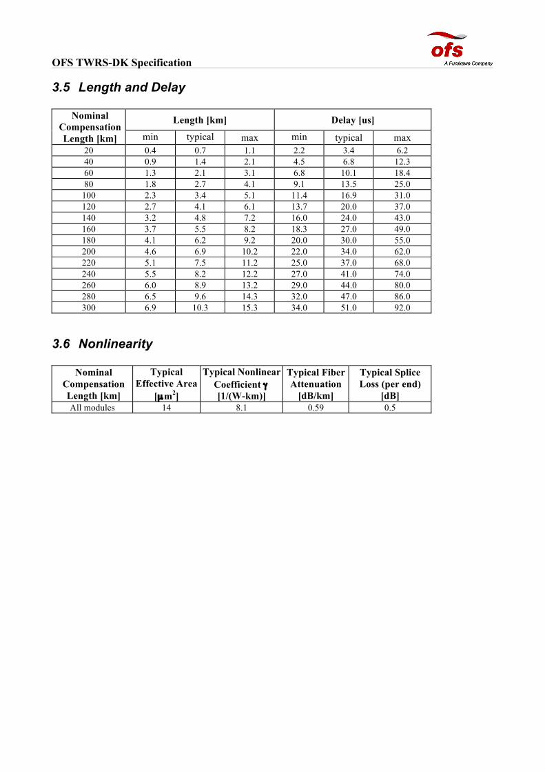
3.5 Length and Delay
Nominal Compensation Length [km]
Length [km] Delay [us]
min typical max min typical max 20 0.4 0.7 1.1 2.2 3.4 6.2 40 0.9 1.4 2.1 4.5 6.8 12.3 60 1.3 2.1 3.1 6.8 10.1 18.4 80 1.8 2.7 4.1 9.1 13.5 25.0
100 2.3 3.4 5.1 11.4 16.9 31.0 120 2.7 4.1 6.1 13.7 20.0 37.0 140 3.2 4.8 7.2 16.0 24.0 43.0 160 3.7 5.5 8.2 18.3 27.0 49.0 180 4.1 6.2 9.2 20.0 30.0 55.0 200 4.6 6.9 10.2 22.0 34.0 62.0 220 5.1 7.5 11.2 25.0 37.0 68.0 240 5.5 8.2 12.2 27.0 41.0 74.0 260 6.0 8.9 13.2 29.0 44.0 80.0 280 6.5 9.6 14.3 32.0 47.0 86.0 300 6.9 10.3 15.3 34.0 51.0 92.0
3.6 Nonlinearity
Nominal Compensation Length [km]
Typical Effective Area
[µm2]
Typical Nonlinear Coefficient γ [1/(W-km)]
Typical Fiber Attenuation
[dB/km]
Typical Splice Loss (per end)
[dB] All modules 14 8.1 0.59 0.5

OFS TWRS-DK Specification
4 Mechanical Design The standard TWRS-DK DSCMs are available in two mechanical options Option code Description Dimensions Drawing no 01 Fibre spool Ø210 mm x 38 mm rv_sys20_spol_114_210_38_04_d 10 Standard box 224 mm x 238 mm x 45 mm rv_sys04_k02_asm01_00_d Furthermore, a rack mount that allows two modules to be mounted in a 19” rack is also available (ordered separately).
Order code Rack type Drawing no DSCM-Rack-19-1 19” rack rv_sys04_k02_asm01_00_d.pdf DSCM-Rack-21-1 21” rack
4.1 Reference Spool Drawing

OFS TWRS-DK Specification 4.2 Reference Box and Rack Drawing
5 Test Data Detailed test data in paper/and or electronic format can be supplied, including the following
• IL @ 1550 nm • IL over operating wavelength range • WDL • Dispersion @1530, 1550 and 1565 nm • Max absolute residual dispersion • PMD
6 List of Acronyms BOL Beginning of life DSCM Dispersion slope compensating module EOL End of life PDL Polarization dependent loss PMD Polarization mode dispersion RT Room temperature (~22 degrees Celsius) WDL Wavelength dependent loss (max-min over wavelength)
--- end of document ---