specification-driven structural testing of multi-tier web applications
TRANSCRIPT

Specification-Driven Structural Testing of Multi-Tier Web Applications
Xiaoyu Zheng Amazon.com
705 5th Ave. S, Seattle, WA 98109
206-266-3647 [email protected]
Mei-Hwa Chen Computer Science Department
SUNY at Albany, Albany, NY 12222
518-442-4283 [email protected]
ABSTRACT Large scale, multi-tier web applications are inherently dynamic, complex, and heterogeneous. Testing such emerging applications is challenging yet critical. First, because of inter-tier interactions, a fault in one tier may propagate to the others; while each tier is often implemented and maintained by a designated team, detailed cross-tier information may not be available to the other teams. Second, dynamic pages, generated by backend software at runtime, have been largely used to fulfill interactive service requests. Exhaustively testing all the dynamic pages is neither practical nor feasible. Effective testing of multi-tier web applications requires a coherent model to capture the dependence relationships caused by the cross tier interactions and to provide some mechanisms for exploring dynamic pages. Existing models for structural testing of web applications have not been able to address these challenges; thus prevalent testing approaches employed by industry are mostly based on black box testing, whose effectiveness is often restrained by lack of complete specifications. Both black and white box approaches have their limitations and they can complement each other only if there exists an effective means to bridge the gap between the two. In this paper, we present a test model that synthesizes specifications and an inter-connection dependence model to guide the structural testing driven by specifications. We model the specifications by structuralizing use cases/scenarios and construct an interconnection model to capture inter-tier dependence relationships which are then rendered by using DOM-like summary Web GUI Trees. The structure of the specifications is conformed to that of the summary WGUI trees, which enables test cases to be derived from the specifications and be easily extended to cover dependence relationships. Our test model depicts inter-tier dependence relationships and displays the constructs of all the dynamic pages and the dependence relationships between the constructs; hence it can be used to create viable test cases to exercise sequences of web pages containing plausible cross-tier faults. We demonstrate the application of the test model with two case studies and show promising results obtained from testing the two industrial web applications. Keywords Web applications, system dependence graph, structural testing, use cases.
1. INTRODUCTION Web applications, which use the World Wide Web (WWW) as a means for providing services, have been dramatically adopted in a wide range of software application domains. To support fast growing demands for various services, web applications have become more and more complex, dynamic, and heterogeneous. The three-tier architecture of web applications emerged in the 1990s; normally, they are referred to as the presentation, the logic, and the data tiers. The presentation tier presents web user interfaces in client browsers based on html files received from web servers. These html files can be static files or dynamically generated based on the information/service on demand; because dynamic pages support dynamic configurations providing greater flexibility, they have become much more attractive than static pages. The logic tier is responsible for processing business logic, which can be implemented by using various programming languages, such as Java, C/C++, perl, etc. The data tier is used to hold enterprise information that may be shared by multiple applications and to provide data to the logic tier; the data may be saved in a database management system and/or configuration files. In large-scale web applications, components in each tier are usually developed, tested and maintained by different teams on separate platforms; hence they are usually loosely coupled with the ones in other tiers to increase reusability and to facilitate dynamic integration.
Although this multi-tier architecture eases the development of complex web applications, it also introduces new challenges to testing. First, because of the heterogeneous and distributed nature of web applications, testing relies mainly on individual tier-based testing. For example, there are many commercial tools for HTML validation at the client side, and for link
1

checking and load/performance testing at the server side. However, during an execution of a web application, the information flows from the client-side web interface to the server-side logical processing components, then to the back-end database server, and the results traverse back to the client side. With this type of information flow, dependencies exist not only within each tier, but also between tiers. A fault residing in one tier may propagate to other tiers; therefore, to cope with the impact of cross tier faults, testing needs to account for the inter-tier interactions. On one hand the individual tier-based testing does not pay attention to cross tier dependences and often overlooks this type of fault. On the other hand, the integration testing lacks detailed information on each component; it is difficult to cover all fault sensitive paths with limited resources. Testing multi-tier web applications has a need for an integrated model rendering both intra- and inter-tier interactions. This model is essential for identifying fault-sensitive paths in order to exercise the parts of the application that may contain cross-tier faults. However, dealing with the complexity of a complete integrated model may be overwhelming and may produce non-optimum results due to misunderstandings or shortage of time or resources.
Second, dynamic web applications have been widely adopted to support the growing complexity of on-line services. Dynamic web interfaces are generated at run time based on the users’ inputs. These dynamically generated GUIs are varied due to different user interactions, or changes in configuration data or in system environment. Further, a typical web page often contains a number of hyperlinks for navigating to targeted pages, and each of those pages may have many hyperlinks as well. To reach a designated page, there may be an exponentially large number of different paths, and the content of the designated page may depend on the path leading to the page. When testing web applications with the presence of the dynamic pages it can be extremely expensive, if it is even feasible, to cover the entire set of web pages.
With the growing demands and increasing complexity of web applications, testing is essential to ensure that web applications provide reliable services. Black box testing using specifications to create test cases, which are directly derived from the expected operational usage, has been commonly adopted by industry. Because it highly depends on the rarely achieved completeness and correctness of specifications, this type of testing is often insufficient and requires additional efforts to ensure the quality of the applications. To detect code-based faults, white box based structural testing is generally recommended. This type of testing depends on thoroughly exercising the source code of the application to some extend in order to reveal coding defects; it guides test case generation by using selected coverage criteria, such as statements, conditions, def-use associations, and paths. The stronger the criterion (w.r.t. fault detectability) used, the greater the effort required for analysis. Both black and white box approaches have their strengths and limitations. Although it has been suggested that they be used together to complement each other, there has not been found an effective means to integrate the two approaches. On one hand, testing web applications with the existing approaches for modeling web applications does not include all three tiers; thus structural testing cannot be adequately performed due to the lack of complete structure information and an appropriate representation of test interfaces. On the other hand, there is no standard way to document the specifications; informal natural languages and semi-formal use cases are commonly employed but there are still gaps between the specifications and the implementations. This makes the integration of the specification-based black box testing and the white box structural testing difficult.
To overcome these testing challenges, we develop a coherent model that computes inter-connection information across all the tiers to obtain both intra- and inter-tier dependence relationships and renders this critical information by using summarized DOM-like Web Graphical User Interface (WGUI) trees. The nodes of the summary WGUI trees represent web objects and their attributes, which are the building blocks of all the web pages including both static and dynamic pages. The edges indicate the navigation, control and data dependence relationships between web objects and pages. Based on the summary WGUI trees, we propose four coverage criteria: web objects, links, data dependence edges, and data constraints to guide effective and efficient testing. The structural testing based on the summary WGUI trees has several advantages. First, test inputs can be derived directly from the attribute nodes of web objects. Second, by covering all the web objects, the constructs (templates) of the web pages will be exercised at least once to validate the look and feel of the web pages. Third, web pages that have data/control dependence relationships will be tested in a designated order steered by the link and the data dependence edges. Thus, fault-sensitive paths will be selected and tested. Furthermore, we model the specifications by adapting use case analysis and providing step-wise structuralized descriptions of the flow of events, which conform to the structure of the summary WGUI trees, hence facilitating a smooth integration of the specifications and the dependence models of the applications. With this integration, data inputs can be derived directly from the specifications and be fed to the summary WGUI trees for execution, and then test cases can be extended easily to cover unexercised web objects, links, data dependence edges and the constraints on the inputs. We conducted empirical studies spanning two application domains, including an e-commerce system and a bioinformatics application. We observed that although each system has a different focus on the tiers, testing based on the summary model shows promising results for fault detection in both studies.
2

The remainder of this paper is organized as follows. In Section 2, we review the existing techniques for testing web applications. Section 3 presents the modeling of multi-tiered web applications. In section 4 we describe the testing methodology proposed in this paper. Section 5 shows the empirical studies, and we give our conclusions in Section 6.
2. MODELING MULTI-TIER WEB APPLICATIONS Multi-tier web applications are by nature heterogeneous. Each tier consists of components implemented in the language suitable for the tier and are loosely coupled with those written in different languages and reside in the other tiers. To model this heterogeneous architecture, first, the dependence relationships in each tier need to be modeled with the constructs that can best describe the features of the language used in the tier. Then the inter-tier interactions need to be modeled based on the nature of the interaction to integrate the intra-tier models into an integrated model. Finally, the complexity of the integrated model must be reduced to attain simplicity. To this end, our model is constructed through three phases. In phase 1, the focus is on each individual tier to construct intra-tier dependence models. We construct the presentation by using Web GUI (WGUI) trees for server pages and the data tiers by using Data Object trees for databases or XML files. The modeling of the logic tier can be adopted from the existing dependence models for traditional programs or for object-oriented programs depending on the language used in this tier. The second phase is to integrate the intra-tier models into an inter-connection model. The final phase begins by computing the transitive closures of dependences across the tier boundaries. Then, the resultant summary dependence edges are added to the WGUI trees rendering both direct and indirect dependence relationships between web objects and between web pages. Based on the summary WGUI trees, testing can more effectively select fault prone paths and create test inputs.
The details of the model are given in the following sections and we use an example to demonstrate the construction of the model. The example is a course management system that has two types of users, students and instructors. Both of them need to login to access their course information; students can only view their own score in a course and the instructor can view and modify all students’ scores. The application is built in a tiered architecture: the presentation tier is written in html with embedded Perl code, the logic tier is pure Perl code handling database interfaces and business logics, and in the data tier we use the SQL 2000 database to save content data such as students’ scores, and an xml file to save control data such as permissions for accessing the database. The complete source code and the corresponding model can be found in [29].
2.1 Intra-tier dependence modeling
2.1.1 Modeling the presentation tier The presentation tier of web applications consists of server page programs running on the server side to generate html pages. The server pages can be implemented by using a variety of languages, such as ASP, JSP, PHP, Perl, etc., which share a common html based structure with embedded logics for dynamic generation of html statements. These logics may be located in a special section of the server page or interleave with html code. Figure 1 shows a server page in the example system, which is a login page containing a form for users to submit their user names and passwords. If a user has already logged in, the page will display a warning message first and then display the login form showing the current login user name; otherwise it will just display a blank login form. The page is written with html code and three Perl statements at lines 2, 3, and 4, respectively. 01 <hr><h1>Login</h1><hr> 02 % my $uname; 03 % if ($session) { 04 % $uname = $session; 05 <font color="red">You are currently login as <% $uname %>, you may want to logout first? </font> <br /> <br /> 06 % } 07 <form name="login" action="auth.html" method=post align="center"> 08 Username: <input type="text" name="uname" value= <% $uname %> ><br /><br /> 09 Password: <input type="PASSWORD" name="passwd"><br /> 10 <br /> 11 <input type="submit" onclick="auth.html" value="login"><br /> 12 </form>
Figure 1. Example 1: Login.pl.
3

Ricca and Tonella presented system dependence models for slicing web applications [23] [24] Their dependence models depict four types of relationships: control, call, data, and semantic dependences among server-side scripts. These models are constructed mainly within the presentation tier, their modeling of server pages adopted from the traditional control flow and dependence models, which does not address the presentation structure and information. For example, a node representing a line of server page statement does not render its expected outcome on the web page. However, most web application tests are executed against web GUIs; with the existing models, testing will require additional effort in test case generation and execution. Figure 2 shows a system dependence graph of Example 1 by using the existing approaches [23] [24].
Figure 2. An SDG of Example 1.
To reduce such efforts, our approach is to make use of the structure of the html document to construct the dependence graph, which can be used directly to guide the creation of test inputs. We adopt the notion of Document Object Model (DOM) [28] , a standard model developed by W3C. DOM is language neutral and there are a number of parsers available that can be easily customized to construct our model for the presentation tier. The DOM defines a standard set of objects for HTML, and a standard way to access and manipulate HTML documents. The DOM views HTML documents as a tree structure of elements. All elements, along with their text and attributes, can be accessed and manipulated through the DOM tree. Figure 3 shows a DOM tree of Example 1.
ActionName
hr
Input
Form
Login
Font
InputInput
Figure 3. A DOM tree of Example 1.
Nevertheless, a standard DOM tree does not include any logic code and thus cannot represent a server page with embedded logic code. To encompass the information of the embedded logic, we augment a DOM tree with statement nodes denoting the logic statements and three types of dependence edges connecting the two types of nodes to form a WGUI tree that can depict the dependence relationships on a server page. The nodes and the edges are described in the following. Document node: A document node represents the structure of an html statement; each document node denotes one web object or one attribute of the web object. A composite document node has one or more child nodes, while a primitive node is a leaf node in the WGUI tree indicating a primitive attribute of its parent node. Document nodes are rendered as ellipse nodes in Figure 4. Statement node: A statement node represents the embedded logic code in the server page. Each statement node denotes one statement of the embedded code. These statements do not represent any web objects or any of their attributes in the web pages, but they may carry the dependence relationships with web objects or their attributes, which then can be used to derive
4

dependence relationships between web objects or attributes. Statement nodes are rendered as circle nodes in Figure 4. For example, line 3 in Example 1 is represented as node 3 in Figure 4. Note that two virtual nodes, v9 and v9, are added in Figure 4 to indicate actual-in nodes associated with the attribute node “Action” that is an analogy of a callsite node.
F F
Figure 4. A WGI tree of Example 1.
Control dependence edge: control dependence edges in traditional dependence models are used to connect the predicate evaluated at a conditional or loop statement to the statements depending on the Boolean value of the predicate. In our model, the notion of control dependence edges between statement nodes is the same as in the traditional dependence models. A control dependence edge connects two document nodes if one defines a domain that includes the other; for example, in Figure 1, since the ‘Form’ object includes all the three ‘Input’ objects, and the two attributes: ‘name’ and ‘action’, consequently there are three control dependence edges connecting the Form node (node 7) to each of these document nodes (nodes 8, 9, and 11). A control dependence edge connects a statement node to a document node if the statement node is a conditional or loop statement that decides the display of the document node. For example, line 3 is a conditional statement that decides whether the object ‘font’ will be displayed or not, so there is a control dependence edge between node 3 (line 3) and node 5 (the object Font). Similar to the control dependences in traditional dependence graphs, we annotate the value of the conditions on the control dependence edges to indicate the branch that the dependent code resides, e.g., statement node 4 and document node 5 are both in the false condition branch of statement node 3, so we marked ‘F’ on the dependence edges from node 3 to node 4 and to node 5. Link dependence edge: The execution paths of a web application are decided in the runtime by users’ actions; for example, when a user clicks the submit button in example 1, the auth.html page, which authenticates the login information, will be generated and displayed. The relation between the submit button and the authentication page is similar to a function call. They are different in the way that in a function call, the callee will be invoked when the call site is reached by the execution, whereas during the execution of the web application, when the submit button is displayed the auth.html will be generated only if the user clicks on the submit button. Thus, a link dependence edge connects a document node to the root node of a server page if the document node defines an attribute that will lead the user to the server page when the user performs the corresponding action. Parameter-in: A parameter in dependence edge connects an actual-in document node to a corresponding formal-in statement node of a WGUI tree if the document node’s value is used as the parameter defined by the formal-in node. Parameter-out: A parameter out dependence edge connects a formal-out statement node to a corresponding statement or document node if the formal-out node defines the return value that is used by the corresponding statement node or document node. Note that unlike traditional function calls, a server page itself never returns values, and the functions defined in the server page can never be invoked by other server pages, so this type of edge only exists between a statement node and another statement node or document node within the same server page, or between client-side scripts, such as JavaScript. Data dependence edge: Data dependences for traditional programs hold when a statement defines the value of a variable, which is used at another statement that can be reached via a definition clear path. We keep this notion for dependences
5

between statement nodes, and extend the definition to document nodes. In a server page a variable can be defined in a logic statement and used by an html statement, so a data dependence edge holds between a statement node and a document node if the statement node defines a variable that is used to set the value of the document node, or vice versa. For example, in the login.html page, line 4 defines $uname variable, which is used to set the value attribute of input ‘uname’, so there is a data dependence edge from statement node 5 to document node value. This WGUI model has several advantages: first, testing based on web objects constituting every web page provides a means to explore every possible display on the pages. Second, the dependence edges provide a useful guide for selecting fault sensitive paths that are likely to have faults caused by data dependencies. Third, it directly models the look of the GUI, which makes test generation much easier as compared to modeling from the source code of html files. Fourth, the outcome of an execution of a web application is a web page containing a number of objects. To validate the result of a test, checking all the web objects may be tedious when there are many objects in a page. With this WGUI model, only those relevant objects depicted through the dependence edges need attention, and this will greatly simplify the validation process.
2.1.2 Modeling the logic tier The logic tier is responsible for all the computation logics, and it can use any programming languages including procedural languages, scripting languages, object-oriented languages, or components developed in-house or COTS. A number of system dependence graphs have been developed. For procedural programs, the inter-procedural system dependence graph proposed by Horwitz, Reps, and Binkly [10] has been well developed. For object-oriented programs, Larsen and Harrold proposed a dependence grap [12] and later Liang and Harrold presented an improved version [13]. Allen and Horwitz [2] proposed a dependence graph taking into account exceptions in Java programs. We have developed a tool, JATO [15], that performs dataflow analysis and constructs system dependence graphs for Java programs. For component-based systems, we have developed a hierarchical system dependence graph including method, operation, interface, component, and system five levels of dependence graphs [20]. Depending on the programming language used, an appropriate system dependence model can be adopted.
A System Dependence Graph is represented as a graph <V, E> with each node in V representing a statement, and each edge in E representing a dependence relationship between two statements. The types of edges include control dependence, data dependence, call dependence and parameter in/out dependence. A control dependence edge reflects a program’s nesting structure and data dependence indicates the sequence of data definition and usage. Data dependence has two sub-types: flow dependence indicates the define-use order, and def-order dependence indicates the define-define order. Call dependence and parameter in/out dependence are used together to describe the calling context of functions. Figure 5 shows an example logic program, list_score.pl, written in Perl and Figure 6 shows its corresponding dependence graph, where lines 2 and 3 are parameter-in nodes defining $cnum and $term, which are used at line 8 to retrieve score information, so there are two data dependence edges from nodes 2 and 3 to node 8 01 <%args> 02 $cnum => 'cnum' 03 $term => 'term' 04 </%args> 05 <%perl> 06 my $dbh = DBI->connect('DBI:ODBC:Demo', 'sa', 'password') or die "Couldn't connect to database: " . DBI->errstr; 07 my $sth = $dbh->prepare('SELECT uname, score FROM user_course WHERE course_number = ? and term = ? and type = \'student\' ') or die "Couldn't prepare statement: " . $dbh->errstr; 08 $sth->execute($cnum, $term); 09 my @harray; 10 while ( my $hash = $sth->fetchrow_hashref() ) { 11 push(@harray, $hash); 12 } 13 return @harray; 14 </%perl>
Figure 5. Example 2: list-score.pl.
6

Figure 6. An SDG of Example 2.
2.1.3 Modeling the data tier Because of the heterogeneous and distributed nature of web applications, external data are widely used as the communication media between different platforms or different applications. Usually these external data persist in the external device and can be shared by multiple applications or different web pages in one application. The data tier manages these data and stores them in databases and/or xml files. Therefore, the data used by one application may be defined by other applications or manually via database access tools or editors. The existing dependence models do not include the external data. We model the data tier for the following reasons. (1) Modeling data tier will help us analyze the impact of these external actions on the application and vice versa. (2) In a web application, the execution paths depend on users’ actions, and since each web page can be reached directly by typing the URL in a web browser, any execution path would be technically possible; as a consequence, analyzing dependence relationships on every possible path would not be practical. By modeling the data tier, we can tackle this difficulty by analyzing the dependence relationships between each individual server page and the external data first and then use these relationships to analyze dependences between sever pages. With this approach, the computation complexity for analyzing dependences can be significantly reduced.
The data tier is modeled based on the structure level, such as database schema for database tables, or xml schema for xml files. The data stored in this tier are modeled by using data objects represented by Data Object Trees (DOTs). A DOT is a directed tree, which includes three types of nodes. (1) A root node represents the name as the identity of the data object; (2) a non-leaf node represents the complex type attributes of the object; and (3) A leaf node represents the simple type attribute of the object. The nodes are connected via two types of edges: control dependence edges and data dependence edges.
Complex type node: A complex type node represents an element that contains other elements and/or attributes. For example, line 2 in Figure 7.1 indicates that the node represented by line 1 is a complex type, which contains five sub elements defined at lines 4, 11, 18, 25, and 32, respectively.
Simple type node: A simple type node represents an element that contains only a value or a text, or just an attribute. For example, line 5 in Figure 7.2 indicates that the node representing line 4 is a simple type node that contains only a string value.
Control dependence edge: a control dependence edge connects two DOT nodes if the element represented by one node defines a domain that includes the one represented by the other.
Data dependence edge: a data dependence edge connects a DOT node A to a DOT node B if every piece of data in B has a corresponding data in A, that is, a change of the value of A will force a change on B. This type of dependence includes the foreign key relation in relational databases and key reference element in an xml schema.
The example shown in the following demonstrates the construction of DOTs from database and xml schemas. We use XSD schema to represent both database and xml schema. Figure 7.1 and 7.2 list the schemas that define the database tables “user_course” and “users”. The figures show the complete schemas, but we only need the information on simple type element level; for example, in Figure 7.1 at line 1 the user_course element is a complex type element defined at line 2, and it defines a domain from line 1 to line 41 including all five of its sub elements, uname, course_number, term, score, and type. Line 27 in users table schema defines a primary key ‘unamePK’ that is used in user_course table as the foreign key for ‘unameFK’ (line 41), A data dependence edge from uname node in users table to uname node in user_course table is added to the DOTs shown in Figure 8.
7

01 <xsd:element name="user_course"> 02 <xsd:complexType> 03 <xsd:sequence> 04 <xsd:element name="uname" minOccurs="0" od:jetType="text" od:sqlSType="nvarchar"> 05 <xsd:simpleType> 06 <xsd:restriction base="xsd:string"> 07 <xsd:maxLength value="50"/> 08 </xsd:restriction> 09 </xsd:simpleType> 10 </xsd:element> 11 <xsd:element name="course_num" minOccurs="0" od:jetType="text" od:sqlSType="nvarchar"> … 17 </xsd:element> 18 <xsd:element name="term" minOccurs="0" od:jetType="text" od:sqlSType="nvarchar"> … 24 </xsd:element> 25 <xsd:element name="score" minOccurs="0" od:jetType="text" od:sqlSType="nvarchar"> … 31 </xsd:element> 32 <xsd:element name="type" minOccurs="0" od:jetType="text" od:sqlSType="nvarchar"> … 38 </xsd:element> 39 </xsd:sequence> 40 </xsd:complexType> 41 <xsd:keyref name="unameFK" refer="unamePK"> 42 <xsd:selector xpath="//users/uname"/> 43 <xsd:field xpath="@user_course/uname"/> 44 </xsd:keyref> 45 </xsd:element>
Figure 7.1. Example 3: the database schema for the user_course table
01 <xsd:element name="users"> 02 <xsd:complexType> 03 <xsd:sequence> 04 <xsd:element name="uname" minOccurs="0" od:jetType="text" od:sqlSType="nvarchar"> 05 <xsd:simpleType> 06 <xsd:restriction base="xsd:string"> 07 <xsd:maxLength value="50"/> 08 </xsd:restriction> 09 </xsd:simpleType> 10 </xsd:element> 11 <xsd:element name="passwd" minOccurs="0" od:jetType="password" od:sqlSType="nvarchar"> … 17 </xsd:element> 18 <xsd:element name="type" minOccurs="0" od:jetType="text" od:sqlSType="nvarchar"> … 24 </xsd:element> 25 </xsd:sequence> 26 </xsd:complexType> 27 <xsd:key name="unamePK"> 28 <xsd:selector xpath=".//users"/> 29 <xsd:field xpath="@uname"/> 30 </xsd:keyref> 31 </xsd:element>
Figure 7.2. Example 4: the database schema for the users table
8

Figure 8. The DOTs of the user course table and the users table.
2.2 Integrating multi-tier dependence models The intra-tier dependence models presented in the previous section depict the dependence relationships within the boundary of each tier. To fulfill service requests, data and control flow back and forth between tiers in web applications. These inter-tier interactions induce inter-tier dependences, which can cause faults propagating from one tier to the others. These faults are difficult to detect without an integrated inter-tier dependence model. This section presents the process of integrating the intra-tier models into an integrated inter-tier dependence model based on their interconnection natures. We first integrate the presentation tier with the logic tier and then the resulting model is integrated with the data tier to form an Integrated N-tier System Dependence Graph (INSDG). 2.2.1 Integrating the presentation tier with the logic tier Server pages in the presentation tier are responsible for getting static pages or generating dynamic pages. In addition, the scripts in the server pages may invoke methods in the logic tier for complex computations. Meanwhile, the logic tier may also invoke the server page by directing users to the page. The connections between the presentation tier and the logic tier can be made through three types of edges: call dependence, parameter in/out, and link dependence edges. The first two types are similar to the ones in the traditional dependence models, and the third type is similar to the ones in WGUI trees. Call dependence edge: There are two types of call dependence between the presentation tier and the logic tier. The first type connects a statement node from the presentation tier to an entry node in the logic tier if the presentation tier node calls the function represented by the logic tier node. For example, line 6 of list-score.html, shown in Figure 11, calls the function list-score.pl, shown in Figure 12, so there is a call dependence edge between statement node 6 in list-score.html and the entry node of the SDG of list-score.pl. The second type connects a statement node from the logic tier to a document root node in the presentation tier if the execution of the statement node directs the web browser to the server page represented by the document root node. For example, in auth.pl shown in Figure 9, the application redirects the user to the select-course page if the login information is correct, otherwise redirects the user to the login error page. In this example line 15 calls a Mason Perl system function to redirect user to the select-course page, so there is a call dependence edge from node 15 in SDG of auth.pl to the root node of WGUI of select-course.html. 01 <%args> 02 $uname => 'uname' 03 $passwd => 'passwd' 04 </%args> 05 <%perl> 06 use Apache::DBI;
9

07 use CGI qw(:standard -debug); 08 my $dbh = DBI->connect('DBI:ODBC:Demo', 'sa', 'password'); 09 my $sth = $dbh->prepare('SELECT * FROM users WHERE uname = ?') or die "Couldn't prepare statement: " . $dbh->errstr; 10 $sth->execute($uname); 11 my $hash = $sth->fetchrow_hashref(); 12 my $dbpasswd = $hash->{password}; 13 if ($passwd eq $dbpasswd) { 14 $session = $uname; 15 $m->redirect('select-course.html'); 16 } else { 17 $session = ''; 18 $m->redirect('login-error.html'); 19 } 20 </%perl>
Figure 9. Example 5: auth.pl Parameter-in/out: A parameter-in dependence edge connects an actual-in document node to a corresponding formal-in node of a procedure/method if the document node’s value is used as the parameter passed to the formal-in node. For example, in Figure 12, the login form in the login page submits the value of document node 8:value to auth.pl as the parameter $uname, so there is a parameter-in dependence edge between 8:value document node, and the formal-in node 2 in auth.pl. Note that all the variables defined in the section enclosed by the two <%args> tags in Perl modules are used for accepting arguments, so we consider the nodes in the section as formal-in nodes. A parameter-out dependence edge connects a corresponding formal-out node to an actual-out document node that receives the return value. Link dependence edge: A link dependence edge connects a document node to a root node in the logic tier if the document node defines an attribute that leads the user to the logic function represented by the root node after the user performs the corresponding action. For example, in our previous example of login page (Figure 1), the password and the username are passed to auth.html, where the corresponding information will be displayed. An alternate way of implementation is to pass the password information to a logic tier function auth.pl directly and let the logic function redirect the user to the corresponding success or failed page based on their login info. In this case, the document node that represents the Action attribute of login form will have a link dependence edge to the root node of auth.pl, as shown in Figure 10.
Figure 10. An example of integrated presentation tier and logic tier dependence graph.
10

2.2.2 Integrating N-tier System dependence Graphs The second integrating phase is to combine the integrated presentation and logic tier dependence model with the data tier. This phase of integration takes into account all the three tiers; we refer it as n-tier integration to be general and extensible. The programs in the logic tier direct interact with the data tier via data passing, fetching and storing; thus the integration focus is mainly on the data flow between the tiers, i.e., the dependence graphs in the logic tier and the DOTs in the data tier are connected via data dependence edges. A data dependence edge between the logic tier and the data tier represents that a program in the logic tier invoked by a server page in the presentation tier defines/uses a piece of data stored in the data tier and there is no other define/use of the data from/to the entry/exit of the server page to/from the callsite of the program. This is because that each service request is made through the presentation tier and dataflow begins at the presentation tier. Furthermore, the defines and the uses of the persistent data stored in the data tier are not the same as those in memory data, the persistent data used by one application may be defined by other applications or by manually using an editing tool, and vice versa. To distinguish these differences we use external define and external use to represent the define and the use of the persistent data in the data tier and external data dependence edges to connect nodes in the logic and the data tiers with def-use associations. Details are given in the following.
Definition: A piece of external data is considered defined if its state is changed by a statement of an application or explicitly by using an editing tool.
Example 6. The following update sql statement defines the ‘score’ field of the user_course table
“Update user_course set score=’A’ where uname=’xiaoyu’;”
Example 7. The following Perl statement using XML::Simple module defines the ‘view’ element in the xml file shown in Figure 8.
“Doc->{“permissions”}{“permission”}{“view”} = 0;”
Definition: A piece of external data is considered used if its value is referenced, either by a statement or an editing tool.
Example 8. The following select sql statement uses the value from the score field in user_course table
“Select score from user_course where uname=’xiaoyu’”
Example 9. The following Perl statement uses the ‘view’ element from the xml file permission.xml
“$tmp = Doc->{“permissions”{“permission”{“view”}”
Besides the definition and use during program execution, external data can also be modified or referenced outside the lifetime of the program. These operations are outside the boundary of the program, but they can also affect or be affected by the execution of the program.
Definition: a piece of external data is externally defined with respect to a program if it is defined outside the lifetime of the program.
Example 10. A developer or a DBA executed the update sql query against the user_course table in example 6; this is an external define of the field ‘score’ of table user_course.
Example 11, if another application contains the above Perl statement that defines the score field of user_course table, this statement will externally define the score field.
Definition: a piece of external data is externally used with respect to a program if it is used outside the lifetime of the program
Similarly, if examples 8 and 9 occur outside the lifetime of our demo application, they will be considered as external use of the data. External data dependence
Because each web server page can be reached directly by typing the url from a web browser, we can treat each server page as a standalone program, whose lifetime spans from the user sending the url request to the web page being displayed on the
11

user’s web browser. The connections of the logic tier and the data tier are made through data dependence edges. A data dependence edge connects a DOT node and a statement node.
Definition: an external data dependence edge connects a DOT node to a statement node of an SDG of a logic tier program if the statement uses the data represented by the DOT node which are externally defined, and there is a definition-clear path from the entrance of the server page to the callsite of the program containing the statement.
For example, Figure 11 shows a list-score.html server page, which calls the function list-score.pl shown in Figure 12 to retrieve student scores; at line 8 it calls sql query to retrieve data from table user_course. And from the entrance of list-score.html to the callsite of the list-score.pl, which is line 06 in list-score.html, there is no any definition of the field score in table user_course, so we can draw an external data dependence edge from DOT node score in table user_course to the statement node 8 of list-score.pl, as shown in Figure 15.
Definition: an external data dependence edge connects a statement node of an SDG of a program in the logic tier to a DOT node if the statement defines the data represented by the DOT node which are externally used, and there is a definition clear path from the callsite of the program to the exit of the server page.
For example, Figure 13 shows an update-score.html server page, where update-score.pl shown in Figure 14 is called to modify student scores. Line 10 of the update-score.pl uses sql query to update the score field of the table user_course, and there is no any definition of the same field from the callsite of update-score.pl, which is line 8 in update-score.html, to the end of the html file, so there is an external data dependence edge from the statement node 10 of update-score.pl to the DOT node ‘score’ in user_course table, as shown in Figure 15. 01 <%args> 02 $cnum => 'cnum'; 03 $term => 'term'; 04 </%args> 05 <%perl> 06 my @harray = $m->comp('list-score.pl', cnum=>$cnum, term=>$term); 07 </%perl> 08 <TABLE border="1" align="center"> 09 <CAPTION><EM>Score list for <% $cnum %> </EM></CAPTION> 10 <TR> 11 <TH>User Name</TH> 12 <TH>Score</TH> 13 </TR> 14 % foreach my $h (@harray) { 15 <TR> 16 <TD><% $h->{uname} %> </TD> 17 <TD> 18 <Form name="update" action="update-score.html"> 19 <input type="text" name="score" value=<% $h->{score} %>> 20 <input type="hidden" name="cnum" value=<% $cnum %>><br /> 21 <input type="hidden" name="term" value=<% $term %>><br /> 22 <input type="hidden" name="uname"
value=<% $h->{uname} %>><br /> 23 <input type="submit" value="update"> 24 </Form> 25 </TD> 26 </TR> 27 % } 28 </TABLE>
Figure 11. Example 12: list-score.html.
01 <%args> 02 $cnum => 'cnum' 03 $term => 'term'
12

04 </%args> 05 <%perl> 06 my $dbh = DBI->connect('DBI:ODBC:Demo', 'sa', 'password') or die "Couldn't connect to database: " . DBI->errstr; 07 my $sth = $dbh->prepare('SELECT uname, score FROM user_course WHERE course_number = ? and term = ? and type = \'student\' ') or die "Couldn't prepare statement: " . $dbh->errstr; 08 $sth->execute($cnum, $term); 09 my @harray; 10 while ( my $hash = $sth->fetchrow_hashref() ) { 11 push(@harray, $hash); 12 } 13 return @harray; 14 </%perl>
Figure12. Example 13: list-score.pl
01 <%args> 02 $cnum => 'cnum'; 03 $term => 'term'; 04 $score => 'score'; 05 $uname => 'uname'; 06 </%args> 07 <%perl> 08 my $ret = $m->comp('update-score.pl', uname=>$uname, term=>$term, cnum=>$cnum, score=>$score); 09 </%perl> 10 % if ( $ret ) { 11 <a> You've sucessfully updated <% $uname %> score in <% $cnum %> term <% $term %> </a> 12 % } else { 13 <a> Sorry, something wrong with your update, please try again </a> 14 % }
Figure 13. Example 14: update-score.html 01 <%args> 02 $uname => 'uname' 03 $cnum => 'cnum' 04 $term => 'term' 05 $score => 'score' 06 </%args> 07 <%perl> 08 my $dbh = DBI->connect('DBI:ODBC:Demo', 'sa', 'password') or die "Couldn't connect to database: " . DBI->errstr; 09 my $sth = $dbh->prepare('UPDATE user_course set score = ? WHERE uname = ? AND course_number=? AND term = ?') or die "Couldn't prepare statement: " . $dbh->errstr; 10 return $sth->execute($score, $uname, $cnum, $term); 11 </%perl>
Figure 14. Example 15: update-score.pl
13

T
Figure 15.An example of inter-tier integration. 2.3 Computing the Summary Model The integrated dependence model provides complete coupling information, but the complexity of this model is also increased as compared to a single tier model. To reduce the complexity, there is a need to simplify the model while still retaining key information. To this end, our approach is to compute summarize dependencies from the INSDG and then augment the intra-tier dependence models with the summary edges. In this paper, we present the summary WGUI trees; the technique can be applied to the SDGs in the logic tier and the DOTs in the data tier as well. We first adopt the methodology proposed by Horwitz et al. [10] to compute the transitive closure of the indirect dependence relationships (within tier or across tiers) and represent them by using summary edges. Once the summary edges are added to the integrated SDG, we can obtain the summary intra-tier models by removing all the inter-tier edges in the INSDG to form comprehensive single tier summary models. For testing purposes, summary models are more effective and practical than the whole integrated model, since it is very common that each tier is developed and tested by a designated team. Their only concern is the information relevant to their product.
[10]To compute the summary model, we adopt the well known slicing algorithms developed by Horwitz, Reps, and Binkly with some minor modifications, where we use different types of edges for phase 1 and phase 2 traversing. The procedures MarkReachingNodes(G, V, K) and MarkReachedNodes(G, V, K) are adopted from [10], where
14

MarkReachingNodes/MarkReachedNodes is to mark and return a set of nodes in G that can reach / (be reached by) a node in V via a path excluding the edges in K. Figure 16 shows the algorithm of the summarization. The rationale behind the summarization is that the data dependence relationship is transitive via data dependence, parameter in/out dependence, and external data dependence. The algorithm uses three steps to summarize the INSDG. The first step is to calculate the dependences between the presentation tier nodes and the data tier nodes, in which the transitive closures of the presentation tier nodes are obtained via call and data dependences. After the presentation tier nodes are connected with the data tier nodes in the closure, all the logic tier nodes are deleted from the INSDG. Figure 17 shows the example after the first step, in which only the presentation tier and the data tier are remaining and three new dependence edges are added to connect these two tiers.
In step two we calculate the dependences between the presentation tier document nodes by computing the transitive closure for each presentation tier node via external data dependences and parameter in/out dependences. After the node is connected with all its dependent document nodes in the presentation tier by summary data dependence edges, all data tier nodes and the external dependence edges are deleted. Figure 18 shows the example after the second step, in which node 8 in update-score.html is now connected to a data tier node user_course.score, which is connected with node 6 in list-score.html; by following these edges, we can finally reach node ‘value’ of line 22 in list-score.html. Therefore, a new edge from node 8 in update-score.html to the ‘value’ attribute node of line 22 in list-score.html is added.
The third step is to remove the single-branch (nodes that have only one child) or leaf statement nodes in the presentation tier; multi-branched statement nodes remain, because they will be used to compute web pages instances of the server page in step four. Each single branch statement node is merged with its nearest parent document node, and its summary data dependence edges created in step two is redirected to their parent document node. The final summary model contains only document nodes and three types of dependence edges: control dependence, data dependence, and link dependence. Figure 19 shows that nodes 2, 3, 4, 5, 8 in update-score.html and nodes 2, 3, 6, 14 in list-score.html are removed, but node 10 remains in update-score.html, because it has two children. During this merging process, the dependence edges associated with these statement nodes are merged with corresponding parent document nodes. For example, there are four edges from line 19/20/21/22 attribute node value to node 2, 3, 4, 5, respectively, in Figure 18. Because nodes 2, 3, 4, 5 are merged into the root node of update-score, these edges are then pointing to the root node in Figure 19. The example shows that the summary graph reduces the graph size sharply, from 54 nodes and 81 edges to 21 nodes and 16 edges; meanwhile, it keeps the dependence information to facilitate web testing. The last step is to split out the distinguishing web page instances of each server pages. Since each path of the server page will lead to a different structured web page, and web test cases are based on web pages instead of server pages, we need to split each server page to possible instances with their corresponding dependence edges. The splitting process is done by going through each statement node and creating an instance for each branch of these statement nodes. In Figure 20, since node 10 in update-score.html has two branches, two instances, update-score-1 and update-score 2 are created and all related dependence edges are duplicated. Algorithm summary(insdg) Input: insdg, the Integrated N-tier System Dependence Graph Output: tsdg, the summarized single representation tier SDG Begin //Step one: Tsdg = (N, E) where N includes all the nodes in the data tier and the presentation tier, and E includes all the edges in insdg with start node and end node both in N For each node rn in the presentation tier
S = MarkReachingNodes(insdg, rn, (data dependence, parameter in/out dependence, and call dependence) ) Sd = the presentation tier and the data tier nodes in S Connect node rn with all the nodes in Sd by summarized data dependence edges in tsdg Sr = MarkReachedNodes (insdg, rn, (data dependence, parameter in/out dependence, and call dependence) ) Sdr = the presentation tier and the data tier nodes in Sr Connect each node in Sr with the node rn by summarized data dependence edges in tsdg
End For //Step two:
15

For each presentation tier node rnode in tsdg S = MarkReachingNodes(insdg, rnode, (data dependence, parameter in/out dependence, external data dependence)) For each node snode in S If snode is a document node
Connect rnode and snode with a summary data dependence in tsdg End If
End For End For //Step three: Merge single branched statement node For each statement node snode in tsdg If snode has only one child
For each dependence edge e(n, snode) attached to snode Add edge (n, snode.parent) Delete edge e End for End if
End for //Step four: divide multi-branched statement nodes into multi instances Find out all the possible combination of the branches for each server page based on the multi-branched statement nodes After this step, every server page that has multi branched statement node should be divided into multi instances, with each instance containing only single branch statement node and document nodes End Algorithm
Figure 16. The algorithm for computing summary model.
16

Figure 17. The summary after step one
254
63
16:TD
12:TH11:TH
17:TD
value
21:input20:input19:input 18:Action
valuevalue
15:TR
10:TR
08:Table
List-score
18:Form
22:input
value
2 3
11:A 13:A
8
N
Update score
10
Presentation Tier
Control Dependence
Parameter in/out
Data Dependence
14
Link Dependence
Figure 18. The summary model after Step 2
T
Figure 19. The summary model after Step 3
17

T F
Figure 20. The final summary model
3. TESTING MULTI-TIER WEB APPLICATIONS Structural testing, which uses test coverage criteria to guide test path selection, has been well studied. For traditional programs, criteria include coverage of statements, branches, def-use associations of variables, and paths [3] [8]. For object-oriented programs, in our previous study [4] we showed that coverage criteria based on object def-use associations are effective in detecting faults related to inheritance, polymorphism/dynamic binding, and memory management. Kapfhammer and Soffa [11] proposed a family of test adequacy criteria for database applications, including all-database-DUs, all-relation-DUs, all-attribute-DUs, all-record-DUs, and all-attribute-value-DUs. In [16] Memon et al. proposed coverage criteria for graphical user interfaces based on events and event sequences. For web applications Ricca and Tonella [22]proposed a UML-based navigation model to represent the structures of web applications. Based on the model, a path expression can be generated to facilitate test case generation. Because the number of paths can be explosively large, they suggested a set of coverage criteria, including coverage of pages, HyperLinks, definition-uses, all-uses, and all-paths to determine test adequacy based on each criterion. The definitions and the uses refer to the intra-tier data flows between web pages. A similar model proposed by DiLucca et al. [6] includes unit testing that uses web pages as test unit and a function level testing that makes use of decision tables to aid test case generation. Andrews et al. [1] proposed an approach based on a hierarchical Finite State Machine used to generate test sequences. Liu et al. [14] proposed a Web Application Test model (WATM). In their WATM each component of the web application is considered as an object, and the elements of an HTML or XML document are considered as structured variables within an object. Five levels of dataflow testing, including function, function cluster, object, object cluster, and application level, are proposed. Tonella and Ricca [27] proposed a control-flow based model analyzing control transfers within server pages, and based on their control flow model they proposed structural coverage criteria including paths, branches, and nodes. All these models focus mainly on the presentation tier; neither the logic tier nor the data tier is addressed.
Although structural testing has been broadly studied for decades, the effectiveness of this testing strategy is still limited. First, structural testing greatly depends on the control structure of the program, which may not be correctly and completely constructed. For example, the existing models for web applications do not include the logic and the data tiers. Second, since it does not account for specifications, it is hard to detect faults in the specifications that are not reflected in the program structure. Third, data constraints are not considered by this strategy; input data from different domains of the data constraints may cause the program to produce different outputs, even with the same execution path, covering the same parts of the program.
18

To overcome the shortcomings of structural testing, information on specifications, especially, input data constraints, must be included and the structure of the program must be correctly and completely constructed. In this section, we present a methodology for testing multi-tier web applications. Our approach is to first derive a set of test cases covering the specifications of the application. The test cases are then extended to cover the nodes and the edges of the summary model to explore the structures of all the web pages and to fully exercise dependence relationships among them. The details of the test model are given in the following, beginning with a description of the web test cases followed by the descriptions of the structuralized specifications and the coverage criteria proposed for the specification-driven structural testing. 3.1 Web test cases A typical test case for web applications usually includes an execution path, the input data, and a validation. An execution path specifies a sequence of web pages to be visited and the events on each web page to be triggered during the visit. The input data describe the data or user actions required for each event to be triggered. A validation verifies the expected result of an event. The following is an example of a web test case:
0. Go to start page http://localhost/demo 1. Input ‘xiaoyu’ as user name in the login page 2. Input ‘passwd’ as password in the login page 3. Click ‘Submit’ button, check if there is a text string ‘Welcome, Xiaoyu’ shown on the welcome page Therefore, a web test case can be defined as T = (s0, E, V), where s0 is a start page that the test is started, E is a sequence of user actions (e1, e2, … en), and each user action ei is performed on one of the web objects on the resulting web page brought up by the previous user action ei-1 or the start page. The behavior of ei is decided by one or more attributes of the web object; ei either manipulates the value of the attribute or it follows the behavior defined by the value of the attribute. An example for the former is in step 2, where the user action modifies the ‘value’ attribute of the input field object; an example for the latter is in step 4, where the user action follows the ‘action’ attribute, which is submit, of the login form. V is a sequence of validation sets, (v1, v2, .. vn), where each vi includes a set of attributes and their expected values of the web objects from the resultant page after ei is executed. Note that vi is an empty set if there is no validation activity after the action ei. We use a set of resulting web objects instead of the resulting web page, because not every web object on the resulting web page is related to the triggered user action. By only keeping the resulting web objects, the validation process can be more efficient. This is the most common way for creating and recording web test cases and is used by many existing automatic web testing tools such as httpunit, and Mercury QuickTest. In addition, we added S, which is the database state when the test case is executed. According to the above definition, the test case example can be presented as below:
s0 = (loginpage) e1 = set(loginpage.loginform.uname.value, “Xiaoyu”); v1 = null e2 = Set(loginpage.loginform.password.value, “passwd”); v2 = null e3 = Click(loginpage.loginform.submitbutton); v3=Verify(welcomepage.welcometext.value,“Welcome Xiaoyu”);
3.2 Specifications
Software functional specifications describe the behaviors of the software system; they are the most critical documents for developing reliable software that can meet user expectations. Specifications can be written in many different ways with different levels of formalism, from a formal mathematical language such as Z language, standard specification languages defined by IEEE and ITF including WADL, SDL, a semi-formal use case model standardized by OMG, to an informal unstructured natural language. Among them, use cases have been broadly adopted in a wide range of application domains. A use case is a description of a set of sequences of actions, including variants that a system performs to yield an observable result of a value to an actor. A scenario is an instance of a use case, which describes a sequence of steps describing an interaction between a user and a system. In our test model we chose use cases and scenarios to represent functional specifications of web applications, because they are commonly used in industry and are most close to what we need to specify web test cases. In order to seamlessly integrate use cases/scenarios with the summary model, we further structure the sequence of steps for each scenario. Most existing methods for writing scenarios use natural language to describe the events and the interactions between the actors and the system, which will require additional efforts to process the descriptions and
19

retrieve the information of the events. In our model, each scenario strictly describes the web page(s) to visit, the events to perform, the constraints on the inputs to the event, and the expected outcome of the events. Definition: a scenario is presented by UC = (s0, E, C, V), where s0 is a start page that the test is started; E is a sequence of user actions (e1, e2, … en), and each user action ei is performed on one of the web objects on the resulting web page brought up by the previous user action ei-1 or the start page; C is a sequence of constraints (c1, c2, .. cn), and each constraint ci describes the constraints on the input data that used in event ei; V is a set of verifications (v1, v2, … vn), and each verification vi describes the expected result from event ei
The following example describes the specifications for the login and welcome page we tested in 4.2.1
s0 = (loginpage) e1 = set(loginpage.loginform.uname.value, username); c1 = (char(username) < (visible ascii chars, international chars; 0< length(username) <256) v1 = nulls e2 = Set(loginpage.loginform.password.value, password); c2 = (char(password) in (visible ascii chars, international chars; 8<length(username)<1024; password =
password(username) ) v2 = null e3 = Click(loginpage.loginform.submitbutton); v3=Verify(welcomepage.welcometext.value,“Welcome” + username);
s0 is the start page, which can be connected to the summary WGUI tree representing the web page. Events E can be categorized into two types. The first type of events assigns value to a web object attribute, which can be denoted as set(node, value), where the node points to an attribute node in the WGUI tree, and value is the value to be assigned to the attribute. Most user actions can be categorized into this type, including typing text, checking a checkbox, selecting from a radiobox or a dropdown menu, etc. The second type of events involves sending the request defined in the web object attribute, which can be denoted as request(node), where the node points to a web object attribute node in the WGUI tree. This type of action will send a request to the server and direct the browser to another page; it includes user actions such as clicking a link, clicking a button. Similarly, each verification in the set V can be denoted as verify(node, value). With this structuralized denotation every element in the scenario contains a corresponding node in the WGUI tree. Furthermore, we formalize the representation of the nodes in the WGUI trees. Most existing tools use attribute ids to identify web objects; for example, in the DOM model, document.findElementById('loginform') will return the login form. In our model we assume each element has a unique id and each attribute has a unique name in the object, and then we use the ids and the names to present the object itself, e.g., using loginform.username instead of document.findElementById('loginform').attributeByName("username") to represent the login form node in the WGUI tree. With these representations, the scenarios can be easily integrated with the summary WGUI trees.
3.3 Coverage Criteria A number of test coverage criteria can be applied based on the rich yet simple presentation of our summary models. In this paper, we use three coverage criteria based on the summary model to demonstrate their strengths in the integration testing. These criteria were chosen mainly for their potential strengths in fault detection and their feasibility of being applied in practical testing.
1. All nodes: this criterion ensures that every node in the summary model be tested at least once; the nodes in the summary model are document nodes, which represent web objects or the attributes of the objects. Because testing every dynamically generated page is not feasible, an alternative way to approximate covering all web pages is to either cover all server pages that generate the dynamic pages or all web objects and their attributes that are the building blocks of the web pages. In [22] Ricca and Tonella proposed the all pages criterion; because covering all dynamic pages is not feasible, the all pages criterion must be referring to all static pages or all server pages. The server page coverage criterion requires every server page to be covered at least once. If the server page contains conditional branches, then covering one branch will meet that requirement, but it will not exercise all the web objects. In their later work [27] Tonella and F. Ricca included nodes and branches coverage criteria on server pages to increase the strength of fault detectability. Our summary model depicts the rendering of the web pages; covering all the web objects/attributes will ensure that the constructs of all the web pages be verified by executing some test cases. This criterion is as strong as the all branches of server pages criterion to approximate
20

the all web page coverage criterion, and provides direct channels for entering the inputs of test cases, which greatly simplifies the test case generation process and in the meantime serves as an HTML validator.
2. All links: This criterion is to cover all the link dependence edges in the summary model. Link dependencies depict the activities starting from a user action, to a server page that responds to the action event, then to back-end software handling the event and to the database that provides data resources to support the event. Finally, the result of the action is displayed on a web page generated by the server page. Testing all the link dependence edges will explore the activities occurring after each user action. Covering all the link dependence edges provides a certain degree of confidence when testing all the dynamic hyperlinks is not feasible.
3. All data dependences: All data dependence edges must be exercised at least once. Data dependence relationships between objects/attributes are critical information to show that data entered to the attribute of one object may affect the display of the value of the attribute of the other object, and the execution paths between the executions of these two objects can be potentially fault sensitive. Covering all data dependence edges between web objects/attributes will be a complement to all the web objects coverage criterion, which requires only the structure of the web pages. By exploring data dependences, the dependence between contents of web objects/attributes can be tested as well. Furthermore, the data dependence edges between web pages can guide the selection of the sequence of web pages. Covering all data dependence edges in the summary WGUI trees will ensure that context-sensitive sequences will be selected for testing. We use the following example to demonstrate the use of dependence relationships in test path selections. Assume that there is a faulty statement “$session = $uname;” following line 9 at update-score.pl (shown in Figure 15). This statement changes the value of a session, which is a session variable that contains the current login user name to retrieve available courses, terms, and types from the database. Under a scenario where an instructor performs an update-score operation to update a student’s score and enters the student’s user name, because the faulty statement overwrites the session variable to be the entered user name (student’s name), if the instructor performs the operation “select course afterwards,” then instead of listing all the courses the instructor is teaching, the page will list all the courses for which the student is registered. Therefore, the system will mistakenly let the instructor access and modify scores in all the courses the student is registered, and miss access to all other courses (except the one for which the student is registered). This failure scenario is used to mimic a real life failure recently encountered by one of the authors during the Spring 2006 registration period while using MyUAlbany, which is an on-line course management and registration system. Now we show how this fault can be detected by using our approach. In our dependence model, since this statement defines the session variable $session, and in select-course.html (shown in Figure 20) $session is used at line 2 to get the user name; there is a dependence edge between xx and 2 shown in Figure 21. After summarization, the dependence propagated following the red dashed dependence edges from xx line to line 2 then line 3, 4, 5, and finally reached lines 14, 20, 26. The summary WGUI is shown in Figure 22. To cover this dependence edge, there will be at least one test path including the sequence “update-score followed by select-course,” and then the fault will be detected. 01 <%perl> 02 my $uname = $session; 03 my @harray = $m->comp('select-course.pl', uname=>$uname); 04 my @tarray = $m->comp('select-term.pl', uname=>$uname); 05 my @utarray = $m->comp('select-type.pl', uname=>$uname); 06 </%perl> 07 % if ($uname) { 08 <FORM 09 ACTION="list-score-new.html" 10 ALIGN="center" 11 METHOD=POST > 12 <SELECT NAME="cnum"> 13 <OPTION VALUE="">Choose a Course Number... 14 % foreach my $h (@harray) { 15 <OPTION VALUE= <% $h->{course_number} %> > <% $h->{course_number} %> 16 % } 17 </SELECT> 18 <SELECT NAME="term"> 19 <OPTION VALUE="">Choose a term ... 20 % foreach my $h (@tarray) { 21 <OPTION VALUE= <% $h->{term} %> > <% $h->{term} %>
21

22 % } 23 </SELECT> 24 <SELECT NAME="type"> 25 <OPTION VALUE="">Choose your role ... 26 % foreach my $h (@utarray) { 27 <OPTION VALUE= <% $h->{type} %>> <% $h->{type} %> 28 % } 29 </SELECT> 30 <INPUT TYPE="hidden" VALUE= <% $uname %> name="uname" > 31 <INPUT TYPE=SUBMIT VALUE="Go"> 32 </FORM> 33 % } else { 34 % $session = ''; 35 <a>Sorry, login in first </a> 36 % }
Figure 20. Example 16: Select-course.html.
542 3
A A
2
8
Update score
10
1098543
Update score.pl
xx 4
value
14
2 3 5
option
value
value
20
value
value
26
value
Action
Select-course
7
Form
select select select Input
option option option value
option option
Figure 21. Dependence relationships between update-score and select-course.
Figure 22. Summary WGUI trees of update-score and select-course
22

4. All scenarios and data constraints: The above three criteria are based on the summary model derived from the source code of the application. Instead of looking at the stronger criteria such as all-du and all paths, whose complexity often hinders their potential usages, we consider a coverage criterion-all scenarios and data constraints-based on the program specifications. Purely code-based structural based testing does not account for the specifications, or the constraints of the input domains, which has been shown to be the major deficiency of this type of approaches.
3.4 Test path generation
In this section we present the algorithms for generating test paths, which are the abstract level of test cases. The generation of the execution level of test cases including the values of test inputs requires descriptions of many implementation details, which are not included in this paper but can be found in [5].
In Figure 24 we show an algorithm for selecting test paths, which is to choose a close to a minimal set of test paths to satisfy the three coverage criteria, including all nodes, all links, and all data dependences. The algorithm takes the summary model and the start page of a web application as the input and produces a set of test paths, which are sequences of web pages, covering all nodes, all links edges, and all data dependence edges in the summary model. First, we collect all of this information from the summary model; then we start the selection from the start page. For each of the selected pages, we first figure out the web objects included in the page and then use the summary model to find the impact set of the page. We choose the server page with the most impacted nodes as the next page; similarly, when we have branches in the server page, we will select the branch with the most impacted nodes. After this, we subtract the selected page from the page set. Also, the objects covered in this selected page and the corresponding dependence edges will be eliminated from the object set and dependence set. We then repeat this process until the page set, object set and dependence set are all empty.
Algorithm generateTestPath(sm) Description: an algorithm to generate a set of test paths based on the summary model, sm Input: sm, the summary model Ouput: a set of test paths covering all-nodes, all-link, all-data-dependence Begin add all nodes into All_Nodes; add all server pages into All_Links; add all data dependence edges into All_Dependences set TestPath = null CurrentPage = Start Page S TestPath += CurrentPage; All_Nodes -= S.nodes All_Depdences -= data dependence edges between S.nodes while (All_Nodes not null or All_Links not null or All_Dependences not null) for each of the visited node in CurrentPage do find all 1-reachable nodes via data dependence edges and increment the page’s dependence value by 1; end for From all reachable page of CurrentPage, select one server page S1 with the most Data dependence 1-reachable nodes in All_Nodes Chose one set of branches in S1 such that each chosen branch has the highest marked dependence value, these branches will build the
next web page WP All_Links -= Link dependence edges between S and WP; All_Nodes -= WP.nodes All_Dependences -= data dependence edges between CurrentPage.nodes and WP.nodes; TestPath += WP; CurrentPage = WP End While Return TestPath End Algorithm
Figure 23. An algorithm for test path selection We elaborate the above algorithm to cover all scenarios and all data constraints. The extended algorithm “extendTestPaths” shown in Figure 24, takes the set of scenarios, each of which contains a sequence of web pages, events, and data constraints and produces a close to minimum set of test paths covering all nodes, all link edges, all data dependence edges, all scenarios, and all data constraints. The algorithm has two phases: the first phase is to process the scenarios to obtain an initial set of
23

test cases and then extend these test cases to cover as many edges and nodes as possible. Because the number of data dependence edges may be continuously increasing due to the possibilities of re-visiting to account for different paths, we use a parameter “depth” to control the number of visits for each edge to ensure that the algorithm will be terminated. In the second phase, the algorithm collects all the unvisited nodes and edges in the summary model, and uses the test path generation algorithm shown in Figure 23 to cover them to obtain100% coverage. Algorithm extendTestPaths (sn, sm, depth) Input: Sn: the set of scenarios Sm: the summary model Depth: the degree of iteration Output a set of test paths covering all-nodes, all-link, all-data-dependence, all scenarios, and all data constraints Begin //step one, cover the dependence edges connected to the executed test steps T = generateInitialTestCases(Sn, Sm) While digged < depth
For each testcase in T do Unodes = null For each (ei, vi) in testcase do Unodes += ei.nodes + vi.nodes End mark unodes with color black markReachingNodesWithColor(Sm, Unodes, grey) sort pages that have at least one grey nodes by the number of yellow nodes they contains for each reaching pages do attach a step to the end of testcase visiting the page by direct url mark all the data dependence edges between the page and unodes with black color end for mark all grey nodes black End for digged ++
end while //Step two, collect uncovered nodes and edges, and cover them using the algorithm in Figure 23 new_sm = (V=Sm.nodes, E=unmarked dependence edges in Sm) generateTestPath(new_sm) // generate test cases to cover the remaining unmarked nodes End Algorithm Algorithm GenerateInitialTestCases(Sn, Sm) Input: Sn: a set of scenarios Sm: the summary model of the given web application Output A set of initial test cases Begin Snodes = null; For each scenario s in Sn do For each step in s do Snodes += slice(Sm, step.nodes) // we use step.nodes to denotes the nodes included in the step. Snodes -= step.nodes End For nextPageSet = the set of server pages that includes at least one of the nodes in Snodes
24

while nextPageSet is not empty and Snodes is not null do nextPage = the page in nextPageSet that has the most number of the nodes in Snodes if nextPage is accessible from the last page shown in s goto nextPage
verify the nodes on nextPage that are included in Snodes end if delete nextPage from nextPageSet delete nodes that covered by nextPage from Snodes end while End Output nextPageSet End
Alogorithm markReachingNodesWithColor(Sm, Nodes, Types, col) //mark the reaching nodes in ‘nodes’ with the color specified by col Input:
Sm: a summary model Nodes: a set of nodes in Sm Types: the types of edges col: the color that will be used to mark all the reaching nodes
Begin:
v,w: nodes in nodes WorkList : a set of nodes in G
WorkList=v while WorkList not empty do Select and remove a node v from WorkList if v is not in color ‘black’ Mark v with color col end if for each node w that is a predecessor of v in Sm such that there is an edge w->v whose type is NOT in Types do WorkList += w end for
end while End Algorithm
Figure 24. An algorithm for test path extension
4. EMPIRICAL STUDIES
We conducted two empirical studies to investigate the effectiveness of the testing strategy proposed in this paper. The empirical studies were performed on two web applications--an e-commerce system, and a web-based bioinformatics system--both systems are currently used by a vast number of users. In these studies, we compared the effectiveness of three strategies: specification-based testing, structural testing, and the specification-driven structural testing. System A is a sub-system of an e-commerce system developed by Amazon.com, located in Seattle, WA. This sub-system is “Seller Your Account” that is part of “Your Account” on the Amazon website (it can be accessed by going to amazon.com -> your account -> your seller account). This multi-tier system provides marketplace sellers the capability of managing their orders, inventory, payment, and seller profile. Mason/Perl is used as the server page programming language, and Oracle is used as the backend database
25

management system to save inventory data and order data. Customers can view and modify these data via provided web GUIs. In this study, we investigated two functions of the Seller Your Account application: MYO (manage your orders) and MYL (Manage your List). This part of the application includes 18 presentation tier Perl/HTML scripts, and 27 Perl modules to handle simple logic processing. Complex logic processes are provided by 9 backend service APIs, and 23 database tables are used to store customer, listing and order information. In addition, we collected all the natural faults detected during the lifetime of the application from the defect tracing system used by the Amazon QA teams. We chose one beta release of the application as our initial application. After the beta release and before the application in production is the period during which QA and the developers collected faults. All the faults collected after the application in production are considered as the faults reported by the customers.
We used the source control system to deploy two different versions of the application to execute our test suite. First, we deployed the latest version with all the faults fixed as our test oracle used to validate the results of executing our test suite. Then we deployed the selected version of the beta release containing all the faults. Based on this faulty version, we then ran our test suite to collect data. We assumed all the faults detected before production were detected by QA with a specification based test plan. The test suite was stored in xml files, read and driven automatically by Amazon’s test framework, and test results were also saved in xml format. Test data was retrieved from the xml file, then the testing tool processed the data and transferred it into an http request; the return of the request includes all the web objects on the requested web pages. We modified the test engine to save these return pages for coverage evaluation.
We first implemented Mason/Perl parser to construct some part of the summary model including the WGUI trees and the SDGs of the Perl modules in the logic tier. Then we instrumented the Perl code to trace function call flow, since in Amazon website's distributed structure, every function reaching the database will end with a service call provided by a distributed service. These services are written in various languages, which we analyzed manually to identify which fields of the database were used and which were defined. By combining the service call impact on databases and the call flow generated, we then could compute the dependence relations. For example, if an input A in form F is used as a parameter of a service call that writes to database table T and field F, and the web table WT in web page WP is generated by data provided by a service call that uses the table T field F, then we say a dependence edge exists between the input A and web table WT.
Next, we instrumented the application to track the covered nodes and dependence edges during the test executions. A coverage evaluator generates a report based on the summary model and the covered nodes and edges. Figure 25 describes the system we used for the empirical study.
Figure 24. Testing Framework for system A
System B is developed by Science Applications International Corporation (SAIC), located in Annapolis, MD. The company is one of the largest companies developing Bioinformatics systems. The system is a web-based application for bio-informatics study. Its objective is to provide a data portal for users, and the application is built on an open source project. Users can submit their biological experimental data and publish them through the WGUIs, and download experimental data published by others. This application is data intensive. Users need to fill in more than 20 web forms through the WGUIs to
26

build a single experiment, but the processing logic is relatively simple. The application is built by Java-based techniques. The back-end process was developed by using Java and EJB technology, the front-end uses JSP and struts, and JBoss is used as the application server. There are 1,208 Java files, 185 JSP files, 69 XML configuration files, and 178 database tables. The testing experiment on system B is similar to System A. Only that the size of system B is much larger than system A, we treated most data processing functions as atomic API calls according to the specification to simplify the construction of SDG.
4.1 Fault Classification To facilitate our study, we classified the types of faults in multi-tier web applications based on the locations and the nature of the faults. There are three types of faults located in the three tiers. The logic tier faults were further classified into two sub types, processing code faults and database query faults.
Type 1: Web script fault: the faults located in the presentation tier code, such as JSP, Mason/Perl, etc. For example, if the welcome page of our applications misses the word ‘Welcome’ in the Mason HTML file, it is considered as a web scripting fault. Type 2.1: Processing code fault: the faults located in the logic tier, which can be any type of programming faults. For example if in list-score.pl, shown in Figure 5, instead of returning the results from database query, it returns some undefined null variables, which will cause a display problem of the list-score page; then this is a processing code fault. Type 2.2: Database query fault: the faults caused by incorrect sql queries, for example in Figure 5, list-score.pl, if the query was mistakenly written as ‘'SELECT uname, term FROM user_course…” instead of “'SELECT uname, score FROM user_course…”, then it is a database query fault. Type 3: Data fault: the faults located in the data tier; for example, if the password of a user is modified or deleted by accident in some database operations, which will cause the login page fail to display the correct information, this can be fixed by changing the data in the database. Therefore it is a data fault.
4.3 Test Results For both applications, we executed three different testing approaches, and collected coverage and fault detection data.
S1: Spec: The traditional testing approach based on the specification, and has already been executed by the QA teams. We obtained the data for this approach from the defect tracing systems.
S2. Summary model based structural testing: The testing approach that is based on the test path generated from the algorithm shown in Figure 23. We designed the test plan by using the three coverage criteria, all nodes, all links, and all data dependence edges.
S3. Structural-driven structural testing: An approach that combines the above two. Based on the algorithm shown in Figure 24, it uses the test cases for the presentation tier testing based on the specification, and extends the test cases by adding execution steps and validation steps to cover all the nodes, edges in the summary mode and all the scenarios and data constraints documented in the specification.
Table 1 shows the test suite sizes and coverage percentages for application A, where #TC indicates the number of test cases used, #Requests denotes the total number of http requests from all the test cases. We can see that the structural testing, S2, has much smaller test suite size than the Spec, S1, approach. The reason is that application A is a distributed application and is developed and tested by different teams. Each team ran their own test suite and then ran a few test cases in the integration test; therefore, #TC number includes the test cases from all test teams, which inevitably includes duplicate test cases. So by using the summary model, we can reduce the test suite size without losing coverage.
Table 2 shows that the number of faults detected by the three approaches. S2 has better performance on type 1 and 2.1 faults than S1, but it out-performed Spec on type 2.2 and 3 faults. This is because S2 does not include any data constraint information we need for boundary test cases. This situation became improved in S3 because the approach includes both dependence information and data constraint information. S3 kept the test case number the same as S1 for front end testing, but test cases were extended to cover dependences, so it has many more requests than the original test cases in S2. But still it is fewer than S2, and achieved better performance.
Table 1. Test cases and coverage data for system A
#TC #Requests Object coverage Link coverage Dependence
27
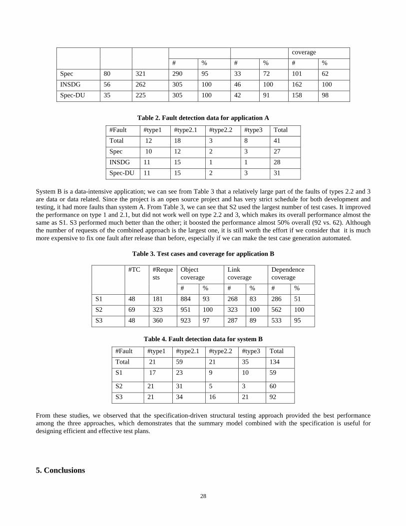
coverage # % # % # %
Spec 80 321 290 95 33 72 101 62 INSDG 56 262 305 100 46 100 162 100 Spec-DU 35 225 305 100 42 91 158 98
Table 2. Fault detection data for application A
#Fault #type1 #type2.1 #type2.2 #type3 Total Total 12 18 3 8 41 Spec 10 12 2 3 27 INSDG 11 15 1 1 28 Spec-DU 11 15 2 3 31
System B is a data-intensive application; we can see from Table 3 that a relatively large part of the faults of types 2.2 and 3 are data or data related. Since the project is an open source project and has very strict schedule for both development and testing, it had more faults than system A. From Table 3, we can see that S2 used the largest number of test cases. It improved the performance on type 1 and 2.1, but did not work well on type 2.2 and 3, which makes its overall performance almost the same as S1. S3 performed much better than the other; it boosted the performance almost 50% overall (92 vs. 62). Although the number of requests of the combined approach is the largest one, it is still worth the effort if we consider that it is much more expensive to fix one fault after release than before, especially if we can make the test case generation automated.
Table 3. Test cases and coverage for application B
Object coverage
Link coverage
Dependence coverage
#TC #Requests
# % # % # % S1 48 181 884 93 268 83 286 51 S2 69 323 951 100 323 100 562 100 S3 48 360 923 97 287 89 533 95
Table 4. Fault detection data for system B
#Fault #type1 #type2.1 #type2.2 #type3 Total Total 21 59 21 35 134 S1 17 23 9 10 59
S2 21 31 5 3 60 S3 21 34 16 21 92
From these studies, we observed that the specification-driven structural testing approach provided the best performance among the three approaches, which demonstrates that the summary model combined with the specification is useful for designing efficient and effective test plans.
5. Conclusions
28
Web applications have become more and more complex to meet the increasing demands of our daily lives. Multi-tiered architecture has become a necessary design for such systems and each tier plays an important role for each service request. Existing white-box structural testing approaches have not taken into account all the tiers in the applications, which often overlook faults caused by inter-tier dependencies. We present a modeling approach that first models each individual tier; especially, we model the presentation tier to facilitate test case generation and to reduce the complexity in testing dynamic pages. To capture inter-tier dependencies, we integrate all the tiers into an integrated dependence model and compute all the transitive closures of link and data dependencies. Finally, we reduce the integrated model into a summary model that contains inter-tier dependence information to guide effective test case generation. Our summary WGUI model contains intra- and inter-dependence relationships, which facilitates selection of fault-sensitive paths and it renders GUI presentation that reduces the complexity of testing dynamic pages and eases test case generation. The novel approach of combining the specification with the summary model enables full coverage of use cases, scenarios, and input data constraints, as well as the nodes and edges on the summary model. Our empirical studies show that this specification-driven structural testing has great potential for effective testing of web applications.
The contributions of this paper are summarized in the following:
1. We present the first model that takes all three tiers into account, and each tier is modeled in a way that can best describe their characteristics. The model not only is useful for testing, but also can facilitate impact analysis and regression testing for maintaining evolving web applications.
2. We proposed the coverage criteria for testing multi-tier web applications, which have great potential strengths for detecting faults in each tier as well as the cross-tier faults.
3. The novel approach of combining specifications and dependence models reduces the limitations of both approaches and attains the strengths of both.
In summary, the specification-driven structural testing approach along with the tool, WebMTA, developed for automatic model constructions and test case generation, can support effective testing of multi-tier web applications.
6. Acknowledgement The authors would like to thank Dr. S. S. Ravi and Dr. Seth Chaiken for their valuable suggestions, and Dr. Ye Wu for supporting the empirical study. We thank Amazon.com for allowing us to conduct the experiments on their systems. We also appreciate all the students who have been working very hard during the development of WebMTA [29].
7. References
[1] A. A. Andrews, J. Offutt, and T. Alexander, “Testing web applications by modeling with FSMs,” Software Systems and Modeling, 4(2), Springer, April 2005.
[2] M. Allen and S. Horwitz, “Slicing Java programs that throw and catch exceptions,” in Proceedings of the ACM SIGPLAN 2003 Workshop on Partial Evaluation and Semantics Based Program Manipulation, San Diego, CA, June, 2003, pp. 44-54.
[3] L. A. Clarke, A. Podgurski, D. J. Richardson, and S. J. Zeil, “A formal evaluation of data flow path selection,” IEEE Transactions on Software Engineering, 15(11), Nov. 1989, pp. 1318-1332.
[4] M. H. Chen, and M. H. Kao, “Testing object-oriented software - an integrated approach,” in Proceedings of the Tenth International Symposium on Software Reliability Engineering, Boca Raton, FL, Nov. 1999, pp. 73-83.
[5] Z. Dai and M. Chen, “Automatic test generation for multi-tier web applications,” http://www.cs.albany.edu/~mhc/WebMTA/paper3.
[6] G. DiLucca, A. Fasolono, F. Faralli, and U. Carlini, “Testing Web Applications,” in Proceedings of International Conference of Software Maintenance, Montréal, Canada, Nov. 2002, pp. 310-319.
29

[7] S. Elbaum, G. Rothermel, S. Karre, and M. Fisher II, “Leveraging user-session data to support web application testing,” IEEE Transactions on Software Engineering, 31(3), March 2005, pp. 187 - 202.
[8] P. G. Frankl, and E. J. Weyuker, “An applicable family of data flow testing criteria,” IEEE Transactions on Software Engineering, 14(10), Oct. 1988, pp. 1483 – 1498.
[9] M. J. Harrold, and M. L. Soffa, “Interprocedural data flow testing,” in Proceedings of the ACM SIGSOFT ‘89 Third Symposium on Testing, Analysis, and Verification (TAV3), Key West, FL, Dec. 1989, pp. 158-167.
[10] S. Horwitz, T. Reps, and D. Binkly, “Interprocedural slicing using dependence graphs,” ACM Transactions on Programming Languages and Systems, 1990, pp. 26 – 60.
[11] G. Kapfhammer and Mary Soffa, “A family of test adequacy criteria for database-driven applications,” in Proceedings of the 9th European Software Engineering Conference held jointly with 11th ACM SIGSOFT International Symposium on Foundations of Software Engineering, Helsinki, Finland, Sep. 2003, pp. 98 – 107.
[12] L. Larsen and M. Harrold, “Slicing object-oriented software,” in Proceedings of the 18th international conference on Software engineering, Berlin, Germany, March 25-29, 1996, pp.495-505.
[13] D. Liang and M. J. Harrold, “Slicing objects using system dependence graphs,” in Proceedings of ICSM’98, Bethesda, Maryland, November 1998, pp.358-367.
[14] C. Liu, D. Kung, P. Hsia, and C. Hsu, “Structural testing of web applications,” in Proceedings of 12th IEEE International Symposium on Software Reliability Engineering, San Jose, CA, Oct. 2000, pp. 84-96.
[15] J. Liu and M. Chen, “JATO: a Java testing and analysis tool,” http://www.cs.albany.edu/~mhc/jato. [16] A. M. Memon, M. L. Soffa, and M. E. Pollack, “Coverage criteria for GUI testing,” in Proceedings of the 8th European
Software Engineering Conference and 9th ACM International Symposium on Foundations of Software Engineering, Vienna, Austria, Sep. 2001, pp. 256-267.
[17] A. M. Memon, M. L. Soffa, and M. E. Pollack, “Hierarchical GUI test case generation using automated planning,” IEEE Transactions on Software Engineering, 27(2), February 2001, pp. 144-155.
[18] S. C. Ntafos, “A Comparison of Some Structural Testing Strategies,” IEEE Transactions on Software Engineering, 14(6), June 1988, pp. 868-874.
[19] K. J. Ottenstein and L. M. Ottenstein, “The program dependence graph in a software development environment,” In Proceedings of the first ACM SIGSOFT/SIGPLAN Software Engineering Symposium on Practical Software Development Environments, Pittsburgh, Pennsylvania, April 1984, pp. 177-184.
[20] Y. Pan, D. Pan, and M. Chen, "Slicing component-based systems,” in Proceedings of the Tenth International Conference on Engineering of Complex Computer Systems, Shanghai, China, June 2005, pp. 155 – 165.
[21] S. Rapps and E.J.Weyuker, “Selecting software test data using data flow information,” IEEE Transactions on Software Engineering, 11(4), April 1985, pp. 367-375.
[22] F. Ricca and P. Tonella, “Analysis and testing of web applications,” in Proceedings of International Conference on Software Engineering, Toronto, Ontario, Canada, May 2001, pp. 25-34.
[23] F. Ricca and P. Tonella, “Construction of the system dependence graph for web application slicing,” in Proceedings of the 2nd International Workshop of Source Code Analysis and Manipulation, Montreal, Canada, October, 2002, pp. 123-132.
[24] F. Ricca and P. Tonella, “Web applications slicing,” in Proceedings of the International Conference on Software Maintenance, Firenze, Italy, 2001, pp. 148-157.
[25] S. Sampath, Mihaylov, Souter, and Pollock, “A Scalable approach to user-session based testing of web applications through concept analysis,” in Proceedings of the 19th International Conference on Automated Software Engineering, Long Beach, CA, Nov. 2004, pp. 132-141.
[26] F. Tip, “A survey of program slicing techniques,” Journal of Programming Languages, 3(3), September 1995, pp.121-189.
[27] P. Tonella and F. Ricca, “ A 2-layer model for the white-box testing of web applications,” in Proceedings of the 6th IEEE International Workshop on Web Site Evolution, Chicago, IL, Sep. 2004, pp. 11-19.
[28] W3C Document Object Model, http://www.w3c.org/DOM. [29] WebMTA, http://www.cs.albany.edu/~mhc/WebMTA. [30] M. Weiser, “Program slicing,” IEEE Transactions on Software Engineering, SE-10(4), JUL 1984, pp. 352-357.
30