special features of the type 52 spherical annular blowout ... · spherical blowout preventer the...
TRANSCRIPT

TYPE 52SPHERICAL BLOWOUT PREVENTER
The Type 52 Spherical Annular Blowout Preventer is designed for safe well pressure control during drilling and workover operations. The short, compact design has been proven and accepted for reliable operation in all oil and gas areas in the world. Five main components: lower housing, upper housing, piston, adapter ring, and packing element allow for easy maintenance and reliability. The packing element can close on all pipe, casing, wireline, coiled tubing and other objects to its full working pressure. Stripping of pipe, tubing, and wireline through the packing element can also be accomplished at lower pressures. The 52 Blowout Preventer can also perform open hole closure per the requirements of ISO 13533 (16A). Type 52 Blowout Preventers are shorter than most annular blowout preventers and are better suited where space is a priority.
The normal configuration of the 52 Blowout Preventer is of a flanged bottom (or clamp hub) connection and a studded
top flange connection. Hydraulic operation is performed by connection to open and close (NPT) ports located on the body, which are connected to the control system. A spherical, steel reinforced rubber-packing element is forced inward by an upward movement of the piston. A spherical inverted bowl in the upper housing causes steel inserts in the packing element to rotate inward to the well bore. The steel inserts prevent extrusion of the rubber and feed inward to close on any pipe or tubular in the well bore. Replaceable bearings are used in the operating system to prevent metal contact of moving parts. An adapter ring located below the upper housing prevents contamination of the operating system during packing element replacement.
Replacement of the packing element is performed by removing nuts from stud bolting in the lower housing. The upper housing is then lifted upward. The packing element is then accessed for replacement. Wedged-cover upper housings are also available.
All materials used in the construction, except the upper housing bolting, of the Type 52 Spherical Blowout Preventer are rated by NACE MR-0175 and ISO 13533 for use in hydrogen sulfide environments.
Special featureS of the type 52 Spherical annular Blowout preventer:
n Designed and manufactured to ISO 13533 and API Specification 16A for Drill Through Equipment
n Available in all standard bore and pressure ratings
n Shorter in height than comparative annular blowout preventers
n Replaceable bearings prevent metal contact of moving parts
n Adapter ring isolates control system during packer replacement
n Special rubber materials available for non standard environments
n Standard operation pressure of 1500 psi (10,34 Mpa)
n Forged materials rated for H2S service
U P D A T E D : 1 - 2 3 - 1 1

TYPE 52SPHERICAL BLOWOUT PREVENTER
aSSeMBly Detail, type 52 (Spherical) Blowout preventerflanGe BottoM X StuDDeD top, BolteD cover
VOLUME (gal)
Size Bottom Connection A B C D E
F(lbs)
WT. (lbs)
HYD. PORTS
OPEN CLOSE
7-1/16" 3M 7-1/16" 3M 13.75 8.75 16.62 29.12 29.00 4750 2925 1” NPT 3.43 4.927-1/16” 5M 7-1/16” 5M 13.75 8.75 18.36 30.88 29.00 13000 3175 1” NPT 3.21 4.577-1/16” 10M 7-1/16” 10M 19.31 11.13 25.31 42.68 43.00 50000 10600 1-1/4” NPT 13.95 17.207-1/16” 10M 7-1/16” 15M 19.31 11.13 26.19 43.25 43.00 50000 10675 1-1/4” NPT 13.95 17.2011” 5M 11” 5M 17.69 12.62 25.56 41.50 44.75 34000 9550 1-1/4” NPT 14.60 18.7011” 5M 11” 10M 17.69 12.62 26.68 42.62 44.75 34000 9800 1-1/4” NPT 14.60 18.7013-5/8” 3M 13-5/8” 3M 19.68 10.88 22.56 40.74 46.38 34000 9100 1-1/2” NPT 14.67 23.5013-5/8” 5M LW 13-5/8” 5M 19.56 12.38 24.25 42.25 46.50 50000 10000 1-1/2” NPT 14.67 23.5013-5/8” 5M 13-5/8” 5M 20.67 12.00 26.31 44.98 50.00 50000 13650 1-1/2” NPT 17.41 23.5813-5/8” 5M 13-5/8” 10M 20.62 12.00 30.38 49.12 50.00 50000 14200 1-1/2” NPT 17.41 23.5820-3/4” 3M 20-3/4” 3M 21.41 14.16 38.31 48.44 54.12 50000 14600 1-1/2” NPT 26.90 43.4021-1/4” 2M 21-1/4” 2M 21.06 8.00 28.12 46.25 49.00 50000 10850 1-1/2” NPT 16.92 32.59
Notes:1. Upper body lift eyes, 2 places at 180°. Lift capacity “F” per lift eye.
TYPE 52SPHERICAL BLOWOUT PREVENTER
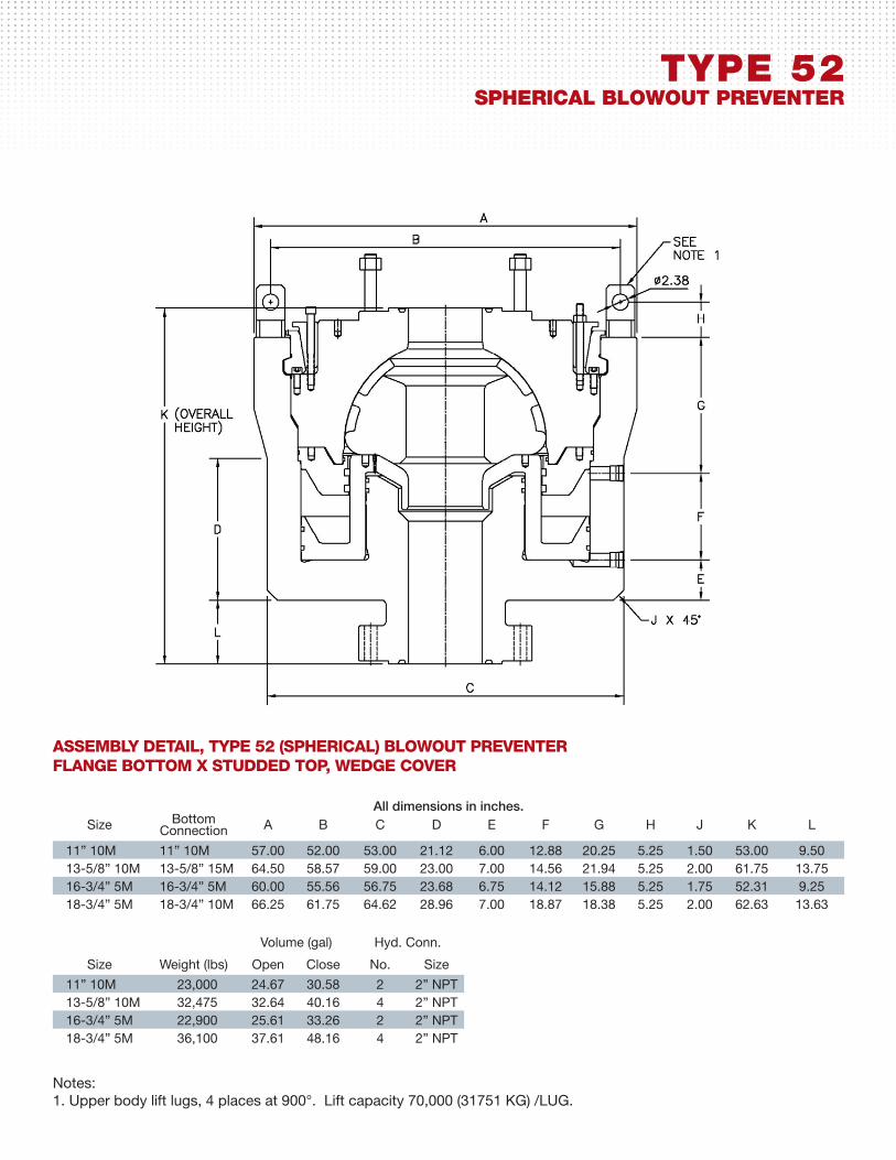
aSSeMBly Detail, type 52 (Spherical) Blowout preventerflanGe BottoM X StuDDeD top, weDGe cover
Size Bottom Connection A B C D E F G H J K L
11” 10M 11” 10M 57.00 52.00 53.00 21.12 6.00 12.88 20.25 5.25 1.50 53.00 9.5013-5/8” 10M 13-5/8” 15M 64.50 58.57 59.00 23.00 7.00 14.56 21.94 5.25 2.00 61.75 13.7516-3/4” 5M 16-3/4” 5M 60.00 55.56 56.75 23.68 6.75 14.12 15.88 5.25 1.75 52.31 9.2518-3/4” 5M 18-3/4” 10M 66.25 61.75 64.62 28.96 7.00 18.87 18.38 5.25 2.00 62.63 13.63
Volume (gal) Hyd. Conn.
Size Weight (lbs) Open Close No. Size
11” 10M 23,000 24.67 30.58 2 2” NPT13-5/8” 10M 32,475 32.64 40.16 4 2” NPT16-3/4” 5M 22,900 25.61 33.26 2 2” NPT18-3/4” 5M 36,100 37.61 48.16 4 2” NPT
All dimensions in inches.
Notes:1. Upper body lift lugs, 4 places at 900°. Lift capacity 70,000 (31751 KG) /LUG.