space launching site protection against lightning hazards
TRANSCRIPT
HAL Id: hal-01184421https://hal.archives-ouvertes.fr/hal-01184421
Submitted on 14 Aug 2015
HAL is a multi-disciplinary open accessarchive for the deposit and dissemination of sci-entific research documents, whether they are pub-lished or not. The documents may come fromteaching and research institutions in France orabroad, or from public or private research centers.
L’archive ouverte pluridisciplinaire HAL, estdestinée au dépôt et à la diffusion de documentsscientifiques de niveau recherche, publiés ou non,émanant des établissements d’enseignement et derecherche français ou étrangers, des laboratoirespublics ou privés.
Space Launching Site Protection against LightningHazards
F. Issac, E. Bachelier, D. Prost, V. Enjalbert, L. Mohedano
To cite this version:F. Issac, E. Bachelier, D. Prost, V. Enjalbert, L. Mohedano. Space Launching Site Protection againstLightning Hazards. Aerospace Lab, Alain Appriou, 2012, p. 1-20. hal-01184421

Issue 5 - December 2012 - Space Launching Site Protection against Lightning Hazards AL05-12 1
Lightning Hazards to Aircraft and Launchers
Space Launching Site Protection against Lightning Hazards
F. Issac, E. Bachelier, D. Prost (Onera)V. Enjalbert(DGA)L. Mohedano (APAVE)
E-mail: [email protected]
A launching pad, because of its activity, is par ticularly sensitive to the risk of lightning. The use of Standard IEC62305 "Protection
against lightning" establishes the general framework for the Lightning Protection System (LPS). However, the specific activity of a launching pad requires special analysis on specific points of the LPS. Indeed, it is necessary to take into account the lightning conductor system par ticularity on the one hand, and the launcher electromagnetic susceptibility on the other hand. This paper presents the general methodology used to define the LPS of a launching pad. The analysis is based upon exper tise, numerical simulation and experiments performed at launching pad sites.
Introduction
A rocket launching pad is, by its very nature, a zone particularly sensitive to the risk of lightning. Generally located in parts of the earth globe where lightning activity is strong, launching installations are in addition being built in obstacle-free zones measuring a few square kilometers and comprise tall structures; all of these elements unfortunately favor lightning attraction.
While the metallic structures of the launcher building complex can be used as a lightning conductor and can thus drain the lightning current in a natural way, in many cases they present the major disadvantage of being lower than the launchers that they could protect.
This is why a launcher lightning protection must be built in a specific way; the protection depends on both the launcher and on the way it is operated in its various configurations before launching.
Various lightning protection solutions can be used according to the type of launcher and its management. Protection solutions based on gantries can be used and various types of lightning rods with their specific down-conductors (draining current solution) can be implemented.
Even though there is no record of serious incidents on CSG (Centre Spatial Guyannais, the Guyana Space Center) launching sites, its lightning protection system has changed over the past thirty years because the obligations to take lightning risk into account have become increasingly constraining.
Consequently, the launcher protection solutions follow the changes in the international standardization and lightning risk management.
For this particular activity, though, the application of standards is not sufficient to guarantee the absence of any lightning risk. Nevertheless, standards define a minimum applicable framework for the design of the protection.
The objective of this article is, first, to briefly present the phenomenology of a lightning aggression on buildings and the specificity of a launching site subject to such an aggression. Then, the safety of the installation and evaluation of the lightning protection devices are discussed.
Lightning protection of a launcher
On November 14th, 1969, 36.5 seconds after lift-off, Apollo XII triggered a lightning discharge, followed by another stroke a few seconds later. This event is the most famous lightning strike of a rocket; by chance, it did not have serious consequences on the mission. Although the ground installations of the launching pad in Florida, with a high keronic level, had lightning protection, the risk after lift-off had clearly been underestimated. The knowledge of the attachment mechanisms in the first seconds of flight, the impact of the ionized exhaust plume on the electric field and the capacity of the rocket to trigger the lightning discharge had been very widely underestimated. This incident imposed a modification of lightning risk management after lift-off.

Issue 5 - December 2012 - Space Launching Site Protection against Lightning Hazards AL05-12 2
However, the modification of the lightning risk management rules did not prevent the loss of the Atlas Centaur rocket on March 27th, 1987, struck in flight, which led to the destruction of the rocket. This accident definitively showed that the risk of lightning is an important problem in all phases of the life cycle of a rocket.
In the rocket assembly phases, the risk of a direct lightning strike is lower because the launcher is protected inside buildings with metal framework structures, offering significant protection. However, this risk must not be underestimated because of a pyrotechnic issue, which concerns all of the Electro Explosive Devices (EED) of the rocket and also all of the electronic control devices. All the same, in these assembly phases, the analysis that must be carried out remains an indirect lightning analysis.
In the transfer phases of the rocket, when part of the rocket or the whole rocket is outside the building complex, direct lightning becomes a main risk. In such a configuration, the rocket cannot be protected by a system like a lightning conductor system and its protection can only be guaranteed by proper weather forecasting.
The difficulty lies in obtaining a reliable forecast over a period of a few hours, with weather configurations that can change very fast.
If we take the example of the CSG launching pads, the lightning forecast is based on weather radar giving the evolution of storm cells, but also on more specific devices giving information on the electric activity of these cells, namely:
• a network of field mills "MAC" ( “Moulin À Champ” in French) giving the intensity of the electric field on the ground in real-time;
• the "THOR" (Thunderstorm Occurrence) system based on radio-electric interferometry techniques and giving information on the electrical activity within storm cells. This system makes it possible to follow the movement of the electric activity and makes it possible to differentiate cloud-to-cloud discharges from cloud-to-ground discharges.
In the phase before lift-off, the rocket is parked on the launching pad for several days and protection cannot be ensured by weather forecast alone. Protection is thus ensured by lightning conductors and possibly by a mobile gantry. This phase is particularly critical, on the one hand because the probability of lightning is strong due to the size of the installations and, on the other hand, because of the launcher state with all pyrotechnic systems, the loading of propellants, the control systems and the payload. In this configuration, the launcher must be protected from any direct lightning strike, but also from all significant electromagnetic coupling phenomena.
Finally, the launcher lift-off phase is rather similar to the transfer phases, since the launcher cannot be protected by an additional system. Only the weather forecasts can predict the lightning risk and thus give the authorization for rocket launch. Nevertheless, the problem here is a little different from that in a transfer phase, in the sense that only a short temporal window is required for the weather forecast.
Lightning in a few words
Lightning is a complex natural phenomenon. Before looking at the lighting protection system (LPS) of a rocket, we will recall some characteristics of the physics of lightning and of the reasoning behind the protection. It is important to note that there are many
physical mechanisms related to lightning and that, in the present state of the knowledge, the physics of these has been rather well mastered. Laboratory experimentation on long gap discharges and experimentation on natural lightning have contributed to making important progress on this issue. However, in spite of the present scientific understanding of these physical mechanisms one is still not able to predict the point of the lightning impact with good accuracy. This is why, for two hundred years, the best protection for installations is still Franklin’s rod.
Lightning features
As seen in [1], the initial process leading to lightning takes place within a thunderstorm cloud, with the creation of electric charges. The electrification phenomena within the cloud generate sufficiently high electric fields to induce electrical discharges inside the cloud (cloud-to-cloud, CC discharge) or between the cloud and the ground (CG discharge). It is this last type of discharge that is of interest to us. It generally consists of the joining of two (not simultaneously emerging) propagating leaders one downward from the cloud to the ground and one upward from the ground to the cloud. Because of the two possible polarities of electrically charged particles and the two different time orderings of the formation of the leaders, we have four different types of connections between the cloud and the ground [2] [3].
Figure 1 presents the four configurations of CG lightning. The classification is first based on the behavior of the initial leader (downward or upward) and then based on the sign of the current flow of the first return stroke (when the connection of the two leaders is made).
Negative discharge Positive discharge
Downward leader
+++
+++ ++
++++
+ + + + +
++++
−−−−−−−−
I
−−
−−−
−−
−
−−
−−
++ + +
++ +
+++
+ +
++
+
++
+ +
++
+
−−−−−−−−
I
−−
−−−
− − − − −
Upward leader
++
+++++
++
+
+ +
++
++
+ + +
+++
−−−−
−−−
−
I
− −−−−−−−
−− −
−
++
+
+++ +
++
+
++ +++
+ +
+
++ +
− −−−
− −− −
I
−−
−
− −
−−−
−
− − −Figure 1 – CG discharge classification
In agreement with the ordering of the figures in figure 1, the most frequent discharge is the negative discharge with an initial downward leader. The propagation of the leader does not follow a simple curve, it has many separate branches. In this case, the connection point with the ground depends on local electrical conditions in the neighborhood of the nearest
Issue 5 - December 2012 - Space Launching Site Protection against Lightning Hazards AL05-12 3
branch to the ground. We will see in the following sections, that these local conditions are the basis of the models used in lightning protection for buildings.
A second type of discharge is induced by an initial upward propagating leader. In this case, the electric field intensification at the top of a structure is strong enough over a large area to initiate the propagation of the leader. In this configuration, the connection point is directly linked with the structure. This scenario is typically obtained on structures that are over 100 m high [3]. We will keep in memory that this height of 100 m is of the order of the height of the lightning protection systems of the Guyana Space Center launching pads and this point will be later used in our discussion.
The striking distance and the electro-geometric model
In the most frequent case of lightning, i.e., for a downward negative discharge, the advance of the negative leader by jumps intensifies the electric field between the head of the leader and the ground. When the negative leader approaches the ground, this field is sufficiently intense to initiate an ascending discharge from the ground. The distance in this last phase before the connection of the two leaders is called the “striking distance”. This attraction distance depends on the area in which the electric field exceeds an electric breakdown value. The intensity of this value is thus quite large (about 500 kV/m [4]). The electric charge carried by the negative leader makes it possible to calculate the electric field between the head of the leader and the ground, but also the intensity of the first return stroke. From this consideration, there is a relation between the current of the return stroke and the striking distance. During the seventies [3][5], models based on experimental results made it possible to establish the following relation between the current intensity and the striking distance (1).
0.6510.r I= (1)
Where r is the striking distance and I is the current of the return stroke in kA.
In agreement with the recommendations of various standardization committees [6], this relation is used as a basis for dimensioning the lightning protection system.
The rolling sphere method
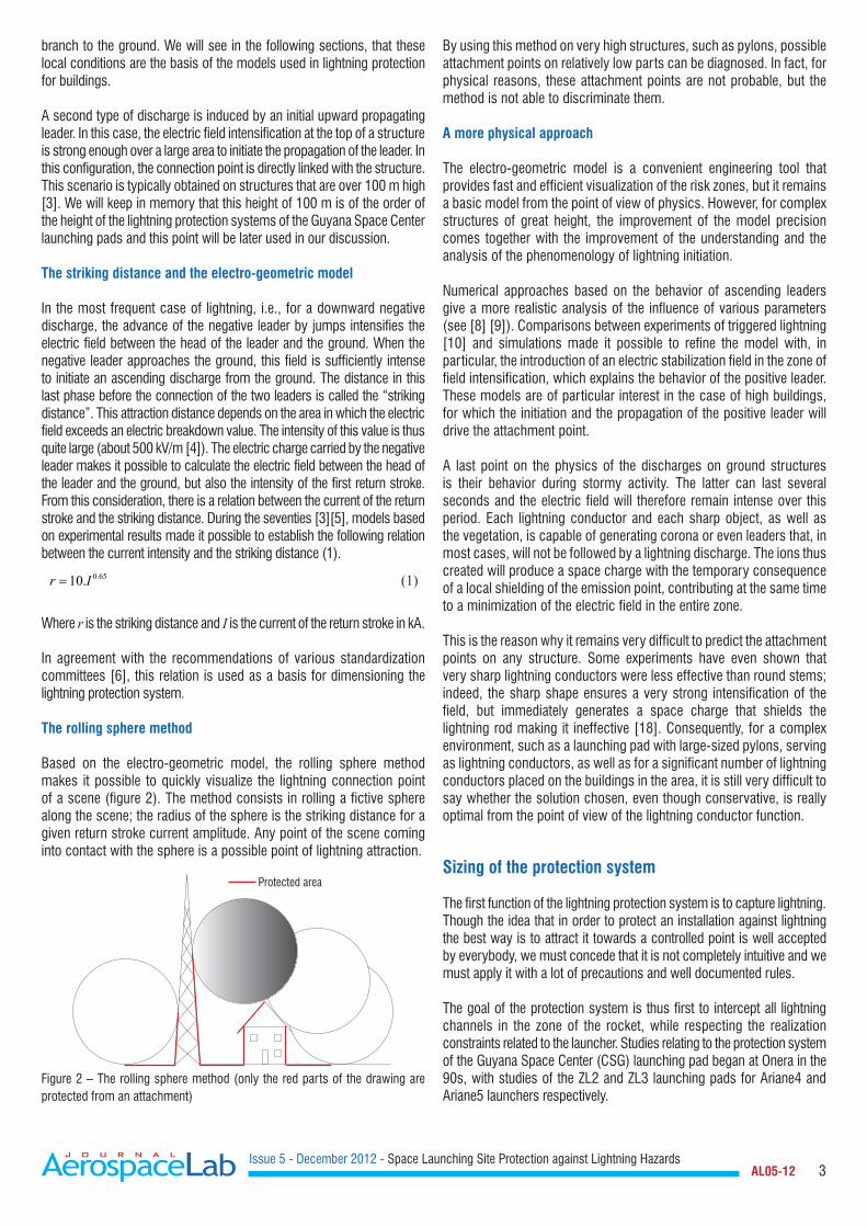
Based on the electro-geometric model, the rolling sphere method makes it possible to quickly visualize the lightning connection point of a scene (figure 2). The method consists in rolling a fictive sphere along the scene; the radius of the sphere is the striking distance for a given return stroke current amplitude. Any point of the scene coming into contact with the sphere is a possible point of lightning attraction.
Protected area
Figure 2 – The rolling sphere method (only the red parts of the drawing are protected from an attachment)
By using this method on very high structures, such as pylons, possible attachment points on relatively low parts can be diagnosed. In fact, for physical reasons, these attachment points are not probable, but the method is not able to discriminate them.
A more physical approach
The electro-geometric model is a convenient engineering tool that provides fast and efficient visualization of the risk zones, but it remains a basic model from the point of view of physics. However, for complex structures of great height, the improvement of the model precision comes together with the improvement of the understanding and the analysis of the phenomenology of lightning initiation.
Numerical approaches based on the behavior of ascending leaders give a more realistic analysis of the influence of various parameters (see [8] [9]). Comparisons between experiments of triggered lightning [10] and simulations made it possible to refine the model with, in particular, the introduction of an electric stabilization field in the zone of field intensification, which explains the behavior of the positive leader. These models are of particular interest in the case of high buildings, for which the initiation and the propagation of the positive leader will drive the attachment point.
A last point on the physics of the discharges on ground structures is their behavior during stormy activity. The latter can last several seconds and the electric field will therefore remain intense over this period. Each lightning conductor and each sharp object, as well as the vegetation, is capable of generating corona or even leaders that, in most cases, will not be followed by a lightning discharge. The ions thus created will produce a space charge with the temporary consequence of a local shielding of the emission point, contributing at the same time to a minimization of the electric field in the entire zone.
This is the reason why it remains very difficult to predict the attachment points on any structure. Some experiments have even shown that very sharp lightning conductors were less effective than round stems; indeed, the sharp shape ensures a very strong intensification of the field, but immediately generates a space charge that shields the lightning rod making it ineffective [18]. Consequently, for a complex environment, such as a launching pad with large-sized pylons, serving as lightning conductors, as well as for a significant number of lightning conductors placed on the buildings in the area, it is still very difficult to say whether the solution chosen, even though conservative, is really optimal from the point of view of the lightning conductor function.
Sizing of the protection system
The first function of the lightning protection system is to capture lightning. Though the idea that in order to protect an installation against lightning the best way is to attract it towards a controlled point is well accepted by everybody, we must concede that it is not completely intuitive and we must apply it with a lot of precautions and well documented rules.
The goal of the protection system is thus first to intercept all lightning channels in the zone of the rocket, while respecting the realization constraints related to the launcher. Studies relating to the protection system of the Guyana Space Center (CSG) launching pad began at Onera in the 90s, with studies of the ZL2 and ZL3 launching pads for Ariane4 and Ariane5 launchers respectively.

Issue 5 - December 2012 - Space Launching Site Protection against Lightning Hazards AL05-12 4
In regard to the protection of the Soyuz launching pad (ZLS), the reasoning behind the protection applied by Onera has been very similar. However, the installation constraints had changed significantly.
As we saw, the electro-geometric model is the starting point for sizing the lightning protection system, because the simulation tools for calculating the attachment points of the lightning are not mature enough to be accepted by the regulatory authorities.
The electro-geometric model is therefore applied in the design of the system, with the objective of never having lightning on the rocket. However, this objective is difficult to achieve. One of the main difficulties is the requirement to leave a free opening for the launching of the rocket.
The second function of the LPS is related to the susceptibility of the launcher due to induced EM effects generated by the currents flowing within the protection system. The objective is therefore to maintain the magnetic field within the launcher zone below an acceptable level, depending on the susceptibility of the launcher to this magnetic field.
Consequently, the most efficient protection system would be a Faraday cage. However, the problem is that such a perfect situation is not possible, because there must be an opening in order to let the launcher penetrate the LPS during its installation phase and to let it out from the top during the taking-off phase.
Protection system analysis on a model structure
To understand the mechanisms of attachment on the LPS of the ZL3 launching pad at the Guyana Space Center (CSG), experiments were carried out in France in the 90s at the Renardières (EDF) research center on a 1/20 scale model structure of the launching pad (figure 3).
Figure 3 – Scale model of the Ariane 5 Launching pad
It was possible to generate long electric discharges with positive and negative polarities at the Renardières site. From the phenomenological point of view, these simulated discharges are very close to natural discharges. This experimental test allowed the estimation of the effectiveness of the protection system and its capacity to protect
the launcher. Several measurements were made with two or four protection pylons and with different offsets between the axis of the model and the axis of the top electrode in a "needle-top-electrode/ ground-plane" type arc configuration (figure 4).
Figure 4 – Long electric discharges generated on the ZL3 mockup (launcher and protection system)
Under the laboratory conditions, the system was never put at fault (no discharge reached the launcher), but the main question was to know whether a scaling law was applicable. In particular, it is known that in the laboratory there is no direct relationship between the attachment distance and the current of the discharge; the latter being, in this case, a function of the voltage and of the internal impedance of the generator.
Later work [12] showed that, in the tested laboratory configurations, the relevant parameter is the difference of height between the pylons and the launcher. In order to test the influence of this parameter, ellipsoids with various heights have been simultaneously subjected to the same type of long electric discharge. For this, the former needle high voltage electrode was replaced by a flat metal plate, of large dimension, creating a homogeneous electric field zone at ground level (figure 5).
R2R1Electrodes
(15 x 18 m)
U(t)
7.04
m
h2h1
Figure 5 – Tests on ellipsoids with large plate top electrode

Issue 5 - December 2012 - Space Launching Site Protection against Lightning Hazards AL05-12 5
For ellipsoids at equal heights, their eccentricity (and therefore, their sharpness) influences the electric-breakdown statistics. However, the difference of height between the electrodes very quickly becomes the relevant parameter for ellipsoids of different heights. The explanation must be sought in the behavior of the positive discharge. A streak image of an upward positive leader measured between the two electrodes (the top plate and the ellipsoid on the ground) provides an idea of the connection between the two objects (figure 6). It is difficult to identify the start of the leader with the streak image, because of the mixing of time and space. Perhaps the ellipse with the most pointed profile starts first but, even with this hypothesis, there is a faster connection for the larger ellipse.
1 2
Figure 6 – Streak image of an upward positive leader at the top of the two ellipsoids
As a conclusion, the laboratory experiments do not make it possible to give the actual effectiveness of the lightning protection system. However, they contribute two important items of information:
a) The presence of two leaders on two separate objects of different height is possible. This behavior will exist for natural lightning. As far as the LPS protection is concerned, the question that arises is thus to evaluate the capacity of a leader to propagate from the top of the rocket placed inside the protection system. This specific point cannot be covered by normalization rules.
b) The laboratory discharges allowed realistic attachment models to be obtained. These models were used to analyze the leader starting configurations and can be used as a basis to answer the previous problems [11] [12].
Lightning protection system design
It is difficult to define and optimize a launcher lightning protection system using laboratory experiments and the knowledge of lightning attachment mechanisms on tall structures. This is why the design of the lightning protection system is done almost exclusively using the electro-geometric model, as defined in the international standard procedures. However, these standardized approaches cannot guarantee a total reliability of the launching pad lightning protection system.
Therefore, in order to comply with the electro-geometric model and to intercept most of the lightning strike, it is necessary to place lightning conductors in the launcher zone. With respect to the CEI 62305 standard [6], the most constraining protection level is "LPL I" 3 kA, which gives a radius of 20 m for the rolling sphere.
The installation of pylons is costly and must be taken into consideration. The smaller the number of pylons, the lower the LPS budget will be.
Several solutions are possible considering these constraints.
Umbrella
This is a system with conducting wires linked onto a single dielectric support, placed at the top of the gantry. It was the principle of the protection system used on the shuttle launching pad at the Kennedy Space Center. With such a protection system, with four electric cables descending to the ground, the electro-geometric model reveals a good protection for the high parts of the launcher. However, the application of the electro-geometric model reveals a protection default for the lower parts (figure 7). For example, if we want to protect this 50 m-high rocket with a 90m-high mast and four wires placed at 45 °, the electro-geometric model shows that the structure is not protected for lightning currents of 3 kA (radius of the sphere = 20 m); this structure is protected for 5 kA currents only (sphere of radius=30 m).
50 m
Figure 7 – Application of the electro-geometric model to an umbrella LPS
Figure 8 shows the unprotected area of the structure for a protection level “I”. Obviously, the lower part of the structure is not a lightning attachment zone for physical reasons, as we have mentioned previously; however, this solution will be eliminated, because it does not comply with the electro-geometric model. In addition, we will see hereafter (next section) that other more physics-related reasons will eliminate this solution. However, this shows one of the limitations of the model used in the standard for the umbrella type of protection system.
r=20 m
m
1008060402000
20
40
60
80
100
Protected structure
Unprotected area
r=30 m
m
1008060402000
20
40
60
80
100
Protected structure
Area protected by the ground
Area protected by the wires
Figure 8 – Limits of the protected area
Association of lightning conductors
To protect the launcher efficiently, the simplest solution is to place several metallic pylons at a distance lower than 20 m. Solutions with three or four sufficiently high pylons both guarantee lightning

Issue 5 - December 2012 - Space Launching Site Protection against Lightning Hazards AL05-12 6
interception and comply with the electro-geometric model for lightning strokes of intensity higher than 3 kA. Under these conditions, it is rather easy to perform the lightning conductor function.
Electromagnetic sizing of the protection system
We have seen that rocket protection against direct lightning is rather easy to achieve by positioning three or four pylons of great height around the rocket. The difficulty that arises now is the susceptibility of the launcher and the critical electronic equipment to the magnetic field induced by the lightning current in the protection pylons. A launcher such as ARIANE 5 is hardened against a direct lightning strike of 5 kA, with a 4 μs rise time and a 500 μs decay time [13][14].
By the way, the hardening of the rocket on the launching pad must be evaluated with its umbilical connections, which means with all of its connections to the nearby infrastructure (in particular, the tower).
Applying Ampere’s law, a 5 kA current on the rocket generates a magnetic field of around 200 A/m. Although the aggression of an indirect lightning strike does not expose the launcher to the same constraints as a direct effect, we will consider that the magnetic field produced by the lightning on the pylons should not itself exceed the value of 200 A/m in the launcher area.
This hypothesis makes it possible to simplify the study of the rocket susceptibility on the launch pad, by concentrating on the maximum field constraint to which it can be exposed.
If we choose the solution consisting of a protection system with four independent lightning conductors, installed on the four corners of a square base with 40 meter edges, a lightning current of 200 kA could appear in any pylon individually and generate a magnetic field greater than about 2 kA/m in the launcher zone. This value is not acceptable in view of the rocket susceptibility. It is thus necessary to modify the system in order to minimize this constraint.
We have seen that the solution for the LPS is to guarantee a situation as close as possible to a Faraday cage. However, it must remain at least open on one side and on the top for the regular installation and take-off phases of the rocket respectively. In the following, several solutions are proposed.
Separation function
The goal of the separation function is to reject the lightning current to the earth, as far away as possible from the launching zone. The ideal protection system is to use four pylons (for the lightning conductor function described above), each of these supporting catenary wires with insulators. The catenary wires themselves interconnect four lightning rods placed on the insulators to a faraway independent earth-termination system.
The insulator must prevent an electric discharge between the wires and the top of the pylons. This is the system that is currently in operation on the Ariane5 ZL3 launching pad.
Insulator
A/m180001600014000120001000080006000400020000
a) Transverse magnetic field plane-section at the level of the insulators
A/m180160140120100806040200
b) Transverse magnetic field plane-section at the level of 40 mFigure 9 – Maximal magnetic field in the launcher area
This solution has the advantage of minimizing the magnetic field in the launcher area. In a nominal operating mode of this protection, it is rather easy to maintain low intensities of the magnetic field and for it to be compatible with the susceptibility of the launcher (figure 9).
However, this solution presents two disadvantages that should not be underestimated if we want to maintain the effectiveness of the lightning protection system during its entire operational life. Let us consider the example of the ZL3 again for our purpose.
The first problem concerns remote connection exiting the launching area. For example, the LOX tanks and the water tower; between these two zones and the launcher pad there are large metallic pipes. These pipes are very close to the LPS grounding system (figure 10). The potential rise going together with the lightning current in the ground can induce a current in the pipelines; this current can, firstly, modify the magnetic field on the launching pad, but it can also affect the safety of the LOX tanks.

Issue 5 - December 2012 - Space Launching Site Protection against Lightning Hazards AL05-12 7
LPS
Lox pipe
Critical point
Figure 10 – Seen from above the ZL3 launch pad
The second problem is related to the maintenance of the insulators at the tops of the pylons. The efficiency of the separation function is based on the insulation capacity of the isolators. The problem is the degradation of the dielectric rigidity, on the one hand due to ageing and on the other hand because of surface pollution of the isolators. A strong lightning strike may therefore produce a breakdown of these insulators if they are not as perfect as expected; under these conditions, the pylon will become a shunt for the current due to its impedance being lower than that of the wires. A significant part of the injected current is thereby conducted to the normally protected zone!
Mesh cage
Given the cost related to the maintenance of a protection system based on the separation function, an alternative solution is to use the pylons as down-conductors for the lightning current. By connecting the top of the pylons with electric cables, we build a large-sized meshed system, close to a simplified Faraday cage. The minimization of the magnetic field in the launcher area is obtained by the current distribution through the four pylons and by the geometrical effect (i.e., the canceling of the field between two conductors carrying equal currents) this guarantees a shielding effectiveness at the center of the system. The better the balance of the currents is, the better the shielding performance of the system. Figure 11 presents the ideal solution for the magnetic field of four pylons built on a square base with 60 m edges. This figure shows that the value of the magnetic field at the center of the zone is much lower than 200 A/m; this solution is thus possible from the point of view of the electro-geometric model, as well as from the point of view of the maximum acceptable magnetic field. Because only based on geometrical symmetry properties, this solution is independent of the current strike frequency spectrum.
A/m720640560480400320240160800
Figure 11 – Magnetic field for a perfect current balance on four pylons built on a square base with 60 m edges
In reality, the lightning connection point breaks the symmetry of the system; it is thus necessary, before making the choice of the final LPS design, to evaluate the parameter that most influences the current distribution.
With simple simulation models, it is possible to estimate the effect of the various resistances and inductances of the system on the solution. In a simple way, the LPS can be represented by figure 12 with three groups of impedances, which are the impedances of the connection cables (Zwire), the impedance of the pylons (Zpylon) and the impedance of the grounding system of these pylons (Zground).
Zwire
90 m
Zpylon
Zground
B
A D
C
Figure 12 – Equivalent circuit of the pylons and the injection current
Taking into account the impedances of the various conductors and the point of impact of the lightning, the solution is now dependent on the spectrum of the aggression.
For a simple geometrical configuration (figure 12) and by using an electrical circuit-based simulation tool like a PEEC tool, it is easy to estimate the weight of the various impedances in the balance of the currents in the system. However, to simplify the numerical model, the current waveform used to simulate the lightning is this wave A of Standard ED84, namely:
( )0( ) t ti t I e eα β− −= −
where α and β are the coefficients given in table 1.
I0 218810 A
α 11354 s-1
β 647265 s-1
Table 1 – Coefficients for the waveform A
With a nonsymmetrical lightning current injection, the connection wires between the pylons have significant influence. With a low impedance value of these connections we can expect a balance distribution of the current in the four pylons. The impedance of this connection is controlled by the inductance of the wire and this inductance is higher than the pylon inductance. These connections will strongly influence the current distribution. A significant improvement of the impedance can be obtained by increasing the number of conductors between each pylon. Indeed, with several separate parallel cables we create an equivalent conductor, with a characteristic dimension much greater than the radius of the elementary wire and thus with a lower inductance.

Issue 5 - December 2012 - Space Launching Site Protection against Lightning Hazards AL05-12 8
Table 2 gives the distribution of the current in the four pylons for two configurations:
• a single connection cable between two pylons;• four wires with 1m separation between two pylons.
With four wires, the reduction of the impedance allows a better balance of the current in the four pylons and of course a minimization of the magnetic field in the launcher zone. The result approaches the optimal solution of the perfect equal current distribution.
Pylon A Pylon B Pylon C Pylon D Std
1 cable 26053 37907 98599 37907 32801
4 cables 34496 43324 79232 43324 19866
Table 2 – Maximal currents in Amps for a 200 kA injected current
The results in figure 13 show the improvement of the magnetic field due to the use of multiple parallel cables between the pylons.
A/m720640560480400320240160800
a) b)Figure 13 – Magnetic field in the launcher area for the two configurations (a) single cable between the pylons (b) four wires, between the pylons, separated by 1m
The second element that may have a theoretical impact on the current distribution is the resistance of the pylon grounding system. However, for an aggression of waveform A (200 kA) on a given pylon, table 3 shows that the resistance value of the ground electrodes must be relatively high to obtain a well-balanced current distribution. However, a high value of the ground resistance would not be desirable for a lot of other reasons. Especially, they would not guarantee the draining of high current flows into the ground as expected of such grounding systems.
Rground (Ω) Pylon 1 Pylon 2 Pylon 3 Pylon 4 Std
1 33660 43205 79489 43205 20239
10 43690 47435 66030 47435 10077
20 46783 48800 60922 48800 6467
50 49184 49714 53348 49714 1921
Table 3 – Current distribution over the pylons for various values of the resistance of the ground electrode (Rground) and standard deviation (Std) of the current for each Rground configuration
Consequently, it is out of question to think of deteriorating the quality of the ground electrodes in order to improve the current balance in the pylons; the grounding system resistances cannot be an adjustable parameter to control this current distribution.
Optimization of the mesh cage
The main difficulty with this solution is the balance between the minimization of the magnetic field and the penetration of the rolling sphere.
Indeed, from the point of view of the electro-geometric model, it is necessary to bring the pylons as close as possible, but in this case we increase the residual intensity of the magnetic field induced by the lightning impact on the LPS at the level of the rocket area. A compromise must thus be sought between the maximum intensity of an acceptable strike on the launcher and an acceptable electromagnetic environment due to a strike on the LPS. To have a protection of level I according to the IEC62305 standard, the protection for a current intensity higher than 3 kA leads to a rolling sphere radius equal to 20 m. To obtain this protection, the maximum distance between the pylons must be of 40 m.
A simplified simulation of the two solutions, with 40 m or 60 m separation between the pylons, corresponding to a rolling sphere of 20 m or 30 m respectively, shows that the solution with closer pylons (20 m) cannot ensure a sufficiently low level of the magnetic field (figure 14). Moreover, one solution with pylons on a square base with sides measuring 40 m also has strong constraints, such as the proximity to the rocket during the launch.a)
A/m9000800070006000500040003000200010000
A/m720640560480400320240160800
b)
720640560480400320240160800
A/m
A/m9000800070006000500040003000200010000
Figure 14 – Maximum magnetic field within the LPS (a) distance between pylon 40 m (b) distance between pylon 60 m
The lightning protection system is finally made of four 90 m-high pylons on a square base with sides measuring 60 m. The pylons will be connected by their tops with a set of four parallel wires.
Evaluation of the solution selected
Three main criteria have been retained for the design and the realization of the lightning protection system of the Soyuz launching pad (ZLS) in Guyana. Those are:
• the system effectiveness, namely the launcher must be protected from any lightning strike of intensity higher than 5 KA;
• the cost of the system;• the maintenance of the system.
The effect of the last two criteria was to favor a mesh cage solution, with the use of pylons as down-conductors for the lightning current.

Issue 5 - December 2012 - Space Launching Site Protection against Lightning Hazards AL05-12 9
The preliminary study made it possible to define the broad lines of the LPS design, pointing out the important role played by the cables between the tops of the pylons in the system effectiveness.
For a current of 5 kA and a 30 m rolling sphere, the standard gives a Type II protection level, but this solution was found as the best compromise between a direct lightning strike of 5 kA on the rocket and a high level lightning strike of 200 kA on the LPS.
Figure 15 – Rolling sphere on the LPS of Soyuz launching pad in Guyana
Then, the adopted solution must be analyzed with the particular operating constraints of the Soyuz launching pad; for example with a gas pipe of a very large dimension (figure 16). On the one hand, this zone does not allow the location of the pylons in a perfectly symmetrical configuration and we must recall the influence of the system inductances on the balance of the currents. On the other hand, the latter analysis is unable to take into account the impedance of the grounding network; it has only shown that the ground resistance could not be a driving parameter. However, the ground network cannot be comparable to a simple local resistance on each pylon. It is thus necessary to study the global behavior of the site upon receiving a lightning strike, by taking into account the actual geometry and the ground parameters.
Impedance of the grounding network and pylons grounding
It is widely known that the grounding system is a critical point of the lightning protection system. Indeed, if one wishes to minimize the overvoltage induced by the lightning current, the ground connection must have low impedance. The element that will condition the grounding value is the ground in contact with the ground electrode and of course, the conductivity of the ground is not an easily modifiable parameter. This will impose a dimension of the ground electrode according to the conductivity of the ground, with the disadvantage of increasing the impedance with the size of the buried system for low conductivity ground.
In the case of the Soyuz lightning protection system, we have evaluated the impact of the grounding of the pylons. The problem here is very specific, but it makes possible an evaluation, in a concrete grounding configuration, of different grounding system solutions.
For mechanical reasons, the Soyuz launching pad is built on a rock zone. The ground topology and the final installation of the site result in
the fact that each pylon cannot be put to ground identically. Figure 16 presents a cross-section of the ground, with the two different added dirt and rock ground layers, respectively of resistivity of 30 Ωm and 300 Ωm.
Added ground
Rock
Figure 16 – Cross section geometry of the pylon installation on the Soyuz LPS and picture of the flue (flame exhaust)
From a general point of view; the launching pad ground consists of two different layers. The deepest layer has a resistivity of 300 Ωm; a more conductive ground of 30 Ωm was brought back onto this layer. The grounding of the pylons in the flue (flame exhaust) is thus more difficult to perform and is the cause of local ground electrodes of lower quality. However, since all of the grounding systems are interconnected, the value of the ground resistance of the entire site is very low. Therefore, for the low frequency components of the current spectrum the behavior of the grounding will be good; however, for the high frequency components, the inductance of the ground electrodes will deteriorate the performance of the grounding.
However, by using the impedance parameter, it is difficult to quantify the quality of the site. Indeed, this impedance is frequency dependent because of an inductive behavior.
In order to evaluate the behavior of a ground electrode subjected to a lightning excitation and to evaluate the impact of its inductive part, we will first analyze the overvoltage V related to the current flow in the grounding system. In a very simplified way, the latter can be written as follow:
dIV RI Ldt
= + (2)
and in the frequency domain:
( )V RI jL I V R jL Iω ω= + = = + (3)
The ground makes this simple problem complicated, because the real part

Issue 5 - December 2012 - Space Launching Site Protection against Lightning Hazards AL05-12 10
and the imaginary part of the impedance are both frequency dependent. Therefore, we must first understand the frequency behavior of a ground electrode as a function of the ground conductivity.
The first important parameter of a ground electrode is its resistance. For a given ground conductivity, the ideal ground electrode is a metallic half sphere. Comparison with other ground electrodes geometries shows that a buried ring, of equivalent dimensions, leads to values close to the resistance value of a half sphere. Table 4 presents resistance values for different shapes of ground electrodes and for the two values of electric conductivities encountered in the Soyuz launching pad.
This table shows that, with the constraint of obtaining equivalent values of ground resistance, the differences in the conductivity of the layers causes a need for the size of the ground electrodes to be 10 times larger for the pylons inside the flue. However, if the ground electrode is larger, it is legitimate to raise the question of its performance for the high frequency components of the lightning waveform.
The impedance of a buried ground electrode can be analyzed using the transmission line model [10]. Although approximate, this model gives good results. A comparison between this model and a more complete electromagnetic solution yields very similar results for the value of the input impedances of buried cables [15].
The propagation coefficient inside the ground is given by:
( )0 0j k jγ ωµ σ ϖε γ ωµ σ= + → ≈ (4)
Let us consider a single buried line of radius a, at a depth d within a ground of conductivity σ (figure 17).
Radius a
LZ(0)
d
σ
Figure 17 – Buried line
The impedance per unit of length of the transmission line model is given by:
0 0
0
2ln8 2gZ j
aωµ µ δω
π γ
≈ +
(5)
where δ is the skin depth in the ground at the frequency f.
1 30 mρσ
= = Ω 300 mρ = Ω
σ
r 12
Rrπσ
=1 m4.77
rR== Ω
1 m47.7
rR== Ω
rd
Radius a
σ
1 1 8ln2
2
rRr a
a ada da r
πσ π = ′
′ =
1 cm1 m1 m6.13
RadiusrdZ
==== Ω
1 cm1 m1 m61.33
RadiusrdZ
==== Ω
Radius a
dL
σ
1 2ln 1
2
LRL a
a ada da L
πσ = − ′
′ =
1 cm1 m6.28 m5.30
RadiusdLZ
==== Ω
1 cm1 m6.28 m53.0
RadiusdLZ
==== Ω
Radius a
d L L
σ
1 2ln 12 4
L LRL a d
a dL d
πσ = − +
1 cm1 m1 m21.7
RadiusdLZ
==== Ω
1 cm1 m1 m217
RadiusdLZ
==== Ω
Radius aL
L
σ
1 4ln 12
LRL aπσ = −
1 cm1 m23.8
RadiusLZ
=== Ω
1 cm1 m238
RadiusLZ
=== Ω
Table 4 – Value of the ground electrode resistance for various shapes and ground resistivity (ρ)

Issue 5 - December 2012 - Space Launching Site Protection against Lightning Hazards AL05-12 11
0
0
1.781...1f
γ
δπ µ σ
=
= (6)
The admittance per-unit length gY is given by:
2
gg
YZγ
≈ (7)
The admittance per-unit length cZ is given by:
( )(0)
gc
g
c
ZZ
Y
ZZ
th lγ
≈
≈
(8)
By using (8), we show that the impedance of the ground electrode increases with the frequency; at low frequencies the latter is driven by the static resistance, whereas at higher frequencies the real and imaginary part of the impedance are approximately equal and both increase with the square root of the frequency. A numerical application is done for a 100 m length line, for the two values of the site ground electric conductivities (figure 18). At high frequencies, the impedance of a buried line in the ground is both resistive and inductive.
RP Z(0) (rho=30, L=100)IP Z(0) (rho=30, L=100)RP Z(0) (rho=300)IP Z(0) (rho=300)
l=100m1.0E+03
1.0E+02
1.0E+01
1.0E+00
1.0E-01
1.0E-02
1.0E-031.0E+02 1.0E+03 1.0E+04 1.0E+05 1.0E+06 1.0E+07
Frequency (Hz)
Z (O
hm)
Figure 18 – Real part and imaginary part of a 100 m length buried wire, for two values of the ground electric resistivity
If we want to perform a more precise analysis of the weight of the real part compared to that of the imaginary part of the ground electrode impedance, we must choose a relevant frequency. For this purpose, we choose the frequency for which the derivative of the function
( ) sin(2 )af t I ftπ= gives the same maximum derivative value as the lightning excitation, namely:
2 a
dI f Idt
π=
The average rise time value of the lightning excitation varies depending on the standard applied. The maximum derivative value of the waveform A of the ED84 standard is significantly higher than the values listed in the other various standards. Table 5 presents a standard comparison of the values recorded for the first negative short stroke. For the
analysis of the impedance, we take the value of 6.5 10+10 A/s given by the IEC 62305 standard. In this case, the equivalent frequency for the impedance calculation is of approximately 50 kHz.
Standard di/dt (A/s) Observation
Wave A (ED84) 13.9 10+10 Maximum derivative value
ED84 3.2 10+10 1st negative short stroke
IEC 62305 6.5 10+10 1st negative short stroke
Stanag 4.0 10+10 Negative Lightning Flash
Table 5 – Steepness value of the 1st negative short stroke
At this 50 kHz frequency, we can estimate the input impedance of a buried wire according to its length and the ground conductivity.
Figure 19 gives this input impedance for our two values of ground conductivities. For the weakest conductivity, this impedance is significantly larger and is obtained for a larger length of the buried cable.
Moreover, the characteristic length to obtain a stable value of the impedance is about the distance between two pylons.
The estimation of this impedance shows that it will be very difficult to obtain a grounding resistance of the two pylons in the flue comparable with the two other pylons anchored in a good ground. Moreover, the imaginary part of this impedance (inductance) is not negligible and we have seen that the inductances of the entire grounding systems were the main contributors for the balance of the currents at high frequencies.
RP Z(0) (rho=30, F=50kHz)IP Z(0) (rho=30, F=50kHz)RP Z(0) (rho=300, F=50kHz)IP Z(0) (rho=300, F=50kHz)
1.0E+03
1.0E+02
1.0E+01
1.0E+00
1.0E-01
1.0E-02
1.0E-03
Z (O
hm)
0.0 20.0 40.0 60.0 80.0 100.0 120.0Distance (m)
Figure 19 – Variation of the real and imaginary parts of a buried wire, as a function of its length
Numerical evaluation of the solution selected
In order to analyze the impact of the ground network on the current distribution more precisely, it is necessary to perform a global analysis of the site.
This can be done with a 3D computer code that solves Maxwell’s equation. On the Soyuz LPS, this was done with the ALICE FDTD code from Onera. With the use of this method, it was possible to take into account the global geometry of the ground and of the wires buried in the ground [17]. Figure 20 presents a view of the model used. The principal

Issue 5 - December 2012 - Space Launching Site Protection against Lightning Hazards AL05-12 12
ground network is the bunker ground network coupled to the foundation ground network around the site. This ground network must ensure the equipotential link of the site during the lightning stroke. Because of its dimensions and of the number of buried wires, the resistive value of the ground impedance is very small but this is not the case of its inductance.
As for the pylons, these are first grounded with a local ground electrode and second with a connection to the foundation ground network by buried bare copper wires.
With an independent ground electrode for each pylon and a connection of these pylons to the global ground network, we have in this configuration No. 1 an almost optimal basic configuration that we can evaluate.
In this configuration, with a current injection in Pylon C, the 3D numerical simulation yields a first evaluation of the currents and magnetic field levels; figure 21 shows a shift of the minimum magnetic field area toward Pylons A and B, which are the closest to the bunker. This shift is the consequence of too large currents in Pylons A and B, combined with bad ground electrode values for Pylons C and D.
The results of configuration No.1 show that the grounding impedances of Pylons C and D must be decreased for better symmetry. This is why, in configuration No.2, we have placed an additional conductor between Pylons C and D and the large foundation ground electrode (figure 22).
The simulations performed in this new configuration show that the additional connection in the ground makes it possible to move the minimum magnetic field zone towards the center of the pylons (figure 23). A comparison of the intensities of the currents in the pylons for an injection in Pylon C shows that the addition of ground electrodes for Pylons C and D makes it possible to approach an optimal balance of the currents (table 6).
Pylon Configuration No.1 Configuration No.2 LIRIC
A 49.6 43.6 34.5
B 60.5 54.4 43.3
C 52.3 60.3 79.2
D 37.4 41.6 43.3
Table 6 – Current constraint (A) of the 1st negative short stroke
Pylon C
Pylon D
Pylon A
Pylon B
Y Z X
Figure 20 – FDTD numerical model of the SOYUZ launch pad Figure 22 – Numerical model of the SOYUZ launching pad, with additional ground electrode (configuration No.2)
Y Z X
Additional earth electrode
550495440385330275220165110550
|H|
X
YZ
Figure 21 – Magnetic field level in configuration No.1
550495440385330275220165110550
|H|
X
YZ

Issue 5 - December 2012 - Space Launching Site Protection against Lightning Hazards AL05-12 13
550495440385330275220165110550
|H|
X
YZ
550495440385330275220165110550
|H|
X
YZ
Figure 23 – Magnetic field level in configuration No.2
The entire set of simulations performed on the lighting protection system shows the three parameters influencing the magnetic field minimization in the launcher pad, namely:
• the geometry and the distance between the pylons;• the impedance value of the connecting wires between the pylons;• the impedance of the grounding system of the pylons.
While for the two first parameters a simple visual control can give a quick evaluation of the performance of the site, this is not the case for the buried part of the LPS. It is thus necessary to evaluate the behavior of the grounding of the pylons.
Experimental evaluation of the lightning protection system
From the point of view of the respect of the standards, various actions are carried out. The first action consists in checking whether all parts of the site are well connected. The second action consists in evaluating the resistance of the grounding of the installations. The third action is the evaluation of the magnetic field associated with the lightning strike.In many cases, the magnetic field evaluation is based on analytical formulas and numerical simulations on simplified structures, and the resistance evaluations are performed by static measurements after construction completion.
In complex sets of buildings it may be necessary to supplement the lightning paper studies by experiments. The IEC 62305-4 standard proposes an experiment with a lightning current generator.
In this chapter, we will present the principle of the test in a general case. We will show the choice of the generator to obtain an appropriate current waveform having the spectrum of a standardized lightning strike. Then, we will strive to adapt the test procedure to a site like a launching pad and we will show some results allowing a lightning qualification of the site.
As an illustration of our presentation, we will show results obtained during experimentation that we performed, in order to qualify the Soyuz launching pad for the effects of a lightning strike; thus, one of the goals was the dynamic evaluation of the LPS.
The experiment also made it possible to evaluate the susceptibility of various sensitive links, such as power networks to a lightning excitation.
The experimental principle
For physical reasons, it is not possible to inject a current having the characteristics of a real lightning current into a large building, both from the point of view of its intensity and from the point of view of its distribution onto the structure. The lightning current distribution on a structure is a function of both the point of impact and of the current dissipation paths in the ground (figure 24). If we modify one of these two parameters, we modify the current distribution in the structure.
Figure 24 – Lightning current distribution in a structure and within the ground
We thus see that in the absolute, it is impossible to generate an identical current distribution between a natural lightning strike and an artificial lightning strike. The experiment requires a localized generator that induces a specific current distribution, which depends on its position and on the feeders used for the return current (figure 25). In order to obtain a distribution as close as possible to the real lightning current distribution, we must multiply the number feeders. Furthermore, this testing methodology is very constraining because it requires the placement the generator on the structure and it requires feeder installation for the return current.
There is an alternative solution to analyze the global building response to a current impulse. For this purpose, the feeders of the previous problem can be used as injection lines. In this case, we have as many excitation states as the number of feeders. The solution of the global problem is obtained by a superposition of the elementary problems (figure 26). In this new

Issue 5 - December 2012 - Space Launching Site Protection against Lightning Hazards AL05-12 14
configuration, the generator can be placed at ground level, which results in an easier configuration test. However, by decomposing the test, we highlight the ground influence in the return of the current and the interaction between the two grounding systems. Indeed, we can either use the ground as a return conductor or a wire between the grounding of the building and the generator (figure 27).
In this last case, we clearly see that the distribution of the current is influenced by this wire. In the case of an independent ground electrode for the generator, for the building ground, the influence on the current distribution will depend on the interaction between the two ground networks.
Générator
Local earthingelectrode
feeder
Figure 25 – Experimental feeder installation usable to inject a current in a building
Generator
feeder n°1
Générator
feeder n°2
Générator
feeder n°3
Figure 26 – Experimental feeder installation usable to inject a current in a building
Generator
feeder n°1
Generator
feeder n°1
Figure 27 – The effect of the ground on the current distribution
With the same principle, a third solution consists in placing the generator far away from the building. On the one hand, in this case, the impact on the current distribution in the structure is low (figure 28); on the other hand, the constraints on the injected waveform, and more exactly on its rise time, limits the distance between the generator and the building.
Generator
Foundation earth electrode
Local earth electrode
Figure 28 – Current injection on a building with separate ground system
A preliminary analysis is thus aimed at finding, with respect to the generator characteristics, an optimal distance of the generator to the building. With a generator based on a capacitive discharge (figure 29) it is easy to determine the component of the injection circuit according to the desired current waveform (waveform A).
R
LV0
C
i(t)
Figure 29 – Electrical circuit of a capacitive discharge
Issue 5 - December 2012 - Space Launching Site Protection against Lightning Hazards AL05-12 15
We recall that the waveform A is given by:
( )0( ) t ti t I e eα β− −= −
And the current for an overdamped capacitive response is given by:
( ) ( )( )0 00
0
( )2
a p t a p tVi t e e
Lp− − − += −
with:
20
1 , 2RaL LC
ω= = and 2 2 20p a ω= −
By identification we have:
( )2 2
RaL
α β+= = and
( )2 20
1CL a p
=−
In a first step, the calculation for a one-hundred-meter line gives the circuit parameters presented in table 7. The distance between the generator and the building being tested fixes the circuit inductance. This enables us to calculate the generator capacity C and the circuit resistance R to obtain a current injection waveform having the waveform A signature.
The level of the injected current will depend on the initial charge of the capacity; for our application with a voltage of 30 kV we can expect a current of 400 A in the structure.
Consequently, from a theoretical point of view, it is rather easy to determine the optimal parameters that will allow a waveform A current injection. However, the application to a real situation shows that the most influent parameter is the resistance, because it depends on the ground and in particular it depends on the ground electrode, which is not perfectly controlled.
α β Line inductance
Resistance Capacitance
s-1 s-1 H Ω F
11354 647265 1.16E-04 77 1.17E-06
Table 7 – Calculation of the circuit components
Thereby, for a given site, it will be necessary to optimize the generator ground electrode and locate it as far as possible; if necessary, the introduction of an additional resistance in the circuit could lead to a significant improvement. In the same way, the impedance can also be optimized to obtain a high impulse current.
Test procedure on Soyuz LPS
In the case of the LPS of Soyuz launching pad we have had another problem, indeed it is not possible, for safety reasons, to inject directly at the top of the system and we had to adapt the test procedure to take this constraint into account.
We must thus ask ourselves the question of which information is expected in the test?
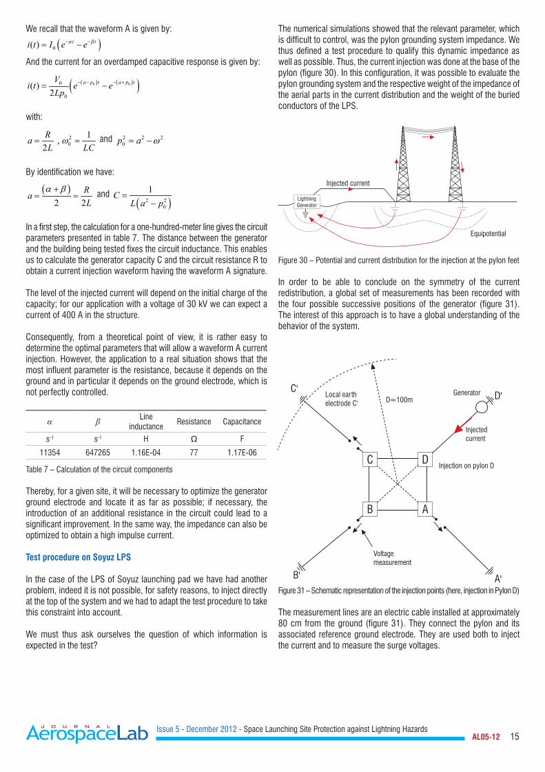
The numerical simulations showed that the relevant parameter, which is difficult to control, was the pylon grounding system impedance. We thus defined a test procedure to qualify this dynamic impedance as well as possible. Thus, the current injection was done at the base of the pylon (figure 30). In this configuration, it was possible to evaluate the pylon grounding system and the respective weight of the impedance of the aerial parts in the current distribution and the weight of the buried conductors of the LPS.
LightningGenerator
Injected current
Equipotential
Figure 30 – Potential and current distribution for the injection at the pylon feet
In order to be able to conclude on the symmetry of the current redistribution, a global set of measurements has been recorded with the four possible successive positions of the generator (figure 31). The interest of this approach is to have a global understanding of the behavior of the system.
C
B
D
A
Generator
Injectedcurrent
Local earthelectrode C'
Injection on pylon D
Voltage measurement
D≈100m D'C'
B' A'Figure 31 – Schematic representation of the injection points (here, injection in Pylon D)
The measurement lines are an electric cable installed at approximately 80 cm from the ground (figure 31). They connect the pylon and its associated reference ground electrode. They are used both to inject the current and to measure the surge voltages.

Issue 5 - December 2012 - Space Launching Site Protection against Lightning Hazards AL05-12 16
Measurement line
Figure 32 – Injection and measurement line
The injected current is measured in the four injection configurations. For each configuration, the overvoltages have been measured on the 3 other pylons. Voltage measurements have been based on the same local reference principle, using the same cables as for current injection. The voltage measurement was obtained by opening the cable at the level of the pylon (figure 34).
The constraints of the Soyuz launching pad environment do not make it possible to place the reference ground electrode of the generator in perfectly symmetrical position relative to the LPS the figure 33 presents the actual positions of the four ground electrodes for the four injection positions.
60.00
Pylon
D'C'
B'A'
AB
C
D
60.0
0
B'
A'
D'
C'
Figure 33 – Injection and measurement line
Figure 34 – Current and voltage measurement
Evaluation of the grounding impedance
Preliminary work consisted in the implementation of four reference ground electrodes, almost identical in regard to voltage measurements and current injection. The installation of identical reference ground electrodes would facilitate the analyses carried out later on. The injected current in the four configurations is shown in figure 35. The recordings show that the four injection configurations are completely comparable. An example of the voltage measured is presented in figure 36. The curves correspond to the overvoltage in Pylons A, B and C for an injection in Pylon D.
Tir 8.1 Injection ATir 22.2 Injection BTir 18.2 Injection CTir 10.1 Injection D
700
600
500
400
300
200
100
0
-100
Ampl
itude
(A)
Time (s)-1.0E-05 0.0E+00 1.0E-05 2.0E-05 3.0E-05 4.0E-05 5.0E-05
Figure 35 – Injected current in the four configurations
Va correctedVb correctedVc corrected
10
0
-10
-20
-30
-40
-50
-60
Ampl
itude
(V)
Time (s)0.0E+00 2.0E-05 4.0E-05 6.0E-05 8.0E-05 1.0E-04 1.2E-04
Figure 36 – Voltage measurement
For each injection position we have a measurement of the associated overvoltage in the three other pylons. Thus, we can define a coupling impedance between the voltage measured and the injected current (Zm). This impedance provides information on the grounding of the pylons but what about exactly of this measurement.

Issue 5 - December 2012 - Space Launching Site Protection against Lightning Hazards AL05-12 17
I0
Z1 Z2 V
Z12
Figure 37 – Electrical diagram used for the determination of the coupling impedance
For a given voltage measurement, the equivalent electric diagram of our coupling impedance is given in figure 37; its value is given by:
12
1 2 1 2
11 1mZ
ZZ Z Z Z
=+ +
On the one hand; the above formula shows that the coupling impedance is high in three cases that can be independent: for a high value of the impedance Z1, a high value of the impedance Z2 or a high value of the Z1×Z2 product, compared to the impedance value Z12 (Z1Z2 > Z12). On the other hand, Zm is small for a low value of Z1 or a low value of Z2, or a low value of Z1×Z2 compared to Z12.
In fact, the value of the coupling impedance cannot be higher than the lowest value of the impedances Z1 and Z2. To find low values of these impedances, as shown in table 8 and table 9, we can either have low values of the grounding impedance or a strong value of the connection impedance (Z12) between the pylons.
In the test, the measured coupling impedances are low. Consequently, for the lightning protection system analysis, we must differentiate between the interconnection impedance behavior and the ground electrode behavior.
Impedance (Ω)
A B C D
Injection A -6.6E-3 -3.4E-3 -19.3E-3
Injection B -6.5E-3 -11.8E-3 -6.6E-3
Injection C -3.3E-3 -12.6E-3 -18.4E-3
Injection D -21.6E-3 -7.2E-3 -19.1E-3
Table 8 – Static coupling impedance (f=0 Hz)
6.6 mΩ
6.6 mΩ
18 mΩ
19 mΩ
19 mΩ 21 mΩ
A B
CD
12 mΩ12.6 mΩ
Figure 38 – Diagram of the coupling impedance (static)
Impedance (Ω)A B C D
Injection A 64.0E-3 26.5E-3 64.7E-3
Injection B 63.1E-3 73.5E-3 28.7E-3
Injection C 26.3E-3 81.1E-3 92.1E-3
Injection D 71.3E-3 30.0E-3 89.9E-3
Table 9 – Dynamic coupling impedance
64 mΩ
63 mΩ
90 mΩ
92 mΩ
64 mΩ 71 mΩ
A B
CD
73 mΩ81 mΩ
Figure 39 – Diagram of the coupling impedance (dynamic)
By construction, we know that the pylons are interconnected, by both the aerial parts of the lightning protection system and the pylon interconnections buried within the ground. Due to this status, the values of the connection impedances cannot be large. With this assumption and the measured values of the coupling impedances, we can say that the impedances of the pylon grounding system are low and with the symmetry of measurements these values must be equivalent.
The difficulty is to determine the value of the main impedances of the system circuit model with the experimental data available. The number of measurements being limited, the system that we will try to solve must be simple. In the first order approximation, the circuit is presented in figure 40, with a grounding resistance for each pylon and connecting resistances between pylons.
To solve this problem, we have six measurements of the coupling impedances and eight resistance values to evaluate.
B
Vb
Vc
Va
Vd
RbIinjRa
R1
R4 R2
R3
Rd Rc
A
D C
Figure 40 – Simple electrical diagram for the measurement analysis

Issue 5 - December 2012 - Space Launching Site Protection against Lightning Hazards AL05-12 18
The problem is underdetermined and the number of solutions is thus important. However, by carrying out a research of solutions by a minimization algorithm, we can show that the pylon grounding resistances are low, whatever the impedance values between the pylons may be (figure 41).
This result is also important because it shows that the grounding resistances are comparable whatever the pylon, which confirms the raw experimental measurements.
Solution n°1
Solution n°2
Solution n°3
Solution n°4
Solution n°5
Solution n°6
R1
Impe
danc
e (O
hm)
R2 R3 R4 Ra Rb Rc Rd
6
5
4
3
2
1
0
Figure 41 – Impedance values after the optimization process
This kind of analysis makes it possible to study the dynamic quality of the pylon grounding system. This analysis is supplemented by the study of the local distribution of the currents. Indeed, the grounding system is not a single system. A pylon on the Soyuz launching pad is composed of three main reinforcements bar, which are connected to the grounding system in three different ways (figure 42), namely:
• a local ground termination system;• a local buried connection connected to the building grounding
system;• a buried connection connected to a ring ground electrode of
the site.
II
II
I
I
M3 M2
M1
Local ring earth electrode (a)
Local earth termination (c)
Link to the ring earth electrode of the site
Pylon foundation block
Bare copper 120 mm²
To the main building (d)
Figure 42 – Different types of grounding systems for a pylon
The currents recorded on the three bonding connections of the ground of the Pylon B (reinforcement N° 3) gives us a lot of relevant information (figure 43). It is the anchorage of the pylon which drives the maximum of current. This result is logical, the anchorage being connected to the local ring ground electrode, which is itself connected to the grounding circuit of the main building; this circuit impedance is obviously the lowest.
The share of current in the connection wire with the site ring ground electrode is less important and it drives a current at higher frequencies.The local ground electrode drives a low current but with high-frequency components.
This example clearly shows the behavior of a grounding system; at low frequencies, the entire grounding system drives the current whereas, at high frequencies, the local grounding system becomes predominant for draining the current.
250
200
150
100
50
0
-502.0E-050.0E+00 4.0E-05 6.0E-05 8.0E-05 1.0E-04 1.2E-04 1.6E-04 1.8E-04 2.0E-04
Curr
ent (
A)Time (s)
1.4E-04
Anchorage current
Link to the ring earth electrode of the site
Local earth electrode
Figure 43 – Current on the bonding connections to the grounding system
Currents in power lines
With this experimental protocol we can obtain other information on the behavior of the site during a lightning strike. Overvoltages induced by the current injection on the pylon ground electrodes will induce a current on all of the external metallic links of the site area. We can mention, for example, the LOX pipelines, but also the power cables. This is all the more important because the current in these connections can induce significant perturbations inside the building.
Let us for example take a look at the power supply cable of the Soyuz launch pad. This connection consists of an armored cable, which ensures the mechanical and electric protection of the power line. The shield of the cable is connected to the ground in the power room inside the building but, for practical reasons, it is not connected to the LPS. In the building, the power line is placed inside metallic cable trays. Inside the building, we have two types of EM shields around the power line: the first shield is the mechanical shield of the cable, the second shield is provided by the cable trays (figure 44). From the inside of the building (figure 45), the cable seems to be perfectly shielded, which gives the impression that it cannot generate a disturbance!
However, the current measured around the cable tray is of about two amperes for an injected current of 500 amps in Pylon B (figure 46). This value is rather important and it is mainly the result of a bad connection between the cable shield and the lightning protection of the building (figure 47).
Shielded cable current
Current measurement
Cable trays
Power cable
Figure 44 – Power line inside the cable tray

Issue 5 - December 2012 - Space Launching Site Protection against Lightning Hazards AL05-12 19
HT1
HT2
Figure 45 – Power cable trays inside the building
Current HT2
Current HT1
0.0E+00 5.0E-05 1.0E-04 1.5E-04 2.0E-04Time (s)
Curr
ent (
A)
2.5
2.0
1.5
1.0
0.5
0.0
-0.5
Figure 46 – Current measured around the cable tray of the power line
Power line shieldCable tray
Current
LPS
Figure 47 – Disturbance generated by the shielding current
Conclusions
The lightning protection solutions applied on the launch pad must comply with the requirements of any type of industrial site. However, the specificity of the launching pad installations requires a particular analysis suitable for the launcher protection before lift-off and for the seconds after lift-off.
In some phases of the launcher life cycle, lightning protection can only be provided by weather forecasting, which requires an efficient lightning alarm network.
However, the most significant risk is still a lightning strike in the phases before lift-off, when the launcher is on its launching pad. Indeed, the duration of this phase is significant and cannot be covered by weather forecasting.
At the present time, there are various solutions; these solutions often depend on the launcher itself and on the launching procedures.
The first solution is a protection starting with a removable gantry, which can be used for lightning protection as well as for protection against bad weather conditions. However, during the few hours, or even the few days, before launching, the gantry is removed and another protection system is absolutely required. This independent protection system is made up of several lightning conductors. The international standards based on the use of the electro-geometric model will impose a solution with three or four lightning conductors.
The protection system cannot however be summarized by the lightning conductor function. Due to electromagnetic coupling, a large number of devices are sensitive to the lightning current. For example, we can mention the propellant stored in the rocket, the pyrotechnics devices, electronic devices for launching management and, of course, the payload.
Thus, indirect lightning criteria are included in the dimensioning of the lightning protection system, in order to minimize the magnetic field in the launcher area. We must thus find a balance between positions close to the pylons, to satisfy the electrogeometric model, while keeping a low level for the magnetic field.
The first option to minimize the electromagnetic field is to use the separation function principle. In this case, we have insulators between the pylons and catenary wires, which drive the lightning current far away. However, it is difficult to ensure the efficiency of this solution for a strong lightning current.
The second solution is to use the pylon as a lightning down-conductor. In this case, to minimize the magnetic field in the launcher area, we must obtain a good balance of the current distribution on the pylons. The current balance is made first with multiple wire connections at the top of the pylons and second by a good grounding system for each pylon.
It is difficult to qualify the behavior of ground electrodes only with local experiments and, in particular, their behavior in regard to lightning current impulses. However, using complementarities of numerical simulations and experimentations, it is possible to qualify the quality of the grounding system and the impact on the current distribution, which allows an estimation of the magnetic field in the launcher area.
Finally, an on-site instrumentation of the site with a series of current and magnetic sensors would allow the monitoring of the actual lightning activity on the site and the assessment of the magnetic field mitigation n
Acknowledgements
The authors would like to thank Mr Phippe CUROT (CNES France) for his support for this work
Issue 5 - December 2012 - Space Launching Site Protection against Lightning Hazards AL05-12 20
References
[1] S. SOULA – Electrical Environment in a Storm Cloud. Aerospace Lab Issue 5, December 2012.[2] K. BERGER, R. B. ANDERSON and H. KRÖNINGER – Parameters of Lightning Flashes. CIGRE Electra n° 41, pp. 23-37, 1975.[3] V. A. RAKOV and M. A. UMAN – Lightning Physics and Effects. Cambridge University Press, 2003.[4] R. H. GOLDE – Lightning. Academic Press, 1975.[5] R. B ANDERSON and A. J. ERIKSSON – Lightning Parameters for Engineering Application. CIGRE Electra n° 69, pp. 65-102, 1980.[6] CEI 62305 – Protection against Lightning. 2006.[7] P. LAROCHE and al. – Observations of Bi-Directional Leader Development in Triggered Lightning Flash. ICOLSE, 1991.[8] M. BECERRA, V. COORAY and F. ROMAN – Lightning Striking Distance of Complex Structures. IET Gener Transm. Distrib, January 2008.[9] L. DELLERA, E. GARBAGNATI – Lightning Stroke Simulation by Means of the Leader Progression Model. IEEE/PES, Long Beach California,1989.[10] J. C. WILLETT, D. A. DAVIES and P. LAROCHE – An Experimental Study of Positive Lightning Rocket Triggered. Atmos. Res. 51, pp. 189-219, 1999. [11] A. BONDIOU and I. GALLIMBERTI – Theoretical Modeling of the Development of the Positive Spark in Long Gaps. J. Phys. D: Appl phys., 1994. [12] P LALANDE – Study of the Lightning Stroke Conditions on a Grounded Structure. Phd Onera, 1996.[13] A.SCHAFFAR and J.L.DECIBIEUX – ESA Workshop on Aerospace EMC Florence, Italy, 2009.[14] S. DESHAYES, S. FARGEOT, A. SCHAFFAR, P. N. GINESTE – Calculs numériques des effets de la foudre sur l’ensemble de lancement Ariane 5 10t. CEM04 Symposium.[15] F. VANCE – Coupling to Shielded Cable Edward. A Wiley-Interscience publication.[16] L. GRCEV and al. – Lightning Current Distribution to Ground at a Power Line Tower Carrying a Radio Base Station.[17] E. BACHELIER and al. – Simulation 3D de grands systèmes complexes: application a la definition des systèmes de protection foudre des futures sites de lancement SOYUZ et VEGA. CEM, 2008.[18] W. RISON and al. – Lightning Air Terminals – Is Shape Important. ISEMC, 2004.[19] J. P. MARQUE – Essai de simulation de foudroiement du site de lancement ELA au CSG. Rapport Onera 22/6118, November 1989.
Acronyms
Cloud-to-Cloud (CC)Cloud-to-Ground (CG)Centre Spatial Guyannais (CSG)Electro-explosive device (EED)Electricité de France (EDF)LIghtining Resistive Inductive Circuit (LIRIC)
Liquid oxygen (LOX)Lightning Protection Level (LPL)Lightning Protection System (LPS)Electric Field Mills - Moulin À Champ (MAC)Partial element Equivalent Circuit (PEEC)Thunderstorm Occurrence (THOR)
François Issac obtained his Technical University Degree (DUT) in physics measurement in 1982, in Montpellier, France. He began working at Ecopol from 1983 to 1986 on lightning effects and he joined the Office National d’Etudes et de Recherches Aérospatiales (Onera) where he became involved in numerous large scale EMC experiments (in-flight lightning
tests on a Transall aircraft in 1987-1990; EMPTAC tests on EM Topology, 1993-1996; joint cooperation on mode stirred chambers with DERA, 1999-2000). Nowadays, his field of interest covers a large area, from low frequency to high frequency, mainly from an experimental point of view. He is co-author of numerous papers dealing with EM measurement validations carried out at Onera.
Elodie Bachelier is engineer in the EMC team of the Electromagnetism and Radar Department, at Onera Toulouse. She first studied applied mathematics, and prepared a PhD thesis on the modeling of diffusion effects of soils, with a FDTD method. In the EMC team, she works on the
improvement of the numerical tools dedicated to 3D electromagnetic coupling, for complex industrial problems. During the last ten years, modeling the effects of lightning on structures has been an important part of her topics of interest.
Daniel Prost got his engineering degree from INPG (Institut National Polytechnique de Grenoble) in 1991 and obtained his Ph.D on magnetic properties of superconductors, from the Paris Sud University at LPS (Laboratoire de Physique des Solides d'Orsay) in 1994. He has been working as a Research Engineer in different industrial companies (Schneider Electric,
Schlumberger), involved in different topics (circuit breakers, electric arc, magnetic sensors, simulation). He joined the French Aerospace Lab Onera in 2008 to more especially work on lightning indirect effects and other EMC concepts in the aerospace industry context.
Vincent Enjalbert is a lightning expert and test manager within the lightning department of DGA Techniques Aéronautiques since 1994. He is in charge of tests on systems. He has been led to perform and manage tests on the main civilian and military aeronautical programs. He is also in charge of test campaigns on ground structures.
Today, he is carrying out expertises to the benefit of military programs managed by the Direction Générale de l’Armement (DGA) of the Ministry of Defence.
Laurent Mohedano is responsible for the communication network activity for the "région Aquitaine" at APAVE SUDEUROPE. Highly experienced, for more than 20 years he worked on lightning protection. He has, in particular participated in the European project MESA which aimed at the development and the site testing of a lightning generator.
He has also written risk analyses and technical studies on lightning for the sites of VEGA and SOYUZ of the Guyana Space center. He had also provided risk analyzes and lightning technical studies of the VEGA and SOYUZ sites at the Guyana Space Center.
AUTHORS