space electronics inspection stop 5 good .morning… · space electronics inspection stop 5 good...
TRANSCRIPT

,,- , ... ........ --:-
SPACE ELECTRONICS INSPECTION STOP 5
Good .morning. My name is Sanford Jones. My associate Dave Wright and I
will show you some of the contributions to advanced space electronics and
in particular, the application to communications being made by the LeRC.
I will begin with a survey of the techniques presently being used in Com
munication systems. Up until the 1960's, information transmission across
oceans was limited to underwater cable and was used primarily for telephone.
On land, line-of-sight microwave towers were used to transmit television and
telephone traffic was handled through a vast network of land lines. Until
recently there was no television transmission across the oceans because of
the infeasibility of constructing microwave towers on water over the long
distances involved.
With the introduction of ,communications spacecraft, we have made a great
change in communications. In 1~64 ·th~ Olympics came from Japan and last
year from Germany. Last year we saw the President visit Peking. Last year
Brazil had six overseas telephone channels - this year 160. Early thi s year
there were four channels to Peking - none last year. Now you can direct dial
London and rates to Europe and Japan have recently been cut in half. Demand
is growing at the rate of 100% per year and is being stimulated by the need
for communication and trade. The world has now become much smaller because
of communication spacecraft. Lewis is working in several technology are as
that in the future will permit us to economically provide remote educational
and health services, to transmit economic, law enforcement, and postal data,
and to warn the populace of natural disasters such as hurricane or t ornado.
All present connnunications spacecraft are what we call the repeater type
and they are placed in synchronous orbit. A synchronous orbit is one tbut
remains over a point on the Earth. To demonstrate this idea, we have n model
of a TV communications system here on stage. On your right you see n. 'rV camera.
Here we have a transmitter and an antenna beaming a microwave signal to the
spacecraft overhead which is approximately half scale.

2
The spacecraft accepts the signal through its receiving antenna.
denoted by the blue dot. 'l'he signal is amplified and retransmitted to the
ground receiving station where the signal is converted and displayed. This
is an operational system and I can interrupt it with my hand.
All spacecraft have been limited to transmitting power of only a few
watts. This requires very sensitive ground receivers. Here we have a plot
of ground station costs versus effective spacecraft power. As we can see,
even present dey s/c as represented by Intelsat IV require receivers far
too costly for small users such as small medical clinics, schools, small
city police stations, businesses, etc. However, there are two spacecraft
which are to be launched in the near future which permit relatively inex-
pensive ground terminals. These are the Applications Technology Satellite F
and the Connnunications Technology Satellite. The ATS-F is a NASA-sponsored
satellite and the CTS is a joint .ye.nt1;1re between the United States and
Canada and is managed for NASA by the Lewis Research Center. Both satel-
lites will be used to conduct communications experiments. The initial
experiments on ATS-F will be conducted with ground receivers in the United
States. Later the satellite will be moved to a position over India where com;nunity
television programs will be broadcast directly to/receivers located in each
village. The CTS experiments will be conducted in the remote northern
regions of Canada and Alaska and remote areas of the United States.
Here we have a picture of the ATS-F satellite. The satellite uses a
20-watt transmitter and a 30-foot diameter antenna, and it will provide a
signal streng~h adequate for low cost ground stations to an area about the
size of Ohio. Here we have a picture of the CTS satellite. This uses a
200-watt transmitter and a 2-1/2 foot diameter antenna that will
provide about the same signal strength as the ATS-F satellite but over an

3
area about 1/3 the size of the UnHed States. In these high power spacecraft
efficiency of the various spacecraft systems becomes very important. The
Lewis Research Center has been conducting several technology programs that
contribute to the efficiency and utility of these communication spacecraft.
We will describe five of them: our work in high efficiency amplifier tube
technology - high voltage phenomena - contoured beam antenna - solar array
technology - and thrusters for station keeping.
Here is a diagram of the high efficiency amplifier tube to be used on
CTS. Power is provided from a solar array. A powerful electron beam is
formed which emerges into an interaction region. This power is then used
to amplify the input signal for retransmission back to Earth. It is what
we do to the electron beam as it emerges from this interaction region that
is new and more efficient. In previously used amplifier schemes, there was
only a single collecting element so that as the electrons emerged from this
interaction region at different velocities, large amounts of heat were
generated on the collector surface. We have studied this electron beam
and found that it resembles water droplets emerging from a fountain. If
it were possible to catch the water droplets at a time or instant when they
stop, there would be no splashing. Analogously, if it were possible to
catch the electrons when they stop, there would be very little heat gen-
erated and the efficiency would be increased. To accomplish this, we have
designed a set of carefully spaced and shaped collectors.
Here we have a model of a multistage collector. The size of the hole
in the center and the shape of the plates are determined from rather
sophisticated computer calculations.

, 4
To demonstrate the effect of using a multistage collector, we show here
the efficiencies of a single collector system and that of a multicollector
system. In previously used schemes, only 20% of the input power was con-
verted to useful RF output signal and the remainder was dissipated as heat.
With the multistage collector system, we now obtain 2~ times as much output
power.
bility.
Now with each s/c we can provide 2l times the communication capa-2
This can be used to drastically lower ground station costs; or to
provide more channels and also lower the cost to use a channel.
Over here we have a model of the amplifier tube that will be used on
the CTS spacecraft. In this part, we have the electron gun - here is the
interaction region and within this can-like enclosure is the multistage "
collector. Now the fact that we have enclosed this collector suggests
another area of research being conducted by the Center. Ideally, it would
be better not to have the collector· e~closed so that dissipated heat could
be radiated directly into space. Because space is a very good vacuum and
therefore a good insulator, this should work; ha;rever, upon closer examinawith
tion, we find that space is filled / many positively and negatively charged
particles which we call a plasma. The spacecraft must operate while being
immersed in the plasma and it is possible that exposed collector plates
that operate at very high voltages might be short circuited. We have
a diagram that illustrates the situation. Here we see a spacecraft with
high voltage elements which must operate while being irranersed in the plasma.
Here we have a solar array wired to directly produce the high voltage
needed by the tube, and here the high voltage amplifier tube and its set of
multistage collectors. The possible short circuiting paths caused
by the plasma are depicted by the large arrows.
In order to obtain information, we conducted ground-based experiments
in vacuum chambers similar to the one you see behind you. However, we

5
encountered two di f f i cultie s. ade quately
We could not /r eproduce the space plasma and
we had diff i culty with the proximity of the vacuum chamber walls affecting
the conduction of the pla sma path. In order to obtain the data needed on
the resistance of a spacecraft i mmersed in a plasma, we have designed a
spacecraft which wi ll be launched early next year. We call this spacecraft
SPHINX, which is an acronym for space plasma high voltage interaction
experiment. We have a mcxlel of the spacecraft here on stage. The space-
craft consists of solar arrays to produce power,cornmunication antenna,
attitude control thrusters and the expe riments. The multi-electrode experi-
ment is directly analogous to the multistage collector. We will
also conduct an experiment on the effic iency of a higti voltage array. This
spacecraft will be launched early next January on a Titan-Centaur launch
vehicle. The experiments will be conducted over a period of one year. The . ··.:·
orbit is a long e llipse which will provide a wide range of plasma concentra-
tion. And now I would like to introduce to you Dave Wright who will con-
tinue our discussi on on Lewis Research Center endeavors in space electronics.

Good mornin g . The next technology area that I wi I I discuss is contoured
beam antennas. Conventional parabolic reflector antennas such as those
used on the ATS-F and CTS and as s hown on the spacecraft overhead produce
circular or elliptical patterns, These antennas are ideally suited for
point-to-point communications, However, when we try to cover an irregular
area such as Alas ka , these antennas waste power, In this chart, we show
the problem. Here we have the earth and a satellite in synchronous orbit
using a circular beam antenna to provide the coverage pattern. As you can
see, the radiation pattern which is shown by this dotted I ine just manages
to encompass the en tire state of Alaska on al I the corners; however, in order
to do this, a sub stantial amount of power is wasted and radiated into such
areas as the Pacific ocean and over the horizon, not even intercepting the
earth. For this ca se, of all the power radiated from the spacecraft only 17%
actually falls upon the land surface of Alaska. The second problem with
these circular beam antennas is that they create a possible problem of in
terference, In t he example here, the wasted power fell harmlessly into the
Pacific ocean or over the horizon. However, if our example would have been
say Appalachia inst ead of Alaska, this wasted power would have appeared as
unwanted power in the entire eastern United States. It could have interfered
with existing terr estrial communications and other satellite communications.
In order to overcome these problems of circular beam antennas, we are
investigating wha t we call contour beam antennas. Here you can see the same
area, Alaska , be ing covered by fiv e smal )er radiation patterns. These patterns
are provided by a contoured beam antenna which is shown by this model, It
uses five feed ho rn s arranged on a sin g l e reflector to produce the radiation
pattern. Each on e of these feed horns produces one of the five radiation
patterns. The co111 pos i te of the se ind iv i dua 1 patterns produces the coverage
defined by this contour.

2
As you can see, we have
reduced substanti a lly the amount of power that is radiated into the Pacific
ocean and also th e amount of power that is radiated over the horizon. This of
system is about 33% efficient, in other words/all the power radiated from the as compared
spacecraft approximately 33% of it falls on Alaska as usable power/ This with 17% for a cir cular beam. approximately dou b les the communication capability and ultimately results in
lower costs for t e lephone and television time.
The next tec hnology area that I will discuss is solar array technology.
The ATS and the CTS spacecraft which we have described use solar cells to
derive their elect rical energy from sunlight. As you remember, the present
trend in communica tion systems is toward higher power as Sanford has pointed
out - the CTS spacecraft will radiate 200 watts, while the ATS spacecraft
only radiated 20 watts. You can see from our pictures the substantial in-
crease in the si ze of the solar arrays in CTS as compared with the ATS
spacecraft. Since the size of the solar arrays are increasing drastically
with time, it is important that we increase the efficiency and reduce the
cost of solar ar ra ys.
The diagram s hows a cutaway of a typical solar cell - the semiconductor
layers - the el ect rical cont acts - and the various coatings and radiation The pres ent efficiency is 11 %.
protection/ The maximum theoretical e fficiency of a solar cell is approximately
22%. Our goal i s to raise the effici ency to better
18%. In order t o do this, we are investigating/anti-reflective coatings

- ~ · - . .
3
which will allow more sun] ight to enter the cell and cause Jess to be re-
fleeted. We are a lso providing better electrical contact to the eel Is to
reduce
electrica l losses. If we can achieve our efficiency goal of 18%,
we can provide 50% greater communication capability aboard each spacecraft
which translates into more channels and lower cost per hour to rent a chann~l.
We plan to reduce the cost of assembling solar arrays by simplifying
the method of providing for protection from radiation damage. At present,
each one of these glass covers has to be individually cemented in place and
this is very time consuming and raises the cost of the arrays appreciably.
We are studying a process that uses a large plastic sheet to encapsulate
many cells into one module such as the one you see here. This process of
taking a large pl astic sheet and sandwiching it together with the cells and
a plastic substra t e is a process much like you would make a plastic identifi-
cation card or credit card. As you can see, the model is quite flexible and
lends itself to an unfolding array such as we have shown on this model on
stage. With this technique, we can reduce the cost of large arrays by about which might require a 10 kW solar array
25%. On a 5000 pound spacecraft for example/the savings would be 1 mill ion
dol Jars which could provide 100 extra ground stations.
The last technology area that I wil I discuss is station keeping technology.
All of the spacecraft which we have des c ribed will be placed in synchronous
orbit. This mean s that they appear stationary over the earth. However,
there are force s r rom the sun, the moon and out of roundness of the earth which
cause these spacec ra f t to drift about from the desired position. Therefore,

4
it is nec es sary to include thrusters, such as you see on each end of the to keep the spacecraft over the desired point .
spacecraft as den oted by the red dots/ At the present time, all spa~ecraft
use chemical thru s ters for this station keeping maneuver. In order to derive
their thrust, these chemical thrusters actually expel gas particles under
pressure. This i s a very inefficient process because the particles are
emitted at a fairly low velocity. In the future, we foresee the possible
use of ion thrust e rs for this station keeping maneuver and one such thruster is
shown here on sta ge. This ion thruster creates its thrust by expel] ing charged
particles or ion s from this grid area using an electric field. Because
this electric fi e ld accelerates these particles to a much higher velocity,
the ion thruster makes much more efficient use of its propellant. I might
point out that t he ion thruster produces only about l/ 60 of an ounce ~f
thrust; however, even used intermittently this is sufficient for station
keeping small to medium size spacecraft. station keeping
On this char t , we have a comparison between the'efficiency of the
chemical thruster and the ion thruster. As you can see on this vertical
axis, we plot the weight of the thruster system and its propellant as a percent
of spacecraft wei ght and on the horizontal axis we plot the years in
synchronous orbi t. The empty weight of the two systems is indicated by the
zero years in or b i t point and you can see that the empty weight of the chemical
thruster and the ion thruster are approx imately equal. The incr ease in each
curve then indi cu tes the amount of propellant that must be initi d lly pro-
vided to do the s tation keeping job for the years indicated, For
a ten-year mis s ion , the ion thruster and propellant comprises on ly about 8% in i t i a 1
of the total/spacec raft weight. On the other hand, the chemical thruster in it ia 1
a nd propc l L:i nt c.<1111 pr i scs a pprox i111<:1tc ly 2'.J '/. of thc/ c;p.::iccc r0fl wei <Jht. At the

. ,,
present time, mi ss ions are tending toward these longer times because this
reduces the cost per year of the spacecraft. The savings we can obtain
5
with an ion thrus t er, as shown, could increase the communications capability
by 50% which again translates into more channels or lower cost per minute
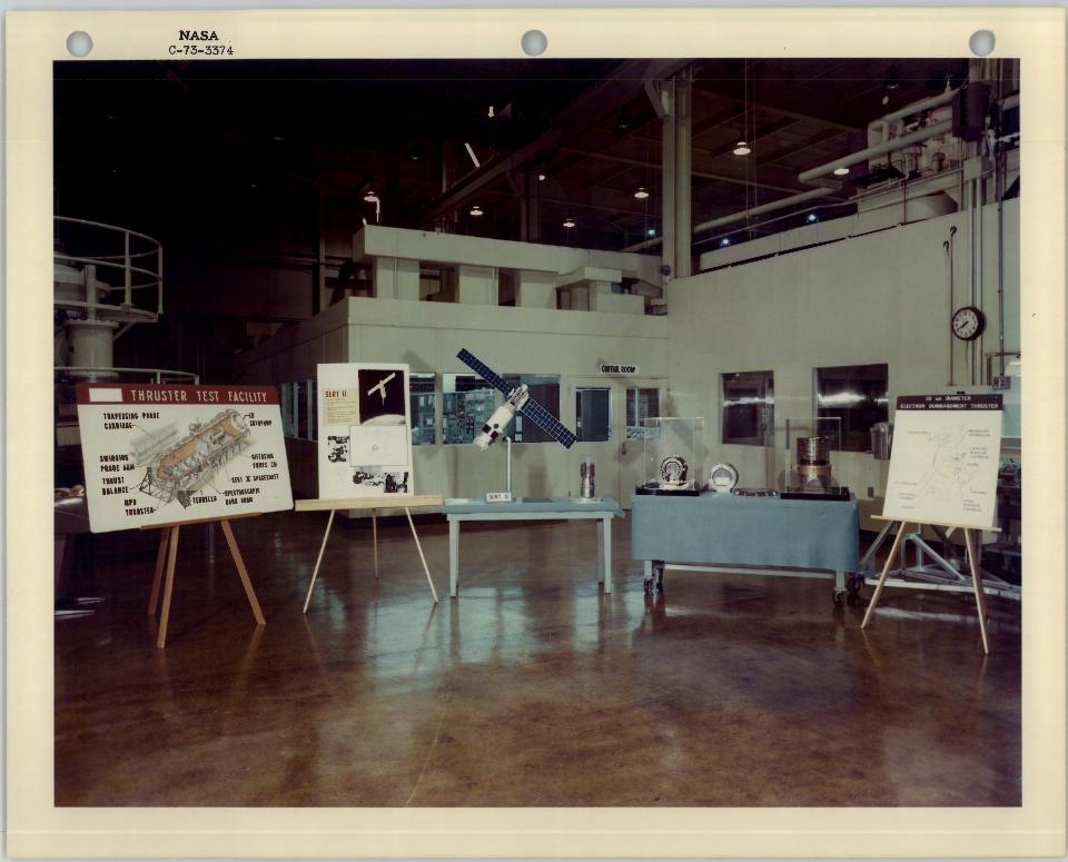
or hour for rent of these channels. Besides this small ion thruster which
have talked about, we are also studying larger ion thrusters such as you
see in the pictures and displays on the left. These ion thrusters can produce approx
imately ~ounce of thrust and are sufficient to station keep a large
satellite or can be used for interplanetary propulsion.
In summary, we have described the five following areas of technology -
high efficiency, h igh power microwave amp] ifiers, high voltage s pace tech
nology, contoured beam antennas, more efficient solar arrays and we have
shown the advantages of ion thrusters for long life station keeping. The ap
plication of these five areas of technology will result in increased com
munications covera ge in the form of lower cost ground stations, more channels
or lower cost cove rage to remote areas such as Alaska. Specifically, we
foresee low cost communications systems having the fol lowing direct benefits
for mankind. Benefits wi 11 appear in the areas of medicine and health,
education, law en fo rcement, postal distribution and disaster warning. Thank
you.

1 ~TOP 5 EkRE;T HURST 4110
C 6771fS (SPACE/EARTH COMMUNICATIONS)
cs 6778@ PAST-PRESENT AND FUTURE
CS 677813) GROUND STATION COST AS A FUNCTION OF SPACECRAFT POWER
cs 67782'> TECHNOLOGY AREAS
cs 677, HIGH EFFICIENCY AMPLIFIER
cs 67~ cs 6778ri>
c 6778'
cs 67787>
cs 6778~> cs 67789>
cs 67798
...
TUBE EFFICIENCY
CURRENT LEAKAGE PATHS SURROUNDING A SPACECRAFT
CIRCULAR BEAM OVER ALASKA
CONTOUR BEAM OVER ALASKA
SOLAR CELL IMPROVEMENTS
THRUSTER SYSTEM WEIGHT COMPARISON
SPACE ELECTRONICS RESEARCH AND TECHNOLOGY
...
·.
. ....
-I

...
,, , '•
·~
·"
...... '"""'' -----1 I I
OCEAN CABLE -1
PAST •OLYMPICS
- JAPAN 1964
- MEXICO 1968
- GERMANY 1972
• PRESIDENTIAL VISIT TO PEKING
C.H,l\RI 1-
PRESENT • BRAZIL - 160 OVERSEAS
TELEPHONE CHANNELS (LAST YEAR -6)
• CHINA - 4 OVERSEAS TELEPHONE CHANNELS (LAST YEAR -0)
e DIRECT DIAL LONDON
e RATES CUT 253 TO EUROPE & JAPAN
• 16,000 TELEPHONE CHANNELS ACROSS ATLANTIC (24 COLOR TV)
e 8000 TELEPHONE CHANNELS ACROSS PACIFIC (12 COLOR TV)
e 2 MORE SPACECRAFT RECENTLY LAUNCHED -INCREASE CAPACITY S03
CHART 2
.,
SToP b
(cS-fo777'i)
FUTURE e 1003 INCREASE
PER YEAR
e TRADE
e MEDICAL I e EDUCATIONAL
e LAW ENFORCEMENT I
e POSTAL
e DISASTER WARNING I I
• GOALS I - IMPROVE CAPABILITY - LOWER COSTS
I TECHNOLOGY
t

c
GROUND STATION COST AS A FUNCTION OF SPACECRAFT POWER
GROUND STATION DOLLARS
COST
100,000,000
10,000,000
1,000,000
100,000
10,000
1000
SYNCOM ~ • INTELSAT I K
EFFECTIVE SPACECRAFT POWER -
(cs-~7?eJ)
TECHNOLOGY AREAS
• EFFICIENT HIGH POWER MICROWAVE AMPLIFIERS
e HIGH VOLTAGE SPACE TECHNOLOGY
• CONTOURED BEAM ANTENNA
e IMPROVED LOW COST SOLAR ARRAY
• LONG LIFE ST A TION KEEPING
( CS-6'1?6 2..)
...
.. . . . .
l

I
I~
HIGH EFFICIENCY AMPLIFIER
\ I
COLLECTORSl~ \~
\----......
SIGNAL_
OUTPUT J INTER _
ACTION
SIGNAL REGION INPUT - ...._ _ ___.
ELECTRON GUN
CH~~T 5
TUBE EFFICIENCY
SIGNAL POWER ~,
400 WATTS
HEAT ./
\ \
203 EFFICIENT
CHART (o
SIGNAL POWER ~,
400 WATTS
503 EFFICIENT
I

CURRENT LEAKAGE PATHS SURROUNDING A SPACECRAFT
SPACE PLASMA
HIGH VOLTAGE SOLAR ARRAY '
\
\
CHARI I
SPACE PLASMA
cs -{:,?'J85
I

• .
CHARr lo
.•
" ,, J
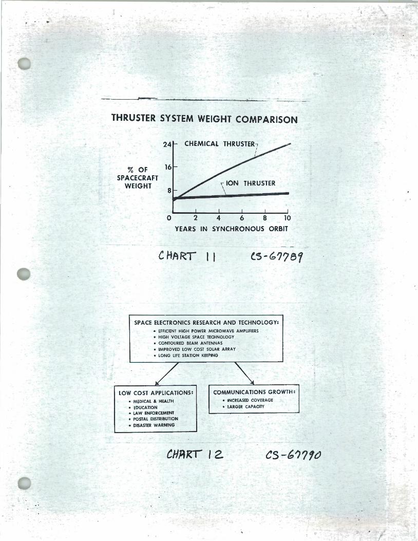
THRUSTER SYSTEM WEIGHT COMPARISON
24 CHEMICAL THRUSTER-,
16
, ION THRUSTER
3 OF SPACECRAFT
WEIGHT I
8~~--~\---------0 2 4 6 8 10
YEARS IN SYNCHRONOUS ORBIT
CHART 11
SPACE ELECTRONICS RESEARCH AND TECHNOLOGY: • EFFICIENT HIGH POWER MICROWAVE AMPLIFIERS • HIGH VOLTAGE SPACE TECHNOLOGY • CONTOURED BEAM ANTENNAS • IMPROVED LOW COST SOLAR ARRAY
• LONG LIFE STATION KEEPING
LOW COST APPLICATIONS: COMMUNICATIONS GROWTH:
• MEDICAL & HEALTH • INCREASED COVERAGE
• EDUCATION • LARGER CAPACITY
• LAW ENFORCEMENT • POSTAL DISTRIBUTION
• DISASTER WARNING
CHRRr 12. es-6??1o
. . > /

------
l •
-...-
.__
. .....
. . ---
----
-----
. , .
..
\.r;
::=
.==
-
\


>-0:: 0 J<
( 0:: 0 m
<
( ...J
z 0 -(/) ...J :l a.. 0 0:: a.. u -0:: Ju w
~
...J <~
w
U)
I
<"'
z"i
. u