sp20005 rev 4 - dennisuk.com · 3 premier sp20005rev4 certificate of conformity cylinder mowers...
TRANSCRIPT

PREMIER RANGE
DENNIS, Ashbourne Road, Kirk Langley, Derby, DE6 4NJ, United KingdomTelephone:- 01332 824 777
Fax:- 01332 824 525E-mail:- [email protected]
E-mail:- [email protected]
www.dennisuk.comSP20005_REV_4
11/15
INSTRUCTION MANUAL

Serial Numbers
FT
R
azor
R
azor
Si
mpl
ex
G56
0 Su
perS
ix G
660/
G76
0 Pr
emie
r C
ontr
acto
r Bra
y H
and
S500
G
ang
App
licat
ion
R
ange
56
0 U
ltra
560
Ran
ge
G68
0 R
ange
G
860
Ran
ge
To
ols
Plus
M
ower
Bow
ling
Gre
en
ü
ü
ü
ü
ü
ü
ü
Cric
ket G
roun
d M
aint
enan
ce:
wic
ket
ü
ü
ü
ü
ü
ü
squa
re
ü
ü
ü
ü
ü
ü
outfield
ü
ü
ü
Foot
ball
Pitc
h
ü
ü
ü
Gol
f Cou
rse
Mai
nten
ance
: Te
es
ü
ü
ü
ü
ü
ü
ü
Gre
ens
ü
ü
ü
ü
ü
ü
Orn
amen
tal
ü
ü
ü
ü
ü
Cro
quet
Gre
en
ü
ü
ü
ü
ü
ü
ü
ü
Gra
ss T
enni
s C
ourt
ü
ü
ü
ü
ü
ü
ü
Rac
e C
ours
e M
aint
enan
ce:
P
arad
e R
ing
ü
ü
ü
ü
ü
ü
ü
Orn
amen
tal
ü
ü
ü
ü
ü
ü
ü
ü
Rug
by P
itch
ü
ü
ü
Hoc
key
Pitc
h
ü
ü
Spo
rts C
lub
Mai
nten
ance
ü
ü
ü
ü
ü
ü
ü
ü
ü
ü
ü
ü
Sch
ools
, Col
lege
s &
Uni
vers
ity G
roun
ds
ü
ü
ü
ü
ü
ü
ü
ü
ü
ü
ü
ü
Cem
eter
y M
aint
enan
ce
ü
ü
ü
ü
Con
tract
ors,
Priv
ate
Law
ns &
Com
mer
cial
ü
ü
ü
ü
ü
ü
ü
Loca
l Aut
horit
y &
Gov
ernm
ent C
ontra
cts
ü
ü
ü
ü
ü
ü
ü
ü
ü
ü
ü
ü
Orn
amen
tal L
awn
ü
ü
ü
ü
ü
ü
ü
ü
THIS
INFO
RM
ATIO
N IS
INTE
ND
ED
FO
R G
UID
AN
CE
PU
RP
OS
ES
ON
LY. W
E R
EC
OM
ME
ND
TH
AT Y
OU
DIS
CU
SS
YO
UR
SP
EC
IFIC
RE
QU
IRE
ME
NT
WIT
H O
UR
HE
AD
OFF
ICE
, SA
LES
MA
NA
GE
RS
OR
YO
UR
LO
CA
L D
EN
NIS
DE
ALE
R.
NO
TE
Prod
uct A
pplic
atio
n M
atrix
3Premier SP20005_REV_4
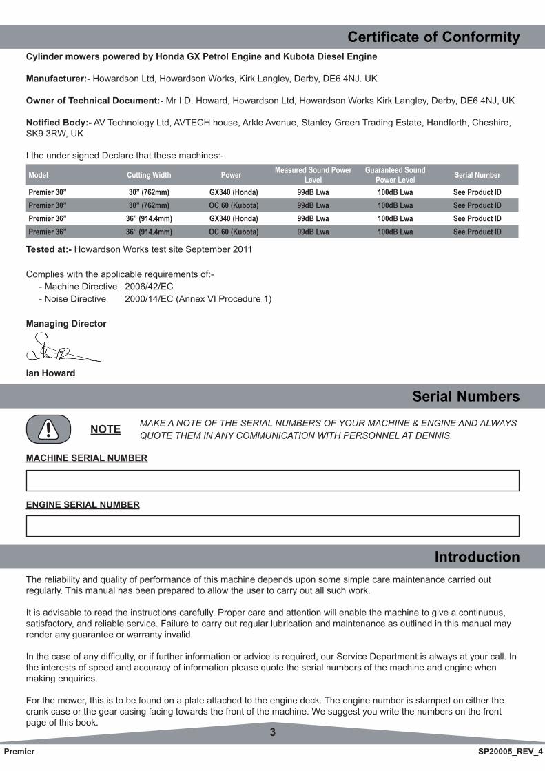
Certificate of ConformityCylinder mowers powered by Honda GX Petrol Engine and Kubota Diesel Engine
Manufacturer:- Howardson Ltd, Howardson Works, Kirk Langley, Derby, DE6 4NJ. UK
Owner of Technical Document:- Mr I.D. Howard, Howardson Ltd, Howardson Works Kirk Langley, Derby, DE6 4NJ, UK
Notified Body:- AV Technology Ltd, AVTECH house, Arkle Avenue, Stanley Green Trading Estate, Handforth, Cheshire, SK9 3RW, UK
I the under signed Declare that these machines:-
The reliability and quality of performance of this machine depends upon some simple care maintenance carried outregularly. This manual has been prepared to allow the user to carry out all such work.
It is advisable to read the instructions carefully. Proper care and attention will enable the machine to give a continuous, satisfactory, and reliable service. Failure to carry out regular lubrication and maintenance as outlined in this manual may render any guarantee or warranty invalid.
Inthecaseofanydifficulty,oriffurtherinformationoradviceisrequired,ourServiceDepartmentisalwaysatyourcall.Inthe interests of speed and accuracy of information please quote the serial numbers of the machine and engine whenmaking enquiries.
For the mower, this is to be found on a plate attached to the engine deck. The engine number is stamped on either the crank case or the gear casing facing towards the front of the machine. We suggest you write the numbers on the front page of this book.
Introduction
Serial Numbers
MACHINE SERIAL NUMBER
MAKE A NOTE OF THE SERIAL NUMBERS OF YOUR MACHINE & ENGINE AND ALWAYS QUOTE THEM IN ANY COMMUNICATION WITH PERSONNEL AT DENNIS.NOTE
ENGINE SERIAL NUMBER
Model Cutting Width Power Measured Sound Power Level
Guaranteed Sound Power Level Serial Number
Premier 30” 30” (762mm) GX340 (Honda) 99dB Lwa 100dB Lwa See Product IDPremier 30” 30” (762mm) OC 60 (Kubota) 99dB Lwa 100dB Lwa See Product IDPremier 36” 36” (914.4mm) GX340 (Honda) 99dB Lwa 100dB Lwa See Product IDPremier 36” 36” (914.4mm) OC 60 (Kubota) 99dB Lwa 100dB Lwa See Product ID
Tested at:- Howardson Works test site September 2011
Complies with the applicable requirements of:- - Machine Directive 2006/42/EC - Noise Directive 2000/14/EC (Annex VI Procedure 1)
Managing Director
Ian Howard
4Premier SP20005_REV_4
Contents PageProduct Application Matrix .................................................................................................................................................... 2Declaration of Conformity ..................................................................................................................................................... 3Serial Numbers ..................................................................................................................................................................... 3Introduction ........................................................................................................................................................................... 3Technical Data ...................................................................................................................................................................... 4Machine Description ............................................................................................................................................................. 5Important Safety Instructions ................................................................................................................................................ 6Controls ................................................................................................................................................................................ 7Operating Instructions ..................................................................................................................................................... 8 - 9General Adjustments ....................................................................................................................................................10 - 11Routine Maintenance................................................................................................................................................... 12 - 13Storage ............................................................................................................................................................................... 13 Parts Listings ............................................................................................................................................................... 14 - 29
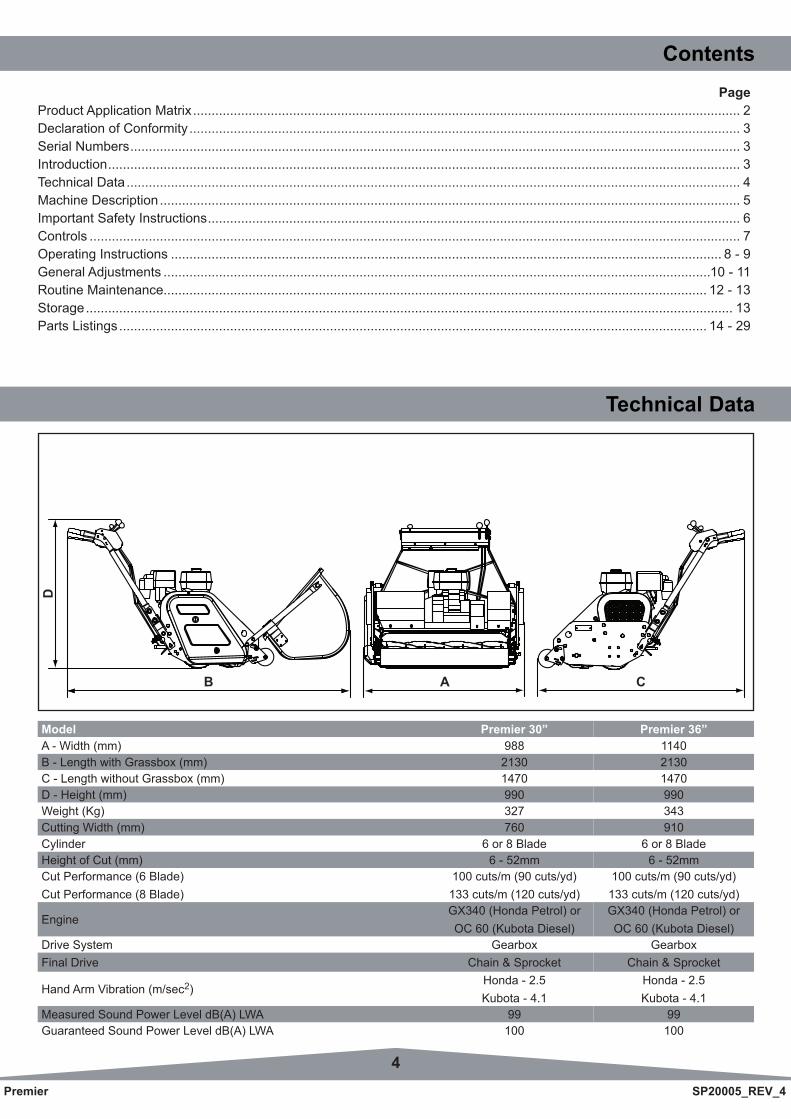
Technical Data
Model Premier 30” Premier 36”A - Width (mm) 988 1140B - Length with Grassbox (mm) 2130 2130C - Length without Grassbox (mm) 1470 1470D - Height (mm) 990 990Weight (Kg) 327 343Cutting Width (mm) 760 910Cylinder 6 or 8 Blade 6 or 8 BladeHeight of Cut (mm) 6 - 52mm 6 - 52mmCut Performance (6 Blade) Cut Performance (8 Blade)
100 cuts/m (90 cuts/yd) 133 cuts/m (120 cuts/yd)
100 cuts/m (90 cuts/yd) 133 cuts/m (120 cuts/yd)
EngineGX340 (Honda Petrol) or OC 60 (Kubota Diesel)
GX340 (Honda Petrol) or OC 60 (Kubota Diesel)
Drive System Gearbox GearboxFinal Drive Chain & Sprocket Chain & Sprocket
Hand Arm Vibration (m/sec2)Honda - 2.5 Kubota - 4.1
Honda - 2.5 Kubota - 4.1
Measured Sound Power Level dB(A) LWA 99 99Guaranteed Sound Power Level dB(A) LWA 100 100
AB C
D
5Premier SP20005_REV_4
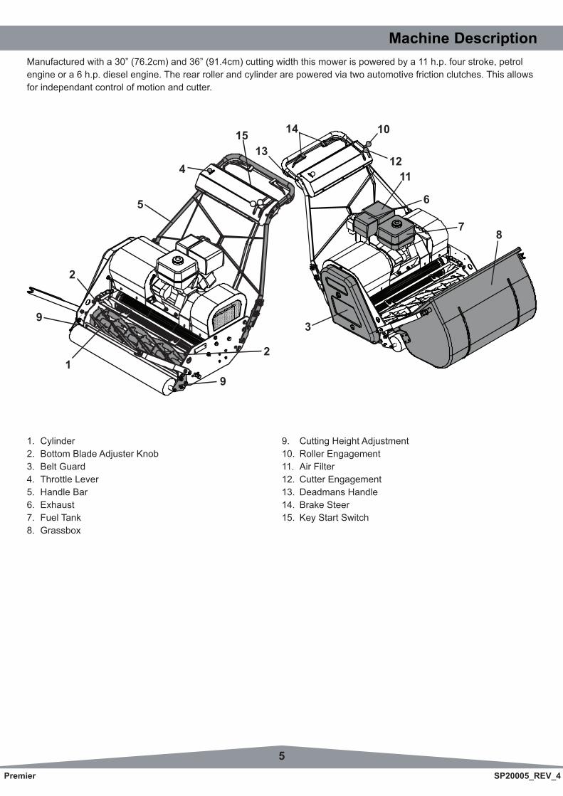
Machine DescriptionManufactured with a 30” (76.2cm) and 36” (91.4cm) cutting width this mower is powered by a 11 h.p. four stroke, petrol engine or a 6 h.p. diesel engine. The rear roller and cylinder are powered via two automotive friction clutches. This allows for independant control of motion and cutter.
1. Cylinder 9. Cutting Height Adjustment2. Bottom Blade Adjuster Knob 10. Roller Engagement3. Belt Guard 11. Air Filter4. Throttle Lever 12. Cutter Engagement 5. Handle Bar 13. Deadmans Handle6. Exhaust 14. Brake Steer7. Fuel Tank 15. Key Start Switch8. Grassbox
1
3
8
4
5 6
7
2
9
15
1112
14
13
2
10
9
6Premier SP20005_REV_4
Important Safety InstructionsIn order to operate the machine safely please follow these Health and Safety guidelines.
TRAINING
READ THE INSTRUCTIONS CONTAINED IN THIS MANUAL WITH CARE. IF YOU ARE IN ANY DOUBT PLEASE ASK YOUR EMPLOYER OR CONTACT US DIRECT AT DENNIS.CAUTION
• Be familiar with the controls and the proper use of the equipment.• Never allow children or people unfamiliar with these instructions to use the mower. Local regulations or insurance may restrict the age of the operator.• Never mow while people, especially children, or pets are nearby.• Keep in mind that the operator or user is responsible for accidents or hazards occurring to other people or their property.
PREPARATION
• While mowing always wear substantial footwear and long trousers. Do not operate the mower barefoot or in open sandals.• Thoroughly inspect where the equipment is to be used and remove all stones, sticks, wire, bones and other foreign objects.
PETROL AND DIESEL IS HIGHLY FLAMMABLE AND WILL DAMAGE GRASS IF SPILT.WARNING
A)Storefuelincontainersspecificallydesignedforthispurpose.B) Refuel out doors and do not refuel whilst smoking.C) Add fuel before starting the engine. Never remove the cap of the fuel tank or add fuel while the engine is running or when the engine is hot.D) If fuel is spilled do not attempt to start the engine but move the machine away from the area of spill and avoid creating any sources of ignition until the vapours have dissipated.
• Replace damaged or faulty silencers.• Before using the machine always inspect the safety devices including the cut off switch and the blades for excessive wear or damage. Replace if necessary.
OPERATION
• DonotoperatetheengineinaconfinedspacewheredangerousCARBON MONOXIDE fumes can collect.• Mowonlyindaylightorgoodartificiallight.• Avoid operating the machine in wet grass where feasible.• Always be sure of your footing on slopes.• Walk. Never run.• Walk across the face of slopes, never up and down.• Exercise extreme care on slopes when changing direction.• Do not mow excessively steep slopes.• Use extreme caution when reversing or pulling the machine towards you.• Stop the blades if the mower has to be tilted for transportation when crossing surfaces other than grass and when transporting the mower to and from the area to be mown.• Never operate the mower with defective guards or shields or without the safety devices, for example without the deflectorplateorgrassboxinplace.• Do not change the engine governor settings or overspeed the engine.• Disengage all blades and drive clutches before starting.• Start the engine carefully following the instructions with feet well away from the blades.• Do not tilt the mower when starting the engine.• Do not put hands or feet near or under rotating parts. Keep clear of the discharge opening at all times.• Never pick up or carry the mower while the engine is running.
7Premier SP20005_REV_4
ControlsFOR THE LOCATION OF CONTROLS AND COMPONENTS REF. “MACHINE DESCRIPTION” PAGE 5.
ON / OFF SWITCH (Item 17)
This key switch starts the engine and can be used to stop the engine at anytime during the operation of the machine.
DEADMANS CONTROL (Item 13)
This is an operator presence control. It must be raised before the cylinder or roller can be engaged and held in until the cylinder or roller is disengaged. Releasing the lever with the cylinder or roller engaged will cause the engine to stop.
BRAKE STEER CONTROLS (Item 14)
To help steer the machine, the rear roller is equipped with independent left and right hand brakes. These are controlled by the left and right hand levers on the handle bars. Operating the left lever the cause the machine to turn left and similarly the right lever cause the machine to turn right.
THROTTLE CONTROL (Item 4)
This controls the RPM of the engine and the resultant speed of the machine. Pushing the lever down will increase the RPM, pulling it back returns the engine to idle.
REAR ROLLER CONTROL (Item 10)
This controls the machines movement. Pushing the lever forwards will engage the friction clutch and cause the machine to drive. Returning it to the original position will cause the machine to stop.
CYLINDER CONTROL (Item 15)
This controls the cylinder drive. Pushing the lever forwards will engage the friction clutch and cause the cylinder to rotate. Before the cylinder can be engaged the “Deadmans” lever must be held in. Failing to do this will cause the engine to stop. Returning it to the original position will cause the cylinder to stop.
8Premier SP20005_REV_4
Operating Instructions
FOR THE LOCATION OF CONTROLS AND COMPONENTS REF. “MACHINE DESCRIPTION” PAGE 5.
PREPARATION FOR USE
• Ensuretheturfisfreefromstonesorotherobstructionswhichmaydamagethecuttingcylinder.• Checkthemachine(inc.engine)isserviceable,hasallguardsinplaceandhasnovisibledamage.• Checktheengineoillevel.(FulldetailsaregivenintheENGINEManualsupplied)• Fillthefueltank3/4fullwithfuel.• Settheheightofcuttotherequiredlevel.(SeePage10)• EnsuretheCylinderdriveisdisengaged.
BEFORE YOU OPERATE THIS MACHINE YOU MUST READ AND STUDY THIS MANUAL. IF YOU ARE IN ANY DOUBT PLEASE ASK YOUR EMPLOYER OR CONTACT US DIRECT.CAUTION
IMPORTANT INFORMATION PLEASE READ ALL THE DETAILS IN THIS SECTION AND FAMILIARIZE YOURSELF AND ALL MACHINE OPERATORS WITH THE CONTENTS.CAUTION
STARTING THE ENGINE (PETROL)
Electric Start• Switchonthefueltap.• Setthethrottlecontroltoahalfopen.• Shiftthechokelevertothe“Closed” position. (Note: The choke is not required if the engine is warm or the air temperature high.)• Turnthekeyclockwise• Oncetheengineisstarted,gradually“Open” the choke lever. (Warm-up running of 3-5 minutes is recommended.)• Setthethrottlecontrolbacktotheidleposition.
Recoil Start• Switchonthefueltap.• Switchonthekey.• Setthethrottlecontroltoahalfopen.• Shiftthechokelevertothe“Closed” position. (Note: The choke is not required if the engine is warm or the air temperature high.)• Grasptherecoilstarthandleuntilresistanceisfelt,thenpullitwithforce.• Donotallowthestartergriptosnapbackagainsttheengine.Returnitgentlytopreventdamagetothestarter.• Oncetheengineisstarted,gradually“Open” the choke lever. (Warm-up running of 3-5 minutes is recommended.)• Setthethrottlecontrolbacktotheidleposition.
STOPPING THE ENGINE (PETROL)
• Setthethrottlecontroltotheidleposition.• SwitchthehandlebarcutofftoOFF• Closethefueltap.
STARTING THE ENGINE (DIESEL)
• Switchonthefueltap.• Setthethrottlecontroltoahalfopen.• Setthedecompressionlevertothe“Open” position. (Note: The decompression is not required if the engine is warm or the air temperature high.)• Turnthekeyclockwise• Setthethrottlecontrolbacktotheidleposition.
STOPPING THE ENGINE
• Setthethrottlecontroltotheidleposition.• SwitchthehandlebarcutofftoOFF• Closethefueltap.
9Premier SP20005_REV_4
Operating InstructionsTO COMMENCE DRIVING (TRANSPORT BETWEEN SITES / NO CUTTING)
• Raisethe“Deadmans” lever (item 13)• Pushthe“Drive Control” lever (item 10) forwards.• Setthe“Throttle control” to increase / reduce speed.
STOP DRIVING
• Pullthe“Drive Control” lever (item 10) backwards.
Operating Instructions
RELEASING THE “DEADMANS” LEVER WITH THE ROLLER OR CUTTER ENGAGED WILL CAUSE THE ENGINE TO STOP.NOTE
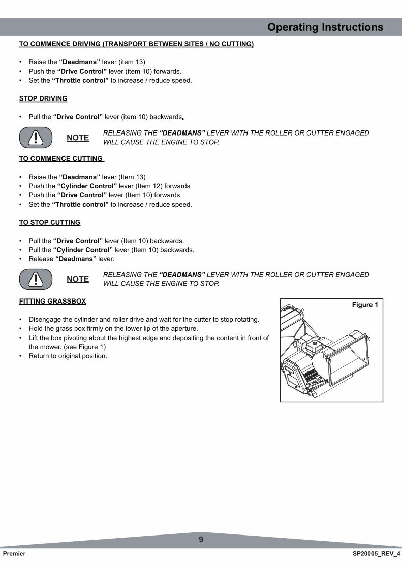
FITTING GRASSBOX
• Disengagethecylinderandrollerdriveandwaitforthecuttertostoprotating.• Holdthegrassboxfirmlyonthelowerlipoftheaperture.• Lifttheboxpivotingaboutthehighestedgeanddepositingthecontentinfrontof the mower. (see Figure 1)• Returntooriginalposition.
TO COMMENCE CUTTING
• Raisethe“Deadmans” lever (Item 13)• Pushthe“Cylinder Control” lever (Item 12) forwards • Pushthe“Drive Control” lever (Item 10) forwards • Setthe“Throttle control” to increase / reduce speed.
TO STOP CUTTING
• Pullthe“Drive Control” lever (Item 10) backwards.• Pullthe“Cylinder Control” lever (Item 10) backwards.• Release“Deadmans” lever.
RELEASING THE “DEADMANS” LEVER WITH THE ROLLER OR CUTTER ENGAGED WILL CAUSE THE ENGINE TO STOP.NOTE
Figure 1
10Premier SP20005_REV_4
As an indication coins measure the following:- - 1p 1.58mm (0.063” ) - 2p 1.80mm (0.071” ) - 5p 1.73mm (0.067” ) - 10p 1.84mm (0.072” ) - 50p 1.84mm (0.072” ) - £1.00 3.14mm (0.124” )
Remember height of cut is effected by moisture of turf , weight of machine and the thatch density. Different makes of machine cut at different heights when set to the same position with the setting bar. We suggest you set it to a couple of mm above your planned height and then come down in height by trial.
Ifonsettingtheheightofoperationyoufinditneedsalteringonceonthegreensimplyclick the adjusters up or down the same on each side until the desired height ofoperation is achieved.
Always check height of cut/operation with the setting bar provided. Check in twopositions i.e. one at either end of the cassette. Failure to do this could result in anuneven cut.
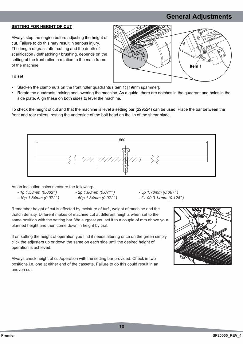
General AdjustmentsSETTING FOR HEIGHT OF CUT
Always stop the engine before adjusting the height ofcut. Failure to do this may result in serious injury.The length of grass after cutting and the depth ofscarification/dethatching/brushing,dependsonthesetting of the front roller in relation to the main frameof the machine.
To set:
• Slackentheclampnutsonthefrontrollerquadrants(Item1)[19mmspammer].• Rotatethequadrants,raisingandloweringthemachine.Asaguide,therearenotchesinthequadrantandholesinthe side plate. Align these on both sides to level the machine.
To check the height of cut and that the machine is level a setting bar (229524) can be used. Place the bar between the front and rear rollers, resting the underside of the bolt head on the lip of the shear blade.
560
Item 1
11Premier SP20005_REV_4
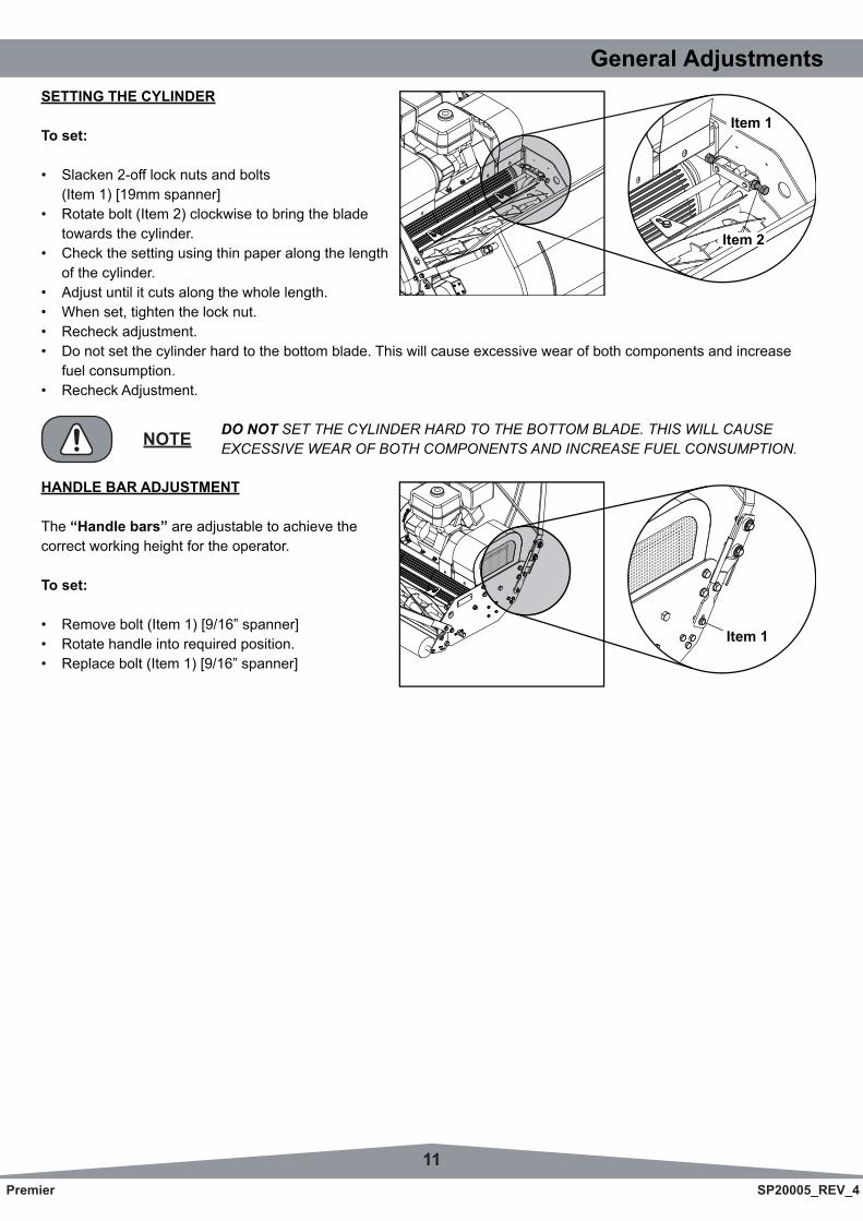
General AdjustmentsSETTING THE CYLINDER
To set:
• Slacken2-offlocknutsandbolts (Item1)[19mmspanner]• Rotatebolt(Item2)clockwisetobringtheblade towards the cylinder.• Checkthesettingusingthinpaperalongthelength of the cylinder.• Adjustuntilitcutsalongthewholelength.• Whenset,tightenthelocknut.• Recheckadjustment.• Donotsetthecylinderhardtothebottomblade.Thiswillcauseexcessivewearofbothcomponentsandincrease fuel consumption.• RecheckAdjustment.
Item 1
Item 2
DO NOT SET THE CYLINDER HARD TO THE BOTTOM BLADE. THIS WILL CAUSEEXCESSIVE WEAR OF BOTH COMPONENTS AND INCREASE FUEL CONSUMPTION.NOTE
HANDLE BAR ADJUSTMENT
The “Handle bars” are adjustable to achieve thecorrect working height for the operator.
To set:
• Removebolt(Item1)[9/16”spanner]• Rotatehandleintorequiredposition.• Replacebolt(Item1)[9/16”spanner]
Item 1
12Premier SP20005_REV_4
Routine Maintenance
OIL / FUEL TYPE & QUANTITY - SPARK PLUG TYPE
Engine Model Oil Type Quantity(Ltr) Fuel Type Capacity
(Ltr) Spark Plug Type Electrode Gap(mm)
Honda GX340 Petrol SAE 10W-40 1.1 Unleaded 6 BM6ES or BPR6ES 0.7 - 0.8Kubota OC60 Diesel SAE 30 1.0 Diesel 3.6 N/A N/A
Area Maintenance First 4 Hours First Month / 20 Hours 3 Months / 50 Hours 6 Months / 100 HoursEngine Oil Check Level üEngine Oil Change ü ü
Air Filter Check Condition / Clean ü ü
Spark Plug Change ü
ENGINE
Honda GX340 Petrol Engine. Forfullspecificationspleaserefertothemanufacturersinstructionmanualincluded.
No. Item Daily Initial 25Hr
Every 100Hr
Every 500Hr
Every 800Hr
Every 1500Hr
Every Year
Every 2 Years
Refer- ence Pge
1 Engine OilChecking Changing
ü
ü
üG-6 G-7
2 Oil Strainer Cleaning ü ü G-7
3 Rubber Hoses & Clamp Bands
Checking Changing
ü
üG-6
G-10
4 Air CleanerCleaning Changing
ü G-8G-10
5 Fuel FilterCleaning Changing
ü
üG-8 G-8
6 Valve Clearance Checking ü G-9
7 Nozzle injection pressure and spraying condition
Checking Changing
ü
üG-9, 10 G-9, 10
Kubota OC60 Diesel Engine. Forfullspecificationspleaserefertothemanufacturersinstructionmanualincluded.
Once a year or after 6 cleanings
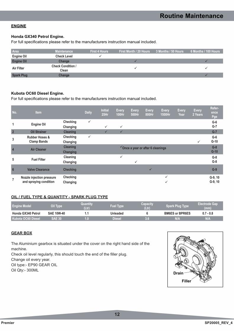
GEAR BOX
The Aluminium gearbox is situated under the cover on the right hand side of themachine.Checkoillevelregularly,thisshouldtouchtheendofthefillerplug.Change oil every year.Oil type:- EP90 GEAR OILOil Qty:- 300ML
Drain
Filler
13Premier SP20005_REV_4
Routine Maintenance
StorageThe machine should always be kept in a clean dry place, free from condensation. After use ensure that the machine is thoroughly clean, dry and free from grass and mud. Before off season storage smear a thin layer of grease on to thecutter blades and the shear blade.
Under no circumstances must the machine be steam cleaned as this may remove grease from the pre packed bearings.
Because of the nature of lead free petrol we recomend that if the machine is being left unused for more than 2 weeks the carburetor is run dry. Allow the engine to run out of fuel with the fuel tap switched off.
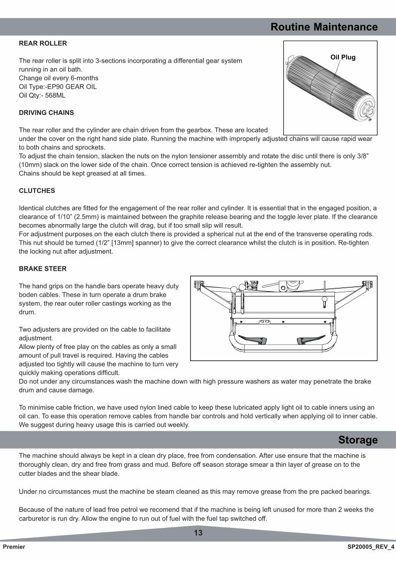
REAR ROLLER
The rear roller is split into 3-sections incorporating a differential gear systemrunning in an oil bath.Change oil every 6-monthsOil Type:-EP90 GEAR OILOil Qty:- 568ML
DRIVING CHAINS
The rear roller and the cylinder are chain driven from the gearbox. These are locatedunder the cover on the right hand side plate. Running the machine with improperly adjusted chains will cause rapid wear to both chains and sprockets.To adjust the chain tension, slacken the nuts on the nylon tensioner assembly and rotate the disc until there is only 3/8” (10mm) slack on the lower side of the chain. Once correct tension is achieved re-tighten the assembly nut.Chains should be kept greased at all times.
CLUTCHES
Identicalclutchesarefittedfortheengagementoftherearrollerandcylinder.Itisessentialthatintheengagedposition,aclearance of 1/10” (2.5mm) is maintained between the graphite release bearing and the toggle lever plate. If the clearance becomes abnormally large the clutch will drag, but if too small slip will result.For adjustment purposes on the each clutch there is provided a spherical nut at the end of the transverse operating rods. Thisnutshouldbeturned(1/2”[13mm]spanner)togivethecorrectclearancewhilsttheclutchisinposition.Re-tightenthe locking nut after adjustment.
BRAKE STEER
The hand grips on the handle bars operate heavy duty boden cables. These in turn operate a drum brakesystem, the rear outer roller castings working as the drum.
Two adjusters are provided on the cable to facilitate adjustment.Allow plenty of free play on the cables as only a small amount of pull travel is required. Having the cables adjusted too tightly will cause the machine to turn very quicklymakingoperationsdifficult.Do not under any circumstances wash the machine down with high pressure washers as water may penetrate the brake drum and cause damage.
To minimise cable friction, we have used nylon lined cable to keep these lubricated apply light oil to cable inners using an oil can. To ease this operation remove cables from handle bar controls and hold vertically when applying oil to inner cable. We suggest during heavy usage this is carried out weekly.
Oil Plug
14Premier SP20005_REV_4
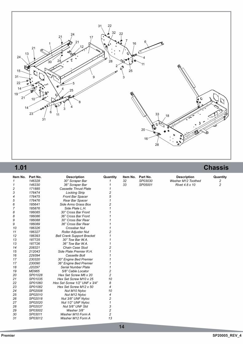
Item No. Part No. Description Quantity1 146328 30” Scraper Bar 11 146330 36” Scraper Bar 12 171885 Cassette Thrust Plate 13 176474 Locking Strip 24 176475 Front Bar Spacer 55 176476 Rear Bar Spacer 16 185641 Side Arms Grass Box 27 185876 Side Plate L.H. 18 186085 30” Cross Bar Front 18 186086 36” Cross Bar Front 19 186088 30” Cross Bar Rear 19 186089 36” Cross Bar Rear 110 186326 Crossbar Nut 111 186327 Roller Adjuster Nut 212 186393 Bell Crank Support Bracket 113 187725 30” Tow Bar W.A. 113 187726 36” Tow Bar W.A. 114 208321 Chain Case Stud 215 212043 Side Plate Premier R.H. 116 229394 Cassette Bolt 117 230320 30” Engine Bed Premier 117 230090 36” Engine Bed Premier 118 J20297 Serial Number Plate 119 MD965 5/8” Cable Locator 220 SP01028 Hex Set Screw M6 x 20 221 SP01035 Hex Set Screw M10 x 25 1022 SP01060 Hex Set Screw 1/2” UNF x 3/4” 823 SP01082 Hex Set Screw M12 x 50 424 SP02008 Nut M10 Nyloc 1025 SP02010 Nut M12 Nyloc 426 SP02018 Nut 3/8” UNF Nyloc 227 SP02020 Nut 1/2” UNF Nyloc 128 SP02037 Nut 5/8” UNF Std 329 SP03002 Washer 3/8” 230 SP03011 Washer M10 Form A 231 SP03012 Washer M12 Form A 13
1.01 ChassisItem No. Part No. Description Quantity32 SP03030 Washer M12 Toothed 233 SP05001 Rivet 4.8 x 10 2
21
21
2430
2421
1
843
116
31
23
254
9
5
14
10211914
22
31
15
2413
11
25
3
6167
2232
2231
17
12
228
4
20
1833
28
16
15Premier SP20005_REV_4
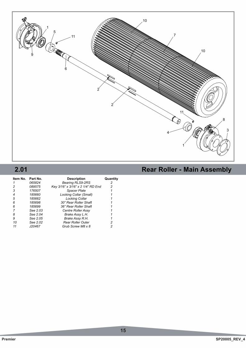
2.01 Rear Roller - Main AssemblyItem No. Part No. Description Quantity1 065824 Bearing RLS9-2RS 22 089575 Key 3/16” x 3/16” x 2 1/4” RD End 23 176507 Spacer Plate 14 185660 Locking Collar (Small) 15 185662 Locking Collar 16 185698 30” Rear Roller Shaft 16 185699 36” Rear Roller Shaft 17 See 2.03 Centre Roller Assy 18 See 2.04 Brake Assy L.H. 19 See 2.05 Brake Assy R.H. 110 See 2.02 Rear Roller Outer 211 J20467 Grub Screw M8 x 8 2
1
6
9
115
2
2
7
10
10
3
8
1
11
4
16Premier SP20005_REV_4
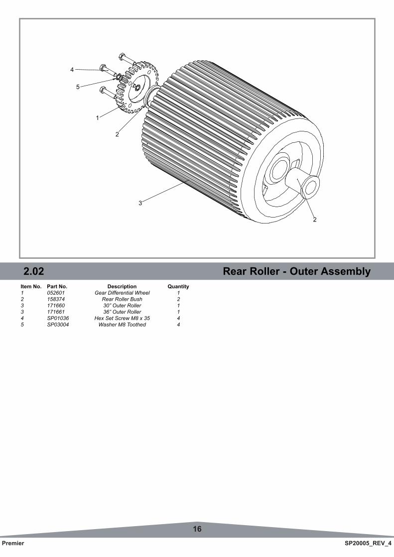
2.02 Rear Roller - Outer AssemblyItem No. Part No. Description Quantity1 052601 Gear Differential Wheel 12 158374 Rear Roller Bush 23 171660 30” Outer Roller 13 171661 36” Outer Roller 14 SP01036 Hex Set Screw M8 x 35 45 SP03004 Washer M8 Toothed 4
4
3
2
1
5
2
17Premier SP20005_REV_4
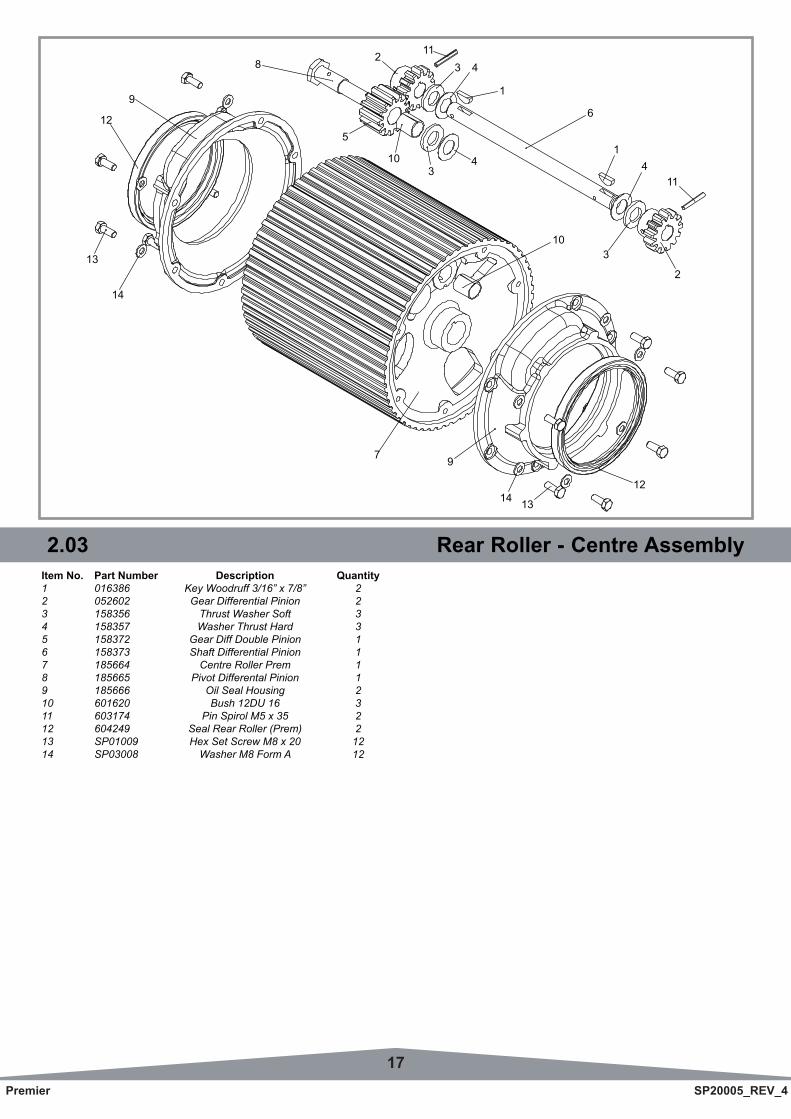
2.03 Rear Roller - Centre AssemblyItem No. Part Number Description Quantity1 016386 Key Woodruff 3/16” x 7/8” 22 052602 Gear Differential Pinion 23 158356 Thrust Washer Soft 34 158357 Washer Thrust Hard 35 158372 Gear Diff Double Pinion 16 158373 Shaft Differential Pinion 17 185664 Centre Roller Prem 18 185665 Pivot Differental Pinion 19 185666 Oil Seal Housing 210 601620 Bush 12DU 16 311 603174 Pin Spirol M5 x 35 212 604249 Seal Rear Roller (Prem) 213 SP01009 Hex Set Screw M8 x 20 1214 SP03008 Washer M8 Form A 12
11
103
4
1
43
5
6
2
2
3
411
1
10
14 13
12
7 9
9
12
13
14
8
18Premier SP20005_REV_4
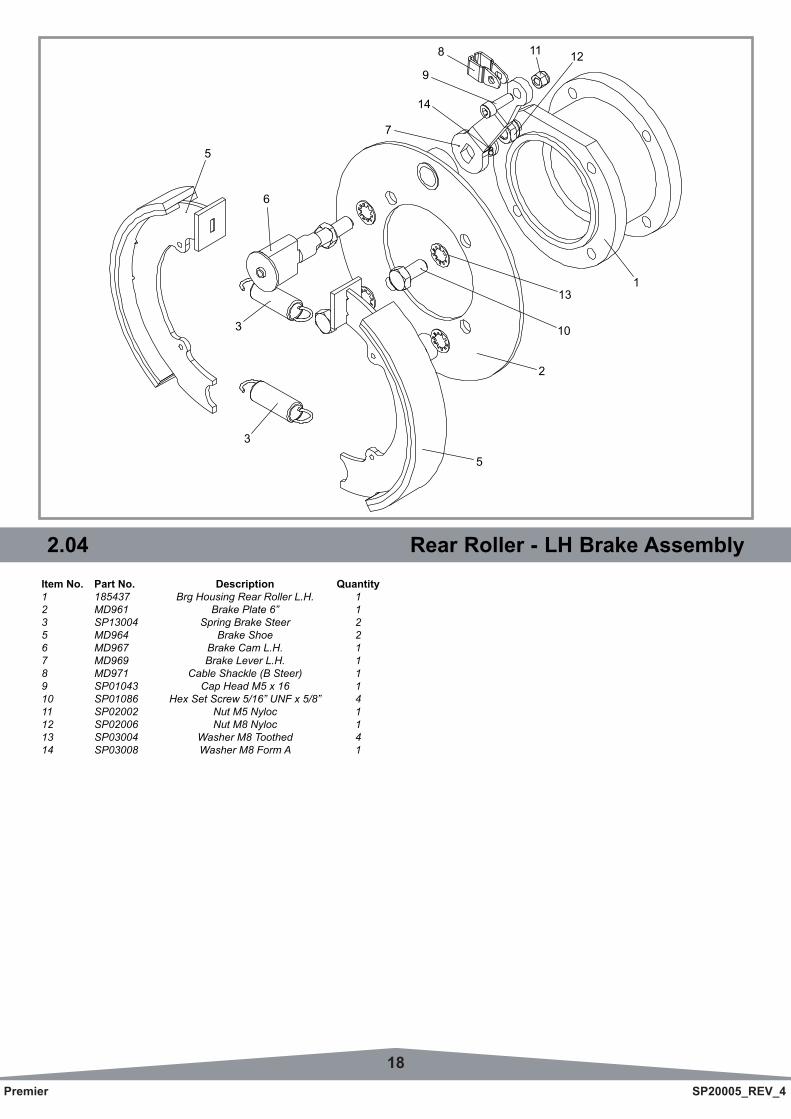
2.04 Rear Roller - LH Brake AssemblyItem No. Part No. Description Quantity1 185437 Brg Housing Rear Roller L.H. 12 MD961 Brake Plate 6” 13 SP13004 Spring Brake Steer 25 MD964 Brake Shoe 26 MD967 Brake Cam L.H. 17 MD969 Brake Lever L.H. 18 MD971 Cable Shackle (B Steer) 19 SP01043 Cap Head M5 x 16 110 SP01086 Hex Set Screw 5/16” UNF x 5/8” 411 SP02002 Nut M5 Nyloc 112 SP02006 Nut M8 Nyloc 113 SP03004 Washer M8 Toothed 414 SP03008 Washer M8 Form A 1
8
8
2
10
131
1211
7
14
9
5
3
3
6
5
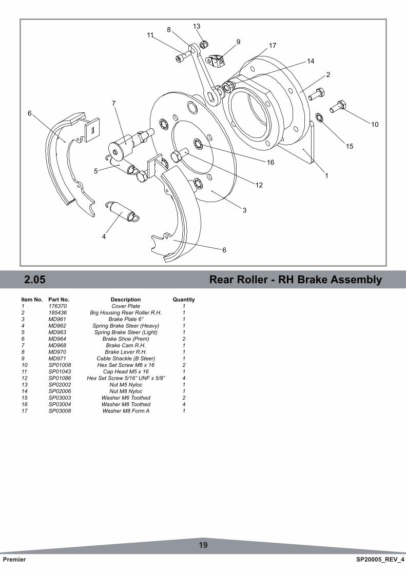
19Premier SP20005_REV_4
2.05 Rear Roller - RH Brake AssemblyItem No. Part No. Description Quantity1 176370 Cover Plate 12 185436 Brg Housing Rear Roller R.H. 13 MD961 Brake Plate 6” 14 MD962 Spring Brake Steer (Heavy) 15 MD963 Spring Brake Steer (Light) 16 MD964 Brake Shoe (Prem) 27 MD968 Brake Cam R.H. 18 MD970 Brake Lever R.H. 19 MD971 Cable Shackle (B Steer) 110 SP01008 Hex Set Screw M6 x 16 211 SP01043 Cap Head M5 x 16 112 SP01086 Hex Set Screw 5/16” UNF x 5/8” 413 SP02002 Nut M5 Nyloc 114 SP02006 Nut M8 Nyloc 115 SP03003 Washer M6 Toothed 216 SP03004 Washer M8 Toothed 417 SP03008 Washer M8 Form A 1
11
3
12
16
1
15
10
2
14
179
138
4
6
6
5
7
20Premier SP20005_REV_4
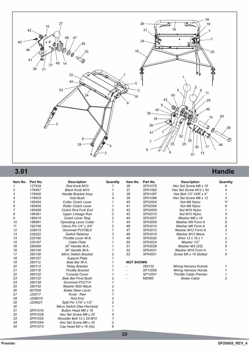
3.01 HandleItem No. Part No. Description Quantity1 127434 Red Knob M10 12 176457 Black Knob M10 13 178400 Handle Bracket Assy 24 178403 Void Bush 45 185454 Cutter Clutch Lever 16 185455 Roller Clutch Lever 17 185458 Clutch Rod Fork End 28 186391 Upper Linkage Rod 29 186415 Clutch Lever Stop 210 186981 Operating Lever Collar 111 192749 Clevis Pin 1/4” x 3/4” 212 228015 Grommet PV37BLK 113 229222 Switch Retainer 314 230190 Throttle Lever W.A. 115 230197 Cable Plate 116 260099 30” Handle W.A. 116 260100 36” Handle W.A. 117 260106 Micro Switch Bracket 218 260107 Support Plate 119 260112 Bale Bar W.A. 120 260113 Relay Bracket 121 260118 Throttle Bracket 122 260120 Console Cover 123 260122 Bale Bar Pivot Bush 224 260139 Grommet PV271A 125 260142 Washer M20 Wave 226 607509 Brake Steer Lever 227 J20017 Knob - Red 128 J209019 Rod End 229 J209021 Split Pin 1/16” x 1/2” 230 - Micro Switch [See Harness] 131 SP01019 Button Head M6 x 16 132 SP01028 Hex Set Screw M6 x 20 433 SP01029 Shoulder Bolt 12 x 25 M10 134 SP01054 Hex Set Screw M6 x 35 235 SP01073 Cap Head M3 x 16 (Ss) 6
Item No. Part No. Description Quantity36 SP01076 Hex Set Screw M8 x 16 637 SP01082 Hex Set Screw M12 x 50 438 SP01087 Hex Bolt 1/2” UNF x 4” 139 SP01088 Hex Set Screw M6 x 12 440 SP02004 Nut M6 Nyloc 1141 SP02006 Nut M8 Nyloc 642 SP02008 Nut M10 Nyloc 143 SP02010 Nut M12 Nyloc 544 SP03007 Washer M6 x 18 245 SP03009 Washer M5 Form A 646 SP03010 Washer M6 Form A 847 SP03012 Washer M12 Form A 348 SP03019 Washer M12 Wave 149 SP03020 Shim 12 x 18 x 1 250 SP03024 Washer 1/2” 251 SP03028 Washer M3 (SS) 652 SP03031 Washer M18 Form A 153 SP04001 Screw M5 x 16 Slotted 6
NOT SHOWN- 260132 Wiring Harness Kubota 1- SP12009 Wiring Harness Honda 1- SP12001 Throttle Cable Premier 1- MD960 Brake Cable 2
4748
27
42
40
46
41
36 2131 49 14
33
49
15
53
45
22
24
4
38
288
3
19
2
5
1
6
26
16
24
21 1626 18
7
20
7
25
88
7
741
36
1839
40943
505
1
46
10 50
38
46*
17
13
30
51
3525
52
11
29
26
21Premier SP20005_REV_4
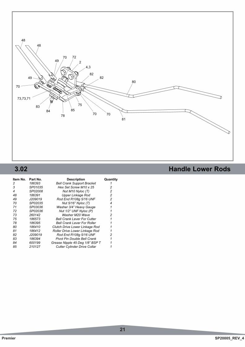
3.02 Handle Lower RodsItem No. Part No. Description Quantity2 186393 Bell Crank Support Bracket 13 SP01035 Hex Set Screw M10 x 25 24 SP02008 Nut M10 Nyloc (T) 248 186391 Upper Linkage Rod 249 J209019 Rod End R108g 5/16 UNF 270 SP02035 Nut 5/16” Nyloc (T) 471 SP03036 Washer 3/4” Heavy Gauge 172 SP02036 Nut 1/2” UNF Nyloc (P) 173 260142 Washer M20 Wave 275 186573 Bell Crank Lever For Cutter 178 186395 Bell Crank Lever For Roller 180 186410 Clutch Drive Lower Linkage Rod 181 186412 Roller Drive Lower Linkage Rod 182 J209019 Rod End R108g 5/16 UNF 283 186394 Pivot Pin Double Bell Crank 184 600199 Grease Nipple 45 Deg 1/8” BSP T 185 210127 Cutter Cylinder Drive Collar 1
8483
78
73,73,71
70
49
48
4970
75
82
70
82
70
80
81
4,32
85
72
48
22Premier SP20005_REV_4
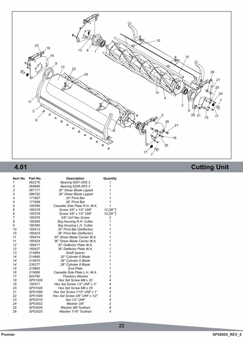
4.01 Cutting UnitItem No. Part No. Description Quantity1 062276 Bearing 6207-2RS 3 12 065696 Bearing 6206-2RS 3 13 067171 30” Shear Blade Lipped 13 086792 36” Shear Blade Lipped 14 171697 30” Pivot Bar 14 171698 36” Pivot Bar 15 185369 Cassette Side Plate R.H. W.A. 16 185378 Screw 3/8” x 1/2” UNF 12 [36””] 6 185378 Screw 3/8” x 1/2” UNF 10 [30””]7 185379 5/8” Unf Hex Screw 28 185384 Brg Housing R.H. Cutter 19 185385 Brg Housing L.H. Cutter 110 185413 30”PivotBar(Deflector) 110 185423 36”PivotBar(Deflector) 111 185414 30” Shear Blade Carrier W.A. 111 185424 36” Shear Blade Carrier W.A. 112 185417 30”DeflectorPlateW.A. 112 185427 36”DeflectorPlateW.A. 113 214964 Shaft Spacer 114 214969 30” Cylinder 6 Blade 114 214970 36” Cylinder 6 Blade 114 230277 36” Cylinder 8 Blade 115 219665 End Plate 116 219666 Cassette Side Plate L.H. W.A. 117 604760 Thackery Washer 218 SP01009 Hex Set Screw M8 x 20 419 185371 Hex Set Screw 1/2” UNF x 3” 420 SP01045 Hex Set Screw M8 x 25 421 SP01089 Hex Set Screw 7/16” UNF x 1” 422 SP01090 Hex Set Screw 3/8” UNF x 1/2” 223 SP02016 Nut 1/2” UNF 424 SP03002 Washer 3/8” 225 SP03004 Washer M8 Toothed 826 SP03025 Washer 7/16” Toothed 4
8
21
25
20
7
171521269
2
414
10
10
13 1
26
10
717
25
18
2126
5
2319
16
9
11
3
6
12 2224
23Premier SP20005_REV_4
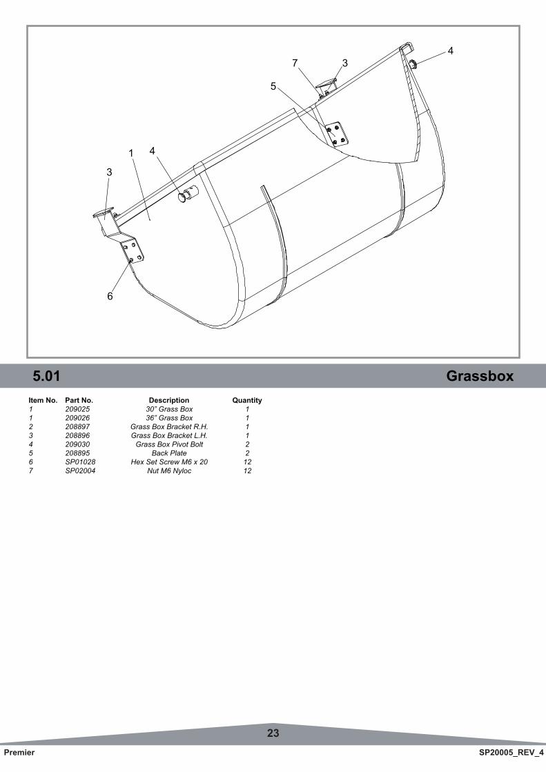
4.01 Cutting Unit 5.01 GrassboxItem No. Part No. Description Quantity1 209025 30” Grass Box 11 209026 36” Grass Box 12 208897 Grass Box Bracket R.H. 13 208896 Grass Box Bracket L.H. 14 209030 Grass Box Pivot Bolt 25 208895 Back Plate 26 SP01028 Hex Set Screw M6 x 20 127 SP02004 Nut M6 Nyloc 12
4
6
3
1
437
5
24Premier SP20005_REV_4
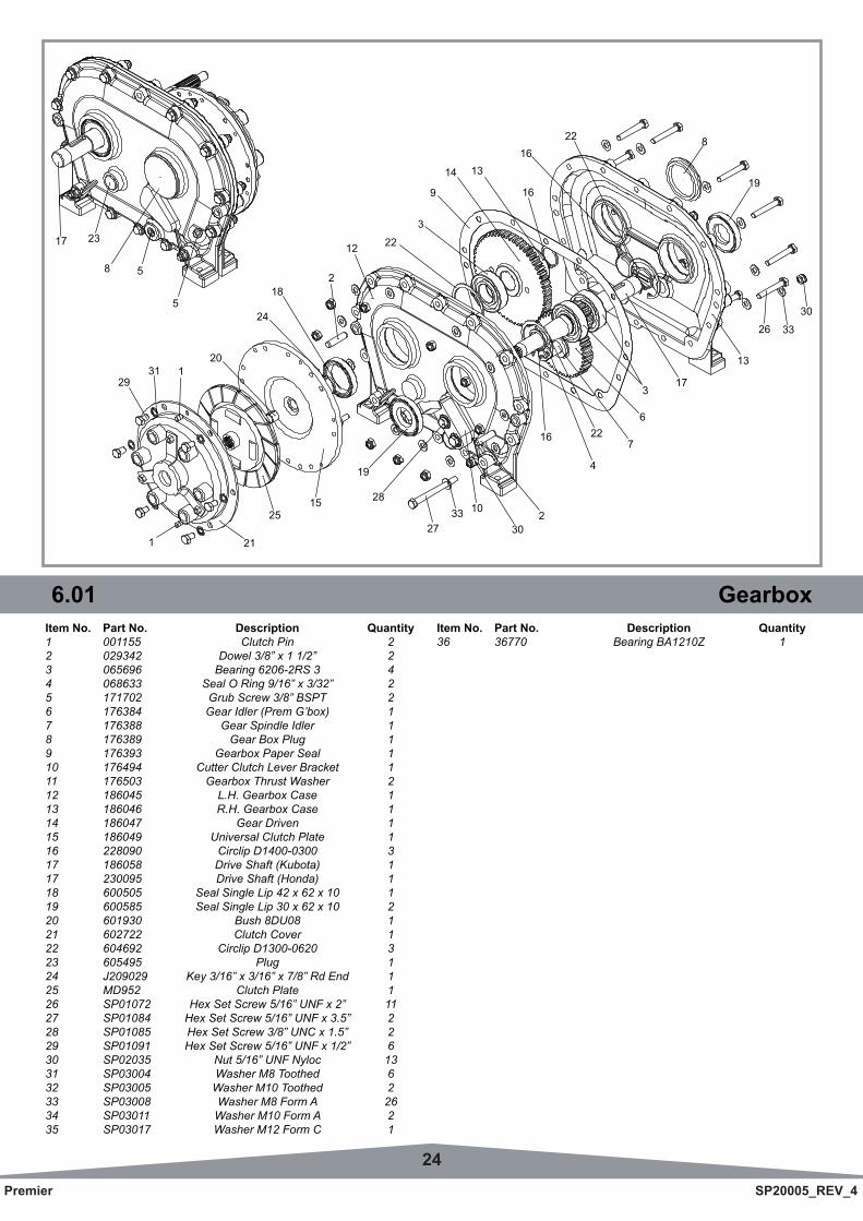
6.01 GearboxItem No. Part No. Description Quantity1 001155 Clutch Pin 22 029342 Dowel 3/8” x 1 1/2” 23 065696 Bearing 6206-2RS 3 44 068633 Seal O Ring 9/16” x 3/32” 25 171702 Grub Screw 3/8” BSPT 26 176384 Gear Idler (Prem G’box) 17 176388 Gear Spindle Idler 18 176389 Gear Box Plug 19 176393 Gearbox Paper Seal 110 176494 Cutter Clutch Lever Bracket 111 176503 Gearbox Thrust Washer 212 186045 L.H. Gearbox Case 113 186046 R.H. Gearbox Case 114 186047 Gear Driven 115 186049 Universal Clutch Plate 116 228090 Circlip D1400-0300 317 186058 Drive Shaft (Kubota) 117 230095 Drive Shaft (Honda) 118 600505 Seal Single Lip 42 x 62 x 10 119 600585 Seal Single Lip 30 x 62 x 10 220 601930 Bush 8DU08 121 602722 Clutch Cover 122 604692 Circlip D1300-0620 323 605495 Plug 124 J209029 Key 3/16” x 3/16” x 7/8” Rd End 125 MD952 Clutch Plate 126 SP01072 Hex Set Screw 5/16” UNF x 2” 1127 SP01084 Hex Set Screw 5/16” UNF x 3.5” 228 SP01085 Hex Set Screw 3/8” UNC x 1.5” 229 SP01091 Hex Set Screw 5/16” UNF x 1/2” 630 SP02035 Nut 5/16” UNF Nyloc 1331 SP03004 Washer M8 Toothed 632 SP03005 Washer M10 Toothed 233 SP03008 Washer M8 Form A 2634 SP03011 Washer M10 Form A 235 SP03017 Washer M12 Form C 1
Item No. Part No. Description Quantity36 36770 Bearing BA1210Z 1
14
27
28
19
21
1525
1
2931 1
20
17 23
8 5
524
18
16
2
12 22
13
9
13
173
722
4
6
16
230
1033
22 8
19
26 33
30
16
3
25Premier SP20005_REV_4
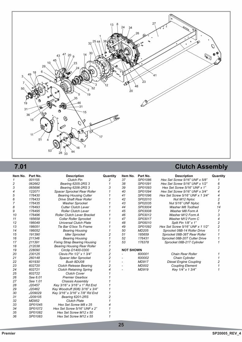
6.01 Gearbox 7.01 Clutch AssemblyItem No. Part No. Description Quantity1 001155 Clutch Pin 22 062662 Bearing 6205-2RS 3 13 065696 Bearing 6206-2RS 3 34 122071 Spacer Sprocket Rear Roller 15 176430 Bearing Housing Cutter 16 176433 Drive Shaft Rear Roller 17 176435 Washer Sprocket 18 176493 Cutter Clutch Lever 19 176495 Roller Clutch Lever 110 176496 Roller Clutch Lever Bracket 111 185658 Collar Roller Sprocket 112 186049 Universal Clutch Plate 113 186051 Tie Bar G’box To Frame 114 186052 Bearing Housing 115 191390 Idler Sprocket 216 211346 Bearing Housing 117 211391 Fixing Strap Bearing Housing 218 212038 Bearing Housing Rear Roller 119 228090 Circlip D1400-0300 220 230125 Clevis Pin 1/2” x 1 3/4” 221 260148 Spacer Idler Sprocket 222 601930 Bush 8DU08 123 602720 Clutch Release Bearing 224 602721 Clutch Retaining Spring 425 602722 Clutch Cover 126 See 6.01 Premier Gearbox 127 See 1.01 Chassis Assembly 128 J20457 Key 3/16” x 3/16” x 1” Rd End 129 J20462 Key Woodruff (606) 3/16” x 3/4” 130 J209029 Key 3/16” x 3/16” x 7/8” Rd End 131 J209105 Bearing 6201-2RS 232 MD952 Clutch Plate 133 SP01045 Hex Set Screw M8 x 25 434 SP01072 Hex Set Screw 5/16” UNF x 2” 135 SP01082 Hex Set Screw M12 x 50 136 SP01083 Hex Set Screw M12 x 55 1
Item No. Part No. Description Quantity37 SP01086 Hex Set Screw 5/16” UNF x 5/8” 138 SP01091 Hex Set Screw 5/16” UNF x 1/2” 639 SP01093 Hex Set Screw 5/16” UNF x 1” 240 SP01094 Hex Set Screw 5/16” UNF x 3/4” 441 SP01096 Hex Set Screw 5/16” UNF x 1 3/4” 442 SP02010 Nut M12 Nyloc 243 SP02035 Nut 5/16” UNF Nyloc 844 SP03004 Washer M8 Toothed 1445 SP03008 Washer M8 Form A 746 SP03012 Washer M12 Form A 347 SP03017 Washer M12 Form C 448 SP05010 Split Pin 1/8” x 1” 249 SP01092 Hex Set Screw 5/16” UNF x 1 1/2” 250 MD205 Sprocket 08B-14 Roller Drive 151 185659 Sprocket 08B-38T Rear Roller 152 176431 Sprocket 08B-20T Cutter Drive 153 176378 Sprocket 08B-21T Cylinder 1
NOT SHOWN- 600001 Chain Rear Roller 1- 600002 Chain Cylinder 1- MD917 Diesel Engine Coupling 2- MD002 Coupling Element 1- MD919 Key 1/4” x 1 3/4” 1
6
3146
35
3014
2423
920
18
1536
31
19
50
7
3 49
474345
1029
32
41
2348
20
12
5 193 52
3
1644
332853
45111
2
17
15
1384425
13 824 34
26
27
26Premier SP20005_REV_4
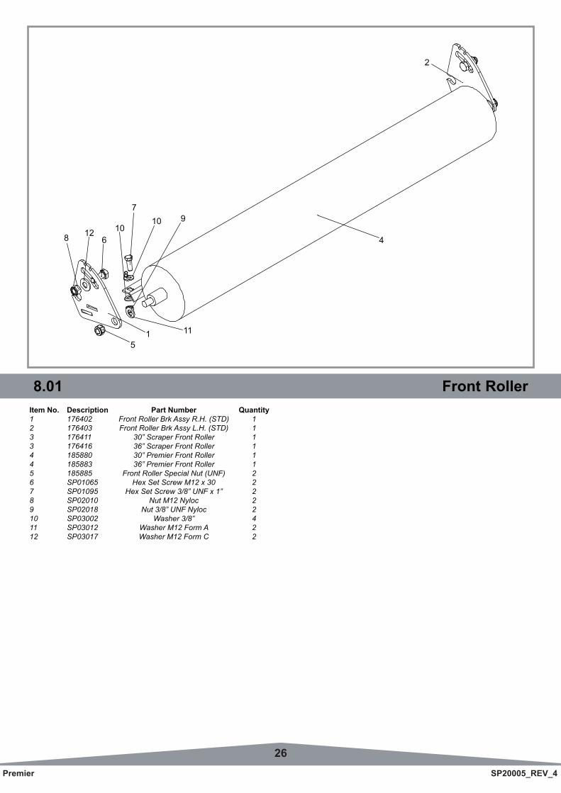
8.01 Front RollerItem No. Description Part Number Quantity1 176402 Front Roller Brk Assy R.H. (STD) 12 176403 Front Roller Brk Assy L.H. (STD) 13 176411 30” Scraper Front Roller 13 176416 36” Scraper Front Roller 14 185880 30” Premier Front Roller 14 185883 36” Premier Front Roller 15 185885 Front Roller Special Nut (UNF) 26 SP01065 Hex Set Screw M12 x 30 27 SP01095 Hex Set Screw 3/8” UNF x 1” 28 SP02010 Nut M12 Nyloc 29 SP02018 Nut 3/8” UNF Nyloc 210 SP03002 Washer 3/8” 411 SP03012 Washer M12 Form A 212 SP03017 Washer M12 Form C 2
8
88
51 11
9107
106
124
2
27Premier SP20005_REV_4
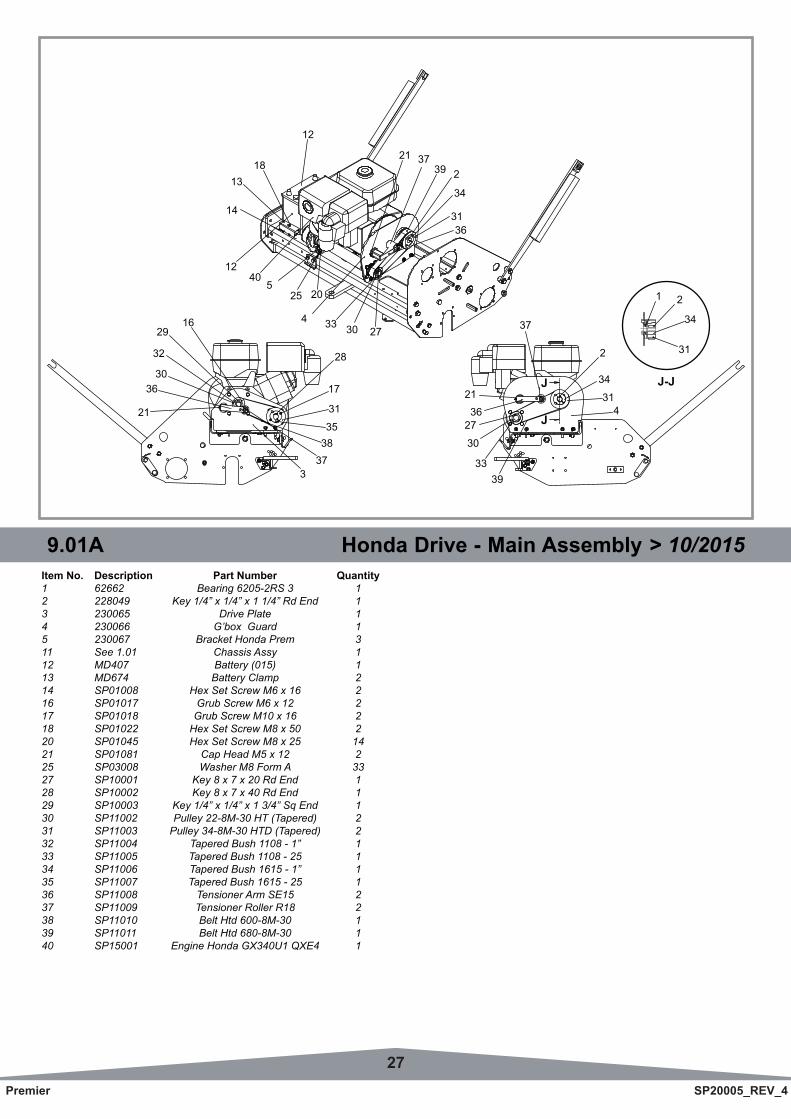
8.01 Front Roller 9.01A Honda Drive - Main Assembly > 10/2015Item No. Description Part Number Quantity1 62662 Bearing 6205-2RS 3 12 228049 Key 1/4” x 1/4” x 1 1/4” Rd End 13 230065 Drive Plate 14 230066 G’box Guard 15 230067 Bracket Honda Prem 311 See 1.01 Chassis Assy 112 MD407 Battery (015) 113 MD674 Battery Clamp 214 SP01008 Hex Set Screw M6 x 16 216 SP01017 Grub Screw M6 x 12 217 SP01018 Grub Screw M10 x 16 218 SP01022 Hex Set Screw M8 x 50 220 SP01045 Hex Set Screw M8 x 25 1421 SP01081 Cap Head M5 x 12 225 SP03008 Washer M8 Form A 3327 SP10001 Key 8 x 7 x 20 Rd End 128 SP10002 Key 8 x 7 x 40 Rd End 129 SP10003 Key 1/4” x 1/4” x 1 3/4” Sq End 130 SP11002 Pulley 22-8M-30 HT (Tapered) 231 SP11003 Pulley 34-8M-30 HTD (Tapered) 232 SP11004 Tapered Bush 1108 - 1” 133 SP11005 Tapered Bush 1108 - 25 134 SP11006 Tapered Bush 1615 - 1” 135 SP11007 Tapered Bush 1615 - 25 136 SP11008 Tensioner Arm SE15 237 SP11009 Tensioner Roller R18 238 SP11010 Belt Htd 600-8M-30 139 SP11011 Belt Htd 680-8M-30 140 SP15001 Engine Honda GX340U1 QXE4 1
1629
4 33 30 27
3373835
31
17
28
21
3630
21
37
239
34
37
3136
21
12
1318
14
32
1240
525 20
3933
30
2736
21
31
34
431
34
2
J-JJ
J
28Premier SP20005_REV_4
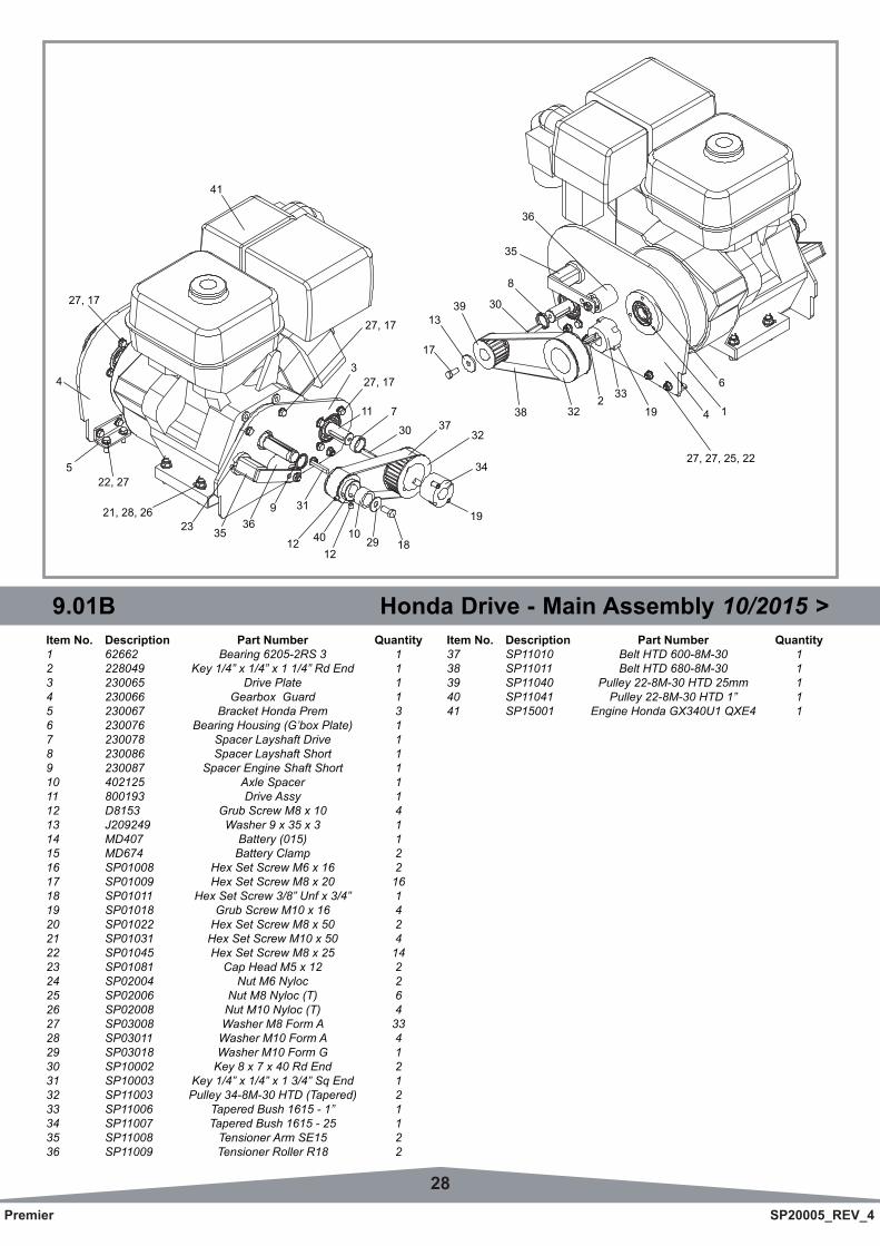
9.01B Honda Drive - Main Assembly 10/2015 >Item No. Description Part Number Quantity1 62662 Bearing 6205-2RS 3 12 228049 Key 1/4” x 1/4” x 1 1/4” Rd End 13 230065 Drive Plate 14 230066 Gearbox Guard 15 230067 Bracket Honda Prem 36 230076 Bearing Housing (G’box Plate) 17 230078 Spacer Layshaft Drive 18 230086 Spacer Layshaft Short 19 230087 Spacer Engine Shaft Short 110 402125 Axle Spacer 111 800193 Drive Assy 112 D8153 Grub Screw M8 x 10 413 J209249 Washer 9 x 35 x 3 114 MD407 Battery (015) 115 MD674 Battery Clamp 216 SP01008 Hex Set Screw M6 x 16 217 SP01009 Hex Set Screw M8 x 20 1618 SP01011 Hex Set Screw 3/8” Unf x 3/4” 119 SP01018 Grub Screw M10 x 16 420 SP01022 Hex Set Screw M8 x 50 221 SP01031 Hex Set Screw M10 x 50 422 SP01045 Hex Set Screw M8 x 25 1423 SP01081 Cap Head M5 x 12 224 SP02004 Nut M6 Nyloc 225 SP02006 Nut M8 Nyloc (T) 626 SP02008 Nut M10 Nyloc (T) 427 SP03008 Washer M8 Form A 3328 SP03011 Washer M10 Form A 429 SP03018 Washer M10 Form G 130 SP10002 Key 8 x 7 x 40 Rd End 231 SP10003 Key 1/4” x 1/4” x 1 3/4” Sq End 132 SP11003 Pulley 34-8M-30 HTD (Tapered) 233 SP11006 Tapered Bush 1615 - 1” 134 SP11007 Tapered Bush 1615 - 25 135 SP11008 Tensioner Arm SE15 236 SP11009 Tensioner Roller R18 2
Item No. Description Part Number Quantity37 SP11010 Belt HTD 600-8M-30 138 SP11011 Belt HTD 680-8M-30 139 SP11040 Pulley 22-8M-30 HTD 25mm 140 SP11041 Pulley 22-8M-30 HTD 1” 141 SP15001 Engine Honda GX340U1 QXE4 1
27, 17
27, 17
17
1339
38
8
2 3319
30
32
6
1
35
36
4
27, 27, 25, 22
19
34
3237
182910
1212 40
319
30
7
23 35
41
21, 28, 26
522, 27
43
11
36
27, 17
29Premier SP20005_REV_4
9.02 Kubota Drive - Main AssemblyItem No. Description Part Number Quantity
NOT SHOWN
- MD914 Engine Kubota OC60 (Diesel) 1- MD917 1” Diesel Engine Coupling 2- MD002 Coupling Element L110 1- 228049 “Key 1/4” x 1/4” x 1 1/4” Rd End Gearbox Shaft” 1- MD919 “Key 1/4” x 1/4” x 1 3/4” Rd End Engine Shaft” 1
9.01B Honda Drive - Main Assembly 10/2015 >
No Image Available
30Premier SP20005_REV_4
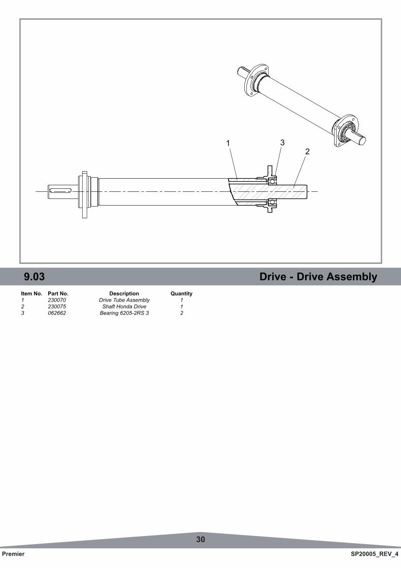
9.03 Drive - Drive AssemblyItem No. Part No. Description Quantity1 230070 Drive Tube Assembly 12 230075 Shaft Honda Drive 13 062662 Bearing 6205-2RS 3 2
12
3
31Premier SP20005_REV_4
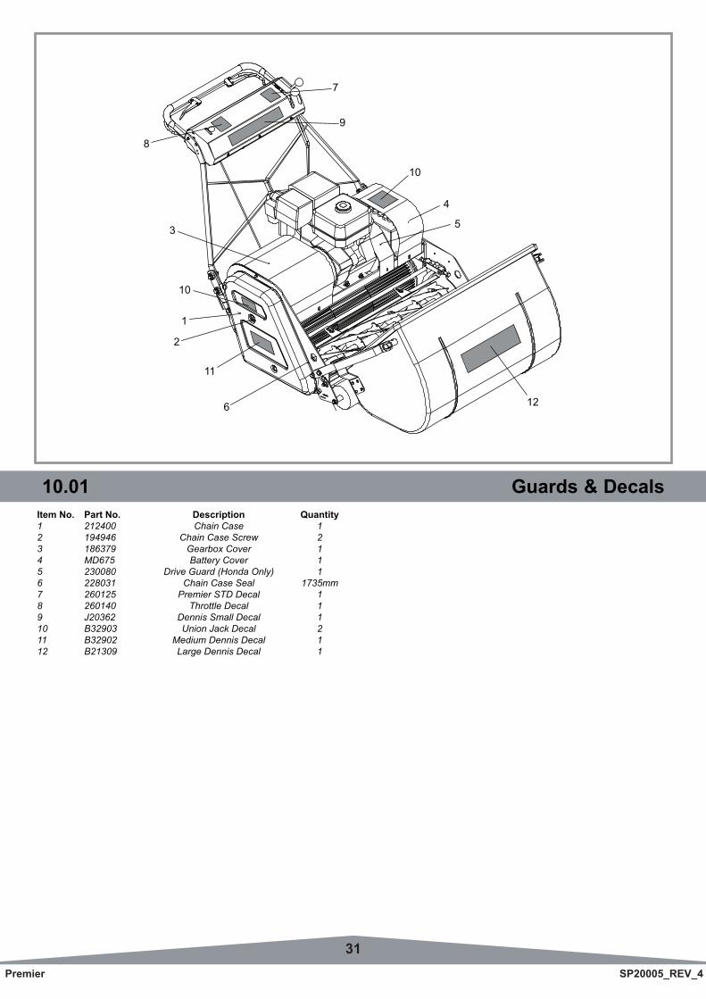
9.03 Drive - Drive Assembly 10.01 Guards & DecalsItem No. Part No. Description Quantity1 212400 Chain Case 12 194946 Chain Case Screw 23 186379 Gearbox Cover 14 MD675 Battery Cover 15 230080 Drive Guard (Honda Only) 16 228031 Chain Case Seal 1735mm7 260125 Premier STD Decal 18 260140 Throttle Decal 19 J20362 Dennis Small Decal 110 B32903 Union Jack Decal 211 B32902 Medium Dennis Decal 112 B21309 Large Dennis Decal 1
3
6
2
1
6
4
5
10
11
9
7
8
10
12

DENNIS, Ashbourne Road, Kirk Langley, Derby, DE6 4NJ, United KingdomTelephone:- 01332 824777
Fax:- 01332 824 525E-mail:- [email protected]
E-mail:- [email protected]
www.dennisuk.com