r brush-pro - sisis.com · b c 12 2 certificate of conformity brush-pro ride-on brush system...
TRANSCRIPT

BRUSH-PRORIDE-ON BRUSH SYSTEMINSTRUCTION MANUAL
R
SP20017_REV_012/12

BRUSH-PRO DEC ‘12
2
Certificate of ConformityBrush-Pro ride-on brush system powered by Honda GX Petrol Engine
Manufacturer:- Howardson Ltd, Howardson Works, Kirk Langley, Derby, DE6 4NJ. UK
Owner of Technical Document:- Mr I.D. Howard, Howardson Ltd, Howardson Works Kirk Langley, Derby, DE6 4NJ, UK
Notified Body:- AV Technology Ltd, AVTECH house, Arkle Avenue, Stanley Green Trading Estate, Handforth, Cheshire, SK9 3RW, UK
I the under signed Declare that these machines:-
Tested at:- Howardson Works test site September 2011
Complies with the applicable requirements of:- - Machine Directive 2006/42/EC - Noise Directive 2000/14/EC (Annex VI Procedure 1)
Managing Director
Ian Howard
The reliability and quality of performance of the BRUSH-PRO depends upon some simple care maintenance carried out regularly. This manual has been prepared to allow the user to carry out all such work.
It is advisable to read the instructions carefully. Proper care and attention will enable the machine to give a continuous, satisfactory, and reliable service. Failure to carry out regular lubrication and maintenance as outlined in this manual may render any guarantee or warranty invalid.
In the case of any difficulty, or if further information or advice is required, our Service Department is always at your call. In the interests of speed and accuracy of information please quote the serial numbers of the machine and engine whenmaking enquiries.
For the BRUSH-PRO, this is to be found on a plate attached to the side frame. The engine number is stamped on either the crank case or the gear casing facing towards the front of the machine. We suggest you write the numbers onthe front page of this book.
Introduction
Serial Numbers
MACHINE SERIAL NUMBER
MAKE A NOTE OF THE SERIAL NUMBERS OF YOUR MACHINE & ENGINE AND ALWAYS QUOTE THEM IN ANY COMMUNICATION WITH PERSONNEL AT DENNIS.NOTE
ENGINE SERIAL NUMBER
Certificate of Conformity

BRUSH-PRO DEC ‘12
3
Contents PageCertificate of Conformity ....................................................................................................................................................... 2Serial Numbers ..................................................................................................................................................................... 2Introduction ........................................................................................................................................................................... 2Technical Data ...................................................................................................................................................................... 3Machine Description ............................................................................................................................................................. 4Important Safety Instructions ................................................................................................................................................ 5Operating Instructions ..................................................................................................................................................... 6 - 7Parts Listings ................................................................................................................................................................. 8 - 13
Technical Data
Model Brush-ProA - Width (M) 1.5B - Length (M) 2.1C - Height (M) 1.1D - Width - Brushes Down (mm) 3.0Weight (Kg) 350Engine Honda GXV390 - 7.6kWDrive System Hydrostatic TransaxleMeasured Sound Power Level dB(A) LWA 91Guaranteed Sound Power Level dB(A) LWA 94
AB C
D

BRUSH-PRO DEC ‘12
4
Machine DescriptionThe SISIS Brush-Pro has been designed for use on artificial surfaces to re-distribute the infill and keep the infillmaterial from compacting and migrating, whilst also brushing/grooming the carpet pile. The Brush Pro is powered by a7.6 kW (10.2 Hp) air cooled 4-stroke single cylinder engine.
The Brush-Pro has 2 mid mounted oscillating brushes and a rear drag brush, both sets are lifted and lowered byelectrically operated rams and which also allow for any increase in ground clearance. The centre brushes oscillate to loosen the infill and the rear drag brushes follow to settle and finish the infill. The rear brushes have two wing/outerbrushes which are attached to gas springs to ensure constant and even pressure over the contact surface. The rear brushes are used daily to maintain the surface to redistribute the infill material and groom the synthetic surface.
1. Centre Brushes 7. Operator Seat2. Rear Brushes 8. Operator Controls3. Air Filter 9. Steering Column Release4. Fuel Tank 10. Axle Drive Engage Rod 5. Foot Pedal 11. Exhaust6. Steering Wheel
1
2
3
84
56
7
2
9
10
11
BRUSH-PRO DEC ‘12
5
Machine Description Important Safety InstructionsIn order to operate the machine safely please follow these Health and Safety guidelines.
TRAINING
READ THE INSTRUCTIONS CONTAINED IN THIS MANUAL WITH CARE. IF YOU ARE IN ANY DOUBT PLEASE ASK YOUR EMPLOYER OR CONTACT US DIRECT AT SISIS.CAUTION
• Be familiar with the controls and the proper use of the equipment.• Never allow children or people unfamiliar with these instructions to use the Brush-Pro. Local regulations or insurance may restrict the age of the operator.• Keep in mind that the operator or user is responsible for accidents or hazards occurring to other people or their property.
PREPARATION
PETROL IS HIGHLY FLAMMABLE AND WILL DAMAGE GRASS IF SPILT.WARNING
A) Store fuel in containers specifically designed for this purpose.B) Refuel out doors and do not refuel whilst smoking.C) Add fuel before starting the engine. Never remove the cap of the fuel tank or add petrol while the engine is running or when the engine is hot.D) If petrol is spilled do not attempt to start the engine but move the machine away from the area of spill and avoid creating any sources of ignition until the vapours have dissipated.
• Replace damaged or faulty silencers.• Before using the machine always inspect the safety devices including the cut off switch and the blades for excessive wear or damage. Replace if necessary.
OPERATION
• Do not operate the engine in a confined space where dangerous CARBON MONOXIDE fumes can collect.• Use extreme caution when reversing or pulling the machine towards you.

BRUSH-PRO DEC ‘12
6
Operating Instructions
OPERATING INSTRUCTIONS
Before operating the Brush-Pro ensure the drive enage lever is pushed in fully to disenagethe rear drive axle (See Figure 1). This allows safe starting of the motor whether the user isseated or standing at the side of the machine. The engine will not start if the operator isunseated with the drive engage lever in the enaged position, fully out. Check that the brake ison (See Figure 2) and that the centre and rear brushes (Item 1 & 2, Machine Description)are off the ground, see ‘Operating the Brushes’ and disenaged with the brush engage lever inthe off position.
The Honda GXV390 is equipped with electric key start or recoil start at the engine. Beforestarting the Brush-Pro ensure the drive engage lever (Item 10, Machine Description)is pushed in fully to disenage the rear drive axle. Once seated the drive engage levercan be pulled out fully to engage drive, this fully activates the foot pedal.
To start the engine from cold pull the throttle lever back to the choke position(See Figure 2), and turn the ignition key. Release the key once the engine has startedand allow the engine to warm up. To stop the engine turn the ignition switch to the offposition. Use the recoil start if the battery is not charged sufficiently to start the engine.
Once the engine is warm release the brake lever to the off position (See Figure 3) anddepress the Operator’s Pedal (Item 5, Machine Description).
The Brush-Pro is driven by a Hydrostatic Axle, with the axle engaged (lever fully out)pressing the top of the pedal gives forward motion and pressing the bottom of the pedalputs the Brush-Pro into reverse. Releasing the pedal stops the Brush-Pro. The drive isproportional to the travel of the pedal.
The engine will cutout if the pedal is pressed significantly without releasing the brakelever, thus protecting the rear axle brake.
OPERATING THE BRUSHES
The Brush-Pro is fitted with oscillating centrebrushes and a set of rear finishing brushes.The rear brushes have two outer wing brusheswhich can be lowered into place giving a widefinishing width and even ground pressure(See Figure 4). Both the centre and rearbrushes are height controlled via electric rams,with two rocker switches on the control panel,(See Figure 5). The centre brushes can also beused as drag brushes or by enaging drive in oscillating motion to aggrevate andredistribute the infill material.
To enage the oscillating motion pull the centre brush drive lever back to the on position,(See Figure 5). Both the mechanisms that control the brushes compensate for groundclearance allowing them to be fully lowered onto the ground. The engine will cutout ifthe centre brush drive is engaged with the brake lever in the on position, thus protectingthe centre brush oscillating mechanism.
BEFORE YOU OPERATE THIS MACHINE YOU MUST READ AND STUDY THIS MANUAL. IF YOU ARE IN ANY DOUBT PLEASE ASK YOUR EMPLOYER OR CONTACT US DIRECT.CAUTION
Figure 2
Figure 3
Figure 4
Figure 5
Figure 6

BRUSH-PRO DEC ‘12
7
Operating InstructionsTRANSPORT
Disengage the rear wheel drive by pushing in the drive engage lever fully in (See Figure 6).This allows the machine to be manoeuvred for transportation. When moving the machine byhand best practice is to hold the machine by the floor tubes, of if towing use the frontbumper tube.
MAINTENANCE Engine - Honda GXV390 7.6kW 10.2 HP Engine Oil - SAE 10w-40 Hydrostatic Axle Oil - SEA 10W-30 Tyre Pressures - Front 25 PSI, Rear 25 PSI Battery - 12 VDC Drive - Hydrostatic transaxle - rear axle Centre Brush Drive - Belt drive
Operating Instructions
CHECK TYRES ARE AT THE CORRECT PRESSURE, SEE ABOVE. CHECK ENGINE OIL LEVEL. CHECK BRUSHES FOR WEAR OR DAMAGE.NOTE
• For access to the battery remove the left side top cover by loosening the screws as shown (See Figure 7).• For access to the controls and tensioning cables remove the right side top cover (See Figure 8).• For access to the centre brush mechanism remove all side covers (See Figure 9).• For access to the machine drive mechanisms remove the front cover and seat plate (See Figure 9).
Figure 6
Figure 7 Figure 8 Figure 9
BELT TENSIONING
The Brush-Pro uses two tensioning cables for the engagement of the belt drive and rear hydrostatic axle brake. Remove the right side cover to get access to the tensioning nuts for tension adjustment (See Figure 8).

BRUSH-PRO DEC ‘12
8
Item No. Part No. Description Quantity1 228054 Spirol Pin (M8 x 50) 22 401206 Bearing Spacer 23 401229 Plate Actuator Link 24 401242 Brush Holder Assembly 15 401255 Angle Lift Plate WA 16 401257 Centre Brush Shaft 17 401301 Centre Brush Frame Assembly 18 401302 Brush Holder Assembly 19 401303 Spacer Rod End 110 401304 Crank Arm 111 401337 Boss Actuator 212 401338 Angle Lift Plate WA 113 401634 Pivot Arm Brush 214 401659 Spacer Bearing 415 BA1009 Bush Oilite Al1218 416 D8154 Grub Screw M8 x 16 217 D8173 Bearing 6001 2RS 818 D8802 M6 x 40 Caphead 219 D8956 Insert 50 x 25 420 E1-1062 M8 Spring Washer 821 E1-1110 Hex Set Screw M8 x 40 322 F20189 Bearing 2 Bolt Flange 17ID 123 F21582 Bearing PB Asahi BPP 5.Z 224 F21706 Ball Joint 425 F22121 Rod End 126 F22320 Linear Actuator 100mm 127 F37340 Spacer 228 F37575 Centre Brush 229 SP01020 Hex Set Screw M10 x 40 430 SP01022 Hex Set Screw M8 x 50 131 SP01028 Hex Set Screw M6 x 20 232 SP01129 Cap Head M12 x 65 233 SP01122 Rod M10 x 50 234 SP02004 Nut M6 Nyloc 435 SP02006 Nut M8 Nyloc (T) 436 SP02008 Nut M10 Nyloc (T) 637 SP02010 Nut M12 Nyloc (T) 638 SP03008 Washer M8 Form A 8
1.01 Centre BrushesItem No. Part No. Description Quantity39 SP03012 Washer M12 Form A 340 SP06017 Bearing 6004-2RS 441 SP14013 Lobe Knob M8 x 55 8
3212
37
332436 1
16
629
23
2
36
16
37
1
3
21
3511
3032
35
15
7
28
1740
17
34
13
2734
40
18
10
31
22
37
25
14
39
37
17 38
20
19
41
8

BRUSH-PRO DEC ‘12
9
47
29
21
7
34
12 30
24
8
28
5049
45 4344
4
3646
40
55
15
53
2
54 34
32
3
27 1
3218
20
26
5051
22
56
32
17
19
59
3237 4225
38
2314
1161
581332
57
52
2.01 ControlsItem No. Part No. Description Quantity1 229167 Clutch Spring 22 229378 Cutter Drive Clutch Cable 13 230170 Lever R.H. W.A. 24 240140 Throttle Lever W.A. Sport 15 240169 Sensor Angle Plate 26 240171 Cutter Control Plate 27 260135 Battery Positive Connector 18 260136 Battery Negative Connector 19 260145 Battery Eyelet 6mm 110 260146 Battery Eyelet 6mm 111 260147 Relay 112 401266 Control Panel Inner 113 401267 Control Panel Outer 114 401268 Control Panel Top 115 401275 Throttle Brake Bracket WA 116 401360 Battery Clamp Side 117 401361 Side Panel Angled 118 401362 Side Panel Angled LH 119 401363 Side Panel Cover 120 401364 Side Panel Cover LH 121 401423 Panel Outer LH 122 401424 Panel Inner LH 123 401425 Panel Top LH 124 D8712 Cable Earth 125 F20096 Cap Head M6 x 20 126 F22327 Rocker Switch 227 J20017 Knob - Red 328 MD401 Battery Negative Cable 129 MD402 Battery Positive Cable 130 MD407 Battery (015) 131 MD674 Battery Clamp 132 SP01009 Hex Set Screw M8 x 20 4333 SP01019 Button Head M6 x 16 434 SP01029 Shoulder Bolt 12 x 25 M10 135 SP01069 Button Head M5 x 12 436 SP01070 Cap Head M2 x 12 437 SP02002 Nut M5 Nyloc (T) 5
Item No. Part No. Description Quantity38 SP02004 Nut M6 Nyloc 539 SP02006 Nut M8 Nyloc (T) 540 SP02032 Nut M2 Std 441 SP02044 Rivnut Hex M8 (0.5-3.0) [No Head] 2542 SP03010 Washer M6 Form A 543 SP03012 Washer M12 Form A 144 SP03019 Washer M12 Wave 145 SP03020 Shim 12 x 18 x 1 246 SP03027 Washer M2 447 SP06009 Bush Lever Pivot 248 SP12030 Battery Positive Insulation Boot 149 SP12031 Battery Negative Insulation Boot 150 SP12044 Red Indicator Led 12V 151 SP12045 Ignition Switch 152 SP12046 Terminal Insulation Cover 153 SP14014 Throttle Cable Brush Pro 154 SP14015 Belt Tensioner Cable Brush Pro 155 SP14016 Clamp Throttle Cable 156 SP18006 Decal Brush-Pro 257 SP18007 Decal SISIS Black 258 SP18008 Decal Brake Brush Brush Pro 159 SP18009 Decal Throttle Brush Pro 160 SP18010 Decal Brush Up Brush Pro 161 SP18011 Decal Brush Down Brush Pro 1

BRUSH-PRO DEC ‘12
10
Item No. Part No. Description Quantity1 401279 Front Tube WA 12 401285 Front Tube LH WA 13 401287 Front Corner Floor Plate 14 401288 Front Corner Floor Plate LH 15 401289 Floor Strip LH 16 401290 Floor Strip 17 401291 Rear Tube WA 18 401295 Rear Tube LH WA 19 401352 Pedal WA 110 401356 Pedal Axle 111 401357 Pedal Spacer 112 401358 Pedal Support Plate 113 401365 Rear Mudguard 114 401366 Rear Mudguard LH 115 401384 Front Tube WA 116 401387 Front Centre Cover 117 401388 Front Cover 118 401389 Front Cover Bracket 119 BA1009 Bush Oilite Al1218 220 SP01009 Hex Set Screw M8 x 20 4321 SP01045 Hex Set Screw M8 x 25 822 SP02006 Nut M8 Nyloc (T) 2923 SP02044 Rivnut Hex M8 (0.5-3.0) [No Head] 1824 SP03008 Washer M8 Form A 1825 SP03015 Washer M8 Form C 5
3.01 Floor Assembly
13
2024
22
2224
14
2022
6
24
20
7 3
21
20
25
22
12
21 2422
10 112522
19
1
9 22
15
21
2
4
22
20
20
23
8
1720
2218
5
20
16
24

BRUSH-PRO DEC ‘12
11
4.01 Rear BrushesItem No. Part No. Description Quantity1 401215 Rear Brush Support Frame 12 401216 Bottom Pivot Arm 13 401219 Top Pivot Arm WA 14 401225 Lift Arm Link 25 401229 Plate Actuator Link 26 401336 Boss Angle Plate 37 401337 Boss Actuator 28 D8032 Bearing Flange 25ID 29 D8955 Tube Bung 40 x 40 110 D8956 Insert 50 x 25 411 E1-1110 Hex Set Screw M8 x 40 312 E1-1181 M16 x 130 Hex Bolt 513 F20189 Bearing 2 Bolt Flange 17ID 1014 F22314 Gas Strut 215 F22319 Linear Actuator 130 116 F37330 Rear Side Brush Frame WA 217 F37332 Rear Brush Frame WA 118 F37598 Rear Side Brush 219 F37599 Rear Brush 120 SP01005 Hex Set Screw M8 x 30 421 SP01009 Hex Set Screw M8 x 20 422 SP01022 Hex Set Screw M8 x 50 123 SP01022 Hex Set Screw M8 x 50 324 SP01023 Hex Set Screw M8 x 60 1025 SP01028 Hex Set Screw M6 x 20 2026 SP02002 Nut M5 Nyloc (T) 2027 SP02006 Nut M8 Nyloc (T) 2928 SP02028 Nut M16 Nyloc (T) 529 SP03008 Washer M8 Form A 1030 SP12032 Connector Bulgin Skt 2W 131 SP12033 Chassis Connector Bulgin Pin 2W 132 SP12034 Pin Contact 2W Bulgin Soldered 233 SP12035 Socket Contact 2W Bulgin Soldered 234 SP12036 Cap Sealing Chassis Connector 135 SP12037 Cap Sealing Connector 1
12
29
20
27
5
15
7
27
29
35 3330
5
11
4
6429
7
23
12
12
12
9
1012
13
25 26
10218
27
326
2513
10 24
27
1927
32
31
34
14
27
2613
12
25
BRUSH-PRO DEC ‘12
12
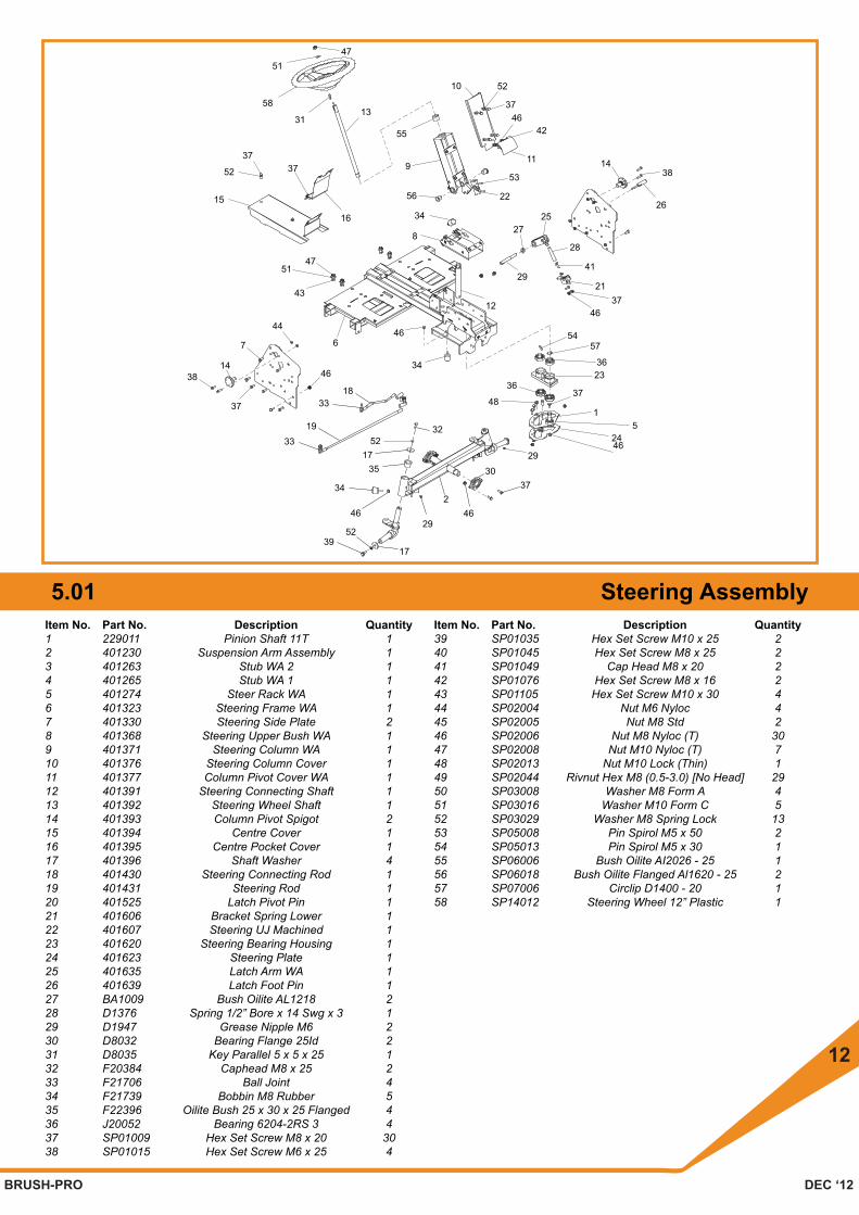
Item No. Part No. Description Quantity1 229011 Pinion Shaft 11T 12 401230 Suspension Arm Assembly 13 401263 Stub WA 2 14 401265 Stub WA 1 15 401274 Steer Rack WA 16 401323 Steering Frame WA 17 401330 Steering Side Plate 28 401368 Steering Upper Bush WA 19 401371 Steering Column WA 110 401376 Steering Column Cover 111 401377 Column Pivot Cover WA 112 401391 Steering Connecting Shaft 113 401392 Steering Wheel Shaft 114 401393 Column Pivot Spigot 215 401394 Centre Cover 116 401395 Centre Pocket Cover 117 401396 Shaft Washer 418 401430 Steering Connecting Rod 119 401431 Steering Rod 120 401525 Latch Pivot Pin 121 401606 Bracket Spring Lower 122 401607 Steering UJ Machined 123 401620 Steering Bearing Housing 124 401623 Steering Plate 125 401635 Latch Arm WA 126 401639 Latch Foot Pin 127 BA1009 Bush Oilite AL1218 228 D1376 Spring 1/2” Bore x 14 Swg x 3 129 D1947 Grease Nipple M6 230 D8032 Bearing Flange 25Id 231 D8035 Key Parallel 5 x 5 x 25 132 F20384 Caphead M8 x 25 233 F21706 Ball Joint 434 F21739 Bobbin M8 Rubber 535 F22396 Oilite Bush 25 x 30 x 25 Flanged 436 J20052 Bearing 6204-2RS 3 437 SP01009 Hex Set Screw M8 x 20 3038 SP01015 Hex Set Screw M6 x 25 4
5.01 Steering AssemblyItem No. Part No. Description Quantity39 SP01035 Hex Set Screw M10 x 25 240 SP01045 Hex Set Screw M8 x 25 241 SP01049 Cap Head M8 x 20 242 SP01076 Hex Set Screw M8 x 16 243 SP01105 Hex Set Screw M10 x 30 444 SP02004 Nut M6 Nyloc 445 SP02005 Nut M8 Std 246 SP02006 Nut M8 Nyloc (T) 3047 SP02008 Nut M10 Nyloc (T) 748 SP02013 Nut M10 Lock (Thin) 149 SP02044 Rivnut Hex M8 (0.5-3.0) [No Head] 2950 SP03008 Washer M8 Form A 451 SP03016 Washer M10 Form C 552 SP03029 Washer M8 Spring Lock 1353 SP05008 Pin Spirol M5 x 50 254 SP05013 Pin Spirol M5 x 30 155 SP06006 Bush Oilite AI2026 - 25 156 SP06018 Bush Oilite Flanged Al1620 - 25 257 SP07006 Circlip D1400 - 20 158 SP14012 Steering Wheel 12” Plastic 1
47
52
56
27
29
25
22
53
11
424637
10
9
55
13
15
52
3737
16
31
58
51
7
44
6
43
5147
8
34
46
37
3814
39
46
34
5232
3319
3318
48
36
34
46
52
17
29
246
3517
3730
2446
29
3623
37
15
12
5457
41
1438
26
28
2137
46

BRUSH-PRO DEC ‘12
13
6.01 Main ChassisItem No. Part No. Description Quantity1 20194 Key 1/4” x 1/4” x 2” Rd End 12 240169 Sensor Angle Plate 13 401200 Engine Plate 14 401204 Frame Weldment LH 15 401205 Frame Weldment RH 16 401209 Upper Lower Drive Plate 27 401239 Backplate WA 18 401269 Control Panel Post 49 401277 Seat Rail Boss 410 401278 Tensioner Offset Plate 111 401297 Rear Tube Face Plate 212 401299 Chassis Front Cover 113 401300 Battery Support Bracket 114 401319 Speed Connecting Rod WA 115 401322 Pedal Connecting WA 116 401342 Belt Tensioner WA 117 401347 Tensioner Bracket WA 118 401348 Belt Finger Brush Pulley 219 401349 Belt Finger Cable Bracket 120 401350 Brake Cable Brcket 121 401351 Axle Engage Rod 122 401367 Wheel Hub 223 401428 Sprocket Drive Shaft WA 124 401429 Pulley Drive Shaft 125 401432 Brake Link 126 401433 Axle Hose 3/4” 127 401434 Tank Hose 5/8” 128 401590 Pulley 80Pcd A Rosca 129 401591 Pulley Belt Disc 130 401601 Tube Axle 231 401602 Axle Support Bracket 132 401608 Centre Cover 133 401611 Belt Guide 234 401616 Bracket Ms Drive Engage 135 401788 Crank Drive Engage WA 136 401789 Rod Drive Engage 137 D1989 Grub Screw M6 x 10 238 D7094 Wheel Bolt M12 839 D8032 Bearing Flange 25ID 340 D8048 Bearing Flange Mounted 20 Bore 141 D8435 Pulley 142 D8907 Washer Copper 1/4” Bsp 243 E1-1062 M8 Spring Washer 844 E1-1063 M10 Spring Washer 645 E1-1134 Hex Set Screw M10 x 80 446 F20664 Reservoir 147 F21623 Jubilee Clip 1A 248 F21706 Ball Joint 550 F21774 Belt V 1EJ Cotton A50 1300 1
Item No. Part No. Description Quantity51 F21784 Key 8 x 7 x 30 252 F21922 Vibration Mount 453 F22078 15T Sprocket 154 F22269 Gearbox 155 F22326 57T Sprocket 156 F35835 Washer 257 F37300 250PCD Pulley 158 F37302 12T 0.5P Sprocket 159 F37358 Spider Coupling MC From 22329 160 F37611 Hydaulic Hose Assy 161 J20017 Knob - Red 162 J209085 Bush Oilite Am1216 - 20 463 J209104 Pin Spirol M6 x 50 164 MD919 Key 1/4” x 1/4” x 1 3/4” Rd End 265 SP01005 Hex Set Screw M8 x 30 366 SP01009 Hex Set Screw M8 x 20 4567 SP01013 Hex Set Screw 3/8” UNF x 2” 168 SP01015 Hex Set Screw M6 x 25 269 SP01035 Hex Set Screw M10 x 25 670 SP01036 Hex Set Screw M8 x 35 871 SP01045 Hex Set Screw M8 x 25 572 SP01049 Cap Head M8 x 20 173 SP01069 Button Head M5 x 12 274 SP01070 Cap Head M2 x 12 275 SP01108 Hex Set Screw M6 x 40 176 SP01123 Csk Socket Screw M5 x 12 377 SP02002 Nut M5 Nyloc (T) 478 SP02003 Nut M6 Std 179 SP02004 Nut M6 Nyloc 380 SP02006 Nut M8 Nyloc (T) 4581 SP02008 Nut M10 Nyloc (T) 482 SP02010 Nut M12 Nyloc (T) 883 SP02012 M8 Thin Lock Nut 184 SP02013 Nut M10 Lock (Thin) 285 SP02018 Nut 3/8” Unf Nyloc (T) 186 SP02028 Nut M16 Nyloc (T) 187 SP02032 Nut M2 Std 288 SP02044 Rivnut Hex M8 (0.5-3.0) [No Head] 1489 SP03008 Washer M8 Form A 490 SP03011 Washer M10 Form A 291 SP03015 Washer M8 Form C 792 SP03029 Washer M8 Spring Lock 293 SP10005 Key 6 x 6 x 30 Rd End 194 SP11008 Tensioner Arm SE15 195 SP11026 Tapered Bush 2012 - 25mm 196 SP12008 Micro Switch Wheel 197 SP13005 Spring Tension 0.91 x 11.1 x 63.5 198 SP15002 Engine Honda GXV390 199 SP26006 Hose Reducer 3/4” To 5/8” 1
41
47
66
14
4263
60
15
47
38
22
3064
80
26
99
68
79
4627
48
1
50
59
76
2928 37
717
33
52
3
51
66 72
4394
53
81
69
8066
80
4010
90
65
39
9786
23
66
12
65
24
18
66
51
93
58
55
95
666
57
98
32
70
9
19
3956
43
75
20
44 69
80
2571
8
6611
80
356280
9177
62
8085
16
17
74
73
3487
31
66
47
21
78
80
80
66
80
84
261
36
13
6692
47
66

R