sonderdruck 862 e - edelstahl rostfrei · the recommendation given in din 18800-1:2008-11, element...
TRANSCRIPT
Sonderdruck 862eAllgemeine bauaufsichtliche ZulassungZ-30.3-6 of 20 April 2009
„Products, fasteners, structural partsmade of stainless steels“
Informationsstelle Edelstahl Rostfrei

Validity
from:
to :
Date: Reference:
Approval number:
App licant:
Subject of approval:
20 April 2009 I 36-1.30.3-1/09
English translation prepared by DIBt - Original version in German language
Z-30.3-6 20 April 2009 *) 30 April 2014
Informationsstelle Edelstahl Rostfrei Sohnstrasse 65 40237 Düsseldorf
Prod ucts, fasteners, structural parts made of stainless steels
The subject of approval mentioned above is herewith generally approved in the field of construction. This allgemeine bauaufsichtliche Zulassung ('national technical approval') comprises 28 pages**) and 33 Annexes.
An allgemeine bauaufsichtliche Zulassung (national technical approval) was granted for this construction product for the first time on 31 May 1974.
*) With amendment of 02 May 2011 **) The number of pages refers to the original approval

Allgemeine bauaufsichtliche Zulassung
Nr. Z-30.3-6
Page 2 of 27 | 20 April 2009
1.21.3-45/11
I GENERAL PROVISIONS
1 With the allgemeine bauaufsichtliche Zulassung ('national technical approval') the fitness for use and the applicability of the subject of approval according to the Landesbauordnungen ('Building Regulations of the Land') has been verified.
2 If, in the allgemeine bauaufsichtliche Zulassung ('national technical approval') requirements are made concerning the special expertise and experience of persons entrusted with the manufacture of construction products and types of construction according to the relevant regulations of the Land following section 17, sub-section 5 Musterbauordnung ('Model Building Code'), it is to be noted that this expertise and experience can also be proven by equivalent verifications from other Member States of the European Union. If necessary, this also applies to verifications presented within the framework of the Agreement on the European Economic Area (EEA) or other bilateral agreements.
3 The allgemeine bauaufsichtliche Zulassung ('national technical approval') does not replace the permits, approvals and certificates prescribed by law for carrying out building projects.
4 The allgemeine bauaufsichtliche Zulassung ('national technical approval') will be granted without prejudice to the rights of third parties, in particular private property rights.
5 Notwithstanding further regulations in the "Specific Provisions" manufacturers and distributors of the subject of approval shall make copies of the allgemeine bauaufsichtliche Zulassung ('national technical approval') available to the user and point out that the allgemeine bauaufsichtliche Zulassung ('national technical approval') has to be available at the place of use. Upon request copies of the allgemeine bauaufsichtliche Zulassung ('national technical approval') shall be placed at the disposal of the authorities involved.
6 The allgemeine bauaufsichtliche Zulasssung ('national technical approval') may be reproduced in full only. Publication in the form of extracts requires the consent of Deutsches Institut für Bautechnik. Texts and drawings of advertising brochures may not be in contradiction to the allgemeine bauaufsichtliche Zulassung ('national technical approval'). Translations of the allgemeine bauaufsichtliche Zulassung ('national technical approval') have to contain the note "Translation of the German original, not checked by Deutsches Institut für Bautechnik".
7 The allgemeine bauaufsichtliche Zulassung ('national technical approval') is granted until revoked. The provisions of the allgemeine bauaufsichtliche Zulassung ('national technical approval') can subsequently be supplemented and amended in particular, if this is required by new technical findings.

Allgemeine bauaufsichtliche Zulassung
Nr. Z-30.3-6
Page 3 of 27 | 20 April 2009
1.21.3-45/11
II SPECIFIC PROVISIONS
1 Subject of approval and field of application
1.1 Subject of approval Subject of approval are products and fasteners made of stainless steels according to
DIN EN 10088-1:2005-09 as well as components and their connections produced from them according to DIN 18800-1 to -4 and -7:2008-11, and the engineering standards mentioned in section 1.2.
The steel grades and their product forms for components are given in Annex 1, Table 1. Stainless steels for components are used in the strength classes S235, S275, S355, S460 and S690, where the strength classes are indicated in N/mm² according to the yield strengths Rp0.2. The strengths following each the lowest one are achieved through cold working.
Stainless steels for fasteners are assigned to steel groups according to DIN EN ISO 3506-1 and -2:2010-04 in the strength classes 50, 70 and 80, where the strength classes are indicated in kN/cm² according to the tensile strengths Rm.
Components may be the products themselves or produced from them according to given rules. Products shall have a minimum thickness of min t or rather min d = 1.5 mm, the thread diameters of the fasteners shall be at least M 6.
Not subject of this national technical approval are:
- high-strength tension members according to DIN 18800-1:2008-11
- multi-part compression members according to DIN 18800-2:2008-11
- composite structures made of steel and concrete according to DIN 18800-5:2007-03
- structural parts made of hollow sections according to DIN 18808:1984-10 of the strength classes S460 and S690
- free-standing steel chimneys according to DIN V 4133:2007-07
- rivets according to DIN 18800-1:2008-11
1.2 Field of application This national technical approval applies to components and connections under
predominantly static loads
- in steel structural engineering according to DIN 18801:1983-09,
- in supporting structures made of hollow section according to DIN 18808:1984-10
up to strength class S355,
- in round thin-walled silos according to DIN 18914:1985-09,
- in above-ground cylindrical flat-bottom tanks according to DIN 4119-1:1979-06 and
- in steel radio towers and masts according to DIN V 4131:2008-09.
together with DIN 18800-1 to -4 and -7:2008-11 and, as far as this concerns engineering standards, of the Anpassungsrichtlinie Stahlbau ('adjustment directive for steel structures') with modification and supplement - edition December 2001.
For façade components and their anchoring elements and fasteners, section 3.3.11 shall be taken into account for pulsating and alternating load through atmospheric changes of temperature.
For assessing their corrosion resistance, stainless steels are divided into corrosion resistance classes; see Annex 1, Table 1. The selected corrosion resistance classes shall fulfill the requirements put on the components for corrosion protection, also with regard to the time of protection.

Allgemeine bauaufsichtliche Zulassung
Nr. Z-30.3-6
Page 4 of 27 | 20 April 2009
1.21.3-45/11
The steel grades mentioned in Table 1 can be applied for temperatures down to -40 °C. This does not require any proof for austenitic steels. For the steel grades of the material numbers 1.4003, 1.4016, 1.4362 and 1.4462, a sufficient notched-bar impact value with ISO-V-samples shall be proven.
2 Characteristics of the construction product
2.1 Production, properties and composition of products and fasteners 2.1.1 Steel grades, product forms, strength classes The products consist of steel grades in the product form according to Annex 1, Table 1 and
the fasteners of strength classes according to Annex 2, Table. 2.
2.1.2 Technical delivery conditions for prodcuts according to Table 1 of Annex 1 2.1.2.1 Products without or before cold working
The technical delivery conditions apply according to:
- DIN EN 10088-4:2010-01 for sheet/plate and strip,
- DIN EN 10088-5:2009-07 for bars, rods, wire and sections,
- DIN EN 10296-2:2006-02 for welded tubes,
- DIN EN 10297-2:2006-02 for seamless tubes.
2.1.2.2 Products after cold working
The steel grades for products according to Table 1 given in Annex 3, Table 3 shall have the mechanical properties given there at ambient temperature. The proofs shall be furnished such as it is established in the standards in section 2.1.2.1 for the state before cold working.
2.1.2.3 Choice of steel grade classes
The recommendation given in DIN 18800-1:2008-11, element 403, applies analogously. Accordingly, stainless steels shall meet the same requirements as common carbon steels with regard to notched-bar impact work. Since austenitic stainless steels are not susceptible to brittle fracture up to temperatures of -40 °C, t hey can be applied up to these temperatures without any further proof.
For ferritic steels with the material numbers 1.4003 and 1.4016 as well as for the austenitic-ferritic steel grades with the material numbers 1.4362 and 1.4462 at least one notched-bar impact work of 40 J with ISO-V-samples shall be proven at -40 °C. For long products the proof shall be furnished on longitudinal samples and for flat products on transverse samples. The value of the notched-bar impact work is determined as mean value of 3 samples, where at most one single value around maximum 30 % may be below 40 J.
2.1.3 Technical terms of delivery for fasteners according to Annex 2, Table 2 The technical terms of delivery apply according to:
- DIN EN 15048-1:2007-07
- DIN EN ISO 3506-1:2010-04 for screws and threaded rods,
- DIN EN ISO 3506-2:2010-04 for nuts, and as far as applicable, also for washers.
2.1.4 Suitability for welding; filler metals 2.1.4.1 General
Except for steel grades with the material numbers 1.4016, 1.4567 and 1.4578, as far as approved filler metals are available according to 2.1.4.2 and no restrictions are made in 4.6.2 to 4.6.8, all steels grades are approved for the following welding processes:

Allgemeine bauaufsichtliche Zulassung
Nr. Z-30.3-6
Page 5 of 27 | 20 April 2009
1.21.3-45/11
Manual metal arc welding (111), tungsten inert gas welding (141), metal inert gas welding (131), metal active gas welding (135), tubular cored metal arc welding with active gas shield (136), submerged arc welding (12), arc stud welding (783), drawn arc stud welding with tip ignition (786), plasma MIG welding (151), resistance spot welding (21), flash welding (24), resistance butt welding (25), friction welding (42), laser beam welding (52) and electron beam welding (51).
Welding of the steel grades with the material numbers 1.4016, 1.4567 and 1.4578 is not regulated in this national technical approval.
2.1.4.2 Welded joints, filler metals
(1) Except for joints of components made of the same stainless steel grades according to this national technical approval, such joints of components made of different steel grades - hereafter named mixed joints - are allowable. It may concern components made of:
- different stainless steel grades according to this national technical approval
- stainless steel grades according to this national technical approval and carbon steels according to DIN 18800-1:2008-11 as well as technically approved high-strength carbon steels.
(2) Welding consumables for joints of components with the same stainless steel grades are indicated in Annex 4, Table 4.
(3) In welded joints made of different austenitic steel grades according to Table 1, the filler metals of one as well as of the other steel grade may be applied according to Table 4.
(4) In welded joints of components made of austenitic steel grades and such of the ferritic steel grade with the material number 1.4003 filler, metals shall be used according to Annex 5, Table 5. Thermal conduction shall be oriented towards austenitic steel.
(5) In mixed joints of components made of the ferritic steel grade with the material number 1.4003 or austenitic steel grades on the one hand and such made of carbon steels according to DIN 18800-1:2008-11 as well as of the technically approved high-strength carbon steels on the other hand, filler metals according to Annex 5, Table 6 shall be used. Thermal conduction is oriented to that for high-strength carbon steels, where preheat temperatures and interpass temperatures above 150 °C shall be av oided. Incidentally, DIN EN 1011-2:2001-05 shall be taken into account for fine grain steels.
(6) In mixed joints of components made of ferritic-austenitic steel grades with the material numbers 1.4362 or 1.4462 on the one hand and components made of carbon steels according to DIN 18800-1:2008-11 as well as the technically approved high-strength carbon steels on the other hand, the filler metal given for the steel grades with the material numbers 1.4362 and 1.4462 in Table 4 shall be preferred. The filler metals according to Annex 6, Table 7 may also be used. Paragraph (5) applies for thermal conduction.
2.1.5 Limit dimensions of the products and fasteners 2.1.5.1 Limit dimensions of the products
The products or rather their sections shall have a thickness of at least 1.5 mm.
Unless no additional restrictions are made in other sections of this national technical approval, to the maximum thicknesses apply
- the specifications in DIN EN 10088-4:1012-01 and DIN EN 10088-5:2009-07 of annealed products and
- the specifications in Annex 6, Table 8 of cold-worked products.
The maximum thicknesses for welded components of cold-worked and annealed materials result from Tables 8 and 9 in Annex 6 and 7.

Allgemeine bauaufsichtliche Zulassung
Nr. Z-30.3-6
Page 6 of 27 | 20 April 2009
1.21.3-45/11
2.1.5.2 Limit dimensions of the fasteners
The minimum diameter of thread is M 6.
For different steel grades, the maximum nominal diameters result from Table 2. The mechanical properties according to DIN EN ISO 3506-1 and -2:2010-04 shall also be ensured for the dimension ranges mentioned here compared to the standard as well as checked and controlled according to section 2.3.
2.1.6 Corrosion protection of the construction products 2.1.6.1 Requirements
(1) For reasons of stability, components and fasteners require no corrosion protection, if
- the material used corresponds to corrosion resistance class according to Table 1, which is at least required after corrosion load according to Table 1a, and
- no deviating requirements result from sections 2.1.6.2 to 2.1.6.7.
Note:
Corrosion resistance classes integrate different alloys showing a comparable corrosion resistance under the same corrosion loads. The selection of materials according to Table 1a only includes technical requirements, but not decorative consistency (e.g. unwanted discolorations in consequence of a slight corrosive attack).
If there are high optical requirements, a particular importance is attached to type of design and surface finish of the components. Finely machined, smooth and flawless surfaces shall be ensured. The selection of a higher corrosion resistance class offers no replacement for this. The factory deliverable surfaces 2B, 2R, 1G, 2G, 1K, 2K for sheet/plate and strip or 1G, 2G, 2B and 2P for bars, rods, wire and sections specified in DIN EN 10088-4:2010-01 or DIN EN 10088-5:2009-07 meet these requirements.
(2) In each single case it shall be checked what kind of corrosion load can be expected for the particular structure or structural part.
2.1.6.2 Corrosion protection of components and fasteners in indoor swimming pools
Under the conditions mentioned in Annex 7, Table 10, only the steel grades given there shall be used in indoor swimming pools.
2.1.6.3 Corrosion protection of welded or thermally cut components
(1) In the corrosion resistance classes III and IV, a post-treatment of the cutting edge and the welds is always necessary to remove annealing colours. Welds shall be constructional arranged in a way that areas in which annealing colours cannot be removed (e.g. in gaps and in overlaps) are completely closed through the weld. In exceptional cases, open gaps and overlaps can be protected through sealing by suitable sealant against entry of corrosive media.
The removal of annealing colours and the closure of gaps and overlap areas is dispensable, if they are constructively arranged in such areas for which input and accumulation of corrosion causing media can be safely excluded.
For minimizing on-site welding work, especially for structures for which a suitable post-treatment is aggravated through accessibility, system solutions with a high degree of factory prefabrication and defined surface conditions shall be prioritized.
For the corrosion resistance classes I and II, darker annealing colours darker than straw-yellow shall be removed.
Notice: Annealing colours developing on the back of a steel component due to the heat input from the welding process may remain if the affected surface abuts on a solid component and coupled with it, e.g. welding to anchor plates.
(2) To avoid a sensitization against intergranular corrosion after welding, the highest thicknesses according to Annex 7, Table 9 shall be taken into account for the steel grades with the numbers 1.4301 and 1.4401.
Allgemeine bauaufsichtliche Zulassung
Nr. Z-30.3-6
Page 7 of 27 | 20 April 2009
1.21.3-45/11
(3) For welded joints of stainless steel with other steel, the explanations regarding bimetal corrosion (contact corrosion) in section 2.1.6.5 apply.
2.1.6.4 Corrosion protection of mechanically treated components
During mechanical treatment of stainless steels as well as removal of annealing colours according to section 2.1.6.3, no particles producing extraneous rust shall get into the surface. An application of tools by means of which non-alloy or low-alloy steel was previously treated or wire brushes made of such steels shall be avoided accordingly. If this is impossible in the single case, the surface for removing the particles producing extraneous rust shall be post-processed (e.g. etching, grinding).
Notice: Annealing colours developing through mechanical cutting, for example on cut edges, may remain.
2.1.6.5 Corrosion protection of connections with other metals
(1) Bimetal corrosion may occur for an electrically conductive contact of different metals. The appearance of bimetal corrosion is bounded to the existence of a liquid (electrolyte solution) in the contact area, i.e. an endanger basically exists only if the corresponding joint is often and long-lasting moist. In the most general sense, bimetal corrosion in an aqueous environment (also in the soil) has a bigger significance than at the atmosphere where it is only effective as long as water does not dry off. If there are impurities, hydroscopic or constantly damp deposits, self-priming sealings or constantly dump crevices, damages through bimetal corrosion are possible even under conditions of a usually harmless atmospheric load.
(2) On joints with components made of non-alloy or low-alloy steel, galvanized steel or aluminum for example, a corrosion risk through bimetal corrosion may only exist for the less noble contact materials; bimetal corrosion practically does not occur on stainless steels themselves.
(3) If necessary, bimetal corrosion shall be prevented by isolating stainless steel electrically from less noble metal through suitable plastics molding. Electric isolation shall be complete and also must not be abolished indirectly offside the joints. If necessary several components shall be coated in order to achieve a protection of the less noble partner from bimetal corrosion.
(4) Welds shall be arranged in that way that the position of the contact area does not expect any corrosion (e.g. inner areas without condensation). Otherwise, the joint shall receive a corrosion protection granting a constant protection for the non-alloy and low alloy steel in dependence on the corrosiveness of the environment and on the protection period. The selected corrosion protection shall be extended at least to the directly adjacent area of the stainless steel in order to avoid the formation of corrosion cells in the transition area.
2.1.6.6 Galvanizing, contact with molten zinc
Hot-dip galvanizing of components made of stainless steels is not allowed. When coming into contact of stainless steel with molten zinc which may occur upon hot-dip galvanizing - i.e. of components with mixed joints - or in the event of fire, the risk of an immediate embrittlement exists. This contact shall not be excluded if the stability of the structure is not jeopardized through an embrittlement of the stainless steel.
2.1.6.7 Corrosion protection of anchoring, reinforced concrete construction and in masonry construction.
Welded joints and other metallically conductive contact points between stainless steels and other steel grades are only allowable without additional corrosion protection, if that part of the stainless steel free of annealing colours weaves at least 5 cm into the concrete.

Allgemeine bauaufsichtliche Zulassung
Nr. Z-30.3-6
Page 8 of 27 | 20 April 2009
1.21.3-45/11
2.2 Package, transport, storage and marking of the products and the fasteners 2.2.1 Package, transport, storage The products and fasteners shall be packed, transported and stored this way that the
material and corrosion behaviour is considered. The contamination of particles producing extraneous rust into the surface shall also be avoided. If this is impossible in the single case, the surface for removing the particles producing extraneous rust shall be post-processed (e.g. etching, grinding).
2.2.2 Marking 2.2.2.1 Products
(1) For CE-marking and labelling of the annealed products the provisions in DIN EN 10088-4:2010-01 or DIN EN 10088-5:2009-07, Annex ZA apply.
Cold-worked products or the enclosed leaflet shall be marked by the manufacturer with the conformity mark Ü (Ü-mark) in accordance with the decrees on conformity marking of the States of the Federal Republic of Germany. The name of the manufacturer and the number of this national technical approval shall be declared in the conformity mark. Marking is only allowed if the conditions given in section 2.3 are satisfied.
Furthermore the products shall be marked according to DIN EN 10088-4:2010-01 or DIN EN 10088-5:2009-07, Section 9.
(2) The marking according to paragraph (1) shall be preserved if only parts of the products are used. If necessary the marking shall be transferred to the single parts by a person in charge of the manufacturer. An in-house defined short mark may be used for the marking of small parts (meant are small parts of the initial products as bars and not small parts of a fabricator as e. g. anchor channels). All cutting of the products shall be recorded.
(3) All products shall be delivered with inspection certificates 3.1 according to DIN EN 10204:2005-01.
2.2.2.2 Fasteners
(1) For CE-marking of bolts according to DIN EN ISO 3506-1:2010-04 and nuts according to DIN EN ISO 3506-2:2010-04 DIN EN 15048-1:2007-07, Annex ZA applies.
Bolts and nuts not included in DIN EN ISO 3506-1 or -2:2010-04 (e. g. > M39) as well as other threaded parts, the package or the enclosed leaflet shall be marked by the manufacturer with the conformity mark Ü (Ü-mark) in accordance with the decrees on conformity marking of the States of the Federal Republic of Germany. The name of the manufacturer and the number of this national technical approval shall be declared in the conformity mark. Marking is only allowed if the conditions given in section 2.3 are satisfied. Furthermore the fasteners shall be marked with the steel name or steel number according to the delivery conditions in section 2.1.2 and 2.1.3 of this national technical approval. The bolts, nuts and threaded parts shall be marked according to Table 2 in the basis of DIN EN ISO 3506-1 and -2:2010-04.
(2) The fasteners shall be delivered with an inspection certificate 3.1 according to DIN EN 10204:2005-01.
2.3 Verification of conformity 2.3.1 General (1) The following provisions of Section 2.3 apply to the products and fasteners marked with
the mark of conformity (Ü-Zeichen) ('Ü-mark') according to Section 2.2.2.
(2) Proof of conformity of the products and fasteners made of stainless steels manufactured according to this national technical approval, with the provisions of this national technical approval, shall be delivered by means of a certificate of conformity issued for each manufacturing plant and based on factory production control and continuous surveillance including initial-type testing of the construction product in accordance with the following provisions.

Allgemeine bauaufsichtliche Zulassung
Nr. Z-30.3-6
Page 9 of 27 | 20 April 2009
1.21.3-45/11
(3) The manufacturer of the products and / or fasteners shall involve an accredited certification body and an accredited monitoring body for the issuing of the certificate of conformity and for the outside monitoring, including the related product inspections.
(4) The declaration that a certificate of conformity has been granted shall be given by the manufacturer by marking the construction products with the mark of conformity (Ü-Zeichen) ('Ü-mark') stating the intended use.
(5) The certification body shall submit, for information, a copy of the relevant certificate of conformity to the Deutsches Institut für Bautechnik. Additional a copy of the initial type testing report shall be submitted to the Deutsches Institut für Bautechnik for information.
2.3.2 Factory production control (1) Every manufacturing plant shall have a factory production control system and exercise
factory production control. Factory production control means the permanent control of production exercised by the manufacturer by which the latter ensures that the products and fasteners produced by him are in conformity with this national technical approval.
(2) For the tests, the range of tests as well as for taking of samples the technical delivery conditions for products of corrosion resisting steels according to Section 2.1.2 of this national technical approval apply. For bolts, threaded bars, nuts and washers DIN EN ISO 3269:2000-11 in conjunction with DIN EN ISO 3506-1:2010-04 and DIN EN ISO 3506-2:2010-04applies.
A tightness test (inside pressure test according to DIN EN 10296-2:2006-02 and DIN EN 10297-2:2006-02) may be omitted for pipes
(3) The results of factory production control shall be recorded and evaluated. The records shall include at least the following information:
- designation of the construction product or the initial materials and the components
- type of control,
- date of manufacture and date of testing of the construction product or the initial materials and the components,
- results of control and and as far as it applies comparison with requirements,
- signature of the person responsible for factory production control.
(4) The records shall be kept for at least five years and shall be presented to the inspection body involved in surveillance. On request, they shall be presented to the Deutsches Institut für Bautechnik and to the relevant supreme building authority.
In case of unsatisfactory test results the manufacturer shall immediately take the measures necessary to rectifying the fault. Construction products not meeting the requirements shall be handled in a way that confusion with the products in compliance with the specifications will be excluded. As soon as the fault has been rectified - as far as technically possible and required for evidence that the fault has been rectified - the corresponding test shall be repeated immediately.
2.3.3 Surveillance (1) Factory production control exercised in every manufacturing plant shall be continuously
verified by surveillance, but at least once a year.
In the framework of surveillance, an initial-type testing of the construction product shall be performed and also samples can be taken for audit-testing. Sampling and testing are in the responsibility of the approved body.
(2) In the framework of surveillance the following tests shall be executed on the products released for delivery:
- at least 3 tensile tests at ambient temperature,
- for the steel grades 1.4003, 1.4016, 1.4362 and 1.4462 at least one set (3 samples) charpy tests at longitudinal specimen,
Allgemeine bauaufsichtliche Zulassung
Nr. Z-30.3-6
Page 10 of 27 | 20 April 2009
1.21.3-45/11
- visual testing of surface conditions,
- check of geometry,
- product analyses.
(3) For fasteners DIN EN ISO 3269:2000-11 applies in connection with DIN EN ISO 3506-1 and -2:2010-04.
(4) Further details shall be taken from the technical delivery conditions in accordance with Section 2.1.2 and 2.1.3
(5) The results of the certification and surveillance shall be kept for at least five years. On request, it shall be presented by the certification body or inspection body to the Deutsches Institut für Bautechnik and to the relevant supreme building authority.
3 Provisions for the design and calculation of structural parts and joints
3.1 General 3.1.1 Technical rules to be applied DIN 18800-1 to 4:2008-11 and the engineering standards mentioned in section 1.2 applies
and also, as far as this concerns engineering standards, the ATP Directive for steel construction with modification and supplement - edition December 2001, as far as no other definitions are stated following behind. The regulations concerning the construction and design in section 4 of this national technical approval are to be taken into account as wells.
3.1.2 Different steel grades in a supporting structure Deviating from DIN 18800-1:2008-11, element 502 shall be taken into account:
If different steel grades are used in a supporting structure, the different coefficients of thermal expansion shall be considered. This applies for temperature changes due to working process or weather as well as for such that occur during fabrication through welding and in the event of fire for example.
3.2 Design 3.2.1 Bolted connections (1) Friction grip connections according to DIN 18800-1:2008-11, element 506, are not
subject of this national technical approval.
(2) Owing to possible creep phenomena with tensile loads, the planned pre-stress may not be utilized also with regard to the serviceability.
(3) With regard to corrosion protection for bolt spacings according to line 5 required in DIN 18800-1:2008-11, Table 7, footnote, supplementary to element 513 applies: The corrosion protection assumed for the enlargement of the edge distances and hole spacings indicated in line 5 of Table 7 of DIN 18800-1:2008-11 is given for the steel grades according to this national technical approval if the requirements are met according to section 2.1.6.
(4) If welding is envisaged on fasteners, they are basically classified into property class 50.
3.2.2 Welded joints 3.2.2.1 Limitation of weld thicknesses
(1) For welded joints of components made of austenitic steels with those made of ferritic steels, the weld thickness may be not more than 16 mm unless the qualification for the bigger values has not been proven by an earlier production control test according to DIN EN ISO 15613.
(2) Supplementary to DIN 18800-1:2008-11, Element 519, applies: For cross-section parts with thicknesses of 1.5 mm ≤ t < 2 mm, the fillet weld thickness a = min t should be selected.

Allgemeine bauaufsichtliche Zulassung
Nr. Z-30.3-6
Page 11 of 27 | 20 April 2009
1.21.3-45/11
3.2.2.2 Welding in cold-formed areas
(1) Welding in cold-formed areas is admissible taking into account section 4.3. Deviating from DIN 18800-1:2008-11, Element 522, the regulations according to DIN 18800-1:2008-11, Table 9 does not apply.
(2) Regarding the ferritic steel grade with the material number 1.4003 cold forming of maximum 5 % is admissible for welded components, since with a higher cold forming and an additional heating, a grain growth with loss of ductility may occur.
3.3 Structural design 3.3.1 Characteristic values of mechanical properties for proofs of structural safety and
serviceability 3.3.1.1 Steel grades of the products according to Annex 1, Table 1
(1) For calculations according to the theory of first order, the characteristic values according to Appendices 8.1 and 8.2, Table 11 apply.
(2) For calculations according to the theory of second order and other proofs of stability according to DIN 18800-2 to -4:2008-11, the values according to Annex 8.1 and 8.2 Table 11, column 3 apply. For cold-worked states of the steel grades
- 1.4003, 1.4016, 1.4567, 1.4318, 1.4578, 1.4439, 1.4362, 1.4539, 1.4565, 1.4529 and 1.4547, however, only the characteristic values fy,k indicated in column 3 of Table 11 for the annealed materials,
- 1.4301, 1.4307, 1.4401, 1.4404, 1.4541, 1.4571 and 1.4462 only the characteristic values fy,k of the lower strength class next to the specified strength class indicated in column 3 of Table 11, but not more than 355N/mm² shall be set, unless higher values are verified and granted through a product related approval test. The latter applies for welded hollow sections of Stala Tube Oy, Lahti, Finland. For the cold-worked states of the steel grades,
- 1.4301, 1.4571 up to strength class S460,
- 1.4318 strength class S355 only
the characteristic values of the yield strength can be set for them even for the proof of stability without any reduction.
(3) For the modulus of elasticity E, the values according to Table 11, column 6 are to be set as characteristic values, unless the load is not determined through restraints. For the calculation of constraint stresses, the values according to Table 11, column 7 apply.
3.3.1.2 Materials of the fasteners according to Annex 2, Table 2.
The characteristic values according to Annex 9, Table 12 apply. If welding is envisaged on fasteners, the values of strength class 50 are to be always used for the design.
3.3.2 Stress strain relations 3.3.2.1 General
(1) Also far below the yield strength Rp0.2, the strains ε depend non-linearly on the stresses (Fig. 1a in Annex 14). They can be specified through the power law
n
ky,fσ
0,002Eσ
ε
⋅+=
with
n = 6 for σ ≤ fy,k
n = 17 for σ > fy,k
fy,k according to 3.3.1.1(1) or 3.3.1.1(2)
E according to 3.3.1.1(3)

Allgemeine bauaufsichtliche Zulassung
Nr. Z-30.3-6
Page 12 of 27 | 20 April 2009
1.21.3-45/11
(2) Instead of this non-linear stress strain relation according to paragraph 1, the proofs may be based upon a linear elastic perfect plastic stress strain relation according to the sections 3.3.2.2 or 3.3.2.3.2.
3.3.2.2 Stress-strain relation for proofs according to the theory of first order.
For calculations according to the theory of first order, the linear elastic perfect plastic stress-strain relation according to Fig. 1b in Annex 14 may be arranged.
3.3.2.3 Stress and strain relation for proofs according to the theory of second order.
3.3.2.3.1 General
For calculations according to the theory of second order, the hardening range of the stress-strain relation shall not be used. This means that the power law is restricted to
n
ky,fσ
0,002Eσ
ε
⋅+=
with
n = 6 for σ ≤ fy,d
and for
n
ky,
y,dy,d
f
f0,002
E
fε
⋅+>
σ = fy,d applies.
3.3.2.3.2 Linearization of the strain-stress relation
(1) For calculations according to the theory of second order, instead of a stress-strain relation according to 3.3.2.3.1, a linear-elastic perfect plastic stress-strain may be assumed either
- according to Fig. 1c in Annex 14 with a non-reduced yield strength fy,k and the secant modulus Esek,y or
- according to Fig. 1d in Annex 14, assumed with a reduced yield strength red fy,k and the corresponding secant modulus Esek. For red fy,k, Esek and Esek,y applies:
red fy,k = fρ � fy,k
Esek = 5f
ky,
ρfE
0,0021
E
⋅⋅+ and Esek,y =
ky,fE
0,0021
E
⋅+
with
fρ yield strength reduction factor
red fy,k and Esek are to be calculated with the same yield strength reduction factor fρ .
Subject to the conditions
ky,
ky,f f
fredρ =
M
ky,fv
fρσ
γ⋅≤

Allgemeine bauaufsichtliche Zulassung
Nr. Z-30.3-6
Page 13 of 27 | 20 April 2009
1.21.3-45/11
with
vσ effective stress according to DIN 18800-1:2008-11, eq. (36) may be freely selected.
For fρ ≤ 0.40, the value E according to Table 11, column 6 may be arranged for Esek.
Note 1:
The second condition corresponds to the proof according to DIN 18800-2:2008-11, element 121. Accordingly, it is to be proven that the effective stress is not bigger than the design value of the reduced yield strength.
Note 2:
For fρ = 1, the stress-strain relation according to Fig. 1c in Annex 14 is obtained as a special case
red fy,k = fy,k and Esek = Esek,y
applies.
Note 3:
Remark on the determination of the yield strength reduction factor fρ
- If the effective strength σv is known, then fρ follows from:
ky,
Mvf fσρ
γ⋅=
- If the effective strength vσ is still unknown, fρ shall be estimated at first. The suitable
selection of fρ depends on the slenderness ratio of the component to be investigated. It
is advisable to select fρ = 1 for compact components, fρ = 0.4 for very slender
components, and fρ between 0.5 and 0.9 for slender to medium slender components.
In order to obtain the mathematically biggest stress, fρ shall be varied.
(2) For all secant moduli Esek the corresponding shear modulus is defined with
Gsek = µ)2(1
Esek
+
and
µ = 0.3 3.3.2.3.3 Design values of the variables Esek, Gsek and red fy,k
With regard to the variables Esek, Gsek and red fy,k or in the special case according to Fig.1c in Annex 14, the variables Esek,y and Gsek,y are characteristic values in terms of DIN 18800-1:2008-11, Element 304.
The design value of the reduced yield strength is
red fy,d = M
ky,f
M
ky,fρfred
γ
⋅=
γ
⋅
If a secant modulus Esek > Esek,y is assumed, thus fρ < 1, for the stress-strain relations, all proofs shall be furnished with red fy,d.
3.3.3 Delimitation criteria For proofs according to DIN 18800-1:2008-11, elements 728, 739 and 740, the secant
modulus Esek,y according to 3.3.2.3.2(1) shall be applied instead of the E-modulus.
This also applies for calculating deformations and buckling loads used.
Allgemeine bauaufsichtliche Zulassung
Nr. Z-30.3-6
Page 14 of 27 | 20 April 2009
1.21.3-45/11
3.3.4 Service strength The conditions (25) and (26) in DIN 18800-1:2008-11 are to be substituted by:
∆σ < 21 N/mm² for (25)
n < 107 (21/∆σ)³ for (26) 3.3.5 Proofs according to DIN 18800-1:2008-11 3.3.5.1 Force applications
The limit force FR,d according to DIN 18800-1:2008-11, element 744, is to be reduced to 74 % of the values determined according to the equations (29) and (30).
The maximum value 60 indicated in element 744 regarding the web slenderness h/s, for which safety against buckling does not have to be proven, is to be substituted by 32.
3.3.5.2 Hole weakening
The proof is to be furnished independent on the bearing stress proof element (805) in DIN 18800-1:2008-11. The proof whether the deduction of holes may be disregarded, shall be furnished using equation (27) in element 742.
3.3.5.3 Limiting values limit (b/t) and limit (d/t) according to Tables 12 to 14 in DIN 18800-1:2008-11
When applying DIN 18800-1:2008-11, element 745, with Tables 12 to 14, the quotient
M1σ
240γ⋅
shall be substituted by Baustahl
sek
M1 E
E240 ⋅γ⋅σ
with Esek according to 3.3.2.3.2(1) with ky,
M1f fσρ
γ⋅=
and EBaustahl = 210000 N/mm² ((EBaustahl = Ecarbon steel))
3.3.5.4 Limiting values limit (b/t) and limit (d/t) according to Table 15 in DIN 18800-1:2008-11
When applying DIN 18800-1:2008-11, element 753, Table 15, the quotient
ky,f
240 shall be substituted by
Baustahl
ysek,
ky, E
E
f240 ⋅
with Esek,y according to 3.3.2.3.2(1),
and EBaustahl = 210000 N/mm²
3.3.5.5 Limiting values limit (b/t) and limit (d/t) according to Table 18 in DIN 18800-1:2008-11
The indications in section 3.3.5.4 regarding DIN 18800-1:2008-11, element 753, Table 15 do also apply for the use of element 758, Table 18.
3.3.5.6 Stress resistance of screws on shear lag
Deviating from element 804 in DIN 18800-1:2008-11, the steel grades with the serial number 3 to 6 and 8 to 11 according to Table 2 apply to αa in equation (47):
αa = 0.75 for screws of strength class 50,
αa = 0.68 for screws of strength class 70 and 80.
The steel grades with the serial number 12 to 17 according to Table 2 apply uniformly to αa = 0.5 for screws of the strength classes 50, 70 and 80.
The proof shall be always furnished using the stress area As independent on the location of the shear plane.
Note:
That has to do with the fact that these screws may show locally different mechanical properties in contrast to screws made of non-alloy or low-alloy steel.

Allgemeine bauaufsichtliche Zulassung
Nr. Z-30.3-6
Page 15 of 27 | 20 April 2009
1.21.3-45/11
3.3.5.7 Strength capacity of weld joints
(1) Annex 8.1 and 8.2, Table 11 apply to the welding processes 111, 121, 131, 135, 136 and 141, Table 11.
Note: For the remaining welding processes, see 4.6.3 to 4.6.8.
(2) Deviating from DIN 18800-1:2008-11, for the calculation of the limit weld stress regarding weld joints of steels of this national technical approval
- with each other or
- with carbon steels according to DIN 18800-1:2008-11, element 401 or
- with fine-grained steels according to national technical approvals
the smaller value, being the result of this combination from Annex 8.1 and 8.2, Table 11, column 4 and from Annex 5 and 6, Tables 5 to 7 from the columns 4, the smaller value is to be set for fy,k. In addition, the proof of load-bearing capacity is to be furnished for the weld joint with the value fy,k of carbon steel or fine-grained steel in case of joints of different steel types according to Table 6 and 7.
3) For the αw-values, the values of Annex 9, Table 13 of this national technical approval are to be used instead of the values indicated in Table 21 in DIN 18800-1:2008-11. For mixed compounds according to Table 6 and 7, the αw -value according to Table 21 in DIN 18800-1:2008-11 or according to the corresponding national technical approval is to be applied in the proof of the load-bearing capacity for the weld joint with the values fy,k of carbon steel or fine-grained steel.
(4) DIN 18800-1:2008-11, element 833 with Table 22 shall not be applied.
3.3.6 Proofs according to DIN 18800-2, -3 and -4:2008-11 3.3.6.1 Basics on the proof of safety against instable failure
3.3.6.1.1 Stress-strain relation
For proofs of safety against instable failure, except for simplified proofs in sections 3.3.7 to 3.3.9, in all conditions of DIN 18800-2 and -3:2008-11 corresponding to section 3.3.2.3.2, the following substitutions shall be made:
fy,k through red fy,k
fy,k through red fy,k
E through Esek
G through Gsek
Correspondingly, all factors dependent on these basic parameters are to be marked with the index sek and used in the conditions.
In case of a proof corresponding to section 3.3.2.3.1, with
red fy,d = max σv
also red fy,k, Esek and Gsek are defined through the result of the non-linear calculation.
Note:
Examples:
Nki,sek = ( )
2k
sek2
s
EI⋅π
Npl,sek,d = red fy,d � A
sek
sek (EI)N
Iε ⋅=

Allgemeine bauaufsichtliche Zulassung
Nr. Z-30.3-6
Page 16 of 27 | 20 April 2009
1.21.3-45/11
ky,
sekseka, fred
E⋅π=λ
2
2sek
2
e,sek bt
)µ(112
Eσ
⋅−⋅
⋅π=
In the special case red fy,k = fy,k and Esek = Esek,y
3.3.6.1.2 Simplified proofs
For the stability cases flexural buckling, lateral torsional buckling and plate buckling, κ-values for stainless steels are indicated in sections 3.3.7 and 3.3.8, which might be also applied to webs that are assumed to be straight with plane thin-walled cross-section parts following the conditions in section 3.3.7.10. In these κ-values, the non-linear material behavior is taken into account.
Therefore, a simplified proof with E = 170000N/mm² and fy,k according to section 3.3.1.1(2) can be furnished in the mentioned cases.
3.3.7 Proofs according to DIN 18800-2:2008-11
3.3.7.1 One-piece members according to DIN 18800-2:2008-11, section 3
The proofs may be furnished according to DIN 18800-2:2008-11, section 3, considering the definition in the following sections 3.3.7.2 to 3.3.7.9 using E = 170000N/mm² and fy,k according to section 3.3.1.1(2), as far as nothing else is defined below.
3.3.7.2 Differentiation towards lateral torsional buckling
Deviating from element 303, the condition according to the 3rd indent is not to be applied here.
3.3.7.3 Reduction factor κ for proofs of flexural buckling
The equations (4a) and (4b) in element 304 are to be substituted by:
:0,13κ ≤λ κ = 1 for (4a)
:0,13κ >λ κ = 2
k2kk
1
λ−+ for (4b)
k = 0.5 � ]0,13)([1 2kk λ+−λ⋅α+
Table 4 in element 304 is to be substituted by Table 14 in Annex 10 of this national technical approval.
Note 2 to element 304 is dropped. Figure 10 shall not be used.
3.3.7.4 Additional conditions for changing cross-sections and normal forces
In condition (5) in element 305, the buckling load factor ηki is to be calculated using Esek,y
according to 3.3.2.3.2(1).
3.3.7.5 Impediment of torsion through proof of sufficient torsional restraint
In condition (8) in element 309, it shall be calculated using Esek,y according to 3.3.2.3.2(1) instead of E.
3.3.7.6 Proof of the compression chord as compression member
In (12) and (13), values of red fy,k and Esek assigned to each other are to be used.
k,yf/240 in condition (15) it is to be multiplied with Baustahly,sek E/E
where EBaustahl = 210000N/mm² and Esek,y according to 3.3.2.3.2(1)
the reduction factor κ in condition (14) shall be determined according to section 3.3.7.3.

Allgemeine bauaufsichtliche Zulassung
Nr. Z-30.3-6
Page 17 of 27 | 20 April 2009
1.21.3-45/11
3.3.7.7 Reduction factor κM for proofs of lateral torsional buckling
Equation (17) in element 311 may not be used here. Equation (18) applies to all slenderness ratios.
In Figure 14 in element 311, kn in the right part shall be increased from 0.8 to 0.87.
In element 311, Table 9, the values n in the right column are to be substituted as follows:
Line n
1 1.17
2 1.03
3 0.89
4 1.03
Line 5 applies with n = 0.67 + 0.5 � (min h / max h) deviating from DIN 18800-2:2008-11 for min h / max h ≥ 0.5.
The right side of the condition (21) in Element 311 is to be multiplied with
Baustahl
y,sek
E
E
where EBaustahl = 210000 N/mm² and Esek,y according to 3.3.2.3.2(1).
Note 2 regarding element 311 is not to be applied here.
3.3.7.8 Uniaxial bending using normal force
The reduction factors κ and κM in the conditions of the elements 312 to 320 are to be calculated according to the sections 3.3.7.3 and 3.3.7.7.
In equation (23) in element 313,
α � ( )2,0k −λ shall be substituted by
α � ( )13,0k −λ
In condition (24) Mpl,d shall be substituted by ρf � Mpl,d,and ∆n / ρf is to be inserted instead of ∆n. The additional condition ∆n ≤ 0.1 does not apply for ∆n / ρf. As an approximation on the
safe side, that value may be inserted for ρf, ensuing for the related slenderness kλ for which the reduction factor κ was determined. The values ρf indicated in the Tables of Appendices 14.1 to 14.4 are on the safe side.
In condition (26) in element 318, the buckling load factor ηki with Esek,y is to be calculated according to 3.3.2.3.2(1).
In condition (27) in Element 320, ky = 1 is to be substituted.
3.3.7.9 Two-axial bending with or without normal force
Simplified proofs with the conditions (28) in element 321 and (29) in Element 322 shall not be furnished.
Proofs with the condition (30) in element 323 may be furnished with ky = 1 and kz = 1.5
if the reduction factors κ and κM are calculated according to the sections 3.3.7.3 and 3.3.7.7 and Mpl,z,d is substituted by ρf+ � Mpl,z,d. As a cautious approximation, the smaller of the two
values ρf may be inserted for ρf+ ensuing from the related slendernesses Kλ and Mλ for which the reduction factors κ and κM were determined. The values ρf for lateral torsional

Allgemeine bauaufsichtliche Zulassung
Nr. Z-30.3-6
Page 18 of 27 | 20 April 2009
1.21.3-45/11
buckling indicated in the Tables of Appendices 14.1 to 14.4 are on the safe side. The values for lateral torsional buckling can be taken from the Tables of Annex 15.
3.3.7.10 Regular straight members with plane thin-walled cross-section parts
3.3.7.10.1 General
The regulations in DIN 18800-2:2008-11, section 7, may be basically used as simplified proofs according to section 3.3.6.1.2 with due regard to the changes mentioned in sections 3.3.7.10.2 to 3.3.7.10.9.
3.3.7.10.2 Application range
Regarding the note in element 701, section 3.3.5.3 shall be taken into account.
3.3.7.10.3 Verification procedure
Deviating from element 702, the proof of structural safety may be only furnished according to the procedure elastic-elastic. The conditions in the elements 705 to 729 belonging to the verification procedure elastic-plastic may not be used.
3.3.7.10.4 Influence on shear stresses
In element 703, condition (80), the ideal plate buckling stress τPi,d is to be calculated with Esek,y according to 3.3.2.3.2(1).
3.3.7.10.5 Effective width for the procedure elastic-elastic
Corresponding to the conditions of the elements 711 to 713, the effective width b’ is to be determined with the changes mentioned below.
The limit case y,dfσ = mentioned in note 2 regarding element 712 is to be assumed.
Consequently, Pλ is written instead of Pσλ .
b0.221
0.74b'2
P
P
⋅
−⋅=
λλ
for E
E0.673 ysek,
P ⋅>λ
Effective width with bearing on one side:
b' = b for E
E ysekp
,7.0 ⋅≤λ
b0.110.68
b'2
P
P
⋅
−=
λλ
for 6875.07.0 , <<⋅ λE
E ysek
b0.52
b'P
⋅=λ
for 6875.0≥pλ
with Esek,y = secant modulus according to 3.3.2.3.2(1),
E = modulus of elasticity according to Annex 8.1 and 8.2, Table 11, column 6.
Deviating from the factors defined in DIN 18800-2:2008-11, element 712, these are:
e
ky,p
σk
fλ
⋅=
22
e N/mmbt
600153σ
⋅=
In Table 27, line 1, the effective widths are to be determined as follows:

Allgemeine bauaufsichtliche Zulassung
Nr. Z-30.3-6
Page 19 of 27 | 20 April 2009
1.21.3-45/11
b'1 = 0.74 � ρ � b � k1
b'2 = 0.74 � ρ � b � k2
3.3.7.10.6 Simplified proof for regular axial compression
In element 716, in equation (91)
α' � ( )0.2'k −λ shall be substituted by α' � ( )0.13'k −λ
and the parameters α in equation (92) are to taken from Table 14 in section 3.3.7.3.
3.3.7.10.7 Two-axial bending with and without normal force
The simplified proof of the load-bearing capacity according to element 721 shall not be furnished.
3.3.7.10.8 Proof of the compression chord as compression member
With regard to the conditions in element 724, section 3.3.7.6 is to be taken into account.
3.3.7.10.9 General proof
In DIN 18800-2:2008-11, element 725, σe = 153600 � 2
bt
N/mm² is to be inserted.
3.3.8 Proofs according to DIN 18800-3:2008-11 3.3.8.1 General
DIN 18800-3:2008-11 may be applied for the proof of safety against buckling with regard to unstiffened plates, where the definitions in sections 3.3.9.2 to 3.3.9.5 as well as Table 15 in Annex 11 apply.
3.3.8.2 Parameters
(1) Deviating from DIN 18800-3:2008-11, element 113, note 2, with E = 170000 N/mm² and µ = 0.3
22
e N/mmbt
600153σ
⋅=
applies.
(2) The numerical data in DIN 18800-3:2008-11, element 113, note 4, for the reference slenderness ratio λa do not apply for stainless steels. In the individual case, they are to be calculated with the characteristic values according to 3.3.1.1(2) and 3.3.1.1(3).
3.3.8.3 Components without or with simplified proof
(1) The indications for rolled steel sections (I, U, HE-A, HE-B, HE-M and IPE) in DIN 18800-3:2008-11, element 202, do not apply for stainless steels.
(2) The elements 203 and 204 are not to be used.
(3) In the condition for bik/t in element 205, E is to be substituted by Esek,y behind the second en dash.
3.3.8.4 Critical local buckling stresses with buckling effect
In DIN 18800-3:2008-11, element 503, for the reduction factor for buckling κK, the value according to section 3.3.7.3 of this national technical approval is to be used instead of that according to DIN 18800-2:2008-11, element 304.
3.3.8.5 Reduction factors κ
(1) The reduction factors according to Annex 11, Table 15 are to be used instead of those according to DIN 18800-3:2008-11, Table 1 and Figure 9.
(2) In element 603, equation (24), for the reduction factor for buckling κK, the value according to section 3.3.7.3 of this national technical approval is to be used instead of that according to DIN 18800-2:2008-11, element 304.

Allgemeine bauaufsichtliche Zulassung
Nr. Z-30.3-6
Page 20 of 27 | 20 April 2009
1.21.3-45/11
3.3.9 Proofs according to DIN 18800-4:2008-11 3.3.9.1 Delimitation criteria
In the condition indicating when no proof is necessary, Esek,y according to 3.3.2.3.2(1) is to be used instead of the E-modulus. This concerns the following conditions for the cylindrical shell
- (32) in element 411 for compressive stress in circumferential direction,
- (37) in element 415 for shear load,
and for the rounded washer it concerns the condition
- (80) in element 704.
For the condition (25) in element 405 regarding compressive stress of the cylindrical shell in axial direction, the E-modulus may be used according to Annex 8.1 and 8.2, Table 11, column 6.
Condition (31) that excludes the proof of safety against buckling for very long circular cylinders given in element 410, does not apply for stainless steels.
3.3.9.2 Simplified proofs for very slender shells
If with
E according to Annex 8.1 and 8.2, Table 11, column 6 and fy,k according to section 3.3.1.1(2)
for normal imperfection sensitive cases of shell buckling
90,1s ≥λ
ensues, the proof may be furnished with 0.4 fy,k instead of fy,k and E (see also Annex 13).
3.3.9.3 General proof
If for a case of shell buckling, the related slenderness ratio does not fulfill the condition to be applied according to section 3.9.1 and 3.3.9.2, the proofs are in general to be furnished alternatively using one of the two linearized stress-strain relations according to section 3.3.2.3.2. Furthermore, for the proof of safety against buckling, the definitions in sections 3.3.1.1, 3.3.2.3.2 and 3.3.2.3.3 apply for determining the material parameters.
Note: The characteristic values of the real buckling stresses σS,R,k according to equations 4 and 5 of DIN 18800-4:2008-11 determined with the linearized stress-strain relation according to Figure 1d correspondent to the mentioned sections, are indicated in Annex 13 with E = 170000N/mm² for the general case.
3.3.9.4 Proof for the cylindrical shell with compressive stress in axial direction
The proof may be furnished according to DIN 18800-4:2008-11 with E correspondent to Annex 8.1 and 8.2, Table 11, column 6 and fy,k according to section 3.3.1.1(2), if the characteristic values of the real buckling stresses determined in this way are reduced by the factor Ψ dependent on the shell slenderness to the value
σxS,R,k = Ψ κ2 fy,k
where for
Ψ = 1 for 0,40s ≤λ
Ψ = 1 - 0.735 ( )0,40S −λ for 0,740,40 s ≤λ≤
Ψ = 0.75 for 1,000,74 s ≤λ≤
Ψ = 0.75 + 0.658 ( )1S −λ for 1,381,00 s ≤λ≤
Ψ = 1 for s1,38 λ≤
applies.

Allgemeine bauaufsichtliche Zulassung
Nr. Z-30.3-6
Page 21 of 27 | 20 April 2009
1.21.3-45/11
3.3.10 Proofs according to DIN 18808:1984-10 (structures made of hollow sections) 3.3.10.1 General
(1) Components consisting of hollow sections made of stainless steels of strength classes S460 and S690 are not subject of this national technical approval.
(2) For the proof of the load-bearing capacity for structures made of welded hollow sections DIN 18808:1984-10 applies, including the parts of the part of the Anpassungsrichtlinie Stahlbau ('adjustment directive for steel structures') with the following deviations:
3.3.10.2 Limits and regulations for member dimensions in trusses
Deviating from Table 3 of the standard, Table 16 in Annex12 of this national technical approval applies.
3.3.10.3 Proof of the wall thickness for unstiffened truss joints
3.3.10.3.1 Application of Figures 3 to 8
The values erf (tu/ta) may be taken from Figure 3 to 8, if they are equalized for stainless steels in the strength classes S235 and S275 to those indicated for "steel S235 (St 37)", and for the strength class S335 to those indicated for "steel S355 (St 52)”.
On the right and on the left, the ordinate scale is equal independent on the strength class, and is as follows:
(vorh σu,Druck / limit σ),
where the numerical values start with 0.143 at the bottom and end with 1.00 at the top.
3.3.10.4 Torsionally rigid stiff-jointed frameworks made of rectangular hollow sections
3.3.10.4.1 Limits and regulations of web dimensions for torsionally rigid stiff-jointed frameworks with
ϑ = 90°
Deviating from Table 5 of the standard, Table 17 in Annex 12 of this national technical approval applies.
3.3.10.4.2 Proof of the load-bearing capacity for weld joints.
Deviating from section 5.5 of the standard, the following applies:
α ≤ 0.71 for steel grade 1 according to Annex 1, Table 1,
α ≤ 0.84 for steel grades 3, 4, 6, 8, 9, 11, 12, 13 and 16 according to Table 1. 3.3.11 Proof of the fatigue strength of façade elements (1) For components, anchorage means and fasteners that are outside of thermal insulation
of a building, except for the cases mentioned in paragraph (2), temperature related plastic deformations may only be acknowledged if a sufficient fatigue resistance is verified through tests and a corresponding expert´s report of an inspection body experienced in this field. A copy of the test report and the expert´s report is to be submitted to the attention of the Deutsches Institut für Bautechnik (DIBt).
The parts are to be investigated in a test using amplitude corresponding to thermal expansion.
For a pulsating stress, the following load spectrum is to be arranged:
100 load cycles for a displacement corresponding to ∆T = 70K,
2000 load cycles for a displacement corresponding to ∆T = 60K,
20000 load cycles for a displacement corresponding to ∆T = 50K.
Subsequent to this load spectrum, loads shall be reached in the static test ensuring that at least 80 % of the static load-bearing capacity is still available without fatigue load.
During the test no remaining deformation shall occur under the characteristic impact.

Allgemeine bauaufsichtliche Zulassung
Nr. Z-30.3-6
Page 22 of 27 | 20 April 2009
1.21.3-45/11
(2) With a maximum stress of αk � σ ≤ 225 N/mm² under service load, a proof of fatigue resistance through tests is unnecessary for temperature related pulsating stress, where αk shall be inserted into the formula corresponding to the notch radius (for ex. for screw threads according to DIN 13-1:1999-11 αk = 4,0). In this case, a proof of the load-bearing capacity under predominantly static load is sufficient.
3.3.12 Fire protection For stainless steels through strength class S355, the fire behavior may be assessed such as
for non-alloy carbon steels according to DIN 4102-4:1994-03. For higher strength classes, critical temperatures apply as presented in DIN 4102-4:1994-03, Figure 68. Therefore, the components made of this steel shall also be classified for fire resistance.
4 Provisions for execution of the structural parts
4.1 General DIN 18800-7:2008-11 applies, unless otherwise stated below.
4.2 Suitability for cutting All steels of this national technical approval may be machined, mechanically or thermally cut
or separated. Flame cutting with oxy-acetylene burner is not possible for stainless steels. When stipulating the operation parameters for machining, such as for e.g. geometry of the cutting tools, cutting speed and feed rate, the structure of the respective steel grade shall be taken into account according to Annex 1, Table 1.
Oxide coatings or tarnish films developed during thermal cutting processes shall be removed according to the requirements of corrosion protection (cf. section 2.1.6.3).
The depth of softening measured from the cutting surface is maximum:
- For austenitic steels 1.5 mm,
- For austenitic-ferritic steels 2.0 mm,
- for ferritic steels 3.0 mm.
These softening zones shall be taken into account for the proof of the load-bearing capacity when they comprise more than 10% the load-bearing cross sectional area.
If smaller softening zones are arranged for the calculation when applying other thermal cutting processes such as laser beam or electron-beam cutting processes, they shall be proven by tests.
4.3 Thermal treatment Thermal treatments of ferritic steels can become necessary after cold forming, see section
4.4.
Thermal treatments of austenitic and austenitic-ferritic steels through convertors are unallowable, excepting in single cases after hot forming, see section 4.5.
4.4 Cold forming During cold forming of components no cracks shall occur.
As a reference value for the minimum bending radius r regarding flat products up to a thickness of 3 mm, the following applies to steel grades in annealed state:
- for austenitic steels r = 0
- for ferritic-austenitic as well as for ferritic steels r = t

Allgemeine bauaufsichtliche Zulassung
Nr. Z-30.3-6
Page 23 of 27 | 20 April 2009
1.21.3-45/11
In addition, during cold forming through chamfering of sheet and strip as well as for bending of flat bars and rods, the following applies to the minimum radius r
r = (4.2 - A5/10) � t
with
r = inside radius
A5 = minimum elongation at fracture in % for annealed states according to the technical delivery condition and for cold-worked steels according to Annex 3, Table 3, where for values bigger than 42, the value 42 shall be inserted
t = plate thickness or diameter of rods
If the parameters of elongation at fracture A5 are lower in transverse direction, this shall be taken into account when chamfering in transverse direction using these vales in the equation above.
4.5 Hot forming If in the single case, hot forming is necessary, the conditions shall be determined through
tests. The test results shall be recorded in the manufacturing book.
4.6 Performance of welding work 4.6.1 General (1) Welding manufacturers shall possess a manufacturer qualification corresponding to the
fabrication, see section 4.7. Welding work shall be performed according to current welding instructions.
(2) During welding, the higher thermal expansion of the austenitic steels and the lower thermal conductivity of all steels according to Table 1 shall be taken into account compared to low-alloy and non-alloy carbon steels.
(3) For drawn arc stud welding, stud welding with tip ignition, resistance spot welding, resistance flash welding, resistance butt welding or upset welding and for friction welding component-specific production control tests shall be performed before the production is resumed after a longer process interruption (more than 6 months). Also during continuous fabrication, at least once a year such production control tests are necessary. The results of these production control tests as well as possibly additional routine manufacturing tests shall be recorded in a manufacturing book that shall be available in the workplace and shall be submitted on demand to the approved body for insight and examination.
(4) Provided an expert report of an approved body is required, the approved body shall provide a copy of this expert report to the Deutsches Institut für Bautechnik for information.
4.6.2 Arc welding (111, 121, 131, 135, 136, 141) (1) With the exception of the steel grades with the material numbers 1.4301, 1.4307, 1.4541,
1.4401, 1.4404, 1.4571 in the strength class S235 as well as joints of these steel with non-alloy carbon steels and joints of these materials among each other, procedure tests according to DIN EN ISO 15614-1:2000-08 shall be performed before starting production.
(2) For reasons mentioned in section 4.6.1 (2), the root gap for austenitic steels shall be kept about 40% bigger compared to low-alloy and non-alloy carbon steels.
(3) With regard to the avoidance of hot cracks and the limitation of dropping in strength for cold-worked steels, the energy per unit length shall be possibly kept low. For the steel grades with the material numbers 1.4003, 1.4539, 1.4439, 1.4529 and 1.4565 as well as for all strained hardened steel grades 15 kJ/cm shall not be exceeded.
(4) In addition, DIN EN 1011-3:2001-01 shall be taken into account.
4.6.3 Resistance spot welding (21) An expert report of an approved body is necessary in which the stress resistance is defined.

Allgemeine bauaufsichtliche Zulassung
Nr. Z-30.3-6
Page 24 of 27 | 20 April 2009
1.21.3-45/11
4.6.4 Flash welding (24) and upset welding (25) Only approximately equal cross-section may be connected to each other. An expert report of
an approved body is necessary, in which indications on the welding quality requirements and the stress resistance are defined.
4.6.5 Stud welding (78) (1) The welding units shall be suitable for welding of stainless steel grades. Stud welding is
limited to the steel grades with the material numbers 1.4301, 1.4307, 1.4401, 1.4404, 1.4541, 1.4571, 1.4362, 1.4462, 1.4439 as well as mixed joints with these steels. For stud shape and stud materials DIN EN ISO 13918:2008-10 additionally applies.
(2) Different materials according to section 2.1.4.2 may be welded. For black and white joints, the combination white stud - black supporting structure is approved. The following conditions shall be kept:
- white stud diameter ≤ 12 mm,
- stud welding with shielding gas or ceramic ring,
- when using a ceramic ring, studs shall have an aluminum addition at the welding nozzle.
- the original corrosion protection of the black supporting structure shall be restored and embed the welding bead.
4.6.6 Friction welding (42) (1) The welding plant shall be suitable for welding of components made of stainless steels
(for. ex. machine size and clamping technology) and shall be able to record welding data continuously, e.g. having a parameter monitoring.
(2) An expert report of an approved body is necessary in which the welding technology quality requirements and the stress resistance are defined.
4.6.7 Laser beam welding (52) (1) At present, laser beam welding comes into consideration for the steel grades with the
material numbers .4301, 1.4307, 1.4541, 1.4401, 1.4404 and 1.4571. Here, the application is limited to the utilization of the strength class S235 and welding depths ≤ 12 mm. Black-white joints shall not be produced using this method.
(2) Only strength class S235 shall be applied for the stress resistances.
4.6.8 Electron beam welding (51) (1) At present, electron beam welding for butt welds comes into consideration for the steel
grades with the material numbers .4301, 1.4307, 1.4541, 1.4401, 1.4404 and 1.4571. Here, the application is restricted to wall thicknesses up to 20 mm. Black-white joint shall not be produced using this method.
(2) An expert report of an approved body is necessary, in which the welding technology quality requirements and the stress resistance are defined. Only strength class S235 shall be applied for the stress resistances.
4.6.9 Flame-straightening (1) Flame straightening of components made of stainless steels should be avoided. If it is
inevitable, the maximum temperatures shall be kept as low as possible, and the soak times as short as possible. In addition, the following items shall be taken into account:
(2) The surface shall be free from sulfurous agents and other impurities such as labeling iron dust and grease.
(3) The acetylene oxygen flame shall be adjusted neutrally or slightly oxygen-excessive, by no means gas-excessive.
(4) The thermal exposure time (preheating + time at temperature + cooling off time) should be as short as possible. Cooling off shall be done using water or compressed air.

Allgemeine bauaufsichtliche Zulassung
Nr. Z-30.3-6
Page 25 of 27 | 20 April 2009
1.21.3-45/11
(5) The following conditions shall be kept:
Steel grade Temperature
of flame straightening* Radiant heat color
Austenitic steels 650 °C - 750 °C Brown-red to dark red
1.4003 1.4362 1.4462
500 °C - 600 °C Blue-grey until start
dark red
* time at temperature max. 12 minutes for austenitic steels, max. 8 minutes for 1.4362 and 1.4462 as well as 4 minutes for 1.4003
(6) Arresters or striking tools as well as other tools should consist of CrNi-steel or should be chrome-plated.
(7) After straightening, discolorations, oxide inclusions and forge scales shall be completely removed through suitable measures. Flame straightening shall only be performed by trained staff in accordance with the welding supervisor.
(8) In case of cold-worked steels, softening due to flame straightening shall be taken into consideration for the proofs of the load-bearing capacity. This can simply come about in such a way that the strength parameters of the steel are assessed for the annealed state for the heated zone.
4.7 Requirements on the welding manufacturers 4.7.1 Constructor´s qualification for welding manufacturers (1) Welding work on structural parts made of stainless steels may only be performed by firms
disposing of a valid constructor´s qualification being extended to the application field of stainless steels according to DIN 18800-7:2008-11 of that class resulting from classification features listed below as well as of the type of components and the welding process according to Table 9 to 12 of DIN 18800-7:2008-11. The strength class defined in the structural documents shall be applied as classification feature.
(2) Welding work on components in class A:
Only joints of the same stainless steels with each other are allowable, and the application is restricted to steels with the material numbers 1.4301, 1.4307, 1.4541, 1.4401, 1.4404 and 1.4571 and in the strength class S235.
(3) Welding work on components in class B:
Mixed joints of stainless steels among each other and black-white joints made of non-alloy carbon steels up to and including strength class S275 with stainless steels are allowable, where the application is restricted to stainless steels with the material numbers 1.4301, 1.4307, 1.4541, 1.4401, 1.4404 and 1.4571 in the strength class S235.
Within this strength class S235, no process tests are necessary.
(4) Welding work on components in class C:
Mixed joints of stainless steels among each other, considering strength levels, and
Black-white joints made of non-alloy carbon steels up to and including strength class S275 (with a pure compressive stress up to S355) are allowable with stainless steels, where the application is restricted to stainless steels with the material numbers 1.4301, 1.4307, 1.4541, 1.4401, 1.4404 and 1.4571.
Process test are necessary up to and including strength class S275 (see 4.6.).
(5) Welding work on components in class D and E:
Joints with all material combinations mentioned in this national technical approval may be designed.
Procedure tests are necessary up to and including strength class S275 and all steels not mentioned under (2) (see 4.6).
Allgemeine bauaufsichtliche Zulassung
Nr. Z-30.3-6
Page 26 of 27 | 20 April 2009
1.21.3-45/11
(6) The provisions in section 13 of DIN 18800-7:2008-11 apply for the issue of the qualifications.
4.7.2 Manufacturer´s qualification for firms producing welded joints between stainless steels and reinforcing steels
For welding stainless steels on reinforcing steels DIN EN ISO 17660:2006-12 applies with amendment 2007-08 in connection with DVS-guideline DVS 1708:2009 and the regulations of this national technical approval, especially section 4.7.1, paragraph (1) and (2).
4.7.3 Prerequisite for welding stainless steels 4.7.3.1 Plant equipment
The plant shall be provided with equipment and devices necessary for welding work, see DIN EN ISO 3834-3:2006-3, section 9.
4.7.3.2 Applied welding processes
For applying welding processes according to the sections 4.6.3, 4.6.5, 4.6.6 and 4.6.8 the expert reports required there shall be available. For arc welding according to section 4.6.2 procedure tests shall exist, if this is necessary according to section 4.6.2. For welding processes according to the sections 4.6.3 to 4.6.8 welding procedure tests are always required.
4.7.3.3 Welding supervisors
The required level of technical knowledge regarding the welding supervisor ensues according to Table 14 of DIN 18800-7:2008-11 in dependence on the class of the required constructor´s qualification. Accordingly, the welding supervisor shall have additionally proven in a technical discussion according to Element 1310 of DIN 18800-7:2009-11 in the face of the approved body
- thorough knowledge for the respective field of application and the steel grades according to 4.7.1.(2) in the relative strength class for the classes B and C
- thorough and comprehensive knowledge for the classes D and E
concerning welding and working up of components and constructions, including black-white joints.
4.7.3.4 Welder
For performing welding work, appropriately trained and approved welders according to DIN EN 287-1:2006-06 as well as trained and approved operators and set-up men according to DIN EN 1418:1998-01 shall be deployed. Welders carrying out fillet welding shall have welded a fillet weld test specimen. The welding manufacturer is obliged to necessarily make sure of work samples that the welder meets the quality requirements put on the component.
For the extension of validity of the welder´s qualification test according to DIN EN 287-1:2006-06 and DIN EN 1418:1998-01 the same rules apply as for the welders that are deployed in terms of DIN 18800-7:2008-11.
4.8 Verification of compliance and marking of the components For the components prefabricated from the products and fasteners according to this national
technical approval the verification of compliance applies analogously according to the Bauregelliste A (Building Rules List A) Part 1, ser. no. 4.10.2 and 4.10.5. Based on this verification of compliance - declaration of compliance of the manufacturer on the basis of a factory production control - the prefabricated components or the delivery notes shall be provided with the conformity mark Ü (Ü-mark). The name of the manufacturer and the number of this national technical approval shall be declared in the conformity mark.

Allgemeine bauaufsichtliche Zulassung
Nr. Z-30.3-6
Page 27 of 27 | 20 April 2009
1.21.3-45/11
5 Provisions for acceptance, service and maintenance
5.1 Acceptance For the acceptances screws and welds shall be accessible. For welded joints that are no
more accessible during final acceptance, an interim acceptance shall be provided. Before acceptance, welds shall get no or only a transparent coating.
5.2 Service and maintenance To guarantee the structural safety of the components, the steel surface of such components
classified as accessible shall be controlled and necessarily cleaned metallically bright at suitable intervals based on their individual utilization during the useful life of the building. If optical requirements exist, shorter distances of time may ensue.
If a regular control and cleaning was envisaged for the selection of material with regard to corrosion, the designer shall inform the user about this in written form. The performed controls and cleanings shall be documented.
Dr.-Ing. Karsten Kathage beglaubigt:
Ulbrich

Table 1:
Class ification of steel grades regarding
strength classes and corrosion resistance classes
Annex 1a
to allgemeinen
bauaufsichtlichen Zulassung
Z-30.3-6
of 2 May 2011
Informationsstelle
Edelstahl R
ostf rei S
ohnstr. 65 40237 D
üsseldorf G
ermany
Table 1
Corrosion resistance class5) 6)
I / low
II / moderate
III / medium
IV / high
S 690
---
---
S
S
---
---
---
S
D, S
---
D, S
---
D, S
D, S
D, S
---
D, S
---
S 460
D, S
---
Ba, D, H, S
Ba, D, S
D, S
Ba, D, H, S
B, Ba, H
Ba, D, S
Ba, D, H, S
D, S
Ba, D, H, S
---
B, Ba, D, S, W
B, Ba, D, P, S, W
D, S
B, Ba, D, S
D,P, S
---
S 355
D, S
---
B, Ba, D, H, S
Ba, D, H, S
D, S
Ba, D, H, S
B, Ba, D, H, P, S
Ba, D, H, S
Ba, D, H, S
D, S
Ba, D, H, S
---
---
---
D, P, S
---
B, D, H, P, S
B, Ba
S 275
D, H, S, W
---
B, Ba, D, H, P, S
B, Ba, D, H, P, S
D, S
B, Ba, D, H, P, S
---
B, Ba, D, H, P, S
B, Ba, D, H, P, S
D, S
B, Ba, D, H, P, S
B, Ba, D, H, S, W
---
---
B, Ba, D, P, S
B, D, S, W
B, Ba
Strength classes3) and product forms4)
S 235
B, Ba, H, P
D, S, W
B, Ba, D, H, P, S, W
B, Ba, D, H, P, S, W
D, S, W
B, Ba, D, H, P, S, W
---
B, Ba, D, H, P, S, W
B, Ba, D, H, P, S, W
D, S, W
B, Ba, D, H, P, S, W
---
---
---
B, Ba, D, H, P, S, W
---
---
---
Micro- structure2)
F
F
A
A
A
A
A
A
A
A
A
A
FA
FA
A
A
A
A
Number
1.4003
1.4016
1.4301
1.4307
1.4567
1.4541
1.4318
1.4401
1.4404
1.4578
1.4571
1.4439
1.4362
1.4462
1.4539
1.4565
1.4529
1.4547
Name
X2CrNi12
X6Cr17
X5CrNi18-10
X2CrNi18-9
X3CrNiCu18-9-4
X6CrNiTi18-10
X2CrNiN18-7
X5CrNiMo17-12-2
X2CrNiMo17-12-2
X3CrNiCuMo17-11-3-2
X6CrNiMoTi17-12-2
X2CrNiMoN17-13-5
X2CrNiN23-4
X2CrNiMoN22-5-3
X1NiCrMoCu25-20-5
X2CrNiMnMoNbN25-18-5-4
X1NiCrMoCuN25-20-7
X1CrNiMoCuN20-18-7
Steel designation1)
No.
1
2
3
4
5
6
7
8
9
10
11
12
13
14
15
16
17
18
1) according to DIN EN 10088-1:2005-09 2) A = Austenite; F = Ferrite; FA = Ferrite – Austenite (Duplex) 3) The strength classes higher than the lowest are achieved by cold-working. 4) B = Plate; Ba = Strip and plates made of strips; D = Wire, drawn; H = Hollow sections; P = Sections; S = Rods; W = Wire, rolled 5) applies to metallic bright surfaces only. When bimetallic corrosion is possible the less noble metal may be jeopardised. 6) required corrosion resistance class see Annex 1.1, Table 1a

Corrosion resistance class Exposure Exposure class Criteria und examples
I II III IV
SF0 dry U < 60 % X SF1 seldom moist 60 % ≤ U < 80 % X SF2 often moist 80 % ≤ U < 95 % X
humidity, yearly average value U
of humidity SF3
permanent moist 95 % < U X
SC0 low rural, urban, M > 10 km, S > 0.1 km
X
SC1 medium industrial area,
10 km ≥ M > 1 km, 0.1 km ≥ S > 0.01 km
X
SC2 high M ≤ 1 km
S ≤ 0.01 km X1)
chloride content of surrounding area, distance M from
the sea, distance S from busy roads with road salt
application
SC3 very high indoor swimming pool,
road tunnel X2)
SR0 low rural, urban X SR1 medium industrial area X1)
exposure to redox affecting
chemicals (e.g. SO2, HOCl, Cl2,
H2O2) SR2 high indoor swimming pool,
road tunnel X2)
SH0 alkaline (e.g. with contact to concrete)
9 < pH X
SH1 neutral 5 < pH ≤ 9 X
SH2 low acidic (e.g. with contact to wood)
3 < pH ≤ 5 X pH-value
on the surface
SH3 acidic (exposure to acids)
pH ≤ 3 X
SL0 indoors indoors,
heated and not heated X
SL1 outdoors, exposed to rain
exposed structures X3)
SL2
outdoors, accessible but protected from weather
roofed structures X3) location of
structural parts
SL3
outdoors, non-accessible4), ambient air has access
accumulation of pollutants on surface by
air pollution, cleaning not possible
X
Only the exposure leading to the highest Corrosion Resistance Class (CRC) has to be taken into account. No higher requirements result from the coincidence of exposure conditions.
1) If accessible structures are cleaned regularly or exposed to rain corrosion will be much lower and the CRC may be reduced by one class. Otherwise the CRC has to be increased by one class if corrosion relevant substances can deposit and remain on the surfaces of structural parts.
2) If accessible structures are cleaned regularly corrosion will be much lower and the CRC may be reduced by one class. 3) If the life cycle is limited to 20 years and pitting corrosion up to 100 µm is tolerated CRC I may be chosen (no visual
demands). 4) Structures are classified as non -accessible if an inspection of their condition is extremely difficult and a necessary
rehabilitation is very expensive.
Informationsstelle Edelstahl Rostfrei Sohnstr. 65 40237 Düsseldorf Germany
Table 1a: Choice of steel grade under atmospheric exposure
Annex 1.1a
to allgemeinen bauaufsichtlichen Zulassung
Z-30.3-6
of 2 May 2011

Table 1:
Class ification of steel grades regarding
strength classes and corrosion resistance classes
Annex 2a
to allgemeinen
bauaufsichtlichen Zulassung
Z-30.3-6
of 2 May 2011
Informationsstelle
Edelstahl R
ostf rei S
ohnstr. 65 40237 D
üsseldorf G
ermany
T
able 2
80
< M 24
< M 24
< M 12
< M 24
< M 24
< M 24
< M 12
< M 24
---
< M 20
< M 20
< M 20
< M 30
< M 45
70
< M 45
< M 45
< M 16
< M 30
< M 45
< M 45
< M 16
< M 45
---
< M 64
< M 64
< M 45
< M 64
< M 45
Marking of threaded bars, threaded dowels, nuts and washers
on the basis of DIN EN ISO 3506-1 + -2
Strength class
50
< M 64
< M 64
< M 24
< M 64
< M 64
< M 64
< M 24
< M 64
< M 64
---
---
< M 64
---
< M 64
80
< M 20
< M 20
< M 12
< M 16
< M 20
< M 20
< M 12
< M 20
---
< M 20
< M 20
< M 20
< M 20
< M 20
70
< M 24
< M 24
< M 16
< M 20
< M 24
< M 24
< M 16
< M 24
---
< M 24
< M 24
< M 24
< M 24
< M 24
Marking of bolts with head on the basis of
DIN EN ISO 3506-1
Strength class
50
< M 39
< M 39
< M 24
< M 39
< M 39
< M 39
< M 24
< M 39
< M 20
---
---
< M 39
---
< M 30
Corrosion resistance
class1)
II / moderate
III / medium
IV / high
Group
A2
A2L
A2L
A3
A4
A4L
A4L
A5
2)
2)
2)
2) 3)
2) 3)
2) 3)
Number
1.4301
1.4307
1.4567
1.4541
1.4401
1.4404
1.4578
1.4571
1.4439
1.4362
1.4462
1.4539
1.4565
1.4529
Name
X5CrNi18-10
X2CrNi18-9
X3CrNiCu18-9-4
X6CrNiTi18-10
X5CrNiMo17-12-2
X2CrNiMo17-12-2
X3CrNiCuMo17-11-3-2
X6CrNiMoTi17-12-2
X2CrNiMoN17-13-5
X2CrNiN23-4
X2CrNiMoN22-5-3
X1NiCrMoCu25-20-5
X2CrNiMnMoNbN25-18-5-4
X1NiCrMoCuN25-20-7
Steel designation
No.
3
4
5
6
8
9
10
11
12
13
14
15
16
17
1) according to Annex 1, Table 1 2) Because there are no regulations so far this steel grades shall be marked with the steel number. 3) For fasteners in swimming pool atmospheres Annex 7, Table 10 applies.
T
able 2 S
teel grades for fasteners classified to steel groups according to D
IN E
N IS
O 3506-1 and -2 as w
ell as m
arking according to section 2.2.2 and m
aximum
nominal diam
eter

Table 3
Steel grades Rp0,2 Rm A5
1) % Strength
class No.acc. Table 1
Steel
number.
N/mm²
N/mm² Strip, plate
flat producs
Rods, wire, pipes, sections, hollow
sections S 275 1
2 3 4 5 6 8 9 10 11 15
1.4003 1.4016 1.4301 1.4307 1.4567 1.4541 1.4401 1.4404 1.4578 1.4571 1.4539
275 550 - -
40 40 -
40 40 40 -
40 40
25 25 25 25 25 25 25 25 25 25 25
S 355 1 3 4 5 6 8 9 10 11 15 17 18
1.4003 1.4301 1.4307 1.4567 1.4541 1.4401 1.4404 1.4578 1.4571 1.4539 1.4529 1.4547
350 600 - 30 30 -
30 30 30 -
30 -
30 30
20 20 20 20 20 20 20 20 20 20 30 -
S 460 1 3 4 5 6 7 8 9 10 11 15 17
1.4003 1.4301 1.4307 1.4567 1.4541 1.4318 1.4401 1.4404 1.4578 1.4571 1.4539 1.4529
460 600 650 650 650 650 650 650 650 650 650 650 650
- 20 20 -
20 20 20 20 -
20 - -
10 12 12 12 12 12 12 12 12 12 12 22
S 690 9 11 13 14 15 16 17
1.4404 1.4571 1.4362 1.4462 1.4539 1.4565 1.4529
690 800 800 800 800 800 800 850
- - - - - - -
10 10 10 10 10 10 15
1) If no value is given the product is not available in this strength class
or is not available in cold-worked state (properties according to DIN EN 10088-2)
Informationsstelle Edelstahl Rostfrei Sohnstr. 65 40237 Düsseldorf Germany
Table 3: Mechanical properties after cold-working (minimum values) for structural parts and initial products for fasteners
Annex 3a
to allgemeinen bauaufsichtlichen Zulassung
Z-30.3-6
of 2 May 2011

Table 4
Parent material Rod electrode acc. to DIN EN 1600
Wire electrodes, wire and rods acc. to
DIN EN ISO 14343
Filler wire electrodes acc. to DIN EN ISO 17633
1.4003 19 9 L 18 8 Mn
19 9 L 18 8 Mn
19 9 L 18 8 Mn
1.4301 19 9 19 9 L 19 9 Nb
19 9 L 19 9 Nb
19 9 L 19 9 Nb
1.4307 19 9 L 19 9 L 19 9 L 1.4541 19 9 L
19 9 Nb 19 9 L 19 9 Nb
19 9 L 19 9 Nb
1.4318 19 9 L 19 9 Nb
19 9 L 19 9 Nb
19 9 L 19 9 Nb
1.4401 19 12 2 19 12 3 L 19 12 3 Nb
19 12 3 L 19 12 3 Nb
19 12 3 L 19 12 3 Nb
1.4404 19 12 3 L 19 12 3 L 19 12 3 L 1.4571 19 12 3 L
19 12 3 Nb 19 12 3 L 19 12 3 Nb
19 12 3 L 19 12 3 Nb
1.4539 NiCr22Mo9Nb1) 20 25 5 Cu N L NiCr22Mo9Nb2)
-
1.4439 18 16 5 N L 18 16 5 N L 18 16 5 N L 1.4362, 1.4462 22 9 3 N L 22 9 3 N L 22 9 3 N L 1.4529 NiCr23Mo161)
NiCr22Mo9Nb1) NiCr23Mo16Cu22) NiCr22Mo9Nb2)
-
1.4547 NiCr22Mo9Nb1) NiCr22Mo9Nb2) -
1.4565 NiCr19Mo151) NiCr20Mo152) -
1) according to DIN EN ISO 14172:2004-05 2) according to DIN EN ISO 18274:2004-05
Informationsstelle Edelstahl Rostfrei Sohnstr. 65 40237 Düsseldorf Germany
Table 4: Allocation of filler material for stainless steels according to DIN EN 1600, DIN EN ISO 14343, DIN EN ISO 17633, DIN EN ISO 14172 and DIN EN ISO 18274
Annex 4
to allgemeinen bauaufsichtlichen Zulassung
Z-30.3-6
of 20 April 2009

Table 5
1 2 3 4
Rod electrodes acc. to DIN EN 1600
Wire electrodes, wire and rods acc. to DIN EN ISO 14343
Filled wire electrodes acc. to DIN EN ISO 17633
Yield strength f y,k 1)
N/mm 2 23 12 L 23 12 2 L 20 10 3 18 8 Mn
23 12 L 23 12 2 L 20 10 3 18 8 Mn
23 12 L 23 12 2 L 20 10 3 18 8 Mn
320 350 400 350
NiCr20Mn3Nb2) NiCr16Fe12NbMo2)
NiCr20Mn3Nb3) NiCr20Mo153)
- 355 355
1) Shall be used as characteristic value for calculation of load bearing capacity of welded joins
according to section 3.3.5.7 2) according to DIN EN ISO 14172:2004-05 3) according to DIN EN ISO 18274:2004-05 Table 6
1 2 3 4
Rod electrodes acc. to DIN EN 1600
Wire electrodes, wire and rods acc. to DIN EN ISO 14343
Filled wire electrodes acc. to DIN EN ISO 17633
Yield strength f y,k 1)
N/mm 2 18 8 Mn 20 10 3 23 12 L 23 12 2 L
18 8 Mn 20 10 3 23 12 L 23 12 2 L
18 8 Mn 20 10 3 23 12 L 23 12 2 L
350 400 320 350
NiCr20Mn3Nb2) NiCr16Fe12NbMo2)
NiCr20Mn3Nb3) NiCr20Mo153)
- 355 355
NiCr23Mo162) NiCr22Mo9Nb2)
NiCr23Mo16Cu23) NiCr22Mo9Nb3)
- 355 355
NiCr19Mo152) NiCr20Mo153) - 355
4) Shall be used as characteristic value for calculation of load bearing capacity of welded joins
according to section 3.3.5.7 5) according to DIN EN ISO 14172:2004-05 6) according to DIN EN ISO 18274:2004-05
Informationsstelle Edelstahl Rostfrei Sohnstr. 65 40237 Düsseldorf Germany
Table 5: Allocation of filler material to mixed joints between austenitic steels and the ferritic steel grade 1.4003 Table 6: Allocation of filler material to mixed joints between stainless steels with the steel numbers 1.4003, 1.4301, 1.4307,1.4401,1.4541, 1.4571, 1.4404, 1.4318, 1.4539, 1.4547, 1.4439, 1.4529, 1.4565 and carbon steels / fine grain steels
Annex 5
to allgemeinen bauaufsichtlichen Zulassung
Z-30.3-6
of 20 April 2009
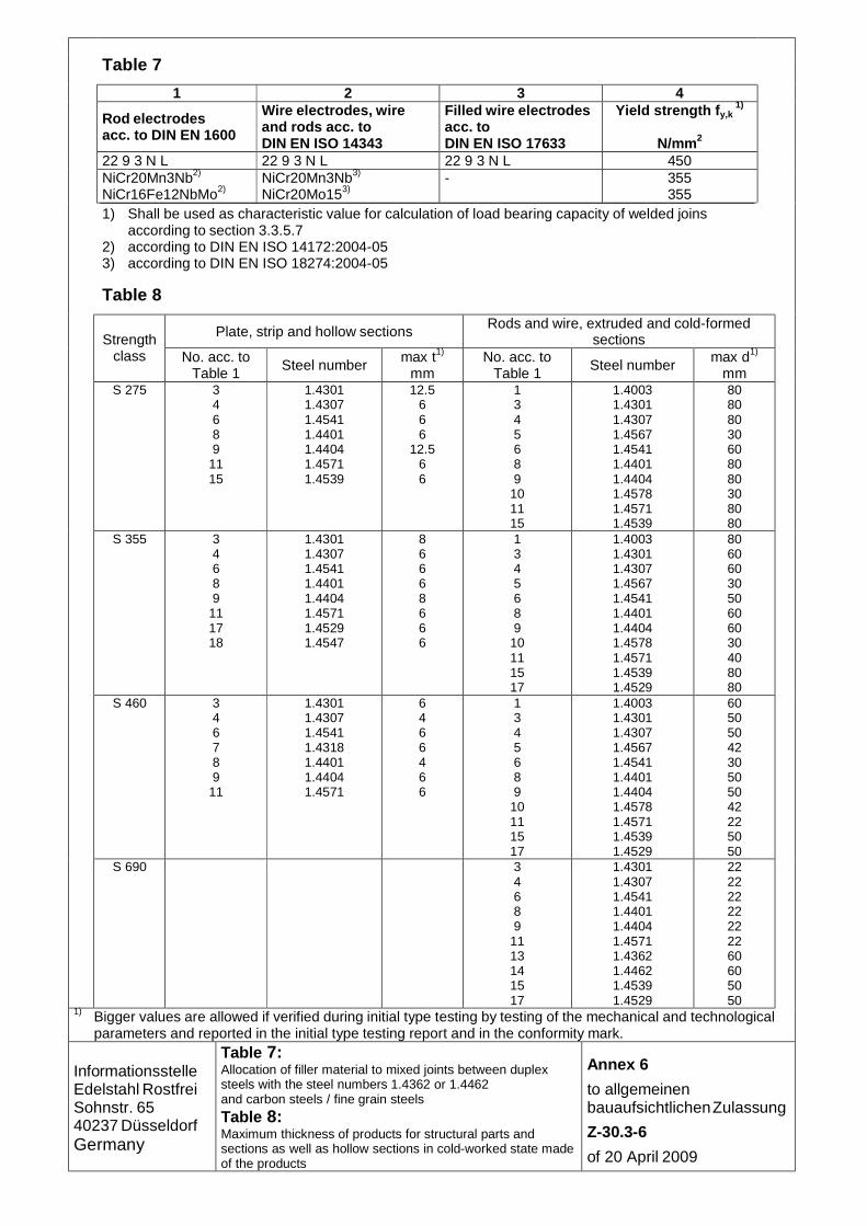
Table 7
1 2 3 4
Rod electrodes acc. to DIN EN 1600
Wire electrodes, wire and rods acc. to DIN EN ISO 14343
Filled wire electrodes acc. to DIN EN ISO 17633
Yield strength f y,k 1)
N/mm2
22 9 3 N L 22 9 3 N L 22 9 3 N L 450 NiCr20Mn3Nb2) NiCr16Fe12NbMo2)
NiCr20Mn3Nb3) NiCr20Mo153)
- 355 355
1) Shall be used as characteristic value for calculation of load bearing capacity of welded joins according to section 3.3.5.7
2) according to DIN EN ISO 14172:2004-05 3) according to DIN EN ISO 18274:2004-05
Table 8
Plate, strip and hollow sections Rods and wire, extruded and cold-formed sections Strength
class No. acc. to Table 1
Steel number max t1)
mm No. acc. to
Table 1 Steel number max d1)
mm S 275 3
4 6 8 9
11 15
1.4301 1.4307 1.4541 1.4401 1.4404 1.4571 1.4539
12.5 6 6 6
12.5 6 6
1 3 4 5 6 8 9
10 11 15
1.4003 1.4301 1.4307 1.4567 1.4541 1.4401 1.4404 1.4578 1.4571 1.4539
80 80 80 30 60 80 80 30 80 80
S 355 3 4 6 8 9
11 17 18
1.4301 1.4307 1.4541 1.4401 1.4404 1.4571 1.4529 1.4547
8 6 6 6 8 6 6 6
1 3 4 5 6 8 9
10 11 15 17
1.4003 1.4301 1.4307 1.4567 1.4541 1.4401 1.4404 1.4578 1.4571 1.4539 1.4529
80 60 60 30 50 60 60 30 40 80 80
S 460 3 4 6 7 8 9
11
1.4301 1.4307 1.4541 1.4318 1.4401 1.4404 1.4571
6 4 6 6 4 6 6
1 3 4 5 6 8 9
10 11 15 17
1.4003 1.4301 1.4307 1.4567 1.4541 1.4401 1.4404 1.4578 1.4571 1.4539 1.4529
60 50 50 42 30 50 50 42 22 50 50
S 690 3 4 6 8 9
11 13 14 15 17
1.4301 1.4307 1.4541 1.4401 1.4404 1.4571 1.4362 1.4462 1.4539 1.4529
22 22 22 22 22 22 60 60 50 50
1) Bigger values are allowed if verified during initial type testing by testing of the mechanical and technological parameters and reported in the initial type testing report and in the conformity mark.
Informationsstelle Edelstahl Rostfrei Sohnstr. 65 40237 Düsseldorf Germany
Table 7: Allocation of filler material to mixed joints between duplex steels with the steel numbers 1.4362 or 1.4462 and carbon steels / fine grain steels
Table 8: Maximum thickness of products for structural parts and sections as well as hollow sections in cold-worked state made of the products
Annex 6
to allgemeinen bauaufsichtlichen Zulassung
Z-30.3-6
of 20 April 2009

Table 9 Plate, strip and hollow sections Rods and wire, extruded and cold-
for med sections
No. acc. to Table 1
Steel number max t1)
mm No. acc. to
Table 1 Steel number
max t1)
mm
1 1.4003 12 1 1.4003 25 3
8 1.4301 1.4401
62) 3 8
1.4301 1.4401
252)
4 6 7 9
11
1.4307 1.4541 1.4318 1.4404 1.4571
30 4 6 7 9 11
1.4307 1.4541 1.4318 1.4404 1.4571
45
12 15 16 17 18
1.4439 1.4539 1.4565 1.4529 1.4547
12 12 15 16 17
1.4439 1.4539 1.4565 1.4529
25
13 14
1.4362 1.4462
30 13 14
1.4362 1.4462
45
1) For bigger thicknesses a welding procedure qualification for each thickness and kind of welded joint is required.
2) For bigger thicknesses the resistance against intergranular corrosion shall be proved
according to DIN EN ISO 3651.
Table 10
Structural parts in swimming pool atmospheres Steel grades
with regular cleaning of the structural parts Choice of corrosion resistance class according to Table 1a
without regular cleaning 1) of the structural parts in the area of water according to Trinkwasserverordnung2) (regulation for drinking water) Cl < 250 mg/l
1.4539 1.4565 1.4529 1.4547
without regular cleaning 1) of the structural parts in the area of chloride rich water2) (e.g. brine water), Cl > 250 mg/l
1.4565 1.4529 1.4547
1) see Merkblatt 831 "Edelstahl Rostfrei in Schwimmbädern (MB 831)" (Information sheet 831 “Stainless steels in swimming pools” (MB 831)) 2nd edition 2000 of Informationsstelle Edelstahl Rostfrei (information centre for stainless steels) 2) Splash water and aerosols shall be considered which may reach areas not accessible and not cleaned regularly e.g. via ventilation and leading there to high concentrations
Informationsstelle Edelstahl Rostfrei Sohnstr. 65 40237 Düsseldorf Germany
Table 9: Maximum thickness for welded structural parts Table 10: Steel grades for swimming pools
Annex 7
to allgemeinen bauaufsichtlichen Zulassung
Z-30.3-6
of 20 April 2009

1 2 3 4 5 6 7 8 9
Strength Steel Yield strengthTension
resistance E-Modulus, modulus of shear (G) Coefficient Density
class number structural parts1) welded joints2)for structural calculations of thermal
cold rolled strip3)
other cold rolled strip3)
other general4)
except by constraint stresses and proof of
stability acc. to section 3.3.2.3
constraint stresses
expansion
fy,k fu,k E E
G G
N/mm² N/mm² N/mm² N/mm² N/mm² 10-6 x K-1kg/dm³
S 235 1.4567 -- 175 -- -- 450 7.91.4578 8.01.4301 7.91.4307 220 190 220 1901.45411.4401 500 170 000 200 000 161.4404 240 200 240 2001.4571 65 400 76 900 8.01.4539 240 220 240 2201.4003 240 240 240 240 450 10 7.71.4016 -- 240 -- -- 400
S 275 1.43011.4307 275 275 2751.4541 7.91.4567 -- -- -- 170 000 200 000 161.45781.4401 5501.4404 275 275 275 275 65 400 76 9001.4571 8.01.45391.4003 -- -- 10 7.71.4439 290 290 275 16 8.01.4529 300 300 300 300 8.11.4547 275 -- 275 -- 600 17 8.0
S 355 1.4003 -- 355 -- 320 10 7.71.4318 350 330 350 3001.43011.4307 355 355 3551.4541 7.91.4567 -- -- -- 170 000 200 000 161.4578 355 6001.44011.4404 355 355 355 65 400 76 900 8.01.45711.4539 -- -- 3201.4529 355 8.11.4547 -- -- 17 8.0
Table 11
Annex 8.1a
to allgemeinen
bauaufsichtlichen Zulassung
Z-30.3-6
of 2 May 2011
Tab
le 11: C
haracteristic values for structural parts w
elded joints included
Informationsstelle
Edelstahl R
ostfrei S
ohnstr. 65 40237 D
üsseldorfG
ermany
fy,k
355355
Z20656.11
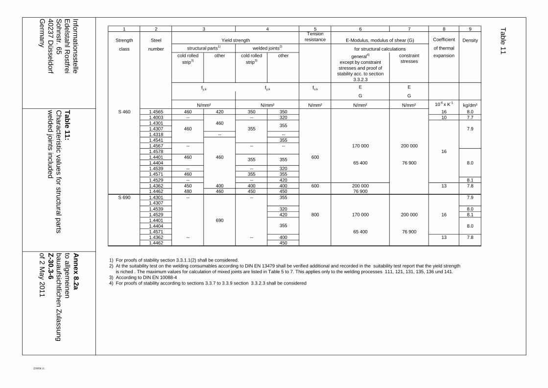
1 2 3 4 5 6 7 8 9
Strength Steel Yield strengthTension
resistance E-Modulus, modulus of shear (G) Coefficient Density
class number structural parts1) welded joints2)for structural calculations of thermal
cold rolled strip3)
other cold rolled strip3)
other general4)
except by constraint stresses and proof of
stability acc. to section 3.3.2.3
constraint stresses
expansion
fy,k fu,k E E
G G
N/mm² N/mm² N/mm² N/mm² N/mm² 10-6 x K-1kg/dm³
S 460 1.4565 460 420 350 350 16 8.01.4003 -- -- 320 10 7.71.4301 4601.4307 460 355 7.91.4318 -- --1.4541 3551.4567 -- -- -- 170 000 200 0001.4578 161.4401 460 460 6001.4404 65 400 76 900 8.01.4539 -- -- 3201.4571 460 355 3551.4529 -- -- 420 8.11.4362 450 400 400 400 600 200 000 13 7.81.4462 480 460 450 450 76 900
S 690 1.4301 -- -- 355 7.91.43071.4539 320 8.01.4529 420 800 170 000 200 000 16 8.11.4401 6901.4404 8.01.4571 65 400 76 9001.4362 -- -- 400 13 7.81.4462 450
Annex 8.2a
to allgemeinen
bauaufsichtlichen Zulassung
Z-30.3-6
of 2 May 2011
355
355
Table 11
Informationsstelle
Edelstahl R
ostfrei S
ohnstr. 65 40237 D
üsseldorfG
ermany
fy,k
355
355
Table 11:
Characteristic values for structural parts
welded joints included
1) For proofs of stability section 3.3.1.1(2) shall be considered. 2) At the suitability test on the welding consumables according to DIN EN 13479 shall be verified additional and recorded in the suitability test report that the yield strength is riched . The maximum values for calculation of mixed joints are listed in Table 5 to 7. This applies only to the welding processes 111, 121, 131, 135, 136 und 141.3) According to DIN EN 10088-44) For proofs of stability according to sections 3.3.7 to 3.3.9 section 3.3.2.3 shall be considered
Z20656.11
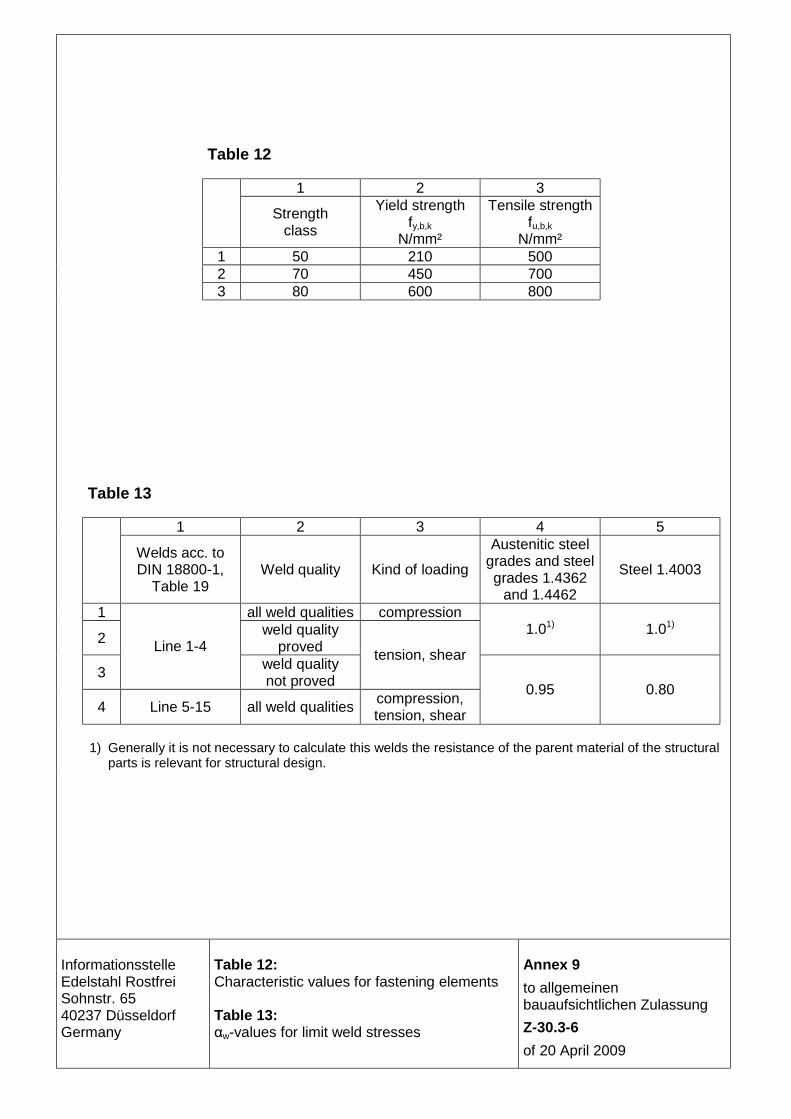
Table 12 1 2 3
Strength class
Yield strength fy,b,k
N/mm²
Tensile strength fu,b,k
N/mm²
1 50 210 500 2 70 450 700 3 80 600 800 Table 13
1 2 3 4 5
Welds acc. to DIN 18800-1,
Table 19 Weld quality Kind of loading
Austenitic steel grades and steel grades 1.4362
and 1.4462
Steel 1.4003
1 all weld qualities compression
2 weld quality proved
1.01) 1.01)
3
Line 1-4 weld quality not proved
tension, shear
4 Line 5-15 all weld qualities compression, tension, shear
0.95 0.80
1) Generally it is not necessary to calculate this welds the resistance of the parent material of the structural parts is relevant for structural design.
Informationsstelle Edelstahl Rostfrei Sohnstr. 65 40237 Düsseldorf Germany
Table 12: Characteristic values for fastening elements Table 13: αw-values for limit weld stresses
Annex 9
to allgemeinen bauaufsichtlichen Zulassung
Z-30.3-6
of 20 April 2009
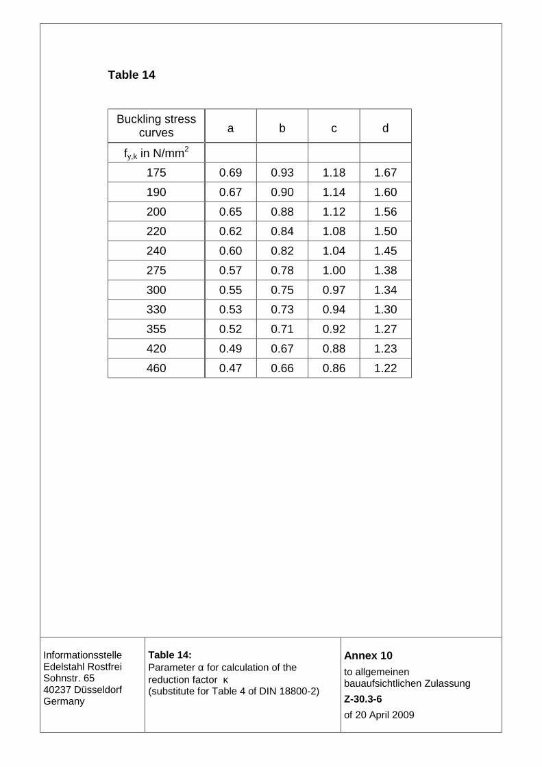
Table 14
Buckling stress curves a b c d
fy,k in N/mm2
175 0.69 0.93 1.18 1.67
190 0.67 0.90 1.14 1.60
200 0.65 0.88 1.12 1.56
220 0.62 0.84 1.08 1.50
240 0.60 0.82 1.04 1.45
275 0.57 0.78 1.00 1.38
300 0.55 0.75 0.97 1.34
330 0.53 0.73 0.94 1.30
355 0.52 0.71 0.92 1.27
420 0.49 0.67 0.88 1.23
460 0.47 0.66 0.86 1.22
Informationsstelle Edelstahl Rostfrei Sohnstr. 65 40237 Düsseldorf Germany
Table 14: Parameter α for calculation of the reduction factor κ (substitute for Table 4 of DIN 18800-2)
Annex 10
to allgemeinen bauaufsichtlichen Zulassung
Z-30.3-6
of 20 April 2009

1 1) 2 ...4 2) 5
3
1=κ for grenz,PP λ≤λ
)22.01
(c74.02PP λ
−λ
⋅⋅=κ for grenz,PP λ>λ
with 25.125.025.1c ≤ψ⋅−= and
5.0)c88.0cc( 2grenz,P ⋅⋅−+⋅η=λ
4
1=κ for grenz,PP λ≤λ
87.01.1
12P +λ⋅
=κ for grenz,PP λ>λ
with
η⋅=λ 7.0grenz,P
5
1=κ for grenz,PP λ≤λ
2PP
11.068.0
λ−
λ=κ for 6875.0Pgrenz,P <λ<λ
P
52.0
λ=κ for 6875.0P ≥λ
with
η⋅=λ 7.0grenz,P
6
1=κτ for grenz,PP λ≤λ
2PP
16.082.0
λ−
λ=κτ for 8.0Pgrenz,P <λ<λ
P
62.0
λ=κτ for 8.0P ≥λ
with
η⋅=λ 84.0grenz,P
7
1=κτ for grenz,PP λ≤λ
2PP
16.082.0
λ−
λ=κτ for 8.0Pgrenz,P <λ<λ
P
62.0
λ=κτ for 79.18,0 P ≤λ≤
2P
11.1
λ=κτ for 79.1P >λ
with
η⋅=λ 84.0grenz,P
E
E y,sek=η applies with Esek,y = secant modulus according to section 3.3.2.3.2(1)
E = elasticity modulus according to Table 11, line 6 1) Line 1 and 2 of Table 1 of DIN 18800-3:2008-11 do not apply because only unstiffened plates are considered. 2) The text of Table 1 of DIN 18800-3:2008-11 applies unchanged for column 2 to 4. Remark: fyk shall be taken from Table 11, column 3 under attention of section 3.3.1.1(2), σpi and τPi shall be calculated with σe according to section 3.3.8.2.
Informationsstelle Edelstahl Rostfrei Sohnstr. 65 40237 Düsseldorf Germany
Table 15: reducing factor κ (= related bearing buckling stress) at single effect of σx, σy or τ
Annex 11
to allgemeinen bauaufsichtlichen Zulassung
Z-30.3-6
of 20 April 2009

Table 16
Line Range of validity
1
d ≤ 150mm
h ≤ 340mm
b ≤ 340mm
2 0.5 ≤ h/b ≤ 2.0
3 1.5mm ≤ t ≤ 15mm
4 d/t ≤ 35
b/t ≤ 35 Table 17
Range of validity
Line with without
stiffening plate
b ≤ 340mm b ≤ 240mm 1
h ≤ 340mm h ≤ 240mm
2 0.33 ≤ h/b ≤ 3.5
3 2.5mm ≤ t ≤ 15mm
4 b/t ≤ 26 ; h/t ≤ 26
Informationsstelle Edelstahl Rostfrei Sohnstr. 65 40237 Düsseldorf Germany
Table 16: Limits and conditions for member dimensions in lattice girder made of hollow sections Table 17: Limits and conditions for member dimensions in bending rigid stiff-jointed framework with ϑ = 90° and with mitre joint
Annex 12
to allgemeinen bauaufsichtlichen Zulassung
Z-30.3-6
of 20 April 2009

In the 22 Tables of this Annex, the characteristic values of the real buckling stresses σS,R,k according to DIN 18800-4 Element 203 are indicated in dependence on the shell slenderness sλ that shall be determined according to DIN 18800-4 Element 203 using the values E und fy,k according to section 3.3.9.2.
1. For normal cases of shell buckling susceptible to imperfection, the tables for which κ1 is indicated in the upper left corner in brackets apply according to the equations 7 in
Element 204. For shell slendernesses 00.2≥sλ , equation 7c in DIN 18800-4 Element 204 applies using the values E and fy,k according to section 3.3.9.2 of this approval.
If the value σS,R,k/fy.k determined with the tabular values is smaller than the value Ψ κ2, determined for the same value Ψ according to section 3.3.9.4, the value Ψ κ2 fy,k may be set as characteristic value of the real buckling stress.
2. For cases of shell buckling very susceptible to imperfection according to the equations 8 in Element 204 – unless it does not concern the cylindrical shell with compressive load in axial direction treated in section 3.3.9.4 – those tables apply for which κ2 is indicated in the upper left corner in brackets. .
a) For shell slendernesses 58.135.1 <≤ sλ equation 8b applies, in which sλ shall be
substituted by sλ4.0 . When determining the characteristic values of the real
buckling stresses σS,R,k according to Element 203 of DIN 18800-4, the value fy,k shall be substituted by 0.4fy,k as well.
b) For shell slendernesses 37.258.1 <≤ sλ equation 8c applies, in which sλ shall be
substituted by sλ4.0 . When determining the characteristic values of the real
buckling stresses σS,R,k according to Element 203 of DIN 18800-4, the value fy,k shall be substituted by 0.4fy,k as well. In this case, a higher characteristic value of the real buckling stress ensues, if instead of the yield strength specified for the steel according to Table 11 and section 3.3.1.1(2), a reduced value of fy,k
* = 2.5σSi is set, with the ideal buckling stress σSi. fy,k
* ≥ 190N/mm2 shall be kept.
c) For shell slendernesses sλ≤37.2 equation 8d according to Element 204 of DIN 18800-4 applies.
In the cases 2a) to 2c) the values E and fy,k according to section 3.3.9.2.
From the values given in the Tables or the characteristic values of the real buckling stress determined with the previously mentioned formulae beyond the range of values of the Tables, the design values σS,R,d with the partial safety factors of the resistances shall be determined according to the equations 12 and 13 in Element 206 of DIN 18800-4.
When determining the real buckling stress under shear stress, fy,k / 3 shall be applied instead of fy,k, and the Tables as well as the above regulations apply for normal cases of shell buckling (κ1) susceptible to imperfection.
Informationsstelle Edelstahl Rostfrei Sohnstr. 65 40237 Düsseldorf Germany
Characteristic values of the real buckling stresses σS,R,k according to DIN 18800-4, Element 203
Anlage 13
zur allgemeinen bauaufsichtlichen Zulassung
Z-30.3-6
vom 20. April 2009
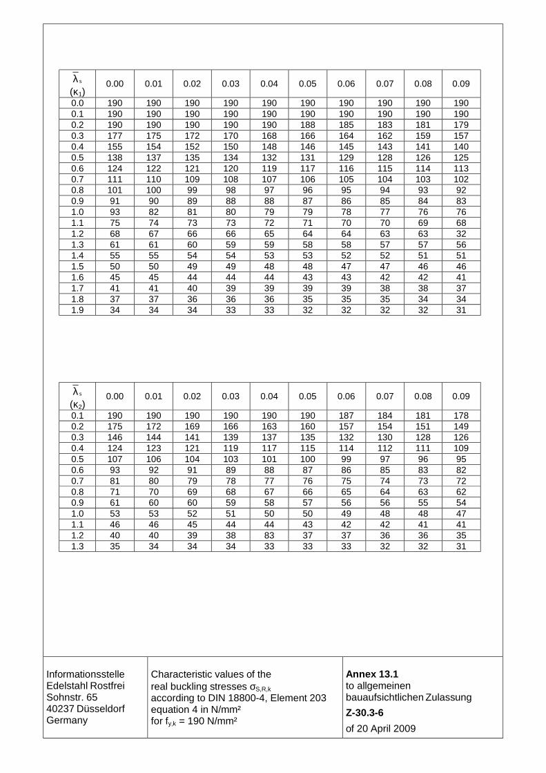
sλ (κ1)
0.00 0.01 0.02 0.03 0.04 0.05 0.06 0.07 0.08 0.09
0.0 190 190 190 190 190 190 190 190 190 190 0.1 190 190 190 190 190 190 190 190 190 190 0.2 190 190 190 190 190 188 185 183 181 179 0.3 177 175 172 170 168 166 164 162 159 157 0.4 155 154 152 150 148 146 145 143 141 140 0.5 138 137 135 134 132 131 129 128 126 125 0.6 124 122 121 120 119 117 116 115 114 113 0.7 111 110 109 108 107 106 105 104 103 102 0.8 101 100 99 98 97 96 95 94 93 92 0.9 91 90 89 88 88 87 86 85 84 83 1.0 93 82 81 80 79 79 78 77 76 76 1.1 75 74 73 73 72 71 70 70 69 68 1.2 68 67 66 66 65 64 64 63 63 32 1.3 61 61 60 59 59 58 58 57 57 56 1.4 55 55 54 54 53 53 52 52 51 51 1.5 50 50 49 49 48 48 47 47 46 46 1.6 45 45 44 44 44 43 43 42 42 41 1.7 41 41 40 39 39 39 39 38 38 37 1.8 37 37 36 36 36 35 35 35 34 34 1.9 34 34 34 33 33 32 32 32 32 31
sλ (κ2)
0.00 0.01 0.02 0.03 0.04 0.05 0.06 0.07 0.08 0.09
0.1 190 190 190 190 190 190 187 184 181 178 0.2 175 172 169 166 163 160 157 154 151 149 0.3 146 144 141 139 137 135 132 130 128 126 0.4 124 123 121 119 117 115 114 112 111 109 0.5 107 106 104 103 101 100 99 97 96 95 0.6 93 92 91 89 88 87 86 85 83 82 0.7 81 80 79 78 77 76 75 74 73 72 0.8 71 70 69 68 67 66 65 64 63 62 0.9 61 60 60 59 58 57 56 56 55 54 1.0 53 53 52 51 50 50 49 48 48 47 1.1 46 46 45 44 44 43 42 42 41 41 1.2 40 40 39 38 83 37 37 36 36 35 1.3 35 34 34 34 33 33 33 32 32 31
Informationsstelle Edelstahl Rostfrei Sohnstr. 65 40237 Düsseldorf Germany
Characteristic values of the real buckling stresses σS,R,k according to DIN 18800-4, Element 203 equation 4 in N/mm² for fy,k = 190 N/mm²
Ann ex 13.1 to allgemeinen bauaufsichtlichen Zulassung
Z-30.3-6
of 20 April 2009

sλ (κ1)
0.00 0.01 0.02 0.03 0.04 0.05 0.06 0.07 0.08 0.09
0.0 200 200 200 200 200 200 200 200 200 200 0.1 200 200 200 200 200 200 200 200 200 200 0.2 200 200 200 200 200 198 196 194 192 189 0.3 187 185 183 180 178 176 174 171 169 167 0.4 165 163 161 159 157 155 153 152 150 148 0.5 146 145 143 142 140 138 137 135 134 133 0.6 131 130 128 127 126 124 123 122 121 119 0.7 118 117 116 115 113 112 111 110 109 108 0.8 107 106 105 103 102 101 100 99 98 97 0.9 96 96 95 94 93 92 91 90 89 88 1.0 87 86 86 85 84 83 82 81 81 80 1.1 79 78 78 77 76 75 74 74 73 72 1.2 72 71 70 69 69 68 67 67 66 65 1.3 65 64 63 63 62 62 61 60 60 59 1.4 59 58 57 57 56 56 55 55 54 53 1.5 53 52 52 51 51 50 50 49 49 48 1.6 48 47 47 46 46 45 45 45 44 44 1.7 43 43 42 42 41 41 41 40 40 39 1.8 39 39 38 38 38 38 37 36 36 36 1.9 36 36 35 35 35 34 34 33 33 33
sλ (κ2)
0.00 0.01 0.02 0.03 0.04 0.05 0.06 0.07 0.08 0.09
0.1 200 200 200 200 200 200 198 194 191 188 0.2 185 182 179 176 173 170 166 163 161 158 0.3 155 152 150 147 145 143 140 138 136 134 0.4 132 130 128 126 124 122 121 119 117 115 0.5 114 112 111 109 107 106 104 103 102 100 0.6 99 97 96 95 93 92 91 89 88 87 0.7 86 85 83 82 81 80 79 78 77 76 0.8 75 74 73 72 71 70 69 68 67 66 0.9 65 64 63 62 61 60 60 59 58 57 1.0 56 55 55 54 53 52 52 51 50 49 1.1 49 48 47 47 46 45 45 44 44 43 1.2 42 42 41 41 40 39 39 38 38 37 1.3 37 36 36 35 35 35 34 34 33 33
Informationsstelle Edelstahl Rostfrei Sohnstr. 65 40237 Düsseldorf Germany
Characteristic values of the real buckling stresses σS,R,k according to DIN 18800-4, Element 203 equation 4 in N/mm² for fy,k = 200 N/mm²
Ann ex 13.2 to allgemeinen bauaufsichtlichen Zulassung
Z-30.3-6
of 20 April 2009

sλ (κ1)
0.00 0.01 0.02 0.03 0.04 0.05 0.06 0.07 0.08 0.09
0.0 220 220 220 220 220 220 220 220 220 220 0.1 220 220 220 220 220 220 220 220 220 220 0.2 220 220 220 220 220 220 218 215 213 210 0.3 208 206 203 201 198 196 194 191 189 186 0.4 184 182 179 177 175 173 171 169 167 165 0.5 163 161 160 158 156 154 153 151 149 148 0.6 146 145 143 142 140 139 137 136 134 133 0.7 131 130 129 127 126 125 124 122 121 120 0.8 119 117 116 115 114 113 112 111 109 108 0.9 107 106 105 104 103 102 101 100 99 98 1.0 97 96 95 94 93 92 91 90 90 89 1.1 88 87 86 85 84 83 83 82 81 80 1.2 79 79 78 77 76 75 75 74 73 72 1.3 72 71 70 70 69 68 67 67 66 65 1.4 65 64 63 63 62 61 61 60 60 59 1.5 58 58 57 57 56 56 55 54 54 53 1.6 53 52 52 51 51 50 50 49 49 48 1.7 48 47 47 46 46 45 45 44 44 43 1.8 43 43 42 42 41 41 41 40 40 40 1.9 40 39 39 38 38 38 37 37 36 36
sλ (κ2)
0.00 0.01 0.02 0.03 0.04 0.05 0.06 0.07 0.08 0.09
0.1 220 220 220 220 220 220 219 216 212 209 0.2 206 202 199 196 193 189 186 182 179 176 0.3 173 170 167 164 162 159 157 154 152 149 0.4 147 145 143 141 138 136 134 132 130 129 0.5 127 125 123 121 120 118 116 115 113 111 0.6 110 108 107 105 104 102 101 99 98 97 0.7 95 94 93 91 90 89 88 86 85 84 0.8 83 82 80 79 78 77 76 75 74 73 0.9 72 71 70 69 68 67 66 65 64 63 1.0 62 61 60 60 59 58 57 56 55 55 1.1 54 53 52 52 51 50 49 49 48 47 1.2 47 46 45 45 44 43 43 42 42 41 1.3 41 40 39 39 38 38 38 37 37 36
Informationsstelle Edelstahl Rostfrei Sohnstr. 65 40237 Düsseldorf Germany
Characteristic values of the real buckling stresses σS,R,k according to DIN 18800-4, Element 203 equation 4 in N/mm² for fy,k = 220 N/mm²
Ann ex 13.3 to allgemeinen bauaufsichtlichen Zulassung
Z-30.3-6
of 20 April 2009

sλ (κ1)
0.00 0.01 0.02 0.03 0.04 0.05 0.06 0.07 0.08 0.09
0.0 240 240 240 240 240 240 240 240 240 240 0.1 240 240 240 240 240 240 240 240 240 240 0.2 240 240 240 240 240 240 239 237 234 232 0.3 229 226 224 221 219 216 214 211 209 206 0.4 203 201 198 196 194 191 189 187 185 182 0.5 180 178 176 174 172 170 169 167 165 163 0.6 161 160 158 156 155 153 151 150 148 147 0.7 145 144 142 141 139 138 136 135 134 132 0.8 131 129 128 127 126 124 123 122 121 119 0.9 118 117 116 115 113 112 111 110 109 108 1.0 107 106 105 104 103 101 100 99 98 97 1.1 96 95 95 94 93 92 91 90 89 88 1.2 87 86 85 84 84 83 82 81 80 79 1.3 79 78 77 76 75 75 74 73 72 72 1.4 71 70 70 69 68 67 67 66 65 65 1.5 64 63 63 62 61 61 60 60 59 58 1.6 58 57 57 56 55 55 54 54 53 53 1.7 52 52 51 51 50 49 49 48 48 48 1.8 47 47 46 46 45 45 44 44 43 43 1.9 43 43 42 42 41 41 41 40 40 39
sλ (κ2)
0.00 0.01 0.02 0.03 0.04 0.05 0.06 0.07 0.08 0.09
0.1 240 240 240 240 240 240 240 237 233 230 0.2 226 223 219 216 212 209 206 202 198 195 0.3 191 188 185 182 179 176 173 170 168 165 0.4 162 160 157 155 153 150 148 146 144 142 0.5 140 138 136 134 132 130 128 126 124 123 0.6 121 119 118 116 114 113 111 109 108 106 0.7 105 103 102 100 99 98 96 95 94 92 0.8 91 90 88 87 86 85 83 82 81 80 0.9 79 78 77 75 74 73 72 71 70 69 1.0 68 67 66 65 64 63 63 62 61 60 1.1 59 58 57 56 56 55 54 53 53 52 1.2 51 50 50 49 48 48 47 46 46 45 1.3 44 44 43 42 42 42 41 41 40 40
Informationsstelle Edelstahl Rostfrei Sohnstr. 65 40237 Düsseldorf Germany
Characteristic values of the real buckling stresses σS,R,k according to DIN 18800-4, Element 203 equation 4 in N/mm² for fy,k = 240 N/mm²
Ann ex 13.4 to allgemeinen bauaufsichtlichen Zulassung
Z-30.3-6
of 20 April 2009

sλ (κ1)
0.00 0.01 0.02 0.03 0.04 0.05 0.06 0.07 0.08 0.09
0.0 275 275 275 275 275 275 275 275 275 275 0.1 275 275 275 275 275 275 275 275 275 275 0.2 275 275 275 275 275 275 275 274 271 269 0.3 266 263 260 257 254 252 249 246 243 240 0.4 238 235 232 229 226 224 221 218 216 213 0.5 211 208 206 204 201 199 197 195 192 190 0.6 188 186 184 182 180 178 176 175 173 171 0.7 169 167 166 164 162 160 159 157 155 154 0.8 152 151 149 148 146 145 143 142 140 139 0.9 137 136 135 133 132 130 129 128 127 125 1.0 124 123 121 120 119 118 117 115 114 113 1.1 112 111 110 108 107 106 105 104 103 102 1.2 101 100 99 98 97 96 95 94 93 92 1.3 91 90 89 88 87 86 85 85 84 83 1.4 82 81 80 79 79 78 77 76 75 75 1.5 74 73 72 71 71 70 69 69 68 67 1.6 66 66 65 64 64 63 62 62 61 60 1.7 60 59 59 58 57 57 56 56 55 55 1.8 54 54 53 53 52 51 51 50 50 50 1.9 50 49 48 48 47 47 47 46 46 45
sλ (κ2)
0.00 0.01 0.02 0.03 0.04 0.05 0.06 0.07 0.08 0.09
0.1 275 275 275 275 275 275 275 274 270 266 0.2 262 258 255 251 247 243 239 235 232 227 0.3 223 220 216 212 209 205 202 199 196 193 0.4 190 187 184 181 178 176 173 170 168 165 0.5 163 160 158 156 154 151 149 147 145 143 0.6 141 139 137 135 133 131 129 127 125 124 0.7 122 120 118 117 115 113 112 110 109 107 0.8 105 104 102 101 99 98 97 95 94 93 0.9 91 90 89 87 86 85 83 82 81 80 1.0 79 78 76 75 74 73 72 71 70 69 1.1 68 67 66 65 64 63 62 61 60 60 1.2 59 58 57 56 55 55 54 53 52 52 1.3 51 50 49 49 48 48 47 47 46 45
Informationsstelle Edelstahl Rostfrei Sohnstr. 65 40237 Düsseldorf Germany
Characteristic values of the real buckling stresses σS,R,k according to DIN 18800-4, Element 203 equation 4 in N/mm² for fy,k = 275 N/mm²
Ann ex 13.5 to allgemeinen bauaufsichtlichen Zulassung
Z-30.3-6
of 20 April 2009

sλ (κ1)
0.00 0.01 0.02 0.03 0.04 0.05 0.06 0.07 0.08 0.09
0.0 290 290 290 290 290 290 290 290 290 290 0.1 290 290 290 290 290 290 290 290 290 290 0.2 290 290 290 290 290 290 290 290 287 284 0.3 281 279 276 273 270 267 264 261 258 255 0.4 252 249 246 243 240 238 235 232 229 226 0.5 224 221 219 216 214 211 209 207 204 202 0.6 200 198 196 193 191 198 187 185 183 181 0.7 179 178 176 174 172 170 168 167 165 163 0.8 162 160 158 157 155 153 152 150 149 147 0.9 146 144 143 141 140 138 137 136 134 133 1.0 131 130 129 127 126 125 123 122 121 120 1.1 118 117 116 115 114 113 111 110 109 108 1.2 107 106 105 104 102 101 100 99 98 97 1.3 96 95 94 93 92 91 90 89 88 88 1.4 87 86 85 84 83 82 81 80 80 79 1.5 78 77 76 76 75 74 73 72 72 71 1.6 70 69 69 68 67 67 66 65 65 64 1.7 63 63 62 61 61 60 59 59 58 58 1.8 57 57 56 55 55 54 54 53 53 52 1.9 52 52 51 51 50 50 49 49 48 48
sλ (κ2)
0.00 0.01 0.02 0.03 0.04 0.05 0.06 0.07 0.08 0.09
0.1 290 290 290 290 290 290 290 290 286 282 0.2 278 274 270 266 262 258 254 250 246 242 0.3 238 233 229 226 222 218 215 211 208 205 0.4 201 198 195 192 189 186 184 181 178 176 0.5 173 170 168 165 163 161 158 156 154 151 0.6 149 147 145 143 141 139 137 135 133 131 0.7 129 127 125 124 122 120 118 117 115 113 0.8 112 110 108 107 105 104 103 101 99 98 0.9 96 95 94 92 91 90 88 87 86 84 1.0 83 82 81 80 78 77 76 75 74 73 1.1 72 71 70 69 68 67 66 65 64 63 1.2 62 61 60 59 58 58 57 56 55 54 1.3 54 53 52 51 51 51 50 49 49 48
Informationsstelle Edelstahl Rostfrei Sohnstr. 65 40237 Düsseldorf Germany
Characteristic values of the real buckling stresses σS,R,k according to DIN 18800-4, Element 203 equation 4 in N/mm² for fy,k = 290 N/mm²
Ann ex 13.6 to allgemeinen bauaufsichtlichen Zulassung
Z-30.3-6
of 20 April 2009

sλ (κ1)
0.00 0.01 0.02 0.03 0.04 0.05 0.06 0.07 0.08 0.09
0.0 300 300 300 300 300 300 300 300 300 300 0.1 300 300 300 300 300 300 300 300 300 300 0.2 300 300 300 300 300 300 300 300 298 295 0.3 292 289 286 283 280 277 274 271 268 265 0.4 262 259 256 253 250 247 244 241 238 235 0.5 233 230 227 225 222 220 217 215 212 210 0.6 208 206 203 201 199 197 195 193 190 188 0.7 186 185 183 181 179 177 175 173 171 170 0.8 168 166 164 163 161 159 158 156 154 153 0.9 151 150 148 147 145 144 142 141 139 138 1.0 136 135 134 132 131 129 128 127 126 124 1.1 123 122 120 119 118 117 115 114 113 112 1.2 111 110 108 107 106 105 104 103 102 101 1.3 100 99 98 97 96 95 94 93 92 91 1.4 90 89 88 87 86 85 84 83 82 82 1.5 81 80 79 78 77 77 76 75 74 73 1.6 73 72 71 70 70 69 68 68 67 66 1.7 65 65 64 63 63 62 62 61 60 60 1.8 59 58 58 57 57 56 56 55 54 54 1.9 54 53 53 52 52 51 51 50 50 49
sλ (κ2)
0.00 0.01 0.02 0.03 0.04 0.05 0.06 0.07 0.08 0.09
0.1 300 300 300 300 300 300 300 300 296 292 0.2 288 286 280 276 272 268 264 260 255 251 0.3 247 243 239 235 231 227 223 220 216 213 0.4 209 206 203 200 197 194 191 188 185 182 0.5 180 177 174 172 169 167 164 162 160 157 0.6 155 153 151 148 146 144 142 140 138 136 0.7 134 132 130 128 126 152 123 121 119 118 0.8 116 114 113 111 109 108 106 105 103 102 0.9 100 99 97 96 94 93 92 90 89 88 1.0 86 85 84 83 81 80 79 78 77 75 1.1 74 73 72 71 70 69 68 67 66 65 1.2 64 63 62 61 61 60 59 58 57 56 1.3 56 55 54 53 53 52 52 51 50 50
Informationsstelle Edelstahl Rostfrei Sohnstr. 65 40237 Düsseldorf Germany
Characteristic values of the real buckling stresses σS,R,k according to DIN 18800-4, Element 203 equation 4 in N/mm² for fy,k = 300 N/mm²
Ann ex 13.7 to allgemeinen bauaufsichtlichen Zulassung
Z-30.3-6
of 20 April 2009

sλ (κ1)
0.00 0.01 0.02 0.03 0.04 0.05 0.06 0.07 0.08 0.09
0.0 330 330 330 330 330 330 330 330 330 330 0.1 330 330 330 330 330 330 330 330 330 330 0.2 330 330 330 330 330 330 330 330 330 327 0.3 324 320 317 314 311 308 304 301 298 295 0.4 291 288 285 282 278 275 272 269 266 262 0.5 259 256 253 251 248 245 242 239 237 234 0.6 231 229 226 224 222 219 217 214 212 210 0.7 208 205 203 201 199 197 195 193 191 189 0.8 187 185 183 181 179 177 175 173 172 170 0.9 168 166 165 163 161 160 158 156 155 153 1.0 151 150 148 147 145 144 142 141 139 138 1.1 136 135 133 132 131 129 128 127 125 124 1.2 123 121 120 119 118 116 115 114 113 112 1.3 110 109 108 107 106 105 104 102 101 100 1.4 99 98 97 96 95 94 93 92 91 90 1.5 89 88 87 86 85 85 84 83 82 81 1.6 80 79 78 78 77 75 75 74 74 73 1.7 72 71 71 70 69 68 68 67 66 66 1.8 65 65 64 63 63 62 61 61 60 59 1.9 59 59 58 58 57 56 56 55 55 54
sλ (κ2)
0.00 0.01 0.02 0.03 0.04 0.05 0.06 0.07 0.08 0.09
0.1 330 330 330 330 330 330 330 330 328 324 0.2 319 315 310 306 302 297 293 288 284 280 0.3 275 271 266 262 257 253 249 245 241 237 0.4 233 230 226 223 219 216 212 209 206 203 0.5 200 198 194 191 188 186 183 180 178 175 0.6 171 170 167 165 163 160 158 156 153 151 0.7 149 147 145 142 140 138 136 134 132 130 0.8 128 127 125 123 121 119 118 116 114 112 0.9 111 109 107 106 104 103 101 100 98 97 1.0 95 94 93 91 90 88 87 86 85 83 1.1 82 81 80 78 77 76 75 74 73 72 1.2 71 70 69 68 67 66 65 64 63 62 1.3 61 60 59 59 58 58 57 56 55 54
Informationsstelle Edelstahl Rostfrei Sohnstr. 65 40237 Düsseldorf Germany
Characteristic values of the real buckling stresses σS,R,k according to DIN 18800-4, Element 203 equation 4 in N/mm² for fy,k = 330 N/mm²
Ann ex 13.8 to allgemeinen bauaufsichtlichen Zulassung
Z-30.3-6
of 20 April 2009

sλ (κ1)
0.00 0.01 0.02 0.03 0.04 0.05 0.06 0.07 0.08 0.09
0.0 355 355 355 355 355 355 355 355 355 355 0.1 355 355 355 355 355 355 355 355 355 355 0.2 355 355 355 355 355 355 355 355 353 350 0.3 347 343 340 336 333 330 326 323 319 316 0.4 313 309 306 302 299 296 292 289 285 282 0.5 279 275 272 269 266 263 260 257 254 251 0.6 249 246 243 241 238 235 233 230 228 225 0.7 223 221 218 216 214 211 209 207 205 202 0.8 200 198 196 194 192 190 188 186 184 182 0.9 180 178 177 175 173 171 169 167 166 164 1.0 162 161 159 157 156 154 152 151 149 148 1.1 146 144 143 141 140 138 137 136 134 133 1.2 131 130 129 127 126 124 123 122 121 119 1.3 118 117 115 114 113 112 111 109 108 107 1.4 106 105 104 103 102 100 99 98 97 96 1.5 95 94 93 92 91 90 89 88 87 96 1.6 86 85 84 83 82 81 80 79 79 78 1.7 77 76 75 75 74 73 72 72 71 70 1.8 70 69 68 67 67 66 65 65 64 64 1.9 64 63 63 62 61 61 60 59 59 58
sλ (κ2)
0.00 0.01 0.02 0.03 0.04 0.05 0.06 0.07 0.08 0.09
0.1 355 355 355 355 355 355 355 355 354 350 0.2 345 340 336 331 326 322 317 313 308 303 0.3 299 294 289 284 280 275 270 266 262 258 0.4 253 249 246 242 238 234 231 227 224 220 0.5 217 214 211 207 206 201 195 195 193 190 0.6 187 184 181 179 176 174 171 169 166 164 0.7 161 159 157 154 152 150 148 145 143 141 0.8 139 137 135 133 131 129 127 125 123 122 0.9 120 118 116 114 113 111 109 108 106 105 1.0 103 101 100 98 97 95 94 93 91 90 1.1 89 87 86 85 83 82 81 80 79 77 1.2 76 75 74 73 72 71 70 69 68 67 1.3 66 65 64 64 63 62 61 60 59 59
Informationsstelle Edelstahl Rostfrei Sohnstr. 65 40237 Düsseldorf Germany
Characteristic values of the real buckling stresses σS,R,k according to DIN 18800-4, Element 203 equation 4 in N/mm² for fy,k = 355 N/mm²
Ann ex 13.9 to allgemeinen bauaufsichtlichen Zulassung
Z-30.3-6
of 20 April 2009

sλ (κ1)
0.00 0.01 0.02 0.03 0.04 0.05 0.06 0.07 0.08 0.09
0.0 420 420 420 420 420 420 420 420 420 420 0.1 420 420 420 420 420 420 420 420 420 420 0.2 420 420 420 420 420 420 420 420 420 420 0.3 419 415 411 407 403 399 396 392 388 384 0.4 380 376 362 368 365 361 357 353 349 345 0.5 341 337 334 330 326 322 318 315 311 308 0.6 304 301 297 294 291 288 284 281 278 275 0.7 272 269 266 263 261 258 255 252 250 247 0.8 244 242 239 236 234 231 229 227 224 222 0.9 219 217 215 212 210 208 206 204 201 199 1.0 197 195 193 191 189 187 185 183 181 179 1.1 177 175 173 171 170 168 166 164 162 161 1.2 159 157 155 154 152 150 149 147 146 144 1.3 143 141 139 138 136 135 133 132 131 129 1.4 128 126 125 124 122 121 120 118 117 116 1.5 115 113 112 111 110 108 107 106 105 104 1.6 103 102 101 99 98 97 96 95 94 93 1.7 92 91 90 89 89 88 87 86 85 84 1.8 83 836 82 81 80 79 78 77 77 76 1.9 76 75 74 73 73 72 71 70 70 69
sλ (κ2)
0.00 0.01 0.02 0.03 0.04 0.05 0.06 0.07 0.08 0.09
0.1 420 420 420 420 420 420 420 420 420 418 0.2 412 407 402 397 391 386 381 376 370 365 0.3 360 351 349 344 339 333 328 322 317 312 0.4 307 302 297 292 288 283 279 275 270 266 0.5 265 258 254 250 247 243 239 236 232 229 0.6 225 222 219 215 212 209 206 203 200 197 0.7 194 191 188 185 182 180 177 174 172 169 0.8 167 164 162 159 157 155 152 150 148 145 0.9 143 141 139 137 135 133 131 129 127 125 1.0 123 121 119 117 115 114 112 110 109 107 1.1 105 104 102 101 99 98 96 95 93 92 1.2 90 89 88 87 85 84 83 82 80 79 1.3 78 77 76 75 74 73 72 71 70 69
Informationsstelle Edelstahl Rostfrei Sohnstr. 65 40237 Düsseldorf Germany
Characteristic values of the real buckling stresses σS,R,k according to DIN 18800-4, Element 203 equation 4 in N/mm² for fy,k = 420 N/mm²
Ann ex 13.10 to allgemeinen bauaufsichtlichen Zulassung
Z-30.3-6
of 20 April 2009

sλ (κ1)
0.00 0.01 0.02 0.03 0.04 0.05 0.06 0.07 0.08 0.09
0.0 460 460 460 460 460 460 460 460 460 460 0.1 460 460 460 460 460 460 460 460 460 460 0.2 460 460 460 460 460 460 460 460 460 460 0.3 460 457 453 449 445 440 436 432 428 424 0.4 420 415 411 407 403 399 395 390 386 382 0.5 378 374 370 365 361 357 353 349 345 341 0.6 337 333 330 326 322 319 315 312 308 305 0.7 302 298 295 292 289 285 282 279 276 273 0.8 270 267 264 262 259 256 253 251 248 245 0.9 243 240 237 235 232 230 227 225 222 220 1.0 218 215 213 211 208 206 204 202 200 197 1.1 195 193 191 189 187 185 183 181 179 177 1.2 175 173 171 169 168 166 164 162 160 159 1.3 157 155 154 152 150 149 147 145 144 142 1.4 141 139 137 136 134 133 132 130 129 127 1.5 126 124 123 122 120 119 118 117 115 114 1.6 113 112 110 109 108 107 016 105 103 102 1.7 101 100 99 98 97 96 95 94 93 92 1.8 91 91 89 89 88 87 86 85 84 83 1.9 83 82 81 80 79 79 78 77 76 76
sλ (κ2)
0.00 0.01 0.02 0.03 0.04 0.05 0.06 0.07 0.08 0.09
0.1 460 460 460 460 460 460 460 460 460 460 0.2 454 448 443 437 431 426 420 414 409 403 0.3 397 392 386 380 375 369 363 357 351 346 0.4 340 335 329 324 319 314 309 304 300 295 0.5 290 286 282 277 273 269 265 261 257 253 0.6 249 245 242 238 235 231 228 224 221 217 0.7 214 211 208 205 201 198 195 192 190 187 0.8 184 181 178 176 173 170 168 165 163 160 0.9 158 155 153 151 148 146 144 141 139 137 1.0 135 133 131 129 127 125 123 121 119 117 1.1 116 114 112 110 109 107 105 104 102 101 1.2 99 98 96 95 94 92 91 89 88 87 1.3 86 84 83 82 81 80 79 78 77 76
Informationsstelle Edelstahl Rostfrei Sohnstr. 65 40237 Düsseldorf Germany
Characteristic values of the real buckling stresses σS,R,k according to DIN 18800-4, Element 203 equation 4 in N/mm² for fy,k = 460 N/mm²
Ann ex 13.11 to allgemeinen bauaufsichtlichen Zulassung
Z-30.3-6
of 20 April 2009

a)
E
Rp0,2
σ
ε
b)
E
fy,k
ε
σ
c)
fy,k
Esek,y
σ
ε
d)
fy,k
red fy,k
Esek
σ
ε
Informationsstelle Edelstahl Rostfrei Sohnstr. 65 40237 Düsseldorf Germany
Figure 1 stress-strain curves for stainless steels
a reality with non-linear elastic range approximated by power law
b,c,d bi-linear approximation
Annex 14
to allgemeinen bauaufsichtlichen Zulassung
Z-30.3-6
of 20 April 2009

buckling stress curve a
kλ 0.00 0.01 0.02 0.03 0.04 0.05 0.06 0.07 0.08 0.09
0.4 1.00 1.00 1.00 1.00 1.00 0.99 0.98 0.97 0.96 0.95
0.5 0.95 0.94 0.93 0.92 0.92 0.91 0.90 0.90 0.89 0.88
0.6 0.88 0.87 0.86 0.86 0.86 0.85 0.85 0.84 0.83 0.82
0.7 0.82 0.81 0.81 0.81 0.80 0.80 0.79 0.79 0.78 0.78
0.8 0.77 0.77 0.76 0.76 0.75 0.75 0.75 0.74 0.74 0.73
0.9 0.73 0.72 0.72 0.72 0.71 0.71 0.70 0.70 0.70 0.69
1.0 0.69 0.69 0.68 0.68 0.67 0.67 0.67 0.66 0.66 0.66
1.1 0.65 0.65 0.65 0.64 0.64 0.64 0.64 0.63 0.63 0.63
1.2 0.62 0.62 0.62 0.62 0.61 0.61 0.61 0.61 0.60 0.60
1.3 0.60 0.60 0.59 0.59 0.59 0.59 0.58 0.58 0.58 0.58
1.4 0.57 0.57 0.57 0.57 0.56 0.56 0.56 0.56 0.56 0.55
1.5 0.55 0.55 0.55 0.54 0.54 0.54 0.54 0.54 0.53 0.53
1.6 0.53 0.53 0.53 0.53 0.52 0.52 0.52 0.52 0.52 0.52
1.7 0.52 0.51 0.51 0.51 0.51 0.51 0.51 0.50 0.50 0.50
1.8 0.50 0.50 0.50 0.49 0.49 0.49 0.49 0.49 0.49 0.49
1.9 0.49 0.48 0.48 0.48 0.48 0.48 0.48 0.48 0.47 0.47
2.0 0.47 0.47 0.47 0.47 0.47 0.47 0.47 0.46 0.46 0.46
2.1 0.46 0.46 0.46 0.46 0.46 0.46 0.46 0.45 0.45 0.45
2.2 0.45 0.45 0.45 0.45 0.45 0.45 0.45 0.44 0.44 0.44
2.3 0.44 0.44 0.44 0.44 0.44 0.44 0.44 0.44 0.44 0.43
2.5 0.43 0.43 0.42 0.42 0.42 0.42 0.42 0.42 0.42 0.42
2.6 0.42 0.42 0.42 0.42 0.42 0.42 0.42 0.41 0.41 0.41
2.8 0.41 0.41 0.41 0.40 0.40 0.40 0.40 0.40 0.40 0.40 Informationsstelle Edelstahl Rostfrei Sohnstr. 65 40237 Düsseldorf Germany
Yield strength reduction factor ρf for flexural bending for fy,k = 175 N/mm2 and buckling stress curve a
Annex 14.1
to allgemeinen bauaufsichtlichen Zulassung
Z-30.3-6
of 20 April 2009

buckling stress curve b
kλ 0.00 0.01 0.02 0.03 0.04 0.05 0.06 0.07 0.08 0.09
0.4 1.00 0.99 0.98 0.97 0.96 0.95 0.94 0.94 0.93 0.92
0.5 0.91 0.91 0.90 0.89 0.89 0.88 0.87 0.87 0.86 0.86
0.6 0.85 0.84 0.84 0.83 0.83 0.82 0.82 0.81 0.81 0.80
0.7 0.80 0.79 0.79 0.79 0.78 0.78 0.77 0.77 0.76 0.76
0.8 0.76 0.75 0.75 0.74 0.74 0.74 0.73 0.73 0.72 0.72
0.9 0.72 0.71 0.71 0.71 0.70 0.70 0.70 0.69 0.69 0.69
1.0 0.68 0.68 0.68 0.67 0.67 0.67 0.66 0.66 0.66 0.65
1.1 0.65 0.65 0.65 0.64 0.64 0.64 0.63 0.63 0.63 0.63
1.2 0.62 0.62 0.62 0.62 0.62 0.61 0.61 0.61 0.61 0.60
1.3 0.60 0.60 0.60 0.60 0.59 0.59 0.59 0.59 0.58 0.58
1.4 0.58 0.58 0.58 0.57 0.57 0.57 0.57 0.57 0.57 0.56
1.5 0.56 0.56 0.56 0.56 0.55 0.55 0.55 0.55 0.55 0.55
1.6 0.54 0.54 0.54 0.54 0.54 0.54 0.53 0.53 0.53 0.53
1.7 0.53 0.53 0.53 0.53 0.52 0.52 0.52 0.52 0.52 0.52
1.8 0.52 0.52 0.51 0.51 0.51 0.51 0.51 0.51 0.51 0.51
1.9 0.50 0.50 0.50 0.50 0.50 0.50 0.50 0.50 0.49 0.49
2.0 0.49 0.49 0.49 0.49 0.49 0.49 0.49 0.49 0.48 0.48
2.1 0.48 0.48 0.48 0.48 0.48 0.48 0.48 0.48 0.48 0.47
2.3 0.47 0.46 0.46 0.46 0.46 0.46 0.46 0.46 0.46 0.46
2.4 0.46 0.46 0.46 0.46 0.45 0.45 0.45 0.45 0.45 0.45
2.5 0.45 0.45 0.45 0.45 0.45 0.45 0.45 0.45 0.44 0.44
2.7 0.44 0.44 0.44 0.44 0.44 0.44 0.43 0.43 0.43 0.43
2.9 0.43 0.43 0.43 0.43 0.43 0.42 0.42 0.42 0.42 0.42
3.1 0.42 0.42 0.42 0.42 0.42 0.42 0.42 0.41 0.41 0.41
3.4 0.41 0.41 0.40 0.40 0.40 0.40 0.40 0.40 0.40 0.40 Informationsstelle Edelstahl Rostfrei Sohnstr. 65 40237 Düsseldorf Germany
Yield strength reduction factor ρf for flexural bending for fy,k = 175 N/mm2 and buckling stress curve b
Annex 14.2
to allgemeinen bauaufsichtlichen Zulassung
Z-30.3-6
of 20 April 2009

buckling stress curve c
kλ 0.00 0.01 0.02 0.03 0.04 0.05 0.06 0.07 0.08 0.09
0.3 1.00 1.00 1.00 1.00 1.00 1.00 1.00 0.99 0.98 0.97
0.4 0.96 0.95 0.94 0.94 0.93 0.92 0.91 0.91 0.90 0.89
0.5 0.89 0.88 0.87 0.87 0.86 0.85 0.85 0.84 0.84 0.83
0.6 0.83 0.82 0.82 0.81 0.81 0.80 0.80 0.79 0.79 0.78
0.7 0.78 0.77 0.77 0.77 0.76 0.76 0.76 0.75 0.75 0.75
0.8 0.74 0.74 0.73 0.73 0.73 0.72 0.72 0.72 0.71 0.71
0.9 0.71 0.70 0.70 0.70 0.69 0.69 0.69 0.68 0.68 0.68
1.0 0.68 0.67 0.67 0.67 0.66 0.66 0.66 0.66 0.65 0.65
1.1 0.65 0.65 0.64 0.64 0.64 0.64 0.63 0.63 0.63 0.63
1.2 0.63 0.62 0.62 0.62 0.62 0.62 0.61 0.61 0.61 0.61
1.3 0.61 0.60 0.60 0.60 0.60 0.60 0.59 0.59 0.59 0.59
1.4 0.59 0.58 0.58 0.58 0.58 0.58 0.58 0.57 0.57 0.57
1.5 0.57 0.57 0.57 0.56 0.56 0.56 0.56 0.56 0.56 0.56
1.6 0.55 0.55 0.55 0.55 0.55 0.55 0.55 0.54 0.54 0.54
1.7 0.54 0.54 0.54 0.54 0.54 0.54 0.53 0.53 0.53 0.53
1.8 0.53 0.53 0.53 0.53 0.52 0.52 0.52 0.52 0.52 0.52
1.9 0.52 0.52 0.52 0.51 0.51 0.51 0.51 0.51 0.51 0.51
2.0 0.51 0.51 0.51 0.50 0.50 0.50 0.50 0.50 0.50 0.50
2.1 0.50 0.50 0.50 0.50 0.49 0.49 0.49 0.49 0.49 0.49
2.2 0.49 0.49 0.49 0.49 0.49 0.49 0.49 0.49 0.49 0.48
2.4 0.48 0.47 0.47 0.47 0.47 0.47 0.47 0.47 0.47 0.47
2.5 0.47 0.47 0.47 0.47 0.47 0.47 0.47 0.46 0.46 0.46
2.7 0.46 0.46 0.46 0.46 0.46 0.45 0.45 0.45 0.45 0.45
2.9 0.45 0.45 0.45 0.45 0.45 0.44 0.44 0.44 0.44 0.44
3.1 0.44 0.44 0.44 0.44 0.44 0.44 0.44 0.44 0.44 0.43
3.4 0.43 0.43 0.43 0.43 0.43 0.43 0.43 0.42 0.42 0.42
3.7 0.42 0.42 0.42 0.42 0.42 0.42 0.42 0.42 0.41 0.41
4.1 0.41 0.41 0.41 0.41 0.41 0.40 0.40 0.40 0.40 0.40 Informationsstelle Edelstahl Rostfrei Sohnstr. 65 40237 Düsseldorf Germany
Yield strength reduction factor ρf for flexural bending for fy,k = 175 N/mm2 and buckling stress curve c
Annex 14.3
to allgemeinen bauaufsichtlichen Zulassung
Z-30.3-6
of 20 April 2009

buckling stress curve d
kλ 0.00 0.01 0.02 0.03 0.04 0.05 0.06 0.07 0.08 0.09
0.3 1.00 0.99 0.98 0.97 0.96 0.95 0.94 0.94 0.93 0.92
0.4 0.91 0.90 0.90 0.89 0.88 0.88 0.87 0.86 0.86 0.85
0.5 0.85 0.84 0.83 0.83 0.82 0.82 0.81 0.81 0.80 0.80
0.6 0.79 0.79 0.79 0.78 0.78 0.77 0.77 0.77 0.76 0.76
0.7 0.75 0.75 0.75 0.75 0.74 0.74 0.74 0.73 0.73 0.73
0.8 0.72 0.72 0.72 0.71 0.71 0.71 0.70 0.70 0.70 0.69
0.9 0.69 0.69 0.69 0.68 0.68 0.68 0.68 0.67 0.67 0.67
1.0 0.67 0.66 0.66 0.66 0.66 0.65 0.65 0.65 0.65 0.65
1.1 0.64 0.64 0.64 0.64 0.64 0.63 0.63 0.63 0.63 0.63
1.2 0.63 0.62 0.62 0.62 0.62 0.62 0.61 0.61 0.61 0.61
1.3 0.61 0.61 0.60 0.60 0.60 0.60 0.60 0.60 0.59 0.59
1.4 0.59 0.59 0.59 0.59 0.59 0.58 0.58 0.58 0.58 0.58
1.5 0.58 0.58 0.57 0.57 0.57 0.57 0.57 0.57 0.57 0.57
1.6 0.56 0.56 0.56 0.56 0.56 0.56 0.56 0.56 0.56 0.56
1.7 0.55 0.55 0.55 0.55 0.55 0.55 0.55 0.55 0.55 0.54
1.8 0.54 0.54 0.54 0.54 0.54 0.54 0.54 0.54 0.54 0.53
1.9 0.53 0.53 0.53 0.53 0.53 0.53 0.53 0.53 0.53 0.53
2.0 0.52 0.52 0.52 0.52 0.52 0.52 0.52 0.52 0.52 0.52
2.1 0.52 0.52 0.52 0.51 0.51 0.51 0.51 0.51 0.51 0.51
2.2 0.51 0.51 0.51 0.51 0.51 0.51 0.51 0.51 0.50 0.50
2.4 0.50 0.50 0.50 0.50 0.49 0.49 0.49 0.49 0.49 0.49
2.6 0.49 0.48 0.48 0.48 0.48 0.48 0.48 0.48 0.48 0.48
2.8 0.48 0.48 0.48 0.47 0.47 0.47 0.47 0.47 0.47 0.47
3.0 0.47 0.47 0.47 0.47 0.47 0.47 0.46 0.46 0.46 0.46
3.3 0.46 0.46 0.46 0.45 0.45 0.45 0.45 0.45 0.45 0.45
3.6 0.45 0.45 0.45 0.45 0.45 0.44 0.44 0.44 0.44 0.44
4.0 0.44 0.43 0.43 0.43 0.43 0.43 0.43 0.43 0.43 0.43
4.4 0.43 0.43 0.43 0.43 0.43 0.42 0.42 0.42 0.42 0.42
4.9 0.42 0.42 0.42 0.42 0.42 0.42 0.41 0.41 0.41 0.41
5.0 0.41 0.41 0.41 0.41 0.41 0.41 0.41 0.41 0.41 0.41 Informationsstelle Edelstahl Rostfrei Sohnstr. 65 40237 Düsseldorf Germany
Yield strength reduction factor ρf for flexural bending for fy,k = 175 N/mm2 and buckling stress curve d
Annex 14.4
to allgemeinen bauaufsichtlichen Zulassung
Z-30.3-6
of 20 April 2009
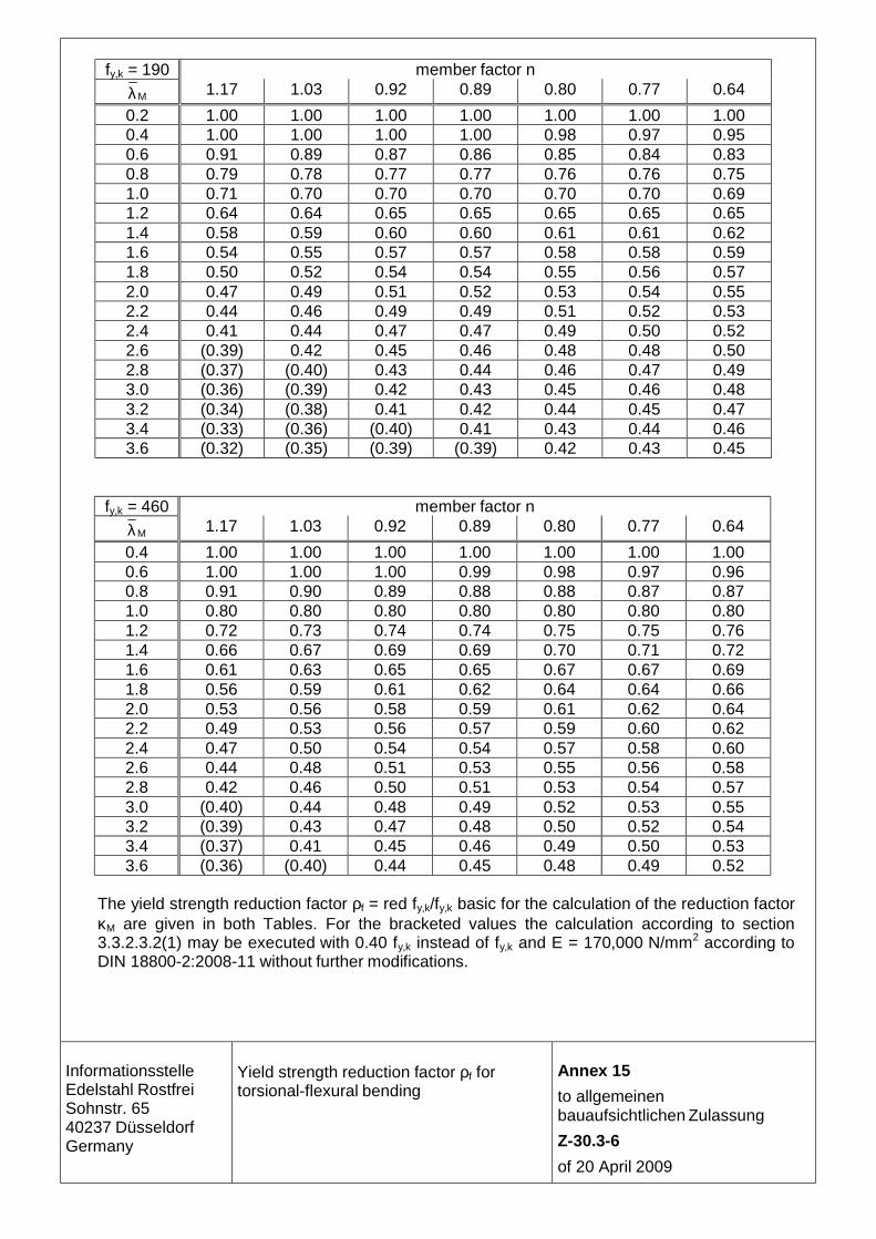
fy,k = 190 member factor n
Mλ 1.17 1.03 0.92 0.89 0.80 0.77 0.64
0.2 1.00 1.00 1.00 1.00 1.00 1.00 1.00 0.4 1.00 1.00 1.00 1.00 0.98 0.97 0.95 0.6 0.91 0.89 0.87 0.86 0.85 0.84 0.83 0.8 0.79 0.78 0.77 0.77 0.76 0.76 0.75 1.0 0.71 0.70 0.70 0.70 0.70 0.70 0.69 1.2 0.64 0.64 0.65 0.65 0.65 0.65 0.65 1.4 0.58 0.59 0.60 0.60 0.61 0.61 0.62 1.6 0.54 0.55 0.57 0.57 0.58 0.58 0.59 1.8 0.50 0.52 0.54 0.54 0.55 0.56 0.57 2.0 0.47 0.49 0.51 0.52 0.53 0.54 0.55 2.2 0.44 0.46 0.49 0.49 0.51 0.52 0.53 2.4 0.41 0.44 0.47 0.47 0.49 0.50 0.52 2.6 (0.39) 0.42 0.45 0.46 0.48 0.48 0.50 2.8 (0.37) (0.40) 0.43 0.44 0.46 0.47 0.49 3.0 (0.36) (0.39) 0.42 0.43 0.45 0.46 0.48 3.2 (0.34) (0.38) 0.41 0.42 0.44 0.45 0.47 3.4 (0.33) (0.36) (0.40) 0.41 0.43 0.44 0.46 3.6 (0.32) (0.35) (0.39) (0.39) 0.42 0.43 0.45
fy,k = 460 member factor n
Mλ 1.17 1.03 0.92 0.89 0.80 0.77 0.64
0.4 1.00 1.00 1.00 1.00 1.00 1.00 1.00 0.6 1.00 1.00 1.00 0.99 0.98 0.97 0.96 0.8 0.91 0.90 0.89 0.88 0.88 0.87 0.87 1.0 0.80 0.80 0.80 0.80 0.80 0.80 0.80 1.2 0.72 0.73 0.74 0.74 0.75 0.75 0.76 1.4 0.66 0.67 0.69 0.69 0.70 0.71 0.72 1.6 0.61 0.63 0.65 0.65 0.67 0.67 0.69 1.8 0.56 0.59 0.61 0.62 0.64 0.64 0.66 2.0 0.53 0.56 0.58 0.59 0.61 0.62 0.64 2.2 0.49 0.53 0.56 0.57 0.59 0.60 0.62 2.4 0.47 0.50 0.54 0.54 0.57 0.58 0.60 2.6 0.44 0.48 0.51 0.53 0.55 0.56 0.58 2.8 0.42 0.46 0.50 0.51 0.53 0.54 0.57 3.0 (0.40) 0.44 0.48 0.49 0.52 0.53 0.55 3.2 (0.39) 0.43 0.47 0.48 0.50 0.52 0.54 3.4 (0.37) 0.41 0.45 0.46 0.49 0.50 0.53 3.6 (0.36) (0.40) 0.44 0.45 0.48 0.49 0.52
The yield strength reduction factor ρf = red fy,k/fy,k basic for the calculation of the reduction factor κM are given in both Tables. For the bracketed values the calculation according to section 3.3.2.3.2(1) may be executed with 0.40 fy,k instead of fy,k and E = 170,000 N/mm2 according to DIN 18800-2:2008-11 without further modifications.
Informationsstelle Edelstahl Rostfrei Sohnstr. 65 40237 Düsseldorf Germany
Yield strength reduction factor ρf for torsional-flexural bending
Annex 15
to allgemeinen bauaufsichtlichen Zulassung
Z-30.3-6
of 20 April 2009

The delivery of the cross marked products requires to full fill the specific provisions to the verification of conformity of this national technical approval.
Company Strip Long products 1) Wire Sections 2 Hollow sections (pipes)
Fastening elements dowels
Name Postcode/Location Internet
Plate
cold rolled
hot rolled
rolled drawn (bright steel)
rolled drawn
Informationsstelle
Edelstahl R
ostfrei S
ohnstraße 65
40237 Düsseldorf
Germ
any
ArcelorMittal – Stainless Europe F-93212 La Plaine Saint-Denis www.arcelormittal.com/stainlesseurope X X X
Cogne Acciai Speciali SPA I-11100 Aosta www.cogne.com X X X
Deutsche Edelstahlwerke GmbH D-57078 Siegen www.dew-stahl.com X X X X
Hagener Feinstahl GmbH D-58089 Hagen www.hagener-feinstahl.de X X X
Hempel Special Metals GmbH D-46149 Oberhausen www.hempel-metals.com X X X X
Hoesch Schwerter Profile GmbH D-58239 Schwerte www.hoesch-profile.com X X X X
Mannstaedt GmbH D-53840 Troisdorf www.mannstaedt.de X X
Wilhelm Modersohn GmbH & Co. KG D-32139 Spenge www.modersohn.de X X X
Montanstahl AG CH-6855 Stabio www.montanstahl.com X X X
Manufacturer of products according
to Annex 1 T
able 1 (informative)
Aceros Inoxidables OLARRA S.A. E-48080 Bilbao www.olarra.com X X X X
Outokumpu GmbH D-47877 Willich www.outokumpu.com X X X X
Stalatube O FIN-15170 Lahti www.stalatube.com X
ThyssenKrupp Nirosta GmbH D-47807 Krefeld www.nirosta.de X X X
ThyssenKrupp VDM GmbH D-58751 Werdohl www.thyssenkruppvdm.de X X X X X X X
UGITECH GmbH D-71272 Renningen www.ugitech.com X X X X X
Wagener & Simon WASI GmbH & Co. KG
D-42289 Wuppertal www.wasi.de X
Walzwerke Einsal GmbH D-58769 Nachrodt www.walzwerke-einsal.de X X X X
Annex 16
to allgemeinen
bauaufsichtlichen Zulassung
Z-30.3-6
of 20 April 2009
1) forged long products as well
2) hot rolled as well as cut profiles, edged/bended profiles, laser beam welded profiles and hot extruded special profiles made of hot rolled

Informationsstelle Edelstahl RostfreiPostfach 10 220540013 Düsseldorf
www.edelstahl - rostfrei.de