solvent vs water based web coating
TRANSCRIPT
DESIGN CONSIDERATIONS IN
SOLVENT VS. WATER BASE
COATING EQUIPMENT
Robert A. PasqualePresident
New Era Converting MachineryP.O. Box 377
Hawthorne, NJ 07507
Overview
Many factors must be considered when designing, fabricating, installing and operating a coating line used to apply solvent based coatings.
We will cover many of these requirements and how they compare to water based coating systems. We will include discussions on:
•How the areas that require special design are established
•What special considerations are required to address these areas

What are solvent based and water based coatings?
Many of the coatings that are applied to webs substrates consist of particulate matter suspended in a liquid carrier. The distinction between these two types of coatings is based on whether the carrier is water or solvent(s).

Advantages of Solvent Based Coatings
Solvent based coatings offer several advantages over water based coatings including:
•They wet-out better, making them more applicable for consistent overall coatings
•Typically require less energy to remove allowing for lower drying temperatures, shorter dryers and/or faster speeds
•Solvent based adhesives typically have better performance characteristics such as higher shear/peel strength and greater moisture resistance

Disadvantages of Solvent Based Coatings
Though solvent based coatings offer several advantages over water based coatings, there are several disadvantages including:
•They contain harmful VOCs (Volatile Organic Compounds)
•They release flammable/explosive vapors/gases
•Safeguards required lead to more expensive coating equipment

Design Considerations
When designing a system for applying solvent based coatings the following major design requirements need to be addressed:
• The flammability/explosive issue
• The operators’ exposure to the solvents
• The release of VOCs to the environment
Design Considerations
We will briefly discuss the design of the drying equipment required for solvent versus water based coatings.
We will also address the design of the equipment to prevent excess corrosion when exposed to the coatings.

Equipment Design to Address Solvent Flammability
Of major concern is the potential of electrical components producing sparks in areas where solvent vapors/gases may be present. In the U.S. the NEC (National Electric Code) and in Canada the Canadian Electric Code (CEC) sets guidelines that:
•Define the areas where special electrical practices are required
•Define the electrical practices in those areas
Equipment Design to Address Solvent Flammability
The National Electrical Code (NEC) and the Canadian Electrical Code (CEC) defines hazardous areas as the following:
An area where a potential hazard (e.g., a fire, an explosion, etc.) may exist under normal or abnormal conditions because of the presence of flammable gases or vapors, combustible dusts or ignitable fibers or flyings.

Equipment Design to Address Solvent Flammability
Class DefinitionThe NFPA Publication 70, NEC, and CEC define three categories (Classes) of hazardous materials. The Classes define the type of explosive or ignitable substances which are present in the atmosphere such as:
– Class I locations are those in which flammable vapors and gases may be present.
– Class II locations are those in which combustible dust may be found.
– Class III locations are those which are hazardous because of the presence of easily ignitable fibers.

Equipment Design to Address Solvent Flammability
Division DefinitionEach of the three Classes is further subdivided into two Divisions. The Division defines the likelihood of the hazardous material being present in a flammable concentration.
– Division 1 - In which ignitable concentrations of hazards exists under normal operation conditions and/or where hazard is caused by frequent maintenance or repair work or frequent equipment failure
– Division 2 - In which ignitable concentrations of hazards are handled, processed or used, but which are normally in closed containers or closed systems from which they can only escape through accidental rupture or breakdown of such containers or systems.
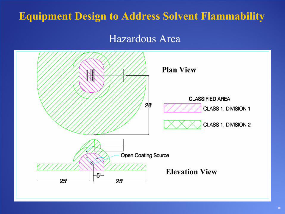
Equipment Design to Address Solvent Flammability
Hazardous Area
Plan View
Elevation View

Equipment Design to Address Solvent Flammability
Electrical Devices in the Hazardous Area
There are four classifications for the design/use of electrical components which are:
•Explosion Proof (XP) – designed and rated for use in a hazardous area
•Intrinsically Safe (IS) – designed so the electrical energy required by the device is below that requires to set off an explosion/ignition
•Air Purged – designed so that the electrical device is kept under positive pressure with non-solvent laden air
•Standard/General Purpose – no special design for preventing contact with/ignition of vapors or gases
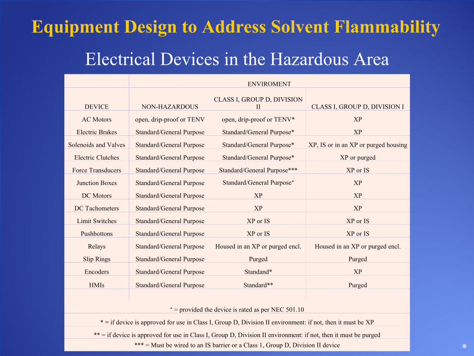
Equipment Design to Address Solvent Flammability
Electrical Devices in the Hazardous AreaENVIROMENT
DEVICE NON-HAZARDOUSCLASS I, GROUP D, DIVISION
II CLASS I, GROUP D, DIVISION I
AC Motors open, drip-proof or TENV open, drip-proof or TENV* XP
Electric Brakes Standard/General Purpose Standard/General Purpose* XP
Solenoids and Valves Standard/General Purpose Standard/General Purpose* XP, IS or in an XP or purged housing
Electric Clutches Standard/General Purpose Standard/General Purpose* XP or purged
Force Transducers Standard/General Purpose Standard/General Purpose*** XP or IS
Junction Boxes Standard/General Purpose Standard/General Purpose⁺ XP
DC Motors Standard/General Purpose XP XP
DC Tachometers Standard/General Purpose XP XP
Limit Switches Standard/General Purpose XP or IS XP or IS
Pushbottons Standard/General Purpose XP or IS XP or IS
Relays Standard/General Purpose Housed in an XP or purged encl. Housed in an XP or purged encl.
Slip Rings Standard/General Purpose Purged Purged
Encoders Standard/General Purpose Standand* XP
HMIs Standard/General Purpose Standard** Purged
⁺ = provided the device is rated as per NEC 501.10
* = if device is approved for use in Class I, Group D, Division II environment: if not, then it must be XP
** = if device is approved for use in Class I, Group D, Division II environment: if not, then it must be purged
*** = Must be wired to an IS barrier or a Class 1, Group D, Division II device
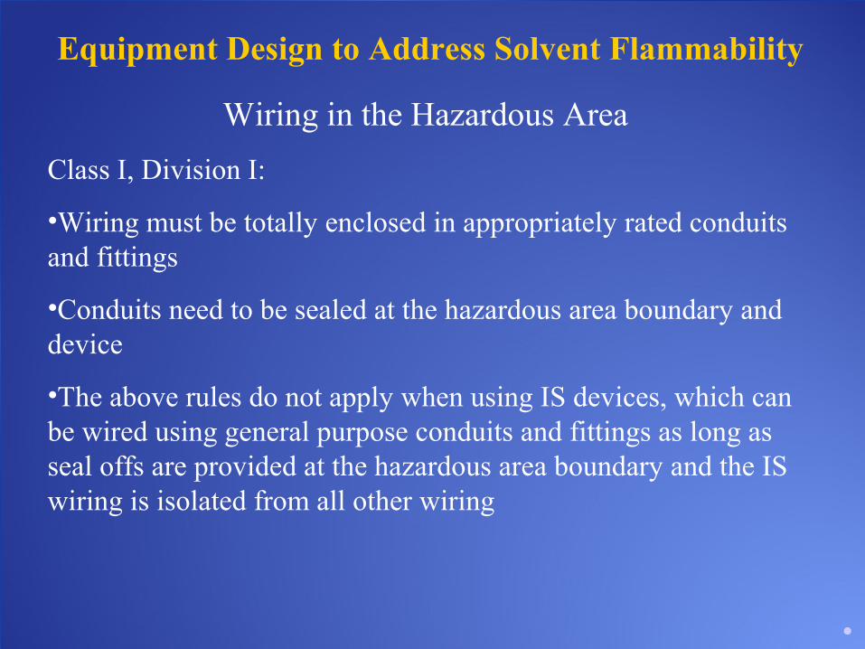
Equipment Design to Address Solvent Flammability
Wiring in the Hazardous Area
Class I, Division I:
•Wiring must be totally enclosed in appropriately rated conduits and fittings
•Conduits need to be sealed at the hazardous area boundary and device
•The above rules do not apply when using IS devices, which can be wired using general purpose conduits and fittings as long as seal offs are provided at the hazardous area boundary and the IS wiring is isolated from all other wiring

Equipment Design to Address Solvent Flammability
Wiring in the Hazardous Area
Class I, Division II:
•General purpose conduit and fittings can be used as long as seal offs are used at each potential spark generating device

Equipment Design to Address Solvent Flammability
Coater Wired for Non-Hazardous Area Coater Wired for Class I, Group D, Division I

Equipment Design to Address Solvent Flammability
General Comments
•Devices that are rated for use in an XP area are more costly than those that are rated General Purpose
•The material and labor costs associated with wiring in an XP area are higher than a General Purpose area
•In addition to the electrical components, one needs to address static electricity as a potential source of ignition
Equipment Design to Address Solvent Flammability
General Comments
•It is important that all personnel and hardware in the area is properly grounded
•Portable electronic devices should be restricted in the hazardous area.
•The use of typical water based coatings eliminated the need for the use of special devices and wiring.

Design of the Equipment for Operator Health
Exposure to solvent has short and long term health effects such as:
•Irritation of the skin, eyes, nose, and throat
•Headaches
•Nausea
•Damage to the liver, kidney, lungs and central nervous system
Because of this the equipment should be designed to minimize the operators’ exposure to the solvents
Design of the Equipment for Operator Health
Methods to Limit Operators’ ExposurePersonal Protection Equipment
The use of personal protection equipment (glasses, gloves, respirators, etc.) is the most basic form of limiting operators’ exposure. However, the use of this equipment can reduce the operators’ ability to perform the required tasks associated with the operation of the coating equipment.
Design of the Equipment for Operator Health
Methods to Limit Operators’ ExposureVentilation Equipment
The use of ventilation equipment local to the coater is often used to reduce the operators’ exposure. However, this too has its disadvantages.
•Placing exhaust hoods over the coater has several issues:
– Since solvent vapors are typically heavier than air an overhead hood is typically ineffective at capturing them.
– If the hood is strong enough to capture some of the solvent vapors, it often drags the vapors past the operators’ face.
•Providing ventilation at the bottom of the coater is more effective at capturing the heavier than air solvent vapors but may not reduce the operators’ exposure enough.

Design of the Equipment for Operator Health
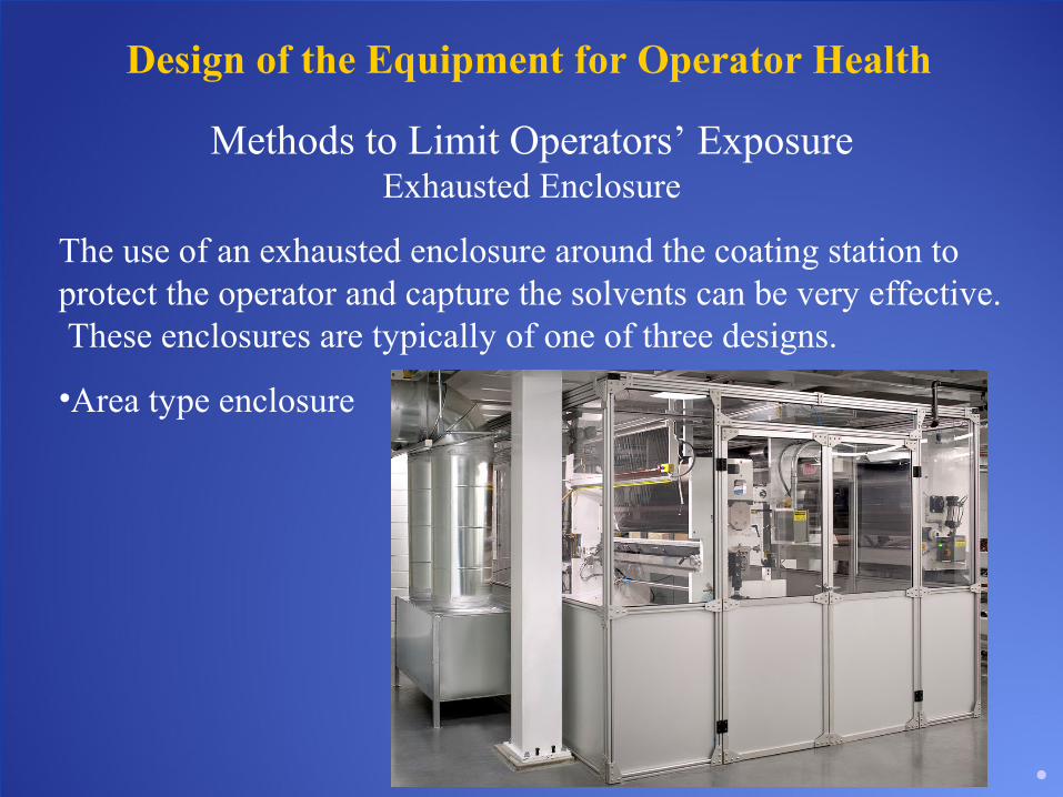
Methods to Limit Operators’ ExposureExhausted Enclosure
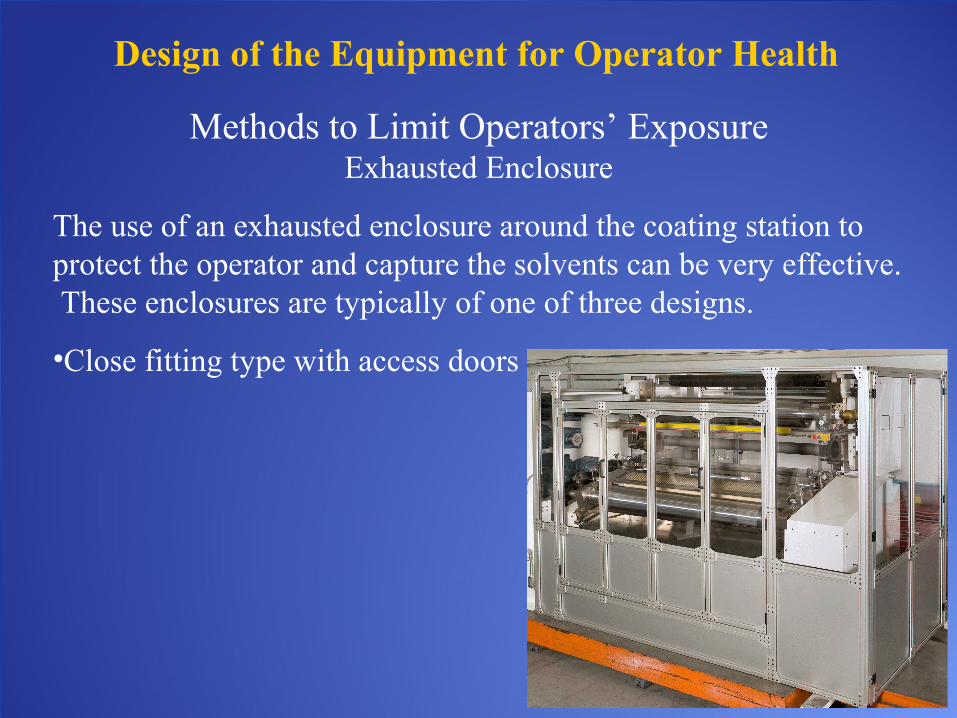
The use of an exhausted enclosure around the coating station to protect the operator and capture the solvents can be very effective. These enclosures are typically of one of three designs.
•Area type enclosure
– Surrounds both the coater and the operator area around it.
– These enclosures require the operator to enter them in order to make adjustments to the coater, therefore still requiring the use of personal protection equipment when doing such.
Design of the Equipment for Operator Health
Methods to Limit Operators’ ExposureExhausted Enclosure
The use of an exhausted enclosure around the coating station to protect the operator and capture the solvents can be very effective. These enclosures are typically of one of three designs.
•Area type enclosure
Design of the Equipment for Operator Health
Methods to Limit Operators’ ExposureExhausted Enclosure
The use of an exhausted enclosure around the coating station to protect the operator and capture the solvents can be very effective. These enclosures are typically of one of three designs.
•Close fitting type with access doors
– Designed to fit tightly around the coater but requires the operator to open doors/hatches to make adjustments.
– Design limits the operators’ exposure during operation but it doesn’t eliminate it (during adjustments).
– Exposure can be reduced by using a multi-speed exhaust fan that increases in capacity when the access doors/hatches are open.
Design of the Equipment for Operator Health
Methods to Limit Operators’ ExposureExhausted Enclosure
The use of an exhausted enclosure around the coating station to protect the operator and capture the solvents can be very effective. These enclosures are typically of one of three designs.
•Close fitting type with access doors

Design of the Equipment for Operator Health
Methods to Limit Operators’ ExposureExhausted Enclosure
The use of an exhausted enclosure around the coating station to protect the operator and capture the solvents can be very effective. These enclosures are typically of one of three designs.
•Close fitting type with external adjustments
– Controls required for adjusting located outside the enclosure.
– Operator exposure to the vapors/gases is all but eliminated during operation.
– Only time that access is required inside the enclosure is during maintenance.

Design of the Equipment for Operator Health
Methods to Limit Operators’ ExposureExhausted Enclosure
The use of an exhausted enclosure around the coating station to protect the operator and capture the solvents can be very effective. These enclosures are typically of one of three designs.
•Close fitting type with external adjustments

Design of the Equipment for Operator Health
Methods to Limit Operators’ ExposureExhausted Enclosure
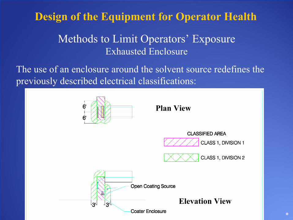
The use of an enclosure around the solvent source redefines the previously described electrical classifications:
•The Class I, Group D, Division I area is limited to inside the enclosure
•The Class I, Group D, Division II area is significantly smaller and is related to the location of the enclosure openings.
Design of the Equipment for Operator Health
Methods to Limit Operators’ ExposureExhausted Enclosure
The use of an enclosure around the solvent source redefines the previously described electrical classifications:
Plan View
Elevation View
Design of the Equipment for Operator Health
General Comments
•Certain features need to be included in the design of a coater enclosure including:
– The use of safety glass
– Adequate explosion relief panels/surfaces
– The use of solvent level monitoring equipment (LFL monitors)
•When using water based coatings:
– The need for personal protection equipment is greatly reduced
– The need for ventilation equipment and/or coater enclosures is also greatly reduced

Design of Equipment for Emissions
The design of the coating system for the capture and abatement of the solvent vapors/gases is extremely important in order to prevent them from being released to the atmosphere.
The use of the previously discussed ventilation equipment and/or coater enclosure allows for the capture of these vapors/gases in the exhaust air stream. Once captured, there are several ways to deal with these vapors/gases, including:
•Recovery - the solvent vapors/gases are separated from the air stream so that they can be collected either for destruction or reuse
•Destruction - allows for the destruction of the vapors/gases present in the air stream (incineration)

Design of Equipment for Emissions
General Comments
•The air stream that exits these sections is typically combined with the air stream(s) from the drying equipment and fed to a common collection or destruction unit.
•Because the air stream from the coater exhaust system is often low in solvent content, it is common to use this air to feed the drying recirculating system, allowing for the solvent content to raise, helping to minimize the size of the abatement equipment.
•With typical water base coatings, since there are no harmful vapors/gases being release, there is no need for abatement equipment.
Drying Equipment for Solvent Based and Water Based Coatings
Design differences of solvent versus water based drying systems is a very large topic of discussion which deserves its own paper. However, there are several major differences that we can briefly touch on:
•Solvents typically take much less energy to remove, allowing for lower drying temperatures, shorter dryers and/or faster speeds.
•Solvent based dryer required the inclusion of explosion relief panels.
•Prior to operation, solvent based dryers need to go through a purge cycle to make sure that no residual solvents are present.

Drying Equipment for Solvent Based and Water Based Coatings
Design differences of solvent versus water based drying systems is a very large topic of discussion which deserves its own paper. However, there are several major differences that we can briefly touch on:
•The solvent dryer’s air handling equipment needs to be designed to assure that the levels of solvent in the air never go above a certain percentage and may require LFL monitors.
•The air stream exhausted from the solvent dryer needs to be fed to an abatement system.
•The internals of a dryer for water based coatings needs to be designed to prevent corrosion, with stainless steel often being used.

Equipment Design for Corrosion Resistance
Equipment used with solvent or water based coatings needs to be designed to address the detrimental effects of exposure to these coatings. Examples of this are:
•For solvent based coatings – Certain solvents attack mild steel. Therefore special coatings or materials of construction may need to be employed.
•For water based coatings - The concern of corrosion due to oxidation should be addressed either through coatings such as chrome, etc. applied to the mild steel, through the use of special materials of construction such as stainless steel or by cladding exposed surfaces with stainless steel.
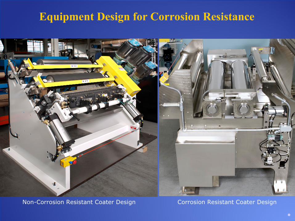
Equipment Design for Corrosion Resistance
Non-Corrosion Resistant Coater Design Corrosion Resistant Coater Design

Conclusions
There are many factors that need to be considered when designing a system to handle solvent based coatings. Care must be taken to assure that fires/explosions will not occur, that the operators will not be exposed to the solvent vapors/gases and that the vapors/gases are properly captured so that they are not released into the environment. In addition the coater should be designed to prevent excessive corrosion that may occur from contact with the coating.
Acknowledgment
We acknowledge the following references:
www.exmanlift.com
National Fire Protection Association’s National Electric Code handbook 13th edition
Canadian Standards Association’s Canadian Electrical Code 22nd edition