solvent extraction liquid-liquid extraction prepared by dr.nagwa el- mansy cairo university chemical...
TRANSCRIPT
Solvent ExtractionLiquid-Liquid Extraction
Prepared by Dr.Nagwa El- mansyCairo University
Chemical Engineering Department
Liquid-Liquid Extraction
“The separation of the components of a liquid mixture by treatment with a solvent in which one or more of the desired components is preferentially soluble is known as liquid–liquid extraction.”
In this operation, it is essential that the liquid-mixture feed and solvent are at least partially miscible ( some time completely immiscible).
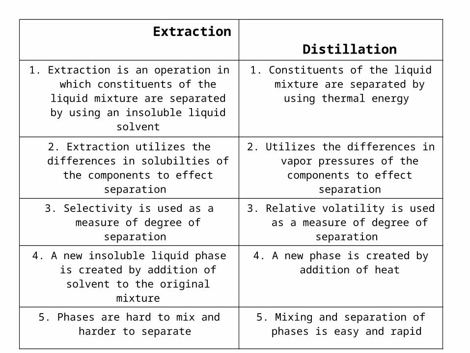
Extraction Distillation
1. Extraction is an operation in which constituents of the liquid mixture are separated by using
an insoluble liquid solvent
1. Constituents of the liquid mixture are separated by using thermal energy
2. Extraction utilizes the differences in solubilties of the components to effect separation
2. Utilizes the differences in vapor pressures of the components to effect separation
3. Selectivity is used as a measure of degree of separation
3. Relative volatility is used as a measure of degree of separation
4. A new insoluble liquid phase is created by addition of solvent to the original mixture
4. A new phase is created by addition of heat
5. Phases are hard to mix and harder to separate 5. Mixing and separation of phases is easy and rapid
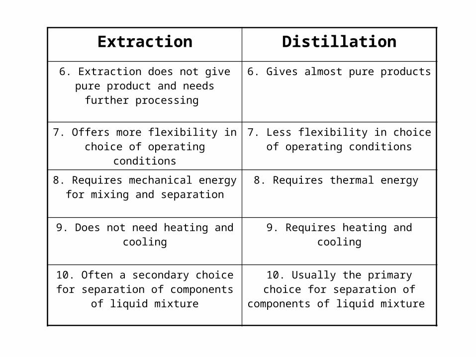
Extraction Distillation
6. Extraction does not give pure product and needs further processing
6. Gives almost pure products
7. Offers more flexibility in choice of operating conditions
7. Less flexibility in choice of operating conditions
8. Requires mechanical energy for mixing and separation
8. Requires thermal energy
9. Does not need heating and cooling 9. Requires heating and cooling
10. Often a secondary choice for separation of components of liquid mixture
10. Usually the primary choice for separation of components of liquid mixture
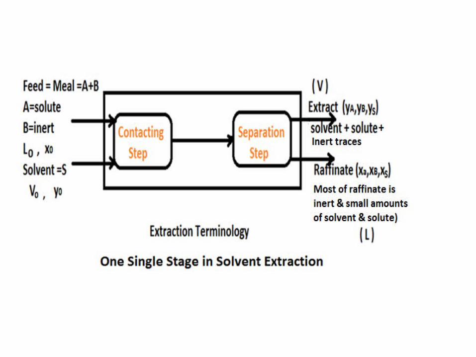
The mechanism of extraction involves two steps whichare:-
First Step:-Contacting Step:- Bringing the feed mixture and the solvent into intimatcontact.
Second Step:-Separation Step:- Separation of the resulting two phases. It is done by:- distillation, evaporation, Crystallization.

It is possible to combine first two stages into a single
piece of equipment such as a column which is then
operated continuously. Such an operation is known
as differential contacting.
Liquid–liquid extraction is also carried out in stage-
wise equipment, the prime example being a mixer–
settler unit in which the main features are the
mixing of the two liquid phases by agitation,
followed by settling in a separate vessel by gravity.
Applications of liquid-liquid extraction in petroleum Field:-1- Removal of aromatics from Kerosene (EdeleanuProcess) , It is one of the most important processes forrefining Kerosene which improves the smoke point ofKerosene and Jet fuels by removing the aromaticscontent by Liquid sulphur dioxide.(Smoke point is thetemperature at which it gives off smoke).2-Removal of asphaltenes from lube oil which cause friction by using propane as a solvent.3-Dewaxing of lube oil by using propane as a solvent.4-Improving kinematic viscosity index (KVI) of lube oil

By removing aromatics and naphthens using phenol or furfural. [KVI measures the variation of viscosity withtemperature. Paraffin has high (KVI) so presence ofaromatics decreases(KVI)].( KV = µ/ρ = --- cm2/sec = stock )Separation Factor (Selectivity) :- β
A B
A B
A
A
B
B
y y β =
x x
y = mole fraction of A in extract.
x = mole fraction of A in raffinate.
y = mole fraction of B in extract.
x = mole fraction of B in raffinate.

β = It is a measure of effectiveness of separation.The solvent is said to be effective or selective when βexceeds unity.
The higher the selectivity the higher the separation.
A B A A
A B B B
y y y x β = > 1 (solvent is selective)
x x y x
β = 1 (no separation)

Choice of solvent:-1- High selectivity ( high β → high yA/xA and low yB/xB)
2-Easy to be recovered.3-Density:- The higher the density difference betweenExtract and raffinate the easier the segregation of bothPhases.4-Surface tension:- The larger the surface tension the higher the power needed to mix the two liquids withthe solvent but the easier the segregation.5- Other criteria:- non-corrosive , chemically stable ,non-toxic , low viscosity , low vapor pressure.
Equilibrium Relations:-In liquid-liquid extraction we have three componentsystem:-1- solute (A)→liquid.2- Inert (B)→liquid.3- Solvent (S)→liquid.Representing the three component system on rightangle triangle as follows :-
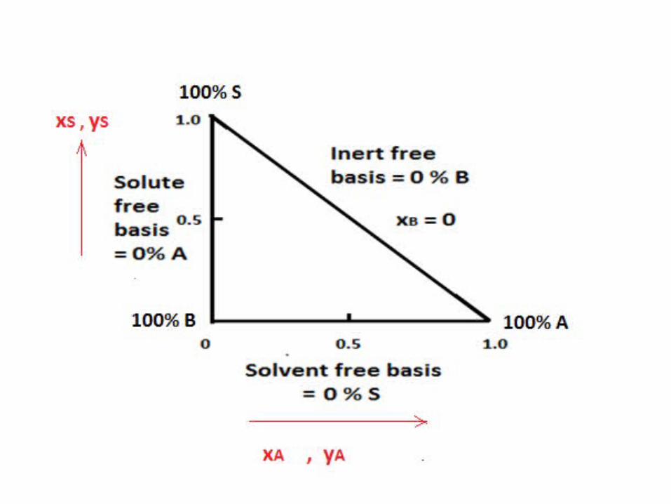

Types of phase diagram = Solubility diagram = Ternarydiagram.Two main diagram :-A- Closed Ternary System:-
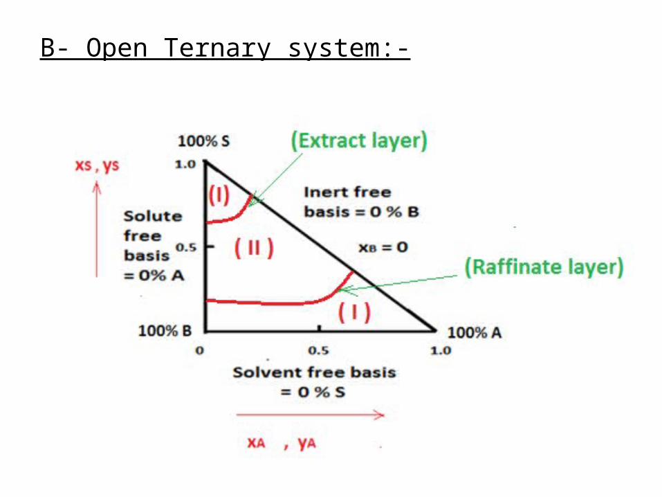
B- Open Ternary system:-
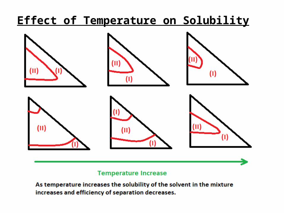
Effect of Temperature on Solubility Diagram:-


Addition of two streams:-
AP AQ AR
BP BQ BR
SP SQ SR
P + Q = R
P x + Q x = R x
P x + Q x = R x
P x + Q x = R x
By using lever arm principle,
the length and amounts
are calculated as follows:-
PR Q a = =
RQ P b

Subtraction of two streams:-
AN AM AK
BN BM BK
SN SM SK
N - M = K
N x - M x = K x
N x - M x = K x
N x - M x = K x
By using lever arm principle,
the length and amounts
are calculated as follows:-
NK M b' = =
MK N a' + b'
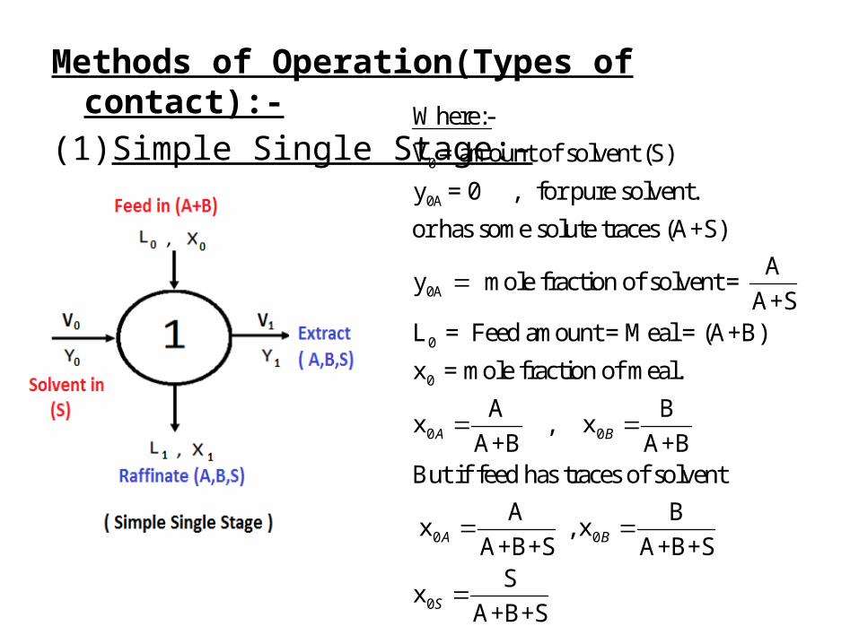
Methods of Operation(Types of contact):-(1) Simple Single Stage:-
0
0A
0A
0
0
0
Where:-
V = amount of solvent (S)
y = 0 , for pure solvent.
or has some solute traces (A+S)
Ay mole fraction of solvent =
A+SL = Feed amount = Meal = (A+B)
x = mole fraction of meal.
Ax
A+BA
0
0 0
0
B , x
A+BBut if feed has traces of solvent
A B x , x
A+B+S A+B+SS
xA+B+S
B
A B
S
0 0 1 1
0 0 0 0 1 1 1 1 M
0 0 M
1 1 M
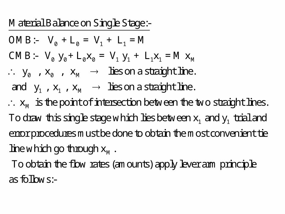
Material Balance on Single Stage:-
OMB:- V + L = V + L = M
CMB:- V y + L x = V y + L x = M x
y , x , x lies on a straight line.
and y , x , x lies on a straigh
M
1 1
t line.
x is the point of intersection between the two straight lines.
To draw this single stage which lies between x and y trial and
error procedures must be done to obtain the most convenient tie
Mline which go through x .
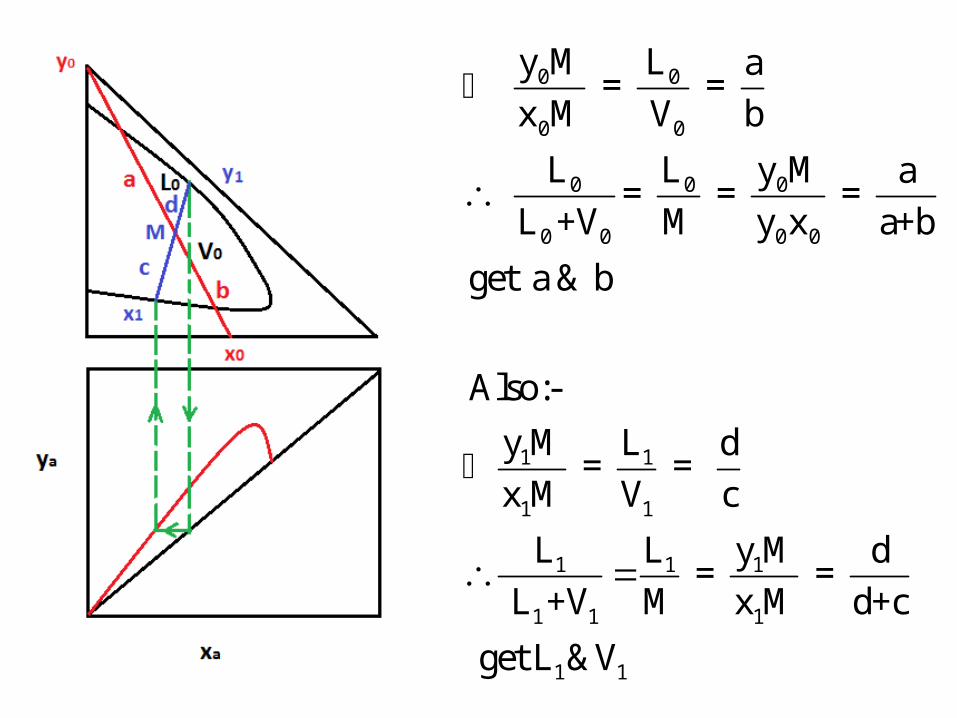
To obtain the flow rates (amounts) apply lever arm principle
as follows:-
0 0
0 0
0 0 0
0 0 0 0
1 1
1 1
1 1 1
1 1 1
1 1
y M L a = =
x M V b
L L y M a = = =
L +V M y x a+b
get a & b
Also:-
y M L d = =
x M V c
L L y M d = =
L +V M x M d+c
get L &V
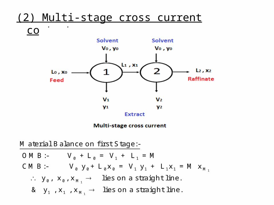
(2) Multi-stage cross current contact:-
1
1
1
0 0 1 1
0 0 0 0 1 1 1 1 M
0 0 M
1 1 M
Material Balance on first Stage:-
OMB:- V + L = V + L = M
CMB:- V y + L x = V y + L x = M x
y , x , x lies on a straight line.
& y , x , x lies on a s
traight line.

1M
1 1
x is the point of intersection between the two straight lines.
To draw this single stage which lies between x and y trial
and error procedures must be done to obtain the most convenient
tieline wh
1M
1 1
ich go through x .To obtain the flow rates
(amounts V , L ) apply lever arm principle
2
2
2
0 1 2 2
0 0 1 1 2 2 2 2 M
0 1 M
1 1 M
Material Balance on second Stage:-
OMB:- V + L = V + L = M
CMB:- V y + L x = V y + L x = M x
y , x , x lies on a straight line.
& y , x , x lies on a
2M
2 2
straight line.
x is the point of intersection between the two straight lines.To draw this
single stage which lies between x and y trial and error procedures must be
done to obtain the most conven
M2
2 2
ient tieline which go through x .
To obtain the flow rates (amounts V , L ) apply lever arm principle

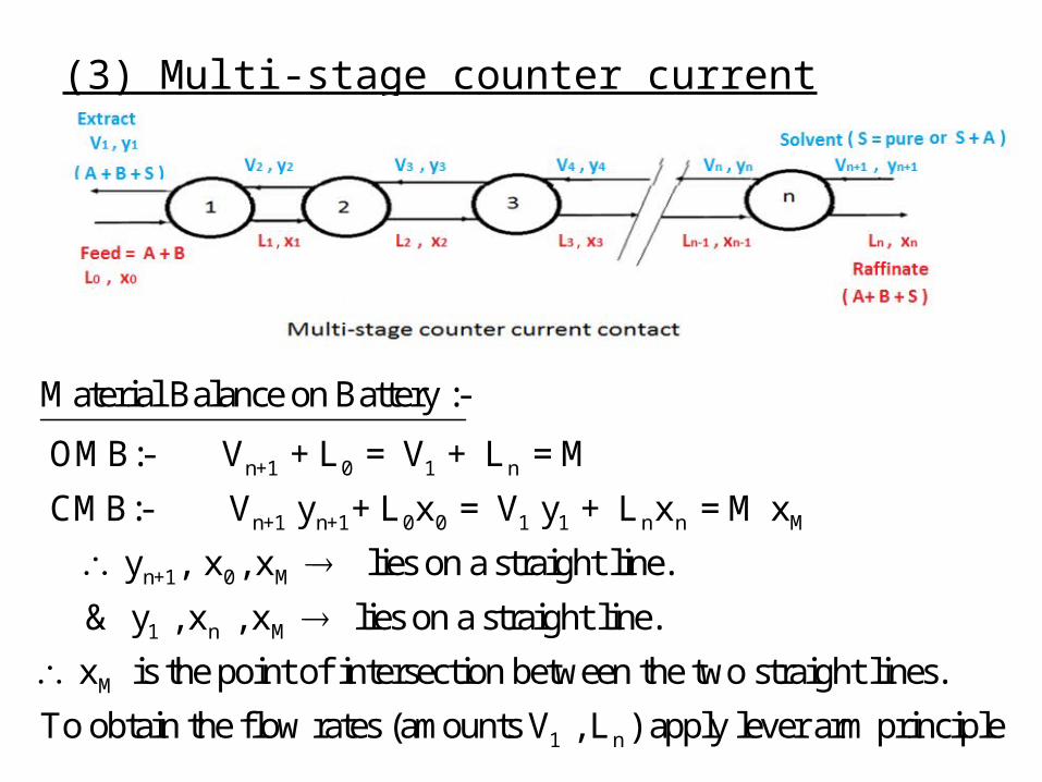
(3) Multi-stage counter current contact:-
n+1 0 1 n
n+1 n+1 0 0 1 1 n n M
n+1 0 M
1 n M
Material Balance on Battery :-
OMB:- V + L = V + L = M
CMB:- V y + L x = V y + L x = M x
y , x , x lies on a straight line.
& y , x , x lies on a
M
1 n
straight line.
x is the point of intersection between the two straight lines.
To obtain the flow rates (amounts V , L ) apply lever arm principle
n+1 0 1 n
n+1 n 1 0
n+1 n+1 n n 1 1 0 0
n+1 n
1 0
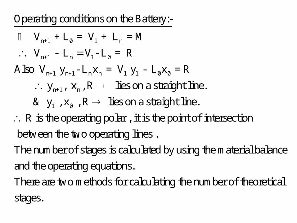
Operating conditions on the Battery:-
V + L = V + L = M
V - L V - L = R
Also V y - L x = V y - L x = R
y , x , R lies on a straight line.
& y , x
, R lies on a straight line.
R is the operating polar , it is the point of intersection
between the two operating lines .
The number of stages is calculated by using the material balance
and the oper
ating equations.
There are two methods for calculating the number of theoretical
stages.


Continuous contact(packed or spray columns) inliquid-liquid extraction:-In continuous contact using packed column, one of the phases is dispersed into the other phase and allowed toflow counter currently past the other phase(either up-wards or down-wards). Separation of the phases is notaccomplished until the outlets are reached. Since contacting and separation do not take place at a number of discrete stages, equilibrium conditions are never reached with this type of equipment.The effectiveness of a continuous contact tower, maybe expressed as:-
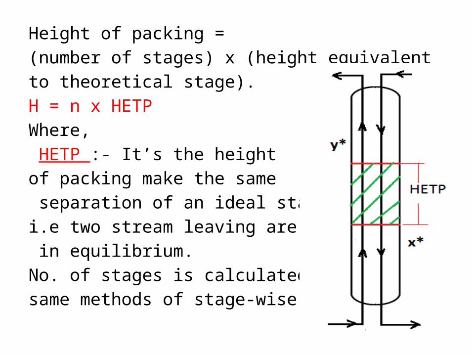
Height of packing =(number of stages) x (height equivalentto theoretical stage).H = n x HETPWhere, HETP :- It’s the height of packing make the same separation of an ideal stagei.e two stream leaving are in equilibrium.No. of stages is calculated by thesame methods of stage-wise contact
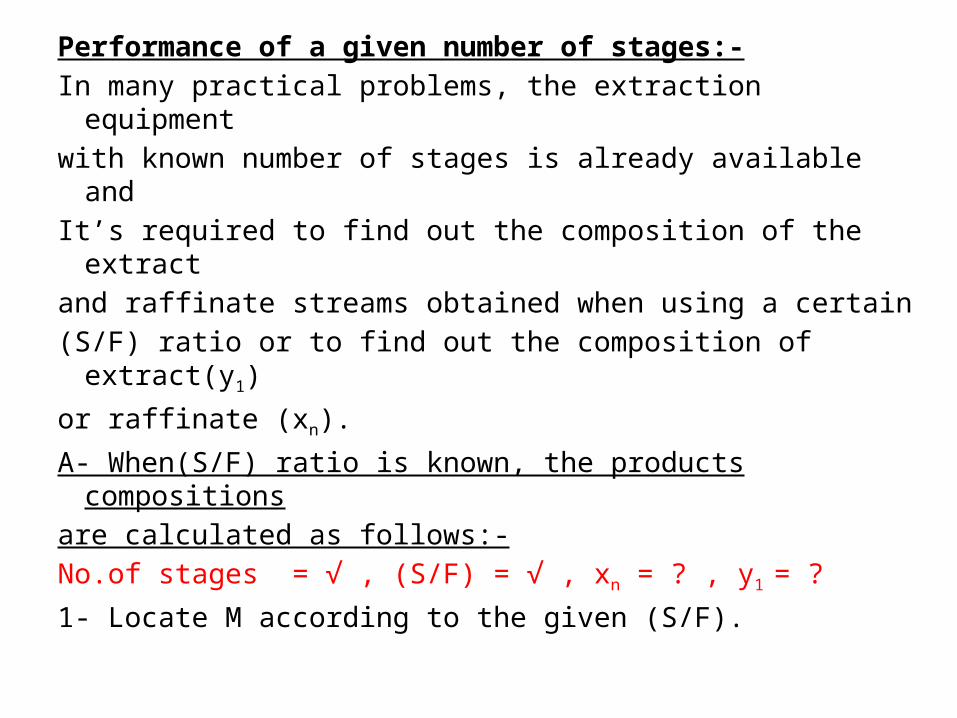
Performance of a given number of stages:-In many practical problems, the extraction equipmentwith known number of stages is already available andIt’s required to find out the composition of the extractand raffinate streams obtained when using a certain(S/F) ratio or to find out the composition of extract(y1)
or raffinate (xn).
A- When(S/F) ratio is known, the products compositionsare calculated as follows:-No.of stages = √ , (S/F) = √ , xn = ? , y1 = ?
1- Locate M according to the given (S/F).

2- Assume xn on raffinate locus.
3-Extend xnM to obtain y1 on the extract locus.
4- Obtain R at the intersection of x0y1 , xnyn+1 and
proceed to obtain number of theoretical stages.5- If the no. of stages founds corresponds to thespecified no., the assumption of xn is correct and
correspond to this composition (xn).
If → n calculated > or < n given , a new xn is assumed.
6-The same procedure is repeated until the assumed xn
yield the specified no. of stages.7- y1 is obtained by connecting xnM and extend to cut
extract locus at y1.


B-When the composition of the product raffinatestream is known, the problem will be to calculate theamount of solvent and the corresponding extractcomposition.Given:- xn = √ , no. of stages = n = √ , (S/F) = ? , y1 = ? ,
yn+1= √.• The trials procedure goes along the same line of material balance (position of point M).• The number of stages obtained is plotted against (S/F)• The required amount of solvent for the given no. ofstage is obtained from the curve.

• The correct M point is obtained .• Connect xn with M then extend to cut the extract
locus at y1.

Minimum solvent requirements:-As the (S/F) ratio decreases:-1- Number of stages increases.2-y1 increases to y1’ and y1” .
3- M moves from M’ and M”.4- R moves from R’ and R’’ i.e slopes of M.B lines rangefrom -ve to ∞ to +ve.5- For ∞ no. of stages , same minimum solventrequirements and maximum extract conditions.
(S/F) min → ∞ no. of stages →y1 max
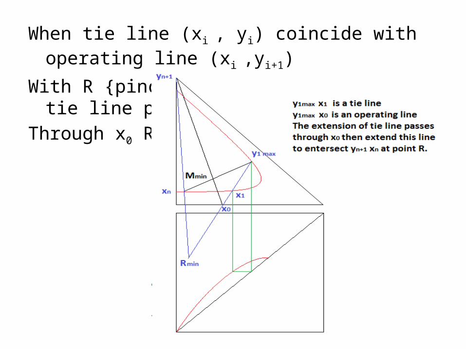
When tie line (xi , yi) coincide with operating line (xi ,yi+1)
With R {pinch occur when extension of tie line passesThrough x0 R}.

The conditions of minimum solvent requirements maybe plotted on x-y diagram, the coincidence of a tie lineand a material balance line on polar plot ,meaning thatyi = yi+1 →the operating line and equilibrium curvehaving a common point.As S/F is reduced the operating curve moves fromposition(1) to (2) and(3) getting nearer to the equilibriumcurve until it cuts it or touches it (position(3)) whichcorresponds to minimum solvent requirements andmaximum extract composition(y1max) as shown in the
following Figure.


Optimum (S/F) ratio:-When designing a new extraction battery the number ofstages and (S/F) ratio are unknown. The optimumconditions of no. of stages and (S/F) ratio is determinedas (S/F) increases, no. of stages decreases , but capacityof equipment tohandle the increasing amount of solventincreases. As (S/F)increases the solutionbecome more dilutewhich increase the costof solvent removal unit.
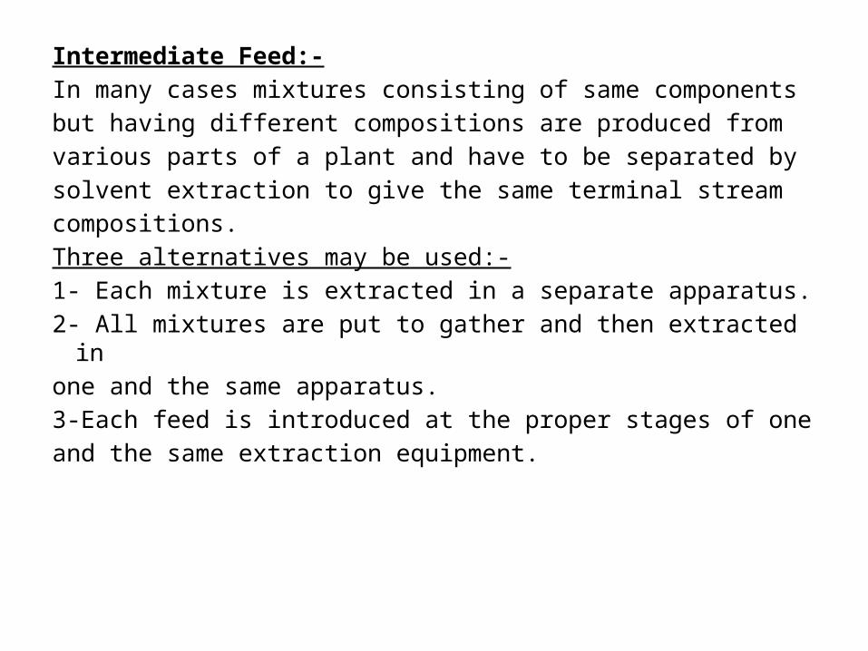
Intermediate Feed:-In many cases mixtures consisting of same componentsbut having different compositions are produced fromvarious parts of a plant and have to be separated bysolvent extraction to give the same terminal streamcompositions.Three alternatives may be used:-1- Each mixture is extracted in a separate apparatus.2- All mixtures are put to gather and then extracted in one and the same apparatus.3-Each feed is introduced at the proper stages of oneand the same extraction equipment.

The last solution is the most economic and correspondsto lower number of stages.The feed stream richer in solute is introduced atstage(1) while the other feed which contains lessamount of solute is introduced at later stages so thatthe composition of each feed is closest to the composition of the raffinate stream to which it isadded.

0 F n+1 1 n
0 F T 0 F T
T n+1 1 n
T T n+1 n+1 1 1 n n M
n+1
OMB on the Battery:-
1- L + L + V = V + L = M
L + L = L x , x , x lies on a str. line.
L + V = V + L = M
L x + V y = V y + L x = M x
VTo get the amounts:-
L
n+1 T M
0 F T n+1 M
V x x = =
+ L L y x

n+1 n F 1 0
F
n+1 n 1 0 F
n+1 n
n+1 n
1
2- Consider R is the overall operating polar:-
V - L + L = V - L
R + L = R' R , x ,R'
Also V - L = V - (L L )
R = V - L
R , y , x
R = V - ( L
F
0 F
1 T 1 T
f+1 f F
f+1 f+1
+ L )
R = V - L R , y , x
R = V - ( L + L )
R = V - L R , y , x
1 0 1 0
f+1 f f+1 f
F f
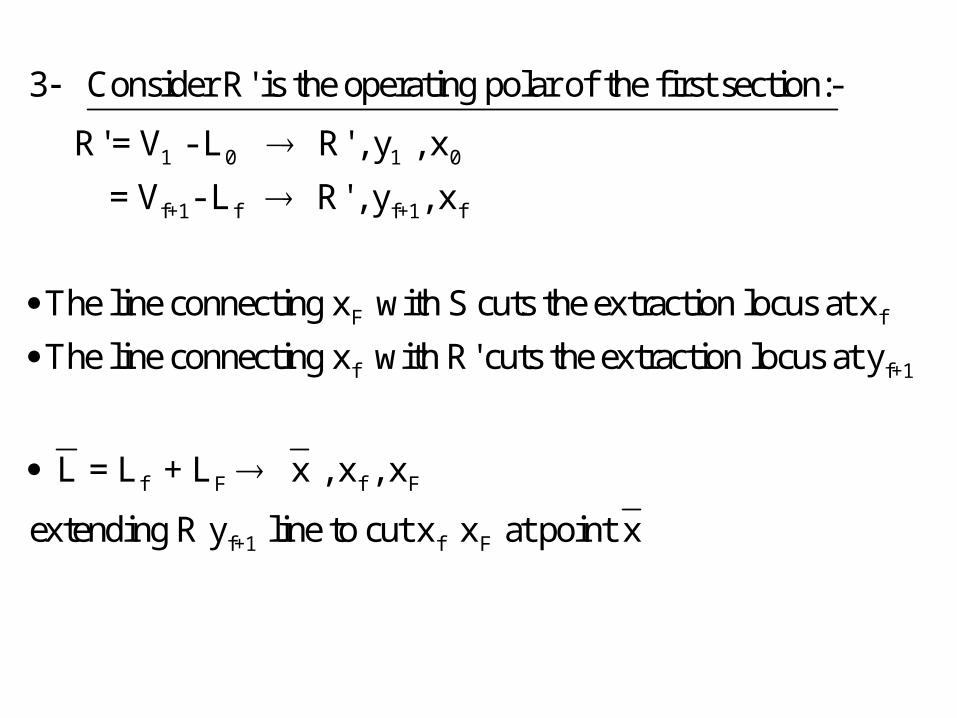
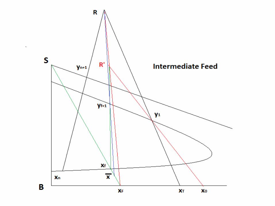
3 Consider R' is the operating polar of the first section:-
R' = V - L R' , y , x
= V - L R' , y , x
The line connecting x with S cuts the extraction locus at x
The line
f f+1
f F f F
f+1 f F
connecting x with R' cuts the extraction locus at y
L = L + L x , x , x
extending R y line to cut x x at point x

Extract with reflux:-The maximum composition of extract product fromCountercurrent multi-stage(y1max) occurs when the
(S/F)min is used.
This maximum composition at best situation at the endof the tie line passing through feed point, and even inthat case an ∞ no. of stages is required .In practice it is always desirable to have an extract asrich as possible in the solute, richer than the compositionof a layer in-equilibrium with the liquid feed.This could be possible by using “Enriching with reflux” or“Extract reflux” .

Which means:- y 1 with reflux > y 1 max
Although extract reflux enrich the extract product itrequires using large amount of Solvent/unit quantity ofFeed.
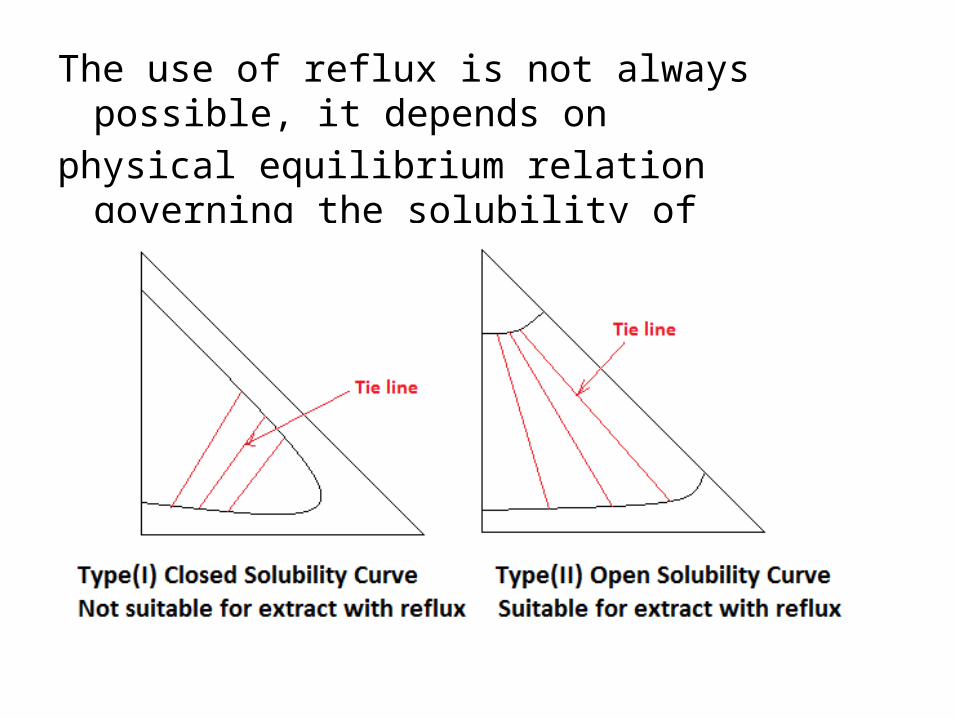
The use of reflux is not always possible, it depends onphysical equilibrium relation governing the solubility ofThe system at hand(limitation).

For systems having a phase diagram of type(I), the length oftie lines get shorter as the composition of the extract phasesget richer in solute. Which means that the effluentcompositions are closer to one another, which makes theseparation of the two phases difficult. This limitation is notpresent in type(II).
Graphical Representation of extract with reflux:-Assumption concerning the behavior of the solvent removalunit:-1- Nothing of the raffinate component (B) entering unit,Leaves with the separated solvent stream V, all (B) goes toL0 and D. Accordingly (V) is a mixture of (S+A) and its
composition (y) on the hypotenuse.

2-(L0 + D ) stream from (SRU) is saturated with solvent
and lies on raffinate stream (x0 = xD lies on raffinate).
3- The feed stream ( xf ) lies on raffinate locus.
(note:- These simplifications are not essential and theextract problem can be solved without them).The ratio of reflux L0 to final extract product D is termed
the reflux ratio. The higher the ratio the higher theenrichment of the extract with a given number of stages.• If a feed stream LF with composition xF is to be
separated into extract with composition(xD = x0) and
raffinate composition xn , using extract reflux as shown in
the previous Figure. The rich solvent stream leaving thetop of (SRU) has composition(y).
n f D 0 n+1
1 0
1 0
01
0
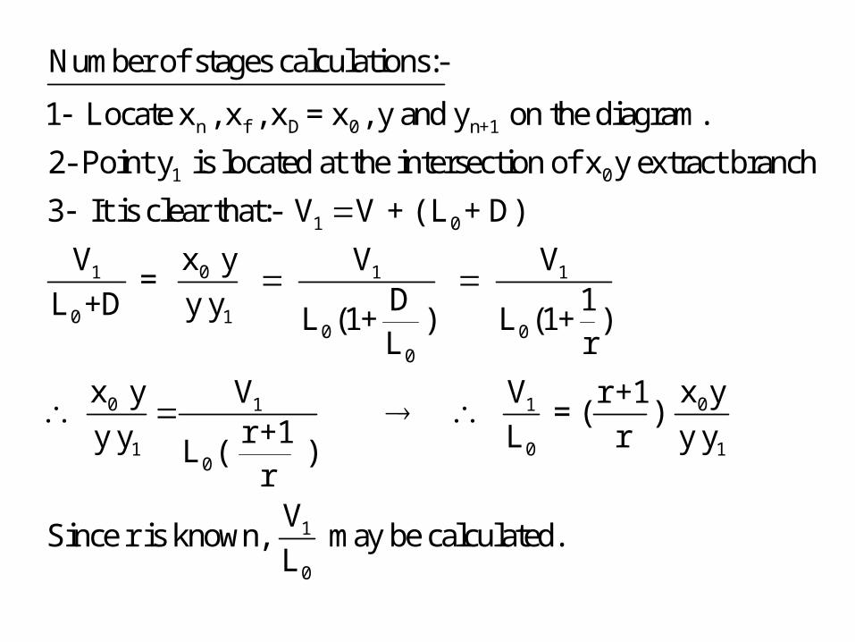
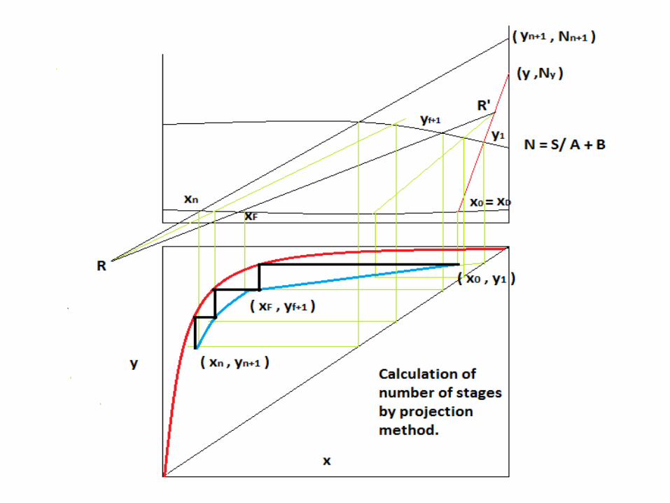
Number of stages calculations:-
1 Locate x , x , x = x , y and y on the diagram.
2- Point y is located at the intersection of x y extract branch
3 It is clear that:- V V + ( L + D)
x yV =
L +D y
1 1
10 0
0
0 01 1
1 0 10
1
0
V V
D 1y L (1+ ) L (1+ )L r
x y x yV V r +1 = ( )
r +1y y L r y yL ( )r
VSince r is known, may be calculated.
L

1 0 f+1 f
0 10 1
1 0
1
f f F
f
4 R' = V - L = V - L
x R' V R' lies on the extention of x y so that =
R' y L
Also R' lies between y and y .
5- x is located on the raffinate (notice that x coinside with x ).
Connecting x t
f+1
n+1 n f+1 f F F
F F n n+1
o R' it cuts the extract locus at y which is also
the extract composition leaving the second section.
6- R = V - L = V - ( L + L ) = R' - L
Connecting x to R', x R' intersects x y at R.
7- The number of stages in each section may be calculated by usual
polar construction using points R' and R respectively.
8- The operating curve may be projected on x-y diagram and
the number of stages can be obtained.

0 01
0 1 1
1
1 0
1 0
x R' x yV r +1 = =
L R'y r y y
R' lies between y & y
Also V V + L D
R' = V - L = V + D

Special cases:-1- Solvent used as recovered:- y = y n+1

2-Total reflux:- D = 0 , reflux = r = L0/D = ∞
→n min
V1 = V + D + L0
V1 = V + L0
V1 - L0 = R’ = V
R’ on y
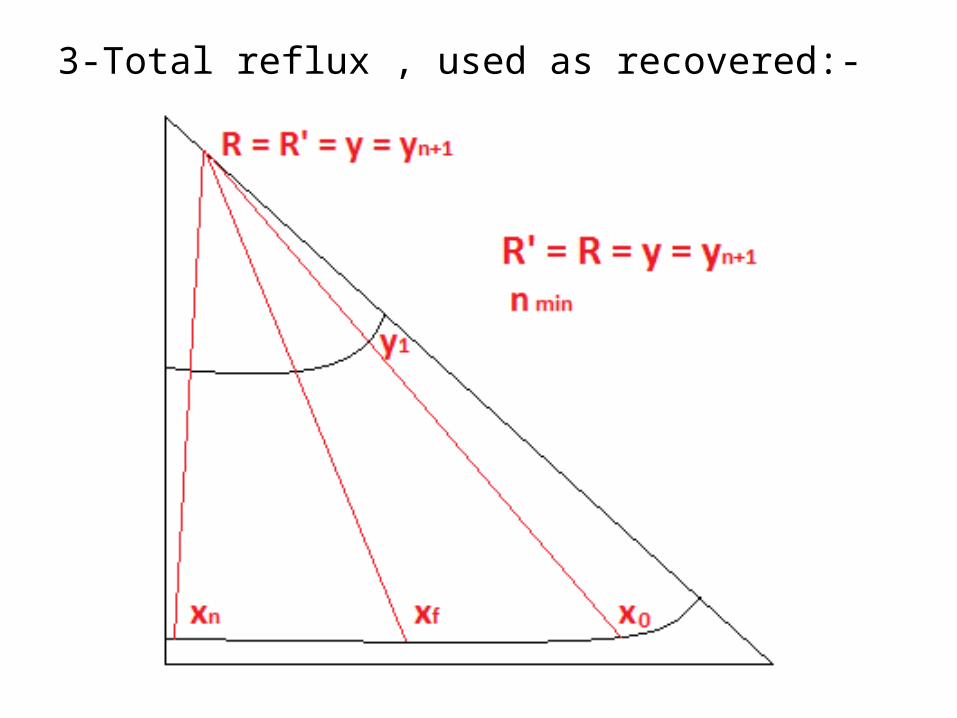
3-Total reflux , used as recovered:-
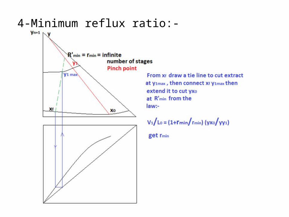
4-Minimum reflux ratio:-
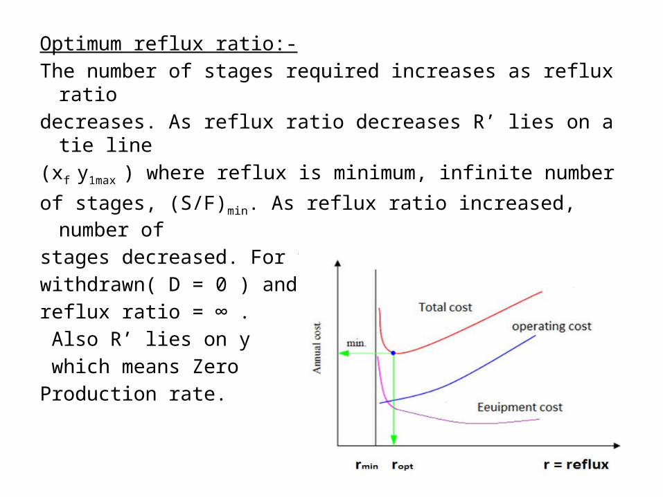
Optimum reflux ratio:-The number of stages required increases as reflux ratiodecreases. As reflux ratio decreases R’ lies on a tie line(xf y1max ) where reflux is minimum, infinite number
of stages, (S/F)min. As reflux ratio increased, number of
stages decreased. For total reflux, no product iswithdrawn( D = 0 ) andreflux ratio = ∞ . Also R’ lies on y which means ZeroProduction rate.
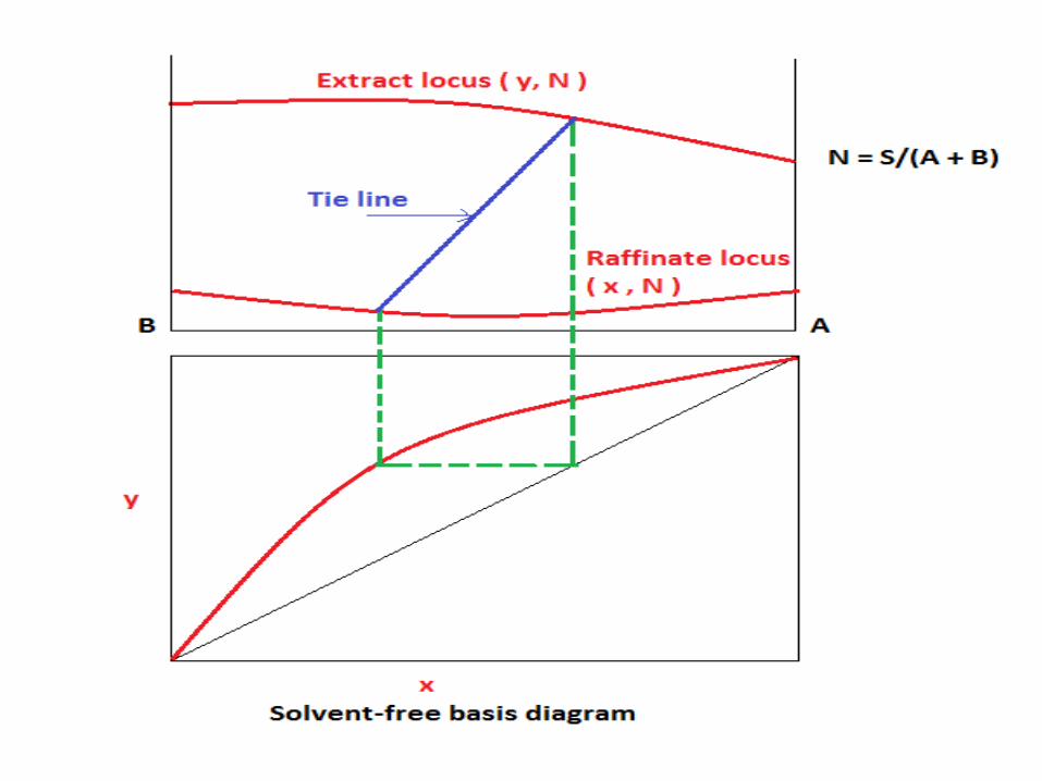
Solvent-free coordinate:-Solvent free coordinates can be used in designing solvent extraction systems. The construction is in general less crowded than in the case of triangular diagram, but the same procedure described above maybe followed. The amounts of various streams should beexpressed on solvent -free basis.

Some notes on the diagram:-
Pure A = 100% , B = 0 , S = 0
A A S 0x or y = = = 1 , N = 0
A + B A + 0 A + B 100 0
Pure B = 100% , A = 0 , S = 0
A 0 0x or y = = = 0 , N =
A + B 0 + 100 A + B 0 10
S
00
Pure S = 100% , A = 0 , B = 0
A 0 S 100x or y = = , N =
A + B 0 A + B 0 0
0
0
0 0
0
0
0
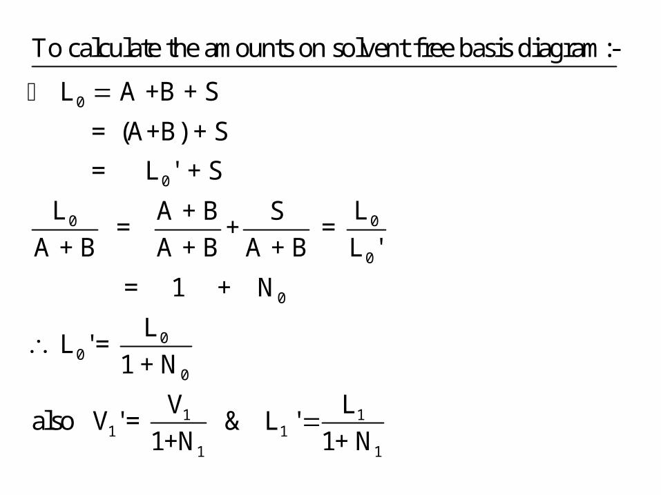
To calculate the amounts on solvent free basis diagram:-
L A +B + S
= (A+B) + S
= L ' + S
L LA + B S = + =
A + B A + B A + B L '
= 1 + N
L ' =
0
0
1 11 1
1 1
L 1 + N
V Lalso V ' = & L '
1+N 1+ N

'0 1
0 '1 0
'0 1
' '1 0
'01
'0 1
x R' VR' is located on x y so that =
R' y L
x y V & The ratio of =
y y L + D
x yV r + 1thus:- = ( )
L r y y
The operating lines of the two sections is projected down
to x-y digram and number of stages are determined by the
usual step-wise construction.
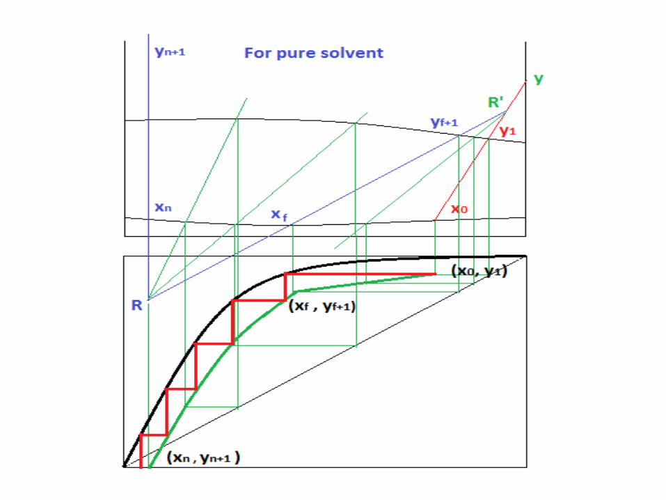

Special cases:-1- Solvent used as recovered → y = yn+1
(not pure Solvent)
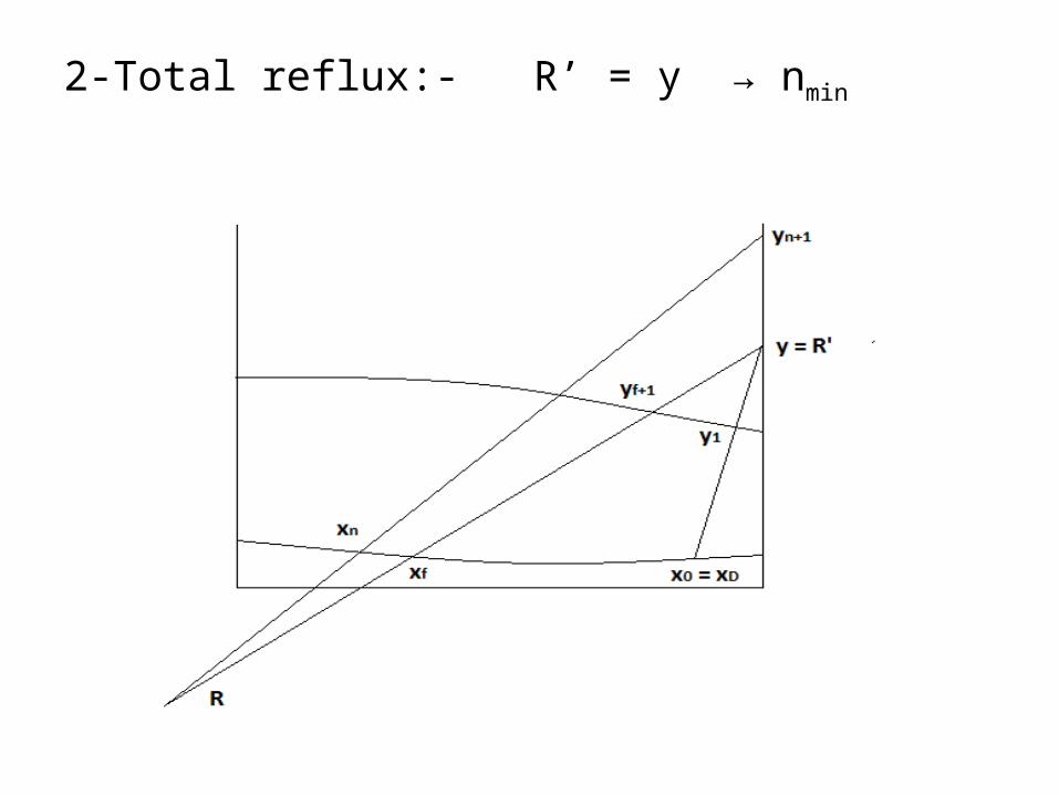
2-Total reflux:- R’ = y → nmin

3- Solvent used as recovered & total reflux (in case of pure solvent)→ n min
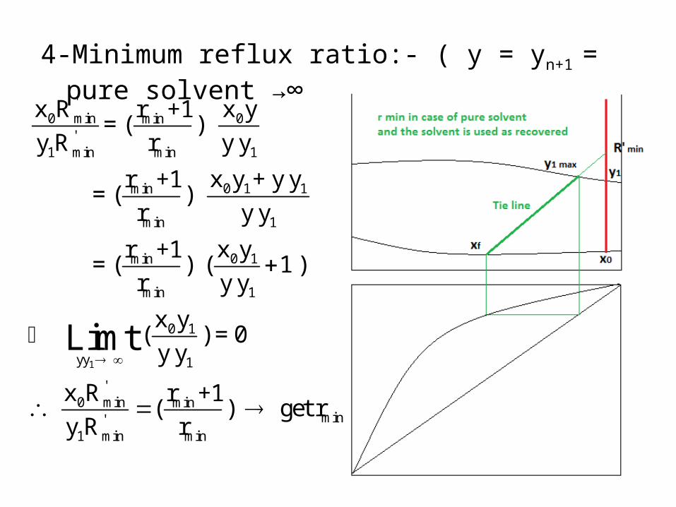
4-Minimum reflux ratio:- ( y = yn+1 = pure solvent →∞ )
1
'0 min 0min
'1 min min 1
0 1 1min
min 1
0 1min
min 1
0 1
yy 1
'0 min min
min'1 min min
x R x yr +1= ( )
y R r y y
x y + y yr +1 = ( )
r y y
x yr +1 = ( ) ( 1 )
r y y
x y ( ) = 0
y y
x R r +1 ( ) get r
y R r
Limt
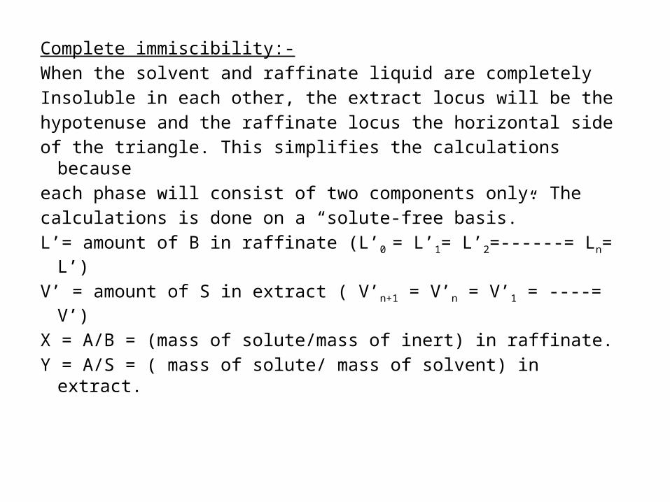
Complete immiscibility:-When the solvent and raffinate liquid are completelyInsoluble in each other, the extract locus will be thehypotenuse and the raffinate locus the horizontal side of the triangle. This simplifies the calculations becauseeach phase will consist of two components only. Thecalculations is done on a “solute-free basis.”L’= amount of B in raffinate (L’0 = L’1= L’2=------= Ln= L’)
V’ = amount of S in extract ( V’n+1 = V’n = V’1 = ----= V’)
X = A/B = (mass of solute/mass of inert) in raffinate.Y = A/S = ( mass of solute/ mass of solvent) in extract.
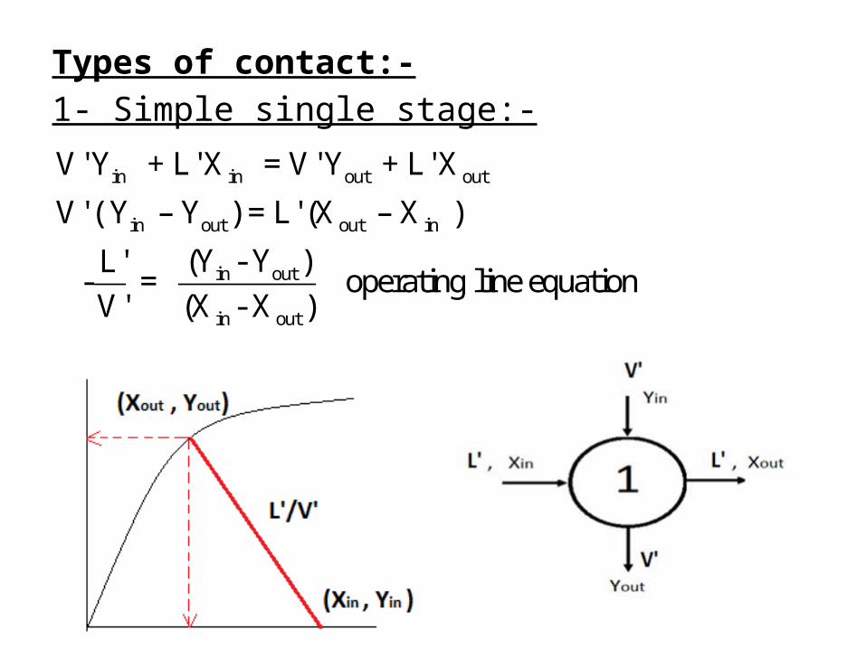
Types of contact:-1- Simple single stage:-
in in out out
in out out in
in out
in out
V' Y + L' X = V' Y + L' X
V' ( Y – Y ) = L' (X – X )
(Y - Y )L' - = operating line equation
V' (X - X )
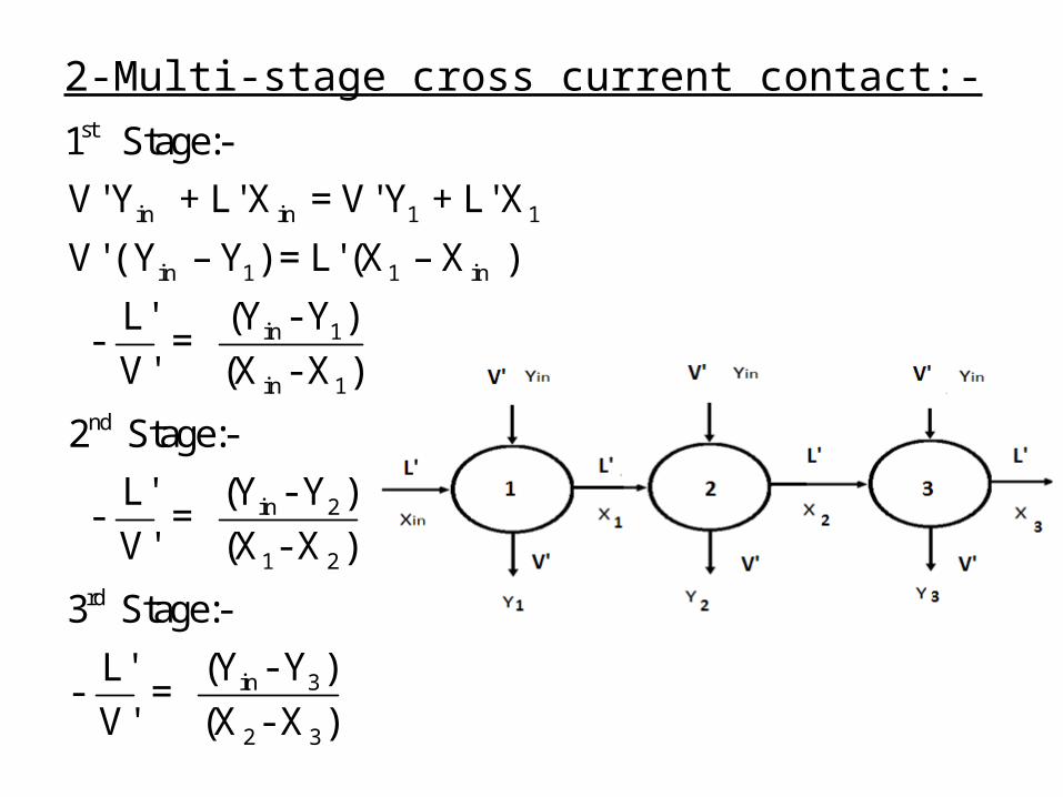
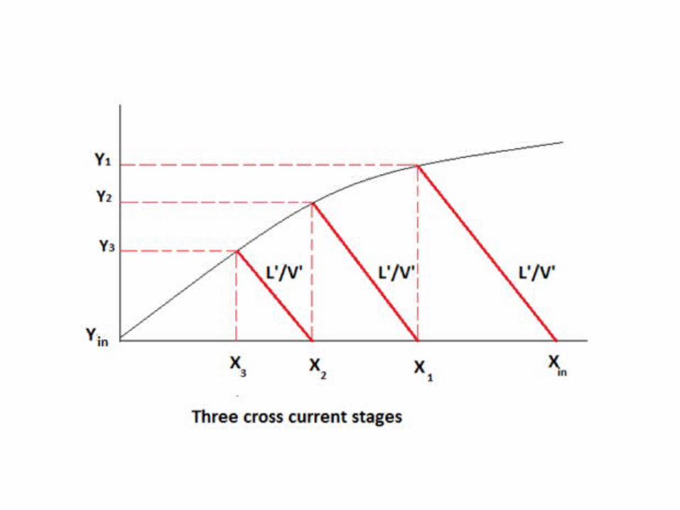
2-Multi-stage cross current contact:-st
in in 1 1
in 1 1 in
in 1
in 1
nd
in 2
1 2
rd
in 3
2 3
1 Stage:-
V' Y + L' X = V' Y + L' X
V' ( Y – Y ) = L' (X – X )
(Y - Y )L' - =
V' (X - X )
2 Stage:-
(Y - Y )L' - =
V' (X - X )
3 Stage:-
(Y - Y )L'- =
V' (X - X )
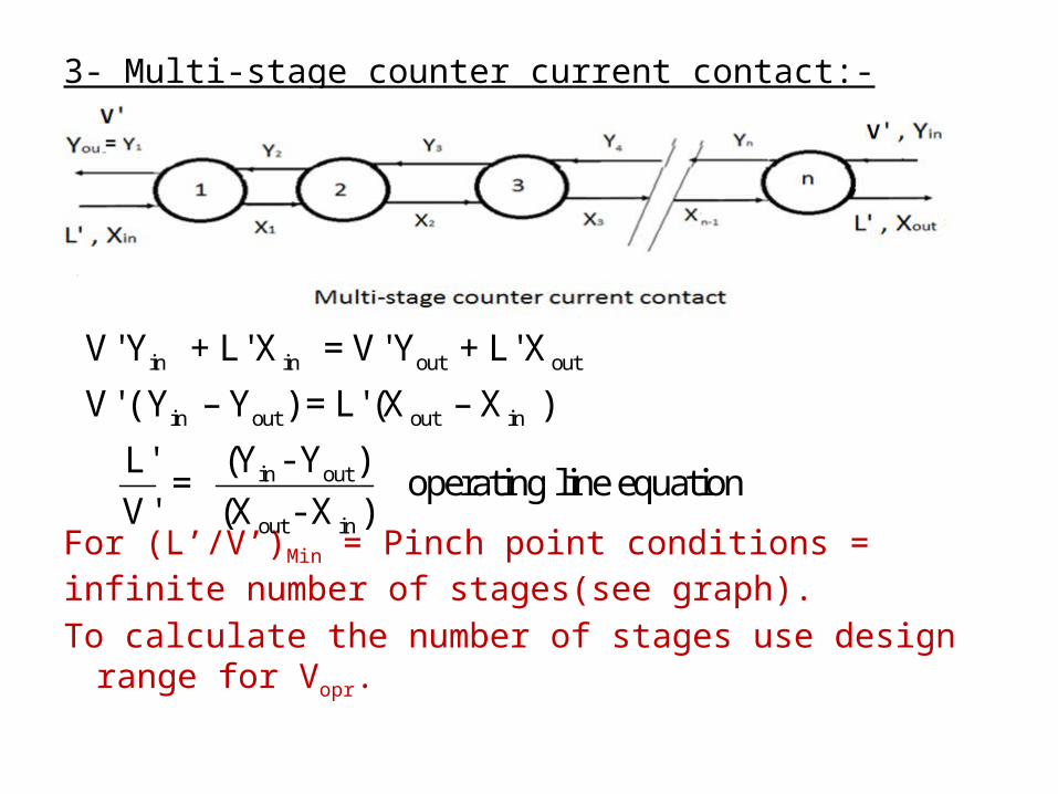
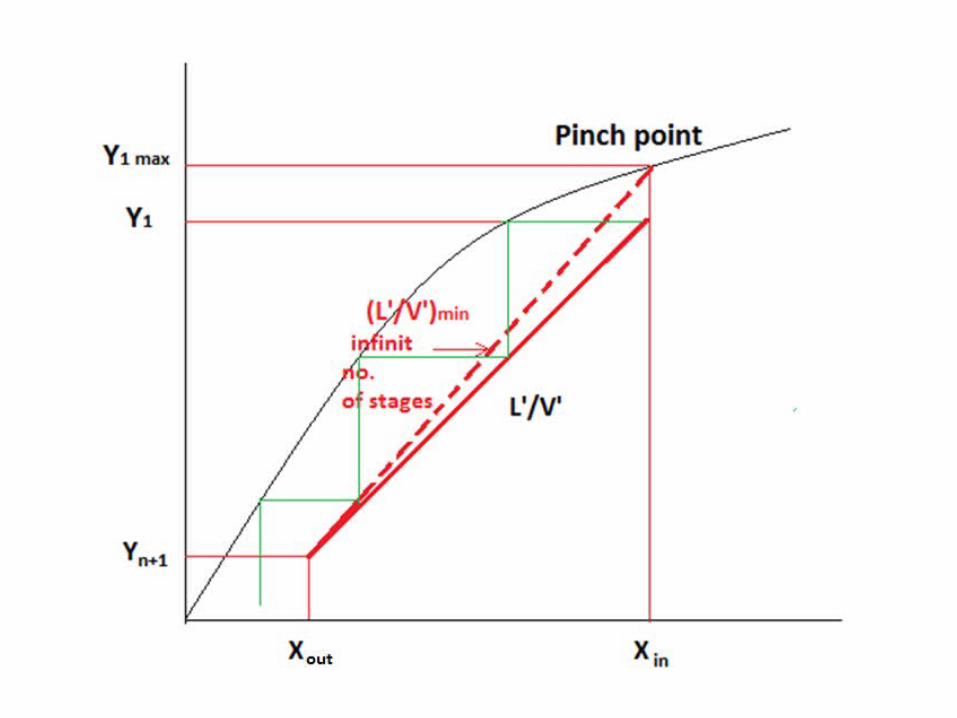
3- Multi-stage counter current contact:-
For (L’/V’)Min = Pinch point conditions = infinite number of stages(see graph).To calculate the number of stages use design range for Vopr.
in in out out
in out out in
in out
out in
V' Y + L' X = V' Y + L' X
V' ( Y – Y ) = L' (X – X )
(Y - Y )L' = operating line equation
V' (X - X )

Equipments in liquid extraction:-can be classified according to the methods applied for inter-dispersing the phases and producing the counter-current flow pattern.
Both of these can be achieved either by force of gravity acting on the density difference between the phases, or by applying centrifugal force.
The "gravity method" can be further divided into 2 broad categories according to the nature of their operation, namely stage-wise contact (e.g. in mixer settler) and differential contact (spray or packed column).
In commercial applications, distinction is normally made between the light phase and the heavy phase, and between the dispersed phase and the continuous phase. The choice of the dispersed phase depends on flow rates, viscosities and wetting characteristics of both phases and is usually based on experience. For example, depending on circumstances, the solvent can be the heavy phase or the continuous phase -- but it will always be the extract phase.


The location of the principal interface between the extract and the raffinate depends upon which phase is dispersed. When the light phase is dispersed, the interface is located at the top of the extractor. When the heavy phase is dispersed, the interface is located at the bottom. Normally the raffinate and/or extract needs to be separated by other means.


Examples of Extraction Equipment some of the following equipment will be briefly discussed :(1) Mixer-settler:- Mixer-settlers are still widely used because of their reliability, operating flexibility, and high capacity. They can handle difficult-to-disperse systems, such as those having high interfacial tension and/or large phase density difference. They can also used with highly viscous liquids and solid-liquid slurries. The main disadvantages are their size and the inventory of material held up in the equipment. For multiple unit operations, considerable capital costs may be needed for pumping and piping.
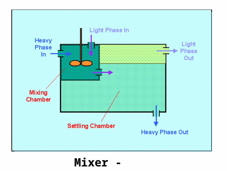
Mixer - Settler
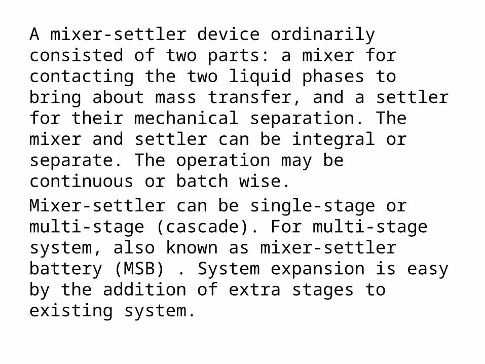
A mixer-settler device ordinarily consisted of two parts: a mixer for contacting the two liquid phases to bring about mass transfer, and a settler for their mechanical separation. The mixer and settler can be integral or separate. The operation may be continuous or batch wise.Mixer-settler can be single-stage or multi-stage (cascade). For multi-stage system, also known as mixer-settler battery (MSB) . System expansion is easy by the addition of extra stages to existing system.
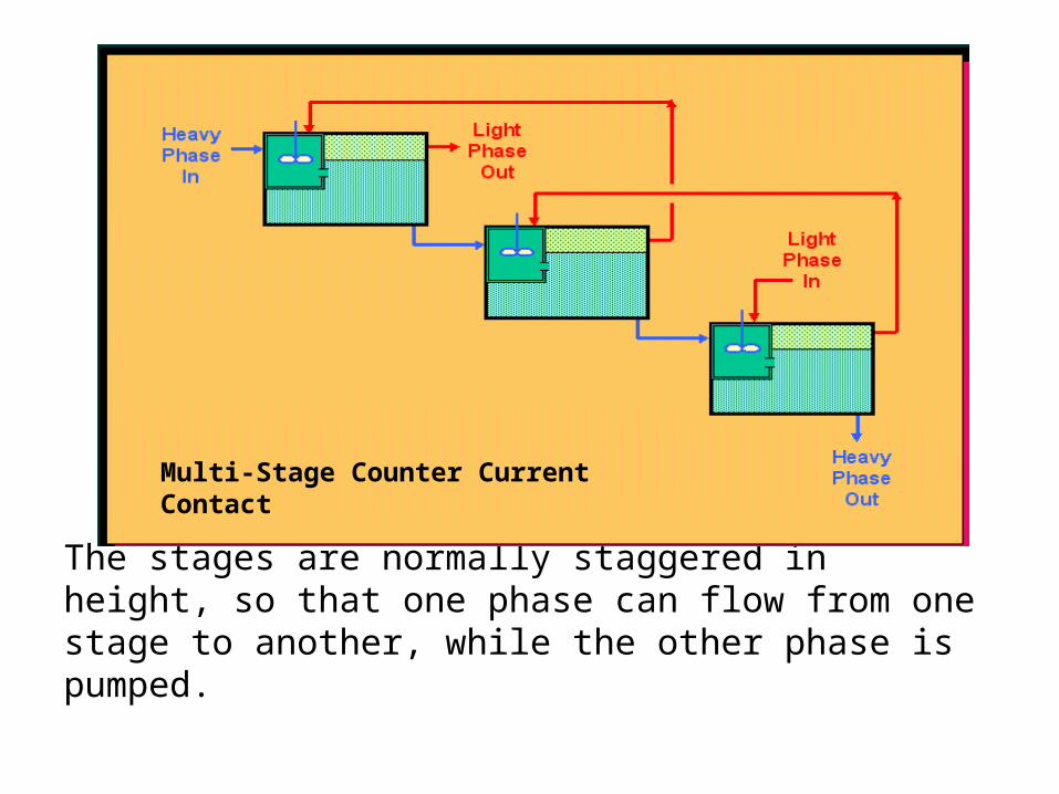
The stages are normally staggered in height, so that one phase can flow from one stage to another, while the other phase is pumped.
Multi-Stage Counter Current Contact

Unagitated Column Extractors showed 3 types of unagitated column extractors:
SPRAY COLUMN

Column extractors typically have the two phases flowing in countercurrent pattern. For the unagitated units shown the light phase being dispersed or distributed (hence the heavy phase continuous), i.e. the light liquid enters at the bottom of the column and evolve as small droplets at the nozzle distributor. The droplets of light liquid rise through the mass of heavier liquid, which flows downward as a continuous stream. The droplets are collected at the top and form the stream of light liquid leaving the top of the column. The heavy liquid on the other hand leaves the bottom of the column. The choice may be reversed, whereby the heavy stream is introduced into the light phase at the top of the column and falls as dispersed droplets through a continuous stream of light liquid.

(1) Spray ColumnThis set-up consists of an empty shell with provisions at the end for introducing and removing the liquids. Its construction is the simplest but suffers from low efficiency due to poor phase contacting and excessive back-mixing in the continuous phase. Because of their simple construction, spray columns are still used in the industry for simple operations such as washing and neutralization.
(2) Packed Column:-The packing in extraction is similar to the ones used in distillation. They include both random and structured packing. Packing offer better efficiency because of improved contacting and reduced back-mixing. It is important that the packing material be wetted by the continuous phase to avoid coalescence of the dispersed phase. To reduce the effects of channeling, re-distribution of the liquids at fixed intervals is normally required in taller columns.
(3) Sieve-Tray (Perforated-Plate) Multi-Stage Column:-This is also an improvement over the spray column. It is particularly suitable for corrosive systems where absence of mechanical moving parts is an advantage. Either the heavy liquid or the light liquid may be dispersed. If the light phase is dispersed, the light liquid flows through the perforations of each plate and is dispersed into drops which rise through the continuous phase. The continuous phase flows horizontally across each plate and passes to the plate below through the down comer
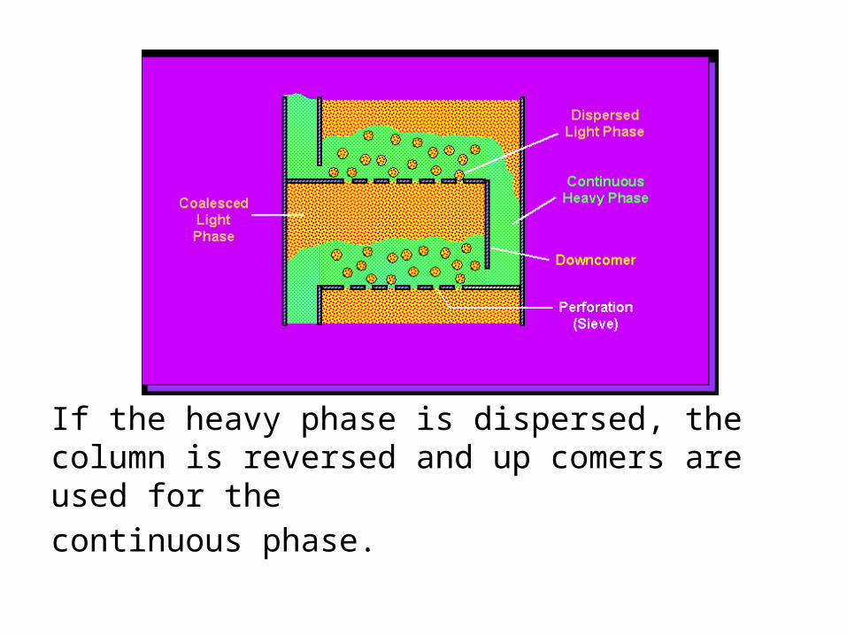
If the heavy phase is dispersed, the column is reversed and up comers are used for thecontinuous phase.
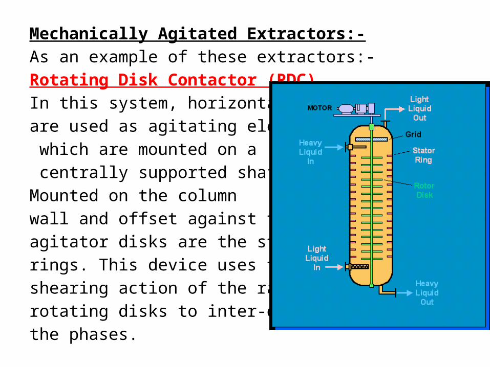
Mechanically Agitated Extractors:-As an example of these extractors:-Rotating Disk Contactor (RDC)In this system, horizontal disks are used as agitating elements, which are mounted on a centrally supported shaft. Mounted on the column wall and offset against the agitator disks are the stator rings. This device uses the shearing action of the rapidly rotating disks to inter-disperse the phases.