solstice enterprise manager(tm) 4.1 management … · 4.4.5 using em_topo_args for third party...
TRANSCRIPT

Sun Microsystems, Inc.901 San Antonio Road
Palo Alto, CA 94303U.S.A. 650-960-1300
Management Information Server (MIS)Guide
Solstice Enterprise Manager ™ 4.1
Part No. 806-7968-10October 2001, Revision A

Please
Recycle
Copyright 2001 Sun Microsystems, Inc., 901 San Antonio Road, Palo Alto, California 94303 U.S.A. All rights reserved.
This product or document is protected by copyright and distributed under licenses restricting its use, copying, distribution, and
decompilation. No part of this product or document may be reproduced in any form by any means without prior written authorization
of Sun and its licensors, if any. Third-party software, including font technology, is copyrighted and licensed from Sun suppliers.
Parts of the product may be derived from Berkeley BSD systems, licensed from the University of California. UNIX is a registered
trademark in the U.S. and other countries, exclusively licensed through X/Open Company, Ltd.
Sun, Sun Microsystems, the Sun logo, Solstice, Solstice Enterprise Manager, SunDocs, SunExpress,SunOS, and Solaris are trademarks,
registered trademarks, or service marks of Sun Microsystems, Inc. in the U.S. and other countries. All SPARC trademarks are used
under license and are trademarks or registered trademarks of SPARC International, Inc. in the U.S. and other countries. Products
bearing SPARC trademarks are based upon an architecture developed by Sun Microsystems, Inc.
The OPEN LOOK and Sun™ Graphical User Interface was developed by Sun Microsystems, Inc. for its users and licensees. Sun
acknowledges the pioneering efforts of Xerox in researching and developing the concept of visual or graphical user interfaces for the
computer industry. Sun holds a non-exclusive license from Xerox to the Xerox Graphical User Interface, which license also covers Sun’s
licensees who implement OPEN LOOK GUIs and otherwise comply with Sun’s written license agreements.
RESTRICTED RIGHTS: Use, duplication, or disclosure by the U.S. Government is subject to restrictions of FAR 52.227-14(g)(2)(6/87)
and FAR 52.227-19(6/87), or DFAR 252.227-7015(b)(6/95) and DFAR 227.7202-3(a).
DOCUMENTATION IS PROVIDED “AS IS” AND ALL EXPRESS OR IMPLIED CONDITIONS, REPRESENTATIONS AND
WARRANTIES, INCLUDING ANY IMPLIED WARRANTY OF MERCHANTABILITY, FITNESS FOR A PARTICULAR PURPOSE
OR NON-INFRINGEMENT, ARE DISCLAIMED, EXCEPT TO THE EXTENT THAT SUCH DISCLAIMERS ARE HELD TO BE
LEGALLY INVALID.
Copyright 2001 Sun Microsystems, Inc., 901 San Antonio Road, Palo Alto, Californie 94303 Etats-Unis. Tous droits réservés.
Ce produit ou document est protégé par un copyright et distribué avec des licences qui en restreignent l’utilisation, la copie, la
distribution, et la décompilation. Aucune partie de ce produit ou document ne peut être reproduite sous aucune forme, par quelque
moyen que ce soit, sans l’autorisation préalable et écrite de Sun et de ses bailleurs de licence, s’il y en a. Le logiciel détenu par des tiers,
et qui comprend la technologie relative aux polices de caractères, est protégé par un copyright et licencié par des fournisseurs de Sun.
Des parties de ce produit pourront être dérivées des systèmes Berkeley BSD licenciés par l’Université de Californie. UNIX est une
marque déposée aux Etats-Unis et dans d’autres pays et licenciée exclusivement par X/Open Company, Ltd.
Sun, Sun Microsystems, le logo Sun, Solstice, Solstice Enterprise Manager, SunDocs, SunExpress, SunOS, et Solaris sont des marques
de fabrique ou des marques déposées, ou marques de service, de Sun Microsystems, Inc. aux Etats-Unis et dans d’autres pays. Toutes
les marques SPARC sont utilisées sous licence et sont des marques de fabrique ou des marques déposées de SPARC International, Inc.
aux Etats-Unis et dans d’autres pays. Les produits portant les marques SPARC sont basés sur une architecture développée par Sun
Microsystems, Inc.
L’interface d’utilisation graphique OPEN LOOK et Sun™ a été développée par Sun Microsystems, Inc. pour ses utilisateurs et licenciés.
Sun reconnaît les efforts de pionniers de Xerox pour la recherche et le développement du concept des interfaces d’utilisation visuelle
ou graphique pour l’industrie de l’informatique. Sun détient une licence non exclusive de Xerox sur l’interface d’utilisation graphique
Xerox, cette licence couvrant également les licenciés de Sun qui mettent en place l’interface d’utilisation graphique OPEN LOOK et qui
en outre se conforment aux licences écrites de Sun.
CETTE PUBLICATION EST FOURNIE "EN L’ETAT" ET AUCUNE GARANTIE, EXPRESSE OU IMPLICITE, N’EST ACCORDEE, Y COMPRIS
DES GARANTIES CONCERNANT LA VALEUR MARCHANDE, L’APTITUDE DE LA PUBLICATION A REPONDRE A UNE UTILISATION
PARTICULIERE, OU LE FAIT QU’ELLE NE SOIT PAS CONTREFAISANTE DE PRODUIT DE TIERS. CE DENI DE GARANTIE NE
S’APPLIQUERAIT PAS, DANS LA MESURE OU IL SERAIT TENU JURIDIQUEMENT NUL ET NON AVENU.
Contents
Preface xiii
1. Introduction 1-1
1.1 What is the MIS? 1-1
1.2 MIS Concepts 1-3
1.2.1 Network Resources as Objects 1-3
1.2.2 Objects and Applications 1-5
1.2.3 Agents 1-6
1.2.4 Management Requests 1-6
1.2.5 Remote or Collaborating MISs 1-6
1.3 Components 1-7
1.3.1 Event Distribution System 1-7
1.3.2 Naming Service 1-9
1.3.3 New Application Entity Title Format 1-11
1.3.4 Portable Management Interface 1-12
1.3.5 Management Protocol Adaptors 1-13
1.3.5.1 CMIP MPA 1-13
1.3.5.2 SNMP MPA 1-13
1.3.5.3 RPC Management Protocol Adaptor 1-13
1.3.5.4 Other Management Protocol Adaptors 1-13
1.3.6 Management Information Tree 1-14
1.3.6.1 MIT Object Naming 1-15
1.3.6.2 Name Binding 1-16
Contents iii

1.3.6.3 Name Types 1-17
1.3.6.4 MIT Organization and Standards 1-18
1.3.7 Metadata Repository 1-18
1.3.8 Nerve Center 1-19
1.3.9 Alarm Service Module 1-19
1.3.10 Data Logging and Storage Module 1-19
1.3.11 Compilers 1-20
1.3.12 Message Routing Module 1-20
1.3.13 Object Access Module 1-20
1.3.14 UNIX Processes (Daemons) 1-21
2. Operating MIS 2-1
2.1 Starting MIS 2-1
2.1.1 After a New Installation 2-2
2.1.2 Under Normal Conditions 2-2
2.1.3 After a System Failure 2-2
2.1.4 After a System Reboot 2-3
2.1.5 Reintializing the Database 2-3
2.1.6 Recreating the Database 2-4
2.1.7 Options and Commands for em_services 2-5
2.2 Monitoring the Daemon Processes 2-7
2.2.1 Starting the Process Monitor 2-7
2.2.2 Stopping the Process Monitor 2-8
2.2.3 Monitor Timeouts 2-8
2.2.4 Configuring Escalation Actions 2-8
2.3 Shutting Down MIS 2-10
2.3.1 In Normal Mode 2-10
2.3.2 Using Emergency Mode to Shut Down MIS 2-11
3. Accessing a Remote MIS 3-1
3.1 Implementing a Multiple-MIS Architecture 3-1
iv Management Information Server (MIS) Guide • October 2001

3.2 Comparing MIS-to-MIS Examples 3-2
3.2.1 Accessing Objects Without an MIS-to-MIS Connection 3-3
3.2.2 Accessing Managed Objects With an MIS-to-MIS Connection 3-4
3.3 Establishing MIS Connections 3-7
3.4 Sharing Data Between Connected MISs 3-8
3.4.1 Accessing Data About All Events 3-9
3.4.2 Accessing Data about Selected Events 3-10
3.5 Re-establishing a Remote MIS Link 3-11
4. Managing MIS 4-1
4.1 Setting Up MIS on Your Network 4-1
4.2 Controlling Access 4-2
4.3 Customizing the MIS Configuration 4-2
4.4 Starting MPAs 4-2
4.4.1 Starting CMIP 4-2
4.4.1.1 Registering CMIP Agents 4-3
4.4.1.2 Configuring 4-4
4.4.2 Starting RPC and SNMP 4-6
4.4.3 Starting MPAs on a Remote Machine 4-6
4.4.4 Stopping MPAs 4-9
4.4.5 Using em_topo_args for Third Party Integration 4-10
4.5 Detecting Events and Conditions 4-10
4.6 Troubleshooting 4-10
5. Backing Up/Restoring andExporting/Importing Data 5-1
5.1 Guidelines for Backing up and Restoring Data 5-1
5.1.1 Testing Your Backups 5-2
5.1.2 Preparing for Backup 5-2
5.1.3 Backing up and Restoring Network Views Data and Agents 5-3
5.1.4 Supporting Migration Paths 5-4
Contents v

5.1.5 Copying Network Views and Agent Data 5-5
5.1.6 Using Solstice Backup and Restore 5-8
5.2 Guidelines for Importing and Exporting Data 5-8
5.2.1 What is Exported? 5-9
5.2.2 What is Not Exported? 5-9
5.3 Exporting Network View Data 5-10
5.3.1 Exporting and Importing Log Records 5-11
5.4 Converting Legacy Data 5-12
6. Managing Event Logs 6-1
6.1 Logging Event Files 6-1
6.2 Using Event Logging 6-2
6.2.1 Logging Services 6-2
6.2.2 Non-Default Location of Logs 6-4
6.3 Creating and Instantiating Logs 6-5
6.4 Creating and Defining Events to be Logged 6-6
6.5 Logging Received Events 6-9
6.6 Logging Historical Records 6-9
6.6.1 Enabling Historical Logging 6-10
6.6.2 Logging Historical Log Files 6-10
6.6.2.1 Configuration File 6-11
6.6.2.2 Database Schema Definition File 6-12
6.6.2.3 Database Schema Mapping 6-17
6.6.2.4 Database Tables 6-18
6.6.2.5 Database Schema Parser 6-25
6.7 Merging Log Records from Different Databases 6-26
7. Obtaining Data From the Database 7-1
7.1 Prerequisite Knowledge 7-1
7.2 Querying the Database 7-1
7.3 Using Third-Party Software 7-3
vi Management Information Server (MIS) Guide • October 2001

8. Adding New Data Definitions 8-1
8.1 Adding a MIB 8-2
8.2 Adding SunNet Manager Schemas 8-3
8.3 Adding Managed Object Classes 8-5
8.3.1 Defining the Properties of an MOC 8-6
8.3.1.1 Sample GDMO File 8-7
8.3.1.2 Sample ASN.1 Definition File 8-9
8.3.2 Loading an MOC into MIS 8-10
8.4 Configuring Notifications for Managed Objects That Reside in the Solstice
EM MIS 8-11
8.4.1 Comments 8-11
8.4.2 Format of a CREATE Entry 8-12
8.4.3 Format of a DELETE Entry 8-13
8.4.4 Format of a SET Entry 8-13
8.4.5 Adding Event Types 8-14
8.5 Creating GDMO Documents for New Events 8-15
8.6 Logging New Event Types 8-16
8.7 Loading a New Event Type 8-17
8.7.1 Loading Data Definitions 8-18
A. Database Schema A-1
A.1 Database Schema Mapping A-1
A.2 Database Tables A-3
A.3 Database Schema Parser A-14
B. Management Information Tree (MIT) B-1
B.1 Management Information Tree Objects B-1
B.1.1 Object Descriptions B-2
B.1.2 Adding a New Managed Object to the MDR B-2
B.1.3 Compiling Definitions for the MDR B-3
B.2 Compilers B-3
Contents vii

B.2.1 The ASN.1 Compiler B-3
B.2.1.1 Compiling ASN.1 Documents B-4
B.2.2 The GDMO Compiler B-5
B.2.2.1 GDMO Updates B-5
B.2.2.2 GDMO Compiler Input B-6
B.2.2.3 Managing Related GDMO Documents B-7
B.2.2.4 GDMO Compiler Output B-7
B.3 Command Line Syntax for em_gdmo B-8
B.3.1 Parse-only Operation B-9
B.3.2 Parse-and-Compile Operation B-9
B.4 The Concise MIB Compiler B-10
B.4.1 Names of Input and Output Files B-12
B.4.2 Command Line Syntax for em_cmib2gdmo B-13
B.4.3 Diagnostics B-14
B.5 The Schema Compiler B-15
B.5.1 Command Line Syntax for em_snm2gdmo B-15
B.6 Invoking the Compilers B-17
B.6.1 To Invoke the ANS.1 Compiler B-17
B.6.2 To Invoke the em_compose_oc Command B-18
B.6.3 The em_cmib2gdmo Command B-19
B.6.4 The em_gdmo Command B-19
B.6.5 The em_load_name_bindings Command B-20
B.6.6 The em_snm2gdmo Command B-20
B.6.7 The em_topo_args Command B-21
viii Management Information Server (MIS) Guide • October 2001

Figures
FIGURE 1-1 MIS Architecture 1-2
FIGURE 1-2 Network Views Window 1-4
FIGURE 1-3 How Applications Access the MIS Data 1-5
FIGURE 1-4 Event Flow 1-8
FIGURE 1-5 Name Service Components 1-10
FIGURE 1-6 Name Services Message Flows 1-11
FIGURE 1-7 Management Information Tree 1-14
FIGURE 1-8 Naming Schema in Multiple MIS Architecture 1-15
FIGURE 1-9 GDMO and ANS1 Compilers Update the MDR 1-18
FIGURE 3-1 Two Unconnected MISs 3-3
FIGURE 3-2 MITs of Two Connected MISs 3-4
FIGURE 3-3 Local and Remote Objects as Seen from MIS Net 1 3-5
FIGURE 3-4 Local and Remote Objects as Seen From MIS Net 2 3-6
FIGURE 3-5 Objects Seen From MIS Net 3 3-6
FIGURE 3-6 MIS Connections Window 3-9
FIGURE 3-7 MIS Connections Advanced Settings Window 3-10
FIGURE 4-1 Security Window 4-7
FIGURE 4-2 Security Defaults Window 4-8
FIGURE 5-1 Backup and Restore Window 5-2
Figures ix

FIGURE 5-2 Network View Import and Export Window 5-10
FIGURE 6-1 Event Log Management Activities 6-2
FIGURE 6-2 Entity Relationship Model for Log Record Database 6-18
FIGURE 8-1 Managed Object Implementation Components 8-5
FIGURE B-1 The Concise MIB Compiler B-12
x Management Information Server (MIS) Guide • October 2001

Tables
TABLE 1-1 AE-title Formats 1-11
TABLE 1-2 AE-title Fields 1-12
TABLE 1-3 Processes in a UNIX Environment 1-21
TABLE 2-1 Commands for the em_services 2-6
TABLE 2-2 Optional Parameters for the em_services Command 2-6
TABLE 3-1 Optional Parameters for the em_mismgr Command 3-7
TABLE 4-1 Field Description for CMIP 4-5
TABLE 5-1 Commands for Exporting Data 5-6
TABLE 5-2 Command Line Options for em_imex 5-12
TABLE 6-1 Log Object Attributes 6-3
TABLE 6-2 Default Alarm Types and Log Record Types 6-7
TABLE 6-3 Sample Master List of Tables 6-19
TABLE 6-4 Sample attributeValueChangeRecord 6-20
TABLE 6-5 eventLog 6-20
TABLE 6-6 objectCreationRecord 6-21
TABLE 6-7 objectDeletionRecord 6-21
TABLE 6-8 emAlarmRecord 6-22
TABLE 6-9 attributeValueChangeRecord 6-23
TABLE 6-10 relationshipChangeRecord 6-23
xi

TABLE 6-11 emInternetAlarmRecord 6-23
TABLE 6-12 nerveCenterAlarmRecord 6-24
TABLE 8-1 Valid Values for <create_notif_config_value> 8-12
TABLE 8-2 Valid Values for <delete_notif_config_value> 8-13
TABLE 8-3 Valid Values for set_notif_config_value 8-13
TABLE 8-4 Event Notifications in Solstice EM 8-15
TABLE 8-5 Default Mapping of Notifications to Event Log Records 8-16
TABLE 8-6 Load Data Definitions Dialog Items 8-18
xii Management Information Server (MIS) Guide • July 2001

Preface
This Guide provides information and instructions for administrating the Solstice
Enterprise Manager (Solstice EM) Management Information Server (MIS).
Who Should Use This Guide
This guide is for system, network, and database administrators who are responsible
for maintaining the Solstice EM MIS and database.
In this guide you will find the topics and tasks most central to administrating the
MIS. Detailed instructions for using related applications, tools, and Solstice EM
features are in other publications within the Solstice EM documentation set.
How This Guide Is Organized
Chapter 1 “Introduction” is an overview of the MIS in Solstice EM. This chapter is
recommended reading for new administrators and administrators who are new to
the Solstice EM product.
Chapter 2 “Operating MIS” provides instructions for starting, monitoring the
daemon processes, and shutting down the MIS. Included in this chapter are
instructions for starting the MIS after installation and when there are problems with
data in the database.
Chapter 3 “Accessing a Remote MIS” details how to set up communication between
a local and remote MIS. It includes explanations and examples that help you decide
when to implement a multiple-MIS architecture.
Preface xiii

Chapter 4 “Managing MIS” provides information and procedures for performing
tasks that will help you effectively manage your MIS.
Chapter 5 “Backing Up/Restoring and Exporting/Importing Data” contains
guidelines for backing up and restoring your database, network view, and agent
data. Also, it provides instructions for exporting and importing data.
Chapter 6 “Managing Event Logs” contains information about how the MIS
performs log management.
Chapter 7 “Obtaining Data From the Database” provides instructions for
performing database queries.
Chapter 8 “Adding New Data Definitions” contains procedures for adding new
event types and managed object classes. Also included are instructions for
converting Sun Management Information Bases (MIB) and SunNet Manager schema
to GDMO defined managed object classes.
Appendix A “Database Schema” contains information on how the database is
structured and how log descriptions map or relate to the tables.
Appendix B “Management Information Tree (MIT)” provides a description of the
compilers provided with Solstice EM.
Related Books
Refer to the following books for additional information and, in some cases, detailed
instructions:
■ Customizing Guide■ Managing Your Network■ Troubleshooting Guide■ Developing C++ Application
xiv Management Information Server (MIS) Guide • October 2001

What Typographic Changes Mean
The following table describes the typographic conventions used in this guide.
Shell Prompts in Command Examples
The following table shows the default system prompt and superuser prompt for the
C shell, Bourne shell, and Korn shell.
TABLE P-1 Typographic Conventions
Typeface orSymbol Meaning Example
AaBbCc123 The names of commands, files,
and directories; on-screen
computer output
Edit your .login file.
Use ls -a to list all files.
machine_name% You have mail.
AaBbCc123 What you type, contrasted with
on-screen computer output
machine_name% suPassword:
<AaBbCc123> Command-line placeholder:
replace with a real name or value
To delete a file, type rm <filename>
AaBbCc123 Book titles, new words or terms,
or words to be emphasized
Read Chapter 6 in the User’s Guide.
These are called class options.
You must be root to do this.
TABLE P-2 Shell Prompts
Shell Prompt
C shell prompt machine_name%
C shell superuser prompt machine_name#
Bourne shell and Korn shell
prompt
$
Bourne shell and Korn shell
superuser prompt
#
xv

User Interface Conventions
The following subsections define the conventions used in this guide for describing
user interactions with the Graphical User Interface provided with Solstice EM.
Mouse/Menu Interactions
In the interest of clarity and brevity, we have streamlined the conventions used to
describe user interactions with the Solstice EM system. For example, the following is
a task description:
To exit, press the right mouse button on the File icon. In the pull-down menu that
you receive, move the mouse pointer down to Exit and release the right mouse
button.
And it would be condensed to the following:
To exit, select File ➔ Exit.
The symbol ➔ indicates movement to (selection of) the “level” or item indicated
after the symbol.
The Solstice EM Graphical User Interfaces (GUI) are, with the exception of the MIS
Objects tool, based on the standard Motif libraries. Therefore, the Motif conventions
for selecting and manipulating GUI objects—such as icons, menu items—hold true
for the Solstice EM interface.
The following table defines the conventions used in this guide to describe item
selection and activation.
TABLE P-3 User Interaction Equivalents
Complete Description As Described in this Document
Select an item by clicking once with the left mouse
button.
Select an item.
Activate an item by double-clicking with the left mouse
button.
Activate an item.
xvi Management Information Server (MIS) Guide • October 2001

Accessing Sun Documentation Online
The docs.sun.com sm web site enables you to access Sun technical documentation
on the Web. You can browse the docs.sun.com archive or search for a specific book
title or subject at http://docs.sun.com
Also, you can view the online documentation by pointing your browser to the
following URL, file:/opt/SUNWconn/em/docs/SEMDOCHP/index.html
Sun Welcomes Your Comments
Sun is interested in improving its documentation and welcomes your comments and
suggestions. You can send your comments by email to [email protected] .
Please include the part number of your document in the subject line of your email.
Press left on the slider in the scrollbar and move the
slider so that the item comes into view.
Scroll until the item comes into
view.
Press right on the icon to obtain the icon pulldown menu.
Move the mouse pointer over the item in the menu and
release the mouse button.
Select icon ➔ item.
orInvoke icon ➔ item.
Press and hold middle mouse button on the icon. Move
the mouse pointer to the target location and release the
mouse button.
Drag and drop.
TABLE P-3 User Interaction Equivalents (Continued)
Complete Description As Described in this Document
xvii

xviii Management Information Server (MIS) Guide • October 2001

CHAPTER 1
Introduction
This chapter introduces the Solstice Enterprise Manager (Solstice EM) Management
Information Server (MIS) and its components. If you are a new user, read this
chapter to understand the MIS concepts and components.
This chapter describes the following topics:
■ Section 1.1 “What is the MIS?” on page 1-1
■ Section 1.2 “MIS Concepts” on page 1-3
■ Section 1.3 “Components” on page 1-7
1.1 What is the MIS?In the Solstice EM environment, a Management Information Server (MIS) is a
machine hosting an object-oriented Structured Query Language (SQL) database
containing information about every component on your network that is managed by
Solstice EM. In this model, physical network components are represented as
managed objects in the MIS database.
The MIS is considered as the “heart” of Solstice EM. The MIS is not owned or
launched by applications that use its services. Rather, the MIS contributes a pool of
UNIX processes, often called daemons. These run continuously as background tasks
on one or more workstations.
In general terms, the MIS provides the following services:
■ Access control
■ Requests
■ Connections
■ Events and alarms
■ Logging
■ Object management
1-1

Functionally, the resources on the MIS can be divided into four general categories:
■ The MIS database containing information about the components on your
network.
■ The MIS Nerve Center that provides the logic and methods to actually do
something with the information in the MIS; the Nerve Center is the source of
requests and responses based on network conditions.
■ Portable Management Interface (PMI) APIs and Management Protocol Adapters
(MPAs).
■ A set of ancillary MIS services that make the information in the MIS database
available to network management applications and software agents.
For data security or logical convenience, you can use multiple MIS databases, with
one MIS database on each host. Multiple MIS databases can be linked so that all
appear as one database to a given user. For more information about linking multiple
MIS databases refer to the Customizing Guide.
FIGURE 1-1 MIS Architecture
In the above figure, a multiple MIS implementation distributes the management
information and processing, making the network more efficient. You can see, from
this example, how the MIS is the key module that enables users and applications to
deal with the scale and complexity of a large network systems environment.
1-2 Management Information Server (MIS) Guide • October 2001

That’s the big picture. To fully understand the MIS, read the following sections that
describe the concepts and components of the MIS.
If you are an experienced network administrator, engineer, or technical support user,
you are probably familiar with the MIS concepts and components. The information
most interesting to you may be the architecture and implementations within
Solstice EM. For users who are less experienced, the detailed information about
concepts and components is crucial for understanding what the MIS contributes to
Solstice EM.
1.2 MIS ConceptsThis section briefly describes the following concepts of the MIS:
■ Network resources as objects
■ Objects and applications
■ Agents
■ Management requests
■ Remote or collaborating MISs
1.2.1 Network Resources as Objects
One of the most important MIS concepts relates to how it manages resources. The
MIS keeps track of all resources by considering them as objects. The term managedobjects is used throughout Solstice EM to refer to objects managed by the MIS.
Graphical objects represent objects that reside in agents (remote objects). They
include hardware, software, static, and dynamic icons. The following figure
illustrates an example of these objects for a network.
Chapter 1 Introduction 1-3

A managed object refers to a physical device such as a workstation, a router, or a
hub. It can also represent logical entities such as a Local Area Network (LAN) or an
alarm log.
FIGURE 1-2 Network Views Window
Considering network resources as objects, the MIS manages activities and
information sent through the network. Also, the MIS manages information about
logical entities such as routing tables and printer queues. Objects include servers,
clients, hubs, routers, and other hardware and software resources that are part of
your network.
1-4 Management Information Server (MIS) Guide • October 2001

Because the MIS is a repository for all management data and functions, it makes
data about managed objects available to its clients, both applications and services.
The MIS provides an extensible set of management functions and an environment
for implementing and manipulating managed objects in your network.
1.2.2 Objects and Applications
Applications access the MIS object services by connecting to the MIS through a
Portable Management Interface (PMI), as shown in the following figure. The MIS
then makes data about managed objects available to applications.
From applications, users can create, delete, update, initiate action, register for events,
and request data about local or remote objects.
FIGURE 1-3 How Applications Access the MIS Data
App
MIS
MPA
MIS
App
Agent
MPA
PMI
PMI
PMI
PMI
PMI
Network ManagementProtocol
Chapter 1 Introduction 1-5
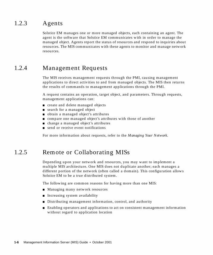
1.2.3 Agents
Solstice EM manages one or more managed objects, each containing an agent. The
agent is the software that Solstice EM communicates with in order to manage the
managed object. Agents report the status of resources and respond to inquiries about
resources. The MIS communicates with these agents to monitor and manage network
resources.
1.2.4 Management Requests
The MIS receives management requests through the PMI, causing management
applications to direct activities to and from managed objects. The MIS then returns
the results of commands to management applications through the PMI.
A request contains an operation, target object, and parameters. Through requests,
management applications can:
■ create and delete managed objects
■ search for a managed object
■ obtain a managed object’s attributes
■ compare one managed object’s attributes with those of another
■ change a managed object’s attributes
■ send or receive event notifications
For more information about requests, refer to the Managing Your Network.
1.2.5 Remote or Collaborating MISs
Depending upon your network and resources, you may want to implement a
multiple MIS architecture. One MIS does not duplicate another; each manages a
different portion of the network (often called a domain). This configuration allows
Solstice EM to be a true distributed system.
The following are common reasons for having more than one MIS:
■ Managing many network resources
■ Increasing system availability
■ Distributing management information, control, and authority
■ Enabling operators and applications to act on consistent management information
without regard to application location
1-6 Management Information Server (MIS) Guide • October 2001

Each remote or collaborating MIS routes management information to the managing
MIS. In an environment where two or more MISs need to exchange information,
transfer information, or act on behalf of one another, one MIS assumes the role of
manager when requesting information from another MIS.
There is no explicit MIS-MIS interface. One MIS communicates with another through
a PMI. The MIS locates the managed information and executes the request.
Solstice EM applications are multi-MIS aware, so that a user can access and
manipulate remote objects.
1.3 ComponentsThis section briefly describes the major components of the MIS. To make data about
network resources (managed objects) available to clients, the MIS uses the following
components:
■ Event Distribution System
■ Naming Service
■ New Application Entity Title Format
■ Portable Management Interface
■ Management Protocol Adaptors
■ Management Information Tree
■ MetaData Repository
■ Nerve Center
■ Alarm Service Module
■ Data Logging and Storage Module
■ Compilers
■ Message Routing Module
■ Object Access Module
■ Unix Processes (Daemons)
1.3.1 Event Distribution System
The Event Distribution System (EDS) provides event distribution to the Solstice EM
components. The EDS has three components:
■ Event source
■ Event distribution component
■ Event listener
Chapter 1 Introduction 1-7

EDS enables an event source to send events to the event listener. The event sources
send the events to the event distribution component. The event distribution
component performs the discriminator evaluation (a filter) of the events and
forwards the event listeners, if the events match the discriminator of the event
listeners.
The event distribution component maintains a list of discriminators for a list of
event listeners.
The event flow mechanism is illustrated in the following figure.
FIGURE 1-4 Event Flow
Event Source Event Source Event Source(ex: MIS) (ex: MPA) (ex: PMI program)
EventListener(ex: MIS)
EventListener
(ex: Network
EventListener
(ex: AlarmEventListener
(ex: MPA)
Other examples of Event Sources include:Topology ServerLog ServerSNMP Trap daemonSNM forward program
Event DistributionSystem
Manager)View Tool)
1-8 Management Information Server (MIS) Guide • October 2001
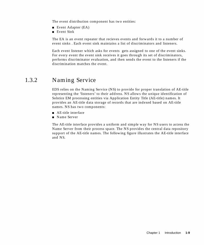
The event distribution component has two entities:
■ Event Adapter (EA)
■ Event Sink
The EA is an event repeater that recieves events and forwards it to a number of
event sinks . Each event sink maintains a list of discriminators and listeners.
Each event listener which asks for events gets assigned to one of the event sinks.
For every event the event sink receives it goes through its set of discriminators,
performs discriminator evaluation, and then sends the event to the listeners if the
discrimination matches the event.
1.3.2 Naming Service
EDS relies on the Naming Service (NS) to provide for proper translation of AE-title
representing the ‘listeners’ to their address. NS allows the unique identification of
Solstice EM processing entities via Application Entity Title (AE-title) names. It
provides an AE-title data storage of records that are indexed based on AE-title
names. NS has two components:
■ AE-title interface
■ Name Server
The AE-title interface provides a uniform and simple way for NS users to access the
Name Server from their process space. The NS provides the central data repository
support of the AE-title names. The following figure illustrates the AE-title interface
and NS.
Chapter 1 Introduction 1-9

FIGURE 1-5 Name Service Components
Requests are sent to the NS to query or modify AE-title name entries. These requests
may contain actions and action parameters for the NS Generalized Definition for
Managed Objects (GDMO) object to perform. The NS will send back only a response
for a simple query. The request causes a modification to the NS data base, the NS
will issue a change message in addition to a response.
The AE-title interface in the PMI is equipped to handle changes issued by the NS.
The following figure illustrates the request message flow and change message flow
of the NS.
EM Entity
P
Name Server
Legend:
MI
PMI
=Name Server
(ex.Application)
= AETiltle Interface asPMI Component
1-10 Management Information Server (MIS) Guide • October 2001

FIGURE 1-6 Name Services Message Flows
1.3.3 New Application Entity Title Format
In releases prior to Solstice EM 3.0, the MIS Manager uses a non-specific format to
represent the Application Entity title (AE-title) of the MIS that is stored in the
managed objects it creates (such as the EFD object and the Agent entry object). In
Solstice EM 3.0 and above, the AE-title of the MIS assumes a new format that is Sun-
specific.
The following table provides an example of both the old and new AE-title formats
for an MIS hosted on node 129.146.75.88.
TABLE 1-1 AE-title Formats
Format Example
Old 1.2.129.146.75.88
New 1.3.6.1.4.1.42.2.2.2.14.129.146.75.88.3.0.1.0.
EM Entity
Name Server
requests
change messages
EM MIS
(ex. Application)
Chapter 1 Introduction 1-11

The fields contained in this new format are described in the following table.
If a Solstice EM MIS is connected to an MIS of a previous release (managing it), the
AE-title of the agent objects and the Event Forwarding Discriminator (EFD) will
have the new format in both the MISs.
If an MIS of a previous release is connected to a Solstice EM MIS (managing it), the
agent objects and the EFD will have the old AE-title format in both of the MISs.
1.3.4 Portable Management Interface
Although there are potentially many interfaces to Solstice EM, only one is required
by the architecture. This is the high-level use of the PMI.
The PMI defines the management protocol, management services, and transport
mechanism for all components of the Solstice EM platform. The MIS uses the PMI to
communicate with applications and agents through Management Protocol Adapters
(MPAs).
Management applications direct managed resources through requests transmitted to
the MIS through the PMI. Subsequently, the MIS returns the results of commands to
applications through the PMI.
The PMI provides the following:
■ Ability for applications to be protocol independent; that is, an application can
communicate with any managed object no matter what Network Management
protocol the object uses.
■ Support for access and maintenance of objects and object definitions in the MIS, at
the user level.
■ Distributed multi-user access to data in the MIS and on the network.
■ Ability for proxy agent writers to use the MPA Library subset for accessing
managed objects over protocols other than CMIP/OSI or SNMP/IP.
TABLE 1-2 AE-title Fields
FieldNumber string from example AE-title“1.3.6.1.4.1.42.2.2.2.14.129.146.75.88.3.0.1.0”
Sun Product ID 1.3.6.1.4.1.42.2.2.2.14
IP 129.146.75.88
Version 3.0
Type and Application
Entity Qualifier
1.0
1-12 Management Information Server (MIS) Guide • October 2001

1.3.5 Management Protocol Adaptors
MPAs translate information between managed objects and the MIS. For example, if
you have a network resource that uses the Simple Network Management Protocol
(SNMP), then the SNMP MPA receives data from an SNMP agent, translates the data
into the PMI, and sends the data to the MIS.
In Solstice EM, the following three MPAs are standard:
■ Common Management Information Protocol (CMIP)
■ SNMP
■ Remote Procedure Call (RPC)
To enhance performance and scalability, you can distribute MPAs and add other
MPAs.
1.3.5.1 CMIP MPA
The CMIP MPA is a separate UNIX process which uses the PMI to fulfill CMIP
requests sent by the MIS. For more detailed information, refer to the Managing YourNetwork.
1.3.5.2 SNMP MPA
The SNMP MPA is a separate UNIX process that uses the PMI to fulfill SNMP
requests sent by the MIS. The Solstice EM now supports SNMP and SNMP v2c. For
more detailed information, refer to the Managing Your Network.
1.3.5.3 RPC Management Protocol Adaptor
The RPC MPA is a separate UNIX process that uses the PMI to fulfill RPC requests
sent by the MIS. For more detailed information, refer to the Managing Your Network.
1.3.5.4 Other Management Protocol Adaptors
Solstice EM accommodates other MPAs. For information on how to add an MPA,
refer to the Developing C++ Applications.
Chapter 1 Introduction 1-13

1.3.6 Management Information Tree
The Management Information Tree (MIT) is a software representation of the
structure that organizes access to all information stored in the MIS, as shown in the
following figure.
.
FIGURE 1-7 Management Information Tree
Every network resource (managed object) known to the MIS is represented in the
MIT. The objects in the MIT include network devices such as routers and hosts,
virtual objects such as queues, filters, and events, and objects that the MIS itself or
applications create.
systemID=base
systemID=acid
exampleID=10
A3=J
AVA
RDN
RDN
RDN
RDN
DN
AttributeIdentifier
AttributeValue
ContainmentRelationships
root
A1=A
A2=D
A1=C
1-14 Management Information Server (MIS) Guide • October 2001

Even when you implement a multiple MIS architecture, one global MIT provides a
single naming scheme for all managed objects, as shown in the following figure.
FIGURE 1-8 Naming Schema in Multiple MIS Architecture
In addition to providing object management services for managed objects, the MIT
represents managed objects in a way that takes advantage of object oriented
programming.
Using Solstice EM administration tools and the PMI, you can add new objects as
descendents of existing objects or as entirely new objects.
1.3.6.1 MIT Object Naming
All access to managed objects is achieved through the MIT. It is the globally defined
object naming or containment tree as defined in the ITU-T X.700 series of standards.
Every object in the MIT is defined in terms of its superior object in the tree. The
ultimate superior of the MIT or the top of the containment tree is the root, similar to
root in the UNIX file system.
All managed objects must be named unambiguously within the framework of inter-
operable management. That is, every managed object must have a name which
distinguishes it from all other object names in the world or global name space. The
globally unique name of any object in the MIT is its full path name from the root to
where it lives in the tree. This standard is defined in the ITU-T X.700 series of
documents as the Distinguished Name (DN) of the object in global form.
systemID=”name:Net1”
/
systemID=”name:Net3”
systemID=”name:Net2”
Chapter 1 Introduction 1-15

The MIT or containment tree spans all managed systems. For example, if all
management systems in the global name space were connected, and a management
application submitted a request starting at the global root, that application would be
able to see every object defined in the global name space. This global name space
would include thousands of management systems from many different companies.
For every object class defined, there is an attribute that is defined as the naming
attribute. That attribute and its value make up what is referred to as an Attribute
Value Assertion (AVA). Each managed object instance in the MIT is identified within
the scope of its superior object by its AVA. Therefore, the type of name you give an
object determines the position of the object within the MIT hierarchy.
1.3.6.2 Name Binding
A containment relationship is an object class. That means an instance of class X can
be created as a subordinate to an instance of class Y only if a name binding exists
that specifies that class X can be a subordinate class to class Y. Therefore, when the
instance of class X is created it will be named using the attribute identifier specified
in the WITH ATTRIBUTE clause of the name binding and that attribute’s value. The
following code example shows a name binding.
In the above code example, the managed object class exampleClass has been
previously defined and one of the properties specified for the class is an attribute
named objectName . The attribute exampleID is registered as 0.1.2.3.4.5.6 and is
defined as being an ASN.1 INTEGER.
The example name binding dictates that instances of the managed object class,
exampleClass , can be created under system (system is defined in the ISO DMI)
using exampleID as the naming attribute.
CODE EXAMPLE 1-1 Name Binding Example 1
contact-customer NAME BINDINGSUBORDINATE OBJECT CLASS contactAND SUBCLASSES;
NAMED BY SUPERIOR OBJECT CLASS customerAND SUBCLASSES;
WITH ATTRIBUTE contactID;REGISTERED AS
{forum-NameBinding 93};
1-16 Management Information Server (MIS) Guide • October 2001

If additional name bindings exist for a subordinate class, they can specify other
superior classes and different naming attributes. The following code example shows
a second name binding.
The code example specifies that instances of exampleClass can be created under
root, and those instances will be named using exampleID . The naming attribute is
specified in a name binding provided by the name binding designer. A naming
attribute other than exampleID could easily be used in this second name binding
example.
For the following discussion, the value is 10 for the naming attribute, exampleID .
1.3.6.3 Name Types
Following are the name types for object instances:
■ Fully Distinguished Name (also called Distinguished Name)—a Fully
Distinguished Name (FDN) specifies a sequence of Relative Distinguished Names
(RDN) beginning with the global root and ending with the AVA for the named
object instance. The Solstice EM platform displays FDNs in a style similar to that
of a file path name in the UNIX file system. Throughout this guide, distinguished
names are referenced in what is called the “slash format” for an FDN. An example
would be /systemId=name: ”host1 ” /systemId=name: ”hub1 ” /exampleID=10.
■ Relative Distinguished Name—the Relative Distinguished Name (RDN)
identifies a managed object instance and must be unique within the context of its
superior object instance. RDN specifies the path from a branch of the MIT. An
example of this would be /exampleID=10.
■ Local Distinguished Name—a Local Distinguished Name (LDN) is an object
instance name that is relative to a node in the MIT other than root. This node is
sometimes referred to as the local root. An example of this would be
systemId=name: ”hub1 ” /exampleID=10.
For a more complete discussion of managed object instance naming, refer to
Developing C++ Applications.
CODE EXAMPLE 1-2 Name Binding Example 2
exampleNameBinding2 NAME BINDINGSUBORDINATE OBJECT CLASS exampleClass ;NAMED BY SUPERIOR OBJECT CLASS root ;WITH ATTRIBUTE exampleID ;
REGISTERED AS { 0 1 2 3 4 2 } ;
Chapter 1 Introduction 1-17

1.3.6.4 MIT Organization and Standards
The MIT is organized into parts:
■ Standards-based objects
■ Solstice EM objects.
The standards-based object definitions are specified in OMNIPoint I, which is a set
of standards, implementation specifications, and tools developed by the Network
Management Forum. These are based on:
■ ISO/IEC 10165-1, Management Information Model
■ ISO/IEC 10165-2, Definition of Management Information
Solstice EM objects define and control the behavior of the MIS.
1.3.7 Metadata Repository
Within the MIS, the Metadata Repository (MDR) is a storage area holding the
descriptions of managed objects. A description for every object known to the MIS is
stored in the MDR. This data encompasses everything from the syntax referring to
an attribute, to the composition of an object package.
The MDR is initialized and updated by using the GDMO and ASN.1 compilers. The
MIS allows dynamic updates to the MDR, so you do not need to shut down the MIS
for updates to occur. The following figure illustrates the relationship between the
MDR and compilers.
FIGURE 1-9 GDMO and ANS1 Compilers Update the MDR
GDMO
ASN.1
ASN.1 compiler
GDMO compiler
MDR/MIT
MIS
1-18 Management Information Server (MIS) Guide • October 2001
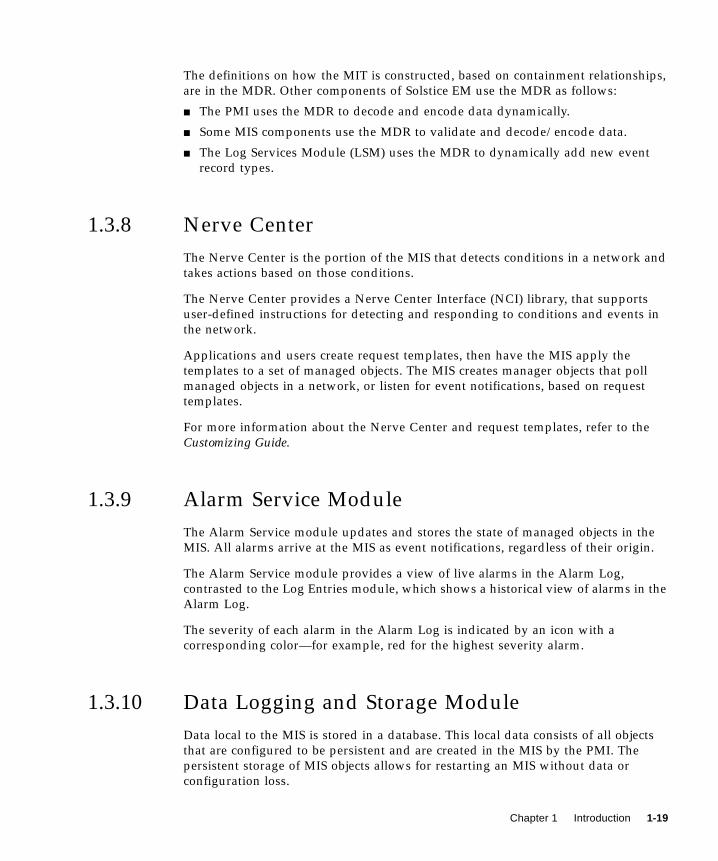
The definitions on how the MIT is constructed, based on containment relationships,
are in the MDR. Other components of Solstice EM use the MDR as follows:
■ The PMI uses the MDR to decode and encode data dynamically.
■ Some MIS components use the MDR to validate and decode/encode data.
■ The Log Services Module (LSM) uses the MDR to dynamically add new event
record types.
1.3.8 Nerve Center
The Nerve Center is the portion of the MIS that detects conditions in a network and
takes actions based on those conditions.
The Nerve Center provides a Nerve Center Interface (NCI) library, that supports
user-defined instructions for detecting and responding to conditions and events in
the network.
Applications and users create request templates, then have the MIS apply the
templates to a set of managed objects. The MIS creates manager objects that poll
managed objects in a network, or listen for event notifications, based on request
templates.
For more information about the Nerve Center and request templates, refer to the
Customizing Guide.
1.3.9 Alarm Service Module
The Alarm Service module updates and stores the state of managed objects in the
MIS. All alarms arrive at the MIS as event notifications, regardless of their origin.
The Alarm Service module provides a view of live alarms in the Alarm Log,
contrasted to the Log Entries module, which shows a historical view of alarms in the
Alarm Log.
The severity of each alarm in the Alarm Log is indicated by an icon with a
corresponding color—for example, red for the highest severity alarm.
1.3.10 Data Logging and Storage Module
Data local to the MIS is stored in a database. This local data consists of all objects
that are configured to be persistent and are created in the MIS by the PMI. The
persistent storage of MIS objects allows for restarting an MIS without data or
configuration loss.
Chapter 1 Introduction 1-19

The MIS receives, processes, and stores event notifications as log records in the
database. Using the Event Logs module, you can retrieve, update, or purge records
from the database.
1.3.11 Compilers
Compilers provide a method for you to add new managed object definitions to the
MIS. If your application refers only to object classes already known to the MIS, you
will not need the compilers.
For more information about adding new object classes, see Chapter 8.
1.3.12 Message Routing Module
The Message Routing Module (MRM) manages switching and transaction
processing. The MRM routes messages to other modules such as protocol driver
modules, management protocol adaptors, client applications, object instances, and
event management.
The MRM performs scoping, including atomic operations, on local objects. It
requests routing information from the MIT.
The MRM receives and sends messages through a low-level portable management
interface (PMI), the Object Access Module (OAM), and the Event Management
Module (EMM).
1.3.13 Object Access Module
Much of the MIS’s power comes from the ability to specify what objects can do and
how they behave. The OAM processes management requests from the MRM on a
per-request basis. The MRM provides the object framework for creating and
maintaining the MIT.
Applications and users do not need to know where managed objects are in the
network, because the OAM distinguishes between local and remote objects. If a
managed object is local to the MIS, the OAM accesses the object directly. If an object
is remotely located, then the OAM routes requests through the PMI to the agent that
contains the object.
1-20 Management Information Server (MIS) Guide • October 2001

1.3.14 UNIX Processes (Daemons)
The following table contains the names of the MIS processes (daemons) in a UNIX
environment.
TABLE 1-3 Processes in a UNIX Environment
Process Description
em_autoexd Automatically extends database tables when they get full.
em_autod Monitors creation and deletion of objects in the MIS, starts
requests for new objects and stops requests when objects are
deleted.
em_cmip Implements CMIP MPA functions; starts during product
installation.
em_datad Collects performance and accounting data.
em_eds Represents an EA or an event sink that handles Event
distribution.
em_log Implements log server MPA functions.
em_log2hist Saves logs in historical files; see Chapter 6.
em_login Listens to connection requests for password authentication.
em_mis Implements the majority of MIS functions; starts when
em_services command is run.
em_mpa_jdmk Allows users to create agents in Java.
em_mpa_snmp Implements SNMP MPA functions.
em_mpa_rpc Implements RPC MPA functions.
em_ncam Handles Nerve Center actions; starts when em_services is run.
em_nnmpa Starts the global nickname (FDN translation) server. Alarms and
Event Logs use the global nickname server.
em_ns_server Naming services.
em_purged Purges old alarms from the Alarm Log.
em_sim Simple Request Manager.
em_snmfwd Forwards SunNet Manager events to the MIS for processing.
Registers with the SNM 2.x na.event daemon, receives events as
would an SNM console. Forwards events as snmAlarmEvents and
traps as snmAlarmTraps. No data reports are forwarded.
em_snmfwd has effect only if na.event is running.
em_snmfwd starts when the em_services command is run.
Chapter 1 Introduction 1-21

em_snmp-trap Listens on port 162 for SNMP traps; is a separate process from the
MIS. Traps are converted according to a user-defined mapping to
CMIP notifications and forwarded to the MIS. This daemon can be
distributed to other hosts.
em_srm Simple Request Manager.
em_toposrv Handles operations related to topology objects.
oninit Database daemon.
TABLE 1-3 Processes in a UNIX Environment (Continued)
Process Description
1-22 Management Information Server (MIS) Guide • October 2001

CHAPTER 2
Operating MIS
This chapter provides instructions for starting, monitoring and shutting down the
Solstice Enterprise Manager (Solstice EM) MIS.
This chapter describes the following topics:
■ Section 2.1 “Starting MIS” on page 2-1
■ Section 2.2 “Monitoring the Daemon Processes” on page 2-7
■ Section 2.3 “Shutting Down MIS” on page 2-10
2.1 Starting MISMIS starts automatically when you invoke the em_services command. Upon
startup, the database server is initialized before any of the MIS daemons.
Provided a license file is installed correctly and a license is available, by default, MIS
starts automatically when your machine is rebooted. To start MIS on your own,
remove the following files:
■ /etc/rc2.d/S96mis■ /etc/rc2.d/K96mis
When you invoke the em_services -start command the appropriate
Solstice EM server daemons are started. (Refer to the Managing Your Network for a
complete description of Solstice EM daemons.) None of the applications start when
you invoke the em_services -start command.
2-1

2.1.1 After a New Installation
If you chose not to have the em_setup program automatically start MIS, you must
use the em_services -reload command (reinitializes the platform) to start MIS
after the installation. Use the procedures in Section 2.1.6 “Recreating the Database”
on page 2-4.”
Installation can also be done by using the Graphical User Interface (GUI) called
Setup.
2.1.2 Under Normal Conditions
Use the following procedure for starting or restarting MIS under normal conditions.
▼ To Start or Restart MIS
1. Login as root .
2. Type:
/opt/SUNWconn/bin/em_services -start
Note – If you installed the product in a different directory, substitute your partition
name for /opt .
2.1.3 After a System Failure
If your system has a failure, restart Solstice EM using the em_services -startcommand. The database server automatically detects the failure and attempts to
recover. During recovery, the database rolls back any uncommitted transactions.
If the database cannot recover, or your system does not restart, you must recover the
database from backups. For instructions, see Chapter 5.
If the problem with your system and database is not resolved, you may need to
repair or recreate the database. For instructions, refer to either “Reintializing the
Database” on page 3“ or “Recreating the Database” on page 4.”
2-2 Management Information Server (MIS) Guide • October 2001
2.1.4 After a System Reboot
If the system has crashed and been rebooted with the em_services -startcommand, MIS is designed to start without any data loss.
1. If MIS fails to start, type:
/opt/SUNWconn/bin/em_services -reload
Caution – The following procedure permanently removes all data from MIS,
including managed objects and discovery data. Always make backups in case you
have damage later on. Also, it is strongly recommended that you export topology
information to a file. Additionally, you may want to export request templates,
conditions, poll rates, and severities. You may, also export log data for later input.
Note – If you installed the product in a different directory, substitute your partition
name for /opt
2. Initialize the system by typing:
/opt/SUNWconn/bin/em_services -init
2.1.5 Reintializing the Database
Use the following procedure to repair a damaged or corrupted database. Also, you
may want to use the following procedure when you have made numerous changes
to the configuration, then decide you want to start over with a clean configuration
and database.
Caution – The following procedure deletes data from database tables and MPA
tables. If you have not made a backup of the data, you should do so before deleting
it. Also, it is strongly recommended that you export your topology data to a file for
later importing into the database. For instructions, see Chapter 5. Additionally, you
may want to export request templates, conditions, poll rates, and severities. You may
also want export log data to input later. For more information on using the
import/export tool, see Chapter 5.
Chapter 2 Operating MIS 2-3

▼ To Reintialize the Database
1. To delete data in database tables, type:
/opt/SUNWconn/bin/em_services -init
Note – If you installed the product in a different directory, substitute your partition
name for /opt .
This command cleans the database and restarts Solstice EM.
2. When prompted to delete all current information, type:
‘Y’ to continue, or ‘N’ to return to the shell prompt.
When you type Y, the system deletes runtime data. If you type N, the system cancels
the command and returns to the shell prompt.
3. When prompted to delete all historical information, type:
‘Y’ to continue, or ‘N’ to return to the shell prompt.
When you type Y, the system deletes all historical log tables. If you type N, only the
current information is removed. The historical information remains.
2.1.6 Recreating the Database
Use the following procedure to remove all data in your database. This procedure
completely recreates your database and recompiles the Management Information
Base (MIB) files.
For example, you may want to use this procedure after you load new object models
and want to start with a new database and configuration, such as would be available
by the more time consuming process of reinstalling Solstice EM.
Caution – The following procedure permanently removes all data from MIS,
including managed objects and discovery data. If you have not made a backup of
data, it is recommended that you do so before deleting any data. Also, it is strongly
recommended that you export topology information to a file. Additionally, you may
want to export request templates, conditions, poll rates, and severities. You may also
want export log data to input later. For more information on using the
import/export tool, see Chapter 5.
2-4 Management Information Server (MIS) Guide • October 2001

▼ To Remove all Data in Your Database
1. Start MIS, recreate the entire database, and recompile all MIBs, GDMO, andAbstract Syntax Notation One (ASN1) documents by typing:
/opt/SUNWconn/bin/em_services -reload
Note – If you installed the product in a different directory, substitute your partition
name for /opt .
A prompt asks if you want to delete all data from the database.
2. When prompted to delete all database information, type:
‘Y’ to continue, or ‘N’ to return to the shell prompt.
If you type Y, the system performs the following actions:
■ stops the database server and removes all data
■ recreates the directory and database structure
■ recompiles and reloads MIBs, GDMO, and ASN1 documents
■ recreates database tables and indexes
■ restarts Solstice EM daemons
2.1.7 Options and Commands for em_services
This section summarizes all the options and commands available for the
em_services command. The following table lists the options available for the
em_services command. You can use multiple options as required.
▼ To Invoke the Help Option
● Invoke the help option by typing:
/opt/SUNWconn/bin/em_services <command>
Note – In order to run commands from the command line, you will first need to
source the emenv.csh (emenv.sh ) file.
Chapter 2 Operating MIS 2-5

The following table lists the commands available for the em_services command.
Unlike the options for the em_services command, only one command can be
specified at a time.
The following table lists the options available for the em_services command. You
can use multiple options as required.
TABLE 2-1 Commands for the em_services
Command Description
-abort Aborts MIS daemons immediately
-help Displays the options and commands for the em_services command
-init Reinitializes the platform
-reload Creates the data repository and reinitializes the platform
-start Restarts MIS daemons in the state in which they were last shutdown
-status Displays the status of MIS daemons
-stop Stops MIS daemons
-version Displays the current version number
TABLE 2-2 Optional Parameters for the em_services Command
Parameter Description
-debug Enables debugging
-force Forces the command to work without prompting you for confirmation
-quiet Quiet suppresses all output
2-6 Management Information Server (MIS) Guide • October 2001

2.2 Monitoring the Daemon ProcessesThe Process Monitor monitors the daemon processes started by the Solstice EM
platform. If a process dies unexpectedly, the monitor will attempt to restart the
process. Some major daemons such as em_mis cannot be simply restarted, since they
are critical to the functioning of the platform. In these cases, the platform is restarted
by the monitor(em_services -start) .
Depending on their design, applications may be able to deal with the timeout period
while a process is being restarted. If not, then the applications may need to be
restarted.
The process monitor also provides a facility for escalating actions in the case of
repeated failure. If a process failure results in the platform failing, then the platform
is restarted. If the restart is unsuccessful, then a pre-defined escalation action can be
performed. Up to 4 levels of escalation are supported which are user configurable.
Note – You must logon as root to perform the actions of starting and stopping the
monitor.
2.2.1 Starting the Process Monitor
The process monitor can be started either of these ways:
■ The monitor is automatically started when you invoke em_services command
to bring up the Solstice EM platform.
Note – Choose no-monit option to start the process if you do not want to start
automatically.
■ You can start the process monitor when the Solstice EM platform is up and
running, by running em_monitor -restart , which will terminate any running
monitor and start a new one. If the Solstice EM platform is not up, then you must
bring it up by running em_services with the appropriate option.
Note – You cannot start a monitor manually while em_services startup script is
still running while the platform startup is in progress.
Chapter 2 Operating MIS 2-7
2.2.2 Stopping the Process Monitor
The process monitor can be stopped in either of these ways:
■ Is automatically stopped when the em-services -stop command is executed.
■ You can stop by running em_monitor -stop command, which will stop all the
monitoring activity. This command also cleans up and initializes the escalation
level back to 0, in case recovery fails and manual intervention is required.
2.2.3 Monitor Timeouts
When em_services start, the monitor monitors the progress of em_services . If
any daemon does not start within a specified time period, the monitor assumes that
it has failed and will initiate corrective action.
In some cases, such as reloading a platform ( with em_services -reload ), with a
large number of objects, the monitor may timeout the process, and erroneously
initiate recovery actions.
In order to avoid this situation, you can do one of the following:
■ Use the no-monit option with em_services while doing a -reload or -init. Once the Solstice EM platform is up, you can start the monitor by running
em_monitor -restart .
■ You can increase the timeout period by setting the environment variable
MONITOR_DELAY. The default value of this variable is 20, for example, by setiing
MONITOR_DELAYvariable to 40, you can double the timeout period.
Note – MONITOR_DELAYcan only be set to an integer value between 1 and 1000.
You do not need to change MONITOR_DELAYto account for system speed.
2.2.4 Configuring Escalation Actions
You can specify any action to be performed by the monitor when the platform fails.
There are four levels of escalation, 1 to 4. Level 0 is only a process restart and not
user configurable. Level 1 is the first user-configurable level, and performed when
level 0 fails. If level 1 fails, the monitor escalates to level 2, and so on, until level 4 is
reached. If level 4 is reached and the platform is still not up and running, then the
level 4 action is repeated endlessly. If the monitor is stopped at any time, then all
monitoring and escalation activity ceases.
2-8 Management Information Server (MIS) Guide • October 2001

The escalation action to be specified can be any executable Unix command or script.
You specify the action in a file in the /opt/SUNWconn/em/bin directory called
escalation_info . The format for specifying the action is:
# This is a comment
<level> <action>
<level> <action>
<level> is a number from 1 to 4, and <action> is any Unix command or
executable shell script file name. <action> must be specified on a single line, (“\”
is not allowed). Each <level> <action> pair should be on a separate line. Any
whitespace before <level> is ignored. If level is not a number from 1 through 4, the
entire line is ignored. A line beginning with a “#” is a comment line and is ignored.
There are system specified defaults for each escalation level. These are:
# System defined escalation levels
1 em_services -start
2 em_services -stop -force
3 em_services -stop -force
4 em_services -stop -force
Note – em_services -stop (or -abort ) will stop the monitor as well.
Consider this example, Supposing you want to stop the platform at level 3 and send
a message to Fred, the administrator. The file escalation_info would be written
as:
Where call_fred is a shell script:
When level 3 is reached, this would stop the platform (and all further monitoring
activity), and would execute the mail command. All the other levels would be
specified at their default levels.
CODE EXAMPLE 2-1 File escalation_info
# Level 3 escalation: Need to wake up Fred.3 call_fred
#! /bin/ksh/opt/SUNWconn/em/bin/em_services -stop -forcemail fred@home < panic_message
Chapter 2 Operating MIS 2-9

Note – Any escalation action/script should either stop the platform or attempt to
restore the platform. Otherwise, the monitor will escalate to the next level.
Caution – When specifying em_services -init or em_services -reload as
actions, remember that these actions could destroy ALL runtime data and should be
used with care.
2.3 Shutting Down MISThe two methods for shutting down MIS are normal mode and emergency mode.
The first method is the standard for most cases, providing a graceful shut down
process. The second method is for emergencies, when you need to shut down MIS
immediately to prevent data loss or corruption.
2.3.1 In Normal Mode
Use the normal mode to gracefully shut down MIS and any processes. The database
implicitly rolls back all active transactions and immediately disconnects all users.
Pending processes are placed in shutdown mode, and when conditions are
acceptable, the processes are exited.
Caution – Do not use the kill command to shut down any Solstice EM server
processes.
▼ To Shut Down MIS in Normal Mode
● Shut down MIS in normal mode by typing:
/opt/SUNWconn/bin/em_services -stop
Note – If you installed the product in a different directory, substitute your partition
name for /opt
2-10 Management Information Server (MIS) Guide • October 2001
2.3.2 Using Emergency Mode to Shut Down MIS
Use the emergency mode to immediately shut down MIS and any processes. Always
try to perform a shutdown using the normal mode method before advancing to the
emergency mode method.
Use the emergency mode for shutting down MIS when:
■ MIS is functioning irregularly and you have already tried the normal shut down
method.
■ You experience problems while starting MIS.
■ You need to terminate MIS immediately due to an emergency, such as an
impending power outage.
▼ To Shut Down MIS in Emergency Mode
● Shut down MIS in emergency mode by typing:
/opt/SUNWconn/bin/em_services -abort
Note – If you installed the product in a different directory, substitute your partition
name for /opt
Once you enter the abort command, MIS stops immediately.
Chapter 2 Operating MIS 2-11

2-12 Management Information Server (MIS) Guide • October 2001

CHAPTER 3
Accessing a Remote MIS
This chapter provides instructions for accessing a remote Management Information
Server (MIS). This chapter includes information about implementing a multiple-MIS
architecture. Communication from one MIS to another allows you to view managed
objects in a remote MIS as if they existed in your local MIS.
This chapter describes the following topics:
■ Section 3.1 “Implementing a Multiple-MIS Architecture” on page 3-1
■ Section 3.2 “Comparing MIS-to-MIS Examples” on page 3-2
■ Section 3.3 “Establishing MIS Connections” on page 3-7
■ Section 3.4 “Sharing Data Between Connected MISs” on page 3-8
■ Section 3.5 “Re-establishing a Remote MIS Link” on page 3-11
3.1 Implementing a Multiple-MISArchitectureTo manage multiple network resources and increase system availability, you may
want to distribute management information, control, and authority over multiple
MISs. In a multiple-MIS architecture, the following apply:
■ Network traffic and processing can be distributed between MISs.
■ In an environment where two or more MISs need to transfer information or act on
behalf of each other, one MIS takes on a manager role and the other can act in the
agent role. Other MISs route information through the managing MIS.
■ Users and applications access and act on consistent management information,
without regard to location.
3-1

■ All information is gathered via management requests to MIS. (There is no explicit
MIS-to-MIS interface.)
■ Any MIS can locate requested managed information and execute requests, thereby
distributing the processing load.
Using a multiple-MIS architecture is referred to as MIS-to-MIS communication. MIS-
to-MIS communication occurs when two or more MISs are connected and configured
to forward requests for managed objects while performing the tasks of agent and
manager.
MIS forwarding a request is acting in the manager role, while MIS receiving the
request is acting in the agent role. To an application, it is transparent whether the
object accessed is local or non-local.
MIS-to-MIS communication is analogous to NFS mounting a file system.
Configuring a branch of the MIT for MIS-to-MIS communication is often referred to
as mounting a section of the MIT.
In a management system such as an MIS, a service is provided to a predetermined
set of managed objects in the MIT. Because objects for which MIS provides services
are a subset of objects in the global name space, MIS must be able to act in both a
manager and agent role. The division of roles is determined by the configuration of
MIS and the requirements of the management framework. Refer to FIGURE 3-1 and
FIGURE 3-2 for examples of MIS-to-MIS configurations.
3.2 Comparing MIS-to-MIS ExamplesIf you are thinking about implementing a multiple-MIS architecture for network
management, use this section to compare examples of MIS-to-MIS communication
with your MIS and network requirements. This information may help you decide
whether to connect multiple-MISs.
3-2 Management Information Server (MIS) Guide • October 2001

3.2.1 Accessing Objects Without an MIS-to-MIS
Connection
Refer to the following figure for an example of the MIT for two MISs, called A and
B, which are not connected. You might choose a configuration of this type if Sys=A
and Sys=B must remain unknown to each other.
FIGURE 3-1 Two Unconnected MISs
If an application needs to be aware of multiple MISs, the awareness should come
from an MIS-to-MIS connection. For example, if Alarm Manager needs to display
logs from MIS A and MIS B, an MIS-to-MIS connection will enable doing that. There
are several applications in EM that are multi-MIS aware. There can be one
association between an MIS-to-MIS connection.
sys=A
A=1 A=2
AA=1 AA=2 AA=3
B=1
BB=1
Root Root
sys=B
MIS BMIS A
Chapter 3 Accessing a Remote MIS 3-3

3.2.2 Accessing Managed Objects With an MIS-to-MIS
Connection
Refer to the following figure for an example of the same two MISs from FIGURE 3-1
which are now connected, with MIS A acting in the manager role and MIS B acting
in the agent role.
FIGURE 3-2 MITs of Two Connected MISs
When an application connected to MIS A accesses any managed object with the first
RDN equal to /sys=B, such as the managed object /sys=B/B=1 /BB=1, the request is
forwarded by MIS A to MIS B.
The first Relative Distinguished Name (RDN) in the DN is used to decide if the
request is local or remote. If the object /sys=A/A=2 is accessed, MIS A acts in the
agent role and returns the local object. Actually, the Remote versus Local lookup is
based on a special Fully Distinguished Name (FDN) table stored in MIS, which
contains the FDNs of all “remote” trees.
To the application, access to the object on MIS A or MIS B is transparent. It is only
aware that it has retrieved two objects with DNs. MIS, based on the first RDN of the
requested DN, determines where the object actually resides.
It is possible for MIS B to mount MIS A so that whether the application is connected
to MIS A or MIS B, the application accesses the same objects.
sys=A
A=1 A=2
AA=1 AA=2 AA=3
Root
B=1
BB=1
Root
sys=B sys=B
MIS1 in manager role MIS2 in agent role
3-4 Management Information Server (MIS) Guide • October 2001

The example in FIGURE 3-2 presents a very simple and effective use of MIS-to-MIS
communication. This hierarchical management scheme allows you to configure
network management in an organized fashion.
In the following examples, suppose a company has a building with three physical
networks:
■ One system administrator (SA1) is responsible for the overall configuration.
■ Another system administrator (SA2) is responsible for all the networks in the
building.
■ A third system administrator (SA3) is responsible for each individual net.
Assuming that each following box represents either an MIS or a system
administrator, you can obtain the following configuration using a multiple-MIS
architecture. An arrow going from one MIS to another dictates a manager-to-agent
and agent-to-manager role. A line from a system administrator (sys=B) to an MIS
denotes a connection.
When (SA1) connects to MIS B1, the MIT displays objects from MIS B1, Net 1, Net 2,
and Net 3. Refer to the following figure for an illustration. Solid black squares
represent remote objects. In this case, MIS B1 is connected to either Net 1, Net 2, or
Net 3. The Net 1, Net 2, and Net 3 are connected to each other.
FIGURE 3-3 Local and Remote Objects as Seen from MIS Net 1
sys=B 1sys=Net 3sys=Net 2sys=Net 1
Root
Chapter 3 Accessing a Remote MIS 3-5

When SA2 connects to MIS Net 1, the Management Information Tree (MIT) displays
objects from Net 1, Net 2, and Net 3. Refer to the following figure for an illustration.
Solid black squares represent remote objects. In this case, Net 1, Net 2, and Net 3 are
connected to each other. For example, Net 1 connects to Net 2 and Net 3.
FIGURE 3-4 Local and Remote Objects as Seen From MIS Net 2
When SA3 connects to MIS Net 3, the MIT only contains objects that are local to Net
3, as illustrated in the following figure.
In this scenario, it would be possible to let SA3 see objects from Net 2 and Net 1 by
mounting Net 1 and Net 2 on Net 3. Refer to the following figure. This mount would
give SA3 the same access and view as SA2
.
FIGURE 3-5 Objects Seen From MIS Net 3
sys=Net 3sys=Net 2sys=Net 1
Root
sys=Net 3
Root
3-6 Management Information Server (MIS) Guide • October 2001

3.3 Establishing MIS ConnectionsUse MIS Connections to establish a connection between your local MIS and a remote
MIS. You can set up your system so that multiple MISs are connected continuously.
Also, you can use MIS Connections application to connect on a one-time basis to a
remote MIS.
MIS Connections is normally started from the Network Tools as described in the
following procedure.
▼ To Establish an MIS Connection
From the Network Tools Window
● Click Administration Tool ➔ MIS Connections.
From the Command Line
● Type:
em_mismgr [options]
Refer to the following table for a list of optional parameters.
TABLE 3-1 Optional Parameters for the em_mismgr Command
Option Description Default
-help Prints a list of options (with
descriptions) for the em_mismgrcommand.
-host < hostname> Specifies the <hostname> of the primary
MIS which connects to another remote
MIS.
local host
-port < port> Specifies the port number. 5555
Chapter 3 Accessing a Remote MIS 3-7

3.4 Sharing Data Between Connected MISsOnce you are connected to another MIS you have these options:
■ Use the default Event Forwarding Discriminators (EFD) to make data about all
events available to the other MIS.
■ Define a non-default EFD to make only data about selected events available to the
other MIS. (This option applies when you want to filter out event types.)
EFDs are mechanisms for disseminating event information. They are a managed
object class defined in ISO DMI (ITU X.721 ISO/IEC 10165-2). EFDs include a
discriminator construct attribute (frequently referred to as a discriminator), a
destination attribute, and optional attributes. The discriminator construct specifies a
filter that MIS uses to test event information. Event information that passes the test
is sent to each destination specified by an EFD destination attribute.
When an EFD passes event information from one MIS to another, the MIS that sends
the event acts as the agent; the MIS that receives the event acts as the manager.
-break This option works with the -remoteoption only. If you specify -break with
-remote <machine name> then the MIS
connection with that remote MIS is
removed.
-remote <remote_MIS> Specifies the remote MIS.
-discrim<discriminator>
Specifies the discriminator construct. and:{ }
TABLE 3-1 Optional Parameters for the em_mismgr Command (Continued)
Option Description Default
3-8 Management Information Server (MIS) Guide • October 2001

3.4.1 Accessing Data About All Events
To make data about all event types available to other MISs in your network, perform
the following procedure.
▼ To Access Data About All Events
1. In the Network Tools window, select Administration ➔ MIS Connections.
The MIS Connections window is displayed, as shown in the following figure.
FIGURE 3-6 MIS Connections Window
2. In the MIS Host field, type the name of the remote MIS.
3. Click Connect.
MIS Connections uses the default EFD to establish a connection with the specified
MIS. Your local and remote MISs now share information.
The default EFD consists of the definition and:{}.
Caution – This definition causes all events to be forwarded.
Chapter 3 Accessing a Remote MIS 3-9

3.4.2 Accessing Data about Selected Events
To make data about selected event types available to other MISs, perform the
following procedure.
▼ To Access Data About Selected Events
1. In the Network Tools window, select Administration ➔ MIS Connections.
2. Click Advanced.
MIS Manager displays the Advanced window, as shown in the following figure.
.
FIGURE 3-7 MIS Connections Advanced Settings Window
3. In the MIS Host field, type the name of the machine on which the remote MIS isrunning.
3-10 Management Information Server (MIS) Guide • October 2001

4. In the Discriminator field, define the Event Forwarding Discriminator (EFD).
For information on Common Management Information Service (CMIS) filtering,
refer to the Customizing Guide and Managing Your Network.
5. In the Port field, type the remote port number for the connection.
The default port number is 5555. You can type a non-default port number in this
field.
6. Click Connect.
MIS Connections uses the non-default EFD to establish a connection with the
specified MIS. Now your local and remote MIS share information.
3.5 Re-establishing a Remote MIS LinkWhenever a remote MIS link is re-established or goes down, an alarm is sent to MIS.
The alarm will indicate if the remote MIS is down, or the remote MIS is up with an
alarm/notification called connectivityChange . This will also cause an update of
the network topology in Viewer, if the Viewer is running. The Connection Manager
broadcasts a communicationsAlarm to the appropriate applications. The event(s)
are logged into the Log Manager where they will display.
Chapter 3 Accessing a Remote MIS 3-11

3-12 Management Information Server (MIS) Guide • October 2001

CHAPTER 4
Managing MIS
This chapter provides information and procedures for managing MIS. Many of the
applications and tools in Solstice Enterprise Manager (Solstice EM) are used with
MIS. For some topics in this chapter, references to related publications are provided.
These related publications provide detailed information and instructions for
performing tasks affecting MIS.
This chapter describes the following topics:
■ Section 4.1 “Setting Up MIS on Your Network” on page 4-1
■ Section 4.2 “Controlling Access” on page 4-2
■ Section 4.3 “Customizing the MIS Configuration” on page 4-2
■ Section 4.4 “Starting MPAs” on page 4-2
■ Section 4.5 “Detecting Events and Conditions” on page 4-10
■ Section 4.6 “Troubleshooting” on page 4-10
4.1 Setting Up MIS on Your NetworkAfter Solstice EM is installed, you may want to customize your installation,
especially the implementation of MIS. For detailed information, refer to the
Customizing Guide.
If your network has many resources to manage, you may want to implement a
multiple-MIS architecture. For examples and information about implementing a
multiple-MIS architecture on your network, refer to Chapter 3.
4-1
4.2 Controlling AccessUsing the Security application, you control who has access to applications, MIS, and
the database. To administer access control, refer to the Managing Your Network. This
guide provides information and instructions for performing access control
administration.
4.3 Customizing the MIS ConfigurationFor information and procedures on how to customize your MIS configuration, refer
to the Customizing Guide.
4.4 Starting MPAsDepending upon the options selected by the user who installed Solstice EM, you
may have the following MPAs installed on your system:
■ CMIP
■ RPC and SNMP
■ MPA
The installed MPAs start automatically when Solstice EM is started or restarted. If
you want to use an MPA that was not installed, refer to the Installation Guide for
installation procedures, and use the following procedures to start the applicable
MPA.
4.4.1 Starting CMIP
To use the Common Management Information Protocol (CMIP), install the CMIP
MPA package (SUNWemcpa) and start the CMIP MPA daemon (em_cmip ) as root by
running the following command:
/etc/rc2.d/S98cmipmpa start
4-2 Management Information Server (MIS) Guide • October 2001
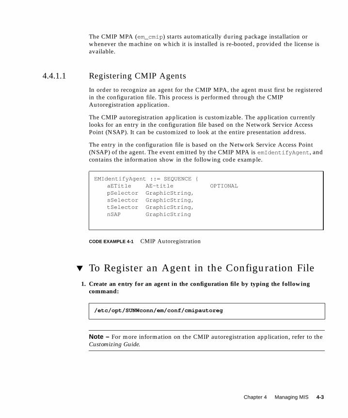
The CMIP MPA (em_cmip ) starts automatically during package installation or
whenever the machine on which it is installed is re-booted, provided the license is
available.
4.4.1.1 Registering CMIP Agents
In order to recognize an agent for the CMIP MPA, the agent must first be registered
in the configuration file. This process is performed through the CMIP
Autoregistration application.
The CMIP autoregistration application is customizable. The application currently
looks for an entry in the configuration file based on the Network Service Access
Point (NSAP). It can be customized to look at the entire presentation address.
The entry in the configuration file is based on the Network Service Access Point
(NSAP) of the agent. The event emitted by the CMIP MPA is emIdentifyAgent , and
contains the information show in the following code example.
CODE EXAMPLE 4-1 CMIP Autoregistration
▼ To Register an Agent in the Configuration File
1. Create an entry for an agent in the configuration file by typing the followingcommand:
Note – For more information on the CMIP autoregistration application, refer to the
Customizing Guide.
EMIdentifyAgent ::= SEQUENCE {aETitle AE-title OPTIONALpSelector GraphicString,sSelector GraphicString,tSelector GraphicString,nSAP GraphicString
/etc/opt/SUNWconn/em/conf/cmipautoreg
Chapter 4 Managing MIS 4-3

2. Start the CMIP Autoregistration application by typing the following command:
4.4.1.2 Configuring
▼ To Configure a toponode
1. To configure a toponode as a CMIP agent, use one of the following methods.
The Object Properties window will display.
■ In the Network Tools window select Viewer and then add a device to the
Network Views using the default procedure in the Object Properties (using only
the hostname).
■ From the command line interface use one of the following commands:
■ em_oct -name <topo-node-name>
■ em_oct -id < topo-node-id-number>(the toponode Id is shown on the Network Views status bar if you double-
click the Network Views icon for that toponode)
2. Select Agent.
3. Select CMIP.
When an agent establishes an association with the CMIP MPA, the CMIP MPA sends
an event to the CMIP Autoregistration application. The event contains addressing
information for that agent. Based on the event information, the CMIP
Autoregistration application looks for the corresponding entry in the configuration
file. If it finds the entry, it creates an entry for the agent in the CMIP table.
4. Click Add in the Agent subwindow.
The CMIP agent version of em_oct will display.
$(EM_HOME)/bin/em_cmipautoreg
4-4 Management Information Server (MIS) Guide • October 2001

5. Fill in the CMIP agent entry with the appropriate information according to thefield description in following table.
TABLE 4-1 Field Description for CMIP
Entity Name Specify the name of the remote agent with which you want to
communicate. The value can be a string, Object Identifier (OID), or
Distinguished Name (DN). Click the down arrow to see a list of
known agents. To delete an agent, click Delete, select an agent from
the resulting list, then click OK. After specifying an agent, all the
other fields in this window for which information exists in the agent
are filled.
Agents DNs This field displays the list of DN objects that the agent manages.
When configuring a CMIP agent for a particular topology node, you
must select an Agent DN (from the list) by which that topology
node is managed.
MO DN Specify the DN (top-most node) of the MIT to be managed by the
remote agent. For example, if the remote agent is located on a
machine called poignant , type /systemId=name:”poignant” in
the MO DN field and click Add.
/systemId=name:”poignant” will display in the Agents DNs
field.
To delete a DN, select the one you want to delete and click Delete.
MPA Addresses Select the Default toggle button to apply the default values for the
MPA Host and MPA Port. The default host is <localhost>, and the
default port number is 5557. To customize these values, select the
Custom toggle button and type the MPA host and port number.
Presentation Address You must type the appropriate Presentation Selector, Session
Selector, Transport Selector, and Network SAP for the agent you are
configuring.
Click Apply to create the object, or click OK to create the object and
dismiss the CMIP Configuration window.
Sample Presentation Address values when using CLNS(LLC1)
/CONS(X.25)
Presentation Selector: 4444
Session Selector: 3333
Transport Selector: 3007
Network SAP: 4700040006000108002011e7f001
Sample Presentation Address values when using TCP-IP (RFC1006)
Presentation Selector: dflt
Session Selector: Prs
Transport Selector:CMIP
Network SAP: 81924b94
Chapter 4 Managing MIS 4-5
Note – The Network SAP in this case is the value of the IP address of the CMIP
Agent represented in hexadecimal.
6. Click Apply.
7. Click OK.
The Object Properties window displays again.
8. Click Apply.
9. Click OK.
Note – You can verify that the Agent is properly added to the toponode by clicking
the toponode in Network Views.
4.4.2 Starting RPC and SNMP
The Remote Procedure Call (RPC) and SNMP MPAs start automatically during
package installation or whenever the machine on which they are installed is re-
booted, provided the license is available.
▼ To Start RPC and SNMP Independently
● If you want to start RPC and SNMP independently, start the MPA daemon asroot by running the following command:
4.4.3 Starting MPAs on a Remote Machine
To prepare the system for starting an MPA on a remote machine, the remote machine
must have the MPA package installed.
/etc/rc2.d/S98ipmpa start
4-6 Management Information Server (MIS) Guide • October 2001

▼ To Setup and Start a Remote MPA
1. Make sure the MPA packages are installed on the remote machine (SUNWemipaSNMP and RPC, and/or SUNWemcpafor CMIP).
Both of these packages depend on the Solstice Enterprise Manager Common
Libraries, so the SUNWemalbpackage must also be installed on the remote machine.
Additionally, the CMIP MPA requires a license file. Set the LM_LICENSE_VARIABLEenvironment variable on the remote machine so that it points to the license file (for
example, license.dat ), which in turn points to the machine where the license
server is installed (usually, the same machine as MIS).
2. In the Network Tools window select Administration ➔ Security.
Note – This step needs to be done on the primary machine or the machine where
the MIS process is running.
▼ To Start an MPA on a Remote Machine
Note – This must be done on the machine where the MIS process is running.
1. In the Network Tools window, select Administration ➔ Security as illustrated inthe FIGURE 4-1
FIGURE 4-1 Security Window
Chapter 4 Managing MIS 4-7

2. Select Actions ➔ Security Defaults to display the Security Defaults window, asillustrated in the following figure.
If Security is set to Off, the message “EM Security is currently disabled in the MIS”
is displayed. You can turn Access Control back on from the Defaults window.
FIGURE 4-2 Security Defaults Window
3. Use the Security Off/On toggle switch to set the security function.
4. Under Security Defaults set the following defaults to either Deny with response,Deny without response, Abort association, or Allow:
■ Action
■ Create
■ Delete
■ Get
■ Set
■ Filter
4-8 Management Information Server (MIS) Guide • October 2001

■ Multiple Object Selection
■ Events
And set Events to either Allow or Deny.
5. Set Security Logging and Audit Logging to Off, Summary, or Detailed.
6. Type the Trusted Host name in the text field.
The Trusted Host is the remote machine that has MPA installed. When superusers
connect from a remote machine, for full access to be granted the remote host must be
defined as a Trusted Host.
7. Click Add.
8. Click OK.
9. Login as root on the remote machine and start the MPA by typing the followingcommand:
The <mpa variable> represents the name of the MPA you want to start. Specify
cmipmpa to start the CMIP MPA, or ipmpa to start the IP MPA.
Note – You must start the MIS process before you start the MPAs.
4.4.4 Stopping MPAs
You can stop the MPAs by typing the following command:
/etc/rc2.d/S98 <mpa variable> stop
where the <mpa variable> is either cmipmpa or ipmpa.
/etc/rc2.d/S98 <mpa variable> start
/etc/rc2.d/S98 <mpa variable> stop
Chapter 4 Managing MIS 4-9
4.4.5 Using em_topo_args for Third Party Integration
The command em_topo_args is used to pass arguments to applications that are
launched from the Object Menu of a device. Refer to the following example.
In this example, serviceProvider is an attribute added to the
topoNodeUserData of a device type and so em_topo_args can be used to extract
its value.
The em_topo_args command was written for backwards compatibility, although it
can be used for non-backward compatible applications. The % is from SNM. % in
SNM is how you pass an element type (glyph) schema attribute to the command
line.
There are also some limitations on what you can pass on to an application. If the
topoNodeUserData type is a SET OF xxx, it will not work since topoargs does
not have a way to pull out individual members of a SET. It does work for SEQ.
4.5 Detecting Events and ConditionsFor information about detecting events and conditions in your network, refer to the
C++ API Reference.
4.6 TroubleshootingIf you encounter messages or unusual behavior with MIS, refer to the CustomizingGuide. This guide contains helpful information for determining the cause and
resolution of MIS issues.
One of the most common errors occurs when you or another user makes changes
that require restarting Solstice EM, and you or the other user do not restart the
system. For example, when adding shared memory and semaphores, you have the
option of automatically or manually rebooting the system. If you choose the manual
option, then later forget to reboot, you’ll see a database error when you attempt to
start MIS.
$EM_HOME/bin/em_topo_args EM_UNIQUE_ID “/bin/echo%serviceProvider > /tmp/test2”
4-10 Management Information Server (MIS) Guide • October 2001

A simple way to check is to look for the /reconfigure and /tmp/reboot files in
the directory where Solstice Enterprise Manager was installed. (Use the command
ls -l at the appropriate directory level). If either file exists, then the host must be
rebooted.
Chapter 4 Managing MIS 4-11

4-12 Management Information Server (MIS) Guide • October 2001

CHAPTER 5
Backing Up/Restoring andExporting/Importing Data
This chapter explains the procedures for protecting your data through backing up
and restoring.
This chapter describes the following topics:
■ Section 5.1 “Guidelines for Backing up and Restoring Data” on page 5-1
■ Section 5.2 “Guidelines for Importing and Exporting Data” on page 5-8
■ Section 5.3 “Exporting Network View Data” on page 5-10
■ Section 5.4 “Converting Legacy Data” on page 5-12
5.1 Guidelines for Backing up and RestoringDataTo protect your system from serious data loss, periodically back up both the
database and network views data. There are two ways to do this:
■ Solstice Backup and Restore
■ Solstice Enterprise Manager (Solstice EM) preparation procedures and your own
backup utility (you can backup data online)
5-1

5.1.1 Testing Your Backups
Corrupt data can be transferred from source to destination and can go undetected
until you restore the data and try to recover the database. To minimize this problem,
test your database backups. Examples of test procedures are included in this section.
A suggested schedule is to test backups at least every three months.
5.1.2 Preparing for Backup
The Database Backup/Restore Tool allows you to specify a file to which you can
backup database information. Similarly, you can specify a file from which you can
restore database information. The database must be up to do a backup. Similarly, the
database must be down to restore it.
Use the Database Backup/Restore Tool to prepare for backups. During a backup,
users can continue to make entries into the database. The entries are queued and
then processed after the backup is completed. The Database Backup/Restore Tool
can be brought up from either the Network Tools window or the command line.
▼ To Perform a Backup
1. Type the following command:
em [-host <hostname>] &
2. Prepare for online backup by clicking Administration.
Note – The database must be up in order to do a backup.
3. On the Administration window, click Database Backup/Restore.
The Database Backup/Restore window displayed is shown in the following figure.
Any data typed at this point is queued until the backup is complete.
FIGURE 5-1 Backup and Restore Window
5-2 Management Information Server (MIS) Guide • October 2001

4. In the File field, specify a file name where the data will be backed up.
5. Click Backup.
Back Up from the Command Line
● Type the following command:
em_dbarchive
Restore from the Command Line
● Type the following command:
em_dbrestore
5.1.3 Backing up and Restoring Network Views Data
and Agents
Network views data are nodes created by users to logically model managed objects
(network resources). These nodes point to network resources, which you can see
graphically displayed in the Network Views. For instructions on how to view
network view nodes and their attributes, refer to the Managing Your Network.
Agents are associated with network view nodes. These agents are most commonly
CMIP, RPC, and SNMP.
If network views data were lost or corrupted, you would have to recreate all nodes
and their hierarchy. For larger networks, this task is a significant effort.
You may want to use the following guidelines for doing backups:
■ Whenever changes are made (for example, daily, or weekly)
■ Before changing the configuration of MIS or Solstice EM
■ Before recreating or rebuilding the database
After backup, you can find your backup files in the directory you specified. In order
to change this default location, go to the current path and change the filename.
These files must be left accessible to the Solstice EM user.
If your system crashes, MIS is designed to restore to normal condition when the
system is rebooted. However, there may be times when you need to restore MIS
manually. For example, if the database is damaged, a default installation is
performed, or data has been removed and MIS does not restore itself. Under these
conditions, you will need to use your latest backup files to restore the database.
Chapter 5 Backing Up/Restoring and Exporting/Importing Data 5-3

5.1.4 Supporting Migration Paths
The migration path from Solstice EM 2.0 and 3.0 is supported in this version of the
product. Also, you can import network views and agent data from one MIS to
another MIS for data redundancy. Migration is supported for data that was imported
in Solstice EM 2.1 using PMI tools. Database related tools cannot be used for
migration.
▼ To Restore the Database From the Network Tools
Window
1. Prepare for online restore by clicking Administration on the Network Toolswindow.
Note – The database should be down in order to restore it. Run em_services -stop to halt it.
2. Click Database Backup/Restore.
Any data typed at this point is queued until the data restoration is complete.
3. In the text field, specify a filename where the data will be restored.
From the Command Line
Before restoring, make sure the backup file is located in the directory you specify. To
restore a database, do the following:
1. Type the following command:
/opt/SUNWconn/bin/em_dbrestore -file <filename>
Note – If you installed the product in a different directory, substitute your partition
name for /opt .
2. To implement the restore, type the following command:
em_services -start
5-4 Management Information Server (MIS) Guide • October 2001

5.1.5 Copying Network Views and Agent Data
If your network views and agent data are damaged, or you want to copy network
views and agent data from one MIS to another, you can do this from either the
Network Tools or the command line.
Note – Make sure the target MIS is not processing other transactions and requests.
The import operation does not correct inconsistencies that may occur due to ongoing
MIS activity during the import.
▼ To Copy Network Views and Agent Data
1. On the Network Tools window, click Administration ➔ Network ViewImport/Export.
2. Enter the name of the file to which your network view objects will be imported.
Optionally, you can type a container name and a parent name.
3. Click the Object menu.
4. Select Import.
From the Command Line
1. Start the Topology Export/Import Tool from the command line by typing thefollowing command:
em_topoimex -file <filename> -import [options]
Chapter 5 Backing Up/Restoring and Exporting/Importing Data 5-5

2. In place of the filename variable, type the following command:
To import all network view-related information from a file called topo_db_info .
Refer to the following table.
3. When prompted, type your password.
When the export is complete, the system prompt returns,
4. type ls <filename>.
em_topoimex -file topo_db_info -import
TABLE 5-1 Commands for Exporting Data
Option Description
-file <filename> Specify the name of file to export to or import
from.
-clear Clears network views and agents from MIS.
-export Exports network views from the MIS. -file <filename>option is required when using this option.
-container<container>
Exports a container. Must be used in conjunction with export.
-debug Turns on debugging messages.
-help Prints a list of options (with descriptions) for the <em_topoimex>command.
-host < host> Specifies a remote MIS server.
-import Imports network views to the MIS. -file <filename> option is
required when using this option.
-parent < viewname>
Imports a previously exported container under <view name>. Must
be used in conjunction with -import.
-remote < MISserver>
Specifies a remote MIS to clear, export, or import.
-quiet Specifies quiet mode. No question asked for -clear and
-import options.
CODE EXAMPLE 5-1 Sample Export File
# MIS=”yeahright”### Exported data for topoTypeCREATE{
5-6 Management Information Server (MIS) Guide • October 2001

OC=topoTypeOI='topoTypeDBId=NULL/topoTypeId=”Device”'topoTypeAllBaseOf='{ “Interface”, “OMC”, “BTS”, “Hub”, “Router”, “Printer”, “VLR”, “Host”, “Pc”, “Sunws”, “HLR”, “BSC”, “Server”, “XCDR”, “Bridge”}'topoTypeAllDerivedFrom='{}'topoTypeAllLegalArcs='{ “Link”, “LinkContainer”}'topoTypeAllLegalChildren='{}'topoTypeBaseOf='{ “Router”, “Bridge”, “Hub”, “Host”, “XCDR”, “BTS”, “BSC”, “OMC”, “VLR”, “HLR”, “Interface”,
CODE EXAMPLE 5-1 Sample Export File (Continued)
# MIS=”yeahright”
Chapter 5 Backing Up/Restoring and Exporting/Importing Data 5-7

5.1.6 Using Solstice Backup and Restore
Another way to backup and restore data is to use the Solstice Backup product. This
is a standalone product that can be used to backup all types of data. The Solstice
product not only has backup and restore capabilities, but it allows you to specify the
following:
■ Incremental backup and restore
■ Point restore
Solstice™ Backup™ Solaris Data Backup Utility, Solstice Backup, and Solstice Backup
Turbo software form a product family that delivers heterogeneous data protection
available for enterprise computing environments. This enterprise-wide backup and
recovery solution supports virtually every network operating system, desktop
operating system, and storage device on the market. Solstice Backup provides
consistent, reliable data protection, reduces the costs of administration and
minimizes backup time.
▼ To use the Solstice Backup Configuration Utility
1. Indicate the various client system types running in the network.
2. Use the scroll bar to choose the total number of clients in the network.
3. Check any desired application options.
The “SunSoft part nos.” window indicates the products which are necessary to
protect your storage management environment.
5.2 Guidelines for Importing and ExportingDataTo back up all or part of your network views data for your MIS, use the Network
Views Import/Export. Using this tool, you export Sun’s data to an ASCII formatted
file. Later, if you need to restore network views data, you import the latest backup
(export) file.
When exporting the entire network views database, you can use a “container
export” feature. This feature exports the network view nodes within and beneath the
container in the view hierarchy. With the network view nodes, all the associated
agent objects and FDN tables are also exported.
5-8 Management Information Server (MIS) Guide • October 2001
Later when you import a file of network views data that was exported using the
container feature, you assign a “parent” node for the container that you want to
import.
You’ll need Solstice Backup J.1 and Solstice Backup Database Module for InformixTM 1.0.
5.2.1 What is Exported?
The attributes within specified object types are exported. This data includes all
objects within the following branches of MIS:
■ topoTypeDB —all topoTypeNodes
■ topoNodeDB —topoNodes (Each topoNode is identified within the export data
by its topoNodeId.)
■ topoViewDB —all topoNodes (This data must be associated with its
corresponding topoNode within the export data.)
■ topoViewNodeDB —all topoViewNodes (This data must be correctly associated
with its parent topoView and with its corresponding topoNode .)
■ internetClassId —SNMP agent objects (This object must be associated with
each topoNode object that references it.)
■ agentTableType=”RPC” —RPC agent objects (This object must be associated with
each corresponding topoNode object.)
■ agentTableType=”CMIP” —CMIP agent objects (This object must be associated
with each topoNode object that references it.)
■ subsystemId=”EM-MIS” —FDN table
5.2.2 What is Not Exported?
The following information is not exported:
■ Request data—emApplicationType=”Collection” and
emApplicationType=”NerveCenter”
■ Log data
■ User-defined managed objects
Chapter 5 Backing Up/Restoring and Exporting/Importing Data 5-9

5.3 Exporting Network View DataWhen you back up network view data, it is placed in an ASCII file. The exported
MIS information will:
■ be editable so that scripts can generate it.
■ be interchangeable between different hardware platforms.
Note – Make sure the target MIS is not processing other transactions and requests.
The export operation does not correct inconsistencies that may occur due to ongoing
MIS activity during the export.
▼ To Export Network View Data
1. Click Administration ➔ Network View Import/Export.
2. Enter the name of the file where your network view objects will be exported.
Refer to the following figure. You may also use the browse button to navigate to a
specific directory or file. Optionally, you can type a container name and a parent
name.
3. Click Object ➔ Export.
FIGURE 5-2 Network View Import and Export Window
5-10 Management Information Server (MIS) Guide • October 2001

From the Command Line
You can start Network View Import/Export by typing the following command:
1. In place of the filename variable, type the name of the file where you want toexport data.
If you are not in the target directory, remember to type the full path name. For
example, to export all network view-related information in MIS to a file called
topo_db_info , use the following command:
The following table lists the optional parameters for exporting data.
2. When you are prompted, type your <login ID> and <password>.
Your access to the Network View Export/Import functions depends on the
permissions granted to you.
3. When the export is complete, the system prompt returns. To ensure the file towhich you exported has been created, type ls <filename>.
If more than one network view database exists (due to MIS-MIS communication),
then the export operation provides the following options:
■ Export network views branches from an MIS that can be reached from the local
MIS.
■ Export a container within a network views branch from a specified MIS. (All
objects under that node are exported.)
In situations where a non-unique topoNodeName container object is specified, the
export tool prompts you to select the proper one.
5.3.1 Exporting and Importing Log Records
The em_imex command can be used to import or export log objects from or to an
ASCII file. This command is invoked from the Event Logs application by selecting
either:
■ File ➔ Import File
■ File ➔ Export to File from the Event Logs menu bar
■ Invoke the em_imex by typing em_imex [options] &
em_topoimex -file <filename> -export [options]
em_topoimex -file topo_db_info -export
Chapter 5 Backing Up/Restoring and Exporting/Importing Data 5-11

The optional parameters for the em_imex command are described in the following
table.
5.4 Converting Legacy DataTo convert legacy data, refer to the Installation Guide.
In addition to converting data from a previous version of Solstice EM, you may want
to convert network views data and agent objects to the new MIS.
TABLE 5-2 Command Line Options for em_imex
Option Description
-type<log|em_topoimex>
Type of operation.
-host server Specify the <server> of a remote MIS.
-c Specify “-c” when using the “-import” option to include the
“object creation” events for the corresponding objectCreationevents found in the log.
-e < moi> or export<moi>
Specify the managed object to export.
-f < filename> Specify the name of the file to read or create.
-i or -import Import operation (by default).
5-12 Management Information Server (MIS) Guide • October 2001

CHAPTER 6
Managing Event Logs
This chapter describes the Sun Enterprise Manager (Solstice EM) logging services.
This chapter describes the following topics:
■ Section 6.1 “Logging Event Files” on page 6-1
■ Section 6.2 “Using Event Logging” on page 6-2
■ Section 6.3 “Creating and Instantiating Logs” on page 6-5
■ Section 6.4 “Creating and Defining Events to be Logged” on page 6-6
■ Section 6.5 “Logging Received Events” on page 6-9
■ Section 6.6 “Logging Historical Records” on page 6-9
■ Section 6.7 “Merging Log Records from Different Databases” on page 6-26
6.1 Logging Event FilesThe MIS support system Management Log control functions specified in CCITT Rec.
X.735 | ISO/IEC 10164-6.
Solstice EM’s log management involves three main activities:
■ MIS logging—MIS receives, processes, and stores events as log records in the
MIT. These log records can be retrieved, updated, or purged by the Alarms via
PMI.
■ Historical logging—MIS historical log files store all the event log records
generated during MIS event processing and logging.
■ Historical Relational Database (RDB) logging—historical log files are mapped
and translated into a relational database. The Log Management activities are
illustrated in the following figure.
6-1

FIGURE 6-1 Event Log Management Activities
6.2 Using Event LoggingUsing the Event Logs, a log object can be created to capture specific MIS events. The
discriminator construct of the log object specifies the type of event that is captured.
Captured events become log records. Log records can be automatically reviewed and
manipulated using the Alarm Manager or by the Manager affiliations.
6.2.1 Logging Services
Solstice EM provides logging services that allow applications to define log objects in
the OmniPoint 1 log format, to specify the kinds of events to be logged, and to
manipulate log records.
MIS
PMI
RDBMS
API
HistoricalLogs
em_log
EDS
PMI
em_alarmmgr
6-2 Management Information Server (MIS) Guide • October 2001

Each log object contains attributes that distinguish it from other log objects. These
attributes are described in the following table.
Log objects can be created, modified, or deleted, just like any other managed objects,
through the PMI. For users, the Event Logs application offers the same functions
available through the PMI.
TABLE 6-1 Log Object Attributes
Attribute Name Description
logIdentifier Each log object is identified by its Fully Distinguished Name
(FDN) in the MIS’s MIT.
discriminatorConstruct A test that decides whether to log an arriving notification
(test can be modified).
maxLogSize Each log object has a maximum size and an attribute that
indicates when its maximum size has been reached. A
maximum size set to zero indicates no limit. Size is
expressed in octets (size can be modified).
currentLogSize Number of octets the log object and its records that now
occupy in MIS (reportable, but not an attribute that can be
modified).
nameBinding Specifies position of log object in the MIS’s MIT, beneath the
/system/log branch (reportable, but not an attribute that
can be modified).
objectClass This class is nearly always log (reportable, but not an
attribute that can be modified).
numberOfRecords The number of log records currently written in the log object
(reportable, but not an attribute that can be modified).
logFullAction(wrap/halt)
When the log is full, it either stops accepting new records or
starts to overwrite the oldest records, according to the value
of this attribute (can be modified).
administrativeState(locked/unlocked)
If locked, no events will be recorded as log records. When
set to locked, the log object cannot be written to. When set to
unlocked, allows the log object to be written to (can be
modified).
operationalState(enabled/disabled)
When set to enabled, the log object is “up.” When set to
disabled, the log object is “down” (reportable, but not an
attribute that can be modified).
Chapter 6 Managing Event Logs 6-3

Log records are added to the log object when all of the following conditions are met:
■ The notification passed the test of the discriminator construct for the log object.
■ The maxLogSize has not been reached. You can choose to have the Event Logs
either wrap around to the beginning of the file and overwrite existing log records,
or halt, in which case no new records are created.
Note – For more information on configuring these options, refer to the CustomizingGuide.
■ The administrativeState is unlocked.
■ The operationalState is enabled.
Log records are created when an event notification is logged in a log object. You can
modify the contents of a log record through the Alarms tool. Some notifications are
Alarms, that are translated to Alarm records. Alarm records are sub-classes of log
records. Only Alarm records can be viewed using Alarm Manager. Log Manager can
show all kinds of log records, including alarm records. For more information refer to
the Customizing Guide.
Log records can be deleted by the Alarms and the Log Entries. Log records are
deleted automatically as a consequence of the log full action. If the log full action is
“wrap”, an individual log record will be deleted from the beginning of a log object
when a new record is added.
Caution – Log records that are dropped or deleted due to the log full action cannot
be retrieved through the PMI since they no longer exist in the MIS.
6.2.2 Non-Default Location of Logs
The log object can reside under any containment hierarchy in the MIT, provided
there is a GDMO and ASN.1 definition for the log object. Currently, only OBED can
access logs in non-default locations.
Note – In the current implementation, the containment hierarchy specified in the
M.3100 standard has been tested. The GDMO and ASN.1 metadata for logs
conforming to this standard are the itu3100.gdmo and itu3100.asn1 documents.
6-4 Management Information Server (MIS) Guide • October 2001

6.3 Creating and Instantiating LogsTo create logs under containment hierarchies other than the default ones, and to
instantiate these logs in the system, do the following:
1. Go to em/bin directory.
2. Instantiate the M.3100 module and its definitions.
Instantiating the M.3100 module in this way is a short cut and is done because the
network-root name binding is in the vo14.gdmo document and not in the itu31000
document. The vo14.gdmo document has other dependencies and does not compile
using em_compose_all .
It is easier to load this name-binding without searching for all the dependencies of
the vo14.gdmo decanting by doing the following:
▼ To Create a Log Under managedElement(M-CREATE)
1. Create a network object instance.
2. Create a managedElement instance.
3. Create a log under managedElement type
/networkId= “..”/managedElementID=”..”/logID=pString:”..”
or/networkID=”..”/managedElementID=”..”/logID=number: N”
> cd /opt/SUNWconn/em/bin
> em_compose_all /opt/SUNWconn/em/etc/gdmo/itu3100.gdmo
> em_load_name_bindings network-root
Chapter 6 Managing Event Logs 6-5
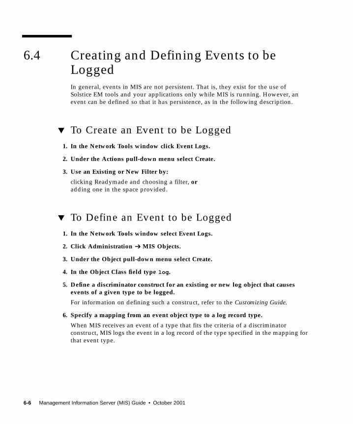
6.4 Creating and Defining Events to beLoggedIn general, events in MIS are not persistent. That is, they exist for the use of
Solstice EM tools and your applications only while MIS is running. However, an
event can be defined so that it has persistence, as in the following description.
▼ To Create an Event to be Logged
1. In the Network Tools window click Event Logs.
2. Under the Actions pull-down menu select Create.
3. Use an Existing or New Filter by:
clicking Readymade and choosing a filter, oradding one in the space provided.
▼ To Define an Event to be Logged
1. In the Network Tools window select Event Logs.
2. Click Administration ➔ MIS Objects.
3. Under the Object pull-down menu select Create.
4. In the Object Class field type log .
5. Define a discriminator construct for an existing or new log object that causesevents of a given type to be logged.
For information on defining such a construct, refer to the Customizing Guide.
6. Specify a mapping from an event object type to a log record type.
When MIS receives an event of a type that fits the criteria of a discriminator
construct, MIS logs the event in a log record of the type specified in the mapping for
that event type.
6-6 Management Information Server (MIS) Guide • October 2001

▼ To View the Mapping Between a Log Record and
its Event
1. In the MIS Objects window click EM-MIS.
2. Double-click Events Object Class.
For more information and examples on defining events for persistence, refer to the
Customizing Guide.
Alarms are a particular type of event indicating an abnormal condition. By default,
Solstice EM logs all alarms (called “AlarmLog”), which means that the default
discriminator construct accepts alarm events such as:
■ logged (which would be true for any event type that fits the criteria of an Event
Logs discriminator construct and has a mapping to a log record type)
■ have attributes that allow them to be acknowledged and cleared
■ are recognized by and displayed in Alarm Manager
The default alarm types supported by Solstice EM and the log record types to which
they are mapped are listed in the following table.
TABLE 6-2 Default Alarm Types and Log Record Types
Notification Type Log Record Type
attributeValueChange attributeValueChangeRecord
coldstartTrap eminternalAlarmRecord
communicationsAlarm emAlarmRecord
environmentalAlarm emAlarmRecord
equipmentAlarm emAlarmRecord
integrityViolation securityAlarmReportRecord
objectCreation objectCreationRecord
objectDeletion objectDeletionRecord
operationalViolation securityAlarmReportRecord
physicalViolation securityAlarmReportRecord
processingErrorAlarm emAlarmRecord
qualityofServiceAlarm emAlarmRecord
relationshipChange relationshipChangeRecord
securityServiceorMechanismViolation
securityAlarmReportRecord
Chapter 6 Managing Event Logs 6-7

The mapping shown above is defined in the file init_platform , and stored by
default in $EM_HOME/install/em_platform . The mappings are implemented by
the object event2ObjectClass , whose LDN is subsystemId=”EM-MIS”/listname=”event2ObjectClass” . Solstice EM allows you to define new events
to be mapped on new log records.
▼ To Create a New Type of Alarm Record
1. Derive a new alarm record from emAlarm Record.
2. Create a mapping in evr2oC between the events to be logged in and this new logrecord.
Note – All alarm log records, including emInternetAlarmRecord and
nerveCenterAlarmRecord , are derived from emAlarmRecord .
Together, the standard log object and Solstice EM-specific log object types have a rich
functionality that will accommodate most alarm-logging needs. To establish a
mapping at runtime, use MIS Objects application to edit evr2oclist or the
init_platform file, then restart MIS.
serviceReport securityAuditTrailRecord
snmAlarmEvent emAlarmRecord
snmAlarmTrap emAlarmRecord
snmAlarmError emAlarmRecord
stateChange stateChangeRecord
timeDomainViolation securityAlarmReportRecord
internetAlarm emInternetAlarmRecord
nerveCenterAlarm nerveCenterAlarmRecord
TABLE 6-2 Default Alarm Types and Log Record Types (Continued)
Notification Type Log Record Type
6-8 Management Information Server (MIS) Guide • October 2001
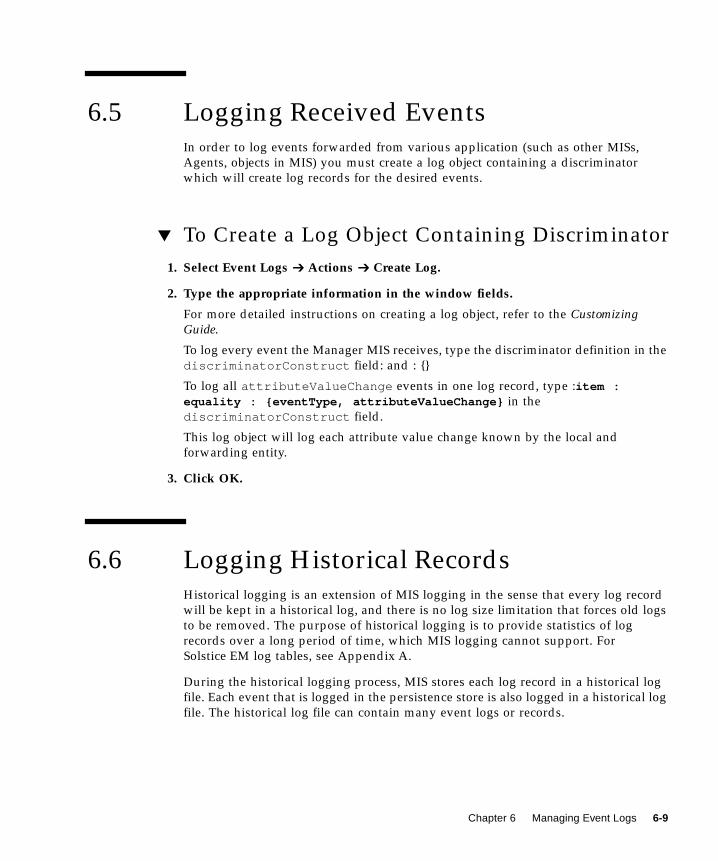
6.5 Logging Received EventsIn order to log events forwarded from various application (such as other MISs,
Agents, objects in MIS) you must create a log object containing a discriminator
which will create log records for the desired events.
▼ To Create a Log Object Containing Discriminator
1. Select Event Logs ➔ Actions ➔ Create Log.
2. Type the appropriate information in the window fields.
For more detailed instructions on creating a log object, refer to the CustomizingGuide.
To log every event the Manager MIS receives, type the discriminator definition in the
discriminatorConstruct field: and : {}
To log all attributeValueChange events in one log record, type :item :equality : {eventType, attributeValueChange} in the
discriminatorConstruct field.
This log object will log each attribute value change known by the local and
forwarding entity.
3. Click OK.
6.6 Logging Historical RecordsHistorical logging is an extension of MIS logging in the sense that every log record
will be kept in a historical log, and there is no log size limitation that forces old logs
to be removed. The purpose of historical logging is to provide statistics of log
records over a long period of time, which MIS logging cannot support. For
Solstice EM log tables, see Appendix A.
During the historical logging process, MIS stores each log record in a historical log
file. Each event that is logged in the persistence store is also logged in a historical log
file. The historical log file can contain many event logs or records.
Chapter 6 Managing Event Logs 6-9

6.6.1 Enabling Historical Logging
The environmental variable <EM_HLOG_INTERVAL> defines the rate (in hours) that
the historical log files are created in EM_HLOG_DIR(default is /var/opt/SUNWconn/em/data/HLOG ). If the value of <EM_HLOG_INTERVAL> is 0 (default),
then the historical log files are not created. You must set <EM_HLOG_INTERVAL> to
a positive value by typing the following series of commands:
em_services -stopsetenv EM_HLOG_INTERVAL <number_of_hours>em_services -start
Specify a positive integer in place of <number_of_hours> in the command shown
above. A new HLOGfile is created after every <number_of_hours> hour.
6.6.2 Logging Historical Log Files
Historical log files contain many event log records. Each logical event log record
contains information that describes the event. Logical event log records are
separated by a blank line.
Unless specified otherwise, historical log files are located in the directory specified
by the EM_HLOG_DIR environment variable (the default is /var/opt/SUNWconn/em/data/HLOG .). Type the naming convention for historical log files using the
configuration logID.yymmddhh.
Different types of log record events (for example, alarmRecord and
objectCreationRecord ) have a set of common attributes. These attributes are
derived from the eventLog . Each log record contains a description that includes the
type of event, where the event occurred, etc., and can be many lines in length. Each
description field is separated by the delimiter “:”. The optional fields appear at the
end of the record, or as attribute value pairs.
The following code example illustrates one description of a log record and
CODE EXAMPLE 6-2 provides an example of a log record specific for alarmRecord.
Each description is separated by a blank line or carriage return.
6-10 Management Information Server (MIS) Guide • October 2001

CODE EXAMPLE 6-1 Generic Log Record Format
Note – New line characters are explicitly shown when present and the eventTimefield is optional.
CODE EXAMPLE 6-2 Sample Log Record of alarmRecord Type
6.6.2.1 Configuration File
Information such as the type of database, server name, user name, and password is
required to connect to a database. All of these parameters are located in a
configuration file that overrides default locations and file names. In addition,
specification of this information via the command line overrides the configuration
file information.
logID::logRecordId::logRecordClass::eventType::loggingTime::eventTime<RETURN>managedObjectClass::managedObjectInstance <RETURN>Optional attribute1=Opt-value1<RETURN>Optional attribute2=Opt-value2<RETURN>Optional attribute2=Opt-value2<RETURN>...Specific attribute1=Spe-value1<RETURN>Specific attribute2=Spe-value2<RETURN>logID::logRecordId::logRecordClass::eventType::loggingTime::eventTime<RETURN>managedObjectClass::managedObjectInstance <RETURN>Optional attribute1=Opt-value1<RETURN>Optional attribute2=Opt-value2<RETURN>...Specific attribute1=Spe-value1<RETURN>Specific attribute2=Spe-value2<RETURN>...
TestLog::2::alarmRecord::communicationsAlarm::19950124135508::19950124135508<RETURN>system::/systemId=name:”mutley”<RETURN>probableCause = localValue : 16<RETURN>probableCause = localValue : 16<RETURN>
Chapter 6 Managing Event Logs 6-11

Note – If the em_log2rdb daemon is unable to connect to the database, stderr is
notified and the process is terminated.
The default configuration file is named em_log2rdb.cfg and is located in
$EM_RUNTIME/conf/ where the $EM_RUNTIMEdefault is /var/opt/SUNWconn/em
The configuration file contains the following information:
■ DBTYPE<dbtype>■ SERVER<server_name>■ USER<user_name>■ DATABASE<database_name>■ SCHEMA<schema_definition_file_name>■ HISTORYFILEPATH<historical_log_file_path>■ SLEEP<time_in_seconds>■ PASSWORD<user_password>■ comments that are preceded by “//”
Note – The default configuration location and file name can be overridden by
providing these as parameters on the command line.
6.6.2.2 Database Schema Definition File
In order to map the event information in the historical log files to corresponding
database tables, a database schema definition file is accessed. This definition file
contains information such as how the database table is structured and how the log
record description maps or relates to the tables. After the mapping or translating is
complete, the database tables are updated with log record information.
The default database schema definition file is named em_log2rdb.def and is
located in $EM_RUNTIME/conf/ where the $EM_RUNTIMEdefault is /var/opt/SUNWconn/em
Note – The definition file location and file name can be modified in the
configuration file.
6-12 Management Information Server (MIS) Guide • October 2001

CODE EXAMPLE 6-3 example shows the generic schema definition file.
CODE EXAMPLE 6-4 is a sample of this file.
The schema definition file in the following code example shows the file definitions
for the Solstice EM em_log2rdb daemon.
CODE EXAMPLE 6-3 Generic Schema Definition File
RECORD <name of the record type> (attribute-1 data-type(length),...attribute-1 data-type(length))
CODE EXAMPLE 6-4 Sample Schema Definition File
RECORD event_log ({logID VARCHAR REQUIRED,logRecordId INT REQUIRED,logRecordClass VARCHAR(60) REQUIRED,eventType VARCHAR(40) REQUIRED,loggingTime DATETIME REQUIRED,eventTime DATETIME,}{managedObjectClass VARCHAR(60) REQUIRED,managedObjectInstance VARCHAR(60) REQUIRED,}notificationIdentifier INT,correlatedNotificaitons VARCHAR(60),additionalText VARCHAR,additionalInformation VARCHAR,}
CODE EXAMPLE 6-5 Schema Definition File for em_log2rdb Daemon
// This file contains file definitions for em_log2rdb//// The first Record definition must be eventLog and it must contain// logRecordId field. All other record definitions will implicitly// contain a log record type field, along with two other key fields// relating that record to its parent
// Primary Records
Chapter 6 Managing Event Logs 6-13
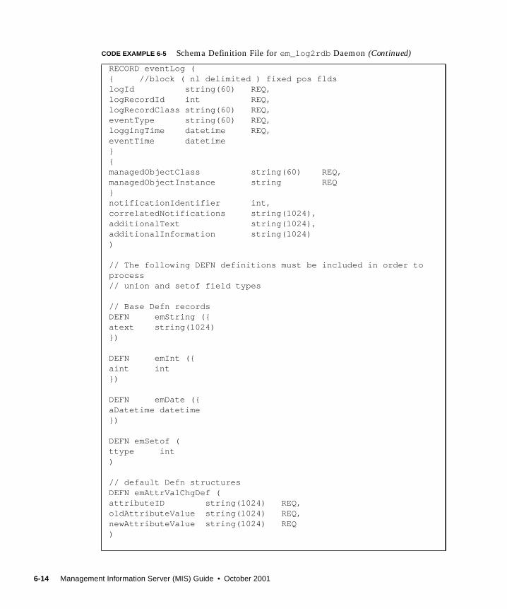
RECORD eventLog ({ //block ( nl delimited ) fixed pos fldslogId string(60) REQ,logRecordId int REQ,logRecordClass string(60) REQ,eventType string(60) REQ,loggingTime datetime REQ,eventTime datetime}{managedObjectClass string(60) REQ,managedObjectInstance string REQ}notificationIdentifier int,correlatedNotifications string(1024),additionalText string(1024),additionalInformation string(1024))
// The following DEFN definitions must be included in order toprocess// union and setof field types
// Base Defn recordsDEFN emString ({atext string(1024)})
DEFN emInt ({aint int})
DEFN emDate ({aDatetime datetime})
DEFN emSetof (ttype int)
// default Defn structuresDEFN emAttrValChgDef (attributeID string(1024) REQ,oldAttributeValue string(1024) REQ,newAttributeValue string(1024) REQ)
CODE EXAMPLE 6-5 Schema Definition File for em_log2rdb Daemon (Continued)
6-14 Management Information Server (MIS) Guide • October 2001

// Record definitionsRECORD objectCreationRecord (soureceIndicator string(40),attributeIdentifierList string(1024) // actually setofattributeId)
RECORD objectDeletionRecord (soureceIndicator string(40),attributeIdentifierList string(1024) // actually setofattributeId)
RECORD emAlarmRecord (probableCause string REQ,perceivedSeverity string(20) REQ,specificProblems string(1024),backedUpStatus bool,backUpObject string(1024),trendIndication string(20),thresholdInfo string(1024),stateChangeDefinition DREF(emAttrValChgDef),monitoredAttributes string(1024),proposedRepairActions string(1024),ackState string(10),ackTime datetime,ackOperator string(60),ackText string(1024),clearState string(10),clearTime datetime,clearOperator string(60),clearText string(1024),displayState string(12),displayTime datetime,displayOperator string(60),displayText string(1024))
RECORD attributeValueChangeRecord (attributeValueChangeDefinition setof(emAttrValChgDef) REQ,sourceIndicator string(30),// attributeIdentifierList stringattributeIdentifierList setof(emString))
RECORD relationshipChangeRecord (recordChangeDefinition string(1024) REQ,
CODE EXAMPLE 6-5 Schema Definition File for em_log2rdb Daemon (Continued)
Chapter 6 Managing Event Logs 6-15

sourceIndicator string(30),attributeIdentifierList setof(emString))
RECORD emInternetAlarmRecord (probableCause string,attributeIdentifierList string(1024),objectInstanceList string(1024),ackState string(10),ackTime datetime,ackOperator string(60),ackText string(1024),clearState string(10),clearTime datetime,clearOperator string(60),clearText string(1024),displayState string(12),displayTime datetime,displayOperator string(60),displayText string(1024),accessControlInfo string(1024),snmpVarBindList string(1024),transportDomain string(1024),transportAddress string(1024))
RECORD nerveCenterAlarmRecord (probableCause string,perceivedSeverity string(20),specificProblems string(1024),backedUpStatus bool,backUpObject string(1024),trendIndication string(20),thresholdInfo string(1024),stateChangeDefinition DREF(emAttrValChgDef),monitoredAttributes string(1024),proposedRepairActions string(1024),ackState string(10),ackTime datetime,ackOperator string(60),ackText string(1024),clearState string(10),clearTime datetime,clearOperator string(60),clearText string(1024),displayState string(12),displayTime datetime,
CODE EXAMPLE 6-5 Schema Definition File for em_log2rdb Daemon (Continued)
6-16 Management Information Server (MIS) Guide • October 2001

6.6.2.3 Database Schema Mapping
Common attributes of eventLog are stored in a single table named eventLog . One
table is defined for storing specific attributes of any one class of records. These
records are related to the eventLog with a key made up of
logID(coded)+logRecordId . Coded logID is a number assigned by the
em_log2rdb daemon and can be found in Solstice EM database tables.
For each log record of a known type, one record is created in the eventLog table
and one is created in the corresponding table of that type. In CODE EXAMPLE 6-5,
probableCause and perceivedSeverity fields are stored in emAlarmRecordtable, while all other common fields are stored in eventLog table.
Special handling is provided for lists of common items. Each list, called a SETOF, is
delimited in the log history records by {} and stored in a separate table, the
structure of which corresponds to the fields in the list.
For every attribute that is present, a record is created in a table structured to hold
lists of changes.
The following figure shows an Entity Relationship (ER) diagram for the log record
database. An internal primary key em_this_rn and an internal foreign key
em_key_rn are used to relate the common part of a log record with its type-specific
information.
displayOperator string(60),displayText string(1024),mosiSeverity int,mosiStateID int)
CODE EXAMPLE 6-5 Schema Definition File for em_log2rdb Daemon (Continued)
Chapter 6 Managing Event Logs 6-17

FIGURE 6-2 Entity Relationship Model for Log Record Database
Log Record Types
The log record types supported by the platform are as follows:
■ attributeValueChangeRecord■ emAlarmRecord■ objectCreationRecord■ objectDeletionRecord■ relationshipChangeRecord■ stateChangeRecord■ emInternetAlarmRecord■ nerveCenterAlarmRecord
6.6.2.4 Database Tables
The following table lists the tables created by the em_log2rdb daemon. The tables
that are created are specified in the configuration file. These tables correspond to the
log record types and contain miscellaneous system information. The following is a
list of the database tables:
■ eventLog■ emString
eventLog
em_this_rn
emAlarmRecord
em_this_rn
objectCreationRecord
emSetof
em_this_rn
em_key_rn
emDate
em_this_rn
em_key_rn
......
...
...
...
emString
em_this_rn
em_key_rn...
emInt
em_this_rn
em_key_rn
...
em_this_rn
6-18 Management Information Server (MIS) Guide • October 2001
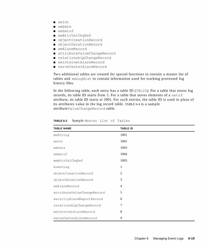
■ emInt■ emDate■ emSetof■ emAttrValChgDef■ objectCreationRecord■ objectDeletionRecord■ emAlarmRecord■ attributeValueChangeRecord■ relationshipChangeRecord■ emInternetAlarmRecord■ nerveCenterAlarmRecord
Two additional tables are created for special functions to contain a master list of
tables and emLogHist to contain information used for tracking processed log
history files.
In the following table, each entry has a table ID (TBLID ). For a table that stores log
records, its table ID starts from 1. For a table that stores elements of a setofattribute, its table ID starts at 1001. For such entries, the table ID is used in place of
its attributes value in the log record table. TABLE 6-4 is a sample
attributeValueChangeRecord table.
TABLE 6-3 Sample Master List of Tables
TABLE NAME TABLE ID
emString 1001
emInt 1002
emDate 1003
emSetof 1004
emAttrValChgDef 1005
eventLog 1
objectCreationRecord 2
objectDeletionRecord 3
emAlarmRecord 4
attributeValueChangeRecord 5
securityAlarmReportRecord 6
relationshipChangeRecord 7
emInternetAlarmRecord 8
nerveCenterAlarmRecord 9
Chapter 6 Managing Event Logs 6-19

The attributeValueChangeRecord table has two sets of columns:
■ attributeValueChangeDefinition■ attributeIdentifierList
The elements for the attributeValueChangeDefinition column are stored in the
emAttrValChgDef table, so 1005 is stored as the value of this column by looking up
TABLE 6-3. For this reason, 1001 is stored as the value for the
attributeIdentifierList column, since its elements are strings. The relationship
between each element and its owner record is stored in the emSetof table.
Tables 6-5 through 6-12 illustrate specific system information for the database tables
that are created by the em_log2rdb daemon.
TABLE 6-4 Sample attributeValueChangeRecord
em_this_rn attributeValueChangeDefinition Source Indicator attributeIdentifierList
3 1005 managementOperation 1001
4 1005 managementOperation 1001
5 1005 managementOperation 1001
6 1005 managementOperation 1001
7 1005 managementOperation 1001
8 1005 managementOperation 1001
9 1005 managementOperation 1001
12 1005 managementOperation 1001
16 1005 managementOperation 1001
20 1005 managementOperation 1001
24 1005 managementOperation 1001
28 1005 managementOperation 1001
TABLE 6-5 eventLog
Field NameMandatoryor Optional Field Type
FieldLength Comments
em_This_Rn Mandatory int 4 Primary Key
logID Mandatory varchar < 255 Key Field (for example,
“AlarmLog ”)
logRecordId Mandatory int 4 Key Field (for example, “1”)
logRecordClass Mandatory varchar < 255 For example,
“objectCreationRecord ”
6-20 Management Information Server (MIS) Guide • October 2001

eventType Mandatory varchar < 255 For example,
“objectCreation ”
loggingTime Mandatory time “yyyymmddhhmmss” format
in the log file
managedObjectClass Mandatory varchar < 255 For example,
“emApplicationInstance ”
managedObjectInstance Mandatory varchar < 255 For example,
‘/systemId=”vidhi”’
eventTime optional time “yyyymmddhhmmss” format
on file
notificationIdentifier optional int 4
correlatedNotifications optional varchar < 255
additionalText optional varchar < 255
additionalInformation optional varchar < 255
TABLE 6-6 objectCreationRecord
Field NameMandatory orOptional Field Type
FieldLength Comments
em_This_Rn Mandatory int 4 Primary Key
sourceIndicator Optional char 1 ‘1’=resourceOperation
‘2’=managementOperation
‘3’=unknown
attributeIdentifierList Optional boolean 1 SET OF AttributeId*
TABLE 6-7 objectDeletionRecord
Field NameMandatory orOptional Field Type
FieldLength Comments
em_This_Rn Mandatory int 4 Primary Key
sourceIndicator Optional char 1 ‘1’=resourceOperation
‘2’=managementOperation
‘3’=unknown
attributeList Optional boolean 1 SET OF Attribute
TABLE 6-5 eventLog
Field NameMandatoryor Optional Field Type
FieldLength Comments
Chapter 6 Managing Event Logs 6-21

TABLE 6-8 emAlarmRecord
Field NameMandatory orOptional Field Type
FieldLength Comments
em_This_Rn Mandatory int 4 Primary Key
probableCause Mandatory varchar < 255 Choice syntax in dmi.asn1
perceivedSeverity Mandatory char 1 ‘1’=indeterminate, ‘2’=critical
‘3’=major
‘4’=minor
‘5’=warning
‘6’=cleared
specificProblems Optional varchar < 255 Optional of alarmRecord
backedUpStatus Optional boolean 1 Optional of alarmRecord
backUpObject Optional varchar < 255 Object instance
trendIndication Optional char 1 ‘1’=lessSevere, ‘2’=noChange,
‘3’= moreSevere
thresholdInfo Optional varchar < 255
stateChangeDefinition Optional boolean 1 Type avChangeDefinition
monitoredAttributes Optional varchar < 255
proposedRepairActions Optional varchar < 255
ackState Mandatory char 1 ‘1’=unAcked
‘2’=acked
ackTime Mandatory time
ackOperator Mandatory varchar
ackText Mandatory varchar < 255
clearState Mandatory char 1 ‘1’=unCleared
‘2’=cleared
clearTime Mandatory time
clearOperator Mandatory varchar < 255
clearText Mandatory varchar < 255
displayState Mandatory char 1 ‘1’=unDisplayed,
‘2’=displayed
displayTime Mandatory time
displayOperator Mandatory varchar < 255
displayText Mandatory varchar < 255
6-22 Management Information Server (MIS) Guide • October 2001

TABLE 6-9 attributeValueChangeRecord
Field NameMandatory orOptional Field Type
FieldLength Comments
em_This_Rn Mandatory int 4 Primary Key
avChangeDefinition Mandatory boolean 1
sourceIndicator Optional char 1 ‘1’=resourceOperation,
‘2’=managementOperation,
‘3’=unknown
attributeIdentifierList Optional boolean 1 SET OF AttributeId
TABLE 6-10 relationshipChangeRecord
Field NameMandatory orOptional
FieldType
FieldLength Comments
em_This_Rn Mandatory int 4 Primary Key
rcChangeDefinition Mandatory varchar < 255 avChangeDefinition
sourceIndicator Optional char 1 ‘1’=resourceOperation
‘2’=managementOperation
‘3’=unknown
attributeIdentifierList Optional boolean 1 SET OF AttributeId
TABLE 6-11 emInternetAlarmRecord
Field NameMandatory orOptional Field Type
FieldLength Comments
em_This_Rn Mandatory int 4 Primary Key
ackState Mandatory char 1 ‘1’=unAcked
‘2’=acked
ackTime Mandatory time
ackOperator Mandatory varchar < 255
ackText Mandatory varchar < 255
clearState Mandatory char 1 ‘1’=unCleared
‘2’=cleared
clearTime Mandatory time
clearOperator Mandatory varchar < 255
clearText Mandatory varchar < 255
displayState Mandatory char 1 ‘1’=unDisplayed
‘2’=displayed
Chapter 6 Managing Event Logs 6-23

displayTime Mandatory time
displayOperator Mandatory varchar < 255
displayText Mandatory varchar < 255
probableCause Mandatory varchar < 255
attributeIdentifierList Optional boolean 1
objectInstanceList Optional boolean 1
TABLE 6-12 nerveCenterAlarmRecord
Field NameMandatory orOptional Field Type
FieldLength Comments
em_This_Rn Mandatory int 4 Primary Key
probableCause Mandatory varchar < 255
perceivedSeverity Mandatory char 1 ‘1’=indeterminate
‘2’=critical
‘3’=major
‘4’=minor
‘5’=warning
‘6’=cleared
specificProblems Optional varchar < 255 An optional alarmRecord
backedUpStatus Optional char 1 All fields of em_alarm_recstart
backUpObject Optional varchar < 255
trendIndication Optional char 1 ‘1’=lessSevere
‘2’=noChange
‘3’= moreSevere
thresholdInfo Optional varchar < 255
stateChangeDefinition Optional boolean 1 avChangeDefinition
monitoredAttributes Optional varchar < 255
proposedRepairActions
Optional varchar < 255
ackState Mandatory char 1 ‘1’=unAcked
‘2’=acked
ackTime Mandatory time
ackOperator Mandatory varchar < 255
TABLE 6-11 emInternetAlarmRecord (Continued)
Field NameMandatory orOptional Field Type
FieldLength Comments
6-24 Management Information Server (MIS) Guide • October 2001
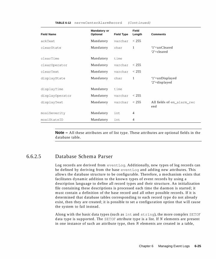
Note – All these attributes are of list type. These attributes are optional fields in the
database table.
6.6.2.5 Database Schema Parser
Log records are derived from eventLog . Additionally, new types of log records can
be defined by deriving from the base eventLog and adding new attributes. This
allows the database structure to be configurable. Therefore, a mechanism exists that
facilitates dynamic addition to the known types of event records by using a
description language to define all record types and their structure. An initialization
file containing these descriptions is processed each time the daemon is started; it
must contain a definition of the base record and all other possible records. If it is
determined that database tables corresponding to each record type do not already
exist, then they are created; it is possible to set a configuration option that will cause
the system to fail instead.
Along with the basic data types (such as int and string ), the more complex SETOFdata type is supported. The SETOFattribute type is a list. If N elements are present
in one instance of such an attribute type, then N elements are created in a table,
ackText Mandatory varchar < 255
clearState Mandatory char 1 ‘1’=unCleared
‘2’=cleared
clearTime Mandatory time
clearOperator Mandatory varchar < 255
clearText Mandatory varchar < 255
displayState Mandatory char 1 ‘1’=unDisplayed
‘2’=displayed
displayTime Mandatory time
displayOperator Mandatory varchar < 255
displayText Mandatory varchar < 255 All fields of em_alarm_recend
mosiSeverity Mandatory int 4
mosiStateID Mandatory int 4
TABLE 6-12 nerveCenterAlarmRecord (Continued)
Field NameMandatory orOptional Field Type
FieldLength Comments
Chapter 6 Managing Event Logs 6-25
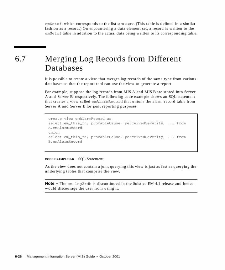
emSetof , which corresponds to the list structure. (This table is defined in a similar
fashion as a record.) On encountering a data element set, a record is written to the
emSetof table in addition to the actual data being written to its corresponding table.
6.7 Merging Log Records from DifferentDatabasesIt is possible to create a view that merges log records of the same type from various
databases so that the report tool can use the view to generate a report.
For example, suppose the log records from MIS A and MIS B are stored into Server
A and Server B, respectively. The following code example shows an SQL statement
that creates a view called emAlarmRecord that unions the alarm record table from
Server A and Server B for joint reporting purposes.
CODE EXAMPLE 6-6 SQL Statement
As the view does not contain a join, querying this view is just as fast as querying the
underlying tables that comprise the view.
Note – The em_log2rdb is discontinued in the Solstice EM 4.1 release and hence
would discourage the user from using it.
create view emAlarmRecord asselect em_this_rn, probableCause, perceivedSeverity, ... fromA.emAlarmRecordunionselect em_this_rn, probableCause, perceivedSeverity, ... fromB.emAlarmRecord
6-26 Management Information Server (MIS) Guide • October 2001

CHAPTER 7
Obtaining Data From the Database
This chapter provides information about querying the data in Solstice Enterprise
Manager (Solstice EM) database.
This chapter describes the following topics:
■ Section 7.1 “Prerequisite Knowledge” on page 7-1
■ Section 7.2 “Querying the Database” on page 7-1
■ Section 7.3 “Using Third-Party Software” on page 7-3
7.1 Prerequisite KnowledgeTo perform database queries, you will need to know the following:
■ SQL or an application that provides a graphical user interface for SQL commands
■ The database schema provided in Appendix A
7.2 Querying the DatabaseAdvanced users can query the database for information from database tables. The
two methods for obtaining data from the database are as follows:
■ SQL and the em_sql command
■ A third-party software program
7-1

Note – The DBTools.h++ support is discontinued in the Solstice EM 4.1 and
subsequent releases. If you have DBTools.h++ and wish to use for accessing the
databases through application, you can do so.
All access control restrictions and privileges apply to database queries, regardless of
the querying method.
Using the em_sql command and standard SQL commands, you can query the
Solstice EM database (emdb) directly.
If you are using your login name to start em_sql , make sure that the user name was
created in Access Control, regardless of whether Access Control is on or off.
If Solstice EM is installed with Access Control off, you cannot run em_sql because
the user was not created.
Caution – Changes to the database (adding, modifying, and deleting) should not be
made using the em_sql command or SQL commands. Any changes made to the
database in this manner may corrupt the contained management information.
Changes would only be allowed in this manner if you were executing the file
em_sql command as the Database Administrator UNIX user.
If you want to perform the same or a similar query often, you can type SQL
commands in a file and redirect them to em_sql using the normal shell
input/output redirection methods. System prompts will not display.
▼ To Query the Database
1. If you have installed the product in the default directory, log in to the database(local or remote) by typing the following command:
/opt/SUNWconn/bin/em_sql <login_name>/ <password>@<host name>
If you omit the password, you will be prompted for it. If you omit the login name,
em_sql will use your current login.
Note – If you installed the product in a different directory, substitute your partition
name for /opt .
Your user login name determines the tables to which you have access. If you want to
connect to a remote server, type the server name. If you omit the server name, the
system assumes the database server is local.
7-2 Management Information Server (MIS) Guide • October 2001

2. Enter the SQL command and optional parameters to perform a database query.
Refer to any standard reference manual for SQL command syntax.
3. Type a semicolon and press the Return key to initiate the query.
The system queries the database and displays the result on your computer’s
monitor. The results can span several lines. Refer to the following code example.
CODE EXAMPLE 7-1 System Queries
4. To exit SQL, type quit or Control-D at the prompt.
7.3 Using Third-Party SoftwareMany third-party programs that simplify database query are compatible with the
database used by Solstice EM. Third party programs are compatible if they are
ODBC Level 1 compliant or are compliant with ANSI and ISO SQL92 standard at
entry level.
# em_sqlConnecting to emdb as root...em_sql> select agent_name[1,16], trans_addr[1,25]2> from snmp_agents;
agent_name trans_addr----------- ----------------------------crow1 129.555.075.123:000161sherwood 129.555.075.456:000161orion 129.555.075.789:0001613 rowsem_sql>
Chapter 7 Obtaining Data From the Database 7-3

7-4 Management Information Server (MIS) Guide • October 2001

CHAPTER 8
Adding New Data Definitions
You can add new data definitions to MIS, which allows you to use
Solstice Enterprise Manager (Solstice EM) to manage objects described by those
definitions. For instance, you may add the MIB for a new device you have included
in your network, add schemas from SunNet Manager, define a new object class for
an application you have developed, or create a new event type.
The MIS must get the information it needs about all known objects from GDMO
files, which you can create from scratch, or create by converting from other formats
such as MIB and SNM schema. Solstice EM includes conversion utilities and
compilers to help you get the information into GDMO form. After you create or
obtain your data definition files, you can use the Load Data Definitions (LDD) tool
to convert, compile, load, and link files so that the information is usable by MIS. The
LDD tool is accessible from the Solstice EM Administration window.
This chapter describes the following topics:
■ Section 8.1 “Adding a MIB” on page 8-2
■ Section 8.2 “Adding SunNet Manager Schemas” on page 8-3
■ Section 8.3 “Adding Managed Object Classes” on page 8-5
■ Section 8.4 “Configuring Notifications for Managed Objects That Reside in the
Solstice EM MIS” on page 8-11
■ Section 8.4.5 “Adding Event Types” on page 8-14
■ Section 8.5 “Creating GDMO Documents for New Events” on page 8-15
■ Section 8.6 “Logging New Event Types” on page 8-16
■ Section 8.7 “Loading a New Event Type” on page 8-17
8-1

8.1 Adding a MIB
▼ To Add a MIB to MIS
1. Locate the MIB file for the network device you want to manage.
You must also have available any MIB files that are referenced by the MIB file you
are adding.
2. Translate and load the MIB into MIS.
3. Optionally, view the MIB in Solstice EM to see that it was successfully loaded.
▼ To Translate and Load a MIB
1. Start the LDD tool in one of the following ways:
Click the LDD button in the Administration Tools window, or enter the following
command at a command line prompt:
em_loaddefs &
2. Type the name(s) of the MIB files you want to add, or click Browse to select thefiles.
Select files having the file extension.mib , making sure to include MIB files
referenced by the one you are adding to MIS.
3. Select “Structure the GDMO data in MIS for: Retrieving remote deviceinformation only.”
As you are adding MIB information about a specific device, you will not need to
create objects from this MIB. Refer to TABLE 8-6 for descriptions of the available
options.
8-2 Management Information Server (MIS) Guide • October 2001

4. Click Load to begin converting and loading the MIB.
The Activity Log shows the output of the programs and compilers working on the
files.
LDD starts the translator em_cmib2gdmo to convert the MIB to a GDMO document.
LDD then starts the em_asn1 and em_gdmocompilers to import the data to MIS,
and the files are placed in the directories $EM_HOME/etc/gdmo and $EM_HOME/etc/asn1 . Files placed in these directories are read by MIS on startup.
If the MIB references another MIB that you did not include in the list of files to
convert, LDD searches for the referenced MIB file in the current working directory
and the MDR. If the referenced MIB file is found the tool restarts em_cmib2gdmo ,
supplying the names of both MIB files. If the referenced MIB is not found, an error
message is displayed and processing stops.
If an error occurs during the translation, LDD displays a message describing the
error and stops processing the affected file.
5. If an error occurs, select the affected file in Files with Errors, and click Edit.
Your default editor starts and opens the selected file.
6. When you finish editing, save the file and exit the editor.
LDD processes the file again.
7. Click Close in the LDD dialog box when processing is complete.
▼ To View the New MIB in Solstice EM
● In SNMP Browser, click View ➔ Show All Documents to see all MIBs and theirattributes.
You can start the SNMP Browser from the Network Tools window.
8.2 Adding SunNet Manager Schemas
▼ To Add an SNM Schema
1. Locate the schema file.
2. Translate and load the schema file into MIS.
3. Optionally, view the schema in Solstice EM to see that it was successfully loaded.
Chapter 8 Adding New Data Definitions 8-3

▼ To Translate and Load SNM Schemas
1. Start the Load Management Information tool in one of the following ways:
Click Load Data Definitions in the Administration Tools window, or enter the
following command at a command line prompt:
em_loaddefs &
2. Type the name(s) of the schema files you want to add, or click Browse to select thefiles.
Select files having the file extension .schema .
3. Select “Structure the GDMO data in MIS for: Retrieving remote deviceinformation only.”
Since you are adding information about a specific device, you cannot create objects
from this schema. Refer to TABLE 8-6 for descriptions of the available options.
4. Click Load to begin converting and loading the schema.
The Activity Log shows the output of the programs and compilers working on the
files.
LDD starts the translator em_snm2gdmoto convert the schema to a GDMO
document. If an error occurs during the translation, LDD displays a message
describing the error and allows you to edit the file using your default file editor.
When you finish editing and save the file, LDD restarts the translation.
Translation of an SNM schema requires a unique object identification number. This
number will be associated with the agent and/or elements described in the schema,
and it must not be the same as any other OID number already in use in the system.
LDD determines a unique OID number for the schema.
After em_snm2gdmocreates a GDMO file, LDD starts the em_asn1 and em_gdmocompilers to import the data to MIS, and the files are placed in the directories
$EM_HOME/etc/gdmo and $EM_HOME/etc/asn1
5. Click Close in the Data Definitions Loading dialog when processing is complete.
▼ To View the New Schema in Solstice EM
● In SNMP Browser, click View ➔ Show All Attributes.
You can start the RPC/CMIP Browser from the Network Tools window.
8-4 Management Information Server (MIS) Guide • October 2001

8.3 Adding Managed Object Classes
Note – This section explains, from an application development perspective, how a
developer can add a new managed object to the Solstice EM MIS. Information
regarding the internal representation of the managed object is for clarification only.
A managed object contains a set of services and attributes that describes a type of
managed resource. It defines what type of data members exist, and the various
methods which will perform various operations.
In the Solstice EM MIS, an instance of a managed object will represent a particular
managed resource - data describing the resource is contained in the attributes, and
the associated behaviors operate on this data. Therefore, you will first want to create
an appropriate managed object class that accurately defines the type of managed
resource you wish to model. Next, actual instances of this managed object can be
created in the MIS.
To represent the managed object within the Solstice EM MIS, a Managed Object
Class (MOC) is created. When an instance of a managed object needs to be created in
the MIS to represent a managed resource, the MOC is consulted to determine how to
create the instance (so that what kinds of attributes will it have, and what are its
behaviors). The representation of an instance of a managed resource within the
Solstice EM MIS is known as a Managed Object Instance (MOI).
Both the MOC and MOI described above are implemented in the Solstice EM MIS as
C++ classes. An overview of these are shown in the following figure.
FIGURE 8-1 Managed Object Implementation Components
Internal Enterprise ManagerManaged Object Class Implementation
GDMOdocument
ASN.1 documents
MDR
MIS
compiledannotation
code
A A
B
Representation
Managed objectclass
Managed objectInstance
Chapter 8 Adding New Data Definitions 8-5

The preceding figure shows the relationship of the components produced by the
developer to their position within the Solstice EM MIS.
The GDMO and ASN.1 documents that describe the managed object (A) are
represented in the MIS within the MDR. The annotation code that implements the
object behaviors (B) are linked to the MIS in the form of compiled code modules. The
annotation code is used by objects and is part of MIS.
The ObjMethMOC and ObjMethMOI objects are created dynamically by the MIS, as
needed. The ObjMethMOC is created when needed to represent an MOC; an
ObjMethMOI is used when an instance of a managed object is created to represent a
managed resource.
▼ To Add a New MOC to MIS
1. Determine what it is that you want to manage, and identify its characteristics.
2. Determine the attributes you need.
The attributes define the data about the managed object that is stored.
3. Determine if there are any existing MOCs that you can reuse with somemodification.
Inspect the GDMO documents available in the $EM_HOME/etc/gdmo directory.
$EM_HOMEis an environment variable set to the directory the Solstice EM product
was installed in, which is /opt/SUNWconn/em by default.
4. Implement MOC by writing or adapting a GDMO document and ASN.1document (if necessary).
5. Load the MOC into MIS using the Load Data Definitions (LDD).
8.3.1 Defining the Properties of an MOC
The components of an MOC are specified in a GDMO document and possibly one or
more ASN.1 documents. The GDMO document must contain the following:
■ MOC definition. This includes the name of the object class, and the attributes
which are in this MOC. A unique OID is also specified such that the MOC can be
identified in the MIT.
■ Attribute definitions. Each attribute within the MOC has its syntax defined, along
with a unique OID.
■ Name Binding definition. The naming attribute is identified in the name binding,
along with the various other pieces of information.
8-6 Management Information Server (MIS) Guide • October 2001

■ Notification definitions. These are optional, and define any notifications the MOC
should generate. The notifications can be ones from the set of predefined
notifications available within the MIS, or you can define your own. Predefined
notifications include such things as attribute value changes, object creation or
deletion, and various error, alarm, or violation conditions. Predefined
notifications are listed in TABLE 8-4.
If the GDMO document refers to any ASN.1 syntax notations, these ASN.1
documents must also exist. In most cases, the GDMO document will refer to syntax
defined in existing ASN.1 documents; however if new syntax is needed, the ASN.1
document must be created. The MOC, defined in the GDMO document, and the
naming attribute(s) will be referenced according to their unique OID values.
From a Solstice EM internal implementation perspective, the OID of the MOC is
specified and the appropriate definition is then loaded into the MIS to help in
creating the ObjMethMOC which represents the MOC definition. Remember that the
ObjMethMOC is a C++ class that represents an MOC within the MIS. The MIS gains
access to the MOC definition (from the GDMO document) by reading the definition
from the MDR. The GDMO document must be compiled into the MDR in order for
the MIS to find the definition.
8.3.1.1 Sample GDMO File
Developing C++ Applications includes information explaining the structure of a
GDMO file. This section shows only an example file.
In this example, the coffee.gdmo file contains the GDMO definition of the coffeemanaged object class.
The following code example is a copy of the coffee.gdmo GDMO definition file for
review and reference purposes. It describes the coffee MOC used in this chapter:
CODE EXAMPLE 8-1 Definition File for coffee.gdmo
MODULE “G2 Coffee Document”coffee MANAGED OBJECT CLASS
DERIVED FROM “Rec. X.721 | ISO/IEC 10165-2 : 1992” : top; CHARACTERIZED BY coffeePackage; REGISTERED AS { 1 2 3 4 5 6 3 1 };
coffeePackage PACKAGE BEHAVIOUR coffeePackageDefinition BEHAVIOUR DEFINED AS !This managed object class represents the coffee pot of Peet’s coffee in Jon and Kevin’s office!; ;
Chapter 8 Adding New Data Definitions 8-7
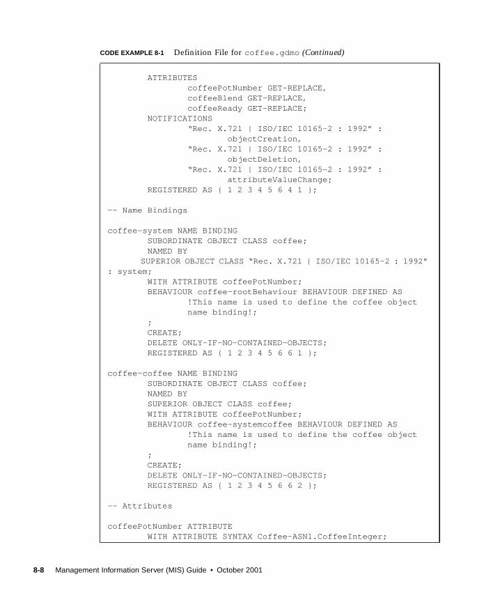
ATTRIBUTES coffeePotNumber GET-REPLACE, coffeeBlend GET-REPLACE, coffeeReady GET-REPLACE; NOTIFICATIONS “Rec. X.721 | ISO/IEC 10165-2 : 1992” : objectCreation, “Rec. X.721 | ISO/IEC 10165-2 : 1992” : objectDeletion, “Rec. X.721 | ISO/IEC 10165-2 : 1992” : attributeValueChange; REGISTERED AS { 1 2 3 4 5 6 4 1 };
-- Name Bindings
coffee-system NAME BINDING SUBORDINATE OBJECT CLASS coffee; NAMED BY
SUPERIOR OBJECT CLASS “Rec. X.721 | ISO/IEC 10165-2 : 1992”: system; WITH ATTRIBUTE coffeePotNumber; BEHAVIOUR coffee-rootBehaviour BEHAVIOUR DEFINED AS !This name is used to define the coffee object name binding!; ; CREATE; DELETE ONLY-IF-NO-CONTAINED-OBJECTS; REGISTERED AS { 1 2 3 4 5 6 6 1 };
coffee-coffee NAME BINDING SUBORDINATE OBJECT CLASS coffee; NAMED BY SUPERIOR OBJECT CLASS coffee; WITH ATTRIBUTE coffeePotNumber; BEHAVIOUR coffee-systemcoffee BEHAVIOUR DEFINED AS !This name is used to define the coffee object name binding!; ; CREATE; DELETE ONLY-IF-NO-CONTAINED-OBJECTS; REGISTERED AS { 1 2 3 4 5 6 6 2 };
-- Attributes
coffeePotNumber ATTRIBUTE WITH ATTRIBUTE SYNTAX Coffee-ASN1.CoffeeInteger;
CODE EXAMPLE 8-1 Definition File for coffee.gdmo (Continued)
8-8 Management Information Server (MIS) Guide • October 2001

8.3.1.2 Sample ASN.1 Definition File
The following code example is a copy of the coffee.asn1 ASN.1 definition file. It
is used to describe the syntax and encoding rules for the coffee MOC:
MATCHES FOR EQUALITY; BEHAVIOUR coffeePotNumberBehaviour BEHAVIOUR DEFINED AS !This is the naming attribute for the coffee object. This will always be 1 until Jon and Kevin get another pot working.!; ; REGISTERED AS { 1 2 3 4 5 6 7 1 };
coffeeBlend ATTRIBUTE WITH ATTRIBUTE SYNTAX Coffee-ASN1.CoffeeString; MATCHES FOR EQUALITY; BEHAVIOUR coffeeBlendBehaviour BEHAVIOUR DEFINED AS !This is the blend of coffee that is brewing in the current pot, undoubtedly Peets, and probably French or Italian.!; ; REGISTERED AS { 1 2 3 4 5 6 7 2 };
coffeeReady ATTRIBUTE WITH ATTRIBUTE SYNTAX Coffee-ASN1.CoffeeInteger; MATCHES FOR EQUALITY; BEHAVIOUR coffeeReadyBehaviour BEHAVIOUR DEFINED AS !If this attribute is true there is coffee in the pot, you better hurry!; ; REGISTERED AS { 1 2 3 4 5 6 7 3 };END
CODE EXAMPLE 8-2 Definition File for coffee.asn1
-- Asn1 Definitions needed by the coffee classCoffee-ASN1 { 1 2 3 4 5 1 }
DEFINITIONS ::=BEGIN
CoffeeInteger ::= INTEGER
CoffeeString ::= GraphicString
CODE EXAMPLE 8-1 Definition File for coffee.gdmo (Continued)
Chapter 8 Adding New Data Definitions 8-9

8.3.2 Loading an MOC into MIS
Once you have composed the GDMO and ASN.1 files, the object class is ready to be
incorporated into MIS, as described in the following procedure.
▼ To Load a New Object Class
1. Start the LDD tool in one of the following ways:
Click Load Data Definitions in the Administration Tools window, or enter the
following command at a command line prompt:
em_loaddefs &
2. Type the names of the GDMO and ASN.1 files you want to add, or click Browse toselect the files.
3. Select a method for structuring the GDMO data in MIS.
Refer to TABLE 8-6 for descriptions of the available options.
4. Click Load to begin processing the files for loading into MIS.
The Activity Log shows the output of the programs and compilers working on the
files.
The em_asn1 and em_gdmocompilers are run. If you specified in the preceding step
that you want to be able to create volatile objects, em_compose_oc is run. If you
specified that you want to be able to create persistent objects, em_compose_poc is
run. In either case, em_load_name_bindings is also run.
The compiled GDMO files are placed in the $EM_HOME/etc/gdmo directory. The
compiled ASN.1 files are placed in the $EM_HOME/etc/asn1 directory. All object
classes contained in these directories are loaded into MIS each time it starts.
If an error occurs during processing, LDD displays a message describing the error,
and the affected files are listed in Files with Errors.
5. If errors occur, select a file in Files with Errors, and click Edit to open the file withyour default text editor.
If you do not have a default text editor, vi is started.
CoffeeBoolean ::= BOOLEAN
END
CODE EXAMPLE 8-2 Definition File for coffee.asn1
8-10 Management Information Server (MIS) Guide • October 2001

6. When you finish editing, save the file, and LDD restarts processing the files.
7. Click Close in the Data Definitions Loading dialog when processing is complete.
8. Go to the default directory and, as root , run the em_services command to restartMIS as follows:
cd $EM_HOME/bin
./em_services -start
8.4 Configuring Notifications for ManagedObjects That Reside in the Solstice EMMISThe configuration file $EM_RUNTIME/conf/em_notif.cfg contains notification
configuration entries for objects that reside in the Solstice EM MIS. Adding
notification configuration entries enables you to control the generation of the
following types of notifications:
■ objectCreation (M-CREATE)
■ objectDeletion (M-DELETE)
■ attributeValueChange and stateChange (M-Set)
The configuration file $EM_RUNTIME/conf/em-notif.cfg consists of one or more
lines, each containing a complete specification for an entry. There are three types of
entries.
■ CREATE■ DELETE■ SET
Note – Invalid lines are ignored and a warning message shown in the Solstice EM
MIS log (em_mis.log) .
The configuration file is read and entries loaded each time the MIS is restarted. The
following subsections describe the format of the configuration file.
8.4.1 Comments
Lines beginning with “//” are considered to be comments and are ignored.
Chapter 8 Adding New Data Definitions 8-11

8.4.2 Format of a CREATEEntry
A CREATEentry defines the notifications that are generated when an instance of the
specified object class (<object_class_OID>) is created. The valid values for
<create_notif_config_value> are described in the following table.
Note – The default behavior for object classes that do not have a CREATEentry is for
an objectCreation notification with no attributeList to be generated.
In the following example, an objectCreation notification is generated when an
instance of the object class whose OID is 1.3.6.1.4.1.42.2.2.2.200.3.3. is created. The
objectCreation notification contains an attributeList .
CREATE <object_class_OID> <create_notif_config_value>
TABLE 8-1 Valid Values for <create_notif_config_value>
Value Description
NOTIF_NONE No notification
NOTIF_NO_ATTRLIST objectCreation notification. Does not contain anattributeList.
NOTIF_ATTRLIST objectCreation notification. Contains anattributeList.
CREATE 1.3.6.1.4.1.42.2.2.2.200.3.3 NOTIF_ATTRLIST
8-12 Management Information Server (MIS) Guide • October 2001

8.4.3 Format of a DELETEEntry
A DELETEentry defines the notifications that are generated when an instance of the
specified object class (<object_class_OID>) is deleted. The valid values for
<delete_notif_config_value> are described in the following table..
Note – The default behavior for object classes that do not have a DELETEentry is for
an objectDeletion notification with no attributeList to be generated.
In the following example, an objectDeletion notification is generated when an
instance of the object class whose OID is 1.3.6.1.4.1.42.2.2.2.200.3.3 is deleted. The
objectDeletion notification does not contain an attributList .
8.4.4 Format of a SET Entry
A SET entry defines the notifications that are generated when the specified object
class (<object_class_OID>) are described in the following table..
DELETE 1.3.6.1.4.1.42.2.2.2.200.3.3 NOTIF_ATTRLIST
TABLE 8-2 Valid Values for <delete_notif_config_value>
Value Description
NOTIF_NONE No notification
NOTIF_NO_ATTRLIST objectDeletion notificationDoes not contain an attributeList.
SET <object_class_OID> <attribute_OID> <set_notif_config_value>
TABLE 8-3 Valid Values forset_notif_config_value
Value Description
NOTIF_NONE Specified attribute does not appear in any notification.
NOTIF_AVC Specified attribute appears in attributeValuChangenotifications.
NOTIF_STC Specified attribute appears in stateChangenotifications.
Chapter 8 Adding New Data Definitions 8-13
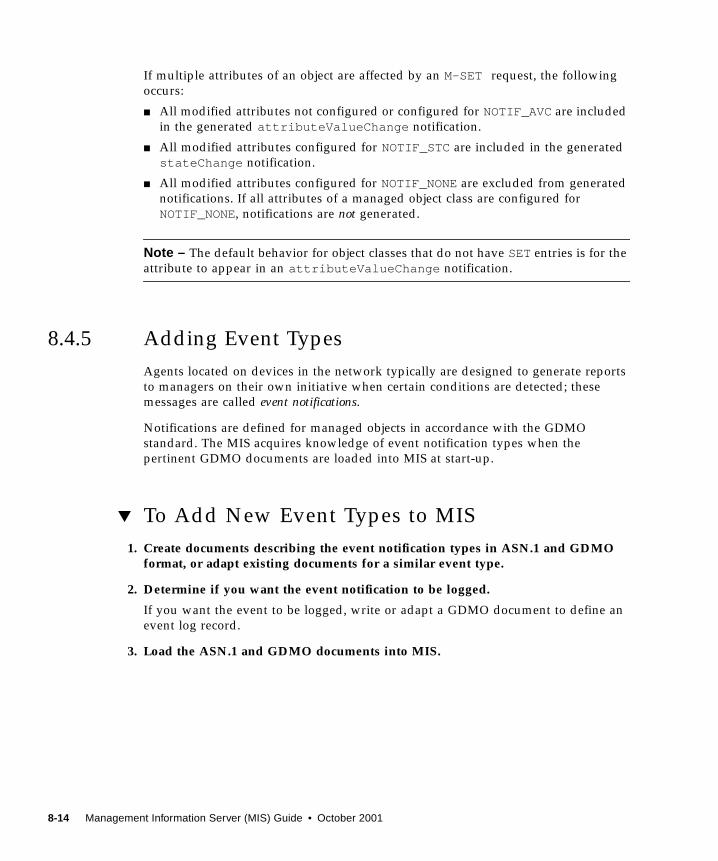
If multiple attributes of an object are affected by an M-SET request, the following
occurs:
■ All modified attributes not configured or configured for NOTIF_AVCare included
in the generated attributeValueChange notification.
■ All modified attributes configured for NOTIF_STC are included in the generated
stateChange notification.
■ All modified attributes configured for NOTIF_NONEare excluded from generated
notifications. If all attributes of a managed object class are configured for
NOTIF_NONE, notifications are not generated.
Note – The default behavior for object classes that do not have SETentries is for the
attribute to appear in an attributeValueChange notification.
8.4.5 Adding Event Types
Agents located on devices in the network typically are designed to generate reports
to managers on their own initiative when certain conditions are detected; these
messages are called event notifications.
Notifications are defined for managed objects in accordance with the GDMO
standard. The MIS acquires knowledge of event notification types when the
pertinent GDMO documents are loaded into MIS at start-up.
▼ To Add New Event Types to MIS
1. Create documents describing the event notification types in ASN.1 and GDMOformat, or adapt existing documents for a similar event type.
2. Determine if you want the event notification to be logged.
If you want the event to be logged, write or adapt a GDMO document to define an
event log record.
3. Load the ASN.1 and GDMO documents into MIS.
8-14 Management Information Server (MIS) Guide • October 2001

8.5 Creating GDMO Documents for NewEventsSolstice EM includes a number of event notifications, listed in the following table.
You may use the GDMO files for these event notifications to copy and adapt GDMO
templates for events similar to ones you want to add. Refer to the Developing C++Applications for information about the structure of a GDMO document.
TABLE 8-4 Event Notifications in Solstice EM
Standarddefining event Event Notification Classes GDMO file defining events
CMIP objectCreationobjectDeletionattributeValueChangerelationshipChangestateChangecommunicationsAlarmenvironmentalAlarmequipmentAlarmintegrityViolationoperationalViolationphysicalViolationprocessingErrorAlarmqualityofServiceAlarmsecurityServiceOrMechanismAlarmtimeDomainViolation
dmi.gdmo
ISO-Internet
Management
Coexistence
(IIMC)
internetAlarm iimcManagementDoc1.gdmo
SNMP coldStartTrapwarmStartTraplinkDownTraplinkUpTrapauthenticationFailureTrapegpNeighborLossTrapenterpriseSpecificTrap
snmp_traps.gdmo
EM snmAlarmEventsnmAlarmTrap
nerveCenterAlarm
mpa.gdmo
nc.gdmo
Chapter 8 Adding New Data Definitions 8-15

ASN.1 documents are only necessary if the GDMO document uses syntax that is not
described in existing ASN.1 documents in $EM_HOME/etc/asn1 .
8.6 Logging New Event TypesEach default event notification object class has associated with it an additional object
class for a log record. The log record object class allows an event of that type to be
logged.
The default mapping of event notification classes to log record classes is shown in
the following table.
TABLE 8-5 Default Mapping of Notifications to Event Log Records
Event NotificationObject Class Event Log Record Object ClassGDMO forLog Record
attributeValueChange attributeValueChangeRecord dmi.gdmo
objectCreation objectCreationRecord
objectDeletion objectDeletionRecord
relationshipChange relationshipChangeRecord
stateChange stateChangeRecord
integrityViolation securityAlarmReportRecord
operationalViolation securityAlarmReportRecord
physicalViolation securityAlarmReportRecord
securityServiceOrMechanismAlarm securityAlarmReportRecord
timeDomainViolation securityAlarmReportRecord
communicationsAlarm emAlarmRecord emalarm.gdmo
environmentalAlarm emAlarmRecord
equipmentAlarm emAlarmRecord
processingErrorAlarm emAlarmRecord
qualityofServiceAlarm emAlarmRecord
internetAlarm emInternetAlarmRecord
nerveCenterAlarm nerveCenterAlarmRecord nc.gdmo
8-16 Management Information Server (MIS) Guide • October 2001

You can use one of the existing log record classes, or provide a custom log record
class definition. A single log record class can be used to log a group of event
notifications.
If you elect to provide a custom log record, you can copy and adapt GDMO
templates for an exiting log record object class. Refer to the Developing C++Applications for more information about GDMO templates.
8.7 Loading a New Event TypeOnce you have composed the GDMO (and ASN.1 files, if necessary) the object class
is ready to be incorporated into MIS, as described in the following procedure.
▼ To Load a New Event Type
1. Start the LDD tool in one of the following ways:
Click the Load Data Definitions button in the Administration Tools window, or type
the following command at a command line prompt:
em_loaddefs &
2. Type the names of files you want to load into MIS, or click Browse to select thefile names.
Specify the files having extensions .gdmo and .asn1 . Refer to TABLE 8-6 for
information about specifying the files to process.
3. Select a method for structuring the GDMO data in MIS.
Refer to TABLE 8-6 for descriptions of the available options.
4. Click Load to begin processing the files for loading into MIS.
The Activity Log shows the output of the programs and compilers working on the
files.
The em_asn1 and em_gdmocompilers are run. If you specified that you want to be
able to create volatile objects, em_compose_oc is run. If you specified that you want
to be able to create persistent objects, em_compose_poc is run. In either case,
em_load_name_bindings is also run.
The compiled GDMO files are placed in the $EM_HOME/etc/gdmo directory. The
compiled ASN.1 files are placed in the $EM_HOME/etc/asn1 directory.
Chapter 8 Adding New Data Definitions 8-17
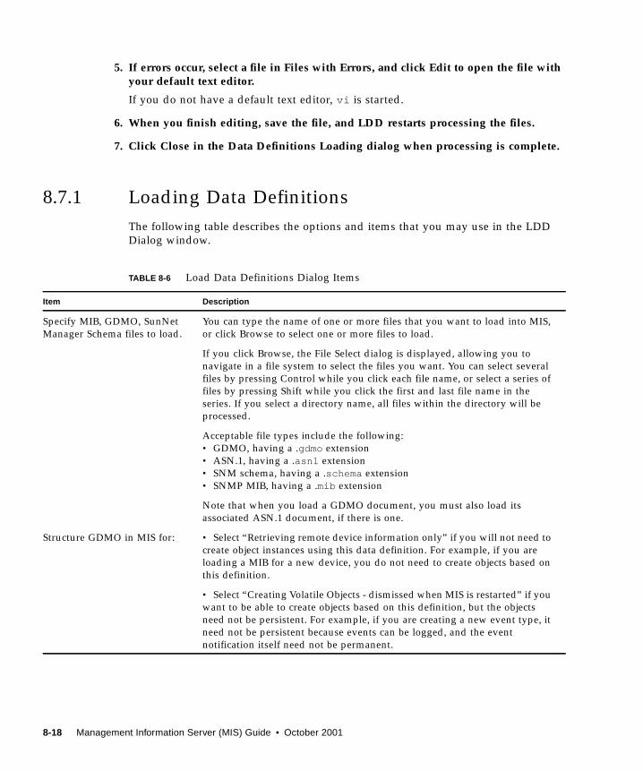
5. If errors occur, select a file in Files with Errors, and click Edit to open the file withyour default text editor.
If you do not have a default text editor, vi is started.
6. When you finish editing, save the file, and LDD restarts processing the files.
7. Click Close in the Data Definitions Loading dialog when processing is complete.
8.7.1 Loading Data Definitions
The following table describes the options and items that you may use in the LDD
Dialog window.
TABLE 8-6 Load Data Definitions Dialog Items
Item Description
Specify MIB, GDMO, SunNet
Manager Schema files to load.
You can type the name of one or more files that you want to load into MIS,
or click Browse to select one or more files to load.
If you click Browse, the File Select dialog is displayed, allowing you to
navigate in a file system to select the files you want. You can select several
files by pressing Control while you click each file name, or select a series of
files by pressing Shift while you click the first and last file name in the
series. If you select a directory name, all files within the directory will be
processed.
Acceptable file types include the following:
• GDMO, having a .gdmo extension
• ASN.1, having a .asn1 extension
• SNM schema, having a .schema extension
• SNMP MIB, having a .mib extension
Note that when you load a GDMO document, you must also load its
associated ASN.1 document, if there is one.
Structure GDMO in MIS for: • Select “Retrieving remote device information only” if you will not need to
create object instances using this data definition. For example, if you are
loading a MIB for a new device, you do not need to create objects based on
this definition.
• Select “Creating Volatile Objects - dismissed when MIS is restarted” if you
want to be able to create objects based on this definition, but the objects
need not be persistent. For example, if you are creating a new event type, it
need not be persistent because events can be logged, and the event
notification itself need not be permanent.
8-18 Management Information Server (MIS) Guide • October 2001

• Select “Creating Persistent Objects - persist when MIS is restarted” if you
want objects created based on this definition to remain after MIS is
restarted. For example, if you are adding a new user class, you would want
objects based on this class to be persistent.
Load Click Load when you have specified the files for the data you want to add
to MIS, and specified how you want the data structured. Load Data
Definitions will take the appropriate actions to import the data into MIS.
Depending on the type of files you are working with, and what GDMO
structuring option you chose, the Activity Log may display output from any
of the following programs:
• em_asn1• em_gdmo• em_compose_oc• em_compose_poc• em_compose_all• em_load_name_bindings• em_cmib2gdmo• em_snm2gdmoThese compilers are described in Appendix B.
Activity Log The Activity Log window shows the output from the translators and
compilers that LDD runs.
Files with Errors Select a file name from the list of files with errors so you can edit it to
correct the errors.
Edit Click Edit to start your default text editor and open the file you selected in
Files with Errors. If you do not have a default editor defined with the
EDITOR environment variable, the editor used is vi
TABLE 8-6 Load Data Definitions Dialog Items (Continued)
Item Description
Chapter 8 Adding New Data Definitions 8-19

8-20 Management Information Server (MIS) Guide • October 2001
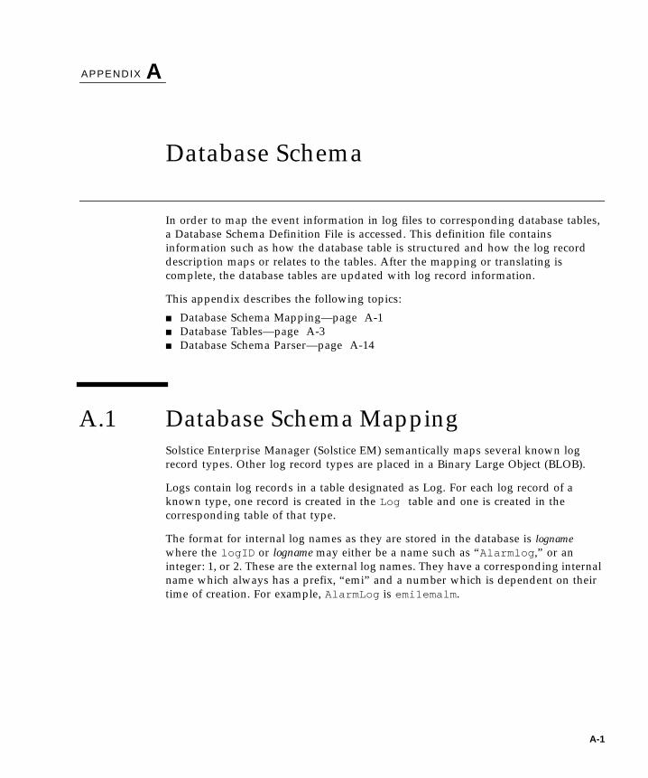
APPENDIX A
Database Schema
In order to map the event information in log files to corresponding database tables,
a Database Schema Definition File is accessed. This definition file contains
information such as how the database table is structured and how the log record
description maps or relates to the tables. After the mapping or translating is
complete, the database tables are updated with log record information.
This appendix describes the following topics:
■ Database Schema Mapping—page A-1
■ Database Tables—page A-3
■ Database Schema Parser—page A-14
A.1 Database Schema MappingSolstice Enterprise Manager (Solstice EM) semantically maps several known log
record types. Other log record types are placed in a Binary Large Object (BLOB).
Logs contain log records in a table designated as Log. For each log record of a
known type, one record is created in the Log table and one is created in the
corresponding table of that type.
The format for internal log names as they are stored in the database is lognamewhere the logID or logname may either be a name such as “Alarmlog ,” or an
integer: 1, or 2. These are the external log names. They have a corresponding internal
name which always has a prefix, “emi” and a number which is dependent on their
time of creation. For example, AlarmLog is emi1emalm .
A-1

The naming convention used for any given log uses the format (refer also to the
following table): internal logid abbreviated log record type.
For example, if the internal name of the alarm log is Alarm, then alarm records are
stored in a table called emsalarmemalm .
The following table contains a list of all the log records types supported by
Solstice EM.
TABLE A-1 Log Record Naming
Naming Tag Examples of Specific Names
internal emi
log name alarmlog, 0+, 1, 2
log record type emalrm or obcre, etc.
TABLE A-2 Log Record Types
Log Record Type
Alarm Log emi1emalm
emi1obcre
emi1obdel
Test Log emi2emalm
emi1obcre
emi2obdel
emi2_blob
A-2 Management Information Server (MIS) Guide • October 2001

A.2 Database TablesThe following table lists the tables specified in the configuration file that correspond
to log record types and contain miscellaneous system information.
Tables A-4 through A-17 show additional database tables that are supported. These
include:
■ emi1avchr—page A-4■ emi1blob—page A-4■ emi1emalm—page A-4■ emi1emint—page A-6■ emi1nrvct—page A-7■ emi1obcre—page A-9■ emi1obdel—page A-9■ emi1relch—page A-10■ emi1secur—page A-10■ emi1stchg—page A-11■ log—page A-12■ operator_actions—page A-12■ rpc_agents—page A-13■ snmp_agents—page A-13
TABLE A-3 Table Name Representations for Log Record Types
Table Name Log Record Type
objectCreationRecord emi1obcre
objectDeletionRecord emi1obdel
emAlarmRecord emi1emalm
attributeValueChangeRecord emi1avchr
relationshipChangeRecord emi1elchg
emInternetAlarmRecord emi1emint
nerveCenterAlarmRecord emi1nrvct
not applicable; used for user defined and unmapped log records emi_gblob
not applicable; used for security alarm record emi1secur
not applicable; used for state change record emi1stchg
Appendix A Database Schema A-3
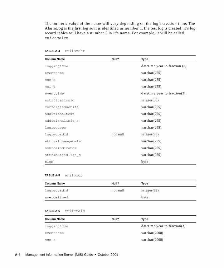
The numeric value of the name will vary depending on the log’s creation time. The
AlarmLog is the first log so it is identified as number 1. If a test log is created, it’s log
record tables will have a number 2 in it’s name. For example, it will be called
emi2emalrm .
TABLE A-4 emi1avchr
Column Name Null? Type
loggingtime datetime year to fraction (3)
eventname varchar(255)
moc_s varchar(255)
moi_s varchar(255)
eventtime datetime year to fraction(3)
notificationid integer(38)
correlatednotifs varchar(255)
additionaltext varchar(255)
additionalinfo_s varchar(255)
logrectype varchar(255)
logrecordid not null integer(38)
attrvalchangedefs varchar(255)
sourceindicator varchar(255)
attributeidlist_s varchar(255)
blob byte
TABLE A-5 emi1blob
Column Name Null? Type
logrecordid not null integer(38)
userdefined byte
TABLE A-6 emi1emalm
Column Name Null? Type
loggingtime datetime year to fraction(3)
eventname varchar(2000)
moc_s varchar(2000)
A-4 Management Information Server (MIS) Guide • October 2001

moi_s varchar(2000)
eventtime datetime year to fraction(3)
notificationid integer(38)
correlatednotifs varchar(255)
additionaltext varchar(255)
additionalInfo_s varchar(2000)
logrectype varchar(2000)
logrecordid not null integer(38)
probablecause_s varchar(2000)
probablecauseoid varchar(20)
perceivedseverity varchar(14,0)
specificproblems varchar(2000)
backedupstatus varchar(13,0)
backupobject varchar(2000)
trendindication varchar(11,0)
thresholdinfo_s varchar(255)
statechangedef_s varchar(2000)
monitoredattribs varchar(2000)
proposedrpracts varchar(255)
ackstate varchar(8,0)
acktime datetime year to fraction(3)
ackoperator varchar(16,0)
acktext varchar(257)
clearstate varchar(10,0)
cleartime datetime year to fraction(3)
clearoperator varchar(16,0)
cleartext varchar(257)
displaystate varchar(12,0)
displaytime datetime year to fraction(3)
TABLE A-6 emi1emalm (Continued)
Column Name Null? Type
Appendix A Database Schema A-5

displayoperator varchar(16,0)
displaytext varchar(257)
blob byte
TABLE A-7 emi1emint
Column Name Null? Type
loggingtime datetime year to fraction(3)
eventname varchar(255)
moc_s varchar(255)
moi_s varchar(255)
eventtime datetime year to fraction(3)
notificationid integer
correlatednotifs varchar(255)
additionaltext varchar(255)
additionalinfo_s varchar(255)
logrectype varchar(255)
logrecordid not null integer
probablecause_s varchar(255)
perceivedseverity varchar(14,0)
attributeidlist_s varchar(255)
objectinstancelsts varchar(255)
snmpvarbindlist_s varchar(255)
internettrapinfo_s varchar(255)
transport_domain_s varchar(255)
accesscontrolinfos varchar(255)
specificproblems_s varchar(2000)
backedupstatus varchar(13)
backupobject varchar(2000)
trendindication varchar(11)
thresholdinfo_s varchar(2000)
TABLE A-6 emi1emalm (Continued)
Column Name Null? Type
A-6 Management Information Server (MIS) Guide • October 2001

statechangedef_s varchar(2000)
monitoredattribs varchar(2000)
proposedrpracts varchar(2000)
ackstate varchar(8,0)
acktime datetime year to fraction(3)
ackoperator varchar(16,0)
acktext varchar(257)
clearstate varchar(10,0)
cleartime datetime year to fraction(3)
clearoperator varchar(16,0)
cleartext varchar(257)
displaystate varchar(12,0)
displaytime datetime year to fraction(3)
displayoperator varchar(16,0)
displaytext varchar(257)
blob byte
TABLE A-8 emi1nrvct
Column Name Null? Type
loggingtime datetime year to fraction(3)
eventname varchar(2000)
moc_s varchar(2000)
moi_s varchar(2000)
eventtime datetime year to fraction(3)
notificationid integer
correlatednotifs varchar(2000)
additionaltext varchar(2000)
additionalinfo_s varchar(2000)
logrectype varchar(2000)
logrecordid not null integer
TABLE A-7 emi1emint (Continued)
Column Name Null? Type
Appendix A Database Schema A-7
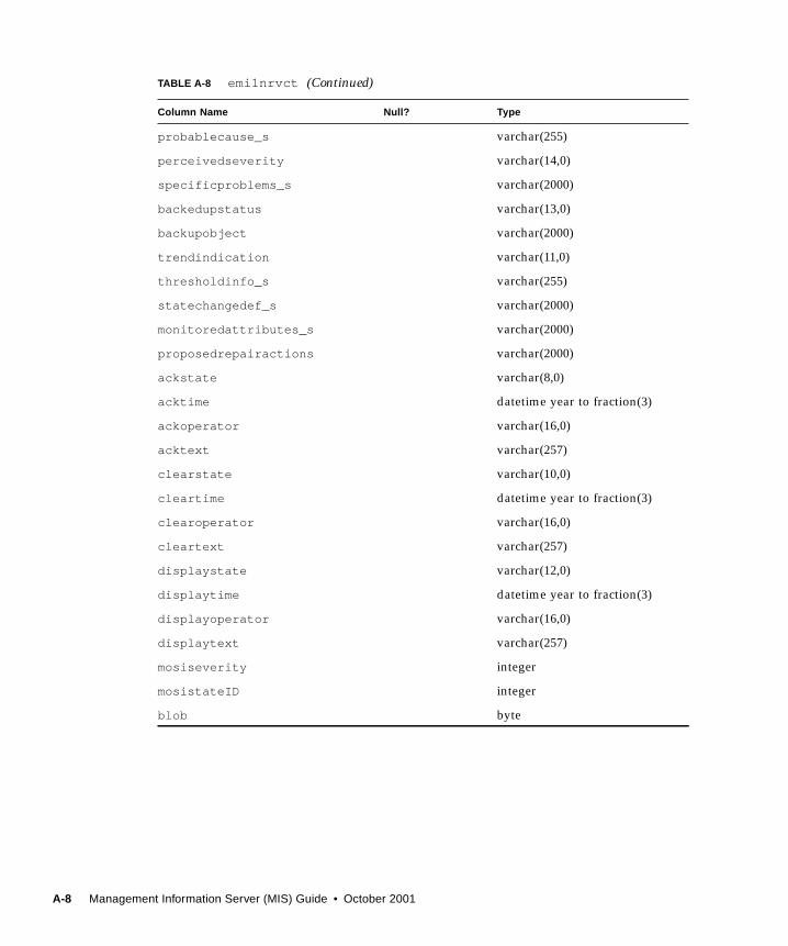
probablecause_s varchar(255)
perceivedseverity varchar(14,0)
specificproblems_s varchar(2000)
backedupstatus varchar(13,0)
backupobject varchar(2000)
trendindication varchar(11,0)
thresholdinfo_s varchar(255)
statechangedef_s varchar(2000)
monitoredattributes_s varchar(2000)
proposedrepairactions varchar(2000)
ackstate varchar(8,0)
acktime datetime year to fraction(3)
ackoperator varchar(16,0)
acktext varchar(257)
clearstate varchar(10,0)
cleartime datetime year to fraction(3)
clearoperator varchar(16,0)
cleartext varchar(257)
displaystate varchar(12,0)
displaytime datetime year to fraction(3)
displayoperator varchar(16,0)
displaytext varchar(257)
mosiseverity integer
mosistateID integer
blob byte
TABLE A-8 emi1nrvct (Continued)
Column Name Null? Type
A-8 Management Information Server (MIS) Guide • October 2001

TABLE A-9 emi1obcre
Column Name Null? Type
loggingtime datetime year to fraction(3)
eventname varchar(255)
moc_s varchar(255)
moi_s varchar(255)
eventtime datetime year to fraction(3)
notificationid integer
correlatednotifs varchar(255)
additionaltext varchar(255)
additionalinfo_s varchar(255)
logrectype varchar(255)
logrecordid not null integer
sourceindicator varchar(20,0)
attributeidlist_s varchar(255)
blob byte
TABLE A-10 emi1obdel
Column Name Null? Type
loggingtime datetime year to fraction(3)
eventname varchar(255)
moc_s varchar(255)
moi_s varchar(255)
eventtime datetime year to fraction(3)
notificationid datetime year to fraction(3)
correlatednotifs varchar(255)
additionaltext varchar(255)
additionalinfo_s varchar(255)
logrectype varchar(255)
logrecordid not null integer
Appendix A Database Schema A-9

sourceindicator varchar(20,0)
attributeidlist_s varchar(255)
blob byte
TABLE A-11 emi1relch
Column Name Null? Type
loggingtime datetime year to fraction(3)
eventname varchar(255)
moc_s varchar(255)
moi_s varchar(255)
eventtime datetime year to fraction(3)
notificationid integer
correlatednotifs varchar(255)
additionaltext varchar(255)
additionalinfo_s varchar(255)
logrectype varchar(255)
logrecordid not null integer
relationchangedefs varchar(255)
sourceindicator varchar(20)
attributeidlist_s varchar(255)
blob byte
TABLE A-12 emi1secur
Column Name Null? Type
loggingtime datetime year to fraction(3)
eventname varchar(255)
moc_s varchar(255)
moi_s varchar(255)
eventtime datetime year to fraction(3)
TABLE A-10 emi1obdel (Continued)
Column Name Null? Type
A-10 Management Information Server (MIS) Guide • October 2001

notificationid integer(38)
correlatednotifs varchar(255)
additionaltext varchar(255)
additionalinfo_s varchar(255)
logrecyype varchar(255)
logrecordid not null integer(38)
securityalarmcauses varchar(255)
securityalmseverty varchar(255)
securityalmdtectrs varchar(14,0)
serviceuser_s varchar(255)
serviceprovider_s varchar(255)
blob byte
TABLE A-13 emi1stchg
Column Name Null? Type
loggingtime datetime year to fraction(3)
eventname varchar(255)
moc_s varchar(255)
moi_s varchar(255)
eventtime datetime year to fraction(3)
notificationid integer
correlatednotifs varchar(255)
additionaltext varchar(255)
additionainfo_s varchar(255)
logrectype varchar(255)
logrecordid not null integer(38)
statechangedef_s varchar(255)
sourceindicator varchar(20,0)
attributeidlist_s varchar(255)
blob byte
TABLE A-12 emi1secur (Continued)
Column Name Null? Type
Appendix A Database Schema A-11

TABLE A-14 log
Column Name Null? Type
logid not null varchar(255)
emlogid integer
logidtype varchar(8,0)
lastlogrecId integer
administrativestate varchar(13,0)
operationalst varchar(10,0)
availabilityst varchar(13,0)
logfullaction varchar(128,0)
maxlogsize integer
currentlogsize integer
numberofrecords integer
starttime datetime year to fraction(3)
stoptime datetime year to fraction(3)
intervalsofdays varchar(255)
weekmask_s varchar(255)
externalscheduler varchar(255)
discrimconstruct byte
TABLE A-15 operator_actions
Column Name Null? Type
logfdn varchar(1000)
logrecordid integer
operatorname varchar(16,0)
actionname varchar(30,0)
actiontime date
A-12 Management Information Server (MIS) Guide • October 2001

attributename varchar(20,0)
oldattributevalue varchar(25)
newattributevalue varchar(25)
TABLE A-16 rpc_agents
Column Name Null? Type
agent_info varchar(1024)
agent_tag integer(38)
agent_id_s varchar(1024)
agent_id_b varchar(1024)
agent_set varchar(2000)
dns_blob varchar(2048)
mpa_addr_s varchar(1024)
mpa_addr_i integer
mpa_addr_n smallint
get_commty varchar(1024)
set_commty varchar(1024)
adminstate varchar(64)
opstate varchar(64)
TABLE A-17 snmp_agents
Column Name Null? Type
title_str varchar(255)
title_null smallint
agent_name varchar(254,0)
mpa_addr_s varchar(255)
mpa_addr_i integer
TABLE A-15 operator_actions (Continued)
Column Name Null? Type
Appendix A Database Schema A-13

A.3 Database Schema ParserLog records are derived from eventLog . Additionally, new types of log records can
be defined by deriving from the base eventLog and adding new attributes. This
allows the database structure to be configured. Therefore, a mechanism exists that
facilitates dynamic addition to the known types of event records by using a
description language to define all record types and their structure. An initialization
file containing these descriptions is processed each time the daemon is started; it
must contain a definition of the base record and all other possible records. If it is
determined that database tables corresponding to each record type do not already
exist, then they are created; it is possible to set a configuration option that will cause
the system to fail instead.
Along with the basic data types (such as int and string ), the more complex SETOFdata type is supported. The SETOFattribute type is a list. If N elements are present
in one instance of such an attribute type, then N elements are created in a table,
emSetof , which corresponds to the list structure. (This table is defined in a similar
fashion as a record.) On encountering a data element set, a record is written to the
emSetof table in addition to the actual data being written to its corresponding table.
mpa_addr_n smallint
trans_addr varchar(255)
get_commty varcharvarchar(255)
set_commty varchar(255)
mgmt_prtcl varchar(255)
mibs_str char (2000)
access_enf varchar(64,0)
access_mch varchar(64,0)
adminstate varchar(64,0)
opstate varchar(64,0)
TABLE A-17 snmp_agents (Continued)
Column Name Null? Type
A-14 Management Information Server (MIS) Guide • October 2001

APPENDIX B
Management Information Tree(MIT)
This appendix describes the following topics:
■ Section B.1 “Management Information Tree Objects” on page B-1
■ Section B.2 “Compilers” on page B-3
■ Section B.3 “Command Line Syntax for em_gdmo” on page B-8
■ Section B.4 “The Concise MIB Compiler” on page B-10
■ Section B.5 “The Schema Compiler” on page B-15
■ Section B.6 “Invoking the Compilers” on page B-17
Note – It is assumed that you installed Solstice EM in the default directory
/opt/SUNWconn/em . If you installed the product in a different directory, replace all
/opt/SUNWconn/em instances in this chapter with the appropriate directory path.
Compilers provide a way for you to add new managed object definitions to the MIS.
If your application refers only to object classes already known to the Solstice
Enterprise Manager (Solstice EM) MIS, you will not need to use these compilers.
However, if you plan to add new managed objects to MIS, read this chapter for
instructions.
B.1 Management Information Tree ObjectsEvery object known to MIS is represented in the MIT. The objects in the MIT include
network devices such as routers and hosts, virtual objects such as queues, filters, and
events, and objects that MIS itself or applications create. A single global MIT
provides a single naming scheme for all data. The MIT is constructed according to a
standard provided by OMNIPoint 1.
B-1

B.1.1 Object Descriptions
A description of every object known to MIS is stored in the MDR. The data in the
descriptions encompasses everything from the syntax required to refer to an
attribute, to the composition of an object package. The MIS then makes this data
available to its clients.
For every managed object known to MIS, there also must be the following
information:
■ The class to which the object belongs.
■ The specifics of the instance of that class, such as a list of attributes, the syntax of
each attribute, and the name bindings, which give the object’s position within the
MIT.
The definitions for managed objects are contained in ASN.1 and GDMO documents.
These are found in the following default directories, respectively:
■ /opt/SUNWconn/bin/etc/asn1■ /opt/SUNWconn/bin/etc/gdmo
These documents are normally compiled and installed into the MDR when you
install Solstice EM, or when you run the command em_services -reload
For more information about the em_services command, see Chapter 2.
Note – There is one GDMO document associated with a particular managed object.
The document names are usually composed of the name of the managed object class
followed by the suffix .asn1 or .gdmo
B.1.2 Adding a New Managed Object to the MDR
If you want to add a new definition for a managed object to the MDR, you must
create the appropriate ASN.1 and GDMO documents. You can use existing ASN.1
and GDMO documents as templates for your new documents, or you can write your
own from scratch. Once you have created these documents, you must compile the
definitions and add them to the MDR.
B-2 Management Information Server (MIS) Guide • October 2001

B.1.3 Compiling Definitions for the MDR
The following summarizes the processes handled by each compiler:
■ The ASN.1 Compiler (em_asn1)
This compiler processes a description of a managed object transfer syntax written
in ASN.1 type format. Such a description may be produced as output from the
Concise MIB compiler, from the Schema compiler, or can be supplied directly
from an ASN.1 document. See “The ASN.1 Compiler” on page 3, for details on
using this compiler.
■ The GDMO Compiler (em_gdmo)
This compiler processes a managed object description written in GDMO format.
Such a description may be produced as output from the Concise MIB compiler,
from the Schema compiler, or can be supplied directly from a GDMO document.
See “The GDMO Compiler” on page 5, for details on using this compiler.
■ The Concise MIB Compiler (em_cmib2gdmo)
This compiler translates an SNMP MIB into both GDMO and ASN.1 formats, thus
serving as a preprocessor for both the GDMO and ASN.1 compilers. See “The
Concise MIB Compiler” on page 10, for details.
■ The Schema Compiler (em_snm2gdmo)
You can use this compiler to translate SunNet Manager 2.2 or later schema files to
GDMO and ASN.1 format. This compiler serves as a preprocessor to the GDMO
compiler. Refer to Section B.5 “The Schema Compiler” on page B-15 for detailed
information on the Schema compiler.
B.2 CompilersThe following are descriptions of each compiler.
B.2.1 The ASN.1 Compiler
Use the ASN.1 compiler to compile ASN.1 descriptions of managed objects
contained in ASN.1 documents, into the MDR.
ASN.1 documents contain ASN.1 definitions written in ASN.1 format. A message
that uses ASN.1 encoding must include not only the encoded data, but also
information about the type of encoded information. A process that represents a
value with an ASN.1 encoding, or that extracts a value from an ASN.1 encoding,
Appendix B Management Information Tree (MIT) B-3

must be able to access the definition of the particular encoding employed. The
GDMO descriptions of new objects also make reference to ASN.1 descriptions for the
syntax of attributes defined within.
To provide effective access to the needed ASN.1 definitions, the Solstice EM MDR
keeps a set of files containing type definitions and encoding rules. When the
definitions of new objects make reference to new ASN.1 types, files containing the
new ASN.1 definitions must be included in the MIS ASN1directory. At start-up and
periodically thereafter, the Solstice EM MIS loads these ASN.1 type files into the
MDR.
Solstice EM provides ASN.1 documents for a variety of managed objects. These
documents are located in the directory /opt/SUNWconn/bin/etc/asn1 .
B.2.1.1 Compiling ASN.1 Documents
The ASN.1 compiler compiles the contents of ASN.1 documents into a format used
internally by MIS. Upon successful compilation, it places the output files into the
directory in which the compiler was invoked. You must then move or copy the
output file into the /var/opt/SUNWconn/em/usr/data/ASN1 MDR user
directory. Alternatively, you can use the -o parameter and specify this directory
when invoking the ASN.1 compiler from the command line.
▼ To Invoke the ANS.1 Compiler
● Type:
em_asn1 [-debug][-verbose][-output <output_dir>] file <file> [file] ...
The optional parameters for the em_asn1 command are described in the following
table.
TABLE B-1 Command Options for em_asn1
Option Description
-help Print list of options (with descriptions) for the em_asn1 command.
-verbose Specify verbose mode.
-output <dirname> Specify the directory into which the compiled files are to be written.
The directory will be created if it does not already exist.
-file <filename> Specify the name of the ASN.1 document to be compiled. Multiple
file names may be specified, delimited by a space.
-debug Specify debug mode.
B-4 Management Information Server (MIS) Guide • October 2001

For detailed information on using ASN.1 and the format of ASN.1 definitions, refer
to the following reference materials:
■ ISO 8824 Specification of Abstract Syntax Notation One (ASN.1)
■ ISO 8825 Specification of Basic Encoding Rules for Abstract Syntax Notation One(ASN.1)
B.2.2 The GDMO Compiler
You can use the GDMO compiler (em_gdmo) to compile new GDMO managed object
descriptions. To add them to the MDR, you must either restart MIS, or use the
-host hostname parameter. This enables MIS to recognize new classes of GDMO-
defined objects not previously known to it. For examples of this procedure, see
Chapter 8.
B.2.2.1 GDMO Updates
The GDMO compiler has been enhanced to be compliant with the 1995 amendments
to the ITU GDMO specification. (For information on the 1995 amendments to the
ITU GDMO specification, see the CCITT Recommendation X.722 and Amendments
1, 2, and 3.) This enhancement includes:
■ Support for the alias directive feature
Solstice EM’s GDMO compiler now supports both exporting and importing alias
directive entries in its GDMO files. The syntax of GDMO Alias directive is as
specified in Amendment 2 of X.722.
■ The addition of a Global Documents Aliases Names Database
To support the alias feature, Solstice EM now has Global Documents Aliases
Names Database (GDANDB). This database is contained in a flat file found at
/var/opt/SUNWComm/em/date/MDR/EM_ALIAS_REF .
During a compilation, the GDMO compiler adds entries to this database upon
detecting an “exporting” Alias directive. Entries to this database are checked for
uniqueness to avoid duplication. To avoid possible corruption to the database
entries due to multiple concurrent compiler users, only one user is allowed to
update the database at a time. Another user will be blocked from updating until
the lock is removed.
■ Integration of the SUNWgdmod v2.0 packages into Solstice EM and the Sun TMN
product set.
SUNWgdmod v2.0 is integrated into Solstice EM so that both Solstice EM and the
Sun TMN product set support the same set of ITU/CCITT standard GDMO MIB
files.
Appendix B Management Information Tree (MIT) B-5

■ The OID for X.227 document has been changed to:
■ ACSE-1 {joint-iso-itu-t association-control (2) modules (0)apdus (0) version1 (1) }
■ Support for the following new properties and directives:
■ SET-BY-CREATEproperty (as specified in Amendment 1 of X.722)
■ NO-MODIFYproperty (as specified in Amendment 2 of X.722)
■ GDMO.Document and GDMO-End-Document directives (as specified by
Amendment 2 OF x.722)
■ GDMO.Version directive (as specified in Amendment 2 of X.722)
■ Support for Document Override feature
A new directive extension by Sun GDMO Override is added to enable overriding the
document label. If an Override directive is stated for a particular document, the
document label, if and when completed, will be replaced with the overriding label.
The syntax of Override directive is <GDMO.Override “<old label> ” “<newlabel >”. The typical path name of the override directives is
opt/SUNWcomm/em/etc/gdmo/em_alias_ref.gdmo
B.2.2.2 GDMO Compiler Input
The GDMO compiler takes as its input one or more object class descriptions written
in the standard GDMO format. The input must be provided in ASCII text files. A
single file may contain several descriptions; the required format for a description
clearly delimits the beginning and end of each. You may write a single description so
that it spans several files, but this is not recommended.
The format of a GDMO description is described in the ISO/IEC 10165-4 specification
Information Technology - Structure of Management Information - Part 4: Guidelines for theDefinition of Managed Objects. This refernce resource publication includes templates;
that is, sample descriptions of various types of managed objects. These templates
may serve as models for the description of specific objects of the same general type
but with differing particulars.
The GDMO compiler follows the required format very closely and is unforgiving of
deviations.
The Solstice EM product provides GDMO documents in the $EM_HOME/etc/gdmodirectory. You can use these managed object descriptions as is, or you can create
your own. If you are creating new managed object definitions, note that GDMO
documents are generally given mnemonic names followed by a .gdmo extension.
When the GDMO compiler is used on these files, it produces one or more output
files depending on the content of the documents.
B-6 Management Information Server (MIS) Guide • October 2001

Solstice EM provides the user MDR directory /var/opt/SUNWconn/em/usr/data/MDR in which you can store your private compiled GDMO documents. When
MIS is started, it looks for compiled documents in both this directory and the
directory /var/opt/SUNWconn/em/data/MDR , and loads any appropriate
documents that it finds. For the documents to be loaded into the MDR, they must be
in one of these two directories. You can compile the documents in any directory and
then manually copy or move then over, or you can specify a directory using the
-output <output_dir> parameter (see “Command Line Syntax for em_gdmo” on
page 8).
B.2.2.3 Managing Related GDMO Documents
For parsing purposes, all GDMO definitions and documents used by a GDMO
document should be in the same file. This ensures proper validation across
document boundaries. Parsing GDMO documents as separate files is permissible,
but does not provide cross-validation between files.
Consider an example where Document A calls out an attribute operationalState and
states it is defined in Document B. The actual syntax of operationalState cannot be
validated unless Document B is in the same file.
If Document B is a different file, during parsing of Document A, the parser assumes
that Document B will be found and will contain what is needed. If in Document B
the attribute name is misspelled (for example, OperationalState rather than
operationalState), the parser cannot validate Document B and therefore notes a
warning. A warning is not fatal; it would be reported even if Document B were
perfect. Parsing then continues.
You may still receive a “parsing complete” message when the information is loaded
into the MDR. You would see no errors for Document B. Later, the fault will manifest
as a “no-such-attribute” error when an attempt is made to instantiate an object
whose definition contains the incorrect syntax.
This may also occur when an attempt is made to display information retrieved from
a remote object that uses the invalidated syntax.
B.2.2.4 GDMO Compiler Output
When the GDMO compiler runs in compile (non-parsing) mode, it reads the source
files, compiles them, and passes the compiled description—via the PMI—to a
running Solstice EM MIS. The portions of the description dealing with object classes,
packages, attributes, and name bindings are compiled and stored in the MDR.
Appendix B Management Information Tree (MIT) B-7

The output files are written to the directory in which the compiler was invoked. You
must then copy or move the output files to the directory /var/opt/SUNWconn/em/usr/data/MDR . Alternatively, you can specify this directory in conjunction with the
-output <output_dir> parameter when you invoke the GDMO compiler.
Note – If you invoke the GDMO compiler without the -host hostname parameter,
MIS must be restarted in order for the GDMO data to be loaded into the MDR.
Each output file is assigned a name derived from the source document, except a
space character is mapped to an underscore character, and a slash (/) character is
mapped to a percent character.
Each output file must start with a header line. If you invoke the GDMO compiler
with the -header <header_string> parameter, the specified string is used as the
first line of the output file. If you omit this parameter, the following default header
is used:
B.3 Command Line Syntax for em_gdmo
▼ To Invoke the GDMO Compiler
● Type:
em_gdmo [options] -file <file> [file] ...
The -file <file> parameter is used to specify the input file(s). The optional
parameters for the em_gdmocommand are described in the following table.
@(#) Created by <user> at <date>
TABLE B-2 Command Line Options for em_gdmo
Option Description
-debug Displays the MIS debugging information.
-help Prints list of options (with descriptions) for the em_gdmocommand.
-file <file> Specifies the names of the files to be parsed.
B-8 Management Information Server (MIS) Guide • October 2001

The GDMO compiler functions in two modes of operation:
■ Parse-only
■ Parse-and-compile
B.3.1 Parse-only Operation
Invoke the GDMO compiler as follows so that it uses a grammar parser to verify
conformance to syntactic rules:
em_gdmo -parse -file <file>
An error detected by the GDMO compiler during parsing generates a message
stating the name of the file being parsed, and the line number where the error was
encountered.
B.3.2 Parse-and-Compile Operation
Once the input files can be parsed without error, you can run the compiler in the
parse-and-compile mode to store the parsed and compiled definitions in the MDR
directory, then restart MIS to load the definitions.
- header <string> Specify the header string.
- host <server> Specifiesy the name of an MIS server. The compiled
definitions are loaded into the MDR.
-output <output_dir> Specifies the directory into which the compiled files are to be
written.
-parse Specifies parse-only operation.
-verbose Specifies verbose mode.
-version Displays the supported GDMO Standards version.
- file <file> Specifies the names of the files to be parsed.
TABLE B-2 Command Line Options for em_gdmo (Continued)
Option Description
Appendix B Management Information Tree (MIT) B-9
▼ To Run the Compiler in Parse-and-Compile
Mode
1. Invoke em_gdmoas follows:
em_gdmo -output /var/opt/SUNWconn/em/usr/data/MDR -file <file>
2. You then must run em_services to load the definitions into the MDR.Alternatively, you can load the definitions into the MDR directly:
em_gdmo -host <hostname> -file <file>
Caution – If the MIS does not have access to the required ASN.1 definitions, the
GDMO compiler will not receive an error. Consequently, the problem will not
become evident until later. When a process attempts to instantiate an object based on
the class description you supplied, or to display information retrieved from a remote
object that used your syntax, it is likely to receive a “no-such-attribute” error, or
some other related error.
To process the parsed and compiled input, MIS must refer to the ASN.1 documents
located in the $EM_HOME/etc/asn1 directory. You must be root to write to this
directory. The GDMO descriptions assume that these definitions are present. See
“Compiling ASN.1 Documents” on page 4, for more information about the
preparation, storage, and availability of ASN.1 files. ASN1 documents can be found
in the /var/opt/SUNWconn/em/usr/ASN1 directory.
B.4 The Concise MIB CompilerYou can extend the Solstice EM MIS Management Information Tree (MIT) to
recognize new types of managed objects. When a new object description is specified
in a GDMO document, the description can be processed directly by the GDMO
compiler (described in Section B.2.2 “The GDMO Compiler” on page B-5. However,
when the object description is written in the Internet Concise MIB format, the
description must first be processed by the Concise MIB compiler.
The Concise MIB compiler (em_cmib2gdmo) takes MIBs and generates two files in
the appropriate formats for the GDMO and ASN.1 compilers. When the resulting
GDMO descriptions are parsed and compiled, they make use of ASN.1 descriptions
of their data types. The Concise MIB compiler generates a <type>.asn1 file as well
as a <type>.gdmo file, as illustrated in FIGURE B-1.
B-10 Management Information Server (MIS) Guide • October 2001

If the target files exist, they are overwritten. You would normally use the Concise
MIB compiler (em_cmib2gdmo) in conjunction with the GDMO compiler (em_gdmo)and the ASN.1 compiler (em_asn1) to take a vendor- specific Concise MIB, convert
it to GDMO and ASN.1 components, and incorporate further compiled versions of
these into the Solstice EM MIS. The Concise MIB compiler checks the source files to
ensure they conform to RFC 1212, and reports any errors that are discovered. The
GDMO and ASN.1 output files are produced even if incorrect or incomplete.
By default, em_cmib2gdmo imports the following OIDs from RFC 1155:
■ ISO■ ORG■ DOD■ Internet■ directory■ MGMT■ experimental■ private■ enterprises
This importation can be suppressed by using the -1155 option (refer to TABLE B-2).
Also, by default, the following types are built in (normally defined in RFC 1155):
■ NetworkAddress■ IpAddress■ Counter■ Gauge■ TimeTicks■ Opaque
The following are also built in (normally defined in RFC 1213):
■ OBJECT-TYPE■ DisplayString■ PhysAddress
Appendix B Management Information Tree (MIT) B-11

FIGURE B-1 The Concise MIB Compiler
B.4.1 Names of Input and Output Files
An input file for the GDMO compiler can have any name, but by convention, the
name should end with the extension .mib . The Concise MIB compiler generates two
output files for each input file. The output files have the same names as the input file
with the extension (if any) replaced by .gdmo and .asn1 , respectively.
▼ To Process Files Produced by the Concise MIB
Compiler
1. Use the ASN.1 compiler to process the type.asn1 file.
See “The ASN.1 Compiler” on page 3, for more information about the ASN.1
compiler.
2. Use the GDMO compiler to process the <filename>.gdmo file.
Refer to “The GDMO Compiler” on page 5, for more information about the GDMO
compiler and how to further process the <filename>.gdmo file for inclusion in MIS.
<type >.asn1file type
<type> .gdmofile
etc/MDR
etc/
ASN1
em_asn1compiler
em_cmib2gdmocompiler
em_gdmocompiler
InternetSNMP MIBfile
EM MIS
B-12 Management Information Server (MIS) Guide • October 2001

B.4.2 Command Line Syntax for em_cmib2gdmo
Following is the format of the Concise MIB compiler’s command line syntax.
The optional parameters for the em_cmib2gdmo command are described in the
following table.
hostname% em_cmib2gdmo [-b - d -1155 -h -l -m -p -r -t -v1 -v2 -w- autosuffix] <file>...
TABLE B-3 Optional Parameters for em_cmib2gdmo
Option Description
-b Instructs the compiler to include CMIP descriptions in GDMO
behavior clauses. Normally, a reference to the description of the
Concise MIB object is given the GDMO output. By specifying -b, the
description is copied to the Behavior clause of the GDMO managed
object class or attribute.
-d Displays debugging information during translation.
-1155 Instructs the compiler not to automatically include OIDs from RFC
1155. Normally, the following types from RFC 1155 are
automatically defined: ISO, ORG, DOD, Internet, Directory, MGMT,
experimental, private, and enterprise. This is necessary because the
translator must resolve OIDs to full numerical paths. Because most
MIBs use one or more of these OIDs without redefining them
(unless this option is specified), you need not specify rfc1155.asn1
on the command line.
-h Prints the usage message.
-l Instructs the compiler to generate only a GDMO output file and an
ASN.1 type file for the last specified Concise MIB file.
-m Writes trap mapping information to file < f >.
-p Do not generate parsible behavior for GDMO table entry MOCs.
-r Writes em-objop script for updating event logging list to file < f >.
-t Translator performs various checks to ensure that the Concise MIB
definition is complete.Translator performs various checks to ensure
that the Concise MIB definition is complete.
-v1/-v2 Compiles in SMI -v1 or SMI -v2 mode.
-autosuffix Allows the user to choose which suffix to use for
iimcAutoNameBiding without getting a duplicated definition.
Appendix B Management Information Tree (MIT) B-13

The -l option further instructs the compiler to generate only a GDMO output file
and an ASN.1 type file for the last specified Concise MIB file. This is useful if a MIB
imports information from another MIB, but you wish to translate only the MIB with
the dependency. For example, if the (RMON) MIB rfc1271 imports OIDs from
rfc1213 (MIB-II), but you have no desire to translate rfc1213 , you can use the
following command:
Only the rfc1271.gdmo and rfc1271TYPE.asn1 output files are generated.
For detailed information about Concise MIBs and the format of Concise MIB
definitions, refer to the following reference materials:
■ RFC 1212, Concise MIB Definitions
■ RFC 1215, A Convention for Defining Traps for use with the SNMP
■ LaBarre, Lee (Ed), ISO/CCITT and Internet Management Coexistence (IIMC):Translation of Internet MIBs to ISO/CCITT GDMO MIBs, March 26, 1993
■ LaBarre, Lee (Ed), ISO/CCITT and Internet Management Coexistence (IIMC):Translation of Internet MIB-II (RFC1213) to ISO/CCITT GDMO MIB
■ ISO/CCITT SMI Guidelines for Definition of Managed Objects [ISO10165-4]
B.4.3 Diagnostics
The compiler is structured to recover from syntax errors. The type checker does not
affect the translation process, but simply produces messages if it finds type errors.
The GDMO output phase prints warnings for those OIDs that are not resolved. It
also prints the characters “???” in place of the unresolved OID in the GDMO output
file.
-w Several potential problems discovered during translation are not
serious enough to be considered errors, and are thus classified as
warnings.
-a Appends trap mapping information to the trap_maps file.
<file1> <file2> Specifies the names of the Concise MIB files to be compiled.
em_cmib2gdmo -l rfc1213.mib rfc1271.mib
TABLE B-3 Optional Parameters for em_cmib2gdmo (Continued)
Option Description
B-14 Management Information Server (MIS) Guide • October 2001

B.5 The Schema CompilerThe SunNet Manager (SNM) 2.x products use schema files to represent the managed
object classes available to the SNM database. You must use the Schema compiler
(em_snm2gdmo) as the first step in converting the SNM 2.2 or later schema files into
GDMO descriptions used in Solstice EM.
To translate an SNM 2.2 or later schema file, run the Schema compiler with the file to
be translated as an argument (<filename>). The output of the translation produces
two files:
■ A GDMO document with a name of the form <filename>.gdmo for non-agent
schemas, or <agent/proxy_name>.gdmo for SNM agent schemas.
■ An ASN.1 document with a name of the form <filename>.asn1 for non-agent
schemas, or <agent/proxy_name>.asn1 for SNM agent schemas.
These output files are created in the directory from which you invoke the Schema
compiler. Once you have created the output files, you must then pass them through
the GDMO compiler.
B.5.1 Command Line Syntax for em_snm2gdmo
▼ To Invoke the Schema Compiler
1. Type:
You must specify the filename of the schema file you want to translate, and any
unused <OID_branch> number for that file. This number is used to assign a unique
OID to every record type defined within the specified schema file. To determine
em_snm2gdmo <filename> <OID_branch>
Appendix B Management Information Tree (MIT) B-15

which OID branch numbers have not already been used, go to the directory where
the ASN.1 documents are stored (the default directory is $EM_HOME/etc/asn1 ),
then type the following command:
All files that are generated by the schema compiler will contain the line:
The OID branch numbers “0” and “1” are reserved:
■ “0” is reserved for SNM agent/proxy schemas, which can be found in
$SNM_HOME/agents.
■ “1” is reserved specifically for the schema file elements.schema .
To find out what other OID branch numbers have already been used, edit the files
listed as a result of the grep command shown above. The following code example
lists is the contents of the file cooptoolsschema.asn1
The OID branch number is the last integer before the } character in the lines
beginning with “Cooptoolsschema ”. The number 3 has been assigned to the
schema file cooptools.schema .
grep “em_snm2gdmo” *.asn1
-- This file was generated by em_snm2gdmo.
CODE EXAMPLE B-1 cooptoolsschema.asn1 file
-- This file was generated by em_snm2gdmo.-- The module name is used by the 2.x compatibility library.-- Do not edit this file by hand.CooptoolsschemaASN1 { iso(1) org(3) dod(6) internet(1) private(4)enterprise(1)
sun(42) products(2) management(2) em(2) rpc(12) 3 }DEFINITIONS ::= BEGINcooptoolsschemaREG OBJECT IDENTIFIER ::= { iso(1) org(3) dod(6)
internet(1) private(4) enterprise(1) sun(42)products(2) management(2) em(2) rpc(12) 3 }
ViewdotHoldingAreaData ::= SEQUENCE { name RpcCommonDef.String, contact RpcCommonDef.String, location RpcCommonDef.String, description RpcCommonDef.String, glyphusrState RpcCommonDef.Enumeration}END
B-16 Management Information Server (MIS) Guide • October 2001

Refer to the Solstice Site/SunNet/Domain Manager Application and Agent DevelopmentGuide for a description of the schema file format.
Diagnostics
The Schema compiler stops at the first occurrence of an error in the schema file. In
many cases it displays messages that aid in debugging, but does not do so in all
cases.
B.6 Invoking the CompilersThe following command line options may also be used for invoking the compilers.
▼ The em_asn1 Command
The em_asn1 command invokes the ASN.1 compiler, which is used to compile the
contents of ASN.1 documents into a format used internally by MIS.
B.6.1 To Invoke the ANS.1 Compiler
● Type:
The optional parameters for the em_asn1 command are described in TABLE B-1.
▼ The em_compose_all Command
The em_compose_all command takes a GDMO file as input, and:
■ Reads all the object classes and name bindings in the GDMO definition file.
■ Composes and loads the name bindings accordingly in MIS.
Prior to running this command, the GDMO file should have been loaded into the
MDR using the GDMO compiler em_gdmo.
em_asn1 [-verbose] [-output <output_dir>] <file>...
Appendix B Management Information Tree (MIT) B-17

Invoke the em_compose_all command from the command line as follows:
You must specify the name of a GDMO document.
▼ The em_compose_oc Command
The em_compose_oc command is used to instantiate a new object class with volatile
data storage. Volatile data storage means that if MIS is restarted (with the
em_services command but without the -i option), any object of the object class
which was composed with the em_compose_oc command will not be in MIS after it
is restarted.
Before running this command, the Managed Object Class should have been loaded
into the MDR using the GDMO compiler em_gdmoand the ASN.1 compiler
em_asn1 .
B.6.2 To Invoke the em_compose_oc Command
● Type:
The arguments for the em_compose_oc command are one or more object classes
from the GDMO file.
▼ The em_compose_poc Command
The em_compose_poc command is used to instantiate a new object class with
persistent data storage. Persistent data storage means that if MIS is restarted (with
the em_services command, but without the -i option), any object of the object
class which was composed with the em_compose_oc command will remain in MIS
after it is restarted.
Note – If MIS is restarted using em_services -i , then all persistent storage is
lost.
em_compose_all <filename>
em_compose_oc <object_class> ...
B-18 Management Information Server (MIS) Guide • October 2001

Before running this command, the Managed Object Class should have been loaded
into the MDR using the GDMO compiler em_gdmoand the ASN.1 compiler
em_asn1 .
▼ To Invoke the em_compose_poc Command
● Type:
The arguments for the em_compose_poc command are one or more object classes
from the GDMO file.
B.6.3 The em_cmib2gdmo Command
The em_cmib2gdmo command invokes the Concise MIB compiler, which is used to
translate a managed object description written in the Concise MIB format into both
GDMO and ASN.1 formats, thus serving as a preprocessor for both the GDMO and
ASN.1 compilers.
▼ To Invoke the Concise MIB Compiler
● Type:
The optional parameters for the em_cmib2gdmo command are described in
TABLE B-3.
B.6.4 The em_gdmoCommand
The em_gdmocommand invokes the GDMO compiler, which is used to extend the
capabilities of the Solstice EM MIS to deal with new classes of objects not previously
known to it. It does this by compiling GDMO descriptions of managed objects,
which are provided in GDMO documents.
em_compose_poc <object_class>
em_cmib2gdmo [options] <file>...
Appendix B Management Information Tree (MIT) B-19

▼ To Invoke the GDMO Compiler
● Type:
The -file <file> parameter is used to specify the input file(s). The optional
parameters for the em_gdmocommand are described in TABLE B-2.
The GDMO compiler functions in two modes of operation:
■ Parse-only
■ Parse-and-compile
B.6.5 The em_load_name_bindings Command
The em_load_name_bindings command loads the name bindings, which tell MIS
where the object is in the MIT. Prior to running this command:
■ The GDMO definitions should be loaded into the MDR using the GDMO
compiler em_gdmo.
■ The ASN.1 definitions should be loaded into MDR using the ASN.1 compiler
em_asn1 .
■ The object classes used in the name binding should have been composed using
em_compose_oc or em_compose_poc .
▼ To Invoke em_load_name_bindings
● Type:
The command line arguments for the em_load_name_bindings command are one
or more name bindings from the GDMO file.
B.6.6 The em_snm2gdmoCommand
The em_snm2gdmocommand invokes the Schema compiler, which is used to
translate SNM 2.2 or later schema files into GDMO descriptions used in Solstice EM.
em_gdmo [options] -file <file>...
em_load_name_bindings <name_binding> ...
B-20 Management Information Server (MIS) Guide • October 2001

▼ To Invoke the Schema Compiler
● Type:
The OID_branch parameter is any unused OID branch number for the specified
schema file.
This number is used to assign a unique OID to every record type defined within the
specified schema file. “0” and “1” are the only OID branch numbers that are already
reserved:
■ “0” is reserved for SNM agent/proxy schemas, which can be found in
$SNM_HOME/agents.
■ “1” is reserved specifically for the schema file elements.schema .
B.6.7 The em_topo_args Command
The command em_topo_args is used to pass arguments to applications that are
launched from the Object Menu of a device. For example:
In this example, serviceProvider is an attribute added to the topoNodeUserData
of a device type and so em_topo_args can be used to extract its value.
The em_topo_args command was written for backwards compatibility, although it
can be used for non bc applications. The % is from SNM. % in SNM is used to pass
an element type (glyph) schema attribute to the command line.
There are also some limitations on what you can pass on to an application. If the
topoNodeUserData type is a SET OF xxx, it will not work since topoargs does not
have a way to pull out individual members of a SET. It does work for SEQ.
em_snm2gdmo <filename> <OID_branch>
$EM_HOME/bin/em_topo_args EM_UNIQUE_ID “/bin/echo%serviceProvider > /tmp/test2”
Appendix B Management Information Tree (MIT) B-21

B-22 Management Information Server (MIS) Guide • October 2001
Index
AAbstract Syntax Notation One. See ASN.1
accessing a remote MIS, 3-1
activity log, 8-3, 8-17
AETitle
data storage, 1-9
agent, 1-6, 5-3
alarm, 6-7
log, 1-19
service module, 1-19
severity, 1-19
alarm events
acknowledged and cleared, 6-7
logged, 6-7
recognized and displayed, 6-7
applications, 1-5
ASN.1, 2-5, B-3
compiler, B-1, B-3, B-12
definition, B-3
descriptions, B-10
document, B-4, B-15
em_asn1 compiler, B-18
em_asn1 compiler , B-20
format, B-3
sample definition file, 8-9
associated agent objects, 5-8
Attribute Value Assertion. See AVA
attributes, managed object class, 8-6
attributeValueChange, 6-7
AVA, 1-16
Bbackup and restore, 5-1
backup, system crash, 5-3
big picture, 1-3
Binary Large Object. See BLOB
BLOB, A-1
Ccannot recover, 2-2
captured events, 6-2
change message, 1-10
CMIP
agent, 4-4
agents DNs, 4-5
autoregistration, 4-4
description, B-13
entity name, 4-5
MO DN, 4-5
MPA addresses, 4-5
presentation address, 4-5
starting, 4-2
CMIP/OSI, 1-12
coded logID, 6-17
command
copying network view and agent data, 5-5
em_asn1 , B-17
em_cmib2gdmo , B-19
em_compose_all , B-17
em_compose_oc , B-18
em_compose_poc , B-18
em_gdmo, B-19
em_imex , 5-12
Index-1

em_load_name_bindings , B-20
em_mismgr , 3-7
em_snm2gdmo, B-20
em_topo_args , B-21
emdb, 7-2
export network view data, 5-11
command line
restoring, 5-4
Common Management Protocol. See CMIP
communicationsAlarm, 3-11
mapped to log record type, 6-7
compiled GDMO files, location, 8-10
compilers, 1-20
components, 1-7
concise MIB compiler
command line options, B-13
convert to ASN.1 format, B-11
convert to GDMO format, B-11
description, B-10
em_cmib2gdmo , B-3, B-10, B-12
files generated, B-10
output files, B-12
syntax errors, B-14
configuration file, 4-3
configuring a toponode, 4-4
connection
manager, 3-11
convert legacy data, 5-12
copying network views and agent data, 5-5
corrupt data, 5-2
Ddaemons, 1-21
damaged database, 5-3
database
backup/restore tool, 5-2
delete data, 2-5
query, 7-1, 7-2
recreate, 2-4
schema mapping, 6-17, A-1
schema parser, 6-25, A-14
table, 6-18, A-3
emi1avchr , A-4
default
alarm types, 6-7
installation directory, B-1
port number, 3-11
delete, database data, 2-5
deleting log records, 6-4
detecting events and conditions in your network, 4-
10
discriminator
construct, 3-8
definition, 6-9
field, 3-11
disseminating event information, 3-8
Distinguished Name. See DN
DN, 1-15
domain, 1-6
EEA, 1-9
EDS, 1-7
EFD, 3-8
destination attribute, 3-8
element type (glyph) schema attribute, 4-10
em_asn1compiler, B-1, B-3
optional parameters, B-4, B-17
starting the ANS.1 compiler, B-17
em_cmib2_gdmo translator, 8-3
em_cmib2gdmo , B-3
compiler, B-10
invoking the Concise MIB compiler, B-19
optional parameters, B-19
em_compose_allbefore running, B-17
command line arguments, B-18
function, B-17
em_compose_occommand line arguments, B-18
function, B-18
em_compose_pocbefore starting, B-19
command line arguments, B-19
function, B-18
em_gdmocompiler, B-1, B-3, B-11
header string, specifying, B-8
invoking the GDMO compiler, B-19
optional parameters, B-8, B-20
two modes of operation, B-20
em_key_rn , 6-17
em_load_name_bindings
Index-2 Management Information Server (MIS) Guide • October 2001

before starting, B-20
command line options, B-20
function, B-20
em_log2rdb , 6-12, 6-13
em_services , 2-1
em_snm2gdmocompiler, B-3, B-15
invoking the schema compiler, B-20
em_snm2gdmo translator, 8-4
em_sql , 7-1
em_this_rn , 6-17
em_topo_args , B-21
backward compatibility, 4-10
third party integration, 4-10
emdb command, 7-2
emi1avchr , A-4
emi1blob , A-4
emi1emalm , A-4
emi1emint , A-6
emi1nrvct , A-7
emi1obcre , A-9
emi1obdel , A-9
emi1relch , A-10
emi1secur , A-10
emi1stchg , A-11
emLogHist table , 6-19
EMM, 1-20
emSetof table, 6-20
environment variable
EM_HLOG_DIR, 6-10
EM_HLOG_INTERVAL, 6-10
EM_HOME, 8-6
environmentalAlarm , 6-7
equipmentAlarm , 6-7
event
captured, 6-2
dissemination information, 3-8
distribution component, 1-7
listener, 1-7
logs, 6-2
new, creating GDMO documents, 8-15
notifications, 8-14
record types, 6-25, A-14
sink, 1-9
source, 1-7
type
adding to MIS, 8-14
loading, 8-17
logging new, 8-16, 8-18
Event Adapter. See EA
Event Distribution System. See EDS
Event Forwarding Discriminators. See EFD
Event Management Module. See EMM
eventLog table, 6-17
FFDN, 1-17, 6-3
tables, 5-8
fields
default port number, 3-11
discriminator, 3-11
file text, 5-3
port, 3-11
Fully Distinguished Name. See FDN
GGDMO, 1-10
compiled files location, 8-10
compiler, B-1
em_gdmo, B-3, B-10, B-12, B-15, B-17, B-20
functions, B-5
input, B-6, B-12
invoking, B-8
output, B-7
parsing, B-9
definitions, B-7
description, B-10
converting SNM 2.x schema, B-15
loading managed objects, B-5
document, 8-6, B-6
attributes, 8-6
location, 8-6
MOC definition, 8-6
name binding, 8-6
notification, 8-7
format, B-3, B-6
parsing, B-7
sample file, 8-7
Generalized Definition for Managed Objects. SeeGDMO
global name space, 1-16
graphical objects, 1-3
Graphical User Interface. See GUI
GUI, 2-2
Index-3

Hhistorical logging, 6-1, 6-9
configuration file, what it contains, 6-11
database schema definition file, 6-12
enabling, 6-10
file
format, 6-10
naming convention, 6-10
purpose, 6-9
Iimport or export log objects, 5-11
import/export, 5-8
incremental backup and restore, 5-8
initialization file, 6-25
initiate query, 7-3
instance, 8-5
integrityViolation , 6-7
internal log names, A-1
internetAlarm , 6-8
LLAN, 1-4
LDD, 8-1
LDN, 1-17
legacy data, converting, 5-12
load
management information, 8-4
new data definitions, 8-1
new object class, 8-10
Load Data Definitions. See LDD
Local Area Network. See LAN
Local Distinguished Name. See LDN
log, A-12
all attributeValueChange events, 6-9
database schema definition file, A-1
management, 6-1
manager, 3-11
new event type, 8-16, 8-18
received events, 6-9
services, 6-1
size, limitation, 6-9
log object
adding log objects, 6-4
attributes, 6-3
administrativeState , 6-3
currentLogSize , 6-3
discriminatorConstruct , 6-3
logFullAction , 6-3
logIdentifier , 6-3
maxLogSize , 6-3
nameBinding , 6-3
numberOfRecords , 6-3
objectClass , 6-3
operationalState , 6-3
log record, A-1
adding to a log object, 6-4
class, single, 8-17
common attributes, 6-10
creating, 6-4
defining new types, 6-25, A-14
deleting, 6-4
derivation, 6-25, A-14
log full action, 6-4
naming convention, A-2
object classes for, 8-16, 8-18
types, 6-7, 6-18
Log Services Module. See LSM
log table, A-1
logical event log record, 6-10
LSM, 1-19
Mmanaged information, 1-7
Managed Object Class. See MOC
Managed Object Instance. See MOI
managed objects, 1-3
Management Information Base. See MIB
Management Information Server. See MIS
Management Information Tree. See MIT
Management Protocol Adapters. See MPA
management requests, 1-6
managing MIS, 4-1
MDR, 1-18, 8-6, 8-7, B-2, B-7
compilers, relationship, 1-18
descriptions, GDMO, B-5
directory, B-7
user data, B-7
Message Routing Module. See MRM
MIB, 2-4
adding to MIS, 8-2
converting to GDMO, 8-2
Index-4 Management Information Server (MIS) Guide • October 2001

viewing attributes, 8-3
migration paths, 5-4
MIS, 1-1, B-1
accessing a remote, 3-1
adding data type, 8-1
attributes, 6-3
collaborating, 1-7
compiler, B-1
configuration, 4-2
connections, 3-7
customizing, 4-2
establish a connection, 3-7
forwarding a request, 3-2
knowledge
instance of a class, B-2
object class, B-2
logging, 6-1
managing, 4-1
multiple implementation, 1-2
receiving a request, 3-2
remote, 1-7
shutting down, 2-10
starting, 2-1
troubleshooting information, 4-10
unusual behavior, 4-10
MIS-to-MIS
communication, 3-2
interface, 3-2
MIT, 1-14, 3-2, 6-1, 6-3, B-1, B-10
MOC, 8-5
adding to MIS, 8-6
loading into the MIS, 8-10
MOI, 8-5
MPA, 1-12, 4-2
CMIP
starting, 4-2
Library, 1-12
stopping, 4-9
MRM, 1-20
multiple
MIS architecture, 1-6, 3-2, 4-1
network resources, 3-1
Nname binding, 1-16, 8-6
Naming Service. See NS
NCI, 1-19
Nerve Center, 1-19
Nerve Center Interface. See NCI
nerveCenterAlarm, 6-8
network
resources, 5-3
view data, 5-3
view nodes, 5-8
Network Service Access Point. See NSAP
NFS mounting, 3-2
notification, definitions, 8-7
NS, 1-9
NS GDMO, 1-10
NSAP, 4-3
OOAM, 1-20
Object Access Module. See OAM
object class, 1-16, B-20
load new, 8-10
Object Identifier. See OID
objectCreation , 6-7
objectDeletion , 6-7
ObjMethMOC, 8-6
ObjMethMOI , 8-6
OID, 4-5, B-11
OMNIPoint 1, B-1
OmniPoint 1 log format, 6-2
operationalViolation , 6-7
operator_actions , A-12
option -l, B-14
options
and commands, 2-5
help, 2-5
Pparse-and-compile mode, B-9
persistent
data storage, definition, B-18
objects, creating, 8-19
storage, B-18
physicalViolation , 6-7
PMI, 1-5, 1-19, 1-20, 6-3
management requests, 1-6
point restore, 5-8
port field, 3-11
Index-5
Portable Management Interface. See PMI
power outage, 2-11
prepare for backups, 5-2
primary interface, 1-12
processingErrorAlarm , 6-7
proxy agent writers, 1-12
QqualityofServiceAlarm , 6-7
query the database, 7-1, 7-2
query, initiate, 7-3
RRDB, 6-1
RDN, 1-17
recompile, 2-4
recover, cannot, 2-2
recreate database, 2-4
reestablishing a link, 3-11
reintialize database, 2-4
relational database
configuration file, 6-11
database tables, 6-18
logging, 6-1
Relational Database. See RDB
relationshipChange , 6-7
Relative Distinguished Name. See RDN
Remote Procedure Call. See RPC
repair a damaged or corrupted database, 2-3
request
templates, 1-19
restoring, from command line, 5-4
RPC, 1-13
rpc_agents , A-13
Ssample presentation address values, 4-5
schema compiler
command line options, B-15
em_snm2gdmo, B-3, B-15
output, B-15
security, 4-2
securityServiceorMechanismViolation , 6-
7
selected event types, 3-10
serviceReport , 6-8
SETOF data type, 6-25, A-14
SETOF list, 6-17
severity, alarm, 1-19
shutting down MIS, 2-10
emergency mode, 2-10
immediately, 2-11
normal mode, 2-10
Simple Network Management Protocol. See SNMP
single log record class, 8-17
SNM schemas
adding to MIS, 8-3
translate and load, 8-4
view new, 8-4
snmAlarmError , 6-8
snmAlarmEvent , 6-8
snmAlarmTrap , 6-8
SNMP, 1-13
SNMP/IP, 1-12
snmp_agents , A-13
Solstice
backup/restore, 5-8
EM objects, 1-18
SQL, 7-1
SQL statement example, 6-26
standards-based object, 1-18
start
CMIP, 4-2
MIS, 2-1
MPA on a remote machine, 4-6
stateChange , 6-8
stop MPAs, 4-9
SunNet Manager 2.x schema files, B-3
system
does not restart, 2-2
failure, 2-2
Ttest backups, 5-2
third party integration
em_topo_args , 4-10
third-party software, 7-3
timeDomainViolation , 6-8
toponode, 4-4
troubleshooting
Index-6 Management Information Server (MIS) Guide • October 2001

common errors, 4-10
forget to reboot, 4-10
simple check, 4-11
trusted host, 4-9
TU-T X.700, 1-15
Uuncommitted transactions, 2-2
UNIX Processes, 1-21
Vvolatile
data storage, B-18
objects, creating, 8-18
Index-7

Index-8 Management Information Server (MIS) Guide • October 2001