solidworks 2021 l basic through advanced mold making l
TRANSCRIPT

SOLIDWORKS 2021 l Basic Through Advanced Mold Making l Using SOLIDWORKS Plastics
11-1
Configuration Single Cavity
Configuration Double Cavity
SOLIDWORKS Plastics Standard,
SOLIDWORKS Plastics Professional, and
SOLIDWORKS Plastics Premium are available as separately purchased products that can
be used with SOLIDWORKS Standard, SOLIDWORKS Professional, and SOLIDWORKS
Premium.
SOLIDWORKS Plastics simulates how melted plastic flows during the injection
molding process to predict manufacturing related defects on parts and
molds. A new study is created to define the key characteristics of
your simulation, specifically whether you are simulating single
or multiple materials, and whether you are choosing the solid
or shell analysis procedure.
1. Opening a part document:
Select File, Open.
Open the part document named:
Basin.sldprt
2. Enabling SOLIDWORKS Plastics:
This part has 2 configurations, Single Cavity
and Double Cavity.
The Double Cavity will take a lot more time
to analyze. The Single Cavity will be used
and it is the active configuration.
To enable SOLIDWORKS Plastics, select:
Tools, Customize and click the
SOLIDWORKS Plastics checkbox.
Click OK.
CHAPTER 11 Using SOLIDWORKS Plastics

SOLIDWORKS 2021 l Basic Through Advanced Mold Making l Using SOLIDWORKS Plastics
11-2
3. Creating a new study:
Switch to the SOLIDWORKS
Plastics tool tab (arrow).
Click New Study (arrow).
For Study Name, use the default Single Cavity Study.
For Analysis Procedure, select Shell.
The shell analysis procedure can only support a single
domain of the Cavity type. The shell procedure cannot
accurately model grid-like or strip-like configurations,
or parts with step-changes in thickness.
Click OK.
The PlasticsManager becomes available on the tree.
The three nodes: Domains, Boundary Conditions and
Shell Mesh are displayed on this tree.
A Domain represents a volume in space through which you simulate a heat or fluid
flow. For the analysis to proceed, you must assign a Domain type to each body or
exclude from the analysis the bodies without a Domain type. With the shell analysis
procedure, the only supported Domain type for a solid body is cavity.

SOLIDWORKS 2021 l Basic Through Advanced Mold Making l Using SOLIDWORKS Plastics
11-3
Select point
4. Specifying the injection location:
Melted plastic material flows into the part cavity
through injection locations.
The Injection Location introduces polymer material
at the specified melt temperature into the cavity.
Right click Boundary Conditions and select:
Injection Location.
Change to the Isometric view (Control+7)
For Face Selection, select the Sketch Point as indicated.
Click OK.
The Injection Location is created and displayed on the tree.
SOLIDWORKS 2021 l Basic Through Advanced Mold Making l Using SOLIDWORKS Plastics
11-4
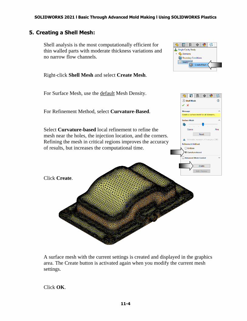
5. Creating a Shell Mesh:
Shell analysis is the most computationally efficient for
thin walled parts with moderate thickness variations and
no narrow flow channels.
Right-click Shell Mesh and select Create Mesh.
For Surface Mesh, use the default Mesh Density.
For Refinement Method, select Curvature-Based.
Select Curvature-based local refinement to refine the
mesh near the holes, the injection location, and the corners.
Refining the mesh in critical regions improves the accuracy
of results, but increases the computational time.
Click Create.
A surface mesh with the current settings is created and displayed in the graphics
area. The Create button is activated again when you modify the current mesh
settings.
Click OK.

SOLIDWORKS 2021 l Basic Through Advanced Mold Making l Using SOLIDWORKS Plastics
11-5
6. Assigning material:
Expand the Material option on the PlasticsManager tree.
Right-click Polymer and select Open Database.
Select the Default Database option (arrow).
Under Plastics Database, expand ABS and click the fisrt checkbox for:
Generic material of ABS.
Click OK.
The Polymer icon now has a green check mark, indicating a material has been
assigned to the part.

SOLIDWORKS 2021 l Basic Through Advanced Mold Making l Using SOLIDWORKS Plastics
11-6
7. Running the flow analysis:
This step predicts the filling pattern of the material melt flow, as it fills the cavity.
In the PlasticsManager tree, expand Run.
Right-click Flow and select Run to start the flow analysis.
A progress bar appears showing the status of the Flow analysis.
It may take a few minutes to complete the analysis.
After the Flow analysis is completed, the Results Property-
Manager lists the plots under the Available Results section.

SOLIDWORKS 2021 l Basic Through Advanced Mold Making l Using SOLIDWORKS Plastics
11-7
8. Viewing the results:
The first available result is the Fill Time plot.
The results shows the time when each runner and cavity domain
is filled.
Click Play Animation to
view the cavity is being
filled with the material.
The Advisor button is automatically enabled to display the
Results Adviser on the right-hand side of the screen.
The Pressure at End of Fill Plot
SOLIDWORKS 2021 l Basic Through Advanced Mold Making l Using SOLIDWORKS Plastics
11-8
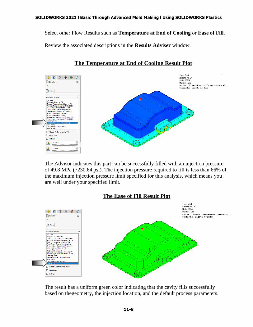
Select other Flow Results such as Temperature at End of Cooling or Ease of Fill.
Review the associated descriptions in the Results Adviser window.
The Temperature at End of Cooling Result Plot
The Advisor indicates this part can be successfully filled with an injection pressure
of 49.8 MPa (7230.64 psi). The injection pressure required to fill is less than 66% of
the maximum injection pressure limit specified for this analysis, which means you
are well under your specified limit.
The Ease of Fill Result Plot
The result has a uniform green color indicating that the cavity fills successfully
based on thegeometry, the injection location, and the default process parameters.

SOLIDWORKS 2021 l Basic Through Advanced Mold Making l Using SOLIDWORKS Plastics
11-9
Click OK to exit the Results.
9. Viewing the report text file:
You can view a summary of the analysis and generate a
project report to communicate key findings and results
of the simulation to the team members.
To open the Summary and Report PropertyManager, do
one of the following:
* In the PlasticsManager tree, expand Results, and
double-click Summary and Report.
or
* In the Plastics CommandManager,
click Generate Report.
A text file of the report is also
generated and stored under Run /
Open Report Text File.
Expand Open Report Text File.
Right-click Flow Text and select
Open.
Internet Explorer is used to display
the report.
The report includes the information
regarding the analysis such as:
Solver Parameter Information,
Process Information, Material Data
Information, Geometric Data
Information, and Filling Stage
Results Summary.
SOLIDWORKS 2021 l Basic Through Advanced Mold Making l Using SOLIDWORKS Plastics
11-10
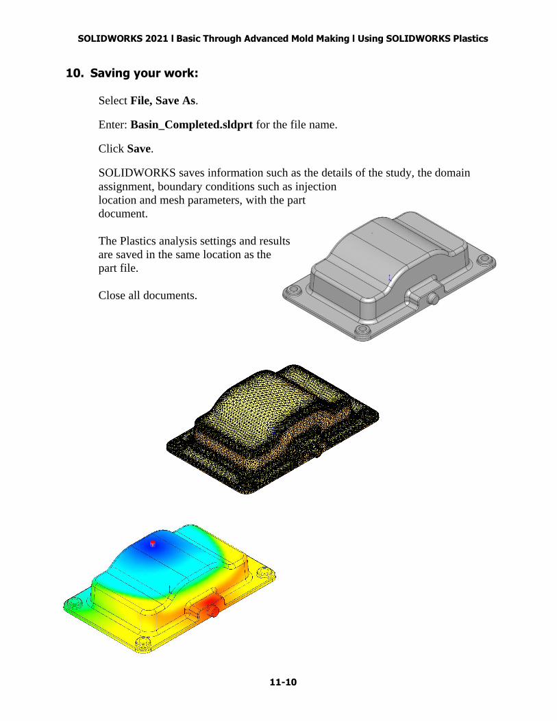
10. Saving your work:
Select File, Save As.
Enter: Basin_Completed.sldprt for the file name.
Click Save.
SOLIDWORKS saves information such as the details of the study, the domain
assignment, boundary conditions such as injection
location and mesh parameters, with the part
document.
The Plastics analysis settings and results
are saved in the same location as the
part file.
Close all documents.