the complete guide to mold making with solidworks 2021
TRANSCRIPT

The Complete Guide to
Mold Making with SOLIDWORKS 2021®
Basic through Advanced Techniques
Paul Tran CSWE, CSWI
SDCP U B L I C AT I O N S www.SDCpublications.com
Better Textbooks. Lower Prices.

Visit the following websites to learn more about this book:
Powered by TCPDF (www.tcpdf.org)

The Complete Guide to Mold Making with SOLIDWORKS 2021 l Surface Repair
2-1
CHAPTER 2 Surface Repair
A lot of times, imported files such as Parasolid, STEP, IGES, ACIS, and others may fail to produce solid or surface geometry because not all CAD systems support the same features and tolerances, or simply because gaps and overlaps exist in the model. This lesson will teach us some of the methods to repair the errors found in a surface model as well as converting it into a solid part. 1. Opening a Parasolid document: Select File, Open. Open a Parasolid document named: Mouse.x_b 2. Running Import Diagnostics: The Import Diagnostics
dialog appears when a Non-SOLIDWORKS native document is
opened. Import diagnostics repairs faulty surfaces, heals gaps between surfaces, and knits repaired surfaces into closed bodies. (3D Interconnect should be OFF for this lesson).
Click YES to run the Import Diagnostics utility. There are 4 gaps found in the model. They are displayed under the Gap Between Faces section. Click Attempt to Heal All (arrow). Both options Heal Gaps and Remove Gaps do not produce the desire results. We will repair the gaps and overlaps
manually instead. Click Cancel .
The Complete Guide to Mold Making with SOLIDWORKS 2021 l Surface Repair
2-2
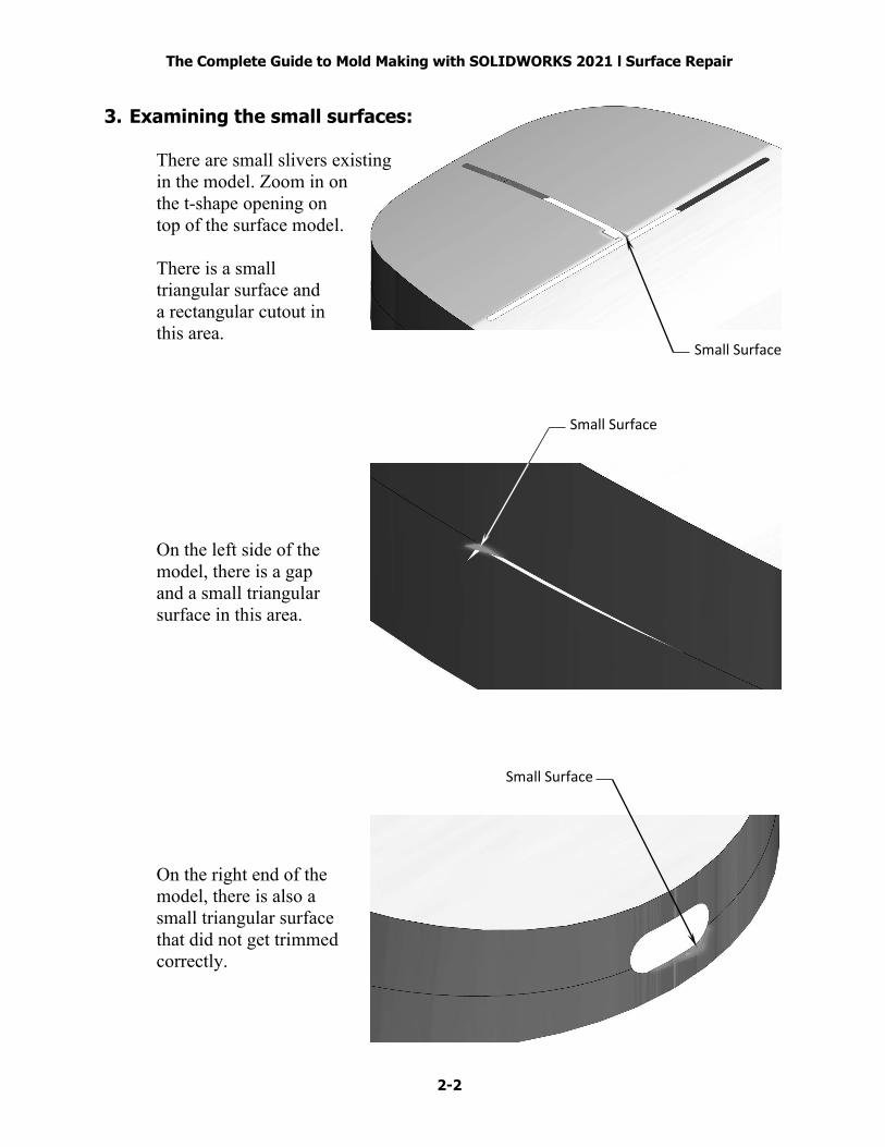
Small Surface
Small Surface
Small Surface
3. Examining the small surfaces: There are small slivers existing in the model. Zoom in on the t-shape opening on
top of the surface model. There is a small triangular surface and a rectangular cutout in this area. On the left side of the model, there is a gap and a small triangular surface in this area. On the right end of the model, there is also a small triangular surface that did not get trimmed correctly.

The Complete Guide to Mold Making with SOLIDWORKS 2021 l Surface Repair
2-3
Select 3 surfaces
Select 13 edges
4. Deleting surfaces: First, we will delete the 3 small triangular surfaces. Change to the Surfaces tab and click Delete Face (arrow). Select the 3 small triangular surfaces as noted. Under Options, select: Delete. Click OK. The selected surfaces are deleted. 5. Deleting hole: Next, we will delete the t-shape opening on the top of the surface model. Click Delete Hole on the Surfaces tab (arrow). Under Selections, select the 13 edges as indicated. Click OK. The opening is removed and the surface is healed.

The Complete Guide to Mold Making with SOLIDWORKS 2021 l Surface Repair
2-4
Select 5 edges
Select 5 edges
6. Patching the openings: Zoom in on the gap on the left side
of the surface model. Click Delete Hole (arrow). Select the 5 edges of the opening. Click OK. The gap is healed. Zoom in on the right end of the model. Click Delete Hole again. Select the 5 edges of the elliptical opening as noted. Click OK. The opening is removed. The gaps and openings are removed from the surface model.
The Complete Guide to Mold Making with SOLIDWORKS 2021 l Surface Repair
2-5
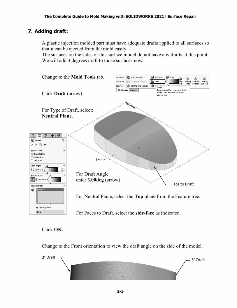
Face to Draft
3° Draft 3° Draft
7. Adding draft: A plastic injection molded part must have adequate drafts applied to all surfaces so that it can be ejected from the mold easily. The surfaces on the sides of this surface model do not have any drafts at this point. We will add 3 degrees draft to those surfaces now. Change to the Mold Tools tab. Click Draft (arrow). For Type of Draft, select: Neutral Plane. For Draft Angle enter 3.00deg (arrow). For Neutral Plane, select the Top plane from the Feature tree. For Faces to Draft, select the side-face as indicated. Click OK. Change to the Front orientation to view the draft angle on the side of the model.

The Complete Guide to Mold Making with SOLIDWORKS 2021 l Surface Repair
2-6
Split face
Mid-Point relations (2X)
8. Creating a split line feature: The Split Line tool splits a surface into 2 surfaces so that each surface can be worked on individually. Select the Front plane and open a new sketch. Sketch a 3-Point-Arc and add the Mid-Point relations as indicated. Add the R15.000 dimension to fully define the sketch. Change to the Surfaces tab and select: Curves, Split Line (arrow). Use the default Projection type. The Current- Sketch is selected automatically as Split Sketch. For Split Face, select the side-face of the model as indicated. Click OK.

The Complete Guide to Mold Making with SOLIDWORKS 2021 l Surface Repair
2-7
Select 2 edges for Hold Line
Select face 1
Select face 2
9. Creating a face fillet: The Split Line created in the last step will be used as a boundary (or Hold Line) to determine the face fillet shape. The radius of the fillet is driven by the distance between the hold line and the edge to fillet. Click Fillet. For Fillet Type, select Face Fillet. For Face Set 1, select the top face. For Face Set 2, select the side-face as noted. For Fillet Parameters, select Hold Line from the drop-down list. For Hold Line, select the 2 edges of the split line. Leave all other parameters at their defaults. Click OK. The fillet shape and size were determined by the hold line (or the boundary of the split line). The fillet on the right end is smaller than the one on the left.
The Complete Guide to Mold Making with SOLIDWORKS 2021 l Surface Repair
2-8
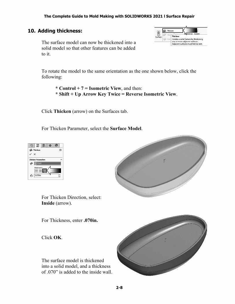
10. Adding thickness: The surface model can now be thickened into a solid model so that other features can be added to it. To rotate the model to the same orientation as the one shown below, click the following: * Control + 7 = Isometric View, and then: * Shift + Up Arrow Key Twice = Reverse Isometric View. Click Thicken (arrow) on the Surfaces tab. For Thicken Parameter, select the Surface Model. For Thicken Direction, select: Inside (arrow). For Thickness, enter .070in. Click OK. The surface model is thickened into a solid model, and a thickness of .070” is added to the inside wall.
The Complete Guide to Mold Making with SOLIDWORKS 2021 l Surface Repair
2-9
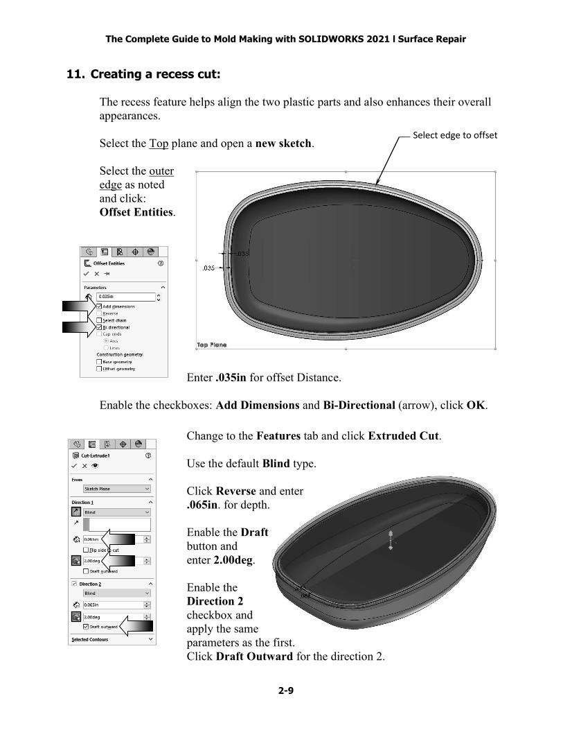
Select edge to offset
11. Creating a recess cut: The recess feature helps align the two plastic parts and also enhances their overall appearances. Select the Top plane and open a new sketch. Select the outer edge as noted and click: Offset Entities. Enter .035in for offset Distance. Enable the checkboxes: Add Dimensions and Bi-Directional (arrow), click OK. Change to the Features tab and click Extruded Cut. Use the default Blind type. Click Reverse and enter .065in. for depth. Enable the Draft button and enter 2.00deg. Enable the Direction 2 checkbox and apply the same parameters as the first. Click Draft Outward for the direction 2.

The Complete Guide to Mold Making with SOLIDWORKS 2021 l Surface Repair
2-10
Recess cut
The recess cut feature is created. It is .065 inches deep and has a 2 degrees draft all around its perimeter. Rotate the model to different orientations to inspect the recess cut feature. Optional: Assign the ABS material to the part, and change the color to gray. 12. Saving your work: Select File, Save As. Enter: Mouse_Completed.sldprt for the file name. Click Save. Close all documents.