solid edge large assemblies white paper · wire harness design exports detailed reports including...
TRANSCRIPT
www.siemens.com/plm
White PaperWith product complexity increasing, more and more companies realize that their current design technology is no longer able to cope. As product lifecycles decrease, engineering departments are inundated with demands to deliver more complex designs in less time, to remain competitive and gain market share. Finding a powerful, fast and efficient design system can be challenging. Solid Edge® large assembly management software, like simplified assemblies and structure-only navigation combined with fast drawing production, allows engineers to reduce costly prototypes by creating fullsize digital mockups.
Siemens PLM Software
Solid Edge Large Assemblies
1A white paper issued by: Siemens PLM Software.
White paper | Solid Edge Large Assemblies
A white paper issued by: Siemens PLM Software. 2
Contents
Executive summary ..........................................................3
Complete digital mockup .................................................4
Systems design ................................................................6
Top down and bottom up .................................................9
Automated part placement ............................................10
Design in context ...........................................................11
Assembly design with synchronous technology ............12
Zones .............................................................................13
Move/copy/rotate assembly command ...........................14
Easy navigation and manipulation .................................15
Smart selection tools .....................................................16
Fast, easy and effective visualization ............................17
Simplified parts ..............................................................18
Hybrid 2D/3D design ......................................................19
Massive assembly size ...................................................21
Structure-only navigation ..............................................22
Simplified assemblies ....................................................23
Lightweight parts ..........................................................24
Fast, productive drawing view layout ............................25
64-bit support ................................................................26
Built-in PDM ...................................................................27
Conclusion .....................................................................28
White paper | Solid Edge Large Assemblies
A white paper issued by: Siemens PLM Software. 3
Executive summaryAs designs become more complex, the number of parts in an assembly often grows. It is not uncommon for Solid Edge customer assemblies to exceed 100,000 parts. Solid Edge large assembly technology helps users to work with large assemblies on a real-time basis, taking automation and intu-ition to a new level. Designers around the world can build and visualize their designs far more quickly than ever before, and minimize the need for costly physical prototypes, all by using Solid Edge in their digital product development process.
Solid Edge Large Assembly capability:
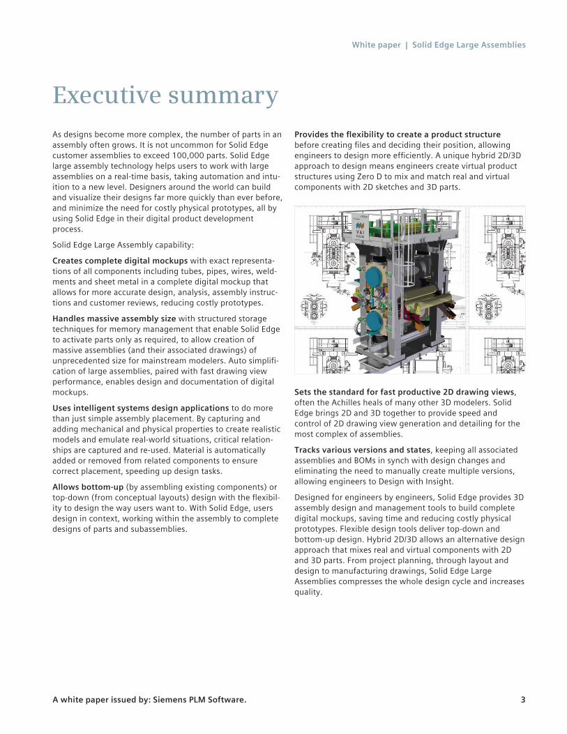
Creates complete digital mockups with exact representa-tions of all components including tubes, pipes, wires, weld-ments and sheet metal in a complete digital mockup that allows for more accurate design, analysis, assembly instruc-tions and customer reviews, reducing costly prototypes.
Handles massive assembly size with structured storage techniques for memory management that enable Solid Edge to activate parts only as required, to allow creation of massive assemblies (and their associated drawings) of unprecedented size for mainstream modelers. Auto simplifi-cation of large assemblies, paired with fast drawing view performance, enables design and documentation of digital mockups.
Uses intelligent systems design applications to do more than just simple assembly placement. By capturing and adding mechanical and physical properties to create realistic models and emulate real-world situations, critical relation-ships are captured and re-used. Material is automatically added or removed from related components to ensure correct placement, speeding up design tasks.
Allows bottom-up (by assembling existing components) or top-down (from conceptual layouts) design with the flexibil-ity to design the way users want to. With Solid Edge, users design in context, working within the assembly to complete designs of parts and subassemblies.
Provides the flexibility to create a product structure before creating files and deciding their position, allowing engineers to design more efficiently. A unique hybrid 2D/3D approach to design means engineers create virtual product structures using Zero D to mix and match real and virtual components with 2D sketches and 3D parts.
Sets the standard for fast productive 2D drawing views, often the Achilles heals of many other 3D modelers. Solid Edge brings 2D and 3D together to provide speed and control of 2D drawing view generation and detailing for the most complex of assemblies.
Tracks various versions and states, keeping all associated assemblies and BOMs in synch with design changes and eliminating the need to manually create multiple versions, allowing engineers to Design with Insight.
Designed for engineers by engineers, Solid Edge provides 3D assembly design and management tools to build complete digital mockups, saving time and reducing costly physical prototypes. Flexible design tools deliver top-down and bottom-up design. Hybrid 2D/3D allows an alternative design approach that mixes real and virtual components with 2D and 3D parts. From project planning, through layout and design to manufacturing drawings, Solid Edge Large Assemblies compresses the whole design cycle and increases quality.
White paper | Solid Edge Large Assemblies
A white paper issued by: Siemens PLM Software. 4
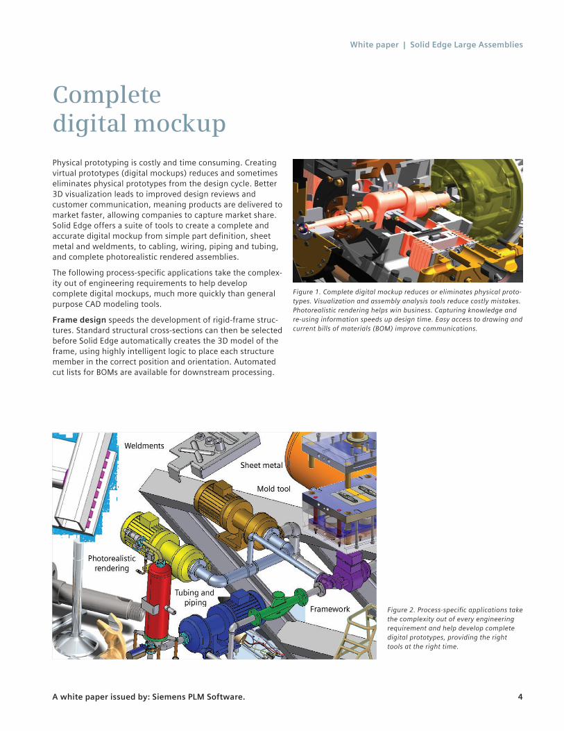
Complete digital mockupPhysical prototyping is costly and time consuming. Creating virtual prototypes (digital mockups) reduces and sometimes eliminates physical prototypes from the design cycle. Better 3D visualization leads to improved design reviews and customer communication, meaning products are delivered to market faster, allowing companies to capture market share. Solid Edge offers a suite of tools to create a complete and accurate digital mockup from simple part definition, sheet metal and weldments, to cabling, wiring, piping and tubing, and complete photorealistic rendered assemblies.
The following process-specific applications take the complex-ity out of engineering requirements to help develop complete digital mockups, much more quickly than general purpose CAD modeling tools.
Frame design speeds the development of rigid-frame struc-tures. Standard structural cross-sections can then be selected before Solid Edge automatically creates the 3D model of the frame, using highly intelligent logic to place each structure member in the correct position and orientation. Automated cut lists for BOMs are available for downstream processing.
Figure 2. Process-specific applications take the complexity out of every engineering requirement and help develop complete digital prototypes, providing the right tools at the right time.
Figure 1. Complete digital mockup reduces or eliminates physical proto-types. Visualization and assembly analysis tools reduce costly mistakes. Photorealistic rendering helps win business. Capturing knowledge and re-using information speeds up design time. Easy access to drawing and current bills of materials (BOM) improve communications.
White paper | Solid Edge Large Assemblies
A white paper issued by: Siemens PLM Software. 5
Solid Edge treats weldments as part of the design process. A unique part number is applied to the weldments containing a group of constituent parts. Weld preparation, treatments and machining operations are all captured as part of the welding process with component drawings as well as pre-weld and post-machining views. Automated BOMs are avail-able for each weldment.
Solid Edge XpresRoute is an integrated application that eases the design of routed pipe work and tubes. A compre-hensive set of design tools helps designers quickly route and model piping and tubing within Solid Edge assemblies. Designers easily create 3D paths for the routed components to follow, and the tube or piping system is created along the path segments, using specified attributes such as size, color, extents and end treatments. For piping systems, 3D pipes, fittings and components are automatically positioned and correctly oriented upon population. All pipes and tubes are fully associative, if the assembly in which they are constructed is modified; they automatically adapt to design changes. Accurate cut lists and component BOMs can be created, and Solid Edge XpresRoute automatically produces bend tables for use with tube bending machines.
Wire harness design supports the routing and creation of cable and wiring systems. Designers can easily import connectivity data from electronic CAD systems to automate harness creation and a full compliment of tools are available for routing. If a wire’s minimum bend radius has been exceeded, a visual indication shows the problem. Solid Edge Wire Harness Design exports detailed reports including cut lengths, attributes, physical properties and other important information. Electronic CAD systems can import the reports for analysis and manufacturing support.
Solid Edge standard parts library is a powerful parts management system that allows designers to define, store, select and position commonly used parts – like fasteners, bearings, pipe fittings and structural steel members – quickly and efficiently, enabling rapid and precise completion of 3D assemblies. With Solid Edge standard parts, companies establish and share their own standards, beginning with the parts delivered with Solid Edge or the optional libraries, allowing designers to concentrate on creative design and not on routine modeling tasks.
Explode/render/animate in Solid Edge helps bring designs to life with full photorealistic rendering including graphical light placement, soft shadows, and reflections. Assembly sequence movies can be created with powerful explode tools. A sophisticated time-line helps designers set the exact sequence of operations showing when motors start, shafts rotate, parts fade and explosions occur. Animations can be captured and saved to movies, even with photorealistic or artistic rendering.
The benefits of digital mockup extend far beyond the engi-neering department. Purchasing can quickly view released drawings and current bills of materials to improve supplier communications. Sales and Marketing are able to include easy-to-understand 3D designs, complete with photorealistic rendered images, to help win business. And to comply with certification, technical and instruction manuals are quick and easy to produce. Complete digital mockups become the central resource of any organization on which all members can rely.

White paper | Solid Edge Large Assemblies
A white paper issued by: Siemens PLM Software. 6
Systems designThe creation of digital mockups is at the center of almost all 3D design processes. Where traditional assembly design focuses primarily on how parts fit together, systems design places additional emphasis on the function of a product and how components interact. Designers are given the power to advance beyond fit, to create intelligently, functionally (as well as physically) to create realistic models that emulate real-world situations. In virtual systems design, a group of interacting parts and subassemblies are modeled as a “whole,” with sufficient information to describe how compo-nents relate to each other and how they need to perform to meet design criteria. Critical relationships are captured and re-used, material is automatically added or removed from related components to ensure correct placement, and moving parts maintain their predefined paths and loads, while sensors monitor critical distances and other variables that affect desired performance.
Systems design offers a unique approach that allows users to define, store and re-use cohesive sets of parts, features and constraints as a single functional system. Adjustable assemblies that allow adaptable placement of the same subassembly to accommodate varying positions and new motion analysis tools that automatically simulate mecha-nisms under the influence of forces, further reduce the need
for physical prototypes. These tools, combined with an impressive new array of relationship controls, features, and the ability to capture and re-use this design intent as a part of the systems library makes Solid Edge a leader in the area of systems design.
At the heart of systems design are systems libraries, the capability to define, store and re-use complete systems of parts – more than just subassemblies systems retain their knowledge for re-use when placed in other assemblies.
Fastener systems This capability applies a high level of intelligence when assembling components using mechanical fasteners, such as nuts, bolts, rivets etc. For example, users can pick a hole or set of holes in the assembly (Solid Edge first checks the holes are available to use), looking for things like clearance and tapped holes being lined up correctly. Then by filtering the standard parts database, Solid Edge displays only the parts that are valid for the selected holes; a user can populate the holes with the complete fastener system of choice. This may be a single bolt, a bolt, washers and nut, or any other combination of relevant fasteners.
Capture fit Assembly tools in Solid Edge go beyond simply positioning components. Cognitive assembly logic captures and stresses component relationships as they are positioned.
Figure 3. A system is a group of interacting parts and subassemblies, each containing sufficient knowledge to describe how it needs to perform in order to meet the design intent of the product.
White paper | Solid Edge Large Assemblies
A white paper issued by: Siemens PLM Software. 7
When parts are subsequently placed, relationships are already inferred; only the adjoining part relationships are required.
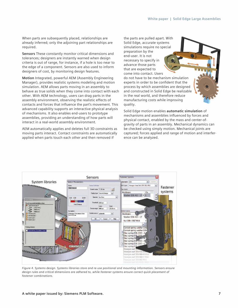
Sensors These constantly monitor critical dimensions and tolerances; designers are instantly warned when design criteria is out of range, for instance, if a hole is too near to the edge of a component. Sensors are also used to inform designers of cost, by monitoring design features.
Motion Integrated, powerful AEM (Assembly Engineering Manager), provides realistic systems modeling and motion simulation. AEM allows parts moving in an assembly to behave as true solids when they come into contact with each other. With AEM technology, users can drag parts in the assembly environment, observing the realistic effects of contacts and forces that influence the part’s movement. This advanced capability supports an interactive physical analysis of mechanisms. It also enables end-users to prototype assemblies, providing an understanding of how parts will interact in a real-world assembly environment.
AEM automatically applies and deletes full 3D constraints as moving parts interact. Contact constraints are automatically applied when parts touch each other and then removed if
the parts are pulled apart. With Solid Edge, accurate systems simulations require no special preparation by the end-user. It is not necessary to specify in advance those parts that are expected to come into contact. Users do not have to be mechanism simulation experts in order to be confident that the process by which assemblies are designed and constructed in Solid Edge be realizable in the real world, and therefore reduce manufacturing costs while improving quality.
Solid Edge motion enables automatic simulation of mechanisms and assemblies influenced by forces and physical contact, enabled by the mass and center-of- gravity of parts in an assembly. Mechanical dynamics can be checked using simply motion. Mechanical joints are captured; forces applied and range of motion and interfer-ence can be analyzed.
Figure 4. Systems design. Systems libraries store and re-use positional and mounting information. Sensors ensure design rules and critical dimensions are adhered to, while fastener systems ensure correct quick placement of fastener combinations.
White paper | Solid Edge Large Assemblies
A white paper issued by: Siemens PLM Software. 8
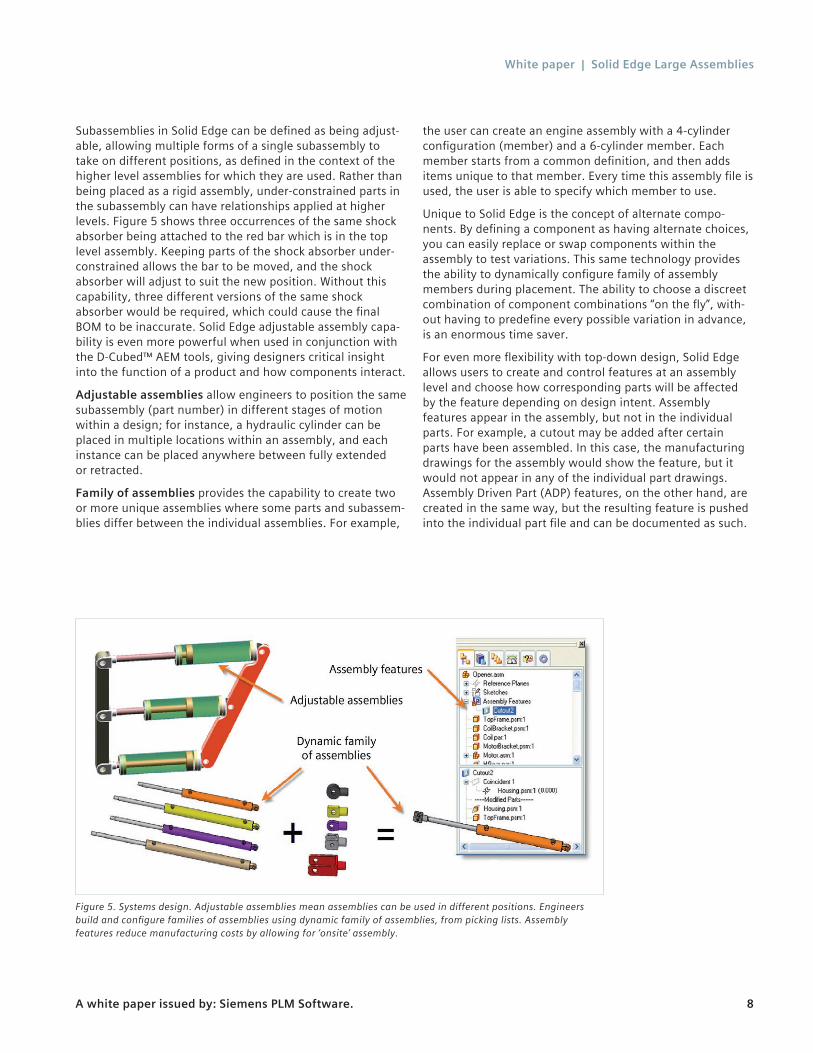
Subassemblies in Solid Edge can be defined as being adjust-able, allowing multiple forms of a single subassembly to take on different positions, as defined in the context of the higher level assemblies for which they are used. Rather than being placed as a rigid assembly, under-constrained parts in the subassembly can have relationships applied at higher levels. Figure 5 shows three occurrences of the same shock absorber being attached to the red bar which is in the top level assembly. Keeping parts of the shock absorber under-constrained allows the bar to be moved, and the shock absorber will adjust to suit the new position. Without this capability, three different versions of the same shock absorber would be required, which could cause the final BOM to be inaccurate. Solid Edge adjustable assembly capa-bility is even more powerful when used in conjunction with the D-Cubed™ AEM tools, giving designers critical insight into the function of a product and how components interact.
Adjustable assemblies allow engineers to position the same subassembly (part number) in different stages of motion within a design; for instance, a hydraulic cylinder can be placed in multiple locations within an assembly, and each instance can be placed anywhere between fully extended or retracted.
Family of assemblies provides the capability to create two or more unique assemblies where some parts and subassem-blies differ between the individual assemblies. For example,
the user can create an engine assembly with a 4-cylinder configuration (member) and a 6-cylinder member. Each member starts from a common definition, and then adds items unique to that member. Every time this assembly file is used, the user is able to specify which member to use.
Unique to Solid Edge is the concept of alternate compo-nents. By defining a component as having alternate choices, you can easily replace or swap components within the assembly to test variations. This same technology provides the ability to dynamically configure family of assembly members during placement. The ability to choose a discreet combination of component combinations “on the fly”, with-out having to predefine every possible variation in advance, is an enormous time saver.
For even more flexibility with top-down design, Solid Edge allows users to create and control features at an assembly level and choose how corresponding parts will be affected by the feature depending on design intent. Assembly features appear in the assembly, but not in the individual parts. For example, a cutout may be added after certain parts have been assembled. In this case, the manufacturing drawings for the assembly would show the feature, but it would not appear in any of the individual part drawings. Assembly Driven Part (ADP) features, on the other hand, are created in the same way, but the resulting feature is pushed into the individual part file and can be documented as such.
Figure 5. Systems design. Adjustable assemblies mean assemblies can be used in different positions. Engineers build and configure families of assemblies using dynamic family of assemblies, from picking lists. Assembly features reduce manufacturing costs by allowing for ‘onsite’ assembly.
White paper | Solid Edge Large Assemblies
A white paper issued by: Siemens PLM Software. 9
Top down and bottom upBuilding components in isolation and then building an assembly from them is known as bottom up. Engineers commonly use this approach when re-using a lot of data from existing designs or start a new project. Top down allows designs to be continued using components already in position for reference.
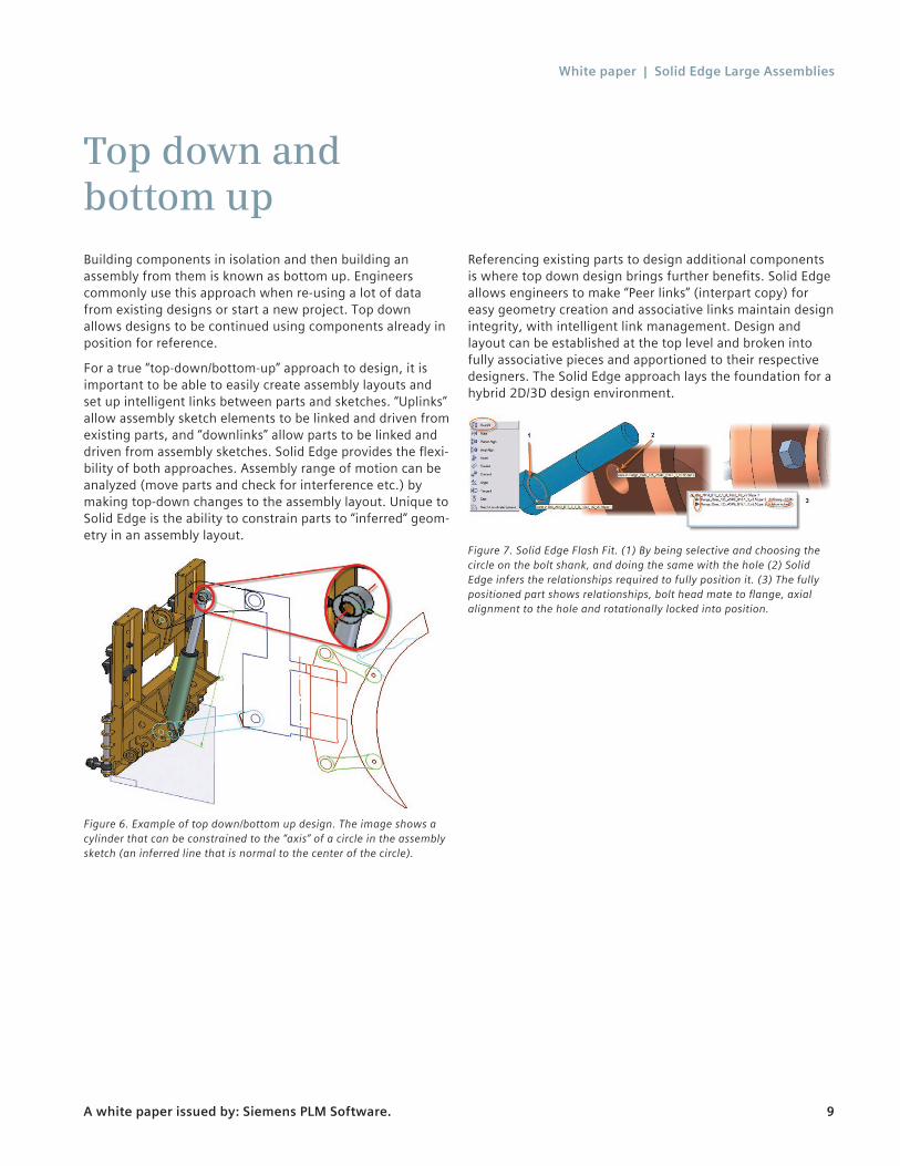
For a true “top-down/bottom-up” approach to design, it is important to be able to easily create assembly layouts and set up intelligent links between parts and sketches. “Uplinks” allow assembly sketch elements to be linked and driven from existing parts, and “downlinks” allow parts to be linked and driven from assembly sketches. Solid Edge provides the flexi-bility of both approaches. Assembly range of motion can be analyzed (move parts and check for interference etc.) by making top-down changes to the assembly layout. Unique to Solid Edge is the ability to constrain parts to “inferred” geom-etry in an assembly layout.
Figure 6. Example of top down/bottom up design. The image shows a cylinder that can be constrained to the “axis” of a circle in the assembly sketch (an inferred line that is normal to the center of the circle).
Referencing existing parts to design additional components is where top down design brings further benefits. Solid Edge allows engineers to make “Peer links” (interpart copy) for easy geometry creation and associative links maintain design integrity, with intelligent link management. Design and layout can be established at the top level and broken into fully associative pieces and apportioned to their respective designers. The Solid Edge approach lays the foundation for a hybrid 2D/3D design environment.
Figure 7. Solid Edge Flash Fit. (1) By being selective and choosing the circle on the bolt shank, and doing the same with the hole (2) Solid Edge infers the relationships required to fully position it. (3) The fully positioned part shows relationships, bolt head mate to flange, axial alignment to the hole and rotationally locked into position.
White paper | Solid Edge Large Assemblies
A white paper issued by: Siemens PLM Software. 10
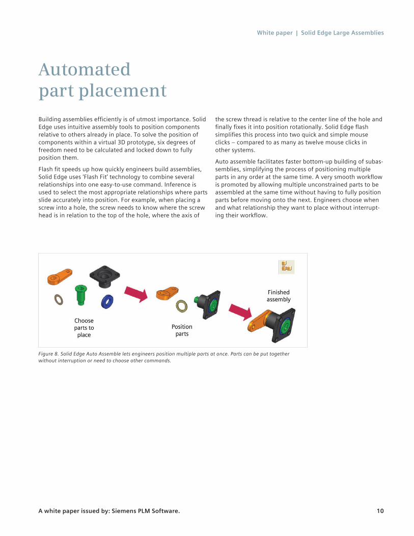
Automated part placementBuilding assemblies efficiently is of utmost importance. Solid Edge uses intuitive assembly tools to position components relative to others already in place. To solve the position of components within a virtual 3D prototype, six degrees of freedom need to be calculated and locked down to fully position them.
Flash fit speeds up how quickly engineers build assemblies, Solid Edge uses ‘Flash Fit’ technology to combine several relationships into one easy-to-use command. Inference is used to select the most appropriate relationships where parts slide accurately into position. For example, when placing a screw into a hole, the screw needs to know where the screw head is in relation to the top of the hole, where the axis of
the screw thread is relative to the center line of the hole and finally fixes it into position rotationally. Solid Edge flash simplifies this process into two quick and simple mouse clicks – compared to as many as twelve mouse clicks in other systems.
Auto assemble facilitates faster bottom-up building of subas-semblies, simplifying the process of positioning multiple parts in any order at the same time. A very smooth workflow is promoted by allowing multiple unconstrained parts to be assembled at the same time without having to fully position parts before moving onto the next. Engineers choose when and what relationship they want to place without interrupt-ing their workflow.
Figure 8. Solid Edge Auto Assemble lets engineers position multiple parts at once. Parts can be put together without interruption or need to choose other commands.
White paper | Solid Edge Large Assemblies
A white paper issued by: Siemens PLM Software. 11
Design in contextBeing able to create or complete new components in relation to their surrounding environment is critical for accurate design work. Solid Edge enables engineers to work within the context of an assembly to complete designs in this way. Associative links between designs (peer to peer) speed creation and updating of designs. Engineers are able to better visualize designs and manipulate and analyze mecha-nisms to design right the first time, all while maintaining part integrity in the context of the entire assembly.
White paper | Solid Edge Large Assemblies
A white paper issued by: Siemens PLM Software. 12
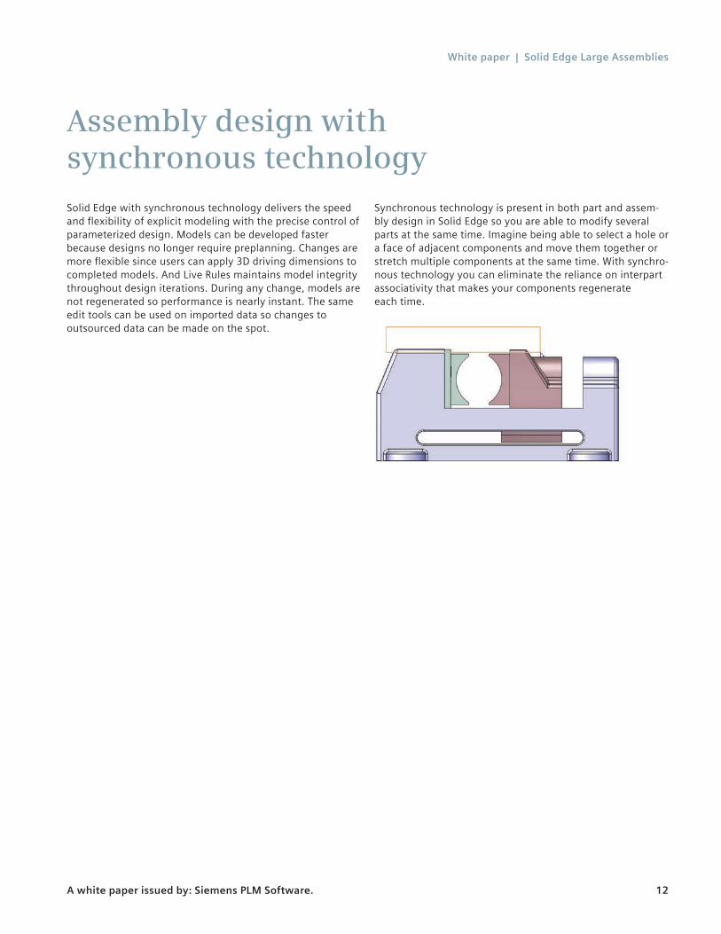
Assembly design with synchronous technologySolid Edge with synchronous technology delivers the speed and flexibility of explicit modeling with the precise control of parameterized design. Models can be developed faster because designs no longer require preplanning. Changes are more flexible since users can apply 3D driving dimensions to completed models. And Live Rules maintains model integrity throughout design iterations. During any change, models are not regenerated so performance is nearly instant. The same edit tools can be used on imported data so changes to outsourced data can be made on the spot.
Synchronous technology is present in both part and assem-bly design in Solid Edge so you are able to modify several parts at the same time. Imagine being able to select a hole or a face of adjacent components and move them together or stretch multiple components at the same time. With synchro-nous technology you can eliminate the reliance on interpart associativity that makes your components regenerate each time.

White paper | Solid Edge Large Assemblies
A white paper issued by: Siemens PLM Software. 13
Zones make working with massive assemblies even more manageable and boost performance, allowing designers to define a permanent range box to isolate areas of large designs they are responsible for at a subsystem level. Intelligent caching allows retrieval of only the parts in the zone, without having to open component files to determine if they lie in the zone or not. This creates a significant performance boost when switching zones or opening a massive assembly.
Zones
Figure 9. Solid Edge selection tools, options and display configurations provide quick, convenient ways to select and choose component displays.
White paper | Solid Edge Large Assemblies
A white paper issued by: Siemens PLM Software. 14
Move/copy/rotate assembly commandTo help designers lay out factory floors and/or machine designs, a new manual component positioning capability allows existing subassemblies to be quickly copied, moved, rotated or arrayed within an assembly. To remove any restrictions, assembly relationships to existing components are ignored, while those integral to the subassembly remain intact. Subassemblies can be simply dragged to a new location or precisely moved using coordinates, vectors or exiting components.
White paper | Solid Edge Large Assemblies
A white paper issued by: Siemens PLM Software. 15
Easy navigation and manipulationHaving the ability to visualize the whole or part of a design provides great benefits to designers. Providing intuitive navi-gation and manipulation that allows sorting and display of components by description, common attributes, placement or size, makes the task easier and saves time. Engineers constantly need to be able to quickly show and hide different combinations of components while performing daily design tasks.
With simple designs, any system can easily cope; however with today’s designs becoming increasingly complex (assem-blies with 10,000 parts are commonplace) finding, selecting and configuring what needs to be displayed can become an overhead that quickly reduces the benefits of 3D design.
Solid Edge goes beyond simple selection tools for selecting parts or subassemblies, or showing and hiding components. See figure 9. The process engineers go through while they work on designs has been studied and understood by Solid Edge product planning. It is no mistake that powerful tools to complete these tasks have been developed to allow engineers to quickly pinpoint relevant parts and continue to design. For example, Solid Edge has selection tools for selecting parts relative to their size, location, identity or visi-bility. Query select tools select parts based on their proper-ties. Display configurations are saved so engineers can return to the same point at a later time. Configurations save valu-able system resources allowing engineers to open a design with only the parts they need.
White paper | Solid Edge Large Assemblies
A white paper issued by: Siemens PLM Software. 16
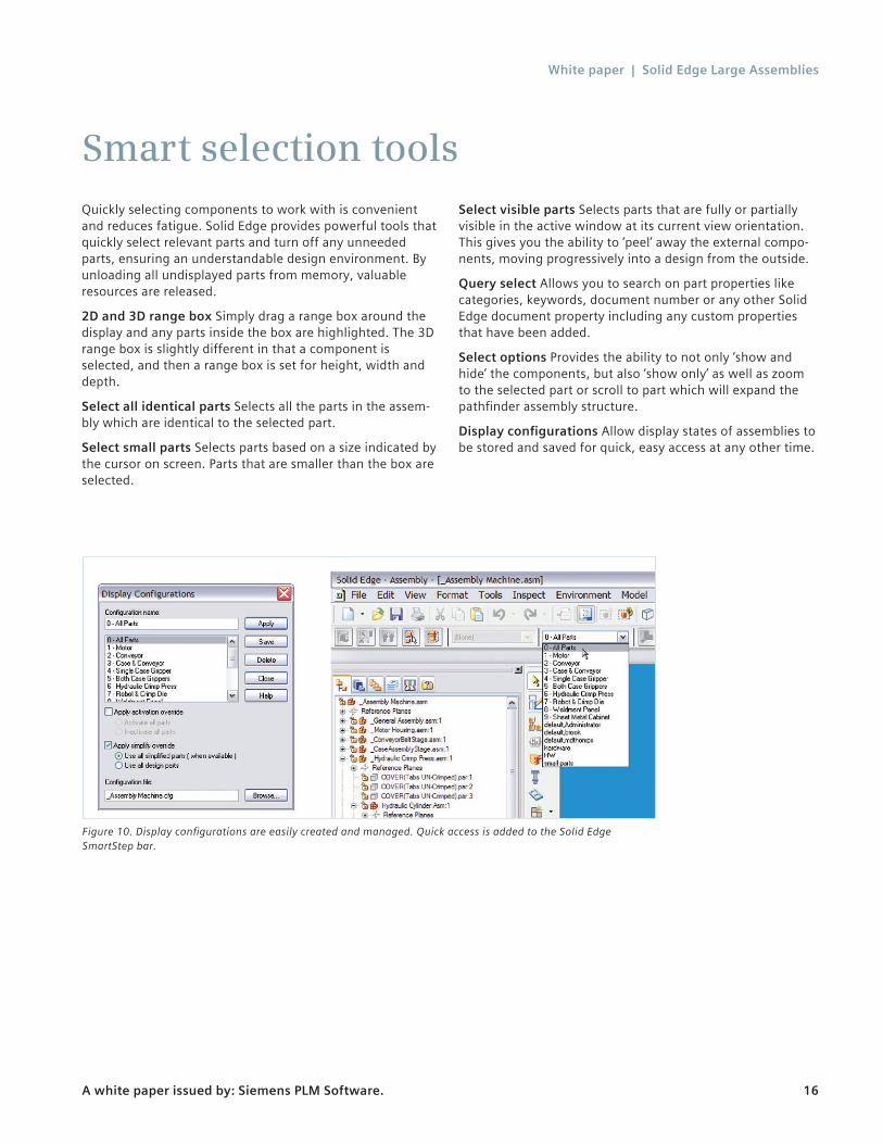
Smart selection toolsQuickly selecting components to work with is convenient and reduces fatigue. Solid Edge provides powerful tools that quickly select relevant parts and turn off any unneeded parts, ensuring an understandable design environment. By unloading all undisplayed parts from memory, valuable resources are released.
2D and 3D range box Simply drag a range box around the display and any parts inside the box are highlighted. The 3D range box is slightly different in that a component is selected, and then a range box is set for height, width and depth.
Select all identical parts Selects all the parts in the assem-bly which are identical to the selected part.
Select small parts Selects parts based on a size indicated by the cursor on screen. Parts that are smaller than the box are selected.
Select visible parts Selects parts that are fully or partially visible in the active window at its current view orientation. This gives you the ability to ‘peel’ away the external compo-nents, moving progressively into a design from the outside.
Query select Allows you to search on part properties like categories, keywords, document number or any other Solid Edge document property including any custom properties that have been added.
Select options Provides the ability to not only ‘show and hide’ the components, but also ‘show only’ as well as zoom to the selected part or scroll to part which will expand the pathfinder assembly structure.
Display configurations Allow display states of assemblies to be stored and saved for quick, easy access at any other time.
Figure 10. Display configurations are easily created and managed. Quick access is added to the Solid Edge SmartStep bar.
White paper | Solid Edge Large Assemblies
A white paper issued by: Siemens PLM Software. 17
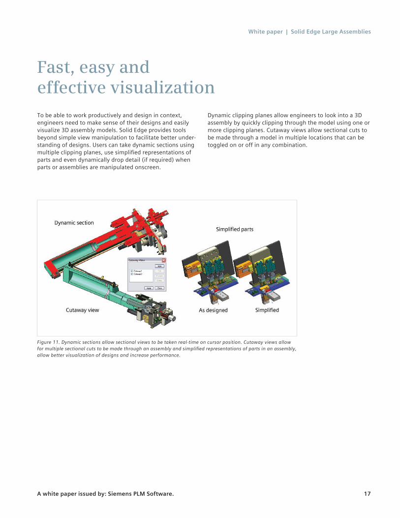
Fast, easy and effective visualizationTo be able to work productively and design in context, engineers need to make sense of their designs and easily visualize 3D assembly models. Solid Edge provides tools beyond simple view manipulation to facilitate better under-standing of designs. Users can take dynamic sections using multiple clipping planes, use simplified representations of parts and even dynamically drop detail (if required) when parts or assemblies are manipulated onscreen.
Dynamic clipping planes allow engineers to look into a 3D assembly by quickly clipping through the model using one or more clipping planes. Cutaway views allow sectional cuts to be made through a model in multiple locations that can be toggled on or off in any combination.
Figure 11. Dynamic sections allow sectional views to be taken real-time on cursor position. Cutaway views allow for multiple sectional cuts to be made through an assembly and simplified representations of parts in an assembly, allow better visualization of designs and increase performance.

White paper | Solid Edge Large Assemblies
A white paper issued by: Siemens PLM Software. 18
Simplified partsUsing a simplified version of complex parts can significantly reduce the amount of detail that needs to be viewed and worked with. Engineers can better visualize the design and also gain display performance. The simplify technology in Solid Edge allows design engineers to de-feature parts – by detail, type or size of feature – without deleting the design intent. By storing both the designed and simplified views, engineers can quickly switch between ‘as designed’ and ‘simplified’ at will. Unlike more traditional methods, simplify-ing the features in the part does not break or remove any assembly relationships that rely on those features.
Display tools increase display performance on large assem-blies. Solid Edge culls unnecessary detail while manipulating a view. Culling instructs the display system to ignore display requests for certain objects if it detects that there is an excessive overhead on display performance.
Refresh scale controls the speed and precision of the magni-fication commands such as zoom area, zoom and fit. Solid Edge offers tools to change the display of the model for better clarity, such as, wire frame, wire frame with hidden edge display, shaded only and shaded visible hidden line (VHL). While shaded models look nice, many engineers choose to work in wire frame for better clarity.
White paper | Solid Edge Large Assemblies
A white paper issued by: Siemens PLM Software. 19
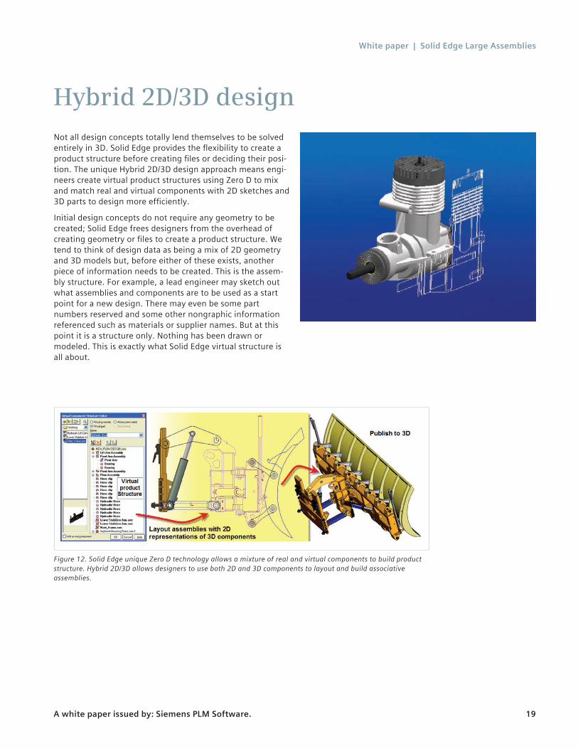
Hybrid 2D/3D designNot all design concepts totally lend themselves to be solved entirely in 3D. Solid Edge provides the flexibility to create a product structure before creating files or deciding their posi-tion. The unique Hybrid 2D/3D design approach means engi-neers create virtual product structures using Zero D to mix and match real and virtual components with 2D sketches and 3D parts to design more efficiently.
Initial design concepts do not require any geometry to be created; Solid Edge frees designers from the overhead of creating geometry or files to create a product structure. We tend to think of design data as being a mix of 2D geometry and 3D models but, before either of these exists, another piece of information needs to be created. This is the assem-bly structure. For example, a lead engineer may sketch out what assemblies and components are to be used as a start point for a new design. There may even be some part numbers reserved and some other nongraphic information referenced such as materials or supplier names. But at this point it is a structure only. Nothing has been drawn or modeled. This is exactly what Solid Edge virtual structure is all about.
Figure 12. Solid Edge unique Zero D technology allows a mixture of real and virtual components to build product structure. Hybrid 2D/3D allows designers to use both 2D and 3D components to layout and build associative assemblies.
White paper | Solid Edge Large Assemblies
A white paper issued by: Siemens PLM Software. 20
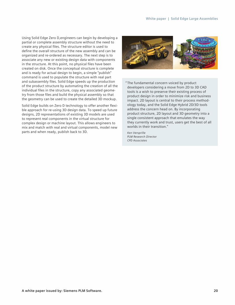
Using Solid Edge Zero D,engineers can begin by developing a partial or complete assembly structure without the need to create any physical files. The structure editor is used to define the overall structure of the new assembly and can be organized and re-ordered as necessary. The next step is to associate any new or existing design data with components in the structure. At this point, no physical files have been created on disk. Once the conceptual structure is complete and is ready for actual design to begin, a simple “publish” command is used to populate the structure with real part and subassembly files. Solid Edge speeds up the production of the product structure by automating the creation of all the individual files in the structure, copy any associated geome-try from those files and build the physical assembly so that the geometry can be used to create the detailed 3D mockup.
Solid Edge builds on Zero D technology to offer another flexi-ble approach for re-using 3D design data. To speed up future designs, 2D representations of existing 3D models are used to represent real components in the virtual structure for complex design or machine layout. This allows engineers to mix and match with real and virtual components, model new parts and when ready, publish back to 3D.
“ The fundamental concern voiced by product developers considering a move from 2D to 3D CAD tools is a wish to preserve their existing process of product design in order to minimize risk and business impact. 2D layout is central to their process method-ology today, and the Solid Edge Hybrid 2D/3D tools address the concern head on. By incorporating product structure, 2D layout and 3D geometry into a single consistent approach that emulates the way they currently work and trust, users get the best of all worlds in their transition.”
Ken Versprille PLM Research Director CPD Associates
White paper | Solid Edge Large Assemblies
A white paper issued by: Siemens PLM Software. 21
Massive assembly sizeStructured storage techniques for memory management enables Solid Edge to activate parts only as required, to allow creation of massive assemblies (and their associated drawings) of unprecedented size for mainstream modelers. Auto simplification of large assemblies, paired with fast drawing view performance, enables design and documenta-tion of digital mockups.
It is not uncommon for Solid Edge assemblies to exceed 100,000+ parts in a top-level assembly file. Solid Edge large assembly technology supports real-world design working with large assemblies, tools that take automation and intu-ition to a new level to help designers across the world build and visualize their designs far more quickly than ever before.
As assemblies get larger and designs become more complex, Solid Edge deploys new patent-pending technology to allow engineers to work on the largest assemblies. Auto simplifica-tion of assemblies and structure-only navigation make the most efficient use of available resources speeding up the design process by freeing up system memory and allowing the graphics display to work more efficiently. Drawing production is also important. Solid Edge Draft takes advan-tage of these assembly enhancements, and with draft quality drawing views, allows Solid Edge to create the fastest production ready drawings.
White paper | Solid Edge Large Assemblies
A white paper issued by: Siemens PLM Software. 22
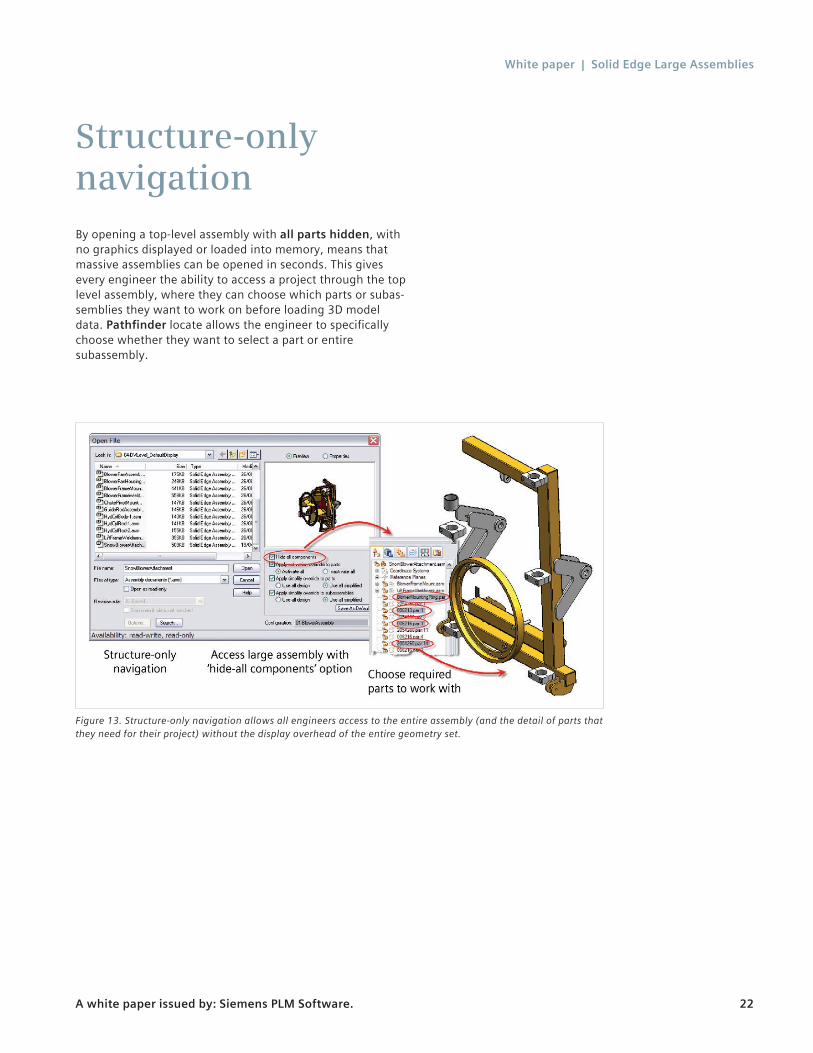
Structure-only navigationBy opening a top-level assembly with all parts hidden, with no graphics displayed or loaded into memory, means that massive assemblies can be opened in seconds. This gives every engineer the ability to access a project through the top level assembly, where they can choose which parts or subas-semblies they want to work on before loading 3D model data. Pathfinder locate allows the engineer to specifically choose whether they want to select a part or entire subassembly.
Figure 13. Structure-only navigation allows all engineers access to the entire assembly (and the detail of parts that they need for their project) without the display overhead of the entire geometry set.
White paper | Solid Edge Large Assemblies
A white paper issued by: Siemens PLM Software. 23
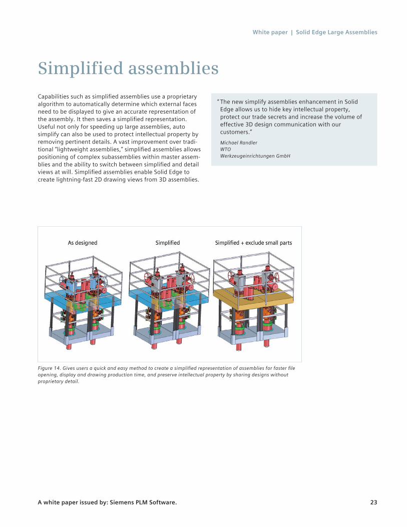
Simplified assembliesCapabilities such as simplified assemblies use a proprietary algorithm to automatically determine which external faces need to be displayed to give an accurate representation of the assembly. It then saves a simplified representation. Useful not only for speeding up large assemblies, auto simplify can also be used to protect intellectual property by removing pertinent details. A vast improvement over tradi-tional “lightweight assemblies,” simplified assemblies allows positioning of complex subassemblies within master assem-blies and the ability to switch between simplified and detail views at will. Simplified assemblies enable Solid Edge to create lightning-fast 2D drawing views from 3D assemblies.
Figure 14. Gives users a quick and easy method to create a simplified representation of assemblies for faster file opening, display and drawing production time, and preserve intellectual property by sharing designs without proprietary detail.
“ The new simplify assemblies enhancement in Solid Edge allows us to hide key intellectual property, protect our trade secrets and increase the volume of effective 3D design communication with our customers.”
Michael Randler WTO Werkzeugeinrichtungen GmbH

White paper | Solid Edge Large Assemblies
A white paper issued by: Siemens PLM Software. 24
Lightweight partsWorking on large assemblies will consume hardware resources on any system, eventually running out all together given enough parts (many thousand) unless they are managed. Displaying all parts with all the geometry loaded into memory is often a real waste of valuable memory, CPU and graphics performance. Solid Edge lightweight part tech-nology allows engineers to open large assembly files with only the lightweight graphical information loaded into memory. This means that files open faster (less information to load), and fewer system resources are used.
Mostly after a top-level assembly has been opened, engi-neers need to quickly focus on the areas of the design they are working on. This requires most component displays to be turned off, while leaving relevant components in view for reference. Other systems using this approach often leave parts not displayed still in memory. By easily selecting irrele-vant parts and turning them off, Solid Edge frees up system resources by unloading them from memory. So engineers can start to work immediately. Solid Edge loads and unloads parts as required. The end result is that engineers interact with the large assembly without interruption or delay, with a more responsive system.

White paper | Solid Edge Large Assemblies
A white paper issued by: Siemens PLM Software. 25
Fast, productive drawing view layoutSolid Edge sets the standard for fast productive 2D drawing views. Drawings are a key part of the process for manufac-ture, inspection and documentation of designs – often the Achilles heals of many other 3D modelers. Solid Edge brings 2D and 3D together to provide speed and control of 2D drawings for the most complex of assemblies.
Solid Edge Draft is unsurpassed for creation of 2D drawing in its market. Assembly-specific drafting automates processes to “complete” drawings expeditiously, assure that all parts are accounted for and keep track of revisions as they occur. Solid Edge production-ready drafting adheres to inter-nationally recognized drawing standards to automate draw-ing production. Draft quality drawing views ensure engineers can quickly set out drawing view composition, fast view placement and drawing updates. Fully associative parts lists with auto ballooning are produced. Designs inevitably will go through design reviews and changes will occur, dimensions are automatically updated and changes are communicated through the dimension and annotation tracker. Exploded views help communicate assembly instructions, show all parts and are useful for technical publications.
Simplified assemblies allow Solid Edge to create the fastest 2D drawing views on the market. A simple option during drawing view creation enables Solid Edge to create drawing
views up to 60 times (typically 2-8X) faster than with all details on, without any appreciable difference in drawing view quality.
Solid Edge allows users to create a draft quality view of a single part, assembly file or simplified assembly. This allows engineers to quickly create drawings and drawing composi-tions. As designs change, the drawing views can be quickly updated. When the drawing is ready for release, should it be necessary, draft quality views can be converted to high qual-ity view for final detailing and printed in precise form when required. This powerful functionality ensures anyone who needs to create complex drawings of extremely large assem-blies in record time.
A drawing review mode in Solid Edge allows rapid opening of a drawing for reviewing, adding dimensions, measuring or printing regardless of how big or detailed the drawing is. Inactive drawings as they are referred to allow dimensions and annotations to be added, and extract part numbers and bill of materials. Drawing views can also be ‘activated’ on the fly if needed to establish a ‘true’ dimension in an isometric view for instance. This model allows drawing reviews with or without 3D, quick print jobs for the shop floor, and contin-ued detailing without access to the 3D model.
Figure 15. Together, simplified assemblies and draft quality views help make Solid Edge the fastest production drawing system for large assemblies.

White paper | Solid Edge Large Assemblies
A white paper issued by: Siemens PLM Software. 26
64-bit supportSolid Edge also offers a version specifically designed to support 64-bit machines. This architecture can offer the biggest impact on large assemblies and drawing creation as more memory can be installed, giving 64-bit applications the ability to open these large files. When sufficient memory is installed, this hardware platform can increase performance as there is less chance that the model will consume system memory and access virtual memory (the hard drive). Companies developing assemblies and drawings of larger assemblies will see a tremendous benefit with the 64-bit architecture.
White paper | Solid Edge Large Assemblies
A white paper issued by: Siemens PLM Software. 27
Built-in PDMSolid Edge offers a scalable design management strategy that is built directly into the CAD system. Building on the success of Solid Edge InsightTM software, Siemens PLM Software now lets you choose from a range of easily scalable cPDM solutions, setting a new standard in CAD/PDM integra-tion – Solid Edge. Solid Edge Insight continues to provide integrated Solid Edge CAD file management capabilities for design departments. Solid Edge™ SP design management solution adds the ability to manage any other technical documents alongside Solid Edge CAD files, and uses visual tools like the Relation Browser to clearly communicate the relations between documents, ECRs, ECOs and design projects. For users requiring more comprehensive PLM capabilities, Solid Edge also integrates seamlessly with the powerful Teamcenter® software platform. All essential Solid Edge commands are encapsulated, making sophisticated data management functions easily available. With this level of scalability, you can grow your cPDM solution to meet growing business demands without starting from scratch.
Traditionally engineers see PDM systems as a hindrance to their productivity; our solutions are designed to work transparently for the design performing their everyday design tasks. For example, when opening a file engineers are presented with the same file open dialog they would see using an unmanaged version of Solid Edge; however now they have access to powerful search tools. Upon opening the file, the status is automatically updated and the file checked out in the background. Other users will be notified of any changes.
The familiar assembly pathfinder is also enhanced. Using file names is not always the best way to display information to Solid Edge users or if a rigid file naming convention is not used. Insight has the ability to swap Filename with a file/custom property in assembly pathfinder. It meets more PDM system needs, and works on both managed and unmanaged data. Assembly pathfinder advantages are many and include:
Automated BOM• Accessible from anywhere• Maintains consistency across company
Defined workflows• Status control maintains integrity among assemblies,
parts and drawings• Managed ECO and revision process
Distributed data management• Multi server support links distributed teams
Automatic offline synchronization• Reduces network traffic for faster open times with large
assemblies (local performance in a network setting)
Link management• Reduces errors and builds the correct product by
maintaining integrity of BOM and assembly structure

White paper | Solid Edge Large Assemblies
A white paper issued by: Siemens PLM Software. 28
ConclusionSolid Edge provides the latest technology to help companies compress design cycles, to deliver better products in less time. Solid Edge large assembly tools facilitate the building of real-world assemblies through digital mockup, without excessive physical prototyping.
Using top-down and bottom-up design techniques, engineers are able to build complete digital mockups to thoroughly evaluate designs in less time. Unique Zero-D design tools mean that project leaders are able to build virtual product structures before design teams start to work on the details. Hybrid 2D/3D allows 2D sketches to be used to layout assemblies and position components. 2D represen-tations of 3D designs can be re-used in hybrid 2D/3D design scenarios, before publication to 2D. Systems Design tools capture and add mechanical and physical properties to create realistic models and emulate real-world situations.
Process-specific applications – like piping, wiring and mold tooling – speed up design-centric tasks while photorealistic rendering helps communicate ideas for concept reviews and promotional materials.
Structured storage techniques for memory management enables Solid Edge to make efficient use of available hard-ware recourses, that allow the creation of massive assem-blies (and their associated drawings) of unprecedented size for mainstream modelers. Drawing is still a key part of the engineering process. Auto simplification of large assemblies, paired with fast drawing view performance, enables design and documentation of digital mockups.
Integrated data management allows collaborative design and sharing of information across departments.
White paper | Solid Edge Large Assemblies
A white paper issued by: Siemens PLM Software. 29
www.siemens.com/plm © 2014 Siemens Product Lifecycle Management Software Inc. Siemens and the Siemens logo are registered trademarks of Siemens AG. D-Cubed, Femap, Fibersim, Geolus, GO PLM, I-deas, JT, NX, Parasolid, Quality Planning Environment, Solid Edge, Syncrofit, Teamcenter and Tecnomatix are trademarks or registered trademarks of Siemens Product Lifecycle Management Software Inc. or its subsidiaries in the United States and in other countries. All other logos, trademarks, registered trademarks or service marks belong to their respec-tive holders. 5545-Y3 8/14 C
Siemens PLM Software Headquarters Granite Park One 5800 Granite Parkway Suite 600 Plano, TX 75024 USA +1 972 987 3000 Americas Granite Park One 5800 Granite Parkway Suite 600 Plano, TX 75024 USA +1 314 264 8287 Europe Stephenson House Sir William Siemens Square Frimley, Camberley Surrey, GU16 8QD +44 (0) 1276 413200 Asia-Pacific Suites 4301-4302, 43/F AIA Kowloon Tower, Landmark East 100 How Ming Street Kwun Tong, Kowloon Hong Kong +852 2230 3308
About Siemens PLM SoftwareSiemens PLM Software, a business unit of the Siemens Industry Automation Division, is a world-leading provider of product lifecycle management (PLM) software, systems and services with nine million licensed seats and 77,000 customers worldwide. Headquartered in Plano, Texas, Siemens PLM Software helps thousands of companies make great products by optimizing their lifecycle processes, from planning and development through manufacturing and support. Our HD-PLM vision is to give everyone involved in making a product the information they need, when they need it, to make the smartest decisions. For more informa-tion on Siemens PLM Software products and services, visit www.siemens.com/plm.