space challenges for wire harness assemblies
TRANSCRIPT

SPACE CHALLENGES FOR
WIRE HARNESS ASSEMBLIES
Robert Wm. Cooke
SAIC / NASA Johnson Space Center
February 19, 2020

TECHNICAL DISCLAIMERS
The technical information presented and opinions expressed in this presentation are the author’s
and are not to be construed as official IPC statements, directives, consent, signatures, or policy,
unless specifically stated as such.
Copyright © 2020 - Original digital, electronic, and print media produced in the United States of
America.
▪ This document may be reproduced for personal, technical, and educational purposes only.
▪ Commercial redistribution or modification of technical content and/or images, in whole or in part, is strictly
prohibited without express written permission from the author.
Figures and images are not to scale, may not reflect quoted measurements, and should be treated
as reference only.
Copyright © 2020

The E-mail That Started The Conversation:
Hi Bob,
Do you know if NASA has bumped into any wire harness challenges over the years that might provide some guidance for the harness manufacturers?
I am exploring speakers for the WHMA 2020 conference in February.
Best regards,
Dave
David W. Bergman
Vice President Standards & Technology IPC
Executive Director – Wiring Harness Manufacturer’s Association
Copyright © 2020

#1: What works down here doesn’t always work “up there”.
While we are rapidly moving to the commercialization of space (especially vehicles and
hardware), what works down here on planet Earth doesn’t always work “up there”.
■ Contamination and Foreign Object Debris (FOD) are constant issues.
■ Material compatibility issues are a constant headache.
■ Outgassing of volatiles from cable and harness assembly components (e.g. insulation, potting
materials, connectors / hoods, thread adhesives, etc.) can range from a mild irritant to the crew
to contamination of life critical environmental systems.
■ Flammability is a serious issue. We have fire extinguishers, but we can’t open a window to vent
smoke or toxic residues. Even the smell of something getting hot causes great concern.
Copyright © 2020

#2: Treat Cable & Wire Harness Assemblies With Respect!
■ We need to start treating cables and wiring harnesses as
a critical component of the system.
❑ Often the most overlooked, ignored, and “taken for
granted” component in a design.
❑ Equivalent to the human circulatory and nervous system.
❑ They deliver energy, transmit command and control
instructions, and collect and distribute sensory data
describing not only the environment external to the
system, but the health and status of the system itself.
■ Having a highly advanced design with bleeding edge
technology and A.I. capability is nice, but nothing works
if the cables / wiring harnesses don’t fit, or don’t
transmit / transfer power and signals as intended.
Copyright © 2020
Wiring Harness Installation
Image Credit: IPC-D-620, Figure 3-1

#3: Wire & Cable Shortages – Supply & Demand
Shortages of fluoropolymer-insulated wire and cable were
reported in the second / third quarter or 2018 and may be
tied to tariffs on fluoropolymer imports - and a number of
factors all coming together at the same relative time:
■ Increased worldwide demand for fluoropolymer resins
■ Reduction in worldwide production capacity
■ Reduction in the supply of fluorspar (calcium fluoride)
■ Anti-dumping duties and tariffs
■ Extended plant shutdowns at two major global
fluoropolymer suppliers in 2018
■ Environmental litigation against US manufacturers of
Teflon
Copyright © 2020

#4: Corrosion – Red Plague & White Plague
Red Plague (galvanic corrosion) continues to be an issue, and
we are seeing an increase in questions about White Plague
(fluorine attack).
■ Red Plague (cuprous oxide corrosion) can develop in silver-
coated soft or annealed copper conductors (component
leads, single and multi-stranded wires and PCB conductors)
when a galvanic cell forms between the copper base metal
and the silver coating in the presence of moisture (H2O) and
oxygen (O2).
■ White Plague (Fluorine Attack) can develop in fluoropolymer-
insulated wires and cables when carbonyl fluoride (COF2), an
extremely reactive compound, is released.
Copyright © 2020

#5: Green Contamination / Corrosion
Four (4) types of unusual contamination / green residuehave been found in wiring:
- Copper Abietate [Cu(C20H29O2)2]
- Copper (II) Chloride [CuCl2]
- Copper II Fluoride [CuF2]
- Copper Phthalate [C8H4CuO4]
■ Copper Abietate [Cu(C20H29O2)2]
The formation of copper abietate is readily noticeable on
wire with clear Teflon insulation, but can appear on any
copper-base wire contaminated with flux residue.
❑ Electrically non-conductive, non-corrosive, forms a
green, insulating coating on copper. May contaminate
nearby optics, switch mechanisms, and surfaces.
Copyright © 2020

#5: Green Contamination / Corrosion (cont.)
■ Copper (II) Chloride [CuCl2]
Copper (II) chloride is an unwanted, corrosive contaminant
created by reaction of copper with chloride compounds
and moisture.
❑ It is para-magnetic (susceptible to magnetic fields), can
be toxic if ingested, and is used in pyrotechnics as a
blue/green coloring agent.
❑ Health Concerns: The full toxicological risks of this
material have not been fully investigated.
➢ Inhalation of fumes may cause severe respiratory tract
irritation, burns, and metal-fume fever.
➢ Ingestion may cause severe digestive tract irritation
with possible burns.
➢ Direct skin and eye contact may cause burns.Copyright © 2020

#5: Green Contamination / Corrosion (cont.)
■ Copper (II) Fluoride [CuF2]
Copper(II) Fluoride (cupric fluoride) is described as a white
or green, crystalline, solid, hygroscopic, inorganic
compound.
❑ Typically used in ceramics, and in brazing and
soldering fluxes.
❑ Identified as one of the contamination by-products
associated with Fluorine Attack (White Plague).
❑ Health Concern(s): Identified as an acute and chronic
health concern in prolonged exposure.
➢ Direct skin and eye contact may cause irritation and/or
burns.
➢ Ingestion / inhalation may cause severe irritation with
possible burns / organ damage.Copyright © 2020

#5: Green Contamination / Corrosion (cont.)
■ Copper Phthalate [C8H4CuO4]
Copper Phthalate (a.k.a.: Green Gunge / Green Goo) is
described as a sticky blue/green liquid or gel that is typically
observed oozing out of the end of an insulated wire or
cable.
❑ Generally only seen in PVC-insulated wiring and
sheathed cables manufactured in the 1960-1970 era
when subjected to high thermal cycling or over-heating.
❑ May be found in other thermoplastic / fluoroelastomer
insulated wiring if the extruder processes were
contaminated.
❑ Not considered corrosive, but may be electrically
conductive and may contaminate nearby optics, switch
mechanisms, and surfaces – plus, it’s really sticky!
Copyright © 2020

#6: “Green” Materials – Design & Material Compatability
THE CONTINUED MOVE TO “GREEN” MATERIALS IS
CAUSING DESIGN AND MATERIALS COMPATIBILITY
ISSUES.
■ Connectors with coatings such as “White Bronze” or
“Black Zinc-Nickel” may be acceptable for commercial or
military applications, but must be carefully analyzed for
use in manned space flight applications to ensure we don’t
compromise the safety of the crew or adversely impact the
performance / reliability of the vehicle.
■ Green materials and manufacturing processes may not be
suitable for spaceflight hardware. (e.g., lead-free technology,
“no-clean” fluxes, biodegradables, etc.).
Copyright © 2020

#7: Connector Mating Compatability
The incompatibility of mating connectors from different
manufacturers has been an issue recently. The
connectors were of the same MIL specification, shell
size, keying, pin count, etc., but experienced a serious
interference fit issue during testing.
■ Projects are always cautioned to mate connectors from the
same manufacturer and material to avoid this issue, but
they often don’t listen – then blame one or both of the
connector manufacturers for the problem.
■ In this specific instance there were also differences in the
hardness of the connector shells (one soft and one hard)
and a plating quality issue.
■ Plating quality was identified as the problem, but the real
issues were material and mating compatibility.
Copyright © 2020
Conductive FOD in Connector Body
Generated as the connector is matedImage credit: NASA

#8: Contamination Of The Harness – Metallic Braid
Contamination of hardware by the over-braid shielding is
often an issue.
■ Most commercially available braided shielding (tubing)
comes in with a light oil coating that was applied during
the braiding process.
■ This lubricant can be a significant contamination source if
not removed by washing the tubing in solvent and drying
prior to installation on the wiring harness.
■ Most design engineers and technicians are not aware of
the contamination issue, and the harness cannot be
washed after it is assembled.
Copyright © 2020
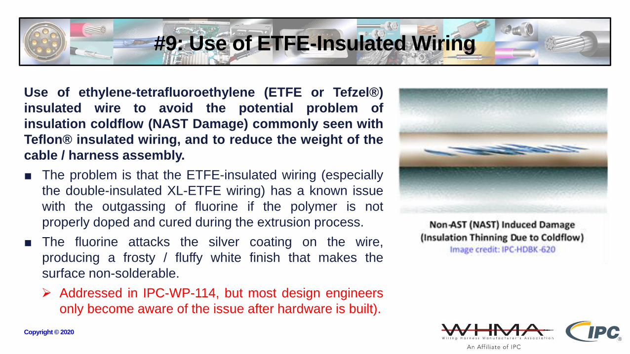
#9: Use of ETFE-Insulated Wiring
Use of ethylene-tetrafluoroethylene (ETFE or Tefzel®)
insulated wire to avoid the potential problem of
insulation coldflow (NAST Damage) commonly seen with
Teflon® insulated wiring, and to reduce the weight of the
cable / harness assembly.
■ The problem is that the ETFE-insulated wiring (especially
the double-insulated XL-ETFE wiring) has a known issue
with the outgassing of fluorine if the polymer is not
properly doped and cured during the extrusion process.
■ The fluorine attacks the silver coating on the wire,
producing a frosty / fluffy white finish that makes the
surface non-solderable.
➢ Addressed in IPC-WP-114, but most design engineers
only become aware of the issue after hardware is built).
Copyright © 2020

#10: Other Issues
Other issues include:
■ The lack of proper power derating analysis to account for thermal issues and voltage drop.
➢ Not taken seriously until the test integration team determines that the voltage drop in the
harness wiring is preventing sufficient power to ensure reliable operation from being delivered
to the next module.
■ The increasing disconnect between separate design activities involved in the design and
manufacture of wiring harnesses that must interconnect (e.g., there is often very little systems
engineering oversight).
➢ Doesn’t seem to be taken seriously until you try to mate a harness assembly with 14 AWG
conductors and contacts to a harness with 18 AWG conductors and contacts.
■ The lack of effective communication between designers and manufacturers.
■ The expected evolution of cable and wiring harnesses into functional systems in their own right,
by integration of embedded components or modules, allowing the cable or harness assembly to
reactively adapt to changing load demands, and report status to supervisory systems.Copyright © 2020

#10: Other Issues (cont.)
■ The increasing integration of optical fiber into the harness
assembly (e.g., hybrid).
■ The increasing use of hyper-flex stranding designs.
■ The increasing use of Litz wire for extremely high power
applications.
■ The increasing use of multi-color wiring in wiring harnesses,
when use of a common insulation color would suffice and the
colors serve no technical purpose other than “they look
pretty”.
■ The increasing use of aluminum wiring.
■ The lack of awareness of IPC-D-620 and IPC-HDBK-620.
Copyright © 2020

Conclusions
■ While we are rapidly moving to the commercialization of space (especially vehicles and
hardware), what works down here on planet Earth doesn’t always work “up there”.
➢ Flying in space is easy – getting to space is hard!
➢ No “up” or “down” in microgravity. Heated air doesn’t “rise” in space, it just envelopes the
hardware.
- Convective cooling capability usually not unavailable in the habitable section of the vehicle –
even though that portion of the vehicle has air. Most flight equipment doesn’t have fans to cool.
➢ Minor odors from materials used in wiring and harness assembly become really annoying in
space. Even the smell of something getting hot causes great concern.
■ Use mating connectors from the same manufacturer, shell material, and plating.
➢ Having two MIL-38999 connectors from different manufacturers means they will mate (the
specification requires that they do) – but there may be issues (e.g., tolerance stack-up, hard
versus soft materials, differing platings, etc.).Copyright © 2020

Conclusions (cont.)
■ Standardize on a single color wiring insulation in harness builds whenever possible.
➢ Some harness designs require wire color-coding, especially if different wire sizes, voltages, or
critical function circuits are present, or if field service is anticipated - but most do not.
➢ Harnesses constructed with all nine wire insulation colors look pretty, but the electrons don’t
care what the insulation color is.
- Running out of a specific insulation color in the middle of the build either stops the build or
requires an Engineering Change Note (ECN) to allow the use of a different color. > $$$
- Standardization of wire insulation color reduces procurement, test, and storage cost. < $$$
■ Treat wiring, cables, and harnesses with the respect the technology deserves.
➢ Cables and wiring harnesses are often the most overlooked, ignored, and “taken for granted”
component in a design.
➢ Not just a “wire”. High quality cables and wiring harnesses are essential to the performance
and reliability of any electrical / electronic system.Copyright © 2020

Conclusions (cont.)
Finally –
As we advance the use of A.I. and robotics, the “box”
may still be considered a box with wires, cables, and
harness assemblies inside – but it may eventually look
and behave like a living organism.
It’s important that the wiring technology works as
intended, especially if our intent is to mimic the human
response and achieve a “human presence” in difficult
environments and demanding missions - either here on
Earth, in space, or on a different planet.
Copyright © 2020
Robonaut 2, a dexterous, humanoid astronaut helper, flew to the International Space Station aboard space
shuttle Discovery on the STS-133 mission. Although it only participated in operational tests, upgrades could
eventually allow the robot to realize its true purpose -- helping spacewalking astronauts with tasks outside the
space station.
Image Credit: NASA
http://www.nasa.gov/mission_pages/station/multimedia/robonaut_photos.html

Thank You For Listening
QUESTIONS?
Copyright © 2020