solar power for outer planets study - lunar and planetary ... · solar power for outer planets...
TRANSCRIPT
National Aeronautics and Space Administration 1www.nasa.gov
Solar Power for Outer Planets StudySolar Power for Outer Planets Study
Presentation to Outer Planets Assessment GroupNovember 8, 2007
Scott W. Benson/NASA Glenn Research Center
National Aeronautics and Space Administration
www.nasa.gov
National Aeronautics and Space Administration 2www.nasa.gov
Background & OutlineBackground & Outline
•
Alan Stern request: “…a quick look study for how we could extend the Juno and Rosetta 5 AU-class missions on solar arrays to enable solar array missions at Saturn (10 AU) and Uranus (20 AU)”
••
Study ProcessStudy Process••
Cell and Array Technology FindingsCell and Array Technology Findings
••
Power System SizingPower System Sizing••
Mission and System Integration StudiesMission and System Integration Studies
••
Technology PlanningTechnology Planning••
ConclusionsConclusions
National Aeronautics and Space Administration 3www.nasa.gov
••
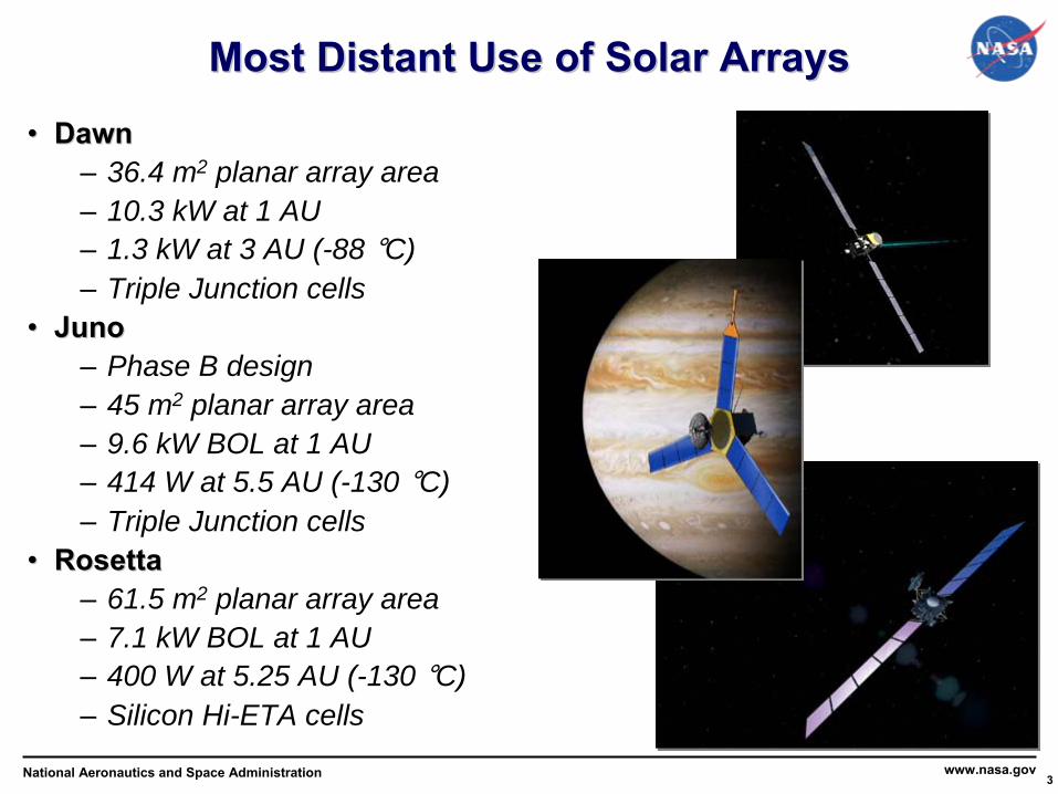
DawnDawn–
36.4 m2 planar array area–
10.3 kW at 1 AU–
1.3 kW at 3 AU (-88 °C)–
Triple Junction cells••
JunoJuno–
Phase B design–
45 m2 planar array area–
9.6 kW BOL at 1 AU–
414 W at 5.5 AU (-130 °C)–
Triple Junction cells••
RosettaRosetta–
61.5 m2 planar array area–
7.1 kW BOL at 1 AU–
400 W at 5.25 AU (-130 °C)–
Silicon Hi-ETA cells
Most Distant Use of Solar ArraysMost Distant Use of Solar Arrays

National Aeronautics and Space Administration 4www.nasa.gov
Study ProcessStudy Process
••
Review prior studies and flight system publicationsReview prior studies and flight system publications
••
Assess PV cell and array technologiesAssess PV cell and array technologies
••
Understand cell performance in outer planet applicationsUnderstand cell performance in outer planet applications
••
Analyze power system performanceAnalyze power system performance
••
Coordinate with technology, vendor and user community Coordinate with technology, vendor and user community through workshop at Space Photovoltaic Research & through workshop at Space Photovoltaic Research & Technology (SPRAT)Technology (SPRAT)
••
Coordinate with Juno projectCoordinate with Juno project
••
Characterize system integration considerationsCharacterize system integration considerations
••
Define technology pathsDefine technology paths

National Aeronautics and Space Administration 5www.nasa.gov
Solar Cell Technology FindingsSolar Cell Technology FindingsSolar Cell CapabilitySolar Cell Capability•
Nominal low intensity, low temperature (LILT) state-of-the-art (SOA) cell performance is viable at 5 AU and beyond
–
Cell efficiency increases with lower temperature but decreases with lower intensity
•
LILT Effect: off-nominal drop
in cell performance, must be mitigated to effectively use solar power in outer solar system
–
Understood and mitigated on earlier silicon cells–
Effect observed on SOA multi-junction (MJ) cells, cause not yet identifiedCell-to-cell variation
–
LILT Effect can be mitigated:Cell screening, optimization or advanced concentrator technology
•
On-going advances in cell technology can provide improvements–
NASA will need to adapt those to LILT conditions
GRC FY07 LILT IRAD testing results
Low Light Triple Junction Performance
18
20
22
24
26
28
30
32
34
36
-180 -160 -140 -120 -100 -80 -60 -40 -20 0 20 40Temperature (�C
1 AU
5.6 AU
22.1 AU
National Aeronautics and Space Administration 6www.nasa.gov
Applicable Technologies Applicable Technologies ––
Solar CellsSolar Cells••
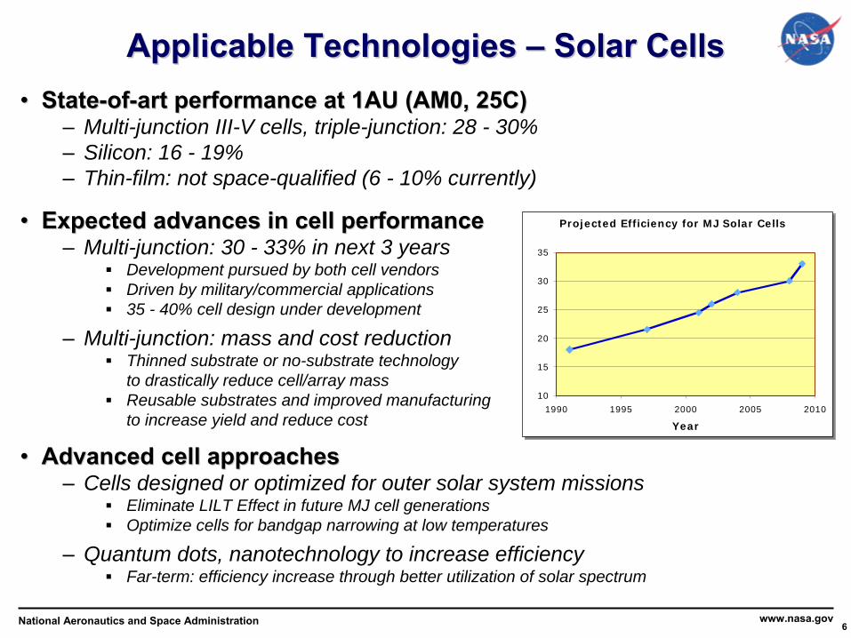
StateState--ofof--art performance at 1AU (AM0, 25C)art performance at 1AU (AM0, 25C)–
Multi-junction III-V cells, triple-junction: 28 - 30%–
Silicon: 16 - 19%–
Thin-film: not space-qualified (6 - 10% currently)
••
Expected advances in cell performanceExpected advances in cell performance–
Multi-junction: 30 - 33% in next 3 yearsDevelopment pursued by both cell vendorsDriven by military/commercial applications35 - 40% cell design under development
–
Multi-junction: mass and cost reductionThinned substrate or no-substrate technologyto drastically reduce cell/array massReusable substrates and improved manufacturing to increase yield and reduce cost
••
Advanced cell approachesAdvanced cell approaches–
Cells designed or optimized for outer solar system missionsEliminate LILT Effect in future MJ cell generationsOptimize cells for bandgap narrowing at low temperatures
–
Quantum dots, nanotechnology to increase efficiencyFar-term: efficiency increase through better utilization of solar spectrum
Projected Efficiency for MJ Solar Cells
10
15
20
25
30
35
1990 1995 2000 2005 2010
Year
Projected Efficiency for MJ Solar Cells
10
15
20
25
30
35
1990 1995 2000 2005 2010
Year
National Aeronautics and Space Administration 7www.nasa.gov
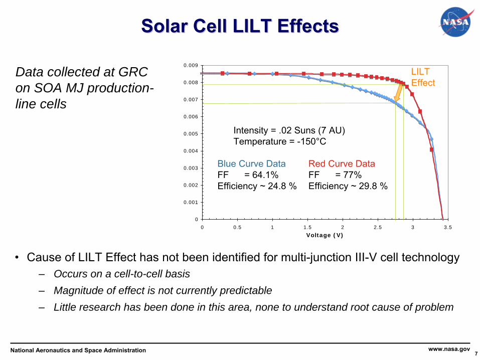
Solar Cell LILT EffectsSolar Cell LILT Effects
Data collected at GRC on SOA MJ production- line cells
•
Cause of LILT Effect has not been identified for multi-junction III-V
cell technology–
Occurs on a cell-to-cell basis–
Magnitude of effect is not currently predictable–
Little research has been done in this area, none to understand root cause of problem
0
0.001
0.002
0.003
0.004
0.005
0.006
0.007
0.008
0.009
0 0.5 1 1.5 2 2.5 3 3.5
Voltage (V)
Blue Curve DataFF = 64.1%Efficiency ~ 24.8 %
Red Curve DataFF = 77%Efficiency ~ 29.8 %
Intensity = .02 Suns (7 AU)Temperature = -150°C
LILT Effect

National Aeronautics and Space Administration 8www.nasa.gov
LILT Effect MitigationLILT Effect MitigationCell Screening•
Successful on Dawn
•
In progress for Juno
•
GRC and Juno data indicate that effect worsens in frequency and magnitude with lowering intensity
•
Cell screening may not be applicable beyond Jupiter
Cell Optimization•
Silicon cells designed
for LILT on Rosetta
–
5.2 AU, -130 °C
•
Future cells could be optimized–
To eliminate LILT Effect–
To optimize cell performance and mass for LILT conditions
Concentration•
Maintains
intensity
•
Minimizes
LILT Effect
•
Reduces cell
count
•
Increased spacecraft system
effects (pointing requirements)
Low Light Triple Junction Performance
18
20
22
24
26
28
30
32
34
36
-180 -160 -140 -120 -100 -80 -60 -40 -20 0 20 40Temperature (�C
1 AU
5.6 AU
22.1 AU
5% cell efficiency benefit at Saturn with 8X concentration
National Aeronautics and Space Administration 9www.nasa.gov
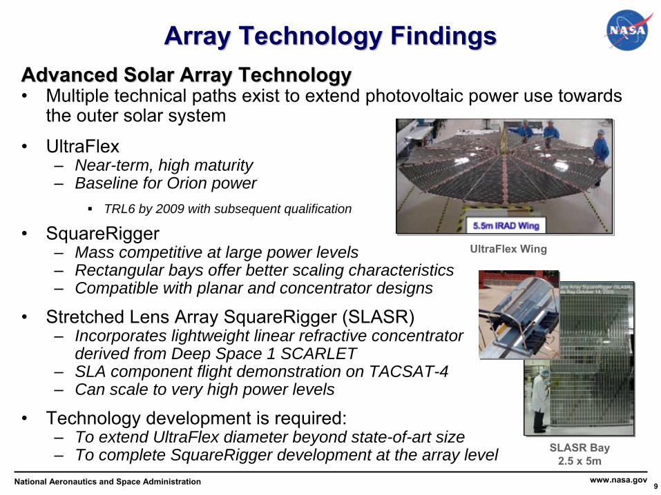
Array Technology FindingsArray Technology FindingsAdvanced Solar Array TechnologyAdvanced Solar Array Technology•
Multiple technical paths exist to extend photovoltaic power use towards the outer solar system
•
UltraFlex–
Near-term, high maturity–
Baseline for Orion powerTRL6 by 2009 with subsequent qualification
•
SquareRigger–
Mass competitive at large power levels–
Rectangular bays offer better scaling characteristics–
Compatible with planar and concentrator designs
•
Stretched Lens Array SquareRigger (SLASR)–
Incorporates lightweight linear refractive concentrator derived from Deep Space 1 SCARLET
–
SLA component flight demonstration on TACSAT-4–
Can scale to very high power levels
•
Technology development is required:–
To extend UltraFlex diameter beyond state-of-art size–
To complete SquareRigger development at the array level
UltraFlex
Wing
SLASR Bay2.5 x 5m

National Aeronautics and Space Administration 10www.nasa.gov
0100200300400500600700800900
1000110012001300140015001600170018001900200021002200230024002500
5 6 7 8 9 10 11 12 13 14 15 16 17 18 19 20
Distance (AU)
Pow
er (W
)
SLASR: 179 kg, 211m^2(~18bays)SLASR: 89 kg, 105m^2(~10bays)Four wing, 6 m diameter Ultraflex: 179 kg, 113 m^2Planar Squarerigger: 179 kg, 86m^2(~8bays)Two wing, 6 m diameter Ultraflex: 89 kg, 56 m^2Planar Squarerigger: 89 kg, 43m^2(~4bays)
Near Term Capability: Near Term Capability: Power from a Fixed Power System MassPower from a Fixed Power System Mass
•
Solar array options are sized to be the same mass as the two and
four wing Ultraflex arrays.
•
Solar array mass includes hardware outboard of gimbal•
SquareRigger standard bay size of 2.5 m by 5 m•
2.5 yr gravity assist period + 2 years at AU location + 2 AU/year transit time
•
Heliocentric space (no planetary radiation effects)
•
Useful power will be lower based on
planetary eclipses/ radiation degradation
•
SOA cell efficiency of 30% at 1 AU
•
LILT Effect-free cells
•
8X concentration with SLASR
*Juno-
SOA cells-
planar array-
mass not normalized
National Aeronautics and Space Administration 11www.nasa.gov
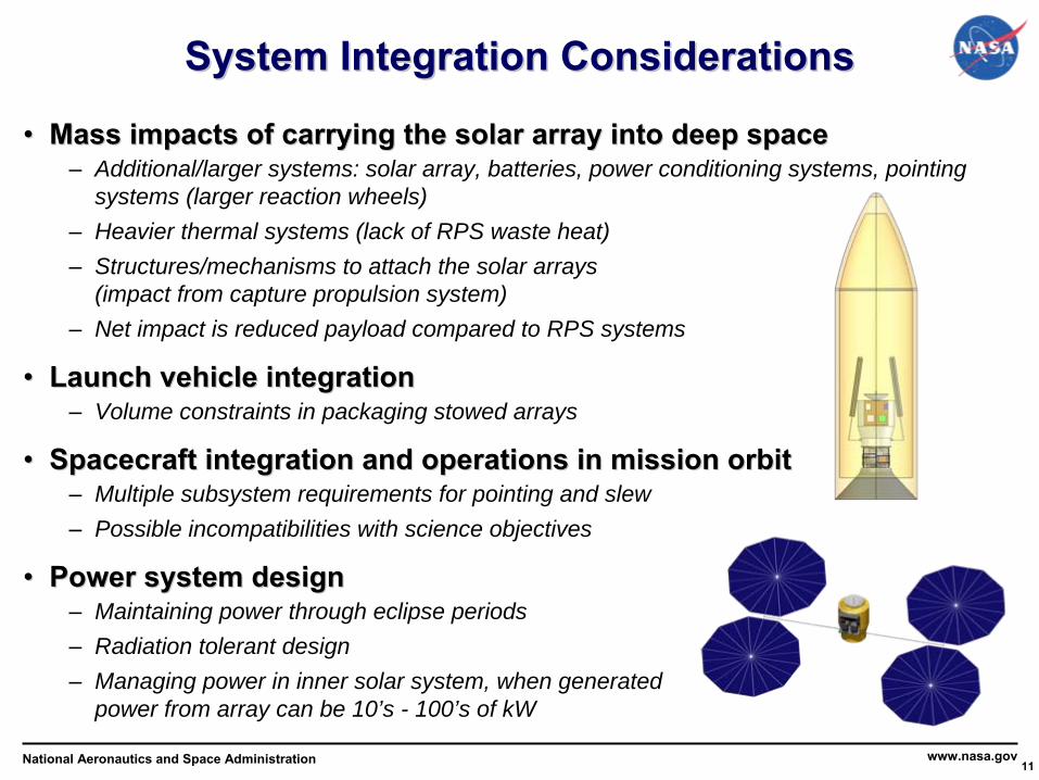
System Integration ConsiderationsSystem Integration Considerations
••
Mass impacts of carrying the solar array into deep spaceMass impacts of carrying the solar array into deep space–
Additional/larger systems: solar array, batteries, power conditioning systems, pointing systems (larger reaction wheels)
–
Heavier thermal systems (lack of RPS waste heat)–
Structures/mechanisms to attach the solar arrays (impact from capture propulsion system)
–
Net impact is reduced payload compared to RPS systems
••
Launch vehicle integrationLaunch vehicle integration–
Volume constraints in packaging stowed arrays
••
Spacecraft integration and operations in mission orbitSpacecraft integration and operations in mission orbit–
Multiple subsystem requirements for pointing and slew–
Possible incompatibilities with science objectives
••
Power system designPower system design–
Maintaining power through eclipse periods–
Radiation tolerant design–
Managing power in inner solar system, when generated power from array can be 10’s - 100’s of kW
National Aeronautics and Space Administration 12www.nasa.gov
Mission ApplicationsMission Applications
••
A range of missions were considered to encompass power system siA range of missions were considered to encompass power system sizing zing and spacecraft integration drivers, including:and spacecraft integration drivers, including:––
Heliocentric distance: 5 Heliocentric distance: 5 -- 20 AU20 AU––
Operations concept & power management: moon orbitersOperations concept & power management: moon orbiters––
Radiation: Radiation: JovianJovian moon orbitermoon orbiter––
Simplest missions: flybysSimplest missions: flybys
••
FlagshipFlagship--classclass–
Saturn Orbiter, Titan Orbiter–
Uranus Orbiter–
Ganymede or Europa Orbiter
••
PIPI--ledled–
Saturn Flyby–
Centaur Flyby or Rendezvous
••
Saturn Orbiter analyzed in COMPASS team studySaturn Orbiter analyzed in COMPASS team study–
Used GSFC Enceladus architecture option Saturn-OL as reference
••
EuropaEuropa, Centaur and Uranus missions assessed analytically, Centaur and Uranus missions assessed analytically–
Representative point analyses performed with selected mission power
National Aeronautics and Space Administration 13www.nasa.gov
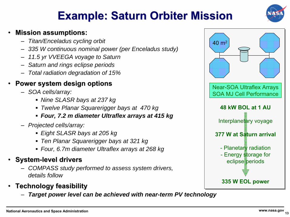
Example: Saturn Orbiter MissionExample: Saturn Orbiter Mission••
Mission assumptions:Mission assumptions:–
Titan/Enceladus cycling orbit–
335 W continuous nominal power (per Enceladus study)–
11.5 yr VVEEGA voyage to Saturn–
Saturn and rings eclipse periods–
Total radiation degradation of 15%
••
Power system design optionsPower system design options–
SOA cells/array: Nine SLASR bays at 237 kgTwelve Planar Squarerigger bays at 470 kgFour, 7.2 m diameter Ultraflex arrays at 415 kg
–
Projected cells/array:Eight SLASR bays at 205 kgTen Planar Squarerigger bays at 321 kgFour, 6.7m diameter Ultraflex arrays at 268 kg
••
SystemSystem--level driverslevel drivers–
COMPASS study performed to assess system drivers, details follow
••
Technology feasibilityTechnology feasibility–
Target power level can be achieved with near-term PV technology
Near-SOA Ultraflex
ArraysSOA MJ Cell Performance
48 kW BOL at 1 AU
Interplanetary voyage
377 W at Saturn arrival
-
Planetary radiation- Energy storage for
eclipse periods
335 W EOL power
40 m2

National Aeronautics and Space Administration 14www.nasa.gov
Other MissionsOther Missions
SystemSystem--level driverslevel drivers•
Radiation and eclipse power level•
Orbital operations and pointing requirements
Technology feasibilityTechnology feasibility•
SLASR and UltraFlex provide feasible paths
–
Four, 7.0 m diameter Ultraflex
arrays at 513 kg•
Requires detailed radiation degradation trade study
Advanced SLASR ArraysAdvanced SLASR ArraysSOA MJ Cell PerformanceSOA MJ Cell Performance
45 kW BOL at 1 AU, 362 kg
Interplanetary voyage
1400 W at Jupiter arrival
-
Planetary radiation, 30%
total degradation- Energy storage for
eclipse periods
720 W EOL at Europa
50 m2
Europa OrbiterEuropa Orbiter
SOA SOA Ultraflex Ultraflex ArraysArraysSOA MJ Cell PerformanceSOA MJ Cell Performance
33 kW BOL at 1 AU, 287 kg
Interplanetary voyage
300 W EOL at Echeclus
27 m2
SystemSystem--level driverslevel drivers•
Similar to Saturn Orbiter study
Technology feasibilityTechnology feasibility•
Target power level can be achieved with near-term PV technology
Advanced SLASR ArraysAdvanced SLASR ArraysProjected MJ Cell PerformanceProjected MJ Cell Performance
95 kW BOL at 1 AU, 327 kg
Interplanetary voyage
200 W EOL at Chiron
100 m2
Centaur: Centaur: EcheclusEcheclus Centaur: ChironCentaur: Chiron
SystemSystem--level driverslevel drivers•
Array size amplifies all spacecraft integration considerations
Technology feasibilityTechnology feasibility•
Technology is achievable•
Significant changes in spacecraft concept required
Advanced SLASR ArraysProjected MJ Cell Performance
232 kW BOL at 1 AU, 781 kg
Interplanetary voyage
400 W EOL at Uranus
250 m2
Uranus OrbiterUranus Orbiter
SystemSystem--level driverslevel drivers•
Array size amplifies all spacecraft integration considerations
Technology feasibilityTechnology feasibility•
Significant changes in spacecraft concept required
National Aeronautics and Space Administration 15www.nasa.gov
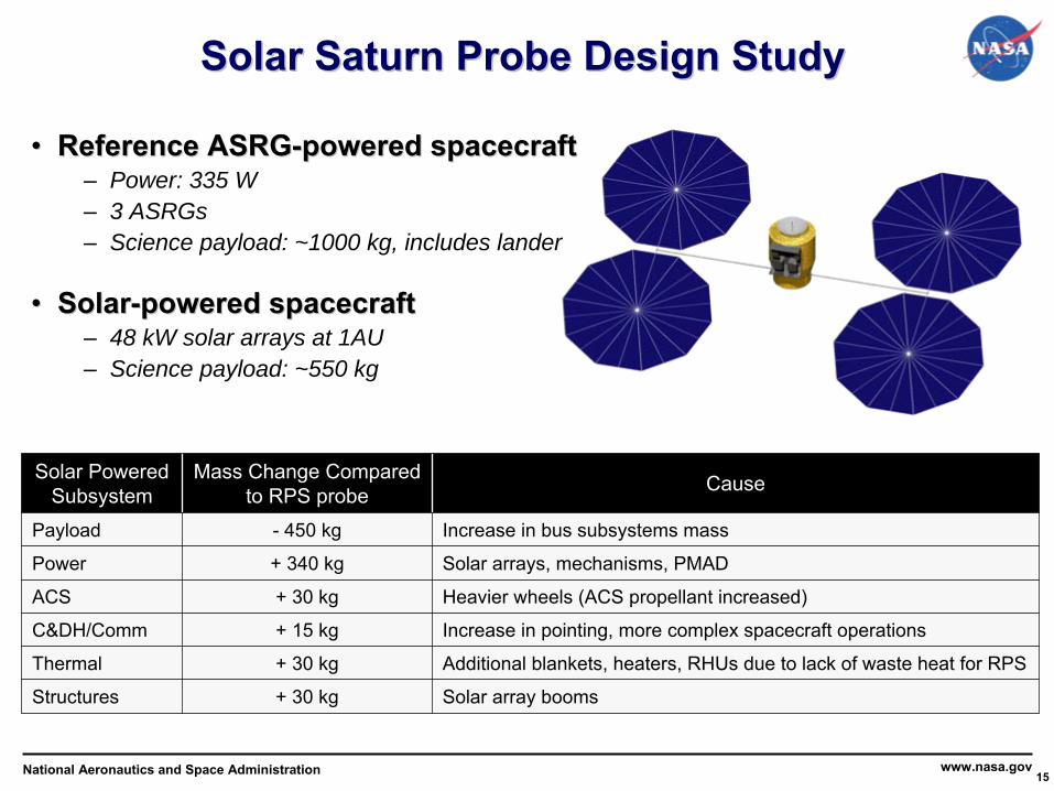
Solar Saturn Probe Design StudySolar Saturn Probe Design Study
••
Reference ASRGReference ASRG--powered spacecraftpowered spacecraft–
Power: 335 W–
3 ASRGs–
Science payload: ~1000 kg, includes lander
••
SolarSolar--powered spacecraftpowered spacecraft–
48 kW solar arrays at 1AU–
Science payload: ~550 kg
Solar Powered Subsystem
Mass Change Compared to RPS probe Cause
Payload -
450 kg Increase in bus subsystems mass
Power + 340 kg Solar arrays, mechanisms, PMAD
ACS + 30 kg Heavier wheels (ACS propellant increased)
C&DH/Comm + 15 kg Increase in pointing, more complex spacecraft operations
Thermal + 30 kg Additional blankets, heaters, RHUs
due to lack of waste heat for RPS
Structures + 30 kg Solar array booms
National Aeronautics and Space Administration 16www.nasa.gov
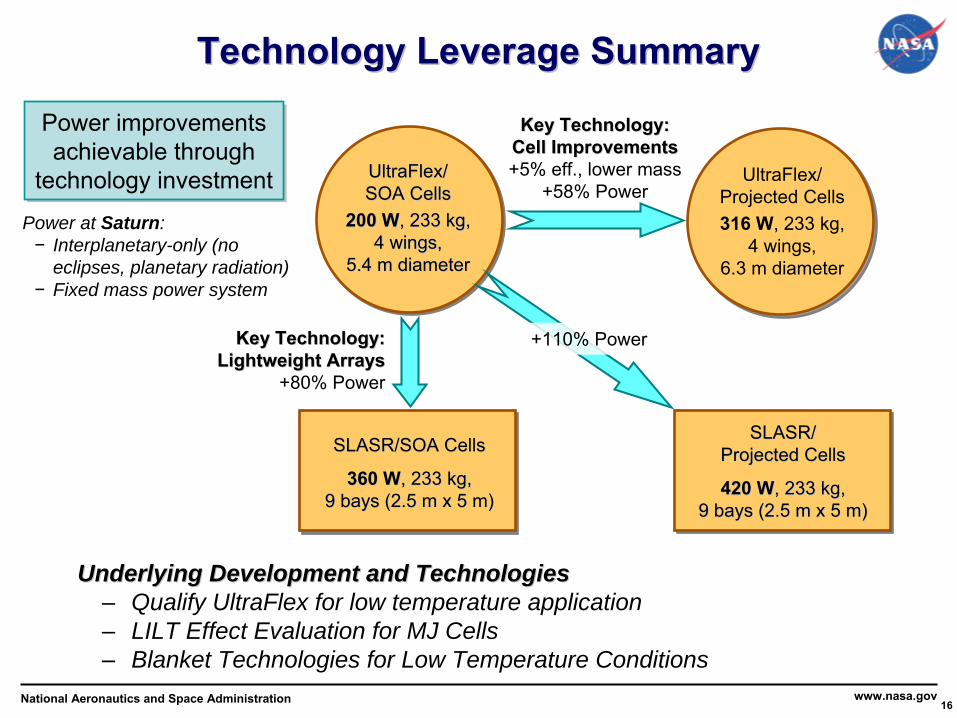
Power at Saturn:−
Interplanetary-only (no eclipses, planetary radiation)
−
Fixed mass power system
Key Technology:Key Technology:
Cell ImprovementsCell Improvements
+5% eff., lower mass
+58% Power
SLASR/SOA CellsSLASR/SOA Cells
360 W360 W, 233 kg, , 233 kg, 9 bays (2.5 m x 5 m)9 bays (2.5 m x 5 m)
SLASR/SLASR/
Projected CellsProjected Cells
420 W420 W, 233 kg, , 233 kg, 9 bays (2.5 m x 5 m)9 bays (2.5 m x 5 m)
Key Technology:Key Technology:
Lightweight ArraysLightweight Arrays
+80% Power
+110% Power
Power improvements achievable through
technology investment
Power improvements achievable through
technology investment
Technology Leverage Summary Technology Leverage Summary
Underlying Development and TechnologiesUnderlying Development and Technologies–
Qualify UltraFlex for low temperature application–
LILT Effect Evaluation for MJ Cells–
Blanket Technologies for Low Temperature Conditions
UltraFlexUltraFlex/ / SOA CellsSOA Cells
200 W200 W, 233 kg, , 233 kg, 4 4 wings, wings,
5.5.4 m diameter4 m diameter
UltraFlex/
Projected Cells316 W, 233 kg,
4 wings,
6.3 m diameter
National Aeronautics and Space Administration 17www.nasa.gov
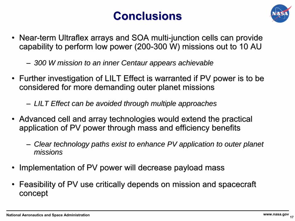
ConclusionsConclusions
••
NearNear--term term UltraflexUltraflex
arrays and SOA multiarrays and SOA multi--junction cells can provide junction cells can provide capability to perform low power (200capability to perform low power (200--300 W) missions out to 10 AU300 W) missions out to 10 AU
––
300 W mission to an inner Centaur appears achievable300 W mission to an inner Centaur appears achievable
••
Further investigation of LILT Effect is warranted if PV power isFurther investigation of LILT Effect is warranted if PV power is
to be to be considered for more demanding outer planet missionsconsidered for more demanding outer planet missions
––
LILT Effect can be avoided through multiple approachesLILT Effect can be avoided through multiple approaches
••
Advanced cell and array technologies would extend the practical Advanced cell and array technologies would extend the practical application of PV power through mass and efficiency benefitsapplication of PV power through mass and efficiency benefits
––
Clear technology paths exist to enhance PV application to outer Clear technology paths exist to enhance PV application to outer planet planet missionsmissions
••
Implementation of PV power will decrease payload massImplementation of PV power will decrease payload mass
••
Feasibility of PV use critically depends on mission and spacecraFeasibility of PV use critically depends on mission and spacecraft ft conceptconcept