solar drum positioner mechanisms * by l. w. briggs … · by l. w. briggs hughes aircraft company...
TRANSCRIPT

SOLAR DRUM POSITIONER MECHANISMS *
By L. W. Briggs
Hughes Aircraft Company
ABSTRACT
The need for additional power on spinning satellites has required development of deployable solar arrays activated, as on a 3-axis vehicle, after separation from a booster or shuttle orbiter. Mechanisms have been developed at Hughes for telescopically extending a secondary 36.3-kg (80-pound), 2.13-m (84-inch) diameter spinning solar drum for a distance of 2.0 m (80 inches) or more along the spin axis. After extension, the system has the capability of dynamically controlling the drum tilt angle about the spin axis to provide precision in-orbit balancing of the spacecraft.
This approach has been selected for the SBS, ANIK C, ANIK D, WESTAR B and PALAPA B satellites. It has been successfully demonstrated during the in-orbit deployment of the aft solar panels of the SBS F-3 and F-l satellites, subsequent to the November 1980 and September 1981 launches.
INTRODUCTION -_---____-
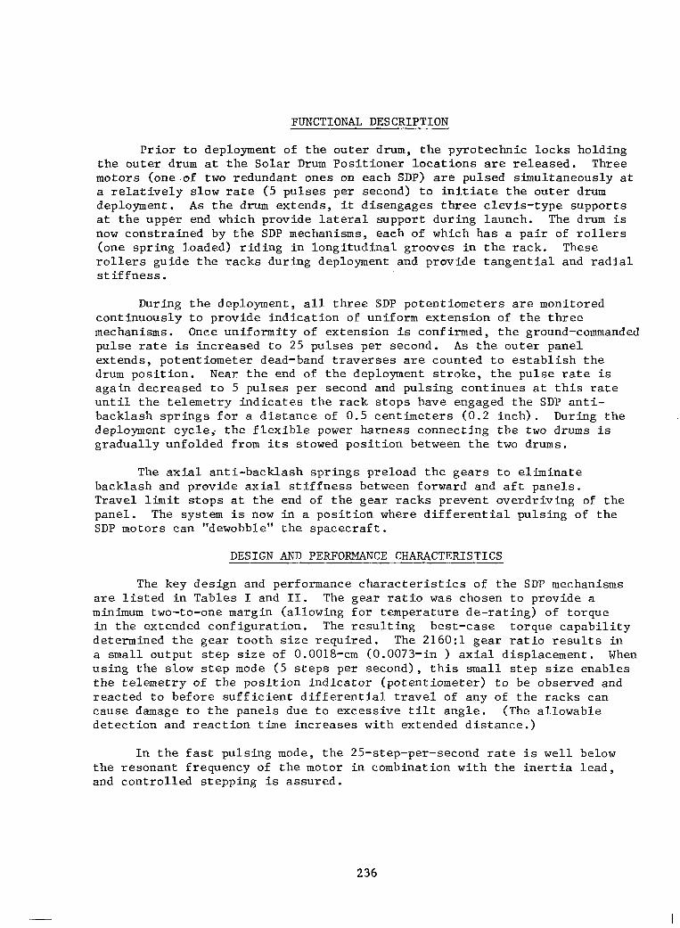
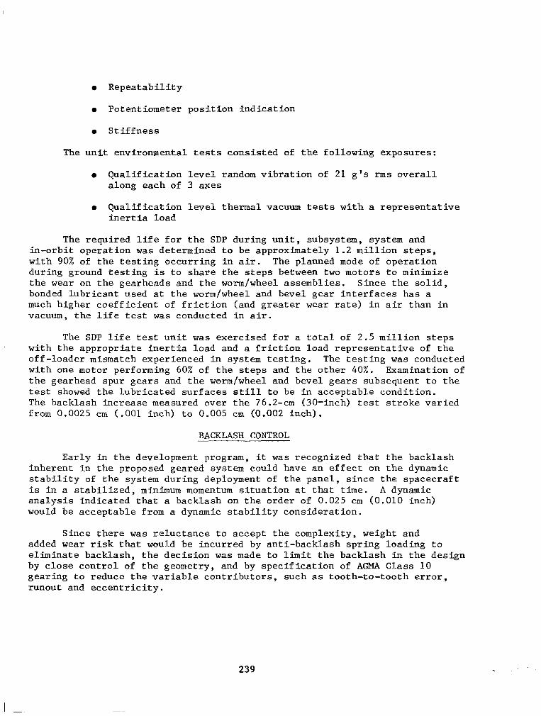
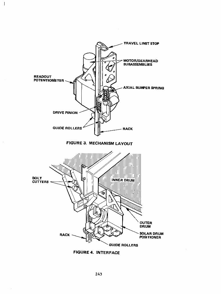
The Hughes HS 376 series of spacecraft utilize deployable, telescoping solar panel drums (see Figure 1) to enhance the on-board power capability. During launch and transfer orbit, the aft (outer) solar drum in its stowed position fits over the forward (inner) solar panel. During the drift orbit, the aft solar drum is extended by the operation of three Solar Drum Positioner (SDP) mechanisms. The mechanisms are located 120 degrees apart at the aft end of the inner solar panel (see Figure 2) with their output pinions engaging three longitudinal gear racks, mounted to the inner surface of the aft (outer) solar panel drum (see Figures 3 and 4). At full extension, each rack is driven into an axial anti-backlash spring located on the SDP. Differential operation of the SDP is then used to tilt the outer drum to provide dynamic balancing of the spinning spacecraft.
Trade-off studies of devices for mechanization of the extension resulted in the selection of a rack-and-pinion system with a stepper motor drive which contains a unique approach to redundancy for the size 11 permanent-magnet stepper motor.
A significant development has been minimizing the backlash or dead zone in the design to insure dynamic control during deployment and controlled in-orbit balancing at the extended position.
* Developed under contracts to Satellite Business Systems (SBS) and Telesat, Canada (ANIK).
235
https://ntrs.nasa.gov/search.jsp?R=19820015486 2019-03-12T16:43:01+00:00Z
FUNCTIONAL DESCRIPTION
Prior to deployment of the outer drum, the pyrotechnic locks holding the outer drum at the Solar Drum Positioner locations are released. Three motors (one.of two redundant ones on each SDP) are pulsed simultaneously at a relatively slow rate (5 pulses per second) to initiate the outer drum deployment. As the drum extends, it disengages three clevis-type supports at the upper end which provide lateral support during launch. The drum is now constrained by the SDP mechanisms, each of which has a pair of rollers (one spring loaded) riding in longitudinal grooves in the rack. These rollers guide the racks during deployment and provide tangential and radial stiffness.
During the deployment, all three SDP potentiometers are monitored continuously to provide indication of uniform extension of the three mechanisms. Once uniformity of extension is confirmed, the ground-commanded pulse rate is increased to 25 pulses per second. As the outer panel extends, potentiometer dead-band traverses are counted to establish the drum position. Near the end of the deployment stroke, the pulse rate is again decreased to 5 pulses per second and pulsing continues at this rate until the telemetry indicates the rack stops have engaged the SDP anti- backlash springs for a distance of 0.5 centimeters (0.2 inch). During the deployment cycle; the flexible power harness connecting the two drums is gradually unfolded from its stowed position between the two drums.
The axial anti-backlash springs preload the gears to eliminate backlash and provide axial stiffness between forward and aft panels. Travel limit stops at the end of the gear racks prevent overdriving of the panel. The system is now in a position where differential pulsing of the SDP motors can "dewobble" the spacecraft.
DESIGN AND PERFORMANCE CHARACTERISTICS
The key design and performance characteristics of the SDP mechanisms are listed in Tables I and II. The gear ratio was chosen to provide a minimum two-to-one margin (allowing for temperature de-rating) of torque in the extended configuration. The resulting best-case torque capability determined the gear tooth size required. The 216O:l gear ratio results in a small output step size of 0.0018-cm (0.0073-in ) axial displacement. When using the slow step mode (5 steps per second), this small step size enables the telemetry of the position indicator (potentiometer) to be observed and reacted to before sufficient differential travel of any of the racks can cause damage to the panels due to excessive tilt angle. (The allowable detection and reaction time increases with extended distance.)
In the fast pulsing mode, the 25-step-per-second rate is well below the resonant frequency of the motor in combination with the inertia lead, and controlled stepping is assured.
236

MECHANISM DESIGN DESCRIPTION
Each Solar Drum Positioner Mechanism is comprised of redundant stepper motors, gearheads and worm and wheel sets driving into a common, bevel gear differential whose spider, or trunnion shaft, is keyed to a common output shaft and pinion gear. A redundant element potentiometer provides shaft position indication through the spacecraft telemetry. A set of integral guide rollers secure the gear rack mating with the output pinion, and an axial compression spring engages a stop incorporated at the end of the rack (see Figures 5 and 6). The differential drive provides gear train redundancy up to the output pinion without single-point failure.
The stepper motors are phase-switched, four-phase, permanent-magnet- type motors. Each motor is powered by 28-volt-dc (nominal) square-wave pulses, sequentially applied to the four motor windings.
Each motor is coupled to a gearhead of the same size 11 configuration. The gearhead has a four-stage spur gear drive, with a total reduction of 36:l. The output of the gearhead drives a worm/worm wheel gear stage which has a reduction of 3O:l. Each worm wheel is fastened to one side of the differen- tial drive system, which allows either motor or both to drive the output pinion (see Figures 7 and 8). The total reduction from the motor to the output pinion is 216O:l with a single motor in operation. A 5.1-cm (2-in) pitch diameter pinion meshes with the gear rack (mounted on the outer panel), A 90" step of the motor results in 0.0018-cm (0.00073-in) axial movement of the rack. The outer panel travels 2.1 meters (82.7 inches) for full deployment which corresponds to 13.16 revolutions of the output pinion.
A redundant element potentiometer is mounted to the housing opposite the pinion. The wiper of the potentiometer is pinned to the output shaft which directly couples the wiper to the output pinion. The conductive plastic base of the potentiometer has two resistive elements, each with a 10" dead band. The wiper fingers contact the elements such that the dead bands are 180' out of phase. Thus, an indication of output pinion position is pos- sible for the entire 360" of rotation. The dead bands of the potentiometer elements are set at 90" and 270" when the drum is in its fully stowed condi- tion, so that dead bands are not encountered at fully stowed and fully de- ployed positions.
Rack-and-pinion gear teeth have been designed to accommodate the tilt capability. The output pinion teeth are crowned, and the rack has added clearance at the top portion to allow for tilting.
237

BEARINGS AND LUBRICATION
All bearings supporting the worm/wheel gears and differential are preloaded angular contact type. Ground shims are provided to set the proper wavy spring preload forces. These bearings have Duroid 5813 retainers (a glass-filled Teflon/molybdenum-sulphide composite) and the balls and races are lubricated with sputtered MoS2. The motor and gearhead bearings also have Duroid 5813 retainers and are "run-in" in a controlled atmosphere to transfer MoS2 lubricant to the balls and races.
The small gearhead spur gears have a 2000-g-thick coating of ion plated lead and are "run-in" as a gearhead assembly in a controlled atmosphere. The remainder of the gears and the worm shaft are treated with a proprietary solid, bonded lubricant (MoS2). The bonded MoS2 is employed at the worm/wheel and bevel gear interfaces because of extensive previous experience with this lubricant in similar space applications where sliding friction occurs.
REDUNDANCY
The differential approach to mechanical redundancy is common to the Solar Drum Positioner mechanism and the Antenna Positioner Mechanism (Reported at the 13th Aerospace Mechanisms Symposium in April 1979).
The differential gear system permits either motor/gearhead/worm and wheel system to drive the output shaft. Any failure in these components is overcome by switching to the standby system, which is unpowered for normal operation. In case of a failure (bearing or bevel gear) in the differential, both motors can be energized simultaneously and will cause the entire differential to rotate as a common member to drive the output shaft. In this mode, the gear ratio is halved and the step size at the output is doubled. The output torque remains the same as for normal operation. Redundancy at the main shaft output bearing is achieved by applying a thin sputtered MoS2 film to the close-tolerance slip fits of bearing to shaft and bearing to housing. This creates, in effect, a journal bearing at these interfaces that allows operation if the output bearings fail.
QUALIFICATION/LIFE TESTS
The SDP was subjected to a design qualification test and a representa- tive life test.
The key parameters evaluated during the qualification tests included the following:
l Output force (see Figure 9)
s Step accuracy (see Figure 10)
238
l Repeatability
l Potentiometer position ?ndication
0 Stiffness
The unit environmental tests consisted of the following exposures:
l Qualification level random vibration of 21 g's rms overall along each of 3 axes
l Qualification level thermal vacuum tests with a representative inertia load
The required life for the SDP during unit, subsystem, system and in-orbit operation was determined to be approximately 1.2 million steps, with 90% of the testing occurring in air. The planned mode of operation during ground testing is to share the steps between two motors to minimize the wear on the gearheads and the worm/wheel assemblies. Since the solid, bonded lubricant used at the worm/wheel and bevel gear interfaces has a much higher coefficient of friction (and greater wear rate) in air than in vacuum, the life test was conducted in air.
The SDP life test unit was exercised for a total of 2.5 million steps with the appropriate inertia load and a friction load representative of the off-loader mismatch experienced in system testing. The testing was conducted with one motor performing 60% of the steps and the other 40%. Examination of the gearhead spur gears and the worm/wheel and bevel gears subsequent to the test showed the lubricated surfaces still to be in acceptable condition. The backlash increase measured over the 76.2-cm (30-inch) test stroke varied from 0.0025 cm (-001 inch) to 0.005 cm (0.002 inch).
BACKLASH CONTROL
Early in the development program, it was recognized that the backlash inherent in the proposed geared system could have an effect on the dynamic stability of the system during deployment of the panel, since the spacecraft is in a stabilized, minimum momentum situation at that time. A dynamic analysis indicated that a backlash on the order of 0.025 cm (0.010 inch) would be acceptable from a dynamic stability consideration.
Since there was reluctance to accept the complexity, weight and added wear risk that would be incurred by anti-backlash spring loading to eliminate backlash, the decision was made to limit the backlash in the design by close control of the geometry, and by specification of AGMA Class 10 gearing to reduce the variable contributors, such as tooth-to-tooth error, runout and eccentricity.
239

The major contributors to backlash in the system are the worm and worm gear interface, the bevel gear mating and, of course, the pinion-to- rack interface. The gearhead is a minimal contributor because of a 30 arc-minute backlash control and the 6O:l gear reduction downstream of the gearhead.
The three areas of concern all have a relatively heavy, bonded, solid lubricant applied. For the worm and worm gear sub-assembly, close dimension- al control is exercised on the center mounting bores in the housing and a special nominal center fixture is used to check the fit of these parts before and after the lube application and burnishing. The bevel gears are pre- assembled and precisely measured. Special machining cuts and shimming are then performed to establish minimum backlash without interference. The rack- and-pinion interface is adjusted at assembly of the SDP to the spacecraft and the fit is maintained by the spring-loaded guide roller assembly engaging the rack.
The above controls and operations are intended to reduce the backlash during deployment of the panel. At the extended position, engagement of the rack stop into the compression springs reduces the backlash to zero.
During the orbital deployment of the SBS F-3 and F-l SDP's, the effectiveness of the backlash control was demonstrated. Infrequent actions of the thruster active nutation control were consistent with other expected energy dissipators, and additional firings due to excessive SDP backlash did not take place.
CONCLUSIONS
The system described has operated very well on the two spacecraft launched to date. No evidence of perturbation due to stepping or backlash has been observed during monitoring of the spacecraft during deployment of the panels. The in-flight results demonstrated the effectiveness of the minimum backlash design as well as all other design features.
240

TABLE 1. DESIGN CHARACTERISTICS
PARAMETER
MOTOR SIZE AND TYPE
MOTOR TORQUE
GEARHEAD
WORM GEAR STAGE
DIFFERENTIAL
OUTPUT PINION
RACK
OUTPUT STEP SIZE
INPUT POWER
SDP WEIGHT
CHARACTERISTICS
SIZE 11, PERMANENT MAGNET, 90° STEPPER
72 GM-CM (1.0 OZ-IN 1 RUNNING
SPUR GEAR; 36:l REDUCTION
24 PITCH; 3O:l REDUCTION
32 PITCH BEVEL; 2:l EFFECTIVE REDUCTION
24 PITCH; 48 TEETH
24 PITCH; 20’ PRESSURE ANGLE
0.0018 CM (0.00073 IN ) AXIAL
15 W AT 28 VDC
1.72 KG (3.8 LB) EACH
TABLE 2. PERFORMANCE CHARACTERISTICS
PARAMETER PERFORMANCE -
DEPLOYMENT TRAVEL 2.1 M (82.7 IN 1
DEPLOYMENT RATE 0.046 CM/S (0.0183 IN/S 1 AT 25 STEPS/S
OUTPUT FORCE 133 N (30 LB) AXIAL PER MECHANISM
MECHANISM STIFFNESS >I751 N/CM (1000 LB/IN ) IN PRELOAD RANGE
BACKLASH <0.0178 CM (0.007 IN ) DURING DEPLOYMENT 0 EXTENDED
POTENTIOMETER RESOLUTION
STEPPING RATE EXTENSION TI LT
0.061 CM (0.024 IN 1 OF DRUM TRAVEL
5 TO 25 STEPS/S 5 STEPS/S
241
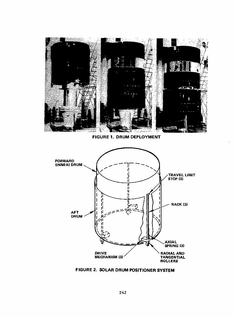
FIGURE 1. DRUM DEPLOYMENT
FORWARD (INNER) DRUM
AFT DRUM
RADIAL AND TANGENTIAL ROLLERS
FIGURE 2. SOLAR DRUM POSITIONER SYSTEM
242
TRAVEL LIMIT STOP
READOUT POTENTIOM’ETER
DRIVE
GUIDE
MOTOR/GEARHEA’D jj& SUBASSEMBLIES
AXIAL BUMPER SPRING
3LLERS - I IIL
FIGURE 3. MEC-HANISM LAYOUT
BOLT CUTTERS
OUTER DRUM
RACK SOLAR DRUM POSITIONER
’ GUIDE ROLLERS
FIGURE 4. INTERFACE
243

FIGURE 5. SOLAR DRUM POSITIONER NEAR SIDE
FIGURE 6. SOLAR DRUM POSITIONER FAR SIDE
244
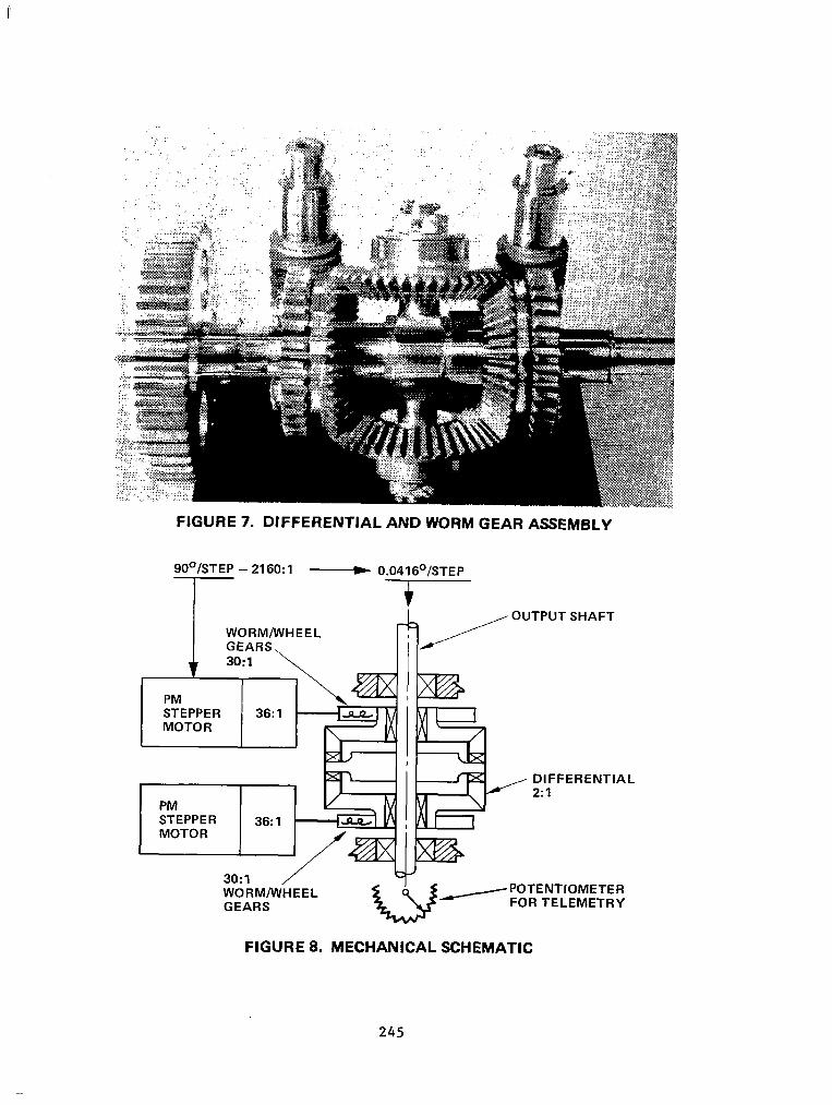
FIGURE 7. DIFFERENTIAL AND WORM GEAR ASSEMt3LY
900/STEP - 2160: 1 ___C 0.0416’lSTEP I
I WORM/WHEEL /OUTPUT SHAFT
PM IM
DIFFERENTIAL 2:l
STEPPER MOTOR
36:l 1-I n
3O:l /‘=J@+ WORM/WHEEL W /POTENTIOMETER GEARS FOR TELEMETRY
FIGURE 8. MECHANICAL SCHEMATIC
245

FIGURE 9. RACK TEST SECTION (FORCE OUTPljlT)
FIGURE 10. UNIT TEST FIXTURE
246

L. W. Briggs Hughes Aircraft Company P.O. Box 9219 Los Angeles, California 90009
Mr. Briggs is currently the senior project engineer in the Technology Division of the Space and Communications Group. He has 30 years' experience in the aerospace field involved in the design of electromechanical components for the Falcon, Phoenix, and Tow missiles; the Surveyor Moon Lander; and commercial and military satellites. During the last 12 years, he has been primarily con- cerned with the design and technical management of precision. positioning and gimballing subsystems for space. Mr. Briggs is a graduate of the Illinois Institute of Technology.
Mr. Briggs was co-author of a paper on the antenna positioner mechanism that was presented at the 13th Aerospace Mechanisms Symposium held at Johnson Space Center in April 1979.
247