software-defined networking and network … and without disrupting previous organizational...
TRANSCRIPT

© 2014 Cisco and/or its affiliates. All rights reserved. This document is Cisco Public Information. Page 1 of 22
White Paper
Authors
Mark “Mitch” Mitchiner
Solutions Architect
U.S. Federal Area
Reema Prasad
Solutions Architect
U.S. Federal Area
Software-Defined Networking and Network Programmability: Use Cases for Defense and Intelligence Communities
Abstract
This paper examines how recent advances in software-defined
networking (SDN) and network programmability can be used to
simplify operations, enhance agility, and meet new mission
requirements within U.S. Department of Defense (DoD) and
intelligence community networks. SDN and network programmability
have emerged to address trends in IT by providing greater automation
and orchestration of the network fabric, and by allowing dynamic,
application-led configuration of networks and services. To deliver
these requirements, networks must be open, programmable, and
application aware. Networks must evolve to meet these emerging
trends without compromising their current resiliency, service richness,
or security, and without disrupting previous organizational
investments.
This paper demonstrates, by means of use cases, how current networking issues within federal agencies, such as
the DoD and intelligence community, may be solved through SDN and network programmability.
Problem Statement
Introduction
Traditionally, network architectures within corporate and government networks use network devices that combine
control plane and data plane functions in a single device, typically a router or switch. The control plane is an
element of a router or switch that determines how one individual device within a network interacts with its
neighbors. Examples of control plane protocols are routing protocols, such as Open Shortest Path First (OSPF),
Border Gateway Protocol (BGP), and Spanning Tree Protocol (STP). These protocols determine the optimal port or
interface to forward packets (that is, the data plane). While these control plane protocols scale very well, and
provide a high level of network resiliency, they pose limitations. For example, routing protocols may only be able to
determine the best path through a network based on static metrics such as interface bandwidth or hop count.
Likewise, control plane protocols do not typically have any visibility into the applications running over the network,
or how the network may be affecting application performance.
Data plane functionality includes features such as quality of service (QoS), encryption, Network Address
Translation (NAT), and access control lists (ACLs). These features directly affect how a packet is forwarded,
including being dropped. However, many of these features are static in nature and determined by the fixed
configuration of the network device. There is typically no mechanism to modify the configuration of these features
based on the dynamic conditions of the network or its applications. Finally, configuration of these features is
typically done on a device-by-device basis, greatly limiting the scalability of applying the required functionality.

© 2014 Cisco and/or its affiliates. All rights reserved. This document is Cisco Public Information. Page 2 of 22
Figure 1. ONF Model for SDN
SDN and Network Programming Models
The Open Network Foundation (ONF) defines SDN as a decoupling of the control plane and the data plane.
Traditional network devices have an integrated control plane and data plane. In this classic SDN architecture,
however, network intelligence is logically centralized in a controller, and there is a physical separation between
control plane and the data plane. OpenFlow is the protocol that specifies the interactions between the control plane
running in the controller and the infrastructure (Figure 1). The intent of this architecture is agility, automation, and a
decrease in overall costs of the network.
While the classic SDN approach may hold promise for some customer
segments and use cases, it may not be the best fit for others, and is not
without its limitations. This complete separation of the entire control plane
from the data plane in a classic SDN model, removing it from the network
to a centralized controller, is a radical departure from the design and
operation of most networks today. The classic SDN approach to network
architecture introduces potential challenges in availability, performance,
scale, and security. When all control plane functionality is moved to a
central controller, the controller must be highly available. The performance
should meet the rapid requests and extreme load conditions on the
network. The controller must be able to scale to very large networks, with
thousands of nodes. Finally, it must be highly secure, with only approved
applications able to modify or change the underlying network.
While the classic SDN model takes advantage of network programmability,
SDN is not a requirement for programmability. Network devices can be
exposed to the application layer through application programming
interfaces (APIs). This hybrid approach to network programmability and
SDN deployments can take advantage of hardware intelligence as well as
existing feature sets within the network operating system. This can be
accomplished without a complete decoupling of the control plane and the
data plane (Figure 2). Moreover, in a classic SDN model, one must forgo
the features of the native operation system, as those capabilities must be
re-created in a controller. The hybrid SDN model allows many of the
benefits of a classic SDN model with a centralized controller, while still allowing users to benefit from the existing
network capabilities many have come to rely upon. In many cases, the network operating system can simply be
upgraded, rather than a complete upgrade of the network infrastructure. This allows an evolutionary approach to
network programmability, as opposed to the revolutionary approach of a classic SDN model. This evolutionary
method allows users to choose which applications and features are migrated out of the network device and onto a
controller or application server. Finally, a hybrid model allows users to use their existing fault management or
network management systems. The hybrid SDN model is able to minimize some of the potential challenges that
face a classic SDN approach to network architecture.

© 2014 Cisco and/or its affiliates. All rights reserved. This document is Cisco Public Information. Page 3 of 22
Figure 2. Hybrid SDN Model
Introduction of Cisco ONE and onePK
Overview
Cisco® Open Network Environment (ONE) is a comprehensive solution
that allows networks to become more open, programmable, and
application-aware. It is a portfolio of complementary technologies, which
includes platform APIs, controller and agent technologies, and overlay
network technologies. The platform APIs are a key element within the
Cisco ONE strategy and part of a Software Development Kit (SDK) called
ONE Platform Kit (onePK). onePK is a comprehensive set of platform
APIs, providing full-duplex programmatic access to Cisco devices. It is a
toolkit, which allows developers to build custom applications that interact
with Cisco network devices in ways that have never before been possible
(Figure 3). onePK enables developers to build automation and
orchestration into the network. The benefits of onePK can be achieved
through a software update to existing routers and switches, providing
investment protection and an evolutionary path to a software-defined
network.
Figure 3. The onePK Toolkit
onePK simplifies operations by allowing automation of functions, thereby creating efficiency. It provides a
framework for innovation, providing access to network devices, which allow new services to be created. Finally,
onePK increases agility by allowing new features and extending device functionality, allowing you to move faster.
The result is a rich interaction between applications and the underlying infrastructure.
The capabilities of onePK represent a hybrid SDN model. However, these capabilities may be used to facilitate the
construction of a classic SDN-based system. For example, onePK can be used to implement OpenFlow agents, or
be used by a network controller, each of which represents typical elements in a classic SDN architecture.

© 2014 Cisco and/or its affiliates. All rights reserved. This document is Cisco Public Information. Page 4 of 22
Cisco onePK Architecture
Cisco ONE Platform Kit is a development toolkit for major Cisco platforms. onePK is a highly flexible development
environment, providing a presentation API which supports C, Java, and Python languages (Figure 4).
Figure 4. The onePK Architecture
Central to the onePK architecture is a single set of API libraries for all Cisco major software platforms: Cisco IOS®
and Cisco IOS XE Software, Cisco IOS XR Software, and Cisco NX-OS Software. This infrastructure layer
provides a level of abstraction for platform-specific implementations. This helps ensure that the application
developer does not have to be concerned with the specifics of the network or underlying infrastructure, greatly
increasing the scope and scale of the application. Developers can use the same APIs across the entire network,
even when devices are running different network operating systems. It is this abstraction of the infrastructure that
greatly enhances the agility and time to market for the application developer.
Between the presentation and infrastructure layer is a communication channel, which provides a typical
client/server model between the application and the network device.
Deployment Models
A deployment model describes where the onePK applications will run. The applications can run on Cisco devices,
such as routers and switches, processing blades, or on an external server. Developers and network operators can
decide which model fits their mission and the requirements of the applications they are running. Each model is
source code portable. Discussed below are the three main deployment models.

© 2014 Cisco and/or its affiliates. All rights reserved. This document is Cisco Public Information. Page 5 of 22
Figure 5. Process Hosting Model
Figure 6 Blade Hosting Model
Figure 7. End-Node Hosting Model
Process Hosting
In the process hosting model, all onePK applications are run in a
process container directly on a Cisco network device such as a switch or
router (Figure 5). The supported containers are Linux containers (LXC)
and kernel-based virtual machine (KVM). The process hosting model
helps enable application developers to install and run applications within
a network element. This provides low-latency communication and a
single footprint for applications. Containerization helps ensure proper
resource allocation between each application.
Blade Hosting
In the blade hosting model, the applications are run on a process blade
(Figure 6). This helps enable an application to run close to the control
and data planes. This model means applications can have dedicated
resources to perform their tasks. The blade hosting model also provides
a high degree of isolation.
End-Node Hosting
In the end-node hosting model, applications are run
on an external server connected to the network
(Figure 7). This method gives users the flexibility to
use the platform of their choice. The platforms can
range from multicore Linux or Windows servers to
small mobile devices based on Android or iOS
operating systems. These platforms can run the
applications in either containers or on the host
operating systems, and they provide the highest
degree of isolation.

© 2014 Cisco and/or its affiliates. All rights reserved. This document is Cisco Public Information. Page 6 of 22
Security
The security model for onePK involves multiple security measures, which together help ensure that applications
are run highly securely, without introducing vulnerabilities to the network. Central to the security model, however, is
the network administrator, who plays a critical role in helping to ensure the security of the entire network. The
administrator authorizes which users can run which applications, and can enable onePK services for the entire
network or for specific users and devices. No applications can be run on network elements without the active
consent of the network administrator.
Authentication, authorization, and accounting (AAA) can also be enabled on the network devices. This helps
ensure that only authenticated and authorized users can run the application. Finally, the operations performed by
the applications on the network element may be logged through process accounting. This provides auditing of all
applications developed using onePK.
When applications are deployed to run in a containerized manner, the application developer has two options:
trusted containers and untrusted containers. Trusted containers are provided as part of the Cisco infrastructure to
run on network elements or processing blades. Trusted containers allow applications to use a private trusted
communications channel. Untrusted containers allow applications to run within commodity containers on servers.
Programmed applications are required to be authenticated and communicate using highly secure channels such as
Transport Layer Security (TLS). The network administrator can enforce that the application running from an
untrusted container has valid credentials to access the network element. Cisco recommends that all applications
be run in a container and that network administrators enforce resource limits.
In addition to deploying and running applications in a highly secure manner, the onePK security model provides
security measures for authenticity of the applications themselves. For example, the administrator can work to
ensure that a chain of trust exists between the developer of the application and the device it is installed upon. A
signature can be created by the publisher of the application package and verified during the time of install. It is up
to the network administrator to decide which application publishers are trusted. Finally, the internal interprocess
communication (IPC) mechanism performs strong type check and prevents buffer overrun conditions. Any IPC
access that originates from an untrusted host is authenticated and encrypted, using TLS-based security.
Use Cases
The power of SDN and network programmability is best illustrated through use cases. While there are a very large
number of potential use cases, here we focus on issues that face the DoD and intelligence communities in
particular, although enterprise companies may find them of value as well. Finally, the use cases explore and
highlight what is both reasonable and feasible, providing detailed examples and working code. While the code
snippets shown are in the C programming language, there is also feature parity with the Java and Python
languages. Please note that this is sample code and subject to change before the General Availability release of
the API.
Use Case 1: Latency-Based Routing
The goal of a routing protocol, such as BGP, OSPF, Intermediate System-to-Intermediate System (IS-IS), or
Enhanced Interior Gateway Routing Protocol (EIGRP), is to find an optimal path to a given destination within the
network. The metric used to determine the optimal path, however, is often fixed and static, and does not vary
based on the load placed on the network or the utilization of its links. For example, in the case of OSPF or IS-IS,
the cost used to calculate the best path is the interface bandwidth, which is typically fixed. In the case of BGP,
while there are metrics that can be set by the administrator, the protocol, again, is relatively static in nature.

© 2014 Cisco and/or its affiliates. All rights reserved. This document is Cisco Public Information. Page 7 of 22
In an era where cloud computing, big data, and surging video traffic are becoming the norm, networks are reaching
a saturation point, and unable to keep up with demand. In some cases, a path through a network may become
oversubscribed, while an alternate path may be underutilized, or not used at all. Because network traffic tends to
be “bursty” in nature, utilization of a set of links may fluctuate greatly over time. Traditional routing protocols may
not be able to react efficiently to the dynamic nature of today’s networks. Figure 8 shows a path through a network,
from Los Angeles to New York. This path is fixed - the lowest cost is based upon the bandwidth of each interface.
The network is unable to take into account the load on each of its links.
Figure 8. Network Path Based on OSPF Metrics
What is required is a mechanism that can dynamically react to the latency and utilization of the network in real-
time. For example, as links on a router get congested, the latency for traffic along that path increases, caused by
queuing delays in interface egress buffers. Thus, latency can be used as a metric for each path within a network,
which allows for real-time response to oversubscribed links in a network. Applications that require minimal delay
and jitter, such as mission-critical real-time traffic or voice traffic, could take a low-latency path through the network,
while all other traffic (such as bulk and transactional data) could take a path derived from the underlying routing
protocol. This allows real-time application traffic to be directed over links with the lowest latency to the destination.

© 2014 Cisco and/or its affiliates. All rights reserved. This document is Cisco Public Information. Page 8 of 22
As shown in Figure 9, a latency-based metric follows a different path through the network: one that has the least
latency or that is currently experiencing less congestion. This allows real-time application traffic to follow a path
through the network that provides the optimal response times.
Figure 9. Network Path Based on Low-Latency Metrics
To help enable this solution, each node in the network discovers the topology of the network, and the set of links
interconnecting each device. Next, each node in the network samples the latency to each of its connected
neighbors, and the result is sent to an application server. That latency data is fed into Dijkstra’s algorithm to
determine the lowest cost path, where cost in this case is the latency measurements. From the output of Dijkstra’s
algorithm, a new set of routes can be applied to the network, routes that provide the shortest path tree based on
latency in the network. These routes are “overlaid” on top of the routes derived from the existing routing protocol.

© 2014 Cisco and/or its affiliates. All rights reserved. This document is Cisco Public Information. Page 9 of 22
Figure 10 show sample code of the creation of a local application route, which can then be applied to each node in
the network through onePK.
Figure 10. Sample Code - Creation of a Local Application Route
Routes that are applied to a network node are known as application routes, as they are derived and installed by
applications. The application server installs the set of application routes on each node in the network. Figure 11
shows the routing table from a node in the network with a set of application routes.
Figure 11. Application Routes (Truncated Output)

© 2014 Cisco and/or its affiliates. All rights reserved. This document is Cisco Public Information. Page 10 of 22
This example provides a solution for low-latency routing, by overlaying a low-latency path through the network over
an existing routed path. Route table stability can be increased by modifying the latency data collection and
averaging mechanisms, and by implementing route dampening to minimize route flapping and prevent sustained
route oscillations. This solution can provide a routing algorithm that is able to dynamically react to the delay and
utilization of the network in real time, providing low-latency paths through a network for mission-critical application
traffic. However, great care must be taken while implementing such a solution. This example of latency-based
routing does not provide the loop-avoidance and black-hole avoidance mechanisms of mature routing protocols.
Moreover, centralization of the control plane can lead to scalability issues as well as transient micro-loops. Finally,
this solution is not intended as a replacement for existing routing protocols, as they provide the highest level of
stability and scalability. This example does, however, demonstrate the potential capabilities available in a hybrid
SDN model, highlighting the augmentation of the control plane where a subset of control plane functionality is
placed in a centralized application server.
Use Case 2: Dynamic QoS
Quality of service (QoS) refers to the ability to prioritize some applications, users, or data flows, at the detriment of
other data. It is used to help guarantee a certain level of performance to an application. For example, voice over IP
(VoIP) traffic may be prioritized and provided a fixed guarantee for delay, jitter, or bandwidth. However, such
guarantees are statically assigned to a port or interface on a router or switch, which has a fixed port speed. For
example, on a 100 Mbps Fast Ethernet interface, there may be a fixed 10 Mbps guarantee for voice traffic.
There are cases, however, where the bandwidth on an interface is not fixed, but varies over time. Traditional radios
or modems provide fixed modulation, and the bandwidth on the connected interface is also fixed. Newer wireless or
microwave radios and satellite modems, however, may provide adaptive modulation and coding mechanism. With
this technology, changes due to fluctuating weather conditions, attenuation due to obstacles, or limited line-of-site
operations may cause signal degradation and inferior signal quality, resulting in a reduction in the available
bandwidth over the link (Figure 12).
Figure 12. Impact of Signal Strength on Bandwidth

© 2014 Cisco and/or its affiliates. All rights reserved. This document is Cisco Public Information. Page 11 of 22
This change in bandwidth is signaled to the connected router or switch, which in turn changes its interface
bandwidth. However, it is possible that the interface bandwidth may be decreased below the reserved bandwidth
for a traffic class in the QoS policy. For example, if 10 Mbps of bandwidth were reserved for VoIP traffic, it may be
possible for the interface bandwidth to drop below this level (Figure 13). The result is inconsistent behavior, often
resulting in the removal of the QoS policy from the interface altogether.
Figure 13. Dynamic Reduction in Interface Bandwidth
What is required is the ability to actively monitor the signaled interface bandwidth, and modify the QoS parameters
based on the current bandwidth available over that interface.
The onePK toolkit brings that ability, through programmatic interfaces to network devices. Through the onePK API,
the interface bandwidth can be monitored, and a different QoS policy can be applied to an interface in real time,
based on the thresholds determined by the mission requirements. This feedback loop of monitoring the interface
and applying a QoS policy is done purely through software and without user intervention.
Figure 14 shows an example of this. Here, the available bandwidth over the wireless link drops to 5 Mbps, which is
signaled to the router interface. The onePK process on the router detects this change in bandwidth, and notifies the
onePK process running on a server. The server, based upon user-defined thresholds for interface bandwidth,
sends back a new QoS policy, which is applied to the router interface connected to the wireless modem. While an
external server is shown here, any of the three hosting models could be applied to this scenario.
Figure 14. Adaptive QoS Policy Applied to Router

© 2014 Cisco and/or its affiliates. All rights reserved. This document is Cisco Public Information. Page 12 of 22
Figure 15 shows sample code of a QoS policy being applied to a router interface. An interface target is first
created, and then a predefined QoS policy is applied to that target.
Figure 15. Sample Code - Applying a QoS Policy to an Interface
This use case demonstrates the value of onePK and network programmability by showing how the network can
react to dynamic external conditions and modify its state based on those conditions. This use case, in particular,
shows how network policy is no longer static, but is able to react to the current conditions and state of the network.
Use Case 3: Diversion Networking
Cyber security threats have evolved over the past decade. Attackers are increasingly improving their approaches
with greater funding, plus attacks are increasingly innovative. Defense tools must also change and adapt to this
evolving landscape. While intrusion detection and malware detection systems are essential elements of an overall
network security strategy, it is not enough to modify policies or controls. The security paradigm must be focused on
the threats themselves, and have the ability to protect against both the sophistication of the attacks as well as
against the sheer number of new attack vectors.
The new network security model must be able to detect threats and remove malicious flows in the network in real
time. However, with the migration to high-bandwidth links such as 10 Gb and eventually 100 Gb in the LAN and
even the WAN or to the Internet, traditional security devices are unable to process this amount of data. What is
needed is the ability to divert a subset of the overall network traffic off the naturally routed or switched path to a
device that can both offload the processing of the diverted traffic and provide a deeper level of inspection or
analytics.

© 2014 Cisco and/or its affiliates. All rights reserved. This document is Cisco Public Information. Page 13 of 22
Figure 16 shows this model. A subset of the incoming traffic from the WAN or the Internet is diverted to an
inspection server. This diversion could be copies of the packet or the original packet itself. The subset of the traffic
that is diverted could be based upon source address, destination address, protocol, port number, TCP flags or
even a pattern or signature within the packet payload itself. Furthermore, the decision to divert traffic could be
automated and based upon predefined policies or triggers.
Figure 16. Diversion Networking
In the case of a copy of the data traffic, the original traffic flow still proceeds via its original path and a copy of the
packet is sent to the inspection server. In the case of a punt, the original flow is diverted or redirected to the
inspection server.
The inspection server is able to provide forensics or higher-level analytics of the traffic. Based on the results of that
inspection, the data flow could be either dropped, or sent back to its original path. Furthermore, the inspection
server could instruct the edge router to drop all subsequent packets in that flow. Finally, the data could be sent to a
long-term storage cluster for further post-hoc forensics.
Central to the concept of diversion networking is the fact that, unless the data is dropped, the sender or source of
the traffic has no way of knowing that the traffic flow has been diverted.

© 2014 Cisco and/or its affiliates. All rights reserved. This document is Cisco Public Information. Page 14 of 22
Figure 17 shows sample code of onePK’s DataPath Service Set (DPSS). DPSS provides application developers
hooks into the packet flow through a Cisco switch or router to extract packets from that flow. In this case, the
packet is diverted (that is, punted) from its routed path and sent to the application, based upon a predefined source
and destination IP addresses in an ACL. The application obtains relevant information about the packet, such as IP
version number, source and destination addresses and ports, and Layer 4 protocol. In this sample code, if the
packet is an IPv4 TCP packet, the Layer 4 payload is sent to a function which does additional processing of the
TCP payload, such as advanced malware detection or intrusion detection, based upon predefined signatures.
Figure 17. Sample Code - Packet Processing for Deep Packet Inspection
Based upon the results of the payload processing, the packet could be sent back from the application to the
original destination, or dropped.
This example shows how one can simply divert network traffic from its original path to an application, which both
offloads the processing from the router and provides a mechanism for deep packet inspection and analytics.

© 2014 Cisco and/or its affiliates. All rights reserved. This document is Cisco Public Information. Page 15 of 22
Use Case 4: Central Policy Management for Access Control Lists
An ACL is a mechanism by which traffic that is entering (inbound) or leaving (outbound) an interface on a router or
switch may be filtered. This traffic may be allowed or denied, based on the configuration of the ACL. ACLs in this
context are primarily used as a network security mechanism, in which traffic from a specific host or subnet is
blocked or dropped. While ACLs can be applied at many places in the network, they are most often installed on
either the WAN edge, which connects to a separate network or autonomous system, or to routers that connect
directly to the Internet itself. In these cases, ACLs applied to the network edge provide the first line of defense
against cyber attacks.
Installation of ACLs on network devices is often a manual process. A network operator moves from device to
device, installing what is often the exact same ACL (Figure 18). The number of devices can be in the hundreds,
and the size of the ACLs can be as large as 100,000 entries or larger.
Figure 18. Installation of ACLs on WAN or Internet Edge Devices
What is needed is a scalable approach to ACL management, where the ACL policy is centralized. Programmatic
interfaces through onePK allow direct programmatic access to network devices from a central server, allowing an
operator to run a single application and install an ACL on many devices simultaneously. This is shown in Figure 19.
Figure 19. Installation of ACLs from a Centralized Application Server

© 2014 Cisco and/or its affiliates. All rights reserved. This document is Cisco Public Information. Page 16 of 22
This approach simplifies operations, allows explicit error checking, and reduces the possibility of human-induced
errors in the process. The central policy management of ACLs also allows additional logic, such as ACL expiration
or time-of-day policies, to be applied. Finally, a centralized ACL policy allows the immediate blocking of malicious
data traffic from all the routers at network edge in real time, should a new threat be detected.
Sample code of installation of a preconfigured ACL on a set of routers is shown in Figure 20.
Figure 20. Sample Code - Applying an ACL on a Group of Routers
This use case demonstrates the power of onePK to simplify operations by automating functions to increase
efficiency.
Use Case 5: Call Admission Control in Multiple Security Domain Networks
VoIP and unified communications are a group of technologies which allow both voice and data traffic to run over a
single infrastructure. VoIP utilizes network bandwidth extremely efficiently, as packet switching is much more
effective than transmission over a circuit-switched network. For these reasons, VoIP can both reduce total network
and infrastructure costs, as well as circuit costs.
Networks, however, can support a limited number of voice calls at any given time. Real-time traffic such as voice
requires sufficient bandwidth, and voice quality may suffer because of latency, jitter, and loss. These constraints
are especially pronounced in tactical networks, where connections between two locations are over satellite links. In
these scenarios, WAN links are typically well below 10 Mbps. Because of this, the concept of Call Admission
Control (CAC) is typically used, which limits the number of simultaneous voice calls over a given link or portion of
the network. CAC prevents voice traffic oversubscription of WAN links. For real-time traffic such as voice, it is
better to deny network access under congestion conditions than to allow traffic onto the network which could be
dropped, resulting in poor voice quality.

© 2014 Cisco and/or its affiliates. All rights reserved. This document is Cisco Public Information. Page 17 of 22
Figure 21 demonstrates a simplified view of the concept of CAC in a tactical environment. In this example, the
network supports a total of 10 VoIP calls. When the eleventh call is attempted, it is rejected because the network is
at maximum voice (VoIP) capacity. That is, CAC works in the call set-up phase, and protects voice traffic from
other voice traffic. Should the network allow the eleventh call through the network, the voice quality and user
experience of all of the calls would suffer. CAC makes a decision based on whether the required network
resources are available to provide suitable QoS for the new call.
Figure 21. Call Admission Control in a Tactical Network
One common CAC mechanism is Resource Reservation Protocol (RSVP). RSVP is a signaling mechanism that is
designed to reserve resources across a network. This gives RSVP the unique advantage of not only providing CAC
for voice, but also helping to guarantee the QoS against changing network conditions for the duration of the call.
RSVP can be initiated by either hosts or routers, which can request specific QoS guarantees, such as bandwidth or
performance, for voice calls. RSVP is aware of the topology of the network because the RSVP reservation is end to
end and installed on every interface the call will traverse through the network.
The end-to-end nature of RSVP introduces a challenge in tactical networks. Tactical networks are often deployed
with multiple security domains or enclaves. Data within the enclave is unencrypted or “in the clear,” and each
enclave has a “secure” or plaintext (PT) router. Each enclave is protected by an IP Security (IPsec) VPN device
(IVD), which provides packet-based encryption at the IP layer. The IVD within an enclave encrypts packets
received from the PT router and forwards it to the destination IVD through a single “unsecure” or ciphertext (CT)
router. In this context, “secure” refers to routers within the encryption boundary of the IVD. “Unsecure” refers to
routers that are outside the encryption boundary, which carry only encrypted traffic but are outside the security
domain.

© 2014 Cisco and/or its affiliates. All rights reserved. This document is Cisco Public Information. Page 18 of 22
Within a particular enclave, the IVDs build VPN tunnels between themselves. Because the RSVP messages
originate from within each enclave on the secure or PT side (which then enters the VPN tunnel), the RSVP traffic is
hidden from the CT network. As such, each PT router has no knowledge of the number of calls (that is, the amount
of reserved bandwidth) the CT router is able to support. Figure 22 highlights the issue of RSVP over an encrypted
or ciphertext network, although only a single enclave is shown for illustrative purposes.
Figure 22. RSVP Messages Across a Ciphertext Network (Single Enclave Shown)
Because the RSVP messages are hidden from the ciphertext network, one must infer the state of the ciphertext
core from the PT routers. This environment is additionally challenging when multiple security enclaves are
connected to a single CT core.
To resolve this, the PT routers in each enclave may send probes across the ciphertext core in order to determine if
the CT network has enough bandwidth to support new calls. This solution utilizes Cisco IOS IP Service Level
Agreement (IP SLA), which is a Cisco IOS mechanism that is able to diagnose network suitability for real-time
traffic applications such as VoIP. IP SLA is able to proactively monitor VoIP quality levels across the ciphertext
network by calculating consistent voice quality scores (mean opinion scores or MOSs) between PT routers within
an enclave. That is, each PT router sends an IP SLA probe at a specified frequency. The response from those
probes allows each router to determine if the ciphertext network can support additional voice calls at an acceptable
quality level. Figure 23 highlights this process with three security enclaves.

© 2014 Cisco and/or its affiliates. All rights reserved. This document is Cisco Public Information. Page 19 of 22
Figure 23. IPSLA Probes from Multiple Security Enclaves Across the Ciphertext Network
Within each enclave, a onePK application running on a server within the enclave is signaled at the return of an IP
SLA probe with the MOS score that represents the voice quality along the end-to-end path. The application checks
the MOS value against a user-defined threshold, such as a MOS score of “3” or “fair.” If the value from the
response falls below this predefined threshold, the RSVP bandwidth defined on the PT router is reduced.
When a new call request comes into the communications manager, it sends a reservation request to the PT router.
In this case, the request is rejected with a bandwidth unavailable code. This helps to ensure that no new calls are
placed from within the enclave, protecting voice quality for all current calls. Figure 24 represents this process.
While an external server representing the end-node hosting model is shown here, a blade or process hosting
model within the PT router itself could be used.
Figure 24. Call Blocked Based on IP SLA Response Metric
© 2014 Cisco and/or its affiliates. All rights reserved. This document is Cisco Public Information. Page 20 of 22
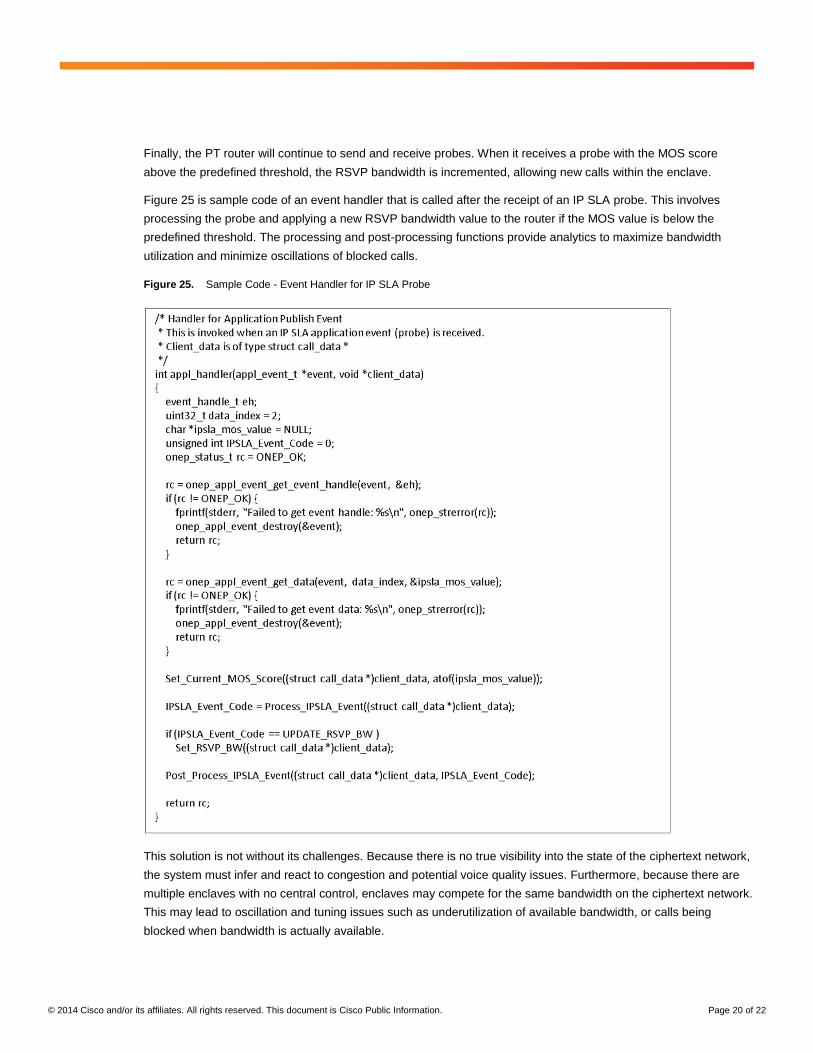
Finally, the PT router will continue to send and receive probes. When it receives a probe with the MOS score
above the predefined threshold, the RSVP bandwidth is incremented, allowing new calls within the enclave.
Figure 25 is sample code of an event handler that is called after the receipt of an IP SLA probe. This involves
processing the probe and applying a new RSVP bandwidth value to the router if the MOS value is below the
predefined threshold. The processing and post-processing functions provide analytics to maximize bandwidth
utilization and minimize oscillations of blocked calls.
Figure 25. Sample Code - Event Handler for IP SLA Probe
This solution is not without its challenges. Because there is no true visibility into the state of the ciphertext network,
the system must infer and react to congestion and potential voice quality issues. Furthermore, because there are
multiple enclaves with no central control, enclaves may compete for the same bandwidth on the ciphertext network.
This may lead to oscillation and tuning issues such as underutilization of available bandwidth, or calls being
blocked when bandwidth is actually available.

© 2014 Cisco and/or its affiliates. All rights reserved. This document is Cisco Public Information. Page 21 of 22
Regardless, there are several advantages to this solution. It is simple in design, and can be deployed without any
modification to the ciphertext network. Likewise, this solution can be implemented without the need for a network
guard, either between the secure and unsecure networks, or between the secure enclaves themselves. This
solution may also be deployed in many network topologies, such as ciphertext core architectures that provide load
sharing, because the probe traffic and voice bearer traffic follow the same path through the network. Finally, factors
such as probe frequency as well as averaging and hysteresis algorithms may minimize oscillations while providing
optimal bandwidth utilization. This use case demonstrates the ability of network programmability to react to
dynamic conditions within a network and modify the state of the network based on those conditions.
Conclusion
In the defense and intelligence communities, the network is mission-critical. Software-defined networking provides
a new architecture for this network, an architecture that brings the application layer and the networking layer closer
together. It is a shift in technology that will change the networking landscape by providing greater automation and
orchestration of the network fabric, and by allowing dynamic, application-led configuration of networks and
services. SDN allows the network to respond to requests from an application in real time, based upon the current
state and condition on the network. It is this agility which will transform networks as we know them.
With options for both classical and hybrid approaches to software-defined networking, you have a choice. By
introducing network intelligence in a centralized controller, the classical SDN model provides agility, automation,
and a decrease in costs. However, it poses challenges of high availability, scalability, and performance. The hybrid
SDN model minimizes some of these challenges by allowing you to choose which applications and features to
migrate to a central controller. The hybrid model continues to provide many of the benefits of the classical
approach to defense and intelligence communities.
Cisco’s approach to software-defined networking and network programmability is through the Cisco Open Network
Environment (ONE). This is an encompassing solution that allows network programmability and application
awareness. Programmability is achieved by exposing platform APIs to developers through the ONE platform kit
(onePK). The benefits of ONE and onePK include automation, orchestration, and customization of the network,
over an infrastructure layer that is abstracted from the platform. This, in turn, allows flexibility and simpler
management, both of which are key attributes of a mission-ready network.
The use cases described in this paper are examples of how SDN and onePK can provide benefits to defense and
intelligence networks. The use cases provide real-world examples as well as snippets of code, which developers
can use as guides when customizing their own networks. Developers can choose from the variety of examples and
decide which use case most closely matches their needs. Several different programming languages can be used,
providing flexibility of choice. In addition, because several different deployment models can be used, network
administrators have multiple options in incorporating SDN and network programmability into their environment.
Finally, network security is an integral part of the onePK solution, and operators can be confident that onePK can
be deployed, in a highly secure manner, into their current environment. Cisco’s approach to software-defined
networking and network programmability provides a path to a new architecture for defense and intelligence
communities.

© 2014 Cisco and/or its affiliates. All rights reserved. This document is Cisco Public Information. Page 22 of 22
References
● Open Networking Foundation:
http://www.opennetworking.org/
● Cisco Open Network Environment - An Overview:
http://www.cisco.com/en/US/prod/collateral/switches/ps9441/ps9902/white_paper_c11-728045.html
● Software-Defined Networking: Why We Like It and How We Are Building On It
http://www.cisco.com/web/strategy/docs/gov/cis13090_sdn_sled_white_paper.pdf
● ONE Platform Kit (onePK) for Developers:
http://www.cisco.com/en/US/prod/collateral/iosswrel/content/at_a_glance_c45-708540.pdf
● Resource Reservation Protocol (RSVP):
http://www.ietf.org/rfc/rfc2205.txt
● Deploying RSVP in Multiple Security Domains Networks: Securing Application Quality of Service
http://www.cisco.com/web/strategy/docs/gov/SecuringQOSwp_072508.pdf
● Cisco IOS IP Service Level Agreements (SLAs):
http://www.cisco.com/go/ipsla
● Cisco IOS Embedded Event Manager (EEM):
http://www.cisco.com/go/eem
Printed in USA C11-730834-00 01/14