software architecture for anti-submarine warfare … · iii approved for public release....
TRANSCRIPT

Calhoun: The NPS Institutional Archive
Theses and Dissertations Thesis and Dissertation Collection
2016-09
Software architecture for anti-submarine
warfare unmanned surface vehicles
Fahey, Stephen F., Jr.
Monterey, California: Naval Postgraduate School
http://hdl.handle.net/10945/50537

NAVAL POSTGRADUATE
SCHOOL MONTEREY, CALIFORNIA
THESIS
Approved for public release. Distribution is unlimited.
SOFTWARE ARCHITECTURE FOR ANTI-SUBMARINE WARFARE UNMANNED SURFACE VEHICLES
by
Stephen F. Fahey, Jr.
September 2016
Thesis Advisor: Luqi Second Reader: Winford Ellis

THIS PAGE INTENTIONALLY LEFT BLANK

i
REPORT DOCUMENTATION PAGE Form Approved OMB No. 0704–0188
Public reporting burden for this collection of information is estimated to average 1 hour per response, including the time for reviewing instruction, searching existing data sources, gathering and maintaining the data needed, and completing and reviewing the collection of information. Send comments regarding this burden estimate or any other aspect of this collection of information, including suggestions for reducing this burden, to Washington headquarters Services, Directorate for Information Operations and Reports, 1215 Jefferson Davis Highway, Suite 1204, Arlington, VA 22202-4302, and to the Office of Management and Budget, Paperwork Reduction Project (0704-0188) Washington, DC 20503.
1. AGENCY USE ONLY(Leave blank)
2. REPORT DATESeptember 2016
3. REPORT TYPE AND DATES COVEREDMaster’s thesis
4. TITLE AND SUBTITLESOFTWARE ARCHITECTURE FOR ANTI-SUBMARINE WARFARE UNMANNED SURFACE VEHICLES
5. FUNDING NUMBERS
6. AUTHOR(S) Stephen F. Fahey, Jr.
7. PERFORMING ORGANIZATION NAME(S) AND ADDRESS(ES)Naval Postgraduate School Monterey, CA 93943-5000
8. PERFORMINGORGANIZATION REPORT NUMBER
9. SPONSORING /MONITORING AGENCY NAME(S) ANDADDRESS(ES)
N/A
10. SPONSORING /MONITORING AGENCY REPORT NUMBER
11. SUPPLEMENTARY NOTES The views expressed in this thesis are those of the author and do not reflect theofficial policy or position of the Department of Defense or the U.S. Government. IRB Protocol number ____N/A____.
12a. DISTRIBUTION / AVAILABILITY STATEMENT Approved for public release. Distribution is unlimited.
12b. DISTRIBUTION CODE
13. ABSTRACT (maximum 200 words)
The U.S. Navy seeks to reduce costs associated with anti-submarine warfare (ASW) operations by exploring the use of unmanned surface vehicles (USVs). Currently, the process of finding submarines tends to be tedious and manpower intensive due to the high volume of acoustic data with limited means to filter for valuable information. Therefore, innovative software frameworks are required to transition from a “one-to-many” to a “many-to-one” USV/ human interaction model. By examining potential software frameworks, this thesis addresses many of the benefits and challenges inherent to using USVs in dynamic maritime environments. Furthermore, this evaluation provides a building block for the continued development of USV software systems.
14. SUBJECT TERMSUSV, ASW, autonomous systems, artificial intelligence, software architecture, unmanned systems
15. NUMBER OFPAGES
103
16. PRICE CODE
17. SECURITYCLASSIFICATION OF REPORT
Unclassified
18. SECURITYCLASSIFICATION OF THIS PAGE
Unclassified
19. SECURITYCLASSIFICATION OF ABSTRACT
Unclassified
20. LIMITATIONOF ABSTRACT
UU
NSN 7540–01-280-5500 Standard Form 298 (Rev. 2–89) Prescribed by ANSI Std. 239–18

ii
THIS PAGE INTENTIONALLY LEFT BLANK

iii
Approved for public release. Distribution is unlimited.
SOFTWARE ARCHITECTURE FOR ANTI-SUBMARINE WARFARE UNMANNED SURFACE VEHICLES
Stephen F. Fahey, Jr. Lieutenant, United States Navy
B.A., Virginia Tech, 2008
Submitted in partial fulfillment of the requirements for the degree of
MASTER OF SCIENCE IN COMPUTER SCIENCE
from the
NAVAL POSTGRADUATE SCHOOL September 2016
Approved by: Luqi Thesis Advisor
RADM Winford Ellis, USN (Ret) Second Reader
Peter J. Denning Chair, Department of Computer Science

iv
THIS PAGE INTENTIONALLY LEFT BLANK

v
ABSTRACT
The U.S. Navy seeks to reduce costs associated with anti-submarine warfare
(ASW) operations by exploring the use of unmanned surface vehicles (USVs). Currently,
the process of finding submarines tends to be tedious and manpower intensive due to the
high volume of acoustic data with limited means to filter for valuable information.
Therefore, innovative software frameworks are required to transition from a “one-to-
many” to a “many-to-one” USV/human interaction model. By examining potential
software frameworks, this thesis addresses many of the benefits and challenges inherent
to using USVs in dynamic maritime environments. Furthermore, this evaluation provides
a building block for the continued development of USV software systems.

vi
THIS PAGE INTENTIONALLY LEFT BLANK

vii
TABLE OF CONTENTS
I. INTRODUCTION..................................................................................................1 A. OVERVIEW / MOTIVATION .................................................................1 B. RESEARCH QUESTIONS .......................................................................1 C. LITERATURE REVIEW .........................................................................2 D. THESIS ORGANIZATION ......................................................................4
II. BACKGROUND ....................................................................................................5 A. THE SUBMARINE—A (VERY) BRIEF HISTORY .............................5
1. Purpose............................................................................................5 2. Operation ........................................................................................6
B. THE UNDERWATER ACOUSTIC ENVIRONMENT .........................7 1. Sound Waves ..................................................................................7 2. Speed of Sound ...............................................................................7 3. Sound Speed Profile (SSP) ............................................................8 4. Sound Propagation.........................................................................9 5. Sources of Noise............................................................................11 6. Deep Water versus Shallow Water .............................................12 7. Sound Channels ............................................................................12 8. Other Considerations...................................................................12
C. TOOLS OF THE TRADE .......................................................................13 1. Passive Sonar ................................................................................13 2. Active Sonar .................................................................................14 3. Non-Acoustics ...............................................................................15
D. GETTING THE MISSION DONE ........................................................16 1. Traditional Platforms ..................................................................16 2. New Platforms ..............................................................................17 3. The ASW Detect-to-Engage Sequence .......................................18
E. POTENTIALLY HOSTILE THREATS TO SURFACE VESSELS ..................................................................................................19 1. Diesel-Electric Submarines .........................................................19 2. Nuclear Powered Submarines .....................................................20 3. Submarine Weapons ....................................................................21
III. AUTONOMOUS SYSTEMS FOR ASW ...........................................................25 A. THE AGENT ............................................................................................25
1. Artificial Intelligence ...................................................................26 2. Rationality ....................................................................................26

viii
3. Sensors and Actuators .................................................................274. Perceptive Sequence .....................................................................275. Agent Functions ...........................................................................276. Agent Programs ...........................................................................28
B. THE ENVIRONMENT ...........................................................................28 C. THE PROBLEM ......................................................................................29
1. Protecting the Battle Group ........................................................292. Two Scenarios...............................................................................293. A Note on Complexity ..................................................................32
IV. DESIGNING A SOLUTION ...............................................................................35A. REQUIREMENTS ANALYSIS .............................................................35 B. ASSUMPTIONS .......................................................................................36 C. SETTING THE AUTOMATION BOUNDARY ...................................37 D. DESIGN AND ARCHITECTURE .........................................................38 E. AREAS FOR AUTOMATION ...............................................................39
1. Detection .......................................................................................392. Localization and Tracking ..........................................................403. Dynamic Event Notification ........................................................414. Contact Classification ..................................................................425. Signal Processing ..........................................................................426. Navigation .....................................................................................437. Formation Movement and Station Keeping ..............................44
F. THE USV MODULE ...............................................................................45 1. Hardware Interfaces ....................................................................472. Operating System .........................................................................473. Outgoing Communications .........................................................484. Incoming Communications .........................................................49
G. COMMAND AND CONTROL MODULE ...........................................49 1. Use Case ........................................................................................502. Vehicle Information Server (VIS) – (#2, Figure 6) ...................513. Sensor Stream Server (S2S) – (#3, Figure 6) .............................514. Data Server (DS) – (#4, Figure 6) ...............................................52
H. HUMAN/COMPUTER INTERFACE (HCI) MODULE .....................52 1. The “Safe” Ratio ..........................................................................532. Inspiration from Computer Gaming Industry ..........................533. Display Considerations ................................................................55
I. ASSESSING VALUE ..............................................................................56
ix
V. ADDITIONAL CONSIDERATIONS ................................................................59 A. SECURITY ...............................................................................................59
1. Cyber / Electronic ........................................................................592. Information / Data .......................................................................613. Communications (COMSEC) .....................................................644. Operational ...................................................................................655. Physical .........................................................................................66
B. MANPOWER ...........................................................................................68 C. TRUST ......................................................................................................70 D. MAINTENANCE AND UPKEEP ..........................................................71 E. ARGUMENTS AGAINST AUTOMATION .........................................72
VI. FUTURE WORKS AND RECOMMENDATIONS .........................................75A. FUTURE WORK .....................................................................................75
1. Operating in Fully Degraded CommunicationsEnvironments ...............................................................................75
2. Sense Making for ASW ...............................................................763. Classification Issues .....................................................................764. User Interface Prototyping and Use Study ................................765. Valuation Functions .....................................................................776. USV Group Leadership ...............................................................78
B. CLOSING .................................................................................................78
LIST OF REFERENCES ................................................................................................79
INITIAL DISTRIBUTION LIST ...................................................................................83

x
THIS PAGE INTENTIONALLY LEFT BLANK

xi
LIST OF FIGURES
Figure 1. Sound Speed (Velocity) Profile. Adapted from [9]. ....................................9
Figure 2. ASW Nomenclature. Source: [1]. ..............................................................30
Figure 3. Example of Maritime Shield. Source: [1]. .................................................31
Figure 4. Example of Protected Passage. Source: [1]. ..............................................32
Figure 5. Automation Boundary ................................................................................37
Figure 6. C2 and HCI Modules .................................................................................50
Figure 7. Data States .................................................................................................62

xii
THIS PAGE INTENTIONALLY LEFT BLANK

xiii
LIST OF TABLES
Table 1. Comparison of USV Capabilities and Limitations ....................................18
Table 2. ASW and Joint Operations Kill Chains Compared. Adapted from [16]. ............................................................................................................19

xiv
THIS PAGE INTENTIONALLY LEFT BLANK

xv
LIST OF ACRONYMS AND ABBREVIATIONS
AI artificial intelligence
ASW anti-submarine warfare
BB bottom bounce
BG battle group
CIEA Classification, Identification, and Engagement Area
C/COI critical/contact of interest
COLREGS IMO’s International Regulations for Preventing Collisions at Sea
CSG carrier strike group
CVW carrier air wing
CZ convergence zone
DICASS directional command activated sonobuoy system
DIFAR directional frequency analysis and recording
DP direct path
EO electro-optical
ESM electronic support measures
FLIR forward looking infrared
HSM helicopter maritime strike squadron
HVU/T high value unit/target
I/O input/output
IFF interrogate friend or foe
IMO International Maritime Organization
ISR intelligence, surveillance, and reconnaissance
LCS Littoral Combat Ship
MAD magnetic anomaly detector
MODLOC miscellaneous operating details, local operations
MPRA maritime patrol and reconnaissance aircraft
NVG night vision goggles
RADAR radio detection and ranging (depreciated)
ROE rules of engagement
SA surveillance area

xvi
SAG surface action group
SONAR sound navigation and ranging (depreciated)
SSP/SVP sound speed profile or sound velocity profile
SURTASS surveillance towed array sensor system
TTP tactics, techniques, and procedures
UMS unmanned system
USV unmanned surface vehicle
UxV unmanned unknown/undefined vehicle
VA vital area
WSM water space management

xvii
ACKNOWLEDGMENTS
I would like to thank my thesis advisor Dr. Luqi, for her guidance and patience,
and for granting me an unbelievable level of autonomy to, in the words of Ms. Frizzle
from the Magic School Bus, “take chances, make mistakes, and get messy.”
Additionally, I would like to thank Dr. Valdis Berzins for providing the guidance
in software development, LCDR Grant Garcia and CDR Rob Smith for offering their
grounding ASW influence, and RADM Jerry Ellis for serving as my sounding board on
ASW issues. I would also like to thank my fellow students and the NPS faculty for their
support and open discussions. Furthermore, I would like to thank my fellow
Bravo/Romeo pilots for your unique insights and candid responses to the changing nature
of ASW. I look forward to the next time we all may share a pint, until then—Sun Down,
LAMPS Up!
Finally, and most importantly, I would like to thank my beautiful little daughter,
Elise, for bringing a smile to Daddy’s face when he needed it, and to my wife, Debbie,
whose support, critical ideas, and discussions enabled me to be successful. Without her
support, I am not sure how I would have survived.

xviii
THIS PAGE INTENTIONALLY LEFT BLANK

1
I. INTRODUCTION
A. OVERVIEW / MOTIVATION
Autonomous systems appear to be in vogue, both in commercial and defense
sectors. News headlines capture the accomplishments and challenges faced by
autonomous systems every day. In this environment, the U.S. Navy seeks to better
understand this domain and how it can be apply knowledge gained to the problem of
making Anti-Submarine Warfare (ASW) less “dull, dirty, and/or dangerous” to human
operators.
Eliminating the adversary from the equation for a moment, it should be stated that
the maritime environment is a challenging domain for anyone who hopes to operate in it.
From time immemorial, mariners have been battling the effects of salt, water, wind, and
sun on machines, and the effects of distance and motion on people. No matter the
century, or the technology, these factors are constantly at work—to the detriment of the
mariner. It is then the challenge for an architect or designer to try to mitigate these forces,
and to ease the life of the people who put to sea. The notion applies equally as well to the
would-be engineer who is designing a system, hardware or software, to operate in this
domain. Then, to make the task even more challenging, add in the assumption that
someone else is trying to sink your design or halt your mission.
There is little published material on autonomous vehicle systems that operate on
the water’s surface in support of finding submarines hidden beneath. Additionally, there
is a lack of open discussion about software systems that could be used to control these
systems to make the jobs of the human operators easier.
B. RESEARCH QUESTIONS
This thesis sets out to answer the following questions:
What kinds of interactions will USVs need to have with other platforms in Maritime Shield and Protect Passage ASW and what degree of human operator control will they need?

2
Which aspects of these missions could the USVs carry out autonomously and what kind of autonomous decisions will be needed to carry out the missions more effectively than with current manned platforms?
How does one determine the value added by autonomy and decide which aspects of the USV mission would benefit most from automation?
C. LITERATURE REVIEW
The first job of any software architect is to understand the requirements of the
stakeholders. Sometimes these requirements are explicitly stated, but most of the time,
they are implied. However, being able to distill a customer’s requirements into a list of
bullets is not sufficient and is only the initial step. The next step is to actually begin the
design phase where the developer will attempt to craft solutions that meet the needs of
the customer. To aid in this process, the developer should become familiar with the
domain(s) that their solution is being designed for; in the case of this study, the domain is
ASW with USVs, which includes the maritime environment. To this end, it is instructive
to begin with a brief review of the literature that shaped the trajectory and understating of
the research domain.
In 2007, the U.S. Navy published its vision for future unmanned systems in [1],
which outlined the potential use of USVs in support of the ASW mission. In 2013, the
RAND Corporation took the idea further and suggested in [2] specific sub-categories of
ASW missions that a USV might perform well in. These two publications serve as the
launch pad for this research study.
To better understand the role of artificial intelligence in designing autonomous
systems, S. Russell and P. Norvig jointly authored a textbook [3] that covers many of the
fundamentals of modern AI. Additionally, the anthology of essays titled Human-Robot
Interactions in Future Military Operations and edited by M. Barnes and F. Jentsch
contains a number of essays that discuss human-robot interactions. The biggest takeaway
is in [4], which states a theoretically ideal mix of humans to robots for remote operations.
The term “robot” and “autonomous system” are often used synonymously, and for most
applications, the differences in terms are negligible. Many lessons that the field of
robotics has learned can easily be applied to the broader field of autonomous systems.

3
Furthermore, the book by B. Mishra titled Autonomous System: A Beginners Guide to
Design their Own Autonomous System from a Scratch discusses how to build an
autonomous system/robot from the ground up, the discussion on artificial neural nets
(ANN) influencing this project’s design. The anthology titled Autonomous Vehicles:
Intelligent Transport Systems and Smart Technologies addresses many topics on the
challenges of designing a hardware/software interface supporting autonomy.
From a more philosophical perspective, the paper by A. Bouchard and R. Tatum
titled “Verification of Autonomous Systems: Challenges of the Present and Areas for
Exploration” discusses a shift in the way of thinking about autonomous systems.
Specifically, they echo many industry leaders that say that Levels of Autonomy, as a
concept, is dead. They propose instead to see autonomous vehicles as a set of skills and
abilities. These two concepts form a lens in which to view the various functions of an
unmanned system (UMS).
In his 2007 master’s thesis [5], A. Oliveira outlines the software architecture for
an oceanographic research USV. The paper may be a little technical for a wider audience,
but many of the ideas he discusses are applicable to any future USVs. In his thesis, he
outlines the benefits to using a Linux based operating system (OS) over other operating
systems like Windows. Also, he recommends avoiding the use of threaded or multi-
threaded programs and instead recommends using single-thread/single process programs.
His reasoning is clearly outlined and served as an influence to my design.
Finally, Professor. Berzins’s class at NPS as well as the book [6] he co-wrote with
Professor Luqi proved invaluable to understanding the software architecture required by
autonomous systems. This was further augmented with R. Hanmar’s Pattern-Oriented
Software Architecture for Dummies, which discusses different approaches to designing
software, as well as E. Evans’s Domain-Driven Design: Tackling Complexity in the Heart
of Software, which talks about designing software in the context of a specific knowledge
domain like ASW. Both works proved to be valuable tools in channeling my vision for
the ASW USV’s software.
4
D. THESIS ORGANIZATION
The remainder of this document is organized in the following manner:
Chapter II is a primer on anti-submarine warfare distilled from the U.S. Navy’s
foremost-unclassified publication on acoustics known as the RP-33, with appropriate
context informed by my experience as a qualified aircraft and mission commander in the
Sikorsky SH-60B “Bravo” Seahawk multi-mission helicopter. In order to develop and
employ a useful USV, it is important to understand the environment it will operate in,
other systems that it will support and complement, and the threats it will attempt to detect
or defeat.
Chapter III focuses on introducing the reader to concepts in automation and
artificial intelligence (AI). The mere mention of AI conjures up ideas of cyborgs
attempting world domination; however, AI is really nothing more than very cleaver
programs that mimic certain human behaviors. AI is important when considering USVs
and ASW because it is difficult to “brute-force” detection of submarines and predict their
actions. Well thought out AI agents can help reduce the complexity of a situation and can
help focus a human on tasks that are more difficult for a computer to handle.
Chapter IV lays out a framework for the software architecture for an ASW USV.
This chapter discusses challenges, assumptions, and benefits to developing a software
system to handle multiple USVs.
Chapter V discusses critical though peripheral issues to the USV software
development. Finally, Chapter VI brings it together with concluding thoughts and
recommendations for future work.

5
II. BACKGROUND
Anti-Submarine Warfare is best thought of as both an art and a science. It is a
science because it is organized, systematic, based on proven research and theories, and,
for the most part, is largely repeatable. In order to further support this point, consider the
amount of knowledge, equipment, and training that is required to successfully conduct
operations in this environment. It is an art because even with dedicated study of all the
tactics, techniques, and procedures (TTPs) it is still a game of chance impacted by many
factors, with the enemy playing a significant role. In warfare it is said that the enemy
“gets a vote,” an observation of the reality that not all factors are knowable, and so one
must therefore be prepared for the unexpected. To inform later chapters, the following
sections attempt to set a baseline of understanding.
A. THE SUBMARINE—A (VERY) BRIEF HISTORY
The modern military submarine can trace its roots back to 1776 and David
Bushnell’s Turtle. It was intended to approach a ship unobserved, drill a hole in the
bottom of the hull, leave an explosive charge, and then evacuate before detonation. Due
to some critical design flaws, the plan failed, but the concept persisted as noted in [7].
The submarine gained prominence and notoriety during both of the previous World Wars
where the Germans used it to great affect at slowing, but not stopping, the stream of men
and material from the United States to its allies. Today, the submarine retains its historic
mission of striking commercial shipping and military targets, as well as performing long
range strike warfare and special operations.
1. Purpose
The main purpose of a Navy is power projection—both military and economic,
with its chief effort to ensure that the Sea-Lines-of-Communication (SLOC) remain open
for commerce and military movement. It is best to think of a SLOC as an imaginary line
that departs one country and traces a route to another location, along which people,
goods, services, and ideas may transit. To cut these routes, or to make them prohibitively
expensive, can have devastating consequences to those on both ends of the SLOC.

6
A submarine’s primary purpose is to disrupt the SLOCs by threating or destroying
shipping. When trade is disrupted, it can have severe consequences—locally, regionally,
and globally. For a more detailed history on submarines, consult [7].
2. Operation
A submarine is a stealth asset, capable of disappearing beneath the waves to strike
out at surface or sub-surface ships, launch long range missile strikes, conduct infiltration
operations, or to conduct espionage. Unlike surface ships, a sub cannot be easily
monitored or tracked, and so its intentions are usually unknown. This is what makes a sub
such a good deterrent—its ability to strike first without notice. Additionally, this
particular advantage is a major risk for an opponent and will usually result in the
submarine being a higher priority target for prosecution and neutralization.
According to Part II, Section 3, Article 20 of the United Nations Convention on
the Law of the Sea (UNCLOS), a submarine that is transiting innocently MUST do so on
the surface while showing their flag while in “Territorial Waters” [8]. This should be
interpreted as such: in failing to comply with these requirements, a submarine is
purposefully being evasive and is likely conducting operations that the coastal nation
would find aggressive or even hostile. This thought can be applied to the open ocean, or
“International Waters/High Seas,” to include the contiguous zones as well. If a submarine
wants to be “friendly” it will do so on the surface as this nullifies his advantages and
shows that he is not as much of a threat. Conversely, if a submarine is detected, and does
not surface to show good will, then it can be assumed that the submarine may have
ulterior motives, and needs to be treated with suspicion. Consider this analogy: while it
may be against the laws of some jurisdictions to wear masks or disguises, it is not fully
prohibited. However, when asked to remove said articles by a member of law
enforcement, and then an individual refuses to comply, and then their motives are
immediately questioned. Was their intent to be disguised in the commission of a crime, or
are they suspected of crimes and were trying to conceal their identity to avoid arrest?
This is a fundamental concept in ASW: if a submarine is trying to de-escalate
tensions, then they would do so on the surface, or would otherwise establish

7
communications. Failure to do so implies that they do not want to be found. This is why
searching for submarines is referred to as “hunting” and why there exists processes called
“kill chains” because like the criminal referred to above, the situation could turn
aggressive quickly, and friendly forces might be required to use deadly force to subdue
the would be assailant.
B. THE UNDERWATER ACOUSTIC ENVIRONMENT
The underwater acoustic environment is not a simple system, and entire books
have been written trying to capture the precise nature of this dynamic domain. The
following sections only include the very basics, and the dedicated scholar is encouraged
to seek further information with a recommended starting point being the Naval
Oceanographic Office’s (NAVOCEANO) Reference Publication 33, commonly referred
to in the ASW business as “The RP-33.”
1. Sound Waves
The RP-33 states, “Sound originates as a wave motion produced by a vibrating
source” that requires a medium like air or water for transmission. Sound waves have the
same properties as other waveforms (e.g., electromagnetic waves) such as frequency,
wavelength, amplitude, and speed. Sound will typically emit omnidirectionally from a
sound source, but it can be hard to visualize this phenomenon; therefore, it is easier to
think of sound as being a ray (like a light ray) being emitted from a source. If the medium
was uniform, then the sound ray would travel a straight path until it was reflected off
some surface. However, the ocean is far from uniform, and so sound has a tendency to
travel in curved paths [9].
2. Speed of Sound
The speed of sound in water is approximately 1500 m/sec, with changes in speed
being a function of water temperature, salinity, and pressure. These factors are highly
variable depending on geographic location, season, time of day and depth [9].
8
3. Sound Speed Profile (SSP)
The sound speed profile is a graphic representation of the speed of sound in
respect to temperature, depth (pressure), and to a lesser extent, salinity. See Figure 1. At
shallow depths (< 1500m), temperature plays the most significant role in affecting the
SSP. However, at approximately 1500m, temperature decreases slowly or becomes
isothermal for increasing depth, and yields to pressure for dominance in affecting the
SSP. Generally speaking, when the rate of temperature change is greater than the rate of
pressure change, then temperature will be the dominant factor on the SSP. Specifically, as
temperature decreases so too does the speed of sound. Conversely, when the rate of
pressure change is greater than the rate of temperature change, pressure will be the
dominant factor in calculating the SSP. Specifically, once the rate of temperature
decrease slows or halts, pressure becomes dominant and the speed of sound will increase.
A property known as depth excess, useful in predicting convergence zones (covered
later), will occur when the speed of sound increases back to where it initially began to
decrease. Salinity, for the most part, plays a minimal role in deep open-ocean
environments. This is because most of the world’s oceans tend to be close (+/- 2 ppt) to
the global average of 35 parts per thousand (ppt) of salt, so planners figure salinity to be
relatively static. This assumption is not valid in shallow water or polar environments
where the influx of fresh water may play a significant role on regional salinity [9].

9
Figure 1. Sound Speed (Velocity) Profile. Adapted from [9].
4. Sound Propagation
As soon as a sound is created, its behavior is subject to the peculiarities of the
medium it is being transmitted through. As previously mentioned, if the ocean were
uniform then sound would travel in straight lines, but because it is not uniform, sound
travels in seemingly curved paths. This is the result of refraction that is encapsulated in
Snell’s Law. The RP-33 defines Snell’s Law as “a ray going from a region with one
speed will have a different direction in a second region which has a different speed.” This
concept can be applied multiple times over multiple layers or regions of water that hold
uniform properties. It should be noted that, except in a vacuum, the refracted ray will
bend towards areas of lower sound speed [10]. Therefore, the general observation is that
sound generally travels away from areas that have a higher speed of sound, and will
travel towards areas that have slower sound speeds leading to the appearance that sound
travels in curved paths [9]. The basic mnemonic is higher away, lower towards.

10
a. Propagation Loss
As sound waves travel through the ocean, the pressure of the sound wave
diminishes, this is known as propagation loss. It is important to understand how pressure,
energy, and sound intensity interact because it impacts the detection process. The lower
the signal level, the harder it is to detect. The seven main factors that impact propagation
loss are losses due to: spreading, absorption, scattering, the bottom, the surface,
diffraction, and multi-path interference [9].
Spreading Loss: There are two main types of spreading loss, spherical and
cylindrical. Spherical spreading loss can be thought of as the ideal or theoretical model
for spreading loss where sound emits from a source in all directions without any
constraints. Cylindrical is closer to reality where you have an upper (surface) and lower
(bottom) boundary that contain sound energy. In the spherical model, sound intensity
decreases by 6dB per distance from the source doubled. Cylindrical loss is slightly better
at only a decrease of 3dB per distance doubled.
Absorption Loss: As a sound wave travels from its source, some of the
mechanical energy is converted into heat, which causes a loss of sound intensity.
Generally speaking, absorption is proportional to the square of the frequency [9]. This
means that lower frequencies will travel further, and higher frequencies will be absorbed
sooner.
Scattering Loss: Because a water column is not uniform and there will be many
variations of temperature and salinity even in a fairly uniform layer, some energy will be
refracted and reflected away from the main sound wave causing a general loss of
intensity [9].
Bottom and Surface Loss: These two types of loss are related in that they are the
result of the acoustic energy interacting with the edge of the medium (water). In the case
of the bottom, it is the composition of the ocean floor, and in the case of the surface loss,
it is wave action [9].
Multi-path Interference: As rays of sound depart a source in different directions,
they may eventually meet with one another. When these rays meet, they may either do so

11
constructively (increase in sound intensity) or destructively (decrease in sound intensity)
depending on the difference in the lengths of the two paths [9].
b. Propagation Paths
The RP-33 recognizes six different types of propagation paths. It is not necessary
to cover all of them. The most important of the propagation paths for ASW in and around
the battle group is direct path or “DP.” DP propagation is sound that has been emitted
directly from its source that travels an “approximately straight-line path between sender
and receiver” without being subject to signal loss or frequency shift due to interactions
with the bottom or surface. If you have DP contact, your vessel of interest is close. It is
also worth mentioning convergence zone or “CZ” propagation. When the ocean is deep
enough to have a depth excess, and is free of obstructions, sound can travel for a very
long distance. To give some perspective, the typical directional frequency analysis and
recording (DIFAR) sonobuoy deployed from aircraft has a relatively short detection
range of only a few thousand yards with DP contact. However, when CZs are possible
due to depth excess, detection ranges may extend 30 Kyds to 60 Kyds (15 to 30 NM). In
some regions, it is possible to have multiple CZs, so the true detection range could be
extended even further. For example, if your acoustic prediction software estimated CZ
contact to be possible out to four CZ, then one might be able to detect a submarine as far
as 60 to 120 NM away. Depending on the use, this contact can be more beneficial than
direct path as it provides the listener with advanced notice of an approaching submerged
vessel [9]. This works both ways though, and a submarine may be able to detect the
listener’s presence.
5. Sources of Noise
In ASW, as with many fields, it is important to separate signals from noise. To
recognize when one has a signal, one has to discriminate the noise. The RP-33 classifies
two types of noise: ambient and self. Ambient noise is that which is part of the
environment independent of the actions and movements of the search platform. Ambient
noise includes maritime traffic, melting/forming ice, biologics, and marine mammals.
Self-noise covers everything caused or related to the search platform; examples include
12
machinery noise, propeller noise, hydrodynamic noise, and aircraft noise. Self-noise can
interfere with the search platform’s instruments and give away the platform’s position to
an enemy [9].
6. Deep Water versus Shallow Water
In deep water, sound can travel a great distance before it is fully absorbed, which
can allow a careful listener to detect a submarine. However, to fully exploit some of these
properties requires sensors that can go deep enough to capture this information. When the
depth excess is greater than 200 fathoms (1200 ft.) then there exists a strong (>80%)
probability that CZ propagation is possible. Recall from the previous section that CZ
propagation can be detected 15–30 NM from the source, and multiple CZs may exist [9].
A noisy submarine in deep water is a submarine that wants to be found. Between shallow
and deep water, deep water is considered the easier environment. Shallow water is much
more sensitive to the effects of weather, geography/topology, and changing temperatures
and salinity. Additionally, to complicate matters, shallow water also contains the highest
density of maritime traffic, which means that there is a lot of noise in the water. Passive
sensors become useless in shallow water environments because of the low Signal to
Noise (S/N) ratio, so ASW operators favor active sonar and non-acoustic sensors there.
7. Sound Channels
In deep and shallow water, acoustic channels can form that essentially trap sound
inside the channels. These channels can help propagate sound waves over very long
distances and help relay a submarines location to a search vessel, but a crafty submarine
masking its activities from prying hydrophones can also use them [9].
8. Other Considerations
The previously listed topics are by no means an exhaustive list of considerations.
Some of the other major factors include: bottom composition (sand, clay, etc.), topology
(sea mounts, pinnacles, trenches), and upslope/downslope effects. Bottom topology is
important because it can impact the intensity of acoustic signals through absorption and
scattering. For example, soft silt or clay bottoms will tend to attenuate sound while hard

13
bottoms like rough rock will tend to reflect sound. By way of a common example,
imagine talking in an enclosed room that is carpeted and then image the same room with
a hard-wood floor. Topographical features, such as pinnacles, can reflect sound in ways
that may be misinterpreted as submerged vessels. Further, the slope of the continental
shelf can act like a megaphone, channeling sound from shallow water source to a receiver
in deep water, thereby exposing a submarine that may not have been otherwise detected.
This effect is referred to as down-slope enhancement in [9]. Signals originating in deep
water may be picked up by receivers in shallow water and is known as up-slope
enhancement or the “inverse megaphone effect” in [9]. These factors, and more, must be
considered by both sides of an ASW engagement before entering the battle space.
C. TOOLS OF THE TRADE
The right equipment plays an important role in ASW; from sonobuoys to towed
arrays and on-board processors, the quality and sensitivity of equipment is important in
influencing the probability of detecting a submarine.
1. Passive Sonar
Of all the tools available to the ASW practitioner, the passive options provide the
most stealth and the most information. Classification of acoustic contacts depends upon
having as complete of a picture of the soundscape as possible and can be broken into two
phases: initial classification, and final classification. Initial classification is where a
sensor operator is trying to determine if a contact of interest is/is not an aquatic animal or
some other source of noise. To borrow a criminal justice example, it is like a police
officer trying to establish “probable cause” as a pre-condition for follow on actions. In
this example, the follow on action would be to continue target prosecution. Once
probable cause has been established, the sensor operator needs to gather more evidence to
get to the final classification, which is analogous to a detective having evidence that
proves “beyond a reasonable doubt” that a submarine exists in the local area, but also
who it belongs too.
Every submarine has an acoustic footprint, and a distinct acoustic signature. The
acoustic footprint helps to divide submarines into families, but once a signature is

14
detected, it is easy to identify an individual submarine. To complete this delicate task are
two sets of sensors—passive sonobuoys and towed arrays. As detailed in [11], sonobuoys
are a onetime use sensor; they are typically airdropped by helicopters and fixed wing
aircraft, but can also be dropped over the side of a ship. The advantage of a sonobuoy is
that it is cheap and expendable, and one can jettison many of them in the path of a
submarine. They also have multiple depth settings that can be adjusted dynamically (one-
way). The disadvantage is that they do not always work, have a limited battery life, and
have limited transmission ranges and require multiple buoys in contact to establish a
positional fix.
The other set of passive sensors are the towed arrays. Towed arrays tend to be
more sensitive than sonobuoys, which allows for greater precision and higher quality
data. This higher sensitivity results in greater detection ranges and bearings that are more
accurate. Additionally, towed arrays can have their depth dynamically modified, as the
depth of the towed body is often a function of the length of the tow line and the speed of
the towing vessel. This allows the ASW practitioner to place their sensor in an optimum
location. However, despite their advantages, they do have some limitations; namely, they
are very susceptible to changes in movement, and will often require a period of
stabilization before accurate data can be acquired following a change in course or speed.
Additionally, due to sensor limitations and the nature of sound in water, there is an
inherent amount of uncertainty in bearing information. This uncertainty is decreased by
performing what is known as target motion analysis (TMA) as explained in [12]. Simply
stated, TMA is a process by which many samples of data are acquired, processed,
filtered. This information provides knowledge of the target’s range, speed, and course
and is used to create a fix and develop a track.
2. Active Sonar
If passive sonar tracking is akin to performing surgery with a sharp scalpel, then
active sonar tracking is like performing surgery with a battle axe. Active sonar is great for
many things, but being subtle is not one of them. Active sonar is best used when
positional accuracy trumps tactical stealth; this becomes important when one is getting

15
ready to launch a weapon, a weapon has already been launched by one or both
belligerents, or one is trying to deter a weapons launch. Usually, the use of active sonar is
considered an aggressive action, and one could expect it to be replied to in kind.
However, it should also be noted that active sonar is also often used as a deterrent. While
transiting choke points, shallow/littoral regions, or other areas where a potentially hostile
submarine may be lying in wait, it is not un-common to see a screen of ships or aircraft
out in front of the high value unit (HVU) pinging away. This action is not generally
considered hostile, as it is defensive in nature. The threat conditions, intelligence reports,
cultural norms, and rules of engagement (ROE) will typically dictate how the use of
active sonar is likely to be interpreted. Actions that are considered hostile, aggressive, or
annoying are largely a matter of opinion and motivation; careful consideration and good
judgment must prevail when using this sensor.
Active transducers are installed onto many devices: hull-mounted sonars,
helicopter dipping sonars, and sonobuoys are the prime examples. Regardless of their
installation, they all work approximately the same. A transducer produces a pulse that
travels through the water until it bounces off some object and returns a receiver. Time of
flight and angle of incidence are computed to calculate a range and bearing [9].
Unfortunately, for the sonar operator, a ship, submarine, and a rock produce similar
returns, and so they must have more information to decide which target is the one of
interest. This is usually performed in concert with passive acoustic information, or
information gathered from other sources.
3. Non-Acoustics
Non-Acoustics, as the name implies, covers the broad category of all the detection
means that do not utilize sonic energy for detection. Radar systems are helpful in
detecting submarines when they or parts of them like the sail or periscope are on the
surface. IFF systems, the cousin to radar, are helpful in identifying unknown objects by
sending out interrogation signals to receivers that return authenticated replies if they are
friendly forces, or nothing if they are neutral or aggressive. Much like active sonar, most
radar systems are not passive; their use can be detected by other platforms. Sophisticated

16
electronic support measure (ESM) packages employed by many aircraft and maritime
vessels serve as early warning and classification sensors. ESM systems are passive in
nature and merely attempt to detect, classify, and gain bearing resolution on other active
sensors like radar, IFF, and lasers. MAD systems attempt to detect submerged vessels by
fluctuations in the normal/local magnetic field caused by the movement of a large
metallic object. These systems are generally considered semi-passive as they do emit
some radiation that could be detected. Electro-optical devices like FLIR and NVGs
operate by being sensitive to infra-red radiation and are helpful for seeing dim lights at
night or heat sources on or in the water. The human eye is adapted to detect movement
and to perceive objects that appear out of place. Many submarines are spotted by the keen
observation of aerial lookouts.
D. GETTING THE MISSION DONE
The previous section discussed the sensors used against target submarines. This
section focuses on the platforms that use those sensors.
1. Traditional Platforms
Until recently, the primary method of detecting and tracking submarines was
through multiple manned platforms. Each platform is designed for a different phase in the
ASW mission and usually covers a gap in another platform’s capabilities. Starting at the
furthest reaches of detection are the SURTASS ships. These ships, operated by the
Military Sealift Command, have sophisticated acoustic sensors. Moving closer in is the
Maritime Patrol and Reconnaissance Aircraft (MPRA) of which the U.S. Navy flies both
the P-3C Orion, and its successor the P-8A Poseidon. According to [13], these aircraft
have long ranges and can carry a large payload of sonobuoys, torpedoes, and mines and
are often equipped with radar, MAD, and other non-acoustic detection devices. The P-8,
in addition to new and upgraded sensors over the P-3, is also capable of in-air refueling, a
higher service ceiling, and greater speeds than its predecessor.
Moving closer still are the destroyers, multi-mission surface combatants that are
outfitted with powerful active sonar arrays along with sensitive towed passive sonars.
Destroyers have long endurances and can travel at high speeds while carrying a
17
significant amount of anti-submarine weapons. For clarity, when referring to destroyers,
the author is specifically considering the DDG-51 family of warships. At the time of this
document, the LCS/frigates currently do not have an operational ASW module and the
cruisers are generally reserved for the Anti-Air Warfare role relegating ASW to a
secondary mission.
Finally, patrolling the closest range to a subsurface contact is the ASW helicopter.
Currently, the U.S. Navy only operates the MH-60R “Romeo” Seahawk for close range
ASW. The Romeo’s capabilities include: powerful dipping (active) sonar, a small
complement of sonobuoys, surface search radar, FLIR, ESM, an ability to carry multiple
torpedoes, and Hellfire missiles. The MH-60R is often deployed with surface ships like
destroyers and cruisers.
2. New Platforms
Unmanned systems are increasingly being viewed as a means to improve
detection of sub-surface contacts while achieving certain cost and operational
efficiencies. The Navy hopes to achieve these goals through the reduction in associated
manning requirements brought about by increased sensor coverage and increased
persistence through endurance. Lower overall costs associated with maritime operations
may be achieved by having dedicated platforms to conduct ASW that free up more
expensive assets, such as destroyers. Many government and academic institutions are
investigating the suitability of unmanned surface vehicles (USV) to perform all or parts
of the ASW mission. The succeeding paragraphs discuss the two most mature ASW USV
designs and their comparative strengths and limitations. These two designs exist on two
opposite ends of the size spectrum and as such pose an upper and lower bound for future
designs.
a. ASW Continuous Trail Unmanned Vehicle (ACTUV)
ACTUV, pronounced “active,” is a large unmanned surface vehicle jointly
produced by Defense Advanced Research Projects Agency (DARPA) and the U.S.
defense company Leidos. Also known as Sea Hunter, she is 132 feet in length making it
the largest USV to date. ACTUV boasts 60–90 day endurance while actively tracking a

18
target. The vessel currently has two different types of sonars installed though the program
is still in development and sensor packages are likely to change [14]. From an autonomy
perspective, the most impressive quality is the suite of computers installed that allows
ACTUV to autonomously follow maritime rules of the road and to track a submerged
target without human intervention.
b. Sensor Hosting Autonomous Remote Craft (SHARC)
SHARC, pronounced “Shark,” is a comparatively small unmanned vehicle
produced jointly by Boeing and Liquid Robotics. SHARC is ten feet in length, has a four-
foot beam, and has a free board of about one foot; the SHARC cuts a small profile. The
SHARC is propelled by wave motion, and the sun powers its electronics. The SHARC
has an endurance of up to a year with the limiting factor being salt encrustation and the
accumulation of parasitic life. Because there are no motors, the SHARC is incredibly
quiet. However, because it has no propulsion means other than waves, its forward speed
is approximately 1–3 knots. This is its greatest drawback, though with careful planning, it
can be mitigated. The SHARC collects acoustic information from its sensors and
processes that information locally [15]. Table 1 compares SHARC and ACTUV.
Table 1. Comparison of USV Capabilities and Limitations
Vehicle Strengths Limitations Operation
ACTUV High Speed Long Endurance Quiet Multi-Sensor Large Payload
Fossil Fuel Power Large Size
Uses its dual sonars to detect, and track subsurface contacts.
SHARC Low Observability Very Long Endurance Solar Powered Wave Propelled Very Quiet
Slow Speed Processes and filters acoustic info onboard and notifies base only when a signal of interest.
3. The ASW Detect-to-Engage Sequence
The ASW Detect-to-Engage Sequence is a way to think about an engagement
with a potentially hostile submarine broken down into distinct phases that can loop back
19
when there is insufficient data or clearance has not been received to proceed to the next
phase. The phases are 1) detect, 2) localize, 3) classify, 4) track, and 5) attack. These
phases overlap with parts of Joint “F2T2EA” Kill Chain Sequence contained in [16].
“F2T2EA” is an acronym that stands for Find-Fix-Track-Target-Engage-Asses. Members
of other military branches may be more familiar with this concept and so it is included to
facilitate understanding.
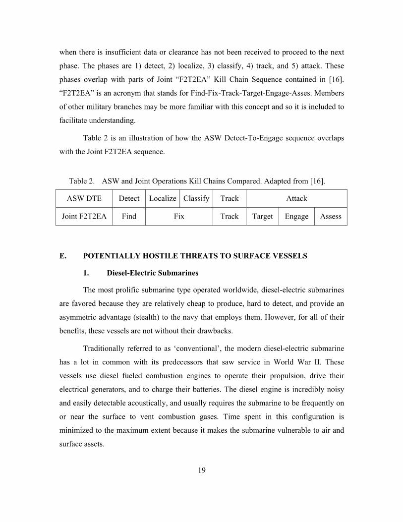
Table 2 is an illustration of how the ASW Detect-To-Engage sequence overlaps
with the Joint F2T2EA sequence.
Table 2. ASW and Joint Operations Kill Chains Compared. Adapted from [16].
ASW DTE Detect Localize Classify Track Attack
Joint F2T2EA Find Fix Track Target Engage Assess
E. POTENTIALLY HOSTILE THREATS TO SURFACE VESSELS
1. Diesel-Electric Submarines
The most prolific submarine type operated worldwide, diesel-electric submarines
are favored because they are relatively cheap to produce, hard to detect, and provide an
asymmetric advantage (stealth) to the navy that employs them. However, for all of their
benefits, these vessels are not without their drawbacks.
Traditionally referred to as ‘conventional’, the modern diesel-electric submarine
has a lot in common with its predecessors that saw service in World War II. These
vessels use diesel fueled combustion engines to operate their propulsion, drive their
electrical generators, and to charge their batteries. The diesel engine is incredibly noisy
and easily detectable acoustically, and usually requires the submarine to be frequently on
or near the surface to vent combustion gases. Time spent in this configuration is
minimized to the maximum extent because it makes the submarine vulnerable to air and
surface assets.

20
The story is vastly different when considering this family of submarines when
operating on battery. Like an electric car, a submarine operating on battery is very quiet,
and may provide only the faintest clues to its presence, namely cavitation and fluid noise.
These vessels generally lack the endurance found in the larger nuclear powered
submarines; however, because of this, the crews of diesel-electric boats tend to be very
familiar with operations in their local environment. This knowledge and proficiency
coupled with their stealth make them dangerous.
2. Nuclear Powered Submarines
Much more expensive to produce because of the manufacturing and scientific
costs associated with production, these types of ships only see service in the major navies
of the world like the U.S., U.K., France, China, and Russia. Using fission reactors as a
power source for propulsion, these vessels are much more expensive than diesel
submarines to produce but are not limited by a need for frequent surfacing. They can stay
submerged nearly indefinitely, constrained only by food reserves and crew endurance,
making them a formidable threat.
These vessels are very quiet, certainly far more than conventional subs on diesel
power, though they do have a critical vulnerability. The reactor aboard these vessels
requires a constant flow of cooling water to keep the temperatures in the reactor from
becoming critical. Flowing water requires pumps, and pumps make noise. To a keen ear,
or electronic sensor, these pumps could be detectable
While conventional submarines generally lack the sustained speed required to trail
or lead a target, the nuclear powered vessel has the speed needed to get ahead of many
surface ships. This is a major consideration, as it allows the nuclear submarine
commander to dictate the terms of an engagement, and frees them from having to rely on
ambush tactics. Additionally, because of their comparative size, nuclear submarines also
frequently carry nuclear ballistic missiles, sub-launched cruise missiles, and special
equipment for irregular warfare purposes.
21
3. Submarine Weapons
This section discusses the means with which a submarine has to ensure that it is
allowed a “vote” in an engagement scenario.
a. The Crew
It may seem a bit cliché, but a submarine is more than just a delivery platform for
a suite of weapons and intelligence gathering tools. Each submarine is operated by a
human crew and the vessel is an expensive instrument of national power. Therefore, not
only are you fighting the weapons, but the collective intelligence of the crew who is
driven by the same or similar motivations as our own sailors. The enemy is crafty, wants
to be elusive, and likely fears defeat and death as much as any other person. The inherent
strengths and weakness of the human mind are factors to consider when developing a
system that is designed to defeat them.
b. Torpedoes
The torpedo is the submarine’s primary close-in weapon and arguably its most
damaging. Unlike missiles, torpedoes have significantly shorter ranges, but they carry
much greater explosive payloads. There are many different types of torpedoes, to include
wake-homing and sonar guided, but functionally they all have the same aim: get under
the mid-point of a ship’s keel and explode causing a massive air bubble to form under the
ship that lifts it out of the water and breaks the keel. This cracking of the hull is
devastating and will usually cause the ship to split in two parts. A USV designer should
ensure that the vessel is able to detect a torpedo launch—a relatively simple task due to
the distinct and easily discernible acoustic signature. Once detected a few options are
available. First, the USV should immediately alert its controller, and all nearby assets of a
torpedo launch. Second, if equipped, the USV should attempt to lure the torpedo away
from its target by acting as a large counter measure. Third, and this may be more
difficult, but the USV system as a whole might be able to plot the torpedo’s track line and
get a reciprocal bearing. While the torpedo will certainly create a wake that is highly
visible during the day to an alert spotter, it would be nice to have more than a pair of
eyes.

22
c. Missiles
Submarines are capable of carrying an assortment of different missiles. For local
defense while a submarine is on the surface, many navies will arm their subs with what
are known as MANPADS, Man-Portable Air Defense Systems, more commonly referred
to by the more popular brand name “Stinger.” These shoulder fired weapons are intended
to engage low-slow-flying aircraft, particularly helicopters that should get within their
limited acquisition range. Moving up the lethality curve are the submarine launched anti-
ship or land-attack cruise missiles. These weapons usually require external queuing
sources or preset coordinates to be most effective. Finally, topping the scales on lethality
are the ballistic missiles, which reach sub-orbital altitudes before their warheads are
navigated to their targets. Ballistic missiles may carry conventional or nuclear warheads.
Air assets are most at risk to MANPADS, surface ships are most at risk to the cruise
missiles, and Carriers are at risk to ballistic missiles.
There is not much a USV outfitted for ASW can do about an incoming missile,
but consideration should be given to determine how one might quickly increase the radar
cross section or IR signature of the USV in an attempt to be a counter to an incoming
missile.
d. Mines
Other than directly attacking surface vessels, submarines are well adapted at
laying down a mine field covertly. Nautical mines, like their land cousins, are nefarious
weapons that often do not discriminate between their targets. Ocean mines can have
multiple types of triggers. The most common are contact and induction triggers. Contact
mines as the name suggests will not detonate until something physically contacts one of
their fuses. Induction mines will either wait for a magnetic field to pass by releasing a
mine to float to the surface and then detonate via contact or the magnetic field will be
enough to set off the explosive. Mines aim to achieve a hard kill in a similar fashion as a
torpedo, by exploding underneath a vessel thereby cracking its hull. Alternatively, a mine
can be just as deadly when it punctures a hole in the side of a ship and causes
compounding emergencies. For a modern example, see the USS Samuel B. Roberts case

23
study in [17]. The “Sammy B” struck an Iranian mine that broke the keel and caused
severe flooding and fires. It was only through the hard work of the crew that the ship
survived.
Mines serve a strategic purpose by acting as a hazard to all maritime traffic.
Mines are a convenient and economical way for an adversary to shape the battle space
and political discourse to their advantage by creating choke points and barriers where
none existed before. These obstacles can produce a funneling to maritime traffic that a
submarine could use to its advantage.
Mine hunting has similarities with sub hunting, and it has been proposed in [2] that
USVs could also be used as mine-hunters. More study would be required to determine if an
ASW USV could serve double duty as a mine-countermeasure (MCM) USV.
e. Counter Measures (CM)
As if hunting submarines was not difficult already, the cat and mouse game that
exists between the technology to hunt submarines and the sub’s ability to defeat or at
least distract said technology is well known. In the zero-sum game of ASW, counter
measures serve to give the submarine a few more moves before it is faced with a loss or
can ensure a win. Counter measures include everything from low-tech static noise
makers, to high-tech decoy UUVs.
The purpose of a counter measure is to deny the adversary the ability to gain a
firing solution. If that action has failed and the enemy has fired a weapon, then CMs are
used to try to defeat the weapon. The counter measure game becomes one of escalation
where one side will develop a weapon to destroy their opponent, which drives the
opposing side to develop a CM to defeat the weapon or targeting system. Then, as is
natural, the initial side will then build into its software or hardware an ability to detect
CMs thereby defeating them, and so on and so forth.
Understanding that subs may use CMs is important because it is likely that a USV
will encounter them during the course of its service life. For example, a submarine,
having been detected by the USV, might launch a CM to distract a USV before the USV

24
can gain a better track or fix on the submarine. Think of it as similar to a magician’s
sleight of hand. The USV needs to know or learn the particular characteristics of CMs in
order to ignore the misdirection so as to focus on the submarine’s true signature.

25
III. AUTONOMOUS SYSTEMS FOR ASW
Before one can begin to design an autonomous system, one needs to know a
couple of key pieces of information. This document will not attempt to push any
particular definition of autonomy but it is import for the reader to note that this is a
contentious issue in the robotics field because the term ‘autonomous’ carries with it much
weight from other fields of study like psychology, sociology, and philosophy. These
groups have been trying to characterize autonomy in humans with varying definitions.
This is a sticking point for the robotics community, as it is a relative newcomer to the
discussion. Artificial intelligence comes to the proverbial table missing a key component
—morality/soul/feelings, an aspect which is critical in the study of autonomy in humans,
in a thought: “free will.”
Additionally, a distinction needs to be made between “autonomous” and
“automatic.” The terms “autonomous” or “autonomy” refer to the agent’s ability to
perform tasks with limited human involvement, whereas “automatic” or “automated”
simply refer to behavior that is scripted and predictable given a certain start state.
Algorithms are used to automate a system when much of the problem space can be
covered by the algorithm. However, things become tricky when you begin dealing with
many unknown and unpredictable behaviors.
The following sections lay out some concepts that are important to understanding
autonomous systems in general and an ASW USV in particular.
A. THE AGENT
The term agent is derived from the Latin word “agere” or “to do” [18]. Simply
stated, an agent is an entity that performs actions. Certainly, this word may have an
overly broad definition, though it is useful to use in place of pronouns. For the purposes
of this paper, agent will refer to the high-level construct of the USV as a whole,
understanding that this high level entity may actually be composed of sub-constructs of
other agents, each with their own distinct behavior. The following sections discuss
different aspects of an autonomous agent.

26
1. Artificial Intelligence
To begin to understand the limitations imposed on an autonomous system, it is
important to remember that despite how “intelligent” it acts, it is still just software. At the
risk of insulting our future robot overlords, this comment is not disparaging, but a
statement of fact. When someone says that they have created artificial intelligence, they
are saying that they created software or hardware that mimics the interactions that
humans have, and in some ways is convincing enough that an outside observer might
think for a moment that they are interacting with another human. This thought is the basis
for the Turing Test. Alternatively it could mean that the software came up with the same
or better solution than a human did given the same stimulus, as in a game of chess.
Alan Turing, of Enigma fame, is a legend in computer science. In 1950, Turing
proposed a challenge: a computer with artificial intelligence as an attribute would appear
to display human level intelligence under the certain conditions. The passing conditions
were: after being given a set of written questions, the computer then independently
composes written responses that an observer is unable to distinguish between human and
computer. This test implies the need for optical scanning, natural language processing,
and an extensive knowledge base from which to craft an answer [3]. This challenge was
initially known as the Imitation Game and is now known as The Turing Test. The passing
conditions for this test have been further refined and the test can be thought of as the high
bar for any potential AI to meet. However, it is a bit limited in its scope and not all AI
agents need to meet this standard.
2. Rationality
An action is said to be rational when it is performed to accomplish the best
possible known outcome, emphasis on the word known. If there is uncertainty, or there is
not enough time to make a well thought out decision, then an actor selects an action to
support the best expected/projected outcome given the time and resources to do so. The
later notion is referred to as limited rationality in [3]. The smart designer wants his or her
system to be rational, following logic and rules, rather than choosing randomly, or
knowingly choosing an incorrect move. It is important to stress that there may be an

27
occasion that a rational actor needs to select an action at random, but this must be on
purpose with the ultimate goal of achieving its objective. For example, a robot finds itself
at a fork in a road, and knowing nothing of the paths that lay before it must select to go
either left or right. If the robot is not allowed to back track, and must select either choice,
then it may do so “randomly” and still be considered rational.
To help illustrate the point, Russell and Norvig suggest that rationality at any
given point relies on four things, from [3]:
The performance measure that defines the criterion of success.
The agent’s prior knowledge of the environment.
The actions that the agent can perform.
The agent’s percept sequence to date.
3. Sensors and Actuators
As mentioned in [3], sensors are used by an agent to perceive its environment. In
the case of the ASW USV, sensors would include sonar, radar, cameras, GPS, and others
as deemed appropriate. Actuators are anything that the agent uses to act upon its
environment [3]. For this craft, its actuators will be its propulsion system, stability and
helm (steering) control systems, communication systems, and if the USV were armed, the
weapons systems could be considered actuators.
4. Perceptive Sequence
Russell and Norvig define a percept in [3] as referring to the agent’s perceptual
inputs at any given point in time. Therefore, according to them, a percept sequence is the
entire history of everything the agent has perceived up to that point in time.
5. Agent Functions
An agent function is described in [3] as the mathematical mapping of any given
percept sequence to an action. A table could be constructed to host every percept
sequence (Ps) from Time = 0, till Time = n, but that table would grow very large, very

28
quickly, growing without bound. In reality, one is only concerned with smaller slices of
time in which interesting changes to the environment have occurred.
6. Agent Programs
The agent program is a counterpart to the agent function. As stated in [3], the
agent function is an external observation of what the agent has done, while the agent
program is what is actually controlling actions at each instant in time. The agent program
is the internal programming that is responding to stimulus and performing an action.
Once the action has been completed, the precept sequence that resulted in that action
could be logged in the agent function.
B. THE ENVIRONMENT
The term environment needs some disambiguation. First, for the purposes of this
document, consider the term ‘task-environment’ to refer to the problem space that the
USV is a solution too. This task-environment also includes the physical and or virtual
environment, but those will be discussed separately. Russell and Norvig recommend the
following acronym, PEAS, for defining the Task Environment. The following list is
adapted from [3].
P – Performance Measures – quantitative metrics need to be defined for the agent to determine how successful it is in a given environment. In the case of USV, measures might include: Minimum travel time between waypoints, minimum fuel usage, minimum COLREGs violations, and minimum false positives.
E – Environment – this is the physical (or virtual) environment that the agent is operating in. For the ASW USV, this environment would include other surface and subsurface vessels, hazards to nautical navigation, underwater topography, maritime traffic separation schemes, and sea state – to name a few.
A – Actuators – as previously mentioned, these are parts of the vehicle that interact with the outside world. Examples: Rudder controls, engine throttle, trim servos, navigation lights, external interface panel/touch screen, etc.

29
S – Sensors – as mentioned, these are the instruments and sensors the vehicles uses to perceive the environment. Examples: Fathometer, GPS, compass, radar, electro-optical devices (infrared, true color), sonar, etc.
C. THE PROBLEM
The previous sections discussed the submarine threat, its capabilities, the
underwater environment, artificial intelligence, and autonomous systems. This serves as
the framework for the real design challenge.
1. Protecting the Battle Group
The United States Navy has identified the following area as being suitable for
employment of USVs: peacetime ASW in performing the Maritime Shield and Protected
Passage missions from [1, 2]. These missions serve to push out the battle groups sensor
net to expand the area at which a high value unit (HVU) like an aircraft carrier may
operate free from harassment by submarines. This problem does not concern itself with
attempting to detect all submarines in the ocean, or trying to follow submarines from
their homeports. Battle group protection is about forming a perimeter around the HVU
that, with reasonable probability, is clear of undetected submarines. The crew of an
undetected submarine has a significant advantage over their opponent—surprise. Once
the submarine’s crew knows they have been detected, their advantage of surprise is
diminished, and hopefully they feel that the risk of a successful counter attack would be
too great as to be too risky their safety.
2. Two Scenarios
As mentioned, two scenarios are being considered: maritime shield and protected
passage. Both of these scenarios are centered on the HVU, but one is stationary (Shield)
and the other is mobile (Passage). The two mission areas are shown in relation to each
other in Figure 2.

30
Figure 2. ASW Nomenclature. Source: [1].
Maritime Shield is focused on protecting the MODLOC or CV (Carrier)
Operations Area (CVOA), that body of water that directly surrounds a HVU where the
HVU will be operating for an extended period of time. Traditionally this body of water is
laid out as a square with the HVU at the origin, though it could also be a circular shape
out to some radius from the HVU. No matter the geometry, the shape remains stationary
even though the HVU may be moving inside. The HVU is vulnerable because after a few
days of observation, an adversary may be able to suppose where the HVU is or will be
and take steps to neutralize it. Having early warning of a perimeter breach is important to
prevent this situation. This mission is illustrated in Figure 3.

31
Figure 3. Example of Maritime Shield. Source: [1].
Periodically, it is necessary for the HVU to reposition itself, sometimes hundreds
of miles away to another MODLOC/CVOA. In this situation, the HVU becomes
vulnerable to an ambush or a flanking maneuver. When the HVU is in transit, it becomes
susceptible to attack from a submarine that may be lying in its path, like a coiled viper, to
strike as the unit passes overhead. Similarly, the HVU could possibly be funneled into a
kill box composed of a well-placed mine-field or potentially hostile SAG. Furthermore,
the HVU is concerned with the reach of land based area denial weapons, of which the
adversary is well acquainted with the ranges and therefore limitations, and could attempt
to push the battlegroup into this range. If the HVU avoids possible ensnarement and
traps, it may still be vulnerable to attack while its figurative back is turned. The baffles
are a well-known region behind a ship where its acoustic sensors may not function very
well. A submarine can exploit this region to sneak up behind a ship and fire a weapon to
follow the ship’s wake. Delousing, as it is called, is the part of the mission in the
vanguard where units are actively trying to “push” submarines out of the intended travel
path. No special term exists for covering the rear, but it is just as important that someone
does not sneak in from the sides or rear flanks of the formation. This mission is illustrated
in Figure 4.

32
Figure 4. Example of Protected Passage. Source: [1].
3. A Note on Complexity
In the information sense-making process, there is a model known as the Cynefin
framework that helps form a discussion on systems. In developing the software
architecture for a USV for ASW, it is important to understand what kind of problem
environment one is dealing with to ensure that developed solutions are likely to fit. In this
model from [19], five domains exist (in order of increasing complexity): simple,
complicated, complex, chaotic, and disorder. Simple systems are those that have a strong
cause and effect relationship and information is ordered. Complicated systems have a
recognizable cause and effect relationship, but may require some analysis to discover it.
There may be multiple “correct” ways of solving a problem, but it hinges on an expert’s
experience to select one that makes sense. In a complex environment, cause and effect are
obvious post hoc with only light constraints on agents. A chaotic environment has very
little order and any decision is probably as good a decision as any other [19]. Finally,
disorder has no useful structure. D. Snowden, the author of the Cynefin framework, states
that disorder is the natural state that most people and environments are in until they have
been better understood and can start working from one of the other domains.
While it would be nice to claim that non-wartime ASW could be considered
simple that would be a flight of fancy. This author’s assessment is that this phase of ASW
33
falls somewhere in the complex or complicated regions of the model. For a moment,
suppose one eliminates some of the variables about acoustics in the open ocean and
assumes a constant speed and therefore highly predictable nature for sound propagation.
This assumption would alleviate much complexity, but one would still be left with the
human component. One could attempt to make assumptions on human behavior, but
those assumptions should be characterized as foolish at best and deadly at worst. For
example, one might assume that all submarines from allied countries are friendly and all
submarines from non-allies are potentially hostile, and this is probably an assumption that
most commanders make…but it is flawed, as friends can quickly become enemies and
enemies may not always attack.
Suppose one were to assume that a submarine belonging to a country called
Orange is detected close to a high value unit of a country called Blue, then that submarine
is considered potentially hostile by Blue. This is a fair assumption from the defensive
standpoint of Blue, it does not hurt to think that a submarine belonging to a potential foe
(Orange) might attack without provocation; after all, one is only a bullet or torpedo away
from a war…. Therefore, Blue takes appropriate defensive measures in accordance with
ROE and doctrine. For the Trekkies (Star Trek fans), this would be the equivalent of
setting “Yellow Alert.” Now suppose that it is observed that Orange’s submarine has
come to periscope depth, radiated radar, and has been acoustically detected opening
torpedo or missile tubes. Blue is now faced with a hard choice, does he attack Orange
preemptively before Orange has shot a weapon, or does he wait…knowing that only the
utterance of the word “Fire” stands between a warhead and Blue having to defend
himself? Both actions have risks and consequences. The answer is…it depends, and that
is why a ship’s captain is paid the proverbial big-bucks to decide. This scenario is given
to hint at the inherent complexity of just the human element, let alone the physical
environment. When taken in summation, ASW in non-wartime can best be classified as a
complex domain.
You might be wondering, “Why is this important?” The proposed USV system
must operate in this environment, and it is vitally important to engineers, programmers,
operators, and policy-makers to understand the inherent limitations imposed by such a

34
dynamic situation. It will be impossible to make a USV that operates perfectly in all
situations, as it is practically impossible to predict every possible action and reaction that
every agent will make, especially agents that may not always be acting rationally.
Instead, the user of this system must be satisfied with a system that is limited in scope,
ability, and applicability, and therefore must craft the test and verification cases carefully
to ensure proper operation for the most critical of functions.
In other words, rely on a USV to provide information that informs the decisions
and actions of humans. The challenge is to anticipate what information skilled users will
need to make good decisions.
35
IV. DESIGNING A SOLUTION
On the surface, maritime shield and protected passage may appear to be
completely different problems, sharing only a common operational area. However, the
more one considers it, the more it becomes obvious that from a software perspective, the
scenarios are close enough to each other that a common solution can be developed.
However, there is a strong caveat—while the software may be identical, the hardware
probably will not be. Both mission sets share many traits; however, Protected passage
favors a vessel that trades endurance for speed based on a need to stay with or ahead of
an advancing HVU. The maritime shield mission, being one where the HVU lingers in an
area for a considerable amount of time lends itself to a design that conserves energy and
requires minimal interaction with support vessels.
A note on employment: it should be considered that a blended/hybrid use of both
of these types of platforms will likely yield the most defensive advantage to the HVU. A
protected passage hull form would have speed enough to traverse the near-mid range
areas around an HVU to quickly prosecute any strange readings that a Maritime Shield
hull form detects. Instead of trying to engineer a solution that fits all scenarios (poorly), it
would be wiser to design two dedicated platforms that execute their respective missions
exceptionally well, and then use them in concert with each other to minimize their
disadvantages while capitalizing on their advantages. To be succinct: keep it simple, have
defined roles, avoid multi-mission, and realize that mission creep is inevitable.
This chapter is organized in the following manner: Sections A through C are the
preliminary sections that set the framework for a discussion. Sections D and E outline the
design while Sections F through I discuss each major module.
A. REQUIREMENTS ANALYSIS
The purpose of requirements analysis is to determine a customer’s needs in sufficient detail to plan the construction of a software system meeting those needs. [6]

36
In this section, the requirements of an ASW USV are detailed. Few of the
requirements have been stated explicitly, many have been stated implicitly. A larger
number still have been derived when taking the implied and explicit requirements to their
logical conclusions.
Problem statement: The purpose of the shipboard ASW USV control system is to
enable a single operator or a team of operators to manage one-to-many USVs in support
of ASW operations in the vicinity of a HVU and its escorts.
This is a plain language statement from the perspective of the customer [6], in this
case the U.S. Navy, which will guide the rest of the development process. The vagueness
of the statement is a result of the vantage point it was made from, we will call it the
thirty-thousand foot view. At that altitude, everything is tiny and imprecise, but it will be
necessary to break this statement open to further define requirements and to build a
model that integrates all the requirements.
B. ASSUMPTIONS
The following is a list of the initial planning assumptions on how the USV system
should operate:
The USV will not be used as a weapons delivery platform.
The USV will not be regularly operated in known combat areas. Self-preservation, passive defense measures only
The USV will likely be used in partially, but not fully degraded communications environments.
Near-Real Time C2 is sufficient; some latency in the receipt and execution of commands to USV is permissible.
The USV is not intended to be a replacement for any current system, but rather an augmentation to existing platforms.
The USV control system will be able to be installed aboard LCS or larger warships.

37
C. SETTING THE AUTOMATION BOUNDARY
For the scope of this project, the solution space is defined as starting from an
individual USV, proceeding to a central command module, and terminating with an end
user. Integration with other existing systems will be discussed as necessary, but further
study into integration will be required before adoption of this system. Setting the
automation boundary functions similar to stating the scope of a research study; it
identifies what is and is not inside the responsibility of the automated system, as
illustrated by Figure 5.
USV Module – Hardware/Software Layer
C2 Module – Domain Layer
HCI Module – Presentation Layer
Control Module
Unmanned Systems Mission Manager
SpecialistSpecialist
Specialist
ObserverObserver
Observer
Figure 5. Automation Boundary

38
D. DESIGN AND ARCHITECTURE
This system is composed of three distinct software components that together form
one system. These components are the USV module, command and control (C2) module,
and the human computer interface (HCI) module. In the following paragraphs, the
thought behind each module is explained as well as the considerations for each module.
The design for this system is influenced by the desire for simplicity and
modularity. The goal being to avoid a monolithic structure that becomes difficult to
modify and manage. Additionally, the design follows a classic three-tier approach as
suggested by [20], where the USV encompasses the hardware/software layer, the C2
module encapsulates the domain layer, and the HCI module encompasses the presentation
layer. Each layer is functionally separate except for the needed cross layer connections.
This approach supports the modularity aspect, and allows changes made to aspects of one
module to have minimal to no impact on other modules. The main goal here is that if one
wants to repair, replace, or add functionality to the HCI module, it should not “break”
anything in the C2 or USV modules and vice-versa.
The hardware/software layer is concerned primarily with controlling the hardware
that is aboard each USV, and with converting raw sensor outputs data into digital data
that can be more easily shared and manipulated. The domain layer as discussed in [20] is
concerned primarily with managing the business rules of ASW, remote vessel operation,
and acting as a clearing house of information to be used by the presentation layer.
Finally, the presentation layer is concerned with displaying information to the end-user
and capturing the user’s input to control operations. In a tiered architecture, the lowest
layer has very little awareness of the higher layers, it simply does what it needs to do and
keeps operating until it is stopped. As one ascends layers, their awareness grows but their
influence on lower layers diminishes.
The following list has a brief overview of each module before the more detailed descriptions that follow
USV Module – Primarily a data gathering and limited information-production agent. This module performs many “housekeeping” functions associated with an autonomous vehicle. Its primary objectives are to go

39
where instructed, not run into things along the way, operate onboard sensors, and if necessary-follow assigned targets.
C2 Module – Data and information fusion agent, keeps track of USVs so that humans do not have to too. Produces info to be consumed by HCI module or other consumers as required.
HCI Module – Information presentation and human input gatherer. Produces no new information.
E. AREAS FOR AUTOMATION
The purpose of this section is to discuss areas that can benefit from automation or
refinement to present automation if already automated.
1. Detection
Detection is arguably the most important part of ASW; it is the point from which
all other actions are measured. If one does not detect anything, then they need to keep
searching until they find something or they are directed to cease searching. To return to
the discussion on complexity, ASW before detection could be classified as disorder or
chaos, the equivalent of watching the static on a television looking for an image to show,
even if just briefly. Granted, one usually does not perform ASW unless there is a reason
to suspect that there might be submarine activity, after all there are other threats that
could impact the mission far before a submarine does. The battle group commander has
limited human and vehicle resources and so he must be wise with the expenditure of
effort. However, even when a commander has established an ASW watch team, there is
no guarantee that an adversary will show up. When this occurs, it leaves the watch-
standers fixed at their stations hoping to see something interesting.
This is a waste of human resources, to dully sit and watch a screen until
something interesting appears or until the ASW team gets better queuing information.
This then becomes a candidate for automation, but one must be cautious—unless a search
algorithm is properly configured, the operator may be inundated with false positive alerts.
This is where an artificial neural network (ANN) may show its true potential. By using
the ANN with a search algorithm, a search program could comb through data sets
collected from the USVs in near real-time through offline processing. While the

40
information would be time-late, it would help to establish a high probability that a contact
of interest (COI) exists in the search region. It may even be possible to establish an initial
position, known as a datum. This is helpful because an area of uncertainly can be plotted
from that point. By using heuristics and simple reasoning, operators may then be able to
place sensors in the water that will yield more information.
Detection requires a low false positive rate because the sensors that would be used
to investigate a possible contact are expensive to use with respect to time, and unit cost.
2. Localization and Tracking
Localization, also called fixing, is the process by which an initial position
estimate of the target is obtained and follows after detection and dovetails into tracking.
Localization is the step in ASW after initial detection where the team attempts to
establish a Datum or a follow on fix from a Datum. Once course and speed have been
established for a contact the team moves on to tracking i.e., the process by which a fix is
updated as the target moves.
a. Considerations
While signal processing is quite robust aboard current ASW assets, it is still
policy to require a human to evaluate the presented information to create an initial line of
bearing to an underwater contact. After obtaining multiple lines of bearing, a positional
fix can be established for initial target tracking. At this point it is possible for an operator
to hand over tracking to the computer, and they often do. However, the wise operator will
also continue to maintain their own track of a target for backup.
Current tracking algorithms generally function well; however, they do not
perform well with minimal information or time-late information. As a result, the area of
uncertainty around automated tracks may grow quickly when “fresh” contact information
is unavailable. Many tracking algorithms use a form of least-squares regression to plot
track-lines. These track-lines can become skewed when junk information is supplied. The
phrase “garbage in, garbage out” is common when discussing such algorithms. A human
operator is not as easily fooled by tactics that a submarine may employ to throw off a

41
hunter and is usually more selective about which data points are incorporated into their
tracking solution.
Improvements to the automated tracking algorithms would greatly improve the
accuracy and reliability of the generated tracks. It would be helpful if the system
recommended a location for the next buoy drop, or where to position a USV.
b. Implementation
Tracking the submarine should be performed by the C2 module, as it will have the
best SA of the mission and all the other moving parts. However, the vehicles need to be
adept at knowing where other USV’s in the group are so that each can benefit by
collective track processing for the same contact.
This task is more complicated than simply updating the fixes from acoustic
sources to come up with an accurate track of a contact. This task would ordinarily require
the placement of more sonobuoys in the predicted path of the submarine, but if the USVs
could sprint ahead just a few hundred yards, then they themselves would be able to form
a tracking chain. To accomplish this will require a few key enablers: each USV group
needs to know where its neighbors are for collision avoidance purposes, and to ensure
placement in a logical spot. The USVs may not know which vehicle has the best contact
with the submarine, so it is therefore contingent upon the C2 module to track this
information and ensure that only those vehicles that are down Doppler with increasing
integration times are repositioned. Additionally, this will require the USVs to be able to
communicate with neighbors to share acoustic data relevant to tracking.
3. Dynamic Event Notification
In the ASW lexicon, a dynamic event is an acoustic event of significance with the
following examples: speed change, course change, depth change, or CPA on a sensor.
These events may register as a shift in sonic frequencies observed (Doppler shift), a
sudden increase or decrease in volume of a sound source, or even a complete loss of a
signal. These events are of such importance that the operator needs to be alerted
immediately when one occurs. Initially, a dynamic event will be observed on the USV,
42
which will send a notification to the C2 module which will then generate the message for
display through the HCI module.
4. Contact Classification
Assigning a classification to an underwater contact is a labor intensive process.
The process begins at initial contact, where an operator attempts to make an early
decision if the new acoustic contact is biologic or not biologic. This is important because
it is a waste of time to track whales, dolphins, and schools of fish. Next, a human
operator needs to decide if the contact is something on the surface, something in the air
passing overhead, a fixed shore based facility, etc. Next, once it has been decided or
determined that the contact is likely to be a submarine, it is then necessary to determine
who it belongs to. As a matter of practice, the U.S. Navy prefers to minimize the amount
of time spent tracking their own submarines, as presumably the submarines know where
they are. There are multiple channels to do this, but usually a quick chat with the
Submarine Operating Authority (SUBOPATH) will eliminate the possibility of
expending wasted effort. SUBOPATH is responsible for knowing where friendly
submarines are operating. Once a submarine is determined not to be an ally, the process
of attribution begins. While this may still seem like a long list, and it is, there are only a
few major variants of submarines that have been exported or developed elsewhere. The
arduous task now becomes matching the signals observed to known or predicted
signatures.
This task is ripe for automation, but it requires the C2 module to have access to
ACINT databases, SIGINT databases, and as many rich and varied data sources as is
possible. Additionally, it requires quite a bit of experience and expertise in making
accurate attribution decisions.
5. Signal Processing
Currently, signal processing is already heavily automated, with the acoustic
processors on-board the MH-60R “Romeo” Seahawk and P-8A Poseidon performing
much of the heavy lift. Using beamforming techniques, along with different filters and
amplifiers, signal processors clean up a lot of the noise in the underwater environment

43
before it gets to the human operator. The human operator then fuses the information
displayed with their knowledge of submarine TTPs and knowledge of what separates a
sub from surface vessel or a whale. A sensor operator is looking for Doppler shifts in
frequencies as well as bearing shifts to indicate some sort of dynamic event. These two
particular events would usually correspond to a contact reaching its closet-point-of-
approach (CPA), or changing direction.
6. Navigation
When discussing navigation, it is important to be explicit because there is a
decided difference between finding the shortest route between two points and
successfully moving though the real world to get there. When most people think
“navigation” they think the latter, but programmers can often mean the former. The
procedure to find the shortest route between two points is not a trivial problem for
computers to perform. In fact, some of these problems fall into the category of NP-Hard
and NP-Complete problems. A well-known computationally challenging example is the
traveling salesmen problem (TSP). The TSP is an optimization problem where one is
given a list of cities and the distances between each pair, with the request to find the
“cheapest” route [21]. Cheap may be in respect to time, distance, or some other
optimization factor. This is a seemingly simple problem, but can become quite
computationally intensive. To avoid the computational complexity issue, heuristics have
been developed and there are known solutions to specific instances of a TSP. A USV is
likely to face routing problems, especially in constrained waters like inland waterways
and navigation channels.
Autonomous navigation is a tough problem because it requires quite a bit of
information to be seamlessly fused, the least of which is the geographic path, and
appropriate decisions made. In addition to the route planning problem, navigation is not
considered successful until an agent reaches their objective. This requires the agent to
maneuver around any obstacles that might be in their way. There are many tools with
which to detect objects, and the selection of those tools will depend on the tolerance for
errors. Radar and sonar are great tools for getting gross estimates to targets, but there is

44
an inherent amount of imprecision in these sensors. This imprecision increases as one
considers dynamic motion for both the interrogator and the interrogated. Lasers are great
for obtaining very accurate distances, but their range is limited by line-of-sight as well as
atmospheric obscurants like dust and moisture. GPS is another great tool that can provide
high precision and accuracy, but it carries with it a significant vulnerability if it is the
only instrument used in navigation. Additionally, GPS allows the user to resolve their
position to a point with a small area of uncertainty of only a few yards/meters.
Once an agent has accurately resolved their current position on the globe, and
identified obstacles to avoid, the task of navigation is almost complete. Humans have
developed complicated sets of rules to govern the safe and orderly conduct of maritime
traffic, which are encoded in the following example publications: International Maritime
Organization’s (IMO) Convention on the International Regulations for Preventing
Collisions at Sea (COLREGs), the U.S. Coast Guard’s Navigation Rules and Regulations
Handbook, which is commonly referred to as “the (maritime) rules of the road” that
govern traffic inside U.S. territorial waters [22], and UNCLOS. This is not an exhaustive
list but serves as a functional example. In order to increase the autonomy of a USV it is
necessary that the vessel complies with the rule sets, understands when there are
conflicting rules and can resolve contradictions and situations where other vessels are not
following the rules.
DARPA advertises the ACTUV/Sea Hunter as being able to comply with all these
regulations, but aside from this example, most other commercial and military programs
still lag behind in this area. In order to accomplish this feat, advanced artificial
intelligence is required to be able to internalize the human rules, and make appropriate
judgments to dictate movement decisions. This research area is still open for
development and advancement.
7. Formation Movement and Station Keeping
Formations of vehicles provide advantages over loosely coupled or
unsynchronized single unit operations. A formation, by its nature implies that vehicles are
in closer proximity to each other than is considered normal or safe. The burden to define

45
what constitutes “normal” and “safe” is left to specific domains. Speaking in general, as
the proximity between craft decreases, the probability of a collision increases. A collision
at sea or in the air is considered a severe consequence due to the potential for loss of life
or costly damage to equipment. Therefore, formation operations are considered to be
higher risk evolutions than non-formation ops.
The increase in risk from operating in formation is mitigated through close
coordination and standardization of movements. Additionally, the risk is outweighed by
the benefits of operating in formation. This assessment is task dependent and is not
appropriate in all operating conditions. The benefits from operating in formation include:
easier control of many units through clustering/abstraction, division of labor and
responsibilities to other formation members (like navigation or communication), as well
as mutual support and overlap of sensor coverage. The sub-task of maintaining a relative
position with respect to a guide is known as station keeping. Station keeping is a
concentration intensive task for humans due to the need to constantly adjust a vehicle’s
movement in order to remain in a designated position. The intensity of this task is
relieved by increasing the separation between individuals.
By acknowledging the risks and the challenges of formation operations,
employment options are increased. Operating USVs in formations allows for a single
human to control more units than if they were to try to control them as individuals. This
abstraction is what will allow the savings in manpower that is sought.
F. THE USV MODULE
An overarching design philosophy for the USV software is the Keep-It-Simple-
Stupid (KISS) principle. When software gets bloated, it becomes hard to maintain. The
developer should ensure that the software that runs aboard the physical platform is kept to
the essentials. The definition of “essential” is task specific, though for this problem the
following are considered essential: propulsion and steering control, navigation and
obstacle avoidance, communication link to control entity, and of course, sensor
interfaces.

46
The advantages of adhering to this mentality are that it makes the job of
maintaining a code base easier, and it simplifies the process of adding future
functionality. A. Oliveira in his dissertation [5], titled conspicuously “Software
Architecture for Autonomous Vehicles,” runs with this idea of simplicity. In the report,
he provides a clean technical outline of the software for an unmanned surface vehicle for
use in commercial ventures. Many of his ideas influence this work, as there were some
critical insights that were beneficial to this project.
Two reports of interest, [23] and [24], detail the efforts of multiple computer
science students to formulate software requirements for a USV. In [23], a group of
students taking a software methodology course offered by Dr. Berzins at the Naval
Postgraduate School (NPS) approached three different ASW employment contexts:
littoral operations, carrier strike group operations in deep water, and theater-wide ASW.
The findings of the six groups that participated were condensed into a single set of
requirements that represented a general set or requirements for an ASW USV. The
following year, a second study as described in [24] tackled the same design challenge
with a tighter scope. Two teams each, for four teams in total, worked on the maritime
shield and protected passage sub-mission sets of carrier strike group operations in deep
water. The requirements generated by the student groups were again consolidated. The
designs were also briefed to experts in the field of ASW and the feedback of these experts
as captured in the report. Both of these studies were sponsored by OPNAV.
To avoid a duplication of effort, this thesis uses the feedback provided by the
subject matter experts to inform the design of the C2 and HCI modules. It should be
noted that none of the students that participated in the second study had any experience
with ASW. With only a brief introduction to ASW, and in the reading material that is
openly available online, the students were still able to design software architectures
without any bias towards what a solution might look like. While their designs were
insightful, given their lack of familiarity with the domain, there are some oversights. The
following sections seek to address those shortcomings.

47
1. Hardware Interfaces
First and foremost, [5] recommends keeping the software independent from the
hardware and that the choices in components should allow for all current and future
interfaces. This recommendation recognizes a key characteristic of software and
autonomous systems—change. It is important that future operators have the ability to
upgrade sensors, or to modify the code without breaking the entire system. To do this
sensibly, one needs to select or specify hardware that has standardized external interfaces
(ex: USB, IDE, RS232).
2. Operating System
Each USV, regardless of variant, will have an operating system (OS) loaded on it.
In the absence of guidance relating to operating systems, a LINUX based operating
system is recommended. In comparison to other operating systems, a Linux base allows
for more customization, which has many benefits. First, a developer can trim parts of the
OS out that are not needed for the operation of the USV. This adheres to the minimalist
principle recommended in [5] while presenting a smaller attack surface towards a
potential cyber-attack. An advantage to using the Linux OS is that it treats everything
from a DVD player, a file folder, or a desktop monitor as a file. For the uninitiated, this is
a benefit because sensors, actuators, as well as any number of devices can be addressed
as a file by the file system. This is in contrast to other operating systems that treat these
objects differently. Ideally, this ease of use will also allow for easier code maintenance.
Different hull variations will have different equipment, capabilities, and
limitations. Fundamentally, the software does not care about the differences in hardware,
so long as an OS is chosen that allows for easy device driver configuration, also known
as Plug-n-Play. On startup, the OS will poll all connected hardware, determine what is
installed, load the appropriate device driver from a library, and then set its internal state
to register the new limits. For instance, if the vessel is commanded to transit at 20 knots,
but the hardware is incapable of supporting that speed, then an exception will be thrown
and reported to the C2 module.

48
3. Outgoing Communications
To keep things simple, there are only three categories of data that should originate
from the USV. The first category is monitoring and control (MC), the second category is
sensor streams (S2), and the third is group coordination (GC). Limited communication
resources (time, bandwidth, frequencies) imply a need to keep the size and quantity of
data packets to a minimum. The divide between MC and S2 is intended to separate the
generally smaller sized but more numerous MC messages from the larger S2 streams.
Also, it will be necessary to be selective about which USVs provide S2 data. The first
two categories of data communication are transmitted by the USV back to the C2 module
while the third category, GC, is only communicated between USV members operating in
a group. These messages are used to de-conflict travel paths, share contact information,
and to maintain formation stations.
MC data will consist of all the administrative communications like
acknowledgement of packets, sending of status and position reports, and warning
notifications. Warning notifications are those messages that signal to the C2 module and
the HCI module that there has been some error aboard the USV that requires attention.
Some errors will only need to be logged; others can be taken care of between the C2
module and USV, with the remainder requiring human intervention. Obviously, the
messages that require human actions should be limited to only the most important, so as
not to inundate the operator.
Because of the nature of the S2 data, it is important to allocate a “thicker pipe” to
this source. However, at no time can the MC data be neglected, so it must always have a
dedicated link for each USV. A communications engineer will need to identify the most
appropriate communication protocol that allows many units to realize virtually
synchronous communications. However, lacking the expert guidance, the
recommendation is to use a protocol similar to TCP for MC messages, and RTMP for S2
streams. In the case of MC messages, it is important to know that the C2 module actually
received the message, and a TCP like protocol will provide this verification. In the case
that a message was not received, after some time-out period, the USV would resend the
message until it received an acknowledgment. For the S2 streams, this kind of

49
verification is unneeded but not unwarranted. Use of RTMP allows for similar kinds of
handshakes that occur with TCP, but it is optimized for pushing larger chunks of
information. RTMP allows for the transmission of live broadcasts as well as previously
recorded productions as specified in [25]. Streaming services like Livestream and
YouTube use RTMP for their live streaming data [26]. RTMP allows for recording of the
stream as well as each chunk of data has its own unique identifier that allows for a
reconstruction of data.
4. Incoming Communications
The only pieces of data that should be coming to the USVs are
instructions/commands from the C2 module. Instructions are sequences of commands
that are issued to the USV for execution. Some instructions are to control the sensors and
their settings, others will be for updating navigation waypoints, and still others will be
used to dictate actions in the case of an emergency. Just like the outgoing
communications, these messages will need to be decrypted before they can be delivered
to the necessary element. The instructions will still need some routing once aboard the
USV, but is taken care of by the operating system.
G. COMMAND AND CONTROL MODULE
The Command and Control (C2) Module is the brains of the operation, working to
ensure that there is a seamless connection between the human user and the USV. At times
the C2 module operates as a traffic cop, directing information between the two parties,
other times it needs to act as a synthetic member of the team. In situations where the
human lacks in computational and logical reasoning, the C2 module attempts to
overcome this shortcoming. Think of the C2 module as Mr. Data to the human operator
Captain Picard from the popular television series Star Trek.

50
Figure 6. C2 and HCI Modules
1. Use Case
This section refers to the red numbers on different components in Figure 6.
Referring to the numbered components in Figure 6, the USV produces three types of
messages as discussed previously in Section IV.F: MC, S2, and GC messages. GC
messages are for peer USV communications and are not addressed to the C2 module. The
other two message types are directed and addressed to the CS module and are received by
the external antennas of the unit housing the C2 module at (1). From there, messages are
routed to the appropriate servers labeled (2, 3, or 4) for follow on action. In some cases
the information is simply stored for later retrieval while at other times it is processed
further as directed by the HCI Server (5).
Servers are divided into functional areas, and each server may have specialized
applications that perform the duties assigned to them. Because this system uses
standardized communications protocols, it is easy to add functionality later through the
incorporation of additional servers and applications. The following sections will detail
more specifically the duties of the Vehicle Information Server (2), the Sensor Stream
Server (3), and the Data Server (4).
51
2. Vehicle Information Server (VIS) – (#2, Figure 6)
This server’s primary responsibility is to store, combine, and forward all the MC
messages. As illustrated in Figure 6, it has at least two databases, one for status updates,
and one for position updates. Status updates are the messages that contain the regular
“heartbeat” type information that conveys the health and operating modes of each USV.
This information will be periodically supplied to the HCI module to refresh the state
display of each USV controlled. Along with the status updates, MC messages will also
contain updates on the positions of each USV. This information is stored in a separate
database for easy retrieval to be supplied to the HCI module in order to refresh the
displayed position of each unit.
The VIS also contains multiple applications to assist with recognizing and
handling incoming messages. One of these applications, the Notification Handler, scans
incoming MC messages for any notifications from the USV that the human controllers
need to respond to. These messages will include advisories on equipment status, cautions
when nearing operation limits, and warnings for when there has been a critical
malfunction like fires or flooding.
To ensure proper information security, and repudiation, the VIS has a log file
dedicated to recording the type and time of incoming messages before they get processed.
In addition to this log file, every server will also have the required log files for proper
forensic investigations should the system be attacked electronically.
3. Sensor Stream Server (S2S) – (#3, Figure 6)
The S2S server is primarily responsible for receiving the S2 messages from the
USVs. Actions taken by the S2S will be directed by the human operators through the HCI
module. The S2S will require significant data storage capabilities in order to store sensor
streams for later replay or analysis. The Sensor Stream Handler application’s purpose is
to prepare a live stream for storage and works with the USV to ensure all stream data is
received properly.

52
4. Data Server (DS) – (#4, Figure 6)
The DS, like the S2S, will also require significant data storage capabilities. The
primary job of the DS is to store the commonly accessed, static data sets that are used by
other applications on other servers. The most significant blocks of storage on this server
include the intelligence libraries and the geographic information databases. The purpose
of the intelligence libraries is to assist in the classification and identification of
submerged contacts while the geographic information databases are used for route
planning and USV positional awareness. The intelligence databases can either be resident
on the DS or they could be remotely called from other servers aboard the host of the C2
module. These intelligence libraries should include, but are certainly not limited to
Acoustics Intelligence (ACINT) and Signals Intelligence (SIGINT), which includes
emitter libraries (ELINT). Linking up all these libraries may pose classification issues
that will need to be addressed.
The DS also plays host to two related applications: a route planner, and a sensor
analyzer. The route planner is invoked whenever the HCI module sends movement
instructions to the USVs. The route planner consults the geographic databases and
compares GIS standardized shapefiles to ensure the proposed route will not
unintentionally violate any territorial boundaries or other geographic constraints imposed
by operational intent, treaties, laws or other generally acceptable maritime regulations. If
these conditions are satisfied, then movement commands will be generated and sent to the
USVs, otherwise the application will fail-over to a human operator to handle the error
condition.
The sensor analyzer application is likely the best candidate to employ an AI agent,
as this application should take in live or recorded sensor streams from the S2S and
compare them to the intelligence libraries to see if any of the sensor observations matches
or comes close to matching known contacts of interest. This is also a place to conduct
new intelligence gathering on unique observations.
H. HUMAN/COMPUTER INTERFACE (HCI) MODULE
This section refers to items 5 through 8 in Figure 6.

53
1. The “Safe” Ratio
Conventional wisdom and research would both suggest that a 3:1 ratio of humans
to robots is a safe-ratio for maximizing mission performance while ensuring the physical
safety of civilians and bystanders [4]. However, this ratio obviously does not scale well.
To be able to control many units, the representations of those units, and the lists of data
associated with them needs to be abstracted to be easily consumable with a single glance
by an operator. Ideally it only takes a new watch stander a few moments to get a “grasp”
on the situation. Certainly there will be pieces of information that are not displayed, that
an off-going watch stander retains internally, and this kind of information is best shared
at a face to face watch turnover. This is only one part of the problem for which there is
already a partial solution if you use the combat information center found onboard every
warship as an example. Their situation awareness system pulls data from multiple sources
and presents it on multiple displays throughout the information center. Shared pieces of
data are updated simultaneously for all users to see. In this way, a single ship can control
the combat efforts of many different platforms, while also acting as the hub of
information.
2. Inspiration from Computer Gaming Industry
Using a game engine optimized for the display and tracking of a large number of
entities is ideal for use in this environment. A genre of popular computerized gaming that
comes to mind are the real-time strategy (RTS) games in which multiple players can
control hundreds of units simultaneously. All the human and AI players in the game can
simultaneously, in real-time, send their game pieces to do battle with all the other players.
In some cases, there can be hundreds or thousands of units all fighting each other.
Granted, these interactions come down to simple game formulas that take into
consideration attributes that each unit possess like firepower, armor, maneuverability,
speed. The score that each unit has in this category is combined with all the other scores
to give a probability that a unit will be damaged in an engagement, or if its weapons will
hit accurately.

54
The RTS-style of game is designed and optimized for tracking and updating the
positions and actions of hundreds of units in real-time. Suppose this off-the-shelf
technology is leveraged to be able to control many drone units. The idea may seem
laughable at first, but consider the issue at hand. A single controller can monitor the
actions, in detail, of one unit very closely, and can monitor the actions of several (about
six) fairly well. However, the ability for the human to control in any meaningful way all
six of these platforms diminishes as the task complexity increases. It is therefore
necessary to abstract “housekeeping” tasks away and shift that burden onto something
else. Let the human worry about tactics and strategy, and in trying to make sense of
Disorder and Chaos, let the computer worry about whether the human’s actions are
possible or legal and how to actually execute them. The human should be the conductor
to a symphony, not one of the musicians.
In this way, I think that an RTS game engine is superbly suited to help with this
abstraction problem. Select a game engine that is affordable to license, has an easy
application programming interface (API) to work with, and has great support for different
operating systems and hardware configurations. Also, select one that has a good “feel” to
it whose controls are already intuitive with a minimal amount of training required to
become functionally proficient. Then, with that as a base, add in models for USVs along
with any needed animations that are all closely coupled to the real world platform. The
goal here is that if it takes thirty seconds for a unit to deploy its towed array in real life- it
takes the same amount of time in the virtual world. This is mostly trivial for a seasoned
team of game programmers to manage. The real challenge becomes this: keeping the
virtual world synched up with the real world, and then how to handle situations that are
not easily modeled—like a stuck rudder or failure to receive a movement order. These
situations would need to be dealt with, even in an abstracted sense, so that the operator
may still have a good sense for what is going on out in the operation area. Another
challenge is in actually converting the commands given in the game world to real-world
instructions to be acted upon by a live robot.

55
3. Display Considerations
There is a lingering question–if all the units have cameras, and radar, and an
operator can effectively see “through the eyes” of the USV, why go through the trouble
of creating a game world that is modeling the real world, in near real-time, when it would
be easier for the operator to just “see” what there is to be seen? The answer is simply this:
scale. The aforementioned display strategy works well for one vessel or a few…but
beyond a certain point, it will become very demanding of communication resources.
Considerable expansion of capabilities will be required to alleviate bottlenecks and
constraints. These upgrades are expensive both in respect to time and money. Simply, this
method will not work, and the game world offers many advantages.
Using a virtual representation of the battle space allows the user to view the
battlespace from multiple angles. It also allows the overlay of helpful information, like
predicted range of sensors displayed as rings or domes around a unit. Also, it can display
geographic information and shapes as pulled from a common library and the shared
tactical plot. A full 3D representation does not sacrifice the simplicity of a 2D top-down
display; rather it can provide many advantages such as a moveable camera/point-of-view
so that one may see the battlefield from multiple perspectives including the adversary’s
perspective. If the user wanted a more traditional view, then they could always flatten the
perspective to see it more like a map.
Advances in wearable display technology can enhance SA further by more fully
immersing the operator in the environment. This area is as yet unexplored and is ripe for
further experimentation. Products like Oculus Rift and Microsoft Holo-Lens may offer
the drone controller some unique display options. In Oculus, the user is not constrained to
traditional monitor setups like dual or tri-displays and can experience full 360 degree
field of view displays using software products like Virtual Desktop [27]. The tightest
constraint is on graphics processor abilities and a designer’s imagination. Experimenting
with what the latency is like between the game engine and the vessel, as well as the game
and the C2 sources, and the game and updates on adversary positions will be required to
assess effectiveness of this option.

56
I. ASSESSING VALUE
Broadly speaking, when people discuss the value of a product or service, they are
usually discussing its cost in relation to a competitor’s offerings, or perhaps other
alternatives, to include making the object or performing the service themselves. This
notion is therefore applicable to software and automated systems. There is one resource
above all others that is nearly always insufficient in quantity and is non-renewable; this
resource is, of course, time. This is not a groundbreaking revelation, but more a tautology
of life that has such a strong gravitational pull that no idea can escape its force. Software
and automation is often looked at to somehow save time, but in attempting to hopefully
save some unknown quantity of future time, a finite and certain amount of current time
must be expended in the process. Aside from time, money (dollars, Gold, and bitcoin) is
another critically important resource in software development. While limited, money is
thankfully renewable.
Time and money are presented here, not as a remedial economics lesson, but as a
way of setting up a common language and giving variables names. From these two
variables, other composite resources can be constructed, for example: Manpower could
be considered as a function of time and money. Manpower can be viewed as the
combination of the amount of time spent on training as well as the total cost of a person’s
training, salary, and benefits. Essentially, manpower is a two component vector, or tuple,
that has a total training time, and a total cost. One could get more detailed and describe
the nuances of retirement benefits and their monetary value or how all units of manpower
should not be considered equal, as in the case of a plumber versus a fighter pilot, or how
limits on force size and training capacity affect manpower, but for our purposes, we will
concern ourselves with only the near-term costs. Other such composite values would be
unit cost, which would be the total of the production costs and the maintenance costs,
both paid for and pending, and failure cost, which is the total cost incurred if the unit was
absent or failed to function.
The valuation of an object should also consider non-tangible values, like the
amount of power or influence that can exerted. For example, a submarine wields some
non-trivial amount of influence on local politics and international affairs in the region

57
that it is operating in. A maritime state may leverage its physical submarine asset to
generate power or influence, or to gain monetary concessions from another state. Unlike
other forms of value, it is difficult to place a monetary or temporal value on
Power/Influence, as they could evaporate quickly or have long reaching effects.
In a nutshell, the acquisitions officer or program executive office needs to
consider tangible resources like time and money, and intangible resources like power and
influence when trying to decide to purchase a certain USV or not. There are costs
associated with the development, testing, fielding, and maintenance of a system that
needs to be weighed against the cost or gain associated with using more people and then
balance against the potential loss of power and influence with an adversary.

58
THIS PAGE INTENTIONALLY LEFT BLANK

59
V. ADDITIONAL CONSIDERATIONS
The focus of this chapter is to discuss those considerations that are important and
must be included into the design of a USV, and are best highlighted separate from the
core of the USV design.
A. SECURITY
This section address security concerns in more detail to highlight particular
vulnerabilities that a USV might have and should be addressed early in the development
process. Security in all of its forms is of the utmost importance to an autonomous system
designed to operate outside the direct line-of-sight control of a human. Security needs to
be “baked in” from the very beginning so that it works integrally with all the other
systems. Too often in software procurement is security a “bolt-on” addition that gets
added during later design spirals. While it is never too late to address security, it is unfair
to say that some security is better than no security. Security that prevents the
accomplishment of the mission is a waste, though security is frequently sacrificed in the
name of mission accomplishment with the flawed hope of “security through obscurity.”
This is an untenable position, and it is better to assume that systems are always being
attacked than the alternative.
1. Cyber / Electronic
It would not be an exaggeration to state that hundreds of books have been written
on the topic of computer security, particularly cyber-physical and information security.
Broadly speaking, computer security covers a very wide range of topics that each has
quite a bit of depth to them and includes topics such as: network, storage, and application
security. This thesis cannot hope to do these topics justice, but aims to increase the
reader’s sensitivity towards critical cyber vulnerabilities.
In the current generation of cyber-physical platforms, the major goal has been to
field a platform that provides value added to the warfighter. While going forward, this
will continue to be the case; but the old paradigm of “just get it working” will not stand.

60
What our adversaries may lack in firepower or lethality, they make up for in cyber-
warfare skills. No system is safe, and even without a network connection a system is still
vulnerable; add in a network connection, or some sort of external communication link,
and the problem space expands. It is worth remembering that security and access are
diametrically opposed; one may have all of one and none of the other or else a
compromise must be met.
When discussing cyber security the concept of an “attack surface” comes up. To
visualize, imagine a three dimensional cube with six faces. As any dimension of the cube
is modified, the surface area will similarly grow or shrink depending on the change. In
the cyber world, a computer system could have multiple software layers or “faces,” with
each one with its own surface area. Changes to one surface may cause a change in
another depending on how tightly coupled they are. As a system increases its external
connections, applications, and even lines of code in a program, it exposes that system to
greater risks through known and unknown vulnerabilities—otherwise known as growing
the attack surface. The target that a hacker has to hit has become larger, and the job for
the defender has become tougher because of the increased area to be defended. When
designing a cyber-physical system like a USV and its supporting infrastructure, careful
attention needs to be applied to how big the attack surface is becoming. At some point,
the surface area will become indefensible, and there will be multiple leaks that a defender
has no chance of combating. When this occurs, it is important to have a robust
information security plan.
In classic military planning, the entrenched defender is assumed to have a nearly
three-to-one advantage over an attacker. This defensive multiplier is granted due to the
defender’s knowledge of the local terrain and with the defensive perimeter. Also, the
defender does not need to exert the same amount of effort as an attacker must to
overcome the entrenched positions. This model does not apply to cyber, as the attacker
only needs to find a single “chink” in the armor of the defender and they may then be
able to gain full access to the defender’s system. For safety systems in aircraft, like
ejection seats, the minimum acceptable failure rate is zero—the system needs to work
correctly the first time, every time, or else it is defective and is replaced. This is

61
essentially the problem facing the defender, which needs to stop the attacker at the first
sign of aggression, every time. When the attack surface increases, this becomes less and
less attainable.
The recommendation to the designer and stakeholders is this: install the hardware
and software needed to complete the mission and nothing more. Then, with that initial
configuration, trim all remaining “fat” from the software by removing unneeded
functionality. Rest assured, if a certain function is required at a later date, it can be
installed, but there is no need to have it until then. Consider this simple example: unless
one is an avid fan of a gaming application that may have come preinstalled on their
system, such as Microsoft’s Solitaire, then consideration should be given to removing the
application if reducing the attack surface of their home system is desired. This is a simple
example to illustrate the point, but consider such programs like Skype and Google Maps
that require access to onboard cameras and location data to “function properly.” These
types of exceptions open a user up to an actor that seeks to install malicious software that
may pose as one of these legitimate applications. Because the permission has already
been granted, the operating system may not detect the deception and could allow the
malicious program to run with access to video and locational data, which should be
private.
2. Information / Data
As the saying goes “knowledge is power;” applied to today’s world, knowledge is
derived from information and roughly equates to information access. To be clear,
consider the term “knowledge” to refer to an individual’s interpretation of the world
around them influenced by their experiences, biology, and personality. A helpful
explanation is found on [28] that states that “data is/are the facts of the world” or a
“description of the world.” Data is therefore constantly present but not always recorded
or observed. According to [28] information is then data captured. The three terms,
knowledge, information, and data, are often used interchangeably and therefore, it is
important to make the distinction going forward.
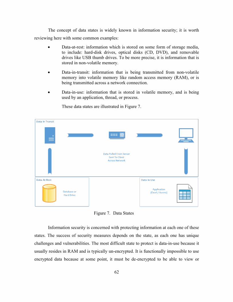
62
The concept of data states is widely known in information security; it is worth
reviewing here with some common examples:
Data-at-rest: information which is stored on some form of storage media, to include: hard-disk drives, optical disks (CD, DVD), and removable drives like USB thumb drives. To be more precise, it is information that is stored in non-volatile memory.
Data-in-transit: information that is being transmitted from non-volatile memory into volatile memory like random access memory (RAM), or is being transmitted across a network connection.
Data-in-use: information that is stored in volatile memory, and is being used by an application, thread, or process.
These data states are illustrated in Figure 7.
Figure 7. Data States
Information security is concerned with protecting information at each one of these
states. The success of security measures depends on the state, as each one has unique
challenges and vulnerabilities. The most difficult state to protect is data-in-use because it
usually resides in RAM and is typically un-encrypted. It is functionally impossible to use
encrypted data because at some point, it must be de-encrypted to be able to view or

63
modify. This information is usually the initial target of attackers as it is “on the surface”
and with the right tools can be easily accessed. However, this often requires physical
access to the machine with the information, as once it leaves the application or RAM, it
will be encrypted.
Data-in-transit is vulnerable to interception, by any number of man-in-the-middle
type attacks or spoofing. If one wants to ensure the security of the information, then it
must be encrypted, otherwise it is as good as if the hacker was invited onto the network.
However, encryption is not free and comes at price. First, many encryption algorithms
use a technique called padding to ensure chunks of data are of the same size. Second, it
takes a finite amount of time to run the encryption/de-encryption algorithm so that there
is time before transmission to “package” the message, and then time on the receiver end
to “unpack” the message from the encryption. The time intervals required for this process
are small (microseconds), though these fractions of seconds compound quickly for a large
messages.
Data-at-rest is the most common state the average computer user thinks of when
discussing information security concerns. The reasoning is simple – everyone knows that
information is stored on or in something, though this understanding may recede with the
growing prevalence of the “cloud.” As an aside – “the cloud” is no different than storing
files on a shared-drive, just the implementation is slightly different and the mechanisms
are more obscured. Given this understanding, it is fairly intuitive to understand the desire
to protect data while it “just sits there.” Much like a file cabinet in an office that contains
sensitive files; one does not want just anybody coming in and browsing through the files.
Encryption for data-at-rest does not add any more overhead from encrypting data-in-
transit, if the files are stored directly. Otherwise, there will be a slight delay before
writing so that the files may be encrypted and one can expect that files sizes will be
slightly larger than the same file in plaintext. The primary vulnerabilities for data-at-rest
are theft and destruction. Files written to storage media can be copied to another volume
and then an attacker can attempt to crack them at leisure. Because these files are non-
volatile, and are not being transmitted, the temporal aspect in capturing this type of
information is diminished.

64
How far into a system an adversary can get will determine how much information
they are able to view and subsequently steal. This is a real risk for an autonomous vehicle
because by design, it needs external communication ports and will likely be storing some
amount of data onboard for further analysis or processing. While the risk of interception
is ever present, it can be mitigated through encryption, with the understanding that it
comes at a cost. Additionally, measures can be taken to secure the information that
resides on the platform. However, the best way to prevent the adversary from gaining
information is for it not to be there. The designer in conjunction with the stakeholders
needs to consider carefully what information is gathered and stored aboard the vessel.
Given sufficient time and resources, a determined adversary will be able to crack most
security and encryption protocols, so the goal is to delay them as long as possible to
ensure that whatever information they do recover is sufficiently old as to not provide a
tactical or strategic advantage, to include gathering information on the collection
mechanisms or processes.
In short, the following is recommended: Autonomous vehicles, especially those at
risk for isolation and therefore capture, should follow computer security industry good
practices to prevent the interception and modification of information during any state of
use. Failing that, it is imperative that robust checks are performed on mission critical
information to ensure authenticity and non-repudiation.
3. Communications (COMSEC)
This USV will not need to use voice circuits, but it will need to transmit/receive
information on data circuits. The goal of this USV design is to keep all the classified
sources of data aboard the mother ship/base station and not on the individual USVs; this
allows them to be more expendable and alleviates some of the concerns surrounding an
adversarial capture of one of these units. However, even if the data itself is unclassified,
there is no need for an adversary to be able to see it plainly. Therefore, most data going to
and from the USV should be encrypted compatible with the designated classification
level required for the type of data being transmitted.

65
Special consideration is required in the design process to ensure that the USV’s
communication systems will be compliant with standing COMSEC policy. Additionally,
it will be necessary to consider how to implement the ability to “zero-ize”/erase onboard
communications gear to ensure the encryption keys do not become compromised by an
adversary. This level of encryption protects data while in transit, but it does come at the
price of increased amounts of data needing to be transmitted. Most encryption algorithms
carry a small data overhead depending on how they divide data into chunks. While this
overhead is generally small for Internet applications, it may be more restrictive for
vessels that have limited bandwidth and connectivity.
4. Operational
Operational security (OPSEC) is a set of security concerns that can impact the
successful completion of a mission. The most well-known phrase in the OPSEC
community is, “Lose Lips Sink Ships,” coined during WW2 to remind service members
and citizens to be mindful of their discussions about sensitive information. This notion
carries over to the electromagnetic spectrum as one can never be too sure of who is
listening to their electronic conversations. This is germane because the USVs in this
system are not fully autonomous and will require periodic communications back to a
controlling station.
A radio frequency broadcast signal in the UHF/VHF band is often transmitted
Omni-directionally and therefore is subject to intercept by any receiver in the line-of-
sight of the radio wave. It is possible to use beamforming techniques to make a
transmission more directional, though it then becomes important that the intended
receiver is oriented correctly to pick up the transmission. This is often difficult to achieve
with moving platforms as it requires both platforms to be synchronized with each other, a
problem whose difficulty increases greatly with an increase in degrees of freedom of
movement. RF data transmission is useful for LOS operations, but is often more costly
and challenging for over-the-horizon (OTH) transmissions. Even if the content of the
transmissions is encrypted, that fact that a station is transmitting provides valuable
intelligence to an adversary. For example, if an adversary is monitoring a region and

66
notices an absence of visible maritime traffic, but it sees a spike in RF transmissions from
this same region, then a reasonable conclusion is that there is something there that is
either camouflaged or is too small to be ordinarily detected.
To alleviate the concerns with LOS communication one may choose to use a
lower frequency signal that can bounce through the atmosphere or a highly directional
transmitter may be chosen. Often, this transmitter comes in the form of a satellite antenna
that is oriented to a satellite in orbit. While offering more security, it is not without its
drawbacks including limited quantities of communication slots available for assignment.
Just because a unit wants to use a satellite, does not mean the resources will be made
available to them for their use. Another alternative to RF transmissions is an acoustic
modem though they are still subject to counter detection by a submerged listening
platform.
5. Physical
The physical security and safety of the USV system is important to the safe and
effective employment of this system. With the exception of ACTUV/Sea Hunter, most
USVs are quite small in comparison to warships. This small size makes then vulnerable
to harassment, tampering, theft, and destruction by virtually every manned platform.
While this issue could be dismissed as an engineering or policy issue, it is fundamentally
a software issue as well. Upon detection of some sort of disruption event, the USV needs
to take immediate action to ensure the security of its onboard data, encryption keys, and
overall safe operation to include the notification of the C2 module that the USV is being
assaulted.
a. Anti-Theft / Anti-Tamper
The relatively small size of most USVs makes them vulnerable to threats that
would not concern most other warships. Specifically, because of their size, they are more
likely to be stolen by those seeking to sell the platform on a black-market, pilfer parts, or
vandalize it for the sake of amusement [29]. Additionally, these platforms would be more
at risk for detainment and possible physical intrusion attempts by an adversary.

67
Therefore, it is necessary for the USV to detect when it is being interfered with and take
appropriate actions.
A possible scenario is that an adversary vessel comes upon one of the USVs and
then decides to bring it aboard in an attempt to sabotage the USV. The easiest way to
detect this kind of tampering would be to have a temperature probe on the bottom of the
USV that if it should be exposed to free air would register it has been removed from
water. In case the USV got flipped over by wave action, then onboard acceleration
sensors should have detected the roll movement and reset the Out-of-water timer.
In the same scenario, if the adversary attempts to open the outer shell of the USV
without proper authorization, then it should register this and immediately delete all log
files, encryption keys, and send a transmission to the C2 module that it has been captured.
These scenarios highlight a need to have a robust physical intrusion detection system that
will preemptively clear all stored data, the assumption is that it is better to have to
recreate data from a backup then to allow data to fall into an adversary’s possession.
b. Legal Issues
Rhetorical question: Is a USV considered a sovereign military vessel, subject to
all the rights and privileges bestowed upon active commissioned warships, or is it simply
a piece of property, like a wrench or a rifle? Does this change when a nation commissions
a USV into its roster? A partial answer to this question is found in [30], which are the
remarks by Deputy Secretary of Defense Bob Work. In his remarks, he suggests that the
Navy should consider vehicles like the Sea Hunter to be “warships” not “drones.” One
can quibble over the semantics, but the idea here is that a warship is a “warship” whether
it has a crew or not. If this is the case, then one can speculate that the laws that apply to
crewed warships should also apply to non-crewed warships.
This leads to a troubling thought. If an unmanned vehicle is considered a
“warship,” then will the United States go to war or retaliate against another state should
they sink or otherwise damage the vessel? The author posed this question in an email to
the notable CAPT Wayne Hughes, author of Fleet Tactics and Costal Combat, who was

68
quick to point out that asking what a response would be is the wrong question. Instead he
suggested the following:
Instead of saying, “what would be our likely response” the first question is “what are our choices?” Not the choices listed [interpret attack on the USV as an attack on a sovereign warship, treat attack like vandalism, or ignore the attack] which are wannabes. First comes what we can do, second comes what we should do. [31]
The resolution to this question is important for designers, because it will influence
aspects of the design, particularly evasion and self-defense. If the vessel is a considered a
“warship,” then it needs to take all reasonable actions to avoid capture and to defend its
self. However, where does one draw the line on defense, how hard should the USV fight
for its survival or freedom? These are questions better left to other professions to answer.
B. MANPOWER
Manpower represents one of the largest variable costs associated with
implementing this software and probably one of the hardest to accurately predict. The
software, once developed, has a negligible reproduction cost, though a non-trivial one-
time setup cost will apply. Code maintenance will also be another variable cost, though if
managed properly will be predictable. To make this software effective, it needs to be able
to save the customer money that it would use on other assets. It is my belief that this
system could save thousands of dollars that are normally spent on expending non-
reusable sonobuoys or operating maritime air assets. Ideally, this system would also
allow you to save on the amount of people being used to operate and maintain the system
or enable better ASW coverage with the same number of people. This becomes a sticking
point.
In Human-Robot Interactions in Future Military Operations, there are two essays,
[4] and [32], that touch at the heart of this matter that almost appear to be both
complimentary and contradictory. In the first essay, titled The Safe Human-Robot Ratio,
the authors propose a ratio they believe provides the minimum number of people to
operate an unmanned system and still be safe. This ratio is defined as Nh = Nv + Np + 1,
or plainly: The number of humans (Nh) required to safely control an unmanned system is

69
equal to the number of vehicles (Nv) plus the number of payloads (Np) plus one [5]. The
authors use a lone, single-payload UAV as their base example. This platform, by their
ratio would require three humans to safely operate. During their research they saw that
most unmanned systems break down human tasks into three major roles: pilot, mission
specialist, and flight director/safety observer. The pilot’s goal was primarily to ensure
that the aircraft did not collide with any objects and to be in a position that allowed the
Specialist to use their sensor to observe the mission area. The director was responsible for
keeping overall situational awareness of the larger mission, and to integrate what the
specialist was seeing and what the pilot was seeing.
To apply the above equation to this project requires a little more refinement.
Specifically, the constitution of a payload is left undefined, and so for our purposes let us
define it. Conservatively, a payload could be each of the major sensor packages, so that
would be sonar, radar, FLIR. Less conservatively, one could separate the sensors into
broad areas of Acoustic, and Non-Acoustic, and then assume that the operator would not
be focusing on FLIR at the same time as radar, and therefore one could safely combine
those activities. At this point, the total number of payloads is between two and three.
Now, applied to a squadron of say 16 USVs, that would be sixteen (16) USVs plus thirty-
two (32) payloads (2 x 16) plus one (1), results in a manpower requirement of forty-nine
(49). That is unacceptable, as that is about one-sixth the crew complement of a destroyer.
Clearly the equation does not scale well if one is considering employing multiple USVs.
In attempt to minimize this number a developer may suggest that automation is
the answer—that it is necessary to “increase the level of automation” to be able to
perform more tasks that would have been done by a human. This is fair reasoning, but it
can be problematic. First, one needs to understand how further automation is achieved,
and likely, in the case of robots and USVs, the answer comes in the form of Artificial
Intelligence. However, AI is not the panacea that one might make it out to be, as
previously asserted in earlier chapters, AI is nothing more than fancy software. At the
base level it is operating on a set of rules that human developers defined, or through other
software, allowed the AI agent to define. It should be obvious that this path inherently

70
leads to errors, some of which may be quite insidious and not manifest under normal test
and evaluation conditions.
The essay presented in [32], Lessons Learned from Human-Robot Interactions on
the Ground and in the Air, discusses how automation is not the answer for reducing the
amount of people in the loop. The salient point in this discussion is that it is flawed
reasoning to believe that removing the human from “the loop” will result in a decrease in
errors. Certainly errors related to human carelessness or incompetence may be avoided,
only to be replaced by a different set of problems. This problem set occurs when humans
have been removed from the decision making loop and are cast into a supervisory role
but are then required to intervene and take control of the USV during certain error states,
like an emergency. When this occurs, the human’s like of tacit situational awareness
means that the human is reacting far slower than they would have been if they had been
in control all along.
This argument complements another argument from the first essay of the same
document in which the authors of the safety ratio propose that seeing the problem of
automation as being similar to an Air-Traffic Control (ATC) scenario is fallacious. The
reasoning is that while an ATC may have many aircraft under their control, there is a
pilot-in-command of each aircraft who is in charge of dealing with local abnormal
conditions, to include emergency procedures. It is not as if the ATC will suddenly take
remote control of one of the aircraft and handle nuanced execution of procedures.
I present these points of view for the audience’s consideration, as they
fundamentally impact how many humans must be employed to operate multiple USVs.
My argument is mostly technical in nature, that it is possible to present information
necessary to execute the control of USV from a limited number of human interface
points. However, the determination as to whether or not that is a good idea will require
prototyping and testing to assess safety and performance under abnormal conditions.
C. TRUST
Trust is a rather broad issue when discussing automated systems, and is a current
philosophical question that the robotics community is wrestling with. Trust comes in

71
many forms: explicit trust is usually defined formally through a contract, which may be
physical or verbal, and the responsibilities are clearly delineated. Implicit trust derives
from explicit trust, in the way that we trust doctors or pilots. We are not party to their
actual qualifications, but we have implied and imparted trust to them based on their
station. In all situations trust is usually earned through the demonstration of some set of
actions that establishes confidence, but it can be quickly voided when decisions are made
that are counter to the understood norms. For instance, the trust in an airline pilot is
irrevocably lost if the pilot shows up to work drunk. Loss of confidence in professionals
is not solely confined to workplace incidents. The errors in judgment that professionals
make while away from the office also can cause a loss of trust. Professionals are expected
to behave a certain way both on and off duty, and when these expectations are not met,
their professional judgment abilities are called into question. Once this erosion begins, it
is hard to recover.
How then is this applicable to autonomous systems and robotics? First, through
test and evaluation and eventually acceptance testing, we establish confidence that
software will work correctly most of time, and that it will accurately report when it is not
working correctly. However, to ask a rhetorical question: what happens if the software
does not recognize when it is wrong, or fails to report the situation? Can you continue to
trust the software? Do you fire it, or revoke its license? Obviously it is hard to hold
software accountable, so the axe usually falls on a programmer or some other poor soul
involved in the development. Yet, in a system that is designed to go over the horizon and
to meet the enemy, we are placing a great deal of trust in the system in that it is reporting
back correctly. Also, we are putting a lot of faith in the programming that it can recognize
a fault, or when it is tampered with. However, this thought is not justified, as it is nearly
impossible for a machine to recognize that it has changed, and it is functionally
impossible to test every possible state a piece of complex software could be in.
D. MAINTENANCE AND UPKEEP
Designing with upkeep and maintenance, to include upgrades, in mind is part of a
fundamental course in programming. Most instructors who teach programming classes
72
will insist that their students diligently make comments about their code, and that even
without the comments, names of modules, functions, and variables should all be easily
understood. The idea is to have the code “talk” to another programmer without needing
the original designer present to represent their code. The concepts of object oriented
programming, along with modularity, are fundamental learning points in programming.
In fact, as projects increase in size and complexity, it becomes imperative that the design
team ensures that their work remains modular. The driver behind these ideas is in a word:
change. Requirements frequently change, APIs change, and even the nature of the
problem may change. Therefore, it is important to begin the design process with this idea
in mind—while the design team may be the creators; they certainly will not be the last
hands on the project.
When assessing the total cost of ownership of an unmanned system, the
consideration for software upkeep must be addressed. This aspect of software is often the
part of the iceberg that sits below the water, as it can cost a company half of the
procurement costs in maintenance over the life cycle of the software. Intel in [33],
estimates that over the course of supporting a software product, a 70% to 85% of the
TCO will be absorbed as support costs. Support includes patching, training, and upgrades
to the software system.
E. ARGUMENTS AGAINST AUTOMATION
There is an idiom that is apropos to automation-just because something can be
done, does not mean it should be done. There are multiple instances where automation
could assist the work that a human is doing, or could replace the human entirely.
However, there is a price paid in removing the human from the equation.
Humans are inherently lazy, it is not that we mean or desire to be slothful; it is
just that we have a tendency or predilection for procrastination and complacency. By
allowing a computer to perform certain tasks in a combat environment, a sailor may
become complacent with the output of the machine and fail to be on guard for errors. For
example, in the case of automated target tracking, when inexperienced crew members
rely too heavily on the computer, their practiced skills atrophy and they become
73
distracted by other tasks. This distraction can mean the difference between detecting a
submarine, and allowing the submarine to pass undetected to sink the HVU.
As we allow machines to perform more and more tasks for us, we cede control
over events and risk becoming passengers to our AI drivers. In combat, mistakes can be
fatal, and overly relying upon machines and software could be deadly. The victor of the
next major conflict will be the one who did not overly restrict their machines, but also did
not allow their human assets to become too reliant on those machines. Humans require
food, water, and shelter to survive; creative outlets and purpose to thrive [34]. An
autonomous system requires information for both. Restrict the information flow and you
starve the automaton.

74
THIS PAGE INTENTIONALLY LEFT BLANK

75
VI. FUTURE WORKS AND RECOMMENDATIONS
During the course of my research, I discovered many topics that could be
interesting for follow on research. It is with regret that I did not have time to pursue every
avenue and so I leave these bread crumbs for fellow scholars.
A. FUTURE WORK
1. Operating in Fully Degraded Communications Environments
One of the primary assumptions made during this design was that the proposed
USV system would be operating in a communications environment that was either fully-
permissive up to partially-degraded. The over-arching assumption being that the U.S.
would have the same control over the EM spectrum that we have had in previous
confrontations. Unfortunately, this is an unsafe assumption to make when considering
peer or near-peer adversaries. The People’s Republic of China is the country to most
recently demonstrate an (anti-satellite) ASAT capability and planners should consider
that they might freely export that technology to other countries. With ASAT capability,
one cannot assume that they will be able to use GPS and other satellite based
communications during a confrontation with these states. This has major implications for
a USV that relies on GPS, as they could become an effective mission-casualty at the
opening of hostilities. Further research is necessary to determine backup systems that can
be installed which do not overly encumber the platform. One recommendation is to use
an inertial navigation system, but a limitation with these systems is that they periodically
need to calibrate off a fixed position. Radar could be used to establish radar lines of
bearing if in close proximity to the coastline, and other OTH transmissions like LORAN
have been used in the past to help triangulation efforts. A significant vulnerability for this
platform, and the U.S. military as whole, is the over-reliance on GPS. Manned platforms
would be superior in this regard as they can fall back to paper charts if necessary, though
this too is becoming increasingly rare skill. Alternatives are necessary if the goal is to use
these systems the day after the GPS has been disrupted.

76
2. Sense Making for ASW
While exploring the material and the theory behind the Cynefin model, and
learning about organizational and operational complexity it occurred to the author that
applying the Cynefin model and other products from Creative-Edge may yield some
valuable insights into ASW. ASW is a domain that has atrophied and is slowly resurging
in Navy circles; however it would be beneficial to the organization to capture some of the
cognitive processes that go into fighting submarines that could improve the warfare area
in general, and enable smarter use of autonomous systems in particular.
3. Classification Issues
My proposed model includes pulling from the ACINT and SIGINT databases,
however to combine these abilities onto one system may make the system too classified
for operational use. The ideal mission system will have a classification of no higher than
SECRET. The basis for this recommendation is that higher classification level will make
the USV control system inaccessible to a large segment of the shipboard workforce.
Ultimately the USV module, the C2 module, and the HCI module do not require
knowledge on collection methods and sources, just the signatures. Coordination with
specialists in this field should help the designer avoid difficulty in this area.
4. User Interface Prototyping and Use Study
I made the claim that the Human Computer Interface or User Interface portion of
this system was one of the most critical components. The C2 module is certainly the
brains of the operation, but to the warfighter—it is and should be transparent. This makes
the HCI module the heart of the design. The only way for an operator to truly be able to
control multiple assets, is to have good situational awareness of where all their assets are.
This is impossible to accomplish with a muddled, non-intuitive, non-user friendly
interface. If the button-pusher has to think more about what sequence of commands are
that need to be issued versus just commanding, then the whole enterprise is lost and will
quickly sap value.

77
To this end, it is necessary to conduct a task analysis and rapid prototyping of
some UI mockups to start getting instant feedback from the end user. The closer the
controls can mimic triple-A video game design, the more intuitive the controls will be to
a user, and the payoffs will be noticeable: quicker time to train, minimized error rate,
higher situational awareness. However, the study must be commissioned and performed
to start capturing those data points.
5. Valuation Functions
Chapter IV, Section I, discussed assessing the value added by an autonomous
system. The author initially began work on developing an equation / process to try to
assign a measure of value to dissimilar UMS. One of the chief difficulties of this
approach was how to judge the value, other than monetary, of two different UMS
performing the same mission, but in different domains. For example, how does one
compare a USV for ASW against a UAV for ASW? The stakeholder wants to know what
system they should invest in, and presumably they have an idea as to which domain they
would prefer. Considering their needs, it could boil down to “it depends.” Consider a
more likely scenario: two USVs that are designed to perform the same mission,
developed by two different manufacturers and are roughly the same cost…which does
one choose, which is better? The answer would initially be “it depends” but one could
establish a set of benchmarks for the systems to tackle, and then depending on the result,
choose the best. Short of a decisive victor, it comes down to a qualitative or “gut”
decision. Ultimately, the idea was scrapped because it gets intractable quick, with not a
lot of “value added.” A consumer considering a car purchase is likely to buy from the
manufacturer that they have established a familiarity with over one they have not; the
exception being: a less familiar alternative is so greatly superior in quality or price as it
would be illogical to choose otherwise. The conclusion was that in the case of a clear
victor, no equation would help, and in the case where it is inconclusive, then a quasi-
scientific numerical approach would not sway the gut of a stakeholder.

78
6. USV Group Leadership
In human organizations with hierarchal structures a leader usually does not have
direct communication with more than three to six individuals. While a single leader may
be responsible for hundreds or thousands of people, that leader usually does not have
meaningful direct contact any more than the three to six. As previously discussed, this is
likely due to limits on human capabilities for multi-tasking. This type of organization
scales pretty well as demonstrated by military organizations. The question becomes, does
an organization like this help when dealing with multiple USVs.
The benefits to selecting a single USV to be the leader of multiple USVs, like in a
formation, are many. First, selecting a single unit to be a leader allows the human
operator to abstract away the rest of the units and then deal with a grouping collectively
by issuing instructions to a single unit. That unit then has the burden of parceling up
instructions—a problematic situation. However, if the leader acted as a relay, it could
communicate with units that were a further distance from the main communications node
and act as a place for those units to store and forward messages back to the main entity.
Other issues also arise such as how do you initially select a lead? Does the lead
remain static? What happens if the leader can no longer remain with the group or is
destroyed?
B. CLOSING
Unmanned systems of all shapes and sizes are the new normal of modern warfare.
As a country, we can ill afford to lose the advantages we have in unmanned and
autonomous systems, and we must strive to close the gaps between us and our
competitors. Through this work, it has been the motivation to help support those who
develop the next generation of unmanned vehicles for the war-fighter. It is the author’s
hope that other scholars will pick up where he left of, and continue to tease out ways of
achieving the ultimate goal of many unmanned vehicles under the control of a single
human.

79
LIST OF REFERENCES
[1] Department of the Navy, “The Navy unmanned surface vehicle (USV) master plan,” Washington, DC, 2007. [Online]. Available: http://www.navy.mil/navydata/technology/usvmppr.pdf. [Accessed 24- Aug- 2016].
[2] S. Savitz, National Defense Research Institute and United States Navy, U.S. Navy employment options for unmanned surface vehicles (USVs). Santa Monica, CA.: RAND Corporation, 2013.
[3] S. Russell, P. Norvig and E. Davis, Artificial Intelligence, 3rd ed. Upper Saddle River, NJ: Prentice Hall, 2010, p. 2, 5 ,34–35, 37, 40.
[4] R. Murphy and J. Burke, “The safe human-robot ratio,” in Human-Robot Interactions in Future Military Operations, 1st ed., M. Barnes and F. Jentsch, Ed. Burlington, VT: Ashgate Publishing Co., 2010, pp. 31–48.
[5] A. Oliveira, “Software architecture for autonomous vehicles,” M.S.C. thesis, Dept. Elect. and Comput. Eng., Instituto Superior Tecnico, Lisbon, Portugal, 2009.
[6] V. Berzins and Luqi, Software Engineering with Abstractions. Reading, MA: Addison-Wesley, 1991.
[7] B. Harris, “Hitler’s Lost Sub: 400 Years of Subs (1580-1861),” PBS, 2016. [Online]. Available: http://www.pbs.org/wgbh/nova/lostsub/hist1580.html. [Accessed: 24- Aug- 2016].
[8] “United Nations Convention on the Law of the Sea (UNCLOS)—Table of Contents,” United Nations, 1982. [Online]. Available: http://www.un.org/Depts/los/convention_agreements/texts/unclos/UNCLOS-TOC.htm. [Accessed: 18 July 2016].
[9] Naval Meteorology and Oceanography Command, Fleet Oceanographic and Acoustic Reference Manual. Stennis Space Center, MS: Naval Oceanographic Office, 1986.
[10] H. Young, R. Freedman, A. Ford and F. Sears, Sears and Zemansky’s University Physics, 11th ed. San Francisco: Pearson Addison Wesley, 2004, p. 1252.
[11] SH-60B Naval Aviation Technical Information Product (NATIP), NTRP 3–22.4-SH60B, U.S. Dept. of the Navy, Patuxent River, MD, 2010.

80
[12] A. Cunningham and B. Thomas, “Target motion analysis visualization,” in 2005 Asia-Pacific symposium on information Visualization: 2005, Sydney, Australia, Darlinghurst, Aus.: Australian Computer Society, 2005.
[13] P-8A Poseidon. (2016). NAVAIR [Online]. Available: http://www.navair.navy.mil/index.cfm?fuseaction=home.display&key=CFD01141-CD4E-4DB8-A6B2-7E8FBFB31B86. [Accessed: 26- Mar- 2016].
[14] How can we secure 141 million square miles of ocean? (2016). Leidos. [Online]. Available: https://www.leidos.com/perspectives/nearly-undetectable-submarines-threaten-u-s-ships-and-shipping#tab/tab3. [Accessed: 26- Mar- 2016].
[15] Liquid Robotics, Inc., “LR-ProductSheet-SHARC3-3.6_web.pdf,” 2016.
[16] Joint Targeting, JP 3–60, U.S. Joint Chiefs of Staff, Washington, DC, 2013, 2.2.g.
[17] D. Larter. (2015, May 22). Saving Sammy B: A frigate’s heroic legacy. Military Times, [Online]. Available: http://www.militarytimes.com/story/military/2015/05/22/samuel-b-roberts-frigate-legacy-1988-mine-report/27593135/. Accessed: Sep. 3, 2016.
[18] “Agent.” Merriam-Webster.com. [Online]. Available: http://www.merriam-webster.com/dictionary/agent. [Accessed 24- Aug- 2016].
[19] D. Snowden. (2010). Cynefin Framework [Online]. Available: https://fast.wistia.net/embed/iframe/3f0294bdc5?videoFoam=true. Accessed: Sep. 5, 2016.
[20] E. Evans, Domain-Driven Design: Tackling Complexity in the Heart of Software, 11th ed. Boston, MA: Addison-Wesley Educational Publishers, 2003.
[21] W. Cook. (2015, Aug.). “The problem,” in the traveling salesman problem. [Online]. Available: http://www.math.uwaterloo.ca/tsp/problem/index.html. Accessed: Sep. 14, 2016.
[22] Navigation Rules and Regulations Handbook, U.S. Coast Guard, Washington, DC, 2015.
[23] Luqi and E. Lednicky, “USV ASW employment part I,” Naval Postgraduate School, Monterey, CA, Tech. Rep., Sep. 2016.
[24] Luqi, “USV ASW employment part II,” Naval Postgraduate School, Monterey, CA, Tech. Rep., Sep. 2016.
[25] H. Palmer and M. Thronburgh, Adobe’s Real Time Messaging Protocol, 1st ed. San Jose, CA: Adobe Systems Incorporated, 2012.

81
[26] Platform tech specs. (n.d.). Livestream. [Online]. Available: https://livestream.com/platform/tech-specs. Accessed: Sep. 15, 2016.
[27] G. Godin. (2016). Virtual Desktop. [Online]. Available: http://store.steampowered.com/app/382110/. Accessed: Sep. 25, 2016.
[28] N. Ingebrigtsen. (2007). The differences between data, information and knowledge [Online]. Available: http://www.infogineering.net/data-information-knowledge.htm.
[29] D. DeKok. (2015, Aug. 3). No plans to probe hitchhiking robot vandalism: Philadelphia police. Reuters [Online]. Available: http://www.reuters.com/article/us-usa-robot-pennsylvania-idUSKCN0Q826G20150803.
[30] B. Work, “Remarks at the ACTUV ‘Sea Hunter’ christening ceremony,” presented at Sea Hunter christening ceremony, Portland, OR, 2016.
[31] S. Fahey, private communication, Jun. 2016.
[32] N. Cooke and R. Chadwick, “Lessons learned from human-robotic interactions on the ground and in the air,” in Human-Robot Interactions in Future Military Operations, 1st ed., M. Barnes and F. Jentsch, Ed. Burlington, VT: Ashgate Publishing Company, 2010, pp. 357-369.
[33] Y. Ghazizadeh. (2009, Feb. 25). Total cost of ownership: factors to consider [Online]. Available: https://software.intel.com/en-us/articles/total-cost-of-ownership-factors-to-consider.
[34] S. McLeod. (2016). Maslow’s hierarchy of needs [Online]. Available: http://www.simplypsychology.org/maslow.html.

82
THIS PAGE INTENTIONALLY LEFT BLANK

83
INITIAL DISTRIBUTION LIST
1. Defense Technical Information Center Ft. Belvoir, Virginia 2. Dudley Knox Library Naval Postgraduate School Monterey, California