soc physical security evaluation
TRANSCRIPT

HAL Id: tel-03282313https://tel.archives-ouvertes.fr/tel-03282313
Submitted on 9 Jul 2021
HAL is a multi-disciplinary open accessarchive for the deposit and dissemination of sci-entific research documents, whether they are pub-lished or not. The documents may come fromteaching and research institutions in France orabroad, or from public or private research centers.
L’archive ouverte pluridisciplinaire HAL, estdestinée au dépôt et à la diffusion de documentsscientifiques de niveau recherche, publiés ou non,émanant des établissements d’enseignement et derecherche français ou étrangers, des laboratoirespublics ou privés.
SoC physical security evaluationThomas Trouchkine
To cite this version:Thomas Trouchkine. SoC physical security evaluation. Micro and nanotechnologies/Microelectronics.Université Grenoble Alpes [2020-..], 2021. English. NNT : 2021GRALT018. tel-03282313

THÈSEPour obtenir le grade de
DOCTEUR DE L’UNIVERSITE GRENOBLE ALPES
Spécialité : NANO ELECTRONIQUE ET NANO TECHNOLOGIES
Arrêté ministériel : 25 mai 2016
Présentée par
Thomas TROUCHKINE
Thèse dirigée par Jessy CLÉDIÈRE Université Grenoble Alpes et codirigée par Guillaume BOUFFARD, Agence Nationale de la Sécurité des Systèmes d’Information
préparée au sein du Laboratoire CEA/LETIdans l'École Doctorale Electronique, Electrotechnique, Automatique, Taitement du Signal (EEATS)
Évaluation de la sécurité physique des SoC
SoC physical security evaluation
Thèse soutenue publiquement le 24 mars 2021,devant le jury composé de :
Monsieur Jessy ClédièreCEA-E5, Université Grenoble Alpes, Directeur de thèseMadame Karine HeydemannMAITRE DE CONFERENCE, Laboratoire d’Informatique de Paris 6, RapportriceMonsieur Philippe MaurineMAITRE DE CONFERENCE, Laboratoire d’Informatique, de Robotique etde Microélectronique de Montpellier (LIRMM), RapporteurMadame Clémentine MauriceCHARGE DE RECHERCHE, CNRS, CRIStAL, Université de Lille, ExaminatriceMadame Marie-Laure PotetPROFESSEUR, ENSIMAG, Examinatrice et Présidente du JuryMonsieur Jean-Max DutertrePROFESSEUR, École des Mines de Saint Étienne, ExaminateurMonsieur Patrick SchaumontPROFESSEUR, Worcester Polytechnic Institute, ExaminateurMonsieur Lilian BossuetPROFESSEUR, Université Jean-Monnet, ExaminateurMonsieur Patrick HaddadDOCTEUR INGENIEUR, ST Microelectronics, InvitéMonsieur Guillaume BouffardDOCTEUR, Agence Nationale de la Sécurité des Systèmes d’Information/Ecole Normale Supérieure, Invité, co-encadrant


A B S T R A C T
Since the democratization of mobile devices, sensitive operations likepayment, identification or healthcare, usually done using securityevaluated smartcards, are handled by these devices. However, mo-bile devices neither are designed for security nor security evaluated.Therefore, their resistance against powerful attacks, like physical at-tacks is questionable.
In this thesis, we aim at evaluating the security of mobile devicesagainst physical attacks, in particular perturbation attacks. These at-tacks aims at modifying the execution environment of the device to in-duce bugs during its computation. These bugs are called faults. Thesefaults can compromise the security of a device by allowing the crypt-analysis of its secret or forcing an unauthorized authentication forinstance.
Mobile devices are powered by modern processors, which are theheart of this work, and are never evaluated against fault attacks. How-ever, our knowledge about fault attacks on smartcards is not rele-vant as the processors powering smartcards are way less complex,in terms of number of modules, technology node and optimizationmechanisms, than modern processors.
Regarding this situation, we aim at providing rationals on the se-curity of modern processors against fault attacks by defining a faultcharacterization method, using it on representative modern proces-sors and analyzing classical security mechanisms against the charac-terized faults.
We characterized three devices, namely the BCM2837, BCM2711b0
and the Intel Core i3-6100T against fault attacks using two differentinjection mediums: electromagnetic perturbations and a laser. We de-termined that these devices, despite having different architecture andusing different mediums are faulted in similar ways. Most of the time,a perturbation on these devices modify their executed instructions.
As this is a powerful fault, we also analyzed classical security mech-anisms embedded in such devices. We successfully realized a dif-ferential fault analysis on the AES implementation of the OpenSSLlibrary, which is used in every Linux based operating system. Wealso analyzed the Linux user authentication process involved in thesudo program. This work highlights the lack of tools to efficiently ana-lyze Linux programs, which are rather complex with dynamic linkingmechanisms, against fault attacks.
i
R É S U M É
De nos jours, nos appareils mobiles sont utilisés pour réaliser desopérations sensibles telles que du paiement, de l’identification ou lagestion de services santé. Historiquement, ces opérations sont réal-isées par des appareils conçus et évalués pour résister à diverses at-taques: les éléments sécurisés. En revanche, les appareils mobiles sontconçus pour fournir la meilleure performance possible et ne subissentaucune évaluation de sécurité. Cet état de fait interroge sur la résis-tance de ces appareils face aux attaques classiques contre lesquellesse protègent les éléments sécurisés.
Parmi ces attaques, nous nous proposons, dans cette thèse, d’étudierles attaques par perturbations. Ces attaques consistent à modifier lesconditions d’exécution du circuit ciblé afin d’induire des erreurs dansson fonctionnement. Ces erreurs volontaires, communément appeléesfautes, permettent de créer des failles dans la cible pouvant allerjusqu’à la cryptanalyse d’un algorithme de chiffrement ou l’authentifi-cation d’un utilisateur non autorisé.
Bien que ces méthodes d’attaques soient connues et étudiées surles éléments sécurisés, les appareils modernes reposent sur des pro-cesseurs modernes présentant des différences par rapport aux pro-cesseur des éléments sécurisés. Cela peut être le nombre de modulequ’ils embarquent, leur finesse de gravure ou des optimisations.
L’impact de ces différences sur la sécurité des processeur n’a pasété étudié en prenant en compte la possibilité d’induire des fautes.C’est ce que nous réalisons dans cette thèse. Nous définissons uneméthode permettant de caractériser les effets de perturbations surun processeur moderne que nous appliquons sur trois processeursreprésentatifs des appareils existants: le BCM2837, le BCM2711b0 etl’Intel Core i3-6100T. Nous avons également utilisés deux moyensde perturbation classiques: l’injection d’onde électromagnétique etl’utilisation d’un laser. L’étude de ces cibles, en variant les moyensd’injections de faute, nous a permis de déterminer qu’elles réagissenttoutes de manière similaire aux différentes perturbations malgré leurdifférentes architectures. L’effet le plus marquant étant la modifica-tion des instructions exécutées.
Ce type de faute est très fort car il permet de modifier une par-tie du programme exécuté pendant son exécution. Vérifier le pro-gramme avant de l’exécuter ne protège en rien face à ce type defautes, par exemple. C’est pourquoi nous avons également étudié larésistance des mécanismes de sécurité présents dans ces cibles faceà ce type de faute. Nous avons notamment réussi à cryptanalyserl’implémentation de l’algorithme de chiffrement AES de la biblio-thèque OpenSSL, très utilisé dans les systèmes utilisant Linux. Nousavons également étudié la résistance du mécanisme d’authentificationdes utilisateurs d’un système Linux en regardant le programme sudo.Cette étude nous a, en particulier, révélé que la communauté manque
ii

d’outils efficace pour analyser ce type de programmes face aux fautes.En effet, les programmes s’exécutent dans un environnement Linuxbénéficient de nombreux mécanismes liés au noyau Linux qui rendentl’exécution d’un programme difficile à étudier.
iii

So what if you fail once or twice ?I don’t even know how many thousand times I failed to control my rage.
— Dragon Sin of Wrath, Meliodas (The Seven Deadly Sins)
R E M E R C I E M E N T S
S’il est bien une chose que tous les efforts du monde ne peuventégaler, c’est l’inspiration, l’aide et les conseils des personnes que nouscroisons au cours de notre vie.
Et parce que cette thèse présente une partie des efforts que j’aifourni durant ces trois dernières années, je tiens à dédier ce chapitre àces personnes qui m’ont donné de quoi arriver jusqu’ici. Il est difficilede mettre un mot, ou une définition sur ce que j’ai reçu, mais je saisque cela m’a énormément aidé.
Avant toute chose, je tiens à remercier mon jury de thèse, Mme.Karine Heydemann, M. Philippe Maurine, Mme. Clémentine Maurice,Mme. Marie-Laure Potet, M. Jean-Max Dutertre, Mr. Patrick Schau-mont, M. Lilian Bossuet et M. Patrick Haddad, qui, non seulementd’accepter de juger de mon travail, m’ont régulièrement aidé à traversdes critiques et des échanges sur mes travaux qui ont souvent portéleurs fruits.
Je remercie également mon directeur de thèse, M. Jessy Clédière,pour son aide et ses conseils tout au long de la thèse malgré la dis-tance qui nous sépare.
Et je remercie très chaleureusement mon encadrant, et collègue, etdésormais ami, M. Guillaume Bouffard. Le remercier pour son en-cadrement ne lui rend pas justice tant son investissement dépassecelui d’un encadrant, nous avons pu échanger, partager et nous en-traider tellement souvent que je ne peux tout énumérer ici. Il metarde de pouvoir retourner partager des bières en terrasse avec toi !
D’autres remerciements, très forts, se doivent d’aller à mes parentsEmmanuelle et François. Leur soutien ne se matérialise pas par desconseils sur la sécurité des processeurs ou sur une critique de la méth-ode de caractérisations des fautes mais par des choses bien plus inde-scriptibles pour moi. Ils ont été, sont et seront un soutien qui apportebien plus que ce que je ne peux décrire. Que ce soit un foyer famil-ial quand le moral est en baisse ou un stock de papier de toilette enpleine pandémie.
Une dédicace toute spéciale va à ma petite sœur, Julie. Encore unefois, décrire la nature exact de l’aide qu’elle m’apporte est très diffi-cile, elle a ce magnifique défaut d’être incapable de voir mes défauts,mes erreurs et mes échecs et sera toujours une bonne raison de faireen sorte que je n’ai rien de tout ça.
Ma prochaine pensée va à l’ensemble des professeurs que j’ai eudurant ma scolarité. J’ai eu l’occasion de m’essayer à l’exercice del’enseignement et j’ai bien compris que certains m’ont apporté plus
v

que cela. Je pense en particulier à Livia, Khalid et Francesco, mes pro-fesseurs de collège lorsque j’étais en Roumanie, sans savoir pourquoi,c’est à partir de cette période que j’ai commencé à vraiment m’intéresseraux sciences. Je tiens également à remercier mes professeurs de lycéepour m’avoir poussé sur la voie vers les écoles d’ingénieurs. Je remer-cie également, justement, ces professeurs que j’ai rencontré, en écoled’ingénieur, à Gardanne, et qui m’ont donné ou dévoilé cette fibrepour la micro-électronique et m’ont un peu poussé vers la thèse, jepense en particulier à M. Jean-Baptiste Rigaud.
J’en profite pour remercier mes camarades de promotion, avec quij’ai passé des moments uniques que ce soit en cours, en soirée ou enassociation. Je remercie en passant l’équipe du mandat 9 de M-GaTEque j’ai eu la chance de présider pendant un an et avec lesquels j’aibeaucoup appris.
Naturellement, mes prochains remerciements vont envers mes amis,que je ne remercierai jamais assez et qui m’apportent énormément. Jepense aux Maissois, Benoît, Gaëlle et leur fille Maëlyne (aka. Choupette!) dont j’ai la chance d’être le parrain. Vous formez une famille ex-ceptionnelle et je suis heureux d’en être un membre invité ! Je re-mercie également mes camarades judokas, Rodolphe et Sylvie, dontl’exigence et la douceur s’équilibrent parfaitement, Kathleen qui ahérité des deux, Yann et Sylvain, les frangins qui croquent la vie àpleine dent, Jérôme qui parcourt le monde, Rémi à la volonté infail-lible avec qui j’ai eu la chance de passer les kata, André qui nous aformé pour ces kata, la famille Mota, l’équipe cadet: Killian, Sylvain,Morgan et Alexandre, la famille Reytier: Patrick et Brigitte, Fabien,Morgane (aka. Meuh) ainsi que Kévin, Kelly et Maiwen qui m’ont of-fert un vrai refuge avec des barbecues, des soirées et des séances dewakeboard ou de voile mémorables. Vous m’avez énormément appris,tant sur l’importance des amis et d’une équipe, que sur l’exigence per-sonnelle ainsi que l’investissement physique et psychologique pourprogresser, et évidemment la volonté de se battre malgré ce qui nousfait face. Tout ceci m’a servi, pour la réalisation des travaux présentédans cette thèse, mais pas seulement. Parmi les Maissois qu’il reste,je tiens à remercier mes camarades de soirées, où nous avons tantôtmontrer nos talents au Beer-Pong tantôt refait le monde, merci Florian,Jérémy B. et Juliette (le couple parfait !), Jérémy T., Adeline et Marjo-laine, ma super voisine avec qui je courrais après le bus pour aller aulycée.
Une pensée particulière va envers Jean, qui m’a appris à jouer dela guitare mais qui au final m’a partagé bien plus que de la technicitésur un instrument. C’est une vrai philosophie de vie, mise à l’épreuvepar la maladie, qui m’a été transmise et que je veux honorer.
Parmi les pensées particulières, il y en a pour ces amis de longuedate, ces relations qui survivent à la distance et au temps, je penseen particulier à Thomas L., Antoine et Thibaut Tai. Savoir que vousêtes quelque part, plus ou moins dans le coin, et qu’on partagera denouveaux de bons moments ensemble est toujours bon pour le moral.J’ai hâte d’entendre tout ce que vous avez à me raconter !
vi

Et puisque que nous en sommes aux bons amis, je tiens à remercierdes bandes particulières. Les Maissois et les judokas, que j’ai déjà eul’occasion de remercier. Merci aux 6 doigts de la main (ordre de cheva-liers encore meilleurs que les 7 pêchés capitaux), Arnaud le chanteur,Florian S. le sportif, Camille la motarde, Pierre (aka. Caillou) le fu-tur astronaute breton ! et Paul (aka. Skøll) le viking, pour votre bonnehumeur, votre soutien ainsi que les Skypéro ! Mention spéciale à Marieet Fanny, qui accompagnent deux d’entre eux dans la vie et qui megrillent (trop) facilement sur Among Us. Merci également à la DreamTeam, David, le chevalier au cœur pur, Guillaume, que j’ai déjà eul’occasion de mousser et Louiza, la plus grande adoratrice de planteset de chats au monde, vous êtes des collègues exceptionnels.
Je tiens à remercier également les Nakamas, qui m’ont fait décou-vrir le crossfit et dont la bonne humeur n’égale que l’énergie, que cesoit pour enchaîner les burpess, à la box ou dans mon salon, ou pourdévorer des barbecues et des raclettes. Mention spéciale aux coachs:Jérémy, Mickael et Édouard qui sont des exemples à suivre dans biendes domaines.
Enfin merci à la Légion Jedi, une superbe guilde avec laquelle j’aioccupé de nombreuses heures de confinement et de couvre-feu àrigoler tout en sauvant la galaxie !
Et pour finir, je remercie également l’ensemble de mes collèguesde l’ANSSI, et en particulier ceux du laboratoire de sécurité des com-posants, pour leur accueil, leur soutien, leur bonne humeur, les bièresle soir et les discussions polémiques. Merci Eliane (the boss), Patrick,Guenaël, Emmanuel, Karim, Ryad, Adrian, Guillaume, Boris, David,Louiza, Julien et Yoan.
vii


C O N T E N T S
i introduction 1
1 about cybersecurity 3
1.1 Cybersecurity problematic 4
1.2 Secure Devices Evaluation 4
1.3 ANSSI’s role in France 6
1.4 This thesis 6
2 study context 9
2.1 Introduction 10
2.2 Secure Elements 10
2.2.1 Architecture 11
2.2.2 Central Processing Unit (CPU) 12
2.2.3 Packaging 13
2.3 Systems On Chip 13
2.3.1 Architecture 15
2.3.2 CPU 17
2.3.3 Packaging 20
2.4 Multi-application system security 21
2.5 Conclusion 23
3 physical attacks 25
3.1 Side-channel attacks 26
3.1.1 Micro-Architectural Attacks 28
3.1.2 Side-Channel countermeasures 28
3.2 Invasive attacks 28
3.2.1 Reverse engineering 29
3.2.2 Focused Ion Beam 29
4 perturbation attacks 31
4.1 Genesis 33
4.2 Inducing a fault: injection mediums 34
4.2.1 Design considerations 34
4.2.2 Clock glitches 36
4.2.3 Voltage glitches 36
4.2.4 Temperature manipulation 37
4.2.5 Electromagnetic perturbations 37
4.2.6 Optical perturbations 39
4.2.7 Body biasing 41
4.2.8 X-Rays 41
4.2.9 Software induced perturbations 41
4.3 Characterizing a fault 44
4.3.1 Fault models 44
4.3.2 Fault analysis 46
4.4 Exploiting a fault 47
4.4.1 Fault attacks against multi-application systems 47
4.5 Countermeasures 56
4.5.1 Space redundancy 57
4.5.2 Operation duplication 57
ix

x contents
4.5.3 Infection countermeasure 58
4.5.4 Code hardening 58
4.5.5 Sensors 60
4.6 Conclusion on perturbation attacks 60
ii contribution 63
5 fault effect characterization on systems on chip 65
5.1 SoC modeling 66
5.2 Attacker model 66
5.3 Experimental method 67
5.3.1 Top-down approach 67
5.3.2 Target setup 68
5.4 Determining the faulted element 73
5.5 Conclusion 75
6 experimental work 77
6.1 Practical work setup 78
6.1.1 Attack benchs 78
6.1.2 Evaluated devices 81
6.1.3 Tools 85
6.2 BCM2837 characterization 91
6.2.1 Hot-spots maps 92
6.2.2 Analyzer results 94
6.2.3 Micro-architectural analysis using a test program 100
6.2.4 Micro-architectural analysis on a baremetal setupwith JTAG 104
6.2.5 Conclusion on the BCM2837 characterization 107
6.3 BCM2711b0 characterization 108
6.3.1 Hot-spots maps 108
6.3.2 Analyzer results 109
6.3.3 Conclusion on the BCM2711b0 characterization 113
6.4 Intel Core i3 characterization 114
6.4.1 Hot-spots maps 114
6.4.2 Analyzer results 116
6.4.3 Conclusion on the Intel Core i3-6100T 119
6.5 Characterization conclusion 119
7 fault model exploitability 121
7.1 DFA on the OpenSSL AES implementation 123
7.1.1 Source code location 123
7.1.2 Static analysis 124
7.1.3 Fault attack on the OpenSSL AES 126
7.1.4 DFA software 128
7.1.5 Conclusion on the OpenSSL AES DFA 132
7.2 Baremetal AES PFA [159] 132
7.2.1 PFA Result 132
7.2.2 Conclusion on the PFA on our baremetal AES 134
7.3 sudo authentication 134
7.3.1 Attack model 135
7.3.2 sudo analysis 135
7.3.3 Code analysis 141
7.3.4 Program setup 142

contents xi
7.3.5 Side channel analysis 144
7.3.6 Exploitation 145
7.3.7 Conclusion on the forced authentication 147
7.4 Analysis tools 147
7.4.1 The function analyzer 148
7.4.2 Fault simulator 149
7.5 Evaluation conclusion 151
iii conclusion 153
8 conclusion 155
iv appendix 159
a bcm2837 maps per fault model 161
b fault analyzer interface 163
c gdb analysis of sudo with debug symbols 167
d sudoers_policy_check() disassembly 169
e openssl aes aes_encrypt() round function (dis-sassembled) 171
e.1 OpenSSL AES round computation (Disassembled) 171
bibliography 173

L I S T O F F I G U R E S
Figure 1 Evaluation process actors (example with CommonCriteria (CC)) 5
Figure 2 Smartcard in a payment environment 10
Figure 3 Secure element architecture 11
Figure 4 Secure element CPU architecture 12
Figure 5 Secure element packaging 13
Figure 6 ISO7816 pins 13
Figure 7 Smartphone environment 14
Figure 8 System on Chip architecture 15
Figure 9 Cache incoherence after a module updated adata in its dedicated cache memory 16
Figure 10 Modern CPU architecture 17
Figure 11 Out-of-order execution principle 19
Figure 12 Package on package 20
Figure 13 BGA grid on a PCIe chip 21
Figure 14 Multi-application system security dependencies 23
Figure 15 Current in a Complementary MOS (CMOS) log-ical inverter gate for different inputs. 27
Figure 16 Perturbation attack analysis and evaluation pro-cess 32
Figure 17 Stimuli able to perturb a digital device 34
Figure 18 Timing constraints on the input for a DFF tobehave correctly 35
Figure 19 Timing constraint in digital devices 35
Figure 20 Clock glitch effect on a D Flip-Flop (DFF) 36
Figure 21 How ElectroMagnetic (EM) sampling faults oc-cur [71] 38
Figure 22 ST Microelectronics M27C256B Erasable Pro-grammable Read-Only Memory (EPROM) 39
Figure 23 Laser effect on a CMOS logical inverter out-putting a logical zero 40
Figure 24 One-bit DRAM memory cell 42
Figure 25 DRAM line activation and copy in the row buffer 43
Figure 26 PMS supplying the power voltage and clock tocores and module of a SoC 43
Figure 27 Fault propagation through digital devices ab-straction layers with some fault effects as ex-amples. Inspired from [94]. 45
Figure 28 Fault injection characterization state of the art. 46
Figure 29 Differential Fault Analysis (DFA) Principle 52
Figure 30 Propagation of a faulted byte before the lastMixColumns operation in the Advanced Encryp-tion Standard (AES) 53
Figure 31 Memory partioning principle 54
xii
List of Figures xiii
Figure 32 Boot loader stage for bypassing secure boot us-ing a fault attack [101] 55
Figure 33 Operation duplication possible implementations 57
Figure 34 Software countermeasures integration in the com-pilation process. 59
Figure 35 Fault effect characterization overview 67
Figure 36 General program organization 68
Figure 37 Succession of states during the execution of aprogram containing only non-changing stateinstructions 69
Figure 38 Generic attack bench organization and interac-tions 78
Figure 39 ANSSI’s EM bench with Intel Core i3 DUT 80
Figure 40 Pulse generated by the AvTech (100V input) 80
Figure 41 Pulse generated by the AvTech zoomed on thefirst peak (200V input) 81
Figure 42 Raspberry Pi 3 model B board 82
Figure 43 BCM2837 infrared backside layout image 83
Figure 44 Open BCM2837 with the chip in its package 83
Figure 45 Raspberry Pi 4 board 84
Figure 46 BCM2711b0 infrared backside layout image 84
Figure 47 Intel Core i3 SoC 85
Figure 48 Bench manager software general organization 85
Figure 49 Example of an experiment process 86
Figure 50 Fault analyzer software principle 87
Figure 51 Hot spots of the BCM2837 regarding EM per-turbation 93
Figure 52 Input voltage amplitude effect on BCM2837 dur-ing EM perturbation 93
Figure 53 and r8,r8 faulted values distribution on BCM2837
using EM perturbation 94
Figure 54 orr r5,r5 faulted values distribution on BCM2837
using EM perturbation 95
Figure 55 Probability of observed registers to be faultedfor both experiments on BCM2837 using EM
perturbation 95
Figure 56 Probability of observing the different fault mod-els for both experiments on BCM2837 using EM
perturbation 96
Figure 57 Data processing instruction encoding on ARM 99
Figure 58 Pipeline execute stage architecture with ARMinstruction (figure 57) corresponding bits 102
Figure 59 Probability of observing the different fault mod-els for orr r3,r3 experiment on BCM2837 witha baremetal setup using EM perturbation 105
Figure 60 BCM2711b0 hot spots leading to faults usinglaser perturbation 108
Figure 61 orr r5,r5 faulted values distribution on BCM2711b0
using laser perturbation 109

Figure 62 Probability of observed registers to be faultedfor orr r5,r5 experiment on BCM2711b0 us-ing laser perturbation 110
Figure 63 Probability of observing the different fault mod-els for orr r5,r5 experiment on BCM2711b0
using laser perturbation 110
Figure 64 BCM2711b0 hot spots leading to the differentobserved fault models 112
Figure 65 BCM2711b0 hot spots leading to the differentobserved fault models (alternative version) 113
Figure 66 Intel Core i3 hot spots leading to reboots usingEM perturbation 115
Figure 67 Input voltage amplitude effect on Intel Core i3during EM perturbation 115
Figure 68 mov rbx,rbx faulted value distribution on IntelCore i3 using EM perturbation 116
Figure 69 orr rbx,rbx faulted value distribution on IntelCore i3 using EM perturbation 117
Figure 70 Probability of observing the different fault mod-els for both experiments on Intel Core i3 usingEM perturbation 118
Figure 71 Linux dynamic linker interventions during pro-gram execution 122
Figure 72 Impact of the delay on the probability whilefaulting an OpenSSL AES encryption using EM
perturbation on BCM2837. 126
Figure 73 Impact of the delay on the number of faulteddiagonals while faulting an OpenSSL AES en-cryption using EM perturbation on BCM2837. 127
Figure 74 Distribution of the first byte for 10 000 faultedciphers on our baremetal AES on the BCM2837. 133
Figure 75 sudo calling architecture and dependencies re-garding the user authentication process. 141
Figure 76 Target program execution flow 143
Figure 77 EM activity of the CPU during a user authenti-cation on BCM2711b0 145
Figure 78 Analyzer and simulator software architecture. 148
Figure 79 sudoers_policy_check function partial disas-sembly printed in a shell. 150
Figure 80 Fault simulation process. 151
Figure 81 BCM2837 hot spots leading to the different ob-served fault models 161
Figure 82 Fault analyzer graphical interface 164
xiv

Figure 83 sudoers_policy_check() Tikz disassembly. 169
L I S T O F TA B L E S
Table 1 Target initial values for fault characterizationconsidering ten registers 73
Table 2 Data fault models 74
Table 3 Instruction fault models 75
Table 4 orr r5,r5 corruptions regarding the “Or withother obs” fault model 97
Table 5 orr r5,r5 corruptions regarding the “Or withtwo other obs” fault model 98
Table 6 orr r5,r5 corruptions regarding the “Other obsvalue” fault model 98
Table 7 and r8,r8 corruptions regarding the “Other obsvalue” fault model 98
Table 8 Binary values of the observed opcodes. 100
Table 9 Fault distribution on cmp test code 101
Table 10 orr r5,r5 corruptions regarding the “Other obsvalue” fault model on the BCM2711b0 perturbedwith a laser 113
Table 11 mov rbx,rbx corruptions regarding the “Otherobs value” fault model 118
Table 12 orr rbx,rbx corruptions regarding the “Otherwith other obs” fault model 119
Table 13 Forbidden values for every byte of the observedciphers. 133
Table 14 Possible key bytes for the correct guess y1 =
0x30 with the correct key in red. 134
Table 15 Library paths 140
L I S T I N G S
Figure 4.1 Step counter countermeasure on a block of I
instructions 60
Figure 5.1 Example of a test program for fault characteri-zation 70
Figure 5.2 Example of a test program for fault characteri-zation on memory accesses 70
Figure 5.3 Example of a test program for instruction skip/rep-etition characterization 71
xv

Figure 5.4 Example of a test program for instruction repe-tition with replacement characterization 71
Figure 6.1 Example of params.py file for the fault ana-lyzer 87
Figure 6.2 Example of values for which the fault analyzercould not determine a fault model. 90
Figure 6.3 Types of fault models as defined in fault_-
models.py 91
Figure 6.4 Or with other observed fault model test func-tion as implemented in fault_models.py 91
Figure 6.5 Fault class as implemented in fault.py 92
Figure 6.6 Two first instruction fault models as implementedin fault_models.py 92
Figure 6.7 BCM2837 immediate value test program 101
Figure 6.8 BCM2837 memory test code 103
Figure 6.9 BCM2837 baremetal test program 105
Figure 6.10 BCM2837 assembly code of the loop test pro-gram 106
Figure 6.11 BCM2837 with baremetal setup with correctidentity memory mapping 107
Figure 6.12 BCM2837 with baremetal setup with faultedmemory mapping 107
Figure 7.1 OpenSSL AES pre-computed tables (partial) 124
Figure 7.2 OpenSSL AES round computation (C) 125
Figure 7.3 DFA program main loop 129
Figure 7.4 Example usage and result of the DFA programon the first diagonal 130
Figure 7.5 AES correct key as implemented in the DFA
program 130
Figure 7.6 Faulted ciphers used in our DFA (ciphers_diag0.txt) 130
Figure 7.7 Commands to identify the strcmp calls of thesudo program using gdb. 137
Figure 7.8 gdb output of a strcmp call comparing two hashes. 138
Figure 7.9 gdb output of a strcmp call comparing two hasheswith libraries compiled with debug symbols. Abigger representation is available in appendix C. 139
Figure 7.10 sudo binary policy return value checking inmain function from sudo.c 141
Figure 7.11 C code for the child process in the sudo evalu-ation setup. 143
Figure 7.12 Part of the C code for the parent process com-municating with the child process. 144
Figure B.1 Fault analyzer command line interface (List ofexperiments). Experiments with a star (*) arealready analyzed. 163
Figure B.2 Fault analyzer command line interface (List ofresults) 163
Figure B.3 Fault analyzer command line interface (Result) 164
Figure B.4 main of the fault analyzer 165
xvi

List of equations xvii
Figure C.1 gdb output of a strcmp call comparing two hasheswith libraries compiled with debug symbols. 167
L I S T O F E Q U AT I O N S
Figure 4.1 Setup timing constraint on clock cycle in a dig-ital device. 35
Figure 4.2 Hold timing constraint on clock cycle in a dig-ital device. 36
Figure 4.3 Fault masking attack model. 40
Figure 4.4 Computation of a cipher using RSA-CRT 48
Figure 4.5 Factorization of RSA modulus in a faulted CRTimplementation 48
Figure 4.6 Factorization of RSA modulus in a faulted CRTimplementation (Lenstra’s improvement) 49
Figure 4.7 Relation between the faulty signature obtainedby skipping the last squaring and the correctsignature in the square and multiply algorithm. 49
Figure 4.8 Relation between the faulty signature obtainedby skipping the squaring in the ith and (i −
1)th iteration of the loop in the square andmultiply algorithm. 50
Figure 4.9 Bézout’s identity 50
Figure 4.10 AES last round SubBytes and AddRoundKey op-erations in the presence of a corrupted SBox 51
Figure 4.11 Relation between the forbidden value and thesecret key 51
Figure 4.12 Relation between the faulty ciphertext, the cor-rect ciphertext and the possible faulty outputsof the MixColumns operation during a DFA onAES 52
Figure 4.13 Relation between the faulty ciphertext and thecorrect cipher text in the case of the skipping ofthe last AddRoundKey operation in AES 53
Figure 4.14 Relation between the virtual address and thephysical address in Linux based OS 54
Figure 4.15 Infection countermeasure 58
Figure 5.1 Difference between all registers initial valuesproperty 72
Figure 5.2 No arithmetical links between registers initialvalues property 72
Figure 5.3 Registers initial values construction 72
Figure 5.4 State computation in a CPU 73
Figure 5.5 Faulted state computation in a CPU 74
Figure 5.6 Data fault model 74

Figure 5.7 Instruction fault model 74
Figure 7.1 Pre-computation of the Te tables in the OpenSSLAES 124
A C R O N Y M S
se Secure Element
soc System on Chip
fi Fault Injection
emfi ElectroMagnetic Fault Injection
emp EM Pulse
tee Trusted Execution Environment
iot Internet of Things
pc Program Counter
dut Device Under Test
iot Internet of Things
cpu Central Processing Unit
os Operating System
bga Ball Grid Array
dfa Differential Fault Analysis
pmic Power Management Integrated Circuit
xviii

acronyms xix
mmu Memory Management Unit
io Input/Output
alu Arithmetical and Logical Unit
gpio General Purpose Input/Output
em ElectroMagnetic
lfi Laser Fault Injection
dpa Differential Power Analysis
cpa Correlation Power Analysis
mos Metal Oxide Semiconductor
nmos N-doping MOS
pmos P-doping MOS
cmos Complementary MOS
aes Advance Encryption Standard
sca Side-Channel Analysis/Attack
mia Mutual Information Analysis
lra Linear Regression Attack
tpm Trusted Platform Module
scp Secure Channel Protocol
iot Internet of Things

xx acronyms
rsa Rivest, Shamir, and Adelman
ecdsa Elliptic Curve Digital Signature Algorithm
aes Advanced Encryption Standard
fa Fault Attack
vlsi Very Large Scale Integration
ram Random Access Memory
dram Dynamic RAM
des Data Encryption Standard
ecc Elliptic Curve Cryptography
mcu Micro-Controller Unit
fbbi Forward Body Biasing Injection
dff D Flip-Flop
rom Read-Only Memory
eprom Erasable Programmable Read-Only Memory
eeprom Electrically EPROM
uv Ultra Violet
ir Infra Red
puf Physically Unclonable Function
gpu Graphics Processing Unit

acronyms xxi
rdma Remote DMA
pms Power Management Subsystem
pll Phase Locked Loop
fpga Field Programmable Gate Array
isa Instruction Set Architecture
cfg Control Flow Graph
crt Chinese Reminder Theorem
pfa Persistent Fault Analysis
sbox Substitution Box
jcvm JavaCard Virtual Machine
bcv ByteCode Verifier
mpu Memory Protection Unit
pte Page Table Entry
ddr4 DDR version 4
sram Synchronous Random Access Memory
rop Return-Oriented Programming
dos Deny Of Service
ahb Advanced High-performance Bus
axi Advanced eXtensible Interface

xxii acronyms
trng True Random Number Generator
pin Personal Identification Number
gsm Global System for Mobile communication
vpu Video Processing Unit
npu Neural Processing Unit
adb Android Debug Bridge
pcb Printed Circuit Board
spi Serial Peripheral Interface
scssi Service Central de la Sécurité des Systèmes d’Information
cnet Centre National d’Étude des Télécommunications
nfc Near Field Communication
jtag Join Test Action Group
mab Micro-Architectural Block
hdmi High-Definition Multimedia Interface
tlb Translation Lookaside Buffer
cc Common Criteria
cspn Certificat de Sécurité de Premier Niveau
anssi Agence Nationale de la Sécurité des Systèmes d’Information
eu European Union

acronyms xxiii
gdpr General Data Protection Regulation
rtl Register Transfert Level
fib Focused Ion Beam
bsz Beschleunigte Sicherheitszertifizierung
bspa Baseline Security Product Assessment
itsef Information Technology Security Evaluation Facility
vna Vector Network Analyzer


Part I
I N T R O D U C T I O N
It’s good to know where you come from...


1A B O U T C Y B E R S E C U R I T Y
Even though we should learn from those who came before us, we must alsoforge our own path.
— Avatar Korra (The Legend Of Korra)
abstract
This chapter presents the impact of new digital technologies devel-opment since the start of the 2000’s regarding security. It introducesthe need of secure and evaluated device for providing some criticalservices needed in our society. This highlights the need of productevaluation and the importance of defense agencies, in France. It alsoplaces the work presented in this thesis regarding this security evalu-ation problematic applied on modern devices.
Contents
1.1 Cybersecurity problematic 4
1.2 Secure Devices Evaluation 4
1.3 ANSSI’s role in France 6
1.4 This thesis 6
3

4 about cybersecurity
1.1 cybersecurity problematic
Since the democratization of the Internet and the development ofmany services relying on digital devices and remote communication,several threats against people, companies and states data have beenidentified. Indeed, a lot of, and sometimes critical, services rely on thecorrect behavior of digital systems. Therefore, these systems securityis important to assess.
Currently, there are two main sensitive elements to protect: the dataprivacy and the service’s continuous operation. Regarding data pri-vacy, since the development of important companies such as Google,Amazon, Facebook, Apple and Microsoft (also known as the GAFAM),the storing and processing of data belonging to people is a burning is-sue. Recently, the European Union (EU) has taken an important initia-tive with the General Data Protection Regulation (GDPR)1. The GDPR
aims at giving people more control over their personal data collectedby companies. Companies are imposed to respect and apply ownerdata’s choices such as accessing them or deleting them all.
Regarding online services, as some of them provide sensitive oper-ations, they must be secured against attacks to be sure they remainon online. Sensitive actors are banks, the Internet providers, the trans-port companies, the energy provider companies, the state with all itsministries and agencies, etc. Regarding all the services they manage,the threats are multiple. For instance, a more and more present oneis the ransomware attack. According to a recent interview of the gen-eral director of the Agence Nationale de la Sécurité des Systèmesd’Information (ANSSI) (National Security Agency of France) by theFrench Senate2, the number of ransomware attacks has grown witha factor between three and four in a year. To prevent ransomware,the solution is to provide secure infrastructures to organizations. Ul-timately, securing an infrastructure requires secure and trusted soft-wares and devices.
To identify these products, several public and private security eval-uation schemes have appeared. These schemes aim at evaluating thesecurity of products against state of the art attacks. Then, the usageof these products ensures a security level corresponding to their eval-uation level regarding the state of the art at the moment of their eval-uation.
1.2 secure devices evaluation
The evaluation of secure products is an important activity for pro-viding secure systems to companies, governments and society in gen-eral. There exists several certification schemes: some private (EMVCo,FIPS, ISO, GlobalPlatform, etc) and some public (Common Criteria(CC) in Europe, Certificat de Sécurité de Premier Niveau (CSPN) inFrance, Beschleunigte Sicherheitszertifizierung (BSZ) in Germany, LINCE
1 https://ec.europa.eu/justice/smedataprotect/index_en.htm
2 https://www.usine-digitale.fr/article/ransomware-covid-19-espionnage-l-\
anssi-fait-un-etat-des-lieux-de-la-cybersecurite.N1024629

1.2 secure devices evaluation 5
in Spain and Baseline Security Product Assessment (BSPA) in Nether-land for instance).
An evaluation process aims at assessing the conformity of a prod-uct regarding a security reference. This security reference is chal-lenged via criteria and a method. All existing evaluation schemespropose their own security reference, criteria and methods.
The evaluation of a product involves several actors presented infigure 1.
Certification body
Sponsor ITSEF
Ask forevaluation
Certification
Test plan/Report/Results
Validation
Pays
Test plan/Report/Results
Figure 1: Evaluation process actors (example with CC)
This figure shows the main actors involved in the CC evaluationprocess:
• the sponsor, can be a company or an organization for instance,wants to realize the evaluation of a product. Depending on theevaluation level, the sponsor must provides different informa-tion about the evaluated product such as the source code forinstance. Sometimes, the sponsor is the product developer butit is not necessary.
• the Information Technology Security Evaluation Facility (ITSEF)is the security laboratory in charge of the product evaluation.Depending on the target (hardware or software) different skillsmay be required. These ITSEFs are regularly challenged by thecertification body to assess they are able to provide a state ofthe art aware evaluation.
• the certification body aims at assessing that the evaluator workis relevant and matches with the evaluation methodology andthe state of the art regarding the security level asked by thesponsor. Also, this organization delivers the certification. In France,the certification body is the National Center for Certificationwhich is a part of the ANSSI.

6 about cybersecurity
The evaluation of a product is a long process (from six months upto one year) which involves the definition of a target of evaluation, atest plan and a report which presents the test results and concludesabout the conformity of the product regarding the targeted securityreference.
The certification body ensures that the evaluators are up-to-datewith security state of the art and validating the tests and results, it isimportant that it keeps a high expertise level on all the security top-ics and remains aware of efficient methods to evaluate a product. Forthese reasons, the ANSSI certification body is also assisted by sevenlaboratories all dedicated to a technical field of cybersecurity: cryp-tography, software and hardware architecture, software applications,exploration and detection, network and protocols, wireless communi-cations and hardware.
1.3 anssi’s role in france
The ANSSI is the cybersecurity part of the French National Securityagency, reporting directly to the prime minister of France. It aimsat improving French citizens, companies and government’s securityagainst cyber-attacks. To fulfill this role, it carries several missions:educate people (professionals, military and civil) about the existingrisks, proposing good practices (both in technology usage and devel-opment), provide a reaction in case of attacks, emulate the researchand the development of secure technologies with universities andcompanies, keep a state of the art of the existing attacks and realizeproduct certification.
Despite these missions remain unchanged since the agency’s cre-ation in 20093, the technologies and environment have changed a lot.One of the last changes is the democratization of mobile devices, suchas smartphones for instance. Nowadays, a smartphone enable to runvarious applications easily, however, many of these applications ma-nipulates sensitive data.
Moreover, more and more companies are willing to evaluate suchdevices. The problem is that these devices are not only dedicated tosecurity but also provide a lot of services contrary to security ori-ented design devices that are usually evaluated. This design differ-ence makes the study of multi-purposes (in other words, able to runvarious and non trusted applications) devices security a complex task.Also, due to their complexity, the state of the art about their securityis shallow and there are no identified methods to evaluate it.
1.4 this thesis
As a member of the ANSSI’s hardware security lab, my thesis workaims at anticipating the requirement of security evaluation regardingmobile devices by giving answers to the following questions: how toevaluate the security of a modern system against physical attacks ?
3 https://www.legifrance.gouv.fr/jorf/id/JORFTEXT000020828212
1.4 this thesis 7
Currently, there is no evaluation scheme that proposes an evaluationmethod for modern devices. Our aim is to use what already exists oncurrently evaluated devices and determine the effort to do to evaluatemore complex devices.
Therefore, this work focuses on several questions. The first one is:what are the impacting differences, from a security point of view,between a modern device and a Secure Element (SE) we already eval-uate ? This is discussed in chapter 2. From this analysis, we want toidentify what are the known threats, from a hardware point of view,against SEs and if they are suitable for attacking a modern device.The state-of-the-art of the existing threats is discussed in chapter 3
and more specifically perturbations in chapter 4. The assessment thatperturbations are effective against modern devices is discussed bothin chapter 4 for the already existing perturbation methods and inchapter 6 for our own experiments.
After having assessed that perturbations are actually effective onmodern devices, we want to determine if it is possible to effectivelycharacterize and understand the perturbation effects on modern de-vices at various levels and despite their complexity. To answer thisproblem, we propose a characterization method we define in chap-ter 5 and that we apply in chapter 6 on several targets.
This lead to our final question: is it possible that the characterizedfaults obtained by perturbing the device are suitable to attack secu-rity mechanisms embedded in modern devices ? This supposes theknowledge of these mechanisms and a way to confront their normalbehavior with perturbations. All of this is discussed in chapter 7.


2S T U D Y C O N T E X T
Sorry does not make noodles.
— M. San Ping (Kung Fu Panda)
abstract
This chapter presents secure elements and system on chip. Secure el-ements are historically the devices used for security while system onchip are a new kind of versatile devices performance oriented butmore and more used for sensitive applications. This chapter focuseson the similarities and the differences between these devices to high-light the security concerns of system on chips.
Contents
2.1 Introduction 10
2.2 Secure Elements 10
2.2.1 Architecture 11
2.2.2 CPU 12
2.2.3 Packaging 13
2.3 Systems On Chip 13
2.3.1 Architecture 15
2.3.2 CPU 17
2.3.3 Packaging 20
2.4 Multi-application system security 21
2.5 Conclusion 23
9

10 study context
2.1 introduction
Nowadays, sensitive applications are handled by two kind of devices.SEs which are the historical, highly-secured and evaluated devicesand System on Chips (SoCs) which are the new generation of devices,connected, low-energy, high-performance, versatile, etc.
The apparition of SoCs for sensitive applications raise security ques-tions. This chapter focuses on the environmental, architectural andstructural differences between SEs and SoCs to determine where thesesecurity concerns come from and what should be taken into accountif one wants to evaluate a SoC security as it is done with SEs.
2.2 secure elements
SEs are the historical digital devices, its design is security orientedand it is therefore dedicated to sensitive operations [1]. It started tobe widely used once integrated in smartcards. For instance, duringpayments, the smartcard is a cornerstone element which ensures se-curity properties as shown on figure 2. These security properties areprovided by the SEs powering the smartcard and the reader.
Smartcard
ReaderUser
Bank
1. Authenticate
2. Authenticate
3. Sign transaction
4. Send transaction
Figure 2: Smartcard in a payment environment
In the first step of the payment process, the reader will authenticatethe smartcard by verifying its public key certificate which is signedby its issuer, most of the time a bank.
Once the smartcard is authenticated, the card will authenticate theuser via the reader. This step is critical as it involves a secret for secur-ing the transaction. Various methods exist for authenticating a userand the most used is the secret Personal Identification Number (PIN)code verification even if biometric verification is more and more used.By authenticating itself, the user accepts the transaction proposed bythe reader.
Once both the smartcard and the user are authenticated, the readerrealizes some checks such as the maximum transaction value or banksecurity rules. Then the transaction is accepted and the smartcard can

2.2 secure elements 11
sign it with its private key. This is also a critical step as anyone whoknows the private key can sign transactions.
Finally, once the transaction is signed, it is sent to the bank to beeffective. This step does not involve the smartcard.
Regarding this high level view, the critical elements a SE must pro-tect are the private key used to sign the transactions and the PIN code(or any other asset) used for authenticating the card owner. To en-sure a secure element is effectively able to protect these assets, thereare evaluation processes which aim at verifying the security of suchdevices. As completely securing a device, including doing the exhaus-tive verification of a device security is very complex task, SEs adopta relatively simple architecture compared with more generic digitaldevices.
2.2.1 Architecture
The architecture of a SE is designed for security. However, dependingon the use case, it might be able to execute multiple applications.Having multiple applications running on the same device introducessecurity concerns, involving in particular the sharing of the memory.To face this problem, SEs integrate a Memory Protection Unit (MPU)which manage the access to the memory. Also, they are powered by avirtual machine (usually the JavaCard Virtual Machine (JCVM)) whichensures the memory partitioning between applications. The globalarchitecture of a SE is presented in figure 3.
1 core mono-thread CPU Crypto-processor Power management
Memories ISO 7816/SPI
Interconnection Bus
OS (~10-30kB)
JCVM
Applications
Figure 3: Secure element architecture
It shows that a SE is powered by a very simple CPU composed ofonly one core and the MPU. The core is usually based on the ARMarchitecture and is presented more in depth in section 2.2.2. For cryp-tographic operations, the CPU is helped by a crypto-processor whichimplements heavily protected cryptographic algorithms and a TrueRandom Number Generator (TRNG). The memories are the RandomAccess Memory (RAM), a Read-Only Memory (ROM) or a Flash mem-

12 study context
ory. The communication with the external world is done via a dedi-cated and standard interface, the most common one is the ISO7816
protocol but the Serial Peripheral Interface (SPI) is sometimes used.All these elements are connected via an interconnection bus, usuallythe bus is an ARM one such as the Advanced High-performanceBus (AHB) or Advanced eXtensible Interface (AXI) buses. Finally, allthe hardware is powered by an external source for both the supplyvoltage and the clock, the reader supplies both of them.
On the software side, the SE is runs a small Operating System (OS)on which a virtual machine is added. Several technologies exist for itbut the most used is the JCVM. The JCVM implements the Java Cardspecification [2] and interfaces with the components of the SE, in par-ticular, the crypto-processor.
2.2.2 CPU
The CPU is essential in digital devices as it executes the programsand manipulates the data. Even if, on SEs, there is a dedicated crypto-processor implementing cryptographic algorithms, the CPU must en-sure the good execution of the JCVM and all applications. Therefore,it is important to understand his designed. The architecture of a SE’sCPU is shown in figure 4.
CPU
Core
Pipeline
Fetch Decode Execute
MPU
Bus interface
Registers
Micro-architectural blocks manipulating: Data InstructionsCommunication buses:
Figure 4: Secure element CPU architecture
The CPU of a SE is very simple: it is composed of a core whichembed the pipeline that fetches and decodes instructions before exe-cuting them. The core itself is composed of internal registers, also aninterruption handler and a debug interface are present but they arenot represented in the figure 4.
The second element of the CPU is the memory interface which iscomposed of a MPU and a bus interface making the link between theCPU and the interconnection bus.

2.3 systems on chip 13
2.2.3 Packaging
The packaging of a SE is very depending of its usage as it defines theform factor of the token it will power. However, most of the time, theSE is embedded in a smartcard as shown in figure 5.
Contact SE Package
Card body Wire-bounds
Figure 5: Secure element packaging
This packaging is simple: the SE only presents the Inputs/Outputs(IOs) corresponding to the ISO7816-3 protocol and these IOs are con-nected to the contacts of the card via wire-bounds. The correspondingpins are shown in figure 6.
Figure 6: ISO7816 pins
The smartcard connection is composed of eight pins. They are notall used. The VCC pin is connected to the power supply. Indeed, smart-card are powered via an external source of energy. The same way theCLK pin provides the clock and the GND is the ground. The card can bereset using the RST pin and all the wired communications go throughthe I/O pin. The VPP entry is not used anymore and is also named SPU
(for Standard or Proprietary Used), however, its usage is not specified.Smartcards rely on external sources of power and clock to operate.
This specificity can be used by an attacker to insert glitches in thecard. We will discuss this kind of attacks in chapter 4. However, toprevent them, recent implementations integrate internal clocks andpower management integrated circuits..
2.3 systems on chip
SoCs are a recent kind of chips which aim at providing the same ser-vices as a complete computer but integrated in a single chip. The ideais to integrate them in mobile and constraint devices such as smart-phones or Internet of Things (IoT) devices. The first popular device ofthis kind was the iPhone which has been commercialized by Applein 2007.
From this moment, the importance of smartphones in our societygrew to become a part of citizens daily life. With this growth andthe development of technologies, in particular the IoT which aims

14 study context
at connecting everything and everyone, a lot of services, sometimesensitive ones, have been added to these devices. The consequence isthat smartphones are interacting with a lot of elements as shown infigure 7.
Smartphone
Wi-Fi(Network/Internet)
Broadband CellularNetwork
(Phone call/Internet)
NFC(Payment/Identification)
User(Authentication)
Bluetooth(IoT)
Figure 7: Smartphone environment
This figure shows all the interactions a modern smartphone canmanage. It must be able to authenticate its user, using a PIN code, apassword or even biometric identification. It can be connected withvarious IoT devices. This requires a lot of security as it can be con-nected to home systems such as smart door locks for instance. Ithandles phone call and therefore must secure the communicationson the Global System for Mobile communication (GSM) network. Itcan identify itself and realizes payments via its Near Field Commu-nication (NFC) interface. And, last but not least, it is connected to theinternet and provide various applications such as banking, insurance,taxes management, social networks, video streaming, etc.
Presenting all the possible use cases of such a device is not the aimof this section, however, one can easily see that this kind of devicecan be used for many things and sometimes, critical ones. For in-stance, the smartphone can replace the smartcard in figure 2. It com-municates with the reader via NFC, the reader can authenticate thesmartphone (or at least the application running on the smartphone),then the smartphone authenticates the user as shown in figure 7 andit can finally sign the transaction.
However, despite this use case is possible, some questions remains:
• how much the SoC powering the smartphone can be trusted toprotect the keys it stores compared to a SE? This question as-sesses the lack of security evaluation on SoCs.

2.3 systems on chip 15
• Therefore, does the reader authenticate the smartphone itself orthe application? This is very different from the smartcard casewhere the reader authenticates the card which authenticates theexecuted application. Authenticating an application running ona not trusted platform might not give the expected level of se-curity without further study.
• And finally, if the reader only authenticate the application, whatare the consequences in terms of security?
This is a quick analysis regarding a specific and well know use casealready managed with SEs, however one can see that such a completeand complex device can raise many security concerns.
To answers these questions, it is important to deeply analyze howthe SoCs powering such devices are made and how much do theydiffer from SEs.
2.3.1 Architecture
A SoC architecture is quite similar to SEs one on the principle butdiffer on the number of integrated modules, on the complexity oftheir interfaces and on the software architecture. The figure 8 showsthe general architecture of such device. This is a simplified modelbut one must know that every SoC differs and can integrate severalmodules in addition to those presented in this figure.
Big little multi-core CPU GPU & VPU PMIC
Internal ROM Modem Interfaces
Multi-layer AXI/AHB Bus & Cache Coherent Interconnection
Trusted Kernel
Rich OS
Standard Apps
Trusted OS
Trusted Apps
Figure 8: System on Chip architecture
In terms of hardware, these devices are always composed of a com-plete CPU with a big little architecture. The big little architecture con-sists in mixing the cores integrated in the CPU. For instance, in a eightcores CPU, four of them are “little” cores which are a bit slow butdoes not consume a lot of energy while the other four cores are “big”ones which are used when the device needs an important computa-tion power whereas they have a more important energy consumption.This able SoCs to adapt their performances regarding their need incomputation power and to save energy.
This is why, the CPU also integrates a Power Management Inte-grated Circuit (PMIC). This circuit is dedicated to the energy man-agement and supply the voltage power and clock frequency to everyother modules in the SoC. It allows a real time energy management.

16 study context
For parallel computation and the video processing, the chip in-tegrate a Graphics Processing Unit (GPU) and a Video ProcessingUnit (VPU). The GPU is usually the bigger module as it can embedeight to sixteen cores. In the same way, more and more devices areintegrating Neural Processing Units (NPUs) for neural networks com-putation.
As shown in figure 7, SoCs have multiple interfaces. The wirelessones, i.e. the Bluetooth, the broadband cellular network and the Wi-Fiare managed by a modem. A chip is dedicated to NFC communication.Also, there are many wired connections, to communicate with theexternal memory, the other components on the motherboard, or fordebug purposes via the Android Debug Bridge (ADB) for instance.
In terms of memory, such device only embed a ROM, which usuallyis a flash memory. Their RAM is an external memory. The reason isthat these devices usually work with 2GB to 16GB of memory. Mem-ories with such storing capacity require a lot of space and thereforeare integrated in a dedicated chip.
For the connection of the modules, the chip integrates a multi-layerinterconnection bus. Usually an ARM AXI or AHB bus. Also, this busmust handle the cache coherency, as almost every module (at least theCPU and the GPU) have a cache memory. This cache memory mirrorsa subpart of the RAM in the modules, therefore, the interconnectionbus must ensure that all the data in the caches of all the modules areupdated as shown in figure 9.
Module 1 Module 2
cache(updated)
cache(not updated)
Interconnection bus
RAM(not updated)
Figure 9: Cache incoherence after a module updated a data in its dedicatedcache memory
This figure shows a situation where the module 1 just updated adata in the memory. So the data is modified in its dedicated cache,however, this modification was not propagated to the RAM or theother modules cache yet. In this kind of situation, the module 2 canaccess the same data, however, it is not updated in its cache, creatingan incoherence. It is one of the interconnection bus roles to ensurethat the data the module 2 wants to read is correctly updated in itscache.

2.3 systems on chip 17
Regarding the software part, SoCs aim at providing a secure archi-tecture based on Trusted Execution Environments (TEEs). TEE are spe-cific OSs which are trusted and can only execute signed and trustedapplications. Along them, there is a richer OS (usually Linux, Androidor iOS) which is less trusted but can load and execute any application.In practice, the TEE executes in a specific mode of a CPU core. In otherwords, there is a core which can switch from the normal mode to thesecure mode and the trusted OS only executes on this core in securemode. The consequence of this architecture is that, compared withSEs, the SoCs CPU handles all the critical operations and the executionof the TEE, making it a critical component for SoCs security.
2.3.2 CPU
CPUs integrated in SoCs are considered as modern CPUs. They are de-signed for to give the highest computational power while reducingtheir energy consumption. In these purposes, they implement a com-plex architecture with a lot of optimizations, such as the cache mem-ory. This section will present their general architecture and some opti-mization mechanisms which make them very different from SEs CPUs.
2.3.2.1 Architecture
The architecture of a modern CPU is quite similar to the SE one on theconcept but very different in the realization as presented in figure 10.
modern CPU
Cores
Pipeline
Fetch Decode Execute
MMU Data CacheInstruction Cache
Mixed Cache
Registers
Micro-architectural blocks manipulating: Data InstructionsCommunication buses:
Figure 10: Modern CPU architecture
It is composed of several (between two and height) cores. Thepipeline they implement can vary from a design to another, how-ever, the three main functions (fetch, decode and execute) are always

18 study context
present. The pipeline implementation varies more on the optimiza-tions it integrates.
Along the pipeline, the cores have registers and an internal cachememory (also call L1 cache). The cores are designed with an Harvardarchitecture: the instructions and the data are stored in different cachememories and are carried on different buses. The last element is theMemory Management Unit (MMU), which provides a virtualization ofthe memory in addition to the memory protection usually providedby a MPU. This virtualization helps the kernel to optimize the usageof the RAM. Of course, the cores also integrate an interruption handlerand a debug interface that are not represented in the figure 10.
Outside the cores, there is the second level of cache (L2 cache). Thiscache stores both the instructions and the data, which corresponds toa Von Neumann architecture. A modern CPU can therefore be consid-ered with a mixed architecture. Also, the L2 cache is connected to theinterconnection bus for external communication.
Along all these elements, modern CPUs usually implement opti-mization mechanisms which aim at increasing its computational power.These optimizations are important to take into account as they canraise security concerns [3].
2.3.2.2 Optimizations
Modern CPUs optimizations are an important feature as they improvethe device average execution time of a program by reducing mem-ory access time, anticipating instruction execution, etc. However, theycan raise some security concerns which were highlighted with theSpectre [4] and Meltdown [3] attacks.
cache memory. The cache memory is an optimization mecha-nism which aims at reducing the memory access time. As mentionedabove, cache memories are integrated in the computational units andmirror a subpart of the RAM. Therefore, when a memory access isdone and the data is in the cache, the access time is slightly reducedcompared with an access to the RAM. However, this mechanism addssome problems like the cache coherency presented in figure 9.
out-of-order execution. The out-of-order execution was pre-sented in 1967 [5]. This optimization mechanism aims at optimizingthe usage of Arithmetical and Logical Units (ALUs) of cores. The ideais to fetch several instructions, separate them depending on their datadependency, execute all of them at the same time on the differentALUs, store the result in shadow registers and copy these shadow reg-isters in the regular registers sequentially as shown in figure 11. Coreswith such optimization are named hyperscalar cores.
The figure 11 shows the principle of the out-of-order execution.The instructions are fetched (1), then an organization buffer splitsthem depending if there is data dependencies between them (2), creat-ing packs of instructions. These packs are queued in the instructionshandler which distribute them in the different ALUs when they are

2.3 systems on chip 19
Shadowregisters
ALU Shadowregisters
ALU. . .
Instructions handler
Organization buffer
Fetch + Decode
Copy handler
Registers
Instructions(Same color = data dependency)
Execute
1
2
3
4
Figure 11: Out-of-order execution principle
available (3). Every ALU works as a classical one except that it doesnot interact with the core registers but a copy of them named shadowregisters. Finally, when the computation is over, the copy handler willupdate the CPU registers with the shadow registers (4).
In practice, the ALUs used in the execute stage are different, thereare some dedicated to logical and arithmetical operations, some forfloating point arithmetic, some for memory access, etc. In the end,the organization buffer and the instruction must also organize theexecution regarding the available ALUs. Usually, a modern core hasbetween three and nine concurrent ALUs.
The consequence of this optimization is that instructions are notexecuted sequentially but in parallel, only their result is updated se-quentially keeping the Instruction Set Architecture (ISA) abstraction.
branch prediction. The branch prediction aims at avoiding thepipeline clear when it is filled with instructions that are not supposedto be executed. This can happen when there is a conditional jump inthe program, the pipeline fetches the instructions sequentially, how-ever, when a branch instruction is executed, the target instructionsmight be not the ones directly following the branch. In this situation,the pipeline must be emptied to avoid the execution of non desiredinstructions and refilled with the correct ones.

20 study context
A solution to reduce the time loss due to the empty and refill ofthe pipeline is to anticipate the instructions targeted by a branch andto fetch them. This anticipation is named branch prediction and isintegrated in every modern core.
Combined with out-of-order execution, the branch prediction leadsto speculative execution. Speculative execution is the anticipate com-putation of instructions. Indeed, as the out-of-order execution allowsthe parallel execution of instructions, sometimes the test condition ofa branch and its possible paths are executed at the same time. In thiscase, the paths are executed speculatively and only the semanticallycorrect one is kept after the test condition.
As mentioned with Spectre and Meltdown [3, 4] speculative exe-cution recently arose security concerns as in critical softwares somepaths that should not be executed unless the test condition say so canleak information via side-channels.
2.3.3 Packaging
The last difference to consider between SEs and SoCs is the packaging.As the SoCs are usually embedded in mobile devices and are largerthan SEs, their packaging is designed to be as compact as possible.Also, as mentioned above, they do not integrate a RAM which is ex-ternal but must be as close as possible to the chip to reduce memoryaccesses delay.
All these constraints led to a new kind of packaging presented infigure 12: the package on package.
Stacked RAM
SoCBGA
Wirebounds
mini PCB
Package
Figure 12: Package on package
The package on package design is organized as two chips stackedone above the other. Usually the bottom chip is composed of the SoC
and the above chip embeds the RAM. Therefore, the surface of thewhole system is minimized while the RAM remains close to the SoC.
In terms of connection, two types are used, a mini Printed CircuitBoard (PCB) or wirebounds, both route the output of the chip to aBall Grid Array (BGA). This BGA corresponds to the connections thatare soldered on the motherboard. The package containing the RAM isalso soldered to the SoC via a BGA connection.
Despite being very compact, BGAs present a major drawback whichis the reworking. Indeed, chips using BGAs usually output hundredsof connections as shown in figure 13.

2.4 multi-application system security 21
Figure 13: BGA grid on a PCIe chip
The consequence is that un-soldering and re-soldering such chip isa complicated task which requires a dedicated machine and a highlevel of knowledge. Moreover, the layout is not standard and there-fore being able to connect to or test a specific IO is very time consum-ing with a high risk of breaking the device connections.
The last consequence of this packaging is that the SoC is completelyenclosed in a complex package, with the RAM on the top. Therefore,accessing it is complicated and regarding security concerns, some at-tacks require a physical access to the chip.
Considering this kind of attacks such package seems to hardenthem. However, despite the chip needs a RAM to work properly, suchdevices can partially run without it. The reason is that the RAM needsto be initialized and therefore the program doing it does not workwith the RAM but with the cache memory. This program is critical asit is involved in the secure boot (presented in the section 4.4.1.3) ofthe chip and can therefore be targeted even if the RAM is removed,freeing the access to the die.
2.4 multi-application system security
Before looking at a system security, it is important to understand onwhich mechanisms the security rely, in particular considering multi-application systems.
A system is the union of a device with a software layout (usuallyan OS). A multi-application system is a system that is able to exe-cute simultaneously multiple applications by ensuring the followingproperties:
• application integrity: this property ensures the executed appli-cations are not corrupted during their loading.
• application correct execution: this property ensures that no cor-ruption occurs during the execution of an application.
• application data confidentiality: this property ensures that thedata belonging to an application are not manipulable (i.e. read-able, writable nor executable) by another application executedon the system.
These security properties ensure that every application will be exe-cuted as expected and with a protected and dedicated memory de-

22 study context
spite they physically share one. They rely on different security mech-anisms which are the following:
• memory partitioning: this mechanism allows the system to ded-icate a part of the memory for every application. Applicationscannot access to a memory part which does not belong to them.
• secure boot: this mechanism allows the device to check thatevery piece of software composing the system are the legitimateones.
• cryptography: this mechanism allows the system to ensure theauthenticity and confidentiality of data.
These mechanisms are necessary to have a trusted system. A part ofthe device, named root of trust, is de facto trusted by design and willensure via cryptography mechanisms and the secure boot that theOS can be trusted. Once the OS is trusted, it will setup the memorypartitioning. However, all these mechanisms must also be trusted andtherefore they rely on critical mechanisms of the device which are thefollowing:
• execution flow: this mechanism ensures that every steps of animplementation are correctly executed and in the right order.
• data integrity: this mechanism ensures that there is no error inthe reading or writing of data in the device or its memory.
These mechanisms are what a device must warranty for its correctoperation despite security concerns. However, these mechanisms arethe foundations for any security features the system must provide.The figure 14 shows the dependencies between all these features.
In a device, the base of the security is the data integrity, which is (inthis case) not a security feature but a required property for a deviceto behave correctly. If the data integrity is granted, then it is possibleto have a correct execution flow because this mechanism is requiresthe correctness of the instruction pointer and, in some cases, otherdata.
With a device ensuring data integrity and the correct executionflow, it is possible to implement algorithms, in particular ones ded-icated to security. The base of the security mechanisms is the cryp-tography. It can either be implemented in hardware or in softwareand they rely on a secret key that must be securely stored, in the rootof trust. When the cryptography is implemented and we have a rootof trust, it is possible to implement a secure boot. The secure bootwill propagate the trust from the root of trust to the OS powering thedevice.
On multi-application systems, the OS will configure the memorymanagement mechanism (MPU or MMU) of the device to ensure thememory partitioning. These micro-architectural elements might befaulted but, no previous published work demonstrated its feasibility.From this step, applications can be executed by the system and all thethree security properties will be ensured.

2.5 conclusion 23
Dataapplication
confidentiality
Applicationintegrity
Applicationcorrect
execution
Memory partitioning
Secure boot
Cryptography
Execution flow
Data integrity
Security property Security mechanism Critical mechanism
Figure 14: Multi-application system security dependencies
2.5 conclusion
SEs are the historical and most used devices for security applicationsand sensitive operations. However, new devices are more and moreused to fill this role: the SoCs.
SoCs are very versatile, multi-applications, multi-interfaces and per-formance oriented devices. Due to their versatility, they are used(among other) for sensitive applications such as identification, pay-ment, etc.
However, their youth and their complexity compared with SEs risequestions about their security level. Indeed, their complex architec-ture, their multiple use cases, their ability to execute un-trusted ap-plications and their permanent connection make their security eval-uation a complicated task. Moreover, as mentioned above, they aredesigned for optimizing their computational power and energy con-sumption not for ensuring the same security level than SEs.
Regarding these differences, and because SoCs are more and morepresent in our society, this thesis focuses on evaluating the security ofsuch devices.


3P H Y S I C A L AT TA C K S
You don’t stand a single chance to win unless you fight.
— Mikasa Ackerman (Attack On Titan)
abstract
This chapter presents a brief state of the art of physical attacks. Itmainly focus on side channel attacks and invasive techniques. Re-garding the perturbation attacks, a they are a important part of thisthesis work, they are detailed in chapter 4.
Contents
3.1 Side-channel attacks 26
3.1.1 Micro-Architectural Attacks 28
3.1.2 Side-Channel countermeasures 28
3.2 Invasive attacks 28
3.2.1 Reverse engineering 29
3.2.2 Focused Ion Beam 29
25
26 physical attacks
In cybersecurity, physical attacks are a special kind of attacks whichconsists in using the physical environment of the target to either re-trieve information or break security mechanisms. All these attacksare tested during a secure element evaluation and they are divided indifferent categories: The Side-Channel Analysis/Attacks (SCAs), pre-sented in section 3.1, aim at retrieving information about a devicebehavior or its secrets by observing physical values that may be cor-related with this information. The perturbation attacks, presented inchapter 4, which aim at producing non-definitive bugs in the deviceto lower its security. And finally, the invasive attacks, presented in sec-tion 3.2, are aiming at modifying a circuit to either help its analysis orperturbation. These attacks can also be used to reverse the device lay-out, i.e. determining the layout with all layers and connections fromthe device itself.
3.1 side-channel attacks
SCAs exploit information leakage during an algorithm execution. Theleakage comes from the algorithm implementation and was usuallynot considered during the algorithm design. For this reason, theseattacks are sometimes called implementation attacks. However, be-cause these attacks are powerful and model leakages [6] have beenproposed, SCAs are more and more considered in the design phase ofalgorithms, in particular for cryptographic applications.
The first public work about SCA was presented in 1996 [7] andis about observing the execution time of cryptographic implemen-tations to recover their manipulated secrets. Even if execution time isan old leakage source and one of the simplest to exploit, it’s also veryhard to develop a constant time application if the device executing itis not specifically developed for this purpose or the developers makea mistake. This has been demonstrated with various attacks, espe-cially recent ones targeting Trusted Platform Modules (TPMs) [8], mod-ern processors [3, 4] or the Secure Channel Protocol (SCP)02 [9] widelyused in smartcards. Actually, implementing secure-to-timing-analysisapplications is so complicated, especially in a performance orientedsystem, that a whole research field called Micro-Architectural Attacksis dedicated to identify and protect against them on modern comput-ers. The most famous attacks of this kind are Spectre [4] and Melt-down [3] which were presented in 2018 and started the discovery ofseveral CPUs vulnerabilities [10, 11, 12].
After the first timing attack, several works were done to improvethe efficiency of SCAs. The Differential Power Analysis (DPA) was in-troduced in 1999 [13]. This method consists in comparing the powerconsumption of a device manipulating a secret with simulated tracesfor different values of this secret. Finding minimal distance betweenthe real trace and the simulated ones allows to recover the secret.
DPAs were improved in 2002 [14] with the introduction of templateattacks. A template attack consists in profiling a fully mastered copyof the target device to build a profile which can be used to attack the

3.1 side-channel attacks 27
real target using only few traces. This method was, for instance, usedto break a 3DES smartcard implementation [15].
In 2004, the Correlation Power Analysis (CPA) was introduced [6]with the concept of leakage model. The CPA remains one of the mostfamous attacks method and was successfully used to attack varioussystems like smartcards [16], smartphones [17] or IoT devices [18].The core idea is to observe the physical leakage as a function of themanipulated secret. The first used leakage models are the hammingweight and the hamming distance. These models suit well the powerconsumption and electromagnetic emanations because, in the CMOS
technology, the power consumption is directly linked to the logicalgates output as presented in figure 15.
Vdd
Vin Vout
Cload
A i 6= 0
0 1
Passing
Blocked
(a) Inverter outputting a logical 1
Vdd
Vin Vout
Cload
A i = 0
1 0
Blocked
Passing
(b) Inverter outputting a logical 0
Figure 15: Current in a CMOS logical inverter gate for different inputs.
Figure 15 shows that depending on the output of a logical inverter,there is a current which is pulled or not from vdd. This current is usedto charge a Cload capacity which models the transistors inherent ca-pacity and commutation time. The consequence is that the powerconsumption Vdd × i is directly linked to the manipulated data. Theprinciple is the same for electromagnetic emanations as they are pro-portional to the derivative of the current and this remains the case forany kind of CMOS logical gate.
Later on, several improvements to SCAs were proposed with theMutual Information Analysis (MIA), the Linear Regression Attack (LRA),the modeling of physical leakage and the usage of information the-ory [19, 20].
Finally, the last important step for SCAs was the introduction ofthe usage of deep learning algorithms for improving template at-tacks [21]. Despite these attacks are quite young, they have alreadybeen used to successfully break Rivest, Shamir, and Adelman (RSA) [22],AES [23] and Elliptic Curve Digital Signature Algorithm (ECDSA) [24]implementations.

28 physical attacks
3.1.1 Micro-Architectural Attacks
Micro-Architectural Attacks are a special kind of SCAs which focus onfinding timing leakage in modern CPU architectures. These leakagescan be useful for various things: CPU architecture reverse engineer-ing [25], key extraction and data spying [12] or unauthorized commu-nication (also know as covert-channels) [26].
The first works about side-channel micro-architectural attacks werefocusing on how the timing difference due to the cache memory canleak information about executed cryptographic algorithms [27]. How-ever, to reach higher and higher performances, manufacturers im-plemented several optimization mechanisms which introduce timingleakage at various level of the micro-architecture. The most famousare the speculative execution [28], the out-of-order execution [29, 30],the return stack buffers [31] and the instruction prefetching [32]. Evenif these attacks are architecture specific and complicated to achieve be-cause they mostly rely on race conditions, they also present the threatto be achievable over the network [33].
3.1.2 Side-Channel countermeasures
There are two principal ways to protect against SCAs; avoiding leak-ages and hiding information. The best case is to completely avoidleakages from the implementation, however, this is nearly infeasiblefor power consumption and electromagnetic emanations. For timingleakage, nowadays every cryptographic algorithm must have a con-stant time implementation to be secure against them. This presentsdrawbacks in terms of execution speed.
In the cases leakages can’t be avoid, the defense strategy consistsin hiding the relevant information. Leakage channels are naturallynoised but not enough to prevent effective correlations. Therefore, theidea consists in adding noise by generating randomness and mask-ing the relevant information with it. There are several masking meth-ods but it is interesting to note that some of them are proven secureagainst a reasonable level of SCAs [34].
3.2 invasive attacks
Invasive attacks are a kind of attack that aim at modifying the circuitin a irreversible way to ease its observation or perturbation. Usually,invasive attacks consists in opening the device to expose the die. Thisreduces the noise in the leakage and the package absorption while do-ing a perturbation or an observation. More details about this kind ofattack is given in the section about optical perturbations (section 4.2.6)as these attacks need an unobstructed access to the die.
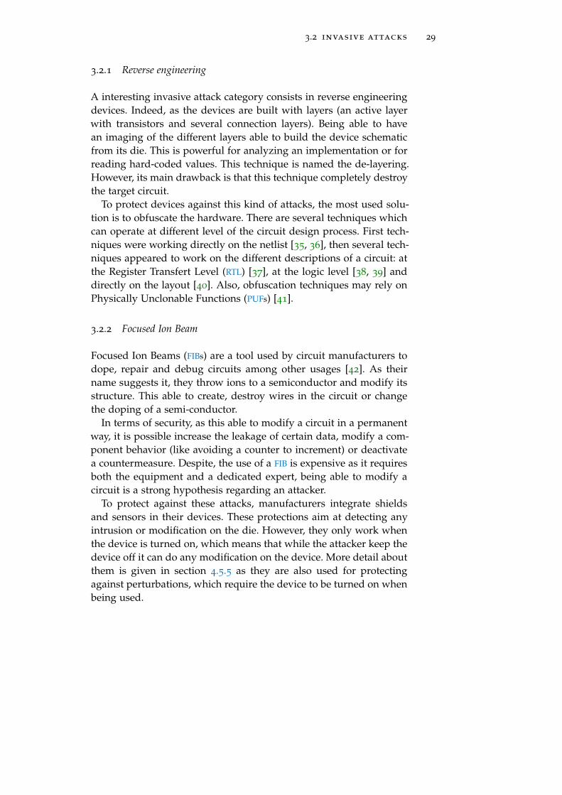
3.2 invasive attacks 29
3.2.1 Reverse engineering
A interesting invasive attack category consists in reverse engineeringdevices. Indeed, as the devices are built with layers (an active layerwith transistors and several connection layers). Being able to havean imaging of the different layers able to build the device schematicfrom its die. This is powerful for analyzing an implementation or forreading hard-coded values. This technique is named the de-layering.However, its main drawback is that this technique completely destroythe target circuit.
To protect devices against this kind of attacks, the most used solu-tion is to obfuscate the hardware. There are several techniques whichcan operate at different level of the circuit design process. First tech-niques were working directly on the netlist [35, 36], then several tech-niques appeared to work on the different descriptions of a circuit: atthe Register Transfert Level (RTL) [37], at the logic level [38, 39] anddirectly on the layout [40]. Also, obfuscation techniques may rely onPhysically Unclonable Functions (PUFs) [41].
3.2.2 Focused Ion Beam
Focused Ion Beams (FIBs) are a tool used by circuit manufacturers todope, repair and debug circuits among other usages [42]. As theirname suggests it, they throw ions to a semiconductor and modify itsstructure. This able to create, destroy wires in the circuit or changethe doping of a semi-conductor.
In terms of security, as this able to modify a circuit in a permanentway, it is possible increase the leakage of certain data, modify a com-ponent behavior (like avoiding a counter to increment) or deactivatea countermeasure. Despite, the use of a FIB is expensive as it requiresboth the equipment and a dedicated expert, being able to modify acircuit is a strong hypothesis regarding an attacker.
To protect against these attacks, manufacturers integrate shieldsand sensors in their devices. These protections aim at detecting anyintrusion or modification on the die. However, they only work whenthe device is turned on, which means that while the attacker keep thedevice off it can do any modification on the device. More detail aboutthem is given in section 4.5.5 as they are also used for protectingagainst perturbations, which require the device to be turned on whenbeing used.


4P E RT U R B AT I O N AT TA C K S
Laziness is the mother of all bad habits.But ultimately she is a mother and we should respect her.
— Nara Shikamaru (Naruto)
abstract
This chapter shows an overview of perturbation attacks. From theirgenesis, it describe a large overview of research topics related to thisproblematic: the injection mediums, the fault models, the fault analy-sis, some famous attacks using faults and the countermeasures.
Contents
4.1 Genesis 33
4.2 Inducing a fault: injection mediums 34
4.2.1 Design considerations 34
4.2.2 Clock glitches 36
4.2.3 Voltage glitches 36
4.2.4 Temperature manipulation 37
4.2.5 Electromagnetic perturbations 37
4.2.6 Optical perturbations 39
4.2.7 Body biasing 41
4.2.8 X-Rays 41
4.2.9 Software induced perturbations 41
4.3 Characterizing a fault 44
4.3.1 Fault models 44
4.3.2 Fault analysis 46
4.4 Exploiting a fault 47
4.4.1 Fault attacks against multi-application sys-tems 47
4.5 Countermeasures 56
4.5.1 Space redundancy 57
4.5.2 Operation duplication 57
4.5.3 Infection countermeasure 58
4.5.4 Code hardening 58
4.5.5 Sensors 60
4.6 Conclusion on perturbation attacks 60
31

32 perturbation attacks
Perturbation attacks intend to stress a target device by pushing itbeyond its nominal execution point to force unintended behavior. Insome cases, such behavior can create security breaches in the system.Usually, knowing that a perturbation able to break a security featureis enough for most attacks. However, having a model of the possi-ble perturbations, understand their impact on the hardware and onthe software, etc, is important to build efficient countermeasures andevaluate the impact of such attacks.
For these reasons, perturbation attacks became an important re-search field in hardware security and their analysis and evaluationon devices is a time consuming and complex process summarized infigure 16.
characterization
device
injectionmedium
faultmodel
analysis
implementation
attackpath
exploitation
countermeasure
Figure 16: Perturbation attack analysis and evaluation process
This figure presents the analysis and evaluation process for a sys-tem against Fault Attacks (FAs). The aim is to build a system com-posed of a device and implementations resistant to FAs. To assess thisresistance several steps are needed.
The first step is the fault characterization, it consists in determiningin which ways the device is perturbed regarding different injectionmediums. These mediums are the different techniques that can beused to induce a fault in the device and are presented in section 4.2.The result of this characterization is the fault model which is a repre-sentation of the fault effects on the device. There are numerous faultmodels and being able to determine it may be a complex process, thisis presented in section 4.3.1.
The next step is the implementation analysis regarding the faultmodel. This consists in simulating or emulating the possible faultmodels determined on the device on an implementation as presentedin section 4.3.2. As many fault models can be considered and regard-ing the complexity of the implementation, testing every fault at anystage of the implementation is too time consuming, making this stepvery tricky, in particular on complex implementations. The result isan attack path which can be exploited for confirming its relevance.The exploitation allows to evaluate the difficulty of doing the attackand to measure its impact. Some of them are presented in section 4.4with a presentation of a system security model.

4.1 genesis 33
The last step is building efficient countermeasures. Regarding theinjection medium, the fault model or the implementation differentcountermeasures can be adopted and integrated to the device orthe implementation. Some FA countermeasures are presented in sec-tion 4.5. Once a countermeasure is designed and integrated in thesystem, a new characterization and/or analysis can be done to evalu-ate its efficiency. This loop can be repeated as many times as neededto reach the desired security level.
This chapter will present an overview of the public work aboutperturbation attacks. It aims at providing a clear and large overviewof the challenges the securing of systems highlight and how they aresettled by the community.
4.1 genesis
Despite bugs were known to appear in digital devices, the first publicobservation of a perturbed device was due to an unintentional per-turbation on a satellite in 1975 [43]. In this case, memory errors wereobserved due to “galactic cosmic rays”.
From this observation and in order to prevent perturbations on in-production satellites, a lot of characterization work on circuit has beendone to characterize and prevent the effects of cosmic rays in MetalOxide Semiconductor (MOS) memory cells [44], Very Large Scale Inte-gration (VLSI) circuits [45] and Dynamic RAMs (DRAMs) [46].
The functional analysis of digital devices kept going by studyingthe impact of different perturbations. The effects of high tempera-ture [47], alpha-particules [48], heavy ions [49, 50] and lasers [51, 52]were analyzed to simulate the space environment on semiconductordevices.
In parallel of device safety, cryptographic researcher teams, awareof the presence of faults in devices, were working on cryptanalysingalgorithms in the presence of faults. The seminal work was publishedin a memo about the RSA signature generation [53].
Later on, a lot of algorithms were analyzed: the RSA and Rabinsignature [54], secret key algorithms like Data Encryption Standard(DES) [55], public key signature algorithms (RSA, ElGamal, Schnorrand DSA) [56] and Elliptic Curve Cryptography (ECC) [57].
At this point, around 2000’s, the perturbation of devices was doneusing various mediums and cryptographic attacks based on faultswere only theoretical and these two disciplines did not already match,at least publicly.
In the 90’s, the French security agency, the Service Central de la Sécu-rité des Systèmes d’Information (SCSSI) and the French national telecom-munication center, the Centre National d’Étude des Télécommunications(CNET) were already evaluating secure devices against FAs, mostly us-ing light and lasers.
The first public work was published in 2002 with Skorobogatov [58].In his work, he presents the usage of a laser, usually used to simulate

34 perturbation attacks
cosmic ray, to intentionally perturb a Micro-Controller Unit (MCU). In2005, in his thesis, he introduces the semi-invasive attacks [59].
From this moment, research on FA was focused on several points:the analysis of various injection mediums, the exploitation of faults,the simulation of faults in circuits and programs and the building ofcountermeasures.
4.2 inducing a fault : injection mediums
Perturbation attacks rely on the apparition of faults during a sys-tem execution. During an attack, these faults are intentionally createdwithin the device. To behave correctly, digital devices have to fulfillphysical constraints. These constraints are directly linked to their de-sign and, if they are respected in their nominal operation point, it ispossible to break these constraints conditions by inducing stimuli inthe device as presented in figure 17.
Clock
Voltage
Temperature
Electromagneticwaves
Light
X-ray
Body biasing
Software
Figure 17: Stimuli able to perturb a digital device
Most of these stimuli are physical like the voltage, the temperature,the EM waves, the light, the X-rays, the clock and the body biasing.They are used to push some components of a device at their limit ofoperation, inducing faults in them.
While perturbing a device, three behaviors can create a fault, atiming violation [60], a sampling error [61] or a transient current [62].This section presents the design of a synchronous circuit and howthese injection mediums actually induce faults in them.
4.2.1 Design considerations
Before understanding how faults are induced into a device, it is im-portant to understand how they are designed and how this design isconstrained.
Timing faults comes from the instability of DFFs, also known asregisters. Indeed, in synchronous circuits, registers sample the outputdata of the logic synchronized with the chip frequency. But to sample
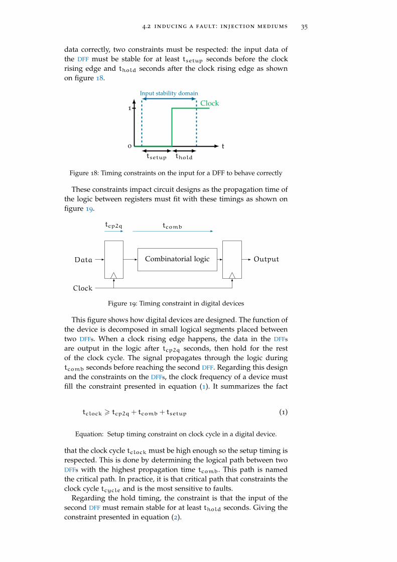
4.2 inducing a fault : injection mediums 35
data correctly, two constraints must be respected: the input data ofthe DFF must be stable for at least tsetup seconds before the clockrising edge and thold seconds after the clock rising edge as shownon figure 18.
0
1
Input stability domain
tsetup thold
Clock
t
Figure 18: Timing constraints on the input for a DFF to behave correctly
These constraints impact circuit designs as the propagation time ofthe logic between registers must fit with these timings as shown onfigure 19.
Data
Clock
Combinatorial logic Output
tcp2q tcomb
Figure 19: Timing constraint in digital devices
This figure shows how digital devices are designed. The function ofthe device is decomposed in small logical segments placed betweentwo DFFs. When a clock rising edge happens, the data in the DFFs
are output in the logic after tcp2q seconds, then hold for the restof the clock cycle. The signal propagates through the logic duringtcomb seconds before reaching the second DFF. Regarding this designand the constraints on the DFFs, the clock frequency of a device mustfill the constraint presented in equation (1). It summarizes the fact
tclock > tcp2q + tcomb + tsetup (1)
Equation: Setup timing constraint on clock cycle in a digital device.
that the clock cycle tclock must be high enough so the setup timing isrespected. This is done by determining the logical path between twoDFFs with the highest propagation time tcomb. This path is namedthe critical path. In practice, it is that critical path that constraints theclock cycle tcycle and is the most sensitive to faults.
Regarding the hold timing, the constraint is that the input of thesecond DFF must remain stable for at least thold seconds. Giving theconstraint presented in equation (2).

36 perturbation attacks
tcp2q + tcomb > thold (2)
Equation: Hold timing constraint on clock cycle in a digital device.
This equation summarizes that the propagation in the logical can-not be too fast otherwise the hold timing will not be respected.
The non-respect of the setup or hold constraints is a well knownsource of bugs, in particular due to variations in the manufacturingprocess of devices which can modify the critical path [63].
4.2.2 Clock glitches
Clock glitches are local variation of the target device clock frequency.They aim at breaking the constraint presented in equation (1) andtherefore introduce a fault in DFFs. This behavior is presented in fig-ure 20.
Clock
InputV1 V2 V3 V4
OutputV1 V2 V3 V4
(a) Normal behavior of a DFF
Clock
InputV1 V2 V3 V4
OutputV1 V2 V4
Glitch
Faulted value
(b) Overclocking effect on a DFF
Figure 20: Clock glitch effect on a DFF
This figure shows how a setup timing violation can be done usinga clock glitch. Due to this glitch, the value V3 is not held long enoughto ensure that the value is correctly sampled by the DFF.
This injection medium was used to attack smartcards [64] as theyare powered by an external clock. It was also recently used in a specialkind of perturbation attack named ClkScrew [65] in which the SoC
corrupted PMIC intentionally modifies the cores frequency on the fly.
4.2.3 Voltage glitches
Voltage glitches intent to create timing errors by modifying the propa-gation time in the circuit logic. Indeed, regarding equations (1) and (2)increasing or reducing the logic propagation time tcomb can induceeither a setup timing violation or a hold timing violation. Overpow-

4.2 inducing a fault : injection mediums 37
ering reduces the propagation time and underpowering increases thepropagation time in standard cells [66].
This medium is used for attacking devices with external powersupply such as smartcards [67] or IoT devices [68].
4.2.4 Temperature manipulation
Overheating works in a similar way as voltage perturbation, it createstimings errors by modifying the propagation time of the logic. How-ever, compared with voltage glitches it presents many drawbacks.Due to thermal inertia, realizing a “temperature glitch” is too longcompared with devices computation speed. Also, depending on theprocess technology, overheating may increase or reduce the propaga-tion time in standard cells [66].
Despite these drawbacks, heating faults were successfully used toattack a RSA implementation on a micro-controller [69].
4.2.5 Electromagnetic perturbations
EM perturbations create sampling errors in the chip DFFs [70]. Sam-pling errors appears when an EM perturbation modifies the behaviorof a DFF when its commuting. In other word, EM perturbations createerrors in DFF outputs on clock rising edges.
The sampling faults come from a bad sampling of the DFF input (D)during an EM perturbation [71]. The phenomenon which leads to thesampling fault is summarized in figure 21.
This figure presents how the signals of a DFF behave against anEM perturbation. These signals are the supply voltage (S), the clock(Clk), the input (D) and the output (Q). Figure 21a shows the injectedEM Pulse (EMP) (Pem) and the corresponding induced current (Iind)which will appear in the chip. On the EMP rising edge, this currentwill induce a supply voltage drop as depicted in figure 21b.
38 perturbation attacks
0
Vdd
Vdd
2
Iind
Pem
t
I H
(a) Electromagnetic pulse and induced current (absolute units)
0
Vdd
Vdd
2
tv2
S
t
V
(b) Supply voltage drop and restoration due to electromagnetic pulse
0
Vdd
Vdd
2
tv2 trise
D
Clkexpt
V
(c) DFF input (D) drop and restoration due to electromagnetic pulse and nonglitched clock
0
Vdd
Vdd
2
tv2 trise
Q
Clkt
V
(d) DFF output (Q) drop and restoration due to electromagnetic pulse and glitchedclock
Figure 21: How EM sampling faults occur [71]

4.2 inducing a fault : injection mediums 39
On the falling edge, a reverse current will appear which will restorethe supply voltage level. The important thing to note in figure 21b isthat since the supply voltage level is below Vdd/2 the chip is stalledas all transistor are de facto blocked.
A consequence of this stalling is that all signals (D, Clk and Q)are stuck to 0 as represented in figures 21c and 21d. Once the supplyvoltage cross Vdd/2 (at tv2 s), all the signals are restoring. It is duringthis restoring phase that the sampling fault can appear.
The figure 21c shows the non glitched clock Clkexp with the glitchedDFF input. The sampling error happens when the clock signal arisesbefore the input value D has reached Vdd/2 as in this case a logical 0will be sampled instead of a logical 1.
The figure 21d presents a case where the clock signal restoredquickly and the rising edge happen while the input value is still be-low Vdd/2 (at trise s). In this case, the sampled value is a logical 0 andthe output Q is therefore constrained to 0V instead of Vdd causingthe error.
This behavior shows that EM perturbations must be well synchro-nized with the clock rising edges to produce faults. Also, this demon-strates that EM perturbations can be used to force bits from 1 to 0
quite easily. Despite these constraints, EM perturbations is a very usedinjection medium, mainly for its ease of use as most of the time notarget preparation is needed and it has a good accuracy [72]. Finally,EM perturbation successes attacking various systems as MCU cachememories [73] and modern processor secure boot [74] for instance.
4.2.6 Optical perturbations
Optical perturbations are used to induce currents in a chip. Indeed, astransistors are basically a silicon crystal, they have optical propertiesand are sensitive to light. This property was very useful back whenthe only memories available were EPROMs. These particular memo-ries can store data which can be erased using Ultra Violet (UV) light(figure 22). The CMOS transistor optical properties are still used forcamera photo-diodes [75] which are basically transistors without agate.
Figure 22: ST Microelectronics M27C256B EPROM

40 perturbation attacks
Also, as mentioned in section 4.1, Infra Red (IR) lasers are used tosimulate cosmic rays effects on CMOS transistors. Both UV [76] andIR [77] are used in hardware security.
Optical perturbations induce currents in CMOS logical gates whichcan lead to bit flips as presented on a CMOS inverter in figure 23.
Vdd out = 0 (1) gnd
in = 1
i
RT
Laser pulse
e−
i 6= 0→ Vout = RT · i
Figure 23: Laser effect on a CMOS logical inverter outputting a logical zero
This figure shows the effect of a laser pulse on CMOS logical inverterwhich outputs a logical 0. Considering the gate is in its stationarystate, as the input is a logical 1, the P-doping MOS (PMOS) transistor(on the left) is blocked and the N-doping MOS (NMOS) transistor (onthe right) is passing and equivalent to a resistor RT . In this situation,the out signal is connected to the ground and there is no current i inRT . A fault can be obtained by illuminating the transistor drain witha laser pulse. The photons coming from the laser will disperse theirenergy in the crystal and create electrons. Because it is their onlyway, these electrons will migrate to the ground, this migration willresult in a current i through the resistance RT and therefore a voltageVout = RT · i between the output of the gate and the ground willappear. If enough electrons are produced, this voltage will exceedVdd/2 and the gate output will therefore correspond to a logical 1
which is the wrong value.This remains available if the gate outputs a logical 1, in this case,
the PMOS is passing and the NMOS is blocked. Therefore electrons willmigrate to the supply voltage and this will create a voltage whichoppose Vdd and forces the output to a logical 0.
As this can be applied to any CMOS gates with more or less difficul-ties, optical fault attacks able to flip bits in devices. Attacks relyingon these faults are called optical fault masking [78] because bit flipscan be modeled using a logical mask XORed with the target value aspresented in equation (3).
v = v⊕ e (3)
Equation: Fault masking attack model.

4.2 inducing a fault : injection mediums 41
This equation models bit flips using a logical mask e also called theerror, which is XORed to a target value v to obtain a faulted value v.The applied mask is usually bit-wide or byte-wide.
In addition to their modeling, Laser Fault Injections (LFIs) also presentthe best repeatability and accuracy among fault injection mediums.For these reasons, it is one of the most used medium, in particu-lar in high-level certification processes. It was used to successfullyattack memories [77], cryptographic implementations [79], PUFs [80]and smartphone secure-boot [81].However, considering modern SoCs,the transistor technology is usually around 10nm while the size ofa laser spot is usually 1µm which means that contrary to what isdepicted on figure 23, we usually target a many transistors.
4.2.7 Body biasing
Body biasing is a technique which consists in biasing the substrate oftransistors in a circuit. This technique is usually used in low powerdevices to modulate the transistor threshold [82]. The bias is usuallyaround a few mV .
In hardware security, Forward Body Biasing Injection (FBBI) consistsin glitching the transistor substrate with an important voltage (60Vduring 8µs [83]). This glitch provokes a threshold modification intransistors blocking them all, introducing faults in the circuit [84].
4.2.8 X-Rays
X-rays are the youngest injection medium used in hardware secu-rity [85]. However, as mentioned in section 4.1, cosmic rays (and inparticular X-rays) are known to perturb digital devices for a longtime.
X-rays can empty the charges of floating gates of transistors andtherefore force zeros in flash memories or Electrically EPROM (EEPROM).They also can modify the behavior of transistors, forcing NMOS aspassing and PMOS as blocked. This able circuit edition but the phe-nomenon is reversible by heating the circuit to 150 °C during 1h. Asthey can be focused to a nano-scale (and therefore target a singletransistor), X-rays are the most accurate injection medium but a syn-chrotron is required for such accuracy [85].
4.2.9 Software induced perturbations
Recently, some software induced perturbations have been presented.These perturbations rely either on a software overusing a componentlike in the rowhammer attack (section 4.2.9.1) or on a corrupted en-ergy manager like in the ClkScrew attack (section 4.2.9.2).

42 perturbation attacks
4.2.9.1 Rowhammer attacks
Rowhammer attacks are a special kind of perturbation attacks be-cause they are triggered via software. They rely on the rowhammerbug to force bit-flips in the memory of a digital device [86]. Therowhammer bug is based on a natural phenomenon, the discharg-ing of capacitor over the time. In DRAMs, data is stored in the form ofcharges in capacitor as shown in figure 24.
Capacitor storing the charge
Access transistor
Figure 24: One-bit DRAM memory cell
These capacitors naturally discharge over time and to not lose in-formation, DRAMs have a refresh mechanism to recharge them. Usu-ally, this refresh happens every 64ms. Rowhammer attacks consistsin accelerating the discharge of capacitors in DRAMs so they are fullydischarged when the refresh happen. As the presence of a charge caneither be considered as a logical 1 (in the case of true-cells) or as alogical 0 (in the case of anti-cells), this mechanism can be used to flipbits in the memory.
Accelerating the discharge of a memory cell is done by keepingactivated the memory lines around it. Indeed, DRAMs are organizedas a matrix, when a data is read, the line storing it is activated andcopied in the memory row buffer and the needed data is read fromthis buffer as presented in figure 25.
Activating a line accelerate the discharging of its adjacent lines ca-pacitors. By remaining a line activated it is therefore possible to dis-charge the capacitors of its adjacent lines faster than the refresh pe-riod. Usually the rowhammer attack is realized by activating the twolines surrounding the targeted one. A line is kept activated by contin-uously reading a data in it (500 000 accesses in less than 64ms). Thishigh repetition of reads at a specific line in the DRAM have given thename rowhammer to the attack.
Rowhammer attacks were used to successfully attack various sys-tems with different OS and architectures. The first one was presentedby the Google team Project Zero in which they achieved a privi-lege escalation under Linux on an Intel processor [87]. Latter on,various rowhammer attacks were published: a remote attack usingJavaScript [88], an attack on an ARM device powered by Android [89],one using the integrated GPU of a SoC to fast access the DRAM [90]and one using TCP/IP and the Remote DMA (RDMA) to hammer theDRAM from the network [91].

4.2 inducing a fault : injection mediums 43
Row buffer
Line activation
Copy
Column activation
Memory output
Figure 25: DRAM line activation and copy in the row buffer
The last attack using rowhammer is a side-channel attack. Indeed,the more capacitors in the target line are charged, the more probablea bit-flip will happen using rowhammer. This probability variationleaks information about the content of the target line which is there-fore used as a side-channel for reading a memory using rowhammerin the RAMbleed attack [10].
4.2.9.2 ClkScrew attacks
The ClkScrew attack targets highly integrated SoCs. For optimizingtheir performance on consumption ratio, these SoCs integrate a PowerManagement Subsystem (PMS). This PMS supply the power voltageand the clock to every other modules as presented in figure 26.
CoresPMS
Othermodules
V
Clk
Drive
Figure 26: PMS supplying the power voltage and clock to cores and moduleof a SoC

44 perturbation attacks
The PMS is composed of a PMIC and Phase Locked Loops (PLLs)which supply the SoC modules with power voltage and a clock and isdriven by the cores in kernel mode.
On modern devices, such as smartphones, the cores have variouswork domains which correspond to different power voltage and clockfrequency pairs. The idea of the ClkScrew attack is to force a coredoing a sensitive operation in an unstable domain (voltage/frequencycouple) which will provoke timing errors and, therefore, faults.
There are two attacks using this path: the ClkScrew attack targetingthe ARM TrustZone TEE of a Nexus 6 smartphone to load non-trustedapplications in it [65] and the PluderVolt attack targeting the Intelsecure enclave (SGX) [92]. As these attacks are recent, many questionsremains about the security of integrated modules and how to isolatethem from this kind of attacks.
4.3 characterizing a fault
Being able to induce a fault in a working device is not enough torealize an attack. As all faults are not exploitable, obtaining an ex-ploitable fault and actually exploiting it may be a trickier businessthan injecting a fault in a working device.
To simplify their exploitation, faults are characterized on the target,this characterization is a very time consuming process as many pa-rameters are involved (the location of the perturbation, the intensity,the timing, etc). The characterization gives a fault model, this faultmodel is the set of the possible faults associated to their probabilityof occurrence [93]. The fault model is then used to analyze the tar-get security mechanisms. In some cases, the fault can be exploited toattack the mechanism.
4.3.1 Fault models
Determining the fault models is very important for measuring theimpact of a fault and build efficient protections against it. However,as digital devices have a complex architecture with many abstractionlayers, the impact of a fault may be interpreted differently dependingon the considered layer as shown on the figure 27.
This figure shows how a fault can propagate through the differentabstraction layers of a device. In section 4.2, we have seen how per-turbations can be created inside transistors and standard cells. Thiscorrespond to the logical level. However, in some cases, it is not pos-sible to have information about the deep behavior of the target andtherefore a more abstracted fault model is determined. Furthermore,anticipating the fault effect at a specific layer from the underlyinglayer is not straightforward due to the scaling factor between them.
For these reasons, some works have focused on determining whatfaults can be achieved regarding the different abstraction layers, withdifferent injections medium on various targets. A summary of theseworks is presented in figure 28.

4.3 characterizing a fault 45
Softwarecharacterization
Hardwarecharacterization
ISA
Micro-architecture
Logic
Program
Fault
Data/Instructioncorruption
Bad fetchRegister corruption
Signal perturbation
Control flow hijacking
Figure 27: Fault propagation through digital devices abstraction layers withsome fault effects as examples. Inspired from [94].
This figure presents the different observed fault models in variousconditions. The logical level was discussed in section 4.2 and is there-fore not represented. Three types of target are considered here, theMCU CPUs, the Field Programmable Gate Arrays (FPGAs) and the mod-ern CPUs. MCUs are the most studied as they are widely used in secureand IoT devices, FPGAs are rarely used and focus on deep characteri-zation. Modern CPUs are quite new and more complex, therefore theyare less studied than MCUs CPUs.
At the micro-architectural level, several components were observedto be sensitive to faults. In [73], the authors observed that an EM
perturbation can corrupt the cache fetching to replay instructions byskipping others. In general, memory elements are sensitive to per-turbation, especially the flash memory which was successfully cor-rupted using both EMPs [103, 104] and LFIs [105, 106] on various tar-gets. These attacks were able to corrupt both executed code and data.Another way to fault data is to target the data bus as demonstratedin [102] using EMP. Clock and voltage glitches are mainly perturbingthe pipeline [67] as it is mostly where the critical paths are, this wasdeeply studied in a LEON-3 implemented on a FPGA in [108].
Regarding the ISA level, the main targets are either the instructionsor the data [67]. Both effects can be obtained using various injectionmediums on all types of targets, including modern CPUs [101, 107].Faults on data are quite easy to analyze as the masking fault modelpresented in section 4.2.6, which consists in XORing the data witha mask, is usually used. Regarding instructions, there are multipleways to analyze the fault. The masking fault model can be used byconsidering the instruction as a data [104]. Sometimes, it is possible tobe more precise by considering the type of instruction. On a data pro-

46 perturbation attacks
Injection mediums
Ab
stra
ctio
nla
yer
Targets:
Micro-architecture
ISA
Program
Clock Voltage EM Laser
Instruction skipand corruption onATMega163 [95]
Forced memoryACK onMCUs [68]
Control flowhijacking on ARMCortex-M3 [96]
Fault AES onARM Cortex-A9 [97]
Data corruption onARM Cortex-M3 [98]
Instruction skip onATMega328P [99]
Data and instructioncorruption on MCUs [67]
Instruction skip anddata corruptionon ATMega328P [100]
Instructioncorruption onARMCortex A [101]
Cache corruption onARM Cortex-M4 [73]
Data bus corruption [102]on ARM Cortex-M3
Flash corruptionon MCUs [103, 104]
Flash corruption onATMega328P [105] andARM Cortex-M3 [106]
Instruction corruptionon ARM Cortex-A9 [107]
Pipelinecorruption onRISC-VLEON-3 [108]
MCU’s CPU modern CPU FPGA
Figure 28: Fault injection characterization state of the art.
cessing instruction faults usually affect the operands [107] while on abranch instruction, it is the address that is usually corrupted [100].
Finally, program level characterization works are usually prelimi-nary works which are used as a proof of concept. For instance, in [68],the authors present a voltage glitch method which consists in shapingthe voltage glitch using a genetic algorithm [109]. The work presentedin [107] is the first to focus on modern CPUs by targeting an A seriesARM core and [96] focus on software vulnerabilities in IoT devices,such as a fault triggered backdoor for instance.
4.3.2 Fault analysis
The fault analysis is an important step as it able to identify attackpaths regarding a program and fault models, to measure the impactof potential attacks and to build adapted countermeasures.
As they rely on fault models, fault analysis can also be separatedin categories depending on the abstraction level we are working on.Fault analysis can be compared to a code review which integrate thepossibility to have runtime faults. There are two strategies: a staticanalysis or a dynamic analysis. As faults are used to perturb a targetduring its execution, most works about analyzing implementationsagainst faults use the dynamic approach.
As the fault models can be numerous and happen at anytime dur-ing the target execution, the number of cases to test is absolutely gi-gantic. To answer this issue, many works propose tools to automatizethe analysis by simulating the perturbation of implementations.

4.4 exploiting a fault 47
At the logical level, PAFI [110] simulates Verilog code to analyzethe susceptibility of a design against faults. In the fault analysis lit-erature, the micro-architectural layer is named system level. Severaltechnologies are used to build analysis at this level like SystemC [111]or QEMU [112].
Several works for fault analysis at the ISA level has been done. Themain reason is that as many assembly languages exist with their ownspecificities, building an efficient generic analysis tool is complicated.Also, several methods were proposed to improve the efficiency ofthe analysis. In [113], the authors focus on the JavaCard bytecodewhile [114] proposes a formal verification of countermeasures usinga SMT-solver.
Finally, in order to realize more generic fault analysis, several workshave focus on doing the analysis at the program level, i.e. on thesource code [115] or the Control Flow Graph (CFG) [116, 117] of theprogram.
4.4 exploiting a fault
The exploitation of faults is a complicated task. Even if the faultmodel and the fault analysis helps in being confident of the suc-cess of an exploitation, some un-modeled constraints may harden theexploitation. This section presents the general approach of famousattacks and proposes a classification based on the system securitymodel introduced in figure 14 in section 2.4.
4.4.1 Fault attacks against multi-application systems
A multi-application system can be attacked in many ways, however,in hardware and embedded systems security, a system is consideredbroken if a security property or a security mechanism presented infigure 14 cannot be trusted.
Regarding FAs, the perturbation will affect either the data integrityor the execution flow then propagate itself. Depending of the case, dif-ferent security mechanisms or properties can be broken. The follow-ing section presents the most famous attacks regarding these mecha-nisms and properties.
4.4.1.1 Fault attacks targeting cryptography
Cryptography is historically the most attacked mechanism. Indeed,the first security concerns were about the resilience of these algo-rithms, therefore a lot of work has been driven to evaluate the im-pact of fault attacks on cryptographic algorithms implemented in SEs.This section presents some famous exploits on implemented cryptog-raphy.
rsa-crt modulus factorization (bellcore attack)
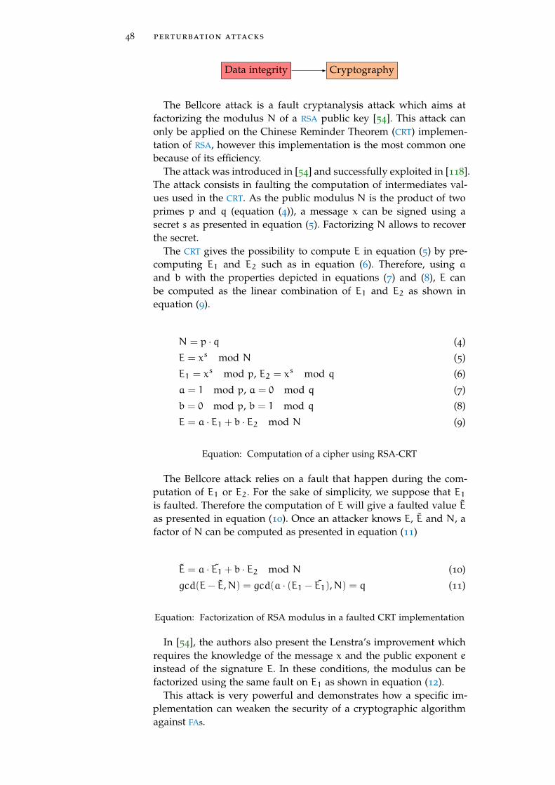
48 perturbation attacks
Data integrity Cryptography
The Bellcore attack is a fault cryptanalysis attack which aims atfactorizing the modulus N of a RSA public key [54]. This attack canonly be applied on the Chinese Reminder Theorem (CRT) implemen-tation of RSA, however this implementation is the most common onebecause of its efficiency.
The attack was introduced in [54] and successfully exploited in [118].The attack consists in faulting the computation of intermediates val-ues used in the CRT. As the public modulus N is the product of twoprimes p and q (equation (4)), a message x can be signed using asecret s as presented in equation (5). Factorizing N allows to recoverthe secret.
The CRT gives the possibility to compute E in equation (5) by pre-computing E1 and E2 such as in equation (6). Therefore, using a
and b with the properties depicted in equations (7) and (8), E canbe computed as the linear combination of E1 and E2 as shown inequation (9).
N = p · q (4)
E = xs mod N (5)
E1 = xs mod p, E2 = xs mod q (6)
a = 1 mod p, a = 0 mod q (7)
b = 0 mod p, b = 1 mod q (8)
E = a · E1 + b · E2 mod N (9)
Equation: Computation of a cipher using RSA-CRT
The Bellcore attack relies on a fault that happen during the com-putation of E1 or E2. For the sake of simplicity, we suppose that E1
is faulted. Therefore the computation of E will give a faulted value E
as presented in equation (10). Once an attacker knows E, E and N, afactor of N can be computed as presented in equation (11)
E = a · E1 + b · E2 mod N (10)
gcd(E− E,N) = gcd(a · (E1 − E1),N) = q (11)
Equation: Factorization of RSA modulus in a faulted CRT implementation
In [54], the authors also present the Lenstra’s improvement whichrequires the knowledge of the message x and the public exponent einstead of the signature E. In these conditions, the modulus can befactorized using the same fault on E1 as shown in equation (12).
This attack is very powerful and demonstrates how a specific im-plementation can weaken the security of a cryptographic algorithmagainst FAs.

4.4 exploiting a fault 49
gcd(x− Ee,N) = q (12)
Equation: Factorization of RSA modulus in a faulted CRT implementation(Lenstra’s improvement)
attacking logarithm exponentiation square and multi-ply implementations
Execution flow Cryptography
The square and multiply algorithm is the most used algorithm forcomputing the logarithm exponentiation. This algorithm iterates overall the bits of the private exponent s = st−1, ..., s0, squares the inter-nal state R and if the current bit is set to 1, it multiplies the messageas presented in algorithm 1. In the case of a signature, this allows tocompute E = xs mod N.
Algorithm 1: Left to right square and multiply algorithm forlogarithm exponentiationResult: E = xs mod N
1 R = 1;2 for (i == t− 1; i > 0; i−−) do
3 R← R · R mod N;4 if si == 1 then
5 R← R ·m mod N;6 end
7 end
Fault attacks on this algorithm rely on the corruption of the squar-ing operation (line 3). [54] introduces an attack which is based on acorruption of the squaring while [119] presents and successfully re-alizes an attack based on the skipping of one squaring during thesignature. I present the attack using the skipping fault model.
Skipping the last squaring gives a faulty signature x0, this signa-ture’s difference with the real one x depends on the value of the firstbit of the secret exponent s0 as shown in equation (13).
x =
(x0)2 if s0 = 0
(x0)2 ·m if s0 = 1
(13)
Equation: Relation between the faulty signature obtained by skipping thelast squaring and the correct signature in the square and multiply algorithm.
Once a bit has been recover, it is possible to recover the next bitby comparing the faulty signature xi with xi−1. Indeed, between two

50 perturbation attacks
iterations of the loop line 2, the internal state Ri has only two possiblevalues regarding the previous state as shown in equation (14).
Skipping the squaring in the ith loop iteration simplifies this rela-tion as depicted in equation (15). Finally, after the whole signaturecomputation, the faulty signature xi obtained by skipping the ith
round squaring is directly linked to the previously observed faultysignature (i.e., the one observed by skipping the (i− 1)th round squar-ing) as presented in equation (16).
This attack allows to recover the complete private exponent by in-jecting a fault for every bit to recover.
Ri =
(Ri−1)2 if si = 0
(Ri−1)2 ·m if si = 1
(14)
Ri =
Ri−1 if si = 0
Ri−1 ·m if si = 1(15)
xi =
xi−1 if si = 0
xi−1 ·m2i−1
if si = 1(16)
Equation: Relation between the faulty signature obtained by skipping thesquaring in the ith and (i − 1)th iteration of the loop in the square andmultiply algorithm.
rsa modulus corruption
Data integrity Cryptography
In the RSA algorithm, the integrity of the modulus N is very sen-sitive. Indeed, because the private key is based on its number of co-prime Φ(N), any attacker able to compute this value can forge, usingthe extended euclidean algorithm for instance, a legitimate privatekey d corresponding to a known public key e as depicted in equa-tion (17).
e · d = 1 mod Φ(N) (17)
Equation: Bézout’s identity
Corrupting the modulus N can simplify the computation of Φ(N).The aim is either to force the modulus to be a prime, in this caseΦ(N) = N− 1 or to make it easily factorizable, simplifying the com-putation of Φ(N).

4.4 exploiting a fault 51
This technique was successfully used in the ClkScrew attack [65]for loading an un-trusted application in the TEE of a smartphone.
persistent fault analysis on aes
Data integrity Cryptography
The Persistent Fault Analysis (PFA) relies on the corruption of SubstitutionBoxes (SBoxes) in a persistent way. This means that the fault remainsactive until the target is reset. This able to realize several operationswith the same faulted value.
This kind of fault was first used to attack the AES algorithm in [120]and a practical attack using UV light to corrupt AES SBoxes lookuptables was presented in [76].
Corrupting SBoxes implies that they are biased. The consequence isthat for an entry x the output is y = SB(x) instead of y = SB(x),moreover, as the SB is initially a bijection, no other input value canoutput the y value in the faulted SBox SB.
Considering the last round of AES, the ith byte of the cipher Ci iscomputed with the secret key K and the previous round internal stateith byte Xi as presented in equation (18).
Ci = SB(Xi)⊕Ki (18)
Equation: AES last round SubBytes and AddRoundKey operations in the pres-ence of a corrupted SBox
Actually, because the SBox is faulted the internal state X is also afaulted value but it doesn’t matter in the attack. The important thingis that there is a value for Ci which is unreachable because of the SBox
corruption. This value is the y introduced above. This unreachablevalue (named forbidden value in the literature) is easily identifiableby observing the output ciphers. We name this value C∗
i for the ith
byte of the cipher and it is directly linked to the ith byte of the keyas shown in equation (19).
C∗i = y⊕Ki (19)
∀i,Ki = y⊕C∗i (20)
Equation: Relation between the forbidden value and the secret key
At this point, y has only 28 possible values. By guessing the y
value it is possible to directly recover all the key bytes as shown inequation (20). This reduces the number of possible keys to 28 val-ues and the verification can be done by knowing a plaintext and itscorresponding cipher.

52 perturbation attacks
differential fault analysis (dfa)
Data integrity Cryptography
The DFA is a cryptanalysis technique which relies on the compari-son of the correct cipher and a faulty cipher of the same (unknown)plaintext. In [55], the authors presents the attack for the DES algo-rithm. [121] introduces a DFA technique usable for the AES which wasextended in [122] and [57] presents a DFA for ECC.
The DFA on AES is the most famous attack among all DFAs and wassuccessfully exploited in [123] and even on a DFA protected AES bysimultaneously injecting two faults in the implementation [124]. Theprinciple of the attack is to realize a fault on a byte of the AES statebefore the last MixColumns operation, in the 9th round as presented infigure 29.
SR MC ⊕ SB SR ⊕ c (c’)
k9 k10
fault ∆
Figure 29: DFA Principle
Once the faulty ciphertext c’ is obtained, the attacker can computethe value ∆ such as presented in equation (21).
∆ = SB−1(SR−1(c⊕ k10))⊕ SB−1(SR−1(c ′ ⊕ k10)) (21)
Equation: Relation between the faulty ciphertext, the correct ciphertext andthe possible faulty outputs of the MixColumns operation during a DFA onAES
Faulting one byte of the AES state before the last MixColumns im-plies that the faulted output of the MixColumns (∆) has only 28 pos-sible values. Regarding the equation (21), as the possible values for∆ are known, the only unknown value is k10 and at this point ∆ hasonly four bytes (among sixteen) that are not zeros. The next step con-sists in testing all the values for these four bytes in k10 (232 values intotal) such as the corresponding ∆ is among the possible values.
Given a faulty ciphertext c ′ this computation will give a set of pos-sible values for the k10 bytes. The correct k10 value is the one thatverify the equation (21) for every faulted ciphertexts. In [122], the au-thors demonstrate that the probability to recover the correct key withtwo faulty ciphertexts is around 98%.
Doing a fault on a byte will before the last MixColumns operationleads to a faulty diagonal in the AES as shown in figure 30.
In this figure, the SubBytes and AddRoundKey operations are notrepresented as they do not change the layout of the fault propagation.

4.4 exploiting a fault 53
MixColumns ShiftRows
Faulted byte
Figure 30: Propagation of a faulted byte before the last MixColumns opera-tion in the AES
As one can see, the output has four faulted byte in the pattern of adiagonal. Comparing the correct cipher with the faulty one able toobserve this diagonal and recover the corresponding bytes of the key.
Therefore, doing these steps for the 4 diagonals able to recover the16 bytes of the key with only 8 faulty ciphertexts. Actually, 2 faultyciphertexts can be enough because faulting a byte in the AES stateresult in a faulted diagonal. Therefore, by faulting 4 bytes in the AES
state, it is possible to obtain 4 faulted diagonals with only one cipher.However, these faults are exploitable only if the four initial faultedbytes are on the four different columns of the AES state. Otherwise,there is too many possible values for ∆, reducing the efficiency of theattack.
aes last addroundkey skip
Execution flow Cryptography
The last operation of the AES algorithm is the AddRoundKey. Thisoperation is particularly critical. Indeed, if an attacker is able to skip it,she will obtain a faulty ciphertext c. The difference between this faultyciphertext and the correct ciphertext is simply the XOR operation withthe secret key k as shown in equation (22).
c = c⊕ k (22)
Equation: Relation between the faulty ciphertext and the correct cipher textin the case of the skipping of the last AddRoundKey operation in AES
From this point, the secret key can be trivially recovered by XORingthe faulty ciphertext with the correct one. This attack was successfullyrealized using a laser injection in [79].
4.4.1.2 Fault attacks targeting memory partitioning
Memory partitioning is a basic security feature in multi-applicationsystems. It ensures that, despite the physical memory is shared, an ap-plication cannot access the memory of another application as shownin figure 31.

54 perturbation attacks
Memory
Operating System
App1App2App3
OS 1 2 3
Figure 31: Memory partioning principle
This figure shows how the memory is managed in a multi-applicationsystem. Each application, even the OS itself, has a dedicated subpart ofthe memory. This partitioning is ensured by a dedicated component,the MMU or the MPU, and is configured by the OS at the startup. TheOS can access all the memory as it configures this partitioning, thisimplies that while executing a sensitive application, the OS must betrusted, this trust is ensured by the secure boot. In security, escalatingprivileges can be done by accessing the OS memory and modifyingits configuration.
rowhammer attacks .
Data integrity Memory partitioning
Because of the memory partitioning, creating a malicious applica-tion that will access the OS memory and modify it is not possible.However, using a physical perturbation can induce modifications inthis critical memory. This is a classical attack path in rowhammerattacks [87, 89].
For the example, in Linux-based OS, the memory partitioning ismanaged by a MMU, the MMU gives every application a pool of virtualaddresses they can use to realize memory accesses. When the MMU
receive a memory access, it translates the virtual address (addrvirt)into a physical address (addrphys) using Page Table Entrys (PTEs) asshown in equation (23).
addrphys = PTE+ addrvirt[11 : 0] (23)
Equation: Relation between the virtual address and the physical address inLinux based OS
The PTE is stored in the OS memory. The MMU resolves the PTE’saddress using the upper bits of the virtual address and verifies thatthe application realizing the memory access can access this address.Therefore, an attacker able to corrupt the PTEs can force a memory

4.4 exploiting a fault 55
access to any part of the memory in particular, the OS memory. Thiswas successfully done using rowhammer in [87, 88, 89] to obtainedprivileged rights.
4.4.1.3 Fault attacks targeting secure boot
Data integrity Execution flow Secure boot
As mentioned above, the secure boot is a critical security feature toensure the trust in a OS or an application. The secure boot is the suc-cession of verified stages, each stage is ciphered and signed. The aimof a stage is to verify the authenticity of the next stage, to uncipherit and to execute it . The only exception is the first stage which is defacto trusted and executed at the startup, it is the root of trust.
Bypassing the secure boot able to load an un-trusted OS on the tar-get, this can be critical if a sensitive application is load on such OS,also, if the bypass happens soon enough, critical assets, as the devicemaster key, might still be loaded in the memory. This security wasbypassed on the XBOX360 [125] using a voltage glitch which forcethe return value the signature comparison function to zero. This ex-ploit drove the apparition of modchips for this console with financialconsequences for Microsoft.
The secure boot was also successfully bypassed on an ARM Cortex-M3 core using a glitch voltage [101]. The idea is to load a payload andits destination address in the device memory as shown on figure 32.
payload
address address
address address
address address
Stage memory RAM
address:
Stage memorydestination
Copy
Fault duringaddress load
Figure 32: Boot loader stage for bypassing secure boot using a fault at-tack [101]
During the secure boot, this stage will be loaded in the RAM beforebeing verified and un-ciphered. By faulting the instruction doing thememory load of the addresses, the authors are able to load this valuein the Program Counter (PC) instead of the RAM and therefore executetheir payload, bypassing the verification of the stage and then thesecure boot.
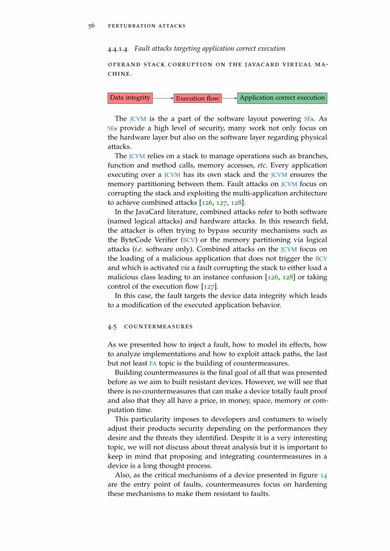
56 perturbation attacks
4.4.1.4 Fault attacks targeting application correct execution
operand stack corruption on the javacard virtual ma-chine .
Data integrity Execution flow Application correct execution
The JCVM is the a part of the software layout powering SEs. AsSEs provide a high level of security, many work not only focus onthe hardware layer but also on the software layer regarding physicalattacks.
The JCVM relies on a stack to manage operations such as branches,function and method calls, memory accesses, etc. Every applicationexecuting over a JCVM has its own stack and the JCVM ensures thememory partitioning between them. Fault attacks on JCVM focus oncorrupting the stack and exploiting the multi-application architectureto achieve combined attacks [126, 127, 128].
In the JavaCard literature, combined attacks refer to both software(named logical attacks) and hardware attacks. In this research field,the attacker is often trying to bypass security mechanisms such asthe ByteCode Verifier (BCV) or the memory partitioning via logicalattacks (i.e. software only). Combined attacks on the JCVM focus onthe loading of a malicious application that does not trigger the BCV
and which is activated via a fault corrupting the stack to either load amalicious class leading to an instance confusion [126, 128] or takingcontrol of the execution flow [127].
In this case, the fault targets the device data integrity which leadsto a modification of the executed application behavior.
4.5 countermeasures
As we presented how to inject a fault, how to model its effects, howto analyze implementations and how to exploit attack paths, the lastbut not least FA topic is the building of countermeasures.
Building countermeasures is the final goal of all that was presentedbefore as we aim to built resistant devices. However, we will see thatthere is no countermeasures that can make a device totally fault proofand also that they all have a price, in money, space, memory or com-putation time.
This particularity imposes to developers and costumers to wiselyadjust their products security depending on the performances theydesire and the threats they identified. Despite it is a very interestingtopic, we will not discuss about threat analysis but it is important tokeep in mind that proposing and integrating countermeasures in adevice is a long thought process.
Also, as the critical mechanisms of a device presented in figure 14
are the entry point of faults, countermeasures focus on hardeningthese mechanisms to make them resistant to faults.

4.5 countermeasures 57
4.5.1 Space redundancy
The space redundancy aims at protecting the device data integrityby storing it twice. Therefore, by regularly checking the differencebetween the two versions of the same data, the device can detect ifa fault was induced on it. This solution is very naive and costly asit doubles the needed space for storing data. A refinement is to onlyduplicate sensitive data. However, as we have seen in section 4.4.1.2for the memory partitioning, in some cases there are a lot of data toprotect (all the PTEs in this case).
A less costly solution is to use error correcting codes. The most fa-mous is the parity bit [129, 130]. This solution is usually used in DDRversion 4 (DDR4)-Synchronous Random Access Memorys (SRAMs) andin the cache memories [131]. Also, to improve the security, better errorcorrecting codes have been presented and use to protect AES imple-mentations such as multiple parity bits [132], non-linear codes [133]or non-linera r-bits long codes [134].
Despite error correcting codes are an efficient countermeasure againstfaults, they do not protect against multiple faults. Indeed, it is possi-ble for an attacker to fault both the data and the parity bit or its verifi-cation. This example shows that countermeasures against faults doesnot make FA totally inefficient but harder to achieve as they increasethe number of faults needed to attack the system.
Moreover, in order to secure an implementation against all physicalattacks (side-channel and perturbations), it is important to keep inmind that error correcting codes does not suits well with side-channelmasking countermeasures [135].
4.5.2 Operation duplication
The operation duplication is in some way similar to the space redun-dancy but instead of duplicating a data it duplicates an operation.This can be done in several ways as shown in figure 33.
input
F F
= ?
output error
(a) Full duplication
input
F1
F2 F2
= ?
output error
(b) Partial duplication
input
ENC
DEC
= ?
erroroutput
(c) Encryption/decryp-tion duplication
Figure 33: Operation duplication possible implementations

58 perturbation attacks
This figure presents three ways of implementing the duplicationof an operation F. Figure 33a shows the most naive way which dupli-cates the full operation while figure 33b presents a partial duplication.The partial duplication is less costly than the full part and is usuallyused to secure a sensitive part of the algorithm. As this countermea-sure is usually used to protect cryptographic algorithm, it is possiblethat both the encryption and the decryption are implemented, there-fore it is possible to use both to realize a verification as presentedin figure 33c. This duplication is interesting as it does not require toreally duplicate a function.
As mentioned above, this countermeasure does not make FAs com-pletely inefficient but make harder any FA targeting the operation astwo faults are needed. Indeed, either both versions of the sensitiveoperation have to be faulted or a version of the operation and thecompare operation.
4.5.3 Infection countermeasure
The infection countermeasure is a refinement of the duplication coun-termeasure which aims at protecting against the DFA when the com-pare operation is bypassed. The idea is to diffuse the fault effect in theoutput to avoid any information leakage due to the fault invariant. Inthis case, even with two faults, the DFA is not a viable attack.
In practice, the idea is to identify the fault between the outputsout1 and out2 and to use a diffusion function D to generate a maskfrom the fault which is applied to the outputs as presented in equa-tions (24) and (25). This can also be done on intermediate states.
out ′1 = D(out1 ⊕ out2)⊕ out1 (24)
out ′2 = D(out1 ⊕ out2)⊕ out2 (25)
D(0) = 0 (26)
Equation: Infection countermeasure
With a good diffusion function D, the fault will propagate in theoutput and no information will be usable by the attacker. This ismostly used in AES. The only constraint on D is shown in equa-tion (26). Several diffusion functions are proposed in [136, 137] andthe need of randomness in D was highlight in [138].
4.5.4 Code hardening
The code hardening is a particular kind of countermeasure which aimat adding software countermeasures in a code to protect it againstcontrol flow attacks. At first, these works aimed at detect and protectagainst software attacks such as Return-Oriented Programming (ROP)attacks [139] but appeared to be suitable for protecting against faultattacks targeting the control flow.

4.5 countermeasures 59
These countermeasures face many challenges both on their designand on their implementation. Indeed, the program is protected by theprogram and moreover, the integration of countermeasures must becompliant with the compilation process of software which realizesoptimizations that can nullify the countermeasures efficiency.
As a consequence, the integration of such countermeasures has tobe adapted to the compilation process as shown in figure 34 with theimpact it can have on development time and optimization.
source.c
.javacompilation
binary/bytecode.o
.class
link
executable.elf
.cap
source tosource [140]
compilerassisted [141]
binaryrewriting [142]
linktime [143]
Figure 34: Software countermeasures integration in the compilation process.
This figure shows the different steps of the compilation for .elf
(Linux executable file) and .cap (JavaCard executable file) files. Thisprocess is simplified but it able to highlight the different steps wherea software countermeasure can be integrated into a software imple-mentation.
Regarding the countermeasures themselves, several solutions areproposed.
One of them is the signature of blocks [144]. This method relieson the verification of signature at different moments of the programexecution. The blocks can have different granularity, they can be ba-sic blocks [145] or C statements [140]. Also, the signature verificationcan be implemented in different ways: it can rely on hardware mech-anisms like the performance counter [146], it can be fully integratedin software in the program [147, 148] or in a virtual machine as pro-posed for the JCVM in [142, 149, 150].
Another solution aims at complementing the signature of blocks.Indeed, the signature of blocks able to detect control flow errors froma block to another but not inside the block. A solution to detect intra-block control flow error is the usage of step counters [151]. The prin-ciple of this solution is to initialize a counter N when entering a blockwhich is equal to the number of instructions to execute in the block.Each time an instruction is executed, this counter is decreased by 1
and its value is check at the end of the block. At this moment, its valuemust be 0 otherwise it means that an instruction has been skipped orreplayed. This countermeasure is summarized in listing 4.1.

60 perturbation attacks
N = I+1;
instruction0;
N--;
instruction1;
N--;
.
.
.
instructionI;
N--;
if(N != 0)
error();
Listing 4.1: Step counter countermeasure on a block of I instructions
4.5.5 Sensors
Another way to protect a device or an implementation against FAs isto detect that there is a fault attempt. As mentioned in introduction,perturbation attacks rely on pushing the device out of its nominaloperation point. Therefore, a proposed solution is to integrate sensorsin the device which will detect if there is any abnormal perturbationtargeting the device.
Nowadays, there is a sensor for almost every injection mediums:EMPs [152], supply voltage [153], temperature [154], light [155], FBBI [156]and even a (patented) package penetration sensor [157]. However,sensors are tough to calibrate as they aim at detecting with the bestprobability a perturbation attempt while having the lowest error ratepossible. An important issue is that a perturbation might be detectedwithout it to be malicious. Also, the physical environment of a chipdepends of its usage and it can change during its lifetime making itvery complicated to efficiently calibrate a perturbation sensor.
Finally, as the possible reaction of device detecting a perturbation isto destroy itself, it is possible to realize Deny Of Service (DOS) attacks.
4.6 conclusion on perturbation attacks
Perturbation attacks are an important threat for digital devices. Theycan modify the behavior of a device during its execution and there-fore, break security mechanisms or break cryptographic algorithmsecurity.
Despite they are an efficient way for attacking, they are not straight-forward to understand, realize nor exploit. For this reason manyworks focus on discovering way to inject faults, characterizing theirimpact on the devices behavior, analyze this impact on secure imple-mentations and either exploit them or protect against them. All thesetopics are a research field on their own showing the diversity of highlevel skills needed for fully understanding fault attacks.

4.6 conclusion on perturbation attacks 61
The consequence is that, despite their efficiency, fault attacks aredifficult to exploit and to mitigate, making the design and develop-ment of secure devices resistant to fault attacks a highly skilled pro-cess.


Part II
C O N T R I B U T I O N
...but always keep going.


5FA U LT E F F E C T C H A R A C T E R I Z AT I O N O N S Y S T E M SO N C H I P
When the world shoves you around, you just gotta stand up and shove back.It’s not like somebody’s gonna save you if you start babbling excuses.
— Roronoa Zoro (One Piece)
abstract
This chapter presents my contribution regarding the fault model char-acterization on SoCs. The introduced elements are the SoC model, theattacker model, the device setup with the test codes and the tested tar-gets, the perturbation benches and the analysis tools. A paper basedon this work was published in WISTP 2019 Conference [158].
Contents
5.1 SoC modeling 66
5.2 Attacker model 66
5.3 Experimental method 67
5.3.1 Top-down approach 67
5.3.2 Target setup 68
5.4 Determining the faulted element 73
5.5 Conclusion 75
65

66 fault effect characterization on systems on chip
As this thesis aims at evaluating the security of SoCs against FAs, thefirst step consists in characterizing how these devices are perturbedas shown in figure 16.
However, because SoC are complex and embed many modules, mycontribution only focus on characterizing the CPU behavior againstFAs. As mentioned in section 2.3.2, the CPU is the cornerstone of thedevice and therefore an interesting target.
The characterization relies on a model of this target. The modelprovides information about the behavior of the device and thereforethe elements that can be perturbed. The role of the characterization,is to determine which elements are perturbed and how.
Therefore, this chapter presents the modeling of a SoC, the attackermodel we consider (and therefore our analysis frame), the top-downapproach we use for characterizing fault effects and the target setup.
5.1 soc modeling
A modern CPU architecture is presented in figure 10 (section 2.3.2.1)and this model is used for our characterization process. The impor-tant things to have in mind are that:
• the CPU embeds a pipeline which fetches, decodes and executesinstructions;
• the pipeline is connected to a bank of registers storing the datamanipulated by the instructions;
• data and instructions are read from a memory subsystem com-posed of cache memories. These cache memories can either storedata, instruction or both;
• the data and instructions addresses used by the core are virtualand translated by the MMU during memory accesses;
• everything is connected via buses.
All these Micro-Architectural Blocks (MABs) are involved during aprogram execution and can be perturbed during a FA. Our aim is todetermine which elements are perturbed regarding different injectionmediums and how.
5.2 attacker model
Regarding the CPU architecture, one cannot access and debug everyMABs. Considering modern SoCs are embedded in smartphones, a real-istic attacker aiming at using fault for weakness its security will startby characterizing the fault effects on a smartphone he bought itself.
In this situation, the attacker access to the device is limited to flash-ing the OS and executing self-made programs. As this thesis is a firststep in SoC characterization, we consider an attacker which can onlyexecute its programs on the target to characterize the device behavior.

5.3 experimental method 67
As a consequence, our method match this constraints as we onlyexecute user level programs. In this chapter we present the methodusing such programs and in the following chapters we demonstratethat this method able to deduce information about perturbation ef-fects and the this information is relevant for attacking security mech-anisms.
However, to challenge the method we present, we also realized amicro-architectural characterization using a custom OS and Join TestAction Group (JTAG).
5.3 experimental method
As mentioned above, the experiment method for fault characteriza-tion is based on the execution of user level programs. However, itaims at providing a information about the ISA and the micro-architecturalbehaviors of the target. To reach this objective, the method is based ona top-down analysis we link the MABs to the program elements (thedata and the instructions) and discriminate the affected MABs usingvarious test program.
5.3.1 Top-down approach
During a Fault Injection (FI), one or several MABs are disturbed. Asthey can all be perturbed during a fault injection, the full fault effectcharacterization can be a complicated process. However, accordingto the previous works on SEs, in most cases, the fault affects only asingle MAB, like the cache or the pipeline. We actually verified this as-sumption on modern CPUs. Under this simplified paradigm, the faultcharacterization problem aims at determining which MAB is faultedand how.
To reach our objective, the proposed method consists in realizing afault during a test program execution and in determining the micro-architectural fault that can explain the observed misbehavior.
Summarized in figure 35, the general idea is to apply a top-downapproach. We start by determining whether the fault affects the dataor the instructions, this corresponds to the ISA level. Once we knowwhich element is affected, we determine which of its MABs is faulted.To discriminate which element is faulted, we repeatedly execute thesame instructions on a known state CPU.
ISA
Micro-Arch
Faulted program
Faulted data
Registers Memory
MMU Bus Cache
Faulted instruction
Pipeline
Decode Execute
Memory
Fetch Bus Cache MMU
Figure 35: Fault effect characterization overview

68 fault effect characterization on systems on chip
Disturbing the program execution will give a distribution of faultedvalues. The next step consists in determining whether these faultedvalues come from a fault on the manipulated data or on the instruc-tions.
Once we know if the data or the instructions are faulted, it is possi-ble, from the fault model on these elements to determine which MABs
have been faulted. In the case of a register corruption, it is straightfor-ward that the registers are faulted. In the case the wrong instruction isfetched from the memory, either the cache has loaded the wrong dataor the MMU has failed the address translation. If an instruction cor-ruption is observed, the fault affects either one of the pipeline MABs
or the cache or the instruction bus.
5.3.2 Target setup
For the fault model characterization, two important things must bedefined: the test program and the initial values of the CPU registers.Each test program consists in the repetition of an instruction. How-ever, as they execute on a complex system, they are wrapped in aprogram as described in figure 36.
1 2 3 4 test program 5 6 7 8
Programinitialization
Contextsaving
Registersinitialization
Triggerup
Triggerdown
Readregisters
Restorecontext
SendresponseFault
injection
Figure 36: General program organization
This figure shows the program wrapping the test program. It aimsat initializing the processor state before executing the test programand to send back the relevant data (usually the registers values) andprocessing the triggers. Also, as it has to communicate with an ex-ternal component (usually the PC managing the experiment), it mustsave its execution context and restores it after the test as we do notwant this part of the program to be faulted.
5.3.2.1 Test programs
The method for determining a fault model consists in executing achosen program on a known state. By executing the program, thestate will change in the succession of states. Perturbing the executionmight create a fault. Then a state in the middle of the execution willbe faulted, and all the successive states will also be faulted.
To determine a fault model, the method consists in comparing theexpected final state with the faulty one. Repeating the comparisonwith various initial states or programs allow to determine the faultmodel.
This approach is effective but presents an issue. Once a faulty stateappears in the computation, the program continues. This induces thatthe faulty final state is not a consequence of the fault, but a conse-quence of the fault and the execution of the program on it as shown
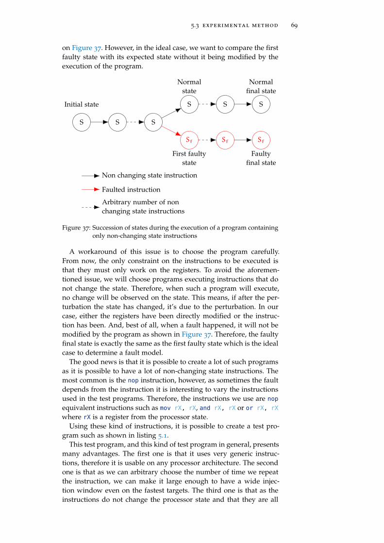
5.3 experimental method 69
on Figure 37. However, in the ideal case, we want to compare the firstfaulty state with its expected state without it being modified by theexecution of the program.
S S S
S
Sf
S
Sf
S
Sf
Initial state
Normalfinal state
Faultyfinal state
First faultystate
Normalstate
Non changing state instruction
Faulted instruction
Arbitrary number of nonchanging state instructions
Figure 37: Succession of states during the execution of a program containingonly non-changing state instructions
A workaround of this issue is to choose the program carefully.From now, the only constraint on the instructions to be executed isthat they must only work on the registers. To avoid the aforemen-tioned issue, we will choose programs executing instructions that donot change the state. Therefore, when such a program will execute,no change will be observed on the state. This means, if after the per-turbation the state has changed, it’s due to the perturbation. In ourcase, either the registers have been directly modified or the instruc-tion has been. And, best of all, when a fault happened, it will not bemodified by the program as shown in Figure 37. Therefore, the faultyfinal state is exactly the same as the first faulty state which is the idealcase to determine a fault model.
The good news is that it is possible to create a lot of such programsas it is possible to have a lot of non-changing state instructions. Themost common is the nop instruction, however, as sometimes the faultdepends from the instruction it is interesting to vary the instructionsused in the test programs. Therefore, the instructions we use are nop
equivalent instructions such as mov rX, rX, and rX, rX or or rX, rX
where rX is a register from the processor state.Using these kind of instructions, it is possible to create a test pro-
gram such as shown in listing 5.1.This test program, and this kind of test program in general, presents
many advantages. The first one is that it uses very generic instruc-tions, therefore it is usable on any processor architecture. The secondone is that as we can arbitrary choose the number of time we repeatthe instruction, we can make it large enough to have a wide injec-tion window even on the fastest targets. The third one is that as theinstructions do not change the processor state and that they are all

70 fault effect characterization on systems on chip
or r3, r3;
/*
* Arbitrary number of repetitions
*/
or r3, r3;
Listing 5.1: Example of a test program for fault characterization
the same, it does not matter which one is perturbed, avoiding anysynchronization issue. Finally, these instructions are “data processinginstructions” which means that they do not fetch data from memory.Regarding our method presented in figure 35, this reduce the analysisframe as, in this case, the “memory” branch from the “faulted data”node cannot be reached.
However, this test program also presents some drawbacks. The firstone is that, as it does not fetch data from the memory, we are not ableto determine if the fault targets this path. This test requires anothertest program presented in listing 5.2.
str r2, [r4];
ldr r2, [r4];
/*
* Arbitrary number of repetitions
*/
str r2, [r4];
ldr r2, [r4];
Listing 5.2: Example of a test program for fault characterization on memoryaccesses
This test program is a bit different from the previous one as it isbased on two instructions. The reason is that memory access instruc-tion are always changing state instructions. For instance, if the valuein r2 is different from the value at the address stored in r4, a load ora store instruction will erase this difference. The consequence is thatif we only do store instructions, a fault in the memory will be over-written, while if we only do load instructions, a fault in the registerswill be overwritten. A solution could be to do two experiments, onewith stores and one with loads. The test program presented in list-ing 5.2 allow us to determine if there is a fault in any case with oneexperiment. This is a consequence of the fact that the repetition of thestore and the load is a non-changing state sequence of instructions.
The second drawback of the test program presented in listing 5.1 isthat it is not able to detect instructions skips or repetitions. As theseare a common fault model, it is important to take them into account.The detection of such faults is usually done by faulting a test programincrementing a register such as presented in listing 5.3.
This program is able to simply determine if an instruction, or sev-eral, was skipped or repeated by checking the value of r8. However,this test program presents some issues. The first issue is that some

5.3 experimental method 71
add r8, #1;
/*
* Arbitrary number of repetitions
*/
add r8, #1;
Listing 5.3: Example of a test program for instruction skip/repetition char-acterization
instruction corruptions can be considered as a skip or repetitions, inparticular in the case the immediate value #1 is forced to #0, #ff (−1)or any other value or if the incremented register is modified. There-fore, this test program must be used after it has been determined thatthis kind of faults does not appear. This is easily done using the testprogram presented in listing 5.1.
The second issue of the program presented in listing 5.3 is that theused instructions are no non-changing state instructions. The conse-quence is that if a different fault than instruction skip or repetition isachieve, it will be harder to identify it than with the first test programpresented in listing 5.1.
The third issue of the test program presented in listing 5.3 is thatthe number of increments is limited by the register size to avoid over-flows. This is more an issue on low-width processors and only impactinstruction repetitions but it is important to keep it in mind.
The final issue of the test program presented in listing 5.3 is that itis not able to detect instruction repetition with replacement fault mod-els. In this fault model, an instruction (or several) is repeated whileanother one (usually the immediately following one) is skip instead.Regarding the test program in listing 5.3, repeating a add r8, #1 in-struction which replaces a add r8, #1 does not induce a fault. There-fore, the solution is to vary the incremented registers such as pre-sented in listing 5.4.
add r5, #1
add r6, #1;
add r7, #1;
/*
* Arbitrary number of repetitions
*/
add r5, #1;
add r6, #1;
add r7, #1;
Listing 5.4: Example of a test program for instruction repetition with re-placement characterization
This program is able to determine if instruction where replacedby others simply by checking the registers values. However, most ofthe time, not only one instruction is replaced but several, this comesfrom the fetching of a pack of instruction. Therefore, this program

72 fault effect characterization on systems on chip
might not be able to detect large packs of instructions replaced as itis limited by the number of available registers.
With these test programs, it is possible to determine all the knownfault model at the ISA level targeting data processing instructionsand memory accesses instructions. However, these programs does notgive information about branch instructions. The reason is that theseinstructions are complicated to analyze as a fault affecting them canlead to the execution of unknown code. However, data processing in-structions and memory accesses instructions compose an importantpart of programs, making their analysis relevant.
5.3.2.2 Target initial values
To have a simple fault characterization, the initial values must fit someproperties. They must be all different (equation (27)) and any logicalor arithmetical simple operation between them must be identifiable(equation (28)). In other words, if we observe a faulted value v ∈
[[0, 2n − 1]] where n is the bit size we consider, we want to be able todetermine the involved initial values and the logical or arithmeticaloperation without any ambiguity.
∀(i, j) ∈ [[0,k− 1]]2, i 6= j =⇒ xi 6= xj (27)
Equation: Difference between all registers initial values property
∀v ∈ [[0, 2n − 1]], ∃!(i, j,o) ∈ [[0,k− 1]]2 ×O such as o(xi, xj) = v
(28)
Equation: No arithmetical links between registers initial values property
where xi is the ith initial value, k is the number of registers and O
the set of operations we consider.To match most of the modern CPUs the operations we consider for
our initial values are the logical OR, AND, XOR and the arithmetical ADDand SUB. We realized the characterization on several targets and ourconstraints are n = 32 or n = 64 and k = 10 or k = 16.
Create a set of initial values matching the properties presented inequations (27) and (28) with these parameters is not complicated, ran-domly generating the values work. However, randomly generatedvalues are not easy to analyze for a human, so we built the xi aspresented in equation (29).
xi = 2i + 2n − 2n/2 − 2i+n/2 (29)
Equation: Registers initial values construction

5.4 determining the faulted element 73
The corresponding initial values for our registers are presented intable 1. However, despite the fact these values fill the properties pre-sented above and are easily identifiable for a human, their construc-tion impose a constraint on the number of observable registers whichis k 6 n/2. In other word, the number of register we can monitormust be lower than half of the bit size of these registers.
Register Initial values (32 bits) Initial values (64 bits)
r0 0xfffe0001 0xfffffffe00000001
r1 0xfffd0002 0xfffffffd00000002
r2 0xfffb0004 0xfffffffb00000004
r3 0xfff70008 0xfffffff700000008
r4 0xffef0010 0xffffffef00000010
r5 0xffdf0020 0xffffffdf00000020
r6 0xffbf0040 0xffffffbf00000040
r7 0xff7f0080 0xffffff7f00000080
r8 0xfeff0100 0xfffffeff00000100
r9 0xfdff0200 0xfffffdff00000200
Table 1: Target initial values for fault characterization considering ten regis-ters
The issue with these values is that in the case of the execution oftest programs for instruction skip and repetition characterization (list-ings 5.3 and 5.4), the registers overflow can be reached quickly. Withthese programs, it can be interesting to simply initialize the registersto 0.
5.4 determining the faulted element
To determine the faulted MAB, we rely on the available registers ob-servation and the executed instructions knowledge. The way they arefaulted gives information about the faulted element.
Disturbing the program execution will give a distribution of faultedvalues in the registers. The next step consists in determining whetherthese faulted values come from a fault on the manipulated data or onthe instructions. Indeed, the execution of the nth program instructionby the CPU can be modeled such as in equation (30):
sn+1 = insn(sn) (30)
Equation: State computation in a CPU
where sn+1 is the CPU state after the execution of the nth instruc-tion insn. An instruction is composed of three elements: an opcodeencoding the operation to do, a reference to the destination registerand reference(s) to the operand(s). These operands can be registers

74 fault effect characterization on systems on chip
or immediate values. Depending on the architecture, the encoding ofthis information may vary but they are always present.
When there is a fault during an instruction execution, we assumehere that it either applies on the data or on the instruction. We exper-imentally verified this assumption. Therefore, the faulted instructionexecution can be modeled such as in (31).
˜sn+1 = ˜ins(sn) (31)
Equation: Faulted state computation in a CPU
where x denotes the faulted representation of x. From this represen-tation, we can define the fault model fdata on the data as introducedin (32), and the fault model fins on the instruction as presented in(33).
sn = fdata(sn) (32)
Equation: Data fault model
˜ins = fins(ins) (33)
Equation: Instruction fault model
These fault models can have different descriptions to match withthe different underlying fault causes. The data fault types and theircorresponding MABs are presented in table 2.
Faultedelement
Data
Faulttype
Registercorrup-
tionMemory corruption Bad fetch
FaultedMAB
Registers CacheDatabus
Cache MMU
Table 2: Data fault models
Based on the CPU model and table 2, it is possible, from these faulttypes, to determine which MABs has been faulted. In the case of aregister corruption, it is straightforward that the registers are faulted.If there is a memory corruption, the cache storing the data or the databus is faulted. In the the “bad fetch” case, either the cache has loadedthe wrong data or the MMU has failed the address translation.
For the instructions, the fault types, presented in table 3, are cor-ruption and bad fetch.

5.5 conclusion 75
Faultedelement
Instruction
Faulttype
Corruption Bad fetch
FaultedMAB
Pipeline Cache Bus Cache MMU
Table 3: Instruction fault models
If an instruction corruption is observed, the fault affects either oneof the pipeline MABs, the cache or the instruction bus. In the case of abad fetch, either the instruction cache has loaded the wrong instruc-tion or the address translation has failed.
Regarding the test code presented above, the data fault models“memory corruption” and “bad fetch” cannot appear as there is nodata fetched from the memory. Therefore, we can focus on the remain-ing fault models and this is enough for determining which elementamong the registers, the pipeline or the memory has been faulted.
5.5 conclusion
This chapter presented the method and the theory about the faulteffect characterization on SoCs.
Despite several methods exists since a long time, this work is thefirst synthesis on fault characterization on a digital device. Indeed,even if it was presented in the scope of SoCs, this method perfectlyfits with the analysis of a simpler device such as a SE. The main dif-ference will come from the model of the target, but a model of a SE ispresented in figure 4.
With this method, we were able to characterize faults at the ISA andmicro-architectural level. Therefore, the next chapter presents how weapplied this method on SoCs.


6E X P E R I M E N TA L W O R K
Hard work and efforts never betray.
— Gaï Maito (Naruto)
abstract
This chapter presents our experimental setup and the characterizationresults on the three chosen targets: the BCM2837, the BCM2711b0
and the Intel Core i3-6100T. The characterization aims at defining theoptimal injection parameters and the associated effects at the ISA andmicro-architectural level for each target.
Contents
6.1 Practical work setup 78
6.1.1 Attack benchs 78
6.1.2 Evaluated devices 81
6.1.3 Tools 85
6.2 BCM2837 characterization 91
6.2.1 Hot-spots maps 92
6.2.2 Analyzer results 94
6.2.3 Micro-architectural analysis using a testprogram 100
6.2.4 Micro-architectural analysis on a baremetalsetup with JTAG 104
6.2.5 Conclusion on the BCM2837 characteriza-tion 107
6.3 BCM2711b0 characterization 108
6.3.1 Hot-spots maps 108
6.3.2 Analyzer results 109
6.3.3 Conclusion on the BCM2711b0 characteri-zation 113
6.4 Intel Core i3 characterization 114
6.4.1 Hot-spots maps 114
6.4.2 Analyzer results 116
6.4.3 Conclusion on the Intel Core i3-6100T 119
6.5 Characterization conclusion 119
77

78 experimental work
As presented in chapter 4, characterization is the former step inevaluating and securing devices against fault attacks. As we aim atevaluating the security of SoCs, we need to realize this characteriza-tion. The method we use for characterizing fault effects was presentedin chapter 5. In this chapter, we present the practical application ofthis method by introducing our experimental setup, the targets weworked on and the characterization results we obtained on them.
The work presented in these chapters are part of several paperspublished at WISTP 2019 [158] or submitted for publication [159, 160].
6.1 practical work setup
Before presenting our experimental results, it is important to intro-duce the tools we used for realizing our characterizations. As faultinjections are probabilistic attacks and therefore, time consuming, thebench aims at autonomously managing fault injection campaigns onthe Device Under Test (DUT).
6.1.1 Attack benchs
A generic attack bench is presented in figure 38.
DUT
Axes
Injector
PC
Energysupplier
Signalmanager
position
Eperturb
drive
communicate
drive
configure
configure
voltage
signal
trigger
E Perturbation
Data link
Mechanical interaction
Analog signal
Figure 38: Generic attack bench organization and interactions
As the bench aims at perturbing the DUT, it has a central role in itsorganization. The DUT executes the test code we want to fault.
The perturbation is induced by the injector, there are different in-jectors regarding the injection medium, and, in the case of softwareinduced fault attack, the injector is the DUT itself. The injector can be

6.1 practical work setup 79
configured to tweak the different injection parameters. These param-eters vary from a medium to another. During this thesis, we focusedon EM and laser perturbations.
In some cases, axes are needed to move either the DUT or the in-jector. This able to test different positions during EM, laser or FBBI
injections. This is specific and quite time consuming as it implies amechanical movement. Being able to optimize the path of the injectorover the DUT can therefore be very time saving.
An important component of the bench is the energy supplier. In-deed, as the bench aims at being autonomous, it must manage thecase where the perturbation crashes the DUT. When the DUT is crashed,a reboot of the system is needed and it is done by the energy supplier.
Another important component is the signal manager which deter-mines when doing the injection and sends a trigger signal to the in-jector. In the ideal cases, the trigger signal directly comes from theDUT and is transmitted to the injector. However, in some complicatedcases (on a closed platform for instance), such signal is not available.Therefore, the signal manager must analyze the DUT behavior and, viapattern recognition for instance, generates the trigger signal for theinjector. This component is very important in current attack benchsas its performances (speed, success rate, jitter and accuracy) able aprecise synchronization with the device. This component is wherethe most added value of an attack bench comes from. In our case,we always managed to output a trigger signal so we simply use anoscilloscope.
The last component is the PC, it aims at managing the fault injec-tion campaigns, configures every components, drives the necessaryelements and stores the results of the experiments. It keeps commu-nicating with the DUT when it is possible to ensure that everything isgoing as expected.
Also, most of the time, an oscilloscope is added to acquire andobserve the analog signals.
6.1.1.1 ElectroMagnetic bench
The first bench we used is the EM bench presented in figure 39.This bench is composed with all elements introduced in figure 38.
On this figure, the DUT is an Intel Core i3. The other evaluated tar-gets are presented in the following section. As it is an electromag-netic bench, a probe is placed over the DUT to generate the EM waves.This probe is home-made and is composed of a copper wired rolledaround a ferrite.
The energy supplier, which manages the reset of the DUT, is com-posed of an Arduino board.
The signal manager is handled by an oscilloscope, which also ac-quire the analog signals mentioned in figure 38. For the characteriza-tion, as we master the targeted program, we configure the DUT so itoutputs a trigger signal just before starting the test program. There-fore, we do not need any pattern recognition mechanism in our signalmanager.
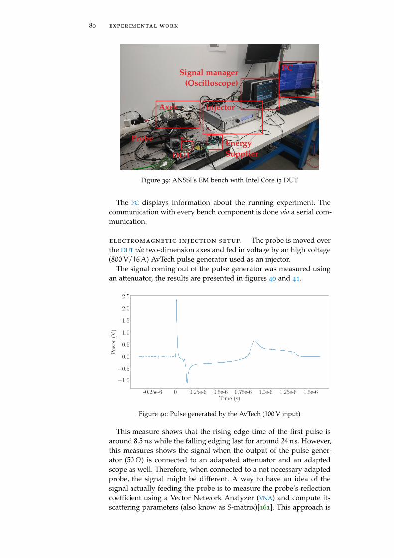
80 experimental work
DUT
Axes
Energy
Supplier
Injector
Signal manager
(Oscilloscope)
PC
Probe
Figure 39: ANSSI’s EM bench with Intel Core i3 DUT
The PC displays information about the running experiment. Thecommunication with every bench component is done via a serial com-munication.
electromagnetic injection setup. The probe is moved overthe DUT via two-dimension axes and fed in voltage by an high voltage(800V/16A) AvTech pulse generator used as an injector.
The signal coming out of the pulse generator was measured usingan attenuator, the results are presented in figures 40 and 41.
-0.25e-6 0 0.25e-6 0.5e-6 0.75e-6 1.0e-6 1.25e-6 1.5e-6Time (s)
−1.0
−0.5
0.0
0.5
1.0
1.5
2.0
2.5
Pow
er(V
)
Figure 40: Pulse generated by the AvTech (100V input)
This measure shows that the rising edge time of the first pulse isaround 8.5ns while the falling edging last for around 24ns. However,this measures shows the signal when the output of the pulse gener-ator (50Ω) is connected to an adapated attenuator and an adaptedscope as well. Therefore, when connected to a not necessary adaptedprobe, the signal might be different. A way to have an idea of thesignal actually feeding the probe is to measure the probe’s reflectioncoefficient using a Vector Network Analyzer (VNA) and compute itsscattering parameters (also know as S-matrix)[161]. This approach is

6.1 practical work setup 81
-2 2 4 6 80.25 1.1 3.5
·10−8
0
2
4
Time (s)
Pow
er(V
)
Figure 41: Pulse generated by the AvTech zoomed on the first peak (200Vinput)
relevant considering the probe as an isolated system, but, during faultinjections, the probe is close to the circuit and therefore it cannot beconsidered isolated, we are in a near-field situation regarding elec-tromagnetic theory. In our case, instead of considering the probe asthe system to characterize, we will consider the probe+circuit as thesystem. Indeed, during fault injections this system is isolated fromexternal electromagnetic perturbations and we therefore can measureits scattering parameters. These parameters represent the reflection ofthe device for various input signal frequencies. Identifying frequen-cies where the reflection is minimal means the system absorption ismaximal which means it is at this frequency that the system absorbsthe highest amount of energy. This energy can therefore either beconverted into heat via Joule’s effect or it can influence the circuit be-havior inducing faults. Doing so, we should be able the most efficientfrequency to use for our injector to maximize our fault probability.
As mentioned, this approach focus on the probe+circuit system,which means it must be redone for every tested target. However, thisis an on-going work and we do not have relevant results to presentyet.
6.1.1.2 Laser bench
For LFIs, our bench is composed of a focused laser bench with a 50 x
long distance lens and the wave length is around 970nm. For beingable to inject faults, the chip backside must be thinned around 150µm.In our experiments, we used a pulse width of 20ns.
6.1.2 Evaluated devices
Now that all the equipment are set up, we must determine targetsto work on. As we want to evaluate the security of modern SoCs, wenaturally target such devices. However, as we want to realize a charac-terization work, the targets must be open enough so we can develop

82 experimental work
and execute our test programs on it. Also, we want the targets to berepresentative of the available SoCs on the market.
Therefore, the targets we have chosen are:
• The BCM2837 powering the Raspberry Pi 3 model B board, thisboard is widely used in IoT projects and has an important com-munity.
• The BCM2711b0 powering the Raspberry Pi 4, this board is thelatest version of the Raspberry Pi. It was chosen so we are ableto compare the results we obtain on very similar devices (theBCM2837 and the BCM2711b0).
• The Intel Core i3-6100T powering a desktop PC, this target hadbeen chosen to test our characterization method on a x86 archi-tecture. This was the first time a x86 architecture device wascharacterized against fault injections.
With these three targets, we have a representative set of SoCs withboth ARM and x86 architectures. During our experiments, these de-vices are powered by a Debian 9 OS. The influence of the OS is dis-cussed in section 6.2.4.1.
6.1.2.1 BCM2837 (ARM)
The first target is the BCM2837 powering the Raspberry Pi 3 model Bboard presented in figure 42.
BCM2837
Figure 42: Raspberry Pi 3 model B board
This board embeds of 1GB of RAM running at 900MHz, a 40-pinheader as General Purpose Inputs/Outputs (GPIOs), a 2.4GHz wire-less connection (Wi-Fi), an ethernet port, an High-Definition Multime-dia Interface (HDMI) port, USB 2.0 ports, an analog audio-video jackport, a camera interface and a socket for a microSD card. Its modulesshow the multi-purpose orientation of its processor, the BCM2837.
This SoC is printed with a 28nm technology, it is composed of fourcores with four threads each. The cores are ARM Cortex-A53 coresand can run at a maximum frequency of 1.2GHz. In total, this SoC
has a cache memory of 512 kB. Its layout is in the figure 43.

6.1 practical work setup 83
Cores
Figure 43: BCM2837 infrared backside layout image
This IR backside layout image was acquired after opening the BCM2837.The four cores are easily identifiable and covers around 25% of thedie surface. The rest of the die corresponds to the other integratedmodules (GPU, video core, etc) and the buses.
It is interesting to notice that the die does not fill the complete chippackage as shown in figure 44.
Figure 44: Open BCM2837 with the chip in its package
This figure shows that the die is placed in the center of the chip. Therest of the chip is constituted of wire-boudings used for connectingthe die to the BGA. This is important as, during our experiments, weuse EMPs to perturb the component over all its package.
6.1.2.2 BCM2711b0 (ARM)
The second target we worked on is the BCM2711b0 powering theRaspberry Pi 4 board presented in figure 45.
This board is also composed of a RAM (from 1GB up to 4GB), a40-pin GPIOs as on the Raspberry Pi 3 model B, a Bluetooth and aBluetooth Low Energy interface, a 2.4GHz and 5GHz Wi-Fi connec-tions, two micro-HDMI ports, a gigabit Ethernet port and a socket fora microSD card. This is very similar with the Raspberry Pi 3 model Bbut with more up to date technologies.

84 experimental work
BCM2711b0
Figure 45: Raspberry Pi 4 board
The BCM2711b0 SoC, engraved in 28nm as the BCM2837, embedsa four ARM Cortex-A72 cores with four threads each. The cores canrun at a maximum frequency of 1.5GHz. The processor integrates atotal cache memory of 1MB. Its layout is shown in figure 46.
Cores
Mixed cache
Figure 46: BCM2711b0 infrared backside layout image
This picture was acquired using infrared imaging after having re-moved the metal protection of the chip. The four cores are easily iden-tifiable so is the mixed cache memory. As on the BCM2837, the restof the die corresponds to the other integrated modules.
6.1.2.3 Intel Core i3 (x86)
The last evaluated target is the Intel Core i3-6100T introduced in fig-ure 47.
It is printed in a 14nm technology and is composed of two coreswith four threads each. The maximum frequency of the cores is 3.2GHz.The die also integrates a graphical processor thus the classical oneand 3MB of cache memory.

6.1 practical work setup 85
Figure 47: Intel Core i3 SoC
As this chip is modular, it is not link to a specific board. Therefore,for our experiments, we use a motherboard we modified to output atrigger signal when needed.
6.1.3 Tools
For the characterization step, we need several tools: a bench managerwhich drives the perturbation bench and a fault analyzer which ana-lyze the experiments results.
6.1.3.1 Bench manager
The bench manager aims at driving every components composing theperturbation bench and storing the results in a .csv file. It is devel-oped in Python 3 and aims at being modular. Therefore, it is orga-nized around a Manip class which aims at organizing the experimentsas shown in figure 48.
Manip Injector
AlimPlan
Kernel
DUT Stage
Figure 48: Bench manager software general organization
This figure shows all the modules needed by the Manip to realizeexperiment campaigns.
The Alim class corresponds to the energy supplier driver. It ableto drive the energy supply of the DUT and therefore restart it when

86 experimental work
needed. It usually implements methods such as alim_on(), alim_-off() and restart().
The Injector class corresponds to the injector driver. It able to con-figure it to test different possible configurations via the set(“parameter”,value) method.
The Stage class corresponds to the axes driver and able to positionthe axes using the set([x,y,z]) method.
The DUT class is the DUT driver. It implements different methodsbut the most important is the start_test() method. In some cases, italso implements a get_temperature() method.
The Plan class is the class supplying all the test parameters to use.It either stores or generates the injection parameters to use.
The Kernel class implements the test protocols. It implements thegeneral progress of the experiment by organizing when to check thetemperature of the device, when restart it, when check its behav-ior and when realize an injection test. For instance, an experimentprogress is presented in figure 49 as an example.
restart device
check temperature
run test program(no perturbation)
cooling device
check for fault
set injection parameters
run test program(with perturbation)
store result
temp_ok temp_ok
fault
fault
Figure 49: Example of an experiment process
This figure shows an example of an experiment process, however,depending on the situation it might be adapted to add more tempera-ture check, check if the device is still up by running the test programwithout perturbation after the perturbed one, etc.
All the classes presented above and their parameters are initializedin a parameter file. Therefore, when we are doing a new experiment,only this file has to be edited and be passed as an argument to thebench manager process.
6.1.3.2 Fault analyzer
The fault analyzer is the software which helps in the analysis of the re-sults we get from our experiments. It is also developed with Python3
and, there are two versions of this software, the old one is kept for

6.1 practical work setup 87
compatibility if the analysis of old experiments is required. The gen-eral architecture of the fault analyzer is presented in figure 50.
Analyzer
Parser
params.py
results.csv
Results
results.json
Figure 50: Fault analyzer software principle
The results.csv file is generated during an experiment whichstores every injection attempt and the corresponding result it hadon the target. The params.py file contains all the information neededto parse the information stored in the results.csv correctly, such asthe initial values of the registers, the bit wide of the target, the namesof the fields used in the results.csv file, etc. An example of such fileis presented in listing 6.1.
params =
"default_values": DEFAULT_VALUES,
"obs_names": ["r".format(i) for i in range(NB_REGISTERS)],
"to_test": [True for i in range(NB_REGISTERS)],
"reboot_name": "reboot",
"log_name": "log",
"log_separator": ";",
"log_flag_begin": "FlagBegin",
"log_flag_end": "FlagEnd",
"nb_bits": NB_BITS,
"reboot_name": "reboot",
"coordinates_name": ["x_pos", "y_pos"],
"carto_resolution": [7303, 6407],
"chip_dimension": [7, 6],
"dimension_unit": "mm"
Listing 6.1: Example of params.py file for the fault analyzer
This file contains the parameters for a cartography analysis doneon the BCM2711b0 and presented below.
The parsing of the results.csv file is done via the pandas1 pythonlibrary. Therefore, the second input of the Analyzer class is a dataframe
object from this library. As this library manage a large variety of files,we can easily interface the analyzer with other types of files if needed.
The output of the Analyzer is a Results class. A Results classcontains a table of Result which is a class containing various sta-tistical information about the experiment. There are different types
1 https://pandas.pydata.org/

88 experimental work
of Result depending on the experiment specificities, the currentlyimplemented ones are the basic Result, the CartoResult for cartogra-phy experiments and the AESResult for tests on AES. These classes canbe used for storing (in json), printing (via a modified version of theprettytable2 library) and plotting (via the self-developed plotter)the results. All the figures presenting results are realized with thistool. The plotter library was developed during this thesis and isavailable in open sources on PyPA3 and on my Github page4.
Also, as there are different type of results, the Analyzer class isdesigned to be modular. It can be composed of different classes inte-grated at the run time depending on the configuration in the params.pyfile. This modularity is implemented via a decorator pattern. Cur-rently, the available modules for the analyzer are the FaultAnalyzerBaseand the FaultAnalyzerFaultModel. They are also derivated in a F ⌋
aultAnalyzerCartoBase and FaultAnalyzerCartoFaultModel whichrealize a map for every identified fault model, perturbation intensityand delay. However, as these analyses are very time consuming andhave an important memory footprint. Therefore, they are rarely usedand we only realize simple maps.
fault models . Regarding the fault models, they are heuristicallytested among a restricted set of fault models. The construction of thisset is described in the next section. The analysis is done at the registerlevel, i.e. the heuristics can identify if an observed faulted value canbe obtained via the combination of registers such as the addition, thexor and so on. This can be done without any ambiguity because thetested default values respect the property presented in equation (28)which ensure that any simple operation between them gives a uniqueresult.
The tested fault models are:
• bit reset: when the observed faulted value is all “0”
• bit set: when the observed faulted value is all “1”
• bit flip: when the observed faulted value has all its bits flippedwith the initial value
• other observed value: when the observed faulted value is thesame as one stored in another register
• other observed complementary value: when the observed faultedvalue is the complementary of a value stored in another register
• and with other observed: when the observed faulted value isthe logical AND between its initial value and one stored in an-other register
• or with other observed: when the observed faulted value is thelogical OR between its initial value and one stored in anotherregister
2 https://pypi.org/project/PrettyTable/
3 https://pypi.org/project/plotter/
4 https://github.com/T-TROUCHKINE/plotter

6.1 practical work setup 89
• xor with other observed: when the observed faulted value is thelogical XOR between its initial value and one stored in anotherregister
• add with other observed: when the observed faulted value isthe logical ADD between its initial value and one stored in an-other register
• or between two other observed: when the observed faultedvalue is the logical OR between two values stored in other regis-ters
• same as above with AND, XOR and ADD
Regarding the initial values presented in table 1, we can easily de-termine which fault model gives an observed faulted value. Exceptedwhen the faulted value has all its bits to 0. Indeed, in this case, nomatter the initial values: x⊕ x = 0. Therefore, there is no way to dis-criminate if the fault is on forcing the register to 0 or the operandto XOR. Similarly, on some architectures (ARM at least), there exists aMVN instructions which move the not of a register into another one. Inthis case, we cannot discriminate if we observe bit flips directly fromthe register or from the instruction operand forced to MVN. For thesereasons, we do not consider bit reset, bit set and bit flip fault modelsas faults on instructions.
fault models heuristic construction. At first, the onlyconsidered fault models were the bit set, the bit reset and the bit flip.The other fault models were added while we were doing experiments.Indeed, the analyzer is built to store the faulted values for which itcould not determine the fault model.
Therefore, after every analysis, we check this set of values, as pre-sented in listing 6.2, to determine “by hand” new fault models toconsider.
The listing 6.2 shows the faulted values which could not be ex-plained by one of the aforementioned fault models on an experimentdone on the BCM2837. The interest of this functionality of our ana-lyzer is that it able to feed our fault model set as we realize experi-ments and therefore to have an incremental approach in our charac-terization work. In other words, our analysis is not based on a selfinterpretation of the results but on identified fault models which arereused from an experiment to another and not adapted to a specificcase. This able to have a solid base which is mandatory to comparecharacterization works between them.
The addition of a new fault model is made easy and straightfor-ward via a simple interface. All fault models are defined in the fault_-models.py file. There are two types of fault models: the data faultmodel and the instruction fault model as shown in listing 6.3.
The name attribute corresponds to the name of the fault modelwhile faulted_obs is the faulted observed register. In the case of aninstruction fault model, the origin of the faulted value is also added.
Adding a new fault models consists in two steps:

90 experimental work
bcm2837_andR8_iv4_EM_fix_20200127 results
===========================================
Fault model unknown values
+------------+
| Values |
+------------+
| 0xe49de004 |
| 0xe28dd00c |
| 0xe12fff1e |
| 0xe92d000e |
| 0xe52de004 |
| 0xe24dd008 |
| 0xe28d3010 |
| 0xe1a02003 |
| 0xe59d100c |
| 0xe58d3004 |
| 0x00200000 |
| 0x000008e0 |
| 0x00000004 |
| 0x60000010 |
| 0x00100000 |
| 0x00000880 |
+------------+
Listing 6.2: Example of values for which the fault analyzer could not deter-mine a fault model.
1. writing the function to test if the fault model is actually explain-ing the observed fault model
2. adding the fault model to the available fault models
The test function, presented as an example in listing 6.4, takes threearguments: the fault, the registers default values default_values
and the bit size to consider nb_bits. The fault argument is a Fault
class which stores the faulted value and the faulted observed registeras shown in listing 6.5.
The available fault models are stored in two arrays, one for the datafault models and the other for the instruction fault models as shownin listing 6.6.
As mentioned, adding a fault model is very simple as it only con-sists in implementing the test function and adding the (name, test)
information to the corresponding array. Therefore, the fault modelwill be automatically tested by calling the get_fault_model(fault,
default_values, nb_bits) function which returns the matching faultmodel.
interfaces . There are two interfaces for the fault analyzer, a com-mand line interface and a graphical one. They are presented in ap-pendix B.
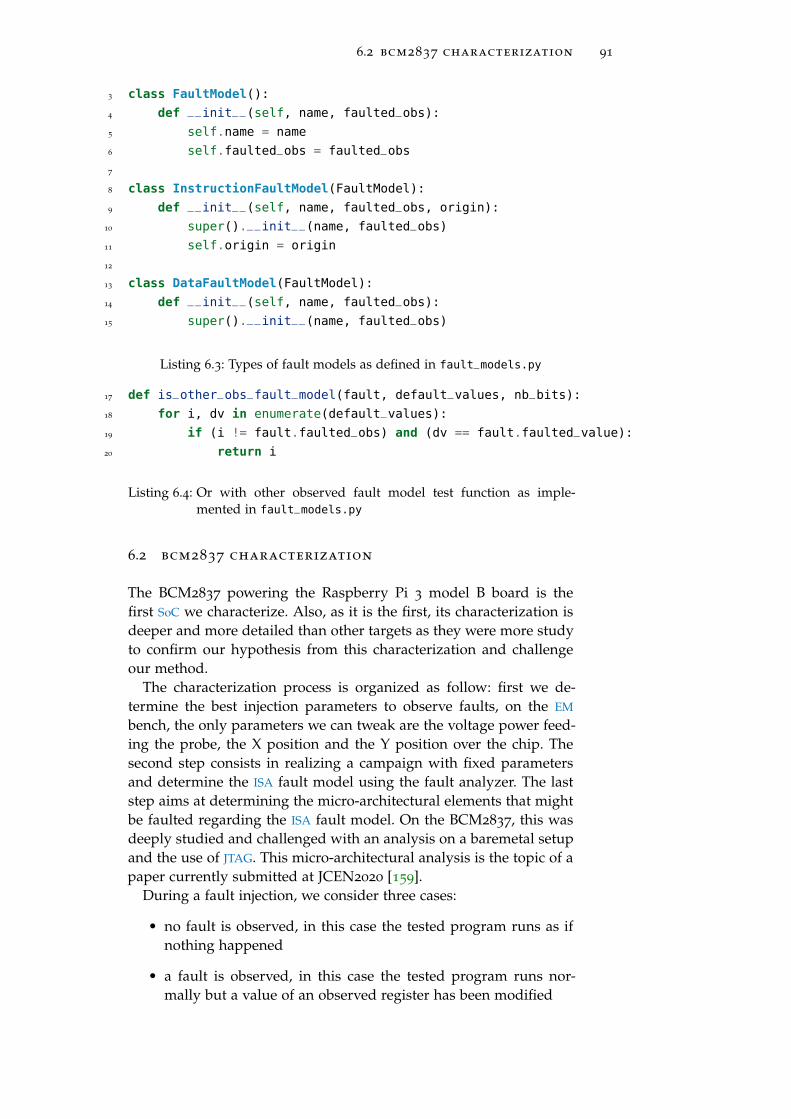
6.2 bcm2837 characterization 91
3 class FaultModel():
4 def __init__(self, name, faulted_obs):
5 self.name = name
6 self.faulted_obs = faulted_obs
7
8 class InstructionFaultModel(FaultModel):
9 def __init__(self, name, faulted_obs, origin):
10 super().__init__(name, faulted_obs)
11 self.origin = origin
12
13 class DataFaultModel(FaultModel):
14 def __init__(self, name, faulted_obs):
15 super().__init__(name, faulted_obs)
Listing 6.3: Types of fault models as defined in fault_models.py
17 def is_other_obs_fault_model(fault, default_values, nb_bits):
18 for i, dv in enumerate(default_values):
19 if (i != fault.faulted_obs) and (dv == fault.faulted_value):
20 return i
Listing 6.4: Or with other observed fault model test function as imple-mented in fault_models.py
6.2 bcm2837 characterization
The BCM2837 powering the Raspberry Pi 3 model B board is thefirst SoC we characterize. Also, as it is the first, its characterization isdeeper and more detailed than other targets as they were more studyto confirm our hypothesis from this characterization and challengeour method.
The characterization process is organized as follow: first we de-termine the best injection parameters to observe faults, on the EM
bench, the only parameters we can tweak are the voltage power feed-ing the probe, the X position and the Y position over the chip. Thesecond step consists in realizing a campaign with fixed parametersand determine the ISA fault model using the fault analyzer. The laststep aims at determining the micro-architectural elements that mightbe faulted regarding the ISA fault model. On the BCM2837, this wasdeeply studied and challenged with an analysis on a baremetal setupand the use of JTAG. This micro-architectural analysis is the topic of apaper currently submitted at JCEN2020 [159].
During a fault injection, we consider three cases:
• no fault is observed, in this case the tested program runs as ifnothing happened
• a fault is observed, in this case the tested program runs nor-mally but a value of an observed register has been modified

92 experimental work
1 class Fault():
2 def __init__(self, faulted_obs, faulted_value):
3 self.faulted_obs = faulted_obs
4 self.faulted_value = faulted_value
Listing 6.5: Fault class as implemented in fault.py
92 instr_fault_models = [
93
94 "name": "Other observed value",
95 "test": is_other_obs_fault_model
96 ,
97
98 "name": "Other observed complementary value",
99 "test": is_other_obs_comp_fault_model
100 ,
Listing 6.6: Two first instruction fault models as implemented in fault_-
models.py
• the device needs a reboot, in this case the fault effect drovethe device in a state where we cannot recover any informationabout the registers and we need to restart it
On the BCM2837, we used two test codes based on the repetition oforr r5,r5 and and r8,r8 instructions as introduced in section 5.3.2.1.
6.2.1 Hot-spots maps
As mentioned above, our first aim is to determine the optimal injec-tion parameters. To do so we realize two experiments. The first oneaims at determining the (X, Y) position of the probe where effectsand faults are obtained. The second one aims at determining the bestvoltage input for obtaining faults.
6.2.1.1 Spatial location
The hot spots maps are presented in figure 51. For this experiment,the chip was divided in a 40× 40 grid and every position was tested30 times leading to 48000 injections in total. The X-axis and Y-axisrepresent the position of the probe over the chip in mm.
The figure 51a displays the positions where reboots were obtained.Two areas are highlight, one on the top right and one on the left. Asmentioned above, the die does not fill the whole package thereforewe can see that the effects are not obtained when the probe is overthe die but over the wire bounding. Also, the area on the left seemsto be very sensitive with almost 50% of reboots.
The figure 51b shows the probe positions where a fault is obtained.They do not perfectly overlay with the positions where reboots whereobtained as they are more concentrated in the bottom right of the

6.2 bcm2837 characterization 93
1413121110987654321Position (mm)
0
1
2
3
4
5
6
7
8
9
10
11
12
13
Position(m
m)
01234567891011121314
Number
ofreboots
per
positions
(a) BCM2837 hot spots leading to re-boots using EM perturbation
1413121110987654321Position (mm)
012345678910111213
Position(m
m)
0
1
2
3
4
Number
offaultsper
positions
(b) BCM2837 hot spots leading tofaults using EM perturbation
Figure 51: Hot spots of the BCM2837 regarding EM perturbation
chip. However, faults seems less probable to obtain as the maximumof faults we could observe for a position is 4 (13%). However, thisprobabilities are not relevant with only 30 test per positions, but thedifference with reboots remains interesting.
Regarding these maps, we decide to fix the probe position to X =
11mm and Y = 5mm for the other experiments.
6.2.1.2 Input voltage
The other injection parameter we want to tweak is the voltage pulseamplitude feeding the probe. For the determination of this value wetested the voltage amplitude between 400V and 600V with a step of10V and we realized 1000 for each value leading to 21000 tests. Realiz-ing injections below 400V does not provoke any effect and injectionsabove 600V leads to an very high number of reboots, which does notinterest us.
This campaign was realized on both experiments (orr r5,r5 andand r8,r8). The results are presented in figure 52.
400 420 440 460 480 500 520 540 560 580 600
0
2
4
6
8
10
12
Power value (V)
Occ
urr
ence
(%)
and r8,r8 (fault)orr r5,r5 (fault)and r8,r8 (reboot)orr r5,r5 (reboot)
Figure 52: Input voltage amplitude effect on BCM2837 during EM perturba-tion

94 experimental work
These results does not highlight a particular behavior of the chipregarding the voltage amplitude. Also, the fault probability seems tobe different regarding the tested program, which is counter intuitive.However, we did not make further researches to understand this phe-nomena and decided to keep sweeping the input voltage from 400V
to 600V .
6.2.2 Analyzer results
After having determined the injections parameters, we realize a cam-paign with the aforementioned parameters. Once the experiments aredone, the fault analyzer presented in section 6.1.3.2 gives some statis-tical information we can use to determine the fault model.
6.2.2.1 Fault probability
One observation from these experiments is that the fault is dependentof the executed instructions. The experiments with a orr are faultedwith a probability around 3% while the experiments with a and arefaulted with a probability around 1%. As mentioned above, this be-havior was not more deeply studied.
6.2.2.2 Faulted values distribution
An interesting information to have is the distribution of the faultedvalues we observed. Indeed, this helps to determine if the fault has atendency to be random or deterministic. The results for both experi-ments are presented in figures 53 and 54.
0x000008e0
0xfefe0000
0xe49de004
0xe28dd00c
0xe12fff1e
0xe92d000e
0xe52de004
0xe24dd008
0xe28d3010
0xe1a02003
0xe59d100c
0xe58d3004
0x00200000
0xfffe0001
0x00000004
0x00000000
0x60000010
0x00100000
0x00000880
0x76ff00000
10
20
30
40
Faulted values
Occ
urr
ence
(%)
Figure 53: and r8,r8 faulted values distribution on BCM2837 using EM per-turbation
These results show that the fault effects are relatively deterministic.Indeed in both experiments, there are values that are outstandinglyrecurrent, i.e. they are observed with a probability above 35%.

6.2 bcm2837 characterization 95
0x000005e1
0x7bb8ddd6
0x3fac1d04
0xd3f8f3b1
0xc3d0c220
0x60000010
0x3ba81d04
0xffb83f05
0xfbf8dff6
0xf3f8fff7
0x72b8ccd6
0x3ba81d05
0xf3f8cef6
0xfbf8df24
0xe3d0c230
0x72b8cdf7
0x3b7b5800
0xc457e2fb
0x000020e1
0x07d84c05
0xfff9fff7
0x00000007
0x00000bc2
0xfeb8eff7
0x77503a08
0x76f51000
0xeeb07f11
0x3b797000
0x0000000b
0x000007e5
0xff707e0a
0x140280230
10
20
30
40
Faulted values
Occ
urr
ence
(%)
Figure 54: orr r5,r5 faulted values distribution on BCM2837 using EM per-turbation
These results give us the information that, despite being probabilis-tic, the fault effect is quite repeatable and therefore we aim at under-standing what is its effect, or at least the most probable effect. Also,the origin of these faulted values will be discussed below while de-termining the fault model.
6.2.2.3 Targeted register
Another interesting information is the probability for a register to befaulted. The results are presented in figure 55.
r0 r1 r2 r3 r4 r5 r6 r7 r8 r90
20
40
60
80
Observed
Fau
ltp
roba
bilit
y(%
)
and r8,r8
orr r5,r5
Figure 55: Probability of observed registers to be faulted for both experi-ments on BCM2837 using EM perturbation
It shows that, in the experiments with the orr r5,r5 instruction,the r5 is faulted in around 87.5% of the cases. In the case of theand r8,r8 instruction, the r8 register is faulted in around 65.5% ofthe cases. This suggests that the most faulted register is directly linkedwith the executed instruction and that the fault effect is highly repeat-able.

96 experimental work
Moreover, in any experiment, the r0 register is always significantlyfaulted with a probability varying between 10% and 25% of the cases.
Other registers might be faulted but with a probability alwayslower than 2%.
6.2.2.4 Fault model
The fault analyzer presented above able to heuristically determinehow the observed faulted values are obtained. As explained, it aimsas determining simple relations between the faulted values and theinitial values of the registers. The figure 56 introduces the results ofsuch analysis on the experiments made on the BCM2837.
Fault modelunknown
Bitreset
Other obsvalue
And withother obs
Or withother obs
Other obsvalue afterexecution
Or withtwo other
obs
0
10
20
30
40
Fault model
Occ
urr
ence
(%)
and r8,r8
orr r5,r5
Figure 56: Probability of observing the different fault models for both exper-iments on BCM2837 using EM perturbation
As the analysis is heuristically done, there are some cases in whichthe fault analyzer could not determine a fault model. In this case thefault can be considered completely random. However in other cases,a simple relation between the values could be determine. It is inter-esting to note that regarding the experiments, the most probable faultmodel is either “And with other obs” (in the and r8,r8 experiment)or “Or with other obs” (in the orr r5,r5 experiment). This suggeststhat the fault model is directly linked to the executed instruction.
Based on these results, and regarding the method presented in sec-tion 5.3.1 with the figure 35, we want to determine if the fault targetsthe data (i.e. the registers) or the instructions. Actually, the fault tar-gets both, but with different probabilities, our aim is to determinatehow these effects behave.
6.2.2.5 Bit reset fault model
One observed fault model is a complete reset of the faulted register.This happen only during the and r8,r8 experiment with a relativelylow (3.27%) probability. As mentioned above, it can be the registerforced to 0 or a XOR between a register and itself. However, due to itslow probability, we do not focus more on this fault model.

6.2 bcm2837 characterization 97
6.2.2.6 Instruction loading and shift
In some cases, the faulted value is computed from the executed in-struction such as in equation (34).
vf = (i rotl 8)∧ 0xfff (34)
with vf is the faulted value, i the executed instruction, and rotl thebit rotation to the left operation. This fault is observed with variousinstructions.
This fault model is complicated. As it fetches an instruction into aregister, we can suppose that there is a load from the memory withthe PC as base address register such as ldr r0, PC. This way, thevalue targeted by the address stored in the PC register will be loadedin r0. However, the left shift mechanism is difficult to explain. Thereexists a rolling mechanism on the operand in the ARM instructionset, for instance ldr r0, [lsl PC, #8], but it does not fully explainour observations. This fault model appears between 20% and 35%of the cases for each experiment. This is a high probability regard-ing other fault models probability, however, as it is complicated, it iscomplicated to exploit it.
6.2.2.7 Instruction corruption
The other observed fault model is an instruction corruption.Based on the figure 56, the most important fault model for the
orr r5,r5 instruction is the “Or with other obs”. Regarding the exe-cuted instruction, this fault model corresponds to modify the operandsor the destination of the instruction. With this fault model, the faultedregister is r5 in 100% of the cases, meaning that the destination of theinstruction is not modified. Therefore, the fault modifies an operandused by the instruction. To determine which effect the fault has onthe instruction, we simply determine the instruction that explain ourobservations. The result is given in table 4.
Faulted instruction Occurrence (%)
orr r5,r1 92.54%
orr r5,r0 6.14%
orr r5,r7 1.32%
Table 4: orr r5,r5 corruptions regarding the “Or with other obs” faultmodel
This table shows that the fault has a high probability to force anoperand to r1. In some cases, the operand is forced to r0 or r7.
Regarding the and r8,r8 instruction experiment, the same kind ofcorruption is observed, it corresponds to the “And with other obs”fault model. Moreover, in this case there is only one corruption whichhappen in 100% of the cases and the corresponding faulted instruc-tion is and r8,r0. In this case, the operand is forced to r0 insteadof r1 but the behavior remains the same. However, the reason why

98 experimental work
we observe r0 or r1 is not identified, we suppose it comes from theinitial register involved in the instruction but we did not confirm thishypothesis. We can say that the fault force the operand to low ham-ming weight values, which match the force to zero behavior of the EM
injection medium.While looking at the orr r5,r5 instruction experiment we also ob-
serve the “Or with two other obs” fault model. It is similar to theprevious one but, in this case, the two operands are modified. Theresults corresponding to these corruption are presented in table 5.
Faulted instruction Occurrence (%)
orr r5,r4,r1 51.86%
orr r5,r0,r1 48.14%
Table 5: orr r5,r5 corruptions regarding the “Or with two other obs” faultmodel
This table shows that one of the operand is always forced to r1
while the destination remains unchanged and the other operand iseither r4 or r0.
The last behavior we observed correspond to the “Other obs value”in this fault model the operands are modified but also the operationcode. In this case, it corresponds to a mov operation. Considering thisoperation, two information are important, the origin of the value andits destination. In the orr r5,r5 experiment, the results are presentedin table 6.
Faulted instruction Occurrence (%)
mov r5, r0 46.48%
mov r5, r4 30.99%
mov r5, r1 21.12%
mov r0, r5 1.41%
Table 6: orr r5,r5 corruptions regarding the “Other obs value” fault model
These results show that the registers r0, r1 and r4 already involvedin the other fault models remains the ones the fault forces to use andthey all are low hamming weight registers. However, the r1 registeris not the more probable in this case. We did not find any explanationfor the higher presence of r0 in this case.
Regarding the and r8,r8 experiment, the results are presented intable 7.
Faulted instruction Occurrence (%)
mov r8, r0 72.73%
mov r0, r8 18.18%
mov r4, r0 9.09%
Table 7: and r8,r8 corruptions regarding the “Other obs value” fault model

6.2 bcm2837 characterization 99
These results show some similarities with the previous ones. Thefault force the registers to low hamming weight ones (r0 and r4).
Regarding these experiments, we can conclude that our fault mostof the time corrupts the operands of the executed instruction andforce them to low hamming weight values. However, sometimes it in-fers a register corruption or a modification of the instruction opcode.This correspond to the ISA fault model however, as mentioned above,we are interested in the micro-architectural fault model to determineif these behaviors come from some SoC specificities and to be able tobuild efficient countermeasures against them.
6.2.2.8 Number of faulted instructions.
When working with modern CPUs with high frequencies (> 1GHz),one important fault parameter is the spreading. We determined thefault affects instructions but we cannot determine how many instruc-tions are actually faulted.
Regarding the BCM2837 CPU frequency (1.2GHz) and the injectorfirst peak duration (3.25× 10⁻⁹ s), we can suppose that a fault per-turbs around 4 (1.2 × 109 · 3.25 × 10−9 = 3.9) instructions. To con-firm this hypothesis we decided to fault a test program composedof the repetition of the mov rX,rX with X ∈ [[0, 9]]. We observed thatin 84.34% of the cases, the fault corrupts the instruction, the faultedinstruction becoming mov rX,rY with (X, Y) ∈ [[0, 9]]2.
Faulting such program gave us the information that, on average,the fault affects 1.45 instructions. As this result is different from theexpected one, it can be explained by the fact that the CPU does notrun at maximum speed all the time.
Regarding this result, we can focus our analysis on the corruptionof one or two instructions.
6.2.2.9 Correspondence between the fault model and the instruction encod-ing
Before doing the micro-architectural analysis, it is interesting to con-front the instruction corruption we observe regarding how instruc-tions are encoded. The figure 57 presents the encoding of the dataprocessing instructions in the ARM architecture.
012345678910111213141516171819202122232425262728293031
If immediate value bit (25) is set to 0
Second operandFirstoperand
Destinationregister
OpCode
012345678910111213141516171819202122232425262728293031
If immediate value bit (25) is set to 1
Firstoperand
Destinationregister
OpCode Immediate value
Figure 57: Data processing instruction encoding on ARM

100 experimental work
This figure shows on which bits the information composing a dataprocessing instruction (operands, opcode, destination) are encoded.As we know the initial instruction we execute, we are able to deter-mine which bits are faulted by our perturbation.
As we observe a fault on the operands or the opcode, we know thatour fault is equivalent to modify the bits 0 to 3 (second operand), thebits 16 to 19 (first operand) or the bits 21 to 24 (opcode).
As we mentioned above, the fault seems to set bits to 0 as we ob-serve low hamming weight faulted values. The only counter-exampleis when we observed a corruption of the second operand from r5
(0b0101) to r7 (0b0111). Also, we observed a corruption of the op-code, and by checking the binary values of the original and the faultsopcodes presented in table 8, we concluded that they are not forcedto low hamming weight values.
Original opcode Faulted opcode
orr (0b1100) mov (0b1101)
and (0b0000) mov (0b1101)
Table 8: Binary values of the observed opcodes.
This table shows that the faulted opcode always have a higher ham-ming weight than the original instruction. This observation lead totwo conclusions. The first one is that the opcode and the operandsare not faulted in the same way, this explain the probability differ-ence between faulting an opcode and faulting an operand. The otherone is that considering the way instructions are encoded to determinethe fault model is not relevant because the fault does not affect theirencoding but another micro-architectural mechanism of the core.
This second conclusion seems to be the most relevant for us, es-pecially due to the fact we observed similar faults on another archi-tecture (x86 presented in section 6.4) because a different architecturemeans a different instruction encoding.
6.2.3 Micro-architectural analysis using a test program
Now that we have determined the ISA fault model, we want to de-termine which micro-architectural blocks are faulted and can explainour observations. To do so, we realize two experiments based on testprograms specifically adapted to our previous observations.
6.2.3.1 Fault during instruction fetch determination
We saw that the fault usually perturbs the instruction second operand.However, regarding the instruction encoding presented in figure 57,the second operand can either be a register or an immediate value. Aswe want to determine which part of the micro-architecture is faultedwe want to test our injection setup on program working with immedi-ate value rather than registers. Indeed, if the fault is the same in bothcases, it means that it targets a part of the core which does not distin-

6.2 bcm2837 characterization 101
guish registers from immediate value, in other words, every blocksbefore the decoding stage of the pipeline. If the fault is only observeon the registers, it means that it targets a block which specificallyworks differently regarding if we use registers or immediate values.The only block doing so is the execute stage of the pipeline.
The main issue is that our test codes are not suitable for testing themanipulation of immediate values as they would overwrite a fault.Therefore, we had to realize a different kind of test program pre-sented in listing 6.7.
cmp r3, #255
bne fault
b nofault
fault: mov r9, #170
b end
nofault: mov r9, #85
end: nop
Listing 6.7: BCM2837 immediate value test program
This program realizes a comparison between the register r3 andthe value 0xff. If they are equal, the processor will pass the bne in-struction and then branch to the nofault tag. Then the register r9
is loaded with the value 0x55 and the program terminate. If r3 and0xff are not equal, then the program will branch to the fault tag. r9will be loaded with 0xaa, and then the processor will branch to theend tag and terminates.
The attack aims to fault the cmp r3, #255 instruction. As r3 is ini-tialized with the value 0xff, the first scenario must happen. How-ever, according to our fault model, we should modify the secondoperand (which is an immediate value in this case) and force it to0. Therefore, the processor will follow the second scenario. If it hap-pens, we achieved to modify the control flow of the program with ourElectroMagnetic Fault Injection (EMFI) and actually faulted an imme-diate value. The observation of r9 gives us this information.
table 9 gives the results for this experiment. This table shows thatin more than 90% of the cases we effectively fault the immediatevalue. This experiment confirms that the fault model we determinedis portable on other instructions, in particular, instruction using im-mediate values.
Fault Fault (r9 = 0xaa) r9 = 0xfffcb924 Unknown
Appearance rate 94% 4% 2%
Table 9: Fault distribution on cmp test code
It is interesting to note that the probability of modifying the con-trol flow is very high. Greater than 90%. This high probability can beexplained with the fact that many faults on the cmp r3, #255 instruc-tion can lead to the second scenario, such as first operand corruption

102 experimental work
or opcode corruption. However, regarding our previous experiment,we are confident the consequence of corrupting the second operand.
Therefore, this observation on corrupting an immediate value givessome information on the effect of the fault in the pipeline. Indeed,pipelines are built on three main functions: the fetch which reads theinstruction and compute the PC, the decode which decodes the instruc-tion and set the flags in the pipeline and the execute which executesthe decoded instruction and stores the result.
From these functions, only execute behaves differently if the secondoperand is an immediate value or a register. Regarding the electronicway, the multiplexer of the second operand in the ALU select eitherthe immediate value or a register.
MUX1
immediate value bit(instruction bit 25)
ALU
opcode(instruction bits 21 to 24)
MUX2
Registers
....
first operand (instruction bits 16 to 19)
....
immediate value second operand (instruction bits 0 to 7)ope2
ope1
register second operand (instruction bits 0 to 3)
....
destination(instruction bits
12 to 15)
Figure 58: Pipeline execute stage architecture with ARM instruction (fig-ure 57) corresponding bits
Figure 58 shows the big map of the pipeline execute stage architec-ture. Multiplexers are used to feed the ALU with the operands. Theflags and value used are the same as the one exposed in Figure 57
and come from the decode stage. The multiplexer MUX1 is driven bythe immediate value bit.
Regarding our fault model, second operand corruption either it isa register or an immediate value, and based on the figure 58, we cansee that it matches with corrupting the MUX2 selector signal (modify-ing the register second operand) or corrupting the MUX1 down input(modifying the used immediate value). In both cases, this matcheswith corrupting the lower bits of the instructions. Therefore, we canconclude that these bits are corrupted before they are decoded andused in the execute stage. This means that the fault occurs before theinstruction reaches the decode stage, in other words, the fault happenduring the instruction fetch and might target any micro-architecturalblock from the external memory to the fetch stage, including thecaches.
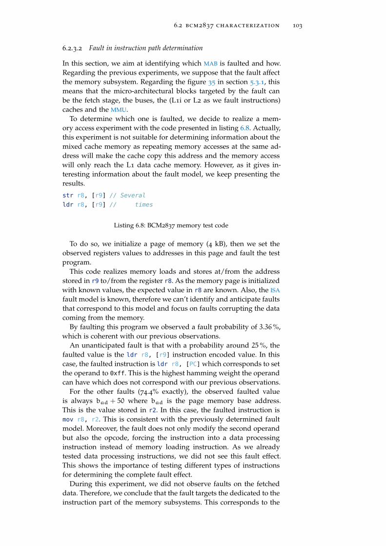
6.2 bcm2837 characterization 103
6.2.3.2 Fault in instruction path determination
In this section, we aim at identifying which MAB is faulted and how.Regarding the previous experiments, we suppose that the fault affectthe memory subsystem. Regarding the figure 35 in section 5.3.1, thismeans that the micro-architectural blocks targeted by the fault canbe the fetch stage, the buses, the (L1i or L2 as we fault instructions)caches and the MMU.
To determine which one is faulted, we decide to realize a mem-ory access experiment with the code presented in listing 6.8. Actually,this experiment is not suitable for determining information about themixed cache memory as repeating memory accesses at the same ad-dress will make the cache copy this address and the memory accesswill only reach the L1 data cache memory. However, as it gives in-teresting information about the fault model, we keep presenting theresults.
str r8, [r9] // Several
ldr r8, [r9] // times
Listing 6.8: BCM2837 memory test code
To do so, we initialize a page of memory (4 kB), then we set theobserved registers values to addresses in this page and fault the testprogram.
This code realizes memory loads and stores at/from the addressstored in r9 to/from the register r8. As the memory page is initializedwith known values, the expected value in r8 are known. Also, the ISA
fault model is known, therefore we can’t identify and anticipate faultsthat correspond to this model and focus on faults corrupting the datacoming from the memory.
By faulting this program we observed a fault probability of 3.36%,which is coherent with our previous observations.
An unanticipated fault is that with a probability around 25%, thefaulted value is the ldr r8, [r9] instruction encoded value. In thiscase, the faulted instruction is ldr r8, [PC] which corresponds to setthe operand to 0xff. This is the highest hamming weight the operandcan have which does not correspond with our previous observations.
For the other faults (74.4% exactly), the observed faulted valueis always bad + 50 where bad is the page memory base address.This is the value stored in r2. In this case, the faulted instruction ismov r8, r2. This is consistent with the previously determined faultmodel. Moreover, the fault does not only modify the second operandbut also the opcode, forcing the instruction into a data processinginstruction instead of memory loading instruction. As we alreadytested data processing instructions, we did not see this fault effect.This shows the importance of testing different types of instructionsfor determining the complete fault effect.
During this experiment, we did not observe faults on the fetcheddata. Therefore, we conclude that the fault targets the dedicated to theinstruction part of the memory subsystems. This corresponds to the
104 experimental work
L1 instruction cache, its connected buses, the MMU and the fetch MAB.However, using only test programs, we cannot more deeply deter-mine which MAB is faulted. Therefore, we decide to use a baremetalsetup with a JTAG to realize deeper characterization as introducedin [159].
6.2.4 Micro-architectural analysis on a baremetal setup with JTAG
This section focus on determining the fault model at the micro-architecturallevel on the BCM2837 using a baremetal setup (i.e. no OS) and a JTAG
connection. This method was only be done on the BCM2837 becauseit is very time consuming. Indeed, unlike the method presented insection 5.3, this method consists in faulting a program, wait for afault, stall the program when a fault appear and manually debug themicro-architectural elements such as the cache memory or the MMU.This debug step is time consuming, requires an expert each time andtherefore cannot be repeated an important amount of time to confrontthe observation with a statistical analysis.
However, this characterization gives information about what canhappen while faulting the BCM2837 and we can suppose that thefault we observe are the more likely to happen. Moreover, this charac-terization work was done within a collaboration with the LHS (Labo-ratoire de Haute Sécurité) of the INRIA of Rennes. This team devel-oped the baremetal setup and realized the characterized experiments,however, their injection setup is not the same as ours but, as we fo-cus on characterizing the faults and not how to achieve them, wedecided to abstract this difference during the analysis. The reason isthat, during this collaboration, we focused on comparing the faultmodel observed on the Linux and the baremetal setups.
6.2.4.1 Baremetal and Linux setup behavior differences against EM faultinjection
This characterization did not highlight a different behavior betweenthe baremetal and the Linux setup regarding the fault models. With-out realizing a deep characterization like above, we simply presentthe observed fault model while faulting a test program repeating theorr r3,r3 instruction in figure 59.
This result shows that the most observed fault model is the “Orwith other obs” with a probability of 86.46%. This perfectly matchour observations on the Linux setup and we therefore can concludethat the Linux OS has no impact on the observed fault model.
6.2.4.2 Target setup for micro-architectural characterization
As we aim at characterizing the fault effect at the micro-architecturallevel, the test program presented in section 5.3.2.1 cannot help us.Therefore, we decide to fault a more complete program presented inlisting 6.9.

6.2 bcm2837 characterization 105
Fault modelunknown
Bit set Other obsvalue
Or withother obs
Or withtwo other
obs
0
20
40
60
80
Fault model
Occ
urr
ence
(%)
Figure 59: Probability of observing the different fault models for orr r3,r3
experiment on BCM2837 with a baremetal setup using EM pertur-bation
trigger_up();
//wait to compensate bench latency
wait_us(1);
invalidate_icache();
for(int i = 0; i<50; i++)
for(int j = 0; j<50; j++)
cnt++;
trigger_down();
Listing 6.9: BCM2837 baremetal test program
This test program is composed of two intricate loops. As we aim atverifying that we fault the instruction cache, it is invalidated beforestarting the loops, therefore, it is possible to precisely target the mo-ment the instructions are fetched from the memory and loaded in theinstruction cache.
Actually, by faulting at different moments of the program execu-tion we are able to fault different micro-architectural elements: the L1
instruction cache, the MMU and the L2 mixed cache.
6.2.4.3 Fault on the instruction cache
A fault occurs when the cnt variable value at the end of the programis not equalled to 2500. Since a fault is detected, we use the JTAG tore-execute our loop for, in the listing 6.9, by directly setting the PC
value at the start of the loops. Executing instruction by instruction,we monitor the expected side effects. This execution is done withoutfault injection. Each instructions was well-executed except for the add
instruction at address 0x48a08 on listing 6.10.

106 experimental work
...
0x48a04: 0xb94017a0 ldr x0, [x29,#20]
0x48a08: 0x11000400 add x0, x0, #0x1
0x48a0c: 0xb90017a0 str x0, [x29,#20]
0x48a10: 0xb9401ba0 ldr x0, [x29,#24]
0x48a14: 0x11000400 add x0, x0, #0x1
0x48a18: 0xb9001ba0 str x0, [x29,#24]
0x48a1c: 0xb9401ba0 ldr x0, [x29,#24]
0x48a20: 0x7100c41f cmp x0, #0x31
0x48a24: 0x54ffff0d b.le 48a04 <loop+0x48>
...
Listing 6.10: BCM2837 assembly code of the loop test program
By monitoring the x0 register before and after the cnt increment-ing instruction, we observe that the value is kept unchanged: the in-crement is not executed. Since the fault is still present after the EMinjection, we can conclude that a wrong instruction value is stored inthe L1 instruction cache. We confirm this fault model by invalidatingthe instruction cache using the ic iallu instruction. By re-executingour application, the fault has disappeared.
We can infer that the injected fault has affected a part of the in-struction cache. However, it is impossible to access (read) the newincremented value. Since the fault happens during the cache filling,we can suppose that the memory transfer had been altered. More-over, the ISA fault model determined above can explain the absenceof increment in the case the instruction add x0, x0, #1 is forced toadd x0, x0, #0.
This confirms that the instruction cache can be faulted in a way thatmatches the fault model we determined above.
6.2.4.4 Fault on the MMU
During the experiments on the baremetal setup, we observed thatthe MMU can be faulted. As presented in section 4.4.1.2 the MMU relyon PTEs to operate. These PTEs are stored in a Translation LookasideBuffer (TLB) which is basically a cache for PTEs. In our baremetal setup,the PTEs are configured to realize an identity mapping, i.e. the virtualaddress used by the CPU is the same as the physical address used bythe RAM.
To reconstruct the memory mapping, we use a pair of instructionscomputing the physical address (and the corresponding metadata)for a given virtual one and a script has been designed to extract thememory mapping.
With this method, we compare the memory mappings with (list-ing 6.12) and without (listing 6.11) a fault.
Three different effects can be observed depending on the page:
1. Pages are correct with an identity mapping up to 0x70000. Re-markably these are all the pages used to map our applicationin memory. Therefore, a hypothesis is that the corresponding

6.2 bcm2837 characterization 107
VA -> PA
0x0 -> 0x0 0x80000 -> 0x80000
0x10000 -> 0x10000 0x90000 -> 0x90000
0x20000 -> 0x20000 0xa0000 -> 0xa0000
0x30000 -> 0x30000 0xb0000 -> 0xb0000
0x40000 -> 0x40000 0xc0000 -> 0xc0000
0x50000 -> 0x50000 0xd0000 -> 0xd0000
0x60000 -> 0x60000 0xe0000 -> 0xe0000
0x70000 -> 0x70000 0xf0000 -> 0xf0000
Listing 6.11: BCM2837 with baremetal setup with correct identity memorymapping
VA -> PA
0x0 -> 0x0 0x80000 -> 0x0
0x10000 -> 0x10000 0x90000 -> 0x0
0x20000 -> 0x20000 0xa0000 -> 0x0
0x30000 -> 0x30000 0xb0000 -> 0x0
0x40000 -> 0x40000 0xc0000 -> 0x80000
0x50000 -> 0x50000 0xd0000 -> 0x90000
0x60000 -> 0x60000 0xe0000 -> 0xa0000
0x70000 -> 0x70000 0xf0000 -> 0xb0000
Listing 6.12: BCM2837 with baremetal setup with faulted memory mapping
translations are present in caches and are not impacted by thefault.
2. Pages are incorrectly mapped to 0x0. A read at 0x80000 reads,with success, physical memory at 0x0.
3. Pages are shifted. A read at 0xc0000 gives the physical memoryvalue at 0x80000.
If we invalidate the TLB after a fault, nothing changes: the mappingstills modified. We conclude that the fault does not affect the cachemechanism of address translation (at least what can be invalidated bysoftware) but directly the MMU configuration.
This fault model is very powerful as it able to break the memorypartitioning. However, we did not observed it at the ISA level as itsimpact at this layer corresponds to fetch the wrong instruction or thewrong data. Considering that we do not initialize the RAM to knownvalue, the fault is likely to fetch a random data, this can explain whythe analyzer could not determine a fault model for all faults.
6.2.5 Conclusion on the BCM2837 characterization
In this section we realized the characterization of faults on the BCM2837
CPU. We determined that the fault mainly modify the instructionoperands by targeting the memory cache. We also determine that theMMU and the mixed cache can be affected.
The memory is known to be faulted on SE but these results able usto conclude that the large integration of cache memory make modernCPUs sensitive to faults. The next experiments will able to confirm this

108 experimental work
observation on a more up-to-date device using a laser and even onanother architecture using EM perturbation.
However, because it is time consuming, no micro-architectural de-bugging has been done on the following targets. We only focus oncomparing the results at the ISA level and considering that if the ISA
observations are the same, therefore, the micro-architectural behavioris the same.
6.3 bcm2711b0 characterization
The BCM2711b0 was characterized while perturbed using a laser. Theanalysis process is the same as the one presented in above with theBCM2837. As we could only access a laser bench during a restrictedduration, we only tested the program based on the orr r5,r5 instruc-tions. However, this timing constraints helped to confirm the rele-vance of having a well defined method we could use to analyze andcharacterize our device.
6.3.1 Hot-spots maps
As mentioned above, our laser injection setup has its parameters fixed.Therefore, the only injection parameter we have to drive is the posi-tion of the laser spot over the chip. However, as the laser spot isaround 1µm and that the chip surface is around 42mm2, this step isvery time consuming. Therefore, to reduce this step, we only focusedon the cores. The results are presented in figure 60.
0 1 2 3 4 5 6 7X position (mm)
0
1
2
3
4
5
6
Yposition(m
m)
0
1
Number
offaultsper
position
Figure 60: BCM2711b0 hot spots leading to faults using laser perturbation
It is important to note that the dot size on the figure does not matchthe laser spot size. Also, as these experiments were done with ourbench manager, we do not have results about the reboots of the target.
The figure 60 shows that the cores are sensitive to laser fault injec-tion and, in particular, the cache memory. This is a first interesting

6.3 bcm2711b0 characterization 109
information as we determined on the BCM2837 CPU that the cacheis faulted. However, as we did not have much time to realize theexperiments, we decided to analyze the results of the cartographyexperiment, this might be imprecise as we do not target a specificlocation where we observed an interesting behavior but it will givesinformation about the general behavior of the device against laserfault injection.
6.3.2 Analyzer results
The analyzer gives a statistical analysis of the faulted device. How-ever, as we do not fault the same position, the probabilities must becarefully considered as if the spot was fixed at a specific location, theprobabilities might be different. In particular, the fault probability isnot relevant as we test different positions for the laser spot.
Despite these issues, we propose to realize the same analysis asdone on the BCM2837, abstracting the fact that the experiment wasactually a cartography.
6.3.2.1 Faulted values distribution
As mentioned above, looking at the faulted values distribution helpsus to determine if the fault effect is consistent or very variable. Theresults for the BCM2711b0 are presented in figure 54.
0x00000000
0xffbe0040
0x60000010
0xffff0022
0xffff0021
0xfeff0100
0xfffd0002
0x01010101
0xffff0030
0xffdf0020
0xffff0060
0xffff00a0
0x00000010
0xffffffff
0xb6f41d90
0x00aea150
0xb6e607b8
0x000005e8
0xb6f3fb1c
0xb6f3f6d8
0x00000007
0x00000001
0x07fe0001
0xfffd0020
0xffff0220
0xfffb0004
0x0000000b0
10
20
30
40
Values
Pro
babi
lity
ofap
pea
ranc
e(%
)
Figure 61: orr r5,r5 faulted values distribution on BCM2711b0 using laserperturbation
These results shows that, despite we are doing a cartography, somevalues are very likely (between 10% to 40%) to appear. This suggeststhat the device is perturbed in a consistent way.
6.3.2.2 Targeted register
As with the BCM2837, another interesting information is the distribu-tion of the faulted register. This result for the BCM2711b0 is given infigure 62.

110 experimental work
r0 r1 r2 r3 r4 r5 r6 r7 r8 r90
20
40
60
Observed registers
Fau
ltp
roba
bilit
y(%
)
Figure 62: Probability of observed registers to be faulted for orr r5,r5 ex-periment on BCM2711b0 using laser perturbation
This result shows that the r5 register is faulted in more than 65%of the cases. This actually match our observation while perturbingthe BCM2837 using EM perturbations. This strongly suggests thatthe faulted register is linked with the executed instruction, whichis orr r5,r5 in this case. Moreover, we can suppose that the reasonwe have the same observation on both targets is the same, i.e. that thefault model on both targets is the same.
This hypothesis is very interesting as, if it is actually the case,this means the fault model is independent from the used injectionmedium.
6.3.2.3 Fault model
The fault model distribution observed on the BCM2711b0 is presentedin figure 63.
Unknown Bit reset Bit set Or withother obs
Other obsvalue
Xor withother obs
0
10
20
30
40
Fault models
Occ
urr
ence
(%)
Figure 63: Probability of observing the different fault models for orr r5,r5
experiment on BCM2711b0 using laser perturbation

6.3 bcm2711b0 characterization 111
A major issue one can easily identify is that the analyzer couldnot determine the fault model in around 50% of the observed fault.This is quite important compared with the other experiments. How-ever, some of them have important probability of appearance and inparticular the “Or with other obs” fault model. Also, one must keepin mind that the experiment is actually a cartography and that com-plex behavior might come from the fact that we are testing variouspositions.
It is interesting to note the presence of the “Or with other obs” faultmodel as it correspond to the fault model observed on the BCM2837
executing the orr r5,r5 instruction presented in figure 56 in sec-tion 6.4.2.4. This suggests that, on some positions, the BCM2837 andthe BCM2711b0 are perturbed in similar way independently of theused injection medium.
Actually, some fault models are in common for both target, the onlynew ones are the “Bit set” which force all bits of the register to 1 andthe “Xor with other observed”.
6.3.2.4 Maps per fault model
An interesting information is to analyze the probe location regardingthe fault model. Considering the observed fault models, the corre-sponding maps are presented in figures 64 and 65.
These figures show where the laser spot was located when we ob-served the different fault models. An interesting observation is thatsome fault models are specific to a determined location such as the“Bit set”, “Bit reset” and “Xor with other obs” fault models. For theother fault models, despite they are located at several positions, theydo not really overlap. This suggests that the fault models are due tothe targeted element of the die. Moreover, knowing that they are in-dependent makes our analysis relevant despite we do not analyze fixthe laser spot at a specific location.
6.3.2.5 Register corruption
The fault model distribution suggest that some register corruptionhappened. A register bit reset and a register bit set. Despite they ap-pear with a very low probability (less than 0.5%) they are present.It could be interesting to fix the laser spot to the position they wereobserve to determine if it is consistent.
6.3.2.6 Instruction corruption
Regarding instruction corruption, the analysis gives interesting infor-mation. Indeed, the three remaining fault models “Or with other obs”,“Other obs value” and “Xor with other obs” correspond to instructioncorruption. Moreover, they match the instruction fault model we al-ready observed on the BCM2837 in section 6.2.2.7.
It is interesting to determine in which way the instruction is cor-rupted and if it matches with our observations on the BCM2837.
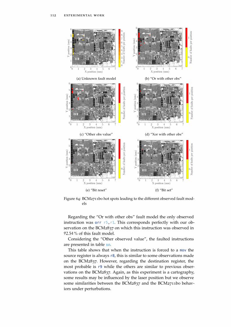
112 experimental work
0 1 2 3 4 5 6 7X position (mm)
0
1
2
3
4
5
6
Yposition(m
m)
0
1
2
3
4
5
6
7
8
9
Number
offaultsper
position
(a) Unknown fault model
0 1 2 3 4 5 6 7X position (mm)
0
1
2
3
4
5
6
Yposition(m
m)
0
1
Number
offaultsper
position
(b) “Or with other obs”
0 1 2 3 4 5 6 7X position (mm)
0
1
2
3
4
5
6
Yposition(m
m)
0
1
Number
offaultsper
position
(c) “Other obs value”
0 1 2 3 4 5 6 7X position (mm)
0
1
2
3
4
5
6
Yposition(m
m)
0
1
Number
offaultsper
position
(d) “Xor with other obs”
0 1 2 3 4 5 6 7X position (mm)
0
1
2
3
4
5
6
Yposition(m
m)
0
1
Number
offaultsper
position
(e) “Bit reset”
0 1 2 3 4 5 6 7X position (mm)
0
1
2
3
4
5
6
Yposition(m
m)
0
1
Number
offaultsper
position
(f) “Bit set”
Figure 64: BCM2711b0 hot spots leading to the different observed fault mod-els
Regarding the “Or with other obs” fault model the only observedinstruction was orr r5,r1. This corresponds perfectly with our ob-servation on the BCM2837 on which this instruction was observed in92.54% of this fault model.
Considering the “Other observed value”, the faulted instructionsare presented in table 10.
This table shows that when the instruction is forced to a mov thesource register is always r8, this is similar to some observations madeon the BCM2837. However, regarding the destination register, themost probable is r9 while the others are similar to previous obser-vations on the BCM2837. Again, as this experiment is a cartography,some results may be influenced by the laser position but we observesome similarities between the BCM2837 and the BCM2711b0 behav-iors under perturbations.
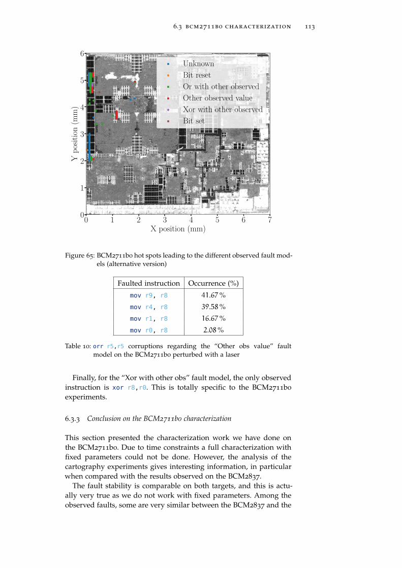
6.3 bcm2711b0 characterization 113
0 1 2 3 4 5 6 7X position (mm)
0
1
2
3
4
5
6
Yposition(m
m)
Unknown
Bit reset
Or with other observed
Other observed value
Xor with other observed
Bit set
Figure 65: BCM2711b0 hot spots leading to the different observed fault mod-els (alternative version)
Faulted instruction Occurrence (%)
mov r9, r8 41.67%
mov r4, r8 39.58%
mov r1, r8 16.67%
mov r0, r8 2.08%
Table 10: orr r5,r5 corruptions regarding the “Other obs value” faultmodel on the BCM2711b0 perturbed with a laser
Finally, for the “Xor with other obs” fault model, the only observedinstruction is xor r8,r0. This is totally specific to the BCM2711b0
experiments.
6.3.3 Conclusion on the BCM2711b0 characterization
This section presented the characterization work we have done onthe BCM2711b0. Due to time constraints a full characterization withfixed parameters could not be done. However, the analysis of thecartography experiments gives interesting information, in particularwhen compared with the results observed on the BCM2837.
The fault stability is comparable on both targets, and this is actu-ally very true as we do not work with fixed parameters. Among theobserved faults, some are very similar between the BCM2837 and the

114 experimental work
BCM2711b0, and in particular the instruction corruption which cor-rupt the instruction operand in the same way on both targets.
As we cannot really conclude that the fault behave in the exactsame way on both targets, this similarity strongly suggests that thefault model is not really depending of the fault injection medium butthe targeted micro-architectural element. Indeed, despite we do notrealize a micro-architectural characterization on the BCM2711b0, thelaser precision able us to confirm that most of the faults we observedare obtain while targeting the cache memory. This cache memory isthe element we identified as the perturbed one on the BCM2837.
Therefore, we conclude that the fault model we observe comes fromthe cache misbehavior on both targets and that these cache react inthe same way to EM and laser perturbations.
6.4 intel core i3 characterization
The Intel Core i3-6100T is the last target we characterize and we usedEM perturbation against it. This target appeared to be harder to faultthan the previous target. This difference was not investigated andmight be due to the manufacturing technology or the architecture ofthe device.
For this target the two tested programs were based on the repeti-tion of the mov rbx,rbx and orr rbx,rbx instructions. To be compli-ant with the Intel nomenclature, the register are named after the x86
specification. However, it does not change anything about the charac-terization method.
6.4.1 Hot-spots maps
As with the previous target, the first characterization step consists indetermining the injection parameter we want to use. This step wasvery time consuming on the Intel Core i3 because it is harder to faultthan the other targets.
6.4.1.1 Spatial location
The first parameter we worked on is the spatial position of the probeover the target. As the Intel Core i3 is covered with a metal package,we had to remove it to use EM perturbations. Doing so, we directlyaccess the die of the chip. This die is visible on figure 66 and wasdivided in a 20× 40 grid, each position was tested 30 times leadingto 24000 operations.
As mentioned, faulting the Intel Core i3 is harder than the previ-ous target, the consequence is that the fault map is not relevant todetermine any interesting positions. However, by using an importantinput power, we were able to observe areas leading to reboots. Thisresult is presented in figure 66.
This figure shows four sensitive areas for the Intel Core i3. Despitewe do not know the layout of the die, we know that this target em-beds two cores. These areas might therefore match these cores, the
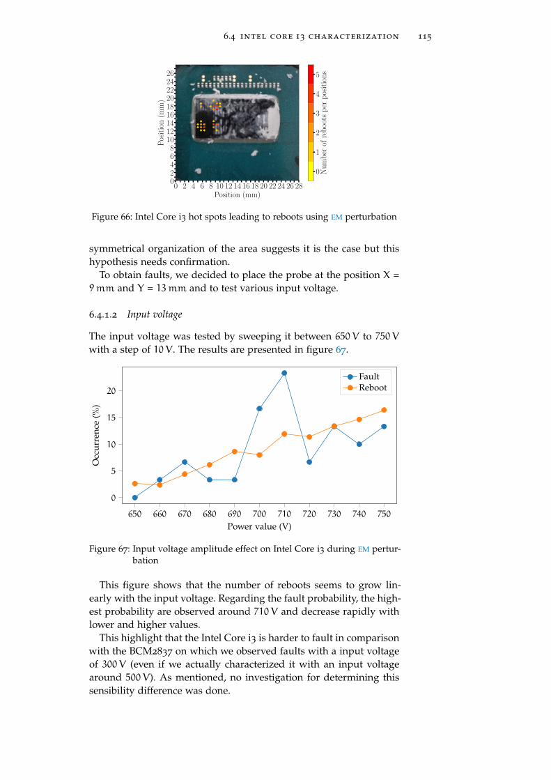
6.4 intel core i3 characterization 115
0 2 4 6 8 10 12 14 16 18 20 22 24 26 28Position (mm)
02468101214161820222426
Position(m
m)
0
1
2
3
4
5
Number
ofreboots
per
positions
Figure 66: Intel Core i3 hot spots leading to reboots using EM perturbation
symmetrical organization of the area suggests it is the case but thishypothesis needs confirmation.
To obtain faults, we decided to place the probe at the position X =9mm and Y = 13mm and to test various input voltage.
6.4.1.2 Input voltage
The input voltage was tested by sweeping it between 650V to 750V
with a step of 10V . The results are presented in figure 67.
650 660 670 680 690 700 710 720 730 740 750
0
5
10
15
20
Power value (V)
Occ
urr
ence
(%)
FaultReboot
Figure 67: Input voltage amplitude effect on Intel Core i3 during EM pertur-bation
This figure shows that the number of reboots seems to grow lin-early with the input voltage. Regarding the fault probability, the high-est probability are observed around 710V and decrease rapidly withlower and higher values.
This highlight that the Intel Core i3 is harder to fault in comparisonwith the BCM2837 on which we observed faults with a input voltageof 300V (even if we actually characterized it with an input voltagearound 500V). As mentioned, no investigation for determining thissensibility difference was done.

116 experimental work
6.4.2 Analyzer results
As on the previous target, we used the analyzer to determine how theIntel Core i3 behave against EM perturbations.
6.4.2.1 Fault probability
The fault probability on the Intel Core i3 was observed to be between0.31% and 0.39% which is up to ten times lower that the fault proba-bility on the BCM2837.
Also, this explained why we could not observe faults during thespatial cartography as we did only 30 tests per position while thereis a fault every 250 attempts on average.
6.4.2.2 Faulted values distribution
Regarding the faulted values distribution, the results for both experi-ments are presented in figures 68 and 69.
0x00000000b7047907
0x0000000000000001
0x00000000b72476b9
0x00007faa06394970
0x00007fada730d970
0x0000000000000002
0x0000000000000003
0x0000000000000000
0x00000000f7a629be0
5
10
15
20
25
Faulted values
Occ
urr
ence
(%)
Figure 68: mov rbx,rbx faulted value distribution on Intel Core i3 using EM
perturbation

6.4 intel core i3 characterization 117
0x4000000000000003
0x0000000000000002
0x3ffffffff
ffffdbd
0x0000000000000008
0x0000000000000003
0x0000000000000000
0x0000000000000004
0x0000000000000246
0x8000000000000004
0x3fffffffb
724f69a
0x40007f5f68c81972
0x40007f0dc62f09720
10
20
30
Faulted values
Occ
urr
ence
(%)
Figure 69: orr rbx,rbx faulted value distribution on Intel Core i3 using EM
perturbation
These results show that the number of observed faulted value isreally lower than the number we observed on the previous targets.This shows that, despite being hard to fault, the faults observed onthe Intel Core i3 are consistent. This suggests that the fault does nothave a random effect on the device.
6.4.2.3 Targeted register
Regarding the targeted register, faulted one is always the one manip-ulated by the instruction, i.e. rbx. As we only execute instructionsinvolving this register, this strongly suggests that we are in a similarsituation than we were on the previous targets.
6.4.2.4 Fault model
For the fault model analysis, the analyzer was not able to determinethe fault model for between 35% to 45% of the cases. This is quitesimilar to our observations on the BCM2837. The fault model distri-bution is shown in figure 70.
Despite the unknown fault model, the only present fault modelsare the “Bit reset”, the “Other obs value” and the “Or with otherobs”. The “after execution” mention comes from the fact that the faultmodels are computed on the values after the faulty execution of thetest program. Indeed, the observed faulted value could be computedusing these fault models on the observed faulted values instead ofthe initial values.
This suggests that the faults first corrupts some registers then cor-rupts the executed instruction.
However, without this particularity, the observed fault models seemto match with the observation we made on the previous targets. In-deed, the “Or with other obs” fault model only appear during theorr rbx,rbx experiment and the “Other obs value” is very present inthe mov rbx,rbx.

118 experimental work
Fault modelunknown
Bit reset Other obsvalue afterexecution
Or with otherobs value after
execution
0
10
20
30
40
50
Fault model
Occ
urr
ence
(%)
mov rbx,rbx
orr rbx,rbx
Figure 70: Probability of observing the different fault models for both exper-iments on Intel Core i3 using EM perturbation
6.4.2.5 Register corruption
As mentioned above, the observed fault always involve a register cor-ruption, however, most of them could not be identified and are con-sidered random.
But some “Bit reset” have been observed. This was already ob-served on the BCM2837 and as said before, it matches the EM per-turbation medium behavior.
6.4.2.6 Instruction corruption
The “Other obs value” fault model is observed on both experiment.As one is based on a orr instruction, it seems that, at least in thiscase, the fault corrupts the instruction opcode. The correspondingfaulted instructions are mov rbx,rdi (50%) and mov rbx,r11 (50%).This shows that the operand is also faulted as on the previous targets.
Considering the mov rbx,rbx experiment, the “Other obs value”fault model is explained with the corruption of the register source ordestination in the instruction. The observed faulted instructions arepresented in table 11.
Faulted instruction Occurrence (%)
mov rbx, rdi 46.15%
mov rbx, rax 38.46%
mov rbx, rcx 15.38%
Table 11: mov rbx,rbx corruptions regarding the “Other obs value” faultmodel
This table shows that the destination register is never faulted butthe source register is. This corresponds to the instruction operand andperfectly matches our observations on the BCM2837. As this target

6.5 characterization conclusion 119
and the Intel Core i3 are very different: different architecture, differ-ent instruction encoding, different process technology and differentcache management, this similarity is very interesting. Despite thesedifferences, as the fault are similar we can conclude that the causesare the also similar.
The last fault model we observed is the “Or with other obs” faultmodel and only appear during the orr rbx,rbx experiment. Thisis again similar to our observations on the BCM2837 and suggestsan operand corruption. The corrupted observed instruction are pre-sented in table 12.
Faulted instruction Occurrence (%)
orr rbx, rax 77.78%
orr rbx, rcx 22.22%
Table 12: orr rbx,rbx corruptions regarding the “Other with other obs”fault model
This table shows that the observed fault model actually comes froma corruption of the operand such as on the BCM2837. This stronglysuggests that the fault is independent from the instruction encodingand effectively targets a mechanism manipulating the operands. How-ever, we identified the cache to be the target micro-architectural, thissuggest that we also perturb it on the Intel Core i3 as we observe thesame behavior.
6.4.3 Conclusion on the Intel Core i3-6100T
This section presents the characterization work we have done on theIntel Core i3-6100T target using our method. This target appeared tobe hard to fault than the BCM2837 and the BCM2711b0 as we neededa stronger EM perturbation to observe faults.
However, contrary to the previous targets, we observe less differentfaults, in other words, the number of observed faulted value is aroundten on the Intel target while it is more around twenty-five on the BCMtargets. However, we did not look into determining the root cause ofthis difference.
A more interesting observation is that the fault model on the Inteltarget is often a second operand corruption, just as on the BCM tar-gets. This suggest that these targets, while being different, are faultedin a similar way.
Therefore, we can suppose that the Intel target and the BCMs sharea mechanism which is faulted in the same way on all targets. Whileit is harder to fault it on the Intel target.
6.5 characterization conclusion
This chapter presented the characterization experiments realized dur-ing this thesis. The characterized target are chosen to be represen-tative of common SoCs one can find in modern digital devices. The

120 experimental work
chosen target are the BCM2837 powering the Raspberry Pi 3 modelB, the BCM2711b0 powering the Raspberry Pi 4 and the Intel Corei3-6100T powering a PC.
These targets represent the two most widespread architectures inSoCs: ARM (BCM2837 and BCM2711b0) and x86 (Intel Core i3-6100T).They were tested against EM perturbation (BCM2837 and Intel Corei3-6100T) and laser perturbation (BCM2711b0).
Despite several constraints, the three targets were characterized atthe ISA level. The conclusions are that faults on all the targets are ableto modify the operands used by the executed instructions. Also, theCPU registers were proven to be corruptible. An in-depth characteriza-tion at the micro-architectural level able to identify that the memorycache is faulted.
Moreover, the targets show a similar faulted behavior despite be-ing manufactured in different technologies, implementing differentarchitecture and being faulted using different injection medium. Thisobservation leads us to the conclusion that the fault model on thesetargets does not depend of these elements but a mechanism they havein common. Even if we know that we fault the cache, we could notprecisely identified the involved mechanism.
Having a common to all SoCs mechanism which behaves in thesame way to different perturbation make these targets quite weak.Indeed, if the faults are repeatable from a SoC to another with a cor-rect probability, any attack realized on a program on a SoC might beapplicable to any other SoC using this program.
This observation make the mitigation of such faults a importantstep. However, in this thesis, to assess the relevance of our character-ization, we did not focus on the design of a countermeasure but onthe exploitability of the characterized faults regarding classical secu-rity softwares embed in SoCs.

7FA U LT M O D E L E X P L O I TA B I L I T Y
Life happens wherever you are, whether you make it or not.
— Uncle Iroh (Avatar: The Last Airbender)
abstract
This chapter presents our work to evaluate Linux programs againstthe faults we characterized in the previous section. We present a DFA
on the OpenSSL implementation of AES, a PFA on our baremetal AES
using persistent faults in the cache. We also realize an analysis ofthe sudo program which involves a user authentication mechanism.This analysis highlight the complexity of such programs and the needof an analysis and fault simulation software we also introduce. Theworks presented in this chapter were submitted in the JCEN jour-nal [159] and in the CHES conference [162].
Contents
7.1 DFA on the OpenSSL AES implementation 123
7.1.1 Source code location 123
7.1.2 Static analysis 124
7.1.3 Fault attack on the OpenSSL AES 126
7.1.4 DFA software 128
7.1.5 Conclusion on the OpenSSL AES DFA 132
7.2 Baremetal AES PFA [159] 132
7.2.1 PFA Result 132
7.2.2 Conclusion on the PFA on our baremetalAES 134
7.3 sudo authentication 134
7.3.1 Attack model 135
7.3.2 sudo analysis 135
7.3.3 Code analysis 141
7.3.4 Program setup 142
7.3.5 Side channel analysis 144
7.3.6 Exploitation 145
7.3.7 Conclusion on the forced authentication 147
7.4 Analysis tools 147
7.4.1 The function analyzer 148
7.4.2 Fault simulator 149
7.5 Evaluation conclusion 151
121

122 fault model exploitability
In this chapter, we aim at evaluating the security of classical Linuxprograms regarding our fault model. The evaluation of such pro-grams is very different from the ones executing on smartcards. In-deed, as they execute on a modern CPU, their execution is not sequen-tial but parallel due to the presence of optimizations as mentionedin section 2.3.2.2. This make the synchronization of the perturbationwith a particular moment of the program execution trickier.
Moreover, Linux programs rely on mechanisms coming from theLinux kernel like the shared libraries. These libraries are either in-cluded in the executable (static linking), loaded at the program startup(dynamic linking) or loaded during the program execution (moduleloading). Therefore, as a Linux program is composed of an executableand several libraries it relies on, its attack surface is important butit is also more complex to analyze it. In particular, due to a lot ofruntime mechanisms, a static analysis of such program may be super-ficial compared with what actually happen at runtime, in particularconsidering faults. Actually, the execution of such programs involvethe execution of the Linux kernel dynamic linker as presented in fig-ure 71.
Dynamiclinker
Dynamiclinker
Shell command
Executable and dynamicdependencies loading
and mapping
Program execution
Modules and dynamicdependencies loading
and mapping
End of execution
dlopen()
Figure 71: Linux dynamic linker interventions during program execution
This figure shows that, on Linux systems, the execution of a pro-gram depending on dynamic libraries involves the execution of a ker-nel piece of code named the dynamic linker which aims at loadingand mapping the needed libraries for the program to execute. Also,a program can call the dynamic linker to load a shared object forexecuting it at runtime using the dlopen() function. Therefore, onlyanalyzing the binary of a program is not enough to asses its securitybut also some kernel mechanisms must be checked. In particular the
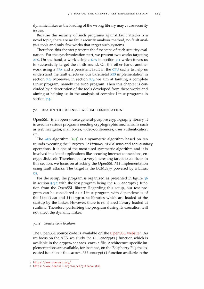
7.1 dfa on the openssl aes implementation 123
dynamic linker as the loading of the wrong library may cause securityissues.
Because the security of such programs against fault attacks is anovel topic, there are no fault security analysis method, no fault anal-ysis tools and only few works that target such systems.
Therefore, this chapter presents the first steps of such security eval-uation. For the synchronization part, we present two works targetingAES. On the hand, a work using a DFA in section 7.1 which forces usto successfully target the ninth round. On the other hand, anotherwork using a PFA and a persistent fault in the CPU cache to help usunderstand the fault effects on our baremetal AES implementation insection 7.2. Moreover, in section 7.3, we aim at faulting a completeLinux program, namely the sudo program. Then this chapter is con-cluded by a description of the tools developed from these works andaiming at helping us in the analysis of complex Linux programs insection 7.4.
7.1 dfa on the openssl aes implementation
OpenSSL1 is an open source general-purpose cryptography library. Itis used in various programs needing cryptographic mechanisms suchas web navigator, mail boxes, video-conferences, user authentication,etc.
The AES algorithm [163] is a symmetric algorithm based on tenrounds executing the SubBytes, ShiftRows, MixColumns and AddRoundKey
operations. It is one of the most used symmetric algorithm and it isinvolved in a lot of applications like securing internet connections, en-crypt disks, etc. Therefore, it is a very interesting target to consider. Inthis section, we focus on attacking the OpenSSL AES implementationusing fault attacks. The target is the BCM2837 powered by a LinuxOS.
For the setup, the program is organized as presented in figure 36
in section 5.3.2 with the test program being the AES_encrypt() func-tion from the OpenSSL library. Regarding this setup, our test pro-gram can be considered as a Linux program with dependencies ofthe libssl.so and libcrypto.so libraries which are loaded at thestartup by the linker. However, there is no shared library loaded atruntime. Therefore, perturbing the program during its execution willnot affect the dynamic linker.
7.1.1 Source code location
The OpenSSL source code is available on the OpenSSL website2. Aswe focus on the AES, we study the AES_encrypt() function which isavailable in the crypto/aes/aes_core.c file. Architecture specific im-plementations are available, for instance, on the Raspberry Pi 3 the ex-ecuted function is the _armv4_AES_encrypt() function available in the
1 https://www.openssl.org/
2 https://www.openssl.org/source/gitrepo.html

124 fault model exploitability
crypto/aes/asm/aes-armv4.pl file. However, our analysis on assem-bly code will not come from this file but directly from the disassemblyof the program. The reason is that the ARMv4 specific implementa-tion is embedded in a Perl script which realizes some optimizations.Therefore, disassembling the binary gives the closest-to-reality assem-bly code.
7.1.2 Static analysis
Before evaluating the AES implementation, we realize a static analysisof the source code and binary to determine whether the determinedfault model reveals exploitable vulnerabilities.
7.1.2.1 AES round optimization
The AES_encrypt() function is optimized to have the lowest executiontime. This optimization is obtained by using pre-computed tables forevery SubBytes and MixColumns operations. The listing 7.1 presents apart of these tables.
1 static const u32 Te0[256] =
2 0xc66363a5U, 0xf87c7c84U, 0xee777799U, 0xf67b7b8dU,
3 0xfff2f20dU, 0xd66b6bbdU, 0xde6f6fb1U, 0x91c5c554U,
4 0x60303050U, 0x02010103U, 0xce6767a9U, 0x562b2b7dU,
5 0xe7fefe19U, 0xb5d7d762U, 0x4dababe6U, 0xec76769aU,
Listing 7.1: OpenSSL AES pre-computed tables (partial)
The Te0 table corresponds to the operation presented in equation (35)with S the SubBytes operation.
Te0[x] = S(x) · [2, 1, 1, 3] (35)
Equation: Pre-computation of the Te tables in the OpenSSL AES
This operation realizes the computation of the first column of thenext AES state. Corresponding tables Te1, Te2, Te3 are also pre-computedfor the others columns. In the end, the outputs of these tables a recom-bined to obtain the current round AES state. The listing 7.2 presentshow the states are recombined.
The recombination of the states consists in XORing the output of thetables between them and with the current round key rk. The tableaccess is done by switching and masking the current state (s0, s1, s2,s3). The full computation consists in a loop repeating these operationsalternating between the tX and the sX states as input/output of thetables.

7.1 dfa on the openssl aes implementation 125
1 t0=Te0[(s0>>24)] ^ Te1[(s1>>16)&0xff] ^
Te2[(s2>>8)&0xff] ^ Te3[s3&0xff] ^ rk[4];→
2 t1=Te0[(s1>>24)] ^ Te1[(s2>>16)&0xff] ^
Te2[(s3>>8)&0xff] ^ Te3[s0&0xff] ^ rk[5];→
3 t2=Te0[(s2>>24)] ^ Te1[(s3>>16)&0xff] ^
Te2[(s0>>8)&0xff] ^ Te3[s1&0xff] ^ rk[6];→
4 t3=Te0[(s3>>24)] ^ Te1[(s0>>16)&0xff] ^
Te2[(s1>>8)&0xff] ^ Te3[s2&0xff] ^ rk[7];→
Listing 7.2: OpenSSL AES round computation (C)
7.1.2.2 OpenSSL AES vulnerability analysis.
Regarding the source code of an AES round presented in listing 7.2,we can see that the involved operations are: the logical right shift, thelogical AND, the logical XOR and a memory access to the tables. As aconsequence, the assembly code for a round will only use ldr, and,eor and lsr instructions. This is confirmed by the disassembled codeof the AES_encrypt() function available in appendix E.
These instructions are very similar to the instructions we used insection 5.3.2.1 for characterizing the fault model on our targets. There-fore, we know that we have a high probability to modify the secondoperand of these instructions.
Also, for the DFA (presented in section 4.4.1.1), we want to fault onlyone byte in the AES state before the last MixColumns. As many instruc-tions manipulate 32 bits wide register, faulting the second operandwill mainly fault 4 bytes. If the 4 bytes are in different columns, theobtained cipher is still usable for a DFA and even leak informationon 4 bytes of the key. However, as we presented earlier, the opera-tions are done column by column and therefore, faulting a registerwill mainly modify the entire column making the faulted cipher notexploitable. This eliminate any fault on the ldr, eor and lsr instruc-tions.
However, there are the and instructions that remain and they areused to apply a byte wide mask on the register. Faulting the secondoperand of these instructions (i.e. the used mask) will results in ap-plying a byte wide fault on the result. This corresponds to the faultwe want to obtain for the DFA.
According to the AES_encrypt() assembly code available in ap-pendix E the and instructions represent 23% of the instructions com-posing an AES round. As presented in section 6.2.2.1, we have 1%fault probability on and instructions. Therefore, in first approxima-tion (by considering all instructions have the same execution time),we can suppose that the probability to obtain a usable cipher for aDFA is around 0.23% per injection. In other words, around 400 faultinjections are needed before having a usable cipher. As 8 ciphers areneeded for a complete DFA, we can suppose that around 3200 injec-tions are needed for obtaining all the ciphers needed for the DFA.

126 fault model exploitability
In practice, the instructions does not have the same execution time,in particular the memory access instructions (ldr) are, in general,slower than the data processing instructions (and, eor and lsr). How-ever, estimating the execution time is a tricky job as, due to CPU opti-mizations [164, 165] (cache, fill buffers, etc), this time is quite variable.However, these optimizations aim at making a memory access as fastas a data processing instruction, making our hypothesis relevant.
7.1.3 Fault attack on the OpenSSL AES
Based on the analysis, we know that our fault model is relevant forattack the OpenSSL AES implementation in 3200 injections. The nextstep naturally consists in testing if we actually can realize this ex-ploitation on an implementation running on the BCM2837.
7.1.3.1 Synchronization
As explained in section 2.3, SoCs are multi-core and multi-threadedsystems with various optimizations. This architecture brings a nonsequential execution of instructions composing a program. Therefore,synchronizing a fault injection with a particular moment of the pro-gram execution (in our case: before the last MixColumns operation) isa tricky business.
As we do not have information nor a method to synchronize ourperturbation with the program, we decided to sweep over the AES
execution and analyze the fault probability and the number of faultsdiagonals regarding the delay between the start of the AES compu-tation and the moment we perturb it. These results are presented infigures 72 and 73.
2 2.5 3 3.5 4 4.5 5 5.5 6
·10−7
1
2
3
4
5
Delays (s)
Fau
lt(%
)
Figure 72: Impact of the delay on the probability while faulting an OpenSSLAES encryption using EM perturbation on BCM2837.
The figure 72 shows that the fault probability has a tendency todecrease while we increase the delay before doing the perturbation.However, we did not make a further researches to determine the ori-gins of this phenomena.

7.1 dfa on the openssl aes implementation 127
2 2.5 3 3.5 4 4.5 5 5.5 6
·10−7
0
5
10
15
Delay (s)
Nu
mbe
rof
fau
lted
cip
hers
Number of faulted diagonals:01234
Figure 73: Impact of the delay on the number of faulted diagonals whilefaulting an OpenSSL AES encryption using EM perturbation onBCM2837.
The figure 73 presents the number of faulted ciphers with a specificnumber of faulted diagonals regarding the delay before the perturba-tion. 0 diagonals faulted means that the cipher is faulted but not witha diagonal pattern.
These results shows us that the number of ciphers with less than 4
faulted diagonals faulted is quite constant and therefore independentof the injection timing. However, the number of ciphers with 4 faulteddiagonals decreases when the delay before the perturbation increase.This is understandable because, in the AES, any fault that appears onat least a byte is diffused on the whole cipher after the execution ofa MixColumns, ShiftRows and an other MixColumns sequence. In otherword, any fault before the before-last MixColumns (the one during the8th round) leads to a fully faulted cipher, i.e. the four diagonals arefaulted, but this kind of cipher is not suitable for a DFA.
When the perturbation occurs after the before-last MixColumns, thediffusion of the fault is limited to the diagonals containing the initialfaulted bytes. Supposing that faulting four bytes with each byte ondifferent diagonal is less probable than faulting a single byte. Thenumber of cipher with four faulted diagonals should drop whenthe perturbation occurs after this MixColumns. This seems to happenaround 400ns of delay. Also, we could expect that, after this delay,the number of ciphers with less than 4 faulted diagonals will increase,but we do not observe such phenomena.
As mentioned above, the number of ciphers with less than 4 faulteddiagonals remains almost constant independently of the delay. Thisobservation is complicated to explain as before the before-last MixColumns,we should observe only fully faulted ciphers and after this MixColumns,a more regular distribution should be observed. But it is not the case.Regarding the figure 72, our observation seems to correlate with thefault probability, i.e. after 400ns of delay the probability to obtainciphers with 4 faulted diagonals decrease while the probability toobtain ciphers with less than 4 faulted diagonals remains constant.
128 fault model exploitability
This correlation is unnatural as there is no reason which mightexplain that the probability of having 4 faulted diagonals decreasewhile the probability of having less than 4 faulted diagonals remainsconstant, and must be studied carefully. Our opinion is that severalphenomena occur. The first one is that, because we passed the before-last MixColumns, the distribution of the number of faulted diagonalsis quite balanced (when the delay is greater than 400ns). The sec-ond one is that, for an unknown reason, passing this delay the faultprobability decrease.
Despite we think this is the best explanation of these observations,we do not know why the fault probability would decreased after thisdelay and we cannot explain why we observe ciphers we less than 4
faulted diagonals before this delay. This result is an example of thecomplexity induced by the CPU architecture regarding synchroniza-tion and our lack of knowledge about how programs are executedwithin these CPUs.
However, we were able to obtain ciphers with only one faulteddiagonal making the DFA possible. Therefore, we focused on usingthese faulted ciphers to realize our DFA.
7.1.3.2 Exploitability
The faults campaign consisted of 3000 injections (up to 3200 are re-quired for a complete DFA regarding our analysis) and around anhour is needed to achieve them with our setup. Among these injec-tions, we obtained 466 faults (15.54%). By all of these faults, only 16
have a single faulted diagonal (4.348%) and considering these faultedciphers; only 8 correspond to a one-byte fault before the MixColumns
operation. Also, faults appear with the same probability on every di-agonal.
In the end, the probability of obtaining a suitable faulted cipher forthe DFA is 0.34% which corresponds to 1 cipher every 294 injectionswhich is a bit better than the rate we extrapolated from the analysisabove (0.23%). This difference might be due to the hypothesis wemade that any fault on instructions other than and instruction will notgive any interesting faulted cipher. Indeed, it is possible by faulting a4 bytes register that the fault affects only one byte.
Considering an injection needs 2 seconds, we obtain a usable cipherevery 10 minutes. As 8 ciphers are needed for the complete DFA andbecause every diagonal has the same probability to be faulted, 3 hoursof injection are enough to obtain the needed ciphers.
7.1.4 DFA software
To do the DFA, we developed a C program which aims at realizingit. As the DFA able to retrieve the key bytes diagonal per diagonal,our program works only on a diagonal. Therefore, its inputs are thefaulted ciphers and the diagonal index to work on.
After our experiments, we sort the suitable ciphers and stored themin different files named ciphers_diagX.txt where X is the diagonal

7.1 dfa on the openssl aes implementation 129
index. Our DFA program then reads the ciphers contained in the fileand use them to realize the DFA as explained on figure 29 in sec-tion 4.4.1.1.
The possible ∆ values are pre-computed using a Python script andstored in a header file. Then the program computes the ∆ value forevery possible key diagonal (232 values) for every faulted ciphersstored in the input file. The loop doing this is presented in listing 7.3.
137 for(uint64_t value = 0; value < MAX_VAL_32BITS; value++)
/* Key bytes */→
138 /* Computing the reversed good cipher */
139 int_to_bytes((uint32_t)value, k_diag, AES_DIAG_SIZE);
140 xor_array(c_diag, k_diag, c_xor, AES_DIAG_SIZE);
141 inv_s_box_array(c_xor, c_sub, AES_DIAG_SIZE);
142
143 k_is_good_candidate = 1; /* Check if we have a good
candidate */→
144 for(i=0; i<nb_faulted_ciphers; i++) /* Test over all
faulted ciphers */→
145 f_str = faulted_ciphers[i];
146 hex_str_to_bytes(f_str, f_bytes, AES_NB_BYTES);
147 extract_diag(f_bytes, f_diag, diag, AES_DIAG_SIZE);
148 /* Computing the reversed faulty cipher */
149 xor_array(f_diag, k_diag, f_xor, AES_DIAG_SIZE);
150 inv_s_box_array(f_xor, f_sub, AES_DIAG_SIZE);
151 /* Computing the delta */
152 xor_array(c_sub, f_sub, delta, AES_DIAG_SIZE);
153 /* Check if delta is in possible values */
154 delta_val = (uint32_t)bytes_to_int(delta,
AES_DIAG_SIZE);→
155 k_is_good_candidate = k_is_good_candidate &
156 is_in_array(mix_col_diff_list,
157 delta_val,
158 NB_MIX_COL_VALUES);
159
160
161 if(k_is_good_candidate) /* Print the key diagonal */
162 printf("\rKey diagonal %d = 0x%08x\n", diag,
(uint32_t)value);→
163
164
165 printf("\r0x%08x", (uint32_t)value); /* Print the last
tested key */→
166 fflush(stdout);
167
Listing 7.3: DFA program main loop
This listing shows the loop iterating over the possible key values (line137) and then computing the correct cipher last round reverse: the

130 fault model exploitability
left term of equation (21) in section 4.4.1.1 (lines 139 to 141). Thesecond part consists in computing the right term of equation (21) forevery faulted ciphers (line 144 to 150) and then compute the deltavalue (line 152). Then we check if the key candidate is a good one bychecking if the delta value is among the possible output values of afaulted MixColumns (line 155).As one can note, despite we work on 32 bits, we have to convert ourvariables into byte arrays. The reason is the SubBytes operation whichinvolves SBoxes. Despite manipulating byte arrays is slower than ma-nipulating 32 bits data, the storing of the SBoxes requires 256B (28 B)of memory when working with bytes and 16GB (4× 232 B) of mem-ory when working with 32 bits data. We therefore decided to workwith bytes array to lower the memory footprint of our program.However, we developed a Python script which generates the 32 bits
SBoxes but we did not tested it. As a consequence we do not knowhow much faster a fully 32 bits program would be. Also, regardinglisting 7.3, the program is not optimized in memory as we use everybuffer only once while we could reuse them between two operations.This choice was made to keep a good clarity in the source code.
7.1.4.1 Usage and results
The usage of the program is straightforward, the program will lookfor the ciphers_diagX.txt files and computing the correct diagonalusing the passed argument such as in listing 7.4.
> ./aes_dfa 0
> Key diagonal 0 = 0x132ba717
Listing 7.4: Example usage and result of the DFA program on the first diago-nal
Currently the correct cipher is hard coded in the program and is pre-sented in listing 7.5.
112 char* c_str = "69c4e0d86a7b0430d8cdb78070b4c55a";
Listing 7.5: AES correct key as implemented in the DFA program
However, this is a bad coding habit and a program enhancement willbe to pass this key as a parameter. The results presented in listing 7.4were obtained using the faulted ciphers introduced in listing 7.6.
9fc4e0d86a7b04aed8cda980708dc55a
11c4e0d86a7b0446d8cd60807094c55a
Listing 7.6: Faulted ciphers used in our DFA (ciphers_diag0.txt)
7.1.4.2 Performance
From 2 faulted ciphertexts with the same faulted diagonal, our pro-gram is able to recover the 4 corresponding bytes of the key in an

7.1 dfa on the openssl aes implementation 131
hour on average. The computer used for this computation is poweredby an Intel(R) Core(TM) i7-8550U CPU clocked at, at least, 1.80GHz
with 16GB of memory.As our implementation works per diagonals, it is possible to run fourinstances of the program and therefore realize the cryptanalysis onthe four diagonals in parallel. However, this require four times morememory at the moment, indeed the pre-computed SBoxes are notshared between these instances making the usage of byte arrays evenmore relevant. But, sharing the SBoxes using multiple threads willdivide the memory footprint by 4, making it a great improvement todo.Finally, once we obtained the faulted ciphers, only 1 hour is neededto recover the key. Adding the time needed to obtained these faultedciphers, the complete cryptanalysis can be achieved in less than 4
hours.This timing considers that the hot spots determination and the faultcharacterization are already done. These steps require at least a weekof work but the results are reusable on every target powered by thecharacterized device. Also, the algorithm consider that every pro-vided faulted cipher is relevant for realizing the DFA, which is, inpractice, not the case.
7.1.4.3 Detecting the relevance of faulted ciphers
To do a DFA, we use ciphers with one diagonal faulted. However,this diagonal must be faulted with a specific pattern, i.e. the faultmust comes from a one byte faulted before the MixColumns operation.However, it happens that we observe a cipher with a diagonal faultedwhile it does not comes from a fault on a byte before the MixColumns.In can be only the four bytes faulted independently for instance. Insuch case, the cipher is not exploitable for a DFA.In our case, as we fully master the implementation, we could verifyif a faulted cipher match a fault on a byte before the MixColumns.However, this verification needs the knowledge of the key, which isirrelevant in a practical attack but relevant in the case we just want toassert our faults are suitable for a DFA.Therefore, to adapt our DFA program to avoid this verification is to im-plement an enumeration protocol which tests several faulted cipherspairs. Indeed, when we realize the DFA, the correct key is recoveredin 98% of the cases with two ciphers. Therefore, when a key does notmatch with two given ciphers, there is two cases: either it is not thecorrect key or the used faulted cipher does not match a fault on abyte before the MixColumns and more ciphers must be tested.In practice, the ratio of the number of suitable for DFA faulted ciphersagainst the number of ciphers with only one diagonal faulted canonly be determined with the knowledge of the key or by successfullyrealize the attack. In our experiment, we determine that 50% of theciphers with one faulted diagonal are suitable for a DFA.Therefore, the last improvement we can do for our DFA software isthe implementation of a smart way to test the different ciphers with-

132 fault model exploitability
out knowing if they are actually suitable for a DFA. Of course, thiswill make the algorithm slower depending on our capacity to havesuitable faulted ciphers.
7.1.5 Conclusion on the OpenSSL AES DFA
In this section, we successfully attack the OpenSSL AES running on aBCM2837 using a DFA. We saw, via a static analysis, that the OpenSSLimplementation of the AES is sensitive to faults regarding our faultmodel. We computed a success rate from this analysis.By faulting the AES, we observed a greater success rate than the onewe initially computed (ignoring instruction execution time variabilityand CPU optimizations). We also observe interesting behavior regard-ing our moment of injection. Indeed, the fault probability and thenumber of ciphers with four faulted diagonals have a tendency to de-crease while we increase the delay between the start of the AES andthe perturbation. We did not make further research to explain thisphenomena but it shows that the CPU complexity can lead to interest-ing observation regarding synchronization.Despite these undetermined behaviors, we were able to obtain suit-able faults for realizing the DFA with a self-programmed software inaround an hour.
7.2 baremetal aes pfa [159]
The work presented in this section aims at assessing that the persis-tent faults in the data cache observed in section 6.2.4.3 are suitable foran exploitation. The reason is that these faults are particularly power-ful regarding our target as they do not need to be synchronized withthe program execution but only have to exist. However, due to timeconstraints we did not realized this experiment on a Linux system.Therefore, in this section, we realize a PFA (introduced in sec-tion 4.4.1.1) on an AES we implemented on our baremetal setup onthe BCM2837.Our AES implementation is a naive one without countermeasures.The SBoxes are implemented with a lookup table. Before the actualencryption, we pre-warm the cipher. In other words, to limit timingleakages due to caches, we invalidate the instruction and data caches,then we perform a dummy AES encryption to fill the caches with dataand instructions of interest. This is the step where we inject the fault.In a second step, we encrypt 10 000 random plaintexts, without anynew fault injection, and try to deduce the key from the observedfaulty ciphers.
7.2.1 PFA Result
To detect the forbidden values, we simply count the number of oc-currences for all bytes values in the ciphertext, for the first byte, thenthe second byte, etc. On figure 74, one can observe that 2 values are

7.2 baremetal aes pfa [159] 133
forbidden. Therefore, in our case, two bytes have been faulted in theSBox lookup table.
0 100 200 2500x23 0x8f
0
20
40
60
80
Ciphers first byte value
Occ
ure
nce
Occuring valuesForbidden values
Figure 74: Distribution of the first byte for 10 000 faulted ciphers on ourbaremetal AES on the BCM2837.
Therefore, the analysis presented in section 4.4.1.1 must be adaptedto the two faults case. For each byte index from 0 to 15, we get thetwo forbidden values. They are shown in Table 13.
Index 0 1 2 3 4 5 6 7
Forbidden 23 21 2d 4f 7f 08 7a 27
values 8f 8d 81 e3 d3 a4 d6 8b
Index 8 9 10 11 12 13 14 15
Forbidden 6f 37 3b 17 7d 1b 00 59
values c3 9b 97 bb d1 b7 ac f5
Table 13: Forbidden values for every byte of the observed ciphers.
Since we have 2 forbidden values y1 and y2 per byte, we have 224
key hypotheses. First, we have 28 guesses for y1 (or y2 as they canswap but only one is needed) then, among the two forbidden valuesfor each byte, we must find the one giving the key regarding our y1
(216 possible choices). The possible key bytes for a correctly guessedforbidden value y1 = 0x30 are displayed in table 14. In other words,table 14 is table 13 XORed with y1. Finding the key then consists inchoosing the correct value (shown in red on table 14) out of the two,for each byte index.The correct key is 13 11 1d 7f e3 94 4a 17 f3 07 a7 8b 4d 2b 30
c5. In total, we have 224 key hypotheses, with a pair of plaintext andcorresponding ciphertext to validate the correct key, recovering theAES key can be done on a desktop computer in a few minutes. Ittakes 145 s on an Intel Xeon E5-1620 v3 CPU to find y1 = 0x30, so itwould take by extrapolation 757 s, or less than fifteen minutes, to testall keys.

134 fault model exploitability
Index 0 1 2 3 4 5 6 7
Forbidden 13 11 1d 7f 4f 38 4a 17
values bf bd b1 d3 e3 94 e6 bb
Index 8 9 10 11 12 13 14 15
Forbidden 5f 07 0b 27 4d 2b 30 69
values f3 ab a7 8b e1 87 9c c5
Table 14: Possible key bytes for the correct guess y1 = 0x30 with the correctkey in red.
7.2.2 Conclusion on the PFA on our baremetal AES
In this section, we presented a PFA we realized on a self-developedAES on our BCM2837 baremetal setup. The fault is coming from acorruption of the data cache and is persistent. In other words, thefault remains in place while the cache is not invalidated.This fault able us to obtain 10 000 ciphers from different plaintextsand identify forbidden values for each of their bytes. However, duringour experiments we observed two forbidden values per byte whichmeans that we faulted two SBoxes stored in the cache. This showsthat the EM injection medium have an important spreading.But, by adapting the PFA presented in section 4.4.1.1, we were able toreduce the number of possible keys from 2128 to 224.
7.3 sudo authentication
In this section, we aim at evaluating the feasibility of faulting a com-plex Linux program, i.e. a program that both load shared librariesat startup and during its runtime. Also, we want to target a securityoriented program.Therefore, we decided to work on the sudo-based authentication pro-cess of a Linux system. This is an interesting target because the Linuxkernel allows several users on the same device. Usually, for everydays tasks, the usual user has a limited access to the system, this en-sure that he cannot mess up the system configuration while workingor access another user protected files. Also, many other users can beconfigured for different purpose, a famous one is the www-data userwhich is allowed to execute HTTP requests, i.e. requests coming fromunknown person via internet.The critical operations, like updates or security configuration for in-stance, must be done by an unrestricted user, usually known as root.A restricted user can be allowed to obtain the root privileges for amoment to realize some critical operations if it belongs to the correctgroup: sudoers or wheel for instance. Some Linux binaries allow tochange the current user like su or sudo, but they require an authenti-cation.

7.3 sudo authentication 135
7.3.1 Attack model
The program we decide to target is sudo. This program allows a userto fake another user identity if he is allowed to. Most of the time,it is used for granting root privileges for a specific operation. Usersallowed to have the root privileges are called sudoers.Regarding this program, there are three attack models.
1. The attacker has access to a sudoer user session but does notknow its password. This situation can be achieved by being ableto execute arbitrary code via a user application. In this case,the attacker can execute code as the compromised user but theLinux segregation mechanism prevents him to access the otherusers domain.
2. The attacker has the credentials of a user on the system whichis not a sudoer. In this case, the user is not allowed to fake theroot identity and the attacker is therefore limited to the com-promised user domain. This is the typical situation on shareddevices.
3. The attacker has access to a user session without knowing itscredentials and which is not a sudoer.
In this work, we focus on the first case which corresponds to forcethe authentication of the compromised user asked by the sudo binarywithout knowing the user’s password.
7.3.2 sudo analysis
Contrary to what we have done with the OpenSSL AES in section 7.1,we do not develop a test program for the sudo program. We focuson the binary available in the Debian distribution. This is challengingbecause, to evaluate such program, we need to fully understand itsarchitecture and to identify its interesting pieces of code, both in thebinary and in the code source. Regarding our work, an interestingpiece of code is a part of the code that might lead to an unwantedauthentication if it is perturbed.As a first step, we want to analyze the functions that are involved inthe authentication process, in other words, the function that actuallyrealize the password verification and all the calling functions that, ata moment, manage the information (an integer in the sudo) that theauthentication succeed or failed.Then our first goal is identify these functions in the source code andidentify in which binary their assembly code is stored for execution.To do so, there are two strategies:
1. the static top down approach, we find the main function of theprogram in the source code and get down through the differentcalls until we find the function that generates the informationthat the authentication succeed or not. This might seems to be agood approach, but as presented in figure 71, on Linux systems,

136 fault model exploitability
a program can load a shared library at runtime and call a func-tion from it. This actually happen early in the main of the sudo
program. Therefore, from this point, the best we can do is bet-ting on the loaded shared library and the called function whichrequire an important knowledge about the evaluated program.
2. The other approach is a bottom up analysis at runtime. Thisanalysis consists in using a debugger on the target program.The idea is to identify a function that we now (for sure) is calledin the process and put a break point on it. Once this function isexecuted we identify which function called it and we repeat thisuntil we reach the main function. This approach is very effectiveas it able to identify all the called functions, it also able to iden-tify the shared libraries that are involved. This is very importantbecause the knowledge of which libraries a program relies onis not necessary a common knowledge. The only drawback isthat we must know a function that is called during the processwe want to analyze. Also, this function must be the lowest pos-sible in the function calls so we do not miss any of them. If ithappens that our starting function still calls other ones, we cantry to identify them using the source code, and hoping there arenot runtime resolution anymore.
Regarding these strategies, the one we have chosen is the second. Thereason is that we think that analyzing the execution of a program atruntime is more relevant and less time consuming than analyzing itssource code. For instance, the only sudo source code is composed of2492 files (find ./ -type f | wc -l) worth 73MB of code (du -sh
./) and the sudo program relies on many other libraries.
7.3.2.1 Runtime analysis
To realize the runtime analysis, we placed ourselves on a fully mas-tered setup (i.e. with root privileges) and we used the gdb program.As mentioned above, the analysis consists in putting a break point ona function we know for sure is called during our process. Consideringthe sudo program, we know that it will compare two hashes (one ob-tained from the user typed password and one from the /etc/shadow
file). Therefore, we are confident that the strcmp function will becalled and is the lowest function in the call tree. So, we start the sudo
program in a terminal using the sudo ls command for instance. Then,start gdb and attack the sudo process to it using gdb -pid $(pidof
sudo). Then we put a break point on strcmp using the b strcmp com-mand and let the sudo program run using the cont command. Afterhaving typed a password as sudo ask, our debugger must reach thebreak point.At this moment, the process is stopped at the start of the strcmp func-tion and all the already called functions can be shown using the where
command. However, it turns out that the strcmp function is calledmany times in the sudo program (for checking that the user asking forroot privileges is actually in the sudoers group for instance). There-

7.3 sudo authentication 137
fore, we must determine if we are in the correct call of the strcmp
function, i.e. the one that actually compare the hashes. To do so, wedisplay the arguments given to the function. According to the Intelcalling convention, during a function call, the first two arguments arestored in rdi and rsi (r0 and r1 for ARM). The content of these regis-ter can be displayed using the x/1s $REGISTER_NAME command (x/1s$rdi and x/1s $rsi in our case).If the inputs looks like we are comparing hashes, it means we havereached our point of interest. In the case we did not, we can let theprogram executes and reach the next strcmp call using the cont com-mand.As strcmp is called many times, it is interesting to automatize thesesteps using the commands command as shown in listing 7.7.
1 # On first terminal
2 $ sudo ls
3
4 # On second terminal
5 # As root
6 $ gdb --pid $(pidof sudo)
7 # Break if the first character in rdi is '$'
8 (gdb) b strcmp if *(char*)$rdi == 0x24
9 (gdb) commands
10 > x/1s $rdi
11 > x/1s $rsi
12 > where
13 > cont
14 > end
15 (gdb) cont
Listing 7.7: Commands to identify the strcmp calls of the sudo program us-ing gdb.
Using these commands, many results will show up but one of themwill appear to compare hashes as presented in listing 7.8. Also, as weknow that we want to compare hashes and we know that they startwith the $ character, we can customize the break point to break onlyif the first character of the rdi register starts with $ such as down inlisting 7.7 on line 8.This result shows that we are calling the __strcmp_avx2() functionfrom the libc.so (line 1). It also shows the two passed arguments onthe lines 2 and 3 which are hashes with a common prefix. The nextlines (4 to 17) show the functions that actually are on the function callstack, in other words, all the functions called from the main program.We can note that we are in an easy case because we are able to effec-tively identify the correct strcmp function. But it might happen thata process creates a new one (using fork() or clone()) which is usedfor doing the comparison for instance. In this case, we could not findthe correct strcmp call because the child process would have a new

138 fault model exploitability
1 Breakpoint 1, 0x00007f7630680f60 in __strcmp_avx2 () from
/usr/lib/libc.so.6→
2 0x55cbf54a8b00: "$6$UxZjWMS1PnDbraCq$O74AxFWWRjkEZnSqO9jobFgl9yn ⌋
O8cxq8/S5f1tu7ZEPxmXoPOq/ZFtgoKzD3LbAl/fXdZvZ.oCYbFea5cgvo1"→
3 0x55cbf547db40: "$6$UxZjWMS1PnDbraCq$nwD.rOgcz/bgOtx6dpUABwRkCgZ ⌋
Srlj0O9RhmodmC.bmS.n5TxdXG803C95HnHAs9hM4yJ2Li80pMnDUPJ1b60"→
4 #0 0x00007f7630680f60 in __strcmp_avx2 () from /usr/lib/libc.so.6
5 #1 0x00007f763074a60a in ?? () from /usr/lib/security/pam_unix.so
6 #2 0x00007f7630749d9f in ?? () from /usr/lib/security/pam_unix.so
7 #3 0x00007f7630747b46 in pam_sm_authenticate () from
/usr/lib/security/pam_unix.so→
8 #4 0x00007f7630038882 in ?? () from /usr/lib/libpam.so.0
9 #5 0x00007f7630038181 in pam_authenticate () from /usr/lib/libpam.so.0
10 #6 0x00007f7630052a12 in ?? () from /usr/lib/sudo/sudoers.so
11 #7 0x00007f7630051b45 in ?? () from /usr/lib/sudo/sudoers.so
12 #8 0x00007f7630053d44 in ?? () from /usr/lib/sudo/sudoers.so
13 #9 0x00007f7630070f2e in ?? () from /usr/lib/sudo/sudoers.so
14 #10 0x00007f7630068e0e in ?? () from /usr/lib/sudo/sudoers.so
15 #11 0x000055cbf4a9f520 in ?? ()
16 #12 0x00007f763054b152 in __libc_start_main () from /usr/lib/libc.so.6
17 #13 0x000055cbf4aa178e in ?? ()
Listing 7.8: gdb output of a strcmp call comparing two hashes.
PID. PID which we used to attach the process to gdb using the gdb
--pid $(pidof sudo) command.Using this result, we are able to identify that there are thirteenfunctions that manipulate the information about the authenticationand even the shared libraries they are in (libc.so, pam_unix.so,libpam.so and sudoers.so). However, we do not have the name ofevery function (some are displayed with ??). The reason is that theshared libraries only store the function name of the functions that aresupposed to be exported and used by other programs. This nameis useful for the dynamic linker to resolve the function calls. Theother functions are private to the shared library and therefore arestatically linked in the library itself. Therefore, not storing their namesave some memory space.To identify these functions, there are two strategies:
1. the static analysis on the source code. By knowing some func-tions involved in the call tree, we can try to determine in thesource code which functions are calling them and so on. Re-garding the result in listing 7.8, this may easily work for thepam_sm_authenticate() but hardly with the strcmp one as it iscalled a lot.
2. The other solution is to redo the runtime analysis after havingreplaced the used shared libraries by the same but with debugsymbols. These debug symbols will be identified by gdb andtherefore displayed. However, this require to recompile theselibraries.
The solution we have chosen is the runtime analysis with the debugsymbols. The reason is that we think it is more relevant to analyzethe process at runtime.

7.3 sudo authentication 139
7.3.2.2 Recompile Debian package from source
As mentioned, we aim to recompile the packages used in the sudo
authentication with debug symbols. The Debian distribution allowsto do it easily with various tools. The files we want to analyze are thepam_unix.so, the libpam.so, the sudoers.so and the sudo executable.To recompile a package, we must start by identify it using the dpkg
-search command. For instance to determine the package contain-ing the sudoers.so file we use dpkg -search sudoers.so. To haveall the interesting shared object recompile with debug symbols wemust recompile the following packages (on a Debian 10.1.0 distri-bution): sudo, libpam0g:amd64 and libpam-modules:amd64. Some ofthem have the mention amd64 which is an indication of the supportedarchitecture and might change depending on the target we are recom-piling on.Once we have identified the packages to recompile, we must in-stall the dependencies needed for the package using the apt-get
build-dep command. For instance, for the sudo package we doapt-get build-dep sudo.Then we can download and compile the package using thefollowing command: DEB_BUILD_OPTIONS="sotrip noopt" fakeroot
apt-get -b source sudo (for the sudo package).Once we have compiled all our packages, we can install them usingthe dpkg -i command such as dpkg -i sudo_1.8.27-1+deb10u2_-
amd64.deb for the sudo package.Finally, we can do the manipulation presented in listing 7.7 and weobtain a result similar to what is presented in listing 7.9.
1 Breakpoint 1, __strcmp_avx2 () at ../sysdeps/x86_64/multiarch/strcmp-avx2.S:92
2 92 ../sysdeps/x86_64/multiarch/strcmp-avx2.S: No such file or directory.
3 0x5637b173b050: "$6$hH.15uU5laaxuXHY$wtSOcCKWmY1JmyY2CWlVs/8ixyON36ZxQV2RpMJkITzqkIM18lyXNMICoYNIVDe⌋UVXqH0Fs390nl6Lw8m5ArZ0"→
4 0x5637b173a200: "$6$hH.15uU5laaxuXHY$4b7acwY3u21L9Wd8TxQeCIkpmasNufgDzIrScjXreP8oFQA4c.0nZmcYJB2zf5p⌋6rDvPdBC0Fo6JWvquBKaVc."→
5 #0 __strcmp_avx2 () at ../sysdeps/x86_64/multiarch/strcmp-avx2.S:92
6 #1 0x00007fb956a006a0 in verify_pwd_hash (p=0x0, hash=0x5637b173a200 "$6$hH.15uU5laaxuXHY$4b7acwY3u21L9Wd8⌋TxQeCIkpmasNufgDzIrScjXreP8oFQA4c.0nZmcYJB2zf5p6rDvPdBC0Fo6JWvquBKaVc.", nullok=0x0) at passverify.c:124→
7 #2 0x00007fb956a00050 in _unix_verify_password (pamh=0x5637b173fd30, name=0x5637b173fed0 "toto",
p=0x5637b173aad0 "", ctrl=0x40800400) at support.c:792→8 #3 0x00007fb9569fc6fb in pam_sm_authenticate (pamh=0x5637b173fd30, flags=0x8000, argc=0x1,
argv=0x5637b1734620) at pam_unix_auth.c:177→9 #4 0x00007fb956a1c024 in _pam_dispatch_aux (pamh=0x5637b173fd30, flags=0x8000, h=0x5637b173c980,
resumed=PAM_FALSE, use_cached_chain=0x0) at pam_dispatch.c:110→10 #5 0x00007fb956a1c62c in _pam_dispatch (pamh=0x5637b173fd30, flags=0x8000, choice=0x1) at pam_dispatch.c:411
11 #6 0x00007fb956a1b68b in pam_authenticate (pamh=0x5637b173fd30, flags=0x8000) at pam_auth.c:34
12 #7 0x00007fb956a351f9 in sudo_pam_verify (pw=0x5637b1731318, prompt=0x5637b1740f10 "[sudo] password for
toto: ", auth=0x7fb956a94220 <auth_switch>, callback=0x7fff76368d50) at
../../../plugins/sudoers/auth/pam.c:187
→→
13 #8 0x00007fb956a3477e in verify_user (pw=0x5637b1731318, prompt=0x5637b1740f10 "[sudo] password for toto:
", validated=0x2, callback=0x7fff76368d50) at ../../../plugins/sudoers/auth/sudo_auth.c:328→14 #9 0x00007fb956a36a76 in check_user_interactive (validated=0x2, mode=0x1, auth_pw=0x5637b1731318) at
../../../plugins/sudoers/check.c:153→15 #10 0x00007fb956a36d01 in check_user (validated=0x2, mode=0x1) at ../../../plugins/sudoers/check.c:223
16 #11 0x00007fb956a5356c in sudoers_policy_main (argc=0x1, argv=0x7fff76369230, pwflag=0x0, env_add=0x0,
verbose=0x0, closure=0x7fff76368ef0) at ../../../plugins/sudoers/sudoers.c:388→17 #12 0x00007fb956a4e516 in sudoers_policy_check (argc=0x1, argv=0x7fff76369230, env_add=0x0,
command_infop=0x7fff76368fd8, argv_out=0x7fff76368fe0, user_env_out=0x7fff76368fe8) at
../../../plugins/sudoers/policy.c:866
→→
18 #13 0x00005637b0270d5d in policy_check (plugin=0x5637b0285580 <policy_plugin>, argc=0x1,
argv=0x7fff76369230, env_add=0x0, command_info=0x7fff76368fd8, argv_out=0x7fff76368fe0,
user_env_out=0x7fff76368fe8) at ../../src/sudo.c:1162
→→
19 #14 0x00005637b026c753 in main (argc=0x2, argv=0x7fff76369228, envp=0x7fff76369240) at ../../src/sudo.c:250
Listing 7.9: gdb output of a strcmp call comparing two hashes with librariescompiled with debug symbols. A bigger representation is avail-able in appendix C.

140 fault model exploitability
This results gives more information than the one presented in list-ing 7.8. First we can identify all the functions involved in the man-agement of the information used to confirm that the authenticationsucceed or not. More, we also have the source files containing thesefunctions.At this point, we have the information about every used shared li-braries and all the involved functions. But, we do not know if theselibraries are loaded at the startup of the program or during the run-time.
7.3.2.3 Determining the load time of the shared libraries
Determining the libraries that are loaded at the startup of a programis easily done using the ldd command. Therefore, if a library does notappear in the listed ones, we can conclude it is loaded at runtime.As the ldd command takes a file as an input, we must use the realpaths of the libraries. On Debian 10, they are at the locations pre-sented in table 15.
File Path
sudo /bin/sudo
sudoers.so /usr/lib/sudo/sudoers.so
libpam.so /lib/x86_64-linux-gnu/libpam.so
Table 15: Library paths
Using the ldd command we could determine that the sudoers.so
is loaded at runtime but depends on libpam.so (which is thereforeloaded at the same time) and that libpam.so loads during its execu-tion the pam_unix.so library.
7.3.2.4 sudo architecture regarding user authentication
After all the work presented above, we were able to obtain a clearview of the sudo architecture which is summarized in figure 75.This figure shows that the sudoers.so library is loaded at runtime,however it is loaded very early in the program execution as it containsthe plugin used for the authentication. sudoers.so depends on thelibpam.so and load it at its startup. One may note that “at startup” isa confusing term here as it is not load at the startup of the program(sudo) but at the startup of the sudoers.so plugin. The importantthing to keep in mind is that sudoers.so and libpam.so are loaded atthe same time. Finally, during its execution, libpam.so load the pam_-
unix.so library which calls the famous strcmp function comparingthe password hashes via the verify_pwd_hash function.With this overview, we now know which functions of the code wemust analyze against our characterized fault model and where tofind both their binary and source code.

7.3 sudo authentication 141
sudo
- main
- policy_check
sudoers.so
- sudoers_policy_check
- sudoers_policy_main
- check_user
- check_user_interactive
- verify_user
- sudo_pam_verify
libpam.so
- pam_authenticate
- _pam_dispatch
- _pam_dispatch_aux
- pam_sm_authenticate
pam_unix.so
- _unix_verify_password
- verify_pwd_hash
Load at runtime
Load at“startup”
Load at runtime
Figure 75: sudo calling architecture and dependencies regarding the user au-thentication process.
7.3.3 Code analysis
Regarding the figure 75, we know some functions that it is interestingto fault. Therefore, the next step consists in analyzing them both atsource code and binary to highlight attack paths regarding our faultmodel.The listing 7.10 shows the part of the main function of the sudo binarywhich calls the policy_check function and check the returned value.
259 ok = policy_check(&policy_plugin, nargc, nargv,
env_add,→
260 &command_info, &argv_out,
&user_env_out);→
261 sudo_debug_printf(SUDO_DEBUG_INFO, "policy plugin
returns %d", ok);→
262 if (ok != 1)
263 if (ok == -2)
264 usage(1);
265 exit(EXIT_FAILURE); /* plugin printed error message
*/→
266
Listing 7.10: sudo binary policy return value checking in main function fromsudo.c
We can see that this piece of code is really simple, the returned valuemust be equal to 1 to successfully authenticate, otherwise the pro-gram terminates with an error. At this point we can identify several
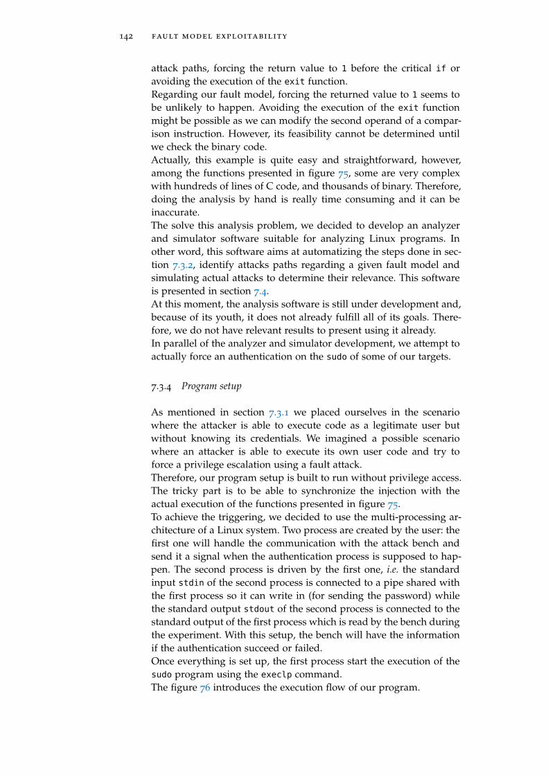
142 fault model exploitability
attack paths, forcing the return value to 1 before the critical if oravoiding the execution of the exit function.Regarding our fault model, forcing the returned value to 1 seems tobe unlikely to happen. Avoiding the execution of the exit functionmight be possible as we can modify the second operand of a compar-ison instruction. However, its feasibility cannot be determined untilwe check the binary code.Actually, this example is quite easy and straightforward, however,among the functions presented in figure 75, some are very complexwith hundreds of lines of C code, and thousands of binary. Therefore,doing the analysis by hand is really time consuming and it can beinaccurate.The solve this analysis problem, we decided to develop an analyzerand simulator software suitable for analyzing Linux programs. Inother word, this software aims at automatizing the steps done in sec-tion 7.3.2, identify attacks paths regarding a given fault model andsimulating actual attacks to determine their relevance. This softwareis presented in section 7.4.At this moment, the analysis software is still under development and,because of its youth, it does not already fulfill all of its goals. There-fore, we do not have relevant results to present using it already.In parallel of the analyzer and simulator development, we attempt toactually force an authentication on the sudo of some of our targets.
7.3.4 Program setup
As mentioned in section 7.3.1 we placed ourselves in the scenariowhere the attacker is able to execute code as a legitimate user butwithout knowing its credentials. We imagined a possible scenariowhere an attacker is able to execute its own user code and try toforce a privilege escalation using a fault attack.Therefore, our program setup is built to run without privilege access.The tricky part is to be able to synchronize the injection with theactual execution of the functions presented in figure 75.To achieve the triggering, we decided to use the multi-processing ar-chitecture of a Linux system. Two process are created by the user: thefirst one will handle the communication with the attack bench andsend it a signal when the authentication process is supposed to hap-pen. The second process is driven by the first one, i.e. the standardinput stdin of the second process is connected to a pipe shared withthe first process so it can write in (for sending the password) whilethe standard output stdout of the second process is connected to thestandard output of the first process which is read by the bench duringthe experiment. With this setup, the bench will have the informationif the authentication succeed or failed.Once everything is set up, the first process start the execution of thesudo program using the execlp command.The figure 76 introduces the execution flow of our program.

7.3 sudo authentication 143
Bench Send signal Wait trigger Perturb Wait response
Process 1 Wait signalSend (dummy)
passwordWait response Send response
Process 2 sudo ‘command’Wait
passwordVerify
passwordSend
responseE
Figure 76: Target program execution flow
This figure presents the general architecture of our setup. Thecommunication between the first process and the bench is donevia a trigger signal. On our target, we are able to write onthe IOs from the user land, using the /dev/gpiomem file onARM targets and using a network LED accessible using the/sys/class/leds/b43-phy0::radio/brightness file on Intel targets.As mentioned, the first process communicates with the second oneafter creating it using the fork function and redirect its standard in-puts and outputs using the pipe and dup2 functions as presented inlisting 7.11.
303 if(pipe(pc_fd) < 0)
304 return EXIT_FAILURE;
/* Some code... */
311 pid = fork();
/* Some code... */
315 /* Child process */
316 else if(pid == 0)
317 close(cp_fd[0]); /* Close the read end of the child to
parent pipe */→
318 dup2(cp_fd[1], STDOUT_FILENO); /* Redirect STDOUT to the
write end of the child to parent pipe */→
319 close(pc_fd[1]); /* Close the write end of the parent to
child pipe */→
320 dup2(pc_fd[0], STDIN_FILENO); /* Redirect STDIN to the
read end of the parent to child pipe */→
321 execlp("sudo", "sudo", "-S", "whoami", NULL);
322
Listing 7.11: C code for the child process in the sudo evaluation setup.
This code shows the connecting process of the standard input andoutput of the child to pipes. Also, one can see that the sudo programwill execute the whoami command. This command returns the username which is root in the case we have the root privileges (UID ==
0). However, any command can be used instead to realize a completeprivilege escalation.

144 fault model exploitability
Once the second process is set up, the first one can control it by writ-ing into the pipe connected to the standard input and reading fromthe one connected to the standard output as shown in listing 7.12.
325 close(cp_fd[1]); /* Close the write end of the child to
parent pipe */→
326 close(pc_fd[0]); /* Close the read end of the parent to
child pipe */→
/* Some code... */
356 write(pc_fd[1], "pwd\n", 4);
/* Some code... */
370 read(cp_fd[0], buf, BUFSIZE);
Listing 7.12: Part of the C code for the parent process communicating withthe child process.
With this setup, we fully automatize a user land application to controla process executing sudo while communicating to the attack benchusing IOs.However, we need to evaluate how relevant this setup is before tryingto do any attack using it.
7.3.5 Side channel analysis
To test our setup, we decided to do a side channel analysis. The goalis to determine if the trigger signal we are outputting to the bench isrelevant regarding the authentication process.As presented in figure 76, the trigger is raised up right after the pass-word is sent. According to the gdb trace presented in listing 7.9 theprompt message is display in the verify_user and sudo_pam_verify
functions. This means that the trigger rise up after them.We can conclude that, at most, the functions from libpam.so are ex-ecuted, then the dynamic linker load pam_unix.so and then its func-tions are executed before backing up the information about the suc-cess of the failure of the authentication and executing the commandor not.The figure 77 presents the EM activity of the CPU during both a failedand a succeed authentication.These traces were acquired on the BCM2711b0 (Raspberry Pi 4) target.The acquisition of these traces require to success the authentication,so we realized them on a mastered target. Therefore, an accessible de-vice is needed for this characterization. The blue signal correspondsto the EM activity and the orange signal corresponds to the triggersignal received by the bench.To obtained these traces, we placed the side channel probe at theposition X = 6.5mm and Y = 5.9mm regarding the BCM2711b0 layoutavailable in figure 60.

7.3 sudo authentication 145
0
25
50
75
100
125
150
175
Volta
ge (V
)
Succeed authenticationEM signalTrigger signal
0 1000 2000 3000 4000 5000 6000 7000 8000 9000 10000 11000 12000 13000 14000Time ( s)
0
25
50
75
100
125
150
175
Volta
ge (V
)
Failed authentication
Figure 77: EM activity of the CPU during a user authentication onBCM2711b0
Regarding the traces on figure 77, we can identify two activity areas.One constant in time and one time variable depending on the successor the failure of the authentication. At this point we can supposethat the first activity area corresponds to the load of the pam_unix.so
library in the memory while the second area matches with the hashcomparison.To confirm this hypothesis, we can check the compared hashes. In-deed, as shown in listing 7.9, the two hashes have a common pre-fix $6$hH.15uU5laaxuXHY$ which is added to the real password hashby the Linux kernel before the comparison. As this prefix is alwaysthe same, the strcmp never fail while comparing the first part of thehashes. Also, this prefix is 20B long while the compared hash (prefixincluded) are 106B long. Therefore, comparing two different hashesmust be five times faster than comparing the same hashes, if the firstcharacter after the prefix is different as it is the case in listing 7.9.Regarding the figure 77, we can see that in the case of a failed au-thentication, the second activity area lasts for around 400ms (from4500ms to 4900ms). While, in the case of a succeed authentication,the second activity area lasts for around 2200ms (from 4500ms to7700ms). As the ratio of the execution time of these areas (400/2200 =
0.182) is close to the ratio of identity between the hashes (20/106 =
0.189), we can consider that they are correlated and that we actuallyobserve the hash comparison. However, we cannot confirm more thishypothesis as it would require us to be able to forge a hash which par-tially match the real one. But as the hash algorithm is SHA512 (iden-tified by the $6$ identifier in the common prefix) obtaining hasheswhich partially collide require to brute force them. This is too muchtime consuming to actually doing it, for instance, we need to generate25610 = 280 passwords to have a collision with 10 common bytes.
7.3.6 Exploitation
Regarding our side channel analysis, we are confident that our setupable us to observe a relevant trigger regarding the sudo authentication

146 fault model exploitability
and in particular the hash comparison. However, we are limited to asub-part of the whole process execution because the trigger is raisedup just after the password is sent.Another strategy would have been to rise the trigger just before start-ing the sudo program. However, this would lead to a long executionwindow making it hard to attack.This is why we decided to stick with the first solution, as we canobserve the program behavior with a reasonable time window, wedecided to attack the authentication with a perturbation (laser onBCM2711b0 and EM on Intel Core i3). As we did not already fullyanalyzed the program, we sweep over the time window and observethe consequences.However, this method did not give us interesting results already. Thismight comes from the fact that, despite we have the smallest time win-dow possible, it remains large regarding the CPU frequency. Therefore,to have a not to long experiment we had to use a large step for thesweep and we therefore must have missed the interesting areas tofault.This large time window shows how important it is to analyze suchprogram. The goal is to reduce the interesting time window to accel-erate the sweeping process.
7.3.6.1 Enhancing existing attack
Another interesting way to evaluate a system is to enhance proofs ofconcept attacks to turn them into real attack.In [166], the authors successfully force two different hashes to be con-sidered as the same by the strcmp function used in the verify_pwd_-
hash function of the pam_unix.so file. Contrary to us, they target thesu program, which is close to the sudo program as it able to changethe user identity (and therefore its privilege level).However, to achieve this attack, the authors modified the libpam li-brary by adding a trigger in the libpam_misc module. As this addi-tion requires to have the root privilege, this attack is not a privilegeescalation but a proof of concept of the weakness of the strcmp func-tion against the instruction skip fault model. The attack consists inexiting the comparing loop of the strcmp function by skipping a cbz
instruction (Compare and Branch on Zero in ARM).Regarding this work and, using our attack setup and analysis, weshould be able to realize a real privilege escalation as we are able toidentify the strcmp function execution, with root privileges, using auser land trigger and side channels. However, we did not identifiedthe same fault model as theirs (instruction skip) and their target isnot clearly identified.Another enhancement would be to identify the strcmp function exe-cution with a pattern recognition method. Doing so, the attack wouldbe portable on any target leaking the library loading and strcmp exe-cution.

7.4 analysis tools 147
7.3.7 Conclusion on the forced authentication
In this section, we presented our work aiming at evaluating the userauthentication process of the sudo program. This program is an in-teresting example of a complete Linux program, it works with Linuxcredentials management and it involves shared libraries and the dy-namic linker in several ways.The variety of mechanisms involved in the execution of a Linux pro-gram and the important size of both the source code and the binarycode of the target program make an exhaustive analysis really timeconsuming. Therefore, we focused on determining the interestingparts of our program such as the pieces of code manipulating theinformation storing if the authentication succeed or failed.We have done this analysis by recompiling the target program withdebug symbols and using the gdb tool. This way, we were able toidentify the architecture of the sudo program regarding the user au-thentication. However, for a more precise analysis of the involvedfunctions, and due to the important size of both the code and thebinary, we need a more automatized tool.In parallel of the code analysis, we realized a software setup whichable to attack the sudo program from the user land and we analyzedit using side channels. This analysis gives us the information that weare able to have a trigger around the dynamic linker execution andthe hash comparison. However, we were not able to achieve an attackforcing the authentication due to our lack of precision regarding theimportant time window the program executes in. This highlights theneed of a tool that helps us to determine the interesting pieces of codeto fault and to time our perturbation with them.However, a recent work [166], successfully forced an authenticationon a modified libpam with an instruction skip fault model on thestrcmp function. As our setup does not need any root privilege andthat we are able to identify the strcmp execution via side channels, ifwe are able to realize instruction skips, we might be able to realize areal privilege escalation.Despite this would lead to a successful attack, it is only one identifiedattack path and there is a lot of work remaining to actually assess thesecurity of such program.
7.4 analysis tools
As we have seen in the above section, analyzing a Linux program is acomplex task due to its size and some kernel mechanisms involved inthe execution. Also, due to their large execution time, blindly sweepover the execution time to find an interesting moment to attack is avery time consuming step. Therefore, being able to simulate an attackregarding a fault model on a whole program will save a lot of time inthe evaluation of such programs.For these reasons, we decided to develop an analysis and fault sim-ulation tool which is adapted for Linux programs. This tool aims at
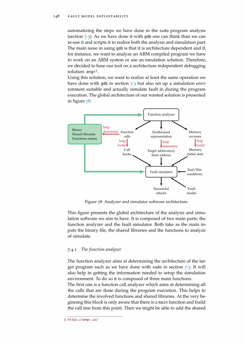
148 fault model exploitability
automatizing the steps we have done in the sudo program analysis(section 7.3). As we have done it with gdb one can think than we canre-use it and scripts it to realize both the analysis and simulation part.The main issue in using gdb is that it is architecture dependent and if,for instance, we want to analyze an ARM compiled program we haveto work on an ARM system or use an emulation solution. Therefore,we decided to base our tool on a architecture independent debuggingsolution: angr3.Using this solution, we want to realize at least the same operation wehave done with gdb in section 7.3 but also set up a simulation envi-ronment suitable and actually simulate fault in during the programexecution. The global architecture of our wanted solution is presentedin figure 78.
Function analyzer
Synthesizedrepresentation
Memoryaccesses
Functioncalls
Target address(es),Start address
helpdetermine
Callhooks
helpbuild
Memoryinitial state
helpbuild
Fault simulatorEnd/Winconditions
Faultmodel
BinaryShared librariesFunctions names
helpdetermine
Successfulattacks
Figure 78: Analyzer and simulator software architecture.
This figure presents the global architecture of the analysis and simu-lation software we aim to have. It is composed of two main parts: thefunction analyzer and the fault simulator. Both take as the main in-puts the binary file, the shared libraries and the functions to analyzeof simulate.
7.4.1 The function analyzer
The function analyzer aims at determining the architecture of the tar-get program such as we have done with sudo in section 7.3. It willalso help in getting the information needed to setup the simulationenvironment. To do so it is composed of three main functions.The first one is a function call analyzer which aims at determining allthe calls that are done during the program execution. This helps todetermine the involved functions and shared libraries. At the very be-ginning this block is only aware that there is a main function and buildthe call tree from this point. Then we might be able to add the shared
3 https://angr.io/

7.4 analysis tools 149
libraries and functions we want to analyze and so on. However, it isimportant to keep in mind that for the analysis to be done efficientlythe shared libraries have to be compiled with debug symbols. Other-wise the calls cannot be resolved. Regarding the simulation part, ithelps to determine the calls we want to hook during the simulation,this aims at reducing the actual simulated code and focus only on theinteresting part. Indeed, some functions such as error printing arenot needed to be correctly simulated and it is therefore interesting tohook them to fasten the simulation.The second function is a function printer. It aims at providing a syn-thesized but complete overview of a given function. This helps atunderstanding the architecture of a function and therefore determinethe interesting instructions to fault. This able us to avoid to test afault on all instructions of the program but only focus on interestingones. However, in the case of very large functions (like the sudoers_-
policy_main in sudoers.so), this tool is not efficient enough to pro-vide a view which is actually exploitable for determining interestinginstructions to fault by a human. Therefore, automatizing this stepwould give a huge added value to our software and is an interestingtopic to work on. This function summary also helps at identifying astart address for the simulation. Indeed, simulating the whole pro-gram is useless if we aim at targeting a precise piece of code andwould be really time consuming. Therefore, identifying the addresswhere to start the simulation is important. Doing so also imply the ne-cessity of given an initial state for the simulation environment as thesimulation will not start from the main function. The printing func-tion can display the disassembly in a shell as in figure 79 with arrowsfor the branch instructions and by coloring the basic blocs, in Tikz asin appendix D with also arrows for the branch instructions and basicblocs in actual blocs and in HTML4 with basic blocs in actual blocsand clickable links for branches with a highlight of the targeted basicbloc.The third function aims at determining all the memory accesses doneduring the program execution. This is useful to initialize the relevantparts of the simulation memory, in particular when we do not startthe program from the main function as suggested above.All the tools presented in this section are developed with Python3
and are based on the angr library which is itself based on capstone5
and unicorn6.
7.4.2 Fault simulator
The fault simulator aims at testing a program security by injectingfaults in it at runtime. The main issue about simulating a Linux pro-gram is the management of the shared libraries. However, angr man-
4 Live examples with sudoers_policy_check and sudoers_policy_main available athttps://thomas.trouchkine.com/demo/
5 http://www.capstone-engine.org/
6 https://www.unicorn-engine.org/docs/

150 fault model exploitability
Figure 79: sudoers_policy_check function partial disassembly printed in ashell.
age them smoothly as it automatically initialize a suitable memoryfor the program and able to hook the unresolved functions.However, as mentioned above in some cases, we do not want to startthe program execution from the start so we have to provide the targetaddress and modify the memory initialization. Actually, by defaultangr allocate a memory but set every address as UNINITIALIZED.Also, as we want to simulate fault injection, we need to inject faults.This is done via a fault generator. Currently, the fault generator canonly generates fault instructions. The reason is that we focused on de-veloping what we actually observed. The faulted instruction replacesthe actual instruction via a hook at the target address.The last things to configure in the fault simulator are the endingcondition and the winning condition. The ending condition is usefulwhen we do not want to wait for the program to be fully simulatedbut prematurely terminating it when we know that we can verify ifthe attack succeed or not, usually we simply check that we reacheda certain instruction (the return of a specific function for instance).The winning condition able the simulator to verify if the attack wassuccessful or not, if it is the case, it stores the fault, i.e. the fault in-
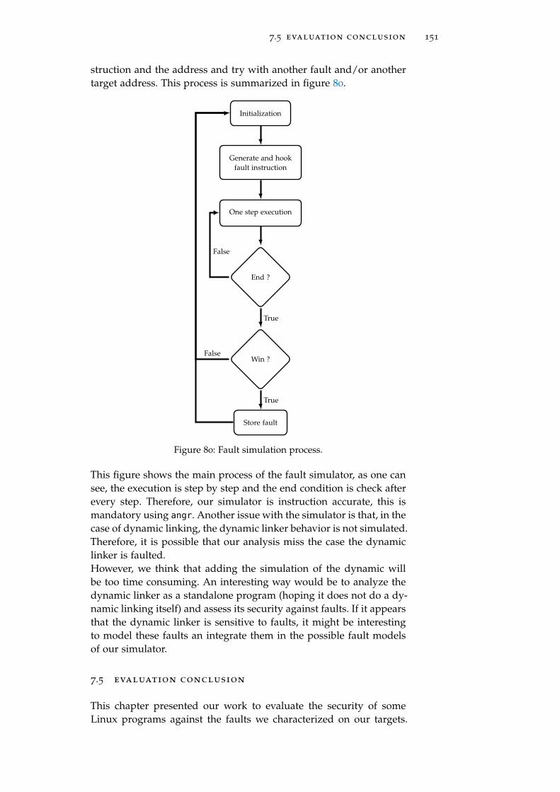
7.5 evaluation conclusion 151
struction and the address and try with another fault and/or anothertarget address. This process is summarized in figure 80.
Initialization
Generate and hookfault instruction
One step execution
End ?
Win ?
Store fault
False
True
True
False
Figure 80: Fault simulation process.
This figure shows the main process of the fault simulator, as one cansee, the execution is step by step and the end condition is check afterevery step. Therefore, our simulator is instruction accurate, this ismandatory using angr. Another issue with the simulator is that, in thecase of dynamic linking, the dynamic linker behavior is not simulated.Therefore, it is possible that our analysis miss the case the dynamiclinker is faulted.However, we think that adding the simulation of the dynamic willbe too time consuming. An interesting way would be to analyze thedynamic linker as a standalone program (hoping it does not do a dy-namic linking itself) and assess its security against faults. If it appearsthat the dynamic linker is sensitive to faults, it might be interestingto model these faults an integrate them in the possible fault modelsof our simulator.
7.5 evaluation conclusion
This chapter presented our work to evaluate the security of someLinux programs against the faults we characterized on our targets.

152 fault model exploitability
We managed to successfully realize a DFA on the OpenSSL implemen-tation of the AES and a PFA on our AES implemented on our RaspberryPi 3 bare metal setup. Regarding the sudo program we identified anexploitable attack path from a fault attack presented in ?? which issuitable with our program attack setup. However, the authors havea different fault model than the one we characterized, therefore, wedid not succeed to do the attack when we tried. But this is only oneattack path and many more might be available.The attack on the AES gives us the information that despite CPU op-timizations, it is still possible to synchronize a fault injection with aspecific moment of the program execution. However, the results weobserve does not match with a sequential execution of the AES. Re-garding the sudo program, our side channel analysis confirm that theparallel execution is negligible as we were able to observe the timingdifferences on the comparison of similar or different hashes in thestrcmp function.We also defined an analysis method for complex Linux programs likethe sudo one and we started to develop an software which aims at an-alyzing such programs but also simulate them while injecting faultsto assess their resilience against faults.This kind of software highlight many challenges as it aims at simu-lating a complex system with shared library and a dynamic linker.At the moment, we do not simulate the dynamic linker. We think thebest thing to do is to analyze it as a standalone software and assessits security against faults. Therefore, not considering it in the simula-tion will be relevant. Also, all shared libraries are not loaded duringthe simulation but some calls are simply hooked at runtime. Despitethis reduces the coverage of the simulation, it makes it faster than anexhaustive one. But to do so, we need to identify the relevant func-tions to actually simulate and the one we can hook, this is what theanalysis part of our software is designed for.

Part III
C O N C L U S I O N
This is how it ends.


8C O N C L U S I O N
During this thesis, we aim at providing elements that would help theevaluation of modern devices, also known as SoCs, against physicalattacks and in particular, perturbation attacks.In chapter 1 we presented the need of security evaluation in gen-eral and the special need regarding new technologies, in particularmobile devices. Indeed, these mobile devices propose a wide varietyof services, including sensitive ones such as identification, paymentand healthcare. Doing so, they slowly replace security oriented, ded-icated and evaluated devices, also known as SEs. Therefore, to matchnew usages and not reduce our security level, we need to be able toevaluated the security of these new devices.Because, we already evaluate SEs, we have a good idea on the existingphysical attacks. However, the differences between SEs and modernSoCs rise the question about the portability of the evaluation process.This is why we presented in chapter 2 the main differences betweenthese devices and we highlighted that modern SoCs have a more com-plex CPU than SEs, in many ways. More cores with more optimization,which also execute a more complex architecture.By considering this complexity, we developed a fault characterizationmethod we presented in chapter 5 and that we used in chapter 6
on three targets representing the available modern devices with twoARM and one Intel devices. This characterization work helped us todetermine that all the targets are faulted in the same way indepen-dently of the injection medium, here EM and laser perturbations, andindependently of their architecture. Despite, the exact fault modelmay vary from a target to another, we were able to modify the sec-ond operand of a target instruction on all of them. This gives us theinformation that these targets, and maybe many more, share a similarmechanism which behave in the same way to perturbations. This isinteresting in many ways, the first one is that if we are able to iden-tify the mechanism, we can propose a countermeasure and apply itto all the devices with these mechanism. However, this also meansthat if an attack using a fault on this mechanism works on a device,there is great chances that it works on another devices with the samemechanism.However, we did not focused on identifying the mechanism andproposing a countermeasure but we kept working on the evalua-tion of SoCs. Indeed, in the chapter 7 we focused on assessing theexploitability of the fault model we characterized. As we workedon the Linux ecosystem, we identified all the specific elements ofa program execution in the environment, in particular the dynamiclibraries, the dynamic linker and the asynchronous process execution.Despite these mechanisms, we were able to attack the AES algorithmin two different ways, one with the operand corruption fault model
155

156 conclusion
doing a DFA and one with a persistent corruption in the cache using aPFA. The DFA confirmed us that we are actually able to target a specificround of the AES, even in an asynchronous and time variable execu-tion environment while the PFA able to highlight that synchronizationissues may be avoided if a persistent fault is set in the memory sub-system of the device.The final evaluation we have done is on the sudo program. Our aimwas to evaluate the Linux authentication process regarding our faultmodel. However, the complexity and size of such program makesthe analysis of such software a tricky and time consuming businessrequiring debug tools, binary analysis and fault simulator software.However, as this is a new topic, there is no such tools available formodern devices. Therefore, we presented the analysis method andthe first development of tools which aim at easing the evaluation ofsuch software regarding fault attacks.Answering all these questions gave us a large but precise overviewof the requirements for evaluating a modern device. However, anddespite it is important, we did not discuss about specific to SoCs coun-termeasures in this work as it would be to time consuming regardingthe time available for a thesis.
identified research topics and future works
This work helped us to identify several relevant research topics andfuture works which would help the scientific community to keepworking on the SoC evaluation against perturbation attacks.
An interesting topic is the development of an open signal managerfor attack benchs. Indeed, as mentioned in section 6.1.1, analyzingthe signals coming from a DUT and being able to produce a relevanttrigger signal for synchronizing a perturbation with a moment ofthe target execution will be very helpful for the analysis of moderndevices. The main reason is that most of them, in particular smart-phones, are closed devices and producing an efficient trigger is atricky business. Pattern matching methods are known to be efficientbut their implementations remain under intellectual property. Anopen and public initiative on this topic would help researchers intesting and evaluating relevant attacks while increasing the repeata-bility of experiments on closed targets.
Regarding our characterization, as we identify similar fault modelson different targets using different injection mediums, it is importantto determine which mechanism is common to these targets, whyits perturbation induces an operand corruption on the executedinstructions. Also, regarding this fault model, an interesting topicwould be the development of a solution to protect instructionsagainst corruptions.

conclusion 157
From the software point of view, our work highlight the importanceof the dynamic linker in the execution of a program in the Linuxenvironment. An interesting topic would be to analyze the behaviorof this piece of code regarding perturbation attacks. Moreover,identifying security concerned pieces of code in the Linux kernel andpropose an analysis against faults and even countermeasure shouldbe an important research topic in the future.
Finally, the last interesting topic we identified is the development ofa tool which helps in the analysis of programs running in the Linuxenvironment against faults. Indeed, currently existing code analyzerswork on reduced pieces of code in a simple environment (limitedlinks and sequential execution).
scientific communication
International conferences
1. Thomas Trouchkine, Guillaume Bouffard, and Jessy Clediere.“Fault Injection Characterization on modern CPUs – From theISA to the Micro-Architecture.” In: WISTP 2019, Paris, France.2019
International journals
1. Thomas Trouchkine et al. “Electromagnetic Fault Injectionagainst a complex CPU, toward a new micro-architectural faultmodels.” In: Journal of Cryptographic Engineering (JCEN). 2020
National conferences
1. Thomas Trouchkine, Guillaume Bouffard, and Jessy Clediere.“EM Injection Vs. Modern CPU - Fault Characterization AndAES Differential Fault Analysis.” In: Comptatibilité électromagné-tique France 2020. 2020
Workshops
1. Thomas Trouchkine, Guillaume Bouffard, and Jessy Clediere.“Perturbation attack on modern CPUs, from the fault model tothe exploitation.” In: Journée thématique sur les attaques par injec-tion de fautes (JAIF). 2020
2. Guillaume Bouffard et al. “Radically secure computing.” In:SILM seminar 2020. 2020
3. Thomas Trouchkine et al. “Do not trust modern System-on-Chips.” In: PHISIC 2019. 2019

158 conclusion
4. Thomas Trouchkine et al. “Do not trust modern System onChip.” In: Journée thématique sur les attaques par injection de fautes(JAIF). 2019
5. Thomas Trouchkine. “EM fault injection on Raspberry Pi 3 andZedBoard.” In: GDR SoC2 research group. 2018
6. Thomas Trouchkine. “Problems and state of the art of faultsinjection on Systems on Chip.” In: PHISIC 2018. 2018
All the articles and slides are available on my website at https://
thomas.trouchkine.com/publications/
open sourced projects
• Plotter python package (https://plotter-doc.xyz/)

Part IV
A P P E N D I X


AB C M 2 8 3 7 M A P S P E R FA U LT M O D E L
1413121110987654321Position (mm)
0
1
2
3
4
5
6
7
8
9
10
11
12
13
Position(m
m)
0
1
2
3
4
5
6
7
8
9
10
11
12
Number
offaultsper
position
(a) Unknown fault model
1413121110987654321Position (mm)
0
1
2
3
4
5
6
7
8
9
10
11
12
13
Position(m
m)
0
1
2
3
4
5
Number
offaultsper
position
(b) “Or with other obs”
1413121110987654321Position (mm)
0
1
2
3
4
5
6
7
8
9
10
11
12
13
Position(m
m)
0
1
2
3
4
5
6
7
8
9
10
Number
offaultsper
position
(c) “Other obs value”
1413121110987654321Position (mm)
0
1
2
3
4
5
6
7
8
9
10
11
12
13
Position(m
m)
0
1
2
Number
offaultsper
position
(d) “Or between two other obs”
1413121110987654321Position (mm)
0
1
2
3
4
5
6
7
8
9
10
11
12
13
Position(m
m)
0
1
Number
offaultsper
position
(e) “Bit reset”
1413121110987654321Position (mm)
0
1
2
3
4
5
6
7
8
9
10
11
12
13
Position(m
m)
0
1
Number
offaultsper
position
(f) “Bit set”
1413121110987654321Position (mm)
0
1
2
3
4
5
6
7
8
9
10
11
12
13
Position(m
m)
0
1
2
Number
offaultsper
position
(g) “Bit flip”
Figure 81: BCM2837 hot spots leading to the different observed fault models
161

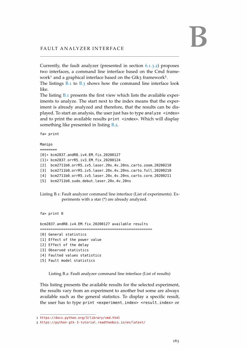
BFA U LT A N A LY Z E R I N T E R FA C E
Currently, the fault analyzer (presented in section 6.1.3.2) proposestwo interfaces, a command line interface based on the Cmd frame-work1 and a graphical interface based on the Gtk3 framework2.The listings B.1 to B.3 shows how the command line interface looklike.The listing B.1 presents the first view which lists the available exper-iments to analyze. The start next to the index means that the exper-iment is already analyzed and therefore, that the results can be dis-played. To start an analysis, the user just has to type analyze <index>
and to print the available results print <index>. Which will displaysomething like presented in listing B.2.
fa> print
Manips
========
[0]* bcm2837_andR8_iv4_EM_fix_20200127
[1]* bcm2837_orrR5_iv3_EM_fix_20200124
[2] bcm2711b0_orrR5_iv5_laser_20x_4v_20ns_carto_zoom_20200210
[3] bcm2711b0_orrR5_iv5_laser_20x_4v_20ns_carto_full_20200210
[4] bcm2711b0_orrR5_iv5_laser_20x_4v_20ns_carto_core_20200211
[5] bcm2711b0_sudo_debut_laser_20x_4v_20ns
Listing B.1: Fault analyzer command line interface (List of experiments). Ex-periments with a star (*) are already analyzed.
fa> print 0
bcm2837_andR8_iv4_EM_fix_20200127 available results
=====================================================
[0] General statistics
[1] Effect of the power value
[2] Effect of the delay
[3] Observed statistics
[4] Faulted values statistics
[5] Fault model statistics
Listing B.2: Fault analyzer command line interface (List of results)
This listing presents the available results for the selected experiment,the results vary from an experiment to another but some are alwaysavailable such as the general statistics. To display a specific result,the user has to type print <experiment_index> <result_index> or
1 https://docs.python.org/3/library/cmd.html
2 https://python-gtk-3-tutorial.readthedocs.io/en/latest/
163
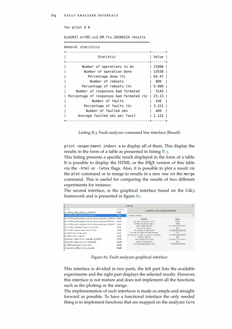
164 fault analyzer interface
fa> print 0 0
bcm2837_orrR5_iv3_EM_fix_20200124 results
===========================================
General statistics
+------------------------------------------+-------+
| Statistic | Value |
+------------------------------------------+-------+
| Number of operations to do | 21000 |
| Number of operation done | 13538 |
| Percentage done (%) | 64.47 |
| Number of reboots | 800 |
| Percentage of reboots (%) | 5.909 |
| Number of responses bad formated | 3145 |
| Percentage of responses bad formated (%) | 23.23 |
| Number of faults | 436 |
| Percentage of faults (%) | 3.221 |
| Number of faulted obs | 489 |
| Average faulted obs per fault | 1.122 |
+------------------------------------------+-------+
Listing B.3: Fault analyzer command line interface (Result)
print <experiment_index> a to display all of them. This display theresults in the form of a table as presented in listing B.3.This listing presents a specific result displayed in the form of a table.It is possible to display the HTML or the LATEX version of this tablevia the -html or -latex flags. Also, it is possible to plot a result viathe plot command or to merge to results in a new one via the merge
command. This is useful for comparing the results of two differentexperiments for instance.The second interface, is the graphical interface based on the Gtk3
framework and is presented in figure 82.
Figure 82: Fault analyzer graphical interface
This interface is divided in two parts, the left part lists the availableexperiments and the right part displays the selected results. However,this interface is not mature and does not implement all the functionssuch as the plotting or the merge.The implementation of such interfaces is made as simple and straight-forward as possible. To have a functional interface the only neededthing is to implement functions that are mapped on the analyzer Core

fault analyzer interface 165
functions, such as print, plot, analyze, etc. Then the interface mustsimply get the Core class as argument such as presented in listing B.4.
1 if __name__ == "__main__":
2 c = Core(**CONFIG)
3
4 # Argument parsing...
5
6 if args.gui:
7 interface = Gtk3FaultAnalyzer(c)
8 interface.start_interface()
9 else:
10 interface = Cmdline(c)
11 interface.cmdloop()
Listing B.4: main of the fault analyzer


CG D B A N A LY S I S O F SUDO W I T H D E B U G S Y M B O L S
1 Breakpoint 1, __strcmp_avx2 () at
../sysdeps/x86_64/multiarch/strcmp-avx2.S:92→
2 92 ../sysdeps/x86_64/multiarch/strcmp-avx2.S: No such file or
directory.→
3 0x5637b173b050: "$6$hH.15uU5laaxuXHY$wtSOcCKWmY1JmyY2CWlVs/8ixyO ⌋
N36ZxQV2RpMJkITzqkIM18lyXNMICoYNIVDeUVXqH0Fs390nl6Lw8m5ArZ0"→
4 0x5637b173a200: "$6$hH.15uU5laaxuXHY$4b7acwY3u21L9Wd8TxQeCIkpmas ⌋
NufgDzIrScjXreP8oFQA4c.0nZmcYJB2zf5p6rDvPdBC0Fo6JWvquBKaVc."→
5 #0 __strcmp_avx2 () at ../sysdeps/x86_64/multiarch/strcmp-avx2.S:92
6 #1 0x00007fb956a006a0 in verify_pwd_hash (p=0x0, hash=0x5637b173a200
"$6$hH.15uU5laaxuXHY$4b7acwY3u21L9Wd8TxQeCIkpmasNufgDzIrScjXreP8oFQ ⌋
A4c.0nZmcYJB2zf5p6rDvPdBC0Fo6JWvquBKaVc.", nullok=0x0) at
passverify.c:124
→
→
→
7 #2 0x00007fb956a00050 in _unix_verify_password (pamh=0x5637b173fd30,
name=0x5637b173fed0 "toto", p=0x5637b173aad0 "", ctrl=0x40800400)
at support.c:792
→
→
8 #3 0x00007fb9569fc6fb in pam_sm_authenticate (pamh=0x5637b173fd30,
flags=0x8000, argc=0x1, argv=0x5637b1734620) at pam_unix_auth.c:177→
9 #4 0x00007fb956a1c024 in _pam_dispatch_aux (pamh=0x5637b173fd30,
flags=0x8000, h=0x5637b173c980, resumed=PAM_FALSE,
use_cached_chain=0x0) at pam_dispatch.c:110
→
→
10 #5 0x00007fb956a1c62c in _pam_dispatch (pamh=0x5637b173fd30,
flags=0x8000, choice=0x1) at pam_dispatch.c:411→
11 #6 0x00007fb956a1b68b in pam_authenticate (pamh=0x5637b173fd30,
flags=0x8000) at pam_auth.c:34→
12 #7 0x00007fb956a351f9 in sudo_pam_verify (pw=0x5637b1731318,
prompt=0x5637b1740f10 "[sudo] password for toto: ",
auth=0x7fb956a94220 <auth_switch>, callback=0x7fff76368d50) at
../../../plugins/sudoers/auth/pam.c:187
→
→
→
13 #8 0x00007fb956a3477e in verify_user (pw=0x5637b1731318,
prompt=0x5637b1740f10 "[sudo] password for toto: ", validated=0x2,
callback=0x7fff76368d50) at
../../../plugins/sudoers/auth/sudo_auth.c:328
→
→
→
14 #9 0x00007fb956a36a76 in check_user_interactive (validated=0x2,
mode=0x1, auth_pw=0x5637b1731318) at
../../../plugins/sudoers/check.c:153
→
→
15 #10 0x00007fb956a36d01 in check_user (validated=0x2, mode=0x1) at
../../../plugins/sudoers/check.c:223→
16 #11 0x00007fb956a5356c in sudoers_policy_main (argc=0x1,
argv=0x7fff76369230, pwflag=0x0, env_add=0x0, verbose=0x0,
closure=0x7fff76368ef0) at ../../../plugins/sudoers/sudoers.c:388
→
→
17 #12 0x00007fb956a4e516 in sudoers_policy_check (argc=0x1,
argv=0x7fff76369230, env_add=0x0, command_infop=0x7fff76368fd8,
argv_out=0x7fff76368fe0, user_env_out=0x7fff76368fe8) at
../../../plugins/sudoers/policy.c:866
→
→
→
18 #13 0x00005637b0270d5d in policy_check (plugin=0x5637b0285580
<policy_plugin>, argc=0x1, argv=0x7fff76369230, env_add=0x0,
command_info=0x7fff76368fd8, argv_out=0x7fff76368fe0,
user_env_out=0x7fff76368fe8) at ../../src/sudo.c:1162
→
→
→
19 #14 0x00005637b026c753 in main (argc=0x2, argv=0x7fff76369228,
envp=0x7fff76369240) at ../../src/sudo.c:250→
Listing C.1: gdb output of a strcmp call comparing two hashes with librariescompiled with debug symbols.
167


DSUDOERS_POLICY_CHECK() D I S A S S E M B LY
0x419274: push r4, r5, r6, r7, r8, sb, sl, fp, lr
0x419278: mov sl, r1
0x41927c: ldr r4, [pc, #0x14c]
0x419280: ldr r5, [pc, #0x14c]
0x419284: add r4, pc, r4
0x419288: ldr lr, [pc, #0x148]
0x41928c: ldr r5, [r4, r5]
0x419290: sub sp, sp, #0x24
0x419294: mov fp, r2
0x419298: ldr r1, [r5]
0x41929c: str r5, [sp, #0xc]
0x4192a0: str r1, [sp, #0x1c]
0x4192a4: ldr r2, [r4, lr]
0x4192a8: ldr ip, [pc, #0x12c]
0x4192ac: ldr r1, [pc, #0x12c]
0x4192b0: ldr r5, [r2, #0x38]
0x4192b4: add ip, pc, ip
0x4192b8: mov r6, r3
0x4192bc: mov sb, r0
0x4192c0: ldr r2, [pc, #0x11c]
0x4192c4: add r0, ip, #0x70
0x4192c8: mov r3, r5
0x4192cc: add r1, pc, r1
0x4192d0: ldr r8, [sp, #0x48]
0x4192d4: ldr r7, [sp, #0x4c]
0x4192d8: bl sudo_debug_enter_v1 @ 0x40376c
0x4192dc: ldr r3, [pc, #0x104]
0x4192e0: mov r1, sl
0x4192e4: mov r0, sb
0x4192e8: ldr r2, [r4, r3]
0x4192ec: str r6, [sp, #0x18]
0x4192f0: str r8, [sp, #0x10]
0x4192f4: ldr r3, [r2]
0x4192f8: str r7, [sp, #0x14]
0x4192fc: tst r3, #2
0x419300: orreq r3, r3, #1
0x419304: streq r3, [r2]
0x419308: add r2, sp, #0x10
0x41930c: str r2, [sp, #4]
0x419310: mov r2, #0
0x419314: mov r3, fp
0x419318: str r2, [sp]
0x41931c: bl sudoers_policy_main @ 0x42029c
0x419320: cmp r0, #1
0x419324: mov r6, r0
0x419328: beq #0x419370
0x41932c: ldr r0, [pc, #0xb8]
0x419330: ldr r1, [pc, #0xb8]
0x419334: add r0, pc, r0
0x419338: mov r3, r5
0x41933c: add r0, r0, #0x70
0x419340: ldr r2, [pc, #0xac]
0x419344: str r6, [sp]
0x419348: add r1, pc, r1
0x41934c: bl sudo_debug_exit_int_v1 @ 0x403f88
0x419350: ldr r3, [sp, #0xc]
0x419354: ldr r2, [sp, #0x1c]
0x419358: mov r0, r6
0x41935c: ldr r3, [r3]
0x419360: cmp r2, r3
0x419364: bne #0x4193cc
0x419368: add sp, sp, #0x24
0x41936c: pop r4, r5, r6, r7, r8, sb, sl, fp, pc
0x419370: ldr r3, [pc, #0x80]
0x419374: ldr r2, [pc, #0x80]
0x419378: add r3, pc, r3
0x41937c: ldr r3, [r3]
0x419380: cmp r3, r2
0x419384: bls #0x41932c
0x419388: ldr r3, [pc, #0x70]
0x41938c: ldr r3, [r4, r3]
0x419390: ldr r2, [r3, #0x82c]
0x419394: cmp r2, #0
0x419398: bne #0x41932c
0x41939c: ldr r2, [r3, #0x848]
0x4193a0: cmp r2, #0
0x4193a4: bne #0x41932c
0x4193a8: ldr r3, [r3, #0x880]
0x4193ac: cmp r3, #0
0x4193b0: bne #0x41932c
0x4193b4: bl sudo_auth_needs_end_session @ 0x40480c
0x4193b8: cmp r0, #0
0x4193bc: ldreq r3, [pc, #0x40]
0x4193c0: ldreq r3, [r4, r3]
0x4193c4: streq r0, [r3, #0xc]
0x4193c8: b #0x41932c
0x4193cc: bl __stack_chk_fail @ 0x403898
Figure 83: sudoers_policy_check() Tikz disassembly.
169

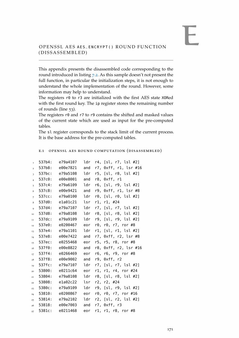
EO P E N S S L A E S AES_ENCRYPT() R O U N D F U N C T I O N( D I S S A S S E M B L E D )
This appendix presents the disassembled code corresponding to theround introduced in listing 7.2. As this sample doesn’t not present thefull function, in particular the initialization steps, it is not enough tounderstand the whole implementation of the round. However, someinformation may help to understand.The registers r0 to r3 are initialized with the first AES state XORedwith the first round key. The ip register stores the remaining numberof rounds (line 53).The registers r0 and r7 to r9 contains the shifted and masked valuesof the current state which are used as input for the pre-computedtables.The sl register corresponds to the stack limit of the current process.It is the base address for the pre-computed tables.
e.1 openssl aes round computation (disassembled)
1 537b4: e79a4107 ldr r4, [sl, r7, lsl #2]
2 537b8: e00e7821 and r7, 0xff, r1, lsr #16
3 537bc: e79a5108 ldr r5, [sl, r8, lsl #2]
4 537c0: e00e8001 and r8, 0xff, r1
5 537c4: e79a6109 ldr r6, [sl, r9, lsl #2]
6 537c8: e00e9421 and r9, 0xff, r1, lsr #8
7 537cc: e79a0100 ldr r0, [sl, r0, lsl #2]
8 537d0: e1a01c21 lsr r1, r1, #24
9 537d4: e79a7107 ldr r7, [sl, r7, lsl #2]
10 537d8: e79a8108 ldr r8, [sl, r8, lsl #2]
11 537dc: e79a9109 ldr r9, [sl, r9, lsl #2]
12 537e0: e0200467 eor r0, r0, r7, ror #8
13 537e4: e79a1101 ldr r1, [sl, r1, lsl #2]
14 537e8: e00e7422 and r7, 0xff, r2, lsr #8
15 537ec: e0255468 eor r5, r5, r8, ror #8
16 537f0: e00e8822 and r8, 0xff, r2, lsr #16
17 537f4: e0266469 eor r6, r6, r9, ror #8
18 537f8: e00e9002 and r9, 0xff, r2
19 537fc: e79a7107 ldr r7, [sl, r7, lsl #2]
20 53800: e0211c64 eor r1, r1, r4, ror #24
21 53804: e79a8108 ldr r8, [sl, r8, lsl #2]
22 53808: e1a02c22 lsr r2, r2, #24
23 5380c: e79a9109 ldr r9, [sl, r9, lsl #2]
24 53810: e0200867 eor r0, r0, r7, ror #16
25 53814: e79a2102 ldr r2, [sl, r2, lsl #2]
26 53818: e00e7003 and r7, 0xff, r3
27 5381c: e0211468 eor r1, r1, r8, ror #8
171

172 openssl aes aes_encrypt() round function (dissassembled)
28 53820: e00e8423 and r8, 0xff, r3, lsr #8
29 53824: e0266869 eor r6, r6, r9, ror #16
30 53828: e00e9823 and r9, 0xff, r3, lsr #16
31 5382c: e79a7107 ldr r7, [sl, r7, lsl #2]
32 53830: e0222865 eor r2, r2, r5, ror #16
33 53834: e79a8108 ldr r8, [sl, r8, lsl #2]
34 53838: e1a03c23 lsr r3, r3, #24
35 5383c: e79a9109 ldr r9, [sl, r9, lsl #2]
36 53840: e0200c67 eor r0, r0, r7, ror #24
37 53844: e49b7010 ldr r7, [fp], #16
38 53848: e0211868 eor r1, r1, r8, ror #16
39 5384c: e79a3103 ldr r3, [sl, r3, lsl #2]
40 53850: e0222469 eor r2, r2, r9, ror #8
41 53854: e51b400c ldr r4, [fp, #-12]
42 53858: e0233466 eor r3, r3, r6, ror #8
43 5385c: e51b5008 ldr r5, [fp, #-8]
44 53860: e0200007 eor r0, r0, r7
45 53864: e51b6004 ldr r6, [fp, #-4]
46 53868: e00e7000 and r7, 0xff, r0
47 5386c: e0211004 eor r1, r1, r4
48 53870: e00e8420 and r8, 0xff, r0, lsr #8
49 53874: e0222005 eor r2, r2, r5
50 53878: e00e9820 and r9, 0xff, r0, lsr #16
51 5387c: e0233006 eor r3, r3, r6
52 53880: e1a00c20 lsr r0, r0, #24
53 53884: e25cc001 subs ip, ip, #1
54 53888: 1affffc9 bne 537b4 <_armv4_AES_encrypt+0x34>

B I B L I O G R A P H Y
[1] Keith Mayes and Konstantinos Markantonakis. “Smart Cards,Tokens, Security and Applications.” In: Springer InternationalPublishing, 2017. isbn: 9783319505008.
[2] JavaCard Specification. 2020. url: https://www.oracle.com/java/technologies/javacard-specs-downloads.html.
[3] Moritz Lipp et al. “Meltdown.” In: meltdownattack.com (2018).url: https://meltdownattack.com/meltdown.pdf.
[4] Paul Kocher et al. “Spectre Attacks: Exploiting SpeculativeExecution.” In: meltdownattack.com (2018). url: https : / /
spectreattack.com/spectre.pdf.
[5] R. M. Tomasulo. “An Efficient Algorithm for Exploiting Multi-ple Arithmetic Units.” In: IBM Journal of Research and Develop-ment 11.1 (1967), pp. 25–33.
[6] Eric Brier, Christophe Clavier, and Francis Olivier. “Correla-tion Power Analysis with a Leakage Model.” In: CryptographicHardware and Embedded Systems - CHES 2004: 6th InternationalWorkshop Cambridge, MA, USA, August 11-13, 2004. Proceedings.Ed. by Marc Joye and Jean-Jacques Quisquater. Vol. 3156. Lec-ture Notes in Computer Science. Springer, 2004, pp. 16–29.doi: 10.1007/978-3-540-28632-5\_2. url: https://doi.org/10.1007/978-3-540-28632-5\_2.
[7] Paul C. Kocher. “Timing Attacks on Implementations of Diffie-Hellman, RSA, DSS, and Other Systems.” In: Advances in Cryp-tology - CRYPTO ’96, 16th Annual International Cryptology Con-ference, Santa Barbara, California, USA, August 18-22, 1996, Pro-ceedings. Ed. by Neal Koblitz. Vol. 1109. Lecture Notes in Com-puter Science. Springer, 1996, pp. 104–113. doi: 10.1007/3-540-68697-5\_9. url: https://doi.org/10.1007/3-540-68697-5\_9.
[8] Daniel Moghimi et al. “TPM-FAIL: TPM meets Timing and Lat-tice Attacks.” In: 29th USENIX Security Symposium (USENIXSecurity 20). Boston, MA: USENIX Association, Aug. 2020. url:https://www.usenix.org/conference/usenixsecurity20/
presentation/moghimi.
[9] Gildas Avoine and Loïc Ferreira. “Attacking GlobalPlatformSCP02-compliant Smart Cards Using a Padding Oracle At-tack.” In: IACR Trans. Cryptogr. Hardw. Embed. Syst. 2018.2(2018), pp. 149–170. doi: 10.13154/tches.v2018.i2.149-170.url: https://doi.org/10.13154/tches.v2018.i2.149-170.
[10] Andrew Kwong et al. “RAMBleed: Reading Bits in MemoryWithout Accessing Them.” In: 41st IEEE Symposium on Securityand Privacy (S&P). 2020.
173
174 bibliography
[11] Michael Schwarz et al. “ZombieLoad: Cross-Privilege-Boundary Data Sampling.” In: Proceedings of the 2019 ACMSIGSAC Conference on Computer and Communications Security,CCS 2019, London, UK, November 11-15, 2019. Ed. by LorenzoCavallaro et al. ACM, 2019, pp. 753–768. doi: 10 . 1145 /
3319535.3354252. url: https://doi.org/10.1145/3319535.3354252.
[12] Jo Van Bulck et al. “Foreshadow: Extracting the Keys tothe Intel SGX Kingdom with Transient Out-of-Order Execu-tion.” In: 27th USENIX Security Symposium, USENIX Security2018, Baltimore, MD, USA, August 15-17, 2018. Ed. by WilliamEnck and Adrienne Porter Felt. USENIX Association, 2018,pp. 991–1008. url: https://www.usenix.org/conference/usenixsecurity18/presentation/bulck.
[13] Paul C. Kocher, Joshua Jaffe, and Benjamin Jun. “Differen-tial Power Analysis.” In: Advances in Cryptology - CRYPTO’99, 19th Annual International Cryptology Conference, Santa Bar-bara, California, USA, August 15-19, 1999, Proceedings. Ed. byMichael J. Wiener. Vol. 1666. Lecture Notes in Computer Sci-ence. Springer, 1999, pp. 388–397. doi: 10.1007/3-540-48405-1\_25. url: https://doi.org/10.1007/3-540-48405-1\_25.
[14] Suresh Chari, Josyula R. Rao, and Pankaj Rohatgi. “Tem-plate Attacks.” In: Cryptographic Hardware and Embedded Sys-tems - CHES 2002, 4th International Workshop, Redwood Shores,CA, USA, August 13-15, 2002, Revised Papers. Ed. by BurtonS. Kaliski Jr., Çetin Kaya Koç, and Christof Paar. Vol. 2523.Lecture Notes in Computer Science. Springer, 2002, pp. 13–28.doi: 10.1007/3-540-36400-5\_3. url: https://doi.org/10.1007/3-540-36400-5\_3.
[15] David Oswald and Christof Paar. “Breaking Mifare DESFireMF3ICD40: Power Analysis and Templates in the Real World.”In: Cryptographic Hardware and Embedded Systems - CHES 2011 -13th International Workshop, Nara, Japan, September 28 - October1, 2011. Proceedings. Ed. by Bart Preneel and Tsuyoshi Takagi.Vol. 6917. Lecture Notes in Computer Science. Springer, 2011,pp. 207–222. doi: 10.1007/978- 3- 642- 23951- 9\_14. url:https://doi.org/10.1007/978-3-642-23951-9\_14.
[16] Timo Kasper, David Oswald, and Christof Paar. “EM Side-Channel Attacks on Commercial Contactless Smartcards Us-ing Low-Cost Equipment.” In: Information Security Applications,10th International Workshop, WISA 2009, Busan, Korea, August25-27, 2009, Revised Selected Papers. Ed. by Heung Youl Youmand Moti Yung. Vol. 5932. Lecture Notes in Computer Science.Springer, 2009, pp. 79–93. doi: 10.1007/978-3-642-10838-9\_7. url: https://doi.org/10.1007/978-3-642-10838-9\_7.
[17] Daniel Genkin et al. “ECDSA Key Extraction from Mobile De-vices via Nonintrusive Physical Side Channels.” In: IACR Cryp-

bibliography 175
tol. ePrint Arch. 2016 (2016), p. 230. url: http://eprint.iacr.org/2016/230.
[18] Eyal Ronen et al. “IoT Goes Nuclear: Creating a ZigBee ChainReaction.” In: IACR Cryptol. ePrint Arch. 2016 (2016), p. 1047.url: http://eprint.iacr.org/2016/1047.
[19] Benedikt Gierlichs, Lejla Batina, and Pim Tuyls. “Mutual Infor-mation Analysis - A Universal Differential Side-Channel At-tack.” In: IACR Cryptol. ePrint Arch. 2007 (2007), p. 198. url:http://eprint.iacr.org/2007/198.
[20] Guillaume Dabosville, Julien Doget, and Emmanuel Prouff.“A New Second-Order Side Channel Attack Based on LinearRegression.” In: IEEE Trans. Computers 62.8 (2013), pp. 1629–1640. doi: 10.1109/TC.2012.112. url: https://doi.org/10.1109/TC.2012.112.
[21] Houssem Maghrebi, Thibault Portigliatti, and EmmanuelProuff. “Breaking Cryptographic Implementations UsingDeep Learning Techniques.” In: Security, Privacy, and AppliedCryptography Engineering - 6th International Conference, SPACE2016, Hyderabad, India, December 14-18, 2016, Proceedings. Ed.by Claude Carlet, M. Anwar Hasan, and Vishal Saraswat.Vol. 10076. Lecture Notes in Computer Science. Springer, 2016,pp. 3–26. doi: 10.1007/978-3-319-49445-6\_1. url: https://doi.org/10.1007/978-3-319-49445-6\_1.
[22] Mathieu Carbone et al. “Deep Learning to Evaluate SecureRSA Implementations.” In: IACR Cryptol. ePrint Arch. 2019
(2019), p. 54. url: https://eprint.iacr.org/2019/054.
[23] A Hacker Guide To Deep Learning Based Side Channel Attacks.https://elie.net/talk/a-hackerguide-to-deep-learning-
based-side-channel-attacks/. Accessed: 2020-06-11.
[24] Diego F. Aranha et al. LadderLeak: Breaking ECDSA With LessThan One Bit Of Nonce Leakage. Cryptology ePrint Archive, Re-port 2020/615. https://eprint.iacr.org/2020/615. 2020.
[25] Peter Pessl et al. “DRAMA: Exploiting DRAM Addressingfor Cross-CPU Attacks.” In: 25th USENIX Security Sympo-sium, USENIX Security 16, Austin, TX, USA, August 10-12,2016. Ed. by Thorsten Holz and Stefan Savage. USENIX As-sociation, 2016, pp. 565–581. url: https : / / www . usenix .
org / conference / usenixsecurity16 / technical - sessions /
presentation/pessl.
[26] Clémentine Maurice et al. “Hello from the Other Side: SSHover Robust Cache Covert Channels in the Cloud.” In: 24th An-nual Network and Distributed System Security Symposium, NDSS2017, San Diego, California, USA, February 26 - March 1, 2017.The Internet Society, 2017. url: https://www.ndss-symposium.org/ndss2017/ndss- 2017- programme/hello- other- side-
ssh-over-robust-cache-covert-channels-cloud/.

176 bibliography
[27] Berk Gülmezoglu et al. “A Faster and More RealisticFlush+Reload Attack on AES.” In: Constructive Side-ChannelAnalysis and Secure Design - 6th International Workshop,COSADE 2015, Berlin, Germany, April 13-14, 2015. Revised Se-lected Papers. Ed. by Stefan Mangard and Axel Y. Poschmann.Vol. 9064. Lecture Notes in Computer Science. Springer, 2015,pp. 111–126. doi: 10 . 1007 / 978 - 3 - 319 - 21476 - 4 \ _8. url:https://doi.org/10.1007/978-3-319-21476-4\_8.
[28] Project Zero team. Reading privileged memory with a side-channel.Accessed: 2020-06-14. 2018. url: https://googleprojectzero.blogspot . co . uk / 2018 / 01 / reading - privileged - memory -
with-side.html.
[29] Robert M Tomasulo. “An efficient algorithm for exploitingmultiple arithmetic units.” In: IBM Journal of research and De-velopment 11.1 (1967), pp. 25–33.
[30] Saad Islam et al. “SPOILER: Speculative Load Hazards BoostRowhammer and Cache Attacks.” In: 28th USENIX SecuritySymposium, USENIX Security 2019, Santa Clara, CA, USA, Au-gust 14-16, 2019. Ed. by Nadia Heninger and Patrick Traynor.USENIX Association, 2019, pp. 621–637. url: https://www.usenix.org/conference/usenixsecurity19/presentation/
islam.
[31] Giorgi Maisuradze and Christian Rossow. “ret2spec: Specula-tive Execution Using Return Stack Buffers.” In: Proceedings ofthe 2018 ACM SIGSAC Conference on Computer and Communi-cations Security, CCS 2018, Toronto, ON, Canada, October 15-19,2018. Ed. by David Lie et al. ACM, 2018, pp. 2109–2122. doi:10.1145/3243734.3243761. url: https://doi.org/10.1145/3243734.3243761.
[32] Daniel Gruss et al. “Prefetch Side-Channel Attacks: Bypass-ing SMAP and Kernel ASLR.” In: Proceedings of the 2016 ACMSIGSAC Conference on Computer and Communications Security,Vienna, Austria, October 24-28, 2016. Ed. by Edgar R. Weippl etal. ACM, 2016, pp. 368–379. doi: 10.1145/2976749.2978356.url: https://doi.org/10.1145/2976749.2978356.
[33] Michael Schwarz et al. “NetSpectre: Read Arbitrary Memoryover Network.” In: Computer Security - ESORICS 2019 - 24thEuropean Symposium on Research in Computer Security, Luxem-bourg, September 23-27, 2019, Proceedings, Part I. Ed. by KazueSako, Steve Schneider, and Peter Y. A. Ryan. Vol. 11735. Lec-ture Notes in Computer Science. Springer, 2019, pp. 279–299.doi: 10.1007/978-3-030-29959-0\_14. url: https://doi.org/10.1007/978-3-030-29959-0\_14.
[34] Matthieu Rivain, Emmanuelle Dottax, and Emmanuel Prouff.“Block Ciphers Implementations Provably Secure Against Sec-ond Order Side Channel Analysis.” In: Fast Software Encryption,15th International Workshop, FSE 2008, Lausanne, Switzerland,February 10-13, 2008, Revised Selected Papers. Ed. by Kaisa Ny-

bibliography 177
berg. Vol. 5086. Lecture Notes in Computer Science. Springer,2008, pp. 127–143. doi: 10.1007/978-3-540-71039-4\_8. url:https://doi.org/10.1007/978-3-540-71039-4\_8.
[35] Rajat Subhra Chakraborty and Swarup Bhunia. “Hardwareprotection and authentication through netlist level obfusca-tion.” In: 2008 International Conference on Computer-Aided De-sign, ICCAD 2008, San Jose, CA, USA, November 10-13, 2008. Ed.by Sani R. Nassif and Jaijeet S. Roychowdhury. IEEE ComputerSociety, 2008, pp. 674–677. doi: 10.1109/ICCAD.2008.4681649.url: https://doi.org/10.1109/ICCAD.2008.4681649.
[36] Rajat Subhra Chakraborty and Swarup Bhunia. “HARPOON:An Obfuscation-Based SoC Design Methodology for Hard-ware Protection.” In: IEEE Trans. Comput. Aided Des. Integr. Cir-cuits Syst. 28.10 (2009), pp. 1493–1502. doi: 10 . 1109 / TCAD .
2009.2028166. url: https://doi.org/10.1109/TCAD.2009.2028166.
[37] Rajat Subhra Chakraborty and Swarup Bhunia. “RTL Hard-ware IP Protection Using Key-Based Control and Data FlowObfuscation.” In: VLSI Design 2010: 23rd International Confer-ence on VLSI Design, 9th International Conference on EmbeddedSystems, Bangalore, India, 3-7 January 2010. IEEE Computer So-ciety, 2010, pp. 405–410. doi: 10.1109/VLSI.Design.2010.54.url: https://doi.org/10.1109/VLSI.Design.2010.54.
[38] Dongfang Li et al. “Hardware IP Protection through Gate-Level Obfuscation.” In: 14th International Conference onComputer-Aided Design and Computer Graphics, CAD/Graphics2015, Xi’an, China, August 26-28, 2015. IEEE, 2015, pp. 186–193.doi: 10.1109/CADGRAPHICS.2015.39. url: https://doi.org/10.1109/CADGRAPHICS.2015.39.
[39] Jiliang Zhang. “A Practical Logic Obfuscation Technique forHardware Security.” In: IEEE Trans. Very Large Scale Integr. Syst.24.3 (2016), pp. 1193–1197. doi: 10.1109/TVLSI.2015.2437996.url: https://doi.org/10.1109/TVLSI.2015.2437996.
[40] Shweta Malik et al. “Development of a Layout-Level Hard-ware Obfuscation Tool.” In: 2015 IEEE Computer Society AnnualSymposium on VLSI, ISVLSI 2015, Montpellier, France, July 8-10,2015. IEEE Computer Society, 2015, pp. 204–209. doi: 10.1109/ISVLSI.2015.118. url: https://doi.org/10.1109/ISVLSI.2015.118.
[41] Md Shahed Enamul Quadir and John A. Chandy. “Key Gener-ation for Hardware Obfuscation Using Strong PUFs.” In: Cryp-togr. 3.3 (2019), p. 17. doi: 10.3390/cryptography3030017. url:https://doi.org/10.3390/cryptography3030017.
[42] John Melngailis. “Focused ion beam technology and applica-tions.” In: Journal of Vacuum Science & Technology B: Microelec-tronics Processing and Phenomena 5.2 (1987), pp. 469–495. doi:10.1116/1.583937. eprint: https://avs.scitation.org/doi/

178 bibliography
pdf/10.1116/1.583937. url: https://avs.scitation.org/doi/abs/10.1116/1.583937.
[43] D. Binder, E. C. Smith, and A. B. Holman. “Satellite Anomaliesfrom Galactic Cosmic Rays.” In: IEEE Transactions on NuclearScience 22.6 (1975), pp. 2675–2680.
[44] J. C. Pickel and J. T. Blandford. “Cosmic Ray Induced in MOSMemory Cells.” In: IEEE Transactions on Nuclear Science 25.6(1978), pp. 1166–1171.
[45] G. A. Sai-Halasz. “Cosmic ray induced soft error rate in VLSIcircuits.” In: IEEE Electron Device Letters 4.6 (1983), pp. 172–174.
[46] T. J. O’Gorman. “The effect of cosmic rays on the soft error rateof a DRAM at ground level.” In: IEEE Transactions on ElectronDevices 41.4 (1994), pp. 553–557.
[47] W. A. Kolasinski et al. “The Effect of Elevated Temperature onLatchup and Bit Errors in CMOS Devices.” In: IEEE Transac-tions on Nuclear Science 33.6 (1986), pp. 1605–1609.
[48] T. C. May and M. H. Woods. “Alpha-particle-induced soft er-rors in dynamic memories.” In: IEEE Transactions on ElectronDevices 26.1 (1979), pp. 2–9.
[49] R. Koga, W. A. Kolasinski, and S. Imamoto. “Heavy Ion In-duced Upsets in Semiconductor Devices.” In: IEEE Transac-tions on Nuclear Science 32.1 (1985), pp. 159–162.
[50] R. Koga and W. A. Kolasinski. “Heavy ion induced snapbackin CMOS devices.” In: IEEE Transactions on Nuclear Science 36.6(1989), pp. 2367–2374.
[51] Jim Colvin. “Functional Failure Analysis by Induced Stimu-lus.” In: 2002.
[52] D. H. Habing. “The Use of Lasers to Simulate Radiation-Induced Transients in Semiconductor Devices and Circuits.”In: IEEE Transactions on Nuclear Science 12.5 (1965), pp. 91–100.
[53] Arjen K. Lenstra. “Memo on RSA signature generation inthe presence of faults.” In: (1996). manuscript. url: http://infoscience.epfl.ch/record/164524.
[54] Dan Boneh, Richard A. DeMillo, and Richard J. Lipton. “Onthe Importance of Checking Cryptographic Protocols forFaults (Extended Abstract).” In: Advances in Cryptology - EU-ROCRYPT ’97, International Conference on the Theory and Applica-tion of Cryptographic Techniques, Konstanz, Germany, May 11-15,1997, Proceeding. Ed. by Walter Fumy. Vol. 1233. Lecture Notesin Computer Science. Springer, 1997, pp. 37–51. doi: 10.1007/3-540-69053-0\_4. url: https://doi.org/10.1007/3-540-69053-0\_4.

bibliography 179
[55] Eli Biham and Adi Shamir. “Differential Fault Analysis of Se-cret Key Cryptosystems.” In: Advances in Cryptology - CRYPTO’97, 17th Annual International Cryptology Conference, Santa Bar-bara, California, USA, August 17-21, 1997, Proceedings. Ed. byBurton S. Kaliski Jr. Vol. 1294. Lecture Notes in Computer Sci-ence. Springer, 1997, pp. 513–525. doi: 10.1007/BFb0052259.url: https://doi.org/10.1007/BFb0052259.
[56] Feng Bao et al. “Breaking Public Key Cryptosystems on Tam-per Resistant Devices in the Presence of Transient Faults.” In:Security Protocols, 5th International Workshop, Paris, France, April7-9, 1997, Proceedings. Ed. by Bruce Christianson et al. Vol. 1361.Lecture Notes in Computer Science. Springer, 1997, pp. 115–124. doi: 10.1007/BFb0028164. url: https://doi.org/10.1007/BFb0028164.
[57] Ingrid Biehl, Bernd Meyer, and Volker Müller. “DifferentialFault Attacks on Elliptic Curve Cryptosystems.” In: Advancesin Cryptology - CRYPTO 2000, 20th Annual International Cryp-tology Conference, Santa Barbara, California, USA, August 20-24, 2000, Proceedings. Ed. by Mihir Bellare. Vol. 1880. LectureNotes in Computer Science. Springer, 2000, pp. 131–146. doi:10.1007/3-540-44598-6\_8. url: https://doi.org/10.1007/3-540-44598-6\_8.
[58] Sergei P. Skorobogatov and Ross J. Anderson. “Optical FaultInduction Attacks.” In: Cryptographic Hardware and Embed-ded Systems - CHES 2002, 4th International Workshop, RedwoodShores, CA, USA, August 13-15, 2002, Revised Papers. Ed. by Bur-ton S. Kaliski Jr., Çetin Kaya Koç, and Christof Paar. Vol. 2523.Lecture Notes in Computer Science. Springer, 2002, pp. 2–12.doi: 10.1007/3-540-36400-5\_2. url: https://doi.org/10.1007/3-540-36400-5\_2.
[59] Sergei Skorobogatov. “Semi-invasive attacks-A new approachto hardware security analysis.” In: (Jan. 2005).
[60] Loïc Zussa et al. “Investigation of timing constraints violationas a fault injection means.” In: 27th Conference on Design of Cir-cuits and Integrated Systems (DCIS). Avignon, France, Nov. 2012,pas encore paru. url: https://hal-emse.ccsd.cnrs.fr/emse-00742652.
[61] Sébastien Ordas, Ludovic Guillaume-Sage, and Philippe Mau-rine. “Electromagnetic fault injection: the curse of flip-flops.”In: J. Cryptographic Engineering 7.3 (2017), pp. 183–197. doi:10.1007/s13389- 016- 0128- 3. url: https://doi.org/10.1007/s13389-016-0128-3.
[62] Cyril Roscian et al. “Fault Model Analysis of Laser-InducedFaults in SRAM Memory Cells.” In: 2013 Workshop on Fault Di-agnosis and Tolerance in Cryptography, Los Alamitos, CA, USA,August 20, 2013. Ed. by Wieland Fischer and Jörn-MarcSchmidt. IEEE Computer Society, 2013, pp. 89–98. doi: 10 .

180 bibliography
1109/FDTC.2013.17. url: https://doi.org/10.1109/FDTC.2013.17.
[63] Bettina Rebaud et al. “Setup and Hold Timing Violations In-duced by Process Variations, in a Digital Multiplier.” In: IEEEComputer Society Annual Symposium on VLSI, ISVLSI 2008, 7-9April 2008, Montpellier, France. IEEE Computer Society, 2008,pp. 316–321. doi: 10.1109/ISVLSI.2008.70. url: https://doi.org/10.1109/ISVLSI.2008.70.
[64] Michel Agoyan et al. “When Clocks Fail: On Critical Pathsand Clock Faults.” In: Smart Card Research and Advanced Ap-plication, 9th IFIP WG 8.8/11.2 International Conference, CARDIS2010, Passau, Germany, April 14-16, 2010. Proceedings. Ed. by Di-eter Gollmann, Jean-Louis Lanet, and Julien Iguchi-Cartigny.Vol. 6035. Lecture Notes in Computer Science. Springer, 2010,pp. 182–193. doi: 10.1007/978- 3- 642- 12510- 2\_13. url:https://doi.org/10.1007/978-3-642-12510-2\_13.
[65] Adrian Tang, Simha Sethumadhavan, and Salvatore J. Stolfo.“CLKSCREW: Exposing the Perils of Security-Oblivious En-ergy Management.” In: 26th USENIX Security Symposium,USENIX Security 2017, Vancouver, BC, Canada, August 16-18,2017. Ed. by Engin Kirda and Thomas Ristenpart. USENIX As-sociation, 2017, pp. 1057–1074. url: https : / / www . usenix .
org / conference / usenixsecurity17 / technical - sessions /
presentation/tang.
[66] B. Lasbouygues et al. “Timing analysis in presence of supplyvoltage and temperature variations.” In: Proceedings of the 2006International Symposium on Physical Design, ISPD 2006, San Jose,California, USA, April 9-12, 2006. Ed. by Louis Scheffer. ACM,2006, pp. 10–16. doi: 10.1145/1123008.1123012. url: https://doi.org/10.1145/1123008.1123012.
[67] Thomas Korak and Michael Hoefler. “On the Effects of Clockand Power Supply Tampering on Two Microcontroller Plat-forms.” In: 2014 Workshop on Fault Diagnosis and Tolerance inCryptography, FDTC 2014, Busan, South Korea, September 23,2014. Ed. by Assia Tria and Dooho Choi. IEEE Computer Soci-ety, 2014, pp. 8–17. doi: 10.1109/FDTC.2014.11. url: https://doi.org/10.1109/FDTC.2014.11.
[68] Claudio Bozzato, Riccardo Focardi, and Francesco Palmarini.“Shaping the Glitch: Optimizing Voltage Fault Injection At-tacks.” In: IACR Trans. Cryptogr. Hardw. Embed. Syst. 2019.2(2019), pp. 199–224. doi: 10.13154/tches.v2019.i2.199-224.url: https://doi.org/10.13154/tches.v2019.i2.199-224.
[69] Michael Hutter and Jörn-Marc Schmidt. “The TemperatureSide Channel and Heating Fault Attacks.” In: Smart Card Re-search and Advanced Applications - 12th International Conference,CARDIS 2013, Berlin, Germany, November 27-29, 2013. RevisedSelected Papers. Ed. by Aurélien Francillon and Pankaj Rohatgi.Vol. 8419. Lecture Notes in Computer Science. Springer, 2013,

bibliography 181
pp. 219–235. doi: 10.1007/978- 3- 319- 08302- 5\_15. url:https://doi.org/10.1007/978-3-319-08302-5\_15.
[70] Sébastien Ordas, Ludovic Guillaume-Sage, and Philippe Mau-rine. “EM Injection: Fault Model and Locality.” In: 2015 Work-shop on Fault Diagnosis and Tolerance in Cryptography, FDTC2015, Saint Malo, France, September 13, 2015. Ed. by NaofumiHomma and Victor Lomné. IEEE Computer Society, 2015,pp. 3–13. doi: 10 . 1109 / FDTC . 2015 . 9. url: https : / / doi .
org/10.1109/FDTC.2015.9.
[71] Mathieu Dumont, Mathieu Lisart, and Philippe Maurine.“Electromagnetic Fault Injection : How Faults Occur.” In:2019 Workshop on Fault Diagnosis and Tolerance in Cryptogra-phy, FDTC 2019, Atlanta, GA, USA, August 24, 2019. IEEE, 2019,pp. 9–16. doi: 10.1109/FDTC.2019.00010. url: https://doi.org/10.1109/FDTC.2019.00010.
[72] François Poucheret et al. “Local and Direct EM Injection ofPower Into CMOS Integrated Circuits.” In: 2011 Workshop onFault Diagnosis and Tolerance in Cryptography, FDTC 2011, Tokyo,Japan, September 29, 2011. Ed. by Luca Breveglieri et al. IEEEComputer Society, 2011, pp. 100–104. doi: 10.1109/FDTC.2011.18. url: https://doi.org/10.1109/FDTC.2011.18.
[73] Lionel Rivière et al. “High precision fault injections on the in-struction cache of ARMv7-M architectures.” In: IEEE Interna-tional Symposium on Hardware Oriented Security and Trust, HOST2015, Washington, DC, USA, 5-7 May, 2015. IEEE Computer So-ciety, 2015, pp. 62–67. doi: 10.1109/HST.2015.7140238. url:https://doi.org/10.1109/HST.2015.7140238.
[74] Ang Cui and Rick Housley. “BADFET: Defeating Modern Se-cure Boot Using Second-Order Pulsed Electromagnetic FaultInjection.” In: 11th USENIX Workshop on Offensive Technologies,WOOT 2017, Vancouver, BC, Canada, August 14-15, 2017. Ed.by William Enck and Collin Mulliner. USENIX Association,2017. url: https://www.usenix.org/conference/woot17/workshop-program/presentation/cui.
[75] E. R. Fossum and D. B. Hondongwa. “A Review of the PinnedPhotodiode for CCD and CMOS Image Sensors.” In: IEEE Jour-nal of the Electron Devices Society 2.3 (2014), pp. 33–43.
[76] Jörn-Marc Schmidt, Michael Hutter, and Thomas Plos. “Opti-cal Fault Attacks on AES: A Threat in Violet.” In: Sixth Inter-national Workshop on Fault Diagnosis and Tolerance in Cryptogra-phy, FDTC 2009, Lausanne, Switzerland, 6 September 2009. Ed. byLuca Breveglieri et al. IEEE Computer Society, 2009, pp. 13–22.doi: 10.1109/FDTC.2009.37. url: https://doi.org/10.1109/FDTC.2009.37.
[77] David Samyde et al. “On a New Way to Read Data from Mem-ory.” In: Proceedings of the First International IEEE Security inStorage Workshop, SISW 2002, Greenbelt, Maryland, USA, Decem-ber 11, 2002. IEEE Computer Society, 2002, pp. 65–69. doi: 10.

182 bibliography
1109/SISW.2002.1183512. url: https://doi.org/10.1109/SISW.2002.1183512.
[78] Sergei Skorobogatov. “Optical Fault Masking Attacks.” In:2010 Workshop on Fault Diagnosis and Tolerance in Cryptography,FDTC 2010, Santa Barbara, California, USA, 21 August 2010. Ed.by Luca Breveglieri et al. IEEE Computer Society, 2010, pp. 23–29. doi: 10.1109/FDTC.2010.18. url: https://doi.org/10.1109/FDTC.2010.18.
[79] Jakub Breier, Dirmanto Jap, and Chien-Ning Chen. “Laser Pro-filing for the Back-Side Fault Attacks: With a Practical LaserSkip Instruction Attack on AES.” In: Proceedings of the 1st ACMWorkshop on Cyber-Physical System Security, CPSS 2015, Singa-pore, Republic of Singapore, April 14 - March 14, 2015. Ed. byJianying Zhou and Douglas Jones. ACM, 2015, pp. 99–103. doi:10.1145/2732198.2732206. url: https://doi.org/10.1145/2732198.2732206.
[80] Shahin Tajik et al. “Laser Fault Attack on Physically Unclon-able Functions.” In: 2015 Workshop on Fault Diagnosis and Toler-ance in Cryptography, FDTC 2015, Saint Malo, France, September13, 2015. Ed. by Naofumi Homma and Victor Lomné. IEEEComputer Society, 2015, pp. 85–96. doi: 10.1109/FDTC.2015.19. url: https://doi.org/10.1109/FDTC.2015.19.
[81] Aurélien Vasselle et al. “Laser-Induced Fault Injection onSmartphone Bypassing the Secure Boot.” In: 2017 Workshopon Fault Diagnosis and Tolerance in Cryptography, FDTC 2017,Taipei, Taiwan, September 25, 2017. IEEE Computer Society, 2017,pp. 41–48. doi: 10.1109/FDTC.2017.18. url: https://doi.org/10.1109/FDTC.2017.18.
[82] K. von Arnim et al. “Efficiency of body biasing in 90-nmCMOS for low-power digital circuits.” In: IEEE Journal of Solid-State Circuits 40.7 (2005), pp. 1549–1556.
[83] Noemie Beringuier-Boher et al. “Body Biasing Injection At-tacks in Practice.” In: Proceedings of the Third Workshop onCryptography and Security in Computing Systems, CS2@HiPEAC,Prague, Czech Republic, January 20, 2016. Ed. by Martin Palkovicet al. ACM, 2016, pp. 49–54. doi: 10.1145/2858930.2858940.url: https://doi.org/10.1145/2858930.2858940.
[84] Philippe Maurine et al. “Yet Another Fault Injection Technique: by Forward Body Biasing Injection.” In: (Sept. 2012).
[85] Stéphanie Anceau et al. “Nanofocused X-Ray Beam to Repro-gram Secure Circuits.” In: Cryptographic Hardware and Embed-ded Systems - CHES 2017 - 19th International Conference, Taipei,Taiwan, September 25-28, 2017, Proceedings. Ed. by Wieland Fis-cher and Naofumi Homma. Vol. 10529. Lecture Notes in Com-puter Science. Springer, 2017, pp. 175–188. doi: 10.1007/978-3-319-66787-4\_9. url: https://doi.org/10.1007/978-3-319-66787-4\_9.

bibliography 183
[86] Yoongu Kim et al. “Flipping bits in memory without accessingthem: An experimental study of DRAM disturbance errors.”In: ACM/IEEE 41st International Symposium on Computer Ar-chitecture, ISCA 2014, Minneapolis, MN, USA, June 14-18, 2014.IEEE Computer Society, 2014, pp. 361–372. doi: 10.1109/ISCA.2014.6853210. url: https://doi.org/10.1109/ISCA.2014.6853210.
[87] Exploiting the DRAM rowhammer bug to gain kernel privileges.https : / / googleprojectzero . blogspot . com / 2015 / 03 /
exploiting-dram-rowhammer-bug-to-gain.html. Accessed:2020-06-30.
[88] Daniel Gruss, Clémentine Maurice, and Stefan Mangard.“Rowhammer.js: A Remote Software-Induced Fault Attackin JavaScript.” In: CoRR abs/1507.06955 (2015). arXiv: 1507.06955. url: http://arxiv.org/abs/1507.06955.
[89] Victor van der Veen et al. “Drammer: Deterministic Rowham-mer Attacks on Mobile Platforms.” In: Proceedings of the 2016
ACM SIGSAC Conference on Computer and Communications Se-curity, Vienna, Austria, October 24-28, 2016. Ed. by Edgar R.Weippl et al. ACM, 2016, pp. 1675–1689. doi: 10 . 1145 /
2976749.2978406. url: https://doi.org/10.1145/2976749.2978406.
[90] Pietro Frigo et al. “Grand Pwning Unit: Accelerating Microar-chitectural Attacks with the GPU.” In: 2018 IEEE Symposiumon Security and Privacy, SP 2018, Proceedings, 21-23 May 2018,San Francisco, California, USA. IEEE Computer Society, 2018,pp. 195–210. doi: 10.1109/SP.2018.00022. url: https://doi.org/10.1109/SP.2018.00022.
[91] Andrei Tatar et al. “Throwhammer: Rowhammer Attacks overthe Network and Defenses.” In: 2018 USENIX Annual TechnicalConference, USENIX ATC 2018, Boston, MA, USA, July 11-13,2018. Ed. by Haryadi S. Gunawi and Benjamin Reed. USENIXAssociation, 2018, pp. 213–226. url: https://www.usenix.org/conference/atc18/presentation/tatar.
[92] Kit Murdock et al. “Plundervolt: Software-based Fault Injec-tion Attacks against Intel SGX.” In: 2020 IEEE Symposium on Se-curity and Privacy, SP 2020, San Francisco, CA, USA, May 18-21,2020. IEEE, 2020, pp. 1466–1482. doi: 10.1109/SP40000.2020.00057. url: https://doi.org/10.1109/SP40000.2020.00057.
[93] Sikhar Patranabis et al. “A Biased Fault Attack on the TimeRedundancy Countermeasure for AES.” In: Constructive Side-Channel Analysis and Secure Design - 6th International Workshop,COSADE 2015, Berlin, Germany, April 13-14, 2015. Revised Se-lected Papers. Ed. by Stefan Mangard and Axel Y. Poschmann.Vol. 9064. Lecture Notes in Computer Science. Springer, 2015,pp. 189–203. doi: 10.1007/978- 3- 319- 21476- 4\_13. url:https://doi.org/10.1007/978-3-319-21476-4\_13.

184 bibliography
[94] Bilgiday Yuce, Patrick Schaumont, and Marc Witteman. “FaultAttacks on Secure Embedded Software: Threats, Design andEvaluation.” In: CoRR abs/2003.10513 (2020). arXiv: 2003 .
10513. url: https://arxiv.org/abs/2003.10513.
[95] Josep Balasch, Benedikt Gierlichs, and Ingrid Verbauwhede.“An In-depth and Black-box Characterization of the Effects ofClock Glitches on 8-bit MCUs.” In: 2011 Workshop on Fault Di-agnosis and Tolerance in Cryptography, FDTC 2011, Tokyo, Japan,September 29, 2011. Ed. by Luca Breveglieri et al. IEEE Com-puter Society, 2011, pp. 105–114. doi: 10.1109/FDTC.2011.9.url: https://doi.org/10.1109/FDTC.2011.9.
[96] Sébanjila Kevin Bukasa et al. “Let’s shock our IoT’s heart:ARMv7-M under (fault) attacks.” In: Proceedings of the 13thInternational Conference on Availability, Reliability and Security,ARES 2018, Hamburg, Germany, August 27-30, 2018. Ed. by Se-bastian Doerr et al. ACM, 2018, 33:1–33:6. doi: 10 . 1145 /
3230833.3230842. url: https://doi.org/10.1145/3230833.3230842.
[97] Fabien Majéric, Eric Bourbao, and Lilian Bossuet. “Electromag-netic security tests for SoC.” In: 2016 IEEE International Con-ference on Electronics, Circuits and Systems, ICECS 2016, MonteCarlo, Monaco, December 11-14, 2016. IEEE, 2016, pp. 265–268.doi: 10.1109/ICECS.2016.7841183. url: https://doi.org/10.1109/ICECS.2016.7841183.
[98] Nicolas Moro et al. “Experimental evaluation of two soft-ware countermeasures against fault attacks.” In: 2014 IEEE In-ternational Symposium on Hardware-Oriented Security and Trust,HOST 2014, Arlington, VA, USA, May 6-7, 2014. IEEE ComputerSociety, 2014, pp. 112–117. doi: 10.1109/HST.2014.6855580.url: https://doi.org/10.1109/HST.2014.6855580.
[99] Alexandre Menu et al. “Experimental Analysis of the Elec-tromagnetic Instruction Skip Fault Model.” In: 15th Design &Technology of Integrated Systems in Nanoscale Era, DTIS 2020,Marrakech, Morocco, April 1-3, 2020. IEEE, 2020, pp. 1–7. doi:10.1109/DTIS48698.2020.9081261. url: https://doi.org/10.1109/DTIS48698.2020.9081261.
[100] Jakub Breier and Dirmanto Jap. “Testing Feasibility of Back-Side Laser Fault Injection on a Microcontroller.” In: Proceedingsof the 10th Workshop on Embedded Systems Security, WESS 2015,Amsterdam, The Netherlands, October 8, 2015. Ed. by Stavros A.Koubias and Thilo Sauter. ACM, 2015, p. 5. doi: 10.1145/2818362.2818367. url: https://doi.org/10.1145/2818362.2818367.
[101] Niek Timmers, Albert Spruyt, and Marc Witteman. “Control-ling PC on ARM Using Fault Injection.” In: 2016 Workshop onFault Diagnosis and Tolerance in Cryptography, FDTC 2016, SantaBarbara, CA, USA, August 16, 2016. IEEE Computer Society,

bibliography 185
2016, pp. 25–35. doi: 10.1109/FDTC.2016.18. url: https://doi.org/10.1109/FDTC.2016.18.
[102] Nicolas Moro et al. “Electromagnetic fault injection: to-wards a fault model on a 32-bit microcontroller.” In: CoRRabs/1402.6421 (2014). arXiv: 1402.6421. url: http://arxiv.org/abs/1402.6421.
[103] Characterization of EM faults on ATmega328p. Zenodo, July 2019.doi: 10.5281/zenodo.2647298. url: https://doi.org/10.5281/zenodo.2647298.
[104] Alexandre Menu et al. “Precise Spatio-Temporal Electromag-netic Fault Injections on Data Transfers.” In: 2019 Workshopon Fault Diagnosis and Tolerance in Cryptography, FDTC 2019,Atlanta, GA, USA, August 24, 2019. IEEE, 2019, pp. 1–8. doi:10.1109/FDTC.2019.00009. url: https://doi.org/10.1109/FDTC.2019.00009.
[105] Dilip S. V. Kumar et al. “An In-Depth and Black-Box Char-acterization of the Effects of Laser Pulses on ATmega328P.”In: Smart Card Research and Advanced Applications, 17th Interna-tional Conference, CARDIS 2018, Montpellier, France, November12-14, 2018, Revised Selected Papers. Ed. by Begül Bilgin andJean-Bernard Fischer. Vol. 11389. Lecture Notes in ComputerScience. Springer, 2018, pp. 156–170. doi: 10.1007/978-3-030-15462-2\_11. url: https://doi.org/10.1007/978-3-030-15462-2\_11.
[106] Brice Colombier et al. “Laser-induced Single-bit Faults inFlash Memory: Instructions Corruption on a 32-bit Microcon-troller.” In: IEEE International Symposium on Hardware OrientedSecurity and Trust, HOST 2019, McLean, VA, USA, May 5-10,2019. IEEE, 2019, pp. 1–10. doi: 10.1109/HST.2019.8741030.url: https://doi.org/10.1109/HST.2019.8741030.
[107] Julien Proy et al. “A First ISA-Level Characterization of EMPulse Effects on Superscalar Microarchitectures: A Secure Soft-ware Perspective.” In: Proceedings of the 14th International Con-ference on Availability, Reliability and Security, ARES 2019, Can-terbury, UK, August 26-29, 2019. ACM, 2019, 7:1–7:10. doi: 10.1145/3339252.3339253. url: https://doi.org/10.1145/3339252.3339253.
[108] Bilgiday Yuce, Nahid Farhady Ghalaty, and Patrick Schau-mont. “Improving Fault Attacks on Embedded Software Us-ing RISC Pipeline Characterization.” In: 2015 Workshop on FaultDiagnosis and Tolerance in Cryptography, FDTC 2015, Saint Malo,France, September 13, 2015. Ed. by Naofumi Homma and Vic-tor Lomné. IEEE Computer Society, 2015, pp. 97–108. doi: 10.1109/FDTC.2015.16. url: https://doi.org/10.1109/FDTC.2015.16.

186 bibliography
[109] Stjepan Picek et al. “Evolving genetic algorithms for fault in-jection attacks.” In: 37th International Convention on Informa-tion and Communication Technology, Electronics and Microelectron-ics, MIPRO 2014, Opatija, Croatia, May 26-30, 2014. IEEE, 2014,pp. 1106–1111. doi: 10.1109/MIPRO.2014.6859734. url: https://doi.org/10.1109/MIPRO.2014.6859734.
[110] Olivier Faurax et al. “PAFI: Outil d’analyse de circuit pourl’accélération de l’injection de fautes en simulation.” In: (July2020).
[111] Kun jun Chang and Yung yuan Chen. System-Level Fault Injec-tion in SystemC Design Platform.
[112] Andrea Höller et al. “QEMU-Based Fault Injection for aSystem-Level Analysis of Software Countermeasures AgainstFault Attacks.” In: 2015 Euromicro Conference on Digital SystemDesign, DSD 2015, Madeira, Portugal, August 26-28, 2015. IEEEComputer Society, 2015, pp. 530–533. doi: 10.1109/DSD.2015.79. url: https://doi.org/10.1109/DSD.2015.79.
[113] Jean-Baptiste Machemie et al. “SmartCM a smart card faultinjection simulator.” In: 2011 IEEE International Workshop on In-formation Forensics and Security, WIFS 2011, Iguacu Falls, Brazil,November 29 - December 2, 2011. IEEE Computer Society, 2011,pp. 1–6. doi: 10.1109/WIFS.2011.6123124. url: https://doi.org/10.1109/WIFS.2011.6123124.
[114] Lucien Goubet et al. “Efficient Design and Evaluation of Coun-termeasures against Fault Attacks Using Formal Verification.”In: Smart Card Research and Advanced Applications - 14th Inter-national Conference, CARDIS 2015, Bochum, Germany, November4-6, 2015. Revised Selected Papers. Ed. by Naofumi Homma andMarcel Medwed. Vol. 9514. Lecture Notes in Computer Sci-ence. Springer, 2015, pp. 177–192. doi: 10.1007/978-3-319-31271-2\_11. url: https://doi.org/10.1007/978-3-319-31271-2\_11.
[115] Maria Christofi. “Let’s (TL)-FACE some code!” In: Séminairesen sécurité numérique, 2013. 2013.
[116] Marie-Laure Potet et al. “Lazart: A Symbolic Approach forEvaluation the Robustness of Secured Codes against ControlFlow Injections.” In: Seventh IEEE International Conference onSoftware Testing, Verification and Validation, ICST 2014, March31 2014-April 4, 2014, Cleveland, Ohio, USA. IEEE ComputerSociety, 2014, pp. 213–222. doi: 10.1109/ICST.2014.34. url:https://doi.org/10.1109/ICST.2014.34.
[117] Pascal Berthomé et al. “High Level Model of Control Flow At-tacks for Smart Card Functional Security.” In: Seventh Interna-tional Conference on Availability, Reliability and Security, Prague,ARES 2012, Czech Republic, August 20-24, 2012. IEEE ComputerSociety, 2012, pp. 224–229. doi: 10.1109/ARES.2012.79. url:https://doi.org/10.1109/ARES.2012.79.

bibliography 187
[118] Jörn-Marc Schmidt and Michael Hutter. “Optical and EMFault-Attacks on CRT-based RSA: Concrete Results.” English.In: Austrochip 2007, 15th Austrian Workhop on Microelectronics,11 October 2007, Graz, Austria, Proceedings. Verlag der Technis-chen Universität Graz, 2007, pp. 61–67. isbn: 978-3-902465-87-0.
[119] Jörn-Marc Schmidt and Christoph Herbst. “A Practical FaultAttack on Square and Multiply.” In: Fifth International Work-shop on Fault Diagnosis and Tolerance in Cryptography, 2008,FDTC 2008, Washington, DC, USA, 10 August 2008. Ed. by LucaBreveglieri et al. IEEE Computer Society, 2008, pp. 53–58. doi:10.1109/FDTC.2008.10. url: https://doi.org/10.1109/FDTC.2008.10.
[120] Fan Zhang et al. “Persistent Fault Analysis on Block Ciphers.”In: IACR Trans. Cryptogr. Hardw. Embed. Syst. 2018.3 (2018),pp. 150–172. doi: 10.13154/tches.v2018.i3.150-172. url:https://doi.org/10.13154/tches.v2018.i3.150-172.
[121] Christophe Giraud. “DFA on AES.” In: IACR Cryptol. ePrintArch. 2003 (2003), p. 8. url: http://eprint.iacr.org/2003/008.
[122] Christophe Giraud and Adrian Thillard. “Piret andQuisquater’s DFA on AES Revisited.” In: IACR Cryptol.ePrint Arch. 2010 (2010), p. 440. url: http://eprint.iacr.org/2010/440.
[123] Gilles Piret and Jean-Jacques Quisquater. “A Differential FaultAttack Technique against SPN Structures, with Application tothe AES and KHAZAD.” In: Cryptographic Hardware and Em-bedded Systems - CHES 2003, 5th International Workshop, Cologne,Germany, September 8-10, 2003, Proceedings. Ed. by Colin D. Wal-ter, Çetin Kaya Koç, and Christof Paar. Vol. 2779. LectureNotes in Computer Science. Springer, 2003, pp. 77–88. doi:10.1007/978-3-540-45238-6\_7. url: https://doi.org/10.1007/978-3-540-45238-6\_7.
[124] Bodo Selmke, Johann Heyszl, and Georg Sigl. “Attack on aDFA Protected AES by Simultaneous Laser Fault Injections.”In: 2016 Workshop on Fault Diagnosis and Tolerance in Cryptogra-phy, FDTC 2016, Santa Barbara, CA, USA, August 16, 2016. IEEEComputer Society, 2016, pp. 36–46. doi: 10.1109/FDTC.2016.16. url: https://doi.org/10.1109/FDTC.2016.16.
[125] Brett Giller. “Implementing Practical Electrical Glitching At-tacks.” In: BlackHat, 2015.
[126] Guillaume Barbu, Guillaume Duc, and Philippe Hoogvorst.“Java Card Operand Stack: Fault Attacks, Combined Attacksand Countermeasures.” In: Smart Card Research and AdvancedApplications - 10th IFIP WG 8.8/11.2 International Conference,CARDIS 2011, Leuven, Belgium, September 14-16, 2011, RevisedSelected Papers. Ed. by Emmanuel Prouff. Vol. 7079. LectureNotes in Computer Science. Springer, 2011, pp. 297–313. doi:

188 bibliography
10.1007/978-3-642-27257-8\_19. url: https://doi.org/10.1007/978-3-642-27257-8\_19.
[127] Guillaume Bouffard, Julien Iguchi-Cartigny, and Jean-LouisLanet. “Combined Software and Hardware Attacks on theJava Card Control Flow.” In: Smart Card Research and AdvancedApplications - 10th IFIP WG 8.8/11.2 International Conference,CARDIS 2011, Leuven, Belgium, September 14-16, 2011, RevisedSelected Papers. Ed. by Emmanuel Prouff. Vol. 7079. LectureNotes in Computer Science. Springer, 2011, pp. 283–296. doi:10.1007/978-3-642-27257-8\_18. url: https://doi.org/10.1007/978-3-642-27257-8\_18.
[128] Julien Lancia. “Java Card Combined Attacks with Localization-Agnostic Fault Injection.” In: Smart Card Research and AdvancedApplications - 11th International Conference, CARDIS 2012, Graz,Austria, November 28-30, 2012, Revised Selected Papers. Ed. byStefan Mangard. Vol. 7771. Lecture Notes in Computer Science.Springer, 2012, pp. 31–45. doi: 10.1007/978-3-642-37288-9\_3. url: https://doi.org/10.1007/978-3-642-37288-9\_3.
[129] Ramesh Karri, Grigori Kuznetsov, and Michael Gössel.“Parity-Based Concurrent Error Detection of Substitution-Permutation Network Block Ciphers.” In: Cryptographic Hard-ware and Embedded Systems - CHES 2003, 5th International Work-shop, Cologne, Germany, September 8-10, 2003, Proceedings. Ed. byColin D. Walter, Çetin Kaya Koç, and Christof Paar. Vol. 2779.Lecture Notes in Computer Science. Springer, 2003, pp. 113–124. doi: 10.1007/978- 3- 540- 45238- 6\_10. url: https://doi.org/10.1007/978-3-540-45238-6\_10.
[130] Kaijie Wu et al. “Low Cost Concurrent Error Detection for theAdvanced Encryption Standard.” In: Proceedings 2004 Interna-tional Test Conference (ITC 2004), October 26-28, 2004, Charlotte,NC, USA. IEEE Computer Society, 2004, pp. 1242–1248. doi:10.1109/TEST.2004.1387397. url: https://doi.org/10.1109/TEST.2004.1387397.
[131] Daniele Rossi et al. “Error correcting code analysis for cachememory high reliability and performance.” In: Design, Automa-tion and Test in Europe, DATE 2011, Grenoble, France, March 14-18, 2011. IEEE, 2011, pp. 1620–1625. doi: 10.1109/DATE.2011.5763257. url: https://doi.org/10.1109/DATE.2011.5763257.
[132] Guido Bertoni et al. “Error Analysis and Detection Proceduresfor a Hardware Implementation of the Advanced EncryptionStandard.” In: IEEE Trans. Computers 52.4 (2003), pp. 492–505.doi: 10.1109/TC.2003.1190590. url: https://doi.org/10.1109/TC.2003.1190590.
[133] Mark G. Karpovsky, Konrad J. Kulikowski, and AlexanderTaubin. “Differential Fault Analysis Attack Resistant Archi-tectures for the Advanced Encryption Standard.” In: SmartCard Research and Advanced Applications VI, IFIP 18th World

bibliography 189
Computer Congress, TC8/WG8.8 & TC11/WG11.2 Sixth Interna-tional Conference on Smart Card Research and Advanced Appli-cations (CARDIS), 22-27 August 2004, Toulouse, France. Ed. byJean-Jacques Quisquater et al. Vol. 153. IFIP. Kluwer/Springer,2004, pp. 177–192. doi: 10.1007/1-4020-8147-2\_12. url:https://doi.org/10.1007/1-4020-8147-2\_12.
[134] Mark G. Karpovsky, Konrad J. Kulikowski, and AlexanderTaubin. “Robust Protection against Fault-Injection Attacks onSmart Cards Implementing the Advanced Encryption Stan-dard.” In: 2004 International Conference on Dependable Systemsand Networks (DSN 2004), 28 June - 1 July 2004, Florence, Italy,Proceedings. IEEE Computer Society, 2004, pp. 93–101. doi: 10.1109/DSN.2004.1311880. url: https://doi.org/10.1109/DSN.2004.1311880.
[135] Laurie Genelle, Christophe Giraud, and Emmanuel Prouff.“Securing AES Implementation against Fault Attacks.” In:Sixth International Workshop on Fault Diagnosis and Tolerance inCryptography, FDTC 2009, Lausanne, Switzerland, 6 September2009. Ed. by Luca Breveglieri et al. IEEE Computer Society,2009, pp. 51–62. doi: 10.1109/FDTC.2009.29. url: https://doi.org/10.1109/FDTC.2009.29.
[136] Marc Joye, Pascal Manet, and Jean-Baptiste Rigaud. “Strength-ening hardware AES implementations against fault attacks.”In: IET Information Security 1.3 (2007), pp. 106–110. doi: 10.1049/iet-ifs:20060163. url: https://doi.org/10.1049/iet-ifs:20060163.
[137] Jacques J. A. Fournier et al. “Design and characterisation of anAES chip embedding countermeasures.” In: IJIEI 1.3/4 (2011),pp. 328–347. doi: 10.1504/IJIEI.2011.044101. url: https://doi.org/10.1504/IJIEI.2011.044101.
[138] Victor Lomné, Thomas Roche, and Adrian Thillard. “On theNeed of Randomness in Fault Attack Countermeasures - Ap-plication to AES.” In: 2012 Workshop on Fault Diagnosis and Tol-erance in Cryptography, Leuven, Belgium, September 9, 2012. Ed.by Guido Bertoni and Benedikt Gierlichs. IEEE Computer So-ciety, 2012, pp. 85–94. doi: 10.1109/FDTC.2012.19. url: https://doi.org/10.1109/FDTC.2012.19.
[139] Tyler K. Bletsch, Xuxian Jiang, and Vincent W. Freeh. “Mitigat-ing code-reuse attacks with control-flow locking.” In: Twenty-Seventh Annual Computer Security Applications Conference, AC-SAC 2011, Orlando, FL, USA, 5-9 December 2011. Ed. by RobertH’obbes’ Zakon, John P. McDermott, and Michael E. Locasto.ACM, 2011, pp. 353–362. doi: 10.1145/2076732.2076783. url:https://doi.org/10.1145/2076732.2076783.
[140] Jean-François Lalande, Karine Heydemann, and PascalBerthomé. “Software Countermeasures for Control Flow In-tegrity of Smart Card C Codes.” In: Computer Security - ES-ORICS 2014 - 19th European Symposium on Research in Computer

190 bibliography
Security, Wroclaw, Poland, September 7-11, 2014. Proceedings, PartII. Ed. by Miroslaw Kutylowski and Jaideep Vaidya. Vol. 8713.Lecture Notes in Computer Science. Springer, 2014, pp. 200–218. doi: 10.1007/978- 3- 319- 11212- 1\_12. url: https://doi.org/10.1007/978-3-319-11212-1\_12.
[141] Julien Proy et al. “Compiler-Assisted Loop Hardening AgainstFault Attacks.” In: TACO 14.4 (2017), 36:1–36:25. doi: 10.1145/3141234. url: https://doi.org/10.1145/3141234.
[142] Guillaume Bouffard, Bhagyalekshmy Thampi, and Jean-LouisLanet. “Security Automaton to Mitigate Laser-based Fault At-tacks on Smart Cards.” In: International Journal of Trust Manage-ment in Computing and Communications 2 (Jan. 2014), pp. 185
–205. doi: 10.1504/IJTMCC.2014.064158.
[143] Ronald De Keulenaer et al. “Link-time smart card code harden-ing.” In: Int. J. Inf. Sec. 15.2 (2016), pp. 111–130. doi: 10.1007/s10207-015-0282-0. url: https://doi.org/10.1007/s10207-015-0282-0.
[144] Nahmsuk Oh, Philip P. Shirvani, and Edward J. McCluskey.“Control-flow checking by software signatures.” In: IEEE Trans.Reliab. 51.1 (2002), pp. 111–122. doi: 10.1109/24.994926. url:https://doi.org/10.1109/24.994926.
[145] A. Murat Fiskiran and Ruby B. Lee. “Runtime Execution Mon-itoring (REM) to Detect and Prevent Malicious Code Execu-tion.” In: 22nd IEEE International Conference on Computer De-sign: VLSI in Computers & Processors (ICCD 2004), 11-13 October2004, San Jose, CA, USA, Proceedings. IEEE Computer Society,2004, pp. 452–457. doi: 10.1109/ICCD.2004.1347961. url:https://doi.org/10.1109/ICCD.2004.1347961.
[146] Yubin Xia et al. “CFIMon: Detecting violation of control flowintegrity using performance counters.” In: IEEE/IFIP Interna-tional Conference on Dependable Systems and Networks, DSN 2012,Boston, MA, USA, June 25-28, 2012. Ed. by Robert S. Swarz,Philip Koopman, and Michel Cukier. IEEE Computer Society,2012, pp. 1–12. doi: 10.1109/DSN.2012.6263958. url: https://doi.org/10.1109/DSN.2012.6263958.
[147] Yuqun Chen et al. “Oblivious Hashing: A Stealthy SoftwareIntegrity Verification Primitive.” In: Information Hiding, 5th In-ternational Workshop, IH 2002, Noordwijkerhout, The Netherlands,October 7-9, 2002, Revised Papers. Ed. by Fabien A. P. Petitco-las. Vol. 2578. Lecture Notes in Computer Science. Springer,2002, pp. 400–414. doi: 10.1007/3-540-36415-3\_26. url:https://doi.org/10.1007/3-540-36415-3\_26.
[148] Olga Goloubeva et al. “Soft-Error Detection Using ControlFlow Assertions.” In: 18th IEEE International Symposium on De-fect and Fault-Tolerance in VLSI Systems (DFT 2003), 3-5 Novem-ber 2003, Boston, MA, USA, Proceedings. IEEE Computer Society,2003, pp. 581–588. doi: 10.1109/DFTVS.2003.1250158. url:https://doi.org/10.1109/DFTVS.2003.1250158.
bibliography 191
[149] Guillaume Bouffard, Bhagyalekshmy N. Thampi, and Jean-Louis Lanet. “Detecting Laser Fault Injection for Smart CardsUsing Security Automata.” In: Security in Computing and Com-munications - International Symposium, SSCC 2013, Mysore, India,August 22-24, 2013. Proceedings. Ed. by Sabu M. Thampi et al.Vol. 377. Communications in Computer and Information Sci-ence. Springer, 2013, pp. 18–29. doi: 10.1007/978- 3- 642-40576-1\_3. url: https://doi.org/10.1007/978-3-642-40576-1\_3.
[150] Ahmadou Sere, Julien Iguchi-Cartigny, and Jean-Louis Lanet.“Evaluation of Countermeasures Against Fault Attacks onSmart Cards.” In: 5 (Jan. 2011).
[151] Bogdan Nicolescu, Yvon Savaria, and Raoul Velazco. “SIED:Software Implemented Error Detection.” In: 18th IEEE Inter-national Symposium on Defect and Fault-Tolerance in VLSI Sys-tems (DFT 2003), 3-5 November 2003, Boston, MA, USA, Proceed-ings. IEEE Computer Society, 2003, pp. 589–596. doi: 10.1109/DFTVS.2003.1250159. url: https://doi.org/10.1109/DFTVS.2003.1250159.
[152] David El-Baze, Jean-Baptiste Rigaud, and Philippe Maurine.“A fully-digital EM pulse detector.” In: 2016 Design, Automa-tion & Test in Europe Conference & Exhibition, DATE 2016, Dres-den, Germany, March 14-18, 2016. Ed. by Luca Fanucci and Jür-gen Teich. IEEE, 2016, pp. 439–444. url: http://ieeexplore.ieee.org/document/7459351/.
[153] Asier Goikoetxea Yanci, Stephen Pickles, and Tughrul Ar-slan. “Detecting Voltage Glitch Attacks on Secure Devices.”In: 2008 ECSIS Symposium on Bio-inspired, Learning, and Intel-ligent Systems for Security, BLISS 2008, Edinburgh, UK, 4-6 Au-gust 2008. Ed. by Adrian Stoica et al. IEEE Computer Society,2008, pp. 75–80. doi: 10.1109/BLISS.2008.26. url: https://doi.org/10.1109/BLISS.2008.26.
[154] J. J. L. Franco et al. “Ring oscillators as thermal sensors inFPGAs: Experiments in low voltage.” In: 2010 VI Southern Pro-grammable Logic Conference (SPL). 2010, pp. 133–137.
[155] Rodrigo Possamai Bastos et al. “A bulk built-in sensor for de-tection of fault attacks.” In: 2013 IEEE International Symposiumon Hardware-Oriented Security and Trust, HOST 2013, Austin, TX,USA, June 2-3, 2013. IEEE Computer Society, 2013, pp. 51–54.doi: 10.1109/HST.2013.6581565. url: https://doi.org/10.1109/HST.2013.6581565.
[156] David El-Baze, Jean-Baptiste Rigaud, and Philippe Maurine.“An Embedded Digital Sensor against EM and BB Fault In-jection.” In: 2016 Workshop on Fault Diagnosis and Tolerance inCryptography, FDTC 2016, Santa Barbara, CA, USA, August 16,2016. IEEE Computer Society, 2016, pp. 78–86. doi: 10.1109/FDTC.2016.14. url: https://doi.org/10.1109/FDTC.2016.14.

192 bibliography
[157] Joseph Unsworth and Michael Mapson. Electro-active Cra-dle Circuits For The Detection Of Access Or Penetration.WO/1991/005306. 1991. url: https : / / patentscope . wipo .
int / search / en / detail . jsf ? docId = WO1991005306 & tab =
PCTBIBLIO.
[158] Thomas Trouchkine, Guillaume Bouffard, and Jessy Clediere.“Fault Injection Characterization on modern CPUs – From theISA to the Micro-Architecture.” In: WISTP 2019, Paris, France.2019.
[159] Thomas Trouchkine et al. “Electromagnetic Fault Injectionagainst a complex CPU, toward a new micro-architecturalfault models.” In: Journal of Cryptographic Engineering (JCEN).2020.
[160] Thomas Trouchkine, Guillaume Bouffard, and Jessy Clediere.“Fault Characterization and Exploitation on modern CPUs.”In: 2020.
[161] Kaneyuki Kurokawa. “Power waves and the scattering ma-trix.” In: Microwave Theory and Techniques, IEEE Transactionson 13.2 (1965). Lien, pp. 194–202. url: http://ieeexplore.ieee.org/xpls/abs_all.jsp?arnumber=1125964 (visited on09/14/2015).
[162] Thomas Trouchkine, Guillaume Bouffard, and Jessy Clédière.“SoCs Security evaluation against fault attacks.” In: 2020.
[163] “Advanced Encryption Standard (AES).” In: 2001. url: https://nvlpubs.nist.gov/nistpubs/FIPS/NIST.FIPS.197.pdf.
[164] “Intel® 64 and IA-32 ArchitecturesOptimization ReferenceManual.” In: 2020. url: https : / / software . intel . com /
content/www/us/en/develop/download/intel-64-and-ia-
32-architectures-optimization-reference-manual.html.
[165] “Arm® Cortex®-A75 Software Optimization Guide.” In: 2018.url: https://developer.arm.com/documentation/101398/0200.
[166] Clément Gaine et al. “Electromagnetic Fault Injection as a NewForensic Approach for SoCs.” In: IEEE WIFS 2020. 2020.
[167] Thomas Trouchkine, Guillaume Bouffard, and Jessy Clediere.“EM Injection Vs. Modern CPU - Fault Characterization AndAES Differential Fault Analysis.” In: Comptatibilité électromag-nétique France 2020. 2020.
[168] Thomas Trouchkine, Guillaume Bouffard, and Jessy Clediere.“Perturbation attack on modern CPUs, from the fault modelto the exploitation.” In: Journée thématique sur les attaques parinjection de fautes (JAIF). 2020.
[169] Guillaume Bouffard et al. “Radically secure computing.” In:SILM seminar 2020. 2020.
[170] Thomas Trouchkine et al. “Do not trust modern System-on-Chips.” In: PHISIC 2019. 2019.

bibliography 193
[171] Thomas Trouchkine et al. “Do not trust modern System onChip.” In: Journée thématique sur les attaques par injection defautes (JAIF). 2019.
[172] Thomas Trouchkine. “EM fault injection on Raspberry Pi 3 andZedBoard.” In: GDR SoC2 research group. 2018.
[173] Thomas Trouchkine. “Problems and state of the art of faultsinjection on Systems on Chip.” In: PHISIC 2018. 2018.


abstract
Since the democratization of mobile devices, sensitive operations like payment, identification or healthcare, usually doneusing security evaluated smartcards, are handled by these devices. However, mobile devices neither are designed forsecurity nor security evaluated. Therefore, their resistance against powerful attacks, like physical attacks is questionable.In this thesis, we aim at evaluating the security of mobile devices against physical attacks, in particular perturbationattacks. These attacks aims at modifying the execution environment of the device to induce bugs during its computation.These bugs are called faults. These faults can compromise the security of a device by allowing the cryptanalysis of itssecret or forcing an unauthorized authentication for instance.Mobile devices are powered by modern processors, which are the heart of this work, and are never evaluated against faultattacks. However, our knowledge about fault attacks on smartcards is not relevant as the processors powering smartcardsare way less complex, in terms of number of modules, technology node and optimization mechanisms, than modernprocessors.Regarding this situation, we aim at providing rationals on the security of modern processors against fault attacks bydefining a fault characterization method, using it on representative modern processors and analyzing classical securitymechanisms against the characterized faults.We characterized three devices, namely the BCM2837, BCM2711b0 and the Intel Core i3-6100T against fault attacks usingtwo different injection mediums: electromagnetic perturbations and a laser. We determined that these devices, despitehaving different architecture and using different mediums are faulted in similar ways. Most of the time, a perturbationon these devices modify their executed instructions.As this is a powerful fault, we also analyzed classical security mechanisms embedded in such devices. We successfullyrealized a differential fault analysis on the AES implementation of the OpenSSL library, which is used in every Linuxbased operating system. We also analyzed the Linux user authentication process involved in the sudo program. Thiswork highlights the lack of tools to efficiently analyze Linux programs, which are rather complex with dynamic linkingmechanisms, against fault attacks.
résumé
De nos jours, nos appareils mobiles sont utilisés pour réaliser des opérations sensibles telles que du paiement, del’identification ou la gestion de services santé. Historiquement, ces opérations sont réalisées par des appareils conçuset évalués pour résister à diverses attaques: les éléments sécurisés. En revanche, les appareils mobiles sont conçus pourfournir la meilleure performance possible et ne subissent aucune évaluation de sécurité. Cet état de fait interroge sur larésistance de ces appareils face aux attaques classiques contre lesquelles se protègent les éléments sécurisés.Parmi ces attaques, nous nous proposons, dans cette thèse, d’étudier les attaques par perturbations. Ces attaques con-sistent à modifier les conditions d’exécution du circuit ciblé afin d’induire des erreurs dans son fonctionnement. Ceserreurs volontaires, communément appelées fautes, permettent de créer des failles dans la cible pouvant aller jusqu’à lacryptanalyse d’un algorithme de chiffrement ou l’authentification d’un utilisateur non autorisé.Bien que ces méthodes d’attaques soient connues et étudiées sur les éléments sécurisés, les appareils modernes reposentsur des processeurs modernes présentant des différences par rapport aux processeur des éléments sécurisés. Cela peutêtre le nombre de module qu’ils embarquent, leur finesse de gravure ou des optimisations.L’impact de ces différences sur la sécurité des processeur n’a pas été étudié en prenant en compte la possibilité d’induiredes fautes. C’est ce que nous réalisons dans cette thèse. Nous définissons une méthode permettant de caractériser leseffets de perturbations sur un processeur moderne que nous appliquons sur trois processeurs représentatifs des appareilsexistants: le BCM2837, le BCM2711b0 et l’Intel Core i3-6100T. Nous avons également utilisés deux moyens de perturba-tion classiques: l’injection d’onde électromagnétique et l’utilisation d’un laser. L’étude de ces cibles, en variant les moyensd’injections de faute, nous a permis de déterminer qu’elles réagissent toutes de manière similaire aux différentes pertur-bations malgré leur différentes architectures. L’effet le plus marquant étant la modification des instructions exécutées.Ce type de faute est très fort car il permet de modifier une partie du programme exécuté pendant son exécution. Vérifierle programme avant de l’exécuter ne protège en rien face à ce type de fautes, par exemple. C’est pourquoi nous avonségalement étudié la résistance des mécanismes de sécurité présents dans ces cibles face à ce type de faute. Nous avonsnotamment réussi à cryptanalyser l’implémentation de l’algorithme de chiffrement AES de la bibliothèque OpenSSL, trèsutilisé dans les systèmes utilisant Linux. Nous avons également étudié la résistance du mécanisme d’authentification desutilisateurs d’un système Linux en regardant le programme sudo. Cette étude nous a, en particulier, révélé que la commu-nauté manque d’outils efficace pour analyser ce type de programmes face aux fautes. En effet, les programmes s’exécutentdans un environnement Linux bénéficient de nombreux mécanismes liés au noyau Linux qui rendent l’exécution d’unprogramme difficile à étudier.